KR20200033620A - Method of calculating cross-sectional cutting coordinates of aircraft shape model - Google Patents
Method of calculating cross-sectional cutting coordinates of aircraft shape model Download PDFInfo
- Publication number
- KR20200033620A KR20200033620A KR1020180113136A KR20180113136A KR20200033620A KR 20200033620 A KR20200033620 A KR 20200033620A KR 1020180113136 A KR1020180113136 A KR 1020180113136A KR 20180113136 A KR20180113136 A KR 20180113136A KR 20200033620 A KR20200033620 A KR 20200033620A
- Authority
- KR
- South Korea
- Prior art keywords
- intersection
- aircraft
- shape model
- coordinates
- extracting
- Prior art date
Links
- 238000000034 method Methods 0.000 title claims abstract description 22
- 238000012937 correction Methods 0.000 claims description 13
- 238000000605 extraction Methods 0.000 claims description 9
- 238000013075 data extraction Methods 0.000 abstract description 3
- 239000000284 extract Substances 0.000 abstract description 3
- 230000000694 effects Effects 0.000 abstract description 2
- 238000010586 diagram Methods 0.000 description 6
- 230000002159 abnormal effect Effects 0.000 description 1
- 238000007796 conventional method Methods 0.000 description 1
- 238000013461 design Methods 0.000 description 1
- 238000012986 modification Methods 0.000 description 1
- 230000004048 modification Effects 0.000 description 1
- 238000004088 simulation Methods 0.000 description 1
Images


Classifications
-
- G—PHYSICS
- G06—COMPUTING; CALCULATING OR COUNTING
- G06T—IMAGE DATA PROCESSING OR GENERATION, IN GENERAL
- G06T17/00—Three dimensional [3D] modelling, e.g. data description of 3D objects
- G06T17/20—Finite element generation, e.g. wire-frame surface description, tesselation
-
- G—PHYSICS
- G06—COMPUTING; CALCULATING OR COUNTING
- G06T—IMAGE DATA PROCESSING OR GENERATION, IN GENERAL
- G06T5/00—Image enhancement or restoration
-
- G06T5/001—
-
- G—PHYSICS
- G06—COMPUTING; CALCULATING OR COUNTING
- G06T—IMAGE DATA PROCESSING OR GENERATION, IN GENERAL
- G06T7/00—Image analysis
- G06T7/10—Segmentation; Edge detection
- G06T7/11—Region-based segmentation
Landscapes
- Engineering & Computer Science (AREA)
- Physics & Mathematics (AREA)
- General Physics & Mathematics (AREA)
- Theoretical Computer Science (AREA)
- Computer Vision & Pattern Recognition (AREA)
- Computer Graphics (AREA)
- Geometry (AREA)
- Software Systems (AREA)
- Length Measuring Devices With Unspecified Measuring Means (AREA)
Abstract
Description
본 발명은 항공기 형상모델의 단면 절단 좌표 추출 방법에 관한 것이며, 보다 상세하게는 항공기 형상모델로부터 다른 해석을 수행하기 위한 외면의 좌표를 추출하는 방법에 관한 것이다.The present invention relates to a method for extracting cross-sectional cut coordinates of an aircraft shape model, and more particularly, to a method of extracting coordinates of an outer surface for performing different analysis from an aircraft shape model.
항공기의 개발시 항공기의 형상 모델로부터 다양한 시뮬레이션을 수행하여 해석을 수행하는 과정을 거치게 된다. 항공기의 형상모델을 이용하여 동적해석, 6축 해석 등의 해석을 수행할 때 각 해석을 수행하기 위한 데이터를 추출하여 이용하게 된다. 일 예로 각 축에 대한 조종안정성의 해석을 수행시에 x,y,z 의 축에 대한 이동 및 회전에 대한 기초 데이터가 필요하며, 이를 형상 모델로부터 추출하여 이용하게 된다.When developing an aircraft, various simulations are performed from the shape model of the aircraft to perform analysis. When performing analysis such as dynamic analysis and six-axis analysis using the shape model of an aircraft, data for performing each analysis is extracted and used. For example, when performing the stability analysis for each axis, basic data on the movement and rotation of the axes of x, y, and z are needed, which are extracted from the shape model and used.
한편, 모델로부터 데이터를 추출하는 종래의 기술에 대하여 대한민국 등록특허 제1552828호(2015.09.14.공고)가 개시되어 있다. 그러나 이러한 추출방법은 항공기의 해석에 필요한 데이터를 추출하는데 적합하지 않으며, 기존의 기술로는 효율적으로 데이터를 추출하지 못하는 한계점이 존재하였다.On the other hand, Korean Patent Registration No. 1552828 (2015.09.14. Announcement) is disclosed for a conventional technique for extracting data from a model. However, this extraction method is not suitable for extracting the data necessary for the analysis of the aircraft, and there is a limitation in that data cannot be efficiently extracted with the existing technology.
본 발명은 종래의 항공기 형상모델로부터 해석에 필요한 데이터를 추출시에 효율적으로 추출하기 위한 항공기 형상모델의 단면 절단 좌표 추출 방법을 제공하는 것에 그 목적이 있다.An object of the present invention is to provide a method for extracting cross-section cut coordinates of an aircraft shape model for efficiently extracting data necessary for analysis from a conventional aircraft shape model.
상기 과제의 해결 수단으로서, 항공기의 적어도 일부의 형상모델을 로딩하는 단계, 형상모델과 소정방향의 평면간 교선을 추출하는 단계, 교선 중 오류 교선을 판단하는 단계, 교선에 오류가 발생한 경우 보정하는 단계 및 교선으로부터 복수의 접점의 좌표를 추출하는 단계를 포함하는 항공기 형상모델의 단면 절단 좌표 추출 방법이 제공될 수 있다.As a means of solving the above problems, loading a shape model of at least a part of an aircraft, extracting an intersection between the shape model and a plane in a predetermined direction, determining an error intersection among the intersections, and correcting if an error occurs in the intersection A method of extracting cross-sectional cut coordinates of an aircraft shape model may be provided, including the step and extracting coordinates of a plurality of contact points from an intersection.
여기서, 소정방향의 평면은 서로 평행한 복수의 평면을 포함하여 구성되며, 교선을 추출하는 단계는 복수의 평면 중 각각의 평면마다 추출될 수 있다.Here, planes in a predetermined direction include a plurality of planes parallel to each other, and the step of extracting the intersection may be extracted for each plane among the plurality of planes.
한편, 오류 교선을 판단하는 단계는, 복수의 평면과의 교선 간 변화 경향을 파악하며, 인접하는 교선의 소정범위내 변화가 임계값 이상인 경우 오류 교선으로 판단할 수 있다.On the other hand, the step of determining the error intersection, grasping the tendency to change between the intersections with a plurality of planes, and if the change in a predetermined range of adjacent intersections is greater than or equal to a threshold, it may be determined as an error intersection.
그리고, 임계값은 항공기의 형상을 복수의 영역으로 구분하며, 복수의 영역에 따라 다르게 적용될 수 있다.In addition, the threshold value divides the shape of the aircraft into a plurality of areas, and may be applied differently according to the plurality of areas.
또한, 복수의 영역은 항공기의 cockpit을 포함한 전방 영역 및 항공기의 주익의 조종면을 포함하는 후방 영역을 포함하여 구성될 수 있다.In addition, the plurality of areas may include a front area including the cockpit of the aircraft and a rear area including the control surface of the main wing of the aircraft.
한편, 보정하는 단계는 오류 교선에 인접하는 교선에서 인접하는 복수의 교점의 좌표값을 근거로 보정하도록 구성될 수 있다.Meanwhile, the correcting step may be configured to correct based on coordinate values of a plurality of adjacent intersection points in the intersection line adjacent to the error intersection line.
본 발명에 따른 항공기 형상모델의 단면 절단 좌표 추출 방법은 항공기에 특화되어 각 형상별로 영역을 구분하고 오류를 판단하여 외면의 좌표를 추출할 수 있으므로 정확도 및 데이터 추출의 효율 향상의 효과가 있다.The method for extracting the cross-sectional cut coordinates of the aircraft shape model according to the present invention is specialized for aircraft, so it is possible to classify an area for each shape and determine an error to extract the coordinates of the outer surface, thereby improving accuracy and efficiency of data extraction.
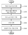
도 1은 본 발명에 따른 항공기 형상모델의 단면 절단 좌표 추출 방법의 일 실시예이다.
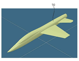
도 2는 항공기 형상모델의 일예를 도시한 도면이다.
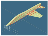
도 3은 항공기 형상모델과 평면과의 교선의 일 예를 도시한 도면이다.
도 4는 형상모델과 평면과의 교선 및 교점이 나타난 도면이다.
도 5는 오류 교선이 나타난 일 예를 도시한 도면이다.
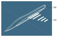
도 6은 보정이후에 획득된 데이터를 나타낸 도면이다.
도 7은 항공기 형상모델의 단면 절단 좌표 추출 방법의 다른 실시예이다.1 is an embodiment of a method for extracting cross-sectional cut coordinates of an aircraft shape model according to the present invention.
2 is a view showing an example of an aircraft shape model.
3 is a view showing an example of an intersection between an aircraft shape model and a plane.
4 is a view showing the intersection and the intersection of the shape model and the plane.
5 is a diagram illustrating an example in which an error intersection is shown.
6 is a view showing data obtained after correction.
7 is another embodiment of a method for extracting cross-sectional cut coordinates of an aircraft shape model.
이하, 본 발명의 실시 예에 항공기 형상모델의 단면 절단 좌표 추출 방법에 대하여, 첨부된 도면을 참조하여 상세히 설명한다. 그리고 이하의 실시예의 설명에서 각각의 구성요소의 명칭은 당업계에서 다른 명칭으로 호칭될 수 있다. 그러나 이들의 기능적 유사성 및 동일성이 있다면 변형된 실시예를 채용하더라도 균등한 구성으로 볼 수 있다. 또한 각각의 구성요소에 부가된 부호는 설명의 편의를 위하여 기재된다. 그러나 이들 부호가 기재된 도면상의 도시 내용이 각각의 구성요소를 도면내의 범위로 한정하지 않는다. 마찬가지로 도면상의 구성을 일부 변형한 실시예가 채용되더라도 기능적 유사성 및 동일성이 있다면 균등한 구성으로 볼 수 있다. 또한 당해 기술분야의 일반적인 기술자 수준에 비추어 보아, 당연히 포함되어야 할 구성요소로 인정되는 경우, 이에 대하여는 설명을 생략한다. Hereinafter, a method of extracting a cross-sectional cut coordinate of an aircraft shape model in an embodiment of the present invention will be described in detail with reference to the accompanying drawings. In the following description of the embodiments, the names of each component may be referred to as other names in the art. However, if they have functional similarity and identity, even if a modified embodiment is employed, it can be regarded as an even configuration. In addition, symbols added to each component are described for convenience of description. However, the illustrated contents on the drawings in which these codes are described do not limit each component to the range in the drawing. Similarly, even if an embodiment in which some modifications of the configuration on the drawing is employed, it can be regarded as an equivalent configuration if there is functional similarity and identity. In addition, in view of the level of general skill in the art, if it is recognized as a component to be included, description of it will be omitted.
한편, 이하에서의 '교선'이라 함은 평면과 형상모델간 접하는 직선 또는 곡선의 형태로 얻어지는 CONTOUR를 뜻하며, '교점' 또는 '접점'이라 함은 '교선'상의 일 좌표를 뜻함을 전제로 설명하도록 한다.On the other hand, in the following, the term 'intersection' refers to a CONTOUR obtained in the form of a straight line or a curved line between the plane and the shape model, and the term 'intersection' or 'contact point' refers to the one coordinate on the 'intersection'. Do it.
도 1은 본 발명에 따른 항공기 형상모델의 단면 절단 좌표 추출 방법의 일 실시예이고, 도 2는 항공기 형상모델의 일예를 도시한 도면이며, 도 3은 항공기 형상모델과 평면과의 교선의 일 예를 도시한 도면이다.1 is an embodiment of a method for extracting cross-sectional cut coordinates of an aircraft shape model according to the present invention, FIG. 2 is a diagram showing an example of an aircraft shape model, and FIG. 3 is an example of an intersection between an aircraft shape model and a plane It is a diagram showing.
도 4는 형상모델과 평면과의 교선 및 교점이 나타난 도면이고, 도 5는 오류 교선이 나타난 일 예를 도시한 도면이며, 도 6은 보정이후에 획득된 데이터를 나타낸 도면이다.4 is a diagram showing an intersection and a point of intersection between the shape model and the plane, FIG. 5 is a diagram showing an example in which an error intersection is shown, and FIG. 6 is a diagram showing data obtained after correction.
도시된 바와 같이, 본 발명에 따른 항공기 형상모델의 단면 절단 좌표 추출방법은 형상모델 로딩 단계(S100), 형상모델과 평면의 교선 추출 단계(S200), 오류 교선 판단 단계(S300), 보정단계(S400), 접점의 좌표 추출단계(S500)를 포함하여 구성될 수 있다.As shown, the method for extracting the cross-sectional cut coordinates of an aircraft shape model according to the present invention includes a shape model loading step (S100), an intersection extraction step of the shape model and a plane (S200), an error intersection determination step (S300), and a correction step ( S400), the coordinate extraction step of the contact point (S500).
형상모델 로딩 단계(S100)는 해석의 대상이 되는 항공기의 형상정보를 포함하는 모델을 로딩하는 단계이다. 도 2를 다시 살펴보면 형상모델 중 절반에 해당하는 모델이 로딩된 모습이 도시되어 있다. 형상모델은 항공기의 cockpit, 주익, 꼬리날개 등 항공기를 구성하는 외형적인 형상에 대하여 3차원 모델링된 데이터를 뜻하며, 항공기의 설계 단계에서는 다수의 형상모델이 생성된 뒤 이를 이용하여 해석을 수행하게 된다. 형상모델 로딩 단계(S100)에서는 항공기의 일부의 외형 또는 전체의 외형 모델을 로딩하게 된다. The shape model loading step S100 is a step of loading a model including shape information of an aircraft to be analyzed. Referring back to FIG. 2, a model corresponding to half of the shape models is loaded. The shape model refers to the three-dimensional modeled data on the external shape of the aircraft, such as the cockpit, main wing, and tail wing of the aircraft. In the design stage of the aircraft, a number of shape models are generated and then analyzed using them. . In the step of loading the shape model (S100), an external model of a part of the aircraft or an entire external model is loaded.
형상모델과 평면의 교선 추출 단계(S200)는 3차원 공간 내에서 어느 하나의 평면과 형상모델간의 교선(100)을 추출하는 단계에 해당한다. 도 3에 도시된 바와 같이, 교선 추출 단계(S200)는 복수의 평면 각각과 항공기의 형상모델과의 교선(100)을 도출하도록 구성된다. 복수의 평면은 특정 해석에 필요한 좌표에 따라 결정된다. 복수의 평면은 일 예로, 항공기의 조종안정성 해석시 피치 각(y축을 기준으로 한 회전)에 대한 해석을 수행시 x-z 평면과 평행한 다수의 평면들로 선택될 수 있다. 복수의 평면은 각각 소정거리로 이격되어 일정 간격마다 형상모델과의 교선(100)을 추출하도록 결정될 수 있다. 한편, 도 4에 나타난 바와 같이 하나의 데이터 테이블에는 3D 공간상에서 다수의 평면으로 항공기의 형상을 자른 교선(100)의 데이터, 즉 다수의 section cut 의 윤곽곡선(contour)을 포함하게 된다. The step of extracting the intersection of the shape model and the plane (S200) corresponds to the step of extracting the
한편, 교선(100)은 항공기의 외형이 급격하게 변화하는 부분에서는 해석의 정확도를 향상시킬 수 있도록 다른 영역보다 조밀하게 선정된 복수의 평면을 이용하여 교선(100)을 추출할 수 있다. 예를 들어 몸체와 주익의 연결부분과 같이 형상단면적이 급격하게 변화하는 부분에서는 윤곽곡선도 급격하게 변화가 이루어지게 되므로 몸체 중앙부에서의 복수의 평면간의 간격보다 좁게 설정되어 교선(100)을 추출하도록 구성된다.On the other hand, the
다만, x-z 평면과 평행한 복수의 평면과 형상모델간의 교선(100)을 추출하는 단계를 예를 들어 설명하였으나, 이는 일 예일 뿐, 해석에 필요한 데이터에 따라 다양한 평면을 이용하여 교선(100)을 추출할 수 있다.However, the step of extracting the
오류 교선 판단 단계(S300)는 형상모델로부터 평면과의 교선(100)이 추출된 경우 추출된 교선(100)에 오류를 포함하고 있는지 여부를 판단하는 단계이다. 오류 교선 판단 단계(S300)는 최종적으로 추출되는 방대한 좌표데이터에 오류를 최소화하여 정확도를 향상시키도록 구성된다. 오류 교선 판단 단계(S300)에서는 어느 하나의 평면과 형상모델로부터 추출된 교선(100)과 그 교선(100)에 인접하는 교선(100)과의 관계에서 오류가 있는지 판단하도록 구성된다. 인접하는 교선(100)은 항공기의 각 부분별 경계부분을 제외하고 완만한 형태의 변화를 갖게 되므로 인접하는 교선(100)의 변화 경향도 완만하게 이루어져야 한다. 따라서 각 교선(100)간의 변화 경향을 분석하여 오류가 있는지 여부를 판단할 수 있게 된다. 도 5에는 이러한 개념이 도시되어 있으며, 비정상적인 교선(100)이 추출된 경우를 인접하는 교선(100)의 변화 경향에 따라 판단하게 된다. 한편, 오류 교선 판단 단계(S300)에서 오류 교선은 변화 경향이 임계값 이상인 경우 오류 교선으로 판단할 수 있다. 교선(100)의 변화경향은 항공기의 부분별로 달라질 수 있으므로 영역을 구분하여 영역별로 다른 기준에 의해 오류를 판단할 수 있도록 구성된다. 일 예로, 주익의 경우 몸체와의 연결부분부터 끝단까지의 변화경향은 완만하게 이루어진다. 따라서 변화 경향을 판단하는 기준인 임계값이 낮게 설정된다. 한편, 몸체와 주익의 연결부분에는 급격한 변화가 이루어지므로 임계값을 높게 설정하여 정상적인 데이터가 제외되는 것을 방지할 수 있다.The error intersection determination step S300 is a step of determining whether an error is included in the extracted
보정단계(S400)는 오류 교선으로 판단된 경우 오류가 있는 부분의 데이터를 보정하는 단계에 해당한다. 오류가 있는 경우 해당 교선 전체를 제외시키지 않고 오류가 있는 좌표의 데이터를 인접하는 교선(100)의 정보로부터 추출하여 보정하게 된다. 한편 보정된 좌표 및 교선에 대하여는 차후 사용자가 확인할 수 있도록 보정여부가 기록될 수 있다. 한편, 교선(100)의 구체적인 보정방법은 다양한 방법으로 수행될 수 있으므로 이에 대한 상세한 설명은 생략하도록 한다.The correction step (S400) corresponds to a step of correcting data of an error portion when it is determined that the error is an intersection. If there is an error, the data of the coordinates having an error is extracted from the information of the
접점의 좌표 추출단계(S500)는 복수의 교선(100)으로부터 일정간격으로 좌표를 추출하는 단계에 해당한다. 추출된 좌표는 다른 해석, 예를 들어 조종 안정성 해석에 적용하기 용이한 데이터 테이블과 같은 형태로 출력될 수 있다. 도 6에는 추출된 데이터와 데이터 테이블이 도시되어 있다. 다만, 접점(200)의 좌표를 추출한 이후 테이블로 추출한 예를 들어 설명하였으나, 이는 일 예일 뿐, 좌표 인식이 가능한 다양한 형태로 출력될 수 있다. The step of extracting the coordinates of the contact (S500) corresponds to the step of extracting the coordinates at regular intervals from the plurality of
이하에서는 도 7을 참조하여 본 발명에 따른 항공기 형상모델의 단면 절단 좌표 추출 방법의 다른 실시예에 대하여 도 7을 참조하여 설명하도록 한다. 본 실시예에서도 전술한 실시예와 동일한 구성요소를 포함하여 구성될 수 있으며, 이에 대하여는 중복기재를 피하기 위해 설명을 생략하고 차이가 있는 구성에 대하여 상세히 설명하도록 한다.Hereinafter, another embodiment of a method for extracting cross-sectional cut coordinates of an aircraft shape model according to the present invention will be described with reference to FIG. 7 with reference to FIG. 7. In this embodiment, it may also be configured to include the same components as the above-described embodiment, and for this, the description will be omitted in order to avoid overlapping description, and a detailed description of the difference configuration.
도 7은 항공기 형상모델의 단면 절단 좌표 추출 방법의 다른 실시예이다.7 is another embodiment of a method for extracting cross-sectional cut coordinates of an aircraft shape model.
도시된 바와 같이, 본 발명에 따른 제2 실시예는 형상모델과 평면의 교선 추출단계(S200) 이후 접점의 좌표 추출단계(S500), 오류 좌표 판단단계(S350), 보정단계(S400) 및 전체 교선 추출 여부 판단 단계(S600)를 포함하여 구성될 수 있다.As shown in the figure, the second embodiment according to the present invention extracts the coordinates of the contact point (S500), the error coordinate determination step (S350), the correction step (S400) and the whole after the intersection extraction step (S200) of the shape model and the plane. It may be configured to include a step of determining whether or not to extract the intersection (S600).
접점의 좌표 추출단계(S500)는 전술한 제1 실시예에서와 동일하게 교선(100)으로부터 접점의 좌표를 추출하는 단계에 해당한다. The step of extracting the coordinates of the contact (S500) corresponds to the step of extracting the coordinates of the contact from the
오류 좌표 판단단계(S350)는 추출된 복수의 좌표 중 오류가 있는지 여부를 판단하는 단계에 해당한다. 오류 좌표 판단 단계(S350)는 하나의 교선(100) 상에서 추출될 수 있는 복수의 교점(200) 좌표들간의 변화 경향을 판단하여 오류가 있는지 여부를 판단하는 단계에 해당한다. 오류 좌표의 판단은 인접하는 좌표들 간의 변화 경향이 임계값 이상이 되는 경우 오류 좌표로 판단할 수 있으며, 임계값은 항공기의 부분별로 다르게 적용될 수 있다. 예를 들어 주익은 상면과 하면의 변화 경향은 완만하며, 전방면과 후방에 위치한 조종면의 형상에 대한 교점의 변화는 급격하게 이루어지므로 부분별로 구분하여 임계값을 다르게 구성하여 오류를 판단할 수 있다. The error coordinate determination step S350 corresponds to a step of determining whether there is an error among the plurality of extracted coordinates. The error coordinate determination step S350 corresponds to a step of determining whether there is an error by determining a tendency to change between coordinates of a plurality of intersection points 200 that can be extracted on one
보정단계(S400)는 오류 좌표에 대하여 보정을 수행하는 단계에 해당한다. 추출된 좌표가 오류 좌표로 판단된 경우 인접하는 좌표의 변화경향을 반영하여 보정할 수 있도록 구성된다. 좌표의 보정은 인접하는 복수의 좌표값을 이용하여 수행될 수 있다.The correction step S400 corresponds to a step of performing correction on the error coordinates. When the extracted coordinates are determined to be error coordinates, it is configured to be corrected by reflecting the tendency of change of adjacent coordinates. Correction of coordinates may be performed using a plurality of adjacent coordinate values.
전체 교선 추출 여부 판단 단계(S600)는 단면 좌표 추출을 위해 설정한 복수의 평면 전체에 대하여 교선이 추출되었는지 여부를 판단하는 단계이다. 전체 교선이 추출되지 않은 경우는 교선 추출 단계 내지 보정 단계가 반복적으로 수행되도록 구성될 수 있다.The determination of whether to extract the entire intersection (S600) is a step of determining whether the intersection is extracted with respect to the entire plurality of planes set for extracting the cross-section coordinates. When the entire intersection is not extracted, it may be configured such that the intersection extraction step or the correction step are repeatedly performed.
이상에서 설명한 바와 같이, 본 발명에 따른 항공기 형상모델의 단면 절단 좌표 추출 방법은 항공기에 특화되어 각 형상별로 영역을 구분하고 오류를 판단하여 외면의 좌표를 추출할 수 있으므로 정확도 및 데이터 추출의 효율 향상의 효과가 있다.As described above, the method for extracting the cross-sectional cut coordinates of the aircraft shape model according to the present invention is specialized for aircrafts, so it is possible to classify the area for each shape and determine the error to extract the coordinates of the outer surface, thus improving accuracy and efficiency of data extraction. Has the effect of
10: 형상모델
100: 교선
200: 교점
S100: 형상모델 로딩 단계
S200: 형상모델과 평면의 교선 추출 단계
S300: 오류 교선 판단 단계
S350: 오류 좌표 판단 단계
S400: 보정 단계
S500: 접점의 좌표 추출 단계
S600: 전체 교선 추출 여부 판단 단계10: shape model
100: crossing
200: intersection
S100: Step of loading the shape model
S200: Extraction of the intersection of the shape model and the plane
S300: error intersection judgment step
S350: error coordinate determination step
S400: calibration step
S500: Coordinate extraction step of contact
S600: Step for determining whether to extract the entire bridge
Claims (6)
상기 형상모델과 소정방향의 평면간 교선을 추출하는 단계;
상기 교선 중 오류 교선을 판단하는 단계;
상기 복수의 교선에 오류가 발생한 경우 보정하는 단계; 및
상기 교선으로부터 복수의 접점의 좌표를 추출하는 단계를 포함하는 항공기 형상모델의 단면 절단 좌표 추출 방법.Loading a shape model of at least a portion of the aircraft;
Extracting an intersection between the shape model and a plane in a predetermined direction;
Determining an error intersection among the intersections;
Correcting an error in the plurality of intersections; And
And extracting coordinates of a plurality of contact points from the intersection line.
상기 소정방향의 평면은 서로 평행한 복수의 평면을 포함하여 구성되며,
상기 교선을 추출하는 단계는 복수의 평면 중 각각의 평면마다 추출되는 것을 특징으로 하는 항공기 형상모델의 단면 절단 좌표 추출 방법.According to claim 1,
The plane in the predetermined direction includes a plurality of planes parallel to each other,
The extraction of the intersection line is a method of extracting cross-sectional cut coordinates of an aircraft shape model, characterized in that it is extracted for each plane among a plurality of planes.
상기 오류 교선을 판단하는 단계는,
상기 복수의 평면과의 교선 간 변화 경향을 파악하며, 인접하는 교선의 소정범위내 변화가 임계값 이상인 경우 오류 교선으로 판단하는 것을 특징으로 하는 항공기 형상모델의 단면 절단 좌표 추출 방법.According to claim 2,
The step of determining the error intersection,
A method of extracting cross-sectional cut coordinates of an aircraft shape model, characterized in that a tendency to change between intersections with the plurality of planes is determined and an error intersection is determined when a change in a predetermined range of adjacent intersections is greater than or equal to a threshold.
상기 임계값은,
상기 항공기의 형상을 복수의 영역으로 구분하며, 상기 복수의 영역에 따라 다르게 적용되는 것을 특징으로 하는 항공기 형상모델의 단면 절단 좌표 추출 방법.According to claim 3,
The threshold is,
A method for extracting cross-sectional cut coordinates of an aircraft shape model, wherein the shape of the aircraft is divided into a plurality of regions and differently applied according to the plurality of regions.
상기 복수의 영역은,
상기 항공기의 cockpit을 포함한 전방 영역 및 상기 항공기의 주익의 조종면을 포함하는 후방 영역을 포함하여 구성되는 것을 특징으로 하는 항공기 형상모델의 단면 절단 좌표 추출 방법.According to claim 4,
The plurality of regions,
Method for extracting cross-sectional cut coordinates of an aircraft shape model, characterized in that it comprises a front area including the cockpit of the aircraft and a rear area including the control surface of the main wing of the aircraft.
상기 보정하는 단계는,
상기 오류 교선에 인접하는 교선에서 인접하는 복수의 교점의 좌표값을 근거로 보정하는 것을 특징으로 하는 항공기 형상모델의 단면 절단 좌표 추출 방법.
According to claim 2,
The correction step,
A method of extracting cross-sectional cut coordinates of an aircraft shape model, characterized in that correction is made based on coordinate values of a plurality of intersection points adjacent to the error intersection line.
Priority Applications (1)
| Application Number | Priority Date | Filing Date | Title |
|---|---|---|---|
| KR1020180113136A KR102215235B1 (en) | 2018-09-20 | 2018-09-20 | Method of calculating cross-sectional cutting coordinates of aircraft shape model |
Applications Claiming Priority (1)
| Application Number | Priority Date | Filing Date | Title |
|---|---|---|---|
| KR1020180113136A KR102215235B1 (en) | 2018-09-20 | 2018-09-20 | Method of calculating cross-sectional cutting coordinates of aircraft shape model |
Publications (2)
| Publication Number | Publication Date |
|---|---|
| KR20200033620A true KR20200033620A (en) | 2020-03-30 |
| KR102215235B1 KR102215235B1 (en) | 2021-02-15 |
Family
ID=70003507
Family Applications (1)
| Application Number | Title | Priority Date | Filing Date |
|---|---|---|---|
| KR1020180113136A KR102215235B1 (en) | 2018-09-20 | 2018-09-20 | Method of calculating cross-sectional cutting coordinates of aircraft shape model |
Country Status (1)
| Country | Link |
|---|---|
| KR (1) | KR102215235B1 (en) |
Citations (9)
| Publication number | Priority date | Publication date | Assignee | Title |
|---|---|---|---|---|
| JPH061161B2 (en) * | 1985-11-13 | 1994-01-05 | アニマ株式会社 | Cross-sectional shape measurement display device |
| WO2011062682A2 (en) * | 2009-11-23 | 2011-05-26 | The Boeing Company | Weight-optimizing internally pressurized composite-body aircraft fuselages having near-elliptical cross sections |
| JP2011197925A (en) * | 2010-03-18 | 2011-10-06 | Honda Motor Co Ltd | System and program for supporting design |
| JP5416410B2 (en) * | 2005-11-15 | 2014-02-12 | ザ・ボーイング・カンパニー | Weight-optimized pressurizable aircraft fuselage structure with a near-elliptical cross section |
| JP2014132437A (en) * | 2013-01-02 | 2014-07-17 | Boeing Co | Systems and methods for stand-off inspection of aircraft structures |
| KR101454780B1 (en) * | 2013-06-10 | 2014-10-27 | 한국과학기술연구원 | Apparatus and method for generating texture for three dimensional model |
| KR101552828B1 (en) | 2015-05-27 | 2015-09-14 | (주)이지스 | Method for Obtaining Polygon Information of Three-dimensional Object Model |
| JP2016136111A (en) * | 2015-01-23 | 2016-07-28 | シャープ株式会社 | Shape error determination device and determination result image generation device |
| JP2018030569A (en) * | 2016-06-24 | 2018-03-01 | ザ・ボーイング・カンパニーThe Boeing Company | Modeling and analysis of leading-edge rib of aircraft wing |
-
2018
- 2018-09-20 KR KR1020180113136A patent/KR102215235B1/en active IP Right Grant
Patent Citations (9)
| Publication number | Priority date | Publication date | Assignee | Title |
|---|---|---|---|---|
| JPH061161B2 (en) * | 1985-11-13 | 1994-01-05 | アニマ株式会社 | Cross-sectional shape measurement display device |
| JP5416410B2 (en) * | 2005-11-15 | 2014-02-12 | ザ・ボーイング・カンパニー | Weight-optimized pressurizable aircraft fuselage structure with a near-elliptical cross section |
| WO2011062682A2 (en) * | 2009-11-23 | 2011-05-26 | The Boeing Company | Weight-optimizing internally pressurized composite-body aircraft fuselages having near-elliptical cross sections |
| JP2011197925A (en) * | 2010-03-18 | 2011-10-06 | Honda Motor Co Ltd | System and program for supporting design |
| JP2014132437A (en) * | 2013-01-02 | 2014-07-17 | Boeing Co | Systems and methods for stand-off inspection of aircraft structures |
| KR101454780B1 (en) * | 2013-06-10 | 2014-10-27 | 한국과학기술연구원 | Apparatus and method for generating texture for three dimensional model |
| JP2016136111A (en) * | 2015-01-23 | 2016-07-28 | シャープ株式会社 | Shape error determination device and determination result image generation device |
| KR101552828B1 (en) | 2015-05-27 | 2015-09-14 | (주)이지스 | Method for Obtaining Polygon Information of Three-dimensional Object Model |
| JP2018030569A (en) * | 2016-06-24 | 2018-03-01 | ザ・ボーイング・カンパニーThe Boeing Company | Modeling and analysis of leading-edge rib of aircraft wing |
Also Published As
| Publication number | Publication date |
|---|---|
| KR102215235B1 (en) | 2021-02-15 |
Similar Documents
| Publication | Publication Date | Title |
|---|---|---|
| KR100914218B1 (en) | System and method for calculating loft surfaces using ?d scan data | |
| US11163916B2 (en) | Automatic generation of dimension and tolerance information for fastened components | |
| CN110688709B (en) | Workpiece point cloud model-based skin process model correction method | |
| CN105740522B (en) | A kind of Datum reference frames auto-creating method of orientated tolerance technology | |
| EP2498192A2 (en) | Method for creating finite element model of rubber composite | |
| CN113741426B (en) | Robot machining path planning method based on local point cloud curve fitting | |
| CN113888668A (en) | Parallelized vehicle collision analysis | |
| US11222480B2 (en) | Designing assistance system, designing assistance method, and computer readable medium | |
| KR102215235B1 (en) | Method of calculating cross-sectional cutting coordinates of aircraft shape model | |
| US10824133B2 (en) | Method for generating numerical control program, element creation method, generation system, and generation program | |
| US11294352B2 (en) | Cross-section identification system | |
| CN107567641B (en) | System and method for identifying replicas | |
| US20190026399A1 (en) | Analysis model creation assistance device and analysis model creation assistance method | |
| US7236168B2 (en) | Method for removing blends in B-rep models | |
| JP5383230B2 (en) | NC data correction method and apparatus | |
| US20180196912A1 (en) | Method and Device for Generating a Sectional View of a Body of a Vehicle | |
| JP4374068B1 (en) | Method for approximating line segment of edge point sequence | |
| Bilodeau et al. | Part segmentation of objects in real images | |
| US10843275B2 (en) | Numerical control systems and methods for determining raw material shape and determining a gripping part | |
| US11998405B2 (en) | Method for planning a dental structure | |
| US20240054810A1 (en) | Learning method for a machine learning system for detecting and modeling an object in an image, corresponding computer program product and device | |
| US20030187541A1 (en) | Design supporting program, design supporting method, design supporting apparatus and computer-readable recording medium recorded with design supporting program | |
| JP2007233585A (en) | Design support method and its system | |
| KR20210098103A (en) | System and method for parts manufacturability verification based on machining feature recognition | |
| US20060277003A1 (en) | Computer aided design associative design process |
Legal Events
| Date | Code | Title | Description |
|---|---|---|---|
| E90F | Notification of reason for final refusal | ||
| E701 | Decision to grant or registration of patent right | ||
| GRNT | Written decision to grant |