KR20200030464A - Improved aneurysm occlusion device - Google Patents
Improved aneurysm occlusion device Download PDFInfo
- Publication number
- KR20200030464A KR20200030464A KR1020190111957A KR20190111957A KR20200030464A KR 20200030464 A KR20200030464 A KR 20200030464A KR 1020190111957 A KR1020190111957 A KR 1020190111957A KR 20190111957 A KR20190111957 A KR 20190111957A KR 20200030464 A KR20200030464 A KR 20200030464A
- Authority
- KR
- South Korea
- Prior art keywords
- occlusion device
- aneurysm
- end region
- proximal end
- tubular structure
- Prior art date
Links
Images


Classifications
-
- A—HUMAN NECESSITIES
- A61—MEDICAL OR VETERINARY SCIENCE; HYGIENE
- A61B—DIAGNOSIS; SURGERY; IDENTIFICATION
- A61B17/00—Surgical instruments, devices or methods, e.g. tourniquets
- A61B17/12—Surgical instruments, devices or methods, e.g. tourniquets for ligaturing or otherwise compressing tubular parts of the body, e.g. blood vessels, umbilical cord
- A61B17/12022—Occluding by internal devices, e.g. balloons or releasable wires
- A61B17/12027—Type of occlusion
- A61B17/12031—Type of occlusion complete occlusion
-
- A—HUMAN NECESSITIES
- A61—MEDICAL OR VETERINARY SCIENCE; HYGIENE
- A61B—DIAGNOSIS; SURGERY; IDENTIFICATION
- A61B17/00—Surgical instruments, devices or methods, e.g. tourniquets
- A61B17/12—Surgical instruments, devices or methods, e.g. tourniquets for ligaturing or otherwise compressing tubular parts of the body, e.g. blood vessels, umbilical cord
- A61B17/12022—Occluding by internal devices, e.g. balloons or releasable wires
- A61B17/12099—Occluding by internal devices, e.g. balloons or releasable wires characterised by the location of the occluder
- A61B17/12109—Occluding by internal devices, e.g. balloons or releasable wires characterised by the location of the occluder in a blood vessel
- A61B17/12113—Occluding by internal devices, e.g. balloons or releasable wires characterised by the location of the occluder in a blood vessel within an aneurysm
-
- A—HUMAN NECESSITIES
- A61—MEDICAL OR VETERINARY SCIENCE; HYGIENE
- A61B—DIAGNOSIS; SURGERY; IDENTIFICATION
- A61B17/00—Surgical instruments, devices or methods, e.g. tourniquets
- A61B17/12—Surgical instruments, devices or methods, e.g. tourniquets for ligaturing or otherwise compressing tubular parts of the body, e.g. blood vessels, umbilical cord
- A61B17/12022—Occluding by internal devices, e.g. balloons or releasable wires
- A61B17/12131—Occluding by internal devices, e.g. balloons or releasable wires characterised by the type of occluding device
- A61B17/1214—Coils or wires
-
- A—HUMAN NECESSITIES
- A61—MEDICAL OR VETERINARY SCIENCE; HYGIENE
- A61B—DIAGNOSIS; SURGERY; IDENTIFICATION
- A61B17/00—Surgical instruments, devices or methods, e.g. tourniquets
- A61B17/12—Surgical instruments, devices or methods, e.g. tourniquets for ligaturing or otherwise compressing tubular parts of the body, e.g. blood vessels, umbilical cord
- A61B17/12022—Occluding by internal devices, e.g. balloons or releasable wires
- A61B17/12131—Occluding by internal devices, e.g. balloons or releasable wires characterised by the type of occluding device
- A61B17/12168—Occluding by internal devices, e.g. balloons or releasable wires characterised by the type of occluding device having a mesh structure
- A61B17/12172—Occluding by internal devices, e.g. balloons or releasable wires characterised by the type of occluding device having a mesh structure having a pre-set deployed three-dimensional shape
-
- A—HUMAN NECESSITIES
- A61—MEDICAL OR VETERINARY SCIENCE; HYGIENE
- A61L—METHODS OR APPARATUS FOR STERILISING MATERIALS OR OBJECTS IN GENERAL; DISINFECTION, STERILISATION OR DEODORISATION OF AIR; CHEMICAL ASPECTS OF BANDAGES, DRESSINGS, ABSORBENT PADS OR SURGICAL ARTICLES; MATERIALS FOR BANDAGES, DRESSINGS, ABSORBENT PADS OR SURGICAL ARTICLES
- A61L31/00—Materials for other surgical articles, e.g. stents, stent-grafts, shunts, surgical drapes, guide wires, materials for adhesion prevention, occluding devices, surgical gloves, tissue fixation devices
- A61L31/02—Inorganic materials
- A61L31/022—Metals or alloys
-
- A—HUMAN NECESSITIES
- A61—MEDICAL OR VETERINARY SCIENCE; HYGIENE
- A61L—METHODS OR APPARATUS FOR STERILISING MATERIALS OR OBJECTS IN GENERAL; DISINFECTION, STERILISATION OR DEODORISATION OF AIR; CHEMICAL ASPECTS OF BANDAGES, DRESSINGS, ABSORBENT PADS OR SURGICAL ARTICLES; MATERIALS FOR BANDAGES, DRESSINGS, ABSORBENT PADS OR SURGICAL ARTICLES
- A61L31/00—Materials for other surgical articles, e.g. stents, stent-grafts, shunts, surgical drapes, guide wires, materials for adhesion prevention, occluding devices, surgical gloves, tissue fixation devices
- A61L31/14—Materials characterised by their function or physical properties, e.g. injectable or lubricating compositions, shape-memory materials, surface modified materials
- A61L31/18—Materials at least partially X-ray or laser opaque
-
- A—HUMAN NECESSITIES
- A61—MEDICAL OR VETERINARY SCIENCE; HYGIENE
- A61M—DEVICES FOR INTRODUCING MEDIA INTO, OR ONTO, THE BODY; DEVICES FOR TRANSDUCING BODY MEDIA OR FOR TAKING MEDIA FROM THE BODY; DEVICES FOR PRODUCING OR ENDING SLEEP OR STUPOR
- A61M25/00—Catheters; Hollow probes
- A61M25/0021—Catheters; Hollow probes characterised by the form of the tubing
-
- A—HUMAN NECESSITIES
- A61—MEDICAL OR VETERINARY SCIENCE; HYGIENE
- A61B—DIAGNOSIS; SURGERY; IDENTIFICATION
- A61B17/00—Surgical instruments, devices or methods, e.g. tourniquets
- A61B2017/00831—Material properties
- A61B2017/00902—Material properties transparent or translucent
- A61B2017/00915—Material properties transparent or translucent for radioactive radiation
-
- A—HUMAN NECESSITIES
- A61—MEDICAL OR VETERINARY SCIENCE; HYGIENE
- A61B—DIAGNOSIS; SURGERY; IDENTIFICATION
- A61B17/00—Surgical instruments, devices or methods, e.g. tourniquets
- A61B17/12—Surgical instruments, devices or methods, e.g. tourniquets for ligaturing or otherwise compressing tubular parts of the body, e.g. blood vessels, umbilical cord
- A61B17/12022—Occluding by internal devices, e.g. balloons or releasable wires
- A61B2017/1205—Introduction devices
- A61B2017/12054—Details concerning the detachment of the occluding device from the introduction device
-
- A—HUMAN NECESSITIES
- A61—MEDICAL OR VETERINARY SCIENCE; HYGIENE
- A61M—DEVICES FOR INTRODUCING MEDIA INTO, OR ONTO, THE BODY; DEVICES FOR TRANSDUCING BODY MEDIA OR FOR TAKING MEDIA FROM THE BODY; DEVICES FOR PRODUCING OR ENDING SLEEP OR STUPOR
- A61M25/00—Catheters; Hollow probes
- A61M25/0021—Catheters; Hollow probes characterised by the form of the tubing
- A61M2025/0042—Microcatheters, cannula or the like having outside diameters around 1 mm or less
Abstract
Description
관련 출원의 상호 참조Cross reference of related applications
본 출원은, 그 내용이 전체적으로 본 명세서에 참고로 포함되는, 2014년 3월 31일자로 출원된 미국 특허 출원 제14/230,426호의 일부 계속 출원이다.This application is a continuation of a portion of U.S. Patent Application No. 14 / 230,426 filed March 31, 2014, the contents of which are incorporated herein by reference in their entirety.
기술분야Technology field
본 발명은 신체 혈관 내의 임플란트(implant)에 관한 것으로, 보다 상세하게는 동맥류(aneurysm)의 경부(neck)와 같은 작은 혈관 개구를 위한 폐색 장치(occlusion device)에 관한 것이다.The present invention relates to an implant in a body blood vessel, and more particularly, to an occlusion device for opening a small blood vessel, such as a neck of an aneurysm.
동맥류 및 다른 동정맥 기형(arterio-venous malformation)과 같은 혈관 장애 및 결손은 중요 조직 부근에 위치될 때 또는 기형부에의 용이한 접근이 불가한 경우에 특히 치료하기 어렵다. 이러한 두 어려움의 요인은 특히 뇌동맥류(cranial aneurysm)에 적용된다. 두개 혈관을 둘러싸는 민감한 뇌 조직과 제한된 접근으로 인해, 두개 혈관구조의 결손을 수술적으로 치료하는 것은 매우 어렵고 흔히 위험하다.Vascular disorders and defects such as aneurysms and other arterio-venous malformation are particularly difficult to treat when located near critical tissue or where easy access to malformations is not possible. These two difficulties are particularly applicable to cranial aneurysm. Due to the sensitive brain tissue surrounding the cranial vessels and limited access, surgical treatment of deficits in the cranial vasculature is very difficult and often dangerous.
혈관내 임플란트(endovascular implant)에 의한 동맥류의 치료에서, 목표는 동맥 혈압 및 혈류(blood pressure and flow)로부터 동맥류 낭(aneurysm sac)의 내부 체적을 배제시키는 것이다. 동맥류의 내벽이 혈압 및/또는 혈류를 받는 한, 동맥류 파열의 위험이 있다.In the treatment of an aneurysm by an endovascular implant, the goal is to exclude the internal volume of the aneurysm sac from arterial blood pressure and flow. As long as the inner wall of the aneurysm receives blood pressure and / or blood flow, there is a risk of aneurysm rupture.
비-수술적 치료는 카테터 전달 시스템(catheter delivery system)을 사용하여 전개되는 색전 코일(embolic coil)과 같은 혈관 폐색 장치를 포함한다. 뇌동맥류를 치료하기 위한 현재 바람직한 시술에서, 색전 코일 전달 카테터의 원위 단부가 초기에 전형적으로 서혜부 내의 대퇴 동맥을 통해 환자의 비-두개 혈관구조 내로 삽입되고, 두개 내의 혈관 내의 사전결정된 전달 부위로 안내된다. 이어서, 동맥류 낭이 혈압 및 혈류로부터 벽을 보호하는 고형 혈전 덩어리(solid thrombotic mass)의 형성을 유발하는 색전 재료로 충전된다. 바람직하게는, 혈전 덩어리는 동맥류의 경부의 평면을 따라 원래 혈관 형상을 실질적으로 복원시킨다. 경부 평면은 동맥류의 형성이 없었다면 혈관의 내막(intima)이 있을 가상 표면이다. 그러나, 단순히 색전 코일을 이용하는 것은 동맥류의 재-소통(re-canalization) 및/또는 코일 압밀(coil compaction)이 시간 경과에 따라 발생할 수 있기 때문에 동맥류를 치료하는 데 항상 효과적이지는 않다.Non-surgical treatments include vascular occlusion devices such as embolic coils that are deployed using a catheter delivery system. In currently preferred procedures for treating cerebral aneurysms, the distal end of the embolic coil delivery catheter is initially inserted into the patient's non-cranial vascular structure, typically through the femoral artery in the inguinal region, and guided to a predetermined delivery site within the blood vessels in the skull. do. The aneurysm sac is then filled with embolic material causing the formation of a solid thrombotic mass that protects the walls from blood pressure and blood flow. Preferably, the thrombus mass substantially restores the original blood vessel shape along the plane of the neck of the aneurysm. The cervical plane is an imaginary surface that will have an intima of blood vessels without aneurysm formation. However, simply using an embolic coil is not always effective in treating an aneurysm because re-canalization of the aneurysm and / or coil compaction may occur over time.
동맥류 낭에 사용하기 위한 백(bag)이 그린핼프(Greenhalgh)에 의해 미국 특허 제6,346,117호 및 제6,391,037호에 기술되고, 동맥류 경부 차단 장치가 월리스(Wallace)에 의한 미국 특허 제6,454,780호에 도시된다. 탈착가능 경부 브리지(detachable neck bridge)가 예를 들어 에이브럼스(Abrams) 등에 의해 미국 특허 제6,036,720호에 그리고 머피(Murphy) 등에 의해 미국 특허 제7,410,482호에 개시된다. 바람직하게는, 하나 이상의 색전 코일이 경부 브리지 또는 다른 차단 장치 내로 또는 그것을 통해 전달되어 동맥류의 낭을 충전한다.A bag for use in an aneurysm sac is described in US Pat. Nos. 6,346,117 and 6,391,037 by Greenhalgh, and an aneurysm neck blocker is shown in US Pat. No. 6,454,780 by Wallace. . Detachable neck bridges are disclosed, for example, in U.S. Pat.No. 6,036,720 by Abrams et al., And in U.S. Pat.No. 7,410,482 by Murphy et al. Preferably, one or more embolic coils are delivered into or through a cervical bridge or other blocking device to fill the sac of an aneurysm.
또 다른 유형의 혈관-폐색 장치가 동맥류 또는 누공(fistula)과 같은 혈관 공동 내에 배치된 후에 이완될 때 대체로 구형(spherical) 또는 난형(ovoid) 혈관-폐색 구조체를 형성하도록 권취되는 가요성 재료의 하나 이상의 스트랜드(strand)를 구비하는 것으로 호튼(Horton)에 의한 미국 특허 제5,645,558호에 예시된다. 유사하게, 굴리엘미(Guglielmi)에 의한 미국 특허 제5,916,235호는 탈착가능 코일을 기술한 이전의 특허를 인용한 다음에, 케이지(cage)가 동맥류 내에서 확장된 후에 하나 이상의 코일을 수용하고 유지시킬 수 있는 혈관-폐색 구조체로서 그러한 확장가능 케이지를 개시한다. 자가-확장가능 동맥류 충전 장치가 베즈네다로글루(Veznedaroglu) 등에 의한 미국 특허 공개 제2010/0069948호에 개시된다.One type of flexible material that is wound to form a generally spherical or ovoid vascular-occlusive structure when another type of vascular-occlusive device is relaxed after being placed in a vascular cavity such as an aneurysm or fistula It is exemplified in U.S. Patent No. 5,645,558 by Horton as having the above strand. Similarly, U.S. Patent No. 5,916,235 by Guglielmi cited a previous patent describing a removable coil, and then received and retained one or more coils after the cage was expanded in an aneurysm. Such expandable cages are disclosed as possible vascular-occlusive structures. A self-expandable aneurysm filling device is disclosed in U.S. Patent Publication No. 2010/0069948 by Veznedaroglu et al.
따라서, 혈관에서 동맥류의 경부 또는 다른 동정맥 기형을 효과적으로 폐색시키기 위해 하나 이상의 색전 코일 또는 다른 혈관-폐색 구조체와 협동하는 회수가능한, 재위치가능한 장치를 구비하는 것이 바람직하다.Thus, it is desirable to have a recoverable, repositionable device that cooperates with one or more embolic coils or other vascular-occlusive structures to effectively occlude cervical or other arteriovenous malformations of the aneurysm in the blood vessel.
본 발명의 목적은 혈관 내의 동맥류 내로의 혈류를 실질적으로 차단하는 개선된 폐색 장치를 제공하는 것이다.It is an object of the present invention to provide an improved occlusion device that substantially blocks blood flow into an aneurysm in a blood vessel.
본 발명의 다른 목적은 동맥류의 낭으로부터 재위치되거나 회수될 수 있는 그러한 폐색 장치를 제공하는 것이다.Another object of the present invention is to provide such an occlusion device that can be repositioned or recovered from the sac of an aneurysm.
본 발명은 제1 확장 상태(expanded condition) 및 제2 수축 상태(collapsed condition)를 갖는, 근위 단부 영역 및 원위 단부 영역을 갖는 실질적으로 튜브형 구조체(tubular structure)를 포함하는, 환자 내의 혈관 내의 동맥류의 혈관내 치료에 적합한 폐색 장치를 특징으로 한다. 장치는 환자의 혈관구조를 통한 그리고 동맥류의 경부를 통한 삽입에 적합한 제2 수축 상태에서의 치수를 갖는다. 장치는, 구조체의 근위 단부 영역 상에 배치되는 실질적으로 환형 본체(annular body)를 갖고 근위 단부 영역의 반경방향 확장을 방지하기 위해 그리고 폐색 장치의 조작 중에 맞물림 특징부를 제공하기 위해 근위 단부 영역을 적어도 실질적으로 둘러싸는 제어 링(control ring)을 추가로 포함한다.The present invention relates to an aneurysm in a blood vessel in a patient, comprising a substantially tubular structure having a proximal end region and a distal end region, having a first expanded condition and a second collapsed condition. It is characterized by an occlusion device suitable for intravascular treatment. The device is dimensioned in a second contraction state suitable for insertion through the patient's vasculature and through the neck of the aneurysm. The device has a substantially annular body disposed on the proximal end area of the structure and at least the proximal end area to prevent radial expansion of the proximal end area and to provide engagement features during operation of the occlusion device. It further comprises a control ring substantially enclosing.
다수의 실시예에서, 제어 링은 내측 슬리브(inner sleeve)에 의해 확립되는 채널(channel)과 같은 내측 통로를 한정하고, 내측 통로를 통해 적어도 하나의 색전 코일이 동맥류 내로 삽입가능하다. 바람직하게는, 튜브형 구조체의 근위 단부 영역의 적어도 일부분은 동맥류의 폐색을 향상시키기에 충분히 작은 크기를 갖는 복수의 개구들을 한정한다. 몇몇 실시예에서, 튜브형 구조체는 수축가능 케이지-유사 장치와 같은 적어도 하나의 혈관-폐색 구조체와 협동한다.In many embodiments, the control ring defines an inner passage, such as a channel established by an inner sleeve, through which the at least one embolic coil is insertable into the aneurysm. Preferably, at least a portion of the proximal end region of the tubular structure defines a plurality of openings that are small enough to enhance occlusion of the aneurysm. In some embodiments, the tubular structure cooperates with at least one vascular-occlusive structure, such as a retractable cage-like device.
소정 실시예에서, 폐색 장치는, 내측 루멘(inner lumen)을 한정하고 적어도 2개의 핑거 요소(finger element)들을 구비한 그래버(grabber)를 보유하는 원위 단부 영역을 갖는 전달 부재와 조합되어 이용될 수 있고, 각각의 핑거 요소는 제어 링과 기계적으로 맞물리는 파지 영역을 한정한다. 일 실시예에서, 그래버는 금속 재료로 형성되고, 파지 영역들은 핑거 요소들 내에 형성되는 노치(notch)들이고, 각각의 노치는 제어 링의 일부분과 기계적으로 맞물리도록 크기설정된다. 이러한 조합은 내측 루멘을 갖는 카테터를 추가로 포함할 수 있고, 내측 루멘을 통해 전달 튜브가 삽입가능하고 카테터에 대해 병진가능하다.In certain embodiments, the occlusion device may be used in combination with a delivery member having a distal end region that holds a grabber with at least two finger elements defining an inner lumen. Each finger element defines a gripping area that mechanically engages the control ring. In one embodiment, the grabber is formed of a metallic material, the gripping regions are notches formed in the finger elements, and each notch is sized to mechanically engage a portion of the control ring. This combination may further include a catheter with an inner lumen, through which the delivery tube is insertable and translatable to the catheter.
본 발명은 또한 환자 내의 혈관 내의 동맥류를 치료하는 방법으로서 표현될 수 있고, 방법은 제1 확장 상태 및 제2 수축 상태를 갖는, 근위 단부 영역 및 원위 단부 영역을 갖는 실질적으로 튜브형 구조체를 갖는 구조체를 구비한, 그리고 환자의 혈관구조를 통한 그리고 동맥류의 경부를 통한 삽입에 적합한 제2 수축 상태에서의 치수를 갖는 폐색 장치를 선택하는 단계를 포함한다. 장치는, 구조체의 근위 단부 영역 상에 배치되는 실질적으로 환형 본체를 갖고 근위 단부 영역의 반경방향 확장을 방지하기 위해 근위 단부 영역을 적어도 실질적으로 둘러싸는 제어 링을 추가로 포함한다.The invention can also be expressed as a method of treating an aneurysm in a blood vessel in a patient, the method comprising a structure having a substantially tubular structure having a proximal end region and a distal end region, having a first expanded state and a second contracted state. And selecting an occlusion device having a dimension in a second contraction state that is suitable for insertion through the patient's vascular structure and through the neck of the aneurysm. The device further includes a control ring having a substantially annular body disposed on the proximal end region of the structure and at least substantially surrounding the proximal end region to prevent radial expansion of the proximal end region.
몇몇 실시예에서, 방법은 폐색 장치의 조작을 가능하게 하도록 제어 링을 전달 튜브 상의 그래버와 기계적으로 맞물리게 하는 단계, 폐색 장치를 수축 상태에 있게 하도록 폐색 장치를 전달 튜브를 보유하는 카테터 내로 끌어당기는 단계, 폐색 장치를 가진 카테터를 혈관 내의 동맥류의 영역에 도달하도록 환자의 혈관구조 내로 삽입하는 단계, 및 폐색 장치를 동맥류 내에 위치시키는 단계를 추가로 포함한다.In some embodiments, the method includes mechanically engaging the control ring with a grabber on the delivery tube to enable manipulation of the obstruction device, and pulling the obstruction device into the catheter holding the delivery tube to bring the obstruction device into a retracted state. , Inserting the catheter with the occlusion device into the patient's vasculature to reach an area of the aneurysm in the blood vessel, and placing the occlusion device within the aneurysm.
소정 실시예에서, 방법은 폐색 장치를 동맥류 내에 고정시켜 동맥류 내로의 혈류를 폐색시키기 위해 전달 튜브를 통해 그리고 제어 링을 통해 적어도 하나의 색전 코일을 전달하는 단계, 및 제어 링을 기계적으로 해제시키고 카테터 및 전달 튜브를 환자로부터 후퇴시키는 단계를 추가로 포함한다. 또 다른 실시예에서, 방법은 수축가능 케이지-유사 혈관-폐색 구조체에 부착될 폐색 장치를 선택하는 단계를 추가로 포함하고, 폐색 장치를 동맥류 내에 위치시키는 단계는 튜브형 구조체의 근위 단부 영역을 동맥류의 경부를 가로질러 고정시키기 위해 혈관-폐색 구조체를 이용하는 단계를 포함한다.In certain embodiments, the method includes the step of delivering at least one embolic coil through the delivery tube and through the control ring to secure the occlusion device within the aneurysm to occlude blood flow into the aneurysm, and mechanically disengage the control ring and catheter And retracting the delivery tube from the patient. In another embodiment, the method further comprises selecting an occlusion device to be attached to the retractable cage-like vascular-occlusion structure, and positioning the occlusion device within the aneurysm includes placing the proximal end region of the tubular structure into an aneurysm. And using a vascular-occlusive structure to fix across the cervix.
하기에서, 본 발명의 바람직한 실시예가 도면 및 사진을 참조하여 더욱 상세히 설명된다.
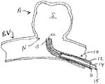
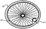
도 1은 혈관의 동맥류의 경부에 위치된 신규한 카테터 전달 시스템 내의 본 발명의 폐색 장치의 개략적인 측단면도.
도 2는 수축 상태로 유지되는 폐색 장치를 도시한 도 1의 전달 시스템의 개략적인 확대 측면도.
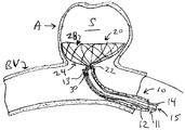
도 3은 전달 시스템에 의해 여전히 고정되어 유지되면서 동맥류의 낭 내에서 확장되는 본 발명에 따른 폐색 장치를 도시한 도 1과 유사한 개략적인 측면도.
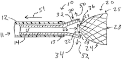
도 4는 전달 시스템 및 폐색 장치를 통해 동맥류 내로 전진되는 색전 코일을 도시한 도 3과 유사한 개략적인 측면도.
도 5는 그래스퍼 핑거(grasper finger)가 폐색 장치의 제어 링을 해제시키도록 허용하기 위해 마이크로카테터(microcatheter)가 근위방향으로 후퇴된 도 2와 유사한 개략적인 측면도.
도 6은 전달 시스템이 후퇴된 후의 그리고 색전 코일이 폐색 장치를 동맥류의 낭 내에 고정시키는 도 4와 유사한 개략적인 측단면도.
도 7은 본 발명에 따른 적어도 하나의 폐색 장치에 대한 제1 확장 상태를 확립하는 구형 맨드릴(spherical mandrel)의 개략적인 단면도.
도 8a 및 도 8b는 도 7의 폐색 장치로부터 얻어진 본 발명에 따른 2개의 반구형(hemi-spherical) 폐색 장치의 개략적인 측면도.
도 9는 도 7의 맨드릴이 제거된 후의 단일 폐색 장치의 개략적인 측면도.
도 10은 폐색 장치의 원위 부분이 제거되어 대안적인 개방 구성을 생성한 후의 도 9와 유사한 개략적인 측면도.
도 11은 타원형, 마름모꼴(lozenge)-형상의 맨드릴을 이용하여 형성된 대안적인 폐색 장치의 도 10과 유사한 측면도.
도 12는 동맥류 내의 케이지-유사 혈관-폐색 구조체와 협동하는 폐색 장치를 도시한 도 3과 유사한 도면.
도 13은 수축 상태로 유지되는 폐색 장치 및 혈관-폐색 구조체가 동맥류 내로 전진되는 도 12에 도시된 것과 유사한 장치를 위한 대안적인 전달 시스템의 개략적인 확대 측면도.
도 14는 전달 시스템이 후퇴된 후의 그리고 혈관-폐색 구조체가 폐색 장치를 동맥류의 낭 내에 고정시키는 도 13과 유사한 개략적인 측단면도.
도 15는 혈관의 동맥류의 경부에 위치된 신규한 카테터 전달 시스템 내의 본 발명의 폐색 장치 및 동맥류 낭 내로 삽입된 색전 장치를 전달하기 위한 카테터의 개략적인 측단면도.
도 16은 부분적으로 이식된 상태로 혈관의 동맥류의 경부에 위치된 도 15의 폐색 장치 및 동맥류 낭 내로 삽입된 색전 장치를 전달하기 위한 카테터를 도시한 개략적인 측단면도.
도 17a는 전달 시스템에 의해 여전히 고정되어 유지되면서 동맥류의 낭 내에서 확장되는 도 16의 폐색 장치 및 확장된 폐색 장치와 동맥류의 벽 사이에 구속된 색전 장치를 전달하기 위한 카테터를 도시한 개략적인 측면도.
도 17b는 도 17a의 확장된 폐색 장치 및 구속된 카테터의 단면도.
도 18은 도 17a의 확장된 폐색 장치 및 색전 전달 카테터 및 폐색 장치를 통해 동맥류 내로 전진되는 색전 코일을 도시한 개략적인 측면도.
도 19는 이식의 완료 및 카테터의 제거 후의 도 18의 확장된 폐색 장치를 도시한 개략적인 측면도.
도 20은 도 15 내지 도 19에 예시된 폐색 장치와 같은 확장된 폐색 장치의 해제를 도시한 개략적인 측면도.In the following, preferred embodiments of the present invention are described in more detail with reference to drawings and photographs.
1 is a schematic side cross-sectional view of the occlusion device of the present invention in a novel catheter delivery system located in the neck of an aneurysm of a blood vessel.
FIG. 2 is a schematic enlarged side view of the delivery system of FIG. 1 showing the occlusion device maintained in a retracted state.
FIG. 3 is a schematic side view similar to FIG. 1 showing the occlusion device according to the present invention extending within the sac of an aneurysm while still being held fixed by the delivery system.
FIG. 4 is a schematic side view similar to FIG. 3 showing the embolic coil advanced into the aneurysm through the delivery system and occlusion device.
Fig. 5 is a schematic side view similar to Fig. 2 in which the microcatheter is retracted proximally to allow the grasper finger to release the control ring of the occlusion device.
Fig. 6 is a schematic side cross-sectional view similar to Fig. 4 after the delivery system is retracted and the embolic coil secures the occlusion device in the sac of the aneurysm.
7 is a schematic cross-sectional view of a spherical mandrel establishing a first extended state for at least one occlusion device according to the present invention.
8A and 8B are schematic side views of two hemi-spherical occlusion devices according to the present invention obtained from the occlusion device of FIG. 7.
9 is a schematic side view of a single occlusion device after the mandrel of FIG. 7 is removed.
10 is a schematic side view similar to FIG. 9 after the distal portion of the occlusion device has been removed to create an alternative open configuration.
11 is a side view similar to FIG. 10 of an alternative occlusion device formed using an oval, lozenge-shaped mandrel.
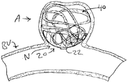
FIG. 12 is a view similar to FIG. 3 showing an occlusion device cooperating with a cage-like blood vessel-occlusion structure in an aneurysm.
FIG. 13 is a schematic enlarged side view of an alternative delivery system for a device similar to that shown in FIG. 12 in which the occlusion device maintained in a contracted state and the vasculature-occlusive structure are advanced into the aneurysm.
14 is a schematic lateral cross-sectional view similar to FIG. 13 after the delivery system is retracted and the vascular-occlusive structure secures the occlusive device within the sac of the aneurysm.
15 is a schematic side cross-sectional view of a catheter for delivering an occlusion device of the present invention and an embolic device inserted into an aneurysm sac in a novel catheter delivery system located in the neck of an aneurysm of a blood vessel.
FIG. 16 is a schematic cross-sectional side view of the occlusion device of FIG. 15 located in the cervical region of the aneurysm of the blood vessel in a partially implanted state and a catheter for delivering the embolic device inserted into the aneurysm sac.
FIG. 17A is a schematic side view of the occlusion device of FIG. 16 extending within the sac of an aneurysm and a catheter for delivering a constrained embolic device between the wall of the aneurysm and the occlusion device of FIG. .
17B is a cross-sectional view of the expanded occlusion device and constrained catheter of FIG. 17A.
18 is a schematic side view of the embolic coil advanced into the aneurysm through the expanded occlusion device and embolization delivery catheter and occlusion device of FIG. 17A.
FIG. 19 is a schematic side view showing the enlarged occlusion device of FIG. 18 after completion of implantation and removal of the catheter.
20 is a schematic side view showing the release of an extended occlusion device, such as the occlusion device illustrated in FIGS. 15 to 19.
본 발명은 제1 확장 상태 및 제2 수축 상태를 갖는, 근위 단부 영역 및 원위 단부 영역을 갖는 실질적으로 튜브형 구조체를 구비한, 환자 내의 혈관 내의 동맥류의 혈관내 치료에 적합한 폐색 장치에 의해 달성될 수 있다. 장치는 마이크로카테터와 같은 카테터를 이용한, 환자의 혈관구조를 통한, 그리고 동맥류의 경부를 통한 삽입에 적합한 제2 수축 상태에서의 치수를 갖는다. 장치는, 구조체의 근위 단부 영역 상에 배치되는 실질적으로 환형 본체를 갖고 근위 단부 영역의 반경방향 확장을 방지하기 위해 그리고 폐색 장치의 조작 중에 맞물림 특징부를 제공하기 위해 근위 단부 영역을 적어도 실질적으로 둘러싸는 제어 링을 추가로 포함한다.The present invention can be achieved by an occlusion device suitable for intravascular treatment of an aneurysm in a blood vessel in a patient, having a substantially tubular structure having a proximal end region and a distal end region, with a first expanded state and a second contracted state. have. The device has dimensions in a second contraction state suitable for insertion through the patient's vasculature and through the neck of the aneurysm, using a catheter such as a microcatheter. The device has a substantially annular body disposed on the proximal end area of the structure and at least substantially surrounds the proximal end area to prevent radial expansion of the proximal end area and to provide engagement features during operation of the occlusion device. It further includes a control ring.
제어 링은 몇몇 기계적 구성에서 전달 부재 상의 그래버 또는 적어도 하나의 취약 부재(frangible member)와 같은 해제가능 특징부에 의해, 또는 다른 구성에서 적어도 하나의 전해 절단가능 요소(electrolytically severable element)에 의해 해제가능하게 맞물릴 수 있다. 바람직하게는, 제어 링은 내측 통로를 한정하고, 내측 통로를 통해 적어도 하나의 색전 코일이 동맥류 내로 삽입가능하다. 다른 구성에서, 폐색 장치는 케이지-유사 장치와 같은 적어도 하나의 혈관-폐색 구조체에 의해 동맥류 내에서 제위치로 유지된다.The control ring is releasable by a releasable feature such as a grabber or at least one frangible member on a transmission member in some mechanical configurations, or by at least one electrolytically severable element in other configurations. Can be engaged. Preferably, the control ring defines an inner passageway, through which at least one embolic coil is insertable into the aneurysm. In another configuration, the occlusion device is held in place within the aneurysm by at least one vascular-occlusion structure, such as a cage-like device.
도 1은 혈관(BV)으로부터 나오는 동맥류(A)의 낭(S) 내에 이식될 본 발명에 따른 튜브형 폐색 장치(20)를 유지시키는 전달 튜브(14) 및 마이크로카테터(12)를 포함하는 신규한 전달 시스템(10)의 원위 부분을 개략적으로 예시한다. 일 구성에서, 마이크로카테터(12)는 원위 방사선 불투과성 마커 밴드(radiopaque marker band)(13)를 구비하고, 형광투시법(fluoroscopy) 하에서 볼 때 마커 밴드(13)가 경부(N)의 레벨에 있도록 동맥류(A)의 경부(N) 부근으로 전진된다.1 is a novel comprising a
전달 시스템(10)의 원위 부분 및 폐색 장치(20)의 확대도가 도 2 및 도 5에 제공된다. 폐색 장치(20)는 제어 링(22)이 전달 튜브(14)의 그래버(30)에 의해 유지되는 상태로, 카테터 루멘(11) 내에서 도 2에 제2 수축 상태로 도시된다. 제어 링(22)은 더욱 상세히 후술되는 바와 같이, 장치 구조체(25)의 근위 영역(23) 주위에 배치되고 내측 통로(26)를 한정하며, 내측 통로를 통해 하나 이상의 색전 코일이 삽입된다. 폐색 장치(20)의 구조체(25)는 메시 본체(mesh body)(24) 및 원위 영역(28)을 추가로 포함한다.2 and 5 are enlarged views of the distal portion of the
전달 시스템(10)이 도 1에 도시된 바와 같이 위치된 후에, 도 3에 도시된 바와 같이 전달 튜브(14)가 카테터(12)의 루멘(11) 내에서 전진되어 폐색 장치(20)가 낭(S) 내에서 대략 반구형 형상으로 확장될 수 있게 한다. 폐색 장치(20)의 형상은 장치(20)가 낭(S)의 내벽과 접촉하는 곳에서 낭(S)의 형상에 정합할 것이다. 그래버(30)는 카테터(12)의 루멘(11)에 의해 계속 반경방향으로 구속되고, 도 5의 노치(36, 38)와 같은 복수의 파지 영역으로 제어 링(22)에 대한 그의 파지를 유지시킨다. 일 구성에서, 제어 링(22)은 방사선 불투과성이고, 도 3 및 도 4에 도시된 바와 같이 형광투시법 하에서 카테터(12) 상의 마커(13)에 대해 정렬된다.After the
일단 폐색 장치(20)가 낭(S) 내에 위치되면, 도 4의 적어도 하나의 색전 코일(40)이 화살표(42)에 의해 표시된 바와 같이 전달 튜브(14)의 루멘(15)을 통해, 화살표(44)에 의해 표시된 바와 같이 제어 링(22)의 통로(26)를 통해 전진되고, 화살표(46)에 의해 표시된 바와 같이 동맥류(A) 내에서 전진되어, 도 6에 도시된 바와 같이 낭(S)을 실질적으로 충전하고 폐색 장치(20)의 본체(24)를 동맥류(A)의 내벽에 맞대어 고정시켜 경부(N)를 차단한다.Once the
충분한 양의 색전 코일(40)이 낭(S) 내에 완전히 전개되어 동맥류(A) 내에 폐색 장치(20)를 고정시킨 후에, 전달 튜브(14)를 제위치로 유지시킨 상태에서, 도 5에 화살표(51)에 의해 표시된 바와 같이, 카테터(12)가 근위방향으로 후퇴되어, 그래버(30)의 핑거(32, 34)에 대한 반경방향 구속을 제거한다. 핑거(32, 34)는 바람직하게는 각각 반경방향 외향으로 편향되고 화살표(50, 52)의 방향으로 이동하여, 각각 핑거(32, 34) 내의 노치(36, 38)로부터 제어 링(22)을 분리시킨다.After a sufficient amount of the
일 구성에서, 카테터(12)는 0.020 인치 내지 0.027 인치의 내경을 갖는 내측 루멘(11)을 한정하는 중합체 마이크로카테터이며, 전달 튜브(14)는 카테터 루멘(11)의 내경보다 약간 작은 외경을 갖고, 폐색 장치(20)가 도 1 및 도 2에 도시된 수축 상태에 있는 그래버(30)가 또한 카테터 루멘(11)의 내경과 실질적으로 동일한 외경을 가지며, 이는 핑거(32, 34)를 제어 링(22)과 맞물리도록 반경방향으로 구속한다. 전달 튜브(14)의 루멘(15)은 0.010 인치 내지 0.015 인치의 공칭 외경을 갖는 종래의 색전 코일 전달 시스템의 통과를 허용할 수 있는 직경을 갖는다.In one configuration, the
몇몇 구성에서, 전달 튜브는 마이크로카테터에 대한 전달 튜브의 병진 중에 의도하지 않은 마이크로카테터 이동을 최소화시키기 위해, 특히 전달 튜브의 원위 단부 부근에서, 증가된 가요성의 적어도 하나의 영역을 구비한다. 적어도 하나의 가요성 영역은 일 구성에서 의료용 니티놀(NiTi) 튜브 내에 단속 커팅부(interrupted cut)의 패턴을 레이저-커팅함으로써 제조된다. 다른 구성에서, 코일형 금속 또는 중합체 원통형 구성요소 및/또는 가요성 중합체 재료의 원통형 섹션이 전달 튜브의 원위 영역에 추가된다. 그래버는 몇몇 구성에서, 각각이 바람직하게는 본 발명에 따른 제어 링의 파지를 향상시키기 위한 노치를 구비하는 적어도 2개의 핑거 요소를 생성하도록 그래버를 형성하는 재료를 레이저-커팅함으로써 생성된다. 소정 구성에서, 그래버는 일체형이며, 즉 전달 튜브의 나머지와 동일한 재료로 단일체로 형성되며, 다른 구성에서는, 전달 튜브의 원위 단부에 고정식으로 부착된다.In some configurations, the delivery tube has at least one area of increased flexibility to minimize unintentional microcatheter movement during translation of the delivery tube to the microcatheter, particularly near the distal end of the delivery tube. The at least one flexible region is made by laser-cutting a pattern of interrupted cuts in a medical NiTiol tube in one configuration. In other configurations, coiled metal or polymeric cylindrical components and / or cylindrical sections of flexible polymeric material are added to the distal region of the delivery tube. The grabber, in some configurations, is preferably produced by laser-cutting the material forming the grabber to create at least two finger elements, each with a notch for enhancing gripping of the control ring according to the invention. In some configurations, the grabbers are integral, ie formed integrally from the same material as the rest of the delivery tube, and in other configurations, fixedly attached to the distal end of the delivery tube.
일 구성에서, 폐색 장치(20)의 구조체(25)는 확장가능 편조 메시 튜브(braided mesh tube)를 확립하는 금속 필라멘트(filament)로 형성된다. 필라멘트에 적합한 재료는 니티놀 와이어, 및 전달 튜브로부터 방출된 후에 수축 상태로 유지되지 않을, 백금과 같은 다른 생체적합성 금속을 포함한다. 바람직하게는, 적어도 하나의 백금 와이어가 방사선 불투과성을 위해 포함된다. 다른 구성에서, 구조체(25)는 수축 상태에서 "경화"되지 않는 적어도 하나의 중합체 재료로 형성된다.In one configuration, the
위에서 논의된 제어 링(22)에, 그리고 도 7 내지 도 8b에 관하여 아래에서 논의되는 제어 링(22a) 및 밴드(22b)에 적합한 재료는 백금, 탄탈륨 및 금과 같은 생체적합성 방사선 불투과성 재료를 포함한다. 다른 적합한 금속 재료는 코발트 크롬, 스테인리스 강, 및 생체적합성 금속 중 둘 이상의 조합을 포함한다. 적합한 중합체 재료는 더욱 상세히 후술되는 바와 같이, 생체적합성 생분해성 및 비-생분해성 재료를 포함한다.Suitable materials for the
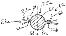
본 발명에 따른 폐색 장치를 제조하기 위한 하나의 기술이 도 7에 예시된다. 구조체(25a)가 편조 메시 튜브로서 형성된 후에, 전술된 바와 같이, 근위 영역(23a) 주위에 링 재료를 크림핑(crimping) 및/또는 용접하여 그러한 위치에서의 반경방향 확장을 제한하면서 하나 이상의 색전 코일이 그것을 통해 삽입될 수 있는 내측 통로(26a)를 한정함으로써 제어 링(22a)이 배치된다. 선택적으로, 그로밋(grommet)(도시되지 않음)과 같은 내측 슬리브가 구조체(25a) 내로 삽입되고 제어 링(23a) 아래에 위치되어 내측 통로(26a)를 위한 원하는 치수의 내경 개구를 유지시킨다.One technique for manufacturing the occlusion device according to the invention is illustrated in FIG. 7. After the
이러한 기술에서, 강재 볼 베어링(steel ball bearing)과 같은 구형 맨드릴(60)이 원위 영역(28a)을 통해 삽입되어 본체 영역(24a)에서 구조체(25a)를 확대 및 확장시킨다. 밴드(22b)와 같은 클램프-유사(clamp-like) 요소가 이어서 원위 영역(62) 위에 크림핑되어 본체(24a)를 추가로 형상화시킨다. 몇몇 기술에서, 조립체는 확장 상태에서 메시 본체(24a)를 경화시키기 위해 가열된다.In this technique, a spherical mandrel 60, such as a steel ball bearing, is inserted through the distal region 28a to enlarge and expand the
2개의 반구형 폐색 장치가 요구될 때, 파선(63)에 의해 표시된 바와 같이 전형적으로 제어 링(22a)과 밴드(22b) 사이에서 등거리로 맨드릴(60)의 원주를 따라, 그리고 각각 화살표(64, 66)에 의해 도시된 바와 같이 제어 링(22a)과 밴드(22b)의 서로 반대편에 있는 측부들 상에서 커팅이 행해진다. 이러한 기술은 각각 도 8a 및 도 8b에 도시된 바와 같이, 2개의 별개의 장치(20a, 20b)를 생성한다. 예를 들어 도 1 내지 도 6의 장치(20)에 대해 예시된 바와 같이, 원위 단부 영역(28a, 28b)은 둘 모두 개방된다. 장치(20b)가 또한 본체(24b), 근위 영역(23b), 및 본 발명에 따른 제어 링의 역할을 하는 밴드(22b)에 의해 형성되는 통로(26b)를 구비한다. 바꾸어 말하면, 밴드(22b)는 임시 클램프가 아니라, 일 구성에서 이식가능 장치(20b) 내에 통합된다.When two hemispherical occlusion devices are required, typically along the circumference of the mandrel 60 at equal distances between the
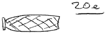
대안적인 기술에서, 밴드(22b)가 제거되고, 도 7의 맨드릴(60)이 추출되어, 단일 제어 링(22a)을 갖는, 조여지지만 구속되지 않은 원위 영역(28c)을 구비한, 도 9의 폐색 장치(20c)를 형성한다. 또 다른 기술에서, 커팅이 구조체(25a) 주위로 비-적도방향으로(non-equatorially), 예컨대 선(70)을 따라 행해져, 도 10의 장치(20d)를 생성한다. 또 다른 구성에서, 마름모꼴-형상의 맨드릴과 같은 비-구형 맨드릴이 도 11의 긴 장치(20e)를 형성하기 위해 이용된다. 바꾸어 말하면, 본 발명에 따른 폐색 장치는 둥근형, 타원형, 장방형, 또는 다른 비대칭형과 같은 많은 형상을 가질 수 있고, 개방 또는 폐쇄 원위 단부를 구비할 수 있다. 개방 원위 단부가 전형적으로 치료될 동맥류의 경부 및 낭에 대한 보다 양호한 정합을 허용할 것으로 예상된다.In an alternative technique, the band 22b is removed, and the mandrel 60 of FIG. 7 is extracted, with a tightened but unconstrained distal region 28c having a
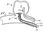
이러한 구성에서 스트랜드(82, 84, 86, 88, 90, 92, 94)로 형성된 케이지-유사 혈관-폐색 구조체(80)와 협동하는 본 발명에 따른 대안적인 폐색 장치(20f)가 도 12에 예시된다. 몇몇 구성에서, 혈관-폐색 구조체(80)는 호튼에 의한 미국 특허 제5,645,558호에 개시된 실시예 중 하나와 유사하고, 소정의 다른 구성에서, 굴리엘미에 의한 미국 특허 제5,916,235호 및 베즈네다로글루 등에 의한 미국 특허 공개 제2010/0069948호에 개시된 실시예 중 하나와 유사하다.An alternative occlusion device 20f in accordance with the present invention cooperating with a cage-like vascular-
전달 시스템(10f)이 동맥류(A)에 대해 원하는 대로 위치된 후에, 도 12에 도시된 바와 같이, 긴 전달 부재(14f)가 카테터(12f)의 루멘(11f) 내에서 전진되어 폐색 장치(20f) 및 혈관-폐색 구조체(80)가 낭(S) 내에서 확장될 수 있게 한다. 이러한 구성에서, 그래버(30f)가 카테터(12f)의 루멘(11f)에 의해 계속 반경방향으로 구속되고, 복수의 파지 영역으로 제어 링(22f)에 대한 그의 파지를 유지시킨다. 일 구성에서, 제어 링(22f)은 방사선 불투과성이고, 도 3 및 도 4에 대해 전술된 바와 유사한 방식으로 형광투시법 하에서 정렬된다.After the delivery system 10f is positioned as desired relative to the aneurysm A, a long delivery member 14f is advanced within the lumen 11f of the catheter 12f, as shown in FIG. 12, to occlude the device 20f ) And the vascular-
일단 혈관-폐색 구조체(80)가 낭(S) 내에서 확장 상태로 완전히 전개되면, 구조체(80)가 폐색 장치(20f)를 내벽에 맞대어 그리고 동맥류(A)의 경부(N)를 가로질러 가압하여 그것을 제위치로 고정시킨다. 바꾸어 말하면, 혈관-폐색 구조체(80)는 확장 상태에서 폐색 장치(20f)를 경부(N)에 맞대어 고정시키기 위한 프레임 또는 격자의 역할을 하고, 구조체(80)에 의해 제위치로 유지되는 폐색 장치(20f)는 적어도 경부(N)를 가로질러 연장되는 커버의 역할을 하며, 커버는 바람직하게는 동맥류(A)의 폐색을 향상시키기 위해 다공성이거나 달리 충분히 작은 개구를 한정한다. 바람직하게는, 폐색 장치(20f)는 특히 전달 캐뉼러(delivery cannula)를 이용한 구조체(80) 및 장치(20f)의 로딩(loading) 및 전달 중에, 장치(20f)와 구조체(80) 사이의 정렬된 관계를 유지시키기 위해, 장치(20f)의 내부 표면의 일부분 및 제어 링(22f)의 일부분 중 적어도 하나에 부착되는 적어도 하나의 부착 지점에 의해 혈관-폐색 구조체(80)에 고정된다.Once the vascular-
소정 기술에서, 외과의사 또는 다른 사용자가 낭(S)의 내부를 실질적으로 충전하기를 원하면, 적어도 하나의 색전 코일이 전달 튜브(14f)의 루멘(15f)을 통해, 제어 링(22f) 내의 통로를 통해 전진되고, 이어서 동맥류(A) 내로 전진된다. 다른 구성에서, 하나 이상의 색전 코일의 삽입이 요구되지 않는 사용을 위해, 제어 링(22f)에는 통로가 없을 수 있다.In certain techniques, if a surgeon or other user wishes to substantially fill the interior of the sac S, at least one embolic coil passes through the lumen 15f of the delivery tube 14f, a passage in the control ring 22f Through, and then into the aneurysm (A). In other configurations, for use where insertion of one or more embolic coils is not required, the control ring 22f may be free of passages.
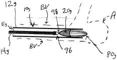
도 13 및 도 14에 예시된 것과 같은 또 다른 구성에서, 폐색 장치(20g)는 제어 링 대신에 종래의 탈착 조인트(detachment joint)를 나타내는 탈착 특징부(98)를 구비한다. 전해 절단가능 조인트 및 기계식 조인트의 예가 예를 들어 월리스에 의한 미국 특허 제6,454,780호 및 머피 등에 의한 미국 특허 제7,410,482호에 기술된다. 유사한 탈착가능 조인트가 케이지-유사 혈관-폐색 구조체에 대해 굴리엘미에 의한 미국 특허 제5,916,235호에 기술된다.In another configuration, such as illustrated in Figures 13 and 14, the occlusion device 20g has a
도 13에 도시된 바와 같이 전달 시스템(10g)이 혈관(BV) 내에 위치된 후에, 도 14에 도시된 바와 같이, 또한 푸셔(pusher)(14g)로 지칭되는 전달 부재(14g)가 카테터(12g)의 루멘(11g) 내에서 전진되어 폐색 장치(20g) 및 혈관-폐색 구조체(80g)가 동맥류(A) 내에서 확장될 수 있게 한다. 이어서, 절단가능 요소(96)와 탈착 특징부(98) 사이의 연결부가 기계식으로 및/또는 전해식으로 절단된다.After the delivery system 10g is positioned in the blood vessel BV as shown in FIG. 13, as shown in FIG. 14, the delivery member 14g, also referred to as a pusher 14g, is a catheter 12g ) Within the lumen (11 g) to allow the occlusion device (20 g) and the vascular-occlusion structure (80 g) to expand within the aneurysm (A). The connection between the
본체(24g)는 몇몇 구성에서 와이어 메시(wire mesh) 또는 편조물(braid)로 형성된다. 또 다른 구성에서, 폐색 장치의 본체는 하나 이상의 중합체 물질로부터 제조되는 생체적합성 필름이다. 필름 재료에 적합한 생체적합성 조성물은 셀룰로오스, 알지네이트, 가교-결합 겔의 필름 또는 매트릭스, 및 우레탄, 폴리카프로락톤(PCL), 폴리-락트산(PLA) 및/또는 폴리-글리콜산(PGA)과 같은 재료의 매우 얇은 중합체 필름을 포함한다. 필름은 침식성 또는 생체흡수성일 필요가 없다. 몇몇 구성에서, 몇몇 구성에서는 균일하고 다른 구성에서는 불균일한 평균 직경을 갖는 미세 기공(microscopic pore) 또는 다른 개구가 필름 내에 형성된다. 기공의 기하학적 크기는 몇몇 실시예에서는 구조체의 길이를 따라 실질적으로 일정하고, 다른 실시예에서는 길이를 따라 변화한다. 기공의 개수는 몇몇 실시예에서는 구조체의 길이를 따라 실질적으로 균일하고, 다른 실시예에서는 길이를 따라 변화한다. 다른 잠재적인 재료는 다당류, 콜로이드 화합물, 및 몇몇 지질 생성물을 포함한다. 대안적인 구성에서, 적어도 폐색 장치의 본체는 고화 우레탄 발포체 또는 확장 폴리테트라플루오로에틸렌(PTFE)과 같은 내구성, 비-침식성, 비-생체흡수성 재료로 제조된다. 몇몇 실시예에서, 재료는 환자 내에 이식하기 전에 직경이 10 마이크로미터 이상인 개구를 한정하고, 범위가 10 마이크로미터 내지 500 마이크로미터인 두께를 갖는다.The body 24g is formed of a wire mesh or braid in some configurations. In another configuration, the body of the occlusion device is a biocompatible film made from one or more polymeric materials. Suitable biocompatible compositions for the film material are films or matrices of cellulose, alginate, cross-linked gels, and materials such as urethane, polycaprolactone (PCL), poly-lactic acid (PLA) and / or poly-glycolic acid (PGA). It contains a very thin polymer film. The film need not be erosive or bioabsorbable. In some configurations, microscopic pores or other openings with uniform average diameter in some configurations and non-uniform in other configurations are formed in the film. The geometric size of the pores is substantially constant along the length of the structure in some embodiments and varies along the length in other embodiments. The number of pores is substantially uniform along the length of the structure in some embodiments and varies along the length in other embodiments. Other potential materials include polysaccharides, colloidal compounds, and some lipid products. In an alternative configuration, at least the body of the occluding device is made of a durable, non-erodible, non-bioabsorbable material such as solidified urethane foam or expanded polytetrafluoroethylene (PTFE). In some embodiments, the material defines an aperture of 10 micrometers or more in diameter before implanting into the patient, and has a thickness ranging from 10 micrometers to 500 micrometers.
도 15는 폐색 장치 전달 카테터(12h), 튜브형 폐색 장치(20h)를 유지시키는, 폐색 장치 전달 카테터(12h)의 루멘(11h) 내에 위치되는 전달 튜브(14h), 및 본 발명에 따른 색전 임플란트 전달 카테터(41h)를 포함하는 신규한 전달 시스템(10h)의 원위 부분을 개략적으로 예시한다. 예시된 바와 같이, 색전 임플란트 전달 카테터(41h)는 폐색 장치(20h)와 별도로 동맥류(A)로 전달될 수 있다. 색전 임플란트 전달 카테터(41h)의 원위 단부가 동맥류(A)의 낭(S) 내로 삽입될 수 있고, 폐색 장치 전달 카테터(12h)가 폐색 장치(20h)를 동맥류(A)의 낭(S) 내에 이식하도록 위치될 수 있다. 일 구성에서, 마이크로카테터(12h)는 원위 방사선 불투과성 마커 밴드(13h)를 구비하고, 형광투시법 하에서 볼 때 마커 밴드(13h)가 경부(N)의 레벨에 있도록 동맥류(A)의 경부(N) 부근으로 전진된다.15 is a
전달 시스템(10h)이 도 15에 도시된 바와 같이 위치된 후에, 전달 부재(14h)가 카테터(12h)의 루멘(11h) 내에서 전진되어 폐색 장치(20h)가 낭(S) 내에서 대략 반구형 형상으로 확장될 수 있게 한다. 도 16은 폐색 장치가 폐색 장치 전달 카테터(12h)로부터 빠져나갈 때 폐색 장치(20h)의 원위 단부 영역(28h)의 확장을 예시한다. 도 17a는 폐색 장치(20h)의 외부 표면이 동맥류(A) 및 색전 임플란트 전달 카테터(41h)와 접촉하도록 확장된 폐색 장치(20h)의 튜브형 본체 영역(24h)을 예시한다. 폐색 장치(20h)의 형상은 장치(20h)가 낭(S)의 내벽과 접촉하는 곳에서 낭(S)의 형상에 정합할 것이고, 장치(20h)가 색전 카테터(41h)와 접촉하는 곳에서 색전 임플란트 전달 카테터(41h)에 정합할 것이다. 도 17b는 낭(S)의 내벽 및 색전 임플란트 전달 카테터(41h)에 대한 장치(20h)의 정합을 예시한 도 17a의 단면도이다. 폐색 장치(20h)의 본체 영역(24h)은 확장 상태에서 색전 카테터(41h)를 동맥류 벽과 병치시키는(appose) 힘을 제공한다.After the
일단 폐색 장치(20h)가 낭(S) 내에 위치되면, 도 18의 적어도 하나의 색전 코일(40h)이 색전 임플란트 전달 카테터(41h)의 루멘을 통해 전진되어, 도 19에 도시된 바와 같이 낭(S)을 실질적으로 충전하고 폐색 장치(20h)의 본체(24h)를 동맥류(A)의 내벽에 맞대어 고정시켜 경부(N)를 차단한다. 명백한 바와 같이, 일단 색전 코일(40h)이 전달되면, 색전 임플란트 전달 카테터(41h)가 제거될 수 있다. 일단 낭(S)으로부터 제거되면, 폐색 장치(20h)가 내벽의 나머지 섹션에 정합할 수 있다.Once the
집합적으로 도 15 내지 도 18을 참조하면, 폐색 장치(20h) 및 색전 코일(40h)의 이식 중에, 폐색 장치(20h)의 근위 단부 영역(23h) 부근의 제어 링(22h)이 전달 부재(14h) 상의 그래버(30h)에 의해 유지될 수 있다. 충분한 양의 색전 코일(40h)이 낭(S) 내에 완전히 전개되어 동맥류(A) 내에 폐색 장치(20h)를 고정시킨 후에, 폐색 장치(14h)가 전달 부재(14h)로부터 해제될 수 있다. 그래버(30h)는 폐색 장치 전달 카테터(12h)에 의해 구속될 수 있고, 도 20에 도시된 바와 같이 그래버(30h)의 핑거(32h, 34h)가 폐색 장치 전달 카테터(12h)로부터 빠져나갈 때 확장되어 제어 링(22h)을 해제시킬 수 있다. 그래버(30h)는 노치(36h, 38h)와 같은 복수의 파지 영역을 구비할 수 있다. 일 구성에서, 제어 링(22h)은 방사선 불투과성이고, 도 15 내지 도 18 및 도 20에 도시된 바와 같이 형광투시법 하에서 카테터(12h) 상의 마커(13h)에 대해 정렬된다. 핑거(32h, 34)는 바람직하게는 반경방향 외향으로 편향되어 각각 핑거(32h, 34h) 내의 노치(36h, 38h)로부터 제어 링(22h)을 분리시킨다.Referring collectively to FIGS. 15 to 18, during the implantation of the
도 15 내지 도 20에 예시된 시스템(10h)의 이점은 폐색 장치 전달 카테터(12h), 제어 링(22h), 및 전달 부재(14h)가 색전 임플란트를 전달하도록 크기설정될 필요가 없다는 것이다. 전달 부재(14h)가 색전 임플란트를 전달하도록 크기설정될 필요가 없기 때문에, 다수의 대안적인 전달 또는 푸셔 장치가 본 명세서에 기술된 전달 부재 및 전달 튜브 대신에 또는 그것에 더하여 사용될 수 있다.The advantage of the
일 구성에서, 폐색 장치(20h)의 튜브형 구조체, 즉 메시 본체 영역(24h)은 확장가능 편조 메시 튜브를 확립하는 금속 필라멘트로 형성된다. 필라멘트에 적합한 재료는 니티놀 와이어, 및 전달 튜브로부터 방출된 후에 수축 상태로 유지되지 않을, 백금과 같은 다른 생체적합성 금속을 포함한다. 바람직하게는, 적어도 하나의 백금 와이어가 방사선 불투과성을 위해 포함된다. 다른 구성에서, 튜브형 구조체(24h)는 수축 상태에서 "경화"되지 않는 적어도 하나의 중합체 재료로 형성된다.In one configuration, the tubular structure of
이와 같이, 그의 바람직한 실시예에 적용되는 바와 같은 본 발명의 근본적이고 신규한 특징이 도시되고, 기술되고, 지적되었지만, 본 발명의 사상 및 범주로부터 벗어남이 없이, 예시된 장치의 형태 및 상세에서, 그리고 그들의 작동에서 다양한 생략, 대체, 및 변경이 당업자에 의해 이루어질 수 있는 것이 이해될 것이다. 예를 들어, 동일한 결과를 달성하기 위해 실질적으로 동일한 방식으로 실질적으로 동일한 기능을 수행하는 이들 요소 및/또는 단계의 모든 조합이 본 발명의 범주 내에 있는 것으로 명백히 의도된다. 하나의 기술된 실시예로부터 다른 실시예로의 요소의 대체가 또한 충분히 의도되고 고려된다. 도면은 반드시 일정한 축척으로 작성되지는 않으며 도면은 단지 본질적으로 개념적인 것임이 또한 이해되어야 한다. 따라서, 본 명세서에 첨부된 청구범위의 범주에 의해 나타내어지는 것으로만 제한되도록 의도된다.As such, while the underlying and novel features of the present invention have been illustrated, described and pointed out as applied to its preferred embodiments, in the form and detail of the illustrated device, without departing from the spirit and scope of the invention, And it will be understood that various omissions, substitutions, and changes in their operation can be made by those skilled in the art. For example, it is expressly intended that all combinations of these elements and / or steps that perform substantially the same function in substantially the same way to achieve the same result are within the scope of the present invention. Substitution of elements from one described embodiment to another is also fully intended and contemplated. It should also be understood that the drawings are not necessarily drawn to scale, and that the drawings are merely conceptual in nature. Accordingly, it is intended to be limited only to those indicated by the scope of the claims appended hereto.
본 명세서에 인용된 모든 허여된 특허, 계류 중인 특허 출원, 간행물, 저널 기사, 서적 또는 임의의 다른 참고 문헌은 각각 전체적으로 참고로 포함된다.All issued patents, pending patent applications, publications, journal articles, books or any other references cited herein are incorporated by reference in their entirety.
Claims (20)
근위 단부 영역 및 원위 단부 영역을 갖는 실질적으로 튜브형 편조 메시 구조체(tubular braided mesh structure) 및 상기 튜브형 구조체의 상기 근위 단부 영역 상에 배치되는 실질적으로 환형 본체(annular body)를 갖는 제어 링(control ring)을 구비한 폐색 장치(occlusion device)로서, 상기 제어 링은 상기 근위 단부 영역의 반경방향 확장을 방지하기 위해 그리고 상기 폐색 장치의 조작 중에 맞물림 특징부를 제공하기 위해 상기 근위 단부 영역을 적어도 부분적으로 둘러싸는, 상기 폐색 장치; 및
상기 동맥류로 색전 임플란트(embolic implant)를 전달할 수 있는 색전 임플란트 전달 카테터(delivery catheter)를 포함하고,
상기 튜브형 구조체는 수축 상태(collapsed condition)로부터 확장 상태(expanded condition)로 확장가능하고,
상기 수축 상태에서, 상기 튜브형 구조체는 환자의 혈관구조를 통한 그리고 상기 동맥류의 경부(neck)를 통한 삽입에 적합하고,
상기 확장 상태에서, 상기 튜브형 구조체는 실질적으로 반구형 형상(hemispherical shape)을 갖고, 상기 동맥류와 접촉할 수 있는 그리고 상기 색전 임플란트 전달 카테터를 상기 동맥류와 병치시키는(appose) 힘을 제공할 수 있는 외부 표면을 갖는, 시스템.A system suitable for endovascular treatment of aneurysms in blood vessels in a patient,
A control ring having a substantially tubular braided mesh structure having a proximal end region and a distal end region and a substantially annular body disposed on the proximal end region of the tubular structure. An occlusion device having a control ring at least partially surrounding the proximal end area to prevent radial expansion of the proximal end area and to provide an engagement feature during operation of the occlusion device. , The occlusion device; And
An embolic implant delivery catheter capable of delivering an embolic implant to the aneurysm,
The tubular structure is expandable from a collapsed condition to an expanded condition,
In the contracted state, the tubular structure is suitable for insertion through the patient's vascular structure and through the neck of the aneurysm,
In the expanded state, the tubular structure has a substantially hemispherical shape, an external surface capable of contacting the aneurysm and providing force to embolize the embolic implant delivery catheter with the aneurysm. Having, system.
제1 확장 상태 및 폐색 장치 전달 카테터 내로 끌어당겨질 때의 제2 수축 상태를 갖는, 근위 단부 영역 및 원위 단부 영역을 갖는 실질적으로 튜브형 구조체를 포함하고, 상기 튜브형 구조체의 상기 근위 단부 영역 상에 배치되는 실질적으로 환형 본체를 갖고 상기 근위 단부 영역의 반경방향 확장을 방지하기 위해 상기 근위 단부 영역을 적어도 실질적으로 둘러싸는 제어 링을 추가로 포함하는, 폐색 장치를 선택하는 단계로서, 상기 튜브형 구조체는 편조 메시 튜브이고, 상기 튜브형 구조체는 상기 확장 상태에서 실질적으로 반구형 형상을 갖는, 상기 폐색 장치를 선택하는 단계;
상기 폐색 장치를 상기 수축 상태에 있게 하도록 상기 폐색 장치를 상기 폐색 장치 전달 카테터 내로 끌어당기는 단계;
색전 임플란트 전달 카테터의 원위 단부를 상기 동맥류 내로 삽입하는 단계;
상기 폐색 장치를 가진 상기 폐색 장치 전달 카테터를 상기 혈관 내의 상기 동맥류의 영역에 도달하도록 상기 환자의 혈관구조 내로 삽입하는 단계;
상기 색전 임플란트 전달 카테터를 상기 동맥류의 벽에 맞대어 포획시키기 위해 상기 폐색 장치를 확장시키는 단계;
상기 폐색 장치를 상기 동맥류 내에 위치시키는 단계; 및
상기 근위 단부 영역에서 상기 제어 링을 해제시키고 상기 폐색 장치 전달 카테터를 상기 환자로부터 후퇴시키는 단계를 포함하는, 방법.A method of treating an aneurysm in a blood vessel in a patient,
A substantially tubular structure having a proximal end region and a distal end region having a first expanded state and a second contracted state when pulled into the occlusion device delivery catheter, disposed on the proximal end area of the tubular structure Selecting an occlusion device having a substantially annular body and further comprising a control ring at least substantially surrounding the proximal end region to prevent radial expansion of the proximal end region, wherein the tubular structure is a braided mesh. Selecting the occlusion device, which is a tube, the tubular structure having a substantially hemispherical shape in the expanded state;
Pulling the occlusion device into the occlusion device delivery catheter so that the occlusion device is in the retracted state;
Inserting the distal end of the embolic implant delivery catheter into the aneurysm;
Inserting the occlusion device delivery catheter with the occlusion device into the vascular structure of the patient to reach an area of the aneurysm in the blood vessel;
Expanding the occlusion device to capture the embolic implant delivery catheter against the wall of the aneurysm;
Placing the occlusion device within the aneurysm; And
And releasing the control ring in the proximal end region and retracting the occlusion device delivery catheter from the patient.
제1 확장 상태 및 전달 마이크로카테터(delivery microcatheter) 내로 끌어당겨질 때의 제2 수축 상태를 갖는, 근위 단부 영역 및 원위 단부 영역을 갖는 실질적으로 튜브형 구조체를 포함하고, 상기 근위 단부 영역의 적어도 일부분이 상기 동맥류의 폐색을 향상시키기에 충분히 작은 크기를 갖는 복수의 개구들을 한정하고, 상기 튜브형 구조체의 상기 근위 단부 영역 상에 배치되는 실질적으로 환형 본체를 갖고 상기 근위 단부 영역의 반경방향 확장을 방지하기 위해 상기 근위 단부 영역을 적어도 실질적으로 둘러싸는 제어 링을 추가로 포함하는, 폐색 장치를 선택하는 단계로서, 상기 튜브형 구조체는 편조 메시 튜브이고, 상기 튜브형 구조체는 상기 확장 상태에서 실질적으로 반구형 형상을 갖는, 상기 폐색 장치를 선택하는 단계;
상기 폐색 장치의 조작을 가능하게 하도록 상기 제어 링을 푸셔 부재(pusher member) 상의 그래버와 기계적으로 맞물리게 하는 단계;
상기 폐색 장치를 상기 수축 상태에 있게 하도록 상기 폐색 장치를 상기 푸셔 부재를 보유하는 상기 전달 마이크로카테터 내로 끌어당기는 단계;
상기 폐색 장치를 가진 상기 전달 마이크로카테터를 상기 혈관 내의 상기 동맥류의 영역에 도달하도록 상기 환자의 혈관구조 내로 삽입하는 단계;
색전 임플란트 카테터의 원위 단부를 상기 동맥류 내로 삽입하는 단계;
상기 폐색 장치를 상기 동맥류 내에 위치시키는 단계;
상기 색전 임플란트 카테터를 상기 동맥류의 벽에 맞대어 포획시키기 위해 상기 폐색 장치를 확장시키는 단계;
상기 동맥류 내로의 혈류를 폐색시키기 위해 상기 색전 임플란트 카테터를 통해 적어도 하나의 색전 코일을 전달하는 단계; 및
상기 제어 링을 기계적으로 해제시키고 상기 전달 마이크로카테터 및 상기 색전 임플란트 카테터를 상기 환자로부터 후퇴시키는 단계를 포함하는, 방법.A method of treating an aneurysm in a blood vessel in a patient,
A substantially tubular structure having a proximal end region and a distal end region having a first expanded state and a second contracted state when drawn into a delivery microcatheter, wherein at least a portion of the proximal end region is To define a plurality of openings having a size small enough to improve occlusion of the aneurysm, and having a substantially annular body disposed on the proximal end region of the tubular structure to prevent radial expansion of the proximal end region Selecting an occlusion device, further comprising a control ring that at least substantially surrounds the proximal end region, wherein the tubular structure is a braided mesh tube, and the tubular structure has a substantially hemispherical shape in the expanded state; Selecting an occlusion device;
Mechanically engaging the control ring with a grabber on a pusher member to enable manipulation of the occluding device;
Pulling the occlusion device into the delivery microcatheter holding the pusher member so that the occlusion device is in the retracted state;
Inserting the delivery microcatheter with the occlusion device into the vascular structure of the patient to reach an area of the aneurysm in the blood vessel;
Inserting the distal end of the embolic implant catheter into the aneurysm;
Placing the occlusion device within the aneurysm;
Expanding the occlusion device to capture the embolic implant catheter against the wall of the aneurysm;
Delivering at least one embolic coil through the embolic implant catheter to obstruct blood flow into the aneurysm; And
And mechanically releasing the control ring and retracting the delivery microcatheter and the embolic implant catheter from the patient.
Applications Claiming Priority (2)
| Application Number | Priority Date | Filing Date | Title |
|---|---|---|---|
| US16/128,929 | 2018-09-12 | ||
| US16/128,929 US11076860B2 (en) | 2014-03-31 | 2018-09-12 | Aneurysm occlusion device |
Publications (1)
| Publication Number | Publication Date |
|---|---|
| KR20200030464A true KR20200030464A (en) | 2020-03-20 |
Family
ID=67928717
Family Applications (1)
| Application Number | Title | Priority Date | Filing Date |
|---|---|---|---|
| KR1020190111957A KR20200030464A (en) | 2018-09-12 | 2019-09-10 | Improved aneurysm occlusion device |
Country Status (11)
| Country | Link |
|---|---|
| EP (1) | EP3622901A1 (en) |
| JP (1) | JP2020039874A (en) |
| KR (1) | KR20200030464A (en) |
| CN (1) | CN110893111A (en) |
| AU (1) | AU2019222964A1 (en) |
| BR (1) | BR102019018819A2 (en) |
| CA (1) | CA3054188A1 (en) |
| CO (1) | CO2019009828A1 (en) |
| IL (1) | IL269005A (en) |
| RU (1) | RU2019127900A (en) |
| TW (1) | TW202027686A (en) |
Cited By (1)
| Publication number | Priority date | Publication date | Assignee | Title |
|---|---|---|---|---|
| KR20230068141A (en) * | 2021-11-10 | 2023-05-17 | 서울대학교산학협력단 | Development of an occluder for the interventional treatment of patent ductus arteriosus in animal |
Families Citing this family (10)
| Publication number | Priority date | Publication date | Assignee | Title |
|---|---|---|---|---|
| EP3970635A1 (en) | 2014-04-30 | 2022-03-23 | Cerus Endovascular Limited | Occlusion device |
| EP3386402B1 (en) | 2015-12-07 | 2022-02-23 | Cerus Endovascular Limited | Occlusion device |
| EP3426181B1 (en) | 2016-03-11 | 2020-10-21 | Cerus Endovascular Limited | Occlusion device |
| US11812971B2 (en) | 2017-08-21 | 2023-11-14 | Cerus Endovascular Limited | Occlusion device |
| US11406404B2 (en) | 2020-02-20 | 2022-08-09 | Cerus Endovascular Limited | Clot removal distal protection methods |
| WO2022138384A1 (en) * | 2020-12-23 | 2022-06-30 | 株式会社カネカ | Embolization system |
| CN112656477B (en) * | 2020-12-31 | 2023-06-20 | 杭州德诺脑神经医疗科技有限公司 | Aneurysm occlusion device and microcatheter therefor |
| CN113017950A (en) * | 2021-02-08 | 2021-06-25 | 北京联合大学 | Hemispherical braided stent and manufacturing method thereof |
| CN116831678B (en) * | 2023-09-02 | 2023-11-14 | 杭州亿科医疗科技有限公司 | Aneurysm vortex device convenient to propelling movement |
| CN116831679B (en) * | 2023-09-02 | 2023-11-14 | 杭州亿科医疗科技有限公司 | Aneurysm vortex device easy to release |
Family Cites Families (14)
| Publication number | Priority date | Publication date | Assignee | Title |
|---|---|---|---|---|
| US5645558A (en) | 1995-04-20 | 1997-07-08 | Medical University Of South Carolina | Anatomically shaped vasoocclusive device and method of making the same |
| ATE339919T1 (en) * | 1997-08-04 | 2006-10-15 | Boston Scient Ltd | OCCLUSION SYSTEM FOR REPAIRING ANEURYSM |
| US6086577A (en) * | 1997-08-13 | 2000-07-11 | Scimed Life Systems, Inc. | Detachable aneurysm neck bridge (III) |
| US5916235A (en) | 1997-08-13 | 1999-06-29 | The Regents Of The University Of California | Apparatus and method for the use of detachable coils in vascular aneurysms and body cavities |
| US6036720A (en) | 1997-12-15 | 2000-03-14 | Target Therapeutics, Inc. | Sheet metal aneurysm neck bridge |
| US7410482B2 (en) | 1998-09-04 | 2008-08-12 | Boston Scientific-Scimed, Inc. | Detachable aneurysm neck bridge |
| US6346117B1 (en) | 2000-03-02 | 2002-02-12 | Prodesco, Inc. | Bag for use in the intravascular treatment of saccular aneurysms |
| US6391037B1 (en) | 2000-03-02 | 2002-05-21 | Prodesco, Inc. | Bag for use in the intravascular treatment of saccular aneurysms |
| US6454780B1 (en) | 2001-06-21 | 2002-09-24 | Scimed Life Systems, Inc. | Aneurysm neck obstruction device |
| US20040172056A1 (en) * | 2002-07-12 | 2004-09-02 | Guterman Lee R. | Bifurcated aneurysm buttress arrangement |
| US20100069948A1 (en) | 2008-09-12 | 2010-03-18 | Micrus Endovascular Corporation | Self-expandable aneurysm filling device, system and method of placement |
| US11154302B2 (en) * | 2014-03-31 | 2021-10-26 | DePuy Synthes Products, Inc. | Aneurysm occlusion device |
| EP3970635A1 (en) * | 2014-04-30 | 2022-03-23 | Cerus Endovascular Limited | Occlusion device |
| RU2721288C2 (en) * | 2014-09-17 | 2020-05-18 | Метэктив Медикал, Инк. | Medical device for saccular aneurysm treatment |
-
2019
- 2019-08-29 IL IL26900519A patent/IL269005A/en unknown
- 2019-08-30 AU AU2019222964A patent/AU2019222964A1/en not_active Abandoned
- 2019-09-05 RU RU2019127900A patent/RU2019127900A/en unknown
- 2019-09-05 CA CA3054188A patent/CA3054188A1/en not_active Abandoned
- 2019-09-10 TW TW108132533A patent/TW202027686A/en unknown
- 2019-09-10 KR KR1020190111957A patent/KR20200030464A/en unknown
- 2019-09-10 CO CONC2019/0009828A patent/CO2019009828A1/en unknown
- 2019-09-11 BR BR102019018819-7A patent/BR102019018819A2/en not_active IP Right Cessation
- 2019-09-11 EP EP19196722.3A patent/EP3622901A1/en not_active Withdrawn
- 2019-09-11 JP JP2019165153A patent/JP2020039874A/en not_active Abandoned
- 2019-09-12 CN CN201910863611.1A patent/CN110893111A/en active Pending
Cited By (1)
| Publication number | Priority date | Publication date | Assignee | Title |
|---|---|---|---|---|
| KR20230068141A (en) * | 2021-11-10 | 2023-05-17 | 서울대학교산학협력단 | Development of an occluder for the interventional treatment of patent ductus arteriosus in animal |
Also Published As
| Publication number | Publication date |
|---|---|
| JP2020039874A (en) | 2020-03-19 |
| RU2019127900A (en) | 2021-03-05 |
| CN110893111A (en) | 2020-03-20 |
| TW202027686A (en) | 2020-08-01 |
| BR102019018819A2 (en) | 2020-03-24 |
| IL269005A (en) | 2019-10-31 |
| AU2019222964A1 (en) | 2020-03-26 |
| CA3054188A1 (en) | 2020-03-12 |
| EP3622901A1 (en) | 2020-03-18 |
| CO2019009828A1 (en) | 2021-03-19 |
Similar Documents
| Publication | Publication Date | Title |
|---|---|---|
| US11076860B2 (en) | Aneurysm occlusion device | |
| JP6950025B2 (en) | Improved aneurysm occlusion device | |
| KR20200030464A (en) | Improved aneurysm occlusion device | |
| US10939915B2 (en) | Aneurysm device and delivery system | |
| US11596412B2 (en) | Aneurysm device and delivery system | |
| US20200375606A1 (en) | Aneurysm method and system | |
| EP3572010A1 (en) | Aneurysm device and delivery system | |
| EP3607895B1 (en) | Delivery system for embolic braid | |
| JP2019126734A5 (en) | ||
| EP3906863A2 (en) | Double layer braid for occlusion of aneurysms | |
| US11357511B2 (en) | Intrasacular aneurysm occlusion device with globular first configuration and bowl-shaped second configuration | |
| US20240108354A1 (en) | Braided implant with integrated embolic coil | |
| WO2024035592A1 (en) | Delivery devices for treatment of vascular defects |