KR20200030300A - Downlight - Google Patents
Downlight Download PDFInfo
- Publication number
- KR20200030300A KR20200030300A KR1020180109007A KR20180109007A KR20200030300A KR 20200030300 A KR20200030300 A KR 20200030300A KR 1020180109007 A KR1020180109007 A KR 1020180109007A KR 20180109007 A KR20180109007 A KR 20180109007A KR 20200030300 A KR20200030300 A KR 20200030300A
- Authority
- KR
- South Korea
- Prior art keywords
- lighting
- cover
- case
- diameter
- lamp
- Prior art date
Links
Images

Classifications
-
- F—MECHANICAL ENGINEERING; LIGHTING; HEATING; WEAPONS; BLASTING
- F21—LIGHTING
- F21S—NON-PORTABLE LIGHTING DEVICES; SYSTEMS THEREOF; VEHICLE LIGHTING DEVICES SPECIALLY ADAPTED FOR VEHICLE EXTERIORS
- F21S8/00—Lighting devices intended for fixed installation
- F21S8/02—Lighting devices intended for fixed installation of recess-mounted type, e.g. downlighters
- F21S8/026—Lighting devices intended for fixed installation of recess-mounted type, e.g. downlighters intended to be recessed in a ceiling or like overhead structure, e.g. suspended ceiling
-
- F—MECHANICAL ENGINEERING; LIGHTING; HEATING; WEAPONS; BLASTING
- F21—LIGHTING
- F21V—FUNCTIONAL FEATURES OR DETAILS OF LIGHTING DEVICES OR SYSTEMS THEREOF; STRUCTURAL COMBINATIONS OF LIGHTING DEVICES WITH OTHER ARTICLES, NOT OTHERWISE PROVIDED FOR
- F21V15/00—Protecting lighting devices from damage
- F21V15/01—Housings, e.g. material or assembling of housing parts
-
- F—MECHANICAL ENGINEERING; LIGHTING; HEATING; WEAPONS; BLASTING
- F21—LIGHTING
- F21V—FUNCTIONAL FEATURES OR DETAILS OF LIGHTING DEVICES OR SYSTEMS THEREOF; STRUCTURAL COMBINATIONS OF LIGHTING DEVICES WITH OTHER ARTICLES, NOT OTHERWISE PROVIDED FOR
- F21V21/00—Supporting, suspending, or attaching arrangements for lighting devices; Hand grips
- F21V21/02—Wall, ceiling, or floor bases; Fixing pendants or arms to the bases
- F21V21/04—Recessed bases
- F21V21/041—Mounting arrangements specially adapted for false ceiling panels or partition walls made of plates
- F21V21/042—Mounting arrangements specially adapted for false ceiling panels or partition walls made of plates using clamping means, e.g. for clamping with panel or wall
- F21V21/044—Mounting arrangements specially adapted for false ceiling panels or partition walls made of plates using clamping means, e.g. for clamping with panel or wall with elastically deformable elements, e.g. spring tongues
Landscapes
- Engineering & Computer Science (AREA)
- General Engineering & Computer Science (AREA)
- Non-Portable Lighting Devices Or Systems Thereof (AREA)
Abstract
Description
본 발명은 실내 조명등에 관한 것으로서, 더욱 상세하게는 사무실, 욕실, 각종 매장의 천장에 매립하거나 매달아서 사용하는 직접 조명 방식의 실내 조명등에 관한 것이다. The present invention relates to an indoor lighting lamp, and more particularly, to an indoor lighting lamp of a direct lighting method used by being buried or suspended on the ceiling of an office, bathroom, or various stores.
일반적으로 부착형 조명장치는 형광등과 같이 벽이나 천장 등에 매달려 고정되면서 반사갓을 구비한 형태가 대표적이며, 생활수준의 향상으로 실내를 밝히는 조명효과와 더불어 장식적인 효과를 고려한 조명장치의 수요가 점차 증가하는 추세이다. In general, the attached lighting device is a type having a reflector as it is fixed by hanging on a wall or ceiling, such as a fluorescent lamp, and the demand for a lighting device that considers decorative effects as well as a lighting effect that illuminates a room gradually increases with the improvement of living standards. Trend.
이러한 추세에 따라 반사갓이 구비된 백열전구 등과 같이 광원이 외부로 노출되는 조명장치에 대한 수요가 줄어드는 반면에, 벽이나 천장에 매립되어 광원이 노출되지 않는 상태의 구조를 갖는 다운라이트(Downlight)에 대한 수요가 증가하고 있다. In accordance with this trend, the demand for a lighting device in which a light source is exposed to the outside, such as an incandescent light bulb equipped with a reflector, is reduced, whereas in a downlight having a structure embedded in a wall or ceiling, the light source is not exposed. Demand is increasing.
보통 다운라이트는 천장에 구멍을 뚫고 그 속에 조명 등기구를 매입하는 방식으로서, 조명 등기구의 노출이 거의 없이 천장면이 잘 정돈되어 보이는 장점 때문에 주로 건물의 좁은 공간, 복도, 세면장, 화장실 등에 사용되며, 최근에는 거실은 물론 상가 건물, 각종 매장 등에서 많이 사용되고 있다. Usually, downlights are made by drilling holes in the ceiling and buying lighting fixtures in them. Mainly used for narrow spaces in buildings, corridors, washrooms, toilets, etc. Recently, it has been widely used not only in living rooms, but also in commercial buildings and various stores.
이와 같은 다운라이트는 원형의 케이스를 보드 형태의 천장이나 벽에 매립 고정하고, 광원을 케이스 내부에 장착하는 구조로 이루어지며, 이때의 광원으로는 백열전구, LED 등이 주로 사용된다.Such a downlight consists of a structure in which a circular case is embedded in a board-shaped ceiling or wall, and a light source is mounted inside the case. In this case, an incandescent light bulb or an LED is mainly used.
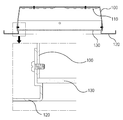
도 4 내지 도 6은 종래의 실내 조명등, 즉 다운라이트를 나타내는 사시도와 단면도이다. 4 to 6 is a perspective view and a cross-sectional view showing a conventional indoor lighting, that is, a downlight.
도 4 내지 도 6에 도시한 바와 같이, 상기 실내 조명등은 천장에 고정되는 조명등 케이스(100)와, 상기 조명등 케이스(100)의 내부에 설치되는 LED 어셈블리(110)와, 상기 조명등 케이스(100)의 하단부 둘레에 스크류 체결구조로 결합되는 틀 형태의 커버 홀더(120)와, 상기 조명등 케이스(100)의 하단부에 배치됨과 더불어 커버 홀더(120)와 조명등 케이스(100) 사이에 끼워져 지지되면서 내부의 LED 어셈블리(110)를 마감하는 투명 또는 반투명 소재의 조명등 커버(130)로 구성된다.4 to 6, the indoor lighting lamp is a
여기서, 미설명 부호 180은 조명등 케이스(100)를 천장에 설치할 때 사용하는 브라켓을 나타낸다. Here,
그러나, 종래의 실내 조명등은 다음과 같은 여러 단점이 있다. However, the conventional indoor lighting lamp has several disadvantages as follows.
첫째, 실내 조명등의 조립 시, 조명등 케이스(100)의 하단에 커버(130)의 위치를 잡은 다음, 커버 홀더(120)로 조명등 커버(130)를 덮은 상태에서 커버 홀더(120)와 조명등 케이스(100) 간의 다수 곳을 스크류로 체결해야 조립을 마칠 수 있으므로, 작업이 매우 불편할 뿐만 아니라 작업 시간도 많이 소요되는 등 작업성이 떨어지는 단점이 있다. First, when assembling the indoor lighting, the position of the
둘째, 실내 조명등의 제작 시, 금속 소재의 조명등 케이스(100)와 PP 소재의 커버 홀더(120)를 각각 프레스 성형과 압출 성형으로 제작해야 하는 등 부품수가 많고 각각의 금형을 필요로 하는 등 제작성 측면은 물론 제작 비용 측면에서 불리한 단점이 있다.Second, in the production of interior lighting lamps, the number of parts is large, such as the need to manufacture the
따라서, 본 발명은 이와 같은 점을 감안하여 안출한 것으로서, 조명등 케이스와 조명등 커버의 조립 시, 조명등 케이스의 개구부 둘레에 형성되어 있는 커버 고정턱에 조명등 커버의 가장자리를 눌러 끼워서 걸려지게 하는 새로운 조립 구조를 구현함으로써, 조립 작업을 신속하고 간편하게 할 수 있는 등 조립 작업성을 향상시킬 수 있는 실내 조명등을 제공하는데 그 목적이 있다. Therefore, the present invention has been devised in view of such a point, and when assembling the lighting case and the lighting cover, a new assembly structure is applied to the cover fixing jaw formed around the opening of the lighting case by pressing the edge of the lighting cover to be hung. The object of the present invention is to provide an indoor lighting lamp capable of improving assembly workability such as quick and easy assembly work.
또한, 본 발명의 다른 목적은 실내 조명등의 제작 시, 금속 프레스 성형을 통해 조명등 케이스의 기능과 커버 홀더의 기능을 겸비한 조명등 케이스를 제작하는 새로운 제작 방식을 구현함으로써, 부품수를 줄일 수 있고 금형의 수를 줄일 수 있으며 제작 비용을 절감할 수 있는 등 제작성 및 생산성, 그리고 경제성을 향상시킬 수 있는 실내 조명등을 제공하는데 있다.In addition, another object of the present invention is to implement a new manufacturing method of manufacturing a lighting case having both the function of the lighting case and the function of the cover holder through metal press molding during the production of the interior lighting, the number of parts can be reduced and The present invention is to provide an indoor lighting lamp that can improve production efficiency, productivity, and economy, such as reducing the number and reducing the production cost.
상기 목적을 달성하기 위하여 본 발명에서 제공하는 실내 조명등은 다음과 같은 특징이 있다.In order to achieve the above object, the indoor lighting provided by the present invention has the following characteristics.
상기 실내 조명등은 천장에 고정되는 조명등 케이스와, 상기 조명등 케이스의 내부에 설치되는 LED 어셈블리와, 상기 조명등 케이스의 하단부에 결합되어 내부의 LED 어셈블리를 마감하는 투명 또는 반투명 소재의 조명등 커버를 포함하는 구조로 이루어지며, 특히 상기 조명등 케이스의 개구부 둘레에는 하단부의 직경은 조명등 커버의 직경 대비 상대적으로 작은 직경으로 이루어짐과 더불어 상단부의 직경은 조명등 커버의 직경 대비 동일하거나 상대적으로 큰 직경으로 이루어진 테이퍼형 단면 형태의 커버 고정턱이 형성되어, 상기 조명등 케이스에 조명등 커버의 조립 시 조명등 커버의 가장자리 부분을 눌러 끼워서 커버 고정턱의 안쪽으로 걸려지게 하는 구조로 조립할 수 있도록 된 것이 특징이다. The interior lighting lamp includes a lighting case fixed to the ceiling, an LED assembly installed inside the lighting case, and a transparent or translucent material lighting cover coupled to a lower end of the lighting case to close the interior LED assembly. In particular, the diameter of the lower portion around the opening of the lamp case is made of a relatively small diameter compared to the diameter of the lamp cover, and the diameter of the upper portion is a tapered cross-sectional shape made of the same or relatively larger diameter than the diameter of the lamp cover. It is characterized in that the cover fixing jaw is formed so that it can be assembled into a structure such that when the lighting cover is assembled to the lighting case, the edge of the lighting cover is pressed to fit inside the cover fixing jaw.
여기서, 상기 조명등 케이스는 금속 소재로 이루어짐과 더불어 프레스 성형을 통해 커버 고정턱을 일체형으로 가지는 형태로 이루어질 수 있다. Here, the lighting case may be made of a metal material and may be formed in a form having an integral cover fixing jaw through press molding.
그리고, 상기 커버 고정턱의 하단부 직경과 상단부 직경은 2∼3㎜ 정도의 직경차를 갖도록 할 수 있다. In addition, the diameter of the lower end portion and the upper end portion of the cover fixing jaw may have a diameter difference of about 2 to 3 mm.
바람직한 실시예로서, 상기 조명등 케이스의 개구부와 조명등 커버는 원형, 사각형, 다각형 등 다양한 형태로 이루어질 수 있다.As a preferred embodiment, the opening of the lighting case and the lighting cover may be formed in various forms such as a circle, a square, and a polygon.
본 발명에서 제공하는 실내 조명등은 다음과 같은 효과가 있다.The indoor lighting provided by the present invention has the following effects.
첫째, 조명등 케이스의 개구부 둘레에 형성되어 있는 커버 고정턱에 조명등 커버의 가장자리를 눌러 끼워서 걸려지게 하는 구조로 조명등 커버를 조립함으로써, 작업자가 간단한 1회 누름 조작으로 조명등 커버를 조립할 수 있는 등 조립 작업을 신속하고 간편하게 할 수 있으며, 따라서 실내 조명등의 조립 작업성을 향상시킬 수 있는 효과가 있다. First, assembling the lamp cover by assembling the lamp cover with a structure that presses the edge of the lamp cover to the cover fixing jaw formed around the opening of the lamp case so that the operator can assemble the lamp cover with a simple one-press operation. It can be quickly and easily, and thus has the effect of improving the assembling workability of the indoor lighting.
둘째, 금속 프레스 성형을 통해 제작한 커버 홀더의 기능을 갖춘 새로운 구조의 조명등 케이스를 적용함으로써, 기존의 커버 홀더 부품을 삭제할 수 있는 등 실내 조명등의 부품수를 줄일 수 있고, 이와 관련하여 부품 제작에 필요한 금형의 수도 줄일 수 있는 등 전반적으로 제작성과 생산성을 향상시킬 수 있으며, 제작 비용을 대폭 절감할 수 있는 등 경제성 측면에서 유리한 효과가 있다. Second, by applying a new structured lighting case with the function of the cover holder produced through metal press molding, the number of parts of the interior lighting lamp can be reduced, such as deleting the existing cover holder parts, and in this regard, Overall, production efficiency and productivity can be improved by reducing the number of molds required, and it is advantageous in terms of economic efficiency, such as significantly reducing production costs.
셋째, 종전과 같이 커버 홀더와 조명등 케이스 간의 결합을 위한 다수 곳을 스크류 체결부위를 없앨 수 있으므로, 실내 조명등의 외관을 향상시킬 수 있는 효과가 있다. Third, as in the past, since the screw fastening portion can be eliminated in a plurality of places for coupling between the cover holder and the lighting case, there is an effect of improving the appearance of the interior lighting.
도 1과 도 2는 본 발명의 일 실시예에 따른 실내 조명등을 나타내는 사시도
도 3은 본 발명의 일 실시예에 따른 실내 조명등을 나타내는 단면도
도 4와 도 5는 종래의 실내 조명등을 나타내는 사시도
도 6은 종래의 실내 조명등을 나타내는 단면도1 and 2 are a perspective view showing an indoor lighting according to an embodiment of the present invention
Figure 3 is a cross-sectional view showing an indoor lighting according to an embodiment of the present invention
4 and 5 is a perspective view showing a conventional indoor lighting
Figure 6 is a cross-sectional view showing a conventional indoor lighting
이하, 첨부한 도면을 참조하여 본 발명을 상세히 설명하면 다음과 같다.Hereinafter, the present invention will be described in detail with reference to the accompanying drawings.
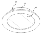
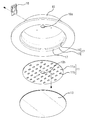
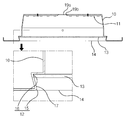
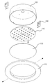
도 1과 도 2는 본 발명의 일 실시예에 따른 실내 조명등을 나타내는 사시도이고, 도 3은 본 발명의 일 실시예에 따른 실내 조명등을 나타내는 단면도이다. 1 and 2 are perspective views showing an indoor lighting lamp according to an embodiment of the present invention, and FIG. 3 is a cross-sectional view showing an indoor lighting lamp according to an embodiment of the present invention.
도 1 내지 도 3에 도시한 바와 같이, 상기 실내 조명등은 스크류 체결이나 공구 등을 사용하지 않고 단순 누름 조작에 의한 원터치 끼움방식으로 조명등 커버를 조립할 수 있고, 또 조명등 케이스에 직접 조명등 커버를 조립하는 구조를 채택하여 부품수를 줄일 수 있음은 물론 제작성을 향상시킬 수 있는 구조로 이루어진다. 1 to 3, the indoor lighting lamp can be assembled with a one-touch fitting method by a simple pressing operation without using a screw fastening or a tool, and also assembling the lighting cover directly into the lighting case. By adopting the structure, it is possible to reduce the number of parts, and it is made of a structure that can improve the production.
이를 위하여, 상기 실내 조명등은 실내의 천장에 고정 설치되는 조명등 케이스(10)를 포함한다.To this end, the indoor lamp includes a
상기 조명등 케이스(10)는 LED 어셈블리(11)를 수용하는 수단으로서, 아래쪽이 뚫려 있는 즉, 하단부에 원형의 개구부(14)를 가지는 금속 소재의 원형 하우징 형태로 이루어지게 된다. The
이러한 조명등 케이스(10)의 내부에는 LED 어셈블리(11)가 설치되며, 이렇게 설치되는 LED 어셈블리(11)는 조명등 케이스(10)의 하단부에 결합되는 조명등 커버(13)에 의해 마감될 수 있게 된다. The
그리고, 상기 조명등 케이스(10)의 상판 중앙에는 홀(19a)이 형성되어 있어서, 이때의 홀(19a)을 통해 인입되는 전선(미도시)이 LED 어셈블리(11)측에 배선될 수 있게 되고, 또 조명등 케이스(10)의 외주면 둘레에는 양쪽 2개의 브라켓(18)이 스크류 체결구조로 장착되어 있으며, 이에 따라 조명등 케이스(10)는 브라켓(18)을 통해 천장에 설치될 수 있게 된다. In addition, a
여기서, 상기 브라켓(18)을 이용하여 조명등 케이스(10)의 천장에 설치하는 방법은 당해 기술분야에서 통상적으로 알려져 있는 방법이라면 특별히 제한되지 않고 채택될 수 있다. Here, the method of installing on the ceiling of the
이와 같은 조명등 케이스(10)는 금속 소재로 이루어질 수 있으며, 프레스 성형을 통해 제작될 수 있게 된다. The
즉, 상기 조명등 케이스(10)는 금속 소재에 대한 프레스 성형 과정을 통해 후술하는 커버 고정턱(12)을 일체형으로 포함하는 형태로 제작될 수 있게 된다. That is, the
특히, 상기 조명등 케이스(10)는 간단한 누름조작을 통해 조명등 커버(13)를 원터치 방식으로 조립할 수 있도록 해주는 구조를 포함한다. In particular, the
이를 위하여, 상기 조명등 케이스(10)에 형성되어 있는 원형의 개구부(14)에는 하단부(15)의 직경이 원형을 이루는 조명등 커버(13)의 직경 대비 상대적으로 작은 직경으로 이루어짐과 더불어 상단부(16)의 직경이 조명등 커버(13)의 직경 대비 동일하거나 상대적으로 큰 직경으로 이루어진 구조의 커버 고정턱(12)이 형성된다. To this end, the
이렇게 형성되는 커버 고정턱(12)은 테이퍼형 단면 형태를 취하면서, 즉 상단부(16)에서 하단부(15)로 갈수록 점차 직경이 줄어드는 형상의 테이퍼면(17)을 가지는 단면 형태를 취하면서 개구부(14)의 전체 원주둘레를 따라 형성된다. The
이에 따라, 상기 조명등 케이스(10)의 하단부에 조명등 커버(13)를 조립할 때, 조명등 케이스(10)의 개구부(14)에 조명등 커버(13)를 동심원 상으로 배치한 다음, 조명등 커버(13)의 가장자리 부분을 어느 한쪽에서부터 살짝 눌러 끼우게 되면, 이때의 조명등 커버(13)는 소재 자체의 탄력적인 특성을 발휘하여 약간 휘어진 상태로 하단부(15)를 넘어선 후에 재차 복원되면서 그 가장자리 부분이 상단부(16) 내에 안착되므로서, 조명등 커버(13)는 자신의 직경보다 큰 직경을 가지는 하단부(15)에 걸려지면서 커버 고정턱(12) 내에 구속되는 구조로 조립될 수 있게 된다.Accordingly, when assembling the
이렇게 상기 조명등 커버(13)의 조립 시, 조명등 커버(13)를 조명등 케이스(10)의 개구부(14)에 대고 간단히 눌러주는 조작만으로 조명등 커버(13)를 쉽게 조립할 수 있으므로, 종전과 같이 커버 홀더를 매개로 한 스크류 체결방식 대비 조립 작업을 신속하고 간편할 수 있는 이점이 있다. In this way, when assembling the
여기서, 상기 커버 고정턱(13)의 하단부(15) 직경과 상단부(16) 직경은 조명등 커버(13)의 조립 시 조명등 커버(13)의 변형에 의한 파손, 조립 시에 가하는 힘의 균형 등을 고려하여 적절하게 설정하는 것이 바람직하다. Here, the diameter of the
즉, 상기 상단부(16)의 직경을 조명등 커버(13)의 직경과 동일 또는 유사한 직경으로 설정한 상태에서, 하단부(15)의 직경이 상단부(16)의 직경 대비 차이가 너무 크면 조명등 커버(13)를 무리하게 집어넣다가 조명등 커버(13)가 파손되거나 힘이 너무 많이 드는 단점이 있고, 또 하단부(15)의 직경이 상단부916)의 직경 대비 차이가 너무 없으면 조명등 커버(13)가 약간의 충격 등에도 쉽게 탈거될 수 있게 된다. That is, in a state in which the diameter of the
따라서, 상기 상단부(16)의 직경과 하단부(15)의 직경은 2∼3㎜ 정도의 직경차를 갖도록 하는 것이 바람직하다. Therefore, it is preferable that the diameter of the
일 예로, 5″다운라이트(스틸)의 경우 상단부(16)의 직경은 Ø108.0, 하단부(15)의 직경은 Ø105.6으로 설정할 수 있다. For example, in the case of a 5 ″ downlight (steel), the diameter of the
또한, 상기 실내 조명등은 조명등 케이스(10)의 내부에 설치되는 실내 조명을 위한 빛을 조사하는 LED 어셈블리(11)를 포함한다. In addition, the indoor lighting lamp includes an
상기 LED 어셈블리(11)는 원판 형태의 PCB(11a)와 이러한 PCB(11a) 상에 정렬 배치되는 다수 개의 LED(11b)로 구성되며, 조명등 케이스(10)의 상판 외부에 설치되어 있는 SMPS(미도시)측으로부터 전원을 공급받아 ON/OFF 작동될 수 있게 된다. The
이러한 LED 어셈블리(11)는 조명등 케이스(10)의 내부에 배치되어 케이스 상판의 저면에 밀착된 상태로 다수의 스크류 체결구조에 의해 고정되는 구조로 설치되며, PCB(11a)의 중앙에 형성되어 있는 홀(19b)을 통해 인입되는 전선(미도시), 즉 SMPS(미도시)측에서 연장되어 조명등 케이스(10)의 홀(19a)과 PCB(11a)의 홀(19b)을 통해 인입되는 전선(미도시)측과 배선되어 전원을 공급받을 수 있게 된다. The
또한, 상기 실내 조명등은 조명등 케이스(10)의 내부에 설치되는 LED 어셈블리(11)를 보호하는 수단으로 조명등 커버(13)를 포함한다. In addition, the indoor lamp includes a
상기 조명등 커버(13)는 PC, PS, PP 등과 같은 투명 또는 반투명 소재의 원판 형태로 이루어지게 되며, 조명등 케이스(10)의 하단부 둘레, 즉 개구부(14)의 가장자리를 따라 형성되어 있는 커버 고정턱(12)의 내측으로 끼워져 결합되는 구조로 설치될 수 있게 된다. The
예를 들면, 상기 조명등 커버(13)를 조명등 케이스(10)의 개구부(14)에 동심원 상으로 맞춘 상태에서 조명등 커버(13)를 간단히 눌러주는 조작에 의해 조명등 케이스(10)측에 조명등 커버(13)를 쉽게 조립할 수 있게 된다.For example, in the state in which the
이와 같이, 본 발명에서는 조명등 케이스와 조명등 커버의 조립 시, 조명등 케이스의 개구부 둘레에 형성되어 있는 커버 고정턱에 조명등 커버의 가장자리를 눌러 끼워서 걸려지게 하는 조립 구조와 조립 방식을 제공함으로써, 조명등 커버의 조립 작업을 신속하고 간편하게 할 수 있는 등 조립 작업성을 향상시킬 수 있고, 또 금속 프레스 성형을 통해 조명등 케이스의 기능과 커버 홀더의 기능을 겸비한 조명등 케이스를 제작하는 방식을 제공함으로써, 기존의 커버 홀더 등과 같은 부품을 삭제할 수 있는 등 부품수를 줄일 수 있는 동시에 금형의 수를 줄일 수 있으며, 따라서 제작 비용을 절감할 수 있고 제작성 및 생산성을 향상시킬 수 있다. As described above, according to the present invention, when assembling the lighting case and the lighting cover, by providing an assembly structure and an assembly method of pressing the edge of the lighting cover on the cover fixing jaw formed around the opening of the lighting case, thereby providing an assembly structure and an assembly method. Existing cover holder by providing a method of manufacturing a lighting case that combines the function of a lighting case and the function of a cover holder through metal press molding, which can improve assembly workability, such as quick and easy assembly work. It is possible to reduce the number of parts, such as the number of parts that can be deleted, and at the same time reduce the number of molds, thus reducing manufacturing costs and improving productivity and productivity.
10 : 조명등 케이스
11 : LED 어셈블리
11a : PCB
11b : LED
12 : 커버 고정턱
13 : 조명등 커버
14 : 개구부
15 : 하단부
16 : 상단부
17 : 테이퍼면
18 : 브라켓
19a,19b : 홀10: lighting case
11: LED assembly
11a: PCB
11b: LED
12: cover fixing jaw
13: lighting cover
14: opening
15: lower part
16: upper part
17: tapered cotton
18: bracket
19a, 19b: Hall
Claims (4)
상기 조명등 케이스(10)의 개구부(14) 둘레에는 하단부(15)의 직경은 조명등 커버(13)의 직경 대비 상대적으로 작은 직경으로 이루어짐과 더불어 상단부(16)의 직경은 조명등 커버(13)의 직경 대비 동일하거나 상대적으로 큰 직경으로 이루어진 테이퍼형 단면 형태의 커버 고정턱(12)이 형성되어, 상기 조명등 케이스(10)에 조명등 커버(13)의 조립 시 조명등 커버(13)의 가장자리 부분을 눌러 끼워서 커버 고정턱(12)의 안쪽으로 걸려지게 하는 구조로 조립할 수 있도록 된 것을 특징으로 하는 실내 조명등.
A lighting case 10 fixed to the ceiling, an LED assembly 11 installed inside the lighting case 10, and coupled to a lower end of the lighting case 10 to close the interior LED assembly 11 It includes a transparent or translucent material lighting cover 13,
Around the opening 14 of the lighting case 10, the diameter of the lower end 15 is made of a relatively small diameter compared to the diameter of the lighting cover 13, and the diameter of the upper part 16 is the diameter of the lighting cover 13 A cover fixing jaw 12 having a tapered cross-section shape having the same or relatively large diameter is formed, and when assembling the lighting cover 13 in the lighting case 10, pressing the edge portion of the lighting cover 13 to fit Indoor lighting, characterized in that it can be assembled into a structure to be hung inside the cover fixing jaw (12).
상기 조명등 케이스(10)는 금속 소재로 이루어짐과 더불어 프레스 성형을 통해 커버 고정턱(12)을 일체형으로 가지는 형태로 이루어지는 것을 특징으로 하는 실내 조명등.
The method according to claim 1,
The lighting case 10 is made of a metal material and the interior lighting lamp characterized in that it is made of a form having a cover fixing jaw 12 integrally through press molding.
상기 커버 고정턱(13)의 하단부(15) 직경과 상단부(16) 직경은 2∼3㎜ 정도의 직경차를 갖는 것을 특징으로 하는 실내 조명등.
The method according to claim 1 or claim 2,
Indoor lighting lamp, characterized in that the diameter of the lower end portion 15 and the upper end portion 16 of the cover fixing jaw 13 has a diameter of about 2 to 3 mm.
상기 조명등 케이스(10)의 개구부(14)와 조명등 커버(13)는 원형으로 이루어지는 것을 특징으로 하는 실내 조명등.The method according to claim 1 or claim 2,
The interior of the lighting case (10) and the lighting lamp cover (13) is characterized in that the indoor lighting is made of a circle.
Priority Applications (1)
| Application Number | Priority Date | Filing Date | Title |
|---|---|---|---|
| KR1020180109007A KR20200030300A (en) | 2018-09-12 | 2018-09-12 | Downlight |
Applications Claiming Priority (1)
| Application Number | Priority Date | Filing Date | Title |
|---|---|---|---|
| KR1020180109007A KR20200030300A (en) | 2018-09-12 | 2018-09-12 | Downlight |
Publications (1)
| Publication Number | Publication Date |
|---|---|
| KR20200030300A true KR20200030300A (en) | 2020-03-20 |
Family
ID=69958173
Family Applications (1)
| Application Number | Title | Priority Date | Filing Date |
|---|---|---|---|
| KR1020180109007A KR20200030300A (en) | 2018-09-12 | 2018-09-12 | Downlight |
Country Status (1)
| Country | Link |
|---|---|
| KR (1) | KR20200030300A (en) |
Cited By (5)
| Publication number | Priority date | Publication date | Assignee | Title |
|---|---|---|---|---|
| KR20220067598A (en) | 2020-11-16 | 2022-05-25 | 이기용 | Ceiling down light |
| KR20220002179U (en) | 2021-03-04 | 2022-09-14 | 양영옥 | Down light illuminator |
| KR20220144461A (en) | 2021-04-19 | 2022-10-27 | 이기용 | Ceiling light |
| KR20240127557A (en) | 2023-02-16 | 2024-08-23 | 경운대학교 산학협력단 | Flexible multi-color lighting for aircraft that can be attached and used in various locations |
| KR20240128181A (en) | 2023-02-16 | 2024-08-26 | 이기용 | Ceiling light |
Citations (5)
| Publication number | Priority date | Publication date | Assignee | Title |
|---|---|---|---|---|
| KR20130084936A (en) | 2012-01-18 | 2013-07-26 | 주식회사 아모럭스 | Light emitting diode down-light |
| KR20170041347A (en) | 2015-10-07 | 2017-04-17 | 서옥림 | high efficient edge type slim LED downlight |
| KR20170086326A (en) | 2016-01-18 | 2017-07-26 | 주식회사 나스필코리아 | Lightweight down Light device with insulation function |
| KR20180001401A (en) | 2016-06-27 | 2018-01-04 | 유동걸 | Down-light lighting device haivng air cleaner |
| KR20180010851A (en) | 2016-07-22 | 2018-01-31 | 주식회사 아모센스 | down light |
-
2018
- 2018-09-12 KR KR1020180109007A patent/KR20200030300A/en not_active Application Discontinuation
Patent Citations (5)
| Publication number | Priority date | Publication date | Assignee | Title |
|---|---|---|---|---|
| KR20130084936A (en) | 2012-01-18 | 2013-07-26 | 주식회사 아모럭스 | Light emitting diode down-light |
| KR20170041347A (en) | 2015-10-07 | 2017-04-17 | 서옥림 | high efficient edge type slim LED downlight |
| KR20170086326A (en) | 2016-01-18 | 2017-07-26 | 주식회사 나스필코리아 | Lightweight down Light device with insulation function |
| KR20180001401A (en) | 2016-06-27 | 2018-01-04 | 유동걸 | Down-light lighting device haivng air cleaner |
| KR20180010851A (en) | 2016-07-22 | 2018-01-31 | 주식회사 아모센스 | down light |
Cited By (5)
| Publication number | Priority date | Publication date | Assignee | Title |
|---|---|---|---|---|
| KR20220067598A (en) | 2020-11-16 | 2022-05-25 | 이기용 | Ceiling down light |
| KR20220002179U (en) | 2021-03-04 | 2022-09-14 | 양영옥 | Down light illuminator |
| KR20220144461A (en) | 2021-04-19 | 2022-10-27 | 이기용 | Ceiling light |
| KR20240127557A (en) | 2023-02-16 | 2024-08-23 | 경운대학교 산학협력단 | Flexible multi-color lighting for aircraft that can be attached and used in various locations |
| KR20240128181A (en) | 2023-02-16 | 2024-08-26 | 이기용 | Ceiling light |
Similar Documents
| Publication | Publication Date | Title |
|---|---|---|
| KR20200030300A (en) | Downlight | |
| USD869082S1 (en) | Lighting fixture | |
| KR101089055B1 (en) | Suspending lamp for ceiling improved in assembly structure | |
| JP2010010045A (en) | Holding member and embedded apparatus | |
| KR101605402B1 (en) | Ceiling mounted type lamp frame | |
| US20080285291A1 (en) | Recessed light retrofit kit | |
| ATE518096T1 (en) | RECESSED LIGHT | |
| KR20160002823U (en) | Lamp cover | |
| US10502397B1 (en) | Replaceable baffles for light fixtures | |
| KR200413753Y1 (en) | Ceiling light | |
| KR101904104B1 (en) | LED Ceiling light | |
| KR101103258B1 (en) | A foundation equipment for ceiling down light | |
| JP4333432B2 (en) | Downlight | |
| KR200424325Y1 (en) | Ceiling insert type light | |
| KR101562231B1 (en) | Ceiling light | |
| KR102434885B1 (en) | Ceiling Recessed Mounting Type Protrusion Ceiling Light | |
| KR101667610B1 (en) | LED ceiling lights | |
| KR101553523B1 (en) | Interior ceiling lights | |
| KR101311961B1 (en) | Lighting apparatus for multiple fixing-type | |
| KR101468326B1 (en) | Led lamp | |
| KR100715258B1 (en) | A ceiling light | |
| KR20220002179U (en) | Down light illuminator | |
| CN212430773U (en) | Universal lamp mounting part | |
| KR102673245B1 (en) | Device to mounting cover for lighting | |
| KR101778000B1 (en) | Decorative lighting in the form of a cocktail glass |
Legal Events
| Date | Code | Title | Description |
|---|---|---|---|
| E601 | Decision to refuse application |