KR20200030103A - printer - Google Patents
printer Download PDFInfo
- Publication number
- KR20200030103A KR20200030103A KR1020207004592A KR20207004592A KR20200030103A KR 20200030103 A KR20200030103 A KR 20200030103A KR 1020207004592 A KR1020207004592 A KR 1020207004592A KR 20207004592 A KR20207004592 A KR 20207004592A KR 20200030103 A KR20200030103 A KR 20200030103A
- Authority
- KR
- South Korea
- Prior art keywords
- metric
- layer
- injection profile
- build
- build material
- Prior art date
Links
Images


Classifications
-
- B—PERFORMING OPERATIONS; TRANSPORTING
- B29—WORKING OF PLASTICS; WORKING OF SUBSTANCES IN A PLASTIC STATE IN GENERAL
- B29C—SHAPING OR JOINING OF PLASTICS; SHAPING OF MATERIAL IN A PLASTIC STATE, NOT OTHERWISE PROVIDED FOR; AFTER-TREATMENT OF THE SHAPED PRODUCTS, e.g. REPAIRING
- B29C64/00—Additive manufacturing, i.e. manufacturing of three-dimensional [3D] objects by additive deposition, additive agglomeration or additive layering, e.g. by 3D printing, stereolithography or selective laser sintering
- B29C64/30—Auxiliary operations or equipment
- B29C64/307—Handling of material to be used in additive manufacturing
- B29C64/343—Metering
-
- B—PERFORMING OPERATIONS; TRANSPORTING
- B33—ADDITIVE MANUFACTURING TECHNOLOGY
- B33Y—ADDITIVE MANUFACTURING, i.e. MANUFACTURING OF THREE-DIMENSIONAL [3-D] OBJECTS BY ADDITIVE DEPOSITION, ADDITIVE AGGLOMERATION OR ADDITIVE LAYERING, e.g. BY 3-D PRINTING, STEREOLITHOGRAPHY OR SELECTIVE LASER SINTERING
- B33Y50/00—Data acquisition or data processing for additive manufacturing
- B33Y50/02—Data acquisition or data processing for additive manufacturing for controlling or regulating additive manufacturing processes
-
- B—PERFORMING OPERATIONS; TRANSPORTING
- B22—CASTING; POWDER METALLURGY
- B22F—WORKING METALLIC POWDER; MANUFACTURE OF ARTICLES FROM METALLIC POWDER; MAKING METALLIC POWDER; APPARATUS OR DEVICES SPECIALLY ADAPTED FOR METALLIC POWDER
- B22F10/00—Additive manufacturing of workpieces or articles from metallic powder
- B22F10/30—Process control
- B22F10/31—Calibration of process steps or apparatus settings, e.g. before or during manufacturing
-
- B—PERFORMING OPERATIONS; TRANSPORTING
- B29—WORKING OF PLASTICS; WORKING OF SUBSTANCES IN A PLASTIC STATE IN GENERAL
- B29C—SHAPING OR JOINING OF PLASTICS; SHAPING OF MATERIAL IN A PLASTIC STATE, NOT OTHERWISE PROVIDED FOR; AFTER-TREATMENT OF THE SHAPED PRODUCTS, e.g. REPAIRING
- B29C64/00—Additive manufacturing, i.e. manufacturing of three-dimensional [3D] objects by additive deposition, additive agglomeration or additive layering, e.g. by 3D printing, stereolithography or selective laser sintering
- B29C64/20—Apparatus for additive manufacturing; Details thereof or accessories therefor
- B29C64/205—Means for applying layers
- B29C64/209—Heads; Nozzles
-
- B—PERFORMING OPERATIONS; TRANSPORTING
- B29—WORKING OF PLASTICS; WORKING OF SUBSTANCES IN A PLASTIC STATE IN GENERAL
- B29C—SHAPING OR JOINING OF PLASTICS; SHAPING OF MATERIAL IN A PLASTIC STATE, NOT OTHERWISE PROVIDED FOR; AFTER-TREATMENT OF THE SHAPED PRODUCTS, e.g. REPAIRING
- B29C64/00—Additive manufacturing, i.e. manufacturing of three-dimensional [3D] objects by additive deposition, additive agglomeration or additive layering, e.g. by 3D printing, stereolithography or selective laser sintering
- B29C64/30—Auxiliary operations or equipment
- B29C64/386—Data acquisition or data processing for additive manufacturing
- B29C64/393—Data acquisition or data processing for additive manufacturing for controlling or regulating additive manufacturing processes
-
- G—PHYSICS
- G05—CONTROLLING; REGULATING
- G05B—CONTROL OR REGULATING SYSTEMS IN GENERAL; FUNCTIONAL ELEMENTS OF SUCH SYSTEMS; MONITORING OR TESTING ARRANGEMENTS FOR SUCH SYSTEMS OR ELEMENTS
- G05B19/00—Programme-control systems
- G05B19/02—Programme-control systems electric
- G05B19/418—Total factory control, i.e. centrally controlling a plurality of machines, e.g. direct or distributed numerical control [DNC], flexible manufacturing systems [FMS], integrated manufacturing systems [IMS], computer integrated manufacturing [CIM]
- G05B19/41875—Total factory control, i.e. centrally controlling a plurality of machines, e.g. direct or distributed numerical control [DNC], flexible manufacturing systems [FMS], integrated manufacturing systems [IMS], computer integrated manufacturing [CIM] characterised by quality surveillance of production
-
- B—PERFORMING OPERATIONS; TRANSPORTING
- B22—CASTING; POWDER METALLURGY
- B22F—WORKING METALLIC POWDER; MANUFACTURE OF ARTICLES FROM METALLIC POWDER; MAKING METALLIC POWDER; APPARATUS OR DEVICES SPECIALLY ADAPTED FOR METALLIC POWDER
- B22F10/00—Additive manufacturing of workpieces or articles from metallic powder
- B22F10/20—Direct sintering or melting
- B22F10/28—Powder bed fusion, e.g. selective laser melting [SLM] or electron beam melting [EBM]
-
- B—PERFORMING OPERATIONS; TRANSPORTING
- B22—CASTING; POWDER METALLURGY
- B22F—WORKING METALLIC POWDER; MANUFACTURE OF ARTICLES FROM METALLIC POWDER; MAKING METALLIC POWDER; APPARATUS OR DEVICES SPECIALLY ADAPTED FOR METALLIC POWDER
- B22F12/00—Apparatus or devices specially adapted for additive manufacturing; Auxiliary means for additive manufacturing; Combinations of additive manufacturing apparatus or devices with other processing apparatus or devices
- B22F12/90—Means for process control, e.g. cameras or sensors
-
- B—PERFORMING OPERATIONS; TRANSPORTING
- B22—CASTING; POWDER METALLURGY
- B22F—WORKING METALLIC POWDER; MANUFACTURE OF ARTICLES FROM METALLIC POWDER; MAKING METALLIC POWDER; APPARATUS OR DEVICES SPECIALLY ADAPTED FOR METALLIC POWDER
- B22F2999/00—Aspects linked to processes or compositions used in powder metallurgy
-
- B—PERFORMING OPERATIONS; TRANSPORTING
- B33—ADDITIVE MANUFACTURING TECHNOLOGY
- B33Y—ADDITIVE MANUFACTURING, i.e. MANUFACTURING OF THREE-DIMENSIONAL [3-D] OBJECTS BY ADDITIVE DEPOSITION, ADDITIVE AGGLOMERATION OR ADDITIVE LAYERING, e.g. BY 3-D PRINTING, STEREOLITHOGRAPHY OR SELECTIVE LASER SINTERING
- B33Y30/00—Apparatus for additive manufacturing; Details thereof or accessories therefor
-
- G—PHYSICS
- G05—CONTROLLING; REGULATING
- G05B—CONTROL OR REGULATING SYSTEMS IN GENERAL; FUNCTIONAL ELEMENTS OF SUCH SYSTEMS; MONITORING OR TESTING ARRANGEMENTS FOR SUCH SYSTEMS OR ELEMENTS
- G05B2219/00—Program-control systems
- G05B2219/30—Nc systems
- G05B2219/49—Nc machine tool, till multiple
- G05B2219/49013—Deposit layers, cured by scanning laser, stereo lithography SLA, prototyping
-
- G—PHYSICS
- G05—CONTROLLING; REGULATING
- G05B—CONTROL OR REGULATING SYSTEMS IN GENERAL; FUNCTIONAL ELEMENTS OF SUCH SYSTEMS; MONITORING OR TESTING ARRANGEMENTS FOR SUCH SYSTEMS OR ELEMENTS
- G05B2219/00—Program-control systems
- G05B2219/30—Nc systems
- G05B2219/49—Nc machine tool, till multiple
- G05B2219/49036—Use quality measures, build time, strength of material, surface approximation
-
- Y—GENERAL TAGGING OF NEW TECHNOLOGICAL DEVELOPMENTS; GENERAL TAGGING OF CROSS-SECTIONAL TECHNOLOGIES SPANNING OVER SEVERAL SECTIONS OF THE IPC; TECHNICAL SUBJECTS COVERED BY FORMER USPC CROSS-REFERENCE ART COLLECTIONS [XRACs] AND DIGESTS
- Y02—TECHNOLOGIES OR APPLICATIONS FOR MITIGATION OR ADAPTATION AGAINST CLIMATE CHANGE
- Y02P—CLIMATE CHANGE MITIGATION TECHNOLOGIES IN THE PRODUCTION OR PROCESSING OF GOODS
- Y02P10/00—Technologies related to metal processing
- Y02P10/25—Process efficiency
-
- Y—GENERAL TAGGING OF NEW TECHNOLOGICAL DEVELOPMENTS; GENERAL TAGGING OF CROSS-SECTIONAL TECHNOLOGIES SPANNING OVER SEVERAL SECTIONS OF THE IPC; TECHNICAL SUBJECTS COVERED BY FORMER USPC CROSS-REFERENCE ART COLLECTIONS [XRACs] AND DIGESTS
- Y02—TECHNOLOGIES OR APPLICATIONS FOR MITIGATION OR ADAPTATION AGAINST CLIMATE CHANGE
- Y02P—CLIMATE CHANGE MITIGATION TECHNOLOGIES IN THE PRODUCTION OR PROCESSING OF GOODS
- Y02P90/00—Enabling technologies with a potential contribution to greenhouse gas [GHG] emissions mitigation
- Y02P90/02—Total factory control, e.g. smart factories, flexible manufacturing systems [FMS] or integrated manufacturing systems [IMS]
Abstract
프린터가 개시된다. 예시적인 프린터는 작업 영역 상의 층의 메트릭에 액세스하고, 메트릭에 기초하여 복수의 주입 프로파일 중에서 층을 융해하기 위한 주입 프로파일을 선택하는 빌드 제어기를 포함한다.The printer is started. The exemplary printer includes a build controller that accesses a metric of the layer on the work area and selects an injection profile to melt the layer from among multiple injection profiles based on the metric.
Description
적층 제조 시스템은 3차원 물체를 생성하는 데 사용될 수 있다. 일부 예에서, 3차원 물체는 빌드 재료를 사용하여 층으로 생성된다.Additive manufacturing systems can be used to create three-dimensional objects. In some examples, three-dimensional objects are created in layers using build materials.
도 1은 본 발명의 교시에 따른 예시적인 프린터의 개략도이다.
도 2는 도 1의 예시적인 빌드 제어기의 개략도이다.
도 3은 도 2의 예시적인 빌드 제어기를 구현하기 위해 실행될 수 있는 머신 판독가능 명령어를 나타내는 흐름도이다.
도 4는 도 2의 예시적인 빌드 제어기를 구현하기 위해 실행될 수 있는 머신 판독가능 명령어를 나타내는 흐름도이다.
도 5는 도 2의 예시적인 빌드 제어기를 구현하기 위해 도 3 및 도 4의 명령어를 실행하는 프로세서 플랫폼이다.
도면은 스케일링되어서는 안 된다. 가능하다면, 동일하거나 유사한 부분을 지칭하기 위해 동일한 참조 번호가 도면(들) 및 첨부된 서면 설명 도처에서 사용될 것이다. 도면은 프린터 및 관련 빌드 제어기의 예를 도시하지만, 본 명세서에 개시된 예를 구현하는 데 다른 예가 이용될 수 있다.1 is a schematic diagram of an exemplary printer in accordance with the teachings of the present invention.
2 is a schematic diagram of the exemplary build controller of FIG. 1.
3 is a flow diagram illustrating machine readable instructions that can be executed to implement the example build controller of FIG. 2.
4 is a flow diagram illustrating machine readable instructions that can be executed to implement the example build controller of FIG. 2.
5 is a processor platform that executes the instructions of FIGS. 3 and 4 to implement the example build controller of FIG. 2.
The drawings should not be scaled. Where possible, the same reference numbers will be used throughout the drawing (s) and accompanying written description to refer to the same or similar parts. Although the drawings show examples of printers and related build controllers, other examples may be used to implement the examples disclosed herein.
본 명세서에 개시된 예는 적층 제조 공정 동안 현장에서 빌드 메트릭을 결정하고, 결정된 빌드 메트릭과 참조 빌드 메트릭 사이의 차이를 식별하며, 식별된 차이를 해결하기 위해 적층 제조 공정의 빌드 특성을 실시간으로 변경하는 것에 관한 것이다. 따라서, 본 발명의 교시에 따라 생성된 물체는 후속 및/또는 값비싼 품질 분석이 발생하지 않고도 제조 공정 동안 품질 임계값을 만족시키도록 결정될 수 있다. 또한, 본 명세서에 개시된 예는 실질적으로 실시간으로 수신된 피드백에 기초하여 빌드 공정이 동적으로 업데이트되게 하여 생성된 물체가 원하는 결과를 만족시킬 수 있게 한다. 본 명세서에 설명된 바와 같이, "실질적으로 실시간"은 전송 및/또는 처리 지연을 설명한다. 이전 층, 이전 빌드 및/또는 다른 데이터에 기초하여 적층 제조 공정을 동적으로 업데이트함으로써, 본 명세서에 개시된 예는 품질 임계값을 만족시키지 않는 생성된 물체, 층 등의 수를 감소시킨다.The examples disclosed herein determine build metrics in situ during the additive manufacturing process, identify differences between the determined build metrics and reference build metrics, and change the build properties of the additive manufacturing process in real time to address the identified differences. It's about things. Thus, an object produced in accordance with the teachings of the present invention can be determined to satisfy a quality threshold during the manufacturing process without subsequent and / or costly quality analysis occurring. In addition, the examples disclosed herein allow the build process to be dynamically updated based on feedback received in real time, so that the resulting object can satisfy the desired results. As described herein, "substantially real-time" describes transmission and / or processing delays. By dynamically updating the additive manufacturing process based on previous layers, previous builds and / or other data, the examples disclosed herein reduce the number of objects, layers, etc. created that do not satisfy the quality threshold.
일부 예에서, 적층 제조 공정의 빌드 특성을 변경하는 것은 토포그래피 변화를 감소시키기 위해 작업 영역에 빌드 재료를 재분포하고, 작업 영역의 z 위치를 변경하여 작업 영역 상의 빌드 재료의 경사도 및/또는 두께를 변경하는 것 및/또는 빌드 재료 디스펜서의 z 위치를 변경하여 작업 영역 상의 빌드 재료의 경사도 및/또는 두께를 변경하는 것을 포함한다. 빌드 재료 디스펜서는 블레이드, 와이퍼, 롤러, 브러시 등을 포함할 수 있다.In some examples, changing the build properties of the additive manufacturing process redistributes the build material to the work area to reduce topographic changes, and changes the z position of the work area to change the slope and / or thickness of the build material on the work area. And / or changing the z position of the build material dispenser to change the slope and / or thickness of the build material on the work area. Build material dispensers can include blades, wipers, rollers, brushes, and the like.
부가적으로 또는 대안적으로, 일부 예에서, 적층 제조 공정의 빌드 특성을 변경하는 것은 빌드 재료 층들을 융해하기 위해 주입 프로파일을 결정 및/또는 선택하는 것을 포함한다. 다시 말해, 일부 층은 제1 주입 프로파일을 사용하여 융해될 수 있고 일부 층은 제2 주입 프로파일을 사용하여 융해될 수 있다. 주입 프로파일은 작업 영역(예를 들어, 베드) 상의 빌드 재료 층에 제공된 작용제(예를 들어, 융해제 또는 에너지 흡수제)의 주입량 및/또는 작업 영역 상의 빌드 재료 층에 제공된 에너지의 양 및/또는 유형을 포함할 수 있다. 일부 예에서, 작용제 및/또는 에너지는 층에 상이하게 분포 및/또는 도포될 수 있다. 예를 들어, 층의 한 구역은 제1 주입량의 작용제 및/또는 제1 양의 융해 에너지를 수용할 수 있고, 층의 제2 구역은 제2 주입량의 작용제 및/또는 제2 양의 융해 에너지를 수용할 수 있다. 앞에서 설명한 예는 융해제 및 융해 에너지를 사용하여 층을 융해하는 것을 언급하지만, 다른 예에서, 예를 들어, 작용제를 도포하지 않고도 층을 융해하는 데 레이저 및/또는 다른 에너지원이 사용된다. 물론, 어떠한 현재 또는 미래의 적층 제조 공정도 본 발명의 교시를 이용할 수 있다.Additionally or alternatively, in some examples, changing the build properties of the additive manufacturing process includes determining and / or selecting an injection profile to melt the build material layers. In other words, some layers can be melted using the first injection profile and some layers can be melted using the second injection profile. The injection profile is the amount and / or type of energy supplied to the build material layer on the work area and / or the amount of injection of the agent (eg, a disintegrant or energy absorber) provided to the build material layer on the work area (eg bed) It may include. In some examples, the agent and / or energy can be distributed and / or applied differently to the layer. For example, one section of the layer may receive a first injection amount of agonist and / or a first amount of melting energy, and a second section of the layer may receive a second injection amount of agonist and / or a second amount of melting energy. Can accommodate Although the examples described above refer to melting layers using a melting agent and melting energy, in other examples, lasers and / or other energy sources are used to melt the layers, for example, without applying an agent. Of course, any present or future additive manufacturing process can utilize the teachings of the present invention.
생성된 물체가 3D 공간에서 재생성될 수 있도록 하기 위해, 일부 예에서, 메트릭, 선택된 주입 프로파일 및/또는 다른 관련 데이터를 포함하는 모델이 생성된다. 모델 및/또는 관련 메트릭은 생성된 물체의 층의 토포그래피 및/또는 층(들)을 나타내고/내거나 관련된 좌표(X, Y, Z 좌표)(예를 들어, 층의 로컬 세부사항)에 대한 세부사항을 포함할 수 있다. 추가적으로 또는 대안적으로, 모델 및/또는 관련 메트릭(예를 들어, 좌표, 3D 좌표의 어레이)은 z 축에서의 축적된 특징부 이동의 맵, 키홀의 맵 및/또는 빌드 평면(들) 내의 빌드 재료 두께 맵을 생성하는 데 사용될 수 있다. 일부 예에서, 키홀은 적층 제조 공정 동안 형성되며, (예를 들어, 표면에서) 넓고 상승된 헤드 및 (예를 들어, 부품 내) 베이스에서의 포트를 포함하는 "키홀" 형상을 갖는다. 일부 예에서, z 축에서의 빌드 특징부 이동은 응력 축적을 나타낼 수 있다. 일부 예에서, 키홀과 연관된 특성을 검색함으로써 키홀이 층 및/또는 물체에서 식별된 후 키홀의 맵을 생성하는 데 상이한 층들을 표현 및/또는 기술하는 좌표가 사용될 수 있다.In order to allow the resulting object to be regenerated in 3D space, in some examples, a model is generated that includes metrics, selected injection profiles and / or other related data. The model and / or related metrics represent the topography and / or layer (s) of the layer of the generated object and / or details about the associated coordinates (X, Y, Z coordinates) (eg, local details of the layer). May include: Additionally or alternatively, the model and / or related metrics (e.g., coordinates, arrays of 3D coordinates) can be built in a map of accumulated feature movements in the z axis, a map of keyholes, and / or builds in the build plane (s). It can be used to generate material thickness maps. In some examples, the keyholes are formed during the additive manufacturing process, and have a “keyhole” shape that includes a wide, raised head (eg, at the surface) and ports at the base (eg, in the part). In some examples, movement of build features in the z-axis may indicate stress buildup. In some examples, coordinates that represent and / or describe different layers can be used to generate a map of the keyhole after the keyhole is identified in the layer and / or object by searching for properties associated with the keyhole.
일부 예에서, 빌드 재료 두께 맵은 작업 영역 상에 형성되는 빌드 재료의 두께의 경향(들)을 식별하는 데 사용될 수 있다. 예를 들어, 빌드 재료 두께 맵은 작업 영역의 제1 영역에 더 많은 양의 빌드 재료가 증착되고 작업 영역의 제2 영역에 더 적은 양의 빌드 재료가 증착되는 경향(예를 들어, 의도하지 않은 경향)을 식별하는 데 사용될 수 있다. 추가적으로 또는 대안적으로, 빌드 재료 두께 맵은 경향이 임계값을 만족시키고/시키거나 초과할 때 구성요소(예를 들어, 빌드 재료 디스펜서의 블레이드)가 유지보수를 받아야 함을 나타내는 경향을 식별하는 데 사용될 수 있다. 빌드 재료 두께 맵은 상이한 방식으로 생성될 수 있지만, 일부 예에서, 빌드 재료 두께 맵은 층들에 대한 z 높이 데이터를 획득하고 비교함으로써 생성된다. 비교는 최상층의 z 높이 데이터와 이전 층(들)의 z 높이 데이터를 비교하는 것을 포함할 수 있다.In some examples, a build material thickness map can be used to identify trend (s) of the build material thickness formed on the work area. For example, the build material thickness map tends to result in a greater amount of build material being deposited in the first area of the work area and less amount of build material being deposited in the second area of the work area (e.g., unintentional) Trend). Additionally or alternatively, the build material thickness map is used to identify trends that indicate that a component (eg, a blade of a build material dispenser) needs to be maintained when the trend meets and / or exceeds a threshold. Can be used. The build material thickness map can be generated in different ways, but in some examples, the build material thickness map is generated by obtaining and comparing z height data for the layers. The comparison may include comparing z height data of the top layer and z height data of the previous layer (s).
일부 예에서, 빌드 재료가 층들에 대해 확산 및/또는 분포되는 방법을 나타내는 데 상이한 층들을 기술하는 좌표가 사용될 수 있다. 예를 들어, 층의 두께, 층의 토포그래피 등을 포함하는 빌드 재료 층의 지식을 사용하여, 일부 예에서, 층이 융해되기 전에 층의 결정된 메트릭에 맞춰지는 주입 프로파일 및/또는 맵이 선택되거나 생성될 수 있다. 부가적으로 또는 대안적으로, 빌드 재료 층 또는 층들 및/또는 그와 관련된 특성에 대한 지식을 이용하여, 층이 형성되기 전에 층의 결정된 메트릭에 맞춰지는 에너지 프로파일 및/또는 맵이 선택되고/되거나 생성될 수 있다. 일부 예에서, 층(들) 및/또는 물체 자체의 모델 및/또는 맵이 분석을 위해 및/또는 층(들) 및/또는 물체를 표현하기 위해 생성될 수 있다.In some examples, coordinates describing different layers can be used to indicate how the build material is diffused and / or distributed over the layers. For example, using the knowledge of a layer of build material, including the thickness of the layer, the topography of the layer, etc., in some examples, an injection profile and / or map that matches the determined metric of the layer before the layer melts is selected or Can be created. Additionally or alternatively, using a knowledge of the build material layer or layers and / or properties associated therewith, an energy profile and / or map that matches the determined metric of the layer before the layer is formed is selected and / or Can be created. In some examples, a model and / or map of the layer (s) and / or object itself can be generated for analysis and / or to represent the layer (s) and / or object.
특정 주입 프로파일을 사용하여 생성된 물체가 예상 결과를 만족시키고/시키거나 적층 제조 공정이 발생하기 전, 도중 및/또는 후에 주입 프로파일을 동적으로 교정 및/또는 업데이트할 수 있도록 하기 위해, 일부 예에서, 주입 프로파일은 업데이트 가능하다. 예를 들어, 선택된 주입 프로파일과 관련하여 생성된 물체가 예상 빌드 특성을 만족시키지 않으면, 주입 프로파일은 후속 적층 제조 공정 동안 인가된 융해제 및/또는 융해 에너지를 변경함으로써 업데이트될 수 있다. 일부 예에서, 후속 적층 제조 공정은 분포된 다음 빌드 재료 층에서 수행되는 공정(들)을 포함한다. 일부 예에서, 후속 적층 제조 공정(들)은 생성되는 현재 물체에 수행된 공정(들)을 포함한다. 일부 예에서, 후속 적층 제조 공정은 생성된 후속 물체에 수행되는 공정(들)을 포함한다. 따라서, 적층 제조 공정 동안 획득된 데이터 및/또는 지식에 기초하여, 본 명세서에 개시된 예는 주입 프로파일을 업데이트하여 생성된 후속 층 및/또는 물체에서 원하는 결과가 달성될 수 있게 한다.In order to allow objects created using a particular injection profile to meet expected results and / or to dynamically correct and / or update the injection profile before, during and / or after the additive manufacturing process occurs, in some examples , The injection profile is updatable. For example, if an object generated with respect to the selected injection profile does not satisfy the expected build properties, the injection profile can be updated by changing the melt and / or melt energy applied during the subsequent additive manufacturing process. In some examples, the subsequent additive manufacturing process includes process (s) distributed and then performed on the build material layer. In some examples, the subsequent additive manufacturing process (es) includes the process (s) performed on the current object being produced. In some examples, the subsequent additive manufacturing process includes process (s) performed on the resulting subsequent objects. Thus, based on the data and / or knowledge obtained during the additive manufacturing process, the examples disclosed herein update the injection profile so that desired results can be achieved in subsequent layers and / or objects created.
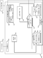
도 1은 본 발명의 교시를 구현하는 데 사용될 수 있는 예시적인 적층 제조 장치 및/또는 프린터(100)의 블록도이다. 이 예에서, 프린터(100)는 물체, 부품 등을 생성하는 데 사용될 수 있는 3D 프린터에 의해 구현된다. 예시적인 작업 영역(예를 들어, 베드)(102) 상에 예시적인 물체를 생성하기 위해, 예시된 예에서, 프린터(100)는 프린터(100)가 작업 영역(102) 상에 생성될 물체(들)를 설명하는 이미지(들) 및/또는 다른 데이터(예컨대, 파일)를 수신하는 예시적인 이미지 소스(104)를 포함한다. 일부 예에서, 작업 영역(102)은 제거 가능하다. 이러한 일부 예에서, 작업 영역(102)은 작업 영역(102)이 프린터(100)로부터 분리된 상태로 배송/출하/판매된다. 다른 예에서, 작업 영역(102)은 프린터(100)에 연결된다.1 is a block diagram of an exemplary additive manufacturing apparatus and / or
물체를 설명하는 이미지(들) 및/또는 다른 데이터에 기초하여 작업 영역(102) 상에 물체(들)를 생성하기 위해, 예시적인 빌드 제어기(106)는 작업 영역(102) 상에 빌드 재료 층(들)을 분배, 확산 및/또는 분포시키기 위해 예시적인 제1 기계장치(108)가 작업 영역(102)에 대하여 예시적인 빌드 재료 디스펜서(110)를 이동시키게 한다. 일부 예에서, 빌드 재료 디스펜서(110)는 작업 영역(102) 상에 빌드 재료 층을 분포 및/또는 분배하는 와이퍼, 롤러, 블레이드 등을 포함한다. 선택된 빌드 재료 두께 및/또는 선택된 빌드 재료의 경사도를 달성하기 위해, 빌드 재료 디스펜서(110)가 제1 기계장치(108)를 통해 이동가능하고/하거나 작업 영역(102)이 제2 기계장치(11)를 통해 이동가능하다. To create object (s) on
예시된 예에서, 빌드 재료는 예시적인 빌드 재료 공급부(112)로부터 액세스된다. 미사용 및/또는 과도한 빌드 재료가 빌드 재료 공급부(112)로 리턴될 수 있도록 하기 위해, 이 예에서, 작업 영역(102)이 빌드 재료 공급부(112)에 연결된다. 빌드 재료는 처리되지 않고 바로 빌드 재료 공급부(112)로 리턴될 수 있지만, 일부 예에서는, 빌드 재료를 빌드 재료 공급부(112)로 리턴하기 전에 일부 공정이 빌드 재료에 대해 수행된다. 도 1은 빌드 재료 디스펜서(110)가 작업 영역(102) 상에 직접 빌드 재료를 분배하는 것을 도시하지만, 다른 예에서, 빌드 재료 디스펜서(110)는 대신에 빌드 재료 분포기 및 리코터(recoater)에 의해 구현될 수 있고, 빌드 재료 분포기는 작업 영역(102)에 인접한 프린터(100)의 스테이징 영역 상에 빌드 재료를 분포하고 리코터는 작업 영역(102) 상에 빌드 재료 층(들)을 분배, 확산 및/또는 분포시킨다. 그러한 예에서, 스테이징 영역은 작업 영역(102)에 인접하고/하거나 작업 영역(102)의 일부일 수 있다.In the illustrated example, the build material is accessed from the exemplary
증착된 빌드 재료 층의 특성이 결정될 수 있도록, 예시적인 프린터(100)는 센서 데이터를 생성하는 센서(들)(113)를 포함한다. 센서(113)는 예를 들어, 스테레오 카메라, 적외선(IR) 스테레오 카메라 등과 같은 카메라로 구현될 수 있다. 그러나, 센서(113)는 형성되는 빌드 재료, 층 및/또는 물체의 메트릭(114) 및/또는 특성이 결정될 수 있게 하는 임의의 다른 방식으로 구현될 수 있다.
센서(113)가 카메라에 의해 구현되는 예에서, 센서(113)는 빌드 재료 및/또는 층의 메트릭 및/또는 특성(114)이 결정될 수 있게 하도록 예시적인 빌드 제어기(106)에 의해 처리되는 이미지 데이터(예를 들어, 센서 데이터)를 획득한다. 메트릭(114)의 일부는 빌드 재료의 최상층의 토포그래피, 작업 영역(102) 상의 빌드 재료 층의 두께, 작업 영역(102) 상에 형성되는 층 및/또는 물체를 설명하는 좌표 등을 포함할 수 있다. 좌표는, 예를 들어, 작업 영역(102) 상의 빌드 재료 및/또는 층의 치수, 픽셀 레벨 세부사항 및/또는 복셀 레벨 세부사항을 포함할 수 있다.In the example where
일부 예에서, 처리는 작업 영역(102) 상의 모든 층의 z 높이 데이터가 결정되고 그 다음에 최상층을 포함하지 않는 작업 영역(102) 상의 층들의 z 높이 데이터로부터 감산되는 센서 데이터(예컨대, 이미지 데이터)에 대한 분석을 수행하는 것을 포함한다. 달리 말하면, 작업 영역(102) 상의 현재 층(예를 들어, 최상층)(115)의 두께는, 빌드 재료의 현재 층(115)(예를 들어, 현재 층(115)을 포함하여 작업 영역(102) 상의 모든 층)이 작업 영역(102) 상에 증착된 후 빌드 재료의 상부 층(예를 들어, 현재 층)(115)이 작업 영역(102) 상의 물체의 z 높이로부터 증착되기 전에, 작업 영역(102) 상의 물체(예를 들어, 현재 층(115)을 제외한 작업 영역(102) 상의 모든 층)의 z 높이를 감산함으로써 결정될 수 있다. 일부 예에서, 빌드 제어기(106)는 생성된 및/또는 생성되고 있는 물체를 나타내는(예를 들어, 시각적으로 나타내는) 데 사용될 수 있는 모델(117)을 발생 및/또는 업데이트한다. 모델(117)을 분석하고 및/또는 모델(117)의 데이터를 참조 데이터 및/또는 메트릭(119)과 비교함으로써, 자격조건이 형성되는 층 및/또는 물체가 품질 임계값을 만족시킨다는 것을 나타낼 때 예시적인 프린터(100)에 의해 형성되는 물체에 자격을 주는 데 모델(117)이 사용될 수 있다. 일부 예에서, 참조 데이터(114)는 형성되는 물체와 관련된 데이터를 포함하고, 센서 데이터는 센서(113)로부터 액세스된 처리되지 않은 데이터(예를 들어, 이미지 데이터)를 포함하며 결정된 메트릭(114)은 예를 들어, 층(115)의 토포그래피, 층(115)의 치수, 형성되는 물체의 치수 및/또는 특성 등을 설명하는 데이터를 포함하는 센서 데이터를 처리한 결과를 포함한다.In some examples, processing includes sensor data (eg, image data) from which z height data of all layers on the
작업 영역(102)의 현재 층(115)이 이미지(들) 및/또는 다른 데이터에 의해 설명된 관련 층의 임계값 내에 있는지를 판정하기 위해, 일부 예에서, 빌드 제어기(106)는 모델(117)로부터 결정된 메트릭(114)을 데이터 저장 디바이스(120)로부터의 참조 데이터(119)와 비교한다. 이 예에서, 메트릭(114), 모델(117) 및 참조 데이터(119)는 데이터 저장 디바이스(120)에 저장된다. 작업 영역(102) 상에 형성되는 현재 층(115) 및/또는 물체의 메트릭(114)이 참조 데이터(119)의 임계값을 만족시키는 예에서, 빌드 제어기(106)는 층을 참조 데이터(119)를 만족시키는 것으로 연관시킨다. 작업 영역(102) 상에 형성되는 현재 층(115) 및/또는 물체의 메트릭(114)이 참조 데이터(119)의 임계값을 만족시키지 않는 예에서, 빌드 제어기(106)는 층을 참조 데이터(119)를 만족시키지 않는 것으로 연관시킨다. 부가적으로 및/또는 대안적으로, 작업 영역(102) 상에 형성되는 현재 층(115) 및/또는 물체의 메트릭(114)이 참조 데이터(119)의 임계값을 만족시키지 않는 예에서, 빌드 제어기(106)는 적층 제조 공정을 계속할지 여부를 판정한다. In order to determine if the
현재 층(115)의 메트릭(114)이 현재 층(115) 및/또는 물체 자체가 품질 임계값을 만족시키지 못하게 하는 특성(들)을 갖고 그 특성(들)이 수정 불가한 것으로 결정되는 예에서, 빌드 제어기(106)는 형성되는 물체를 거부하고/하거나 적층 제조 공정을 계속하지 않기로 결정할 수 있다. 이와 달리, 현재 층(115)의 메트릭 (114)이 현재 층(115) 및/또는 물체 자체가 임계값을 만족시키지 못하게 하는 특성(들)을 갖고 그 특성(들)이 수정가능한 것으로 결정되는 예에서, 빌드 제어기(106)는 적층 제조 공정을 계속하기로 결정할 수 있다. In the example where the metric 114 of the
일부 예에서, 빌드 제어기(106)는 제1 기계장치(108)가 작업 영역(102)에 대해 예시적인 빌드 재료 디스펜서(110)를 이동시키게 하여 작업 영역(102) 상의 빌드 재료의 최상층의 특성을 변경시킴으로써, 특성(들)을 수정한다. 일부 예에서, 빌드 제어기(106)는 제2 기계장치(111)가 예시적인 작업 영역(102)을 이동시키게 하여 작업 영역(102) 상의 빌드 재료의 최상층의 특성이 빌드 재료 디스펜서(110)가 작업 영역(102)에 대해 이동되기 전에, 동안에, 및/또는 후에 변경되게 함으로써 특성(들)을 수정한다.In some examples, the
빌드 재료가 선택적으로 융해되고/되거나 층의 특성(들)을 수정하는 방법을 계획하기 위해, 빌드 제어기(106)는 복수의 주입 프로파일(123) 중에서 주입 프로파일을 선택한다. 이 예에서, 주입 프로파일(123)은 데이터 저장 디바이스(120)에 저장된다. 주입 프로파일은 결정된 메트릭(114), 빌드 재료 및/또는 층(115)과 연관될 수 있다. 일부 예에서, 주입 프로파일은 빌드 재료 층(115) 상에 작용제를 더 많이 또는 더 적게 증착시킬 수 있고/있거나 빌드 재료가 선택적으로 함께 융해되게 할 때 더 많거나 적은 에너지가 빌드 재료 층(115)에 인가되게 할 수 있다. 예를 들어, 빌드 층 내의 위치(X, Y) 근처의 분말 층 두께의 국부적 증가가 검출되면, 주입 프로파일(예를 들어, 선택된 주입 프로파일, 생성된 주입 프로파일)은 더 많은 융해제/에너지가 위치(X, Y)에 인접하게 인가되게 하여 완전한 융해를 가능하게 하고/하거나 보장할 수 있다. 다른 예에서, 빌드 층 내의 위치(X, Y) 근처의 분말 층 두께의 국부적 감소가 검출되면, 주입 프로파일(예를 들어, 선택된 주입 프로파일, 생성된 주입 프로파일)은 위치(X, Y)에 인접하는 곳에서 융해제/에너지의 양이 감소하게 하여 위치(X, Y)에 인접하는 곳(예를 들어, 측정이 얇은 분말 구역을 나타내는 곳)에서 유체(예를 들어, 너무 많은 유체 추가)가 범람하는 것 및/또는 위치(X, Y)에 인접하는 부품의 과열을 방지할 수 있다. 다시 말해서, 물리적 빌드 공정에서 편차가 검출되면, 일부 예에서, 입력 파라미터는 상황에 기초하여 원하는 결과를 달성하도록 변경된다. 일부 예에서, 인가되는 작용제/에너지의 양은 예를 들어, 측정된 빌드 메트릭 편차 및 재료 특성의 함수로서 유체 침투 깊이/용융 깊이를 추정하는 방정식/모델을 사용하여 결정된다. 일부 재료 특성은 유체 침투 계수, 열 전달 계수, 융점 등을 포함할 수 있다. 일부 예에서, 가정 및/또는 추정된 빌드 메트릭에 기초하여 이들 파라미터에 대한 초기 값을 결정하기 위해 모델로부터 결과가 추론된다.To plan how the build material selectively melts and / or modifies the layer's property (s),
작용제가 빌드 재료 층(115) 상에 분배될 수 있게 하기 위해, 빌드 제어기(106)는 예시적인 제3 기계장치(122)가 작업 영역(102)에 대해 예시적인 프린트헤드(126) 및 노즐(128)을 포함하는 예시적인 작용제 디스펜서(124)를 빌드 재료 층(115) 맨 위로 이동시킨다. 일부 예에서, 노즐(128)이 제3 기계장치(122)에 의해 이동될 때 선택된 주입 프로파일에 따라 빌드 재료 상에 작용제를 증착한다.To enable the agent to be dispensed on the
예시된 예에서, 작용제 디스펜서(124) 및/또는 프린트헤드(126)는 예시적인 작용제 공급부(130)로부터 작용제를 인출하고/하거나 액세스한다. 작용제 공급부(130)는 작용제(들)(예를 들어, 1, 2, 3, 4 유형의 작용제) 및/또는 적층 제조 공정 동안 사용된 다른 액체(들)를 수용하는 챔버(들)(예를 들어, 1, 2, 3 등)를 포함할 수 있다. 일부 예에서, 작용제는 융해제, 상세 작용제, 정확성 및/또는 세부사항과 관련된 작용제(들), 불투명 및/또는 반투명과 관련된 작용제(들) 및/또는 표면 거칠기, 질감 및/또는 마찰과 관련된 작용제(들)를 포함한다. 추가적으로 또는 대안적으로, 일부 예에서, 작용제는 강도, 탄성 및/또는 다른 재료 속성과 관련된 작용제(들), 색(예를 들어, 표면 및/또는 내장)과 관련된 작용제(들) 및/또는 전기 및/또는 열 전도성과 관련된 작용제(들)를 포함한다.In the illustrated example, the
일부 예들에서, 노즐(128)이 빌드 재료 상에 작용제를 선택적으로 증착하는 동안 및/또는 후에, 센서(113)는 이미지 데이터를 획득하고/하거나 빌드 제어기(106)는 작용제 디스펜서(124) 및/또는 생성되는 물체, 프린트헤드(126) 및/또는 노즐(128)에 액세스한다. 빌드 제어기(106)는 데이터를 처리하여 증착되는 작용제의 작용제 분배 특성(들), 작용제 디스펜서(124), 프린트헤드(126) 및/또는 노즐(128)의 동작 특성을 결정한다.In some examples, while and / or after
증착된 작용제가 대응하는 참조 주입 프로파일의 임계값을 만족시키는지를 판정하기 위해, 일부 예에서, 빌드 제어기(106)는 작용제 분배 특성을 데이터 저장 디바이스(120)로부터 선택된 주입 프로파일과 연관된 참조 데이터(119)와 비교한다. 결정된 작용제 분배 특성이 참조 데이터(119)의 임계값을 만족시키는 예에서, 빌드 제어기(106)는 빌드 재료의 현재 층(115)의 작용제 분배 특성을 참조 데이터(119)를 만족시키는 것으로 연관시킨다. 결정된 작용제 분배 특성이 참조 데이터(119)의 임계값을 만족시키지 않는 예에서, 빌드 제어기(106)는 빌드 재료의 현재 층(115)의 작용제 분배 특성을 참조 데이터(119)를 만족시키지 않는 것으로 연관시킨다. To determine if the deposited agent satisfies a threshold of a corresponding reference injection profile, in some examples, build
빌드 제어기(106)가 빌드 재료의 현재 층(115)의 작용제 분배 특성을 참조 데이터(119)를 만족시키지 않는 것으로 연관시키는 예에서, 빌드 제어기(106)는 연관된 주입 프로파일을 업데이트 및/또는 선택하고/하거나, 적층 제조 공정을 계속할지 여부를 판정한다. 예를 들어, 주입 프로파일을 업데이트(예를 들어, 수정, 변경)하는 것은 추가 작용제가 빌드 재료의 층(115) 상에 분배되게 하고/하거나 더 많거나 적은 에너지가 빌드 재료의 층(115)에 인가되게 하는 것을 포함할 수 있다. 일부 예에서, 주입 프로파일을 업데이트하는 것은 빌드 제어기(106)가 참조 데이터(119)와의 차이 및/또는 편차 및/또는 형성되는 층 및/또는 물체의 예상 특성 및/또는 메트릭을 설명하기 위해 선택된 주입 프로파일을 업데이트하는 것을 포함한다. 따라서, 본 명세서에 개시된 예를 사용하여, 빌드 제어기(106)는 예상 결과(예를 들어, 소정 특성을 갖는 후속 생성 물체, 소정 특성을 갖는 실질적으로 생성된 층 등)가 달성될 수 있도록 주입 프로파일이 업데이트되게 하는 자체 학습중이다. 앞선 예는 작용제 분배 특성을 결정하고 참조 데이터와 비교하는 것을 언급하지만, 다른 예에서, 빌드 제어기(106)는 추가로 또는 대안적으로 결정된 메트릭(114)을 참조 데이터(119)와 비교하여 형성되는 층 및/또는 물체가 품질 임계값을 만족시키는지를 판정한다. 이러한 일부 예에서, 주입 프로파일은 생성된 층 및/또는 물체가 예상과 다를 때 업데이트된다. In an example where
도시된 예에서, 작용제가 층(115)에 도포된 빌드 재료를 선택적으로 융해 및/또는 응고시키기 위해, 빌드 재료 제어기(106)는 제1 기계장치(108)가 선택된 주입 프로파일에 따라 작업 영역(102)에 대해 예시적인 에너지원(132)을 이동시키게 하고 선택된 주입 프로파일에 따라 작업 영역(102) 상의 빌드 재료에 에너지를 인가하게 한다. 에너지원(132)은 임의의 유형의 에너지를 인가하여 빌드 재료가 선택적으로 융해 및/또는 응고되게 할 수 있다. 예를 들어, 에너지원(132)은 적외선(IR) 광원, 근적외선 광원, 레이저 등을 포함할 수 있다. 도 1에는 에너지원이 빌드 재료 디스펜서(110)에 인접하게 위치되고 제1 기계장치(108)에 의해 이동되는 것으로 도시되어 있지만, 다른 예에서, 에너지원(132)은 작용제 디스펜서(124)에 인접하여 위치되고 제3 기계장치(122)에 의해 이동될 수 있다. 다른 예에서, 에너지원(132)은 전용 기계장치에 의해 이동될 수 있고 작업 영역(102)에 대해 고정으로 배치될 수 있다. In the example shown, in order to selectively melt and / or solidify the build material to which the agent has been applied to the
일부 예에서, 에너지원(132)이 빌드 재료 상에 에너지를 방출하는 동안 및/또는 후에, 센서(113)는 이미지 데이터를 획득하고/하거나 빌드 제어기(106)는 에너지원(132) 및/또는 생성되는 물체와 연관된 데이터에 액세스한다. 이 예에서, 데이터는 예시적인 빌드 제어기(106)에 의해 처리되어 작업 영역(102)에 인가된 에너지의 에너지 방출 특성(들)을 결정한다. 빌드 재료의 현재 층(115)에 인가된 에너지가 대응하는 참조 주입 프로파일의 임계값을 만족시키는지 여부를 판정하기 위해, 일부 예에서, 빌드 제어기(106)는 에너지 방출 특성을 데이터 저장 디바이스(120)로부터 선택된 주입 프로파일과 관련된 참조 데이터(119)와 비교한다. 결정된 에너지 방출 특성이 참조 데이터(119)의 임계값을 만족시키는 예에서, 빌드 제어기(106)는 빌드 재료의 현재 층(115)의 에너지 방출 특성을 참조 데이터(119)를 만족시키는 것으로 연관시킨다. 에너지 방출 특성이 참조 데이터(119)의 임계값을 만족시키지 않는 예에서, 빌드 제어기(106)는 빌드 재료의 현재 층(115)의 에너지 방출 특성을 참조 데이터(119)를 만족시키지 않는 것으로 연관시킨다. 빌드 제어기(106)가 빌드 재료의 현재 층(115)의 에너지 방출 특성을 참조 데이터(119)를 만족시키지 않는 것으로 연관시키는 예에서, 빌드 제어기(106)는 연관된 주입 프로파일을 업데이트 및/또는 선택하고/하거나, 적층 제조 공정을 계속할지 여부를 판정한다. 주입 프로파일을 업데이트하는 것은 빌드 재료 층의 하나 또는 복수의 부분에 더 많은 에너지가 인가되게 하는 것을 포함할 수 있다. 일부 예에서, 주입 프로파일을 업데이트하는 것은 빌드 제어기(106)가 참조 데이터(119)와의 차이 및/또는 편차 및/또는 형성되는 층 및/또는 물체의 예상 특성 및/또는 메트릭을 설명하기 위해 선택된 주입 프로파일을 업데이트하는 것을 포함한다. 따라서, 본 명세서에 개시된 예를 사용하여, 빌드 제어기(106)는 예상 결과(예를 들어, 소정 특성을 갖는 후속 생성 물체 등)가 달성될 수 있도록 주입 프로파일이 업데이트되게 하는 자체 학습중이다. 앞선 예는 에너지 방출 특성을 결정하고 참조 데이터(119)와 비교하는 것을 언급하지만, 다른 예에서, 빌드 제어기(106)는 추가로 또는 대안적으로 결정된 메트릭(114)을 참조 데이터(119)와 비교하여 생성되는 층 및/또는 물체가 품질 임계값을 만족시키는지를 판정한다. 이러한 일부 예에서, 주입 프로파일은 생성된 층 및/또는 물체가 예상과 다를 때 업데이트된다. In some examples, while and / or after the
예시된 예에서, 도 1의 예시적인 프린터(100)는 이미지 소스(104)와 인터페이싱하기 위한 인터페이스(134)를 포함한다. 인터페이스(134)는 프린터(100)와 이미지 소스(104)를 연결하는 유선 또는 무선 접속일 수 있다. 이미지 소스(104)는 프린터(100)가 빌드 제어기(106)에 의해 실행될 태스크(예를 들어, 형성할 물체, 인쇄 작업 등)를 설명하는 데이터를 수신하는 컴퓨팅 디바이스일 수 있다. 일부 예에서, 인터페이스(134)는 프린터(100) 및/또는 빌드 제어기(106)가 이미지 소스(104) 및/또는 프린터(100)의 외부 및/또는 내부의 하드웨어 요소와 같은 다양한 하드웨어 요소와 인터페이싱하는 것을 가능하게 한다. 일부 예에서, 인터페이스(134)는 예를 들어, 디스플레이 디바이스, 마우스, 키보드 등과 같은 입력 또는 출력 디바이스와 인터페이싱한다. 인터페이스(134)는 외부 저장 디바이스와 같은 다른 외부 디바이스, 예를 들어, 서버, 스위치, 라우터와 같은 네트워크 디바이스, 클라이언트 디바이스, 다른 유형의 컴퓨팅 디바이스 및/또는 이들의 조합에 대한 액세스도 제공할 수 있다.In the illustrated example, the
일부 예에서, 예시적인 빌드 제어기(106)는 예시적인 데이터 저장 디바이스(120)로부터 실행가능 코드를 불러오고 실행하기 위한 하드웨어 아키텍처를 포함한다. 실행가능 코드는, 빌드 제어기(106)에 의해 실행될 때, 물체를 설명하는 이미지(들) 및/또는 다른 데이터 및/또는 선택된 주입 프로파일에 기초하여 빌드 제어기(106)가 적어도 제1 기계장치(108)를 제어하는 기능을 구현하고/하거나 빌드 재료 디스펜서(110)가 작업 영역(102) 상에 빌드 재료를 분배하게 할 수 있다. 실행가능 코드는, 빌드 제어기(106)에 의해 실행될 때, 물체를 설명하는 이미지(들) 및/또는 다른 데이터 및/또는 선택된 주입 프로파일에 기초하여 빌드 제어기(106)가 적어도 제2 기계장치(111)를 제어하는 기능을 구현하고/하거나 연관된 프린트헤드(126) 및 노즐(128)을 포함하는 작용제 디스펜서(124)가 빌드 재료에 작용제를 분배하게 할 수 있다. 실행가능 코드는, 빌드 제어기(106)에 의해 실행될 때, 물체를 설명하는 이미지(들) 및/또는 다른 데이터 및/또는 선택된 주입 프로파일에 기초하여 빌드 제어기(106)가 적어도 제1 기계장치(108)를 제어하는 기능을 구현하고/하거나 작업 영역(102) 상의 빌드 재료에 에너지를 인가하는 에너지원(132)이 물체(들)를 형성하게 한다. 실행가능 코드는, 빌드 제어기(106)에 의해 실행될 때, 빌드 제어기(106)가 형성되는 층(115) 및/또는 물체의 메트릭(114)에 기초하여 주입 프로파일을 선택 및/또는 업데이트하게 하여 본 명세서에 개시된 예를 사용하여 생성된 물체(예를 들어, 현재 생성 물체, 후속 생성 물체 등)가 품질 임계값을 만족시킬 수 있다. 실행가능 코드는, 빌드 제어기(106)에 의해 실행될 때, 부품이 품질 임계값을 만족시키지 않으면 빌드 제어기(106)가 경보를 생성하고/하거나 생성되는 부품을 거부하게 할 수 있다. 실행가능 코드는, 예시적인 빌드 제어기(106)에 의해 실행될 때, 빌드 제어기(106)가 예시적인 전원 공급 유닛(138)에 명령어를 제공하게 할 수 있는데, 이는 전원 공급 유닛(138)이 예시적인 프린트헤드(126)에 예시적인 노즐(들)(128)로부터 액체를 토출시키기 위한 전력을 제공하게 하기 위한 것이다.In some examples,
도 1의 데이터 저장 디바이스(120)는 빌드 제어기(106) 또는 다른 처리 디바이스에 의해 실행되는 명령어를 저장한다. 예시적인 데이터 저장 디바이스(120)는 예시적인 빌드 제어기(106)가 본 명세서에 개시된 예를 구현하기 위해 실행하는 다수의 애플리케이션, 펌웨어, 머신 판독가능 명령어 등을 나타내는 컴퓨터 코드를 저장할 수 있다.The
도 2는 도 1의 예시적인 빌드 제어기(106)의 예시적인 구현예를 도시한다. 도 2에 도시된 바와 같이, 빌드 제어기(106)는 예시적인 빌드 재료 분포 프로파일 결정기(202), 예시적인 빌드 재료 디스펜서 제어기(203), 예시적인 빌드 메트릭 결정기(204), 예시적인 모델러(206), 예시적인 비교기(208), 예시적인 업데이트기(209), 예시적인 품질 결정기(210), 예시적인 주입 프로파일 결정기(211), 예시적인 작업 영역 위치 제어기(212), 예시적인 작용제 디스펜서 제어기(214) 및 예시적인 에너지원 제어기(216)를 포함한다.2 shows an example implementation of the
예시된 예에서, 작업 영역(102) 및/또는 작업 영역(102) 상의 빌드 재료의 상부 층 상의 빌드 재료 분포 차이 및/또는 불일치를 보상하기 위해, 빌드 재료 분포 프로파일 결정기(202)는 빌드 재료 디스펜서(110)에 의해 분포될 빌드 재료를 식별하고, 빌드 재료 디스펜서(110)가 작업 영역(102) 상에 지시되고/되거나 선택된 빌드 재료 경사도 및/또는 층을 제공하게 하는 빌드 재료 분포 프로파일을 결정한다. 빌드 재료 분포 프로파일 결정기(202)가 제1 빌드 재료 유형이 분포될 것이라고 결정하면, 빌드 재료 디스펜서(110)는 작업 영역(102) 상에 빌드 재료를 분포시킬 때 제1 속도로 작업 영역(102)의 맨 위로 이동하고, 빌드 재료 분포 프로파일 결정기(202)가 제2 빌드 재료 유형이 분포될 것이라고 결정하면, 빌드 재료 디스펜서(110)는 작업 영역(102) 상에 빌드 재료를 분포시킬 때 제2 속도로 작업 영역(102)의 맨 위로 이동할 수 있다. 부가적으로 또는 대안적으로, 빌드 재료 분포 프로파일 결정기(202)가 빌드 재료 디스펜서(110)가 작업 영역의 제2 측면에 비해 작업 영역(102)의 제1 측면 상에 실수로 더 많은 빌드 재료를 분포시킨다고 결정하면, 빌드 재료 분배 프로파일 결정기(202)는, 빌드 재료 디스펜서 제어기(203)에 의해 실행될 때, 빌드 재료 디스펜서(110)가 제1 속도로 이동하게 하고/하거나 작업 영역(102)의 제1 측면 위에 제1 양의 빌드 재료를 분포시키게 하고 제2 속도로 이동하게 하고/하거나 작업 영역(102)의 제2 측면 위에 제2 양의 빌드 재료를 분포시키게 하는 빌드 재료 분포 프로파일을 결정, 업데이트 및/또는 선택할 수 있다. 다시 말하면, 빌드 재료 분포 프로파일은 빌드 재료 디스펜서(110)가 선택된 빌드 재료 프로파일에 따라 불균일한 방식 및/또는 균일한 방식으로 작업 영역(102) 상에 빌드 재료를 분포시키게 할 수 있다. 앞선 예는 작업 영역(102) 상에 빌드 재료의 지시된 경사도를 달성하기 위해 상이한 속도로 빌드 재료 디스펜서(110)를 이동시키는 것을 언급하지만, 작업 영역(102) 상에 빌드 재료를 선택적으로 분배, 확산 및/또는 분포시키기 위해 임의의 다른 방법이 사용될 수 있다.In the illustrated example, to compensate for build material distribution differences and / or discrepancies on the
빌드 메트릭 결정기(204)는 센서(113), 제1 기계장치(108) 및/또는 빌드 재료 디스펜서(110)로부터의 데이터에 액세스하고 그 데이터를 처리하여 작업 영역(102) 상의 빌드 재료 층의 메트릭(114)을 결정한다. 메트릭(114)은 빌드 재료의 최상층의 토포그래피, 빌드 재료 및/또는 최상층의 두께, 국부적 치수를 포함하는 최상층의 치수, 작업 영역(102) 상에 형성되는 층 및/또는 이의 토포그래피 및/또는 물체를 설명하는 좌표 등을 포함할 수 있다. 일부 예에서, 메트릭(114)은 작업 영역(102) 상의 층 및/또는 빌드 재료에 대한 픽셀 레벨 세부사항 및/또는 복셀 레벨 세부사항을 포함한다. 물론, 메트릭(114)은 발생하는 적층 제조 공정과 관련된 임의의 추가 및/또는 대안 데이터를 포함할 수 있다.The build
모델러(206)는 결정된 메트릭(114)과 형성되는 현재 층(115) 및/또는 물체를 연관 및/또는 매핑하는 모델(114)을 생성 및/또는 업데이트한다. 일부 예에서, 모델(117)은 층이 형성되었던 시간, 층(들)을 나타내고/내거나 이에 관한 좌표(X, Y, Z 좌표) 및/또는 층(들) 및/또는 물체 자체의 토포그래피에 대한 세부 사항을 포함한다. 부가적으로 또는 대안적으로, 모델(117) 및/또는 관련 데이터(예를 들어, 좌표)는 z 축에서 축적된 특징부 이동의 맵, 키홀의 맵 및/또는 빌드 평면(들) 내의 빌드 재료 두께 맵을 생성하는 데 사용될 수 있다.The
작업 영역(102) 상의 빌드 재료의 현재 층(115)의 메트릭(114)이 대응하는 참조 데이터(119)의 임계값 내에 있는지를 판정하기 위해, 비교기(208)는 결정된 메트릭(114)과 데이터 저장 디바이스(120)로부터 참조 데이터(119)를 비교하고, 품질 결정기(210)는 결정된 메트릭(114)이 참조 데이터(114)의 임계값 내에 있는지를 판정한다. 작업 영역(102) 상에 형성되는 현재 층(115) 및/또는 물체의 메트릭(114)이 참조 데이터(119)의 임계값을 만족시키는 예에서, 품질 결정기(210)는 층을 참조 데이터(119)를 만족시키는 것으로 연관시키고, 모델러(206)는 그에 따라 모델(117)을 업데이트한다. 추가적으로 또는 대안적으로, 작업 영역(102) 상에 형성되는 현재 층(115) 및/또는 물체의 메트릭(114)이 참조 데이터(119)의 임계값을 만족시키는 예에서, 업데이트기(209)는 선택된 분배 프로파일을 예상 및/또는 원하는 결과를 달성 및/또는 만족시키는 것으로 연관시킨다.To determine if the metric 114 of the
추가적으로 또는 대안적으로, 작업 영역(102) 상에 형성되는 현재 층(115) 및/또는 물체의 메트릭(114)이 참조 데이터(119)의 임계값을 만족시키지 않는 예에서, 업데이트기(209)는 선택된 빌드 재료 분배 프로파일은 예상 결과를 달성 및/또는 만족시키지 않는 것으로 연관시키고/시키거나 선택된 빌드 재료 분배 프로파일을 이에 따라 업데이트한다. 선택된 빌드 재료 분배 프로파일은 선택된 빌드 재료 분배 프로파일과 관련된 분배 특성을 점진적으로 및/또는 변경함으로써 업데이트되어 원하는 및/또는 예상 빌드 재료 분배 프로파일이 미래 및/또는 후속 빌드 중에 달성되게 할 수 있다. 작업 영역(102) 상에 형성되는 현재 층(115) 및/또는 물체의 메트릭(114)이 참조 데이터(119)의 임계값을 만족시키지 않는 예에서, 품질 결정기(210)는 층을 참조 데이터(119)를 만족시키지 않는 것으로 연관시키고 모델러(206)는 이에 따라 모델(117)을 업데이트한다. 작업 영역(102) 상에 형성되는 현재 층(115) 및/또는 물체의 메트릭(114)이 참조 데이터(119)의 임계값을 만족시키지 않는 예에서, 품질 결정기(210)는 적층 제조 공정을 계속할지 여부를 판정한다. 메트릭(114)이 참조 데이터(114)의 임계값을 만족시키지 않고 품질 결정기(210)가 발생한 빌드가 수정될 수 없다고 결정할 때, 일부 예에서, 품질 결정기(210)는 형성되는 물체를 거부할 수 있고/있거나 적층 제조 공정을 계속하지 않을 수 있다.Additionally or alternatively, in the example where the metric 114 of the
메트릭(114)이 참조 데이터(119)의 임계값을 만족시키지 않고 품질 결정기(210)가 발생한 빌드가 수정 가능하다고 결정하면, 일부 예에서, 빌드 재료 디스펜서 제어기(203)는 빌드 재료 디스펜서(110)가 현재 층(115)의 두께 및/또는 현재 층(115)의 토포그래피/경사도를 변경하게 한다. 부가적으로 및/또는 대안적으로, 품질 결정기(210)가 발생한 빌드가 수정 가능하다고 결정할 때, 일부 예에서, 작업 영역 위치 제어기(212)는 빌드 재료 디스펜서(110)가 현재 층(115)의 두께 및/또는 토포그래피/경사도를 변경하도록 작업 영역(102)이 그 위치를 변경하게 한다. 이러한 일부 예에서, 빌드 재료 디스펜서(110)가 현재 층(115)의 메트릭(들)을 변경한 후, 센서(113)는 업데이트된 이미지 데이터를 획득하고, 빌드 메트릭 결정기(204)는 빌드되는 층 및/또는 물체의 업데이트된 메트릭을 결정하며 모델러(206)는 업데이트된 메트릭으로 모델(117)을 업데이트한다. 추가적으로 또는 대안적으로, 빌드 재료 디스펜서(110)가 현재 층(115)의 메트릭(들)을 변경한 후, 비교기(208)는 업데이트된 메트릭을 참조 데이터(119)와 비교하고 품질 결정기(210)는 업데이트된 메트릭이 참조 데이터(119)의 임계값을 만족하는지를 판정한다.If the metric 114 does not satisfy the threshold of the
품질 결정기(210)가 발생한 빌드가 수정 가능하다고 결정할 때 및/또는 품질 결정기(210)가 결정된 메트릭(114)이 참조 데이터(119)의 임계값을 만족한다고 판정할 때, 주입 프로파일 결정기(211)는 예시적인 작용제 분배 프로파일 및/또는 에너지 방출 프로파일을 포함하는 예시적인 주입 프로파일을 결정한다. 일부 예에서, 작용제 분배 프로파일은 작업 영역(102)의 구역(들)에 일정량의 작용제를 증착하기 위한 명령어를 포함한다. 일부 예에서, 에너지 방출 프로파일은 작업 영역(102)의 구역(들) 상의 일정량의 에너지를 방출하기 위한 명령어를 포함한다. 분배된 작용제의 양 및/또는 방출되는 에너지의 양은 작업 영역(102)의 구역마다 다를 수 있다. The
일부 예에서, 빌드 재료가 선택적으로 융해 및/또는 결합되어 물체(들)를 형성할 수 있도록 하기 위해, 일부 예에서, 에이전트 디스펜서 제어기(214)는 연관된 예시적인 프린트헤드(126) 및 노즐(128)을 포함하는 에이전트 디스펜서(124)가 작업 영역(102)에 대해 이동하게 하고 주입 프로파일에 따라 빌드 재료 상에 작용제를 분배하게 한다. 또한, 일부 예에서, 빌드 재료가 선택적으로 융해 및/또는 결합되어 물체(들)를 형성할 수 있게 하기 위해, 에너지원 제어기(216)는 에너지원(132)이 작업 영역(102)에 대해 이동하게 하고 주입 프로파일에 따라 빌드 재료 상에 에너지를 방출하게 한다.In some examples, in order to allow build materials to selectively melt and / or combine to form object (s), in some examples,
작업 영역(102) 상의 빌드 재료의 현재 층(115)의 메트릭(114)이 대응하는 참조 데이터(119)의 임계값 내에 있는지 및/또는 형성되는 물체가 참조 데이터(119)의 임계값을 만족시키는지를 결정하기 위해, 빌드 메트릭 결정기(204)는 센서(113), 제1 기계장치(108), 빌드 재료 디스펜서(110), 에너지원(132), 제2 기계장치(111), 제3 기계장치(122), 작용제 디스펜서(124), 프린트헤드(126) 및/또는 노즐(128)로부터의 데이터에 액세스하고, 그 데이터를 처리하여 융해된 빌드 재료 층 및/또는 작업 영역(102) 상에 형성된 물체 자체의 메트릭(114)을 결정한다.Whether the metric 114 of the
메트릭(114)이 참조 데이터(114)의 임계값 내에 있는지를 판정하기 위해, 비교기(208)는 결정된 메트릭(114)과 참조 데이터(119)를 비교하고 품질 결정기(210)는 결정된 메트릭(114)이 참조 데이터(119)의 임계값 내에 있는지를 판정한다. 작업 영역(102) 상에 형성되는 현재 층(115) 및/또는 물체의 메트릭(114)이 참조 데이터(119)의 임계값을 만족시키는 예에서, 품질 결정기(210)는 층을 참조 데이터(119)를 만족시키는 것으로 연관시키고, 모델러(206)는 그에 따라 모델(117)을 업데이트한다. 추가적으로 또는 대안적으로, 작업 영역(102) 상에 형성되는 현재 층(115) 및/또는 물체의 메트릭(114)이 참조 데이터(119)의 임계값을 만족시키는 예에서, 업데이트기(209)는 선택된 주입 프로파일을 예상 및/또는 원하는 결과를 달성 및/또는 만족시키는 것으로 연관시킨다. To determine if the metric 114 is within the threshold of the
작업 영역(102) 상에 형성되는 현재 층(115) 및/또는 물체의 메트릭(114)이 참조 데이터(119)의 임계값을 만족시키지 않는 예에서, 품질 결정기(210)는 층을 참조 데이터(119)를 만족시키지 않는 것으로 연관시키고 모델러(206)는 이에 따라 모델(117)을 업데이트한다. 추가적으로 또는 대안적으로, 작업 영역(102) 상에 형성되는 현재 층(115) 및/또는 물체의 메트릭(114)이 참조 데이터(119)의 임계값을 만족시키지 않는 예에서, 업데이트기(209)는 선택된 주입 프로파일을 업데이트하여 후속 층 및/또는 후속 빌드가 예상 및/또는 원하는 결과를 달성 및/또는 만족시킬 수 있게 한다. 다시 말해서, 선택된 주입 프로파일이 예상 결과를 달성하지 않을 때, 일부 예에서, 주입 프로파일이 업데이트된다. In an example in which the
도 1의 빌드 제어기(106)를 구현하는 예시적인 방식이 도 2에 도시되지만, 도 2에 도시된 요소, 프로세스 및/또는 디바이스 중 임의의 하나는 결합, 분할, 재배열, 생략, 제거 및/또는 임의의 다른 방식으로 구현될 수 있다. 또한, 예시적인 빌드 재료 분포 프로파일 결정기(202), 예시적인 빌드 재료 디스펜서 제어기(203), 예시적인 빌드 메트릭 결정기(204), 예시적인 모델러(206), 예시적인 비교기(208), 예시적인 업데이트기(209), 예시적인 품질 결정기(210), 예시적인 주입 프로파일 결정기(211), 예시적인 작업 영역 위치 제어기(212), 예시적인 작용제 디스펜서 제어기(214), 예시적인 에너지원 제어기(216) 및/또는, 보다 일반적으로, 도 1의 예시적인 빌드 제어기(106)는 하드웨어, 소프트웨어, 펌웨어 및/또는 하드웨어, 소프트웨어 및/또는 펌웨어의 임의의 조합에 의해 구현될 수 있다. 따라서, 예를 들어, 예시적인 빌드 재료 분포 프로파일 결정기(202), 예시적인 빌드 재료 디스펜서 제어기(203), 예시적인 빌드 메트릭 결정기(204), 예시적인 모델러(206), 예시적인 비교기(208), 업데이트기(209), 예시적인 품질 결정기(210), 예시적인 주입 프로파일 결정기(211), 예시적인 작업 영역 위치 제어기(212), 예시적인 작용제 디스펜서 제어기(214), 예시적인 에너지원 제어기(216) 및/또는, 보다 일반적으로, 도 1의 예시적인 빌드 제어기(106) 중 임의의 것은 아날로그 또는 디지털 회로(들), 로직 회로, 프로그램 가능 프로세서(들), 주문형 집적 회로(들)(ASIC(s)), 프로그램 가능 로직 디바이스(들)(PLD(s)) 및/또는 필드 프로그램 가능 로직 디바이스(들)(FPLD(s))에 의해 구현될 수 있다. 소프트웨어 및/또는 펌웨어 구현만을 커버하기 위해 본 특허의 장치 또는 시스템 청구항 중 임의의 것을 읽을 때, 예시적인 빌드 재료 분포 프로파일 결정기(202), 예시적인 빌드 재료 디스펜서 제어기(203), 예시적인 빌드 메트릭 결정기(204), 예시적인 모델러(206), 예시적인 비교기(208), 예시적인 업데이트기(209), 예시적인 품질 결정기(210), 예시적인 주입 프로파일 결정기(211), 예시적인 작업 영역 위치 제어기(212), 예시적인 작용제 디스펜서 제어기(214), 예시적인 에너지원 제어기(216) 및/또는, 보다 일반적으로, 도 1의 예시적인 빌드 제어기(106) 중 적어도 하나는 소프트웨어 및/또는 펌웨어를 저장하는 메모리, 디지털 다기능 디스크(DVD), 콤팩트 디스크(CD), 블루레이 디스크 등과 같은 유형의 컴퓨터 판독가능 저장 디바이스 또는 저장 디스크를 포함하도록 명시적으로 정의된다. 더 나아가, 도 1의 예시적인 빌드 제어기(106)는 도 2에 도시된 것들에 부가하여 또는 그 대신에 요소(들), 프로세스(들) 및/또는 디바이스를 포함할 수 있고/있거나 도시된 요소, 프로세스 및 디바이스 중 임의의 것 중 하나보다 많이 또는 전부를 포함할 수 있다. Although an exemplary manner of implementing the
도 1의 빌드 제어기(106)를 구현하기 위한 예시적인 머신 판독가능 명령어를 나타내는 흐름도가 도 3 및 도 4에 도시된다. 이 예에서, 머신 판독가능 명령어는도 5와 관련하여 아래에서 논의되는 예시적인 프로세서 플랫폼(400)에 도시된 프로세서(412)와 같은 프로세서에 의해 실행될 프로그램을 포함한다. 프로그램은 CD-ROM, 플로피 디스크, 하드 드라이브, 디지털 다기능 디스크(DVD), 블루레이 디스크 또는 프로세서(412)와 연관된 메모리와 같은 유형의 컴퓨터 판독가능 저장 매체에 저장된 소프트웨어로 구현될 수 있지만, 전체 프로그램 및/또는 그 일부는 이와 달리 프로세서(412) 이외의 디바이스에 의해 실행될 수 있고/있거나 펌웨어 또는 전용 하드웨어로 구현될 수 있다. 또한, 예시적인 프로그램이 도 3 및 도 4에 도시된 흐름도를 참조하여 설명되지만, 예시적인 빌드 제어기(106)를 구현하는 다수의 다른 방법이 대안적으로 사용될 수 있다. 예를 들어, 블록의 실행 순서가 변경될 수 있고/있거나 설명된 블록 중 일부가 변경, 제거 또는 조합될 수 있다.Flow charts showing exemplary machine readable instructions for implementing the
위에서 언급한 바와 같이, 도 3 및 도 4의 예시적인 프로세스는 하드 디스크 드라이브, 플래시 메모리, 판독 전용 메모리(ROM), 콤팩트 디스크(CD), 디지털 다기능 디스크(DVD), 캐시, 랜덤 액세스 메모리(RAM) 및/또는 임의의 지속기간 동안(예를 들어, 연장된 시구간 동안, 영구적으로, 짧은 인스턴스 동안, 일시적인 버퍼링 동안 및/또는 정보의 캐싱 동안) 정보가 저장되는 임의의 다른 저장 디바이스 또는 저장 디스크와 같은 유형의 컴퓨터 판독가능 저장 매체에 저장된 코딩된 명령어(예를 들어, 컴퓨터 및/또는 머신 판독가능 명령어)를 사용하여 구현될 수 있다. 본 명세서에 사용되는 바와 같이, 유형의 컴퓨터 판독가능 저장 매체라는 용어는 임의의 타입의 컴퓨터 판독가능 저장 디바이스 및/또는 저장 디스크를 포함하고 전파 신호를 배제하며 전송 매체를 배제하도록 명확하게 정의된다. 본 명세서에 사용된 바와 같이, "유형의 컴퓨터 판독가능 저장 매체"와 "유형의 머신 판독가능 저장 매체"는 상호교환적으로 사용된다. 추가로 또는 대안적으로, 도 3 및 도 4의 예시적인 프로세스는 하드 디스크 드라이브, 플래시 메모리, 판독 전용 메모리, 콤팩트 디스크, 디지털 다기능 디스크, 캐시, 랜덤 액세스 메모리 및/또는 임의의 지속기간 동안(예를 들어, 연장된 시구간 동안, 영구적으로, 짧은 인스턴스 동안, 일시적인 버퍼링 동안 및/또는 정보의 캐싱 동안) 정보가 저장되는 임의의 다른 저장 디바이스 또는 저장 디스크와 같은 비일시적 컴퓨터 및/또는 머신 판독가능 매체에 저장된 코딩된 명령어(예를 들어, 컴퓨터 및/또는 머신 판독가능 명령어)를 사용하여 구현될 수 있다. 본 명세서에서 사용되는 바와 같이, 비일시적 컴퓨터 판독가능 매체라는 용어는 임의의 타입의 컴퓨터 판독가능 저장 디바이스 및/또는 저장 디스크를 포함하고 전파 신호를 배제하며 전송 매체를 배제하도록 명확하게 정의된다. 본 명세서에서 사용된 바와 같이, "적어도"라는 문구가 청구범위의 프리앰블에서 전환 용어로 사용될 때, "포함하는"이라는 용어가 개방형인 것과 동일한 방식으로 개방형이다.As mentioned above, the exemplary processes of FIGS. 3 and 4 include a hard disk drive, flash memory, read only memory (ROM), compact disk (CD), digital versatile disk (DVD), cache, random access memory (RAM) ) And / or any other storage device or storage disk where information is stored for any duration (eg, for extended periods of time, permanently, for short instances, during temporary buffering, and / or for caching of information). It may be implemented using coded instructions (eg, computer and / or machine readable instructions) stored on a computer readable storage medium of the same type. As used herein, the term tangible computer readable storage medium is explicitly defined to include any type of computer readable storage device and / or storage disk, exclude radio signals and exclude transmission media. As used herein, "types of computer-readable storage media" and "types of machine-readable storage media" are used interchangeably. Additionally or alternatively, the exemplary processes of FIGS. 3 and 4 can be used for a hard disk drive, flash memory, read-only memory, compact disk, digital versatile disk, cache, random access memory and / or any duration (eg Non-transitory computer and / or machine readable, such as any other storage device or storage disk where information is stored (eg, for extended periods of time, permanently, for short instances, during temporary buffering, and / or during caching of information). It may be implemented using coded instructions (eg, computer and / or machine readable instructions) stored on a medium. As used herein, the term non-transitory computer readable medium is clearly defined to include any type of computer readable storage device and / or storage disk, exclude radio signals and exclude transmission media. As used herein, when the phrase “at least” is used as a conversion term in the preamble of the claims, the term “comprising” is open in the same way that it is open.
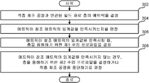
도 3의 프로그램은 빌드 메트릭 결정기(204)가 적층 제조 공정과 연관된 빌드 재료 층의 메트릭을 결정하는 것(블록 302)에서 시작한다. 품질 결정기(210)는 메트릭이 참조 메트릭의 임계값을 만족시키는지를 판정한다(블록 304). 메트릭이 참조 메트릭의 임계값을 만족시킬 때, 주입 프로파일 결정기(211)는 층을 융해하기 위한 제1 주입 프로파일을 결정한다(블록 306). 메트릭이 참조 메트릭의 임계값을 만족시키지 않는 경우, 주입 프로파일 결정기(211)는 층을 융해하기 위한 제2 주입 프로파일을 결정하거나 적층 제조 공정을 중단하기로 결정한다. 층이 제2 주입 프로파일에 기초하여 융해되고 제2 주입 프로파일의 결과가 예상과 다른 예에서, 업데이트기(209)는 제2 주입 프로파일을 제3 주입 프로파일로 업데이트할 수 있다.The program of FIG. 3 begins with build
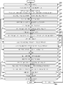
도 4의 프로그램은 빌드 제어기(106)가 데이터 저장 디바이스(120)로부터 빌드 계획(들)에 액세스하는 것(블록 350)으로 시작하고 빌드 재료 분포 프로파일 결정기(202)는 작업 영역(102) 상에 분포되는 빌드 재료를 식별한다(블록 352). 분포/증착되는 빌드 재료에 기초하여, 빌드 재료 분포 프로파일 결정기(202)는 원하는 및/또는 지시된 빌드 재료 경사도를 달성하는 방식으로 빌드 재료를 분포시키기 위한 빌드 재료 분포 프로파일을 선택한다(블록 354). 블록(356)에서, 빌드 재료 디스펜서 제어기(203)는 빌드 재료 디스펜서(110)가 선택된 빌드 재료 분포 프로파일에 따라 작업 영역(102) 상에 및/또는 이전에 증착되고/되거나 경화/융해된 빌드 재료 층의 맨 위에 빌드 재료를 분포시키게 한다(블록 356). 일부 예에서, 빌드 재료 디스펜서 제어기(203)는 원하는 빌드 재료 두께, 토포그래피 및/또는 경사도가 달성될 수 있도록 작업 영역(102)이 제2 기계장치(111)를 통해 이동하게 한다.The program in FIG. 4 begins with
빌드 메트릭 결정기(204)는 빌드 재료 층의 메트릭을 결정한다(블록 358). 일부 예에서, 빌드 메트릭 결정기(204)는 센서(113) 등으로부터 액세스된 데이터를 처리함으로써 빌드 재료의 최상층 및/또는 빌드 재료 층들 중 어느 하나의 메트릭(114)을 결정한다. 일부 예에서, 센서(113)는 본 명세서에 개시된 임의의 공정이 발생하는 동안 구성요소(110, 111, 112, 122, 124, 126, 132 등) 중 어느 하나의 빌드 및/또는 파라미터를 모니터링한다. 일부 예에서, 센서(113)는 본 명세서에 개시된 적층 제조 공정들 중 어느 하나가 발생한 후 구성요소(110, 111, 112, 122, 124, 126, 132 등) 중 임의의 하나의 빌드 및/또는 파라미터를 모니터링한다. 결정된 메트릭(114)에 기초하여, 모델러(206)는 모델(117)을 생성 및/또는 업데이트한다(블록 360). 일부 예에서, 모델(117)은 프린터(100)를 사용하여 형성되는 물체의 특성, 파라미터 등을 매핑 및/또는 연관시킨다. 추가적으로 또는 대안적으로, 일부 예에서, 모델(117)은 생성되는 물체의 층들 중 하나를 연관된 빌드 재료, 층의 두께, 층의 상면 토포그래피, 층의 하면 토포그래피를 포함하는 토포그래피 등과 매핑 및/또는 연관시킨다.The build
비교기(208)는 작업 영역(102) 상에 형성되는 물체의 층(들)의 메트릭(114)을 대응하는 참조 데이터(119)와 비교하고(블록 362), 품질 결정기(210)는 측정된/결정된 메트릭(114)이 참조 데이터(119)의 임계값 내에 있는지를 판정한다(블록 364). 형성되는 물체의 층(들)의 메트릭(114)이 임계값을 만족시키는 예에서, 모델러(206)는 층을 참조 데이터(119)를 만족시키는 것으로 연관시킨다(블록 365). 형성되는 물체의 층들의 메트릭(114)이 임계값을 만족시키지 않는 예에서, 품질 결정기(210)는 적층 제조 공정을 계속할지 여부를 판정한다(블록 366). 품질 결정기(210)가 적층 제조 공정을 계속하지 않기로 결정하면, 품질 결정기(210)는 경보를 생성하고(블록 368) 도 4의 프로그램은 종료된다. 일부 예에서, 경보는 유지보수를 수신하기 위한 프린터(100)의 구성요소에 대한 및/또는 생성되는 물체가 품질 임계값을 만족시키지 않는다는 세부사항을 포함한다. 예를 들어, 작업 영역(102) 상에 증착되는 빌드 재료의 경사도가 임계값을 만족시키지 않는 예에서, 경보는 블레이드, 롤러, 와이퍼 등과 같은 빌드 재료 디스펜서(110)의 구성요소를 교체하라는 표시를 포함할 수 있다.The
결정된 메트릭(114)이 참조 데이터(119)를 만족시키지 않고 품질 결정기(210)가 적층 제조 공정을 계속하기로 결정하면, 품질 결정기(210)는 빌드 재료가 재분포되어야하는지 여부를 판정한다(블록 370). 품질 결정기(210)가 빌드 재료가 재분배되어야 한다고 및/또는 층이 재형성되어야 한다고 결정하는 예에서, 빌드 재료 디스펜서 제어기(203)는 빌드 재료 디스펜서(110)가 빌드 재료를 재분포하게 하고, 빌드 재료의 두께를 변경하게 하며, 작업 영역(102) 상의 빌드 재료의 최상층의 토포그래피를 변경하게 한다(블록 372). 그 후, 프로그램은 빌드 메트릭 결정기(204)가 빌드 재료 층의 메트릭(114)을 결정하는 블록(308)으로 리턴한다(블록 358). 품질 결정기(210)가 빌드 재료가 재분포되어서는 안 되고 및/ 또는 층이 재형성되어서는 안 된다고 결정하는 예에서, 모델러(206)는 층을 참조 데이터(119)를 만족시키지 않는 것으로 연관시킨다(블록 374). If the
주입 프로파일 결정기(211)는 결정된 메트릭(114)에 기초하여 작업 영역(102) 상의 빌드 재료를 융해하기 위한 주입 프로파일을 결정하고(블록 376), 층은 융해된다(블록 378). 일부 예에서, 생성되는 물체의 층들을 융해 및/또는 결합시키기 위해, 작용제 디스펜서 제어기(214)는 작용제 디스펜서(124)가 결정된 주입 프로파일에 따라 층 상에 작용제를 분배하게 하고, 에너지원 제어기(216)는 에너지원(132)이 결정된 주입 프로파일에 따라 층 상에 에너지를 방출하게 한다. The
빌드 메트릭 결정기(204)는 빌드 재료 층의 메트릭(114)을 결정한다(블록 380). 일부 예에서, 융해된 후 층의 메트릭(114)은 층이 융해되기 전의 메트릭(114)과 상이하다. 일부 예에서, 작용제가 그 위에 증착된 후 층의 메트릭(114)은 작용제가 그 위에 증착되기 전의 메트릭(114)과 상이하다. 비교기(208)는 작업 영역(102) 상에 형성되는 물체의 층(들)의 메트릭(114)을 대응하는 참조 데이터(119)와 비교하고(블록 382), 품질 결정기(210)는 측정된/결정된 메트릭(114)이 참조 데이터(119)의 임계치 내에 있는지를 판정한다(블록 384).The build
메트릭(114)이 참조 데이터(119)의 임계값을 만족시키지 않는 예에서, 업데이트기(240)는 빌드 재료 분포 프로파일 및/또는 주입 프로파일을 업데이트할지 여부 판정한다(블록 386). 작업 영역(102) 상에 분포된 빌드 재료의 두께 및/또는 특성이 작업 영역(102) 상의 빌드 재료의 예상 두께 및/또는 특성과 여러 번(예를 들어, 연이어 3번) 및/또는 임의의 다른 이유로 다른 경우, 빌드 재료 분포 프로파일이 업데이트될 수 있다. 작업 영역(102) 상에 형성되는 층 및/또는 물체의 메트릭 및/또는 특성이 층 및/또는 물체의 예상 메트릭 및/또는 특성과 및/또는 임의의 다른 이유로 상이할 때 주입 프로파일이 업데이트될 수 있다. 업데이트기(240)가 빌드 재료 분포 프로파일 및/또는 주입 프로파일을 업데이트하기로 결정하면, 업데이트기(240)는 빌드 재료 분포 프로파일 및/또는 주입 프로파일을 업데이트한다(블록 388). 메트릭(114)이 임계값을 만족시키지 않는 경우, 품질 결정기(210)는 적층 제조 공정을 계속할지 여부를 판정한다(블록 390). 품질 결정기(210)가 적층 제조 공정을 계속하지 않기로 결정하면, 품질 결정기(210)는 경보를 생성하고(블록 368) 도 4의 프로그램은 종료된다.In the example where metric 114 does not meet the threshold of
품질 결정기(210)가 적층 제조 공정을 계속하기로 결정하는 경우 및/또는 메트릭(114)이 참조 메트릭의 임계값을 만족시키는 경우, 모델러(206)는 빌드 메트릭(114) 및 주입 프로파일을 형성된 관련 층과 연관 및/또는 매핑함으로써 모델(117)을 업데이트한다(블록 392). 블록(394)에서, 빌드 제어기(106)는 새로운 층을 생성할지 여부를 판정한다(블록 394). When the
도 5는 도 1의 빌드 제어기(106)를 구현하기 위한 도 3 및 도 4의 명령어를 실행할 수 있는 예시적인 프로세서 플랫폼(400)의 블록도이다. 프로세서 플랫폼(400)은 예를 들어, 서버, 개인용 컴퓨터, 모바일 디바이스(예를 들어, 휴대폰, 스마트폰, iPad™와 같은 태블릿), 개인 휴대정보 단말기(PDA), 인터넷 기기 또는 기타 유형의 컴퓨팅 디바이스일 수 있다.5 is a block diagram of an
도시된 예의 프로세서 플랫폼(400)은 프로세서(412)를 포함한다. 도시된 예의 프로세서(412)는 하드웨어이다. 예를 들어, 프로세서(412)는 임의의 원하는 제품군 또는 제조자로부터의 집적 회로, 로직 회로, 마이크로프로세서 및/또는 제어기에 의해 구현될 수 있다. 도시된 예에서, 프로세서(412)는 예시적인 빌드 재료 분포 프로파일 결정기(202), 예시적인 빌드 재료 디스펜서 제어기(203), 예시적인 빌드 메트릭 결정기(204), 예시적인 모델러(206), 예시적인 비교기(208), 업데이트기(209), 예시적인 품질 결정기(210), 예시적인 주입 프로파일 결정기(211), 예시적인 작업 영역 위치 제어기(212), 예시적인 디스펜서 제어기(214), 예시적인 에너지원 제어기(216) 및 예시적인 빌드 제어기(106)를 구현한다. The
도시된 예의 프로세서(412)는 로컬 메모리(413)(예를 들어, 캐시)를 포함한다. 도시된 예의 프로세서(412)는 버스(418)를 통해 휘발성 메모리(414) 및 비휘발성 메모리(416)를 포함하는 메인 메모리와 통신한다. 휘발성 메모리(414)는 SDRAM(Synchronous Dynamic Random Access Memory), DRAM(Dynamic Random Access Memory), RDRAM(RAMBUS Dynamic Random Access Memory) 및/또는 기타 유형의 랜덤 액세스 메모리 디바이스로 구현된다. 비휘발성 메모리(416)는 플래시 메모리 및/또는 임의의 다른 원하는 유형의 메모리 디바이스에 의해 구현될 수 있다. 메인 메모리(414, 416)로의 액세스는 메모리 제어기에 의해 제어된다. The
도시된 예의 프로세서 플랫폼(400)은 인터페이스 회로(420)도 포함한다. 인터페이스 회로(420)는 이더넷 인터페이스, 범용 직렬 버스(USB), 및/또는 PCI 익스프레스 인터페이스와 같은 임의의 유형의 인터페이스 표준에 의해 구현될 수 있다.The
도시된 예에서, 입력 디바이스(들)(422)는 인터페이스 회로(420)에 접속된다. 입력 디바이스(들)(422)는 사용자가 프로세서(412)에 데이터 및 커맨드를 입력하는 것을 허용한다. 입력 디바이스(들)는 예를 들어, 오디오 센서, 마이크로폰, 카메라(스틸 또는 비디오), 키보드, 버튼, 마우스, 터치스크린, 트랙 패드, 트랙볼, 아이소포인트 및/또는 음성 인식 시스템에 의해 구현될 수 있다.In the illustrated example, the input device (s) 422 is connected to the
출력 디바이스(들)(424)도 도시된 예의 인터페이스 회로(420)에 접속된다. 출력 디바이스들(424)은 예를 들어, 디스플레이 디바이스들(예를 들어, 발광 다이오드(LED), 유기 발광 다이오드(OLED), 액정 디스플레이, 음극선관 디스플레이(CRT), 터치스크린, 촉각 출력 디바이스, 프린터 및/또는 스피커)에 의해 구현될 수 있다. 그러므로, 도시된 예의 인터페이스 회로(420)는 전형적으로 그래픽 드라이버 카드, 그래픽 드라이버 칩 또는 그래픽 드라이버 프로세서를 포함한다. The output device (s) 424 is also connected to the illustrated
도시된 예의 인터페이스 회로(420)는 네트워크(426)(예를 들어, 이더넷 연결, DSL(digital subscriber line), 전화선, 동축 케이블, 셀룰러 전화 시스템 등)를 통해 외부 머신(예를 들어, 임의의 종류의 컴퓨팅 디바이스)과의 데이터 교환을 가능하게 하기 위해 송신기, 수신기, 송수신기, 모뎀 및/또는 네트워크 인터페이스 카드와 같은 통신 디바이스도 포함한다. The
도시된 예의 프로세서 플랫폼(400)은 소프트웨어 및/또는 데이터를 저장하는 대용량 저장 디바이스(들)(428)도 포함한다. 그러한 대용량 저장 디바이스(428)의 예는 플로피 디스크 드라이브, 하드 드라이브 디스크, 콤팩트 디스크 드라이브, 블루레이 디스크 드라이브, RAID 시스템, 및 디지털 다기능 디스크(DVD) 드라이브를 포함한다. 도시된 예에서, 대용량 저장 디바이스(들)(428)는 데이터 저장 디바이스(120)를 구현한다. The
도 3 및 도 4의 코딩된 명령어(432)는 대용량 저장 디바이스(428), 휘발성 메모리(414), 비휘발성 메모리(416) 및/또는 CD 또는 DVD와 같은 이동식인 유형의 컴퓨터 판독가능 저장 매체에 저장될 수 있다. The coded
전술한 것으로부터, 앞에서 개시된 방법, 장치 및 제조 물품은 형성되는 물체 및/또는 그 물체를 구성하는 층의 메트릭에 기초하여 모델을 생성하는 3차원(3D) 프린터에 관한 것임을 이해할 것이다. 본 발명의 교시와 관련하여 생성된 모델을 사용하여, 추가적인 품질 절차(예를 들어, 오프라인 품질 절차 등)가 발생하지 않고도 품질 임계값을 만족시키도록 생성된 물체 및/또는 부품이 결정될 수 있다.From the foregoing, it will be understood that the methods, devices, and articles of manufacture disclosed above relate to a three-dimensional (3D) printer that generates a model based on the metrics of the object being formed and / or the layers that make up the object. Using the model generated in connection with the teachings of the present invention, objects and / or parts created to satisfy the quality threshold can be determined without requiring additional quality procedures (eg, offline quality procedures, etc.).
일부 예에서, 본 명세서에 개시된 예시적인 프린터를 사용하여 물체(들)를 생성할 때, 증착되는 층들의 불일치는 생성되는 물체(들)의 품질을 변경할 수 있다. 임계값을 만족시키지 않는 품질 레벨을 갖는 물체가 생성되는 것을 방지하고/하거나 제조 환경에서 생성되는 폐기 부품(예를 들어, 품질 임계값을 만족시키지 않는 부품)을 최소화하기 위해, 본 명세서에 개시된 예는 작업 영역 및/또는 그 위에 증착된 빌드 재료를 모니터링하고, 생성된 물체의 층이 참조 데이터의 임계값을 만족시킬 수 있도록 빌드 재료의 두께 및/또는 토포그래피를 동적으로 조정한다. In some examples, when creating the object (s) using the example printer disclosed herein, the mismatch of the deposited layers can change the quality of the resulting object (s). Examples disclosed herein to prevent the creation of objects with a quality level that does not satisfy the threshold and / or to minimize waste components (eg, components that do not meet the quality threshold) generated in the manufacturing environment Monitors the work area and / or the build material deposited thereon, and dynamically adjusts the thickness and / or topography of the build material so that the layer of generated object meets the threshold of reference data.
부가적으로 또는 대안적으로, 임계값을 만족시키지 않는 품질 레벨을 갖는 물체가 생성되는 것을 방지하고/하거나 제조 환경에서 생성되는 폐기 부품(예를 들어, 품질 임계값을 만족시키지 않는 부품)을 최소화하기 위해, 본 명세서에 개시된 예는 작업 영역 및/또는 그 위에 증착된 빌드 재료를 모니터링하고 결정된 메트릭과 연관되는 주입 프로파일을 선택한다. 예를 들어, 제1 주입 프로파일은 제1 두께 및/또는 다른 특성을 갖는 제1 빌드 재료 층을 위해 선택될 수 있고, 제2 주입 프로파일은 제2 두께 및/또는 다른 특성을 갖는 제2 빌드 재료 층을 위해 선택될 수 있다. 제1 두께가 제2 두께보다 큰 예에서, 제1 주입 프로파일은 제1 층을 융해하기 위해 더 많은 작용제 및/또는 더 많은 에너지가 인가되게 할 수 있고, 제2 주입 프로파일은 제2 층을 융해하기 위해 더 적은 작용제 및/또는 더 적은 에너지가 인가되게 할 수 있다. 물론, 임의의 양의 작용제 및/또는 임의의 양의 에너지가 본 명세서의 교시에 따라 생성된 물체가 품질 임계값을 만족시킬 수 있게 하는 데 사용될 수 있다.Additionally or alternatively, it prevents the creation of objects with a quality level that does not meet the threshold and / or minimizes waste parts (eg, parts that do not meet the quality threshold) produced in the manufacturing environment. To do so, the examples disclosed herein monitor the work area and / or build material deposited thereon and select the injection profile associated with the determined metric. For example, the first injection profile can be selected for a first build material layer having a first thickness and / or other properties, and the second injection profile is a second build material having a second thickness and / or other properties. Can be chosen for layers. In an example where the first thickness is greater than the second thickness, the first injection profile can cause more agent and / or more energy to be applied to melt the first layer, and the second injection profile melts the second layer In order to do so, less agent and / or less energy can be applied. Of course, any amount of agent and / or any amount of energy can be used to enable an object produced according to the teachings herein to meet a quality threshold.
예 1Example 1
예시적인 프린터는 빌드 재료 층이 증착되는 작업 영역과, 층의 메트릭에 액세스하고, 메트릭에 기초하여 복수의 주입 프로파일 중에서 층을 융해하기 위한 주입 프로파일을 선택하는 빌드 제어기와, 노즐을 포함하는 작용제 분포기를 포함하며, 작용제 분포기는 노즐이 주입 프로파일에 기초하여 층 상에 작용제를 분포시키게 한다.An exemplary printer includes a working area in which a layer of build material is deposited, a build controller to access a metric of the layer, and select an injection profile to melt the layer from among the plurality of injection profiles based on the metric, and agent distribution including nozzles Group, and the agent distributor causes the nozzle to distribute the agent on the layer based on the injection profile.
예 2Example 2
예 1 또는 다른 예에서, 프린터는 주입 프로파일에 기초하여 층 상으로 에너지를 방출하는 에너지원을 포함한다.In Example 1 or another example, the printer includes an energy source that emits energy onto the layer based on the injection profile.
예 3Example 3
예 1, 2 또는 다른 예에서, 메트릭은 제1 메트릭이고, 층은 제1층이며, 프린터는 빌드 재료 디스펜서를 더 포함하고, 제1 메트릭이 임계값을 만족시키지 않는 것에 응답하여, 빌드 제어기는 빌드 재료 디스펜서가 제1층을 변경하게 한다.In Examples 1, 2, or another example, the metric is the first metric, the layer is the first layer, the printer further comprises a build material dispenser, and in response to the first metric not meeting the threshold, the build controller is The build material dispenser causes the first layer to change.
예 4Example 4
예 3 또는 다른 예에서, 빌드 제어기는 제2층의 제2 메트릭에 액세스하고, 제2 메트릭이 참조 메트릭을 만족시키는지 여부를 판정하기 위해 제2 메트릭을 처리한다.In Example 3 or another example, the build controller accesses the second metric in the second layer and processes the second metric to determine whether the second metric satisfies the reference metric.
예 5Example 5
예 4 또는 다른 예에서, 주입 프로파일은 제1 주입 프로파일이며, 제2 메트릭이 참조 메트릭을 만족시키지 않는 것에 응답하여, 빌드 제어기는 제2 메트릭에 기초하여 복수의 주입 프로파일 중에서 제2층을 융해하기 위한 제2 주입 프로파일을 선택하고, 제2 메트릭이 참조 메트릭을 만족시키는 것에 응답하여, 빌드 제어기는 제2 메트릭에 기초하여 복수의 주입 프로파일 중에서 제2층을 융해하기 위한 제3 주입 프로파일을 선택한다.In Example 4 or another example, the injection profile is the first injection profile, and in response to the second metric not satisfying the reference metric, the build controller melts the second layer among the plurality of injection profiles based on the second metric. Select a second injection profile for, and in response to the second metric satisfying the reference metric, the build controller selects a third injection profile for melting the second layer among the plurality of injection profiles based on the second metric. .
예 6Example 6
예 3, 4 또는 다른 예에서, 빌드 제어기는 제2 메트릭에 기초하여 복수의 주입 프로파일 중에서 제2층을 융해하기 위한 제2 주입 프로파일을 선택한다.In Examples 3, 4, or another example, the build controller selects a second injection profile for melting the second layer from the plurality of injection profiles based on the second metric.
예 7Example 7
예 6 또는 다른 예에서, 빌드 제어기는 제1층 및 제2층을 나타내는 모델을 생성하는 모델러를 포함하고, 모델은 제1 메트릭 및 제2 메트릭을 포함한다.In Example 6 or another example, the build controller includes a modeler that generates models representing the first and second layers, and the model includes a first metric and a second metric.
예 8Example 8
예 1, 2, 3, 4, 5, 6, 7 또는 다른 예에서, 빌드 제어기는 주입 프로파일의 결과가 예상과 다를 때 주입 프로파일을 업데이트하는 업데이트기를 포함한다.In Examples 1, 2, 3, 4, 5, 6, 7 or other examples, the build controller includes an updater that updates the injection profile when the results of the injection profile are different than expected.
예 9Example 9
예시적인 장치는 적층 제조 공정과 연관된 빌드 재료 층의 메트릭을 결정하는 빌드 메트릭 결정기와, 메트릭이 참조 메트릭의 임계값을 만족시키는지 여부를 판정하는 품질 결정기와, 주입 프로파일 결정기를 포함하되, 메트릭이 참조 메트릭의 임계값을 만족시킬 때, 주입 프로파일 결정기는 층을 융해하기 위한 제1 주입 프로파일을 결정하고, 메트릭이 참조 메트릭의 임계값을 만족시키지 않을 때, 주입 프로파일 결정기는 층을 융해하기 위한 제2 주입 프로파일을 결정하거나 적층 제조 공정을 중단시키도록 결정한다.Exemplary devices include a build metric determiner that determines the metric of the build material layer associated with the additive manufacturing process, a quality determiner that determines whether the metric satisfies a threshold of a reference metric, and an injection profile determiner, wherein the metric is When the threshold of the reference metric is satisfied, the injection profile determiner determines the first injection profile to melt the layer, and when the metric does not satisfy the threshold of the reference metric, the injection profile determiner is used to melt the layer. 2 Determine the injection profile or decide to stop the additive manufacturing process.
예 10Example 10
예 9 또는 다른 예에서, 제1 주입 프로파일은 제2 주입 프로파일과 상이하다.In Example 9 or another example, the first injection profile is different from the second injection profile.
예 11Example 11
예 9, 10 또는 다른 예에서, 제1 주입 프로파일 또는 제2 주입 프로파일에 기초하여 층 상에 작용제가 분배되게 하는 작용제 디스펜서 제어기를 더 포함한다.In Examples 9, 10, or another example, further comprising an agent dispenser controller that causes the agent to be dispensed on the layer based on the first injection profile or the second injection profile.
예 12Example 12
예 9, 10, 11 또는 다른 예에서, 제1 주입 프로파일 또는 제2 주입 프로파일에 기초하여 층 상으로 에너지가 방출되게 하는 에너지원 제어기를 더 포함한다.In Examples 9, 10, 11 or other examples, further comprising an energy source controller that allows energy to be released into the layer based on the first injection profile or the second injection profile.
예 13Example 13
예시적인 방법은 적어도 하나의 프로세서를 이용하여 명령어를 실행함으로써, 적층 제조 공정과 연관된 빌드 재료 층의 메트릭을 결정하는 단계와, 적어도 하나의 프로세서를 이용하여 명령어를 실행함으로써, 메트릭이 참조 메트릭의 임계값을 만족시키는지 여부를 판정하는 단계와, 메트릭이 참조 메트릭의 임계값을 만족시킬 때, 적어도 하나의 프로세서를 이용하여 명령어를 실행함으로써, 층을 융해하기 위한 제1 주입 프로파일을 결정하는 단계와, 메트릭이 참조 메트릭의 임계값을 만족시키지 않을 때, 적어도 하나의 프로세서를 이용하여 명령어를 실행함으로써, 층을 융해하기 위한 제2 주입 프로파일을 결정하거나 적층 제조 공정을 중단시키도록 결정하는 단계를 포함한다.An exemplary method includes determining an metric of a build material layer associated with an additive manufacturing process by executing an instruction using at least one processor, and executing the instruction using at least one processor, such that the metric is the threshold of the reference metric. Determining whether a value is satisfied, and when the metric satisfies a threshold of the reference metric, executing instructions using at least one processor to determine a first injection profile for melting the layer; , When the metric does not satisfy the threshold value of the reference metric, by executing instructions using at least one processor, determining a second injection profile to melt the layer or deciding to stop the additive manufacturing process. do.
예 14Example 14
예 13 또는 다른 예에서, 제2 주입 프로파일에 기초하여 층을 융해하는 단계와, 제2 주입 프로파일의 결과가 예상과 다른 경우 제2 주입 프로파일을 제3 주입 프로파일로 업데이트하는 단계를 더 포함한다.In Example 13 or another example, further comprising melting the layer based on the second injection profile and updating the second injection profile to the third injection profile when the result of the second injection profile is different than expected.
예 15Example 15
예 13, 14 또는 다른 예에서, 제1 주입 프로파일 또는 제2 주입 프로파일에 기초하여 층 상에 작용제가 분배되게 하는 단계와, 제1 주입 프로파일 또는 제2 주입 프로파일에 기초하여 층 상으로 에너지가 방출되게 하는 단계를 더 포함한다.In Examples 13, 14 or another example, causing the agent to be dispensed on the layer based on the first injection profile or the second injection profile, and energy is released into the layer based on the first injection profile or the second injection profile It further comprises a step of making.
예 16Example 16
예시적인 프린터는 작업 영역 상의 층의 메트릭에 액세스하고, 메트릭에 기초하여 복수의 주입 프로파일 중에서 층을 융해하기 위한 주입 프로파일을 선택하는 빌드 제어기를 포함한다.The exemplary printer includes a build controller that accesses a metric of the layer on the work area and selects an injection profile to melt the layer from among multiple injection profiles based on the metric.
예 17Example 17
예 16 또는 다른 예에서, 노즐을 포함하는 작용제 분포기를 더 포함하며, 작용제 분포기는 노즐이 주입 프로파일에 기초하여 층 상에 작용제를 분포시키게 한다.In Example 16 or another example, further comprising an agent distributor comprising a nozzle, the agent distributor causing the nozzle to distribute the agent on the layer based on the injection profile.
예 18Example 18
예 16, 17 또는 다른 예에서, 주입 프로파일에 기초하여 층 상으로 에너지를 방출하는 에너지원을 더 포함한다.In Examples 16, 17 or another example, further comprising an energy source that emits energy onto the layer based on the implant profile.
예 19Example 19
예 16, 17, 18 또는 다른 예에서, 메트릭은 제1 메트릭이고, 층은 제1층이며, 프린터는 빌드 재료 디스펜서를 더 포함하고, 제1 메트릭이 임계값을 만족시키지 않는 것에 응답하여, 빌드 제어기는 빌드 재료 디스펜서가 제1층의 특성을 변경하게 한다.In Examples 16, 17, 18 or another example, the metric is the first metric, the layer is the first layer, the printer further comprises a build material dispenser, and in response to the first metric not meeting the threshold, build The controller allows the build material dispenser to change the properties of the first layer.
예 20Example 20
예 19 또는 다른 예에서, 빌드 제어기는 제2층의 제2 메트릭에 액세스하고, 제2 메트릭이 참조 메트릭을 만족시키는지 여부를 판정하기 위해 제2 메트릭을 처리한다.In Example 19 or another example, the build controller accesses the second metric of the second layer and processes the second metric to determine whether the second metric satisfies the reference metric.
예 21Example 21
예 20 또는 다른 예에서, 주입 프로파일은 제1 주입 프로파일이며, 제2 메트릭이 참조 메트릭을 만족시키지 않는 것에 응답하여, 빌드 제어기는 제2 메트릭에 기초하여 복수의 주입 프로파일 중에서 제2층을 융해하기 위한 제2 주입 프로파일을 선택하고, 제2 메트릭이 참조 메트릭을 만족시키는 것에 응답하여, 빌드 제어기는 제2 메트릭에 기초하여 복수의 주입 프로파일 중에서 제2층을 융해하기 위한 제3 주입 프로파일을 선택한다.In Example 20 or another example, the injection profile is a first injection profile, and in response to the second metric not satisfying the reference metric, the build controller melts the second layer among the plurality of injection profiles based on the second metric. Select a second injection profile for, and in response to the second metric satisfying the reference metric, the build controller selects a third injection profile for melting the second layer among the plurality of injection profiles based on the second metric. .
예 22Example 22
예 21 또는 다른 예에서, 빌드 제어기는 제2 메트릭에 기초하여 복수의 주입 프로파일 중에서 제2층을 융해하기 위한 제2 주입 프로파일을 선택한다.In Example 21 or another example, the build controller selects a second injection profile for melting the second layer from the plurality of injection profiles based on the second metric.
예 23Example 23
예 22 또는 다른 예에서, 빌드 제어기는 제1층 및 제2층을 나타내는 모델을 생성하는 모델러를 포함하고, 모델은 제1 메트릭 및 제2 메트릭을 포함한다.In Example 22 or another example, the build controller includes a modeler that generates models representing the first and second layers, and the model includes a first metric and a second metric.
예 24Example 24
예 16, 17, 18, 19, 20, 21, 22, 23 또는 다른 예에서, 빌드 제어기는 주입 프로파일의 결과가 예상과 다를 때 주입 프로파일을 업데이트하는 업데이트기를 포함한다.In Examples 16, 17, 18, 19, 20, 21, 22, 23 or other examples, the build controller includes an updater that updates the injection profile when the results of the injection profile are different than expected.
소정의 예시적인 방법, 장치 및 제조 물품이 본 명세서에 개시되었지만, 본 특허의 범위는 이에 제한되지 않는다. 반대로, 본 특허는 본 특허의 청구범위의 범주 내에 명백히 있는 모든 방법, 장치 및 제조 물품을 포함한다.Although certain exemplary methods, devices, and articles of manufacture have been disclosed herein, the scope of this patent is not limited thereto. Conversely, this patent includes all methods, devices, and articles of manufacture that are clearly within the scope of the claims of this patent.
Claims (15)
작업 영역 상의 층의 메트릭에 액세스하고, 상기 메트릭에 기초하여 복수의 주입 프로파일(dosing profile) 중에서 상기 층을 융해하기 위한 주입 프로파일을 선택하는 빌드 제어기를 포함하는
프린터.
As a printer,
And a build controller that accesses a metric of the layer on the work area and selects an injection profile for melting the layer among a plurality of dosing profiles based on the metric.
printer.
노즐을 포함하는 작용제 분포기를 더 포함하되,
상기 작용제 분포기는 상기 노즐이 상기 주입 프로파일에 기초하여 상기 층 상에 작용제를 분포시키게 하는
프린터.
According to claim 1,
Further comprising an agent distributor comprising a nozzle,
The agent distributor causes the nozzle to distribute the agent on the layer based on the injection profile.
printer.
상기 주입 프로파일에 기초하여 상기 층 상으로 에너지를 방출하는 에너지원을 더 포함하는
프린터.
According to claim 1,
Further comprising an energy source that emits energy onto the layer based on the injection profile
printer.
상기 메트릭은 제1 메트릭이고, 상기 층은 제1층이며, 상기 프린터는 빌드 재료 디스펜서를 더 포함하고,
상기 제1 메트릭이 임계값을 만족시키지 않는 것에 응답하여, 상기 빌드 제어기는 상기 빌드 재료 디스펜서가 상기 제1층의 특성을 변경하게 하는
프린터.
According to claim 1,
The metric is the first metric, the layer is the first layer, and the printer further comprises a build material dispenser,
In response to the first metric not meeting a threshold, the build controller causes the build material dispenser to change the properties of the first layer.
printer.
상기 빌드 제어기는 제2층의 제2 메트릭에 액세스하고, 상기 제2 메트릭이 참조 메트릭을 만족시키는지 여부를 판정하기 위해 상기 제2 메트릭을 처리하는
프린터.
According to claim 4,
The build controller accesses the second metric of the second layer and processes the second metric to determine whether the second metric satisfies the reference metric.
printer.
상기 주입 프로파일은 제1 주입 프로파일이며,
상기 제2 메트릭이 상기 참조 메트릭을 만족시키지 않는 것에 응답하여, 상기 빌드 제어기는 상기 제2 메트릭에 기초하여 상기 복수의 주입 프로파일 중에서 상기 제2층을 융해하기 위한 제2 주입 프로파일을 선택하고, 상기 제2 메트릭이 상기 참조 메트릭을 만족시키는 것에 응답하여, 상기 빌드 제어기는 상기 제2 메트릭에 기초하여 상기 복수의 주입 프로파일 중에서 상기 제2층을 융해하기 위한 제3 주입 프로파일을 선택하는
프린터.
The method of claim 5,
The injection profile is a first injection profile,
In response to the second metric not satisfying the reference metric, the build controller selects a second injection profile for melting the second layer from among the plurality of injection profiles based on the second metric, and the In response to a second metric satisfying the reference metric, the build controller selects a third injection profile to melt the second layer from among the plurality of injection profiles based on the second metric.
printer.
상기 빌드 제어기는 상기 제2 메트릭에 기초하여 상기 복수의 주입 프로파일 중에서 상기 제2층을 융해하기 위한 제2 주입 프로파일을 선택하는
프린터.
The method of claim 5,
The build controller selects a second injection profile for melting the second layer from among the plurality of injection profiles based on the second metric.
printer.
상기 빌드 제어기는 상기 제1층 및 상기 제2층을 나타내는 모델을 생성하는 모델러를 포함하고,
상기 모델은 상기 제1 메트릭 및 상기 제2 메트릭을 포함하는
프린터.
The method of claim 7,
The build controller includes a modeler generating models representing the first layer and the second layer,
The model includes the first metric and the second metric
printer.
상기 빌드 제어기는 상기 주입 프로파일의 결과가 예상과 다를 때 상기 주입 프로파일을 업데이트하는 업데이트기를 포함하는
프린터.
According to claim 1,
The build controller includes an updater that updates the injection profile when the result of the injection profile is different than expected
printer.
적층 제조 공정과 연관된 빌드 재료 층의 메트릭을 결정하는 빌드 메트릭 결정기와,
상기 메트릭이 참조 메트릭의 임계값을 만족시키는지 여부를 판정하는 품질 결정기와,
주입 프로파일 결정기를 포함하되,
상기 메트릭이 상기 참조 메트릭의 임계값을 만족시킬 때, 상기 주입 프로파일 결정기는 상기 층을 융해하기 위한 제1 주입 프로파일을 결정하고, 상기 메트릭이 상기 참조 메트릭의 임계값을 만족시키지 않을 때, 상기 주입 프로파일 결정기는 상기 층을 융해하기 위한 제2 주입 프로파일을 결정하거나 상기 적층 제조 공정을 중단시키도록 결정하는
장치.
As a device,
A build metric determiner that determines the metric of the build material layer associated with the additive manufacturing process,
A quality determiner that determines whether the metric satisfies a threshold value of a reference metric,
Include an injection profile determiner,
When the metric satisfies the threshold of the reference metric, the injection profile determiner determines a first injection profile for melting the layer, and when the metric does not satisfy the threshold of the reference metric, the injection The profile determiner determines a second injection profile for melting the layer or decides to stop the additive manufacturing process.
Device.
상기 제1 주입 프로파일 또는 상기 제2 주입 프로파일에 기초하여 상기 층 상에 작용제가 분배되게 하는 작용제 디스펜서 제어기를 더 포함하는
장치.
The method of claim 10,
And an agent dispenser controller that allows agents to be dispensed on the layer based on the first injection profile or the second injection profile.
Device.
상기 제1 주입 프로파일 또는 상기 제2 주입 프로파일에 기초하여 상기 층 상으로 에너지가 방출되게 하는 에너지원 제어기를 더 포함하는
장치.
The method of claim 10,
And an energy source controller that allows energy to be released onto the layer based on the first injection profile or the second injection profile.
Device.
상기 적어도 하나의 프로세서를 이용하여 명령어를 실행함으로써, 상기 메트릭이 참조 메트릭의 임계값을 만족시키는지 여부를 판정하는 단계와,
상기 메트릭이 상기 참조 메트릭의 임계값을 만족시킬 때, 상기 적어도 하나의 프로세서를 이용하여 명령어를 실행함으로써, 상기 층을 융해하기 위한 제1 주입 프로파일을 결정하는 단계와,
상기 메트릭이 상기 참조 메트릭의 임계값을 만족시키지 않을 때, 상기 적어도 하나의 프로세서를 이용하여 명령어를 실행함으로써, 상기 층을 융해하기 위한 제2 주입 프로파일을 결정하거나 상기 적층 제조 공정을 중단시키도록 결정하는 단계를 포함하는
방법.
Determining a metric of a layer of build material associated with the additive manufacturing process by executing instructions using at least one processor,
Determining whether the metric satisfies a threshold value of a reference metric by executing an instruction using the at least one processor,
When the metric satisfies the threshold of the reference metric, determining an first injection profile for melting the layer by executing instructions using the at least one processor;
When the metric does not satisfy the threshold value of the reference metric, it is determined to execute a command using the at least one processor to determine a second injection profile for melting the layer or to stop the additive manufacturing process. Which includes the steps of
Way.
상기 제2 주입 프로파일에 기초하여 상기 층을 융해하는 단계와, 상기 제2 주입 프로파일의 결과가 예상과 다른 경우 상기 제2 주입 프로파일을 제3 주입 프로파일로 업데이트하는 단계를 더 포함하는
방법.
The method of claim 13,
Melting the layer based on the second injection profile, and updating the second injection profile to a third injection profile when the result of the second injection profile is different than expected.
Way.
상기 제1 주입 프로파일 또는 상기 제2 주입 프로파일에 기초하여 상기 층 상에 작용제가 분배되게 하는 단계와, 상기 제1 주입 프로파일 또는 상기 제2 주입 프로파일에 기초하여 상기 층 상으로 에너지가 방출되게 하는 단계를 더 포함하는
방법.The method of claim 13,
Causing an agent to be distributed on the layer based on the first injection profile or the second injection profile, and allowing energy to be released onto the layer based on the first injection profile or the second injection profile Containing more
Way.
Applications Claiming Priority (1)
| Application Number | Priority Date | Filing Date | Title |
|---|---|---|---|
| PCT/US2017/049750 WO2019045744A1 (en) | 2017-08-31 | 2017-08-31 | Printers |
Publications (1)
| Publication Number | Publication Date |
|---|---|
| KR20200030103A true KR20200030103A (en) | 2020-03-19 |
Family
ID=65527468
Family Applications (1)
| Application Number | Title | Priority Date | Filing Date |
|---|---|---|---|
| KR1020207004592A KR20200030103A (en) | 2017-08-31 | 2017-08-31 | printer |
Country Status (7)
| Country | Link |
|---|---|
| US (1) | US11801638B2 (en) |
| EP (1) | EP3642019A4 (en) |
| JP (1) | JP6941735B2 (en) |
| KR (1) | KR20200030103A (en) |
| CN (1) | CN111051046B (en) |
| BR (1) | BR112020003302A2 (en) |
| WO (1) | WO2019045744A1 (en) |
Families Citing this family (5)
| Publication number | Priority date | Publication date | Assignee | Title |
|---|---|---|---|---|
| US11376796B2 (en) * | 2018-07-23 | 2022-07-05 | Hewlett-Packard Development Company, L.P. | Adapting printing parameters during additive manufacturing processes |
| EP3599080A1 (en) * | 2018-07-27 | 2020-01-29 | Concept Laser GmbH | Apparatus for additively manufacturing three-dimensional objects |
| US20200238603A1 (en) * | 2019-01-25 | 2020-07-30 | Continuous Composites Inc. | System for additively manufacturing composite structure |
| US20230186524A1 (en) * | 2021-12-15 | 2023-06-15 | Hewlett-Packard Development Company, L.P. | Object model encodings |
| US11541606B1 (en) * | 2021-12-23 | 2023-01-03 | Inkbit, LLC | Object model encoding for additive fabrication |
Family Cites Families (24)
| Publication number | Priority date | Publication date | Assignee | Title |
|---|---|---|---|---|
| US5460758A (en) | 1990-12-21 | 1995-10-24 | Eos Gmbh Electro Optical Systems | Method and apparatus for production of a three-dimensional object |
| IT1259166B (en) | 1992-10-09 | 1996-03-11 | Padana Monteverde Mecc Mpm | TRANSMISSION WITH INTEGRATED BRAKE PARTICULARLY FOR VEHICLES |
| US6780368B2 (en) | 2001-04-10 | 2004-08-24 | Nanotek Instruments, Inc. | Layer manufacturing of a multi-material or multi-color 3-D object using electrostatic imaging and lamination |
| AU2003261497B2 (en) * | 2002-11-08 | 2009-02-26 | Howmedica Osteonics Corp. | Laser-produced porous surface |
| DE102007056984A1 (en) * | 2007-11-27 | 2009-05-28 | Eos Gmbh Electro Optical Systems | Method for producing a three-dimensional object by means of laser sintering |
| US10183329B2 (en) | 2013-07-19 | 2019-01-22 | The Boeing Company | Quality control of additive manufactured parts |
| US9855698B2 (en) | 2013-08-07 | 2018-01-02 | Massachusetts Institute Of Technology | Automatic process control of additive manufacturing device |
| US20150177158A1 (en) | 2013-12-13 | 2015-06-25 | General Electric Company | Operational performance assessment of additive manufacturing |
| US9724876B2 (en) | 2013-12-13 | 2017-08-08 | General Electric Company | Operational performance assessment of additive manufacturing |
| WO2015106844A1 (en) * | 2014-01-16 | 2015-07-23 | Hewlett-Packard Development Company L.P. | Build material profile |
| EP3126122B1 (en) * | 2014-03-31 | 2019-09-04 | Hewlett-Packard Development Company, L.P. | Generating three-dimensional objects |
| CN105014958B (en) * | 2014-04-15 | 2017-08-04 | 上海智位机器人股份有限公司 | 3D printer and its method for automatically leveling |
| WO2015170330A1 (en) | 2014-05-08 | 2015-11-12 | Stratasys Ltd. | Method and apparatus for 3d printing by selective sintering |
| SE1450569A1 (en) | 2014-05-14 | 2015-11-03 | Katarina Gustafsson | A method and apparatus for geometric verification in the additive manufacture of three-dimensional objects |
| CN103978690B (en) * | 2014-05-28 | 2016-05-11 | 山东大学 | A kind of internal structure of body optimization method of printing towards 3D |
| CN104057611B (en) * | 2014-06-05 | 2016-03-23 | 浙江大学 | A kind of 3D optimized based on scan line inclination angle prints fill path generation method |
| US20160098824A1 (en) * | 2014-10-03 | 2016-04-07 | Tyco Electronics Corporation | Three dimensional printing inspection apparatus and method |
| US10052823B2 (en) * | 2014-10-08 | 2018-08-21 | Xerox Corporation | System and method for test pattern formation during three-dimensional object printing |
| JP6421562B2 (en) * | 2014-11-25 | 2018-11-14 | セイコーエプソン株式会社 | Three-dimensional structure manufacturing method and three-dimensional structure manufacturing apparatus |
| WO2016084367A1 (en) * | 2014-11-28 | 2016-06-02 | Canon Kabushiki Kaisha | Three-dimensional shaping apparatus and three-dimensional shaped article manufacturing method |
| KR102223993B1 (en) * | 2015-04-30 | 2021-03-05 | 휴렛-팩커드 디벨롭먼트 컴퍼니, 엘.피. | Printing multi-structured 3d object |
| TWI567364B (en) * | 2015-09-08 | 2017-01-21 | 財團法人工業技術研究院 | Structured light generating apparatus, measuring system and method thereof |
| US10843452B2 (en) * | 2016-12-01 | 2020-11-24 | The Boeing Company | Systems and methods for cure control of additive manufacturing |
| WO2019040948A1 (en) * | 2017-08-25 | 2019-02-28 | Massachusetts Institute Of Technology | Sensing and control of additive manufacturing processes |
-
2017
- 2017-08-31 US US16/608,416 patent/US11801638B2/en active Active
- 2017-08-31 WO PCT/US2017/049750 patent/WO2019045744A1/en unknown
- 2017-08-31 JP JP2020531419A patent/JP6941735B2/en active Active
- 2017-08-31 EP EP17923634.4A patent/EP3642019A4/en active Pending
- 2017-08-31 KR KR1020207004592A patent/KR20200030103A/en not_active IP Right Cessation
- 2017-08-31 BR BR112020003302-2A patent/BR112020003302A2/en unknown
- 2017-08-31 CN CN201780094337.5A patent/CN111051046B/en active Active
Also Published As
| Publication number | Publication date |
|---|---|
| JP2020531331A (en) | 2020-11-05 |
| EP3642019A4 (en) | 2021-01-27 |
| BR112020003302A2 (en) | 2020-08-25 |
| US11801638B2 (en) | 2023-10-31 |
| EP3642019A1 (en) | 2020-04-29 |
| WO2019045744A1 (en) | 2019-03-07 |
| US20200189200A1 (en) | 2020-06-18 |
| JP6941735B2 (en) | 2021-09-29 |
| CN111051046B (en) | 2022-02-15 |
| CN111051046A (en) | 2020-04-21 |
Similar Documents
| Publication | Publication Date | Title |
|---|---|---|
| KR20200030103A (en) | printer | |
| US10831181B2 (en) | Addition controller, addition control method, and program | |
| US11639032B2 (en) | Accuracy improvement and surface finishing using fusing agent and detailing agent | |
| US11409261B2 (en) | Predicting distributions of values of layers for three-dimensional printing | |
| JP6454035B2 (en) | Method and apparatus for printing three-dimensional (3D) objects | |
| TWI795542B (en) | Generating adapted control instructions for a 3d printing process | |
| EP3710187B1 (en) | Methods and systems for repairing powder containment structures | |
| TW202308833A (en) | Systems, methods, and media for artificial intelligence feedback control in additive manufacturing | |
| EP3426466B1 (en) | Predicting quality of a 3d object part | |
| US9524357B1 (en) | Systems, methods and apparatus for generating and modifying support structures | |
| KR101982831B1 (en) | Control method of printing temperature and device thereof | |
| JP2020001302A (en) | Molding prediction system, molding prediction display system, information processor and program | |
| CN110032343A (en) | For best orientation object with the method and apparatus for processing automatically | |
| JP2018034494A (en) | Platform movement type 3d printing method | |
| CN108274735B (en) | Layer-cutting printing method for multicolor 3D object | |
| US11396183B2 (en) | Printers and associated printer maintenance | |
| US11776072B2 (en) | Machine learning method, information processing device, computer program product, and additive manufacturing monitoring system | |
| US11884022B2 (en) | Method and system for enhancing the lifetime of printing heads used in additive manufacturing | |
| US20230032439A1 (en) | Generation of an object model for three dimensional printers | |
| US20190168453A1 (en) | Printer warming device control | |
| WO2018194625A1 (en) | Printers | |
| JP7284083B2 (en) | Modeling device and clear ink replenishment amount input method | |
| US20240051219A1 (en) | Systems and methods of offset surface deposition in additive fabrication | |
| US20230280717A1 (en) | Heat-aware toolpath generation for 3d printing of physical parts | |
| US20210362243A1 (en) | Three-dimensional printing |
Legal Events
| Date | Code | Title | Description |
|---|---|---|---|
| E902 | Notification of reason for refusal | ||
| AMND | Amendment | ||
| E601 | Decision to refuse application | ||
| X091 | Application refused [patent] | ||
| AMND | Amendment | ||
| X601 | Decision of rejection after re-examination |