KR20200028406A - Method and apparatus for optically measuring the surface of a measurement object - Google Patents
Method and apparatus for optically measuring the surface of a measurement object Download PDFInfo
- Publication number
- KR20200028406A KR20200028406A KR1020207003010A KR20207003010A KR20200028406A KR 20200028406 A KR20200028406 A KR 20200028406A KR 1020207003010 A KR1020207003010 A KR 1020207003010A KR 20207003010 A KR20207003010 A KR 20207003010A KR 20200028406 A KR20200028406 A KR 20200028406A
- Authority
- KR
- South Korea
- Prior art keywords
- image
- correction function
- measurement object
- image pattern
- generating device
- Prior art date
Links
- 238000005259 measurement Methods 0.000 title claims abstract description 42
- 238000000034 method Methods 0.000 title claims abstract description 31
- 238000012937 correction Methods 0.000 claims abstract description 60
- 230000005540 biological transmission Effects 0.000 claims abstract description 9
- 238000009826 distribution Methods 0.000 claims description 27
- 238000013461 design Methods 0.000 claims description 6
- 238000007620 mathematical function Methods 0.000 claims description 5
- 230000003287 optical effect Effects 0.000 claims description 4
- 238000012886 linear function Methods 0.000 claims description 3
- 238000010586 diagram Methods 0.000 description 9
- 238000012545 processing Methods 0.000 description 6
- 230000008859 change Effects 0.000 description 5
- 230000007547 defect Effects 0.000 description 4
- 230000001419 dependent effect Effects 0.000 description 4
- 238000001454 recorded image Methods 0.000 description 4
- 230000000694 effects Effects 0.000 description 3
- 230000010363 phase shift Effects 0.000 description 3
- 238000004441 surface measurement Methods 0.000 description 3
- 238000012935 Averaging Methods 0.000 description 2
- 230000002123 temporal effect Effects 0.000 description 2
- 241000872198 Serjania polyphylla Species 0.000 description 1
- 230000002730 additional effect Effects 0.000 description 1
- 230000015572 biosynthetic process Effects 0.000 description 1
- 238000004364 calculation method Methods 0.000 description 1
- 239000011248 coating agent Substances 0.000 description 1
- 238000000576 coating method Methods 0.000 description 1
- 239000003086 colorant Substances 0.000 description 1
- 238000011161 development Methods 0.000 description 1
- 230000018109 developmental process Effects 0.000 description 1
- 230000004069 differentiation Effects 0.000 description 1
- 239000000428 dust Substances 0.000 description 1
- 238000011156 evaluation Methods 0.000 description 1
- 230000006872 improvement Effects 0.000 description 1
- 238000007373 indentation Methods 0.000 description 1
- 238000009434 installation Methods 0.000 description 1
- 238000000691 measurement method Methods 0.000 description 1
- 239000003973 paint Substances 0.000 description 1
- 230000008569 process Effects 0.000 description 1
- 238000003672 processing method Methods 0.000 description 1
- 230000005855 radiation Effects 0.000 description 1
- 230000009467 reduction Effects 0.000 description 1
- 230000004044 response Effects 0.000 description 1
- 238000003786 synthesis reaction Methods 0.000 description 1
- 238000009827 uniform distribution Methods 0.000 description 1
Images


Classifications
-
- G—PHYSICS
- G01—MEASURING; TESTING
- G01B—MEASURING LENGTH, THICKNESS OR SIMILAR LINEAR DIMENSIONS; MEASURING ANGLES; MEASURING AREAS; MEASURING IRREGULARITIES OF SURFACES OR CONTOURS
- G01B11/00—Measuring arrangements characterised by the use of optical techniques
- G01B11/24—Measuring arrangements characterised by the use of optical techniques for measuring contours or curvatures
- G01B11/25—Measuring arrangements characterised by the use of optical techniques for measuring contours or curvatures by projecting a pattern, e.g. one or more lines, moiré fringes on the object
-
- G06T5/80—
-
- H—ELECTRICITY
- H04—ELECTRIC COMMUNICATION TECHNIQUE
- H04N—PICTORIAL COMMUNICATION, e.g. TELEVISION
- H04N23/00—Cameras or camera modules comprising electronic image sensors; Control thereof
- H04N23/70—Circuitry for compensating brightness variation in the scene
- H04N23/71—Circuitry for evaluating the brightness variation
-
- H—ELECTRICITY
- H04—ELECTRIC COMMUNICATION TECHNIQUE
- H04N—PICTORIAL COMMUNICATION, e.g. TELEVISION
- H04N23/00—Cameras or camera modules comprising electronic image sensors; Control thereof
- H04N23/70—Circuitry for compensating brightness variation in the scene
- H04N23/76—Circuitry for compensating brightness variation in the scene by influencing the image signals
-
- H04N5/2351—
-
- H04N5/243—
Abstract
본 발명은 측정 물체(2)의 표면을 광학적으로 측정하는 방법에 관한 것이다. 이미지 패턴은 이미지 생성 장치(1)를 이용하여 표시되고, 이미지 패턴은 캡쳐 장치(3)를 이용하여 측정 물체(2)에서의 반사, 산란, 회절, 또는 전송에 의해 획득된다. 본 발명은, 보정 함수가, 캡쳐 장치(3)에 의해 획득된 영향을 받은 이미지 패턴이 시간적으로 및/또는 공간적으로 적어도 실질적으로 일정한 및/또는 균일한 및/또는 선형적인 휘도를 가지도록, 이미지 생성 장치(1) 및 이에 의해 표시된 이미지 패턴을 조정하는 데에 이용되는 것을 특징으로 한다. 본 발명은 추가적으로 본 방법을 수행하는 장치에 관한 것이다. The present invention relates to a method for optically measuring the surface of a measurement object (2). The image pattern is displayed using the image generating device 1, and the image pattern is obtained by reflection, scattering, diffraction, or transmission at the measurement object 2 using the capture device 3. The present invention is such that the correction function is such that the affected image pattern obtained by the capture device 3 has temporally and / or spatially at least substantially constant and / or uniform and / or linear luminance. It is characterized by being used to adjust the generating device 1 and the image pattern displayed thereby. The invention further relates to an apparatus for carrying out the method.

Description
본 발명은, 이미지 생성 장치가 측정 물체에 투사되는 이미지 패턴을 표시하는 데에 사용되고, 반사, 산란, 회절 및/또는 전송을 통하여 측정 물체에 의해 영향을 받은 이미지 패턴이 캡쳐 장치(capturing device)에 의해 기록되는, 측정 물체의 표면을 광학적으로 측정하는 방법에 관한 것이다. 본 발명은 또한, 반사, 산란 또는 전송을 통하여 측정 물체에 의해 영향을 받은 이미지 패턴을 기록하는 캡쳐 장치뿐만 아니라 이미지 패턴을 표시하는 이미지 생성 장치를 포함하는, 본 발명에 따른 방법을 실시하는 장치에 관한 것이다. In the present invention, an image generating device is used to display an image pattern projected on a measurement object, and an image pattern affected by the measurement object through reflection, scattering, diffraction, and / or transmission is applied to a capturing device. It relates to a method for optically measuring the surface of a measurement object, which is recorded by. The present invention also provides an apparatus for implementing the method according to the present invention, including a capture device for recording an image pattern affected by a measurement object through reflection, scattering or transmission, as well as an image generating device for displaying an image pattern. It is about.
광학적 표면 측정을 수행하기 위해, 이미지 처리 방법들이 종종 이용되고 이에 대응하는 장치들이 이용되는데, 이미지 패턴은 표면에 의해 영향을 받고 영향을 받은 이미지 패턴은 카메라에 의해 기록된다. 이미지 패턴은, 예를 들어, 조명되는 스크린, 프로젝터(projector) 또는 디스플레이 모니터를 통하여 각각 생성되거나 표시되고, 이미지 패턴은 조사(investigation)되는 표면에 투사된다. 이미지 패턴은 조사되는 표면에서 반사, 산란, 회절 또는 전송에 의해 영향을 받고, 영향을 받은 이미지 패턴은 카메라를 이용하여 기록된다. 기록된 영향을 받은 이미지 패턴들은 그 다음에 컴퓨터를 이용하여 처리되고, 측정 결과들은 이로부터 계산된다. 표면의 특성들에 관한 판단들은 공지된 패턴 특성들 및 측정 물체의 표면에 의해 변화되거나 영향을 받은 이미지 패턴으로부터 얻어질 수 있다. 종종, 조사되는 표면 특성들은 모양, 기하학적 구조, 장애들(faults), 결함들(defects) 또는 텍스쳐(texture) 등이다. To perform optical surface measurements, image processing methods are often used and corresponding devices are used, the image pattern being affected by the surface and the affected image pattern being recorded by the camera. Image patterns are generated or displayed, for example, through an illuminated screen, a projector, or a display monitor, respectively, and the image patterns are projected onto an irradiated surface. The image pattern is affected by reflection, scattering, diffraction or transmission at the surface being irradiated, and the affected image pattern is recorded using a camera. The recorded affected image patterns are then processed using a computer, and measurement results are calculated therefrom. Judgments regarding the properties of the surface can be obtained from known pattern properties and image patterns that have been changed or affected by the surface of the measurement object. Often, the surface properties to be investigated are shape, geometry, faults, defects or textures, and the like.
표면 조사를 위한 공지된 측정 방법들은, 예를 들어, 모아레법(moire method), 스트립 투사(strip projection) 또는 디플렉토메트리(deflectometry)이다. 종종, 패턴을 표시하기 위해, 상업적 프로젝터들(LCD 프로젝터) 또는 컴퓨터 또는 TV 스크린들이 사용된다. 이들은 주로 소비자 부문 및 사람 눈을 통한 보기를 위해 디자인된다. 눈은 모니터의 많은 물체 오차들을 보상하고, 이는 보정 이미지 표현을 생성한다. 반면에, 카메라들은, 예를 들어 모니터의 물체 오차들도 결과 이미지들 내에 포함되도록, 회색 색조들(gray tones) 또는 색상들(colors)을 얻는다. Known measurement methods for surface irradiation are, for example, the moire method, strip projection or deflectometry. Often, commercial projectors (LCD projectors) or computer or TV screens are used to display the pattern. They are primarily designed for viewing through the consumer sector and the human eye. The eye compensates for many object errors in the monitor, which produces a corrected image representation. On the other hand, the cameras obtain gray tones or colors, for example, so that the object errors of the monitor are also included in the resulting images.
계측적 이미지 처리(metrological image processing)에 관한 하나의 기본적인 문제점은 이미지들의 휘도의 위치적인 변화뿐만 아니라 이미지들의 휘도의 시간적인 변화를 통하여 일어난다. 이미지 처리의 다운스트림 알고리즘(downstream algorithms)에서, 이는 측정 결과들을 변조하는 가공물들(artefacts)로 이어질 수 있다. 또한, 이는 측정들을 사용불가능하게 할 수 있는 이미지들 또는 이미지 부문들의 노출 과다 또는 노출 부족으로 이어질 수 있다. One basic problem with metrological image processing occurs through temporal changes in the luminance of images as well as positional changes in luminance of images. In downstream algorithms of image processing, this can lead to artifacts that modulate measurement results. In addition, this can lead to overexposure or underexposure of images or image segments that may disable measurements.
휘도의 편차들은 서로 다른 원인들을 가질 수 있다. 문제점들 중 하나는 프로젝터들 및 모니터들이 사람 눈을 위하여 디자인되지만 카메라를 위하여 디자인되지 않는다는 점이다. 사람 눈은 약 0.3 내지 0.5의 감마(gamma)를 가지는 반면에, 모니터의 감마는 각각 약 2.2(윈도우즈; Windows) 및 1.8(맥; Mac)이다. 이미지 처리를 위한 카메라들은 선형 감마 보정, 즉, '감마 = 1'을 통상적으로 가진다. 이는 결과 이미지들의 휘도 값들이 비선형적으로 되게 하여, 이들이 정확한 계측에 대하여 사용될 수 없게 한다. Variations in luminance can have different causes. One of the problems is that projectors and monitors are designed for the human eye but not for the camera. The human eye has a gamma of about 0.3 to 0.5, while the gamma of the monitor is about 2.2 (Windows; Windows) and 1.8 (Mac), respectively. Cameras for image processing typically have linear gamma correction, i.e., 'gamma = 1'. This causes the luminance values of the resulting images to be nonlinear, so that they cannot be used for accurate measurement.
휘도 편차들에 대한 추가적인 이유는, 휘도가 사용되는 백라이트(에지(edge) LED, 풀(full) LED, 에지 냉음극 등)에 의존함으로 인한, 모니터의 불균일한 표면 휘도이다. 이는 종종 모니터가 스크린의 가장자리보다 스크린의 중심에서 더 밝아지게 하고, 카메라의 시선이 모니터에 부딪치는 곳에 따라 이미지 내의 휘도 편차들을 일으킨다. An additional reason for the luminance deviations is the uneven surface luminance of the monitor due to the luminance being dependent on the backlight used (edge LED, full LED, edge cold cathode, etc.). This often causes the monitor to be brighter in the center of the screen than the edge of the screen, and causes luminance variations in the image depending on where the camera's gaze hits the monitor.
추가적인 문제점은 모니터들의 방사 특성이 사람에 의해 정면에서 보여지도록 주로 디자인된다는 사실에 있다. 그러나, 표면 조사를 수행할 때, 모니터는 조사되는 표면을 통하여 간접적으로만 보여지기 때문에(예를 들어, 반사면에서의 디플렉토메트리의 경우, '입사각 = 반사각'이 적용됨), 측부로부터 보는 것이 종종 필요하다. 이는 시야각에 따라 휘도 편차들을 일으킨다. A further problem lies in the fact that the radiating properties of the monitors are mainly designed to be seen from the front by a person. However, when performing surface irradiation, the monitor is only seen indirectly through the surface being irradiated (e.g., in the case of deflectometry at a reflective surface, 'incidence angle = reflection angle' is applied), so it is viewed from the side. It is often necessary. This causes luminance deviations depending on the viewing angle.
표면 조사에서의 추가적인 단점들은, 예를 들어, 변화하는 디자인(예를 들어, 변화하는 회색 코드들)을 가진 흑백 패턴들, 또는 변화하는 위상들 또는 진폭들을 가진 회색 색조 패턴들과 같은 변화가능 이미지 패턴들이 사용되는 경우, 발생한다. 이는, 하나의 이미지 패턴으로부터 다음 이미지 패턴으로 변화할 때, 전체 휘도(표면 휘도)의 변화를 일으키고, 따라서 카메라에 의해 기록되는 휘도의 변화도 일으킨다. 이 경우, 카메라는 과변조되지 않도록 조정되어야 한다. 추가적인 단점은 변화하는 이미지 패턴들로 인하여 이미지 내의 휘도가 변화한다는 점이고, 이는 이미지 처리에서의 가공물들("태양의 위치")로 이어질 수 있다. Additional disadvantages in surface irradiation are, for example, black-and-white patterns with varying designs (eg, varying gray codes), or changeable images, such as gray-tone patterns with varying phases or amplitudes. When patterns are used, they occur. This causes a change in the total luminance (surface luminance) when changing from one image pattern to the next, and therefore also a change in luminance recorded by the camera. In this case, the camera must be adjusted so that it is not overmodulated. An additional disadvantage is that the luminance in the image changes due to the changing image patterns, which can lead to artifacts in the image processing ("sun position").
이에 따라, 본 발명의 목적은, 정밀한 표면 측정이 간단한 방식으로 가능하도록 처음으로 기술된 유형의 방법 및 장치를 디자인하고 개발하는 것이다. Accordingly, it is an object of the present invention to design and develop a method and apparatus of the type first described to enable precise surface measurement in a simple manner.
상술한 목적은, 본 발명에 따른 청구항 1의 특징을 통하여 충족된다. 본 방법은, 보정 함수에 의해, 이미지 생성 장치 및 이에 의해 표시된 이미지 패턴은, 캡쳐 장치에 의해 기록된 영향을 받은 이미지 패턴이 본질적으로 일정한 및/또는 균일한 및/또는 선형적인 휘도를 시간적으로 및/또는 위치적으로 나타내도록, 조정된다. The above object is met through the features of
본 발명에 따르면, 본 발명의 목적은, 이미지 생성 장치에 의해 각각 생성되거나 표시된 이미지 패턴의 시간적인 및/또는 위치적인 휘도가 구체적인 목표로 정해진다는 점에서, 충족될 수 있다. 구체적으로, 보정 함수는 이미지 생성 장치에 의해 표시되거나 보여지는 이미지 패턴을 조정하는 데에 이용된다. 이는 이후의 이미지 처리 단계에서 가공물들을 방지하거나 적어도 감소시키는 것을 가능하게 한다. According to the present invention, the object of the present invention can be satisfied in that the temporal and / or positional luminance of the image pattern generated or displayed respectively by the image generating apparatus is set as a specific target. Specifically, the correction function is used to adjust the image pattern displayed or viewed by the image generating device. This makes it possible to prevent or at least reduce the workpieces in a subsequent image processing step.
여기서, 용어 "표시된 이미지 패턴"은, 이미지 생성 장치에 의해 표시되며, 조사되는 표면에 투사되는 이미지 패턴으로 이해된다는 사실에 주의해야 한다. "영향을 받은 이미지 패턴(influenced image pattern)"은 반사, 산란, 회절 또는 전송을 통하여 측정 물체에 의해 변화되거나 영향을 받은 이미지 패턴이다. Here, it should be noted that the term "displayed image pattern" is understood as an image pattern displayed by an image generating device and projected onto an irradiated surface. An "influenced image pattern" is an image pattern that has been changed or influenced by a measurement object through reflection, scattering, diffraction, or transmission.
보정 함수에 의해, 이미지 생성 장치의 감마 보정 또는 감마는 캡쳐 장치의 감마 보정 또는 감마로 유리한 방식으로 조정된다. 이러한 경우, 이미지 생성 장치들은 캡쳐 장치에 부적합한 사전 설정을 종종 가짐이 인식되었다. 예를 들어, 휘도는, 사람 눈에 대하여 어둠으로부터 밝음을 향하여 거의 선형적으로 증가하도록, 출하 시에 조정된다. 소위 감마 보정을 통하여, 사람 눈의 (0.3 내지 0.5 범위의) 감마는 더 높은 감마 값을 설정함으로써 이미지 생성 장치에서 과잉 보상되고, 이는 선형적인 휘도의 인상을 생성한다. 그럼에도 불구하고, 예를 들어, 카메라들과 같은 캡쳐 장치들은, 캡쳐 장치에 의해 기록되는 이미지 패턴들이 비선형적인 휘도 진행을 가지도록, 이미지 처리에 대하여 근사적으로 선형적인 반응 작용(감마 = 1)을 이미 가진다. 회색 색조들에 기초한 계산 시, 이는, 예를 들어, 비선형적인 진행을 고려하지 않고 평균화할 때와 같은 잘못된 결과로 이어진다. 이미지 생성 장치의 감마 보정 또는 감마를 캡쳐 장치의 감마 보정 또는 감마로 조정함으로써, 회색 색조들의 올바른 진행이 달성된다. By means of the correction function, gamma correction or gamma of the image generating device is adjusted in an advantageous manner as gamma correction or gamma of the capture device. In this case, it has been recognized that image generating devices often have presets that are inappropriate for the capture device. For example, the luminance is adjusted at the time of shipment, so that it increases almost linearly from darkness toward light for the human eye. Through so-called gamma correction, gamma (in the range of 0.3 to 0.5) of the human eye is overcompensated in the image generating apparatus by setting a higher gamma value, which produces an impression of linear luminance. Nevertheless, capture devices such as, for example, cameras have an approximate linear response to image processing (gamma = 1), such that the image patterns recorded by the capture device have a non-linear luminance progression. Already have When calculating based on gray shades, this leads to erroneous results, for example when averaging without considering nonlinear progression. By adjusting gamma correction or gamma of the image generating device to gamma correction or gamma of the capture device, correct progression of gray tones is achieved.
보정 함수에 의해, 이미지 생성 장치의 불균일한 휘도 분포는 특히 유리한 방식으로 보정될 수 있다. 이미지 생성 장치들은, 특정 모니터들에서, 서로 다른 유형의 배경 조명: 전면 LED 패널, 또는 냉음극 에미터 또는 LED들 또는 에지들(에지 LED)을 사용한다. 광은 광-전도 플라스틱 패널들을 이용하여 모니터 영역에 걸쳐 가능한 한 균일하게 분포된다. 그러나, 분포는 이상적이지 않기 때문에, 더 높은 휘도를 가진 영역 및 더 낮은 휘도를 가진 영역이 있다. 상술한 휘도의 차이들은 측정될 수 있고, 보정 함수는 이로부터 결정될 수 있다. By means of the correction function, the non-uniform luminance distribution of the image generating device can be corrected in a particularly advantageous manner. Image generating devices, on certain monitors, use different types of background lighting: a front LED panel, or a cold cathode emitter or LEDs or edges (edge LEDs). Light is distributed as uniformly as possible across the monitor area using light-conducting plastic panels. However, since the distribution is not ideal, there are areas with higher luminance and areas with lower luminance. The above-mentioned differences in luminance can be measured, and a correction function can be determined therefrom.
추가적인 유리한 실시형태에 따르면, 보정 함수에 의해, 측부 시선들(lateral lines of sight)에 의해 야기되는 이미지 패턴의 불균일을 보정하는 것이 가능하다. 이미지 생성 장치들은, 특정 모니터들에서, 전방으로부터 중앙으로 보여지도록 통상적으로 디자인된다. 따라서, 휘도 분포는 전방을 향한 방사에 대응된다. 계측적 응용예에서, 이러한 기준은, 이미지 생성 장치, 측정 물체 및 캡쳐 장치 간의 3차원 묘사로부터 발생하는 3각 배열로 인하여 측부 시선들이 또한 가능하기 때문에, 종종 충족되지 않는다. 따라서, 캡쳐 장치에 의해 얻어지는 휘도 인상은 보는 방향에 또한 의존한다. 이미지 생성 장치, 측정 물체 및 이미지 캡쳐 장치의 배열이 알려진 경우, 휘도는 기하학적 배열에 대하여(가능하다면 변화하는 기하학적 배열에 대하여도) 보정 함수를 이용하여 조정될 수 있다. According to a further advantageous embodiment, by means of a correction function, it is possible to correct the non-uniformity of the image pattern caused by lateral lines of sight. Image generating devices are typically designed to be viewed from the front to the center, on certain monitors. Therefore, the luminance distribution corresponds to the forward emission. In metrological applications, this criterion is often not met, since side views are also possible due to the triangular arrangement resulting from the three-dimensional depiction between the image generating device, the measurement object and the capture device. Therefore, the luminance increase obtained by the capture device also depends on the viewing direction. If the arrangement of the image generating device, the measuring object and the image capturing device is known, the luminance can be adjusted using a correction function for the geometrical arrangement (and possibly also for the changing geometrical arrangement).
또한, 보정 함수에 의해, 일련의 연속적으로 표시되는 이미지 패턴들의 회색 색조 분포 및/또는 색상 분포는, 이미지 패턴들의 각각이 동일한 전체 휘도를 적어도 본질적으로 가지도록, 조정되는 것도 가능하다. 다시 말해서, 보정 함수는 이미지 내용에 따라 개별 이미지들의 휘도를 보정할 수 있다. 광 이미지들(이들은 예를 들어 많은 흑백들을 가진 회색 코드와 같은 패턴 내에 많은 백색 함량을 가진 이미지들, 또는 이미지 내에서 다양한 개수의 최대 치들 및 최소 치들을 가진 사인 패턴들(sine patterns)임)의 경우, 회색 색조들은 연속적인 이미지들이 동일한 전체 휘도를 가지도록 보정될 수 있다. Further, by the correction function, it is also possible that the gray tone distribution and / or color distribution of the series of continuously displayed image patterns is adjusted so that each of the image patterns has at least essentially the same overall luminance. In other words, the correction function may correct luminance of individual images according to image content. Of optical images (these are images with a lot of white content in a pattern, for example a gray code with many black and white, or sine patterns with various numbers of maximum and minimum values in the image) In case, the gray shades can be corrected so that successive images have the same overall luminance.
추가적인 유리한 실시형태에 따르면, 보정 함수는 이미지 생성 장치에 대하여 이미지 패턴의 기하학적 배열을 조정하는 데에 이용될 수 있다. 예를 들어, 변화하는 사인파 모양 이미지 패턴들에 대하여 전체 휘도가 적어도 거의 동일해지도록, 모니터의 폭에 대한 사인파 모양 이미지 패턴의 폭을 조정하는 것이 가능하다. According to a further advantageous embodiment, the correction function can be used to adjust the geometrical arrangement of the image pattern with respect to the image generating device. For example, it is possible to adjust the width of the sinusoidal image pattern with respect to the width of the monitor such that the overall luminance is at least almost the same for the changing sinusoidal image patterns.
보정 함수는 반드시 수학 함수이어야 할 필요가 없다는 사실에 주의한다. 예를 들어, 룩업 테이블(LookUp Table; LUT)은 보정 함수로서 이용될 수 있다. 이러한 테이블을 이용하여, 입력 값들은, 보정된 출력 값들이 입력에 따라 생성되도록, 출력 값들에 매핑(mapping)된다. 또한, 보정 함수는 이미지 생성 장치의 물리적 특성들에 의존할 수 있다. 예를 들어, 모니터의 내부 감마는 펌웨어(firmware) 내의 룩업 테이블에 의해 통상적으로 실현될 수 있다. 펌웨어는, 휘도의 원하는 인상을 달성하기 위해 신호가 룩업 테이블로부터의 값들을 이용하여 컴퓨터로 계산되도록, 모니터의 회색 값들을 묘사한다. 보정 함수는, 예를 들어, 모니터 펌웨어 내의 보정된 룩업 테이블로서 실시될 수 있고, 이에 따라 선형 회색 색조 진행이 달성된다. Note that the correction function need not necessarily be a mathematical function. For example, a LookUp Table (LUT) can be used as a correction function. Using this table, the input values are mapped to the output values so that corrected output values are generated according to the input. Also, the correction function may depend on the physical characteristics of the image generating device. For example, the internal gamma of a monitor can be typically realized by a lookup table in firmware. The firmware depicts the gray values of the monitor such that the signal is computed by the computer using the values from the lookup table to achieve the desired impression of brightness. The calibration function can be implemented, for example, as a calibrated lookup table in the monitor firmware, whereby linear grayscale progression is achieved.
선택적으로 또는 추가적으로, 보정 함수는 이미지 생성 장치의 (디자인 관련) 휘도 분포에 의존할 수 있다. 따라서, 이미지 생성 장치의 중앙 휘도는, 예를 들어, 보정 다항식 또는 n차 다항식과 같은 위치-의존 보정 함수를 통하여 감소될 수 있다. 따라서, 이러한 경우 보정 함수는 수학 함수이다. 이미지 생성 장치에 의해 표시되는 이미지들은, 이미지 패턴 디스플레이가, 예를 들어, 모니터와 같은 이미지 생성 장치의 표면에 걸쳐 균일한 분포를 가지도록, 가장자리를 따라 밝고 중앙에서 어두울 수 있다. Alternatively or additionally, the correction function may depend on the (design related) luminance distribution of the image generating device. Accordingly, the central luminance of the image generating apparatus can be reduced, for example, through a position-dependent correction function such as a correction polynomial or an n-th order polynomial. Therefore, in this case, the correction function is a mathematical function. The images displayed by the image generating device can be bright and centered along the edges so that the image pattern display has a uniform distribution across the surface of the image generating device, such as a monitor, for example.
다시 말해서, 보정 함수는, 필요하다면 중첩된 선형 함수를 이용하여, 입력 값들에 따라 조정된 출력 값들을 제공하는 어느 - 임의의 - 수학 함수일 수 있다. 수학 함수는 공간적으로 및/또는 시간적으로 변화가능한 함수일 수 있다. 공간 함수를 이용하여, 예를 들어, 1개 또는 2개의 방향들, 즉, 1차원 또는 (평평한) 2차원에 있어서 이미지 생성 장치에 표시된 이미지 내의 휘도 편차들을 변화시키는 것이 가능하다. 시간적으로 변화하는 함수를 이용하여, 연속적인 이미지들에서의 휘도의 변화가 조정될 수 있다. 유리한 실시형태에 따르면, 보정 함수는 1개 또는 2개의 축들에서 공간적으로 작용하고 및/또는 시간적으로 변화할 수 있다. In other words, the correction function can be any-any-mathematical function that provides output values adjusted according to the input values, if necessary, using a superimposed linear function. The mathematical function can be a spatially and / or temporally variable function. Using a spatial function, it is possible, for example, to change the luminance deviations in the image displayed on the image generating device in one or two directions, i.e., one-dimensional or (flat) two-dimensional. Using a temporally varying function, the change in luminance in successive images can be adjusted. According to an advantageous embodiment, the correction function can act spatially and / or change temporally in one or two axes.
특히 유리한 방식에서, 이미지 생성 장치는 이미지 패턴을 묘사하기 위한 프로젝터, 모니터 또는 스크린을 포함하고, 및/또는 캡쳐 장치에는 영향을 받은 이미지 패턴을 기록하기 위한 카메라가 제공된다. In a particularly advantageous manner, the image generating device includes a projector, monitor or screen for depicting the image pattern, and / or the capture device is provided with a camera for recording the affected image pattern.
또한, 논의된 목적은 청구항 12의 특징들에 의해 충족된다. 이에 따라, 청구항 1 내지 청구항 11 중 어느 한 항에 따른 방법을 실시하는 장치는, 이미지 패턴을 표시하는 이미지 생성 장치, 및 반사, 산란, 회절 및/또는 전송을 통하여 측정 물체에 의해 영향을 받은 이미지 패턴을 기록하는 캡쳐 장치를 포함하고, 이미지 생성 장치에는, 캡쳐 장치에 의해 기록된 영향을 받은 이미지 패턴이 적어도 본질적으로 일정한 및/또는 균일한 및/또는 선형적인 휘도를 시간적으로 및/또는 위치적으로 나타내도록, 묘사되는 이미지 패턴을 보정 함수를 통하여 조정하는 보정 유닛(correcting unit)이 제공되는 것을 특징으로 한다. In addition, the object discussed is met by the features of
본 발명에 따른 방법에 관한 상술한 특징들은 장치와 관련된 형태를 또한 가질 수 있다는 사실에 주의한다. 이러한 특징들과 장치 청구항에 관한 특징들의 조합은 가능할 뿐만 아니라 본 개시의 유리하면서 분명한 일부분이다. It is noted that the above-mentioned features relating to the method according to the invention may also take the form associated with the device. The combination of these features with features relating to device claims is not only possible, but is an advantageous and obvious part of the present disclosure.
이제, 유리한 방식으로 본 발명의 개시를 실시하고 더 전개하기 위한 다른 가능성들이 있다. 도면 부호는, 한편으로는, 청구항 1을 따르는 청구항들에 대하여 기재되어 있고, 다른 한편으로는, 도면을 통한 본 발명의 바람직한 예시적 실시형태들에 관한 이하의 설명에 대하여 기재되어 있다. 도면을 통한 본 발명의 바람직한 예시적 실시형태들의 설명과 함께, 본 개시의 일반적으로 바람직한 실시형태들 및 추가적인 전개들이 기술된다.
도 1은 본 발명에 따른 방법을 실시하는 본 발명에 따른 장치의 예시적 실시형태의 개략도이고;
도 2는 측정 물체에 투사된 이미지 패턴의 기록을 도시하며;
도 3은 도 2의 기록으로부터 계산된 곡률도(curvature diagram)이고;
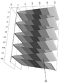
도 4는 이미지 생성 장치로서 기능하는 모니터의 휘도 분포를 도시하며;
도 5는 도 4에 따른 휘도 분포에 대한 보정 함수를 도시하고;
도 6은 이미지 생성 장치로서 기능하는 모니터의 표면에 걸쳐 연장되는 사인파 모양 이미지 패턴을 도시하며;
도 7은 도 5에 따른 보정 함수에 의해 변화된 도 6의 사인파 모양 이미지 패턴을 도시하고;
도 8은 본 발명에 따른 방법에 의해 최적화된 곡률도이며;
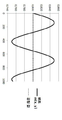
도 9는 이미지 생성 장치로서 기능하는 모니터의 폭에 걸친 사인파 모양 강도 분포를 도시하고;
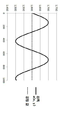
도 10은 이미지 생성 장치로서 기능하는 모니터의 폭에 걸친 비조정 강도 분포(non-adapted intensity distribution)를 도시하며;
도 11은 측정 물체의 표면으로부터의 반사 후, 이미지 생성 장치로서 기능하는, 모니터의 폭에 조정되지 않은 4개의 사인파 모양 강도 분포들을 도시하고;
도 12는, 일 예로서, 변조 다이어그램에서 도 11로부터 발생된 강도를 도시하며;
도 13은, 일 예로서, 진폭 다이어그램에서 도 12로부터 발생된 강도를 도시하고;
도 14는 선택된 적합한 보정 함수를 이용한 상업적으로 이용가능한 모니터의 감마이다. Now, there are other possibilities to practice and further develop the present disclosure in an advantageous manner. Reference numerals, on the one hand, are described for claims according to
1 is a schematic diagram of an exemplary embodiment of an apparatus according to the invention for implementing a method according to the invention;
2 shows the recording of the image pattern projected on the measurement object;
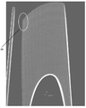
3 is a curvature diagram calculated from the record of FIG. 2;
4 shows the luminance distribution of a monitor functioning as an image generating device;
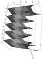
Fig. 5 shows a correction function for the luminance distribution according to Fig. 4;
Fig. 6 shows a sine wave shaped image pattern extending over the surface of the monitor functioning as the image generating device;
Fig. 7 shows the sine wave image pattern of Fig. 6 changed by the correction function according to Fig. 5;
8 is a curvature diagram optimized by the method according to the invention;
9 shows a sine wave shape intensity distribution across the width of a monitor functioning as an image generating device;
10 shows a non-adapted intensity distribution across the width of a monitor functioning as an image generating device;
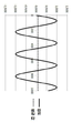
Fig. 11 shows four sine wave shape intensity distributions unadjusted to the width of the monitor, which function as an image generating device, after reflection from the surface of the measurement object;
12, as an example, shows the intensity generated from FIG. 11 in a modulation diagram;
13, as an example, shows the intensity generated from FIG. 12 in an amplitude diagram;
14 is a gamma of a commercially available monitor using a suitable calibration function selected.
도 1은 본 발명에 따른 방법을 실시하는 본 발명에 따른 장치의 예시적 디자인의 개략도이다. 본 장치는 예를 들어 모니터와 같은 이미지 생성 장치(1)를 포함한다. 이미지 생성 장치(1)는 측정 물체(2)에 투사되는 이미지 패턴을 묘사한다. 측정 물체(2)는, 예를 들어, 광학적으로 측정되는 표면을 가진 페인팅(painting)된 자동차일 수 있다. 본 장치는 캡쳐 장치(3), 구체적으로 카메라를 더 포함하고, 캡쳐 장치(3)의 시선(7)이 도 1에 도시되어 있다. 캡쳐 장치(3)는 반사, 산란, 회절 및/또는 전송을 통하여 측정 물체(2)에 의해 영향을 받은 이미지 패턴을 기록한다. 측정 물체에 투사되는 이미지 패턴을 최적화하기 위해, 이미지 생성 장치(1)는 보정 유닛(4)을 포함한다. 1 is a schematic diagram of an exemplary design of an apparatus according to the invention for implementing a method according to the invention. The device comprises an
예를 들어, 위상-이동 디플렉토메트리와 같은 광학 표면 측정은, 예를 들어, 조사되는 측정 물체(2)의 표면에 반사되는 사인파 모양 스트립들(sinusoidal strips)을 이용하여, 예를 들어, 모니터와 같은 이미지 생성 장치(1)에 표시된 이미지 패턴들의 기록을 필요로 한다. 캡쳐 장치(3)로서 기능하는 카메라의 각각의 픽셀에 대하여, 묘사되는 사인 패턴의 진폭 및 위상 위치는 기록된 영향을 받은 이미지 패턴들로부터 계산된다. 기록된 이미지 패턴들 내의 사인파의 진폭이 더욱 두드러질 수록, 계산 결과들이 더욱 안정된다; 약하게 나타나는 신호는 증가된 측정 노이즈로 이어진다. For example, optical surface measurements, such as phase-shifting deflectometry, can be performed using, for example, sinusoidal strips that are reflected on the surface of the
본질적으로, 기록 파라미터들(예를 들어, 노출 시간)을 변화시킴으로써 약하게 나타나는 신호를 최적화하는 것이 가능하다. 그러나, 기록 파라미터들은 카메라(3)의 동작 범위가 초과되지 않도록 선택되어야 한다. 카메라(3)는 0 내지 255의 범위에서 회색 색조들을 통상적으로 제공한다. 255의 값은 측정되는 표면 내에서 초과되지 않아야 한다. 이러한 과포화는 사인파의 캡핑(capping)으로 이어질 것이고, 이에 따라 사인파의 위상 위치는 더 이상 분명하게 결정되지 않을 것이다. Essentially, it is possible to optimize the weakly appearing signal by changing the recording parameters (eg, exposure time). However, the recording parameters must be selected so that the operating range of the
이상적으로, 기록된 사인 패턴은 0 내지 255의 전 범위를 포함한다. 실제로, 이는 다음과 같은 이유들로 인하여 가능하지 않다:Ideally, the recorded sine pattern covers the entire range from 0 to 255. In practice, this is not possible for the following reasons:
- 측정 물체(2)의 조사되는 표면에 의존하는 약간의 확산되는 반사 때문에, 묘사되는 사인 패턴이 오로지 직접적으로 반사되지는 않는다. 오히려, 결과는 모니터(1)의 휘도의 방사량의 2차원 평균화로 이루어지는 더 낮은 회색 값이다. -Due to the slight diffuse reflection depending on the irradiated surface of the
- 가동 중에, 기록된 영향을 받은 이미지 패턴들에서의 산란이 고려되어야 한다. 따라서, 장치를 설치할 때, 위 방향으로 대응하는 비어 있는 갭(free gap)을 항상 남겨두는 보호가 취해져야 한다. During operation, scattering in the recorded affected image patterns should be considered. Therefore, when installing the device, protection should always be taken to always leave a corresponding free gap in the upward direction.
- 설치 노력을 최소화하기 위해, 동일한 파라미터들을 이용하여 측정 물체(2)로서의 자동차의 전체 범위에 대하여 필요한 측정 위치들을 기록하는 것이 필요하다. 개별 위치들에서의 변화하는 자동차 기하학적 구조는 기록되는 이미지 패턴들의 강도에 또한 영향을 주고, 이에 따라 고려되어야 한다. -To minimize installation effort, it is necessary to record the required measurement positions for the entire range of the vehicle as the
도 2는 그립 오목부(grip recess)의 영역에서 자동차의 페인팅된 도어(door)의 부분의 예를 이용하여 영향을 받은 이미지 패턴으로서 스트립 패턴(strip pattern)의 반사의 기록을 도시한다. 기록 파라미터들은 이러한 예에서 올바르게 설정된다. 그럼에도 불구하고, 기록된 이미지 패턴의 개별 영역들에서의 사인 패턴 내의 명암비(contrast)의 차이들이 명확하게 보여진다. 제1 영역(5)은 다음과 같은 특성들을 가진 기록된 이미지 패턴의 가장 밝은 영역을 보여준다:FIG. 2 shows a record of reflection of a strip pattern as an image pattern affected using an example of a portion of a car's painted door in the area of a grip recess. Recording parameters are set correctly in this example. Nevertheless, differences in contrast in the sine pattern in individual areas of the recorded image pattern are clearly seen. The
- 기록된 이미지 패턴의 포화가 없다, 즉, 모든 회색 색조들 < 200, 즉, 255의 상한을 향하여 충분한 갭(gap)이 있다. There is no saturation of the recorded image pattern, i.e. there is sufficient gap towards the upper limit of all gray shades <200, i.e. 255.
- 가장 어두운 픽셀들은 근사적으로 130의 회색 색조를 가진다, 즉, 사인은 70의 회색 색조 진폭으로 묘사된다. 이는 충분하다. -The darkest pixels have an approximate gray tint of 130, ie the sine is depicted with a gray tint amplitude of 70. This is enough.
반면에, 제2 영역(6)에서, 사인 스트립들은 더 이상 충분한 명암비를 나타내지 않는다. 이는 계산된 곡률도에서 노이즈로 이어진다. 도 3은 도 2의 마킹된 제2 영역(6)을 가진 도 2의 도어 부분에 대한 곡률도를 도시한다. 여기서, 휘도는 나머지 영역과 비교하여 상당히 저하된다. On the other hand, in the
이러한 휘도 저하의 이유가 되는 측정 물체(2)의 표면은 그 자체가 배제될 수 있다. 이는 균일하게 페인팅되고 모든 곳에서 동일하게 반사한다. 더 정확히 말하면, 다음의 요인들이 주로 고려된다:The surface of the
·이미지 생성 장치(1)로서 사용되는 모니터의 불균일한 휘도 분포: 통상적으로 사용되는 모니터들(1)은 가장자리에서 중앙과 비교하여 20 내지 50 %의 휘도 저하를 가진다. -Non-uniform luminance distribution of the monitor used as the image generating device 1: The commonly used
·모니터(1)의 휘도 방사의 각도-의존성: 캡쳐 장치(3)로서 작용하는 카메라(3)의 시선(7)이 모니터(1)에 부딪치는 각도가 더 작을 수록, 카메라(3)에 의해 기록되는 강도가 작아질 수 있다. The angle-dependence of the luminance emission of the monitor 1: the smaller the angle at which the gaze 7 of the
도 2 및 3에 도시된 마킹(marking)된 영역들(5, 6)을 서로 비교하면, 2개의 현상의 조합은 관찰되는 휘도의 저하로 이어진다:Comparing the
영역 1:Zone 1:
·카메라(3)는 가장 높은 강도의 반사 광에 대하여 모니터(1)의 중앙 영역의 반사를 바라본다.-The
·카메라(3)의 시선(7)은 모니터(1)에 상대적으로 수직으로 부딪친다. · The eye 7 of the
영역 2:Zone 2:
·카메라(3)는, 대응하여 강도가 감소된, 모니터(1)의 코너들 중 하나의 반사를 바라본다. -The
·카메라(3)의 시선(7)은 상대적으로 작은 각도로 모니터에 부딪친다. · The eye 7 of the
본 발명에 따른 방법 및 본 발명에 따른 장치를 통하여, 기록 상황은, 기록된 영향을 받은 이미지 패턴이 균일한 휘도 분포를 나타내도록, 최적화된다. Through the method according to the invention and the apparatus according to the invention, the recording situation is optimized such that the recorded affected image pattern exhibits a uniform luminance distribution.
해결 수단의 기본적인 아이디어는 상술한 효과가 최소화될 정도로 모니터(1)에 표시되는 사인 패턴을 변조하는 것이다. 도 2의 이미지를 기록하기 위해, 모니터(1)의 모든 픽셀들에 대한 사인 패턴들은 0부터 255까지의 최대 이용가능 진폭의 회색 색조들을 이용하여 보여진다. 그러나, 이미 언급한 바와 같이, 기록은 130 내지 200의 회색 색조들만을 포함한다. 이는 서로 다른 요인들 중 표면의 확산된 반사에 의해 또한 야기되고, 이는 0에 가깝거나 0과 동일한 회색 색조를 가진 완벽한 흑색이 없는 이유이다. 따라서, 본 발명에 따르면, 기록을 향상시키기 위해, 사인 값들은 모니터(1)의 변화하는 국부 휘도 스팟(local brightness spots)을 균일화하도록 보정 값이 곱해진다:The basic idea of the solution is to modulate the sine pattern displayed on the
- 모니터(1)의 코너들은:-The corners of the
- 가장 어둡고, -The darkest,
- 0 내지 255의 전 범위, 즉, 인자 1이 사용되어야 한다.
-The entire range of 0 to 255, that is, the
- 모니터(1)의 중앙은:-The center of the monitor (1) is:
- 가장 밝고(예를 들어, 코너들보다 100% 더 밝고), -The brightest (for example, 100% brighter than the corners),
- 인자 0.5가 사인 값들에 곱해지며, -The factor 0.5 is multiplied by the sine values,
- 0 내지 127의 범위가 사용된다. -The range of 0 to 127 is used.
모니터의 중앙의 휘도를 낮춤으로써, 노출 시간은 과포화의 위험 없이 증가될 수 있고, 이는 모니터의 코너들에서의 기록되는 명암비를 증가시킨다. By lowering the brightness in the center of the monitor, the exposure time can be increased without the risk of oversaturation, which increases the contrast ratio recorded at the corners of the monitor.
모니터(1)에 표시된 백색 이미지들의 기록으로 시작하도록, 휘도 분포의 모양이 결정된다. 도 4는 모니터(1)에서의 위치에 대한 모니터(1)의 회색 색조들을 도시한다. 폭 8에 1900 픽셀들 및 높이 9에 1080 픽셀들을 가진 모니터(1)가 도시된다. 도 4의 z 축(10)은 110 내지 230의 범위로 미리 설정된 회색 색조들(11)을 나타낸다. 모니터(1)는 중앙에서 가장 밝은 반면에, 휘도가 코너들을 향하여 급격히 저하된다. To start with the recording of the white images displayed on the
이로부터, 2차원 보정 다항식은 필요한 인자가 각각의 픽셀에 대하여 계산될 수 있는 보정 함수로서 얻어질 수 있다. 보정 영역의 수학식은 사용되는 각각의 모니터 유형에 의존한다. 2개의 방향들에서 두드러지는 대칭성을 가진 4차까지의 다항식들은 실제 응용에서 유리한 것으로 증명되었다. From this, a two-dimensional correction polynomial can be obtained as a correction function in which necessary factors can be calculated for each pixel. The equation of the correction area depends on each monitor type used. Polynomials up to the fourth order with noticeable symmetry in two directions proved advantageous in practical applications.
도 5는 보정 함수, 즉, 모니터의 휘도 표현이 보정되는 x 및 y 방향에서의 보정 값들을 도시한다. 이 때문에, 모니터(1)에 보여지는 이미지 패턴의 회색 색조들은 곱셈이 행해진다. 이상적인 사인파는 통상적으로 묘사된다. 5 shows correction functions, that is, correction values in the x and y directions in which the luminance representation of the monitor is corrected. For this reason, the gray shades of the image pattern shown on the
도 6은 모니터(1)의 높이에 걸쳐 연장되는 사인파 모양 스트립들(12; x 방향에서 사인 패턴, y 방향에서 일정한 휘도)을 도시한다. 보정 후 결과는, 도 7에 도시된 바와 같이, 변조된 회색 색조들을 가진 모니터(1)의 표면에 걸쳐 조정된 사인파(13)이다. 중앙에서의 최대 휘도는 코너들과 비교하여 감소된다. 결과는 모니터(1)의 표면에 걸친 이미지 패턴의 균일한 휘도 분포이다. 6 shows sinusoidal strips 12 (sine pattern in the x direction, constant luminance in the y direction) extending over the height of the
보정 다항식을 결정하는 상술한 방법을 통하여, 모니터(1)의 불균일한 휘도 분포만이 우선 균일해진다. 모니터(1)의 각도-의존 휘도 방사에 의해 야기되는 추가적인 효과는 휘도 분포의 과잉 보상을 통하여 감소될 수 있고, 즉, 인자들을 결정하는 대신에 코너들과 동일한 휘도를 가지는 중앙이 묘사되도록, 코너들이 중앙보다 의도적으로 더 밝게 나타날 수 있다. 이는, 코너들에서의 휘도 감소가 약 25%뿐인, 더욱 최근의 디자인의 모니터들(1)에서 특히 실현가능하다. Through the above-described method of determining the correction polynomial, only the non-uniform luminance distribution of the
모니터(1)의 휘도 분포를 과잉 보정함으로써, 모니터의 코너들에서의 신호는 모니터의 중앙에서의 과포화의 위험 없이 향상될 수 있다. 분석된 예에서, 노출 시간을 더 증가시키는 것도 가능할 것이다. By overcorrecting the luminance distribution of the
향상은, 도 8에 도시된 바와 같이, 중요 영역들에서 상당히 감소된 노이즈 수준으로 분명해진다. 이는 제2 영역(6)에서 측정 값들의 균일한, 노이즈가 없거나 완전한 분포를 야기한다. The improvement is evident with significantly reduced noise levels in critical areas, as shown in FIG. 8. This results in a uniform, noise-free or complete distribution of the measured values in the
전체적으로 유사한 방식으로, 시야각-의존 휘도 분포를 보상하는 것이 가능할 것이다. 이를 위하여, 카메라(3)가 측정 물체(2)의 반사면을 관측하는 방위각(azimuth angle) 및 복각(polar angle)을 보정 함수로서 이용할 것이다. 이에 필요한 사인, 코사인( 또는 탄젠트)의 삼각 함수들 대신에, 모니터(1)의 폭 또는 높이 각각에만 의존하는 선형 함수가 1차 근사치에 관한 보정 함수로서 이용될 수 있다. 예를 들어 룩업 테이블을 이용하는 것과 같은 추가적인 보정 함수들이 동일한 방식으로 가능하다. In a similar way overall, it would be possible to compensate for the viewing angle-dependent luminance distribution. To this end, the azimuth angle and polar angle at which the
본 발명에 따른 방법의 예시적 실시형태를 구성하는 위상 측정 디플렉토메트리의 수학 기본 원칙이 이하에서 기술된다. The basic mathematical principles of the phase measurement deflectometry constituting an exemplary embodiment of the method according to the invention are described below.
위상-이동 디플렉토메트리의 확장 평가Extended evaluation of phase-shifting deflectometry
사인 스트립들이 샘플링되는 등거리 노드들의 수 k (k>2)에 독립적으로, 각각의 픽셀 (x, y)에 대하여, 3개의 독립된 정보가 평가된다(수학식들을 보라). 이를 위하여, 예를 들어, 스트립들의 각각이 등거리 위상 길이 ψk(위상 이동 90°)를 가지는 4개의 이미지들(Ik, 여기서 k = 1..4)이 기록된다. 다음의 이미지들은 이러한 이미지들 (Ik(x, y))로부터 계산될 수 있다: Independent of the number k (k> 2) of equidistant nodes from which the sine strips are sampled, three independent pieces of information are evaluated for each pixel (x, y) (see equations). To this end, for example, four images (I k , where k = 1..4) are recorded, each of which has an equidistant phase length ψ k (phase shift 90 °). The following images can be calculated from these images (I k (x, y)):
위상 이미지:Phase image:
![]()
![]()
점마다 얻어진 위상 이미지는 결과적으로 물체의 경사에 관한 정보가 된다. 소위 '경사 이미지'는, 예를 들어, 오목부들, 볼록부들 및 페인트 흐름들과 같은 복수의 표면 결함들을 평가하는 데에 적합하다. 미분을 통하여, '경사 이미지'는, 분명한 가장자리들을 가진 특히 작은 크기의 기하학적 결함들이 명확하게 보여질 수 있는 '곡률도'로 변화된다. 이에 대한 예들은 공동들, 스팟(spot)들, 새긴 자국들, 스크래치들(scratches)이다. The phase image obtained for each point becomes information about the inclination of the object as a result. The so-called 'inclined image' is suitable for evaluating a plurality of surface defects such as, for example, concave parts, convex parts and paint flows. Through differentiation, the 'tilted image' is transformed into a 'curvature diagram' in which geometrical defects of particularly small size with clear edges can be clearly seen. Examples of this are cavities, spots, indentations, and scratches.
회색 색조 이미지들:Grayscale images:
![]()
![]()
제2 정보 채널, 회색 색조 이미지는 위상-이동 베이스 이미지들(phase-shifted base images)로부터 합성을 통하여 노이즈가 특히 낮다. The second information channel, the grayscale image, has a particularly low noise through synthesis from phase-shifted base images.
변조 이미지 또는 명암비 이미지 (m, 회색 색조 이미지에 대한 정규화된 진폭): Modulated image or contrast image (m, normalized amplitude for grayscale images):
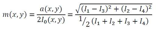
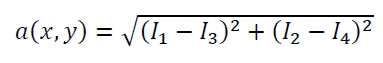
수학식 3에서, 다음의 수학식 4는 진폭이다. In
제3 정보 채널, 변조 이미지는 사인파가 특정 점에서 얼마나 강하게 존재하는지를 묘사하고, 표면의 국부적인 광택 수준을 표현한다. 이러한 표현은, 예를 들어, 먼지, 스크래치들 및 코팅 결함들과 같은 무광 영역들이 생길 때, 무광 영역들에 관한 중요 정보를 제공한다. The third information channel, the modulated image, describes how strongly a sine wave is present at a particular point and expresses the local gloss level of the surface. This expression provides important information about the matte areas when, for example, matte areas such as dust, scratches and coating defects occur.
도 9는 1000 픽셀들을 가진 모니터(1)의 폭에 걸친 사인파 모양 강도 분포를 도시한다. 이러한 경우, 모니터 폭은 사인 진행의 정수 배이고, 이는 모니터(1)의 전체 폭에 걸친 휘도(도 9에서 +/- 1로 정규화됨)의 평균 값이 정확히 0이 되게 한다. 9 shows a sine wave shape intensity distribution across the width of the
도 10은 모니터(1)의 폭에 걸친 비조정 사인파 모양 강도 분포를 도시한다. 이러한 경우, 모니터 폭은 사인 진행의 정수 배가 아니고, 이는 모니터(1)의 전체 폭에 걸친 휘도의 평균 값이 0과 달라지도록 한다. 10 shows the unadjusted sine wave shape intensity distribution over the width of the
휘도의 평균 값은, 특히, 부분적으로 반사되고 확산 산란되는 물체 표면에 대한 각각의 이미지 기록들에서 변화하는 베이스 휘도의 발생에 기여한다. 광의 반사 부분(본질적으로 본래의 사인 패턴)은 확산 산란 부분(본질적으로 표시된 패턴의 평균 휘도)을 통하여 부가적으로 중첩된다. The average value of luminance contributes, in particular, to the occurrence of varying base luminance in respective image records for the partially reflected and diffusely scattered object surface. The reflective portion of the light (essentially the original sine pattern) is additionally superimposed through the diffuse scattering portion (essentially the average luminance of the displayed pattern).
도 11은 측정 물체(2)의 표면으로부터의 반사 후, 모니터의 폭에 조정되지 않은 4개의 사인파 모양 강도 분포들(즉, 본질적으로 카메라(3)에 의해 기록된 이미지)을 도시한다. 사인파 모양 강도 분포 위상들의 각각은, 위상 측정 디플렉토메트리를 이용할 때의 경우, 90°씩 오프셋(offset)되어 있다. 위상 이동 원리로 인하여, 개별 기록들은 사인 진행의 서로 다른 부분들을 이제 묘사한다. 도 10에 도시된 효과는, 처음에, 모니터의 폭에 걸친 개별 사인 패턴들의 변화하는 평균 휘도 표시들로 이어진다. 따라서, 반사의 확산 부분과의 중첩은 각각의 이미지 패턴에 대한 평균 휘도 오프셋으로 이어진다. 이는, 각각, 결과 변조 이미지(수학식 3) 또는 진폭 이미지(수학식 4)에서의 휘도 변조를 야기한다. 조정된 사인 표현을 이용하면, 변조 이미지 또는 진폭 이미지는, 각각, 일정한 휘도를 보여줄 것이다. 수학식 3 및 4는 각각 4개의 이미지들 I1 내지 I4의 강도들을 포함한다. 각각 90°씩 위상 이동하고 폭에 조정된 4개의 사인파들의 추가는 모니터(1)의 (폭에 걸친) 일정한 값을 일으킬 것이다. 이는 도 12 및 13에서 점선에 의해 묘사된다. 그러나, 조정 누락은 사인파 모양 베이스 변조(변조 이미지에 대하여 도 12, 진폭 이미지에 대하여 도 13)를 야기하고, 이는 측정되는 표면의 확산 산란 부분과 함께 사인 패턴들의 적합하지 않은 선택에 의해 야기되고, 얻어진 측정 데이터의 잘못된 해석으로 이어진다. FIG. 11 shows four sine wave intensity distributions (ie, essentially the image recorded by the camera 3) unadjusted to the width of the monitor after reflection from the surface of the
사인 표현이 모니터의 폭에 조정되는 보정 함수를 통하여, 이러한 의도치 않은 효과가 방지될 수 있다. 상술한 설명은 모니터(1)의 높이에 동일하게 적용된다. This unintended effect can be prevented through a correction function in which the sine representation is adjusted to the width of the monitor. The above description applies equally to the height of the
도 14는 상업적으로 이용가능한 감마를 도시한다(실선). 모니터(1)의 휘도 표시에 대하여 적합하게 선택된 보정 함수(긴 점선)를 이용하여, 결과 이미지에 대한 선형 휘도 인상(짧은 점선)을 조정하는 것이 가능하다. 14 shows a commercially available gamma (solid line). By using a correction function (long dotted line) appropriately selected for the luminance display of the
본 발명에 따른 방법 및 본 발명에 따른 장치의 추가적인 유리한 실시형태들의 설명의 반복을 피하기 위해, 청구범위뿐만 아니라 발명의 설명의 일반적인 부분을 참조한다. In order to avoid repetition of the description of the further advantageous embodiments of the method according to the invention and the device according to the invention, reference is made to the claims as well as the general part of the description of the invention.
마지막으로, 본 발명에 따른 방법 및 본 발명에 따른 장치의 상술한 예시적 실시형태들은 청구된 개시의 설명으로서만 기능하고, 상술한 개시는 예시적 실시형태들로 제한되지 않는다는 사실을 분명하게 언급한다. Finally, it is explicitly mentioned that the above-described exemplary embodiments of the method according to the present invention and the device according to the present invention serve only as a description of the claimed disclosure, and the above-described disclosure is not limited to the exemplary embodiments. do.
1: 이미지 생성 장치
2: 측정 물체
3: 캡쳐 장치
4: 보정 유닛
5: 제1 영역
6: 제2 영역
7: 시선
8: 폭
9: 높이
10: z 축
11: 회색 색조들
12: 스트립들
13: 조정된 사인파1: Image generation device
2: measurement object
3: Capture device
4: correction unit
5: first area
6: Second area
7: Gaze
8: width
9: height
10: z axis
11: gray shades
12: Strips
13: tuned sine wave
Claims (12)
이미지 패턴은 이미지 생성 장치(1)를 이용하여 표시되고, 생성된 상기 이미지 패턴은 상기 측정 물체에 투사되며, 반사, 산란, 회절 및/또는 전송을 통하여 상기 측정 물체에 의해 영향을 받은 상기 이미지 패턴은 캡쳐 장치(3)를 이용하여 기록되고,
보정 함수에 의해, 상기 이미지 생성 장치(1) 및 이에 의해 표시된 상기 이미지 패턴은, 상기 캡쳐 장치(3)에 의해 기록된 상기 영향을 받은 상기 이미지 패턴이 적어도 본질적으로 일정한 및/또는 균일한 및/또는 선형적인 휘도를 시간적으로 및/또는 위치적으로 나타내도록, 조정되는
것을 특징으로 하는 측정 물체(2)의 표면을 광학적으로 측정하는 방법. In the method of optically measuring the surface of the measurement object (2),
The image pattern is displayed using the image generating device 1, and the generated image pattern is projected onto the measurement object, and the image pattern affected by the measurement object through reflection, scattering, diffraction and / or transmission Is recorded using the capture device 3,
By means of a correction function, the image generating device 1 and the image pattern displayed thereby are such that the affected image pattern recorded by the capture device 3 is at least essentially constant and / or uniform and / or Or adjusted to represent linear luminance temporally and / or positionally.
Method of optically measuring the surface of the measurement object (2), characterized in that.
이미지 패턴을 표시하는 이미지 생성 장치(1), 및 상기 측정 물체(2)로부터 반사, 산란, 회절 및/또는 전송에 의해 영향을 받은 상기 이미지 패턴을 기록하는 캡쳐 장치(3)를 포함하고,
상기 이미지 생성 장치(1)에는, 상기 캡쳐 장치(3)에 의해 기록된 영향을 받은 상기 이미지 패턴이 적어도 본질적으로 일정한 및/또는 균일한 및/또는 선형적인 휘도를 시간적으로 및/또는 위치적으로 나타내도록, 표시된 상기 이미지 패턴을 보정 함수를 통하여 조정하는 보정 유닛(4)이 제공되는
것을 특징으로 하는 측정 물체(2)의 표면을 광학적으로 측정하는 방법을 실시하는 장치.An apparatus for carrying out a method for optically measuring the surface of a measurement object (2) according to any one of claims 1 to 11,
An image generating device 1 displaying an image pattern, and a capturing device 3 recording the image pattern affected by reflection, scattering, diffraction and / or transmission from the measurement object 2,
In the image generating device 1, the affected image pattern recorded by the capture device 3 is at least essentially constant and / or uniform and / or linear in luminance and / or positionally in time. A correction unit 4 is provided to adjust the displayed image pattern through a correction function to indicate
Apparatus for performing a method of optically measuring the surface of a measurement object (2), characterized in that.
Applications Claiming Priority (3)
| Application Number | Priority Date | Filing Date | Title |
|---|---|---|---|
| DE102017211377.4 | 2017-07-04 | ||
| DE102017211377.4A DE102017211377B4 (en) | 2017-07-04 | 2017-07-04 | Method and device for optical surface measurement of a measurement object |
| PCT/DE2018/200050 WO2019007468A1 (en) | 2017-07-04 | 2018-05-18 | Method and device for optically measuring the surface of a measurement object |
Publications (2)
| Publication Number | Publication Date |
|---|---|
| KR20200028406A true KR20200028406A (en) | 2020-03-16 |
| KR102398723B1 KR102398723B1 (en) | 2022-05-17 |
Family
ID=63144783
Family Applications (1)
| Application Number | Title | Priority Date | Filing Date |
|---|---|---|---|
| KR1020207003010A KR102398723B1 (en) | 2017-07-04 | 2018-05-18 | Method and apparatus for optically measuring the surface of a measurement object |
Country Status (7)
| Country | Link |
|---|---|
| US (2) | US11125550B2 (en) |
| EP (1) | EP3479059A1 (en) |
| JP (1) | JP7016892B2 (en) |
| KR (1) | KR102398723B1 (en) |
| CN (1) | CN110832271B (en) |
| DE (1) | DE102017211377B4 (en) |
| WO (1) | WO2019007468A1 (en) |
Cited By (2)
| Publication number | Priority date | Publication date | Assignee | Title |
|---|---|---|---|---|
| KR20230055316A (en) * | 2021-10-18 | 2023-04-25 | 라이트비전 주식회사 | System and method of generating tem sadp image with high discernment |
| WO2023068631A1 (en) * | 2021-10-18 | 2023-04-27 | 라이트비전 주식회사 | System and method for generating tem sadp image with high distinguishability |
Families Citing this family (4)
| Publication number | Priority date | Publication date | Assignee | Title |
|---|---|---|---|---|
| KR101955847B1 (en) * | 2018-01-23 | 2019-03-11 | 한국표준과학연구원 | Method and system for compensating nonlinearity response characteristics in phase-shifting deflectometry |
| US11328380B2 (en) * | 2018-10-27 | 2022-05-10 | Gilbert Pinter | Machine vision systems, illumination sources for use in machine vision systems, and components for use in the illumination sources |
| JP7310218B2 (en) * | 2019-03-28 | 2023-07-19 | セイコーエプソン株式会社 | Three-dimensional measuring method, three-dimensional measuring device and robot system |
| CN115086627B (en) * | 2022-06-06 | 2023-05-30 | 岚图汽车科技有限公司 | Projector control method and device and vehicle |
Citations (2)
| Publication number | Priority date | Publication date | Assignee | Title |
|---|---|---|---|---|
| US6256010B1 (en) * | 1997-06-30 | 2001-07-03 | Industrial Technology Research Institute | Dynamic correction of LCD gamma curve |
| US20070206204A1 (en) * | 2005-12-01 | 2007-09-06 | Peirong Jia | Full-field three-dimensional measurement method |
Family Cites Families (3)
| Publication number | Priority date | Publication date | Assignee | Title |
|---|---|---|---|---|
| CN103292734B (en) * | 2013-05-27 | 2015-10-28 | 华中科技大学 | Gamma value scaling method in phase measuring system |
| CN103983208A (en) * | 2014-05-09 | 2014-08-13 | 南昌航空大学 | Out-of-focus projection three-dimensional measurement method of color binary fringes |
| CN105403172B (en) * | 2015-10-27 | 2018-07-20 | 华侨大学 | Subregion Gamma pre-calibration phase error compensating methods during a kind of big visual field structure light vision measures |
-
2017
- 2017-07-04 DE DE102017211377.4A patent/DE102017211377B4/en active Active
-
2018
- 2018-05-18 US US16/627,161 patent/US11125550B2/en active Active
- 2018-05-18 EP EP18752414.5A patent/EP3479059A1/en active Pending
- 2018-05-18 JP JP2019571620A patent/JP7016892B2/en active Active
- 2018-05-18 WO PCT/DE2018/200050 patent/WO2019007468A1/en unknown
- 2018-05-18 KR KR1020207003010A patent/KR102398723B1/en active IP Right Grant
- 2018-05-18 CN CN201880044995.8A patent/CN110832271B/en active Active
-
2021
- 2021-07-16 US US17/378,571 patent/US20210364277A1/en active Pending
Patent Citations (2)
| Publication number | Priority date | Publication date | Assignee | Title |
|---|---|---|---|---|
| US6256010B1 (en) * | 1997-06-30 | 2001-07-03 | Industrial Technology Research Institute | Dynamic correction of LCD gamma curve |
| US20070206204A1 (en) * | 2005-12-01 | 2007-09-06 | Peirong Jia | Full-field three-dimensional measurement method |
Non-Patent Citations (1)
| Title |
|---|
| An accurate projector gamma correction method for phase-measuring profilometry based on direct optical power detection(Miao LIU 등 4인, doi: 10.1117/12.2199669. 공지시점 2015년)* * |
Cited By (3)
| Publication number | Priority date | Publication date | Assignee | Title |
|---|---|---|---|---|
| KR20230055316A (en) * | 2021-10-18 | 2023-04-25 | 라이트비전 주식회사 | System and method of generating tem sadp image with high discernment |
| KR20230055317A (en) * | 2021-10-18 | 2023-04-25 | 라이트비전 주식회사 | System and method of converting imaginary tem sadp image to real tem sadp image or real tem sadp image to imaginary tem sadp image using deep learning |
| WO2023068631A1 (en) * | 2021-10-18 | 2023-04-27 | 라이트비전 주식회사 | System and method for generating tem sadp image with high distinguishability |
Also Published As
| Publication number | Publication date |
|---|---|
| JP2020527225A (en) | 2020-09-03 |
| CN110832271A (en) | 2020-02-21 |
| CN110832271B (en) | 2022-11-11 |
| US11125550B2 (en) | 2021-09-21 |
| US20200158498A1 (en) | 2020-05-21 |
| JP7016892B2 (en) | 2022-02-07 |
| EP3479059A1 (en) | 2019-05-08 |
| KR102398723B1 (en) | 2022-05-17 |
| DE102017211377B4 (en) | 2021-01-14 |
| DE102017211377A1 (en) | 2019-01-10 |
| WO2019007468A1 (en) | 2019-01-10 |
| US20210364277A1 (en) | 2021-11-25 |
Similar Documents
| Publication | Publication Date | Title |
|---|---|---|
| KR102398723B1 (en) | Method and apparatus for optically measuring the surface of a measurement object | |
| US11930304B2 (en) | System and method for providing improved display quality by display adjustment and image processing using optical feedback | |
| US8195006B2 (en) | Method and device for representing a digital image on a surface which is non-trivial in terms of its geometry and photometry | |
| US10798373B2 (en) | Display correction apparatus, program, and display correction system | |
| US6727864B1 (en) | Method and apparatus for an optical function generator for seamless tiled displays | |
| US7614753B2 (en) | Determining an adjustment | |
| US8111290B2 (en) | Radiometric calibration using temporal irradiance mixtures | |
| JP2005099150A (en) | Image correction data calculation method of image display apparatus | |
| KR100417629B1 (en) | Imaging System | |
| Fischer et al. | Evaluation of LCD monitors for deflectometric measurement systems | |
| JP6350356B2 (en) | Image processing apparatus, projector, image processing method, and program | |
| JP2004334056A (en) | Method and device for focus adjustment of projector | |
| Zietlow et al. | Advanced luminance control and black offset correction for multi-projector display systems | |
| JP2009186546A (en) | Projector and projection method |
Legal Events
| Date | Code | Title | Description |
|---|---|---|---|
| E902 | Notification of reason for refusal | ||
| E701 | Decision to grant or registration of patent right | ||
| GRNT | Written decision to grant |