KR20200028020A - Method and apparatus for performing congestion control in NR V2X - Google Patents
Method and apparatus for performing congestion control in NR V2X Download PDFInfo
- Publication number
- KR20200028020A KR20200028020A KR1020207005373A KR20207005373A KR20200028020A KR 20200028020 A KR20200028020 A KR 20200028020A KR 1020207005373 A KR1020207005373 A KR 1020207005373A KR 20207005373 A KR20207005373 A KR 20207005373A KR 20200028020 A KR20200028020 A KR 20200028020A
- Authority
- KR
- South Korea
- Prior art keywords
- sidelink
- slot
- measurement
- channel
- symbols
- Prior art date
Links
- 238000000034 method Methods 0.000 title claims abstract description 104
- 238000005259 measurement Methods 0.000 claims abstract description 145
- 238000004891 communication Methods 0.000 claims abstract description 139
- 230000005540 biological transmission Effects 0.000 claims description 103
- 230000015654 memory Effects 0.000 claims description 65
- 239000010410 layer Substances 0.000 description 50
- 230000006870 function Effects 0.000 description 29
- 238000013473 artificial intelligence Methods 0.000 description 23
- 238000005516 engineering process Methods 0.000 description 21
- 230000008569 process Effects 0.000 description 19
- 238000012545 processing Methods 0.000 description 17
- 230000000737 periodic effect Effects 0.000 description 8
- 230000011664 signaling Effects 0.000 description 8
- 238000013468 resource allocation Methods 0.000 description 7
- 238000007726 management method Methods 0.000 description 6
- 230000001133 acceleration Effects 0.000 description 4
- 238000012549 training Methods 0.000 description 4
- 230000007774 longterm Effects 0.000 description 3
- 238000013507 mapping Methods 0.000 description 3
- 230000003287 optical effect Effects 0.000 description 3
- 230000005856 abnormality Effects 0.000 description 2
- 239000000969 carrier Substances 0.000 description 2
- 230000008859 change Effects 0.000 description 2
- 125000004122 cyclic group Chemical group 0.000 description 2
- 230000000694 effects Effects 0.000 description 2
- 238000005562 fading Methods 0.000 description 2
- 239000011521 glass Substances 0.000 description 2
- 238000010295 mobile communication Methods 0.000 description 2
- 239000004984 smart glass Substances 0.000 description 2
- 238000012546 transfer Methods 0.000 description 2
- 238000005406 washing Methods 0.000 description 2
- 102100022734 Acyl carrier protein, mitochondrial Human genes 0.000 description 1
- 101000678845 Homo sapiens Acyl carrier protein, mitochondrial Proteins 0.000 description 1
- 230000027311 M phase Effects 0.000 description 1
- 230000009471 action Effects 0.000 description 1
- 230000006978 adaptation Effects 0.000 description 1
- 230000003044 adaptive effect Effects 0.000 description 1
- 230000002411 adverse Effects 0.000 description 1
- 238000004873 anchoring Methods 0.000 description 1
- 238000003491 array Methods 0.000 description 1
- 238000013528 artificial neural network Methods 0.000 description 1
- 230000003190 augmentative effect Effects 0.000 description 1
- 230000006835 compression Effects 0.000 description 1
- 238000007906 compression Methods 0.000 description 1
- 238000012937 correction Methods 0.000 description 1
- 238000007405 data analysis Methods 0.000 description 1
- 238000001514 detection method Methods 0.000 description 1
- 230000007613 environmental effect Effects 0.000 description 1
- 239000000446 fuel Substances 0.000 description 1
- 238000005286 illumination Methods 0.000 description 1
- 239000002346 layers by function Substances 0.000 description 1
- 238000010801 machine learning Methods 0.000 description 1
- 239000011159 matrix material Substances 0.000 description 1
- 230000008520 organization Effects 0.000 description 1
- 230000010363 phase shift Effects 0.000 description 1
- 230000002441 reversible effect Effects 0.000 description 1
- 230000011218 segmentation Effects 0.000 description 1
- 238000010187 selection method Methods 0.000 description 1
- 230000008054 signal transmission Effects 0.000 description 1
- 239000010454 slate Substances 0.000 description 1
- 238000001228 spectrum Methods 0.000 description 1
- 230000009466 transformation Effects 0.000 description 1
Images


Classifications
-
- H—ELECTRICITY
- H04—ELECTRIC COMMUNICATION TECHNIQUE
- H04W—WIRELESS COMMUNICATION NETWORKS
- H04W76/00—Connection management
- H04W76/10—Connection setup
- H04W76/14—Direct-mode setup
-
- H—ELECTRICITY
- H04—ELECTRIC COMMUNICATION TECHNIQUE
- H04W—WIRELESS COMMUNICATION NETWORKS
- H04W28/00—Network traffic management; Network resource management
- H04W28/02—Traffic management, e.g. flow control or congestion control
- H04W28/0284—Traffic management, e.g. flow control or congestion control detecting congestion or overload during communication
-
- H—ELECTRICITY
- H04—ELECTRIC COMMUNICATION TECHNIQUE
- H04W—WIRELESS COMMUNICATION NETWORKS
- H04W74/00—Wireless channel access, e.g. scheduled or random access
- H04W74/08—Non-scheduled or contention based access, e.g. random access, ALOHA, CSMA [Carrier Sense Multiple Access]
- H04W74/0808—Non-scheduled or contention based access, e.g. random access, ALOHA, CSMA [Carrier Sense Multiple Access] using carrier sensing, e.g. as in CSMA
-
- H—ELECTRICITY
- H04—ELECTRIC COMMUNICATION TECHNIQUE
- H04B—TRANSMISSION
- H04B17/00—Monitoring; Testing
- H04B17/30—Monitoring; Testing of propagation channels
- H04B17/309—Measuring or estimating channel quality parameters
- H04B17/318—Received signal strength
-
- H—ELECTRICITY
- H04—ELECTRIC COMMUNICATION TECHNIQUE
- H04B—TRANSMISSION
- H04B17/00—Monitoring; Testing
- H04B17/30—Monitoring; Testing of propagation channels
- H04B17/391—Modelling the propagation channel
- H04B17/3913—Predictive models, e.g. based on neural network models
-
- H—ELECTRICITY
- H04—ELECTRIC COMMUNICATION TECHNIQUE
- H04L—TRANSMISSION OF DIGITAL INFORMATION, e.g. TELEGRAPHIC COMMUNICATION
- H04L1/00—Arrangements for detecting or preventing errors in the information received
- H04L1/12—Arrangements for detecting or preventing errors in the information received by using return channel
- H04L1/16—Arrangements for detecting or preventing errors in the information received by using return channel in which the return channel carries supervisory signals, e.g. repetition request signals
- H04L1/18—Automatic repetition systems, e.g. Van Duuren systems
- H04L1/1812—Hybrid protocols; Hybrid automatic repeat request [HARQ]
- H04L1/1819—Hybrid protocols; Hybrid automatic repeat request [HARQ] with retransmission of additional or different redundancy
-
- H—ELECTRICITY
- H04—ELECTRIC COMMUNICATION TECHNIQUE
- H04W—WIRELESS COMMUNICATION NETWORKS
- H04W24/00—Supervisory, monitoring or testing arrangements
- H04W24/08—Testing, supervising or monitoring using real traffic
-
- H—ELECTRICITY
- H04—ELECTRIC COMMUNICATION TECHNIQUE
- H04W—WIRELESS COMMUNICATION NETWORKS
- H04W24/00—Supervisory, monitoring or testing arrangements
- H04W24/10—Scheduling measurement reports ; Arrangements for measurement reports
-
- H—ELECTRICITY
- H04—ELECTRIC COMMUNICATION TECHNIQUE
- H04W—WIRELESS COMMUNICATION NETWORKS
- H04W28/00—Network traffic management; Network resource management
- H04W28/02—Traffic management, e.g. flow control or congestion control
- H04W28/0289—Congestion control
-
- H—ELECTRICITY
- H04—ELECTRIC COMMUNICATION TECHNIQUE
- H04W—WIRELESS COMMUNICATION NETWORKS
- H04W4/00—Services specially adapted for wireless communication networks; Facilities therefor
- H04W4/30—Services specially adapted for particular environments, situations or purposes
- H04W4/40—Services specially adapted for particular environments, situations or purposes for vehicles, e.g. vehicle-to-pedestrians [V2P]
-
- H—ELECTRICITY
- H04—ELECTRIC COMMUNICATION TECHNIQUE
- H04W—WIRELESS COMMUNICATION NETWORKS
- H04W72/00—Local resource management
- H04W72/12—Wireless traffic scheduling
-
- H—ELECTRICITY
- H04—ELECTRIC COMMUNICATION TECHNIQUE
- H04W—WIRELESS COMMUNICATION NETWORKS
- H04W72/00—Local resource management
- H04W72/50—Allocation or scheduling criteria for wireless resources
- H04W72/54—Allocation or scheduling criteria for wireless resources based on quality criteria
- H04W72/542—Allocation or scheduling criteria for wireless resources based on quality criteria using measured or perceived quality
-
- H—ELECTRICITY
- H04—ELECTRIC COMMUNICATION TECHNIQUE
- H04W—WIRELESS COMMUNICATION NETWORKS
- H04W92/00—Interfaces specially adapted for wireless communication networks
- H04W92/16—Interfaces between hierarchically similar devices
- H04W92/18—Interfaces between hierarchically similar devices between terminal devices
-
- H—ELECTRICITY
- H04—ELECTRIC COMMUNICATION TECHNIQUE
- H04W—WIRELESS COMMUNICATION NETWORKS
- H04W28/00—Network traffic management; Network resource management
- H04W28/02—Traffic management, e.g. flow control or congestion control
- H04W28/0231—Traffic management, e.g. flow control or congestion control based on communication conditions
-
- H—ELECTRICITY
- H04—ELECTRIC COMMUNICATION TECHNIQUE
- H04W—WIRELESS COMMUNICATION NETWORKS
- H04W72/00—Local resource management
- H04W72/04—Wireless resource allocation
- H04W72/044—Wireless resource allocation based on the type of the allocated resource
- H04W72/0446—Resources in time domain, e.g. slots or frames
-
- H—ELECTRICITY
- H04—ELECTRIC COMMUNICATION TECHNIQUE
- H04W—WIRELESS COMMUNICATION NETWORKS
- H04W72/00—Local resource management
- H04W72/50—Allocation or scheduling criteria for wireless resources
- H04W72/56—Allocation or scheduling criteria for wireless resources based on priority criteria
Abstract
제 1 장치(100)가 사이드링크 통신을 수행하는 방법 및 이를 지원하는 장치가 제공된다. 상기 방법은, 제 1 자원 단위를 기반으로, CR(Channel occupancy Ratio) 측정 또는 CBR(Channel Busy Ratio) 측정 중 적어도 어느 하나를 수행하는 단계; 및 상기 측정을 기반으로 상기 사이드링크 통신을 수행하는 단계;를 포함하되, 상기 제 1 자원 단위의 심볼의 개수는 자원 풀 내의 복수의 슬롯 중에서 제 1 슬롯에 포함된 사이드링크와 관련된 심볼의 개수일 수 있다.A method for performing a sidelink communication by the first device 100 and an apparatus supporting the same are provided. The method includes: performing at least one of a channel occupancy ratio (CR) measurement or a channel busy ratio (CBR) measurement based on a first resource unit; And performing the sidelink communication based on the measurement, wherein the number of symbols in the first resource unit is the number of symbols related to the sidelink included in the first slot among the plurality of slots in the resource pool. You can.
Description
본 발명은 무선 통신 시스템에 관한 것이다.The present invention relates to a wireless communication system.
무선 통신 시스템은 가용한 시스템 자원(예를 들어, 대역폭, 전송 파워 등)을 공유하여 다중 사용자와의 통신을 지원하는 다중 접속(multiple access) 시스템이다. 다중 접속 시스템의 예로는 CDMA(code division multiple access) 시스템, FDMA(frequency division multiple access) 시스템, TDMA(time division multiple access) 시스템, OFDMA(orthogonal frequency division multiple access) 시스템, SC-FDMA(single carrier frequency division multiple access) 시스템, MC-FDMA(multi carrier frequency division multiple access) 시스템 등이 있다.A wireless communication system is a multiple access system that supports communication with multiple users by sharing available system resources (eg, bandwidth, transmission power, etc.). Examples of the multiple access system include a code division multiple access (CDMA) system, a frequency division multiple access (FDMA) system, a time division multiple access (TDMA) system, an orthogonal frequency division multiple access (OFDMA) system, and a single carrier frequency (SC-FDMA). division multiple access (MC), multi-carrier frequency division multiple access (MC-FDMA) systems.
한편, 무선 통신 시스템에서는 데이터의 송/수신, 시스템 동기 획득, 채널 정보 피드백 등을 위하여 상향링크 채널 또는 하향링크의 채널을 추정할 필요가 있다. 무선통신 시스템 환경에서는 다중 경로 시간 지연으로 인하여 페이딩이 발생하게 된다. 페이딩으로 인한 급격한 환경 변화에 의하여 생기는 신호의 왜곡을 보상하여 전송 신호를 복원하는 과정을 채널 추정이라고 한다. 또한 단말이 속한 셀 혹은 다른 셀에 대한 채널 상태(channel state)를 측정할 필요가 있다. 채널 추정 또는 채널 상태 측정을 위해서 일반적으로 송수신기가 상호 간에 알고 있는 참조 신호(RS; reference signal)를 이용하여 채널 추정을 수행하게 된다.Meanwhile, in a wireless communication system, it is necessary to estimate an uplink channel or a downlink channel for data transmission / reception, system synchronization acquisition, and channel information feedback. In a wireless communication system environment, fading occurs due to multipath time delay. The process of restoring a transmission signal by compensating for distortion of a signal caused by a rapid environmental change due to fading is called channel estimation. In addition, it is necessary to measure the channel state (channel state) for the cell or other cell to which the terminal belongs. For channel estimation or channel state measurement, channel estimation is generally performed using a reference signal (RS) that transceivers know each other.
단말은 다음 3가지 방법으로 측정을 수행할 수 있다.The UE can perform measurement in the following three ways.
1) RSRP(reference signal received power): 전 대역에 걸쳐 전송되는 CRS를 운반하는 모든 RE의 평균 수신 전력을 나타낸다. 이때 CRS 대신 CSI RS를 운반하는 모든 RE의 평균 수신 전력을 측정할 수도 있다.1) RSRP (reference signal received power): represents the average received power of all REs carrying CRS transmitted over the entire band. In this case, the average received power of all REs carrying the CSI RS instead of the CRS may be measured.
2) RSSI(received signal strength indicator): 전체 대역에서 측정된 수신 전력을 나타낸다. RSSI는 신호, 간섭(interference), 열 잡음(thermal noise)을 모두 포함한다. 2) RSSI (received signal strength indicator): indicates the received power measured in the entire band. RSSI includes signal, interference, and thermal noise.
3) RSRQ(reference symbol received quality): CQI를 나타내며, 측정 대역폭(bandwidth) 또는 서브밴드에 따른 RSRP/RSSI로 결정될 수 있다. 즉, RSRQ는 신호 대 잡음 간섭 비(SINR; signal-to-noise interference ratio)를 의미한다. RSRP는 충분한 이동성(mobility) 정보를 제공하지 못하므로, 핸드오버 또는 셀 재선택(cell reselection) 과정에서는 RSRP 대신 RSRQ가 대신 사용될 수 있다. 3) RSRQ (reference symbol received quality): indicates CQI, and may be determined by RSRP / RSSI according to measurement bandwidth or subband. That is, RSRQ refers to a signal-to-noise interference ratio (SINR). Since RSRP does not provide sufficient mobility information, RSRQ may be used instead of RSRP in handover or cell reselection.
RSRQ = RSSI/RSSP로 산출될 수 있다. 또는 RSRQ = N*RSSI/RSSP로 산출될 수도 있다. 여기서 N은 RSSI를 측정하는 대역폭에 관련된 변수(예컨대 PRB 개수) 또는 함수일 수 있다.RSRQ = RSSI / RSSP. Alternatively, RSRQ = N * RSSI / RSSP may be calculated. Here, N may be a variable (eg, the number of PRBs) or a function related to a bandwidth for measuring RSSI.
한편, 사이드링크(sidelink)란 단말(User Equipment, UE)들 간에 직접적인 링크를 설정하여, 기지국(Base Station, BS)을 거치지 않고, 단말 간에 음성 또는 데이터 등을 직접 주고 받는 통신 방식을 말한다. 사이드링크는 급속도로 증가하는 데이터 트래픽에 따른 기지국의 부담을 해결할 수 있는 하나의 방안으로서 고려되고 있다.On the other hand, a sidelink (sidelink) refers to a communication method that establishes a direct link between UEs (User Equipment, UEs) and directly exchanges voice or data between terminals without going through a base station (BS). The side link is considered as one method to solve the burden of the base station due to the rapidly increasing data traffic.
V2X(vehicle-to-everything)는 유/무선 통신을 통해 다른 차량, 보행자, 인프라가 구축된 사물 등과 정보를 교환하는 통신 기술을 의미한다. V2X는 V2V(vehicle-to-vehicle), V2I(vehicle-to-infrastructure), V2N(vehicle-to- network) 및 V2P(vehicle-to-pedestrian)와 같은 4 가지 유형으로 구분될 수 있다. V2X 통신은 PC5 인터페이스 및/또는 Uu 인터페이스를 통해 제공될 수 있다.V2X (vehicle-to-everything) means a communication technology that exchanges information with other vehicles, pedestrians, and infrastructure-built objects through wired / wireless communication. V2X can be divided into four types: vehicle-to-vehicle (V2V), vehicle-to-infrastructure (V2I), vehicle-to-network (V2N), and vehicle-to-pedestrian (V2P). V2X communication may be provided through a PC5 interface and / or a Uu interface.
한편, 더욱 많은 통신 기기들이 더욱 큰 통신 용량을 요구하게 됨에 따라, 기존의 무선 액세스 기술(Radio Access Technology, RAT)에 비해 향상된 모바일 광대역 (mobile broadband) 통신에 대한 필요성이 대두되고 있다. 이에 따라, 신뢰도(reliability) 및 지연(latency)에 민감한 서비스 또는 단말을 고려한 통신 시스템이 논의되고 있는데, 개선된 이동 광대역 통신, 매시브 MTC, URLLC(Ultra-Reliable and Low Latency Communication) 등을 고려한 차세대 무선 접속 기술을 새로운 RAT(new radio access technology) 또는 NR(new radio)이라 칭할 수 있다. NR에서도 V2X(vehicle-to-everything) 통신이 지원될 수 있다.Meanwhile, as more communication devices require a larger communication capacity, a need for an improved mobile broadband communication has emerged compared to a conventional radio access technology (RAT). Accordingly, a communication system considering a service or terminal sensitive to reliability and latency is being discussed. Next-generation wireless considering improved mobile broadband communication, Massive MTC, and Ultra-Reliable and Low Latency Communication (URLLC). The access technology may be referred to as a new radio access technology (RAT) or a new radio (NR). Vehicle-to-everything (V2X) communication may also be supported in NR.
한편, NR 사이드링크 또는 NR V2X의 경우에, 유연한(flexible) 슬롯 포맷이 지원된다. 따라서, 유연한 슬롯 포맷을 고려한 사이드링크 통신 방법 및 이를 지원하는 장치가 제안될 필요가 있다.Meanwhile, in the case of NR sidelink or NR V2X, a flexible slot format is supported. Accordingly, there is a need to propose a sidelink communication method considering a flexible slot format and an apparatus supporting the same.
일 실시 예에 있어서, 제 1 장치(100)가 사이드링크 통신을 수행하는 방법이 제공된다. 상기 방법은, 제 1 자원 단위를 기반으로, CR(Channel occupancy Ratio) 측정 또는 CBR(Channel Busy Ratio) 측정 중 적어도 어느 하나를 수행하는 단계; 및 상기 측정을 기반으로 상기 사이드링크 통신을 수행하는 단계;를 포함하되, 상기 제 1 자원 단위의 심볼의 개수는 자원 풀 내의 복수의 슬롯 중에서 제 1 슬롯에 포함된 사이드링크와 관련된 심볼의 개수일 수 있다. In one embodiment, a method is provided in which the
다른 실시 예에 있어서, 사이드링크 통신을 수행하는 제 1 장치(100)가 제공된다. 상기 제 1 장치(100)는 하나 이상이 메모리; 하나 이상의 송수신기; 및 상기 하나 이상의 메모리와 상기 하나 이상의 송수신기를 연결하는 하나 이상의 프로세서를 포함하되, 상기 프로세서는 제 1 자원 단위를 기반으로, CR(Channel occupancy Ratio) 측정 또는 CBR(Channel Busy Ratio) 측정 중 적어도 어느 하나를 수행하고, 및 상기 측정을 기반으로 상기 사이드링크 통신을 수행하도록 송수신기를 제어하되, 상기 제 1 자원 단위의 심볼의 개수는 자원 풀 내의 복수의 슬롯 중에서 제 1 슬롯에 포함된 사이드링크와 관련된 심볼의 개수일 수 있다.In another embodiment, a
단말이 효율적으로 사이드링크 통신을 수행할 수 있다.The terminal can efficiently perform sidelink communication.
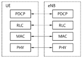
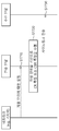
도 1은 본 발명의 실시 예가 적용될 수 있는 LTE 시스템의 구조를 나타낸다.
도 2는 본 발명의 실시 예가 적용될 수 있는 사용자 평면(user plane)에 대한 무선 프로토콜 구조(radio protocol architecture)를 나타낸다.
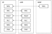
도 3은 본 발명의 실시 예가 적용될 수 있는 제어 평면(control plane)에 대한 무선 프로토콜 구조를 나타낸다.
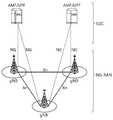
도 4는 본 발명의 실시 예가 적용될 수 있는 NR 시스템의 구조를 나타낸다.
도 5는 본 발명의 실시 예가 적용될 수 있는 NG-RAN과 5GC 간의 기능적 분할을 나타낸다.
도 6은 본 발명의 실시 예가 적용될 수 있는 NR의 무선 프레임의 구조를 나타낸다.
도 7은 본 발명의 실시 예가 적용될 수 있는 NR 프레임의 슬롯 구조를 나타낸다.
도 8은 본 발명의 실시 예가 적용될 수 있는 BWP의 일 예를 나타낸다.
도 9는 본 발명의 실시 예가 적용될 수 있는 사이드링크 통신을 위한 프로토콜 스택(protocol stack)을 나타낸다.
도 10은 본 발명의 실시 예가 적용될 수 있는 사이드링크 통신을 위한 프로토콜 스택(protocol stack)을 나타낸다.
도 11은 본 발명의 실시 예가 적용될 수 있는 V2X 또는 사이드링크 통신을 수행하는 단말을 나타낸다.
도 12는 본 발명의 실시 예가 적용될 수 있는 자원 단위의 구성의 일 예를 나타낸다.
도 13은 본 발명의 실시 예가 적용될 수 있는 사이드링크/V2X 통신과 관련된 전송 모드(transmission mode, TM)에 따른 단말 동작을 나타낸다.
도 14는 본 발명의 실시 예가 적용될 수 있는 전송 자원이 선택되는 예를 나타낸다.
도 15는 본 발명의 실시 예가 적용될 수 있는 CBR의 일 예를 나타낸다.
도 16은 본 발명의 실시 예가 적용될 수 있는 슬롯 포맷의 일 예를 나타낸다.
도 17은 본 발명의 일 실시 예에 따라, 단말이 기본 자원 단위(basic resource unit)를 기반으로 CR 측정 또는 CBR 측정을 수행하는 방법을 나타낸다.
도 18은 본 발명의 일 실시 예에 따른 기본 자원 단위의 일 예를 나타낸다.
도 19는 본 발명의 일 실시 예에 따라, 기본 자원 단위가 설정되는 예를 나타낸다.
도 20은 본 발명의 일 실시 예에 따라, 단말이 기본 자원 단위를 기반으로 CR 측정 및/또는 CBR 측정을 수행하는 일 예를 나타낸다.
도 21은 본 발명의 일 실시 예에 따라, 제 1 장치(100)가 사이드링크 통신을 수행하는 방법을 나타낸다.
도 22는 본 발명에 적용되는 통신 시스템(1)을 예시한다.
도 23은 본 발명에 적용될 수 있는 무선 기기를 예시한다.
도 24는 전송 신호를 위한 신호 처리 회로를 예시한다.
도 25는 본 발명에 적용되는 무선 기기의 다른 예를 나타낸다.
도 26은 본 발명에 적용되는 휴대 기기를 예시한다.
도 27은 본 발명에 적용되는 차량 또는 자율 주행 차량을 예시한다.
도 28은 본 발명에 적용되는 차량을 예시한다.
도 29는 본 발명에 적용되는 XR 기기를 예시한다.
도 30은 본 발명에 적용되는 로봇을 예시한다.
도 31은 본 발명에 적용되는 AI 기기를 예시한다.1 shows the structure of an LTE system to which an embodiment of the present invention can be applied.
2 shows a radio protocol architecture for a user plane to which an embodiment of the present invention can be applied.
3 shows a radio protocol structure for a control plane to which an embodiment of the present invention can be applied.
4 shows the structure of an NR system to which an embodiment of the present invention can be applied.
5 shows functional division between NG-RAN and 5GC to which an embodiment of the present invention can be applied.
6 shows a structure of an NR radio frame to which an embodiment of the present invention can be applied.
7 shows a slot structure of an NR frame to which an embodiment of the present invention can be applied.
8 shows an example of a BWP to which an embodiment of the present invention can be applied.
9 shows a protocol stack for sidelink communication to which an embodiment of the present invention can be applied.
10 shows a protocol stack for sidelink communication to which an embodiment of the present invention can be applied.
11 shows a terminal performing V2X or sidelink communication to which an embodiment of the present invention can be applied.
12 shows an example of a configuration of a resource unit to which an embodiment of the present invention can be applied.
13 illustrates a terminal operation according to a transmission mode (TM) related to sidelink / V2X communication to which an embodiment of the present invention can be applied.
14 shows an example in which a transmission resource to which an embodiment of the present invention can be applied is selected.
15 shows an example of a CBR to which an embodiment of the present invention can be applied.
16 shows an example of a slot format to which an embodiment of the present invention can be applied.
17 shows a method of performing CR measurement or CBR measurement based on a basic resource unit, according to an embodiment of the present invention.
18 shows an example of a basic resource unit according to an embodiment of the present invention.
19 shows an example in which a basic resource unit is set according to an embodiment of the present invention.
20 illustrates an example in which a terminal performs CR measurement and / or CBR measurement based on a basic resource unit according to an embodiment of the present invention.
21 illustrates a method in which the
22 illustrates a
23 illustrates a wireless device that can be applied to the present invention.
24 illustrates a signal processing circuit for a transmission signal.
25 shows another example of a wireless device applied to the present invention.
26 illustrates a portable device applied to the present invention.
27 illustrates a vehicle or autonomous vehicle applied to the present invention.
28 illustrates a vehicle applied to the present invention.
29 illustrates an XR device applied to the present invention.
30 illustrates a robot applied to the present invention.
31 illustrates an AI device applied to the present invention.
이하 명세서에서, "/" 및 ","는 "및/또는"을 나타내는 것으로 해석되어야 한다. 예를 들어, "A/B"는 "A 및/또는 B"를 의미할 수 있다. 나아가, "A, B"는 "A 및/또는 B"를 의미할 수 있다. 나아가, "A/B/C"는 "A, B 및/또는 C 중 적어도 어느 하나"를 의미할 수 있다. 나아가, "A, B, C"는 "A, B 및/또는 C 중 적어도 어느 하나"를 의미할 수 있다.In the following specification, "/" and "," should be interpreted to indicate "and / or". For example, “A / B” may mean “A and / or B”. Furthermore, "A, B" may mean "A and / or B". Furthermore, “A / B / C” may mean “at least one of A, B, and / or C”. Furthermore, “A, B, and C” may mean “at least one of A, B, and / or C”.
나아가, 이하 명세서에서, "또는"은 "및/또는"을 나타내는 것으로 해석되어야 한다. 예를 들어, "A 또는 B"는 "오직 A", "오직 B", 및/또는 "A 및 B 모두"를 포함할 수 있다. 다시 말해, 이하 명세서에서 "또는"은 "부가적으로 또는 대안적으로"를 나타내는 것으로 해석되어야 한다.Furthermore, in the following specification, “or” should be construed to indicate “and / or”. For example, “A or B” can include “only A”, “only B”, and / or “both A and B”. In other words, “or” in the following specification should be interpreted to indicate “additionally or alternatively”.
이하의 기술은 CDMA(code division multiple access), FDMA(frequency division multiple access), TDMA(time division multiple access), OFDMA(orthogonal frequency division multiple access), SC-FDMA(single carrier frequency division multiple access) 등과 같은 다양한 무선 통신 시스템에 사용될 수 있다. CDMA는 UTRA(universal terrestrial radio access)나 CDMA2000과 같은 무선 기술로 구현될 수 있다. TDMA는 GSM(global system for mobile communications)/GPRS(general packet radio service)/EDGE(enhanced data rates for GSM evolution)와 같은 무선 기술로 구현될 수 있다. OFDMA는 IEEE(institute of electrical and electronics engineers) 802.11(Wi-Fi), IEEE 802.16(WiMAX), IEEE 802-20, E-UTRA(evolved UTRA) 등과 같은 무선 기술로 구현될 수 있다. IEEE 802.16m은 IEEE 802.16e의 진화로, IEEE 802.16e에 기반한 시스템과의 하위 호환성(backward compatibility)를 제공한다. UTRA는 UMTS(universal mobile telecommunications system)의 일부이다. 3GPP(3rd generation partnership project) LTE(long term evolution)은 E-UTRA(evolved-UMTS terrestrial radio access)를 사용하는 E-UMTS(evolved UMTS)의 일부로써, 하향링크에서 OFDMA를 채용하고 상향링크에서 SC-FDMA를 채용한다. LTE-A(advanced)는 3GPP LTE의 진화이다. The following technologies include code division multiple access (CDMA), frequency division multiple access (FDMA), time division multiple access (TDMA), orthogonal frequency division multiple access (OFDMA), and single carrier frequency division multiple access (SC-FDMA). It can be used in various wireless communication systems. CDMA may be implemented with a radio technology such as universal terrestrial radio access (UTRA) or CDMA2000. TDMA may be implemented with radio technologies such as global system for mobile communications (GSM) / general packet radio service (GPRS) / enhanced data rates for GSM evolution (EDGE). OFDMA may be implemented in a wireless technology such as Institute of Electrical and Electronics Engineers (IEEE) 802.11 (Wi-Fi), IEEE 802.16 (WiMAX), IEEE 802-20, evolved UTRA (E-UTRA). IEEE 802.16m is an evolution of IEEE 802.16e, and provides backward compatibility with a system based on IEEE 802.16e. UTRA is part of a universal mobile telecommunications system (UMTS). 3rd generation partnership project (3GPP) long term evolution (LTE) is part of evolved UMTS (E-UMTS) using evolved-UMTS terrestrial radio access (E-UTRA), employing OFDMA in the downlink and SC in the uplink -Adopt FDMA. LTE-A (advanced) is an evolution of 3GPP LTE.
5G NR은 LTE-A의 후속 기술로서, 고성능, 저지연, 고가용성 등의 특성을 가지는 새로운 Clean-slate 형태의 이동 통신 시스템이다. 5G NR은 1GHz 미만의 저주파 대역에서부터 1GHz~10GHz의 중간 주파 대역, 24GHz 이상의 고주파(밀리미터파) 대역 등 사용 가능한 모든 스펙트럼 자원을 활용할 수 있다.5G NR is the successor to LTE-A, and is a new clean-slate type mobile communication system with characteristics such as high performance, low latency, and high availability. 5G NR can utilize all available spectrum resources, from low frequency bands below 1 GHz to mid-frequency bands from 1 GHz to 10 GHz, and high frequency (millimeter wave) bands above 24 GHz.
설명을 명확하게 하기 위해, LTE-A 또는 5G NR을 위주로 기술하지만 본 발명의 기술적 사상이 이에 제한되는 것은 아니다.For clarity, LTE-A or 5G NR is mainly described, but the technical spirit of the present invention is not limited thereto.
도 1은 본 발명의 실시 예가 적용될 수 있는 LTE 시스템의 구조를 나타낸다. 이는 E-UTRAN(Evolved-UMTS Terrestrial Radio Access Network), 또는 LTE(Long Term Evolution)/LTE-A 시스템이라고 불릴 수 있다.1 shows the structure of an LTE system to which an embodiment of the present invention can be applied. This may be referred to as E-UTRAN (Evolved-UMTS Terrestrial Radio Access Network), or Long Term Evolution (LTE) / LTE-A system.
도 1을 참조하면, E-UTRAN은 단말(10)에게 제어 평면(control plane)과 사용자 평면(user plane)을 제공하는 기지국(20; Base Station, BS)을 포함한다. 단말(10)은 고정되거나 이동성을 가질 수 있으며, MS(Mobile Station), UT(User Terminal), SS(Subscriber Station), MT(Mobile Terminal), 무선기기(Wireless Device) 등 다른 용어로 불릴 수 있다. 기지국(20)은 단말(10)과 통신하는 고정된 지점(fixed station)을 말하며, eNB(evolved-NodeB), BTS(Base Transceiver System), 액세스 포인트(Access Point) 등 다른 용어로 불릴 수 있다.Referring to FIG. 1, the E-UTRAN includes a base station (BS) 20 that provides a control plane and a user plane to the terminal 10. The terminal 10 may be fixed or mobile, and may be referred to as other terms such as a mobile station (MS), a user terminal (UT), a subscriber station (SS), a mobile terminal (MT), and a wireless device. . The
기지국(20)들은 X2 인터페이스를 통하여 서로 연결될 수 있다. 기지국(20)은 S1 인터페이스를 통해 EPC(Evolved Packet Core, 30), 보다 상세하게는 S1-MME를 통해 MME(Mobility Management Entity)와 S1-U를 통해 S-GW(Serving Gateway)와 연결된다. The
EPC(30)는 MME, S-GW 및 P-GW(Packet Data Network-Gateway)로 구성된다. MME는 단말의 접속 정보나 단말의 능력에 관한 정보를 가지고 있으며, 이러한 정보는 단말의 이동성 관리에 주로 사용된다. S-GW는 E-UTRAN을 종단점으로 갖는 게이트웨이이며, P-GW는 PDN을 종단점으로 갖는 게이트웨이이다.
단말과 네트워크 사이의 무선인터페이스 프로토콜(Radio Interface Protocol)의 계층들은 통신시스템에서 널리 알려진 개방형 시스템간 상호접속(Open System Interconnection, OSI) 기준 모델의 하위 3개 계층을 바탕으로 L1 (제 1 계층), L2 (제 2 계층), L3(제 3 계층)로 구분될 수 있다. 이 중에서 제 1 계층에 속하는 물리 계층은 물리 채널(Physical Channel)을 이용한 정보전송서비스(Information Transfer Service)를 제공하며, 제 3 계층에 위치하는 RRC(Radio Resource Control) 계층은 단말과 네트워크 간에 무선 자원을 제어하는 역할을 수행한다. 이를 위해 RRC 계층은 단말과 기지국간 RRC 메시지를 교환한다.The layers of the radio interface protocol between the terminal and the network are based on the lower three layers of the Open System Interconnection (OSI) reference model, which is widely known in communication systems, L1 (first layer), It can be divided into L2 (second layer) and L3 (third layer). Among them, the physical layer belonging to the first layer provides an information transfer service using a physical channel, and the radio resource control (RRC) layer located in the third layer is a radio resource between the terminal and the network. It plays a role of controlling. To this end, the RRC layer exchanges RRC messages between the terminal and the base station.
도 2는 본 발명의 실시 예가 적용될 수 있는 사용자 평면(user plane)에 대한 무선 프로토콜 구조(radio protocol architecture)를 나타낸다. 도 3은 본 발명의 실시 예가 적용될 수 있는 제어 평면(control plane)에 대한 무선 프로토콜 구조를 나타낸다. 사용자 평면은 사용자 데이터 전송을 위한 프로토콜 스택(protocol stack)이고, 제어 평면은 제어신호 전송을 위한 프로토콜 스택이다. 2 shows a radio protocol architecture for a user plane to which an embodiment of the present invention can be applied. 3 shows a radio protocol structure for a control plane to which an embodiment of the present invention can be applied. The user plane is a protocol stack for transmitting user data, and the control plane is a protocol stack for transmitting control signals.
도 2 및 3을 참조하면, 물리 계층(physical layer)은 물리 채널을 이용하여 상위 계층에게 정보 전송 서비스를 제공한다. 물리 계층은 상위 계층인 MAC(Medium Access Control) 계층과는 전송 채널(transport channel)을 통해 연결되어 있다. 전송 채널을 통해 MAC 계층과 물리 계층 사이로 데이터가 이동한다. 전송 채널은 무선 인터페이스를 통해 데이터가 어떻게 어떤 특징으로 전송되는가에 따라 분류된다.2 and 3, a physical layer provides an information transmission service to an upper layer using a physical channel. The physical layer is connected to the upper layer of the MAC (Medium Access Control) layer through a transport channel. Data moves between the MAC layer and the physical layer through the transport channel. Transmission channels are classified according to how and with what characteristics data is transmitted through a wireless interface.
서로 다른 물리계층 사이, 즉 송신기와 수신기의 물리 계층 사이는 물리 채널을 통해 데이터가 이동한다. 상기 물리 채널은 OFDM(Orthogonal Frequency Division Multiplexing) 방식으로 변조될 수 있고, 시간과 주파수를 무선 자원으로 활용한다.Data moves between different physical layers, that is, between the physical layers of the transmitter and the receiver through a physical channel. The physical channel can be modulated by an orthogonal frequency division multiplexing (OFDM) method, and utilizes time and frequency as radio resources.
MAC 계층은 논리 채널(logical channel)을 통해 상위 계층인 RLC(radio link control) 계층에게 서비스를 제공한다. MAC 계층은 복수의 논리 채널에서 복수의 전송 채널로의 맵핑 기능을 제공한다. 또한, MAC 계층은 복수의 논리 채널에서 단수의 전송 채널로의 맵핑에 의한 논리 채널 다중화 기능을 제공한다. MAC 부 계층은 논리 채널상의 데이터 전송 서비스를 제공한다.The MAC layer provides a service to a higher level RLC (radio link control) layer through a logical channel. The MAC layer provides a mapping function from a plurality of logical channels to a plurality of transport channels. In addition, the MAC layer provides a logical channel multiplexing function by mapping from a plurality of logical channels to a single number of transport channels. The MAC sub-layer provides data transmission services on logical channels.
RLC 계층은 RLC SDU의 연결(concatenation), 분할(segmentation) 및 재결합(reassembly)을 수행한다. 무선 베어러(Radio Bearer, RB)가 요구하는 다양한 QoS(Quality of Service)를 보장하기 위해, RLC 계층은 투명모드(Transparent Mode, TM), 비확인 모드(Unacknowledged Mode, UM) 및 확인모드(Acknowledged Mode, AM)의 세 가지의 동작모드를 제공한다. AM RLC는 ARQ(automatic repeat request)를 통해 오류 정정을 제공한다.The RLC layer performs concatenation, segmentation and reassembly of RLC SDUs. In order to guarantee various quality of service (QoS) required by a radio bearer (RB), the RLC layer has a transparent mode (TM), an unacknowledged mode (UM), and an acknowledgment mode (Acknowledged Mode). , AM). AM RLC provides error correction through automatic repeat request (ARQ).
RRC(Radio Resource Control) 계층은 제어 평면에서만 정의된다. RRC 계층은 무선 베어러들의 설정(configuration), 재설정(re-configuration) 및 해제(release)와 관련되어 논리 채널, 전송 채널 및 물리 채널들의 제어를 담당한다. RB는 단말과 네트워크간의 데이터 전달을 위해 제 1 계층(PHY 계층) 및 제 2 계층(MAC 계층, RLC 계층, PDCP 계층)에 의해 제공되는 논리적 경로를 의미한다. RRC (Radio Resource Control) layer is defined only in the control plane. The RRC layer is responsible for control of logical channels, transport channels, and physical channels in connection with configuration, re-configuration, and release of radio bearers. RB means a logical path provided by the first layer (PHY layer) and the second layer (MAC layer, RLC layer, PDCP layer) for data transmission between the terminal and the network.
사용자 평면에서의 PDCP(Packet Data Convergence Protocol) 계층의 기능은 사용자 데이터의 전달, 헤더 압축(header compression) 및 암호화(ciphering)를 포함한다. 제어 평면에서의 PDCP(Packet Data Convergence Protocol) 계층의 기능은 제어 평면 데이터의 전달 및 암호화/무결정 보호(integrity protection)를 포함한다.The functions of the Packet Data Convergence Protocol (PDCP) layer in the user plane include the transfer of user data, header compression, and ciphering. The functions of the Packet Data Convergence Protocol (PDCP) layer in the control plane include transmission of control plane data and encryption / integrity protection.
RB가 설정된다는 것은 특정 서비스를 제공하기 위해 무선 프로토콜 계층 및 채널의 특성을 규정하고, 각각의 구체적인 파라미터 및 동작 방법을 설정하는 과정을 의미한다. RB는 다시 SRB(Signaling Radio Bearer)와 DRB(Data Radio Bearer) 두 가지로 나누어 질 수 있다. SRB는 제어 평면에서 RRC 메시지를 전송하는 통로로 사용되며, DRB는 사용자 평면에서 사용자 데이터를 전송하는 통로로 사용된다.The establishment of RB means a process of defining characteristics of a radio protocol layer and a channel to provide a specific service, and setting each specific parameter and operation method. The RB can be divided into two types: a signaling radio bearer (SRB) and a data radio bearer (DRB). SRB is used as a path for transmitting RRC messages in the control plane, and DRB is used as a path for transmitting user data in the user plane.
단말의 RRC 계층과 E-UTRAN의 RRC 계층 사이에 RRC 연결(RRC connection)이 확립되면, 단말은 RRC_CONNEDTED 상태에 있게 되고, 그렇지 못할 경우 RRC_IDLE 상태에 있게 된다. NR의 경우, RRC_INACTIVE 상태가 추가로 정의되었으며, RRC_INACTIVE 상태의 단말은 코어 네트워크와의 연결을 유지하는 반면 기지국과의 연결을 해지(release)할 수 있다.When an RRC connection is established between the RRC layer of the UE and the RRC layer of the E-UTRAN, the UE is in the RRC_CONNEDTED state, otherwise it is in the RRC_IDLE state. In the case of NR, the RRC_INACTIVE state is further defined, and the terminal in the RRC_INACTIVE state can release the connection with the base station while maintaining the connection with the core network.
네트워크에서 단말로 데이터를 전송하는 하향링크 전송 채널로는 시스템 정보를 전송하는 BCH(Broadcast Channel)과 그 이외에 사용자 트래픽이나 제어 메시지를 전송하는 하향링크 SCH(Shared Channel)이 있다. 하향링크 멀티캐스트 또는 브로드캐스트 서비스의 트래픽 또는 제어메시지의 경우 하향링크 SCH를 통해 전송될 수도 있고, 또는 별도의 하향링크 MCH(Multicast Channel)을 통해 전송될 수도 있다. 한편, 단말에서 네트워크로 데이터를 전송하는 상향링크 전송 채널로는 초기 제어메시지를 전송하는 RACH(Random Access Channel)와 그 이외에 사용자 트래픽이나 제어메시지를 전송하는 상향링크 SCH(Shared Channel)가 있다.Downlink transport channels for transmitting data from a network to a terminal include a broadcast channel (BCH) for transmitting system information and a downlink shared channel (SCH) for transmitting user traffic or control messages. Traffic or control messages of a downlink multicast or broadcast service may be transmitted through a downlink SCH or may be transmitted through a separate downlink multicast channel (MCH). Meanwhile, an uplink transmission channel for transmitting data from a terminal to a network includes a random access channel (RACH) for transmitting an initial control message and an uplink shared channel (SCH) for transmitting user traffic or a control message.
전송 채널 상위에 있으며, 전송 채널에 매핑되는 논리 채널(Logical Channel)로는 BCCH(Broadcast Control Channel), PCCH(Paging Control Channel), CCCH(Common Control Channel), MCCH(Multicast Control Channel), MTCH(Multicast Traffic Channel) 등이 있다.Logical channels that are located above the transport channel and are mapped to the transport channel include Broadcast Control Channel (BCCH), Paging Control Channel (PCCH), Common Control Channel (CCCH), Multicast Control Channel (MCCH), and Multicast Traffic (MTCH). Channel).
물리 채널(Physical Channel)은 시간 영역에서 여러 개의 OFDM 심벌과 주파수 영역에서 여러 개의 서브캐리어(sub-carrier)로 구성된다. 하나의 서브프레임(sub-frame)은 시간 영역에서 복수의 OFDM 심벌(symbol)들로 구성된다. 자원 블록은 자원 할당 단위로, 복수의 OFDM 심벌들과 복수의 서브캐리어(sub-carrier)들로 구성된다. 또한 각 서브프레임은 PDCCH(Physical Downlink Control Channel) 즉, L1/L2 제어 채널을 위해 해당 서브프레임의 특정 OFDM 심벌들(예, 첫 번째 OFDM 심볼)의 특정 서브캐리어들을 이용할 수 있다. TTI(Transmission Time Interval)는 서브프레임 전송의 단위시간이다.The physical channel is composed of several OFDM symbols in the time domain and several sub-carriers in the frequency domain. One sub-frame is composed of a plurality of OFDM symbols in the time domain. The resource block is a resource allocation unit, and is composed of a plurality of OFDM symbols and a plurality of sub-carriers. In addition, each subframe may use specific subcarriers of specific OFDM symbols (eg, the first OFDM symbol) of a corresponding subframe for a physical downlink control channel (PDCCH), that is, an L1 / L2 control channel. TTI (Transmission Time Interval) is a unit time of subframe transmission.
도 4는 본 발명의 실시 예가 적용될 수 있는 NR 시스템의 구조를 나타낸다.4 shows the structure of an NR system to which an embodiment of the present invention can be applied.
도 4를 참조하면, NG-RAN은 단말에게 사용자 평면 및 제어 평면 프로토콜 종단(termination)을 제공하는 gNB 및/또는 eNB를 포함할 수 있다. 도 4에서는 gNB만을 포함하는 경우를 예시한다. gNB 및 eNB는 상호 간에 Xn 인터페이스로 연결되어 있다. gNB 및 eNB는 5세대 코어 네트워크(5G Core Network: 5GC)와 NG 인터페이스를 통해 연결되어 있다. 보다 구체적으로, AMF(access and mobility management function)과는 NG-C 인터페이스를 통해 연결되고, UPF(user plane function)과는 NG-U 인터페이스를 통해 연결된다. Referring to FIG. 4, the NG-RAN may include a gNB and / or eNB that provides a user plane and control plane protocol termination to a terminal. 4 illustrates a case in which only the gNB is included. The gNB and the eNB are connected to each other by an Xn interface. The gNB and the eNB are connected through a 5G Core Network (5GC) and an NG interface. More specifically, AMF (access and mobility management function) is connected through an NG-C interface, and UPF (user plane function) is connected through an NG-U interface.
도 5는 본 발명의 실시 예가 적용될 수 있는 NG-RAN과 5GC 간의 기능적 분할을 나타낸다.5 shows functional division between NG-RAN and 5GC to which an embodiment of the present invention can be applied.
도 5를 참조하면, gNB는 인터 셀 간의 무선 자원 관리(Inter Cell RRM), 무선 베어러 관리(RB control), 연결 이동성 제어(Connection Mobility Control), 무선 허용 제어(Radio Admission Control), 측정 설정 및 제공(Measurement configuration & Provision), 동적 자원 할당(dynamic resource allocation) 등의 기능을 제공할 수 있다. AMF는 NAS 보안, 아이들 상태 이동성 처리 등의 기능을 제공할 수 있다. UPF는 이동성 앵커링(Mobility Anchoring), PDU 처리 등의 기능을 제공할 수 있다. SMF(Session Management Function)는 단말 IP 주소 할당, PDU 세션 제어 등의 기능을 제공할 수 있다.Referring to Figure 5, gNB is an inter-cell radio resource management (Inter Cell RRM), radio bearer management (RB control), connection mobility control (Connection Mobility Control), radio admission control (Radio Admission Control), measurement settings and provision It can provide functions such as (Measurement configuration & Provision), dynamic resource allocation, and the like. AMF can provide functions such as NAS security and idle state mobility processing. UPF may provide functions such as mobility anchoring and PDU processing. The Session Management Function (SMF) may provide functions such as terminal IP address allocation and PDU session control.
도 6은 본 발명의 실시 예가 적용될 수 있는 NR의 무선 프레임의 구조를 나타낸다.6 shows a structure of an NR radio frame to which an embodiment of the present invention can be applied.
도 6을 참조하면, NR에서 상향링크 및 하향링크 전송을 위해 무선 프레임이 사용될 수 있다. 무선 프레임은 10ms의 길이를 가지며, 2개의 5ms 하프-프레임(Half-Frame, HF)으로 정의될 수 있다. 하프-프레임은 5개의 1ms 서브프레임(Subframe, SF)을 포함할 수 있다. 서브프레임은 하나 이상의 슬롯으로 분할될 수 있으며, 서브프레임 내 슬롯 개수는 서브캐리어 간격(Subcarrier Spacing, SCS)에 따라 결정될 수 있다. 각 슬롯은 CP(cyclic prefix)에 따라 12개 또는 14개의 OFDM(A) 심볼을 포함할 수 있다. Referring to FIG. 6, radio frames may be used for uplink and downlink transmission in NR. The radio frame has a length of 10 ms, and may be defined as two 5 ms half-frames (HFs). The half-frame may include 5 1ms subframes (Subframe, SF). The subframe may be divided into one or more slots, and the number of slots in the subframe may be determined according to a subcarrier spacing (SCS). Each slot may include 12 or 14 OFDM (A) symbols according to a cyclic prefix (CP).
노멀 CP(normal CP)가 사용되는 경우, 각 슬롯은 14개의 심볼을 포함할 수 있다. 확장 CP가 사용되는 경우, 각 슬롯은 12개의 심볼을 포함할 수 있다. 여기서, 심볼은 OFDM 심볼 (또는, CP-OFDM 심볼), SC-FDMA 심볼 (또는, DFT-s-OFDM 심볼)을 포함할 수 있다.When a normal CP is used, each slot may include 14 symbols. When an extended CP is used, each slot may include 12 symbols. Here, the symbol may include an OFDM symbol (or CP-OFDM symbol) and an SC-FDMA symbol (or DFT-s-OFDM symbol).
다음 표 1은 노멀 CP가 사용되는 경우, SCS 설정(u)에 따라 슬롯 별 심볼의 개수(Nslot symb), 프레임 별 슬롯의 개수(Nframe,u slot)와 서브프레임 별 슬롯의 개수(Nsubframe,u slot)를 예시한다.Table 1 shows the number of symbols per slot (N slot symb ), the number of slots per frame (N frame, u slot ), and the number of slots per subframe (N) when a normal CP is used. subframe, u slot ).
표 2는 확장 CP가 사용되는 경우, SCS에 따라 슬롯 별 심볼의 개수, 프레임 별 슬롯의 개수와 서브프레임 별 슬롯의 개수를 예시한다.Table 2 illustrates the number of symbols per slot, the number of slots per frame, and the number of slots per subframe according to the SCS when an extended CP is used.
NR 시스템에서는 하나의 단말에게 병합되는 복수의 셀들간에 OFDM(A) 뉴머놀로지(numerology)(예, SCS, CP 길이 등)가 상이하게 설정될 수 있다. 이에 따라, 동일한 개수의 심볼로 구성된 시간 자원(예, 서브프레임, 슬롯 또는 TTI)(편의상, TU(Time Unit)로 통칭)의 (절대 시간) 구간이 병합된 셀들간에 상이하게 설정될 수 있다. In the NR system, OFDM (A) numerology (eg, SCS, CP length, etc.) may be set differently among a plurality of cells merged into one UE. Accordingly, a (absolute time) section of a time resource (eg, subframe, slot, or TTI) composed of the same number of symbols (for convenience, collectively referred to as TU (Time Unit)) may be set differently between merged cells. .
도 7은 본 발명의 실시 예가 적용될 수 있는 NR 프레임의 슬롯 구조를 나타낸다.7 shows a slot structure of an NR frame to which an embodiment of the present invention can be applied.
도 7을 참조하면, 슬롯은 시간 영역에서 복수의 심볼들을 포함한다. 예를 들어, 노멀 CP의 경우 하나의 슬롯이 14개의 심볼을 포함하나, 확장 CP의 경우 하나의 슬롯이 12개의 심볼을 포함할 수 있다. 또는 노멀 CP의 경우 하나의 슬롯이 7개의 심볼을 포함하나, 확장 CP의 경우 하나의 슬롯이 6개의 심볼을 포함할 수 있다.Referring to FIG. 7, a slot includes a plurality of symbols in the time domain. For example, in the case of a normal CP, one slot includes 14 symbols, but in the case of an extended CP, one slot may include 12 symbols. Alternatively, in the case of a normal CP, one slot includes 7 symbols, but in the case of an extended CP, one slot may include 6 symbols.
캐리어는 주파수 영역에서 복수의 서브캐리어들을 포함한다. RB(Resource Block)는 주파수 영역에서 복수(예를 들어, 12)의 연속한 서브캐리어로 정의될 수 있다. BWP(Bandwidth Part)는 주파수 영역에서 복수의 연속한 (P)RB로 정의될 수 있으며, 하나의 뉴머놀로지(numerology)(예, SCS, CP 길이 등)에 대응될 수 있다. 캐리어는 최대 N개(예를 들어, 5개)의 BWP를 포함할 수 있다. 데이터 통신은 활성화된 BWP를 통해서 수행될 수 있다. 각각의 요소는 자원 그리드에서 자원요소(Resource Element, RE)로 지칭될 수 있고, 하나의 복소 심볼이 매핑될 수 있다.The carrier includes a plurality of subcarriers in the frequency domain. Resource block (RB) may be defined as a plurality of (eg, 12) consecutive subcarriers in the frequency domain. The BWP (Bandwidth Part) may be defined as a plurality of consecutive (P) RBs in the frequency domain, and may correspond to one numerology (eg, SCS, CP length, etc.). The carrier may include up to N (eg, 5) BWPs. Data communication can be performed through an activated BWP. Each element may be referred to as a resource element (RE) in the resource grid, and one complex symbol may be mapped.
이하, BWP(Bandwidth Part) 및 캐리어에 대하여 설명한다.Hereinafter, a BWP (Bandwidth Part) and a carrier will be described.
BWP(Bandwidth Part)는 주어진 뉴머놀로지에서 PRB(physical resource block)의 연속적인 집합일 수 있다. PRB는 주어진 캐리어 상에서 주어진 뉴머놀로지에 대한 CRB(common resource block)의 연속적인 부분 집합으로부터 선택될 수 있다.The Bandwidth Part (BWP) may be a continuous set of physical resource blocks (PRBs) in a given new technology. The PRB can be selected from a contiguous subset of common resource blocks (CRBs) for a given numerology on a given carrier.
BA(Bandwidth Adaptation)을 사용하면, 단말의 수신 대역폭 및 전송 대역폭은 셀의 대역폭만큼 클 필요가 없으며, 단말의 수신 대역폭 및 전송 대역폭은 조정될 수 있다. 예를 들어, 네트워크/기지국은 대역폭 조정을 단말에게 알릴 수 있다. 예를 들어, 단말은 대역폭 조정을 위한 정보/설정을 네트워크/기지국으로부터 수신할 수 있다. 이 경우, 단말은 상기 수신된 정보/설정을 기반으로 대역폭 조정을 수행할 수 있다. 예를 들어, 상기 대역폭 조정은 대역폭의 축소/확대, 대역폭의 위치 변경 또는 대역폭의 서브캐리어 스페이싱의 변경을 포함할 수 있다. If BA (Bandwidth Adaptation) is used, the reception bandwidth and transmission bandwidth of the terminal need not be as large as the cell bandwidth, and the reception bandwidth and transmission bandwidth of the terminal can be adjusted. For example, the network / base station may inform the terminal of bandwidth adjustment. For example, the terminal may receive information / settings for bandwidth adjustment from the network / base station. In this case, the terminal may perform bandwidth adjustment based on the received information / setting. For example, the bandwidth adjustment may include reducing / enlarging the bandwidth, changing the position of the bandwidth, or changing the subcarrier spacing of the bandwidth.
예를 들어, 대역폭은 파워를 세이브하기 위해 활동이 적은 기간 동안 축소될 수 있다. 예를 들어, 대역폭의 위치는 주파수 도메인에서 이동할 수 있다. 예를 들어, 대역폭의 위치는 스케줄링 유연성(scheduling flexibility)을 증가시키기 위해 주파수 도메인에서 이동할 수 있다. 예를 들어, 대역폭의 서브캐리어 스페이싱(subcarrier spacing)은 변경될 수 있다. 예를 들어, 대역폭의 서브캐리어 스페이싱은 상이한 서비스를 허용하기 위해 변경될 수 있다. 셀의 총 셀 대역폭의 서브셋은 BWP(Bandwidth Part)라고 칭할 수 있다. BA는 기지국/네트워크가 단말에게 BWP를 설정하고, 기지국/네트워크가 설정된 BWP 중에서 현재 활성 상태인 BWP를 단말에게 알림으로써 수행될 수 있다. For example, bandwidth can be reduced during periods of low activity to save power. For example, the location of the bandwidth can move in the frequency domain. For example, the location of the bandwidth can be moved in the frequency domain to increase scheduling flexibility. For example, the subcarrier spacing of the bandwidth can be changed. For example, the subcarrier spacing of the bandwidth can be changed to allow different services. A subset of the cell's total cell bandwidth may be referred to as a Bandwidth Part (BWP). The BA may be performed by the base station / network setting the BWP to the terminal, and notifying the terminal of the currently active BWP among the BWPs in which the base station / network is set.
예를 들어, BWP는 활성(active) BWP, 이니셜(initial) BWP 및/또는 디폴트(default) BWP 중 적어도 어느 하나일 수 있다. 예를 들어, 단말은 PCell(primary cell) 상의 활성(active) DL BWP 이외의 DL BWP에서 다운 링크 무선 링크 품질(downlink radio link quality)을 모니터링하지 않을 수 있다. 예를 들어, 단말은 활성 DL BWP의 외부에서 PDCCH, PDSCH 또는 CSI-RS(단, RRM 제외)를 수신하지 않을 수 있다. 예를 들어, 단말은 비활성 DL BWP에 대한 CSI 보고를 트리거하지 않을 수 있다. 예를 들어, 단말은 활성 UL BWP 외부에서 PUCCH 또는 PUSCH를 전송하지 않을 수 있다. 예를 들어, 하향링크의 경우, 이니셜 BWP는 (PBCH에 의해 설정된) RMSI CORESET에 대한 연속적인 RB 세트로 주어질 수 있다. 예를 들어, 상향링크의 경우, 이니셜 BWP는 랜덤 액세스 절차를 위해 SIB에 의해 주어질 수 있다. 예를 들어, 디폴트 BWP는 상위 계층에 의해 설정될 수 있다. 예를 들어, 디폴트 BWP의 초기 값은 이니셜 DL BWP일 수 있다. 에너지 세이빙을 위해, 단말이 일정 기간 동안 DCI를 검출하지 못하면, 단말은 상기 단말의 활성 BWP를 디폴트 BWP로 스위칭할 수 있다.For example, the BWP may be at least one of an active BWP, an initial BWP, and / or a default BWP. For example, the terminal may not monitor downlink radio link quality in a DL BWP other than an active DL BWP on a primary cell (PCell). For example, the UE may not receive PDCCH, PDSCH, or CSI-RS (except RRM) from outside the active DL BWP. For example, the UE may not trigger a CSI report for an inactive DL BWP. For example, the UE may not transmit PUCCH or PUSCH outside the active UL BWP. For example, in the case of downlink, the initial BWP may be given as a continuous RB set for RMSI CORESET (set by PBCH). For example, in the case of uplink, the initial BWP may be given by the SIB for a random access procedure. For example, the default BWP can be set by a higher layer. For example, the initial value of the default BWP may be an initial DL BWP. For energy saving, if the UE does not detect DCI for a period of time, the UE may switch the active BWP of the UE to the default BWP.
한편, BWP는 사이드링크에 대하여 정의될 수 있다. 동일한 사이드링크 BWP는 전송 및 수신에 사용될 수 있다. 예를 들어, 전송 단말은 특정 BWP 상에서 사이드링크 채널 또는 사이드링크 신호를 전송할 수 있고, 수신 단말은 상기 특정 BWP 상에서 사이드링크 채널 또는 사이드링크 신호를 수신할 수 있다. 면허 캐리어(licensed carrier)에서, 사이드링크 BWP는 Uu BWP와 별도로 정의될 수 있으며, 사이드링크 BWP는 Uu BWP와 별도의 설정 시그널링(separate configuration signalling)을 가질 수 있다. 예를 들어, 단말은 사이드링크 BWP를 위한 설정을 기지국/네트워크로부터 수신할 수 있다. 사이드링크 BWP는 캐리어 내에서 out-of-coverage NR V2X 단말 및 RRC_IDLE 단말에 대하여 (미리) 설정될 수 있다. RRC_CONNECTED 모드의 단말에 대하여, 적어도 하나의 사이드링크 BWP가 캐리어 내에서 활성화될 수 있다. Meanwhile, the BWP may be defined for a side link. The same sidelink BWP can be used for transmission and reception. For example, the transmitting terminal may transmit a sidelink channel or sidelink signal on a specific BWP, and the receiving terminal may receive a sidelink channel or sidelink signal on the specific BWP. In a licensed carrier, the sidelink BWP may be defined separately from the Uu BWP, and the sidelink BWP may have separate configuration signaling from the Uu BWP. For example, the terminal may receive settings for the sidelink BWP from the base station / network. The sidelink BWP may be set in advance for the out-of-coverage NR V2X terminal and the RRC_IDLE terminal in the carrier. For a terminal in RRC_CONNECTED mode, at least one sidelink BWP may be activated in a carrier.
도 8은 본 발명의 실시 예가 적용될 수 있는 BWP의 일 예를 나타낸다. 도 8의 실시 예에서, BWP는 세 개라고 가정한다.8 shows an example of a BWP to which an embodiment of the present invention can be applied. In the embodiment of Fig. 8, it is assumed that there are three BWPs.
도 8을 참조하면, CRB(common resource block)는 캐리어 밴드의 한 쪽 끝에서부터 다른 쪽 끝까지 번호가 매겨진 캐리어 자원 블록일 수 있다. 그리고, PRB는 각 BWP 내에서 번호가 매겨진 자원 블록일 수 있다. 포인트 A는 자원 블록 그리드(resource block grid)에 대한 공통 참조 포인트(common reference point)를 지시할 수 있다.Referring to FIG. 8, a common resource block (CRB) may be a carrier resource block numbered from one end of the carrier band to the other end. Further, the PRB may be a resource block numbered within each BWP. Point A may indicate a common reference point for a resource block grid.
BWP는 포인트 A, 포인트 A로부터의 오프셋(Nstart BWP) 및 대역폭(Nsize BWP)에 의해 설정될 수 있다. 예를 들어, 포인트 A는 모든 뉴머놀로지(예를 들어, 해당 캐리어에서 네트워크에 의해 지원되는 모든 뉴머놀로지)의 서브캐리어 0이 정렬되는 캐리어의 PRB의 외부 참조 포인트일 수 있다. 예를 들어, 오프셋은 주어진 뉴머놀로지에서 가장 낮은 서브캐리어와 포인트 A 사이의 PRB 간격일 수 있다. 예를 들어, 대역폭은 주어진 뉴머놀로지에서 PRB의 개수일 수 있다.The BWP can be set by point A, offset from point A (N start BWP ) and bandwidth (N size BWP ). For example, point A may be an external reference point of the PRB of a carrier in which the
이하, V2X 또는 사이드링크 통신에 대하여 설명한다.Hereinafter, V2X or sidelink communication will be described.
도 9는 본 발명의 실시 예가 적용될 수 있는 사이드링크 통신을 위한 프로토콜 스택(protocol stack)을 나타낸다. 구체적으로, 도 9의 (a)는 LTE의 사용자 평면 프로토콜 스택을 나타내고, 도 9의 (b)는 LTE의 제어 평면 프로토콜 스택을 나타낸다.9 shows a protocol stack for sidelink communication to which an embodiment of the present invention can be applied. Specifically, FIG. 9 (a) shows the LTE user plane protocol stack, and FIG. 9 (b) shows the LTE control plane protocol stack.
도 10은 본 발명의 실시 예가 적용될 수 있는 사이드링크 통신을 위한 프로토콜 스택(protocol stack)을 나타낸다. 구체적으로, 도 10의 (a)는 NR의 사용자 평면 프로토콜 스택을 나타내고, 도 10의 (b)는 NR의 제어 평면 프로토콜 스택을 나타낸다.10 shows a protocol stack for sidelink communication to which an embodiment of the present invention can be applied. Specifically, FIG. 10 (a) shows the NR user plane protocol stack, and FIG. 10 (b) shows the NR control plane protocol stack.
이하, 사이드링크 동기 신호(Sidelink Synchronization Signal, SLSS) 및 동기화 정보에 대해 설명한다.Hereinafter, Sidelink Synchronization Signal (SLSS) and synchronization information will be described.
SLSS는 사이드링크 특정적인 시퀀스(sequence)로, PSSS(Primary Sidelink Synchronization Signal)와 SSSS(Secondary Sidelink Synchronization Signal)를 포함할 수 있다. 상기 PSSS는 S-PSS(Sidelink Primary Synchronization Signal)라고 칭할 수 있고, 상기 SSSS는 S-SSS(Sidelink Secondary Synchronization Signal)라고 칭할 수 있다.SLSS is a sidelink specific sequence, and may include a Primary Sidelink Synchronization Signal (PSSS) and a Secondary Sidelink Synchronization Signal (SSSS). The PSSS may be referred to as a S-PSS (Sidelink Primary Synchronization Signal), and the SSSS may be referred to as a S-SSS (Sidelink Secondary Synchronization Signal).
PSBCH(Physical Sidelink Broadcast Channel)는 사이드링크 신호 송수신 전에 단말이 가장 먼저 알아야 하는 기본이 되는 (시스템) 정보가 전송되는 (방송) 채널일 수 있다. 예를 들어, 상기 기본이 되는 정보는 SLSS에 관련된 정보, 듀플렉스 모드(Duplex Mode, DM), TDD UL/DL 구성, 리소스 풀 관련 정보, SLSS에 관련된 애플리케이션의 종류, 서브프레임 오프셋, 방송 정보 등일 수 있다. The PSBCH (Physical Sidelink Broadcast Channel) may be a (broadcast) channel through which basic (system) information that the terminal needs to know first before transmitting and receiving a sidelink signal. For example, the basic information may be information related to SLSS, duplex mode (DM), TDD UL / DL configuration, resource pool related information, type of application related to SLSS, subframe offset, broadcast information, and the like. have.
S-PSS, S-SSS 및 PSBCH는 주기적 전송을 지원하는 블록 포맷(예를 들어, 사이드링크 SS/PSBCH 블록, 이하 S-SSB)에 포함될 수 있다. 상기 S-SSB는 캐리어 내의 PSCCH(Physical Sidelink Control Channel)/PSSCH(Physical Sidelink Shared Channel)와 동일한 뉴머놀로지(즉, SCS 및 CP 길이)를 가질 수 있고, 전송 대역폭은 (미리) 설정된 SL BWP 내에 있을 수 있다. 그리고, S-SSB의 주파수 위치는 (미리) 설정될 수 있다. 따라서, 단말은 캐리어에서 S-SSB를 발견하기 위해 주파수에서 가설 검출(hypothesis detection)을 수행할 필요가 없다.The S-PSS, S-SSS and PSBCH may be included in a block format supporting periodic transmission (eg, sidelink SS / PSBCH block, hereinafter S-SSB). The S-SSB may have the same numerology (i.e., SCS and CP length) as the PSCCH (Physical Sidelink Control Channel) / PSSCH (Physical Sidelink Shared Channel) in the carrier, and the transmission bandwidth may be within the (pre-) set SL BWP. You can. And, the frequency position of the S-SSB can be set (in advance). Therefore, the UE does not need to perform hypothesis detection in frequency to discover the S-SSB in the carrier.
각 SLSS는 물리 계층 사이드링크 동기화 ID(identity)를 가질 수 있으며, 그 값은 0부터 335 중 어느 하나일 수 있다. 상기 값들 중에서 어느 값을 사용하는지에 따라, 동기화 소스가 식별될 수도 있다. 예를 들어, 0, 168, 169는 GNSS(global navigation satellite systems)를 의미할 수 있고, 1 내지 167은 기지국을 의미할 수 있으며, 170 내지 335은 커버리지 외부임을 의미할 수 있다. 또는, 물리 계층 사이드링크 동기화 ID(identity)의 값들 중에서 0 내지 167은 네트워크에 의하여 사용되는 값들일 수 있고, 168 내지 335는 네트워크 커버리지 외부에서 사용되는 값들일 수 있다. Each SLSS may have a physical layer sidelink synchronization ID (identity), and the value may be any one of 0 to 335. Depending on which of the above values is used, a synchronization source may be identified. For example, 0, 168, and 169 may refer to global navigation satellite systems (GNSS), 1 to 167 may refer to a base station, and 170 to 335 may mean outside of coverage. Alternatively, 0 to 167 of the values of the physical layer sidelink synchronization ID (identity) may be values used by the network, and 168 to 335 may be values used outside of network coverage.
도 11은 본 발명의 실시 예가 적용될 수 있는 V2X 또는 사이드링크 통신을 수행하는 단말을 나타낸다.11 shows a terminal performing V2X or sidelink communication to which an embodiment of the present invention can be applied.
도 11을 참조하면, V2X/사이드링크 통신에서 단말이라는 용어는 주로 사용자의 단말을 의미할 수 있다. 하지만, 기지국과 같은 네트워크 장비가 단말 사이의 통신 방식에 따라 신호를 송수신하는 경우, 기지국 또한 일종의 단말로 간주될 수도 있다.Referring to FIG. 11, in V2X / sidelink communication, the term terminal may mainly mean a user terminal. However, when a network equipment such as a base station transmits and receives signals according to a communication method between terminals, the base station may also be regarded as a kind of terminal.
단말 1은 일련의 자원의 집합을 의미하는 자원 풀(resource pool) 내에서 특정한 자원에 해당하는 자원 단위(resource unit)를 선택하고, 해당 자원 단위를 사용하여 사이드링크 신호를 전송하도록 동작할 수 있다. 수신 단말인 단말 2는 단말 1이 신호를 전송할 수 있는 자원 풀을 설정 받고, 해당 자원 풀 내에서 단말 1의 신호를 검출할 수 있다. The
여기서, 단말 1이 기지국의 연결 범위 내에 있는 경우, 기지국이 자원 풀을 알려줄 수 있다. 반면, 단말 1이 기지국의 연결 범위 밖에 있는 경우, 다른 단말이 자원 풀을 알려주거나 또는 사전에 정해진 자원으로 결정될 수도 있다. Here, when the
일반적으로 자원 풀은 복수의 자원 단위로 구성될 수 있고, 각 단말은 하나 또는 복수의 자원 단위를 선정하여 자신의 사이드링크 신호 전송에 사용할 수 있다.In general, a resource pool may be composed of a plurality of resource units, and each terminal may select one or a plurality of resource units and use it for transmission of its own sidelink signal.
도 12는 본 발명의 실시 예가 적용될 수 있는 자원 단위의 구성의 일 예를 나타낸다.12 shows an example of a configuration of a resource unit to which an embodiment of the present invention can be applied.
도 12를 참조하면, 자원 풀의 전체 주파수 자원이 NF개로 분할될 수 있고, 자원 풀의 전체 시간 자원이 NT개로 분할될 수 있다. 따라서, 총 NF * NT 개의 자원 단위가 자원 풀 내에서 정의될 수 있다. 도 12는 해당 자원 풀이 NT 개의 서브프레임의 주기로 반복되는 경우의 예를 나타낸다.Referring to FIG. 12, the total frequency resources of the resource pool may be divided into N F pieces, and the total time resources of the resource pool may be divided into N T pieces. Therefore, a total of N F * N T resource units can be defined in the resource pool. 12 shows an example of a case in which the corresponding resource pool is repeated in a cycle of N T subframes.
도 12에 나타난 바와 같이, 하나의 자원 단위(예를 들어, Unit #0)는 주기적으로 반복하여 나타날 수 있다. 또는, 시간 또는 주파수 차원에서의 다이버시티(diversity) 효과를 얻기 위해서, 하나의 논리적인 자원 단위가 맵핑되는 물리적 자원 단위의 인덱스가 시간에 따라 사전에 정해진 패턴으로 변화할 수도 있다. 이러한 자원 단위의 구조에 있어서, 자원 풀이란 사이드링크 신호를 전송하고자 하는 단말이 전송에 사용할 수 있는 자원 단위들의 집합을 의미할 수 있다. As shown in FIG. 12, one resource unit (eg, Unit # 0) may appear periodically. Alternatively, in order to obtain a diversity effect in a time or frequency dimension, an index of a physical resource unit to which one logical resource unit is mapped may change in a predetermined pattern according to time. In the structure of such a resource unit, a resource pool may mean a set of resource units that can be used for transmission by a terminal to transmit a sidelink signal.
자원 풀은 여러 종류로 세분화될 수 있다. 예를 들어, 각 자원 풀에서 전송되는 사이드링크 신호의 컨텐츠(content)에 따라, 자원 풀은 아래와 같이 구분될 수 있다. Resource pools can be subdivided into several types. For example, depending on the content of the sidelink signal transmitted from each resource pool, the resource pool may be classified as follows.
(1) 스케줄링 할당(Scheduling Assignment, SA)은 송신 단말이 사이드링크 데이터 채널의 전송으로 사용하는 자원의 위치, 그 외 데이터 채널의 복조를 위해서 필요한 MCS(Modulation and Coding Scheme) 또는 MIMO 전송 방식, TA(Timing Advance)등의 정보를 포함하는 신호일 수 있다. SA는 동일 자원 단위 상에서 사이드링크 데이터와 함께 멀티플렉싱되어 전송되는 것도 가능하며, 이 경우 SA 자원 풀이란 SA가 사이드링크 데이터와 멀티플렉싱되어 전송되는 자원 풀을 의미할 수 있다. SA는 사이드링크 제어 채널(control channel)로 불릴 수도 있다. (1) Scheduling Assignment (Scheduling Assignment, SA) is the location of a resource used by a transmitting terminal for transmission of a sidelink data channel, a modulation and coding scheme (MCS) or MIMO transmission method required for demodulation of other data channels, TA It may be a signal including information such as (Timing Advance). The SA may be multiplexed and transmitted together with sidelink data on the same resource unit. In this case, the SA resource pool may mean a resource pool in which SA is multiplexed with sidelink data and transmitted. The SA may also be called a sidelink control channel.
(2) 사이드링크 데이터 채널(Physical Sidelink Shared Channel, PSSCH)은 송신 단말이 사용자 데이터를 전송하는데 사용하는 자원 풀일 수 있다. 만약 동일 자원 단위 상에서 사이드링크 데이터와 함께 SA가 멀티플렉싱되어 전송되는 경우, SA 정보를 제외한 형태의 사이드링크 데이터 채널만이 사이드링크 데이터 채널을 위한 자원 풀에서 전송 될 수 있다. 다시 말해, SA 자원 풀 내의 개별 자원 단위 상에서 SA 정보를 전송하는데 사용되었던 REs는 사이드링크 데이터 채널의 자원 풀에서 여전히 사이드링크 데이터를 전송하기 위해 사용될 수 있다.(2) A sidelink data channel (Physical Sidelink Shared Channel, PSSCH) may be a resource pool used by a transmitting terminal to transmit user data. If SAs are multiplexed and transmitted together with sidelink data on the same resource unit, only the sidelink data channel of the type excluding SA information can be transmitted from the resource pool for the sidelink data channel. In other words, REs that were used to transmit SA information on individual resource units in the SA resource pool can still be used to transmit sidelink data in the resource pool of the sidelink data channel.
(3) 디스커버리 채널은 송신 단말이 자신의 ID 등의 정보를 전송하기 위한 자원 풀일 수 있다. 이를 통해, 송신 단말은 인접 단말이 자신을 발견하도록 할 수 있다.(3) The discovery channel may be a resource pool for a transmitting terminal to transmit information such as its own ID. Through this, the transmitting terminal can make the adjacent terminal discover itself.
이상에서 설명한 사이드링크 신호의 컨텐츠가 동일한 경우에도, 사이드링크 신호의 송수신 속성에 따라서 상이한 자원 풀을 사용할 수 있다. 일 예로, 동일한 사이드링크 데이터 채널이나 디스커버리 메시지라 하더라도, 사이드링크 신호의 전송 타이밍 결정 방식(예를 들어, 동기 기준 신호의 수신 시점에서 전송되는지 아니면 상기 수신 시점에서 일정한 타이밍 어드밴스를 적용하여 전송되는지), 자원 할당 방식(예를 들어, 개별 신호의 전송 자원을 기지국이 개별 송신 단말에게 지정해주는지 아니면 개별 송신 단말이 자원 풀 내에서 자체적으로 개별 신호 전송 자원을 선택하는지), 신호 포맷(예를 들어, 각 사이드링크 신호가 한 서브프레임에서 차지하는 심볼의 개수, 또는 하나의 사이드링크 신호의 전송에 사용되는 서브프레임의 개수), 기지국으로부터의 신호 세기, 사이드링크 단말의 송신 전력 세기 등에 따라서 다시 상이한 자원 풀로 구분될 수도 있다.Even when the contents of the sidelink signals described above are the same, different resource pools may be used according to the transmission / reception attributes of the sidelink signals. For example, even in the same sidelink data channel or discovery message, a transmission timing determination method of a sidelink signal (for example, whether it is transmitted at the time of reception of a synchronization reference signal or is applied by applying a certain timing advance at the time of reception) , Resource allocation method (e.g., whether a base station designates a transmission resource of an individual signal to an individual transmission terminal or whether an individual transmission terminal selects an individual signal transmission resource in its own resource pool), a signal format (for example, Depending on the number of symbols that each sidelink signal occupies in one subframe, or the number of subframes used for transmission of one sidelink signal), signal strength from a base station, transmit power strength of a sidelink terminal, etc., back to a different resource pool It may be divided.
이하, 사이드링크에서 자원 할당(resource allocation)에 대하여 설명한다.Hereinafter, resource allocation in the sidelink will be described.
도 13은 본 발명의 실시 예가 적용될 수 있는 사이드링크/V2X 통신과 관련된 전송 모드(transmission mode, TM)에 따른 단말 동작을 나타낸다.13 illustrates a terminal operation according to a transmission mode (TM) related to sidelink / V2X communication to which an embodiment of the present invention can be applied.
도 13의 (a)는 전송 모드 1 또는 전송 모드 3과 관련된 단말 동작을 나타내고, 도 13의 (b)는 전송 모드 2 또는 전송 모드 4와 관련된 단말 동작을 나타낸다. 13 (a) shows a terminal operation related to
도 13의 (a)를 참조하면, 전송 모드 1/3에서, 기지국은 단말 1에게 PDCCH(보다 구체적으로 DCI)를 통해 자원 스케줄링을 수행하고, 단말 1은 해당 자원 스케줄링에 따라 단말 2와 사이드링크/V2X 통신을 수행한다. 단말 1은 단말 2에게 PSCCH(physical sidelink control channel)을 통해 SCI(sidelink control information)을 전송한 후, 상기 SCI에 기반한 데이터를 PSSCH(physical sidelink shared channel)을 통해 전송할 수 있다. LTE 사이드링크의 경우, 전송 모드 1은 일반적인 사이드링크 통신에 적용될 수 있고, 전송 모드 3은 V2X 사이드링크 통신에 적용될 수 있다.Referring to (a) of FIG. 13, in the
도 13의 (b)를 참조하면, 전송 모드 2/4에서, 단말은 스스로 자원을 스케줄링할 수 있다. 보다 구체적으로, LTE 사이드링크의 경우, 전송 모드 2는 일반적인 사이드링크 통신에 적용되며, 단말이 설정된 자원 풀 내에서 자원을 스스로 선택하여 사이드링크 동작을 수행할 수 있다. 전송 모드 4는 V2X 사이드링크 통신에 적용되며, 단말이 센싱/SA 디코딩 과정 등을 거쳐 선택 윈도우 내에서 스스로 자원을 선택한 후 V2X 사이드링크 동작을 수행할 수 있다. 단말 1은 단말 2에게 PSCCH을 통해 SCI을 전송한 후, 상기 SCI에 기반한 데이터를 PSSCH을 통해 전송할 수 있다. 이하, 전송 모드를 모드로 약칭할 수 있다.Referring to (b) of FIG. 13, in the
NR 사이드링크의 경우, 적어도 두 가지의 사이드링크 자원 할당 모드가 정의될 수 있다. 모드 1의 경우, 기지국은 사이드링크 전송을 위해 단말에 의해 사용될 사이드링크 자원을 스케줄링할 수 있다. 모드 2의 경우, 단말은 기지국/네트워크에 의해 설정된 사이드링크 자원 또는 미리 설정된 사이드링크 자원 내에서 사이드링크 전송 자원을 결정할 수 있다. 상기 설정된 사이드링크 자원 또는 미리 설정된 사이드링크 자원은 리소스/자원 풀일 수 있다. 예를 들어, 모드 2의 경우, 단말은 자율적으로 전송을 위한 사이드링크 자원을 선택할 수 있다. 예를 들어, 모드 2의 경우, 단말은 다른 단말에 대한 사이드링크 자원 선택을 도울 수 있다. 예를 들어, 모드 2의 경우, 단말은 사이드링크 전송을 위한 NR configured grant를 설정받을 수 있다. 예를 들어, 모드 2의 경우, 단말은 다른 단말의 사이드링크 전송을 스케줄링할 수 있다. 그리고, 모드 2는 적어도 블라인드 재전송을 위한 사이드링크 자원의 예약을 지원할 수 있다.In the case of an NR sidelink, at least two sidelink resource allocation modes may be defined. In the case of
센싱(sensing) 및 자원 (재)선택과 관련된 절차는 자원 할당 모드 2에서 지원될 수 있다. 상기 센싱 절차는 다른 단말 및/또는 사이드링크 측정으로부터 SCI를 디코딩하는 것으로 정의될 수 있다. 상기 센싱 절차에서 SCI를 디코딩하는 것은 적어도 SCI를 전송하는 단말에 의해 지시되는 사이드링크 자원에 대한 정보를 제공할 수 있다. 해당 SCI가 디코딩 될 때, 상기 센싱 절차는 SL DMRS를 기반으로 하는 L1 SL RSRP 측정을 사용할 수 있다. 상기 자원 (재)선택 절차는 사이드링크 전송을 위한 자원을 결정하기 위해 상기 센싱 절차의 결과를 사용할 수 있다. Procedures related to sensing and resource (re) selection may be supported in
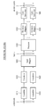
도 14는 본 발명의 실시 예가 적용될 수 있는 전송 자원이 선택되는 예를 나타낸다.14 shows an example in which a transmission resource to which an embodiment of the present invention can be applied is selected.
도 14를 참조하면, 단말은 센싱 윈도우 내에서 센싱을 통해 다른 단말이 예약한 전송 자원들 또는 다른 단말이 사용하고 있는 자원들을 파악할 수 있고, 선택 윈도우 내에서 이를 배제한 후, 남아 있는 자원들 중 간섭이 적은 자원에서 랜덤하게 자원을 선택할 수 있다. Referring to FIG. 14, a terminal can identify transmission resources reserved by another terminal or resources used by another terminal through sensing within a sensing window, and after excluding it in a selection window, interference among remaining resources The resource can be randomly selected from this small resource.
예를 들어, 단말은 센싱 윈도우 내에서, 예약된 자원들의 주기에 대한 정보를 포함하는 PSCCH를 디코딩하고, 상기 PSCCH를 기반으로 주기적으로 결정된 자원들에서 PSSCH RSRP를 측정할 수 있다. 단말은 상기 PSSCH RSRP 값이 임계치를 초과하는 자원들을 선택 윈도우 내에서 제외할 수 있다. 그 후, 단말은 선택 윈도우 내의 남은 자원들 중에서 사이드링크 자원을 랜덤하게 선택할 수 있다. For example, within the sensing window, the UE may decode a PSCCH including information on a period of reserved resources, and measure PSSCH RSRP from resources periodically determined based on the PSCCH. The UE may exclude resources in which the PSSCH RSRP value exceeds a threshold within a selection window. Thereafter, the terminal may randomly select the sidelink resource among the remaining resources in the selection window.
또는, 단말은 센싱 윈도우 내에서 주기적인 자원들의 RSSI(Received signal strength indication)를 측정하여 간섭이 적은 자원들(예를 들어, 하위 20%에 해당하는 자원들)을 결정할 수 있다. 그리고, 단말은 상기 주기적인 자원들 중 선택 윈도우에 포함된 자원들 중에서 사이드링크 자원을 랜덤하게 선택할 수도 있다. 예를 들어, 단말이 PSCCH의 디코딩을 실패한 경우, 단말은 위와 같은 방법을 사용할 수 있다.Alternatively, the terminal may determine the resources with low interference (for example, resources corresponding to the lower 20%) by measuring the received signal strength indication (RSSI) of periodic resources in the sensing window. And, the terminal may randomly select a sidelink resource from among the resources included in the selection window among the periodic resources. For example, when the UE fails to decode the PSCCH, the UE may use the above method.
이하, 사이드링크 혼잡 제어(sidelink congestion control)에 대하여 설명한다.Hereinafter, sidelink congestion control will be described.
단말이 사이드링크 전송 자원을 스스로 결정하는 경우, 단말은 자신이 사용하는 자원의 크기 및 빈도 역시 스스로 결정하게 된다. 물론, 네트워크 등으로부터의 제약 조건으로 인하여, 일정 수준 이상의 자원 크기나 빈도를 사용하는 것은 제한될 수 있다. 그러나, 특정 시점에 특정 지역에 많은 단말이 몰려 있는 상황에서 모든 단말들이 상대적으로 많은 자원을 사용하는 경우라면, 상호 간에 간섭으로 인하여 전체적인 성능이 크게 저하될 수 있다.When the terminal determines the sidelink transmission resource itself, the terminal also determines the size and frequency of the resource it uses. Of course, due to constraints from the network or the like, the use of resource sizes or frequencies above a certain level may be restricted. However, if all terminals use relatively many resources in a situation where a large number of terminals are concentrated in a specific region at a specific time point, overall performance may be significantly deteriorated due to interference with each other.
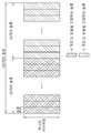
따라서, 단말은 채널 상황을 관찰할 필요가 있다. 만약 과도하게 많은 자원이 소모되고 있다고 판단되면, 단말은 스스로의 자원 사용을 줄이는 형태의 동작을 취하는 것이 바람직하다. 본 명세서에서, 이를 혼잡 제어(Congestion Control, CR)라고 정의할 수 있다. 예를 들어, 단말은 단위 시간/주파수 자원에서 측정된 에너지가 일정 수준 이상인지 여부를 판단하고, 일정 수준 이상의 에너지가 관찰된 단위 시간/주파수 자원의 비율에 따라서 자신의 전송 자원의 양 및 빈도를 조절할 수 있다. 본 명세서에서, 일정 수준 이상의 에너지가 관찰된 시간/주파수 자원의 비율을 채널 혼잡 비율(Channel Busy Ratio, CBR)이라고 정의할 수 있다. 단말은 채널/주파수에 대하여 CBR을 측정할 수 있다. 부가적으로, 단말은 측정된 CBR을 네트워크/기지국에게 전송할 수 있다.Therefore, the terminal needs to observe the channel condition. If it is determined that an excessive amount of resources is being consumed, it is preferable that the terminal takes a form of reducing its own resource use. In the present specification, this may be defined as congestion control (CR). For example, the UE determines whether the energy measured in the unit time / frequency resource is higher than a certain level, and determines the amount and frequency of its transmission resource according to the ratio of the unit time / frequency resource in which energy above a certain level is observed. Can be adjusted. In this specification, a ratio of time / frequency resources in which energy above a certain level is observed may be defined as a channel busy ratio (CBR). The UE can measure CBR for a channel / frequency. Additionally, the terminal may transmit the measured CBR to the network / base station.
도 15는 본 발명의 실시 예가 적용될 수 있는 CBR의 일 예를 나타낸다.15 shows an example of a CBR to which an embodiment of the present invention can be applied.
도 15를 참조하면, CBR은 단말이 100ms 동안 서브 채널 단위로 RSSI(Received Signal Strength Indicator)를 측정한 결과, RSSI의 측정 결과 값이 미리 설정된 임계치 이상의 값을 가지는 서브 채널의 개수를 의미할 수 있다. 또는, CBR은 특정 구간 동안의 서브 채널 중 미리 설정된 임계치 이상의 값을 가지는 서브 채널의 비율을 의미할 수 있다. 예를 들어, 도 15의 실시 예에서, 빗금 쳐진 서브 채널이 미리 설정된 임계치 이상의 값을 가지는 서브 채널이라고 가정하는 경우, CBR은 100ms 구간 동안 빗금 쳐진 서브 채널의 비율을 의미할 수 있다.Referring to FIG. 15, the CBR may mean the number of sub-channels in which the result of the measurement of the RSSI has a value greater than or equal to a preset threshold, as a result of the UE measuring the received signal strength indicator (RSSI) in sub-channel units for 100 ms. . Alternatively, CBR may refer to a ratio of sub-channels having a value equal to or greater than a preset threshold among sub-channels during a specific period. For example, in the embodiment of FIG. 15, when it is assumed that the hatched sub-channel is a sub-channel having a value equal to or greater than a preset threshold, CBR may mean the ratio of the hatched sub-channel during a 100 ms interval.
나아가, 트래픽(예를 들어, 패킷)의 우선 순위를 고려한 혼잡 제어가 필요할 수 있다. 구체적으로, 각 단말은 CBR을 측정하고, CBR에 따라 각 트래픽 우선 순위(예를 들어, k)가 점유할 수 있는 채널 사용율(channel occupancy ratio k; CRk)의 최대값(CRlimitk)을 결정한다. 예를 들어, 단말은 CBR 측정값과 미리 정해진 표를 기반으로 각 트래픽의 우선 순위에 대한 채널 사용율의 최대값(CRlimitk)을 도출할 수 있다. 상대적으로 우선 순위가 높은 트래픽의 경우 더 큰 채널 사용율의 최대값이 도출될 수 있다. 그 후, 단말은 트래픽의 우선 순위 k가 i보다 낮은 트래픽들의 채널 사용율의 총합을 일정 값 이하로 제한함으로써, 혼잡 제어를 수행할 수 있다. 이러한 방법에 의하면, 상대적으로 우선 순위가 낮은 트래픽들에 더 강한 채널 사용율 제한이 걸리게 될 수 있다. Furthermore, congestion control considering the priority of traffic (eg, packets) may be required. Specifically, each UE measures the CBR, and determines a maximum value (CRlimitk) of a channel occupancy ratio k (CRk) that can be occupied by each traffic priority (eg, k) according to the CBR. For example, the terminal may derive a maximum value (CRlimitk) of the channel utilization rate for each traffic priority based on the CBR measurement value and a predetermined table. For relatively high-priority traffic, a maximum value of a larger channel usage rate may be derived. Thereafter, the UE can perform congestion control by limiting the sum of the channel usage rates of traffics having a priority k lower than i to a predetermined value or less. According to this method, stronger channel usage restrictions may be imposed on relatively low-priority traffic.
그 이외에, 단말은 전송 전력의 크기 조절, 패킷의 드롭(drop), 재전송 여부의 결정, 전송 RB 크기 조절(MCS 조정) 등의 방법을 이용하여, 사이드링크 혼잡 제어를 수행할 수 있다.In addition, the UE may perform sidelink congestion control using methods such as size adjustment of transmission power, drop of packets, determination of retransmission, and size adjustment of transmission RB (MCS adjustment).
한편, NR 시스템에서, 단말은 슬롯 포맷에 대한 정보를 수신할 수 있다. 예를 들어, 인-커버리지 단말은 서브캐리어 스페이싱(Subcarrier Spacing) 및 TDD DL/UL 패턴을 기지국으로부터 수신할 수 있다. 예를 들어, 상기 TDD DL UL 패턴은 DL/UL 전송 주기, 연속하는 DL 슬롯의 개수, 연속하는 DL 심볼의 개수, 연속하는 UL 슬롯의 개수 및 연속하는 UL 심볼의 개수를 포함할 수 있다. 이 경우, 단말은 상기 슬롯 포맷에 대한 정보를 기반으로 슬롯 포맷이 도 16과 같음을 알 수 있다.Meanwhile, in the NR system, the terminal may receive information on the slot format. For example, the in-coverage terminal may receive subcarrier spacing and TDD DL / UL patterns from the base station. For example, the TDD DL UL pattern may include a DL / UL transmission period, the number of consecutive DL slots, the number of consecutive DL symbols, the number of consecutive UL slots, and the number of consecutive UL symbols. In this case, the terminal can know that the slot format is the same as FIG. 16 based on the information on the slot format.
도 16은 본 발명의 실시 예가 적용될 수 있는 슬롯 포맷의 일 예를 나타낸다.16 shows an example of a slot format to which an embodiment of the present invention can be applied.
도 16의 실시 예와 같이, NR 시스템의 경우, 유연한 슬롯 포맷(flexible slot format)이 설정될 수 있다. 따라서, 예를 들어, NR 시스템의 경우, 슬롯 내 UL/DL/FLEXIBLE 자원을 각각 구성하는 심볼 개수가 슬롯 또는 BWP 사이에 일부 또는 전부 상이하게 설정될 수 있다. As in the embodiment of FIG. 16, in the case of an NR system, a flexible slot format may be set. Thus, for example, in the case of an NR system, the number of symbols constituting each UL / DL / FLEXIBLE resource in a slot may be set to be partially or entirely different between slots or BWPs.
따라서, 예를 들어, 인-커버리지 환경 하에서, V2X 자원 풀이 (일부) UL 자원에 대하여 설정되는 경우, (V2X 자원 풀을 구성하는) SL 슬롯 내의 심볼 개수는 슬롯 간에 상이할 수 있다. 또한, 예를 들어, 아웃-커버리지 환경 등에서 V2X 자원 풀이 설정되는 경우, SL 슬롯 내의 심볼 개수는 슬롯 간에 상이할 수 있다. 예를 들어, 아웃-커버리지 환경 등에서 UL 자원에 대한 고려 없이 V2X 자원 풀이 설정되는 경우, SL 슬롯 내의 심볼 개수는 슬롯 간에 상이할 수 있다. 이와 같은 경우, 예를 들어, 단말 간에 어떤 SL 슬롯이 선택되는지에 따라, 단말이 하나의 서브 채널을 사용하더라도 (실제) 이용하는 자원 양은 상이할 수 있다.Thus, for example, in an in-coverage environment, when a V2X resource pool is set for (some) UL resources, the number of symbols in the SL slot (constituting the V2X resource pool) may be different between slots. In addition, for example, when a V2X resource pool is configured in an out-coverage environment, the number of symbols in the SL slot may be different between slots. For example, when a V2X resource pool is configured without considering UL resources in an out-coverage environment, the number of symbols in the SL slot may be different between slots. In this case, for example, depending on which SL slot is selected between terminals, even if the terminal uses one sub-channel, the amount of resources (actually) used may be different.
본 명세서에서, SL 슬롯은, 단말이 사이드링크 통신을 수행할 수 있는 슬롯, 단말이 V2X 통신을 수행할 수 있는 슬롯, 사이드링크를 위한 자원 풀이 구성된 슬롯, 및/또는 V2X를 위한 자원 풀이 구성된 슬롯 중 적어도 어느 하나를 포함할 수 있다. 본 명세서에서, SL 심볼은 단말이 사이드링크 통신을 수행할 수 있는 슬롯, 단말이 V2X 통신을 수행할 수 있는 슬롯, 사이드링크 통신과 관련된 심볼, 및/또는 사이드링크와 관련된 심볼 중 적어도 어느 하나를 포함할 수 있다. 예를 들어, SL 심볼은 UL 심볼 및/또는 FLEXIBLE (F) 심볼 중 적어도 어느 하나를 포함할 수 있다.In the present specification, the SL slot is a slot in which the terminal can perform sidelink communication, a slot in which the terminal can perform V2X communication, a slot in which a resource pool for sidelink is configured, and / or a slot in which a resource pool for V2X is configured It may include at least any one of. In the present specification, the SL symbol is at least one of a slot in which a terminal can perform sidelink communication, a slot in which a terminal can perform V2X communication, a symbol related to sidelink communication, and / or a symbol related to sidelink It can contain. For example, the SL symbol may include at least one of a UL symbol and / or a FLEXIBLE (F) symbol.
예를 들어, 전송 메시지 관련 서비스 타입, 요구 사항(예를 들어, 신뢰성 및/또는 지연), 타겟 커버리지, 및/또는 전송 채널 관련 파형(waveform) 등을 고려하여, 복수의 전송 단말이 각각 SL 슬롯 내 심볼의 개수(예를 들어, 전송 심볼의 개수 또는 SL 심볼의 개수)를 선택 및/또는 조절하는 경우, 복수의 전송 단말이 (동일한) SL 슬롯 내에서 각각 하나의 서브 채널을 사용하더라도, 복수의 단말에 의해 (실제) 사용되는 자원의 양은 복수의 단말 사이에서 상이할 수 있다.For example, considering transmission service-related service types, requirements (for example, reliability and / or delay), target coverage, and / or transmission channel-related waveforms, a plurality of transmission terminals are each SL slots. When selecting and / or adjusting the number of symbols (for example, the number of transmission symbols or the number of SL symbols), even if a plurality of transmitting terminals each use one sub-channel within the (same) SL slot, multiple The amount of resources (actually) used by the terminals of the may be different between the plurality of terminals.
예를 들어, 전송 메시지 관련 서비스 타입, 요구 사항, 타겟 커버리지, 및/또는 전송 채널 관련 파형 등을 고려하여, 복수의 전송 단말이 뉴머놀로지(예를 들어, 서브캐리어 스페이싱)를 선택하는 경우, 주어진 시간(예를 들어, 1 ms) 내에서 복수의 단말에 의해 수행되는 전송 횟수는 복수의 단말 사이에서 상이할 수 있다. 또는, 예를 들어, 전송 메시지 관련 서비스 타입, 요구 사항, 타겟 커버리지, 및/또는 전송 채널 관련 파형 등을 고려하여, 복수의 전송 단말이 뉴머놀로지(예를 들어, 서브캐리어 스페이싱)를 선택하는 경우, 주어진 시간(예를 들어, 1 ms) 내에서 복수의 단말에 의해 사용되는 자원의 양은 복수의 단말 사이에서 상이할 수 있다.For example, in consideration of a service type related to a transmission message, requirements, target coverage, and / or a waveform related to a transmission channel, a plurality of transmission terminals select a new technology (eg, subcarrier spacing), given The number of transmissions performed by a plurality of terminals within a time (eg, 1 ms) may be different between the plurality of terminals. Or, for example, in consideration of a service type related to a transmission message, requirements, target coverage, and / or a waveform related to a transmission channel, etc., when a plurality of transmission terminals select a new technology (eg, subcarrier spacing) , The amount of resources used by a plurality of terminals within a given time (eg, 1 ms) may be different between the plurality of terminals.
상술한 바와 같이, 복수의 단말이 SL 슬롯 내에서 또는 동일한 SL 슬롯 내에서 하나의 서브 채널을 사용하더라도, 복수의 단말에 의해 사용되는 자원의 양, 주어진 시간 내에서 복수의 단말에 의해 수행되는 전송 횟수, 및/또는 주어진 시간 내에서 복수의 단말에 의해 사용되는 자원의 양은 복수의 단말 사이에서 상이할 수 있다. 따라서, 상기 복수의 단말 측면에서, CR 측정 및/또는 CBR 측정을 공정하게 또는 효율적으로 수행하도록 하는 방법이 필요할 수 있다. As described above, even if a plurality of terminals use one sub-channel within an SL slot or within the same SL slot, the amount of resources used by the plurality of terminals, the transmission performed by the plurality of terminals within a given time The number of times and / or the amount of resources used by the plurality of terminals within a given time may be different between the plurality of terminals. Accordingly, in the plurality of terminal aspects, a method for performing CR measurement and / or CBR measurement fairly or efficiently may be necessary.
이하, 본 발명의 일 실시 예에 따라, 단말이 자원 단위(resource unit)를 기반으로 CR 측정 및/또는 CBR 측정을 수행하는 방법 및 이를 지원하는 장치에 대하여 설명한다.Hereinafter, a method for performing CR measurement and / or CBR measurement based on a resource unit and a device supporting the same according to an embodiment of the present invention will be described.
본 명세서에서, 사이드링크 RSSI(S-RSSI)는 서브프레임의 첫 번째 슬롯의 1, 2, ..., 6 SC-FDMA 심볼들 및 두 번째 슬롯의 0, 1, ..., 5 SC-FDMA에서 설정된 서브 채널에서만 단말에 의해 관측된 SC-FDMA 당 전체 수신된 전력([W] 단위)의 선형 평균(linear average)으로 정의될 수 있다(Sidelink RSSI (S-RSSI) may be defined as the linear average of the total received power (in [W]) per SC-FDMA symbol observed by the UE only in the configured sub-channel in SC-FDMA symbols 1, 2, ..., 6 of the first slot and SC-FDMA symbols 0,1,..., 5 of the second slot of a subframe). 본 명세서에서, PSSCH-RSRP는 관련된 PSCCH에 의해 지시된 PRB들 내에서, PSSCH와 관련된 복조 기준 신호를 운반하는 자원 요소의 전력 기여분([W] 단위)에 대한 선형 평균으로 정의될 수 있다(PSSCH Reference Signal Received Power (PSSCH-RSRP) may be defined as the linear average over the power contributions (in [W]) of the resource elements that carry demodulation reference signals associated with PSSCH, within the PRBs indicated by the associated PSCCH).In this specification, the sidelink RSSI (S-RSSI) is 1, 2, ..., 6 SC-FDMA symbols of the first slot of the subframe and 0, 1, ..., 5 SC- of the second slot It may be defined as a linear average of the total received power (in [W]) per SC-FDMA observed by the UE only in a subchannel set in FDMA (Sidelink RSSI (S-RSSI)) may be defined as the linear average of the total received power (in [W]) per SC-FDMA symbol observed by the UE only in the configured sub-channel in SC-
본 명세서에서, 단말의 수신 동작은 사이드링크 채널 및/또는 사이드링크 신호(예를 들어, PSCCH, PSSCH, PSFCH, PSBCH, PSSS/SSSS 등)의 디코딩 동작 및/또는 수신 동작을 포함할 수 있다. 단말의 수신 동작은 WAN DL 채널 및/또는 WAN DL 신호(예를 들어, PDCCH, PDSCH, PSS/SSS 등)의 디코딩 동작 및/또는 수신 동작을 포함할 수 있다. 단말의 수신 동작은 센싱 동작 및/또는 CBR 측정 동작을 포함할 수 있다. 본 명세서에서, 단말의 센싱 동작은 PSSCH DM-RS 시퀀스 기반의 PSSCH-RSRP 측정 동작, 단말이 성공적으로 디코딩한 PSCCH에 의해 스케줄링되는 PSSCH DM-RS 시퀀스 기반의 PSSCH-RSRP 측정 동작, S-RSSI(sidelink RSSI) 측정 동작, 및/또는 V2X 자원 풀 관련 서브 채널 기반의 S-RSSI 측정 동작을 포함할 수 있다. 본 명세서에서, 단말의 전송 동작은 사이드링크 채널 및/또는 사이드링크 신호(예를 들어, PSCCH, PSSCH, PSFCH, PSBCH, PSSS/SSSS 등)의 전송 동작을 포함할 수 있다. 단말의 전송 동작은 WAN UL 채널 및/또는 WAN UL 신호(예를 들어, PUSCH, PUCCH, SRS 등)의 전송 동작을 포함할 수 있다. 본 명세서에서, 동기 신호는 SLSS 및/또는 PSBCH를 포함할 수 있다.In this specification, the reception operation of the terminal may include a decoding operation and / or a reception operation of a sidelink channel and / or a sidelink signal (eg, PSCCH, PSSCH, PSFCH, PSBCH, PSSS / SSSS, etc.). The receiving operation of the terminal may include decoding and / or receiving operations of a WAN DL channel and / or a WAN DL signal (eg, PDCCH, PDSCH, PSS / SSS, etc.). The receiving operation of the terminal may include a sensing operation and / or a CBR measurement operation. In this specification, the sensing operation of the terminal is PSSCH DM-RS sequence-based PSSCH-RSRP measurement operation, the PSSCH DM-RS sequence-based PSSCH-RSRP measurement operation scheduled by the PSCCH successfully decoded by the terminal, S-RSSI ( sidelink RSSI) measurement operation, and / or V2X resource pool related sub-channel based S-RSSI measurement operation. In this specification, the transmission operation of the terminal may include a transmission operation of a sidelink channel and / or sidelink signal (eg, PSCCH, PSSCH, PSFCH, PSBCH, PSSS / SSSS, etc.). The transmission operation of the terminal may include a transmission operation of a WAN UL channel and / or a WAN UL signal (eg, PUSCH, PUCCH, SRS, etc.). In this specification, the synchronization signal may include SLSS and / or PSBCH.
본 명세서에서, 설정은 시그널링, 네트워크로부터의 시그널링, 네트워크로부터의 설정, 및/또는 네트워크로부터 미리 설정을 포함할 수 있다. 본 명세서에서, 정의는 시그널링, 네트워크로부터의 시그널링, 네트워크로부터의 설정, 및/또는 네트워크로부터 미리 설정을 포함할 수 있다. 본 명세서에서, 지정은 시그널링, 네트워크로부터의 시그널링, 네트워크로부터의 설정, 및/또는 네트워크로부터 미리 설정을 포함할 수 있다. 본 명세서에서, PPPP는 PPPR로 대체될 수 있으며, PPPR은 PPPP로 대체될 수 있다. 본 명세서에서, PPPP 값이 작을수록 높은 우선 순위를 의미할 수 있고, PPPP 값이 클수록 낮은 우선 순위를 의미할 수 있다. 본 명세서에서, PPPR 값이 작을수록 높은 신뢰성을 의미할 수 있고, PPPR 값이 클수록 낮은 신뢰성을 의미할 수 있다.In this specification, the settings may include signaling, signaling from the network, settings from the network, and / or presets from the network. In this specification, the definition may include signaling, signaling from the network, settings from the network, and / or presetting from the network. In this specification, the designation may include signaling, signaling from the network, settings from the network, and / or presetting from the network. In this specification, PPPP may be replaced with PPPR, and PPPR may be replaced with PPPP. In this specification, a smaller PPPP value may mean a higher priority, and a larger PPPP value may mean a lower priority. In this specification, a smaller PPPR value may mean higher reliability, and a larger PPPR value may mean lower reliability.
본 명세서에서 제안된 방법의 일부 또는 전부는 단말의 전송 동작, 전송 캐리어 선택 동작, 및/또는 전송 BWP 선택 동작에 한정될 수 있다. 또는, 예를 들어, 본 명세서에서 제안된 방법의 일부 또는 전부는 단말의 수신 동작, 수신 캐리어 선택 동작, 및/또는 수신 BWP 선택 동작에 한정될 수 있다. Some or all of the methods proposed in this specification may be limited to a transmission operation of a terminal, a transmission carrier selection operation, and / or a transmission BWP selection operation. Or, for example, some or all of the methods proposed in this specification may be limited to a reception operation of a terminal, a reception carrier selection operation, and / or a reception BWP selection operation.
본 명세서에서 제안된 적어도 하나의 제안 방식은, PC5 인터페이스 또는 SL 인터페이스(예를 들어, PSCCH, PSSCH, PSBCH, PSSS/SSSS 등) 기반의 사이드링크 통신 또는 V2X 통신뿐만 아니라, Uu 인터페이스(예를 들어, PUSCH, PDSCH, PDCCH, PUCCH 등) 기반의 사이드링크 통신 또는 V2X 통신에도, 적용될 수 있다.At least one proposed method proposed in the present specification is a PC5 interface or a SL interface (eg, PSCCH, PSSCH, PSBCH, PSSS / SSSS, etc.) based sidelink communication or V2X communication, as well as a Uu interface (eg , PUSCH, PDSCH, PDCCH, PUCCH, etc.)-Based sidelink communication or V2X communication.
도 17은 본 발명의 일 실시 예에 따라, 단말이 기본 자원 단위(basic resource unit)를 기반으로 CR 측정 또는 CBR 측정을 수행하는 방법을 나타낸다.17 shows a method of performing CR measurement or CBR measurement based on a basic resource unit, according to an embodiment of the present invention.
도 17을 참조하면, 단계 S1710에서, 단말은 기본 자원 단위에 대한 설정을 네트워크(예를 들어, 기지국)로부터 수신할 수 있다. 예를 들어, 상기 기본 자원 단위는 단말에 대하여 설정되거나, 사전에 설정될 수 있다. 예를 들어, 상기 기본 자원 단위는 CR 측정 및/또는 CBR 측정에 사용될 수 있다. 예를 들어, 상기 기본 자원 단위는 시간 및/또는 주파수 단위로 구성될 수 있다. 예를 들어, 상기 기본 자원 단위는 하나 이상의 심볼 및 하나 이상의 서브캐리어를 포함할 수 있다. 또는, 예를 들어, CR 측정 및/또는 CBR 측정에 사용될 기본 자원 단위 및/또는 기본 뉴머놀로지(예를 들어, 서브캐리어 스페이싱)는 단말에 대하여 설정되거나, 미리 설정될 수 있다. 또는, 예를 들어, CR 측정 및/또는 CBR 측정에 사용될 기본 자원 단위 및/또는 기본 뉴머놀로지(예를 들어, 서브캐리어 스페이싱)는 단말에 대하여 미리 정의될 수 있다.Referring to FIG. 17, in step S1710, the terminal may receive a setting for a basic resource unit from a network (eg, a base station). For example, the basic resource unit may be set for the terminal or may be set in advance. For example, the basic resource unit may be used for CR measurement and / or CBR measurement. For example, the basic resource unit may consist of time and / or frequency units. For example, the basic resource unit may include one or more symbols and one or more subcarriers. Or, for example, a basic resource unit and / or basic neuronism (eg, subcarrier spacing) to be used for CR measurement and / or CBR measurement may be set for a terminal or may be set in advance. Or, for example, a basic resource unit and / or basic neuronism (eg, subcarrier spacing) to be used for CR measurement and / or CBR measurement may be predefined for the UE.
본 명세서에서, 설명의 편의를 위해, 상기 기본 자원 단위 및/또는 기본 뉴머놀로지는 BASIC_CUN이라고 칭할 수 있다. 여기서, 예를 들어, BASIC_CUN은 V2X 자원 풀, BWP, 서비스 타입, PPPP, PPPR, 및/또는 뉴머놀로지에 따라 독립적으로 또는 상이하게 설정될 수 있다.In this specification, for convenience of description, the basic resource unit and / or basic neuronology may be referred to as BASIC_CUN. Here, for example, BASIC_CUN may be set independently or differently according to the V2X resource pool, BWP, service type, PPPP, PPPR, and / or numerology.
도 18은 본 발명의 일 실시 예에 따른 기본 자원 단위의 일 예를 나타낸다.18 shows an example of a basic resource unit according to an embodiment of the present invention.
도 18의 (a)를 참조하면, BASIC_CUN은 7 개의 심볼로 구성된 하나의 서브채널로 설정될 수 있다. 예를 들어, BASIC_CUN은 7 개의 심볼을 포함하는 하나의 서브채널로 설정될 수 있다. 도 18의 (b)를 참조하면, BASIC_CUN은 4 개의 심볼로 구성된 하나의 서브채널로 설정될 수 있다. 예를 들어, BASIC_CUN은 4 개의 심볼을 포함하는 하나의 서브채널로 설정될 수 있다. 도 18의 (c)를 참조하면, BASIC_CUN은 7 개의 심볼로 구성된 두 개의 서브채널로 설정될 수 있다. 예를 들어, BASIC_CUN은 7 개의 심볼을 포함하는 두 개의 서브채널로 설정될 수 있다. 도 18의 (d)를 참조하면, BASIC_CUN은 6 개의 심볼로 구성된 세 개의 서브채널로 설정될 수 있다. 예를 들어, BASIC_CUN은 6 개의 심볼을 포함하는 세 개의 서브채널로 설정될 수 있다. 도 18의 실시 예는 일 예에 불과하며, BASIC_CUN은 다양한 방법에 의해 설정 또는 정의될 수 있다.Referring to (a) of FIG. 18, BASIC_CUN may be configured as one subchannel composed of 7 symbols. For example, BASIC_CUN may be configured as one subchannel including 7 symbols. Referring to (b) of FIG. 18, BASIC_CUN may be configured as one subchannel composed of 4 symbols. For example, BASIC_CUN may be set to one subchannel including four symbols. Referring to (c) of FIG. 18, BASIC_CUN may be set to two subchannels composed of seven symbols. For example, BASIC_CUN may be set to two subchannels including 7 symbols. Referring to (d) of FIG. 18, BASIC_CUN may be set to three subchannels composed of six symbols. For example, BASIC_CUN may be set to three subchannels including six symbols. The embodiment of FIG. 18 is only an example, and BASIC_CUN may be set or defined by various methods.
예를 들어, BASIC_CUN은 V2X 자원 풀 내에서 SL 전송을 위해 선택될 수 있는 가장 작은 양의 (시간 및/또는 주파수) 자원 단위로 설정될 수 있다. 예를 들어, BASIC_CUN은 V2X 자원 풀 내에서 SL 전송을 위해 선택될 수 있는 가장 많은 양의 (시간 및/또는 주파수) 자원 단위로 설정될 수 있다. For example, BASIC_CUN may be set in the smallest amount of (time and / or frequency) resource units that can be selected for SL transmission within the V2X resource pool. For example, BASIC_CUN may be set in the largest amount of (time and / or frequency) resource units that can be selected for SL transmission within the V2X resource pool.
예를 들어, BASIC_CUN은 V2X 자원 풀 내에서 SL 전송을 위해 선택될 수 있는 가장 작은 양의 (시간 및/또는 주파수) 자원 단위 및/또는 가장 큰 뉴머놀로지(예를 들어, 서브캐리어 스페이싱)로 설정될 수 있다. 예를 들어, BASIC_CUN은 V2X 자원 풀 내에서 SL 전송을 위해 선택될 수 있는 가장 작은 양의 (시간 및/또는 주파수) 자원 단위 및/또는 가장 작은 뉴머놀로지(예를 들어, 서브캐리어 스페이싱)로 설정될 수 있다. 예를 들어, BASIC_CUN은 V2X 자원 풀 내에서 SL 전송을 위해 선택될 수 있는 가장 많은 양의 (시간 및/또는 주파수) 자원 단위 및/또는 가장 큰 뉴머놀로지(예를 들어, 서브캐리어 스페이싱)로 설정될 수 있다. 예를 들어, BASIC_CUN은 V2X 자원 풀 내에서 SL 전송을 위해 선택될 수 있는 가장 많은 양의 (시간 및/또는 주파수) 자원 단위 및/또는 가장 작은 뉴머놀로지(예를 들어, 서브캐리어 스페이싱)로 설정될 수 있다.For example, BASIC_CUN is set to the smallest amount (time and / or frequency) resource units and / or largest numerology (e.g., subcarrier spacing) that can be selected for SL transmission within a V2X resource pool. Can be. For example, BASIC_CUN is set to the smallest amount (time and / or frequency) resource units and / or smallest numerology (e.g., subcarrier spacing) that can be selected for SL transmission within a V2X resource pool. Can be. For example, BASIC_CUN is set to the largest amount of (time and / or frequency) resource units and / or largest numerology (e.g., subcarrier spacing) that can be selected for SL transmission within a V2X resource pool. Can be. For example, BASIC_CUN is set to the largest amount of (time and / or frequency) resource units and / or smallest numerology (e.g., subcarrier spacing) that can be selected for SL transmission within a V2X resource pool. Can be.
예를 들어, BASIC_CUN은 최소 심볼 개수로 구성된 SL 슬롯 상의 서브 채널로 설정될 수 있다. 예를 들어, BASIC_CUN은 최대 심볼 개수로 구성된 SL 슬롯 상의 서브 채널로 설정될 수 있다. 예를 들어, BASIC_CUN은 최소 심볼 개수를 가지는 서브 채널로 설정될 수 있다. 예를 들어, BASIC_CUN은 최대 심볼 개수를 가지는 서브 채널로 설정될 수 있다.For example, BASIC_CUN may be set as a sub-channel on the SL slot composed of the minimum number of symbols. For example, BASIC_CUN may be set as a sub-channel on the SL slot composed of the maximum number of symbols. For example, BASIC_CUN may be set to a sub-channel having the minimum number of symbols. For example, BASIC_CUN may be set as a sub-channel having the maximum number of symbols.
예를 들어, BASIC_CUN은 (사전에 정의된 개수의) SL 슬롯 단위의 (주파수) 자원으로 설정될 수 있다. 여기서, 예를 들어, 해당 규칙이 적용될 경우, 상이한 심볼 개수를 가지는 SL 슬롯 간에 하나 이상의 서브 채널을 이용한 SL 전송, 또는 상이한 심볼 개수를 가지는 하나 이상의 서브 채널을 이용한 SL 전송이, CR 측정 및/또는 CBR 측정 측면에서 구분되지 않을 수 있다.For example, BASIC_CUN may be configured as a (frequency) resource of a SL slot unit (in a predefined number). Here, for example, when the corresponding rule is applied, SL transmission using one or more sub-channels between SL slots having different symbol numbers, or SL transmission using one or more sub-channels having different symbol numbers, CR measurement and / or It may not be distinguished in terms of CBR measurement.
도 19는 본 발명의 일 실시 예에 따라, 기본 자원 단위가 설정되는 예를 나타낸다.19 shows an example in which a basic resource unit is set according to an embodiment of the present invention.
도 19를 참조하면, V2X 자원 풀은 SL 슬롯 #N, SL 슬롯 #N + M 및 SL 슬롯 #N + M + L을 포함한다고 가정한다. 그리고, SL 슬롯 #N은 12 개의 SL 심볼을 포함하고, SL 슬롯 #N + M은 4 개의 SL 심볼을 포함하며, SL 슬롯 #N + M + L은 8 개의 사이드링크 심볼을 포함한다고 가정한다.Referring to FIG. 19, it is assumed that the V2X resource pool includes SL slot #N, SL slot #N + M and SL slot #N + M + L. In addition, it is assumed that SL slot #N includes 12 SL symbols, SL slot #N + M includes 4 SL symbols, and SL slot #N + M + L includes 8 sidelink symbols.
이 경우, 예를 들어, BASIC_CUN이 V2X 자원 풀 내에서 SL 전송을 위해 선택될 수 있는 가장 작은 양의 자원 단위로 설정되는 경우, BASIC_CUN은 가장 적은 개수의 SL 심볼을 가지는 슬롯을 기반으로 설정될 수 있다. 예를 들어, 도 19의 실시 예에서, SL 슬롯 #N + M을 기반으로, BASIC_CUN은 4 개의 심볼을 포함하는 하나 이상의 서브캐리어로 설정될 수 있다.In this case, for example, if BASIC_CUN is set to the smallest amount of resource units that can be selected for SL transmission within the V2X resource pool, BASIC_CUN can be set based on the slot with the smallest number of SL symbols. have. For example, in the embodiment of FIG. 19, based on SL slot #N + M, BASIC_CUN may be set to one or more subcarriers including four symbols.
또는, 예를 들어, BASIC_CUN이 V2X 자원 풀 내에서 SL 전송을 위해 선택될 수 있는 가장 많은 양의 자원 단위로 설정되는 경우, BASIC_CUN은 가장 많은 개수의 SL 심볼을 가지는 슬롯을 기반으로 설정될 수 있다. 예를 들어, 도 19의 실시 예에서, SL 슬롯 #N을 기반으로, BASIC_CUN은 12 개의 심볼을 포함하는 하나 이상의 서브캐리어로 설정될 수 있다.Or, for example, when BASIC_CUN is set to the largest amount of resource units that can be selected for SL transmission in the V2X resource pool, BASIC_CUN can be set based on the slot with the largest number of SL symbols. . For example, in the embodiment of FIG. 19, based on SL slot #N, BASIC_CUN may be set to one or more subcarriers including 12 symbols.
다시 도 17을 참조하면, 단계 S2020에서, 단말은 BASIC_CUN을 기반으로 CR 측정 및/또는 CBR 측정을 수행할 수 있다. 그리고, 단계 S2030에서, 단말은 사이드링크 전송을 수행할 수 있다. 예를 들어, 상기 사이드링크 전송은 CR 측정 및/또는 CBR 측정에 따라 선택 및/또는 점유된 자원을 이용하여 수행될 수 있다.Referring back to FIG. 17, in step S2020, the UE may perform CR measurement and / or CBR measurement based on BASIC_CUN. Then, in step S2030, the terminal may perform sidelink transmission. For example, the sidelink transmission may be performed using resources selected and / or occupied according to CR measurement and / or CBR measurement.
예를 들어, LTE V2X 또는 LTE SL의 경우, 단말은 서브프레임 단위로 CR 측정 및/또는 CBR 측정을 수행하였다. LTE의 경우, 하나의 서브프레임 전체가 사이드링크 통신을 위해 사용되었기 때문에, 단말이 서브프레임 단위로 CR 측정 및/또는 CBR 측정을 수행하여도 문제가 없었다. For example, in the case of LTE V2X or LTE SL, the UE has performed CR measurement and / or CBR measurement on a subframe basis. In the case of LTE, since one entire subframe is used for sidelink communication, there is no problem even when the UE performs CR measurement and / or CBR measurement in units of subframes.
하지만, NR V2X 또는 NR SL의 경우, 유연한 슬롯 포맷으로 인하여, 하나의 슬롯 내에서 전체 심볼이 아닌 일부 심볼만이 사이드링크 통신을 위해 사용될 수 있다. 하나의 슬롯 내에서 일부 심볼만이 사이드링크 통신을 위해 사용될 수 있음에도 불구하고, 복수의 단말이 슬롯을 구성하는 전체 심볼 단위로 CR 측정 및/또는 CBR 측정을 수행하는 것은 복수의 단말 사이에 불공평을 야기할 수 있다. 예를 들어, 제 1 단말이 제 1 슬롯에서 4 개의 심볼을 사이드링크 통신을 위해 사용할 수 있고, 제 2 단말이 제 2 슬롯에서 8 개의 심볼을 사이드링크 통신을 위해 사용할 수 있다고 가정한다. 이 경우, 제 1 단말 및 제 2 단말이 14 개의 심볼 단위로 CR 측정 및/또는 CBR 측정을 수행하면, 제 2 단말이 제 1 단말에 비하여 더 많은 자원을 이용하여 사이드링크 통신을 수행할 수 있음에도 불구하고, CR 측정 및/또는 CBR 측정은 동일한 기준으로 수행될 수 있다. 또는, 제 1 단말이 4 개의 심볼 단위로 CR 측정 및/또는 CBR 측정을 수행하고, 제 2 단말이 8 개의 심볼 단위로 CR 측정 및/또는 CBR 측정을 수행하면, 제 2 단말이 제 1 단말에 비하여 더 많은 자원을 이용하여 사이드링크 통신을 수행할 수 있음에도 불구하고, CR 측정 및/또는 CBR 측정은 동일한 기준으로 수행될 수 있다. 이는, 제 1 단말 측면에서, 불리하게 작용할 수 있다. However, in the case of NR V2X or NR SL, due to the flexible slot format, only some symbols, not all symbols, in one slot can be used for sidelink communication. Although only some symbols in one slot can be used for sidelink communication, it is unfair to perform CR measurement and / or CBR measurement in units of all symbols constituting a slot in a plurality of terminals. Can cause. For example, it is assumed that the first terminal can use four symbols in the first slot for sidelink communication, and the second terminal can use eight symbols in the second slot for sidelink communication. In this case, if the first terminal and the second terminal perform CR measurement and / or CBR measurement in units of 14 symbols, the second terminal can perform sidelink communication using more resources than the first terminal. Nevertheless, CR measurement and / or CBR measurement can be performed on the same criteria. Alternatively, if the first terminal performs CR measurement and / or CBR measurement in units of 4 symbols, and the second terminal performs CR measurement and / or CBR measurement in units of 8 symbols, the second terminal transmits to the first terminal. In comparison, CR measurement and / or CBR measurement may be performed based on the same criteria, although sidelink communication may be performed using more resources. This may adversely act on the first terminal side.
반면, 본 발명의 일 실시 예에 따르면, 단말은 CR 측정 및/또는 CBR 측정을 위한 BASIC_CUN을 설정 받을 수 있고, 단말은 BASIC_CUN을 기반으로 CR 측정 및/또는 CBR 측정을 수행할 수 있다. 예를 들어, 제 1 단말이 제 1 슬롯에서 4 개의 심볼을 사이드링크 통신을 위해 사용할 수 있고, 제 2 단말이 제 2 슬롯에서 8 개의 심볼을 사이드링크 통신을 위해 사용할 수 있다고 가정한다. 그리고, BASIC_CUN은 4 개의 심볼로 구성된 서브 채널이라고 가정한다. 이 경우, 예를 들어, 제 2 단말이 제 2 슬롯에서 8 개의 심볼을 점유하고, 제 1 단말이 제 1 슬롯에서 4 개의 심볼을 점유하면, 제 2 단말은 CR 측정 시 제 2 슬롯에서 자원을 두 번 점유한 것으로 간주하고, 제 1 단말은 CR 측정 시 제 1 슬롯에서 자원을 한 번 점유한 것으로 간주한다. 따라서, BASIC_CUN을 기반으로 CR 측정 및/또는 CBR 측정을 수행하는 경우, 유연한 슬롯 포맷으로 인하여, 복수의 SL 슬롯을 구성하는 SL 심볼의 개수가 상이하더라도, 단말은 BASIC_CUN을 기반으로 CR 측정 및/또는 CBR 측정을 공정하게 또는 효율적으로 수행할 수 있다. On the other hand, according to an embodiment of the present invention, the terminal may be configured with BASIC_CUN for CR measurement and / or CBR measurement, and the terminal may perform CR measurement and / or CBR measurement based on BASIC_CUN. For example, it is assumed that the first terminal can use four symbols in the first slot for sidelink communication, and the second terminal can use eight symbols in the second slot for sidelink communication. In addition, it is assumed that BASIC_CUN is a subchannel composed of 4 symbols. In this case, for example, if the second terminal occupies eight symbols in the second slot, and the first terminal occupies four symbols in the first slot, the second terminal occupies resources in the second slot when CR is measured. It is regarded that it is occupied twice, and the first terminal is regarded as occupying the resource once in the first slot when CR is measured. Therefore, when performing CR measurement and / or CBR measurement based on BASIC_CUN, even if the number of SL symbols constituting a plurality of SL slots is different due to a flexible slot format, the terminal measures CR and / or CR based on BASIC_CUN. CBR measurements can be performed fairly or efficiently.
이하, 본 발명의 일 실시 예에 따라, 단말이 BASIC_CUN을 기반으로 CR 측정 및/또는 CBR 측정을 수행하는 방법을 구체적으로 설명한다. Hereinafter, a method of performing CR measurement and / or CBR measurement based on BASIC_CUN according to an embodiment of the present invention will be described in detail.
예를 들어, 단말이 CR 측정 및/또는 CBR 측정을 수행할 때, 단말은 RSCNM_SL을 BASIC_CUN으로 나눈 값 또는 RSCNM_SL을 BASIC_CUN으로 정규화한 값을 CR 측정 및/또는 CBR 측정에 반영할 수 있다. 여기서, RSCNM_SL은 SL 슬롯 내에서 사용되는 자원의 양, SL 슬롯 내에서 SL 전송을 위해 사용되는 자원의 양, 주어진 시간 내에서 수행되는 전송 횟수, 및/또는 주어진 시간 내에서 SL 전송을 위해 수행되는 전송 횟수 중 적어도 어느 하나를 포함할 수 있다. 여기서, 예를 들어, 해당 규칙이 적용될 경우, 상대적으로 많은 심볼 개수로 구성된 하나 이상의 서브 채널이, CR 및/또는 CBR 관점에서, 가중치가 높은 것으로 해석될 수 있다. 예를 들어, 해당 규칙이 적용될 경우, 상대적으로 많은 심볼 개수로 구성된 하나 이상의 서브 채널이, 상대적으로 적은 심벌 개수로 구성된 하나 이상의 서브 채널 대비, CR 및/또는 CBR 관점에서, 가중치가 상대적으로 높은 것으로 해석될 수 있다. For example, when the UE performs CR measurement and / or CBR measurement, the UE may reflect RSCNM_SL divided by BASIC_CUN or RSCNM_SL normalized by BASIC_CUN into CR measurement and / or CBR measurement. Here, RSCNM_SL is the amount of resources used in the SL slot, the amount of resources used for SL transmission in the SL slot, the number of transmissions performed within a given time, and / or performed for SL transmissions within a given time It may include at least one of the number of transmissions. Here, for example, when the corresponding rule is applied, one or more sub-channels composed of a relatively large number of symbols may be interpreted as having a high weight in terms of CR and / or CBR. For example, when the corresponding rule is applied, one or more sub-channels composed of a relatively large number of symbols, compared to one or more sub-channels composed of a relatively small number of symbols, have a relatively high weight in terms of CR and / or CBR. Can be interpreted.
도 20은 본 발명의 일 실시 예에 따라, 단말이 기본 자원 단위를 기반으로 CR 측정 및/또는 CBR 측정을 수행하는 일 예를 나타낸다.20 illustrates an example in which a terminal performs CR measurement and / or CBR measurement based on a basic resource unit according to an embodiment of the present invention.
설명의 편의를 위해, 도 20의 실시 예에서, BASIC_CUN은 하나 이상의 심볼 및 하나의 서브채널로 구성되는 것으로 가정한다. 다만, 본 발명의 기술적 사상이 이에 제한되는 것은 아니며, 도 18의 실시 예와 같이, BASIC_CUN은 하나 이상의 심볼 및 복수의 서브채널로 구성될 수도 있다. 또한, 도 20의 실시 예에서, SL 심볼이 4 개 포함되는 SL 슬롯이 50 개 존재하고, SL 심볼이 2 개 포함되는 SL 슬롯이 50 개 존재하는 것으로 가정한다.For convenience of description, in the embodiment of FIG. 20, it is assumed that BASIC_CUN is composed of one or more symbols and one subchannel. However, the technical spirit of the present invention is not limited thereto, and as in the embodiment of FIG. 18, BASIC_CUN may be composed of one or more symbols and a plurality of subchannels. In addition, in the embodiment of FIG. 20, it is assumed that 50 SL slots including 4 SL symbols and 50 SL slots including 2 SL symbols exist.
1) CR 측정의 경우1) CR measurement
제 1 단말은 4 개의 SL 심볼을 포함하는 SL 슬롯을 10개 점유한다고 가정하고, 제 2 단말은 2 개의 SL 심볼을 포함하는 SL 슬롯을 10개 점유한다고 가정한다. It is assumed that the first terminal occupies 10 SL slots containing 4 SL symbols, and the second terminal assumes 10 SL slots containing 2 SL symbols.
예를 들어, 단말이 CR 값을 계산할 때, 분모의 값은 BASIC_CUN을 구성하는 심볼의 개수에 따라 변경될 수 있다. 예를 들어, 제 1 단말이 2 개의 심볼 및 하나의 서브 채널로 구성된 BASIC_CUN을 기반으로 CR 값을 계산하는 경우, CR 값은 13.33% (= 20 / 150)로 획득될 수 있다. 예를 들어, 제 2 단말이 2 개의 심볼 및 하나의 서브 채널로 구성된 BASIC_CUN을 기반으로 CR 값을 계산하는 경우, CR 값은 6.67% (= 10 / 150)로 획득될 수 있다. 예를 들어, BASIC_CUN이 2 개의 심볼로 구성된 서브 채널로 설정된 경우, 단말이 4 개의 심볼로 구성된 서브 채널을 사용하면, 단말이 2 개의 심볼로 구성된 서브 채널을 사용하는 것과 비교하여, CR 값은 2 배 증가할 수 있다. 이 경우, CR 측정의 정확도가 보다 향상될 수 있다.For example, when the terminal calculates the CR value, the denominator value may be changed according to the number of symbols constituting BASIC_CUN. For example, when the first terminal calculates the CR value based on BASIC_CUN composed of two symbols and one sub-channel, the CR value may be obtained as 13.33% (= 20/150). For example, when the second terminal calculates a CR value based on BASIC_CUN composed of two symbols and one sub-channel, the CR value may be obtained as 6.67% (= 10/150). For example, when BASIC_CUN is set to a sub-channel consisting of 2 symbols, when the terminal uses a sub-channel consisting of 4 symbols, compared to the terminal using a sub-channel consisting of 2 symbols, the CR value is 2 It can be doubled. In this case, the accuracy of the CR measurement can be further improved.
예를 들어, 단말이 CR 값을 계산할 때, 분모의 값은 BASIC_CUN을 구성하는 심볼의 개수와 무관하게, 실제 사이드링크 전송에 사용될 수 있는 서브 채널의 개수에 따라 결정될 수 있다. 예를 들어, 제 1 단말이 4 개의 심볼 및 하나의 서브 채널로 구성된 BASIC_CUN과 사이드링크와 관련된 서브 채널의 개수를 기준으로 CR 값을 계산하는 경우, CR 값은 10% (= 10 / 100)로 획득될 수 있다. 예를 들어, 제 2 단말이 4 개의 심볼 및 하나의 서브 채널로 구성된 BASIC_CUN과 사이드링크와 관련된 서브 채널의 개수를 기준으로 CR 값을 계산하는 경우, CR 값은 10% (= 10 / 100)로 획득될 수 있다. 이 경우, 단말 구현의 복잡도가 CR 측정시 감소될 수 있다.For example, when the terminal calculates the CR value, the value of the denominator can be determined according to the number of subchannels that can be actually used for sidelink transmission, regardless of the number of symbols constituting BASIC_CUN. For example, when the first terminal calculates the CR value based on the number of sub-channels related to the sidelink and BASIC_CUN composed of 4 symbols and one sub-channel, the CR value is 10% (= 10/100). Can be obtained. For example, when the second terminal calculates the CR value based on the number of BASIC_CUN composed of 4 symbols and one subchannel and the number of subchannels related to the sidelink, the CR value is 10% (= 10/100). Can be obtained. In this case, the complexity of the terminal implementation may be reduced when measuring CR.
2) CBR 측정의 경우2) For CBR measurement
2.1) 예를 들어, SL 심볼 4개를 포함하는 50 개의 SL 슬롯에서 측정된 RSSI 값이 임계값을 초과한다고 가정한다.2.1) For example, assume that the RSSI value measured in 50 SL slots including 4 SL symbols exceeds a threshold value.
예를 들어, 단말이 2 개의 심볼 및 하나의 서브 채널로 구성된 BASIC_CUN을 기반으로 CBR 값을 계산하는 경우, CBR 값은 75% (= 100 / 150)로 획득될 수 있다. 또는, 예를 들어, 단말이 4 개의 심볼 및 하나의 서브 채널로 구성된 BASIC_CUN을 기반으로 CBR 값을 계산하는 경우, CBR 값은 50% (= 50 / 100)로 획득될 수 있다. 이 경우, 단말이 CBR 값을 계산할 때, 분모의 값은 BASIC_CUN을 구성하는 심볼의 개수에 따라 변경될 수 있다.For example, when the terminal calculates a CBR value based on BASIC_CUN composed of two symbols and one sub-channel, the CBR value may be obtained as 75% (= 100/150). Or, for example, when the terminal calculates the CBR value based on BASIC_CUN composed of 4 symbols and one sub-channel, the CBR value may be obtained as 50% (= 50/100). In this case, when the terminal calculates the CBR value, the denominator value may be changed according to the number of symbols constituting BASIC_CUN.
예를 들어, 단말이 2 개의 심볼 및 하나의 서브 채널로 구성된 BASIC_CUN과 사이드링크와 관련된 서브 채널의 개수를 기준으로 CBR 값을 계산하는 경우, CBR 값은 100% (= 100 / 100)로 획득될 수 있다. 또는, 예를 들어, 단말이 4 개의 심볼 및 하나의 서브 채널로 구성된 BASIC_CUN과 사이드링크와 관련된 서브 채널의 개수를 기준으로 CBR 값을 계산하는 경우, CBR 값은 50% (= 50 / 100)로 획득될 수 있다. 이 경우, 단말이 CBR 값을 계산할 때, 분모의 값은 BASIC_CUN을 구성하는 심볼의 개수와 무관하게, 실제 사이드링크 전송에 사용될 수 있는 서브 채널의 개수에 따라 결정될 수 있다.For example, when the terminal calculates the CBR value based on the number of BASIC_CUN composed of 2 symbols and one subchannel and the number of subchannels related to the sidelink, the CBR value may be obtained as 100% (= 100/100). You can. Or, for example, when the terminal calculates the CBR value based on the number of subchannels related to the sidelink and BASIC_CUN composed of 4 symbols and one subchannel, the CBR value is 50% (= 50/100). Can be obtained. In this case, when the UE calculates the CBR value, the denominator value may be determined according to the number of subchannels that can be actually used for sidelink transmission, regardless of the number of symbols constituting BASIC_CUN.
2.2) 예를 들어, SL 심볼 4개를 포함하는 25 개의 SL 슬롯에서 측정된 RSSI 값이 임계값을 초과하고, SL 심볼 2개를 포함하는 25 개의 SL 슬롯에서 측정된 RSSI 값이 임계값을 초과한다고 가정한다.2.2) For example, the RSSI value measured in 25 SL slots containing 4 SL symbols exceeds the threshold, and the RSSI value measured in 25 SL slots containing 2 SL symbols exceeds the threshold. Assume that.
예를 들어, 단말이 2 개의 심볼 및 하나의 서브 채널로 구성된 BASIC_CUN을 기반으로 CBR 값을 계산하는 경우, CBR 값은 50% (= 75 / 150)로 획득될 수 있다. 또는, 예를 들어, 단말이 4 개의 심볼 및 하나의 서브 채널로 구성된 BASIC_CUN을 기반으로 CBR 값을 계산하는 경우, CBR 값은 50% (= 50 / 100)로 획득될 수 있다. 이 경우, 단말이 CBR 값을 계산할 때, 분모의 값은 BASIC_CUN을 구성하는 심볼의 개수에 따라 변경될 수 있다.For example, when the terminal calculates a CBR value based on BASIC_CUN composed of two symbols and one sub-channel, the CBR value may be obtained as 50% (= 75/150). Or, for example, when the terminal calculates the CBR value based on BASIC_CUN composed of 4 symbols and one sub-channel, the CBR value may be obtained as 50% (= 50/100). In this case, when the terminal calculates the CBR value, the denominator value may be changed according to the number of symbols constituting BASIC_CUN.
예를 들어, 단말이 2 개의 심볼 및 하나의 서브 채널로 구성된 BASIC_CUN과 사이드링크와 관련된 서브 채널의 개수를 기준으로 CBR 값을 계산하는 경우, CBR 값은 75% (= 75 / 100)로 획득될 수 있다. 또는, 예를 들어, 단말이 4 개의 심볼 및 하나의 서브 채널로 구성된 BASIC_CUN과 사이드링크와 관련된 서브 채널의 개수를 기준으로 CBR 값을 계산하는 경우, CBR 값은 50% (= 50 / 100)로 획득될 수 있다. 이 경우, 단말이 CBR 값을 계산할 때, 분모의 값은 BASIC_CUN을 구성하는 심볼의 개수와 무관하게, 실제 사이드링크 전송에 사용될 수 있는 서브 채널의 개수에 따라 결정될 수 있다.For example, when the terminal calculates the CBR value based on the number of BASIC_CUN composed of 2 symbols and one subchannel and the number of subchannels related to the sidelink, the CBR value can be obtained as 75% (= 75/100). You can. Or, for example, when the terminal calculates the CBR value based on the number of subchannels related to the sidelink and BASIC_CUN composed of 4 symbols and one subchannel, the CBR value is 50% (= 50/100). Can be obtained. In this case, when the UE calculates the CBR value, the denominator value may be determined according to the number of subchannels that can be actually used for sidelink transmission, regardless of the number of symbols constituting BASIC_CUN.
예를 들어, 도 20의 실시 예에서, BASIC_CUN이 2 개의 심볼로 구성된 서브 채널로 설정된 경우, 단말이 4 개의 심볼로 구성된 서브 채널을 사용하면, 단말이 2 개의 심볼로 구성된 서브 채널을 사용하는 것과 비교하여, CBR 값은 증가할 수 있다.For example, in the embodiment of FIG. 20, when BASIC_CUN is set to a subchannel composed of two symbols, when the terminal uses a subchannel composed of four symbols, the terminal uses a subchannel composed of two symbols. In comparison, the CBR value can be increased.
본 발명의 일 실시 예에 따르면, 슬롯을 구성하는 SL 심볼의 개수가 일부 또는 전부 상이한 경우, 단말은 BASIC_CUN을 기반으로 CR 측정 및/또는 CBR 측정을 공정하게 또는 효율적으로 수행할 수 있다.According to an embodiment of the present invention, when the number of SL symbols constituting a slot is different, in part or all, the UE may fairly or efficiently perform CR measurement and / or CBR measurement based on BASIC_CUN.
본 발명의 일 실시 예에 따르면, 사전에 설정된 채널 및/또는 신호의 전송과 관련된 자원에 대하여, 단말은 CR 측정 및/또는 CBR 측정을 수행하지 않을 수 있다. 예를 들어, 단말은 사전에 설정된 채널 및/또는 신호가 전송되는 자원을 CR 측정 및/또는 CBR 측정에서 제외할 수 있다. 여기서, 예를 들어, 상기 사전에 설정된 채널 및/또는 신호는, 이를 전송하는 단말의 통신을 위한 것이 아니라, 이를 수신하는 단말의 통신(예를 들어, 데이터 재전송)을 수행하기 위한 것이므로, CR 측정 및/또는 CBR 측정에서 제외될 수 있다. 또는, 예를 들어, 단말은 사전에 설정된 채널 및/또는 신호의 전송을 CR 측정 및/또는 CBR 측정에 반영하되, 상기 사전에 설정된 채널 및/또는 신호의 전송 시 적용할 BASIC_CUN의 개수 또는 BASIC_CUN의 값이 단말에 대하여 설정되거나, 사전에 설정될 수 있다. 상기 사전에 설정된 채널 및/또는 신호는 아래의 채널 및/또는 신호 중에서 적어도 어느 하나를 포함할 수 있다.According to an embodiment of the present invention, for a resource related to transmission of a predetermined channel and / or signal, the UE may not perform CR measurement and / or CBR measurement. For example, the UE may exclude resources for which a predetermined channel and / or signal is transmitted from CR measurement and / or CBR measurement. Here, for example, the predetermined channel and / or signal is not for communication of a terminal transmitting it, but for performing communication (for example, data retransmission) of a terminal receiving it, CR measurement And / or CBR measurements. Or, for example, the terminal reflects the transmission of a preset channel and / or signal in CR measurement and / or CBR measurement, but the number of BASIC_CUN or BASIC_CUN to be applied when transmitting the preset channel and / or signal. The value may be set for the terminal or may be set in advance. The preset channel and / or signal may include at least one of the following channels and / or signals.
- HARQ-ACK(예를 들어, 수신된 데이터의 디코딩 성공 여부 정보)을 보고하기 위한 채널, 및/또는-A channel for reporting HARQ-ACK (for example, information on whether the received data has been successfully decoded), and / or
- 채널 상태를 보고하기 위한 채널, 및/또는-A channel for reporting the channel status, and / or
- 측정 보고를 위한 채널, 및/또는-Channels for measurement reporting, and / or
- 링크 품질과 관련된 측정 보고를 위한 채널, 및/또는-A channel for reporting a measurement related to link quality, and / or
- 선점 메시지(preemption message)의 전송 또는 중계를 위한 채널, 및/또는-A channel for transmission or relay of a preemption message, and / or
- S-SSB 또는 S-SSB와 관련된 채널-S-SSB or S-SSB related channel
- 독립형(standalone) PSCCH의 전송과 관련된 채널-Channel related to the transmission of standalone PSCCH
예를 들어, 상기 선점 메시지는 (상대적으로) 높은 우선 순위의 서비스 또는 패킷을 전송하려는 단말이 상기 높은 우선 순위의 서비스 또는 패킷을 전송하기 위한 자원을 선점하기 위한 메시지일 수 있다. 또는, 예를 들어, 상기 선점 메시지는 (상대적으로) 높은 우선 순위의 서비스 또는 패킷을 전송하려는 단말이 (상대적으로) 낮은 우선 순위의 서비스 또는 패킷을 전송하려는 다른 단말에게 상기 높은 우선 순위의 서비스 또는 패킷을 전송하기 위한 자원을 회피하도록 알리는 메시지일 수 있다. 이 경우, 예를 들어, 선점 메시지를 수신한 단말이 이미 해당 자원을 예약한 경우, 선점 메시지를 수신한 단말은 자원 재선택을 트리거할 수 있다. 따라서, 선점 메시지를 수신한 단말은 다른 자원을 재선택할 수 있다. 예를 들어, 상기 독립형 PSCCH는 초기 전송에 대한 충돌을 회피하기 위해, 초기 전송을 위한 자원 예약 정보 및/또는 재전송을 위한 자원 예약 정보를 다른 단말에게 알리기 위한 제어 정보를 포함할 수 있다. For example, the preemption message may be a message for a terminal to transmit a (relatively) high priority service or packet to preempt a resource for transmitting the high priority service or packet. Or, for example, the preemption message may include a (relatively) high-priority service or a packet that transmits a packet to a (relatively) low-priority service or another terminal that wants to transmit a packet. It may be a message informing to avoid the resource for transmitting the packet. In this case, for example, if the terminal that has received the preemption message has already reserved the resource, the terminal that has received the preemption message may trigger resource reselection. Therefore, the terminal receiving the preemption message may reselect another resource. For example, the stand-alone PSCCH may include control information for notifying other terminals of resource reservation information for initial transmission and / or resource reservation information for retransmission to avoid collision with the initial transmission.
본 발명의 일 실시 예에 따르면, CR 측정 및/또는 CBR 측정이 수행되는 시간 구간 또는 시간 길이의 값은 단말에 대하여 설정되거나 시그널링될 수 있다. 예를 들어, 네트워크는 CR 측정 및/또는 CBR 측정이 수행되는 시간 구간 또는 시간 길이의 값을 단말에게 설정하거나 시그널링할 수 있다. 여기서, 예를 들어, CR 측정 및/또는 CBR 측정이 수행되는 시간 구간 또는 시간 길이의 값은 상이한 서비스의 타입, 상이한 서비스의 우선 순위, 메시지 생성의 타입(예를 들어, 주기적 생성 메시지 및/또는 비주기적 생성 메시지), PPPP, PPPR 및/또는 뉴머놀로지(예를 들어, 서브캐리어 스페이싱) 사이에 일부 또는 전부 상이하게 설정될 수 있다. 예를 들어, CR 측정 및/또는 CBR 측정이 수행되는 시간 구간 또는 시간 길이의 값은 상이한 서비스의 타입, 상이한 서비스의 우선 순위, 메시지 생성의 타입(예를 들어, 주기적 생성 메시지 및/또는 비주기적 생성 메시지), PPPP, PPPR 및/또는 뉴머놀로지(예를 들어, 서브캐리어 스페이싱) 사이에 동일하게 설정될 수 있다. 예를 들어, 비주기적인 트래픽에 대하여, 단말이 CR 측정 및/또는 CBR 측정을 긴 시간 구간 동안 수행하는 것은 불필요할 수 있다. 따라서, 예를 들어, 비주기적인 메시지와 관련된 CR 측정 및/또는 CBR 측정이 수행되는 시간은 주기적인 메시지와 관련된 CR 측정 및/또는 CBR 측정이 수행되는 시간보다 짧게 설정될 수 있다.According to an embodiment of the present invention, a value of a time interval or a time length in which CR measurement and / or CBR measurement is performed may be set or signaled to the UE. For example, the network may set or signal a value of a time interval or time length in which CR measurement and / or CBR measurement is performed. Here, for example, the value of the time interval or time length in which the CR measurement and / or the CBR measurement is performed is different types of services, different service priorities, and types of message generation (eg, periodic generation messages and / or Aperiodic generation message), PPPP, PPPR and / or numerology (eg, subcarrier spacing). For example, the value of the time interval or time length in which CR measurement and / or CBR measurement is performed may be different types of services, different service priorities, and types of message generation (eg, periodic generation messages and / or aperiodic) Creation message), PPPP, PPPR and / or pneumonology (eg, subcarrier spacing). For example, for aperiodic traffic, it may be unnecessary for the UE to perform CR measurement and / or CBR measurement for a long period of time. Accordingly, for example, the time at which CR measurement related to aperiodic message and / or CBR measurement is performed may be set shorter than the time at which CR measurement related to periodic message and / or CBR measurement is performed.
예를 들어, CR 측정 및/또는 CBR 측정이 수행되는 시간 구간 또는 시간 길이의 값은 V2X 자원 풀 상에, 상이한 생성 타입의 메시지(예를 들어, 주기적 생성 메시지 및/또는 비주기적 생성 메시지)가 공존하는지에 따라 다르게 설정될 수 있다. 예를 들어, CR 측정 및/또는 CBR 측정이 수행되는 시간 구간 또는 시간 길이의 값은 V2X 자원 풀 상에, 상이한 생성 타입의 메시지(예를 들어, 주기적 생성 메시지 및/또는 비주기적 생성 메시지)의 전송이 공존하는지에 따라 다르게 설정될 수 있다.For example, the value of the time interval or time length in which CR measurement and / or CBR measurement is performed is that messages of different generation types (eg, periodic generation message and / or aperiodic generation message) are on the V2X resource pool. It can be set differently depending on whether it coexists. For example, the value of the time interval or time length in which CR measurement and / or CBR measurement is performed may be performed on messages of different generation types (eg, periodic generation message and / or aperiodic generation message) on the V2X resource pool. It can be set differently depending on whether the transmissions coexist.
예를 들어, CR 측정 및/또는 CBR 측정은 V2X 자원 풀 및/또는 BWP 별로 독립적으로 수행될 수 있다. 또는, 예를 들어, CR 측정 및/또는 CBR 측정은 사전에 설정된 복수의 V2X 자원 풀 또는 BWP(예를 들어, 동일 캐리어의 BWP 상에 설정된 V2X 자원 풀) 상에서 함께 수행될 수 있다.For example, CR measurement and / or CBR measurement may be performed independently for each V2X resource pool and / or BWP. Or, for example, CR measurement and / or CBR measurement may be performed together on a plurality of preset V2X resource pools or BWPs (eg, V2X resource pools set on BWPs of the same carrier).
도 21은 본 발명의 일 실시 예에 따라, 제 1 장치(100)가 사이드링크 통신을 수행하는 방법을 나타낸다.21 illustrates a method in which the
도 21을 참조하면, 단계 S2110에서, 제 1 장치(100)는 제 1 자원 단위를 기반으로, CR(Channel occupancy Ratio) 측정 또는 CBR(Channel Busy Ratio) 측정 중 적어도 어느 하나를 수행할 수 있다. 예를 들어, 상기 제 1 자원 단위의 심볼의 개수는 자원 풀 내의 복수의 슬롯 중에서 제 1 슬롯에 포함된 사이드링크와 관련된 심볼의 개수일 수 있다. 예를 들어, 상기 제 1 자원 단위는 상기 제 1 슬롯에 포함된 사이드링크와 관련된 심볼의 개수 및 하나 이상의 서브캐리어를 포함할 수 있다. 상기 사이드링크와 관련된 심볼의 개수는 상기 복수의 슬롯 사이에서 상이할 수 있다.Referring to FIG. 21, in step S2110, the
예를 들어, 상기 제 1 슬롯은 상향링크와 관련된 심볼, 하향링크와 관련된 심볼 또는 플렉서블 심볼 중 적어도 어느 하나를 포함하고, 상기 사이드링크와 관련된 심볼은 상기 상향링크와 관련된 심볼 또는 상기 플렉서블 심볼 중 적어도 어느 하나를 포함할 수 있다.For example, the first slot includes at least one of an uplink-related symbol, a downlink-related symbol, or a flexible symbol, and the sidelink-related symbol includes at least one of the uplink-related symbol or the flexible symbol. It can include any one.
예를 들어, 상기 복수의 슬롯 중에서, 상기 제 1 슬롯에 포함된 사이드링크와 관련된 심볼의 개수는 가장 작을 수 있다. 예를 들어, 상기 복수의 슬롯 중에서, 상기 제 1 슬롯에 포함된 사이드링크와 관련된 심볼의 개수는 가장 클 수 있다.For example, among the plurality of slots, the number of symbols associated with the sidelink included in the first slot may be the smallest. For example, among the plurality of slots, the number of symbols related to sidelinks included in the first slot may be the largest.
예를 들어, 상기 제 1 자원 단위는 사이드링크 서비스의 타입, 상기 사이드링크 서비스와 관련된 우선 순위(priority), 상기 사이드링크 서비스와 관련된 신뢰성(reliability) 또는 뉴머놀로지(numerology) 중 적어도 어느 하나를 기반으로 설정될 수 있다.For example, the first resource unit is based on at least one of a type of a sidelink service, a priority associated with the sidelink service, a reliability associated with the sidelink service, or numerology. Can be set to
예를 들어, 상기 CR 측정 또는 상기 CBR 측정은 상기 복수의 슬롯과 관련된 하나 이상의 서브채널에 대하여 수행될 수 있다.For example, the CR measurement or the CBR measurement may be performed on one or more subchannels related to the plurality of slots.
부가적으로, 제 1 장치(100)는 상기 제 1 슬롯과 관련된 하나 이상의 서브채널 및 제 2 슬롯과 관련된 하나 이상의 서브채널을 점유할 수 있다. 예를 들어, 상기 제 2 슬롯에 포함된 사이드링크와 관련된 심볼의 개수가 상기 제 1 슬롯에 포함된 사이드링크와 관련된 심볼의 개수보다 크면, 상기 제 2 슬롯이 상기 제 1 슬롯보다 CR 측정에 대한 가중치가 높을 수 있다.Additionally, the
예를 들어, 상기 제 1 슬롯과 관련된 하나 이상의 서브채널 및 제 2 슬롯과 관련된 하나 이상의 서브채널에서 측정된 S-RSSI가 임계치를 초과하고, 상기 제 2 슬롯에 포함된 사이드링크와 관련된 심볼의 개수가 상기 제 1 슬롯에 포함된 사이드링크와 관련된 심볼의 개수보다 크면, 상기 제 2 슬롯이 상기 제 1 슬롯보다 상기 CBR 측정에 대한 가중치가 높을 수 있다.For example, S-RSSI measured in one or more subchannels associated with the first slot and one or more subchannels associated with the second slot exceeds a threshold, and the number of symbols associated with the sidelink included in the second slot When is greater than the number of symbols associated with the sidelink included in the first slot, the second slot may have a higher weight for the CBR measurement than the first slot.
예를 들어, 상기 CR 측정 또는 상기 CBR 측정은 특정 채널이 전송되는 서브채널에 대하여 수행되지 않을 수 있다. 상기 특정 채널은 HARQ 피드백의 전송과 관련된 채널 또는 채널 상태 보고와 관련된 채널 중 적어도 어느 하나를 포함할 수 있다. For example, the CR measurement or the CBR measurement may not be performed on a subchannel through which a specific channel is transmitted. The specific channel may include at least one of a channel related to transmission of HARQ feedback or a channel related to channel status reporting.
단계 S2120에서, 제 1 장치(100)는 상기 측정을 기반으로 상기 사이드링크 통신을 수행할 수 있다.In step S2120, the
부가적으로, 제 1 장치(100)는 상기 CR 측정 또는 상기 CBR 측정이 수행되는 시간 구간에 대한 정보를 수신할 수 있다.Additionally, the
상기 제안된 방법은 본 명세서에 기술된 다양한 장치에 의해 수행될 수 있다. 먼저, 제 1 장치(100)의 프로세서(102)는 제 1 자원 단위를 기반으로, CR(Channel occupancy Ratio) 측정 또는 CBR(Channel Busy Ratio) 측정 중 적어도 어느 하나를 수행할 수 있다. 그리고, 제 1 장치(100)의 프로세서(102)는 상기 측정을 기반으로 상기 사이드링크 통신을 수행하도록 송수신기(106)를 제어할 수 있다.The proposed method can be performed by various devices described herein. First, the
상기 설명한 제안 방식에 대한 일례들 또한 본 발명의 구현 방법들 중 하나로 포함될 수 있으므로, 일종의 제안 방식들로 간주될 수 있음은 명백한 사실이다. 또한, 상기 설명한 제안 방식들은 독립적으로 구현될 수 도 있지만, 일부 제안 방식들의 조합 (또는 병합) 형태로 구현될 수 도 있다. 일례로, 본 발명에서는 설명의 편의를 위해 3GPP 시스템을 기반으로 제안 방식을 설명하였지만, 제안 방식이 적용되는 시스템의 범위는 3GPP 시스템 외에 다른 시스템으로도 확장 가능하다. It is obvious that examples of the proposed schemes described above may also be regarded as a kind of proposed schemes as they may be included as one of the implementation methods of the present invention. In addition, although the above-described proposed schemes may be independently implemented, some proposed schemes may be implemented in a combination (or merge) form. For example, in the present invention, the proposed method is described based on the 3GPP system for convenience of description, but the range of the system to which the proposed method is applied can be extended to other systems in addition to the 3GPP system.
이하, 본 발명이 적용될 수 있는 장치에 대하여 설명한다.Hereinafter, a device to which the present invention can be applied will be described.
이로 제한되는 것은 아니지만, 상술한 본 발명의 다양한 제안들은 기기들간에 무선 통신/연결(예, 5G)을 필요로 하는 다양한 분야에 적용될 수 있다.Although not limited thereto, the various proposals of the present invention described above may be applied to various fields requiring wireless communication / connection (eg, 5G) between devices.
이하, 도면을 참조하여 보다 구체적으로 예시한다. 이하의 도면/설명에서 동일한 도면 부호는 다르게 기술하지 않는 한, 동일하거나 대응되는 하드웨어 블블록, 소프트웨어 블록 또는 기능 블록을 예시할 수 있다. Hereinafter, with reference to the drawings will be illustrated in more detail. In the following drawings / description, the same reference numerals may exemplify the same or corresponding hardware blocks, software blocks, or functional blocks, unless otherwise indicated.
도 22는 본 발명에 적용되는 통신 시스템(1)을 예시한다.22 illustrates a
도 22를 참조하면, 본 발명에 적용되는 통신 시스템(1)은 무선 기기, 기지국 및 네트워크를 포함한다. 여기서, 무선 기기는 무선 접속 기술(예, 5G NR(New RAT), LTE(Long Term Evolution))을 이용하여 통신을 수행하는 기기를 의미하며, 통신/무선/5G 기기로 지칭될 수 있다. 이로 제한되는 것은 아니지만, 무선 기기는 로봇(100a), 차량(100b-1, 100b-2), XR(eXtended Reality) 기기(100c), 휴대 기기(Hand-held device)(100d), 가전(100e), IoT(Internet of Thing) 기기(100f), AI기기/서버(400)를 포함할 수 있다. 예를 들어, 차량은 무선 통신 기능이 구비된 차량, 자율 주행 차량, 차량간 통신을 수행할 수 있는 차량 등을 포함할 수 있다. 여기서, 차량은 UAV(Unmanned Aerial Vehicle)(예, 드론)를 포함할 수 있다. XR 기기는 AR(Augmented Reality)/VR(Virtual Reality)/MR(Mixed Reality) 기기를 포함하며, HMD(Head-Mounted Device), 차량에 구비된 HUD(Head-Up Display), 텔레비전, 스마트폰, 컴퓨터, 웨어러블 디바이스, 가전 기기, 디지털 사이니지(signage), 차량, 로봇 등의 형태로 구현될 수 있다. 휴대 기기는 스마트폰, 스마트패드, 웨어러블 기기(예, 스마트워치, 스마트글래스), 컴퓨터(예, 노트북 등) 등을 포함할 수 있다. 가전은 TV, 냉장고, 세탁기 등을 포함할 수 있다. IoT 기기는 센서, 스마트미터 등을 포함할 수 있다. 예를 들어, 기지국, 네트워크는 무선 기기로도 구현될 수 있으며, 특정 무선 기기(200a)는 다른 무선 기기에게 기지국/네트워크 노드로 동작할 수도 있다.Referring to FIG. 22, the
무선 기기(100a~100f)는 기지국(200)을 통해 네트워크(300)와 연결될 수 있다. 무선 기기(100a~100f)에는 AI(Artificial Intelligence) 기술이 적용될 수 있으며, 무선 기기(100a~100f)는 네트워크(300)를 통해 AI 서버(400)와 연결될 수 있다. 네트워크(300)는 3G 네트워크, 4G(예, LTE) 네트워크 또는 5G(예, NR) 네트워크 등을 이용하여 구성될 수 있다. 무선 기기(100a~100f)는 기지국(200)/네트워크(300)를 통해 서로 통신할 수도 있지만, 기지국/네트워크를 통하지 않고 직접 통신(e.g. 사이드링크 통신(sidelink communication))할 수도 있다. 예를 들어, 차량들(100b-1, 100b-2)은 직접 통신(e.g. V2V(Vehicle to Vehicle)/V2X(Vehicle to everything) communication)을 할 수 있다. 또한, IoT 기기(예, 센서)는 다른 IoT 기기(예, 센서) 또는 다른 무선 기기(100a~100f)와 직접 통신을 할 수 있다.The
무선 기기(100a~100f)/기지국(200)-기지국(200)/무선 기기(100a~100f) 간에는 무선 통신/연결(150a, 150b)이 이뤄질 수 있다. 여기서, 무선 통신/연결은 상향/하향링크 통신(150a)과 사이드링크 통신(150b)(또는, D2D 통신)은 다양한 무선 접속 기술(예, 5G NR)을 통해 이뤄질 수 있다. 무선 통신/연결(150a, 150b)을 통해 무선 기기와 기지국/무선 기기는 서로 무선 신호를 송신/수신할 수 있다. 예를 들어, 무선 통신/연결(150a, 150b)은 도 A1의 전체/일부 과정에 기반하여 다양한 물리 채널을 통해 신호를 송신/수신할 수 있다. 이를 위해, 본 발명의 다양한 제안들에 기반하여, 무선 신호의 송신/수신을 위한 다양한 구성정보 설정 과정, 다양한 신호 처리 과정(예, 채널 인코딩/디코딩, 변조/복조, 자원 매핑/디매핑 등), 자원 할당 과정 등 중 적어도 일부가 수행될 수 있다.Wireless communication /
도 23은 본 발명에 적용될 수 있는 무선 기기를 예시한다.23 illustrates a wireless device that can be applied to the present invention.
도 23을 참조하면, 제 1 무선 기기(100)와 제 2 무선 기기(200)는 다양한 무선 접속 기술(예, LTE, NR)을 통해 무선 신호를 송수신할 수 있다. 여기서, {제 1 무선 기기(100), 제 2 무선 기기(200)}은 도 22의 {무선 기기(100x), 기지국(200)} 및/또는 {무선 기기(100x), 무선 기기(100x)}에 대응할 수 있다.Referring to FIG. 23, the
제 1 무선 기기(100)는 하나 이상의 프로세서(102) 및 하나 이상의 메모리(104)를 포함하며, 추가적으로 하나 이상의 송수신기(106) 및/또는 하나 이상의 안테나(108)을 더 포함할 수 있다. 프로세서(102)는 메모리(104) 및/또는 송수신기(106)를 제어하며, 앞에서 설명/제안한 기능, 절차 및/또는 방법들을 구현하도록 구성될 수 있다. 예를 들어, 프로세서(102)는 메모리(104) 내의 정보를 처리하여 제 1 정보/신호를 생성한 뒤, 송수신기(106)을 통해 제 1 정보/신호를 포함하는 무선 신호를 전송할 수 있다. 또한, 프로세서(102)는 송수신기(106)를 통해 제 2 정보/신호를 포함하는 무선 신호를 수신한 뒤, 제 2 정보/신호의 신호 처리로부터 얻은 정보를 메모리(104)에 저장할 수 있다. 메모리(104)는 프로세서(102)와 연결될 수 있고, 프로세서(102)의 동작과 관련한 다양한 정보를 저장할 수 있다. 예를 들어, 메모리(104)는 프로세서(102)에 의해 제어되는 프로세스들 중 일부 또는 전부를 수행하거나, 앞에서 설명/제안한 절차 및/또는 방법들을 수행하기 위한 명령들을 포함하는 소프트웨어 코드를 저장할 수 있다. 여기서, 프로세서(102)와 메모리(104)는 무선 통신 기술(예, LTE, NR)을 구현하도록 설계된 통신 모뎀/회로/칩의 일부일 수 있다. 송수신기(106)는 프로세서(102)와 연결될 수 있고, 하나 이상의 안테나(108)를 통해 무선 신호를 송신 및/또는 수신할 수 있다. 송수신기(106)는 송신기 및/또는 수신기를 포함할 수 있다. 송수신기(106)는 RF(Radio Frequency) 유닛과 혼용될 수 있다. 본 발명에서 무선 기기는 통신 모뎀/회로/칩을 의미할 수도 있다.The
제 2 무선 기기(200)는 하나 이상의 프로세서(202), 하나 이상의 메모리(204)를 포함하며, 추가적으로 하나 이상의 송수신기(206) 및/또는 하나 이상의 안테나(208)를 더 포함할 수 있다. 프로세서(202)는 메모리(204) 및/또는 송수신기(206)를 제어하며, 앞에서 설명/제안한 기능, 절차 및/또는 방법들을 구현하도록 구성될 수 있다. 예를 들어, 프로세서(202)는 메모리(204) 내의 정보를 처리하여 제3 정보/신호를 생성한 뒤, 송수신기(206)를 통해 제3 정보/신호를 포함하는 무선 신호를 전송할 수 있다. 또한, 프로세서(202)는 송수신기(206)를 통해 제4 정보/신호를 포함하는 무선 신호를 수신한 뒤, 제4 정보/신호의 신호 처리로부터 얻은 정보를 메모리(204)에 저장할 수 있다. 메모리(204)는 프로세서(202)와 연결될 수 있고, 프로세서(202)의 동작과 관련한 다양한 정보를 저장할 수 있다. 예를 들어, 메모리(204)는 프로세서(202)에 의해 제어되는 프로세스들 중 일부 또는 전부를 수행하거나, 앞에서 설명/제안한 절차 및/또는 방법들을 수행하기 위한 명령들을 포함하는 소프트웨어 코드를 저장할 수 있다. 여기서, 프로세서(202)와 메모리(204)는 무선 통신 기술(예, LTE, NR)을 구현하도록 설계된 통신 모뎀/회로/칩의 일부일 수 있다. 송수신기(206)는 프로세서(202)와 연결될 수 있고, 하나 이상의 안테나(208)를 통해 무선 신호를 송신 및/또는 수신할 수 있다. 송수신기(206)는 송신기 및/또는 수신기를 포함할 수 있다 송수신기(206)는 RF 유닛과 혼용될 수 있다. 본 발명에서 무선 기기는 통신 모뎀/회로/칩을 의미할 수도 있다.The
이하, 무선 기기(100, 200)의 하드웨어 요소에 대해 보다 구체적으로 설명한다. 이로 제한되는 것은 아니지만, 하나 이상의 프로토콜 계층이 하나 이상의 프로세서(102, 202)에 의해 구현될 수 있다. 예를 들어, 하나 이상의 프로세서(102, 202)는 하나 이상의 계층(예, PHY, MAC, RLC, PDCP, RRC, SDAP와 같은 기능적 계층)을 구현할 수 있다. 하나 이상의 프로세서(102, 202)는 본 문서에 개시된 기능, 절차, 제안 및/또는 방법에 따라 하나 이상의 PDU(Protocol Data Unit) 및/또는 하나 이상의 SDU(Service Data Unit)를 생성할 수 있다. 하나 이상의 프로세서(102, 202)는 본 문서에 개시된 기능, 절차, 제안 및/또는 방법에 따라 메시지, 제어정보, 데이터 또는 정보를 생성할 수 있다. 하나 이상의 프로세서(102, 202)는 본 문서에 개시된 기능, 절차, 제안 및/또는 방법에 따라 PDU, SDU, 메시지, 제어정보, 데이터 또는 정보를 포함하는 신호(예, 베이스밴드 신호)를 생성하여, 하나 이상의 송수신기(106, 206)에게 제공할 수 있다. 하나 이상의 프로세서(102, 202)는 하나 이상의 송수신기(106, 206)로부터 신호(예, 베이스밴드 신호)를 수신할 수 있고, 본 문서에 개시된 기능, 절차, 제안 및/또는 방법에 따라 PDU, SDU, 메시지, 제어정보, 데이터 또는 정보를 획득할 수 있다.Hereinafter, hardware elements of the
하나 이상의 프로세서(102, 202)는 컨트롤러, 마이크로 컨트롤러, 마이크로 프로세서 또는 마이크로 컴퓨터로 지칭될 수 있다. 하나 이상의 프로세서(102, 202)는 하드웨어, 펌웨어, 소프트웨어, 또는 이들의 조합에 의해 구현될 수 있다. 일 예로, 하나 이상의 ASIC(Application Specific Integrated Circuit), 하나 이상의 DSP(Digital Signal Processor), 하나 이상의 DSPD(Digital Signal Processing Device), 하나 이상의 PLD(Programmable Logic Device) 또는 하나 이상의 FPGA(Field Programmable Gate Arrays)가 하나 이상의 프로세서(102, 202)에 포함될 수 있다. 본 문서에 개시된 기능, 절차, 제안 및/또는 방법들은 펌웨어 또는 소프트웨어를 사용하여 구현될 수 있고, 펌웨어 또는 소프트웨어는 모듈, 절차, 기능 등을 포함하도록 구현될 수 있다. 본 문서에 개시된 기능, 절차, 제안 및/또는 방법을 수행하도록 설정된 펌웨어 또는 소프트웨어는 하나 이상의 프로세서(102, 202)에 포함되거나, 하나 이상의 메모리(104, 204)에 저장되어 하나 이상의 프로세서(102, 202)에 의해 구동될 수 있다. 본 문서에 개시된 기능, 절차, 제안 및 또는 방법들은 코드, 명령어 및/또는 명령어의 집합 형태로 펌웨어 또는 소프트웨어를 사용하여 구현될 수 있다. One or
하나 이상의 메모리(104, 204)는 하나 이상의 프로세서(102, 202)와 연결될 수 있고, 다양한 형태의 데이터, 신호, 메시지, 정보, 프로그램, 코드, 지시 및/또는 명령을 저장할 수 있다. 하나 이상의 메모리(104, 204)는 ROM, RAM, EPROM, 플래시 메모리, 하드 드라이브, 레지스터, 캐쉬 메모리, 컴퓨터 판독 저장 매체 및/또는 이들의 조합으로 구성될 수 있다. 하나 이상의 메모리(104, 204)는 하나 이상의 프로세서(102, 202)의 내부 및/또는 외부에 위치할 수 있다. 또한, 하나 이상의 메모리(104, 204)는 유선 또는 무선 연결과 같은 다양한 기술을 통해 하나 이상의 프로세서(102, 202)와 연결될 수 있다.One or
하나 이상의 송수신기(106, 206)는 하나 이상의 다른 장치에게 본 문서의 방법들 및/또는 동작 순서도 등에서 언급되는 사용자 데이터, 제어 정보, 무선 신호/채널 등을 전송할 수 있다. 하나 이상의 송수신기(106, 206)는 하나 이상의 다른 장치로부터 본 문서에 개시된 기능, 절차, 제안, 방법 및/또는 동작 순서도 등에서 언급되는 사용자 데이터, 제어 정보, 무선 신호/채널 등을 수신할 수 있다. 예를 들어, 하나 이상의 송수신기(106, 206)는 하나 이상의 프로세서(102, 202)와 연결될 수 있고, 무선 신호를 송수신할 수 있다. 예를 들어, 하나 이상의 프로세서(102, 202)는 하나 이상의 송수신기(106, 206)가 하나 이상의 다른 장치에게 사용자 데이터, 제어 정보 또는 무선 신호를 전송하도록 제어할 수 있다. 또한, 하나 이상의 프로세서(102, 202)는 하나 이상의 송수신기(106, 206)가 하나 이상의 다른 장치로부터 사용자 데이터, 제어 정보 또는 무선 신호를 수신하도록 제어할 수 있다. 또한, 하나 이상의 송수신기(106, 206)는 하나 이상의 안테나(108, 208)와 연결될 수 있고, 하나 이상의 송수신기(106, 206)는 하나 이상의 안테나(108, 208)를 통해 본 문서에 개시된 기능, 절차, 제안, 방법 및/또는 동작 순서도 등에서 언급되는 사용자 데이터, 제어 정보, 무선 신호/채널 등을 송수신하도록 설정될 수 있다. 본 문서에서, 하나 이상의 안테나는 복수의 물리 안테나이거나, 복수의 논리 안테나(예, 안테나 포트)일 수 있다. 하나 이상의 송수신기(106, 206)는 수신된 사용자 데이터, 제어 정보, 무선 신호/채널 등을 하나 이상의 프로세서(102, 202)를 이용하여 처리하기 위해, 수신된 무선 신호/채널 등을 RF 밴드 신호에서 베이스밴드 신호로 변환(Convert)할 수 있다. 하나 이상의 송수신기(106, 206)는 하나 이상의 프로세서(102, 202)를 이용하여 처리된 사용자 데이터, 제어 정보, 무선 신호/채널 등을 베이스밴드 신호에서 RF 밴드 신호로 변환할 수 있다. 이를 위하여, 하나 이상의 송수신기(106, 206)는 (아날로그) 오실레이터 및/또는 필터를 포함할 수 있다.The one or
도 24는 전송 신호를 위한 신호 처리 회로를 예시한다.24 illustrates a signal processing circuit for a transmission signal.
도 24를 참조하면, 신호 처리 회로(1000)는 스크램블러(1010), 변조기(1020), 레이어 매퍼(1030), 프리코더(1040), 자원 매퍼(1050), 신호 생성기(1060)를 포함할 수 있다. 이로 제한되는 것은 아니지만, 도 24의 동작/기능은 도 23의 프로세서(102, 202) 및/또는 송수신기(106, 206)에서 수행될 수 있다. 도 24의 하드웨어 요소는 도 23의 프로세서(102, 202) 및/또는 송수신기(106, 206)에서 구현될 수 있다. 예를 들어, 블록 1010~1060은 도 23의 프로세서(102, 202)에서 구현될 수 있다. 또한, 블록 1010~1050은 도 23의 프로세서(102, 202)에서 구현되고, 블록 1060은 도 23의 송수신기(106, 206)에서 구현될 수 있다.Referring to FIG. 24, the signal processing circuit 1000 may include a
코드워드는 도 24의 신호 처리 회로(1000)를 거쳐 무선 신호로 변환될 수 있다. 여기서, 코드워드는 정보블록의 부호화된 비트 시퀀스이다. 정보블록은 전송블록(예, UL-SCH 전송블록, DL-SCH 전송블록)을 포함할 수 있다. 무선 신호는 도 A1의 다양한 물리 채널(예, PUSCH, PDSCH)을 통해 전송될 수 있다.The codeword may be converted into a wireless signal through the signal processing circuit 1000 of FIG. 24. Here, the codeword is an encoded bit sequence of an information block. The information block may include a transport block (eg, UL-SCH transport block, DL-SCH transport block). The radio signal may be transmitted through various physical channels (eg, PUSCH, PDSCH) of FIG. A1.
구체적으로, 코드워드는 스크램블러(1010)에 의해 스크램블된 비트 시퀀스로 변환될 수 있다. 스크램블에 사용되는 스크램블 시퀀스는 초기화 값에 기반하여 생성되며, 초기화 값은 무선 기기의 ID 정보 등이 포함될 수 있다. 스크램블된 비트 시퀀스는 변조기(1020)에 의해 변조 심볼 시퀀스로 변조될 수 있다. 변조 방식은 pi/2-BPSK(pi/2-Binary Phase Shift Keying), m-PSK(m-Phase Shift Keying), m-QAM(m-Quadrature Amplitude Modulation) 등을 포함할 수 있다. 복소 변조 심볼 시퀀스는 레이어 매퍼(1030)에 의해 하나 이상의 전송 레이어로 매핑될 수 있다. 각 전송 레이어의 변조 심볼들은 프리코더(1040)에 의해 해당 안테나 포트(들)로 매핑될 수 있다(프리코딩). 프리코더(1040)의 출력 z는 레이어 매퍼(1030)의 출력 y를 N*M의 프리코딩 행렬 W와 곱해 얻을 수 있다. 여기서, N은 안테나 포트의 개수, M은 전송 레이어의 개수이다. 여기서, 프리코더(1040)는 복소 변조 심볼들에 대한 트랜스폼(transform) 프리코딩(예, DFT 변환)을 수행한 이후에 프리코딩을 수행할 수 있다. 또한, 프리코더(1040)는 트랜스폼 프리코딩을 수행하지 않고 프리코딩을 수행할 수 있다.Specifically, the codeword may be converted into a scrambled bit sequence by the
자원 매퍼(1050)는 각 안테나 포트의 변조 심볼들을 시간-주파수 자원에 매핑할 수 있다. 시간-주파수 자원은 시간 도메인에서 복수의 심볼(예, CP-OFDMA 심볼, DFT-s-OFDMA 심볼)을 포함하고, 주파수 도메인에서 복수의 부반송파를 포함할 수 있다. 신호 생성기(1060)는 매핑된 변조 심볼들로부터 무선 신호를 생성하며, 생성된 무선 신호는 각 안테나를 통해 다른 기기로 전송될 수 있다. 이를 위해, 신호 생성기(1060)는 IFFT(Inverse Fast Fourier Transform) 모듈 및 CP(Cyclic Prefix) 삽입기, DAC(Digital-to-Analog Converter), 주파수 상향 변환기(frequency uplink converter) 등을 포함할 수 있다.The
무선 기기에서 수신 신호를 위한 신호 처리 과정은 도 24의 신호 처리 과정(1010~1060)의 역으로 구성될 수 있다. 예를 들어, 무선 기기(예, 도 23의 100, 200)는 안테나 포트/송수신기를 통해 외부로부터 무선 신호를 수신할 수 있다. 수신된 무선 신호는 신호 복원기를 통해 베이스밴드 신호로 변환될 수 있다. 이를 위해, 신호 복원기는 주파수 하향 변환기(frequency downlink converter), ADC(analog-to-digital converter), CP 제거기, FFT(Fast Fourier Transform) 모듈을 포함할 수 있다. 이후, 베이스밴드 신호는 자원 디-매퍼 과정, 포스트코딩(postcoding) 과정, 복조 과정 및 디-스크램블 과정을 거쳐 코드워드로 복원될 수 있다. 코드워드는 복호(decoding)를 거쳐 원래의 정보블록으로 복원될 수 있다. 따라서, 수신 신호를 위한 신호 처리 회로(미도시)는 신호 복원기, 자원 디-매퍼, 포스트코더, 복조기, 디-스크램블러 및 복호기를 포함할 수 있다.The signal processing process for the received signal in the wireless device may be configured as the inverse of the
도 25는 본 발명에 적용되는 무선 기기의 다른 예를 나타낸다. 무선 기기는 사용-예/서비스에 따라 다양한 형태로 구현될 수 있다(도 22, 도 26 내지 도 31 참조).25 shows another example of a wireless device applied to the present invention. The wireless device may be implemented in various forms according to use-example / service (see FIGS. 22 and 26 to 31).
도 25를 참조하면, 무선 기기(100, 200)는 도 23의 무선 기기(100,200)에 대응하며, 다양한 요소(element), 성분(component), 유닛/부(unit), 및/또는 모듈(module)로 구성될 수 있다. 예를 들어, 무선 기기(100, 200)는 통신부(110), 제어부(120), 메모리부(130) 및 추가 요소(140)를 포함할 수 있다. 통신부는 통신 회로(112) 및 송수신기(들)(114)을 포함할 수 있다. 예를 들어, 통신 회로(112)는 도 23의 하나 이상의 프로세서(102,202) 및/또는 하나 이상의 메모리(104,204) 를 포함할 수 있다. 예를 들어, 송수신기(들)(114)는 도 23의 하나 이상의 송수신기(106,206) 및/또는 하나 이상의 안테나(108,208)을 포함할 수 있다. 제어부(120)는 통신부(110), 메모리부(130) 및 추가 요소(140)와 전기적으로 연결되며 무선 기기의 제반 동작을 제어한다. 예를 들어, 제어부(120)는 메모리부(130)에 저장된 프로그램/코드/명령/정보에 기반하여 무선 기기의 전기적/기계적 동작을 제어할 수 있다. 또한, 제어부(120)는 메모리부(130)에 저장된 정보를 통신부(110)을 통해 외부(예, 다른 통신 기기)로 무선/유선 인터페이스를 통해 전송하거나, 통신부(110)를 통해 외부(예, 다른 통신 기기)로부터 무선/유선 인터페이스를 통해 수신된 정보를 메모리부(130)에 저장할 수 있다.Referring to FIG. 25, the
추가 요소(140)는 무선 기기의 종류에 따라 다양하게 구성될 수 있다. 예를 들어, 추가 요소(140)는 파워 유닛/배터리, 입출력부(I/O unit), 구동부 및 컴퓨팅부 중 적어도 하나를 포함할 수 있다. 이로 제한되는 것은 아니지만, 무선 기기는 로봇(도 22, 100a), 차량(도 22, 100b-1, 100b-2), XR 기기(도 22, 100c), 휴대 기기(도 22, 100d), 가전(도 22, 100e), IoT 기기(도 22, 100f), 디지털 방송용 단말, 홀로그램 장치, 공공 안전 장치, MTC 장치, 의료 장치, 핀테크 장치(또는 금융 장치), 보안 장치, 기후/환경 장치, AI 서버/기기(도 22, 400), 기지국(도 22, 200), 네트워크 노드 등의 형태로 구현될 수 있다. 무선 기기는 사용-예/서비스에 따라 이동 가능하거나 고정된 장소에서 사용될 수 있다.The
도 25에서 무선 기기(100, 200) 내의 다양한 요소, 성분, 유닛/부, 및/또는 모듈은 전체가 유선 인터페이스를 통해 상호 연결되거나, 적어도 일부가 통신부(110)를 통해 무선으로 연결될 수 있다. 예를 들어, 무선 기기(100, 200) 내에서 제어부(120)와 통신부(110)는 유선으로 연결되며, 제어부(120)와 제 1 유닛(예, 130, 140)은 통신부(110)를 통해 무선으로 연결될 수 있다. 또한, 무선 기기(100, 200) 내의 각 요소, 성분, 유닛/부, 및/또는 모듈은 하나 이상의 요소를 더 포함할 수 있다. 예를 들어, 제어부(120)는 하나 이상의 프로세서 집합으로 구성될 수 있다. 예를 들어, 제어부(120)는 통신 제어 프로세서, 어플리케이션 프로세서(Application processor), ECU(Electronic Control Unit), 그래픽 처리 프로세서, 메모리 제어 프로세서 등의 집합으로 구성될 수 있다. 다른 예로, 메모리부(130)는 RAM(Random Access Memory), DRAM(Dynamic RAM), ROM(Read Only Memory), 플래시 메모리(flash memory), 휘발성 메모리(volatile memory), 비-휘발성 메모리(non-volatile memory) 및/또는 이들의 조합으로 구성될 수 있다.In FIG. 25, various elements, components, units / parts, and / or modules in the
이하, 도 25의 구현 예에 대해 도면을 참조하여 보다 자세히 설명한다.Hereinafter, the implementation example of FIG. 25 will be described in more detail with reference to the drawings.
도 26은 본 발명에 적용되는 휴대 기기를 예시한다. 휴대 기기는 스마트폰, 스마트패드, 웨어러블 기기(예, 스마트워치, 스마트글래스), 휴대용 컴퓨터(예, 노트북 등)을 포함할 수 있다. 휴대 기기는 MS(Mobile Station), UT(user terminal), MSS(Mobile Subscriber Station), SS(Subscriber Station), AMS(Advanced Mobile Station) 또는 WT(Wireless terminal)로 지칭될 수 있다.26 illustrates a portable device applied to the present invention. The portable device may include a smart phone, a smart pad, a wearable device (eg, a smart watch, smart glasses), and a portable computer (eg, a notebook). The mobile device may be referred to as a mobile station (MS), a user terminal (UT), a mobile subscriber station (MSS), a subscriber station (SS), an advanced mobile station (AMS), or a wireless terminal (WT).
도 26을 참조하면, 휴대 기기(100)는 안테나부(108), 통신부(110), 제어부(120), 메모리부(130), 전원공급부(140a), 인터페이스부(140b) 및 입출력부(140c)를 포함할 수 있다. 안테나부(108)는 통신부(110)의 일부로 구성될 수 있다. 블록 110~130/140a~140c는 각각 도 25의 블록 110~130/140에 대응한다.Referring to FIG. 26, the
통신부(110)는 다른 무선 기기, 기지국들과 신호(예, 데이터, 제어 신호 등)를 송수신할 수 있다. 제어부(120)는 휴대 기기(100)의 구성 요소들을 제어하여 다양한 동작을 수행할 수 있다. 제어부(120)는 AP(Application Processor)를 포함할 수 있다. 메모리부(130)는 휴대 기기(100)의 구동에 필요한 데이터/파라미터/프로그램/코드/명령을 저장할 수 있다. 또한, 메모리부(130)는 입/출력되는 데이터/정보 등을 저장할 수 있다. 전원공급부(140a)는 휴대 기기(100)에게 전원을 공급하며, 유/무선 충전 회로, 배터리 등을 포함할 수 있다. 인터페이스부(140b)는 휴대 기기(100)와 다른 외부 기기의 연결을 지원할 수 있다. 인터페이스부(140b)는 외부 기기와의 연결을 위한 다양한 포트(예, 오디오 입/출력 포트, 비디오 입/출력 포트)를 포함할 수 있다. 입출력부(140c)는 영상 정보/신호, 오디오 정보/신호, 데이터, 및/또는 사용자로부터 입력되는 정보를 입력 받거나 출력할 수 있다. 입출력부(140c)는 카메라, 마이크로폰, 사용자 입력부, 디스플레이부(140d), 스피커 및/또는 햅틱 모듈 등을 포함할 수 있다.The
일 예로, 데이터 통신의 경우, 입출력부(140c)는 사용자로부터 입력된 정보/신호(예, 터치, 문자, 음성, 이미지, 비디오)를 획득하며, 획득된 정보/신호는 메모리부(130)에 저장될 수 있다. 통신부(110)는 메모리에 저장된 정보/신호를 무선 신호로 변환하고, 변환된 무선 신호를 다른 무선 기기에게 직접 전송하거나 기지국에게 전송할 수 있다. 또한, 통신부(110)는 다른 무선 기기 또는 기지국으로부터 무선 신호를 수신한 뒤, 수신된 무선 신호를 원래의 정보/신호로 복원할 수 있다. 복원된 정보/신호는 메모리부(130)에 저장된 뒤, 입출력부(140c)를 통해 다양한 형태(예, 문자, 음성, 이미지, 비디오, 헵틱)로 출력될 수 있다. For example, in the case of data communication, the input /
도 27은 본 발명에 적용되는 차량 또는 자율 주행 차량을 예시한다. 차량 또는 자율 주행 차량은 이동형 로봇, 차량, 기차, 유/무인 비행체(Aerial Vehicle, AV), 선박 등으로 구현될 수 있다.27 illustrates a vehicle or an autonomous vehicle applied to the present invention. Vehicles or autonomous vehicles can be implemented as mobile robots, vehicles, trains, aerial vehicles (AVs), ships, and the like.
도 27을 참조하면, 차량 또는 자율 주행 차량(100)은 안테나부(108), 통신부(110), 제어부(120), 구동부(140a), 전원공급부(140b), 센서부(140c) 및 자율 주행부(140d)를 포함할 수 있다. 안테나부(108)는 통신부(110)의 일부로 구성될 수 있다. 블록 110/130/140a~140d는 각각 도 25의 블록 110/130/140에 대응한다.Referring to FIG. 27, a vehicle or an
통신부(110)는 다른 차량, 기지국(e.g. 기지국, 노변 기지국(Road Side unit) 등), 서버 등의 외부 기기들과 신호(예, 데이터, 제어 신호 등)를 송수신할 수 있다. 제어부(120)는 차량 또는 자율 주행 차량(100)의 요소들을 제어하여 다양한 동작을 수행할 수 있다. 제어부(120)는 ECU(Electronic Control Unit)를 포함할 수 있다. 구동부(140a)는 차량 또는 자율 주행 차량(100)을 지상에서 주행하게 할 수 있다. 구동부(140a)는 엔진, 모터, 파워 트레인, 바퀴, 브레이크, 조향 장치 등을 포함할 수 있다. 전원공급부(140b)는 차량 또는 자율 주행 차량(100)에게 전원을 공급하며, 유/무선 충전 회로, 배터리 등을 포함할 수 있다. 센서부(140c)는 차량 상태, 주변 환경 정보, 사용자 정보 등을 얻을 수 있다. 센서부(140c)는 IMU(inertial measurement unit) 센서, 충돌 센서, 휠 센서(wheel sensor), 속도 센서, 경사 센서, 중량 감지 센서, 헤딩 센서(heading sensor), 포지션 모듈(position module), 차량 전진/후진 센서, 배터리 센서, 연료 센서, 타이어 센서, 스티어링 센서, 온도 센서, 습도 센서, 초음파 센서, 조도 센서, 페달 포지션 센서 등을 포함할 수 있다. 자율 주행부(140d)는 주행중인 차선을 유지하는 기술, 어댑티브 크루즈 컨트롤과 같이 속도를 자동으로 조절하는 기술, 정해진 경로를 따라 자동으로 주행하는 기술, 목적지가 설정되면 자동으로 경로를 설정하여 주행하는 기술 등을 구현할 수 있다.The
일 예로, 통신부(110)는 외부 서버로부터 지도 데이터, 교통 정보 데이터 등을 수신할 수 있다. 자율 주행부(140d)는 획득된 데이터를 기반으로 자율 주행 경로와 드라이빙 플랜을 생성할 수 있다. 제어부(120)는 드라이빙 플랜에 따라 차량 또는 자율 주행 차량(100)이 자율 주행 경로를 따라 이동하도록 구동부(140a)를 제어할 수 있다(예, 속도/방향 조절). 자율 주행 도중에 통신부(110)는 외부 서버로부터 최신 교통 정보 데이터를 비/주기적으로 획득하며, 주변 차량으로부터 주변 교통 정보 데이터를 획득할 수 있다. 또한, 자율 주행 도중에 센서부(140c)는 차량 상태, 주변 환경 정보를 획득할 수 있다. 자율 주행부(140d)는 새로 획득된 데이터/정보에 기반하여 자율 주행 경로와 드라이빙 플랜을 갱신할 수 있다. 통신부(110)는 차량 위치, 자율 주행 경로, 드라이빙 플랜 등에 관한 정보를 외부 서버로 전달할 수 있다. 외부 서버는 차량 또는 자율 주행 차량들로부터 수집된 정보에 기반하여, AI 기술 등을 이용하여 교통 정보 데이터를 미리 예측할 수 있고, 예측된 교통 정보 데이터를 차량 또는 자율 주행 차량들에게 제공할 수 있다.For example, the
도 28은 본 발명에 적용되는 차량을 예시한다. 차량은 운송수단, 기차, 비행체, 선박 등으로도 구현될 수 있다.28 illustrates a vehicle applied to the present invention. Vehicles can also be implemented by means of transport, trains, aircraft, ships, and the like.
도 28을 참조하면, 차량(100)은 통신부(110), 제어부(120), 메모리부(130), 입출력부(140a) 및 위치 측정부(140b)를 포함할 수 있다. 여기서, 블록 110~130/140a~140b는 각각 도 25의 블록 110~130/140에 대응한다.Referring to FIG. 28, the
통신부(110)는 다른 차량, 또는 기지국 등의 외부 기기들과 신호(예, 데이터, 제어 신호 등)를 송수신할 수 있다. 제어부(120)는 차량(100)의 구성 요소들을 제어하여 다양한 동작을 수행할 수 있다. 메모리부(130)는 차량(100)의 다양한 기능을 지원하는 데이터/파라미터/프로그램/코드/명령을 저장할 수 있다. 입출력부(140a)는 메모리부(130) 내의 정보에 기반하여 AR/VR 오브젝트를 출력할 수 있다. 입출력부(140a)는 HUD를 포함할 수 있다. 위치 측정부(140b)는 차량(100)의 위치 정보를 획득할 수 있다. 위치 정보는 차량(100)의 절대 위치 정보, 주행선 내에서의 위치 정보, 가속도 정보, 주변 차량과의 위치 정보 등을 포함할 수 있다. 위치 측정부(140b)는 GPS 및 다양한 센서들을 포함할 수 있다.The
일 예로, 차량(100)의 통신부(110)는 외부 서버로부터 지도 정보, 교통 정보 등을 수신하여 메모리부(130)에 저장할 수 있다. 위치 측정부(140b)는 GPS 및 다양한 센서를 통하여 차량 위치 정보를 획득하여 메모리부(130)에 저장할 수 있다. 제어부(120)는 지도 정보, 교통 정보 및 차량 위치 정보 등에 기반하여 가상 오브젝트를 생성하고, 입출력부(140a)는 생성된 가상 오브젝트를 차량 내 유리창에 표시할 수 있다(1410, 1420). 또한, 제어부(120)는 차량 위치 정보에 기반하여 차량(100)이 주행선 내에서 정상적으로 운행되고 있는지 판단할 수 있다. 차량(100)이 주행선을 비정상적으로 벗어나는 경우, 제어부(120)는 입출력부(140a)를 통해 차량 내 유리창에 경고를 표시할 수 있다. 또한, 제어부(120)는 통신부(110)를 통해 주변 차량들에게 주행 이상에 관한 경고 메세지를 방송할 수 있다. 상황에 따라, 제어부(120)는 통신부(110)를 통해 관계 기관에게 차량의 위치 정보와, 주행/차량 이상에 관한 정보를 전송할 수 있다. For example, the
도 29는 본 발명에 적용되는 XR 기기를 예시한다. XR 기기는 HMD, 차량에 구비된 HUD(Head-Up Display), 텔레비전, 스마트폰, 컴퓨터, 웨어러블 디바이스, 가전 기기, 디지털 사이니지(signage), 차량, 로봇 등으로 구현될 수 있다.29 illustrates an XR device applied to the present invention. The XR device may be implemented as an HMD, a head-up display (HUD) provided in a vehicle, a television, a smart phone, a computer, a wearable device, a home appliance, a digital signage, a vehicle, a robot, and the like.
도 29를 참조하면, XR 기기(100a)는 통신부(110), 제어부(120), 메모리부(130), 입출력부(140a), 센서부(140b) 및 전원공급부(140c)를 포함할 수 있다. 여기서, 블록 110~130/140a~140c은 각각 도 25의 블록 110~130/140에 대응한다.Referring to FIG. 29, the
통신부(110)는 다른 무선 기기, 휴대 기기, 또는 미디어 서버 등의 외부 기기들과 신호(예, 미디어 데이터, 제어 신호 등)를 송수신할 수 있다. 미디어 데이터는 영상, 이미지, 소리 등을 포함할 수 있다. 제어부(120)는 XR 기기(100a)의 구성 요소들을 제어하여 다양한 동작을 수행할 수 있다. 예를 들어, 제어부(120)는 비디오/이미지 획득, (비디오/이미지) 인코딩, 메타데이터 생성 및 처리 등의 절차를 제어 및/또는 수행하도록 구성될 수 있다. 메모리부(130)는 XR 기기(100a)의 구동/XR 오브젝트의 생성에 필요한 데이터/파라미터/프로그램/코드/명령을 저장할 수 있다. 입출력부(140a)는 외부로부터 제어 정보, 데이터 등을 획득하며, 생성된 XR 오브젝트를 출력할 수 있다. 입출력부(140a)는 카메라, 마이크로폰, 사용자 입력부, 디스플레이부, 스피커 및/또는 햅틱 모듈 등을 포함할 수 있다. 센서부(140b)는 XR 기기 상태, 주변 환경 정보, 사용자 정보 등을 얻을 수 있다. 센서부(140b)는 근접 센서, 조도 센서, 가속도 센서, 자기 센서, 자이로 센서, 관성 센서, RGB 센서, IR 센서, 지문 인식 센서, 초음파 센서, 광 센서, 마이크로폰 및/또는 레이더 등을 포함할 수 있다. 전원공급부(140c)는 XR 기기(100a)에게 전원을 공급하며, 유/무선 충전 회로, 배터리 등을 포함할 수 있다.The
일 예로, XR 기기(100a)의 메모리부(130)는 XR 오브젝트(예, AR/VR/MR 오브젝트)의 생성에 필요한 정보(예, 데이터 등)를 포함할 수 있다. 입출력부(140a)는 사용자로부터 XR 기기(100a)를 조작하는 명령을 회득할 수 있으며, 제어부(120)는 사용자의 구동 명령에 따라 XR 기기(100a)를 구동시킬 수 있다. 예를 들어, 사용자가 XR 기기(100a)를 통해 영화, 뉴스 등을 시청하려고 하는 경우, 제어부(120)는 통신부(130)를 통해 컨텐츠 요청 정보를 다른 기기(예, 휴대 기기(100b)) 또는 미디어 서버에 전송할 수 있다. 통신부(130)는 다른 기기(예, 휴대 기기(100b)) 또는 미디어 서버로부터 영화, 뉴스 등의 컨텐츠를 메모리부(130)로 다운로드/스트리밍 받을 수 있다. 제어부(120)는 컨텐츠에 대해 비디오/이미지 획득, (비디오/이미지) 인코딩, 메타데이터 생성/처리 등의 절차를 제어 및/또는 수행하며, 입출력부(140a)/센서부(140b)를 통해 획득한 주변 공간 또는 현실 오브젝트에 대한 정보에 기반하여 XR 오브젝트를 생성/출력할 수 있다.For example, the
또한, XR 기기(100a)는 통신부(110)를 통해 휴대 기기(100b)와 무선으로 연결되며, XR 기기(100a)의 동작은 휴대 기기(100b)에 의해 제어될 수 있다. 예를 들어, 휴대 기기(100b)는 XR 기기(100a)에 대한 콘트롤러로 동작할 수 있다. 이를 위해, XR 기기(100a)는 휴대 기기(100b)의 3차원 위치 정보를 획득한 뒤, 휴대 기기(100b)에 대응하는 XR 개체를 생성하여 출력할 수 있다. In addition, the
도 30은 본 발명에 적용되는 로봇을 예시한다. 로봇은 사용 목적이나 분야에 따라 산업용, 의료용, 가정용, 군사용 등으로 분류될 수 있다.30 illustrates a robot applied to the present invention. Robots can be classified into industrial, medical, household, military, etc. according to the purpose or field of use.
도 30을 참조하면, 로봇(100)은 통신부(110), 제어부(120), 메모리부(130), 입출력부(140a), 센서부(140b) 및 구동부(140c)를 포함할 수 있다. 여기서, 블록 110~130/140a~140c은 각각 도 25의 블록 110~130/140에 대응한다.Referring to FIG. 30, the
통신부(110)는 다른 무선 기기, 다른 로봇, 또는 제어 서버 등의 외부 기기들과 신호(예, 구동 정보, 제어 신호 등)를 송수신할 수 있다. 제어부(120)는 로봇(100)의 구성 요소들을 제어하여 다양한 동작을 수행할 수 있다. 메모리부(130)는 로봇(100)의 다양한 기능을 지원하는 데이터/파라미터/프로그램/코드/명령을 저장할 수 있다. 입출력부(140a)는 로봇(100)의 외부로부터 정보를 획득하며, 로봇(100)의 외부로 정보를 출력할 수 있다. 입출력부(140a)는 카메라, 마이크로폰, 사용자 입력부, 디스플레이부, 스피커 및/또는 햅틱 모듈 등을 포함할 수 있다. 센서부(140b)는 로봇(100)의 내부 정보, 주변 환경 정보, 사용자 정보 등을 얻을 수 있다. 센서부(140b)는 근접 센서, 조도 센서, 가속도 센서, 자기 센서, 자이로 센서, 관성 센서, IR 센서, 지문 인식 센서, 초음파 센서, 광 센서, 마이크로폰, 레이더 등을 포함할 수 있다. 구동부(140c)는 로봇 관절을 움직이는 등의 다양한 물리적 동작을 수행할 수 있다. 또한, 구동부(140c)는 로봇(100)을 지상에서 주행하거나 공중에서 비행하게 할 수 있다. 구동부(140c)는 액츄에이터, 모터, 바퀴, 브레이크, 프로펠러 등을 포함할 수 있다.The
도 31은 본 발명에 적용되는 AI 기기를 예시한다. AI 기기는 TV, 프로젝터, 스마트폰, PC, 노트북, 디지털방송용 단말기, 태블릿 PC, 웨어러블 장치, 셋톱박스(STB), 라디오, 세탁기, 냉장고, 디지털 사이니지, 로봇, 차량 등과 같은, 고정형 기기 또는 이동 가능한 기기 등으로 구현될 수 있다.31 illustrates an AI device applied to the present invention. AI devices can be fixed devices or mobile devices, such as TVs, projectors, smartphones, PCs, laptops, digital broadcasting terminals, tablet PCs, wearable devices, set-top boxes (STBs), radios, washing machines, refrigerators, digital signage, robots, vehicles, etc. It can be implemented as a possible device.
도 31을 참조하면, AI 기기(100)는 통신부(110), 제어부(120), 메모리부(130), 입/출력부(140a/140b), 러닝 프로세서부(140c) 및 센서부(140d)를 포함할 수 있다. 블록 110~130/140a~140d는 각각 도 25의 블록 110~130/140에 대응한다.Referring to FIG. 31, the
통신부(110)는 유무선 통신 기술을 이용하여 다른 AI 기기(예, 도 22, 100x, 200, 400)나 AI 서버(200) 등의 외부 기기들과 유무선 신호(예, 센서 정보, 사용자 입력, 학습 모델, 제어 신호 등)를 송수신할 수 있다. 이를 위해, 통신부(110)는 메모리부(130) 내의 정보를 외부 기기로 전송하거나, 외부 기기로부터 수신된 신호를 메모리부(130)로 전달할 수 있다.The
제어부(120)는 데이터 분석 알고리즘 또는 머신 러닝 알고리즘을 사용하여 결정되거나 생성된 정보에 기초하여, AI 기기(100)의 적어도 하나의 실행 가능한 동작을 결정할 수 있다. 그리고, 제어부(120)는 AI 기기(100)의 구성 요소들을 제어하여 결정된 동작을 수행할 수 있다. 예를 들어, 제어부(120)는 러닝 프로세서부(140c) 또는 메모리부(130)의 데이터를 요청, 검색, 수신 또는 활용할 수 있고, 적어도 하나의 실행 가능한 동작 중 예측되는 동작이나, 바람직한 것으로 판단되는 동작을 실행하도록 AI 기기(100)의 구성 요소들을 제어할 수 있다. 또한, 제어부(120)는 AI 장치(100)의 동작 내용이나 동작에 대한 사용자의 피드백 등을 포함하는 이력 정보를 수집하여 메모리부(130) 또는 러닝 프로세서부(140c)에 저장하거나, AI 서버(도 22, 400) 등의 외부 장치에 전송할 수 있다. 수집된 이력 정보는 학습 모델을 갱신하는데 이용될 수 있다.The
메모리부(130)는 AI 기기(100)의 다양한 기능을 지원하는 데이터를 저장할 수 있다. 예를 들어, 메모리부(130)는 입력부(140a)로부터 얻은 데이터, 통신부(110)로부터 얻은 데이터, 러닝 프로세서부(140c)의 출력 데이터, 및 센싱부(140)로부터 얻은 데이터를 저장할 수 있다. 또한, 메모리부(130)는 제어부(120)의 동작/실행에 필요한 제어 정보 및/또는 소프트웨어 코드를 저장할 수 있다.The
입력부(140a)는 AI 기기(100)의 외부로부터 다양한 종류의 데이터를 획득할 수 있다. 예를 들어, 입력부(120)는 모델 학습을 위한 학습 데이터, 및 학습 모델이 적용될 입력 데이터 등을 획득할 수 있다. 입력부(140a)는 카메라, 마이크로폰 및/또는 사용자 입력부 등을 포함할 수 있다. 출력부(140b)는 시각, 청각 또는 촉각 등과 관련된 출력을 발생시킬 수 있다. 출력부(140b)는 디스플레이부, 스피커 및/또는 햅틱 모듈 등을 포함할 수 있다. 센싱부(140)는 다양한 센서들을 이용하여 AI 기기(100)의 내부 정보, AI 기기(100)의 주변 환경 정보 및 사용자 정보 중 적어도 하나를 얻을 수 있다. 센싱부(140)는 근접 센서, 조도 센서, 가속도 센서, 자기 센서, 자이로 센서, 관성 센서, RGB 센서, IR 센서, 지문 인식 센서, 초음파 센서, 광 센서, 마이크로폰 및/또는 레이더 등을 포함할 수 있다.The
러닝 프로세서부(140c)는 학습 데이터를 이용하여 인공 신경망으로 구성된 모델을 학습시킬 수 있다. 러닝 프로세서부(140c)는 AI 서버(도 22, 400)의 러닝 프로세서부와 함께 AI 프로세싱을 수행할 수 있다. 러닝 프로세서부(140c)는 통신부(110)를 통해 외부 기기로부터 수신된 정보, 및/또는 메모리부(130)에 저장된 정보를 처리할 수 있다. 또한, 러닝 프로세서부(140c)의 출력 값은 통신부(110)를 통해 외부 기기로 전송되거나/되고, 메모리부(130)에 저장될 수 있다.The learning
Claims (15)
제 1 자원 단위를 기반으로, CR(Channel occupancy Ratio) 측정 또는 CBR(Channel Busy Ratio) 측정 중 적어도 어느 하나를 수행하는 단계; 및
상기 측정을 기반으로 상기 사이드링크 통신을 수행하는 단계;를 포함하되,
상기 제 1 자원 단위의 심볼의 개수는 자원 풀 내의 복수의 슬롯 중에서 제 1 슬롯에 포함된 사이드링크와 관련된 심볼의 개수인 것을 특징으로 하는 방법. In the method of the first device 100 performs the side link communication,
Performing at least one of a channel occupancy ratio (CR) measurement or a channel busy ratio (CBR) measurement based on the first resource unit; And
Including the step of performing the side link communication based on the measurement;
The method of claim 1, wherein the number of symbols in the first resource unit is the number of symbols associated with a sidelink included in the first slot among a plurality of slots in the resource pool.
상기 제 1 슬롯은 상향링크와 관련된 심볼, 하향링크와 관련된 심볼 또는 플렉서블 심볼 중 적어도 어느 하나를 포함하고,
상기 사이드링크와 관련된 심볼은 상기 상향링크와 관련된 심볼 또는 상기 플렉서블 심볼 중 적어도 어느 하나를 포함하는 것을 특징으로 하는 방법.The method of claim 1,
The first slot includes at least one of an uplink-related symbol, a downlink-related symbol, or a flexible symbol,
The symbol related to the sidelink includes at least one of the symbol related to the uplink or the flexible symbol.
상기 복수의 슬롯 중에서, 상기 제 1 슬롯에 포함된 사이드링크와 관련된 심볼의 개수는 가장 작은 것을 특징으로 하는 방법.The method of claim 1,
Among the plurality of slots, the number of symbols associated with the sidelink included in the first slot is the smallest.
상기 복수의 슬롯 중에서, 상기 제 1 슬롯에 포함된 사이드링크와 관련된 심볼의 개수는 가장 큰 것을 특징으로 하는 방법.The method of claim 1,
Among the plurality of slots, the number of symbols associated with the sidelink included in the first slot is the largest method.
상기 사이드링크와 관련된 심볼의 개수는 상기 복수의 슬롯 사이에서 상이한 것을 특징으로 하는 방법.The method of claim 1,
The number of symbols associated with the sidelink is characterized in that different between the plurality of slots.
상기 제 1 자원 단위는 사이드링크 서비스의 타입, 상기 사이드링크 서비스와 관련된 우선 순위(priority), 상기 사이드링크 서비스와 관련된 신뢰성(reliability) 또는 뉴머놀로지(numerology) 중 적어도 어느 하나를 기반으로 설정되는 것을 특징으로 하는 방법.The method of claim 1,
The first resource unit may be set based on at least one of a type of a sidelink service, a priority associated with the sidelink service, reliability associated with the sidelink service, or numerology. How to feature.
상기 제 1 자원 단위는 상기 제 1 슬롯에 포함된 사이드링크와 관련된 심볼의 개수 및 하나 이상의 서브캐리어를 포함하는 것을 특징으로 하는 방법.The method of claim 1,
The method of claim 1, wherein the first resource unit includes the number of symbols associated with the sidelink included in the first slot and one or more subcarriers.
상기 CR 측정 또는 상기 CBR 측정은 상기 복수의 슬롯과 관련된 하나 이상의 서브채널에 대하여 수행되는 것을 특징으로 하는 방법.The method of claim 1,
The CR measurement or the CBR measurement is performed on one or more sub-channels associated with the plurality of slots.
상기 제 1 슬롯과 관련된 하나 이상의 서브채널 및 제 2 슬롯과 관련된 하나 이상의 서브채널을 점유하는 단계;를 더 포함하는 것을 특징으로 하는 방법.The method of claim 1,
And occupying at least one subchannel associated with the first slot and at least one subchannel associated with the second slot.
상기 제 2 슬롯에 포함된 사이드링크와 관련된 심볼의 개수가 상기 제 1 슬롯에 포함된 사이드링크와 관련된 심볼의 개수보다 크면, 상기 제 2 슬롯이 상기 제 1 슬롯보다 CR 측정에 대한 가중치가 높은 것을 특징으로 하는 방법.The method of claim 9,
If the number of symbols associated with the sidelink included in the second slot is greater than the number of symbols associated with the sidelink included in the first slot, the second slot has a higher weight for CR measurement than the first slot. How to feature.
상기 제 1 슬롯과 관련된 하나 이상의 서브채널 및 제 2 슬롯과 관련된 하나 이상의 서브채널에서 측정된 S-RSSI가 임계치를 초과하고, 상기 제 2 슬롯에 포함된 사이드링크와 관련된 심볼의 개수가 상기 제 1 슬롯에 포함된 사이드링크와 관련된 심볼의 개수보다 크면, 상기 제 2 슬롯이 상기 제 1 슬롯보다 상기 CBR 측정에 대한 가중치가 높은 것을 특징으로 하는 방법.The method of claim 1,
The S-RSSI measured in one or more sub-channels related to the first slot and one or more sub-channels related to the second slot exceeds a threshold, and the number of symbols associated with the sidelink included in the second slot is the first. If the number of symbols associated with the sidelink included in the slot is greater, the second slot has a higher weight for the CBR measurement than the first slot.
상기 CR 측정 또는 상기 CBR 측정은 특정 채널이 전송되는 서브채널에 대하여 수행되지 않는 것을 특징으로 하는 방법.The method of claim 1,
The CR measurement or the CBR measurement is characterized in that the specific channel is not performed on the sub-channel is transmitted.
상기 특정 채널은 HARQ 피드백의 전송과 관련된 채널 또는 채널 상태 보고와 관련된 채널 중 적어도 어느 하나를 포함하는 것을 특징으로 하는 방법.The method of claim 12,
The specific channel comprises at least one of a channel related to transmission of HARQ feedback or a channel related to channel status reporting.
상기 CR 측정 또는 상기 CBR 측정이 수행되는 시간 구간에 대한 정보를 수신하는 단계;를 더 포함하는 것을 특징으로 하는 방법.The method of claim 1,
And receiving information on a time interval in which the CR measurement or the CBR measurement is performed.
하나 이상이 메모리; 하나 이상의 송수신기; 및 상기 하나 이상의 메모리와 상기 하나 이상의 송수신기를 연결하는 하나 이상의 프로세서를 포함하되, 상기 프로세서는
제 1 자원 단위를 기반으로, CR(Channel occupancy Ratio) 측정 또는 CBR(Channel Busy Ratio) 측정 중 적어도 어느 하나를 수행하고, 및
상기 측정을 기반으로 상기 사이드링크 통신을 수행하도록 송수신기를 제어하되,
상기 제 1 자원 단위의 심볼의 개수는 자원 풀 내의 복수의 슬롯 중에서 제 1 슬롯에 포함된 사이드링크와 관련된 심볼의 개수인 것을 특징으로 하는 제 1 장치.In the first device 100 for performing side link communication,
More than one memory; One or more transceivers; And one or more processors connecting the one or more memories and the one or more transceivers, wherein the processors
Based on the first resource unit, performing at least one of a channel occupancy ratio (CR) measurement or a channel busy ratio (CBR) measurement, and
The transceiver is controlled to perform the sidelink communication based on the measurement,
The number of symbols in the first resource unit is a first device, characterized in that the number of symbols associated with the sidelink included in the first slot among a plurality of slots in the resource pool.
Applications Claiming Priority (3)
| Application Number | Priority Date | Filing Date | Title |
|---|---|---|---|
| US201862716951P | 2018-08-09 | 2018-08-09 | |
| US62/716,951 | 2018-08-09 | ||
| PCT/KR2019/010078 WO2020032687A1 (en) | 2018-08-09 | 2019-08-09 | Method and apparatus for performing congestion control in nr v2x |
Publications (2)
| Publication Number | Publication Date |
|---|---|
| KR20200028020A true KR20200028020A (en) | 2020-03-13 |
| KR102174358B1 KR102174358B1 (en) | 2020-11-04 |
Family
ID=69413611
Family Applications (1)
| Application Number | Title | Priority Date | Filing Date |
|---|---|---|---|
| KR1020207005373A KR102174358B1 (en) | 2018-08-09 | 2019-08-09 | Method and apparatus for performing congestion control in NR V2X |
Country Status (3)
| Country | Link |
|---|---|
| US (1) | US11172506B2 (en) |
| KR (1) | KR102174358B1 (en) |
| WO (1) | WO2020032687A1 (en) |
Cited By (3)
| Publication number | Priority date | Publication date | Assignee | Title |
|---|---|---|---|---|
| WO2022025524A1 (en) * | 2020-07-31 | 2022-02-03 | 엘지전자 주식회사 | Method and device for determining cbr value in nr v2x |
| WO2022025667A1 (en) * | 2020-07-29 | 2022-02-03 | 엘지전자 주식회사 | Operating method of relay ue related to bwp in wireless communication system |
| KR20220131602A (en) * | 2021-03-22 | 2022-09-29 | 주식회사 엘지유플러스 | Method for providing layered xr service and base station therefor |
Families Citing this family (19)
| Publication number | Priority date | Publication date | Assignee | Title |
|---|---|---|---|---|
| CN110831193B (en) * | 2018-08-13 | 2021-12-24 | 上海朗帛通信技术有限公司 | Method and apparatus in a node used for wireless communication |
| JP2022511296A (en) * | 2018-09-07 | 2022-01-31 | オッポ広東移動通信有限公司 | Configuration information transmission method and terminal equipment |
| US11108507B2 (en) | 2018-10-04 | 2021-08-31 | Lg Electronics Inc. | Method and apparatus for transmitting sidelink HARQ feedback in NR V2X |
| CN113115261B (en) * | 2018-10-29 | 2022-07-15 | Oppo广东移动通信有限公司 | Wireless communication method, terminal equipment and network equipment |
| CN115765943A (en) * | 2018-12-13 | 2023-03-07 | 上海朗帛通信技术有限公司 | Method and device used in node of wireless communication |
| CN113243137A (en) | 2018-12-14 | 2021-08-10 | 鸿颖创新有限公司 | Method and apparatus for collision control for sidelink communication in wireless communication system |
| WO2020140209A1 (en) * | 2019-01-02 | 2020-07-09 | Nec Corporation | Methods, devices and computer readable medium for resource allocation in sidelink transmission |
| WO2021010771A1 (en) * | 2019-07-16 | 2021-01-21 | Samsung Electronics Co., Ltd. | Apparatus and method for controlling congestion in wireless communication system |
| CN112564865B (en) * | 2019-09-26 | 2024-04-02 | 株式会社Kt | Method and apparatus for transmitting and receiving side chain HARQ feedback information |
| CN114586306B (en) * | 2020-03-18 | 2024-04-26 | Lg电子株式会社 | Method and equipment for determining HARQ feedback priority in NR V2X |
| US11678371B2 (en) * | 2020-07-24 | 2023-06-13 | Qualcomm Incorporated | Configured grant sidelink communications |
| EP3952588B1 (en) | 2020-08-05 | 2023-12-27 | Nokia Technologies Oy | Determining channel occupancy for sidelink communication |
| WO2022150247A1 (en) * | 2021-01-07 | 2022-07-14 | Qualcomm Incorporated | Congestion control for sidelink communication |
| KR102588944B1 (en) * | 2021-01-14 | 2023-10-13 | 엘지전자 주식회사 | Method and device for measuring CBR related to partial sensing in NR V2X |
| US11877179B2 (en) | 2021-01-15 | 2024-01-16 | Qualcomm Incorporated | Active congestion control for power saving UE in sidelink |
| CN113347731B (en) * | 2021-06-23 | 2022-06-03 | 深圳金信诺高新技术股份有限公司 | Method and base station for adaptively adjusting physical resources |
| WO2023044702A1 (en) * | 2021-09-24 | 2023-03-30 | Qualcomm Incorporated | Rssi measurement for cbr calculation |
| KR20230129293A (en) * | 2022-03-01 | 2023-09-08 | 엘지전자 주식회사 | Method and apparatus for performing positioning based on congestion control in nr v2x |
| CN117835141A (en) * | 2022-09-27 | 2024-04-05 | 上海朗帛通信技术有限公司 | Method and device used for positioning |
Citations (4)
| Publication number | Priority date | Publication date | Assignee | Title |
|---|---|---|---|---|
| KR101609788B1 (en) * | 2014-11-03 | 2016-04-06 | 한국지역난방공사 | Multi-layers frame for plate heat exchanger |
| WO2017160070A1 (en) * | 2016-03-17 | 2017-09-21 | 엘지전자 주식회사 | Method and device for reporting sidelink resource occupancy level in wireless communication system |
| WO2017171529A1 (en) * | 2016-04-01 | 2017-10-05 | 엘지전자 주식회사 | Method for v2x transmission resource selection performed by means of terminal in wireless communication system and terminal using same |
| WO2018084590A1 (en) * | 2016-11-03 | 2018-05-11 | 엘지전자 주식회사 | Method and device for transmitting sidelink channel busy ratio in wireless communication system |
Family Cites Families (10)
| Publication number | Priority date | Publication date | Assignee | Title |
|---|---|---|---|---|
| CN107926009A (en) * | 2015-09-01 | 2018-04-17 | 株式会社Ntt都科摩 | User apparatus and communication means |
| RU2718228C1 (en) * | 2016-08-09 | 2020-03-31 | Панасоник Интеллекчуал Проперти Корпорэйшн оф Америка | Improved probing and selection of radio communication resources for v2x transmissions |
| CN109891985B (en) * | 2016-11-01 | 2023-05-09 | Lg电子株式会社 | Method for configuring resources for direct D2D communication based on congestion control in wireless communication system and apparatus therefor |
| US10834642B2 (en) * | 2017-02-10 | 2020-11-10 | Qualcomm Incorporated | Dynamic resource sharing |
| US10306652B2 (en) * | 2017-02-10 | 2019-05-28 | Qualcomm Incorporated | Feedback interference management in sidelink |
| US11452115B2 (en) * | 2017-03-23 | 2022-09-20 | Apple Inc. | User equipment (UE) and methods for vehicle-to-vehicle (V2V) sidelink communication in accordance with a short transmission time interval (TTI) |
| WO2018175553A1 (en) * | 2017-03-23 | 2018-09-27 | Intel Corporation | Prioritized messaging and resource selection in vehicle-to-vehicle (v2v) sidelink communication |
| CN108633098B (en) * | 2017-03-24 | 2023-12-26 | 北京三星通信技术研究有限公司 | Method for transmitting multi-carrier data and user equipment |
| US11140697B2 (en) * | 2018-04-11 | 2021-10-05 | Telefonaktiebolaget Lm Ericsson (Publ) | Technique for sidelink feedback transmissions |
| US11044748B2 (en) * | 2018-05-01 | 2021-06-22 | Huawei Technologies Co., Ltd. | Methods and apparatus for sidelink communications and resource allocation |
-
2019
- 2019-08-09 WO PCT/KR2019/010078 patent/WO2020032687A1/en active Application Filing
- 2019-08-09 KR KR1020207005373A patent/KR102174358B1/en active IP Right Grant
-
2020
- 2020-02-19 US US16/795,360 patent/US11172506B2/en active Active
Patent Citations (4)
| Publication number | Priority date | Publication date | Assignee | Title |
|---|---|---|---|---|
| KR101609788B1 (en) * | 2014-11-03 | 2016-04-06 | 한국지역난방공사 | Multi-layers frame for plate heat exchanger |
| WO2017160070A1 (en) * | 2016-03-17 | 2017-09-21 | 엘지전자 주식회사 | Method and device for reporting sidelink resource occupancy level in wireless communication system |
| WO2017171529A1 (en) * | 2016-04-01 | 2017-10-05 | 엘지전자 주식회사 | Method for v2x transmission resource selection performed by means of terminal in wireless communication system and terminal using same |
| WO2018084590A1 (en) * | 2016-11-03 | 2018-05-11 | 엘지전자 주식회사 | Method and device for transmitting sidelink channel busy ratio in wireless communication system |
Non-Patent Citations (2)
| Title |
|---|
| 3GPP R1-1609788* * |
| R1-1806481 * |
Cited By (3)
| Publication number | Priority date | Publication date | Assignee | Title |
|---|---|---|---|---|
| WO2022025667A1 (en) * | 2020-07-29 | 2022-02-03 | 엘지전자 주식회사 | Operating method of relay ue related to bwp in wireless communication system |
| WO2022025524A1 (en) * | 2020-07-31 | 2022-02-03 | 엘지전자 주식회사 | Method and device for determining cbr value in nr v2x |
| KR20220131602A (en) * | 2021-03-22 | 2022-09-29 | 주식회사 엘지유플러스 | Method for providing layered xr service and base station therefor |
Also Published As
| Publication number | Publication date |
|---|---|
| WO2020032687A1 (en) | 2020-02-13 |
| US11172506B2 (en) | 2021-11-09 |
| US20200187252A1 (en) | 2020-06-11 |
| KR102174358B1 (en) | 2020-11-04 |
Similar Documents
| Publication | Publication Date | Title |
|---|---|---|
| KR102174358B1 (en) | Method and apparatus for performing congestion control in NR V2X | |
| KR102224410B1 (en) | Method and apparatus for determining a resource selection window based on information related to sidelink HARQ feedback in a wireless communication system | |
| KR102428379B1 (en) | Method and apparatus for scheduling a plurality of resources in NR V2X | |
| US11818748B2 (en) | Method and device for performing BWP switching in wireless communication system | |
| JP7147083B2 (en) | Method and apparatus for transmitting sidelink reference signals from NR V2X | |
| US20210400639A1 (en) | Method and device for allocating resources in nr v2x | |
| CN113170422B (en) | Method for terminal to perform sidelink operation in wireless communication system and terminal using the same | |
| KR102397950B1 (en) | Method and apparatus for determining transport block size in NR V2X | |
| CN112534936A (en) | Method and apparatus for coexistence of sidelink communications related to different RATs in NR V2X | |
| KR20200051577A (en) | Method and apparatus for transmitting and receiving location information in NR V2X | |
| JP7195416B2 (en) | Method and apparatus for transmitting sidelink HARQ feedback in NR V2X | |
| KR102207128B1 (en) | Method and apparatus for performing communication based on bandwidth part in NR V2X | |
| KR102464965B1 (en) | Method and apparatus for determining a reference point in a wireless communication system | |
| US20210235396A1 (en) | Method and apparatus for controlling transmission power on basis of information related to sidelink harq feedback in wireless communication system | |
| US20210219269A1 (en) | Method and apparatus for selecting sidelink resource in nr v2x | |
| US11824665B2 (en) | Sidelink HARQ feedback of NR V2X | |
| CN113661729A (en) | Method and apparatus for transmitting information related to sidelink channel in NR V2X | |
| US20230100726A1 (en) | Method and apparatus for performing synchronization in nr v2x | |
| KR20210137228A (en) | Method and apparatus for determining RSRP in NR V2X | |
| US20230224932A1 (en) | Method and device for determining sidelink transmission resource on basis of rsrp value in nr v2x | |
| KR20230062559A (en) | Method and apparatus for performing SL communication and UL transmission based on different RATs | |
| KR102401124B1 (en) | Device capability reporting of devices performing sidelink communication | |
| US20210321385A1 (en) | Method and device for reporting channel state information in nr v2x | |
| KR102510753B1 (en) | Method and device for transmitting S-SSB in NR V2X | |
| KR20220140547A (en) | Method and apparatus for transmitting information about a cluster of vulnerable road users |
Legal Events
| Date | Code | Title | Description |
|---|---|---|---|
| A201 | Request for examination | ||
| A302 | Request for accelerated examination | ||
| E902 | Notification of reason for refusal | ||
| E701 | Decision to grant or registration of patent right | ||
| GRNT | Written decision to grant |