KR20200026862A - Method and apparatus for generating signal in wireless communication system - Google Patents
Method and apparatus for generating signal in wireless communication system Download PDFInfo
- Publication number
- KR20200026862A KR20200026862A KR1020200026088A KR20200026088A KR20200026862A KR 20200026862 A KR20200026862 A KR 20200026862A KR 1020200026088 A KR1020200026088 A KR 1020200026088A KR 20200026088 A KR20200026088 A KR 20200026088A KR 20200026862 A KR20200026862 A KR 20200026862A
- Authority
- KR
- South Korea
- Prior art keywords
- subcarrier spacing
- subcarrier
- carrier
- center frequency
- offset
- Prior art date
Links
Images


Classifications
-
- H—ELECTRICITY
- H04—ELECTRIC COMMUNICATION TECHNIQUE
- H04L—TRANSMISSION OF DIGITAL INFORMATION, e.g. TELEGRAPHIC COMMUNICATION
- H04L27/00—Modulated-carrier systems
- H04L27/26—Systems using multi-frequency codes
- H04L27/2601—Multicarrier modulation systems
- H04L27/2602—Signal structure
- H04L27/26025—Numerology, i.e. varying one or more of symbol duration, subcarrier spacing, Fourier transform size, sampling rate or down-clocking
-
- H—ELECTRICITY
- H04—ELECTRIC COMMUNICATION TECHNIQUE
- H04W—WIRELESS COMMUNICATION NETWORKS
- H04W72/00—Local resource management
- H04W72/20—Control channels or signalling for resource management
- H04W72/21—Control channels or signalling for resource management in the uplink direction of a wireless link, i.e. towards the network
-
- H04W72/0413—
-
- H—ELECTRICITY
- H04—ELECTRIC COMMUNICATION TECHNIQUE
- H04L—TRANSMISSION OF DIGITAL INFORMATION, e.g. TELEGRAPHIC COMMUNICATION
- H04L27/00—Modulated-carrier systems
- H04L27/26—Systems using multi-frequency codes
-
- H—ELECTRICITY
- H04—ELECTRIC COMMUNICATION TECHNIQUE
- H04L—TRANSMISSION OF DIGITAL INFORMATION, e.g. TELEGRAPHIC COMMUNICATION
- H04L27/00—Modulated-carrier systems
- H04L27/26—Systems using multi-frequency codes
- H04L27/2601—Multicarrier modulation systems
- H04L27/2626—Arrangements specific to the transmitter only
- H04L27/2646—Arrangements specific to the transmitter only using feedback from receiver for adjusting OFDM transmission parameters, e.g. transmission timing or guard interval length
-
- H—ELECTRICITY
- H04—ELECTRIC COMMUNICATION TECHNIQUE
- H04L—TRANSMISSION OF DIGITAL INFORMATION, e.g. TELEGRAPHIC COMMUNICATION
- H04L27/00—Modulated-carrier systems
- H04L27/26—Systems using multi-frequency codes
- H04L27/2601—Multicarrier modulation systems
- H04L27/2647—Arrangements specific to the receiver only
- H04L27/2655—Synchronisation arrangements
- H04L27/2666—Acquisition of further OFDM parameters, e.g. bandwidth, subcarrier spacing, or guard interval length
-
- H—ELECTRICITY
- H04—ELECTRIC COMMUNICATION TECHNIQUE
- H04L—TRANSMISSION OF DIGITAL INFORMATION, e.g. TELEGRAPHIC COMMUNICATION
- H04L5/00—Arrangements affording multiple use of the transmission path
-
- H—ELECTRICITY
- H04—ELECTRIC COMMUNICATION TECHNIQUE
- H04L—TRANSMISSION OF DIGITAL INFORMATION, e.g. TELEGRAPHIC COMMUNICATION
- H04L5/00—Arrangements affording multiple use of the transmission path
- H04L5/0001—Arrangements for dividing the transmission path
- H04L5/0003—Two-dimensional division
- H04L5/0005—Time-frequency
- H04L5/0007—Time-frequency the frequencies being orthogonal, e.g. OFDM(A), DMT
- H04L5/001—Time-frequency the frequencies being orthogonal, e.g. OFDM(A), DMT the frequencies being arranged in component carriers
-
- H—ELECTRICITY
- H04—ELECTRIC COMMUNICATION TECHNIQUE
- H04L—TRANSMISSION OF DIGITAL INFORMATION, e.g. TELEGRAPHIC COMMUNICATION
- H04L5/00—Arrangements affording multiple use of the transmission path
- H04L5/0091—Signaling for the administration of the divided path
- H04L5/0094—Indication of how sub-channels of the path are allocated
-
- H—ELECTRICITY
- H04—ELECTRIC COMMUNICATION TECHNIQUE
- H04W—WIRELESS COMMUNICATION NETWORKS
- H04W56/00—Synchronisation arrangements
-
- H—ELECTRICITY
- H04—ELECTRIC COMMUNICATION TECHNIQUE
- H04W—WIRELESS COMMUNICATION NETWORKS
- H04W72/00—Local resource management
- H04W72/04—Wireless resource allocation
-
- H—ELECTRICITY
- H04—ELECTRIC COMMUNICATION TECHNIQUE
- H04W—WIRELESS COMMUNICATION NETWORKS
- H04W72/00—Local resource management
- H04W72/04—Wireless resource allocation
- H04W72/044—Wireless resource allocation based on the type of the allocated resource
- H04W72/0453—Resources in frequency domain, e.g. a carrier in FDMA
-
- H04W72/0493—
-
- H—ELECTRICITY
- H04—ELECTRIC COMMUNICATION TECHNIQUE
- H04W—WIRELESS COMMUNICATION NETWORKS
- H04W72/00—Local resource management
- H04W72/50—Allocation or scheduling criteria for wireless resources
- H04W72/53—Allocation or scheduling criteria for wireless resources based on regulatory allocation policies
-
- H—ELECTRICITY
- H04—ELECTRIC COMMUNICATION TECHNIQUE
- H04L—TRANSMISSION OF DIGITAL INFORMATION, e.g. TELEGRAPHIC COMMUNICATION
- H04L5/00—Arrangements affording multiple use of the transmission path
- H04L5/003—Arrangements for allocating sub-channels of the transmission path
- H04L5/0044—Arrangements for allocating sub-channels of the transmission path allocation of payload
-
- H—ELECTRICITY
- H04—ELECTRIC COMMUNICATION TECHNIQUE
- H04W—WIRELESS COMMUNICATION NETWORKS
- H04W72/00—Local resource management
- H04W72/50—Allocation or scheduling criteria for wireless resources
- H04W72/51—Allocation or scheduling criteria for wireless resources based on terminal or device properties
Abstract
Description
본 발명은 무선 통신에 관한 것으로, 보다 상세하게는 무선 통신 시스템, 특히 NR(new radio access technology)에서 신호를 생성하는 방법 및 장치에 관한 것이다.TECHNICAL FIELD The present invention relates to wireless communications, and more particularly, to a method and apparatus for generating signals in a wireless communication system, in particular new radio access technology (NR).
3GPP(3rd generation partnership project) LTE(long-term evolution)는 고속 패킷 통신을 가능하게 하기 위한 기술이다. LTE 목표인 사용자와 사업자의 비용 절감, 서비스 품질 향상, 커버리지 확장 및 시스템 용량 증대를 위해 많은 방식이 제안되었다. 3GPP LTE는 상위 레벨 필요조건으로서 비트당 비용 절감, 서비스 유용성 향상, 주파수 밴드의 유연한 사용, 간단한 구조, 개방형 인터페이스 및 단말의 적절한 전력 소비를 요구한다.3rd generation partnership project (3GPP) long-term evolution (LTE) is a technology for enabling high-speed packet communication. Many methods have been proposed to reduce the cost, improve service quality, expand coverage, and increase system capacity of LTE targets. 3GPP LTE is a high level requirement that requires cost per bit, improved service usability, flexible use of frequency bands, simple structure, open interface and proper power consumption of terminals.
ITU(international telecommunication union) 및 3GPP에서 NR(new radio access technology) 시스템에 대한 요구 사항 및 사양을 개발하는 작업이 시작되었다. NR 시스템은 new RAT 등의 다른 이름으로 불릴 수 있다. 3GPP는 긴급한 시장 요구와 ITU-R(ITU radio communication sector) IMT(international mobile telecommunications)-2020 프로세스가 제시하는 보다 장기적인 요구 사항을 모두 적시에 만족시키는 NR을 성공적으로 표준화하기 위해 필요한 기술 구성 요소를 식별하고 개발해야 한다. 또한, NR은 먼 미래에도 무선 통신을 위해 이용될 수 있는 적어도 100 GHz에 이르는 임의의 스펙트럼 대역을 사용할 수 있어야 한다.Work began to develop requirements and specifications for new radio access technology (NR) systems in the International Telecommunication Union (ITU) and 3GPP. The NR system may be called another name such as new RAT. 3GPP identifies the technical components needed to successfully standardize NRs that meet both urgent market needs and the longer term requirements of the ITU radio communication sector (ITU-R) international mobile telecommunications (IMT-20-2020) process in a timely manner. And develop. In addition, the NR must be able to use any spectrum band up to at least 100 GHz that can be used for wireless communication in the far future.
NR은 eMBB(enhanced mobile broadband), mMTC(massive machine-type-communications), URLLC(ultra-reliable and low latency communications) 등을 포함하는 모든 배치 시나리오, 사용 시나리오, 요구 사항을 다루는 단일 기술 프레임 워크를 대상으로 한다. NR은 본질적으로 순방향 호환성이 있어야 한다.NR targets a single technology framework covering all deployment scenarios, usage scenarios, and requirements, including enhanced mobile broadband (eMBB), massive machine-type-communications (mMTC), ultra-reliable and low latency communications (URLLC), and more. It is done. NR must be inherently forward compatible.
NR은 서로 다른 부반송파 간격에 대응하는 복수의 뉴머럴로지를 지원한다. 본 발명은 NR에서 복수의 뉴머럴로지를 고려하여 신호를 생성하는 방법 및 장치를 제공한다.NR supports a plurality of neuralologies corresponding to different subcarrier spacings. The present invention provides a method and apparatus for generating a signal in consideration of a plurality of neuralologies in NR.
일 양태에 있어서, 무선 통신 시스템에서 단말(UE; user equipment)에 의하여 수행되는 방법이 제공된다. 상기 방법은 반송파의 중심 주파수를 기반으로 뉴머럴로지에 대하여 신호를 생성하고, 상기 생성된 신호를 전송하는 것을 포함하며, 상기 반송파의 중심 주파수는 네트워크가 지원하는 가장 큰 부반송파 간격을 기반으로 한다.In one aspect, a method performed by a user equipment (UE) in a wireless communication system is provided. The method includes generating a signal for the neuralology based on the center frequency of the carrier and transmitting the generated signal, wherein the center frequency of the carrier is based on the largest subcarrier spacing supported by the network.
다른 양태에 있어서, 무선 통신 시스템에서 단말(UE; user equipment)이 제공된다. 상기 단말은 메모리, 송수신부, 및 상기 메모리 및 상기 송수신부와 연결되는 프로세서를 포함한다. 상기 프로세서는 반송파의 중심 주파수를 기반으로 뉴머럴로지에 대하여 신호를 생성하고, 상기 생성된 신호를 전송하도록 상기 송수신부를 제어하도록 구성되며, 상기 반송파의 중심 주파수는 네트워크가 지원하는 가장 큰 부반송파 간격을 기반으로 한다.In another aspect, a user equipment (UE) in a wireless communication system is provided. The terminal includes a memory, a transceiver, and a processor connected to the memory and the transceiver. The processor is configured to generate a signal for the neuralology based on the center frequency of the carrier, and to control the transceiver to transmit the generated signal, wherein the center frequency of the carrier is the largest subcarrier spacing supported by the network. Based.
복수의 뉴머럴로지를 지원하는 NR에서, 각 뉴머럴로지에 대하여 생성된 신호가 서로 정렬될 수 있다.In NRs supporting a plurality of neuralologies, the generated signals for each neuralology may be aligned with each other.
도 1은 본 발명의 기술적 특징이 적용될 수 있는 무선 통신 시스템의 일 예를 나타낸다.
도 2는 본 발명의 기술적 특징이 적용될 수 있는 무선 통신 시스템의 다른 예를 나타낸다.
도 3은 본 발명의 기술적 특징이 적용될 수 있는 프레임 구조의 일 예를 나타낸다.
도 4는 본 발명의 기술적 특징이 적용될 수 있는 프레임 구조의 다른 예를 나타낸다.
도 5는 NR에서 TDD가 사용될 때, 데이터 전송 latency를 최소화하기 위하여 사용되는 서브프레임 구조의 일 예를 나타낸다.
도 6은 본 발명의 기술적 특징이 적용될 수 있는 자원 그리드의 일 예를 나타낸다.
도 7은 본 발명의 기술적 특징이 적용될 수 있는 동기화 채널의 일 예를 나타낸다.
도 8은 본 발명의 기술적 특징이 적용될 수 있는 주파수 할당 방식의 일 예를 나타낸다.
도 9는 본 발명의 기술적 특징이 적용될 수 있는 다중 BWP의 일 예를 나타낸다.
도 10은 서로 다른 뉴머럴로지의 PRB 그리드를 정렬하는 일 예를 나타낸다.
도 11은 본 발명의 일 실시예에 따라 다수의 뉴머럴로지에 대한 신호를 생성하는 방법의 일 예를 나타낸다.
도 12는 본 발명의 다른 실시예에 따라 다수의 뉴머럴로지에 대한 신호를 생성하는 방법의 일 예를 나타낸다.
도 13은 본 발명의 일 실시예에 따른 UE가 신호를 생성하는 방법을 나타낸다.
도 14는 본 발명의 실시예가 구현되는 무선 통신 시스템을 나타낸다.1 shows an example of a wireless communication system to which the technical features of the present invention can be applied.
2 shows another example of a wireless communication system to which the technical features of the present invention can be applied.
3 shows an example of a frame structure to which the technical features of the present invention can be applied.
4 shows another example of a frame structure to which the technical features of the present invention can be applied.
5 shows an example of a subframe structure used to minimize data transmission latency when TDD is used in NR.
6 shows an example of a resource grid to which the technical features of the present invention can be applied.
7 shows an example of a synchronization channel to which the technical features of the present invention can be applied.
8 shows an example of a frequency allocation scheme to which the technical features of the present invention can be applied.
9 shows an example of multiple BWPs to which the technical features of the present invention can be applied.
10 illustrates an example of aligning PRB grids of different neuralologies.
11 illustrates an example of a method for generating signals for a plurality of neuralologies according to an embodiment of the present invention.
12 illustrates an example of a method for generating signals for a plurality of neuralologies according to another embodiment of the present invention.
13 illustrates a method for generating a signal by a UE according to an embodiment of the present invention.
14 illustrates a wireless communication system in which an embodiment of the present invention is implemented.
이하에서 설명하는 기술적 특징은 3GPP(3rd generation partnership project) 표준화 기구에 의한 통신 규격이나, IEEE(institute of electrical and electronics engineers) 표준화 기구에 의한 통신 규격 등에서 사용될 수 있다. 예를 들어, 3GPP 표준화 기구에 의한 통신 규격은 LTE(long term evolution) 및/또는 LTE 시스템의 진화를 포함한다. LTE 시스템의 진화는 LTE-A(advanced), LTE-A Pro, 및/또는 5G NR(new radio)을 포함한다. IEEE 표준화 기구에 의한 통신 규격은 IEEE 802.11a/b/g/n/ac/ax 등의 WLAN(wireless local area network) 시스템을 포함한다. 상술한 시스템은 OFDMA(orthogonal frequency division multiple access), 및/또는 SC-FDMA(single carrier frequency division multiple access) 등의 다양한 다중 접속 기술을 하향링크(DL; downlink) 및/또는 상향링크(UL; uplink)에 사용한다. 예를 들어, DL에는 OFDMA만을 사용하고 UL에는 SC-FDMA만이 사용될 수 있다. 또는, DL 및/또는 UL에 OFDMA와 SC-FDMA가 혼용될 수도 있다. The technical features described below may be used in a communication standard by a 3rd generation partnership project (3GPP) standardization organization or a communication standard by an Institute of Electrical and Electronics Engineers (IEEE) standardization organization. For example, communication standards by the 3GPP standardization organization include the evolution of long term evolution (LTE) and / or LTE systems. The evolution of LTE systems includes LTE-A (Advanced), LTE-A Pro, and / or 5G new radio (NR). The communication standard by the IEEE standardization organization includes a wireless local area network (WLAN) system such as IEEE 802.11a / b / g / n / ac / ax. The above-described system provides downlink (DL) and / or uplink (UL) for various multiple access technologies such as orthogonal frequency division multiple access (OFDMA), and / or single carrier frequency division multiple access (SC-FDMA). ) Is used. For example, only OFDMA may be used for the DL and only SC-FDMA may be used for the UL. Alternatively, OFDMA and SC-FDMA may be mixed in DL and / or UL.
본 명세서에서, "/"와 ","은 "및/또는"을 나타내는 것으로 해석되어야 한다. 예를 들어, "A/B"라는 표현은 "A 및/또는 B"를 의미할 수 있다. 또한, "A, B"는 "A 및/또는 B"를 의미할 수 있다. 또한, "A/B/C"는 "A, B 및/또는 C 중 적어도 하나"를 의미할 수 있다. 또한, "A, B, C"는 "A, B 및/또는 C 중 적어도 하나"를 의미할 수 있다.In this specification, "/" and "," should be interpreted to represent "and / or". For example, the expression "A / B" may mean "A and / or B". In addition, "A, B" may mean "A and / or B". In addition, "A / B / C" may mean "at least one of A, B and / or C". In addition, "A, B, C" may mean "at least one of A, B and / or C".
또한, 본 명세서에서 "또는"이라는 용어는 "및/또는"을 나타내는 것으로 해석되어야 한다. 예를 들어, "A 또는 B"라는 표현은, 1) A만, 2) B만, 및/또는 3) A 및 B 모두를 포함할 수 있다. 즉, 본 명세서에서 "또는"이라는 표현은 "추가적으로 또는 대안적으로"를 나타내는 것으로 해석되어야 한다.In addition, the term "or" is to be construed herein as representing "and / or". For example, the expression “A or B” may include 1) only A, only 2) B, and / or 3) both A and B. In other words, the expression "or" is to be construed herein as representing "in addition or alternatively."
도 1은 본 발명의 기술적 특징이 적용될 수 있는 무선 통신 시스템의 일 예를 나타낸다. 구체적으로 도 1은 E-UTRAN(evolved-universal terrestrial radio access network)을 기반으로 하는 시스템 아키텍처이다. 상술한 LTE는 E-UTRAN을 사용하는 E-UMTS(evolved-UMTS)의 일부이다.1 shows an example of a wireless communication system to which the technical features of the present invention can be applied. Specifically, FIG. 1 is a system architecture based on an evolved-universal terrestrial radio access network (E-UTRAN). The aforementioned LTE is part of an evolved-UMTS (E-UMTS) using the E-UTRAN.
도 1을 참조하면, 무선 통신 시스템은 하나 이상의 UE(user equipment; 10), E-UTRAN 및 EPC(evolved packet core)를 포함한다. UE(10)는 사용자가 휴대하는 통신 장치를 말한다. UE(10)는 고정되거나 이동성을 가질 수 있으며, MS(mobile station), UT(user terminal), SS(subscriber station), 무선기기 등 다른 용어로 불릴 수 있다.Referring to FIG. 1, a wireless communication system includes one or more user equipment (UE) 10, an E-UTRAN, and an evolved packet core (EPC). The UE 10 refers to a communication device carried by a user. The UE 10 may be fixed or mobile and may be referred to in other terms such as mobile station (MS), user terminal (UT), subscriber station (SS), and wireless device.
E-UTRAN은 하나 이상의 BS(bas station; 20)로 구성된다. BS(20)는 UE(10)를 향한 E-UTRA 사용자 평면 및 제어 평면 프로토콜의 종단을 제공한다. BS(20)는 일반적으로 UE(10)와 통신하는 고정된 지점(fixed station)을 말한다. BS(20)는 셀간 무선 자원 관리(RRM; radio resource management), 무선 베어러(RB; radio bearer) 제어, 접속 이동성 제어, 무선 승인 제어, 측정 구성/제공, 동적 자원 할당(스케줄러) 등과 같은 기능을 호스트 한다. BS(20)는 eNB(evolved NodeB), BTS(base transceiver system), 액세스 포인트(access point) 등 다른 용어로 불릴 수 있다.The E-UTRAN consists of one or
하향링크(DL; downlink)는 BS(20)로부터 UE(10)을로의 통신을 나타낸다. 상향링크(UL; uplink)는 UE(10)로부터 BS(20)로의 통신을 나타낸다. 사이드링크 (SL; sidelink)는 UE(10) 간의 통신을 나타낸다. DL에서, 송신기는 BS(20)의 일부일 수 있고, 수신기는 UE(10)의 일부일 수 있다. UL에서, 송신기는 UE(10)의 일부일 수 있고, 수신기는 BS(20)의 일부일 수 있다. SL에서, 송신기 및 수신기는 UE(10)의 일부일 수 있다.Downlink (DL) represents communication from the
EPC는 MME(mobility management entity)), S-GW(serving gateway) 및 P-GW(packet data network (PDN) gateway)를 포함한다. MME는 NAS(non-access stratum) 보안, 아이들 상태 이동성 처리, EPS(evolved packet system) 베어러 제어 등과 같은 기능을 호스트 한다. S-GW는 이동성 앵커링 등과 같은 기능을 호스트 한다. S-GW는 E-UTRAN을 종단점으로 가지는 게이트웨이이다. 편의상, MME/S-GW(30)는 단순히 "게이트웨이"로 언급될 것이지만, 이 개체는 MME 및 S-GW를 모두 포함하는 것으로 이해된다. P-GW는 UE IP(Internet protocol) 주소 할당, 패킷 필터링 등과 같은 기능을 호스트 한다. P-GW는 PDN을 종단점으로 가지는 게이트웨이이다. P-GW는 외부 네트워크에 연결된다.The EPC includes a mobility management entity (MME), a serving gateway (S-GW), and a packet data network (PDN) gateway (P-GW). The MME hosts functions such as non-access stratum (NAS) security, idle state mobility processing, and evolved packet system (EPS) bearer control. S-GW hosts such functions as mobility anchoring. S-GW is a gateway having an E-UTRAN as an endpoint. For convenience, MME / S-
UE(10)는 Uu 인터페이스에 의해 BS(20)에 연결된다. UE(10)는 PC5 인터페이스에 의해 서로 상호 연결된다. BS(20)는 X2 인터페이스에 의해 서로 상호 연결된다. BS(20)는 또한 S1 인터페이스를 통해 EPC에 연결된다. 보다 구체적으로는 MME에 S1-MME 인터페이스에 의해 그리고 S-GW에 S1-U 인터페이스에 의해 연결된다. S1 인터페이스는 MME/S-GW와 BS 간의 다-대-다 관계를 지원한다.The
도 2는 본 발명의 기술적 특징이 적용될 수 있는 무선 통신 시스템의 다른 예를 나타낸다. 구체적으로, 도 2는 5G NR(new radio access technology) 시스템에 기초한 시스템 아키텍처를 도시한다. 5G NR 시스템(이하, 간단히 "NR"이라 칭함)에서 사용되는 개체는 도 1에서 소개된 개체(예를 들어, eNB, MME, S-GW)의 일부 또는 모든 기능을 흡수할 수 있다. NR 시스템에서 사용되는 개체는 LTE와 구별하기 위해 "NG"라는 이름으로 식별될 수 있다.2 shows another example of a wireless communication system to which the technical features of the present invention can be applied. Specifically, FIG. 2 shows a system architecture based on a 5G new radio access technology (NR) system. An entity used in a 5G NR system (hereinafter simply referred to as "NR") may absorb some or all of the functionality of the entity introduced in FIG. 1 (eg, eNB, MME, S-GW). The entity used in the NR system may be identified under the name "NG" to distinguish it from LTE.
이하 NR에 대하여, 후술하는 설명의 이해를 돕기 위해, 3GPP TS 38 시리즈(3GPP TS 38.211, 38.212, 38.213, 38.214, 38.331 등)가 참조될 수 있다. For the following NRs, 3GPP TS 38 series (3GPP TS 38.211, 38.212, 38.213, 38.214, 38.331, etc.) may be referred to for better understanding of the following description.
도 2를 참조하면, 무선 통신 시스템은 하나 이상의 UE(11), NG-RAN(next-generation RAN) 및 5세대 코어 네트워크(5GC)를 포함한다. NG-RAN은 적어도 하나의 NG-RAN 노드로 구성된다. NG-RAN 노드는 도 1에 도시된 BS(20)에 대응하는 개체이다. NG-RAN 노드는 적어도 하나의 gNB(21) 및/또는 적어도 하나의 ng-eNB (22)로 구성된다. gNB(21)는 UE(11)를 향한 NR 사용자 평면 및 제어 평면 프로토콜의 종단을 제공한다. Ng-eNB(22)는 UE(11)를 향한 E-UTRA 사용자 평면 및 제어 평면 프로토콜의 종단을 제공한다.Referring to FIG. 2, a wireless communication system includes one or
5GC는 AMF(access and mobility management function), UPF(user plane function) 및 SMF(session management function)을 포함한다. AMF는 NAS 보안, 아이들 상태 이동성 처리 등과 같은 기능을 호스트 한다. AMF는 종래 MME의 기능을 포함하는 개체이다. UPF는 이동성 앵커링, PDU(protocol data unit) 처리와 같은 기능을 호스트 한다. UPF는 종래의 S-GW의 기능을 포함하는 개체이다. SMF는 UE IP 주소 할당, PDU 세션 제어와 같은 기능을 호스트 한다.5GC includes an access and mobility management function (AMF), a user plane function (UPF), and a session management function (SMF). AMF hosts features like NAS security, idle state mobility handling, and more. AMF is an entity that contains the functionality of a conventional MME. UPF hosts functions such as mobility anchoring and protocol data unit (PDU) processing. UPF is an entity that includes the functions of the conventional S-GW. SMF hosts functions such as UE IP address assignment and PDU session control.
gNB와 ng-eNB는 Xn 인터페이스를 통해 상호 연결된다. gNB 및 ng-eNB는 또한 NG 인터페이스를 통해 5GC에 연결된다. 보다 구체적으로는, NG-C 인터페이스를 통해 AMF에, 그리고 NG-U 인터페이스를 통해 UPF에 연결된다.gNB and ng-eNB are interconnected via Xn interface. gNB and ng-eNB are also connected to 5GC via the NG interface. More specifically, it is connected to the AMF via the NG-C interface and to the UPF via the NG-U interface.
이하, NR 프레임 구조 및 물리 자원이 설명된다.The NR frame structure and physical resources are described below.
LTE/LTE-A에서 하나의 무선 프레임은 10개의 서브프레임으로 구성되며, 하나의 서브프레임은 2개의 슬롯으로 구성된다. 하나의 서브프레임의 길이는 1ms일 수 있고, 하나의 슬롯의 길이는 0.5ms일 수 있다. 하나의 전송 블록을 상위 계층에서 물리 계층으로 전송하는 시간(일반적으로 하나의 서브 프레임에 걸쳐)은 TTI(transmission time interval)로 정의된다. TTI는 스케줄링의 최소 단위일 수 있다.In LTE / LTE-A, one radio frame consists of 10 subframes and one subframe consists of two slots. The length of one subframe may be 1 ms and the length of one slot may be 0.5 ms. The time (typically over one subframe) for transmitting one transport block from an upper layer to the physical layer is defined as a transmission time interval (TTI). TTI may be a minimum unit of scheduling.
NR에서 DL 및 UL 전송은 10ms의 길이(duration)를 갖는 무선 프레임을 통해 수행된다. 각 무선 프레임은 10개의 서브프레임을 포함한다. 따라서, 1 서브프레임은 1 ms에 해당한다. 각 무선 프레임은 2개의 하프-프레임(half-frame)으로 나뉜다. DL and UL transmission in NR is performed over a radio frame having a duration of 10 ms. Each radio frame includes 10 subframes. Thus, one subframe corresponds to 1 ms. Each radio frame is divided into two half-frames.
LTE/LTE-A와 달리, NR은 다양한 뉴머럴로지를 지원하므로, 따라서 무선 프레임의 구조가 다양할 수 있다. NR은 주파수 영역에서 여러 부반송파 간격을 지원한다. 표 1은 NR에서 지원되는 여러 뉴머럴로지를 나타낸다. 각 뉴머럴로지는 인덱스 μ에 의해 식별될 수 있다.Unlike LTE / LTE-A, since NR supports various neuralologies, the structure of a radio frame may therefore vary. NR supports multiple subcarrier spacings in the frequency domain. Table 1 shows the various numerologies supported in NR. Each numerology can be identified by the index μ.
(Δf = 2μ*15 kHz)Subcarrier spacing
(Δf = 2 μ * 15 kHz)
표 1을 참조하면, 부반송파 간격은 인덱스 μ로 식별되는 15, 30, 60, 120 및 240 kHz 중 하나로 설정될 수 있다. 그러나, 표 1에 나타낸 부반송파 간격은 단지 예시적인 것이며, 특정 부반송파 간격은 변경될 수 있다. 따라서, 각각의 부반송파 간격(예를 들어, μ = 0,1...4)은 제1 부반송파 간격, 제2 부반송파 간격...N 번째 부반송파 간격으로 표현될 수 있다.Referring to Table 1, the subcarrier spacing may be set to one of 15, 30, 60, 120, and 240 kHz identified by the index μ. However, the subcarrier spacing shown in Table 1 is merely exemplary, and the specific subcarrier spacing may be changed. Accordingly, each subcarrier spacing (eg, μ = 0,1 ... 4) may be represented by a first subcarrier spacing, a second subcarrier spacing, and an N-th subcarrier spacing.
표 1을 참조하면, 부반송파 간격에 따라 사용자 데이터(예를 들어, PUSCH(physical uplink shared channel), PDSCH(physical downlink shared channel))의 전송이 지원되지 않을 수 있다. 즉, 사용자 데이터의 전송은 적어도 하나의 특정 부반송파 간격(예를 들어 240 kHz)에서만 지원되지 않을 수 있다.Referring to Table 1, transmission of user data (eg, a physical uplink shared channel (PUSCH) and a physical downlink shared channel (PDSCH)) may not be supported according to a subcarrier interval. That is, transmission of user data may not be supported only in at least one specific subcarrier interval (eg 240 kHz).
또한, 표 1을 참조하면, 부반송파 간격에 따라 동기 채널(PSS(primary synchronization signal), SSS(secondary synchronization signal), PBCH(physical broadcasting channel)이 지원되지 않을 수 있다. 즉, 동기 채널은 적어도 하나의 특정 부반송파 간격(예를 들어, 60 kHz)에서만 지원되지 않을 수 있다.In addition, referring to Table 1, a synchronization channel (PSS), a secondary synchronization signal (SSS), and a physical broadcasting channel (PBCH) may not be supported according to a subcarrier spacing. It may not be supported only in certain subcarrier intervals (eg, 60 kHz).
1개의 서브프레임은 Nsymb subframe,μ = Nsymb slot * Nslot subframe,μ 개의 연속한 OFDM 심볼을 포함한다. NR에서는 하나의 무선 프레임/서브프레임에 포함되는 슬롯의 개수 및 심볼의 개수는 다양한 뉴머럴로지, 즉 다양한 부반송파 간격에 따라 다를 수 있다. One subframe is N symb subframe, μ = N symb slot N slot subframes, μ consecutive OFDM symbols are included. In NR, the number of slots and the number of symbols included in one radio frame / subframe may vary according to various neuralologies, that is, various subcarrier spacings.
표 2는 일반 CP(cyclic prefix)에서 각 뉴머럴로지에 대한 슬롯 당 OFDM 심볼의 개수(Nsymb slot), 무선 프레임 당 슬롯의 개수(Nsymb frame,μ) 및 서브프레임 당 슬롯의 개수(Nsymb subframe,μ)의 예를 도시한다.Table 2 shows the number of OFDM symbols per slot (N symb slot ), the number of slots per radio frame (N symb frame, μ ), and the number of slots per subframe (N) in each cyclic prefix (CP). symb subframe, μ ) is shown.
표 2를 참조하면, μ=0에 대응하는 제1 뉴머럴로지가 적용되면, 하나의 무선 프레임은 10개의 서브프레임을 포함하고, 하나의 서브프레임은 하나의 슬롯에 대응하고, 하나의 슬롯은 14개의 심볼로 구성된다.Referring to Table 2, when a first neuralology corresponding to μ = 0 is applied, one radio frame includes 10 subframes, one subframe corresponds to one slot, and one slot It consists of 14 symbols.
표 3은 확장 CP(extended prefix)에서 각 뉴머럴로지에 대한 슬롯 당 OFDM 심볼의 개수(Nsymb slot), 무선 프레임 당 슬롯의 개수(Nsymb frame,μ) 및 서브프레임 당 슬롯의 개수(Nsymb subframe,μ)의 예를 도시한다.Table 3 shows the number of OFDM symbols per slot (N symb slot ), the number of slots per radio frame (N symb frame, μ ), and the number of slots per subframe (N) for each neuralology in an extended prefix (CP). symb subframe, μ ) is shown.
표 3을 참조하면, 확장 CP에서는 μ=2만이 지원되며, 이때 하나의 무선 프레임은 10개의 서브프레임을 포함하고, 하나의 서브프레임은 4개의 슬롯을 포함하고, 하나의 슬롯은 12개의 심볼로 구성된다.본 명세서에서, 심볼은 특정 시간 간격 동안 전송되는 신호를 나타낸다. 예를 들어, 심볼은 OFDM 처리에 의해 생성된 신호를 나타낼 수 있다. 즉, 본 명세서에서 심볼은 OFDM/OFDMA 심볼 또는 SC-FDMA 심볼 등을 지칭할 수 있다. CP는 각 심볼 사이에 위치할 수 있다.Referring to Table 3, only μ = 2 is supported in the extended CP, where one radio frame includes 10 subframes, one subframe includes 4 slots, and one slot includes 12 symbols. In the present specification, a symbol represents a signal transmitted during a specific time interval. For example, a symbol may represent a signal generated by OFDM processing. That is, in the present specification, a symbol may refer to an OFDM / OFDMA symbol or an SC-FDMA symbol. CP may be located between each symbol.
도 3은 본 발명의 기술적 특징이 적용될 수 있는 프레임 구조의 일 예를 나타낸다. 도 3에서, 부반송파 간격은 15 kHz이며, 이는 μ=0에 대응한다.3 shows an example of a frame structure to which the technical features of the present invention can be applied. In FIG. 3, the subcarrier spacing is 15 kHz, which corresponds to μ = 0.
도 4는 본 발명의 기술적 특징이 적용될 수 있는 프레임 구조의 다른 예를 나타낸다. 도 4에서, 부반송파 간격은 30 kHz이며, 이는 μ=1에 대응한다.4 shows another example of a frame structure to which the technical features of the present invention can be applied. In FIG. 4, the subcarrier spacing is 30 kHz, which corresponds to μ = 1.
한편, 본 발명의 실시예가 적용되는 무선 통신 시스템에는 FDD(frequency division duplex) 및/또는 TDD(time division duplex)가 적용될 수 있다. TDD가 적용될 때, LTE/LTE-A에서, UL 서브프레임 및 DL 서브프레임은 서브프레임 단위로 할당된다.Meanwhile, frequency division duplex (FDD) and / or time division duplex (TDD) may be applied to a wireless communication system to which an embodiment of the present invention is applied. When TDD is applied, in LTE / LTE-A, a UL subframe and a DL subframe are allocated on a subframe basis.
NR에서, 슬롯 내의 심볼은 DL 심볼(D로 표시됨), 유동(flexible) 심볼(X로 표시됨) 및 UL 심볼(U로 표시됨)로 분류될 수 있다. DL 프레임의 슬롯에서, UE는 DL 전송이 DL 심볼 또는 유동 심볼에서만 발생한다고 가정한다. UL 프레임의 슬롯에서, UE는 UL 심볼 또는 유동 심벌에서만 전송해야 한다. 유동 심볼은 유보(reserved) 심볼, 다른(other) 심볼, 언노운(unknown) 심볼 등의 다른 용어로 불릴 수 있다.In NR, the symbols in the slots may be classified into DL symbols (denoted D), flexible symbols (denoted X), and UL symbols (denoted U). In the slot of a DL frame, the UE assumes that the DL transmission only occurs in a DL symbol or a floating symbol. In the slot of the UL frame, the UE should transmit only in the UL symbol or the floating symbol. The floating symbol may be called another term such as a reserved symbol, another symbol, an unknown symbol, or the like.
표 4는 대응하는 포맷 인덱스에 의해 식별되는 슬롯 포맷의 예를 나타낸다. 표 4의 내용은 특정 셀에 공통으로 적용되거나 인접 셀에 공통으로 적용될 수 있거나 개별적으로 또는 상이하게 각 UE에 적용될 수 있다.Table 4 shows an example of a slot format identified by the corresponding format index. The content of Table 4 may be applied to a specific cell in common, to a neighbor cell in common, or may be applied to each UE individually or differently.
설명의 편의상, 표 4는 NR에서 실제로 정의된 슬롯 포맷의 일부만을 나타낸다. 특정 할당 방식이 변경되거나 추가될 수 있다.For convenience of description, Table 4 shows only some of the slot formats actually defined in the NR. Specific allocation schemes can be changed or added.
UE는 상위 계층 시그널링(즉, RRC(radio resource control) 시그널링)을 통해 슬롯 포맷 구성을 수신할 수 있다. 또는, UE는 PDCCH를 통해 수신되는 DCI(downlink control information)를 통해 슬롯 포맷 구성을 수신할 수 있다. 또는, UE는 상위 계층 시그널링 및 DCI의 조합을 통해 슬롯 포맷 구성을 수신할 수 있다.The UE may receive the slot format configuration via higher layer signaling (ie, radio resource control (RRC) signaling). Alternatively, the UE may receive the slot format configuration through downlink control information (DCI) received through the PDCCH. Alternatively, the UE may receive the slot format configuration through a combination of higher layer signaling and DCI.
도 5는 NR에서 TDD가 사용될 때, 데이터 전송 latency를 최소화하기 위하여 사용되는 서브프레임 구조의 일 예를 나타낸다. 도 5의 프레임 구조를 자가 포함(self-contained) 서브프레임 구조라고 한다.5 shows an example of a subframe structure used to minimize data transmission latency when TDD is used in NR. The frame structure of FIG. 5 is called a self-contained subframe structure.
도 5에서 빗금친 영역은 DL 제어 영역을 나타내고, 검정색 부분은 UL 제어 영역을 나타낸다. 표시가 없는 영역은 DL 데이터 전송을 위해 사용될 수도 있고, UL 데이터 전송을 위해 사용될 수도 있다. 이러한 구조의 특징은 한 개의 서브프레임 내에서 DL 전송과 UL 전송의 순차적으로 진행될 수 있고, 따라서, UE는 서브프레임 내에서 DL 데이터를 수신하고, UL ACK(acknowledgement)/NACK(non- acknowledgement)도 전송할 수 있다. 결과적으로 데이터 전송 에러 발생 시에 데이터 재전송까지 걸리는 시간이 감소하며, 이로 인해 최종 데이터 전달의 지연이 최소화 될 수 있다 있다.In FIG. 5, the hatched area represents the DL control area, and the black part represents the UL control area. An area without an indication may be used for DL data transmission or may be used for UL data transmission. The feature of this structure is that the DL transmission and the UL transmission can proceed sequentially in one subframe, so that the UE receives the DL data in the subframe, and also UL acknowledgment (NACK) / non-acknowledgement (NACK) Can transmit As a result, when a data transmission error occurs, the time taken to retransmit data is reduced, thereby minimizing the delay of the final data transfer.
이러한 자가 포함 서브프레임 구조에서 기지국과 UE가 전송 모드에서 수신 모드로 전환하거나 또는 수신 모드에서 전송 모드로 전환할 때, 시간 갭이 필요하다. 이를 위하여 서브프레임 구조에서 DL에서 UL로 전환되는 시점의 일부 심볼이 가드 구간(GP; guard period)로 설정될 수 있다.In this self-contained subframe structure, a time gap is required when the base station and the UE switch from the transmission mode to the reception mode or from the reception mode to the transmission mode. To this end, some symbols at the time of switching from DL to UL in the subframe structure may be set to a guard period (GP).
도 6은 본 발명의 기술적 특징이 적용될 수 있는 자원 그리드의 일 예를 나타낸다. 도 6에 도시되는 예는 NR에서 사용되는 시간-주파수 자원 그리드이다. 도 6에 도시되는 예는 UL 및/또는 DL에 적용될 수 있다.6 shows an example of a resource grid to which the technical features of the present invention can be applied. The example shown in FIG. 6 is a time-frequency resource grid used in NR. The example shown in FIG. 6 may be applied to UL and / or DL.
도 6을 참조하면, 다수의 슬롯이 시간 영역 상의 하나의 서브프레임 내에 포함된다. 구체적으로, "μ"의 값에 따라 표현될 때, "14*2μ" 심볼이 자원 그리드에서 표현될 수 있다. 또한, 하나의 자원 블록(RB; resource block)은 12개의 연속적인 부반송파를 차지할 수 있다. 하나의 RB는 PRB(physical resource block)라고 불릴 수 있으며, 12개의 자원 요소(RE; resource element)가 각 PRB에 포함될 수 있다. 할당 가능한 RB의 수는 최소값과 최대값에 기초하여 결정될 수 있다. 할당 가능한 RB의 수는 뉴머럴로지("μ")에 따라 개별적으로 구성될 수 있다. 할당 가능한 RB의 수는 UL과 DL에 대해 동일한 값으로 구성될 수도 있고, UL과 DL에 대해 상이한 값으로 구성될 수도 있다.Referring to FIG. 6, multiple slots are included in one subframe on the time domain. Specifically, when expressed according to the value of "μ", a "14 * 2μ" symbol may be represented in the resource grid. In addition, one resource block (RB) may occupy 12 consecutive subcarriers. One RB may be referred to as a physical resource block (PRB), and 12 resource elements (REs) may be included in each PRB. The number of assignable RBs may be determined based on the minimum and maximum values. The number of assignable RBs can be configured individually according to the neuralology (“μ”). The number of assignable RBs may be configured with the same value for the UL and the DL, and may be configured with different values for the UL and the DL.
이하, NR 셀 탐색이 설명된다.Hereinafter, NR cell search is described.
UE는 셀과 시간 및/또는 주파수 동기를 획득하고 셀 ID(identifier)를 획득하기 위해 셀 탐색을 수행할 수 있다. PSS, SSS 및 PBCH와 같은 동기화 채널이 셀 탐색에 사용될 수 있다.The UE may perform cell search to obtain time and / or frequency synchronization with the cell and obtain a cell identifier. Synchronization channels such as PSS, SSS and PBCH may be used for cell search.
도 7은 본 발명의 기술적 특징이 적용될 수 있는 동기화 채널의 일 예를 나타낸다. 도 7을 참조하면, PSS 및 SSS는 하나의 심볼 및 127개의 부반송파를 포함할 수 있다. PBCH는 3개의 심볼 및 240개의 부반송파를 포함할 수 있다.7 shows an example of a synchronization channel to which the technical features of the present invention can be applied. Referring to FIG. 7, the PSS and the SSS may include one symbol and 127 subcarriers. The PBCH may include three symbols and 240 subcarriers.
PSS는 SS/PBCH 블록(synchronization signal/PBCH block) 심볼 타이밍 획득에 사용된다. PSS는 셀 ID 식별을 위한 3가지 가설(hypotheses)을 지시한다. SSS는 셀 ID 식별에 사용된다. SSS는 336개의 가설을 지시한다. 결과적으로, 1008개의 물리 계층 셀 ID가 PSS 및 SSS에 의해 구성될 수 있다.The PSS is used to acquire a synchronization signal / PBCH block symbol timing. PSS dictates three hypotheses for cell ID identification. SSS is used for cell ID identification. SSS indicates 336 hypotheses. As a result, 1008 physical layer cell IDs may be configured by the PSS and the SSS.
SS/PBCH 블록은 5ms 창(window) 내의 소정의 패턴에 따라 반복적으로 전송될 수 있다. 예를 들어, L개의 SS/PBCH 블록이 전송되는 경우, SS/PBCH 블록 #1 내지 SS/PBCH 블록 #L 모두는 동일한 정보를 포함할 수 있지만, 상이한 방향의 빔을 통해 전송될 수 있다. 즉, QCL(quasi co-located) 관계가 5ms 창 내의 SS/PBCH 블록에 적용되지 않을 수 있다. SS/PBCH 블록을 수신하는 데에 사용되는 빔은 UE와 네트워크 간의 후속 동작(예를 들어, 랜덤 액세스 동작)에 사용될 수 있다. SS/PBCH 블록은 특정 기간만큼 반복될 수 있다. 반복 주기는 뉴머럴로지에 따라 개별적으로 구성될 수 있다.The SS / PBCH block may be repeatedly transmitted according to a predetermined pattern in a 5 ms window. For example, when L SS / PBCH blocks are transmitted, both SS /
도 7을 참조하면, PBCH는 제2 심볼/제 4 심볼에 대해 20개의 RB 및 제3 심볼에 대해 8개의 RB의 대역폭을 가진다. PBCH는 PBCH를 디코딩 하기 위한 DM-RS(demodulation reference signal)를 포함한다. DM-RS에 대한 주파수 영역은 셀 ID에 따라 결정된다. LTE/LTE-A와는 달리, CRS(cell-specific reference signal)이 NR에서 정의되지 않기 때문에, PBCH를 디코딩 하기 위한 특별한 DM-RS (즉, PBCH-DMRS)가 정의된다. PBCH-DMRS는 SS/PBCH 블록은 인덱스를 나타내는 정보를 포함 할 수 있다.Referring to FIG. 7, the PBCH has a bandwidth of 20 RBs for the second symbol / fourth symbol and 8 RBs for the third symbol. The PBCH includes a demodulation reference signal (DM-RS) for decoding the PBCH. The frequency domain for the DM-RS is determined according to the cell ID. Unlike LTE / LTE-A, since a cell-specific reference signal (CRS) is not defined in NR, a special DM-RS (ie, PBCH-DMRS) for decoding PBCH is defined. In the PBCH-DMRS, the SS / PBCH block may include information indicating an index.
PBCH는 다양한 기능을 수행한다. 예를 들어, PBCH는 MIB(master information block)을 방송하는 기능을 수행할 수 있다. 시스템 정보(SI; system information)는 최소 SI(minimum SI)와 기타 SI(other SI)로 나뉜다. 최소 SI는 MIB와 SIB1(system information block type-)로 나뉠 수 있다. MIB를 제외한 최소 SI는 RMSI(remaining minimum SI)라고 할 수 있다. 즉, RMSI는 SIB1을 지칭할 수 있다.PBCH performs various functions. For example, the PBCH may perform a function of broadcasting a master information block (MIB). System information (SI) is divided into a minimum SI and another SI. The minimum SI may be divided into a MIB and a system information block type (SIB1). The minimum SI excluding the MIB may be referred to as a retaining minimum SI (RMSI). That is, RMSI may refer to SIB1.
MIB는 SIB1을 디코딩 하는 데에 필요한 정보를 포함한다. 예를 들어, MIB는 SIB1 (및 랜덤 액세스 절차에서 사용되는 MSG 2/4, 기타 SI)에 적용되는 부반송파 간격에 대한 정보, SS/PBCH 블록와 후속하여 송신되는 RB 사이의 주파수 오프셋에 대한 정보, PDCCH/SIB의 대역폭에 대한 정보, PDCCH를 디코딩 하기 위한 정보(예를 들어, 후술될 탐색 공간/CORESET(control resource set)/DM-RS 등에 대한 정보)를 포함할 수 있다. MIB는 주기적으로 전송될 수 있으며, 동일한 정보는 80ms의 시간 간격 동안 반복적으로 전송될 수 있다. SIB1은 PDSCH를 통해 반복적으로 전송될 수 있다. SIB1은 UE의 초기 접속을 위한 제어 정보 및 다른 SIB를 디코딩 하기 위한 정보를 포함한다.The MIB contains the information needed to decode SIB1. For example, the MIB may include information about subcarrier spacing applied to SIB1 (and
이하, NR DL 제어 채널이 설명된다.The NR DL control channel is described below.
PDCCH를 위한 탐색 공간은 UE가 블라인드 디코딩을 수행하는 제어 채널 후보의 집합에 해당한다. LTE/LTE-A에서, PDCCH에 대한 탐색 공간은 CSS(common search space) 및 USS(UE-specific search space)으로 구분된다. 각 탐색 공간의 크기 및/또는 PDCCH에 포함된 CCE(control channel element)의 크기는 PDCCH 포맷에 따라 결정된다.The search space for the PDCCH corresponds to a set of control channel candidates for which the UE performs blind decoding. In LTE / LTE-A, a search space for PDCCH is divided into a common search space (CSS) and a UE-specific search space (USS). The size of each search space and / or the size of a control channel element (CCE) included in the PDCCH is determined according to the PDCCH format.
NR에서는 PDCCH에 대한 자원 요소 그룹(REG; resource element group)과 CCE가 정의된다. NR에서는 CORESET의 개념이 정의된다. 구체적으로, 하나의 REG는 12개의 RE, 즉 하나의 OFDM 심볼을 통해 전송된 하나의 RB에 대응한다. 각각의 REG는 DM-RS를 포함한다. 하나의 CCE는 복수의 REG(예를 들어, 6개의 REG)를 포함한다. PDCCH는 1, 2, 4, 8 또는 16 CCE로 구성된 자원을 통해 전송될 수 있다. CCE의 개수는 집합 레벨(aggregation level)에 따라 결정될 수 있다. 즉, 집합 레벨이 1인 경우 1 CCE, 집합 레벨이 2인 경우 2 CCE, 집합 레벨이 4인 경우 4 CCE, 집합 레벨이 8인 경우는 8 CCE, 집합 레벨이 16인 경우는 16 CCE가 특정 UE에 대한 PDCCH에 포함될 수 있다.In NR, a resource element group (REG) and a CCE for a PDCCH are defined. In NR, the concept of CORESET is defined. Specifically, one REG corresponds to 12 REs, that is, one RB transmitted through one OFDM symbol. Each REG includes a DM-RS. One CCE includes a plurality of REGs (eg, six REGs). The PDCCH may be transmitted through a resource composed of 1, 2, 4, 8, or 16 CCEs. The number of CCEs may be determined according to an aggregation level. That is, 1 CCE for
CORESET은 제어 신호 전송을 위한 자원의 집합이다. CORESET은 1/2/3 OFDM 심볼 및 다중 RB에서 정의될 수 있다. LTE/LTE-A에서, PDCCH에 사용되는 심볼의 개수는 PCFICH(physical control format indicator channel)에 의해 정의된다. 그러나 PCFICH는 NR에서 사용되지 않는다. 대신, CORESET에 사용되는 심볼의 수는 RRC 메시지(및/또는 PBCH/SIB1)에 의해 정의될 수 있다. 또한, LTE/LTE-A에서는 PDCCH의 주파수 대역폭이 전체 시스템 대역폭과 동일하기 때문에 PDCCH의 주파수 대역폭에 관한 시그널링이 없다. NR에서, CORESET의 주파수 영역은 RB의 단위로 RRC 메시지(및/또는 PBCH/SIB1)에 의해 정의될 수 있다.CORESET is a set of resources for transmitting control signals. CORESET can be defined in 1/2/3 OFDM symbols and multiple RBs. In LTE / LTE-A, the number of symbols used for the PDCCH is defined by a physical control format indicator channel (PCFICH). However, PCFICH is not used in NR. Instead, the number of symbols used for CORESET can be defined by the RRC message (and / or PBCH / SIB1). In addition, in LTE / LTE-A, since the frequency bandwidth of the PDCCH is the same as the overall system bandwidth, there is no signaling regarding the frequency bandwidth of the PDCCH. In NR, the frequency domain of CORESET may be defined by an RRC message (and / or PBCH / SIB1) in units of RBs.
기지국은 CORESET에 대한 정보를 UE로 전송할 수 있다. 예를 들어, 각 CORESET을 위해 CORESET 구성에 대한 정보가 전송될 수 있다. CORESET 구성에 대한 정보를 통해 해당 CORESET의 시간 길이(time duration) (e.g. 1/2/3 심볼 등), 주파수 영역 자원(e.g. RB 집합), REG-to-CCE 맵핑 타입(e.g. 인터리빙 여부), 프리코딩 입도(granularity), REG 번들링 크기(REG-to-CCE 맵핑 타입이 인터리빙인 경우), 인터리버 크기(REG-to-CCE 맵핑 타입이 인터리빙인 경우) 및 DMRS 구성(e.g. 스크램블링 ID) 중 적어도 하나가 전송될 수 있다. 1 심볼-CORESET에 CCE를 분산시키는 인터리빙이 적용되는 경우, 2개 또는 6개의 REG의 번들링이 수행될 수 있다. 2 심볼-CORESET에 2개 또는 6개의 REG의 번들링이 수행될 수 있고, 시간 우선 맵핑이 적용될 수 있다. 3 심볼-CORESET에 3개 또는 6개의 REG의 번들링이 수행될 수 있고, 시간 우선 맵핑이 적용될 수 있다. REG 번들링이 수행되는 경우, UE는 해당 번들링 단위에 대하여 동일한 프리코딩을 가정할 수 있다.The base station may transmit information on CORESET to the UE. For example, information about the CORESET configuration may be transmitted for each CORESET. Information on the configuration of the CORESET shows the time duration (
NR에서 PDCCH의 탐색 공간이 CSS와 USS로 구분된다. 탐색 공간은 CORESET 상에 설정될 수 있다. 일 예로, 하나의 CORESET에 하나의 탐색 공간이 정의될 수 있다. 이때 CSS를 위한 CORESET과 USS를 위한 CORESET이 각각 구성될 수 있다. 다른 예로, 하나의 CORESET에 복수의 탐색 공간이 정의될 수 있다. 즉, CSS와 USS가 동일한 CORESET에 구성될 수 있다. 이하 예시에서 CSS는 CSS가 구성되는 CORESET을 의미하고, USS는 USS가 구성되는 CORESET 등을 의미할 수 있다. USS는 RRC 메시지에 의해 지시될 수 있으므로, UE가 USS를 디코딩 하기 위해서는 RRC 연결이 필요할 수 있다. USS는 UE에 할당된 PDSCH 디코딩을 위한 제어 정보를 포함할 수 있다.In NR, the search space of PDCCH is divided into CSS and USS. The search space can be set on CORESET. For example, one search space may be defined in one CORESET. In this case, CORESET for CSS and CORESET for USS may be configured. As another example, a plurality of search spaces may be defined in one CORESET. That is, CSS and USS may be configured in the same CORESET. In the following example, CSS may mean CORESET in which CSS is configured, and USS may mean CORESET in which USS is configured. Since the USS may be indicated by the RRC message, the RRC connection may be required for the UE to decode the USS. The USS may include control information for decoding the PDSCH assigned to the UE.
RRC 구성이 완료되지 않은 경우에도 PDCCH는 디코딩 되어야 하므로, CSS가 정의되어야 한다. 예를 들어, CSS는 SIB1을 전달하는 PDSCH를 디코딩 하기 위한 PDCCH가 구성될 때 또는 MSG 2/4를 수신하기 위한 PDCCH가 랜덤 액세스 절차에서 구성될 때 정의될 수 있다. NR에서는 LTE/LTE-A와 마찬가지로, PDCCH는 특정 목적을 위한 RNTI(radio network temporary identifier)에 의해 스크램블링 될 수 있다.Even if the RRC configuration is not completed, since the PDCCH must be decoded, CSS must be defined. For example, CSS may be defined when a PDCCH for decoding PDSCH carrying SIB1 is configured or when a PDCCH for receiving
NR 자원 할당이 설명된다.NR resource allocation is described.
NR에서는 특정 개수(예를 들어, 최대 4개)의 대역폭 부분(BWP; bandwidth part)가 정의될 수 있다. BWP(또는 반송파 BWP)는 연속하는 PRB의 집합이며, 공통 RB(CRB; common RB)의 연속적인 부집합으로 나타낼 수 있다. CRB 내의 각 RB는 CRB0로 시작하여 CRB1, CRB2 등으로 나타낼 수 있다.In NR, a specific number (eg, up to four) of bandwidth parts (BWPs) may be defined. The BWP (or carrier BWP) is a set of contiguous PRBs and may be represented by a contiguous subset of common RBs (CRBs). Each RB in the CRB may be represented by CRB1, CRB2, etc. starting with CRB0.
도 8은 본 발명의 기술적 특징이 적용될 수 있는 주파수 할당 방식의 일 예를 나타낸다. 8 shows an example of a frequency allocation scheme to which the technical features of the present invention can be applied.
도 8을 참조하면, 다수의 BWP가 CRB 그리드에서 정의될 수 있다. CRB 그리드의 기준점(공통 기준점, 시작점 등으로 언급될 수 있음)은 NR에서 소위 "포인트 A"로 불린다. 포인트 A는 RMSI(즉, SIB1)에 의해 지시된다. 구체적으로, SS/PBCH 블록이 전송되는 주파수 대역과 포인트 A 사이의 주파수 오프셋이 RMSI를 통해 지시될 수 있다. 포인트 A는 CRB0의 중심 주파수에 대응한다. 또한, 포인트 A는 NR에서 RE의 주파수 대역을 지시하는 변수 "k"가 0으로 설정되는 지점일 수 있다. 도 8에 도시된 다수의 BWP는, 하나의 셀(예를 들어, PCell(primary cell))로 구성된다. 복수의 BWP는 개별적으로 또는 공통적으로 각 셀에 대해 구성될 수 있다.Referring to FIG. 8, multiple BWPs may be defined in the CRB grid. The reference point (which may be referred to as common reference point, starting point, etc.) of the CRB grid is called "point A" in NR. Point A is indicated by RMSI (ie SIB1). In detail, the frequency offset between the frequency band at which the SS / PBCH block is transmitted and the point A may be indicated through the RMSI. Point A corresponds to the center frequency of CRB0. In addition, the point A may be a point at which the variable "k" indicating the frequency band of the RE in NR is set to zero. The plurality of BWPs shown in FIG. 8 are composed of one cell (eg, primary cell (PCell)). A plurality of BWPs may be configured for each cell individually or in common.
도 8을 참조하면, 각각의 BWP는 CRB0로부터의 크기 및 시작점에 의해 정의될 수 있다. 예를 들어, 첫 번째 BWP, 즉 BWP #0은 CRB0로부터의 오프셋을 통해 시작점에 의해 정의될 수 있으며, BWP# 0에 대한 크기를 통해 BWP# 0의 크기가 결정될 수 있다.Referring to FIG. 8, each BWP may be defined by the size and starting point from CRB0. For example, the first BWP, that is,
특정 개수(예를 들어, 최대 4개)의 BWP가 UE에 대해 구성될 수 있다. 복수의 BWP가 구성되더라도, 주어진 시간 동안 셀 별로 오직 특정 개수(예를 들어, 1개)의 BWP만이 활성화 될 수 있다. 다만, UE에 SUL(supplementary uplink) 반송파가 구성되는 경우, 추가적으로 최대 4개의 BWP가 SUL 반송파에 구성될 수 있으며, 주어진 시간 동안 1개의 BWP가 활성화 될 수 있다. 구성 가능한 BWP의 개수나 활성화 된 BWP의 개수는 UL 및 DL에 대해 공통적으로 또는 개별적으로 구성될 수 있다. 또한, DL BWP에 대한 뉴머럴로지 및/또는 CP, UL BWP에 대한 뉴머럴로지 및/또는 CP는 DL 시그널링을 통해 UE에 구성될 수 있다. UE는 활성 DL BWP에서만 PDSCH, PDCCH, CSI(channel state information) RS 및 또는 TRS(tracking RS)를 수신할 수 있다. 또한, UE는 활성 UL BWP에만 PUSCH 및/또는 PUCCH(physical uplink control channel)를 전송할 수 있다.A certain number of (eg, up to four) BWPs can be configured for the UE. Even if a plurality of BWPs are configured, only a specific number (eg, one) of BWPs may be activated per cell for a given time. However, when a supplementary uplink (SUL) carrier is configured in the UE, up to four BWPs may be additionally configured in the SUL carrier, and one BWP may be activated for a given time. The number of configurable BWPs or the number of activated BWPs may be configured in common or separately for UL and DL. In addition, the neuralology and / or CP for DL BWP, the neuralology and / or CP for UL BWP may be configured in the UE via DL signaling. The UE may receive PDSCH, PDCCH, channel state information (CSI) RS, and / or tracking RS (TRS) only in the active DL BWP. In addition, the UE may transmit a PUSCH and / or a physical uplink control channel (PUCCH) only to an active UL BWP.
도 9는 본 발명의 기술적 특징이 적용될 수 있는 다중 BWP의 일 예를 나타낸다.9 shows an example of multiple BWPs to which the technical features of the present invention can be applied.
도 9를 참조하면, 3개의 BWP가 구성될 수 있다. 제1 BWP는 40 MHz 대역에 걸쳐있을 수 있으며 15kHz의 부반송파 간격이 적용될 수 있다. 제 2 BWP는 10 MHz 대역에 걸쳐있을 수 있으며 15 kHz의 부반송파 간격이 적용될 수 있다. 제3 BWP는 20 MHz 대역에 걸쳐있을 수 있으며 60 kHz의 부반송파 간격이 적용될 수 있다. UE는 3개의 BWP 중 적어도 하나의 BWP를 활성 BWP로 구성할 수 있으며, 활성 BWP를 통해 UL 및/또는 DL 데이터 통신을 수행할 수 있다.Referring to FIG. 9, three BWPs may be configured. The first BWP may span the 40 MHz band and a subcarrier spacing of 15 kHz may be applied. The second BWP may span the 10 MHz band and subcarrier spacing of 15 kHz may be applied. The third BWP may span the 20 MHz band and subcarrier spacing of 60 kHz may be applied. The UE may configure at least one BWP of the three BWPs as an active BWP, and may perform UL and / or DL data communication via the active BWP.
시간 자원은 DL 또는 UL 자원을 할당하는 PDCCH의 전송 시점에 기초하여 시간차/오프셋을 나타내는 방식으로 지시될 수 있다. 예를 들어, PDCCH에 대응하는 PDSCH/PUSCH의 시작점과 PDSCH/PUSCH에 의해 점유되는 심볼의 개수가 지시될 수 있다.The time resource may be indicated in a manner indicating a time difference / offset based on a transmission time of the PDCCH for allocating the DL or UL resource. For example, the starting point of the PDSCH / PUSCH corresponding to the PDCCH and the number of symbols occupied by the PDSCH / PUSCH may be indicated.
반송파 집성(CA: carrier aggregation)이 설명된다. LTE/LTE-A와 마찬가지로, CA는 NR에서 지원될 수 있다. 즉, 연속 또는 불연속한 구성 반송파(CC; component carrier)를 집성하여 대역폭을 증가시키고 결과적으로 비트율을 증가시킬 수 있다. 각각의 CC는 (서빙) 셀에 대응할 수 있고, 각 CC/셀은 PSC(primary serving cell)/PCC(primary CC) 또는 SSC(secondary serving cell)/ SCC(secondary CC)로 나뉠 수 있다. Carrier aggregation (CA) is described. Like LTE / LTE-A, CA may be supported in NR. That is, a continuous or discontinuous component carrier (CC) can be aggregated to increase the bandwidth and consequently to increase the bit rate. Each CC may correspond to a (serving) cell, and each CC / cell may be divided into a primary serving cell (PSC) / primary CC (PCC) or a secondary serving cell (SCC) / secondary CC (SCC).
표 5는 6 GHz 이하의 주파수 대역에서의 스펙트럼 사용을 나타낸다. 6 GHz 이하의 주파수 대역은 주파수 범위 1(FR1; frequency range 1)로 불릴 수 있다. 표 5는 FR1에서 지원되는 대역폭에 따른 RB의 개수를 나타낸다.Table 5 shows the spectrum use in the frequency band below 6 GHz. A frequency band below 6 GHz may be referred to as frequency range 1 (FR1). Table 5 shows the number of RBs according to the bandwidths supported by FR1.
[kHz] Subcarrier spacing
[kHz]
표 6은 밀리미터파(mmWave) 이하의 주파수 대역에서의 스펙트럼 사용을 나타낸다. 밀리미터파 이하의 주파수 대역은 주파수 범위 2(FR2; frequency range 2)로 불릴 수 있다. 표 6은 FR2에서 지원되는 대역폭에 따른 RB의 개수를 나타낸다.Table 6 shows the spectrum usage in the frequency band below millimeter wave (mmWave). The frequency band below the millimeter wave may be referred to as frequency range 2 (FR2). Table 6 shows the number of RBs according to the bandwidths supported in FR2.
[kHz]Subcarrier spacing
[kHz]
PRB 활용은 UE 또는 BS 채널 대역폭에 속하며 최소 가드를 위반하지 않는 PRB의 집합이다.PRB utilization is a set of PRBs that belong to the UE or BS channel bandwidth and do not violate the minimum guard.
표 7은 FR1에 대한 최소 가드 크기(kHz)를 나타낸다. 표 7은 FR1에서 지원되는 대역폭에 따른 최소 가드 크기를 나타낸다. 가드는 반송파의 양쪽에서 마지막 PRB부터 채널 대역폭 경계까지 위치한다.Table 7 shows the minimum guard size (kHz) for FR1. Table 7 shows the minimum guard size according to the bandwidths supported in FR1. The guard is located from the last PRB to the channel bandwidth boundary on both sides of the carrier.
[kHz]Subcarrier spacing
[kHz]
표 8은 FR2에 대한 최소 가드 크기(kHz)를 나타낸다. 표 8은 FR2에서 지원되는 대역폭에 따른 최소 가드 크기를 나타낸다.Table 8 shows the minimum guard size (kHz) for FR2. Table 8 shows the minimum guard size according to the bandwidths supported in FR2.
[kHz]Subcarrier spacing
[kHz]
실제 스펙트럼 활용은 채널의 RB 정렬에 따라 달라지며, 표 5 및 표 6에 나타난 숫자보다 1 RB가 작아질 수 있다.Actual spectral utilization depends on the RB alignment of the channel and may be 1 RB smaller than the numbers shown in Tables 5 and 6.
서로 다른 뉴머럴로지를 효과적으로 지원하기 위해, NR에서는 각 뉴머럴로지의 부반송파 0이 정렬되어 있다고 가정한다. 스펙트럼 효율을 극대화하고 (따라서 필요한 최소 가드 크기를 충족시키면서) 가드 대역을 대칭적으로 맞추면서도, 서로 다른 뉴머럴로지의 PRB 그리드를 정렬하는 것이 또한 필요하다. In order to effectively support different neuralologies, in NR, it is assumed that
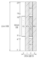
도 10은 서로 다른 뉴머럴로지의 PRB 그리드를 정렬하는 일 예를 나타낸다. 도 10을 참조하면, 15 kHz의 부반송파 간격에 대응하는 제1 뉴머럴로지의 25 RB와, 30 kHz의 부반송파 간격에 대응하는 제2 뉴머럴로지의 11 RB가 정렬되는 서로 다른 예를 나타낸다. 15 kHz의 부반송파 간격의 25 RB와 30 kHz의 부반송파 간격의 11 RB가 서로 정렬되기 위하여, 30 kHz의 부반송파 간격의 PRB 그리드가 천이될 수 있다. 이와 관련하여, 기준 부반송파 간격보다 큰 모든 부반송파 간격에 대하여 PRB 그리드의 천이가 지원되는지 여부와 서로 다른 부반송파 간격을 위하여 PRB 정렬에 대해 추가적인 제한이 필요한지 여부가 논의될 수 있다.10 illustrates an example of aligning PRB grids of different neuralologies. Referring to FIG. 10, 25 RB of the first neuralology corresponding to the 15 kHz subcarrier spacing and 11 RB of the second neuralology corresponding to the 30 kHz subcarrier spacing are arranged. A PRB grid of 30 kHz subcarrier spacing may be transitioned so that 25 RB of 15 kHz subcarrier spacing and 11 RB of 30 kHz subcarrier spacing are aligned with each other. In this regard, it may be discussed whether the transition of the PRB grid is supported for all subcarrier spacings greater than the reference subcarrier spacing and whether additional restrictions are needed for PRB alignment for different subcarrier spacings.
다른 뉴머럴로지 간의 서도 다른 PRB 그리드가 고려될 때, 기저 대역 신호 생성의 관점에서 기본 주파수가 고려될 수 있다. 기본 주파수는 주어진 뉴머럴로지 별로 반송파 대역폭의 가운데 지점 또는 주어진 뉴머럴로지 별로 각 반송파의 가장 낮은 부반송파일 수 있다. 또는, 기본 주파수는 주어진 뉴머럴로지 별로 UE의 활성 BWP의 가운데 지점 또는 주어진 뉴머럴로지 별로 UE의 활성 BWP의 가장 낮은 부반송파일 수 있다. FFT(fast Fourier transform)는 기본 주파수에 대해 0 또는 중심 주파수를 가정할 수 있다.When different PRB grids between different neuralologies are considered, the fundamental frequency may be considered in terms of baseband signal generation. The fundamental frequency may be the lowest subcarrier of each carrier for a given point in the center of the carrier bandwidth for each given neutral or given given neutrality. Alternatively, the fundamental frequency may be the lowest subcarrier of the active BWP of the UE for each given neutral or at the center of the active BWP of the UE for each given neutral. Fast Fourier transform (FFT) can assume zero or center frequency for the fundamental frequency.
NR에서 BWP 동작, 광대역 동작, 복수의 뉴머럴로지 등과 같은 다양한 시나리오로 인해, 신호의 발생/수신은 정렬된 중심 주파수(예를 들어, LTE에서처럼 반송파의 중심 주파수) 대신 각 장치의 중심 주파수에 기초할 수 있다. 그러나, 위상을 보상하기 위해, 네트워크와 UE 간의 공통 기준이 여전히 필요할 수 있다. 공통 기준은 절대 주파수 0 또는 각 주파수 영역의 시작 주파수 또는 주파수 범위 당 고정된 값의 집합(예를 들어, FR1은 0, FR2는 24000MHz) 또는 각 주파수 대역의 시작 주파수일 수 있다.Due to various scenarios such as BWP operation, wideband operation, multiple neutrals, etc. in NR, the generation / reception of the signal is based on the center frequency of each device instead of the aligned center frequency (e.g., the carrier center frequency as in LTE). can do. However, to compensate for the phase, common criteria between the network and the UE may still be needed. The common reference may be an absolute frequency of zero or a set of fixed frequencies per frequency range or the start frequency of each frequency domain (eg, FR1 is 0, FR2 is 24000 MHz) or the starting frequency of each frequency band.
즉, 신호는 송신기의 중심 주파수와 기준 주파수 사이의 오프셋을 사전 보상함으로써 공통 기준을 기반으로 생성될 수 있다. 이하의 설명에서 편의상, 송신기의 중심 주파수는 'F0'이라고 할 수 있으며, 기저 대역 신호 생성의 기준 주파수는 'd0'이라고 할 수 있다.That is, the signal may be generated based on the common reference by precompensating the offset between the center frequency and the reference frequency of the transmitter. In the following description, for convenience, the center frequency of the transmitter may be referred to as 'F0', and the reference frequency of baseband signal generation may be referred to as 'd0'.
복수의 뉴머럴로지를 고려하면, 시나리오에 따라, 각 뉴머럴로지에 대한 PRB 그리드(즉, 보호 대역)가 SS/PBCH 블록의 위치에 대해 고정되지 않을 수 있다. 예를 들어, 상술한 도 10을 참조하면, 15 kHz 부반송파 간격의 PRB 그리드가 왼쪽에서 더 큰 보호 대역을 갖는다면, 보호 대역을 대칭적으로 구성하기 위해 30 kHz 부반송파 간격의 PRB 그리드에 대해 (2)를 사용하는 것이 바람직하다. 한편, 15 kHz 부반송파 간격의 PRB 그리드가 오른쪽에 더 큰 보호 대역을 갖는다면, 30 kHz 부반송파 간격의 PRB 그리드에 대해 (3)을 사용하는 것이 바람직하다. 즉, 주파수 대역에 따라 각 뉴머럴로지에 대한 가드 밴드의 균형을 맞추기 위해, 최적의 PRB 그리드 맵핑이 다를 수 있다. 경우에 따라, 포인트 A(모든 뉴머럴로지의 부반송파 0이 정렬되는 지점)와 주어진 뉴머럴로지의 각 반송파의 가장 낮은 부반송파(또는 중심 부반송파) 간의 오프셋이 다를 수 있다.Considering a plurality of neuralologies, depending on the scenario, the PRB grid (ie guard band) for each neuralology may not be fixed relative to the position of the SS / PBCH block. For example, referring to FIG. 10 described above, if the PRB grid of 15 kHz subcarrier spacing has a larger guard band on the left side, the PRB grid of 30 kHz subcarrier spacing (2 Is preferably used. On the other hand, if the PRB grid of 15 kHz subcarrier spacing has a larger guard band on the right side, it is preferable to use (3) for the PRB grid of 30 kHz subcarrier spacing. That is, in order to balance the guard bands for the respective neuralologies according to the frequency bands, the optimal PRB grid mapping may be different. In some cases, the offset between point A (the point at which
본 발명의 일 실시예에 따르면, 다수의 뉴머럴로지에 대한 신호 생성에서, 다음의 두 가지 접근법이 고려될 수 있다.According to one embodiment of the present invention, in signal generation for multiple neuralologies, the following two approaches can be considered.
(1) 접근법 1: 각 뉴머럴로지에 대한 F0가 정렬될 수 있다. 또는, 각 뉴머럴로지에 대한 d0가 정렬될 수 있다. 예를 들어, 네트워크가 지원하거나 대역폭이 지원하는 가장 낮은 부반송파 간격 또는 가장 높은 부반송파 간격의 중심 주파수를 공통 기준으로 사용하여, 각 뉴머럴로지에 대한 F0 또는 d0가 정렬될 수 있다. (1) Approach 1: F0 for each neuralology can be aligned. Alternatively, d0 for each neuralology can be aligned. For example, using the center frequency of the lowest subcarrier spacing or the highest subcarrier spacing supported by the network or the bandwidth as a common reference, F0 or d0 for each neuralology can be aligned.
(2) 접근법 2: 각 뉴머럴로지에 대한 F0 또는 d0은 각 뉴머럴로지의 PRB 그리드를 기반으로 결정될 수 있다. 따라서 각 뉴머럴로지에 대한 F0 또는 d0은 뉴머럴로지마다 다를 수 있다. 각 뉴머럴로지에 대한 F0 또는 d0은 서로 정렬되지 않을 수 있다.(2) Approach 2: F0 or d0 for each neuralology can be determined based on the PRB grid of each neuralology. Thus, F0 or d0 for each numerology may vary from one neutral to another. F0 or d0 for each neuralology may not be aligned with each other.
도 11은 본 발명의 일 실시예에 따라 다수의 뉴머럴로지에 대한 신호를 생성하는 방법의 일 예를 나타낸다. 도 11에서, 네트워크 또는 대역폭이 지원하는 부반송파 간격이 15 kHz, 30 kHz, 60 kHz이고, 네트워크 또는 대역폭이 지원하는 가장 큰 부반송파 간격은 60 kHz라고 가정한다. SS/PBCH 블록은 15 KHz의 부반송파 간격을 사용하여 전송될 수 있다. 각 뉴머럴로지에 대하여 PRB 그리드가 생성될 수 있고, 포인트 A에서는 모든 뉴머럴로지에 대한 PRB 그리드에서 부반송파 0이 정렬된다. 도 11을 참조하면, 각 뉴머럴로지에 대한 신호 생성을 위하여, 각 뉴머럴로지에 대한 PRB 그리드의 중심 주파수(F0) 및/또는 각 뉴머럴로지에 대한 기저 대역 신호 생성의 기준 주파수(d0)가 공통 기준을 기반으로 정렬될 수 있다. 도 11을 참조하면, 네트워크 또는 대역폭이 지원하는 가장 높은 부반송파 간격인 60 kHz의 부반송파 간격의 중심 주파수가 공통 기준으로 사용될 수 있다. 즉, 60 kHz보다 작은 부반송파 간격인 30 kHz 또는 15 kHz 부반송파 간격에 대한 PBB 그리드에서, 중심 주파수는 60 kHz의 부반송파 간격의 중심 주파수를 기준으로 하여 천이/정렬될 수 있다. 정렬된 각 뉴머럴로지에 대한 중심 주파수에 따라, 기저 대역 신호 생성의 기준 주파수인 d0가 결정될 수 있다. 또는, 60 kHz보다 작은 부반송파 간격인 30 kHz 또는 15 kHz 부반송파 간격에 대한 PBB 그리드에서, 기저 대역 신호 생성의 기준 주파수는 60 kHz의 부반송파 간격의 중심 주파수를 기준으로 하여 천이/정렬될 수 있다.11 illustrates an example of a method for generating signals for a plurality of neuralologies according to an embodiment of the present invention. In FIG. 11, it is assumed that the subcarrier spacing supported by the network or bandwidth is 15 kHz, 30 kHz, 60 kHz, and the largest subcarrier spacing supported by the network or bandwidth is 60 kHz. The SS / PBCH block may be transmitted using a subcarrier spacing of 15 KHz. A PRB grid can be generated for each neuralology, and at
도 12는 본 발명의 다른 실시예에 따라 다수의 뉴머럴로지에 대한 신호를 생성하는 방법의 일 예를 나타낸다. 도 12에서, 네트워크 또는 대역폭이 지원하는 부반송파 간격이 15 kHz, 30 kHz, 60 kHz이고, 네트워크 또는 대역폭이 지원하는 가장 높은 부반송파 간격은 60 kHz라고 가정한다. SS/PBCH 블록은 15 KHz의 부반송파 간격을 사용하여 전송될 수 있다. 각 뉴머럴로지에 대하여 PRB 그리드가 생성될 수 있고, 포인트 A에서는 모든 뉴머럴로지에 대한 PRB 그리드에서 부반송파 0이 정렬된다. 도 12를 참조하면, 각 뉴머럴로지에 대한 PRB 그리드의 중심 주파수(F0) 및/또는 각 뉴머럴로지에 대한 기저 대역 신호 생성의 기준 주파수(d0)가 서로 정렬되지 않는다. 즉, 각 뉴머럴로지에 대한 F0는 각 뉴머럴로지의 PRB 그리드를 기반으로 결정될 수 있다. 도 11과는 다르게, 30 kHz 또는 15 kHz 부반송파 간격에 대한 PBB 그리드에서, 중심 주파수는 60 kHz의 부반송파 간격의 중심 주파수를 기준으로 하여 천이/정렬되지 않는다. 12 illustrates an example of a method for generating signals for a plurality of neuralologies according to another embodiment of the present invention. In FIG. 12, it is assumed that the subcarrier spacing supported by the network or bandwidth is 15 kHz, 30 kHz, 60 kHz, and the highest subcarrier spacing supported by the network or bandwidth is 60 kHz. The SS / PBCH block may be transmitted using a subcarrier spacing of 15 KHz. A PRB grid can be generated for each neuralology, and at
접근법 1은 서로 다른 뉴머럴로지 사이의 중심 주파수가 정렬된다는 이점이 있다. 즉, 정렬된 중심 주파수를 기반으로 하여 기저 대역 신호 생성이 수행될 수 있다. 접근법 1은 서로 다른 뉴머럴로지 사이의 FDM(frequency division multiplexing) 및 다른 뉴머럴로지 사이의 빠른 TDM(time division multiplexing)에 효과적으로 사용될 수 있다. 그러나 접근법 1은 서로 다른 뉴머럴로지 사이에서 공통 기준 주파수를 결정할 필요가 있으며, 또한 잠재적으로 뉴머럴로지 별로 서로 다른 중심 주파수가 보상될 필요가 있다.
현재의 NR 표준에서, UE에게 포인트 A(모든 뉴머럴로지의 부반송파 0이 정렬되는 지점), 포인트 A와 주어진 뉴머럴로지의 반송파의 가장 낮은 부반송파 사시의 오프셋 및 해당 반송파의 RB의 개수가 지시된다. 공통 기준 주파수를 결정하려면 특정 규칙이 필요할 수 있다. 예를 들어, 공통 기준 주파수는 동일한 주파수 대역에서 네트워크에 의해 지원되는 가장 높은 부반송파 간격 또는 가장 낮은 부반송파 간격에 대한 PRB 그리드의 중심 주파수일 수 있다. 또는, 공통 기준 주파수는 고정된 부반송파 간격(예를 들어, FR1의 경우 15 kHz, FR2의 경우 60 kHz)에 대한 PRB 그리드의 중심 주파수일 수 있다. 최대 또는 최소 부반송파 간격에 대한 PRB 그리드의 중심 주파수가 공통 기준 주파수로 사용되는 경우, 각 뉴머럴로지에 대하여 계산된 중심 주파수와 공통 기준 주파수 간의 차이값이 지시되거나 계산될 필요가 있을 수 있다. 각 뉴머럴로지에 대한 중심 주파수는 뉴머럴로지에 대하여 가장 낮은 부반송파 및 반송파의 RB의 개수를 기반으로 계산될 수 있다. 즉, 반송파의 PRB 그리드의 중심은 포인트 A와 반송파의 가장 낮은 부반송파 사이의 오프셋 및 반송파의 대한 RB의 개수로부터 유도되어 계산되는 중심 주파수일 수 있다.In the current NR standard, the UE is instructed on point A (the point at which
모든 반송파의 지원되는 뉴머럴로지가 지시되지 않으면, 각 뉴머럴로지에 대한 중심 주파수와 공통 기준 주파수의 차이가 시그널링 될 필요가 있을 수 있다. 어느 것이 기준으로 사용되는지에 따라, 서로 다른 시그널링이 필요할 수 있다. 예를 들어, 가장 작은 부반송파 간격에 대한 PRB 그리드의 중심 주파수가 공통 기준 주파수로 사용되는 경우, 가장 큰 부반송파 간격이 가장 작은 부반송파 간격의 4배이면, 각 뉴머럴로지에 대한 차이값은 {-6, -3, 0, 3, 6}일 수 있다. 가장 큰 부반송파 간격에 대한 PRB 그리드의 중심 주파수가 공통 기준 주파수로 사용되는 경우, 가장 큰 부반송파 간격이 가장 작은 부반송파 간격의 4배이면, 각 뉴머럴로지에 대한 차이값은 {-12, -6, 0, 6, 12}일 수 있다. 가장 큰 부반송파 간격이 가장 작은 부반송파 간격의 4배보다 큰 경우, -1.5와 같은 다른 값이 접근법 1에 필요할 수 있으므로 바람직하지 않을 수 있다. 이러한 경우 접근법 2를 사용해야 할 수 있다. 반송파의 가장 낮은 부반송파가 d0으로 사용되는 경우, 동일한 값 집합이 필요할 수 있다.If the supported neuralology of all carriers is not indicated, the difference between the center frequency and the common reference frequency for each neuralology may need to be signaled. Depending on which is used as a reference, different signaling may be required. For example, if the center frequency of the PRB grid for the smallest subcarrier spacing is used as the common reference frequency, if the largest subcarrier spacing is four times the smallest subcarrier spacing, then the difference value for each neuralology is {-6. , -3, 0, 3, 6}. If the center frequency of the PRB grid for the largest subcarrier spacing is used as the common reference frequency, if the largest subcarrier spacing is four times the smallest subcarrier spacing, then the difference value for each numerology is {-12, -6, 0, 6, 12}. If the largest subcarrier spacing is greater than four times the smallest subcarrier spacing, other values, such as -1.5, may be undesirable since
접근법 1을 사용하는 경우, 신호 생성 및 상향 변환(up-conversion)을 위하여 다음의 옵션이 고려될 수 있다.When using
(1) 옵션 1: 뉴머럴로지의 신호 생성을 위한 d0은 공통 기준 주파수를 기반으로 보상/결정될 수 있다. 동일한 상향 변환 주파수를 허용하기 위해, 각 뉴머럴로지의 신호 생성은 공통 기준 주파수, 즉 정렬된 중심 주파수(F0)를 기반으로 하여 d0를 결정할 수 있다. 이 옵션은 각 뉴머럴로지의 PRB 그리드를 기반으로 계산된 중심 대신에 지원되는 뉴머럴로지에 대한 공통 기준 주파수인 가상 중심을 기반으로 자원을 맵핑하는 것으로 이해될 수 있다. 자원 맵핑 관점에서, d0의 부반송파 인덱스는 오프셋이 적용되는지 여부에 따라 다를 수 있다. 이 옵션을 사용하기 위하여, 각 뉴머럴로지의 PRB 그리드 정보가 RMSI 수신 전에 제공되지 않으므로, SS/PBCH 블록 및/또는 RMSI의 전송은 이 오프셋을 고려하지 않거나 오프셋 값이 0이라고 가정할 수 있다. 그러나 이는 UE가 반송파 정보 및/또는 뉴머럴로지 특정 오프셋 값의 명시적 시그널링을 수신한 이후에 RMSI 전송에 대하여 혼란을 야기할 수 있다. 따라서, 초기 DL BWP에서의 모든 전송 및/또는 초기 DL BWP에서의 SS/PBCH 블록/RMSI 전송 및/또는 SS/PBCH 전송 및 RMSI 수신 이전의 RMSI 전송(예를 들어, RMSI 업데이트, 초기 접속)에 대해서는 뉴머럴로지 특정 오프셋이 적용되지 않는다고 가정할 수 있다.(1) Option 1: d0 for signal generation of neuralology may be compensated / determined based on a common reference frequency. In order to allow the same up-conversion frequency, the signal generation of each neuralology may determine
또는, RMSI에 사용된 뉴머럴로지에 대한 PRB 그리드가 기준으로 사용될 수 있다. UE 특정 BWP에서 RMSI가 또한 모니터링 되는 경우, RMSI에 사용되는 뉴머럴로지는 초기 DL BWP에서 사용되는 뉴머럴로지일 수 있다. 따라서, RMSI를 읽는 데에 모호성이 발생하지 않으며, SS/PBCH 블록은 복수의 뉴머럴로지를 고려하지 않고 전송될 수 있다. 오프셋은 RMSI에 사용된 뉴머럴로지에 대한 PRB 그리드의 계산된 중심이 공통 기준 주파수라고 가정하고 결정될 수 있다. 이 경우, 가장 큰 부반송파 간격이 네트워크 또는 대역에 의해 지원되는 가장 작은 부반송파 간격의 4배보다 크지 않으면 오프셋 값은 {-12, -9, -6, -3, 0, 3, 6, 9}일 수 있다.Alternatively, a PRB grid for the neuralology used in the RMSI may be used as a reference. If the RMSI is also monitored at the UE specific BWP, the neuralology used for the RMSI may be the neuralology used at the initial DL BWP. Thus, no ambiguity occurs in reading the RMSI, and the SS / PBCH block can be transmitted without considering a plurality of neuralologies. The offset may be determined assuming that the calculated center of the PRB grid for the neuralology used in the RMSI is a common reference frequency. In this case, the offset value is {-12, -9, -6, -3, 0, 3, 6, 9} unless the largest subcarrier spacing is greater than four times the smallest subcarrier spacing supported by the network or band. Can be.
아래에서 설명 할 다른 옵션에 대해서도 유사한 문제가 발생할 수 있으며, 유사한 방식을 사용하여 문제를 완화할 수 있다.Similar problems can arise for other options described below, and similar approaches can be used to mitigate them.
(2) 옵션 2: 뉴머럴로지의 신호 생성을 위한 d0은 서로 다른 뉴머럴로지 사이의 정렬을 위한 보상/오프셋을 고려하지 않고 자체 뉴머럴로지만을 기반으로 할 수 있다. 각 뉴머럴로지에 대해 서로 다른 상향 변환 주파수가 사용될 수 있고, 공통 기준 주파수(상이한 상향 변환 주파수, 즉 상이한 fbase + fgap u)가 각 뉴머럴로지에 대해 사용될 수 있다. 예를 들어, 계산된 중심 주파수와 공통 기준 주파수의 차이에 따라 중심 주파수가 2GHz 인 경우, 2GHz + 오프셋*부반송파 간격[kHz]이 주어진 뉴머럴로지에 대한 상향 변환에 사용될 수 있다. 옵션 1에서 설명한 것처럼, RMSI와 다른 채널 간의 다른 접근 방식을 가지고 처리하는 것이 이 옵션에서도 필요할 수 있다. 즉, 공통 기준 주파수는 RMSI에 사용된 뉴머럴로지를 기반으로 하여 결정될 수 있다. 즉, 이 옵션은 상향 변환에서의 fTX(각 뉴머럴로지에 대해 계산된 중심 주파수)가 복수의 뉴머럴로지에 걸쳐 동일하고(기준 뉴머럴로지에 따라 결정됨), 수신기 측에서 f0를 결정할 때, 각 뉴머럴로지에 대한 f0는 f0base + Δu (뉴머럴로지 특정 오프셋)으로 계산될 수 있다. 여기서 f0base는 모든 뉴머럴로지에서 공통이며, 기준 뉴머럴로지에 따라 결정될 수 있다. fTX - fRX 간의 위상 보상은 OFDM 심볼 별로 수행될 수 있다.(2) Option 2: The d0 for signal generation of the neuralology can be based on its own neural loom without considering the compensation / offset for alignment between different neuralologies. Different upconversion frequencies may be used for each neuralology, and a common reference frequency (different upconversion frequencies, ie different f base + f gap u ) may be used for each neuralology. For example, when the center frequency is 2 GHz according to the difference between the calculated center frequency and the common reference frequency, 2 GHz + offset * subcarrier spacing [kHz] may be used for up-conversion for a given neuralology. As described in
(3) 옵션 3: 신호 생성을 위한 d0은 자체 뉴머럴로지만을 기반으로 할 수 있으며, 각 뉴머럴로지에 대한 상향 변환 주파수 또한 고정될 수 있다. 각 뉴머러롤지의 계산된 중심 주파수와 공통 기준 주파수 간의 갭 및 디지털 회전자(digital rotator)가 값을 보상하는 데에 사용될 수 있다. 즉, Δu (뉴머럴로지 특정 오프셋)는 자원 맵핑 및 상향 변환과 별도로 적용될 수 있습니다. 바꾸어 말하면, 각 뉴머럴로지에 대한 위상 보상은 송신기 측에서 fTX (각 뉴머럴로지에 대해 계산된 중심 주파수) - fbase + Δu (뉴머럴로지 특정 오프셋)에서 수행될 수 있다. 수신기 측에서도 유사한 동작이 또한 수행될 수 있다.(3) Option 3: d0 for signal generation can be based on its own neural logic only, and the upconversion frequency for each neuralology can also be fixed. A digital rotator and a gap between the calculated center frequency of each neutral roll paper and the common reference frequency can be used to compensate for the value. That is, Δ u (numeric specific offset) can be applied separately from resource mapping and up-conversion. In other words, phase compensation for each numerology can be performed at the transmitter side at f TX (center frequency calculated for each neuralology) minus f base + Δ u (numericology specific offset). Similar operations may also be performed at the receiver side.
(4) 옵션 4: 신호 생성을 위한 d0은 자체 뉴머럴로지만을 기반으로 할 수 있으며, 각 뉴머럴로지에 대한 상향 변환 주파수 또한 고정될 수 있다. 각 뉴머럴로지에 대한 중심 주파수는 수신기의 관점에서 잠재적으로 상이할 수 있고(즉, 옵션 2와 유사함), 송신기는 각 뉴머럴로지의 중심 주파수와 뉴머럴로지를 위하여 사용된 실제 중심 주파수 간의 차이를 보상할 수 있다. 수신기 측에서 각 뉴머럴로지의 계산된 중심 주파수는 상향 변환/위상 보상을 위하여 사용될 수 있다. (4) Option 4: d0 for signal generation can be based on its own neutrals only, and the up-conversion frequency for each neutral can also be fixed. The center frequency for each numerology can potentially be different from the receiver's point of view (ie, similar to option 2), and the transmitter can vary between the center frequency of each neuralology and the actual center frequency used for the neuralology. The difference can be compensated. The calculated center frequency of each neuralology at the receiver side can be used for up-conversion / phase compensation.
유사한 옵션이 수신기에 대해 고려될 수 있으며, 옵션 (3)은 회전 대신 디지털 반전을 사용할 수 있다.Similar options may be considered for the receiver, and option (3) may use digital inversion instead of rotation.
위에서 설명한 옵션을 실현하기 위하여, 다음의 사항이 고려될 수 있다.In order to realize the options described above, the following may be considered.
- 기저 대역 신호 생성에서 각 뉴머럴로지에 대해 서로 다른 오프셋 값이 적용될 수 있다. 상기 오프셋 값은 상술한 바와 같이 지시된 뉴머럴로지의 반송파(자신의 것을 포함)에 대한 정보 또는 명시적 시그널링을 기반으로 각 뉴머럴로지 별로 결정될 수 있다. RMSI 수신에서의 모호성을 피하기 위해, 초기 DL BWP에 사용된 뉴머럴로지가 기준으로 사용될 수 있다.Different offset values may be applied for each neuralology in baseband signal generation. The offset value may be determined for each numerology based on information or explicit signaling about a carrier (including its own) of the indicated numerology as described above. To avoid ambiguity in RMSI reception, the neuralology used in the initial DL BWP may be used as a reference.
- 기저 대역 신호 생성에서 오프셋 값이 적용되지 않을 수 있다. 상향 변환 주파수 f0u (즉, fbase + fgap u)는 뉴머럴로지 별로 결정될 수 있다. 각 뉴머럴로지의 f0u 값은 상술한 바와 같이 지시된 뉴머럴로지의 반송파(자신의 것을 포함)에 대한 정보 또는 명시적 시그널링을 기반으로 각 뉴머럴로지 별로 결정될 수 있다. RMSI 수신에서의 모호성을 피하기 위해, 초기 DL BWP에 사용된 뉴머럴로지가 기준으로 사용될 수 있다.Offset values may not be applied in baseband signal generation. The up-conversion frequency f0 u (that is, f base + f gap u ) may be determined per neuralology. The f0 u value of each neuralology may be determined for each neuralology based on information or explicit signaling on a carrier (including its own) of the indicated neuralology as described above. To avoid ambiguity in RMSI reception, the neuralology used in the initial DL BWP may be used as a reference.
- 기저 대역 신호 생성/상향 변환에서 오프셋 값이 적용되지 않을 수 있고, 상향 변환을 위해 공통 기준 주파수가 사용될 수 있다. 그러나, UE는 상술한 바와 같이 지시된 뉴머럴로지의 반송파(자신의 것을 포함)에 대한 정보 또는 명시적 시그널링을 기반으로 결정되는 오프셋만큼 주어진 뉴머럴로지에 대해 천이가 필요할 수 있다. UE/gNB가 이러한 천이를 구현하는 방법은 UE/gNB 구현에 달려 있다. RMSI 수신에서의 모호성을 피하기 위해, 초기 DL BWP에 사용된 뉴머럴로지가 기준으로 사용될 수 있다.Offset values may not be applied in baseband signal generation / upconversion, and a common reference frequency may be used for upconversion. However, the UE may require a transition for a given neuralology by an offset determined based on information or carrier signaling of the indicated neuralology (including its own) as described above. How the UE / gNB implements this transition depends on the UE / gNB implementation. To avoid ambiguity in RMSI reception, the neuralology used in the initial DL BWP may be used as a reference.
- 기저 대역 신호 생성/상향 변환에서 오프셋 값이 적용되지 않을 수 있고, 상향 변환을 위해 공통 기준 주파수가 사용될 수 있다. 송신기는 각 뉴머럴로지의 계산된 중심 주파수와 사용된 뉴머럴로지의 중심 주파수 사이의 오프셋을 보상할 수 있고, 수신기는 각 뉴머럴로지에 대해 계산된 중심 주파수를 위상 보정을 위한 송신기 주파수 기준으로서 사용할 수 있다.Offset values may not be applied in baseband signal generation / upconversion, and a common reference frequency may be used for upconversion. The transmitter can compensate for the offset between the calculated center frequency of each neuralology and the center frequency of the used numerology, and the receiver uses the calculated center frequency for each neuralology as the transmitter frequency reference for phase correction. Can be used
gNB와 UE는 상술한 옵션 중 다른 옵션을 취할 수 있다. 예를 들어, gNB는 뉴머럴로지 특정 오프셋을 고려하여 기저 대역 신호를 생성할 수 있는 반면, UE는 신호 생성에 뉴머럴로지 특정 오프셋을 사용하지 않을 수 있다. 이러한 차이는 상술한 옵션 (2) 또는 (3)과 같이 상향 변환 또는 디지털 반전에 의해 보상될 수 있다. 즉, 상향 변환에서 뉴머럴로지 특정 f0 (즉, f0u)가 도입될 수 있고, f0는 UE 구현에 따라 다른 뉴머럴로지 사이에서 동일할 수도 있고 다를 수도 있다. UE가 뉴머럴로지 특정 f0를 계산하는 방법은 UE 구현에 달려 있다..The gNB and the UE may take another of the above-described options. For example, the gNB may generate a baseband signal in consideration of the neuralology specific offset, while the UE may not use the neuralology specific offset for signal generation. This difference can be compensated for by up-conversion or digital inversion as in option (2) or (3) above. That is, a neuralology specific f 0 (ie, f 0 u ) may be introduced in the up-conversion, and
도 13은 본 발명의 일 실시예에 따른 UE가 신호를 생성하는 방법을 나타낸다. 상술한 본 발명의 자세한 설명, 특히 접근법 1이 본 실시예에 적용될 수 있다.13 illustrates a method for generating a signal by a UE according to an embodiment of the present invention. The above detailed description of the invention, in
단계 S1300에서, UE는 반송파의 중심 주파수를 기반으로 뉴머럴로지에 대하여 신호를 생성한다. 상기 반송파의 중심 주파수는 네트워크가 지원하는 가장 큰 부반송파 간격을 기반으로 할 수 있다. 상기 반송파의 중심 주파수가 상기 네트워크가 지원하는 상기 가장 큰 부반송파 간격의 PRB 그리드의 중심 주파수에 따라 천이될 수 있다. 서로 다른 뉴머럴로지에 대한 중심 주파수가 상기 네트워크가 지원하는 상기 가장 큰 부반송파 간격의 상기 PRB 그리드의 중심 주파수에서 서로 정렬될 수 있다. 상기 반송파의 중심 주파수는 포인트 A로부터의 오프셋 및 상기 반송파의 RB의 개수를 기반으로 결정될 수 있다. 한편, UE는 상기 반송파의 중심 주파수와 상기 네트워크가 지원하는 상기 가장 큰 부반송파 간격의 상기 PRB 그리드의 중심 주파수 간의 오프셋에 대한 정보를 수신할 수 있다.In step S1300, the UE generates a signal for the neuralology based on the center frequency of the carrier. The center frequency of the carrier may be based on the largest subcarrier spacing supported by the network. The center frequency of the carrier may be shifted according to the center frequency of the PRB grid of the largest subcarrier interval supported by the network. Center frequencies for different neuralologies may be aligned with each other at the center frequency of the PRB grid of the largest subcarrier spacing that the network supports. The center frequency of the carrier may be determined based on an offset from point A and the number of RBs of the carrier. Meanwhile, the UE may receive information about an offset between the center frequency of the carrier and the center frequency of the PRB grid of the largest subcarrier interval supported by the network.
단계 S1310에서, UE는 상기 생성된 신호를 전송한다.In step S1310, the UE transmits the generated signal.
도 13에서 설명된 본 발명의 일 실시예에 따르면, 서로 다른 뉴머럴로지에 대한 신호가 정렬되어 생성될 수 있다. 즉, 네트워크가 지원하는 가장 큰 부반송파 간격에 대한 PRB 그리드에 대한 중심 주파수를 기준으로 하여, 이보다 작은 부반송파 간격에 대한 PRB 그리드의 중심 주파수 또는 기저 대역 신호 생성을 위한 기준 주파수가 천이될 수 있다. According to an embodiment of the present invention described in FIG. 13, signals for different neuralologies may be generated in alignment. That is, based on the center frequency of the PRB grid for the largest subcarrier spacing supported by the network, the center frequency of the PRB grid for the smaller subcarrier spacing or the reference frequency for baseband signal generation may be shifted.
도 14는 본 발명의 실시예가 구현되는 무선 통신 시스템을 나타낸다.14 illustrates a wireless communication system in which an embodiment of the present invention is implemented.
UE(1400)는 프로세서(processor; 1410), 메모리(memory; 1420) 및 송수신부(1430)를 포함한다. 프로세서(1410)는 본 명세서에서 설명된 기능, 과정 및/또는 방법을 구현하도록 구성될 수 있다. 무선 인터페이스 프로토콜의 계층들은 프로세서(1410)에서 구현될 수 있다. 보다 구체적으로, 프로세서(1410)는 반송파의 중심 주파수를 기반으로 뉴머럴로지에 대하여 신호를 생성하도록 구성된다. 상기 반송파의 중심 주파수는 네트워크가 지원하는 가장 큰 부반송파 간격을 기반으로 할 수 있다. 상기 반송파의 중심 주파수가 상기 네트워크가 지원하는 상기 가장 큰 부반송파 간격의 PRB 그리드의 중심 주파수에 따라 천이될 수 있다. 서로 다른 뉴머럴로지에 대한 중심 주파수가 상기 네트워크가 지원하는 상기 가장 큰 부반송파 간격의 상기 PRB 그리드의 중심 주파수에서 서로 정렬될 수 있다. 상기 반송파의 중심 주파수는 포인트 A로부터의 오프셋 및 상기 반송파의 RB의 개수를 기반으로 결정될 수 있다. 한편, 프로세서(1410)는 상기 반송파의 중심 주파수와 상기 네트워크가 지원하는 상기 가장 큰 부반송파 간격의 상기 PRB 그리드의 중심 주파수 간의 오프셋에 대한 정보를 수신하도록 송수신부(1430)를 제어할 수 있다.The
프로세서(1410)는 상기 생성된 신호를 전송하도록 송수신부(1430)를 제어할 수 있다.The
메모리(1420)는 프로세서(1410)와 연결되어, 프로세서(1410)를 구동하기 위한 다양한 정보를 저장한다. 송수신부(1430)는 프로세서(1410)와 연결되어, 네트워크 노드(1500)로 무선 신호를 전송하거나, 네트워크 노드(1500)로부터 무선 신호를 수신한다. The
네트워크 노드(1500)는 프로세서(1510), 메모리(1520) 및 송수신부(1530)를 포함한다. 프로세서(1510)는 본 명세서에서 설명된 기능, 과정 및/또는 방법을 구현하도록 구성될 수 있다. 무선 인터페이스 프로토콜의 계층들은 프로세서(1510)에서 구현될 수 있다. 메모리(1520)는 프로세서(1510)와 연결되어, 프로세서(1510)를 구동하기 위한 다양한 정보를 저장한다. 송수신부(1530)는 프로세서(1510)와 연결되어, UE(1400)로 무선 신호를 전송하거나, UE(1400)로부터 무선 신호를 수신한다. The
프로세서(1410, 1510)은 ASIC(application-specific integrated circuit), 다른 칩셋, 논리 회로 및/또는 데이터 처리 장치를 포함할 수 있다. 메모리(1420, 1520)는 ROM(read-only memory), RAM(random access memory), 플래시 메모리, 메모리 카드, 저장 매체 및/또는 다른 저장 장치를 포함할 수 있다. 송수신부(1430, 1530)는 무선 주파수 신호를 처리하기 위한 베이스밴드 회로를 포함할 수 있다. 실시예가 소프트웨어로 구현될 때, 상술한 기법은 상술한 기능을 수행하는 모듈(과정, 기능 등)로 구현될 수 있다. 모듈은 메모리(1420, 1520)에 저장되고, 프로세서(1410, 1510)에 의해 실행될 수 있다. 메모리(1420, 1520)는 프로세서(1410, 1510) 내부 또는 외부에 있을 수 있고, 잘 알려진 다양한 수단으로 프로세서(1410, 1510)와 연결될 수 있다.
도 14에서 설명된 본 발명의 일 실시예에 따르면, 서로 다른 뉴머럴로지에 대한 신호가 정렬되어 생성될 수 있다. 즉, 네트워크가 지원하는 가장 큰 부반송파 간격에 대한 PRB 그리드에 대한 중심 주파수를 기준으로 하여, 이보다 작은 부반송파 간격에 대한 PRB 그리드의 중심 주파수 또는 기저 대역 신호 생성을 위한 기준 주파수가 천이될 수 있다. According to an embodiment of the present invention described in FIG. 14, signals for different neuralologies may be generated in alignment. That is, based on the center frequency of the PRB grid for the largest subcarrier spacing supported by the network, the center frequency of the PRB grid for the smaller subcarrier spacing or the reference frequency for baseband signal generation may be shifted.
상술한 예시적인 시스템에서, 상술된 본 발명의 특징에 따라 구현될 수 있는 방법들은 순서도를 기초로 설명되었다. 편의상 방법들은 일련의 단계 또는 블록으로 설명되었으나, 청구된 본 발명의 특징은 단계들 또는 블록들의 순서에 한정되는 것은 아니며, 어떤 단계는 다른 단계와 상술한 바와 다른 순서로 또는 동시에 발생할 수 있다. 또한, 당업자라면 순서도에 나타낸 단계들이 배타적이지 않고, 다른 단계가 포함되거나 순서도의 하나 또는 그 이상의 단계가 본 발명의 범위에 영향을 미치지 않고 삭제될 수 있음을 이해할 수 있을 것이다.In the exemplary system described above, methods that may be implemented in accordance with the above-described features of the present invention have been described based on a flowchart. For convenience, the methods have been described as a series of steps or blocks, but the claimed features of the present invention are not limited to the order of steps or blocks, and certain steps may occur in the same order as other steps and in a different order than described above. In addition, those skilled in the art will appreciate that the steps shown in the flowcharts are not exclusive and that other steps may be included or one or more steps in the flowcharts may be deleted without affecting the scope of the present invention.
Claims (6)
복수의 부반송파 간격에 대한 각 자원 블록 그리드의 기준점인 포인트 A에 대한 정보를 수신하고, 상기 복수의 부반송파 간격은 제1 부반송파 간격과 제2 부반송파 간격을 포함하고, 상기 제1 부반송파 간격은 반송파에서 네트워크가 지원하는 가장 큰 부반송파 간격이고, 상기 제2 부반송파 간격은 상기 제1 부반송파 간격과 다른 부반송파 간격이고;
상기 제1 부반송파 간격에 대하여 상기 포인트 A와 상기 반송파의 가장 낮은 부반송파 간의 오프셋인 제1 오프셋에 대한 정보 및 상기 제1 부반송파 간격에 대한 상기 반송파의 자원 블록의 개수에 대한 정보를 수신하고;
상기 제2 부반송파 간격에 대하여 상기 포인트 A와 상기 반송파의 가장 낮은 부반송파 간의 오프셋인 제2 오프셋에 대한 정보 및 상기 제2 부반송파 간격에 대한 상기 반송파의 자원 블록의 개수에 대한 정보를 수신하고;
상기 제1 오프셋 및 상기 제1 부반송파 간격에 대한 상기 반송파의 자원 블록의 개수를 기반으로 상기 제1 부반송파 간격을 기반으로 하는 제1 중심 주파수를 결정하고;
상기 제2 오프셋 및 상기 제2 부반송파 간격에 대한 상기 반송파의 자원 블록의 개수를 기반으로 상기 제2 부반송파 간격을 기반으로 하는 제2 중심 주파수를 결정하고;
상기 제1 중심 주파수와 상기 제2 중심 주파수 간의 차이를 계산하고;
상기 차이를 기반으로 상기 제2 부반송파 간격에 대하여 신호를 생성하고,
상기 생성된 신호를 전송하는 것을 포함하는 방법.In a method performed by a wireless device in a wireless communication system,
Receives information about point A, which is a reference point of each resource block grid for a plurality of subcarrier spacings, wherein the plurality of subcarrier spacings includes a first subcarrier spacing and a second subcarrier spacing, wherein the first subcarrier spacing is a network on a carrier. Is the largest subcarrier spacing supported, and the second subcarrier spacing is a subcarrier spacing different from the first subcarrier spacing;
Receive information on a first offset which is an offset between the point A and the lowest subcarrier of the carrier and information on the number of resource blocks of the carrier for the first subcarrier spacing for the first subcarrier spacing;
Receive information on a second offset which is an offset between the point A and the lowest subcarrier of the carrier and information on the number of resource blocks of the carrier for the second subcarrier spacing for the second subcarrier spacing;
Determine a first center frequency based on the first subcarrier spacing based on the number of resource blocks of the carrier with respect to the first offset and the first subcarrier spacing;
Determine a second center frequency based on the second subcarrier spacing based on the number of resource blocks of the carrier with respect to the second offset and the second subcarrier spacing;
Calculate a difference between the first center frequency and the second center frequency;
Generate a signal for the second subcarrier spacing based on the difference;
Transmitting the generated signal.
상기 제2 부반송파에 대한 기저 대역 신호 생성의 기준 주파수가 상기 제1 부반송파 간격을 기반으로 하는 중심 주파수에 정렬되는 것을 특징으로 하는 방법.The method of claim 1,
And a reference frequency of baseband signal generation for the second subcarrier is aligned to a center frequency based on the first subcarrier spacing.
하나 이상의 송수신부;
하나 이상의 프로세서; 및
상기 하나 이상의 프로세서와 동작 가능하게 연결될 수 있는 하나 이상의 메모리를 포함하며,
상기 하나 이상의 메모리는 상기 하나 이상의 프로세서에 의해 수행되는 것을 기반으로,
복수의 부반송파 간격에 대한 각 자원 블록 그리드의 기준점인 포인트 A에 대한 정보를 수신하고, 상기 복수의 부반송파 간격은 제1 부반송파 간격과 제2 부반송파 간격을 포함하고, 상기 제1 부반송파 간격은 반송파에서 네트워크가 지원하는 가장 큰 부반송파 간격이고, 상기 제2 부반송파 간격은 상기 제1 부반송파 간격과 다른 부반송파 간격이고;
상기 제1 부반송파 간격에 대하여 상기 포인트 A와 상기 반송파의 가장 낮은 부반송파 간의 오프셋인 제1 오프셋에 대한 정보 및 상기 제1 부반송파 간격에 대한 상기 반송파의 자원 블록의 개수에 대한 정보를 수신하고;
상기 제2 부반송파 간격에 대하여 상기 포인트 A와 상기 반송파의 가장 낮은 부반송파 간의 오프셋인 제2 오프셋에 대한 정보 및 상기 제2 부반송파 간격에 대한 상기 반송파의 자원 블록의 개수에 대한 정보를 수신하고;
상기 제1 오프셋 및 상기 제1 부반송파 간격에 대한 상기 반송파의 자원 블록의 개수를 기반으로 상기 제1 부반송파 간격을 기반으로 하는 제1 중심 주파수를 결정하고;
상기 제2 오프셋 및 상기 제2 부반송파 간격에 대한 상기 반송파의 자원 블록의 개수를 기반으로 상기 제2 부반송파 간격을 기반으로 하는 제2 중심 주파수를 결정하고;
상기 제1 중심 주파수와 상기 제2 중심 주파수 간의 차이를 계산하고;
상기 차이를 기반으로 상기 제2 부반송파 간격에 대하여 신호를 생성하고,
상기 생성된 신호를 전송하는 것을 포함하는 동작을 수행하도록 하는 명령을 저장하는 것을 특징으로 하는 무선 기기.A wireless device configured to operate in a wireless communication system, the wireless device comprising:
One or more transceivers;
One or more processors; And
At least one memory operatively coupled to the at least one processor,
Wherein the one or more memories are performed by the one or more processors,
Receives information about point A, which is a reference point of each resource block grid for a plurality of subcarrier spacings, wherein the plurality of subcarrier spacings includes a first subcarrier spacing and a second subcarrier spacing, wherein the first subcarrier spacing is a network on a carrier. Is the largest subcarrier spacing supported, and the second subcarrier spacing is a subcarrier spacing different from the first subcarrier spacing;
Receive information on a first offset which is an offset between the point A and the lowest subcarrier of the carrier and information on the number of resource blocks of the carrier for the first subcarrier spacing for the first subcarrier spacing;
Receive information on a second offset which is an offset between the point A and the lowest subcarrier of the carrier and information on the number of resource blocks of the carrier for the second subcarrier spacing for the second subcarrier spacing;
Determine a first center frequency based on the first subcarrier spacing based on the number of resource blocks of the carrier with respect to the first offset and the first subcarrier spacing;
Determine a second center frequency based on the second subcarrier spacing based on the number of resource blocks of the carrier with respect to the second offset and the second subcarrier spacing;
Calculate a difference between the first center frequency and the second center frequency;
Generate a signal for the second subcarrier spacing based on the difference;
And store a command to perform an operation comprising transmitting the generated signal.
상기 제2 부반송파에 대한 기저 대역 신호 생성의 기준 주파수가 상기 제1 부반송파 간격을 기반으로 하는 중심 주파수에 정렬되는 것을 특징으로 하는 무선 기기.The method of claim 3, wherein
And a reference frequency of baseband signal generation for the second subcarrier is aligned to a center frequency based on the first subcarrier spacing.
복수의 부반송파 간격에 대한 각 자원 블록 그리드의 기준점인 포인트 A에 대한 정보를 수신하고, 상기 복수의 부반송파 간격은 제1 부반송파 간격과 제2 부반송파 간격을 포함하고, 상기 제1 부반송파 간격은 반송파에서 네트워크가 지원하는 가장 큰 부반송파 간격이고, 상기 제2 부반송파 간격은 상기 제1 부반송파 간격과 다른 부반송파 간격이고;
상기 제1 부반송파 간격에 대하여 상기 포인트 A와 상기 반송파의 가장 낮은 부반송파 간의 오프셋인 제1 오프셋에 대한 정보 및 상기 제1 부반송파 간격에 대한 상기 반송파의 자원 블록의 개수에 대한 정보를 수신하고;
상기 제2 부반송파 간격에 대하여 상기 포인트 A와 상기 반송파의 가장 낮은 부반송파 간의 오프셋인 제2 오프셋에 대한 정보 및 상기 제2 부반송파 간격에 대한 상기 반송파의 자원 블록의 개수에 대한 정보를 수신하고;
상기 제1 오프셋 및 상기 제1 부반송파 간격에 대한 상기 반송파의 자원 블록의 개수를 기반으로 상기 제1 부반송파 간격을 기반으로 하는 제1 중심 주파수를 결정하고;
상기 제2 오프셋 및 상기 제2 부반송파 간격에 대한 상기 반송파의 자원 블록의 개수를 기반으로 상기 제2 부반송파 간격을 기반으로 하는 제2 중심 주파수를 결정하고;
상기 제1 중심 주파수와 상기 제2 중심 주파수 간의 차이를 계산하고;
상기 차이를 기반으로 상기 제2 부반송파 간격에 대하여 신호를 생성하고,
상기 생성된 신호를 전송하도록 상기 무선 기기를 제어하도록 구성되는 것을 특징으로 하는 프로세서.A processor for a wireless device in a wireless communication system, the processor comprising:
Receives information about point A, which is a reference point of each resource block grid for a plurality of subcarrier spacings, wherein the plurality of subcarrier spacings includes a first subcarrier spacing and a second subcarrier spacing, wherein the first subcarrier spacing is a network on a carrier. Is the largest subcarrier spacing supported, and the second subcarrier spacing is a subcarrier spacing different from the first subcarrier spacing;
Receive information on a first offset which is an offset between the point A and the lowest subcarrier of the carrier and information on the number of resource blocks of the carrier for the first subcarrier spacing for the first subcarrier spacing;
Receive information on a second offset which is an offset between the point A and the lowest subcarrier of the carrier and information on the number of resource blocks of the carrier for the second subcarrier spacing for the second subcarrier spacing;
Determine a first center frequency based on the first subcarrier spacing based on the number of resource blocks of the carrier with respect to the first offset and the first subcarrier spacing;
Determine a second center frequency based on the second subcarrier spacing based on the number of resource blocks of the carrier with respect to the second offset and the second subcarrier spacing;
Calculate a difference between the first center frequency and the second center frequency;
Generate a signal for the second subcarrier spacing based on the difference;
And control the wireless device to transmit the generated signal.
상기 제2 부반송파에 대한 기저 대역 신호 생성의 기준 주파수가 상기 제1 부반송파 간격을 기반으로 하는 중심 주파수에 정렬되는 것을 특징으로 하는 프로세서.The method of claim 5, wherein
And a reference frequency of baseband signal generation for the second subcarrier is aligned to a center frequency based on the first subcarrier spacing.
Applications Claiming Priority (2)
| Application Number | Priority Date | Filing Date | Title |
|---|---|---|---|
| US201862658586P | 2018-04-16 | 2018-04-16 | |
| US62/658,586 | 2018-04-16 |
Related Parent Applications (1)
| Application Number | Title | Priority Date | Filing Date |
|---|---|---|---|
| KR1020190044373A Division KR20190120722A (en) | 2018-04-16 | 2019-04-16 | Method and apparatus for generating signal in wireless communication system |
Publications (2)
| Publication Number | Publication Date |
|---|---|
| KR20200026862A true KR20200026862A (en) | 2020-03-11 |
| KR102196731B1 KR102196731B1 (en) | 2020-12-30 |
Family
ID=68240161
Family Applications (2)
| Application Number | Title | Priority Date | Filing Date |
|---|---|---|---|
| KR1020190044373A KR20190120722A (en) | 2018-04-16 | 2019-04-16 | Method and apparatus for generating signal in wireless communication system |
| KR1020200026088A KR102196731B1 (en) | 2018-04-16 | 2020-03-02 | Method and apparatus for generating signal in wireless communication system |
Family Applications Before (1)
| Application Number | Title | Priority Date | Filing Date |
|---|---|---|---|
| KR1020190044373A KR20190120722A (en) | 2018-04-16 | 2019-04-16 | Method and apparatus for generating signal in wireless communication system |
Country Status (6)
| Country | Link |
|---|---|
| US (1) | US11336494B2 (en) |
| EP (1) | EP3582460B1 (en) |
| JP (1) | JP6943973B2 (en) |
| KR (2) | KR20190120722A (en) |
| CN (1) | CN110612711B (en) |
| WO (1) | WO2019203532A1 (en) |
Families Citing this family (2)
| Publication number | Priority date | Publication date | Assignee | Title |
|---|---|---|---|---|
| WO2021203413A1 (en) * | 2020-04-10 | 2021-10-14 | Lenovo (Beijing) Limited | Method and apparatus for uplink resource allocation |
| US20230180288A1 (en) * | 2020-07-15 | 2023-06-08 | Qualcomm Incorporated | Techniques for random access communication support using remotely-located nodes in a wireless network |
Family Cites Families (14)
| Publication number | Priority date | Publication date | Assignee | Title |
|---|---|---|---|---|
| KR101820731B1 (en) * | 2011-08-25 | 2018-01-22 | 삼성전자주식회사 | Communication method and apparatus in wirless communication system supporting multiple ofdm parameters set |
| US9893854B2 (en) * | 2013-09-20 | 2018-02-13 | Qualcomm Incorporated | Sequence mapping for LTE/LTE-A with unlicensed spectrum |
| US10038581B2 (en) * | 2015-06-01 | 2018-07-31 | Huawei Technologies Co., Ltd. | System and scheme of scalable OFDM numerology |
| KR102596103B1 (en) * | 2015-07-22 | 2023-10-31 | 삼성전자 주식회사 | Method and apparatus for operating machine Type communications in wireless communication system |
| MY196464A (en) * | 2015-11-11 | 2023-04-12 | Ericsson Telefon Ab L M | Method and Apparatus for Wireless Communication |
| US10356800B2 (en) | 2016-05-09 | 2019-07-16 | Qualcomm Incorporated | Scalable numerology with symbol boundary alignment for uniform and non-uniform symbol duration in wireless communication |
| US10524255B2 (en) | 2016-05-20 | 2019-12-31 | Lg Electronics Inc. | Method and apparatus for handling DC subcarrier in NR carrier in wireless communication system |
| US10419171B2 (en) | 2016-08-11 | 2019-09-17 | Qualcomm Incorporated | Flexible guard band for heterogeneous symbol lengths/subcarrier spacing |
| US10841060B2 (en) * | 2016-09-06 | 2020-11-17 | Lg Electronics Inc. | Method and apparatus for configuring resource block structure for NR in wireless communication system |
| EP3300324A1 (en) | 2016-09-23 | 2018-03-28 | Ntt Docomo, Inc. | Transmitting ofdm resource blocks with different subcarrier spacing |
| WO2018062875A1 (en) * | 2016-09-27 | 2018-04-05 | Samsung Electronics Co., Ltd. | Method and apparatus for transmitting and receiving signal in communication system using scalable frame structure |
| CN108633059B (en) * | 2017-03-25 | 2021-06-29 | 华为技术有限公司 | Method and equipment for resource allocation, method and equipment for determining partial bandwidth and method and equipment for indicating partial bandwidth |
| WO2018203672A1 (en) * | 2017-05-02 | 2018-11-08 | Samsung Electronics Co., Ltd. | Method and apparatus of initial access in next generation cellular networks |
| US10848361B2 (en) * | 2017-12-08 | 2020-11-24 | Qualcomm Incorporated | Carrier independent signal transmission and reception |
-
2019
- 2019-04-16 CN CN201980001708.XA patent/CN110612711B/en active Active
- 2019-04-16 WO PCT/KR2019/004570 patent/WO2019203532A1/en unknown
- 2019-04-16 JP JP2019553459A patent/JP6943973B2/en active Active
- 2019-04-16 EP EP19761721.0A patent/EP3582460B1/en active Active
- 2019-04-16 KR KR1020190044373A patent/KR20190120722A/en active Application Filing
- 2019-04-16 US US16/492,589 patent/US11336494B2/en active Active
-
2020
- 2020-03-02 KR KR1020200026088A patent/KR102196731B1/en active IP Right Grant
Non-Patent Citations (10)
| Title |
|---|
| 3GPP R1-1703197* * |
| 3GPP R1-1800018* * |
| 3GPP R1-1800284* * |
| 3GPP TS38.211 v15.1.0* * |
| 3GPP TSG-RAN WG1 Meeting #88, R1-1703197, 2017.02.06. * |
| 3GPP TSG-RAN WG1 Meeting #90, R1-1713733, 2017.08.12. * |
| 3GPP TSG-RAN WG1 Meeting #90, R1-1714573, 2017.08.17. * |
| 3GPP TSG-RAN WG1 Meeting #91, R1-1719372, 2017.11.18. * |
| 3GPP TSG-RAN WG1 Meeting #AH 1801, R1-1800018, 2018.01.13. * |
| 3GPP TSG-RAN WG1 Meeting #AH 1801, R1-1800284, 2018.01.12. * |
Also Published As
| Publication number | Publication date |
|---|---|
| KR102196731B1 (en) | 2020-12-30 |
| JP2020520134A (en) | 2020-07-02 |
| WO2019203532A1 (en) | 2019-10-24 |
| CN110612711A (en) | 2019-12-24 |
| EP3582460A4 (en) | 2020-04-08 |
| JP6943973B2 (en) | 2021-10-06 |
| US20210328732A1 (en) | 2021-10-21 |
| EP3582460A1 (en) | 2019-12-18 |
| KR20190120722A (en) | 2019-10-24 |
| CN110612711B (en) | 2022-05-17 |
| US11336494B2 (en) | 2022-05-17 |
| EP3582460B1 (en) | 2021-10-13 |
Similar Documents
| Publication | Publication Date | Title |
|---|---|---|
| KR102379039B1 (en) | Method and apparatus for performing random access procedure in wireless communication system | |
| KR102033127B1 (en) | Method and apparatus for operating according to group common dci in wireless communication system | |
| US11895609B2 (en) | Method and apparatus for shifting boundary of uplink subframe or uplink slot in wireless communication system | |
| US11303420B2 (en) | Method and device for performing initial connection in wireless communication system | |
| US20210092008A1 (en) | Method and apparatus for handling multiple numerologies in wireless communication system | |
| KR102046585B1 (en) | Method and apparatus for forming prb grid in wireless communication system | |
| US11363474B2 (en) | Method and apparatus for performing measurement in wireless communication system | |
| US11122640B2 (en) | Method and apparatus for handling soft buffer size with dual connectivity in wireless communication system | |
| US11882067B2 (en) | Method and apparatus for generating reference signal sequence in wireless communication system | |
| KR102196731B1 (en) | Method and apparatus for generating signal in wireless communication system | |
| KR20130078137A (en) | Apparatus and method for transmitting control information in wireless communication system |
Legal Events
| Date | Code | Title | Description |
|---|---|---|---|
| A107 | Divisional application of patent | ||
| A201 | Request for examination | ||
| E902 | Notification of reason for refusal | ||
| E701 | Decision to grant or registration of patent right | ||
| GRNT | Written decision to grant |