KR20200026190A - Electronic device and wireless communication method - Google Patents
Electronic device and wireless communication method Download PDFInfo
- Publication number
- KR20200026190A KR20200026190A KR1020197036441A KR20197036441A KR20200026190A KR 20200026190 A KR20200026190 A KR 20200026190A KR 1020197036441 A KR1020197036441 A KR 1020197036441A KR 20197036441 A KR20197036441 A KR 20197036441A KR 20200026190 A KR20200026190 A KR 20200026190A
- Authority
- KR
- South Korea
- Prior art keywords
- time interval
- transmission time
- transmission
- user equipment
- subframe
- Prior art date
Links
- 230000006854 communication Effects 0.000 title claims abstract description 141
- 238000004891 communication Methods 0.000 title claims abstract description 140
- 238000000034 method Methods 0.000 title claims abstract description 41
- 230000005540 biological transmission Effects 0.000 claims abstract description 246
- 238000012545 processing Methods 0.000 claims abstract description 57
- 230000011664 signaling Effects 0.000 claims description 50
- 230000008569 process Effects 0.000 claims description 16
- 230000007246 mechanism Effects 0.000 description 21
- 230000006870 function Effects 0.000 description 19
- 238000010586 diagram Methods 0.000 description 16
- 208000037918 transfusion-transmitted disease Diseases 0.000 description 14
- 230000001149 cognitive effect Effects 0.000 description 10
- 238000005259 measurement Methods 0.000 description 8
- 230000001960 triggered effect Effects 0.000 description 8
- 230000010267 cellular communication Effects 0.000 description 5
- 238000005516 engineering process Methods 0.000 description 5
- 238000013467 fragmentation Methods 0.000 description 4
- 238000006062 fragmentation reaction Methods 0.000 description 4
- 239000004065 semiconductor Substances 0.000 description 4
- 230000008859 change Effects 0.000 description 3
- 230000003287 optical effect Effects 0.000 description 3
- 238000004458 analytical method Methods 0.000 description 2
- 230000000712 assembly Effects 0.000 description 2
- 238000000429 assembly Methods 0.000 description 2
- 238000001514 detection method Methods 0.000 description 2
- 230000000694 effects Effects 0.000 description 2
- 230000003993 interaction Effects 0.000 description 2
- 239000004973 liquid crystal related substance Substances 0.000 description 2
- 238000012986 modification Methods 0.000 description 2
- 230000004048 modification Effects 0.000 description 2
- 238000013468 resource allocation Methods 0.000 description 2
- 238000004904 shortening Methods 0.000 description 2
- 230000005236 sound signal Effects 0.000 description 2
- 230000001133 acceleration Effects 0.000 description 1
- 238000004364 calculation method Methods 0.000 description 1
- 230000000295 complement effect Effects 0.000 description 1
- 238000004590 computer program Methods 0.000 description 1
- 238000013461 design Methods 0.000 description 1
- 230000010365 information processing Effects 0.000 description 1
- 230000007774 longterm Effects 0.000 description 1
- 238000007726 management method Methods 0.000 description 1
- 229910044991 metal oxide Inorganic materials 0.000 description 1
- 150000004706 metal oxides Chemical class 0.000 description 1
- 238000012544 monitoring process Methods 0.000 description 1
- 238000003672 processing method Methods 0.000 description 1
- 230000002123 temporal effect Effects 0.000 description 1
- 235000012431 wafers Nutrition 0.000 description 1
Images


Classifications
-
- H—ELECTRICITY
- H04—ELECTRIC COMMUNICATION TECHNIQUE
- H04W—WIRELESS COMMUNICATION NETWORKS
- H04W24/00—Supervisory, monitoring or testing arrangements
-
- H—ELECTRICITY
- H04—ELECTRIC COMMUNICATION TECHNIQUE
- H04W—WIRELESS COMMUNICATION NETWORKS
- H04W72/00—Local resource management
- H04W72/12—Wireless traffic scheduling
- H04W72/121—Wireless traffic scheduling for groups of terminals or users
-
- H—ELECTRICITY
- H04—ELECTRIC COMMUNICATION TECHNIQUE
- H04W—WIRELESS COMMUNICATION NETWORKS
- H04W72/00—Local resource management
- H04W72/04—Wireless resource allocation
- H04W72/044—Wireless resource allocation based on the type of the allocated resource
- H04W72/0446—Resources in time domain, e.g. slots or frames
-
- H—ELECTRICITY
- H04—ELECTRIC COMMUNICATION TECHNIQUE
- H04B—TRANSMISSION
- H04B17/00—Monitoring; Testing
- H04B17/30—Monitoring; Testing of propagation channels
- H04B17/309—Measuring or estimating channel quality parameters
- H04B17/318—Received signal strength
-
- H—ELECTRICITY
- H04—ELECTRIC COMMUNICATION TECHNIQUE
- H04L—TRANSMISSION OF DIGITAL INFORMATION, e.g. TELEGRAPHIC COMMUNICATION
- H04L1/00—Arrangements for detecting or preventing errors in the information received
- H04L1/0001—Systems modifying transmission characteristics according to link quality, e.g. power backoff
- H04L1/0023—Systems modifying transmission characteristics according to link quality, e.g. power backoff characterised by the signalling
-
- H—ELECTRICITY
- H04—ELECTRIC COMMUNICATION TECHNIQUE
- H04L—TRANSMISSION OF DIGITAL INFORMATION, e.g. TELEGRAPHIC COMMUNICATION
- H04L5/00—Arrangements affording multiple use of the transmission path
- H04L5/0001—Arrangements for dividing the transmission path
- H04L5/0003—Two-dimensional division
- H04L5/0005—Time-frequency
- H04L5/0007—Time-frequency the frequencies being orthogonal, e.g. OFDM(A), DMT
-
- H—ELECTRICITY
- H04—ELECTRIC COMMUNICATION TECHNIQUE
- H04L—TRANSMISSION OF DIGITAL INFORMATION, e.g. TELEGRAPHIC COMMUNICATION
- H04L5/00—Arrangements affording multiple use of the transmission path
- H04L5/003—Arrangements for allocating sub-channels of the transmission path
- H04L5/0037—Inter-user or inter-terminal allocation
-
- H—ELECTRICITY
- H04—ELECTRIC COMMUNICATION TECHNIQUE
- H04L—TRANSMISSION OF DIGITAL INFORMATION, e.g. TELEGRAPHIC COMMUNICATION
- H04L5/00—Arrangements affording multiple use of the transmission path
- H04L5/003—Arrangements for allocating sub-channels of the transmission path
- H04L5/0044—Arrangements for allocating sub-channels of the transmission path allocation of payload
-
- H—ELECTRICITY
- H04—ELECTRIC COMMUNICATION TECHNIQUE
- H04L—TRANSMISSION OF DIGITAL INFORMATION, e.g. TELEGRAPHIC COMMUNICATION
- H04L5/00—Arrangements affording multiple use of the transmission path
- H04L5/003—Arrangements for allocating sub-channels of the transmission path
- H04L5/0053—Allocation of signaling, i.e. of overhead other than pilot signals
-
- H—ELECTRICITY
- H04—ELECTRIC COMMUNICATION TECHNIQUE
- H04L—TRANSMISSION OF DIGITAL INFORMATION, e.g. TELEGRAPHIC COMMUNICATION
- H04L5/00—Arrangements affording multiple use of the transmission path
- H04L5/003—Arrangements for allocating sub-channels of the transmission path
- H04L5/0058—Allocation criteria
- H04L5/0064—Rate requirement of the data, e.g. scalable bandwidth, data priority
-
- H—ELECTRICITY
- H04—ELECTRIC COMMUNICATION TECHNIQUE
- H04L—TRANSMISSION OF DIGITAL INFORMATION, e.g. TELEGRAPHIC COMMUNICATION
- H04L5/00—Arrangements affording multiple use of the transmission path
- H04L5/0091—Signaling for the administration of the divided path
- H04L5/0092—Indication of how the channel is divided
-
- H—ELECTRICITY
- H04—ELECTRIC COMMUNICATION TECHNIQUE
- H04L—TRANSMISSION OF DIGITAL INFORMATION, e.g. TELEGRAPHIC COMMUNICATION
- H04L67/00—Network arrangements or protocols for supporting network services or applications
- H04L67/01—Protocols
- H04L67/12—Protocols specially adapted for proprietary or special-purpose networking environments, e.g. medical networks, sensor networks, networks in vehicles or remote metering networks
-
- H—ELECTRICITY
- H04—ELECTRIC COMMUNICATION TECHNIQUE
- H04W—WIRELESS COMMUNICATION NETWORKS
- H04W4/00—Services specially adapted for wireless communication networks; Facilities therefor
- H04W4/30—Services specially adapted for particular environments, situations or purposes
- H04W4/40—Services specially adapted for particular environments, situations or purposes for vehicles, e.g. vehicle-to-pedestrians [V2P]
-
- H—ELECTRICITY
- H04—ELECTRIC COMMUNICATION TECHNIQUE
- H04W—WIRELESS COMMUNICATION NETWORKS
- H04W4/00—Services specially adapted for wireless communication networks; Facilities therefor
- H04W4/70—Services for machine-to-machine communication [M2M] or machine type communication [MTC]
-
- H—ELECTRICITY
- H04—ELECTRIC COMMUNICATION TECHNIQUE
- H04W—WIRELESS COMMUNICATION NETWORKS
- H04W4/00—Services specially adapted for wireless communication networks; Facilities therefor
- H04W4/80—Services using short range communication, e.g. near-field communication [NFC], radio-frequency identification [RFID] or low energy communication
-
- H04W72/0493—
-
- H—ELECTRICITY
- H04—ELECTRIC COMMUNICATION TECHNIQUE
- H04W—WIRELESS COMMUNICATION NETWORKS
- H04W72/00—Local resource management
- H04W72/12—Wireless traffic scheduling
- H04W72/1263—Mapping of traffic onto schedule, e.g. scheduled allocation or multiplexing of flows
-
- H—ELECTRICITY
- H04—ELECTRIC COMMUNICATION TECHNIQUE
- H04W—WIRELESS COMMUNICATION NETWORKS
- H04W72/00—Local resource management
- H04W72/12—Wireless traffic scheduling
- H04W72/1263—Mapping of traffic onto schedule, e.g. scheduled allocation or multiplexing of flows
- H04W72/1268—Mapping of traffic onto schedule, e.g. scheduled allocation or multiplexing of flows of uplink data flows
-
- H04W72/1278—
-
- H—ELECTRICITY
- H04—ELECTRIC COMMUNICATION TECHNIQUE
- H04W—WIRELESS COMMUNICATION NETWORKS
- H04W72/00—Local resource management
- H04W72/20—Control channels or signalling for resource management
-
- H—ELECTRICITY
- H04—ELECTRIC COMMUNICATION TECHNIQUE
- H04W—WIRELESS COMMUNICATION NETWORKS
- H04W72/00—Local resource management
- H04W72/50—Allocation or scheduling criteria for wireless resources
- H04W72/53—Allocation or scheduling criteria for wireless resources based on regulatory allocation policies
-
- H—ELECTRICITY
- H04—ELECTRIC COMMUNICATION TECHNIQUE
- H04W—WIRELESS COMMUNICATION NETWORKS
- H04W4/00—Services specially adapted for wireless communication networks; Facilities therefor
- H04W4/30—Services specially adapted for particular environments, situations or purposes
- H04W4/40—Services specially adapted for particular environments, situations or purposes for vehicles, e.g. vehicle-to-pedestrians [V2P]
- H04W4/44—Services specially adapted for particular environments, situations or purposes for vehicles, e.g. vehicle-to-pedestrians [V2P] for communication between vehicles and infrastructures, e.g. vehicle-to-cloud [V2C] or vehicle-to-home [V2H]
-
- H—ELECTRICITY
- H04—ELECTRIC COMMUNICATION TECHNIQUE
- H04W—WIRELESS COMMUNICATION NETWORKS
- H04W4/00—Services specially adapted for wireless communication networks; Facilities therefor
- H04W4/30—Services specially adapted for particular environments, situations or purposes
- H04W4/40—Services specially adapted for particular environments, situations or purposes for vehicles, e.g. vehicle-to-pedestrians [V2P]
- H04W4/46—Services specially adapted for particular environments, situations or purposes for vehicles, e.g. vehicle-to-pedestrians [V2P] for vehicle-to-vehicle communication [V2V]
-
- H—ELECTRICITY
- H04—ELECTRIC COMMUNICATION TECHNIQUE
- H04W—WIRELESS COMMUNICATION NETWORKS
- H04W72/00—Local resource management
- H04W72/50—Allocation or scheduling criteria for wireless resources
- H04W72/51—Allocation or scheduling criteria for wireless resources based on terminal or device properties
-
- H—ELECTRICITY
- H04—ELECTRIC COMMUNICATION TECHNIQUE
- H04W—WIRELESS COMMUNICATION NETWORKS
- H04W72/00—Local resource management
- H04W72/50—Allocation or scheduling criteria for wireless resources
- H04W72/56—Allocation or scheduling criteria for wireless resources based on priority criteria
- H04W72/566—Allocation or scheduling criteria for wireless resources based on priority criteria of the information or information source or recipient
- H04W72/569—Allocation or scheduling criteria for wireless resources based on priority criteria of the information or information source or recipient of the traffic information
-
- H—ELECTRICITY
- H04—ELECTRIC COMMUNICATION TECHNIQUE
- H04W—WIRELESS COMMUNICATION NETWORKS
- H04W88/00—Devices specially adapted for wireless communication networks, e.g. terminals, base stations or access point devices
- H04W88/02—Terminal devices
-
- H—ELECTRICITY
- H04—ELECTRIC COMMUNICATION TECHNIQUE
- H04W—WIRELESS COMMUNICATION NETWORKS
- H04W92/00—Interfaces specially adapted for wireless communication networks
- H04W92/16—Interfaces between hierarchically similar devices
- H04W92/18—Interfaces between hierarchically similar devices between terminal devices
Abstract
본 개시내용은 전자 디바이스 및 무선 통신 방법에 관한 것이다. 일 실시예에 따른 무선 통신을 위한 전자 디바이스는 처리 회로를 포함하고, 여기서 처리 회로는 사용자 장비가 제1 송신 시간 간격보다 작은 짧은 송신 시간 간격으로 단거리 서비스 통신을 수행할 때, 각각이 짧은 송신 시간 간격을 갖는 적어도 2개의 상호 독립적인 송신 블록이 동일한 서브프레임에서 송신되도록 제어를 구현하고, 서브프레임의 길이는 제1 송신 시간 간격과 동일하다.The present disclosure relates to an electronic device and a method of wireless communication. An electronic device for wireless communication, in accordance with one embodiment, includes processing circuitry, where the processing circuitry each performs a short transmission time when the user equipment performs short range service communication at a short transmission time interval that is less than the first transmission time interval. Implement control such that at least two mutually independent transmission blocks having an interval are transmitted in the same subframe, and the length of the subframe is equal to the first transmission time interval.
Description
본 개시는 일반적으로 무선 통신 분야에 관한 것으로, 특히, 무선 통신을 위한 전자 디바이스, 사용자 장비 측을 위한 전자 디바이스, 및 무선 통신 방법에 관한 것이다.TECHNICAL FIELD The present disclosure generally relates to the field of wireless communications, and more particularly, to an electronic device for wireless communication, an electronic device for a user equipment side, and a method of wireless communication.
3GPP(Third Generation Partnership Project) R14에서의 PC5에 기초한 사이드링크 서브프레임은 AGC(Automatic Gain Control) 설정 및 GAP(Guard Gap) 심볼들, DMRS(Demodulation Reference Signal) 심볼들뿐만 아니라 데이터 심볼들을 포함하는 14개의 OFDM(Orthogonal Frequency Division Multiplexing) 심볼들로 구성된다. 연구들의 추가적인 진보로, V2X(Vehicle-to-X) 서비스들에 대한 낮은 레이턴시 및 높은 신뢰성을 위한 요건들을 고려하면, 예를 들어, 짧은 송신 시간 간격(short Transmission Time Interval, sTTI)의 사용을 지원하는 PC5 동작들이 제안된다. sTTI는 하나의 서브프레임의 길이보다 작고, 필요에 따라 유연하게 설정될 수 있다. 사이드링크 V2X에 대해, 차량의 고속 이동가능성이 차량의 타이밍에서의 차이가 발생할 가능성을 야기하고, 차량의 즉각적인 정보를 취득하는 것을 어렵게 만들기 때문에, sTTI의 구조가 더 적합하다.Sidelink subframes based on PC5 in 3GPP (Third Generation Partnership Project) R14 include Automatic Gain Control (AGC) setup and Guard Gap (GAP) symbols, Demodulation Reference Signal (DMRS) symbols, as well as data symbols. Orthogonal Frequency Division Multiplexing (OFDM) symbols. With further advances in studies, considering the requirements for low latency and high reliability for vehicle-to-X (V2X) services, for example, the use of short Transmission Time Interval (sTTI) is supported. PC5 operations are proposed. The sTTI is smaller than the length of one subframe and can be flexibly set as necessary. For sidelink V2X, the structure of the sTTI is more suitable because the high-speed mobility of the vehicle causes the possibility of differences in the timing of the vehicle, and makes it difficult to obtain immediate information of the vehicle.
sTTI의 채택은 V2X 서비스들에 대한 낮은 레이턴시 등과 같은 요건들을 충족시킬 수 있다. 그러나, 통신 프로세스에서, 전통적인 서브프레임 길이 TTI를 이용하는 차량은 통신 자원들의 선택/사용 시에 sTTI를 사용하는 차량과 대립할 것이다.Adoption of sTTI can meet requirements such as low latency for V2X services. However, in the communication process, a vehicle using the traditional subframe length TTI will confront the vehicle using the sTTI in the selection / use of communication resources.
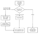
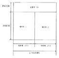
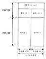
R14 사용자 장비 및 R15 사용자 장비들이 도 8에 도시된 바와 같이 공존하는 예시적인 시나리오에서, sTTI의 도입으로 인해, 다음과 같은 문제들이 발생할 수 있다: PC5에 기초한 근접-기반 서비스 통신이 7개 심볼의 길이를 갖는 sTTI를 채택하는 경우, 도 9에 도시된 바와 같이, 단 하나의 시간 슬롯이 특정 서브프레임에서의 송신에 이용되는 반면, R14 사용자 장비가 인지를 수행하는 프로세스에서, R14 사용자 장비가 서브프레임이 도 10에 도시된 바와 같은 점유 상황을 가지는 것으로 잘못 생각할 것이고, 따라서 서브프레임에 대한 부정확한 S-RSSI 결과를 획득하여, 인지 측정의 부정확성을 초래할 가능성이 있다.In an example scenario where R14 user equipment and R15 user equipments coexist as shown in FIG. 8, the following problems may arise due to the introduction of sTTI: Proximity-based service communication based on PC5 may result in seven symbols. In the case of adopting an sTTI having a length, as shown in FIG. 9, only one time slot is used for transmission in a specific subframe, while in a process in which the R14 user equipment performs acknowledgment, It will be mistaken that a frame has an occupancy situation as shown in FIG. 10, and thus there is a possibility of obtaining an incorrect S-RSSI result for a subframe, resulting in inaccuracy of cognitive measurement.
본 발명의 실시예들의 간략한 요약은 본 발명의 일부 양태들의 기본적인 이해를 제공하기 위해 아래에 주어진다. 요약은 본 발명의 철저한 요약이 아니라는 것을 이해해야 한다. 이것은 본 발명의 핵심 또는 중요한 부분을 정의하고자 의도하지 않으며, 본 발명의 범위를 제한하고자 의도하는 것도 아니다. 요약의 목적은 단지 일부 개념들을 간략하게 제시하는 것이며, 이는 뒤따라오는 상세한 설명의 전제부로서 역할을 한다.A brief summary of embodiments of the invention is given below to provide a basic understanding of some aspects of the invention. It should be understood that the summary is not an exhaustive summary of the invention. It is not intended to define key or critical parts of the invention nor is it intended to limit the scope of the invention. The purpose of the summary is to present some concepts briefly, which serve as a premise to the detailed description that follows.
실시예에 따르면, 무선 통신을 위한 전자 디바이스는: 사용자 장비가 제1 송신 시간 간격보다 작은 짧은 송신 시간 간격으로 근접-기반 서비스 통신을 수행하는 경우에, 동일한 서브프레임에서, 서로 독립적이고 각각이 짧은 송신 시간 간격을 갖는 적어도 2개의 송신 블록을 송신하기 위한 제어를 수행하도록 구성되는 처리 회로를 포함하고, 여기서 서브프레임의 길이는 제1 송신 시간 간격과 동일하다.According to an embodiment, an electronic device for wireless communication is: in the same subframe, independent of each other and each short, in the case where the user equipment performs proximity-based service communication with a short transmission time interval less than the first transmission time interval; Processing circuitry configured to perform control for transmitting at least two transmission blocks having a transmission time interval, wherein the length of the subframe is equal to the first transmission time interval.
또 다른 실시예에 따르면, 무선 통신을 위한 전자 디바이스는: 사용자 장비가 제1 송신 시간 간격보다 작은 짧은 송신 시간 간격으로 근접-기반 서비스 통신을 수행하는 경우에, 제1 송신 시간 간격과 동일한 길이를 갖는 하나의 스케줄링 할당 시그널링을 적어도 포함하는 스케줄링 할당 시그널링을 결정하고; 및 짧은 송신 시간 간격을 각각 갖는 적어도 2개의 송신 블록을 동일한 서브프레임에서 송신하기 위한 제어를 수행하도록 - 서브프레임의 길이는 제1 송신 시간 간격과 동일함 - 구성된 처리 회로를 포함한다.According to yet another embodiment, an electronic device for wireless communication comprises: when a user equipment performs proximity-based service communication at a short transmission time interval less than the first transmission time interval, the same length as the first transmission time interval. Determine scheduling assignment signaling comprising at least one scheduling assignment signaling having; And processing circuitry configured to perform control for transmitting at least two transmission blocks each having a short transmission time interval in the same subframe, wherein the length of the subframe is equal to the first transmission time interval.
또 다른 실시예에 따르면, 무선 통신 방법은: 사용자 장비가 제1 송신 시간 간격보다 작은 짧은 송신 시간 간격으로 근접-기반 서비스 통신을 수행하는 경우, 동일한 서브프레임에서, 서로 독립적이고 짧은 송신 시간 간격을 각각 갖는 적어도 2개의 송신 블록을 송신하는 단계를 포함하고, 여기서 서브프레임의 길이는 제1 송신 시간 간격과 동일하다.According to yet another embodiment, a method of wireless communication comprises: in a case where user equipment performs proximity-based service communication with a short transmission time interval smaller than a first transmission time interval, in the same subframe, independent and short transmission time intervals from each other. Transmitting at least two transmission blocks each having, wherein the length of the subframe is equal to the first transmission time interval.
또 다른 실시예에 따르면, 사용자 장비 측을 위한 전자 디바이스는 제어 노드로부터 표시 정보를 수신하기 위한 제어를 수행하고; 및 사용자 장비가 제1 송신 시간 간격보다 작은 짧은 송신 시간 간격으로 근접-기반 서비스 통신을 수행하는 경우, 사용자 장비의 송신 블록이 짧은 송신 시간 간격을 갖는 또 다른 송신 블록과 동일한 서브프레임에서 송신되도록 표시 정보에 기초하여 제어를 수행하도록 - 서브프레임의 길이는 제1 송신 시간 간격과 동일함 - 구성된 처리 회로를 포함한다.According to yet another embodiment, an electronic device for a user equipment side performs control for receiving indication information from a control node; And when the user equipment performs proximity-based service communication at a short transmission time interval smaller than the first transmission time interval, the transmission block of the user equipment is to be transmitted in the same subframe as another transmission block having a short transmission time interval. And processing circuitry configured to perform control based on the information, wherein the length of the subframe is equal to the first transmission time interval.
또 다른 실시예에 따르면, 사용자 장비 측을 위한 전자 디바이스는: 사용자 장비가 제1 송신 시간 간격으로 근접-기반 서비스 통신을 수행하는 경우에, 서로 독립적이고 및 제1 송신 시간 간격보다 작은 짧은 송신 시간 간격을 갖는, 동일한 서브프레임에서 송신되는, 적어도 2개의 송신 블록과 연관된 스케줄링 할당 시그널링을 수신하기 위한 제어를 수행하도록 구성된 처리 회로를 포함하고, 여기서 서브프레임의 길이는 제1 송신 시간 간격과 동일하다.According to another embodiment, an electronic device for the user equipment side comprises: a short transmission time that is independent of each other and smaller than the first transmission time interval when the user equipment performs proximity-based service communication in a first transmission time interval; Processing circuitry configured to perform control to receive scheduling assignment signaling associated with at least two transmission blocks, transmitted in the same subframe, having an interval, wherein the length of the subframe is equal to the first transmission time interval. .
본 발명의 실시예들을 통해, 동일한 서브프레임에서 조합하여 sTTI를 갖는 송신 블록들을 송신함으로써, sTTI 송신이 발생하는 서브프레임의 채움 정도를 올리는 것이 가능하며, 이에 의해 시간 자원들의 단편화에 관한 문제점 및/또는 인지 측정에서의 부정확성에 관한 문제점의 해결에 유리하다.Through embodiments of the present invention, by transmitting transmission blocks having sTTIs in combination in the same subframe, it is possible to increase the level of filling of a subframe in which sTTI transmissions occur, thereby causing problems with fragmentation of time resources and / or Or solving the problem of inaccuracy in cognitive measurement.
본 발명은 첨부 도면들과 함께 아래에 주어지는 설명을 참조하여 더 잘 이해될 수 있으며, 도면들 전체에 걸쳐 동일하거나 유사한 참조 부호들은 동일하거나 유사한 컴포넌트들을 나타내기 위해 사용된다. 첨부 도면들은 아래의 상세한 설명과 함께 본 명세서에 포함되고 본 명세서의 일부를 형성하여, 본 발명의 바람직한 실시예들을 심화 설명하고 예들에 의해 본 발명의 원리 및 장점을 설명한다. 첨부된 도면들은 다음과 같다.
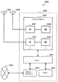
도 1은 본 발명의 실시예에 따른 무선 통신을 위한 전자 디바이스의 구성 예를 도시하는 블록도이다.
도 2는 또 다른 실시예에 따른 무선 통신을 위한 전자 디바이스의 구성 예를 도시하는 블록도이다.
도 3은 또 다른 실시예에 따른 무선 통신을 위한 전자 디바이스의 구성 예를 도시하는 블록도이다.
도 4는 본 발명의 실시예에 따른 무선 통신을 위한 전자 디바이스의 구성 예를 도시하는 블록도이다.
도 5는 본 발명의 실시예에 따른 무선 통신 방법의 프로세스 예를 도시하는 흐름도이다.
도 6은 본 발명의 실시예에 따른 사용자 장비 측을 위한 전자 디바이스의 구성 예를 도시하는 블록도이다.
도 7은 본 발명의 또 다른 실시예에 따른 사용자 장비 측을 위한 전자 디바이스의 구성 예를 도시하는 블록도이다.
도 8은 본 발명의 실시예의 응용 시나리오 예로서 상이한 송신 시간 간격들을 이용하는 사용자 장비들이 공존하는 상황을 도시하는 개략도이다.
도 9는 짧은 송신 시간 간격을 이용하는 사용자 장비의 송신 서브프레임의 실제 점유 상황의 예를 도시한다.
도 10은 긴 송신 시간 간격을 이용하는 사용자 장비의 관점에서, 도 9에 도시된 바와 같은 서브프레임의 점유 상황을 도시한다.
도 11은 예시적인 실시예에 따른 기지국과 사용자 장비 사이에 수행되는 예시적인 프로세스를 설명하기 위한 전체적인 흐름도이다.
도 12는 페어링 상황 하에서의 서브프레임 구조의 예를 도시한다.
도 13은 예시적인 실시예에 따른 페어링 프로세스를 설명하기 위한 흐름도이다.
도 14 내지 도 16은 스케줄링 할당 시그널링을 설명하기 위한 개략도들이다.
도 17은 본 개시내용의 방법들 및 장치들을 실현하는 컴퓨터의 예시적인 구조를 도시하는 블록도이다.
도 18은 본 개시내용의 기술이 적용될 수 있는 지능형 전화의 개략적 구성의 예를 도시하는 블록도이다.
도 19는 본 개시내용의 기술이 적용될 수 있는 eNB(Evolved Base Station)의 개략적 구성의 예를 도시하는 블록도이다.
도 20은 본 개시내용의 기술이 적용될 수 있는 자동차 내비게이션 장비의 개략적 구성의 예를 도시하는 블록도이다.BRIEF DESCRIPTION OF THE DRAWINGS The present invention may be better understood with reference to the description given below in conjunction with the accompanying drawings, wherein like reference numerals are used to refer to like or similar components throughout the drawings. The accompanying drawings, which are incorporated in and form part of this specification, together with the following description, further illustrate preferred embodiments of the invention and, by way of example, explain the principles and advantages of the invention. The accompanying drawings are as follows.
1 is a block diagram illustrating a configuration example of an electronic device for wireless communication according to an embodiment of the present invention.
2 is a block diagram illustrating an example of a configuration of an electronic device for wireless communication according to another embodiment.
3 is a block diagram illustrating a configuration example of an electronic device for wireless communication according to another embodiment.
4 is a block diagram illustrating an example of a configuration of an electronic device for wireless communication according to an embodiment of the present invention.
5 is a flowchart illustrating an example process of a wireless communication method according to an embodiment of the present invention.
6 is a block diagram showing an example of the configuration of an electronic device for the user equipment side according to an embodiment of the present invention.
7 is a block diagram showing an example of the configuration of an electronic device for the user equipment side according to another embodiment of the present invention.
8 is a schematic diagram illustrating a situation where user equipments using different transmission time intervals coexist as an application scenario example of an embodiment of the present invention.
9 shows an example of an actual occupancy situation of a transmission subframe of a user equipment using a short transmission time interval.
FIG. 10 illustrates the occupancy situation of a subframe as shown in FIG. 9 in terms of user equipment using a long transmission time interval.
11 is an overall flow diagram for describing an example process performed between a base station and user equipment according to an example embodiment.
12 shows an example of a subframe structure under a pairing situation.
13 is a flowchart for describing a pairing process according to an exemplary embodiment.
14 through 16 are schematic diagrams for explaining scheduling allocation signaling.
17 is a block diagram illustrating an example structure of a computer that implements the methods and apparatuses of the present disclosure.
18 is a block diagram illustrating an example of a schematic configuration of an intelligent telephone to which the technology of the present disclosure may be applied.
19 is a block diagram illustrating an example of a schematic configuration of an evolved base station (eNB) to which the techniques of this disclosure may be applied.
20 is a block diagram illustrating an example of a schematic configuration of automobile navigation equipment to which the technology of the present disclosure may be applied.
이하, 첨부 도면을 참조해서 본 발명의 실시예들이 설명될 것이다. 본 발명의 하나의 도면 또는 일 실시예에서 설명되는 요소들 및 특징들은 하나 이상의 다른 도면 또는 실시예에서 설명되는 요소들 및 특징들과 조합될 수 있다. 명료성을 위해, 본 발명과 크게 관련없는, 통상의 기술자들에게 공지된 컴포넌트 및 처리의 표현 및 설명은 첨부 도면들 및 설명에서 생략된다는 점에 유의해야 한다.Hereinafter, embodiments of the present invention will be described with reference to the accompanying drawings. Elements and features described in one drawing or embodiment of the present invention may be combined with elements and features described in one or more other drawings or embodiments. For the sake of clarity, it should be noted that the representation and description of components and processes known to those of ordinary skill in the art that are not significantly related to the present invention are omitted in the accompanying drawings and the description.
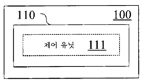
도 1에 도시된 바와 같이, 본 발명의 실시예에 따른 무선 통신을 위한 전자 디바이스(100)는 처리 회로(110)를 포함한다. 처리 회로(110)는, 예를 들어, 특정 칩, 칩셋 또는 중앙 처리 유닛(CPU) 등으로서 실현될 수 있다.As shown in FIG. 1, an
처리 회로(110)는 제어 유닛(111)을 포함한다. 제어 유닛(111) 및 다른 유닛들은 도면에서 기능 블록들의 형태로 도시되지만, 제어 유닛(111) 및 다른 유닛들의 기능들은 또한 처리 회로(110)에 의해 전체로서 실현될 수 있는데, 처리 회로(110) 내의 개별의 실제 컴포넌트들에 의해 반드시 실현될 필요는 없다는 것을 이해해야 한다는 점에 유의해야 한다. 또한, 처리 회로(110)가 도면에서 하나의 프레임에 의해 도시되지만, 전자 디바이스(100)는 복수의 처리 회로를 포함할 수 있고, 복수의 처리 회로의 협력 동작들을 통해 대응하는 기능들을 구현하기 위해서 제어 유닛(111) 및 다른 유닛들의 기능들을 복수의 처리 회로에 분배할 수 있다.The
제어 유닛(111)은: 사용자 장비가 제1 송신 시간 간격보다 작은 짧은 송신 시간 간격으로 근접-기반 서비스 통신을 수행하는 경우에, 동일한 서브프레임에서, 서로 독립적이고 짧은 송신 시간 간격을 각각 갖는 적어도 2개의 송신 블록을 송신하기 위한 제어를 수행하도록 구성되며, 여기서 서브프레임의 길이는 제1 송신 시간 간격과 동일하다.The control unit 111 includes: at least two, each having independent and short transmission time intervals from each other, in the same subframe, when the user equipment performs proximity-based service communication at a short transmission time interval smaller than the first transmission time interval. Control to transmit two transmission blocks, wherein the length of the subframe is equal to the first transmission time interval.
본 명세서에서 언급되는 "서로 독립적인"이라는 용어는 조합을 수행하지 않고서 제각기 상이한 서브프레임들에서 송신될 송신 블록들을 지칭하는데, 이것은 상이한 사용자 장비들의 송신 블록들을 포함하거나 또는 제각기 상이한 서브프레임들에서 송신될 수 있는 동일한 사용자 장비의 송신 블록들을 포함할 수 있다. 요약하면, 제어 유닛(111)에 의한 상기 언급된 처리를 수행하지 않고서, 서로 독립적인 송신 블록들은 제각기 상이한 서브프레임들에서 송신될 것인 반면, 제어 유닛(111)에 의한 처리를 통해, 서로 독립적인 송신 블록들은 동일한 서브프레임에서 조합되어 송신되도록 되어, 서브프레임의 채움 정도를 올리는 것을 가능하게 하고, 그에 의해 추가로 시간 자원들의 단편화에 관한 문제점 및 긴 송신 시간 간격을 사용하는 사용자 장비에 의한 짧은 송신 시간 간격을 사용하는 사용자 장비에 대한 인지 측정들에서의 부정확성에 관한 문제점의 해결에 유리하다.As used herein, the term "independently of each other" refers to transmission blocks to be transmitted in different subframes without performing a combination, which includes transmission blocks of different user equipments or transmits in different subframes, respectively. And may include transmission blocks of the same user equipment. In summary, without performing the above-mentioned processing by the control unit 111, transmission blocks that are independent of each other will be transmitted in different subframes, whereas, through the processing by the control unit 111, they are independent of each other. Inner transmission blocks are to be transmitted in combination in the same subframe, which makes it possible to increase the filling level of the subframe, thereby further shortening the problem of fragmentation of time resources and shortening by user equipment using a long transmission time interval. It is advantageous to address the problem of inaccuracy in cognitive measurements for user equipment using a transmission time interval.
실시예에 따르면, 서로 독립적인 적어도 2개의 송신 블록이 송신되는 서브프레임의 구조는 제1 송신 시간 간격으로 수행되는 근접-기반 서비스 통신의 서브프레임의 것과 동일할 수 있다.According to an embodiment, the structure of the subframe in which at least two transmission blocks independent of each other are transmitted may be the same as that of the subframe of proximity-based service communication performed at the first transmission time interval.
예를 들어, 제1 송신 시간 간격(이하, TTI라고 지칭될 수 있음)은 14개의 직교 주파수 분할 다중화 심볼을 포함할 수 있고, 짧은 송신 시간 간격(이하, sTTI라고 지칭될 수 있음)은 최대 7개까지의 직교 주파수 분할 다중화 심볼을 포함할 수 있다.For example, the first transmission time interval (hereinafter referred to as TTI) may include 14 orthogonal frequency division multiplexing symbols, and the short transmission time interval (hereinafter referred to as sTTI) may be up to 7 Up to orthogonal frequency division multiplexing symbols may be included.
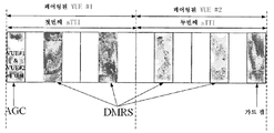
보다 구체적으로, 도 12에 도시된 바와 같이, 서브프레임에서, 제1 심볼은 AGC 설정, 제3, 제6, 제9 및 제12 심볼들은 DMRS 심볼들이고, 제14 심볼은 가드 갭 GAP의 역할을 한다. 도 12에 도시된 예에서, 서브프레임은 차량 사용자 장비들(VUE들)과 같은 2개의 사용자 장비의 송신 블록들(제각기 첫번째 sTTI 및 두번째 sTTI에 대응함)을 포함한다. 따라서, AGC는 2개의 사용자 장비(VUE1 및 VUE2)에 대한 것이다.More specifically, as shown in FIG. 12, in the subframe, the first symbol is an AGC configuration, the third, sixth, ninth, and twelfth symbols are DMRS symbols, and the fourteenth symbol serves as a guard gap GAP. do. In the example shown in FIG. 12, the subframe includes transmission blocks of two user equipment (each corresponding to the first sTTI and the second sTTI), such as vehicle user equipments (VUEs). Thus, the AGC is for two user equipments VUE1 and VUE2.
그러나, 본 발명은 상기의 예에 한정되지는 않는다. TTI는 임의의 수의 OFDM 심볼을 포함할 수 있고, sTTI는 TTI의 수보다 적은 임의의 수의 OFDM 심볼을 포함할 수 있다. 또한, 하나의 TTI에 대해, 다양한 sTTI가 존재할 수 있고, 이들 sTTI의 길이들의 합이 TTI의 길이를 초과하지 않는 한, TTI의 것과 동일한 길이를 갖는 하나의 서브프레임에서 조합되어 동일한 길이들 또는 상이한 길이들을 갖는 sTTI들을 갖는 임의의 수의 송신 블록을 송신하는 것이 가능하다.However, the present invention is not limited to the above example. The TTI may include any number of OFDM symbols and the sTTI may include any number of OFDM symbols less than the number of TTIs. In addition, for one TTI, there may be various sTTIs, and the same lengths or different combinations in one subframe having the same length as that of the TTIs, unless the sum of the lengths of these sTTIs exceeds the length of the TTIs. It is possible to transmit any number of transmission blocks with sTTIs with lengths.
제어 유닛(111)은, 다양한 방식들에 따라, 동일한 서브프레임에서 송신될 송신 블록들을 결정할 수 있다. 예를 들어, 실시예에 따르면, 송신될 정보가 우선순위를 갖는 경우, 제어 유닛(111)은 송신될 정보의 우선순위에 기초하여 동일한 서브프레임에서 송신될 송신 블록들을 결정하도록 구성될 수 있다. 예를 들어, 동일한 또는 근사적인 우선순위들에 대응하는 송신 블록들이 동일한 서브프레임에서 송신되도록 우선적으로 야기하는 것이 가능하다. 그러나, 본 발명은 이에 제한되는 것은 아니다. 예를 들어, 정보의 데이터양, 사용자 장비들의 위치들 및 이동 속도들, 기타 등등에 기초하여 송신 블록들의 조합을 결정하는 것이 또한 가능하거나, 또는 예를 들어, 위의 요인들을 고려하지 않고 송신 블록들의 조합을 랜덤하게 결정하는 것도 가능하다.The control unit 111 can determine the transmission blocks to be transmitted in the same subframe, in accordance with various ways. For example, according to the embodiment, if the information to be transmitted has a priority, the control unit 111 may be configured to determine the transmission blocks to be transmitted in the same subframe based on the priority of the information to be transmitted. For example, it is possible to preferentially cause transmission blocks corresponding to the same or approximate priorities to be transmitted in the same subframe. However, the present invention is not limited thereto. For example, it is also possible to determine a combination of transmission blocks based on the amount of data in the information, the locations and movement speeds of the user equipments, and the like, or for example without considering the above factors It is also possible to randomly determine these combinations.
또한, 차량들이 사용자 장비들로서 역할하는 예가 앞서 언급되었지만, 본 발명은 여기에 제한되지는 않는다. 근접-기반 서비스 통신은, 예를 들어, 머신 타입 통신(MTC), 디바이스-대-디바이스(D2D) 통신, 차량-대-X(V2X) 통신, 사물 인터넷(IOT) 통신, 기타 등등을 포함할 수 있다.In addition, although the example in which the vehicles serve as user equipments has been mentioned above, the present invention is not limited thereto. Proximity-based service communications may include, for example, machine type communications (MTC), device-to-device (D2D) communications, vehicle-to-X (V2X) communications, Internet of Things (IOT) communications, and the like. Can be.
또한, 상이한 통신 구성들에 따르면, 송신 블록들의 조합의 결정 및 제어를 수행하는 제어 노드는 기지국 측에서 실현되거나 또는 사용자 장비 측에서 실현될 수 있다. V2X 응용의 경우, 제어 노드는 또한 도로변 장비 측에서 실현될 수 있다. 예를 들어, V2X에 대해, 2가지 V2X 통신 모드가 존재한다; 자원 할당을 예로서 취함으로써, 2가지 자원 할당 방식이 주로 포함되는데, 그 중 하나는 기지국 스케줄링(모드 3)이고, 다른 하나는 UE 자율 선택(모드 4)이다. 모드 3 및 4 는, 정보의 우선순위를 판단하고 및 충돌의 경우에 비교 및 전력 조정을 수행하기 위한, 업링크 송신에 대한 우선순위 필드들을 추가로 포함한다.Further, according to different communication configurations, a control node that performs determination and control of the combination of transmission blocks may be realized at the base station side or at the user equipment side. For V2X applications, control nodes can also be realized on the roadside equipment side. For example, for V2X, there are two V2X communication modes; By taking resource allocation as an example, two resource allocation schemes are mainly included, one of which is base station scheduling (mode 3) and the other is UE autonomous selection (mode 4).
전술한 바와 같이, 서로 독립적인 송신 블록들은 상이한 사용자 장비들로부터의 송신 블록들을 포함할 수 있다. 따라서, 실시예에 따르면, 짧은 송신 시간 간격을 사용하는 사용자 장비들을 조합하는 것이 가능하다. 도 2에 도시된 바와 같이, 본 실시예에 따른 무선 통신을 위한 전자 디바이스(200)는 조합 유닛(211) 및 제어 유닛(213)을 포함하는 처리 회로(210)를 포함한다.As mentioned above, transmission blocks that are independent of each other may include transmission blocks from different user equipments. Thus, according to the embodiment, it is possible to combine user equipments using short transmission time intervals. As shown in FIG. 2, the
조합 유닛(211)은 짧은 송신 시간 간격을 사용하는 사용자 장비들을 조합하도록 구성된다. 따라서, 제어 유닛(213)은, 조합된 사용자 장비들의 송신 블록들이 동일한 서브프레임에서 송신되도록 제어를 수행하게 구성된다.The combining
실시예에 따르면, 조합 유닛(211)은 사용자 장비들 사이의 유사성에 따라 조합을 수행할 수 있다. 유사성은 송신될 정보의 우선순위, 송신될 정보의 데이터양, 사용자 장비들의 위치들, 사용자 장비들의 이동 속도들, 기타 등등에 기초하여 결정될 수 있다.According to an embodiment, the combining
송신 블록들을 조합하는 것과 관계된 처리가 위에서 설명되었다. 처리는 미리 결정된 트리거 조건에 기초하여 수행될 수 있다.Processing relating to combining the transmission blocks has been described above. Processing may be performed based on a predetermined trigger condition.
여전히 도 1을 참조하면, 실시예에 따르면, 제어 유닛(111)은, 미리 결정된 조건이 만족될 때, 서로 독립적인 송신 블록들이 동일한 서브프레임에서 송신되기 위한 제어를 수행하도록 구성될 수 있다.Still referring to FIG. 1, according to an embodiment, the control unit 111 may be configured to perform control for transmission blocks independent of each other to be transmitted in the same subframe when a predetermined condition is satisfied.
구체적으로, 미리 결정된 조건은: 동일한 자원 풀을 공유하는 복수의 사용자 장비가, 제각기, 제1 송신 시간 간격 및 짧은 송신 시간 간격으로 근접-기반 서비스 통신을 수행하는 것을 포함할 수 있다. 미리 결정된 조건이 만족되는 경우, sTTI 등을 이용하는 사용자 장비로 인한 TTI를 사용하는 사용자 장비에 대한 부정확한 인지 측정의 발생과 같은 문제가 생길 수 있고, 따라서 문제를 완화시키기 위해 송신 블록들의 송신을 조합하여 트리거하는 것이 가능하다.Specifically, the predetermined condition may include: performing a proximity-based service communication by a plurality of user equipments sharing the same resource pool, respectively, at a first transmission time interval and a short transmission time interval. If the predetermined condition is met, problems may arise, such as the occurrence of inaccurate cognitive measurements for the user equipment using the TTI due to the user equipment using the sTTI, etc., thus combining the transmission of transmission blocks to mitigate the problem. It is possible to trigger by.
또한, 미리 결정된 조건은: 자원 풀의 채널 비지 레이트(channel busy rate)가 미리 결정된 레벨보다 더 높은 것; 및 짧은 송신 시간 간격을 사용하는 사용자 장비들에 대한 제1 송신 시간 간격을 사용하는 사용자 장비들의 개수 비율은 미리 결정된 범위에 있는 것을 추가로 포함할 수 있다.In addition, the predetermined condition is: the channel busy rate of the resource pool is higher than the predetermined level; And the ratio of the number of user equipments using the first transmission time interval to the user equipments using the short transmission time interval is in a predetermined range.
트리거 조건은 sTTI를 지원하지 않는 차량들(예를 들어, R14 차량들로서 지칭됨) 및 sTTI를 지원하는 차량들(예를 들어, R15 차량들로서 지칭됨)을 사용자 장비들의 예들로서 취하여 이하에서 설명될 것이다. 특정 자원 풀에서, 이벤트는 다음과 같은 2개의 조건이 동시에 만족될 때 트리거된다:The trigger condition may be described below by taking as examples of user equipments vehicles that do not support sTTI (eg, referred to as R14 vehicles) and vehicles that support sTTI (eg, referred to as R15 vehicles) as examples of user equipments. will be. In a particular resource pool, an event is triggered when two conditions are met simultaneously:
조건 1: CBR> Coordinatethr;Condition 1: CBR> Coordinate thr ;
조건 2: ratioTypemin <NR14 / NR15< ratioTypemaxCondition 2: ratioTypemin <N R14 / N R15 <ratioTypemax
여기서, CBR은, 그 S-RSSI들이 특정 임계값을 초과하는 서브채널들의 비율을 나타낼 수 있는 채널 비지 레이트를 나타내고; Coordinatethr은 채널 비지 레이트의 임계값을 나타내고; NR14, NR15는, 제각기, 자원 풀에서의 R14 및 R15 차량들의 개수들을 나타내고; ratioTypemin 및 ratioTypemax은 제각기 개수 비율의 상한 및 하한을 나타낸다.Where CBR represents a channel busy rate at which the S-RSSIs can indicate the ratio of subchannels above a certain threshold; Coordinate thr represents a threshold of channel busy rate; N R14 , N R15 represent the number of R14 and R15 vehicles in the resource pool, respectively; ratioTypemin and ratioTypemax represent the upper and lower limits of the number ratio, respectively.
자원 풀의 매우 작은 부하의 경우, 두 종류의 차량 둘 다는 선택될 충분한 자원들을 갖고, 공존은 성능에 대한 영향을 주지 않을 것이다. 따라서, 조건 1은 트리거될 메커니즘의 전제 조건들 중 하나로서 채택된다.For very small loads of resource pools, both types of vehicles have enough resources to be selected, and coexistence will not affect performance. Thus,
또한, 몇 개의 R14 차량이 있거나 또는 몇 개의 R15 차량이 있는 경우, 공존은 몇 개의 차량에만 영향을 줄 것이다. 이 경우, 셀 내의 전체 성능에 대한 영향들은 크지 않고, 페어링 메커니즘을 적용하지 않는 것이 가능하여, 추가적인 시그널링 상호작용들의 추가를 방지한다. 따라서, 조건 2는 다른 트리거 조건으로서 채택된다.Also, if there are several R14 vehicles or several R15 vehicles, coexistence will affect only a few vehicles. In this case, the impacts on the overall performance in the cell are not significant and it is possible not to apply a pairing mechanism, preventing the addition of additional signaling interactions. Thus,
본 예시적인 실시예에서는, 2개의 조건이 동시에 만족되지 않는 한, 페어링 메커니즘이 트리거되지 않을 것이다. 더욱이, Coordinatethr와 (ratioTypemin, ratioTypemax) 사이의 대응관계를 설정하는 것이 가능하다. 다시 말해서, 임계값들 Coordinatethr 및 (ratioTypemin, ratioTypemax)의 복수의 조합을 채택하는 것이 가능하다. 예를 들어, Coordinatethr=v1에 대응하여, (ratioTypemin, ratioTypemax)은 (50%, 80%)일 수 있다; 즉, CBR> Coordinatethr = v1이 조건 1로서 채택될 때, 조건 2는 50%<NR14 / NR15< 80%이고, 조건 1 및 조건 2가 만족되지 않는 한 페어링 메커니즘은 트리거되지 않을 것이다. 임계값들의 조합들은, 예를 들어, 네트워크 측에서 미리 구성될 수 있고, eNodeB와 같은 제어 노드는 임계값들을 최적화할 수 있다.In this example embodiment, the pairing mechanism will not be triggered unless both conditions are met at the same time. Moreover, it is possible to set the correspondence between Coordinate thr and (ratioTypemin, ratioTypemax). In other words, it is possible to adopt a plurality of combinations of threshold values Coordinate thr and (ratioTypemin, ratioTypemax). For example, corresponding to Coordinate thr = v1, (ratioTypemin, ratioTypemax) may be (50%, 80%); That is, when CBR> Coordinate thr = v1 is adopted as
또한, 제1 송신 시간 간격을 이용하는 사용자 장비의 통신 상태에 관련된 미리 결정된 조건, 예를 들어: 제1 송신 시간 간격을 이용하는 사용자 장비의 송신 실패의 빈도가 미리 결정된 레벨에 도달하는 것; 또는 제1 송신 시간 간격을 이용하는 사용자 장비에 의해 수신된 디코딩불가능한 스케줄링 할당 시그널링의 비율이 미리 결정된 레벨에 도달하는 것을 설정하는 것이 또한 가능하다.Further, a predetermined condition related to a communication state of the user equipment using the first transmission time interval, for example: the frequency of transmission failure of the user equipment using the first transmission time interval reaches a predetermined level; Or it is also possible to set the rate of non-decodable scheduling assignment signaling received by the user equipment using the first transmission time interval to reach a predetermined level.
트리거 조건은 제1 송신 시간 간격을 이용하는 사용자 장비의 예로서 모드 4 R14 차량을 취함으로써 이하에서 설명될 것이다.The trigger condition will be described below by taking a
조건 3: 감지 결과 편차들로부터 귀결되는 모드 4 차량의 빈번한 송신 실패 시에 트리거된다.Condition 3: Triggered on frequent transmission failures of the
모드 4 R14 차량이 (감지 결과에 의해 결정된) 후보 자원 세트 내의 자원들을 이용하여 송신을 수행하는 것으로 가정하면, 그 송신 실패의 확률이 PCRSfail일 때에, 송신 실패가 빈번하고 어떤 시간 기간 동안 지속될 때, 모드 4 R14 차량은 이 상황을 eNodeB와 같은 제어 노드에 보고할 수 있고 이벤트를 트리거할 수 있다. 여기서, 실패 확률의 임계값 및 트리거 시간 길이는 셀에서의 현재 자원 풀 상황에 따라 기지국에 의해 구성될 수 있고, 기지국이 어떤 구성도 수행하지 않는다면, 사전 구성된 정보를 사용하는 것이 가능하다.Assuming that a
보고 활동 및 파라미터들은 RRC 시그널링을 통해 eNodeB에 의해 구성되거나, SIB에서 미리 구성될 수 있다.The reporting activity and parameters may be configured by the eNodeB via RRC signaling or preconfigured in the SIB.
또한, eNodeB는, 모드 4 R14 차량이 상황을 보고할 때, 자원 풀에서의 CBR 및 NR14/NR15에 따라, eNodeB 내부의 판정 메커니즘에서의 파라미터들을 연속적으로 최적화하고 정정할 수 있다.In addition, the eNodeB can continuously optimize and correct the parameters in the decision mechanism inside the eNodeB according to CBR and N R14 / N R15 in the resource pool when the
조건 4: 모드 4 차량에 의한 매우 큰 수의 디코딩불가능 "에러" SA들의 수신 시 트리거링.Condition 4: Triggering on the reception of a very large number of non-decodable "error" SAs by a
R14 차량들이 R15 차량들에 의해 송신된 짧은 SA들을 디코딩할 수 없기 때문에, 이들이 짧은 SA들을 수신할 때, 이들은 짧은 SA들이 "에러" SA들이라고 간주할 것이고, 디코딩을 수행하지 않을 것이다. 어떤 시간 기간 내에 R14 차량들에 의해 모니터링되는 모든 SA들에서의 "에러" SA들에 의해 점유되는 비율이 너무 높을 때, 셀에서의 현재 풀 자원 상황에 따라 기지국에 의해 구성을 수행하는 것이 가능하고, 기지국이 어떤 구성도 수행하지 않는다면, 사전 구성된 정보를 사용하는 것이 가능하다.Since R14 vehicles cannot decode short SAs sent by R15 vehicles, when they receive short SAs, they will consider the short SAs as "error" SAs and will not perform decoding. When the rate occupied by "error" SAs in all SAs monitored by R14 vehicles within a certain time period is too high, it is possible to perform configuration by the base station according to the current full resource situation in the cell and If the base station does not perform any configuration, it is possible to use preconfigured information.
유사하게, 보고 활동 및 파라미터들은 RRC 시그널링을 통해 eNodeB에 의해 구성되거나, 또는 SIB에서 사전 구성될 수 있다. eNodeB는, 모드 4 R14 차량이 상황을 보고할 때, 자원 풀에서 CBR 및 NR14/NR15에 따라, eNodeB 내부의 판정 메커니즘에서의 파라미터들을 연속적으로 최적화하고 정정할 것이다.Similarly, reporting activity and parameters may be configured by the eNodeB via RRC signaling, or preconfigured in the SIB. The eNodeB will continuously optimize and correct the parameters in the decision mechanism inside the eNodeB according to CBR and N R14 / N R15 in the resource pool when the
상기 트리거 조건들은 기지국 등과 같은 중앙 제어 노드에서 수행되는 처리에 관한 것이다. 그러나, 예를 들어, 차량들(또는 다른 타입들의 사용자 장비들)이 네트워크 커버리지 외부에 있을 때, 차량 공존 상황에 대해 제어 및 통지를 수행하는 어떤 중앙 제어 노드도 없다. 이러한 상황에서, R15 V2X에 대한 일부 응용 경우들은 차량 큐잉, 협력 주행, 및 확장된 센서 등을 포함하는데 이것에만 제한되지는 않는다. 이러한 경우들에서, 빈번한 sTTI 송신이 차량들 사이에서 수행될 것이고, 하위 호환성을 보장하기 위해, R15 차량들은 그 주위에서 R14 차량들의 존재를 발견할 때 페어링 메커니즘 및 후속 호환가능 SA 송신 스킴을 트리거할 수 있다.The trigger conditions relate to processing performed at a central control node such as a base station. However, for example, when the vehicles (or other types of user equipments) are outside of network coverage, there is no central control node that performs control and notification on the vehicle coexistence situation. In this situation, some application cases for the R15 V2X include, but are not limited to, vehicle queuing, cooperative driving, extended sensors, and the like. In such cases, frequent sTTI transmissions will be performed between the vehicles, and to ensure backward compatibility, the R15 vehicles will trigger a pairing mechanism and subsequent compatible SA transmission scheme when detecting the presence of R14 vehicles around them. Can be.
예로서 차량 큐잉을 취하면, R15 차량 큐의 관리자가 그 주위에서 R14 차량들의 존재를 발견할 때, 이벤트는 차량 큐의 관리자에서 트리거되고, 관리자는 차량 큐의 멤버들을 통지하고, 차량 큐의 멤버들에 대해 자원들을 할당할 때 페어링 메커니즘을 채택할 수 있어서, 멤버들의 sTTI 송신이 송신용 서브프레임을 채우도록 한다. 또한, 페어링된 차량들에게 SA들을 송신하는 방법을 통지하는 것이 가능하다.Taking vehicle queuing as an example, when the manager of the R15 vehicle queue detects the presence of R14 vehicles around it, an event is triggered in the manager of the vehicle queue, the manager notifies members of the vehicle queue, and a member of the vehicle queue. The pairing mechanism can be adopted when allocating resources for the nodes, such that the members' sTTI transmissions fill the transmission subframe. It is also possible to inform the paired vehicles how to transmit SAs.
확장된 센서 경우에 대해, R15 차량들은, 그 주위에서 R14 차량들의 존재를 발견할 때, 보고할 필요 없이 페어링 메커니즘을 주도적으로 트리거할 수 있거나, (기지국 및 차량 큐 등의 관리자와 유사하게) 제어 노드에 의한 통지 후에 페어링 메커니즘을 트리거할 수 있다.For the extended sensor case, R15 vehicles can proactively trigger a pairing mechanism without reporting when they discover the presence of R14 vehicles around them, or control (similar to managers such as base stations and vehicle queues). It can trigger the pairing mechanism after notification by the node.
상기 실시예는 스케줄링 할당(Scheduling Assignment, SA) 시그널링의 송신 및 제1 송신 시간 간격을 사용하는 사용자 장비가 디코딩불가능한 SA들을 수신하는 상황에 관한 것이다. 3GPP는 sTTI를 사용하는 PC5 동작들이 동일한 자원 풀에서 R14 차량의 동작들과 동일하거나 상이한 SA 포맷으로 공존할 수 있기를 바란다. 사이드링크 송신(Sidelink transmission)에서, SA들은 PSCCH(Physical Sidelink Control Channel)상에서 송신되고, 이들은 관련 데이터의 위치들 및 지속기간들을 적어도 표시할 수 있다. SA들을 디코딩함으로써, 사용자 장비는 대응하는 데이터를 감지하여 그것의 에너지 또는 PSSCH-RSRP(Physical Sidelink Shared Channel-Reference Signal Receiving Power)를 취득할 수 있다. 예를 들어, 송신 모드 4에 대해, 사용자 장비는 후보 자원 세트를 결정하기 위해 감지 동작을 필요로 하고, 하나의 방법은 SA들을 디코딩하는 것이고, 다른 방법은 서브프레임의 S-RSSI(Sidelink Receiving Signal Strength Indication) 값을 측정하는 것인데, 즉 에너지를 감지하는 것이다.This embodiment relates to the situation in which user equipment using the transmission of Scheduling Assignment (SA) signaling and the first transmission time interval receive undecodable SAs. 3GPP hopes that PC5 operations using sTTI can coexist in the same or different SA format as the operations of the R14 vehicle in the same resource pool. In sidelink transmission, SAs are transmitted on a Physical Sidelink Control Channel (PSCCH), which may at least indicate locations and durations of related data. By decoding the SAs, the user equipment can sense the corresponding data and obtain its energy or PSSCH-RSRP (Physical Sidelink Shared Channel-Reference Signal Receiving Power). For example, for
다음으로, R14, R15 사용자 장비들이 사용자 장비들의 예들로서 취해질 때의 문제가 더 설명될 것이다.Next, the problem when R14, R15 user equipments are taken as examples of user equipments will be further described.
R15 사용자 장비의 경우, SA들이 또한 sTTI를 채택하여 송신된다면, R14 사용자 장비는 SA들을 디코딩할 수 없고, 그에 따라 PSSCH-RSRP 측정을 수행할 수 없고, 따라서 인지 동작에 영향을 준다. 또한, R14 사용자 장비가 SA들을 디코딩할 수 있는 경우에도, R14 사용자 장비는 R15 SA들에서 정보를 획득할 수 있기는 하지만, 여전히 하나의 시간 슬롯을 사용하여 송신을 수행할 수 없고, 따라서 시간 자원들의 단편화를 야기한다. 상기 문제점은 R14 사용자 장비의 자원 (재)선택 프로세스에 영향을 주고 시스템 성능을 저하시킬 것이다.For R15 user equipment, if SAs are also transmitted with sTTI, the R14 user equipment cannot decode the SAs and thus cannot perform PSSCH-RSRP measurements, thus affecting cognitive operation. In addition, even if the R14 user equipment can decode SAs, the R14 user equipment can still obtain information in the R15 SAs, but still cannot perform transmission using one time slot and thus time resource Cause fragmentation of them. The problem will affect the resource (re) selection process of the R14 user equipment and degrade system performance.
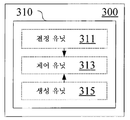
전술한 문제점을 고려하여, 실시예에 따른 무선 통신용 전자 디바이스는 스케줄링 할당 시그널링의 송신 방식 및/또는 내용을 결정하도록 추가로 구성된다. 도 3에 도시된 바와 같이, 전자 디바이스(300)는 결정 유닛(311) 및 제어 유닛(313)을 포함하는 처리 회로(310)를 포함한다.In view of the above problems, the electronic device for wireless communication according to the embodiment is further configured to determine the transmission scheme and / or the content of the scheduling assignment signaling. As shown in FIG. 3, the
결정 유닛(311)은, 동일한 서브프레임에서 송신될 송신 블록들에 따라, 서브프레임에 대한 스케줄링 할당 시그널링의 송신 방식 및/또는 내용을 결정하도록 구성된다.The determining unit 311 is configured to determine, according to transmission blocks to be transmitted in the same subframe, a transmission scheme and / or content of scheduling assignment signaling for the subframe.
도 1 및 도 2를 참조하여 이전에 설명된 대응하는 유닛들의 기능들에 더하여, 제어 유닛(313)은 결정된 바와 같이 스케줄링 할당 시그널링을 송신하기 위한 제어를 수행할 수 있다.In addition to the functions of the corresponding units previously described with reference to FIGS. 1 and 2, the
구체적으로, 스케줄링 할당 시그널링의 송신 방식은: 제1 송신 시간 간격과 동일한 길이를 갖는 하나의 스케줄링 할당 시그널링을 송신하는 것; 제1 송신 시간 간격과 동일한 길이를 갖는 하나의 스케줄링 할당 시그널링 및 서브프레임에서의 송신 블록들의 짧은 송신 시간 간격들에 제각기 대응하는 길이들을 갖는 n개의 스케줄링 할당 시그널링을 송신하는 것; 또는 제1 송신 시간 간격과 동일한 길이를 갖는 n개의 스케줄링 할당 시그널링을 송신하는 것 - n은 서브프레임에서의 송신 블록들의 수임 - 을 포함한다.Specifically, the transmission scheme of the scheduling assignment signaling includes: transmitting one scheduling assignment signaling having a length equal to the first transmission time interval; Transmitting one scheduling allocation signaling having a length equal to the first transmission time interval and n scheduling allocation signaling having lengths corresponding respectively to the short transmission time intervals of the transmission blocks in the subframe; Or transmitting n scheduling assignment signaling having a length equal to the first transmission time interval, where n is the number of transmission blocks in the subframe.
실시예에 따르면, 스케줄링 할당 시그널링은 SCI 포맷(Sidelink Control Information format)에 의해 실현될 수 있고, 결정 유닛(311)은 송신 자원에 관련된 정보를 SCI 포맷의 예약 비트에 추가하도록 추가로 구성될 수 있다.According to an embodiment, the scheduling assignment signaling can be realized by the SCI format (Sidelink Control Information format), and the determining unit 311 can be further configured to add information related to the transmission resource to the reserved bit of the SCI format. .
예를 들어, 결정 유닛(311)은 송신 자원에 관련된 정보를 스케줄링 할당 시그널링의 예약 비트에 추가하도록 구성될 수 있고; 및 제어 유닛(313)은 추가된 정보의 정의를 시스템 정보 블록에서 사용자 장비에 통지하기 위한 제어를 수행할 수 있다.For example, the determining unit 311 may be configured to add the information related to the transmission resource to the reserved bit of the scheduling assignment signaling; And the
다음으로, 스케줄링 할당 시그널링의 송신 방식 및/또는 내용을 결정하는 특정 방식이 특정 예와 조합하여 설명될 것이다. 다음의 예에서의 구체적인 세부사항들은 단지 예시적인 것이고 제한적이지 않다는 것을 이해해야 한다.Next, a specific manner of determining the transmission scheme and / or content of the scheduling assignment signaling will be described in combination with a specific example. It should be understood that the specific details in the following examples are merely exemplary and not limiting.
sTTI로 송신을 수행하는 R15 차량들은 페어링 후에 하나의 서브프레임에서 송신을 수행할 것이고, 이는 시간 자원들의 단편화 및 S-RSSI 결과들에서의 부정확성과 관련한 문제들을 해결할 것이다. 또한, R14 차량이 짧은 SA들을 디코딩할 수 없다는 문제를 해결하기 위해, 페어링된 사용자들은, 예를 들어, SCI 포맷 1을 채택함으로써, R14 SA들의 포맷으로, 하나의 서브프레임인 길이를 갖는 적어도 하나의 SA를 송신할 필요가 있다. 또한, 구현을 위한 새로운 SCI 포맷을 추가하는 방식을 채택할 수 있다는 것을 이해할 수 있을 것이다.R15 vehicles performing transmission with sTTI will perform transmission in one subframe after pairing, which will solve problems related to fragmentation of time resources and inaccuracy in S-RSSI results. In addition, to solve the problem that the R14 vehicle cannot decode short SAs, paired users are at least one having a length that is one subframe, in the format of R14 SAs, for example, by adopting
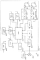
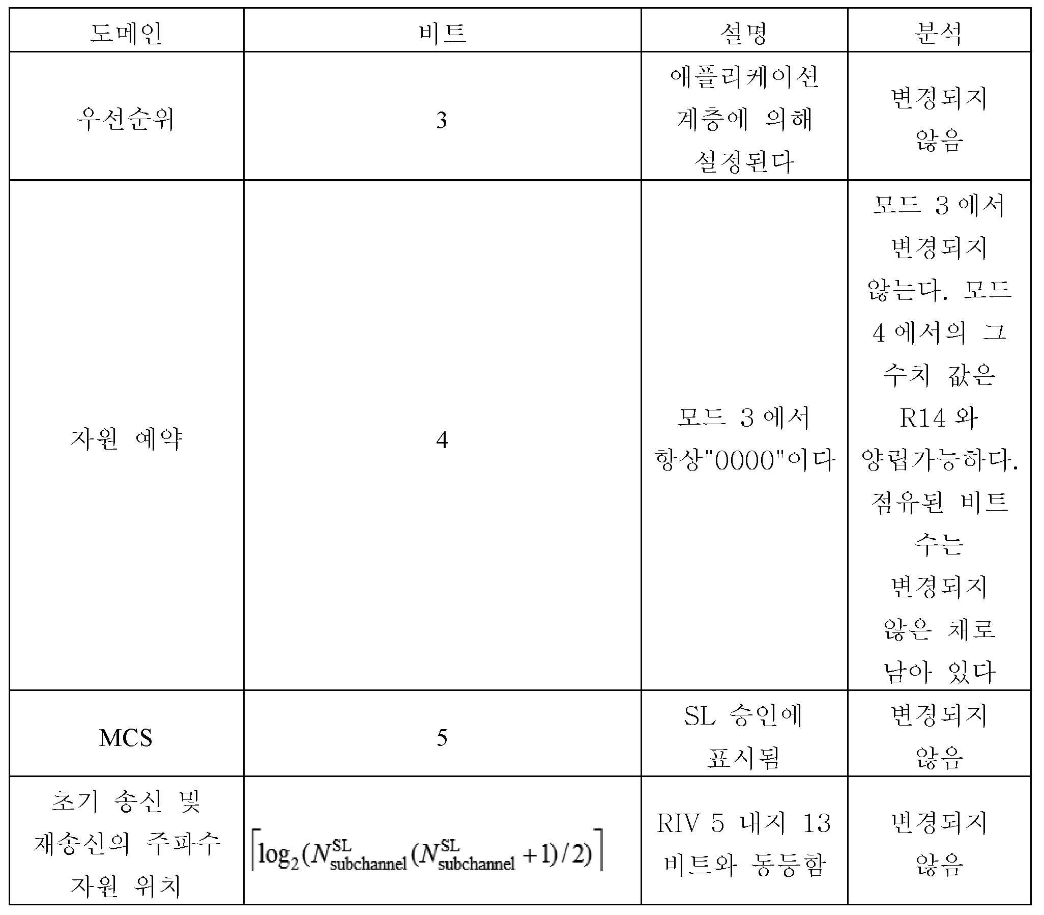
첫번째로, SCI 포맷 1의 각각의 도메인에서의 내용, 즉 분석은 하기 표 1에 나타낸 바와 같다.First, the content, ie analysis, in each domain of
2명의 페어링된 사용자에 대해 SA들에 포함될 필요가 있는 정보 사이의 차이에 따르면, 다음의 3개의 스킴이 예시적인 실시예들로서 제공된다: According to the difference between the information that needs to be included in SAs for two paired users, the following three schemes are provided as exemplary embodiments:
스킴 1: 하나의 재설계된 전통적인 SA를 송신Scheme 1: send one redesigned traditional SA
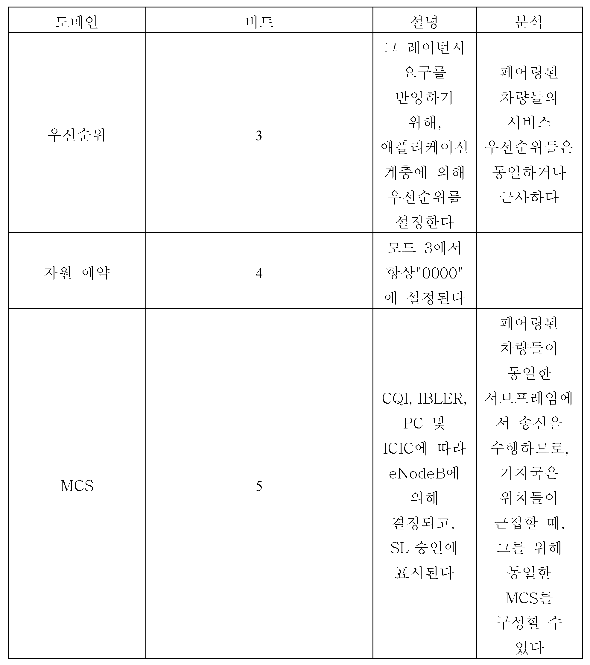
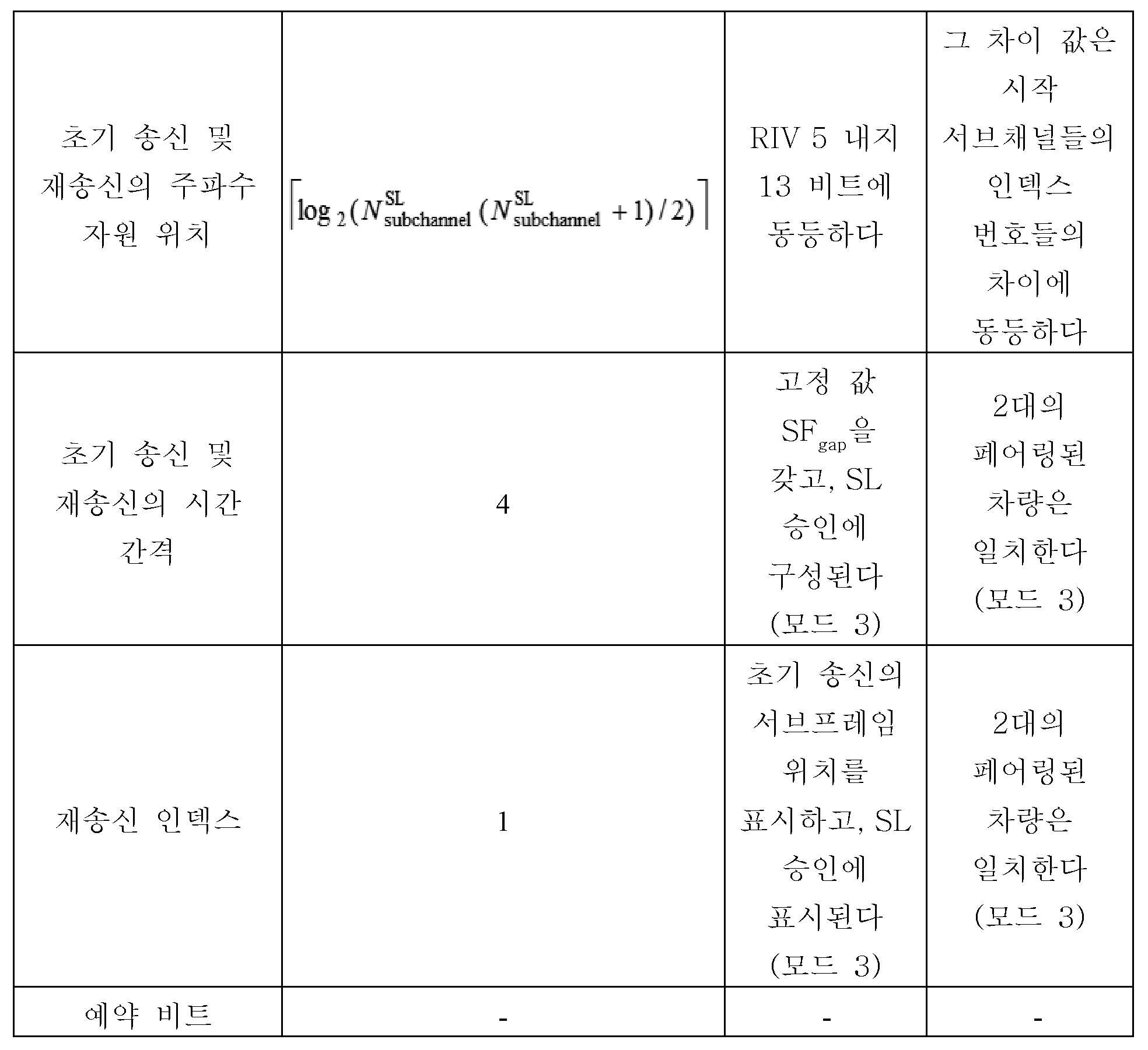
페어링 메커니즘에서, 2개의 페어링된 sTTI 송신이 동일한 VUE로부터 오거나, 또는 페어링된 차량들이 가까운 위치에 있고 동시에 송신을 수행한다면, 예를 들어, 차량 큐 멤버들, 협력 주행 차량들 및 그와 유사한 것, 2개의 페어링된 차량의 SA 내용은 매우 유사할 것이다. 표 1의 분석을 통해, 두 개가 가질 수 있는 배타적 차이는 도메인 "초기 송신 및 재송신의 주파수 자원 위치"에서 나타날 수 있고, 이 도메인 값의 계산 방법은 다음과 같다:In a pairing mechanism, if two paired sTTI transmissions are from the same VUE, or if the paired vehicles are in close proximity and perform transmissions simultaneously, for example, vehicle queue members, cooperating driving vehicles and the like, The SA content of the two paired vehicles will be very similar. Through the analysis of Table 1, the exclusive difference that the two can have can be seen in the domain "Frequency Resource Location of Initial Transmission and Retransmission", and the calculation method of this domain value is as follows:
여기서 NsubCH는 상위 계층 파라미터 numSubchannel-r14에 의해 결정되는 자원 풀에서의 모든 서브채널들의 수이다.Here, N subCH is the number of all subchannels in the resource pool determined by the higher layer parameter numSubchannel-r14.
메시지 크기 면에서 근사하다는 것은 페어링된 대상들의 선발 기준 중 하나이다. 이런 점이 충족될 때, 2대의 차량은 동일한 수의 서브채널들로 할당될 것이고, 그 후 도메인 "초기 송신 및 재송신의 주파수 자원 위치"에서의 페어링된 차량들의 값들은 어떤 차이도 갖지 않거나, 시작 서브채널의 인덱스 번호 ![]()
![]()
![]()
![]()
이 때, 2대의 페어링된 차량은 도 14에 도시된 바와 같이 하나의 전통적인 SA만을 송신할 필요가 있다. SA의 내용은 표 2에 도시된 바와 같다.At this time, two paired vehicles need to transmit only one traditional SA, as shown in FIG. The contents of the SA are shown in Table 2.


스킴 2: 하나의 재설계된 전통적인 SA 및 2개의 짧은 SA를 송신한다.Scheme 2: Send one redesigned traditional SA and two short SAs.
실제 인지 측정에서, 모드 4 차량들은 SCI 포맷 1에서의 하기 3개의 도메인의 내용만을 필요로 한다: 우선순위; 초기 송신 및 재송신의 주파수 자원 위치; 자원 예약(모드 4만).In the actual cognitive measurement,
따라서, 2명의 페어링된 사용자의 3개의 도메인이 (스킴 1에 도시된 바와 같이) 하나의 전통적인 SA에서 설명될 수 있는 한, R14 차량에 대해, 하나의 전통적인 SA가 인지 동작을 수행하기에 충분하였다.Thus, as long as three domains of two paired users can be described in one traditional SA (as shown in Scheme 1), for a R14 vehicle, one traditional SA was sufficient to perform a cognitive operation. .
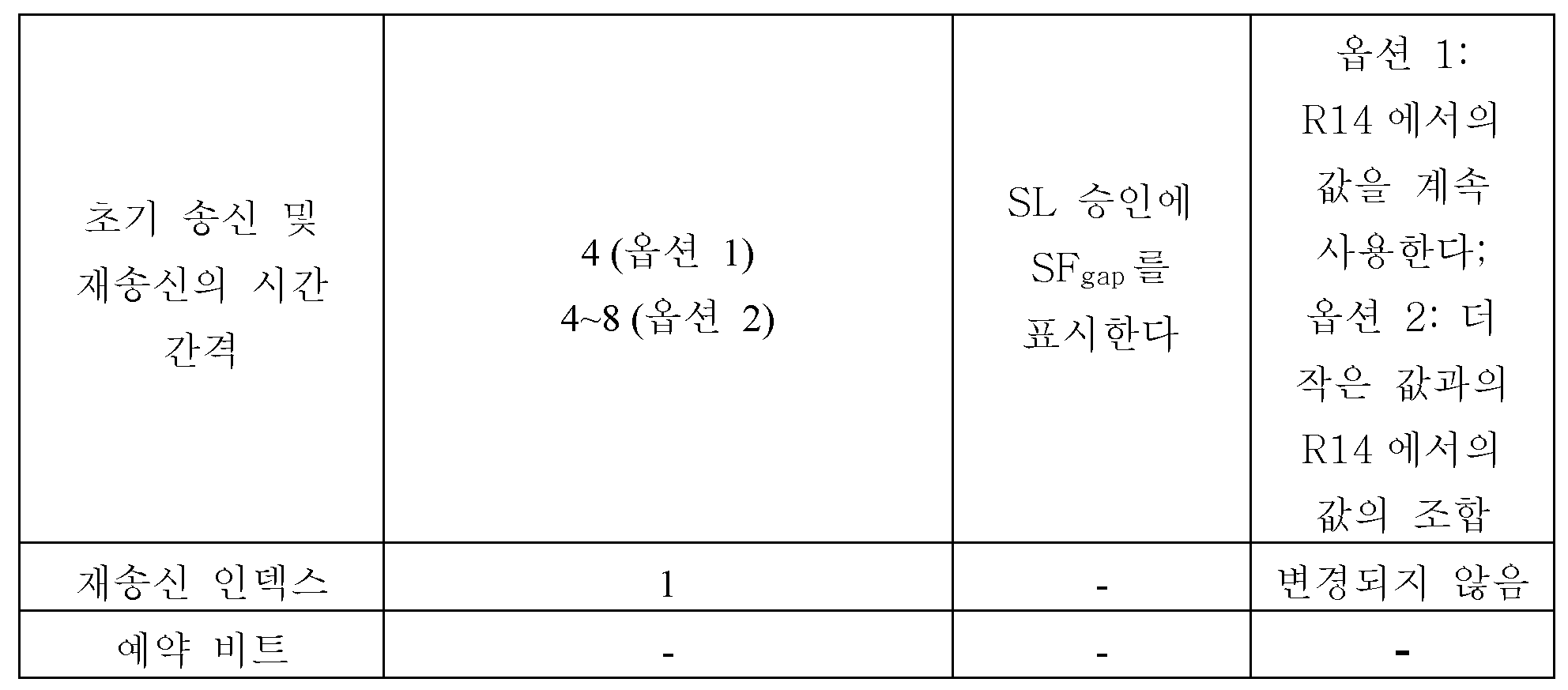
그러나, 페어링된 차량들이 또한 다른 도메인들에서 차이들을 갖는다면, 수신 당사자가 연관된 데이터를 성공적으로 디코딩할 수 있도록 하기 위해, 페어링된 차량들 각각은 도 15에 도시된 바와 같이, 하나의 추가적인 짧은 SA를 송신할 필요가 있다. 짧은 SA들은 R15 차량들에 특정적인 SA들이고, R14 차량들에 의해 디코딩될 필요가 없다. R14 SA들에 대하여, sTTI의 도입만이 고려된다면, 송신의 시간 세분성(granularity)이 절반만큼 감소되고, 그 후 어떤 다른 도메인의 추가도 필요하지 않다; 그러나, 일부 도메인들에서의 내용이 R14 SA들에 기초하여 일부 변경들을 가질 것이고, 내용에서의 변경들에 따라, 그것의 비트 수들은 또한 변경될 수 있으며, 이는 구체적으로 표 3에 도시된 바와 같다.However, if the paired vehicles also have differences in other domains, each paired vehicle has one additional short SA, as shown in FIG. 15, to enable the receiving party to successfully decode the associated data. You need to send a. Short SAs are SAs specific to R15 vehicles and do not need to be decoded by R14 vehicles. For R14 SAs, if only the introduction of sTTI is considered, then the time granularity of the transmission is reduced by half, then no addition of any other domain is needed; However, the content in some domains will have some changes based on the R14 SAs, and depending on the changes in the content, its bit numbers may also change, as is specifically shown in Table 3 .

스킴 3: 그 길이가 제각기 TTI인 2개의 SA를 송신한다.Scheme 3: Transmit two SAs whose lengths are each TTI.
스킴 2의 섹션과는 상이하게, 페어링 차량들의 인지 동작들에 필수적인 내용이 하나의 전통적인 SA에 배치될 수 없는 경우(이러한 상황은 일반적으로 페어링 가능한 R15 차량들이 희소하거나 또는 페어링이 모드 4 차량들 사이에서 발생하는 시나리오에서 발생함), 2개의 차량이 제각기 SA들을 제각기 송신할 필요가 있고, 하위 호환성(backward compatibility)을 충족시키기 위해, SA들은 SCI 포맷 1과 동일한 포맷으로 될 것이고 TTI로 송신될 것이다.Unlike the section of
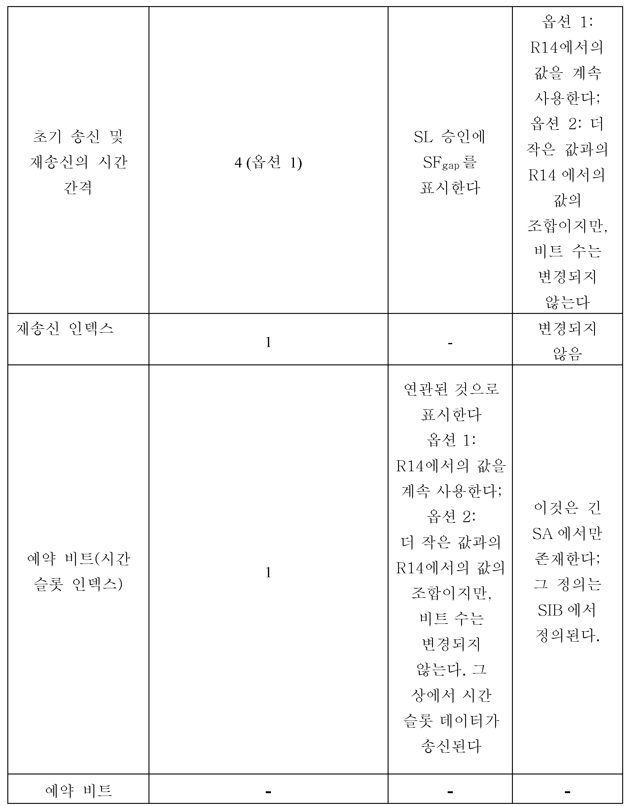
이러한 SA들이 TTI로 송신되기는 하지만, R15 수신기가 디코딩에 필요한 정보를 획득하도록 하기 위해서, 그러한 SA들의 내용은 전통적인 TTI의 것과 구별되지만, 제각기 도메인들에 의해 점유된 비트 수들은 변하지 않는다. 한편, 이러한 SA들의 내용은 짧은 SA들의 내용과 동일하지만, 그것의 비트 수는 특정 차이를 가질 수 있다. 게다가, 2개의 SA가 둘 다 동일한 서브프레임상에서 송신되고 모두 TTI로 송신되기 때문에, 어느 시간 슬롯들이 SA들에 의해 제각기 표시되는지를 구별하기 위해서, 예약 비트에서 1 비트를 점유하는 "타임 슬롯 인덱스"를 추가하는 것이 필요하다. 본 스킴에서, 이러한 SA들은 긴 SA들로 불려지고, 특정 내용은 표 4에 도시된 바와 같다. 표 내의 이탤릭체 부분은 인지 동작에 필수적인 도메인이며, 그 비트 수 및 내용은 R14와 호환가능할 것이다.Although these SAs are transmitted in the TTI, in order for the R15 receiver to obtain the information needed for decoding, the contents of those SAs are distinguished from those of the traditional TTI, but the number of bits occupied by the respective domains does not change. On the other hand, the contents of these SAs are the same as the contents of short SAs, but the number of bits thereof may have a specific difference. In addition, since both SAs are transmitted on the same subframe and both are transmitted in TTI, a "time slot index" that occupies one bit in the reservation bit to distinguish which time slots are individually indicated by the SAs. It is necessary to add In this scheme, these SAs are called long SAs, and specific contents are shown in Table 4. The italic part in the table is a domain that is essential for cognitive operation and its number and content of bits will be compatible with R14.
다음으로, SA 스킴의 선택 및 표시의 예들이 설명될 것이다. 하나의 R15 차량에 대해, 이벤트가 트리거되지 않은 경우에 하나의 짧은 SA를 주도적으로 송신하는 스킴과 함께, 총 4개의 가능한 SA 송신 방식, 즉, 상기 제안된 3개의 스킴이 있다.
모드 3의 경우에, 기지국은 페어링된 사용자들에 대한 SA 송신 스킴을 선택하고, 누구에 의해 SA가 송신되는지를 결정하고, 이들 정보는 SL(sidelink) 승인에서 페어링된 사용자들에게 통지될 것이다. SL 승인에서 2 비트를 점유하는 "SA 인덱스"가 정의되고, 그 의미는 표 5에 도시된 바와 같다. 모드 4의 경우, SA를 송신하는 방식은 페어링 상호작용 프로세스에서의 당사자들 둘 다의 정보 사이의 차이에 따라 페어링된 사용자들에 의해 주도적으로 결정된다.Next, examples of selection and display of the SA scheme will be described. For one R15 vehicle, there are a total of four possible SA transmission schemes, i.
In the case of

도 3의 예시를 계속하면, 실시예에 따르면, 제어 회로(310)는 사용자 장비에 스케줄링 할당 시그널링의 송신 방식을 표시하기 위한 표시 정보를 생성하도록 구성된 생성 유닛(315)을 추가로 포함할 수 있다. 예를 들어, 표시 정보는 무선 자원 제어 시그널링 또는 비 액세스 계층 시그널링에 포함될 수 있다. Continuing with the example of FIG. 3, according to an embodiment, the
여전히 R14, R15 차량들을 예로 취하면, 네트워크 커버리지 내의 차량들에 대해, 이벤트가 트리거된 후, 기지국은, 예를 들어, 하나의 표시 비트를 사용하여 R15 차량에 정보를 줄 수 있다. 표시 비트는, RRC 또는 NAS 등과 같은 시그널링을 포함하지만 이에 제한되지는 않는 시스템 제어 시그널링에 추가될 수 있다. 표시 비트는 RRC 시그널링을 예로서 취함으로써 이하에서 정의된다.Still taking R14, R15 vehicles as an example, for vehicles in network coverage, after the event is triggered, the base station can inform the R15 vehicle, for example using one indication bit. The indication bit may be added to system control signaling, including but not limited to signaling such as RRC or NAS. The indication bit is defined below by taking RRC signaling as an example.
송신을 수행하기 위해 sTTI를 적용하는 R15 차량에 대해, 표시 비트는 다음과 같이 정의될 수 있다:For an R15 vehicle that applies sTTI to perform transmission, the indication bit can be defined as follows:
표시 비트는 "조정 인덱스"라고 명명되고, RRC 시그널링에서 1 비트를 점유하고, R15 차량이 현재 자원 풀에서의 sTTI로 SA 및 데이터를 주도적으로 송신할 수 있는지를 통지한다.The indication bit is named "Adjustment Index" and occupies one bit in RRC signaling and notifies whether the R15 vehicle can dominantly transmit SA and data to the sTTI in the current resource pool.
예를 들어, "조정 인덱스"가 "0"에 설정되는 경우, R15 차량은 sTTI로 SA 및 데이터를 주도적으로 송신할 수 있고; 및 "조정 인덱스"가 "1"에 설정되는 경우, 전술한 바와 같은 실시예에서의 메커니즘이 자원 (재)선택/할당 및 SA 송신에서 채택될 것이다.For example, when the "coordination index" is set to "0", the R15 vehicle can dominantly transmit SA and data to the sTTI; And when the "coordination index" is set to "1", the mechanism in the embodiment as described above will be adopted in resource (re) selection / allocation and SA transmission.
R14 및 R15가 일부 자원 풀들에서만 공존할 것이라면, "조정 인덱스"의 수치 값들은 R15에 특정적인 자원 풀들에서 항상 "0"일 수 있고, R15 차량이 공유 자원 풀들에 진입한 후에만, 표시 비트의 수치 값들은 이벤트가 트리거된 후에 변경될 것이라는 점에 유의해야 한다.If R14 and R15 will coexist only in some resource pools, the numeric values of the "coordination index" may always be "0" in resource pools specific to R15, and only after the R15 vehicle enters shared resource pools, Note that the numeric values will change after the event is triggered.
다음으로, 또 다른 실시예에 따른 무선 통신을 위한 전자 디바이스가 도 4를 참조하여 설명될 것이다. 도 4에 도시된 바와 같이, 본 실시예에 따른 전자 디바이스(400)는 결정 유닛(411) 및 제어 유닛(413)을 포함하는 처리 회로(410)를 포함한다.Next, an electronic device for wireless communication according to another embodiment will be described with reference to FIG. 4. As shown in FIG. 4, the
결정 유닛(411)은, 사용자 장비가 제1 송신 시간 간격보다 작은 짧은 송신 시간 간격으로 근접-기반 서비스 통신을 수행하는 경우에, 제1 송신 시간 간격과 동일한 길이를 갖는 하나의 스케줄링 할당 시그널링을 적어도 포함하는 스케줄링 할당 시그널링을 결정하도록 구성된다.The determining
제어 유닛(413)은, 동일한 서브프레임에서, 짧은 송신 시간 간격을 각각 갖는 적어도 2개의 송신 블록을 송신하기 위한 제어를 수행하도록 사이드링크 승인을 수행하게 구성되고, 여기서 서브프레임의 길이는 제1 송신 시간 간격과 동일하다.The
다음으로, 도 11을 참조하여, 상기 제각기 실시예와 관련한 전체적인 프로세스 예가 VUE들을 예로서 취하여 설명될 것이다.Next, referring to FIG. 11, an overall process example in connection with each of the above embodiments will be described taking VUEs as an example.
먼저, 트리거 조건의 모니터링이 기지국 측에서 수행되고; 또한, 사용자 장비는 미리 결정된 조건에 기초하여 기지국에 보고하는 것을 수행할 수 있다.First, monitoring of the trigger condition is performed at the base station side; In addition, the user equipment may perform reporting to the base station based on the predetermined condition.
이벤트 트리거 조건이 충족될 때, 기지국은, 예를 들어, "조정 인덱스"에 의해, 사용자 장비에게 대응하는 조정 메커니즘을 채택하도록 통지할 수 있다.When the event trigger condition is met, the base station may notify the user equipment to adopt the corresponding coordination mechanism, for example by means of a "coordination index".
모드 3 R15 사용자 장비에 대해, 이것은 기지국으로부터 사이드링크 자원들을 요청하고, 기지국은 페어링 방식 등을 결정하고, 사이드링크 승인을 수행한다.For
모드 4 R15 사용자 장비에 대해, 이것은 페어링을 주도적으로 수행할 수 있다.For
다음으로, 사용자 장비의 페어링의 예시적인 프로세스가 설명될 것이다.Next, an example process of pairing of user equipment will be described.
먼저, 모드 3 차량에 대한 페어링 메커니즘이 설명될 것이다. 모드 3 차량에 대한 자원들을 스케줄링하는 프로세스에서, 기지국은 페어링 메커니즘을 구현할 것이다.First, the pairing mechanism for the
구체적으로, 다음의 단계들이 포함될 수 있다:Specifically, the following steps may be included:
먼저, 자원들을 신청할 때, 모드 3 차량은 RRC의 도메인 "SidelinkUEInformation"에서 수신 당사자 ID를 업로드하고, 도메인 "UEAssistanceInformation"에서 우선 순위(PPPP)를 업로드하고, IE LocationInfo에서의 상세한 지리적 위치 정보를 업로드하고, BSR 제어 유닛에서 그 송신에 필요한 자원들의 크기를 표시할 수 있다.First, when applying for resources, the
다음으로, 기지국은, 차량에 의해 업로드된 정보에 따라, 자원들을 동시에 신청하는 차량들에 대한 페어링을 수행할 것이고, 그 기본적인 페어링 원리는 높은 유사성을 갖는 차량들이 최대한도로 페어링된 차량들이 되게 하는 것이다. R15 VUE의 송신에 필요한 다수의 연속적인 sTTI가 짝수이면, 페어링을 수행하는 것은 불필요하다.Next, the base station will perform pairing for vehicles that simultaneously apply for resources according to the information uploaded by the vehicle, and its basic pairing principle is to ensure that vehicles with high similarity are the best paired vehicles. . If the number of consecutive sTTIs required for transmission of the R15 VUE is even, it is not necessary to perform pairing.
그러면, 기지국은 서브프레임을 세분성으로서 취함으로써 페어링 차량들에 대해 자원들을 할당하고, 어느 타임 슬롯들에서 그 둘이 제각기 송신을 수행하는지를 표시한다. The base station then allocates resources for the pairing vehicles by taking the subframe as granularity and indicates in which time slots the two perform transmission respectively.
페어링된 송신의 목적은 2개의 독립적인 sTTI가 하나의 서브프레임에서 송신되도록 야기하는 것이며, 이는 R14 차량의 관점에서, 하나의 R14 서브프레임에서 하나의 TTI를 송신하는 것과 동일하다. 따라서, 페어링의 원리는 페어링된 사용자들이 송신 전력, 점유된 자원 위치 및 크기 면에서, 최대한도로 서로 근사하도록 야기하는 것이다.The purpose of the paired transmission is to cause two independent sTTIs to be transmitted in one subframe, which is equivalent to transmitting one TTI in one R14 subframe, from the perspective of the R14 vehicle. Thus, the principle of pairing is to cause paired users to be as close to each other as possible, in terms of transmit power, occupied resource location and size.
이전에 언급된 바와 같이, 페어링 기준에서, 우선순위는 가장 중요한 인자인데, 그 이유는, (차량의 V2X 서비스 타입에 의해 결정되는) 고정된 수치 값을 가지며, 송신 전력의 크기뿐만 아니라 업링크 송신과의 사이드링크 송신의 충돌의 경우에 처리 방식을 결정하기 때문이다. 동일한 서브프레임에서 송신을 수행하는 2명의 사용자에 대해, 첫번째로 이들이 동일한 서비스 우선 순위를 갖는 것을 보장하는 것이 필요하고; 두번째로, 그 둘이 요청들을 송신하는 시간들이 매우 가깝기 때문에 이들이 가까운 지리적 위치들에 있고, 게다가 동일한 자원 풀에서 MCS의 결정 요인들이 주로 채널 품질 및 비트 에러 레이트이고, 이 경우에, 기지국이 가까운 지리적 위치들에서 사용자들에 대해 동일한 MCS를 선택할 수 있는 것을 보장하는 것이 필요하고; 마지막으로, 그 둘의 메시지 크기들이 근사하고, 2개의 메시지 크기가 근사할 때 그리고 이 둘의 MCS들이 동일한 경우에, 기지국이 2명의 페어링된 사용자에 대해 동일한 수의 서브채널을 할당할 수 있는 것을 보장하는 것이 필요하다. 페어링된 차량들을 선택하는 3가지 기준의 우선순위들은 높은 것에서 낮은 것으로 서비스 우선 순위, 지리적 위치, 및 메시지 크기일 수 있다.As mentioned previously, in the pairing criteria, priority is the most important factor, because it has a fixed numerical value (determined by the vehicle's V2X service type) and uplink transmission as well as the magnitude of the transmit power. This is because the processing method is determined in the case of a collision of the sidelink transmission with the network. For two users performing transmissions in the same subframe, it is first necessary to ensure that they have the same service priority; Second, they are in close geographic locations because the times they are sending requests are very close, and furthermore, the determinants of MCS in the same resource pool are mainly channel quality and bit error rate, in which case the base station is close to geographic location. Need to ensure that the same MCS can be selected for the users in the network; Finally, when the two message sizes are approximate, when the two message sizes are approximate, and when both MCSs are the same, the base station can allocate the same number of subchannels for the two paired users. It is necessary to guarantee. The priority of the three criteria for selecting paired vehicles may be from high to low, service priority, geographic location, and message size.
페어링 메커니즘은, 자원들을 할당하기 전에, 송신을 동시에 수행하는 차량들의 정보를 비교하여, 사이드링크 송신이 하나의 서브프레임을 최대한도로 채우고, 페어링된 사용자들의 송신 정보가 크게 달라지지 않도록 할 필요가 있다. 따라서, 중앙 제어된 스케줄링 방식인 모드 3이 페어링 메커니즘에 더 적합하지만, 페어링 메커니즘은 또한 모드 4 사용자 장비에 대해 이용될 수 있다.The pairing mechanism needs to compare the information of the vehicles performing the transmission at the same time before allocating resources, so that the sidelink transmission fills one subframe to the maximum and the transmission information of the paired users does not vary significantly. . Thus, although
다음으로, 모드 4 차량에 대한 페어링 메커니즘의 예에 대해서 설명한다.Next, an example of a pairing mechanism for a
모드 4 차량이 페어링 메커니즘을 채택하는 시나리오에서, 특정 흐름은 다음과 같이 개략적으로 기술될 수 있다:In a scenario where a
먼저, 차량은 주변 차량들에 페어링 요청을 브로드캐스팅하고, 페어링 가능한 R15 모드 4 차량들은 요청에 응답할 것이다.First, the vehicle broadcasts a pairing request to surrounding vehicles, and
다음으로, 통신 범위 내의 페어링 가능한 차량들은, 페어링 가능한 차량 그룹에 있어서, 우선순위, 지리적 위치, 통신처, 메시지 크기 및 자원 예약에 대한 정보를 포함하여, 그 송신 정보를 멀티캐스팅한다.Next, pairable vehicles within the communication range multicast the transmission information, including information about priority, geographic location, communication destination, message size, and resource reservation, in the pairable vehicle group.
다음으로, 차량은 전술한 실시예에서의 것과 유사한 방식으로, 페어링을 수행하기 위한 적합한 차량을 선택할 것이다. 페어링된 차량들은 그 둘의 인지 결과들을 합성할 수 있고, 송신 자원들 및 SA 송신 스킴들을 선택할 수 있다.Next, the vehicle will select a suitable vehicle for performing pairing in a manner similar to that in the above-described embodiment. The paired vehicles can synthesize the two recognition results and select transmission resources and SA transmission schemes.
모드 4 차량에 대한 페어링의 예시적인 프로세스는 도 13에 도시된 바와 같다.An example process of pairing for a
무선 통신을 위한 전자 디바이스들의 실시예들이 위에서 설명되었다. 또한, 본 발명은 전술한 실시예들에 따른 송수신기 디바이스 및 전자 디바이스들을 포함할 수 있는 대응하는 무선 통신 장치들을 추가로 포함한다.Embodiments of electronic devices for wireless communication have been described above. In addition, the present invention further includes corresponding wireless communication devices, which may include transceiver devices and electronic devices according to the embodiments described above.
또한, 본 발명의 실시예들에 따른 디바이스들 및 장치들의 전술한 설명에서, 일부 방법들 및 프로세스들이 명확히 개시되었다. 다음으로, 본 발명의 실시예에 따른 무선 통신 방법의 설명은 앞에서 설명된 상세 사항을 반복하지 않고 주어질 것이다.In addition, in the foregoing description of devices and apparatuses in accordance with embodiments of the present invention, some methods and processes have been clearly disclosed. Next, a description of a wireless communication method according to an embodiment of the present invention will be given without repeating the details described above.
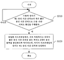
도 5에 도시된 바와 같이, 본 실시예에 따른 무선 통신 방법에서, 사용자 장비가 제1 송신 시간 간격보다 작은 짧은 송신 시간 간격으로 근접-기반 서비스 통신을 수행하는 경우(S510에서 Y), 동일한 서브프레임에서, 서로 독립적이고 각각이 짧은 송신 시간 간격을 갖는 적어도 2개의 송신 블록을 송신하도록 야기되는데(S520), 여기서, 서브프레임의 길이는 제1 송신 시간 간격과 동일하다.As shown in FIG. 5, in the wireless communication method according to the present embodiment, when the user equipment performs proximity-based service communication at a short transmission time interval smaller than the first transmission time interval (Y in S510), the same sub In the frame, it is caused to transmit at least two transmission blocks independent of each other and each having a short transmission time interval (S520), where the length of the subframe is equal to the first transmission time interval.
전술한 실시예들은 자원들이 기지국에 의해 스케줄링되고 자원들을 자율적으로 선택하는 차량들에 대한 페어링 메커니즘들에 관한 것이다. 전자의 경우, eNodeB는 복수의 독립적인 sTTI 송신에 대해 자원들을 집중적으로 스케줄링하고; 그리고 후자에 대해, 차량은 주변 차량들과 상호작용할 것이고, 페어링 가능 차량들은 페어링된 송신을 수행하기 위한 적절한 차량을 선택하기 위해서, 범위 내에서 자신들의 송신 정보를 멀티캐스팅할 것이다.The above embodiments relate to pairing mechanisms for vehicles in which resources are scheduled by a base station and autonomously select resources. In the former case, the eNodeB intensively schedules resources for a plurality of independent sTTI transmissions; And for the latter, the vehicles will interact with the surrounding vehicles and the pairable vehicles will multicast their transmission information within range to select the appropriate vehicle to perform the paired transmission.
다음으로, 본 발명의 실시예들에 따른 사용자 장비 측을 위한 전자 디바이스들의 구성 예들이 앞서 설명한 상세 사항들을 반복하지 않고 설명될 것이다.Next, configuration examples of electronic devices for the user equipment side according to embodiments of the present invention will be described without repeating the above-described details.
도 6에 도시된 바와 같이, 실시예에 따른 사용자 장비 측을 위한 전자 디바이스(600)는 처리 회로(610)를 포함한다. 처리 회로(610)는 수신 제어 유닛(611) 및 송신 제어 유닛(613)을 포함한다.As shown in FIG. 6, the
본 실시예는 짧은 송신 시간 간격을 사용하는 사용자 장비(예를 들어, 모드 3 R15 VUE)에 대응한다.This embodiment corresponds to user equipment (eg,
수신 제어 유닛(611)은 제어 노드로부터 표시 정보를 수신하기 위한 제어를 수행하도록 구성된다. 제어 노드는, 예를 들어, 기지국, RSU 또는 또 다른 사용자 장비를 포함할 수 있다.The
송신 제어 유닛(613)은, 사용자 장비가 제1 송신 시간 간격보다 작은 짧은 송신 시간 간격으로 근접-기반 서비스 통신을 수행하는 경우에, 사용자 장비의 송신 블록이 짧은 송신 시간 간격을 갖는 또 다른 송신 블록과 동일한 서브프레임에서 송신되도록 표시 정보에 기초하여 제어를 수행하도록 구성되고, 여기서 서브프레임의 길이는 제1 송신 시간 간격과 동일하다.The
"짧은 송신 시간 간격을 갖는 또 다른 송신 블록"은 현재 사용자 장비의 송신 블록 또는 또 다른 사용자 장비의 송신 블록을 포함할 수 있다."Another transmission block with a short transmission time interval" may include a transmission block of the current user equipment or a transmission block of another user equipment.
도 7에 도시된 바와 같이, 실시예에 따른 사용자 장비 측을 위한 전자 디바이스(700)는 처리 회로(710)를 포함한다. 처리 회로(710)는 수신 제어 유닛(711)을 포함한다. 선택적으로, 처리 회로(710)는 보고 제어 유닛(713)을 추가로 포함할 수 있다.As shown in FIG. 7, an
본 실시예는 긴 송신 시간 간격을 사용하는 사용자 장비(예를 들어, 모드 3 R14 VUE)에 대응한다.This embodiment corresponds to user equipment (eg,
수신 제어 유닛(711)은, 사용자 장비가 제1 송신 시간 간격으로 근접-기반 서비스 통신을 수행하는 경우에, 동일한 서브프레임에서 송신되고 또한 서로 독립적이고 각각이 제1 송신 시간 간격보다 작은 짧은 송신 시간 간격을 갖는 적어도 2개의 송신 블록과 연관된 스케줄링 할당 시그널링을 수신하기 위한 제어를 수행하도록 구성되고, 서브프레임의 길이는 제1 송신 시간 간격과 동일하다.The
또한, 수신 제어 유닛(711)은 또한 송신 블록들에 대한 인지 측정을 수행하기 위한 제어를 수행하도록 또한 구성될 수 있다.In addition, the
보고 제어 유닛(713)은 사용자 장비의 송신 실패의 빈도가 미리 결정된 레벨에 도달하는 경우에; 또는 사용자 장비에 의해 수신된 디코딩불가능한 스케줄링 할당 시그널링의 비율이 미리 결정된 레벨에 도달하는 경우에, 대응하는 표시 정보를 제어 노드에 보고하도록 구성된다.The
또한, 본 출원의 실시예들은 사용자 장비 측을 위한 전술한 전자 디바이스들(600, 700)에 대응하는 무선 통신 장치들 및 무선 통신 방법들을 추가로 포함한다.In addition, embodiments of the present application further include wireless communication devices and wireless communication methods corresponding to the aforementioned
또한, 본 출원의 실시예들은, 사용자 장비가 제1 송신 시간 간격보다 작은 짧은 송신 시간 간격과 근접-기반 서비스 통신을 수행하는 경우에, 동일한 서브프레임에서, 서로 독립적이고 짧은 송신 시간 간격을 각각 갖는 적어도 2개의 송신 블록을 송신하기 위한 제어를 수행하도록 구성되는 제어 유닛을 포함하는 무선 통신용 전자 디바이스를 추가로 포함하고, 여기서 서브프레임의 길이는 제1 송신 시간 간격과 동일하다.In addition, embodiments of the present application each have a short transmission time interval independent from each other and in the same subframe, when the user equipment performs short transmission time interval and proximity-based service communication smaller than the first transmission time interval. And further comprising an electronic device for wireless communication comprising a control unit configured to perform control for transmitting at least two transmission blocks, wherein the length of the subframe is equal to the first transmission time interval.
본 출원의 실시예들은 무선 통신을 위한 전자 디바이스를 추가로 포함하고, 이 전자 디바이스는: 사용자 장비가 제1 송신 시간 간격보다 작은 짧은 송신 시간 간격으로 근접-기반 서비스 통신을 수행하는 경우, 제1 송신 시간 간격과 동일한 길이를 갖는 하나의 스케줄링 할당 시그널링을 적어도 포함하는 스케줄링 할당 시그널링을 결정하도록 구성된 결정 유닛; 및 동일한 서브프레임에서, 짧은 송신 시간 간격을 각각 갖는 적어도 2개의 송신 블록을 송신하기 위한 제어를 수행하도록 구성된 제어 유닛 - 서브프레임의 길이는 제1 송신 시간 간격과 동일함 - 을 포함한다. Embodiments of the present application further include an electronic device for wireless communication, the electronic device comprising: if the user equipment performs proximity-based service communication at a short transmission time interval less than the first transmission time interval; A determining unit, configured to determine scheduling allocation signaling comprising at least one scheduling allocation signaling having a length equal to the transmission time interval; And a control unit configured to perform control for transmitting at least two transmission blocks each having a short transmission time interval, in the same subframe, wherein the length of the subframe is equal to the first transmission time interval.
본 출원의 실시예들은 사용자 장비 측을 위한 전자 디바이스를 추가로 포함하고, 이 전자 디바이스는: 제어 노드로부터 표시 정보를 수신하기 위한 제어를 수행하도록 구성된 수신 제어 유닛; 및 사용자 장비가 제1 송신 시간 간격보다 작은 짧은 송신 시간 간격으로 근접-기반 서비스 통신을 수행하는 경우에, 사용자 장비의 송신 블록이 짧은 송신 시간 간격을 갖는 또 다른 송신 블록과 동일한 서브프레임에서 송신되도록 표시 정보에 기초하여 제어를 수행하도록 구성된 송신 제어 유닛 - 서브프레임의 길이는 제1 송신 시간 간격과 동일함 - 을 포함한다.Embodiments of the present application further include an electronic device for the user equipment side, the electronic device comprising: a reception control unit configured to perform control for receiving indication information from a control node; And when the user equipment performs proximity-based service communication at a short transmission time interval smaller than the first transmission time interval, the transmission block of the user equipment is transmitted in the same subframe as another transmission block having a short transmission time interval. A transmission control unit configured to perform control based on the indication information, wherein the length of the subframe is equal to the first transmission time interval.
본 출원의 실시예들은 사용자 장비 측을 위한 전자 디바이스를 추가로 포함하고, 이 전자 디바이스는: 사용자 장비가 제1 송신 시간 간격으로 근접-기반 서비스 통신을 수행하는 경우에, 동일한 서브프레임에서 송신되고, 서로 독립적이고 각각이 제1 송신 시간 간격보다 작은 짧은 송신 시간 간격을 갖는, 적어도 2개의 송신 블록과 연관된 스케줄링 할당 시그널링을 수신하기 위한 제어를 수행하도록 구성되는 제어 유닛을 포함하고, 여기서 서브프레임의 길이는 제1 송신 시간 간격과 동일하다.Embodiments of the present application further include an electronic device for the user equipment side, wherein the electronic device is: transmitted in the same subframe when the user equipment performs proximity-based service communication at a first transmission time interval; And a control unit configured to perform control to receive scheduling assignment signaling associated with at least two transmission blocks independent of each other and each having a short transmission time interval less than the first transmission time interval, wherein The length is equal to the first transmission time interval.
예로서, 상기 방법의 제각기 단계들 및 상기 디바이스들의 제각기 구성 모듈들 및/또는 유닛들은 소프트웨어, 펌웨어, 하드웨어 또는 이들의 조합으로서 구현될 수 있다. 소프트웨어 또는 펌웨어에 의한 구현의 경우에, 상기 방법들을 구현하기 위한 소프트웨어를 구성하는 프로그램은 저장 매체 또는 네트워크로부터 목적-특정적 하드웨어 구조(예를 들어, 도 17에 도시된 범용 컴퓨터(2000))를 갖는 컴퓨터에 설치된다. 컴퓨터는, 다양한 프로그램으로 설치될 때, 다양한 기능 등을 실행할 수 있다.By way of example, each of the steps of the method and respective configuration modules and / or units of the devices may be implemented as software, firmware, hardware or a combination thereof. In the case of an implementation by software or firmware, a program constituting the software for implementing the methods may be used to store an object-specific hardware structure (for example, the
도 17에서, 동작 처리 장치(즉, CPU)(2001)는 ROM(Read-Only Memory)(2002)에 저장된 프로그램 또는 저장부(2008)로부터 RAM(Random Access Memory)(2003)으로 업로드된 프로그램에 따라 다양한 처리를 실행한다. RAM(2003)에서, CPU(2001)가 다양한 처리 등을 실행할 때 필요한 데이터는 또한 필요에 따라 저장된다. CPU(2001), ROM(2002) 및 RAM(2003)은 버스(2004)를 통해 서로 링크된다. 입력/출력 인터페이스(2005)도 버스(2004)에 링크된다.In FIG. 17, an operation processing device (ie, a CPU) 2001 is a program stored in a read-only memory (ROM) 2002 or a program uploaded from a
다음의 컴포넌트들이 입력/출력 인터페이스(2005)에 링크된다: 입력부(2006)(키보드, 마우스 등을 포함함), 출력부(2007)(CRT(Cathode Ray Tube), LCD(Liquid Crystal Display) 등과 같은 디스플레이뿐만 아니라 스피커 등), 저장부(2008)(하드 디스크 등을 포함함), 및 통신부(2009)(LAN 카드, 모뎀 등과 같은 네트워크 인터페이스 카드를 포함함). 통신부(2009)는, 인터넷 등의 네트워크를 통한 통신 처리를 실행한다. 필요에 따라, 드라이버(2010)는 또한 입력/출력 인터페이스(2005)에 링크될 수 있다. 필요에 따라 드라이버(2010)상에 자기 디스크, 광 디스크, 자기 광 디스크, 반도체 메모리 등과 같은 분리가능 매체(2011)가 설치되어, 그로부터 판독된 컴퓨터 프로그램이 필요에 따라 저장부(2008)에 설치되도록 한다.The following components are linked to input / output interface 2005: input 2006 (including keyboard, mouse, etc.), output 2007 (Cathode Ray Tube (CRT), Liquid Crystal Display (LCD), etc.). Display as well as speakers), storage unit 2008 (including hard disks, etc.), and communication unit 2009 (including network interface cards such as LAN cards, modems, etc.). The
상기 일련의 처리가 소프트웨어에 의해 구현되는 경우, 소프트웨어를 구성하는 프로그램은 인터넷과 같은 네트워크 또는 분리가능 매체(2011)와 같은 저장 매체로부터 설치된다.When the above series of processes are implemented by software, the program constituting the software is installed from a network such as the Internet or a storage medium such as a
통상의 기술자는 그러한 저장 매체가 프로그램을 저장하고 있고 도 17에 도시된 바와 같이 프로그램을 사용자에게 제공하기 위한 장치와 별개로 배포되는 분리가능한 매체(2011)로 제한되지 않는다는 것을 알아야 한다. 분리가능 매체(2011)의 예들은 (플로피 디스크(등록 상표)를 포함하는) 자기 디스크, (컴팩트 디스크 판독 전용 메모리(CD-ROM) 및 디지털 다기능 디스크(DVD)를 포함하는) 컴팩트 디스크, (미니 디스크(MD)(등록 상표)를 포함하는) 광자기 디스크, 및 반도체 메모리를 포함한다. 대안적으로, 저장 매체는 ROM(2002)에 포함된 하드 디스크 등, 및 프로그램이 저장되고 이들을 포함하는 장치와 동시에 사용자들에게 분배되는 저장부(2008)일 수 있다.Those skilled in the art should appreciate that such storage media is not limited to
본 발명의 실시예들은 또한 머신에 의해 판독되고 실행될 때, 본 발명의 실시예에 따른 상기 방법을 실행할 수 있는 머신 판독가능 명령어 코드들을 그 안에 저장하는 프로그램 제품에 관한 것이다.Embodiments of the present invention also relate to a program product for storing machine readable instruction codes therein that are capable of executing the method according to an embodiment of the present invention when read and executed by a machine.
따라서, 머신 판독가능 명령어 코드들이 저장된 상기 프로그램 제품을 운반하기 위한 저장 매체도 본 발명의 개시내용에 또한 포함된다. 저장 매체는 플로피 디스크, 광 디스크, 자기 광학 디스크, 메모리 카드, 메모리 스틱 등을 포함하지만, 이들로만 제한되지는 않는다.Thus, a storage medium for carrying the program product having stored machine readable instruction codes is also included in the present disclosure. Storage media include, but are not limited to, floppy disks, optical disks, magneto-optical disks, memory cards, memory sticks, and the like.
본 발명의 실시예들은 또한 전자 장치에 관한 것이다. 전자 장치는, 기지국 측에 사용될 때, 매크로 eNB 및 소형 eNB와 같은, gNB 또는 eNB(Evolved Node B)와 같은 임의 타입의 기지국으로서 실현될 수 있다. 소형 eNB는, 피코 eNB, 마이크로 eNB 및 홈(펨토) eNB와 같은, 매크로 셀보다 작은 셀을 커버하는 eNB일 수 있다. 대안적으로, 전자 장치는, NodeB 및 BTS(Base Transceiver Station)와 같은, 임의의 다른 타입의 기지국으로서 실현될 수 있다. 전자 장치는 무선 통신을 제어하도록 구성된 본체(기지국 장비라고도 함); 및 본체와 상이한 장소들에 배열된 하나 이상의 원격 무선 헤드(RRH)들을 포함할 수 있다. 또한, 후술할 모든 다양한 타입의 단말기들은 기지국 기능들을 일시적으로 또는 반영구적으로 실행하는 기지국들로서 동작할 수 있다.Embodiments of the invention also relate to an electronic device. When used at the base station side, the electronic device may be realized as any type of base station, such as a gNB or an Evolved Node B (eNB), such as a macro eNB and a small eNB. The small eNB may be an eNB covering a cell smaller than a macro cell, such as a pico eNB, a micro eNB, and a home (femto) eNB. Alternatively, the electronic device may be realized as any other type of base station, such as NodeB and Base Transceiver Station (BTS). The electronic device may include a main body (also called base station equipment) configured to control wireless communication; And one or more remote radio heads (RRHs) arranged in different locations from the body. In addition, all of the various types of terminals described below can operate as base stations that temporarily or semi-permanently execute base station functions.
전자 장치는, 사용자 장비 측에 사용될 때, (지능형 전화, 태블릿 개인용 컴퓨터(PC), 노트북 PC, 휴대용 게임 단말기, 휴대용/소프트독(softdog) 모바일 라우터 및 디지털 카메라와 같은) 모바일 단말기 또는 차량 내 단말기(예컨대 자동차 내비게이션 장비)로서 실현될 수 있다. 또한, 전자 장치는 상기 단말기들 각각상에 설치된 (단일 또는 그보다 많은 웨이퍼를 포함하는 집적 회로 모듈과 같은) 무선 통신 모듈일 수 있다.Electronic devices, when used on the user equipment side, are mobile terminals or in-vehicle terminals (such as intelligent telephones, tablet personal computers (PCs), notebook PCs, portable gaming terminals, portable / softdog mobile routers and digital cameras). (For example, car navigation equipment). The electronic device may also be a wireless communication module (such as an integrated circuit module comprising a single or more wafers) installed on each of the terminals.
[단말 장비에 관한 적용예][Application example regarding terminal equipment]
도 18은 본 개시내용의 기술이 적용될 수 있는 지능형 전화(2500)의 개략적인 구성의 예를 도시하는 블록도이다. 지능형 전화(2500)는 프로세서(2501), 메모리(2502), 저장 디바이스(2503), 외부 접속 인터페이스(2504), 카메라(2506), 센서(2507), 마이크로폰(2508), 입력 디바이스(2509), 디스플레이 디바이스(2510), 스피커(2511), 무선 통신 인터페이스(2512), 하나 이상의 안테나 스위치(2515), 하나 이상의 안테나(2516), 버스(2517), 배터리(2518) 및 보조 제어기(2519)를 포함한다.18 is a block diagram illustrating an example of a schematic configuration of an
프로세서(2501)는, 예를 들어, CPU 또는 SoC(System on Chip)일 수 있고, 지능형 전화(2500)의 애플리케이션 계층 및 추가 계층들의 기능들을 제어할 수 있다. 메모리(2502)는 RAM 및 ROM을 포함하고, 프로세서(2501)에 의해 실행되는 데이터 및 프로그램들을 저장한다. 저장 디바이스(2503)는 반도체 메모리 및 하드 디스크와 같은 저장 매체를 포함할 수 있다. 외부 접속 인터페이스(2504)는 외부 디바이스(예컨대, 메모리 카드 및 범용 직렬 버스(USB) 디바이스)를 지능형 전화(2500)의 인터페이스에 접속하기 위해 사용된다.The
카메라(2506)는 이미지 센서(CCD(Charge Coupled Device) 및 CMOS(Complementary Metal Oxide Semiconductor)와 같은 것)를 포함하고, 캡처된 이미지를 생성한다. 센서(2507)는, 측정 센서, 자이로 센서, 지자기 센서, 및 가속도 센서와 같은 센서들의 그룹을 포함할 수 있다. 마이크로폰(2508)은 지능형 전화기(2500)에 입력된 사운드를 오디오 신호로 변환한다. 입력 디바이스(2509)는, 예를 들어, 디스플레이 디바이스(2510)의 스크린상의 터치, 키패드, 키보드, 버튼 또는 스위치를 검출하도록 구성된 터치 센서를 포함하고, 사용자로부터 입력된 조작 또는 정보를 수신한다. 디스플레이 디바이스(2510)는 (액정 디스플레이(LCD) 및 유기 발광 다이오드(OLED) 디스플레이와 같은) 스크린을 포함하고, 지능형 전화(2500)의 출력 이미지를 디스플레이한다. 스피커(2511)는 지능형 전화(2500)로부터 출력된 오디오 신호를 사운드로 변환한다.
무선 통신 인터페이스(2512)는 (LTE 및 LTE-어드밴스드와 같은) 임의의 셀룰러 통신 스킴을 지원하고, 무선 통신을 실행한다. 무선 통신 인터페이스(2512)는 일반적으로 예를 들어, 기저대역(BB) 프로세서(2513) 및 무선 주파수(RF) 회로(2514)를 포함할 수 있다. BB 프로세서(2513)는, 예를 들어, 코딩/디코딩, 변조/복조 및 다중화/역다중화를 실행하고, 및 무선 통신을 위한 다양한 타입의 신호 처리를 실행할 수 있다. 한편, RF 회로(2514)는 예를 들어, 주파수 믹서, 필터 및 증폭기를 포함할 수 있고, 안테나(2516)를 통해 무선 신호를 송신 및 수신할 수 있다. 무선 통신 인터페이스(2512)는 BB 프로세서(2513) 및 RF 회로(2514)가 통합된 칩 모듈일 수 있다. 도 18에 도시된 바와 같이, 무선 통신 인터페이스(2512)는 복수의 BB 프로세서(2513) 및 복수의 RF 회로(2514)를 포함할 수 있다. 도 18이 무선 통신 인터페이스(2512)가 복수의 BB 프로세서(2513) 및 복수의 RF 회로(2514)를 포함하는 예를 도시하고 있지만, 무선 통신 인터페이스(2512)는 또한 단일 BB 프로세서(2513) 또는 단일 RF 회로(2514)를 포함할 수 있다.The
또한, 셀룰러 통신 스킴 외에, 무선 통신 인터페이스(2512)는 단거리 무선 통신 스킴, 근접장 통신 스킴 및 무선 근거리 통신망(LAN) 스킴과 같은 다른 타입의 무선 통신 스킴을 지원할 수 있다. 이 경우, 무선 통신 인터페이스(2512)는 각각의 무선 통신 스킴을 위한 BB 프로세서(2513) 및 RF 회로(2514)를 포함할 수 있다.In addition, in addition to the cellular communication scheme, the
안테나 스위치들(2515) 각각은 무선 통신 인터페이스(2512)에 포함된 복수의 회로(예를 들어, 상이한 무선 통신 스킴들에 대한 회로들) 사이에서 안테나(2516)의 접속처를 스위칭한다.Each of the
안테나들(2516) 각각은 (MIMO 안테나에 포함된 복수의 안테나 요소와 같은) 하나 이상의 안테나 요소를 포함하고, 무선 신호를 송신 및 수신하기 위한 통신 인터페이스(2512)에 사용된다. 도 18에 도시된 바와 같이, 지능형 전화(2500)는 복수의 안테나(2516)를 포함할 수 있다. 도 18이 지능형 전화기(2500)가 복수의 안테나(2516)를 포함하는 예를 도시하지만, 지능형 전화기(2500)는 또한 단일 안테나(2516)를 포함할 수 있다.Each of the
또한, 지능형 전화(2500)는 각각의 무선 통신 스킴을 위한 안테나(2516)를 포함할 수 있다. 이 경우, 안테나 스위치들(2515)은 지능형 전화(2500)의 구성으로부터 생략될 수 있다.In addition, the
버스(2517)는 프로세서(2501), 메모리(2502), 저장 디바이스(2503), 외부 접속 인터페이스(2504), 카메라(2506), 센서(2507), 마이크로폰(2508), 입력 디바이스(2509), 디스플레이 디바이스(2510), 스피커(2511), 무선 통신 인터페이스(2512) 및 보조 제어기(2519)를 서로에 접속한다. 배터리(2518)는 도 18에 도시된 바와 같이 지능형 전화기(2500)의 제각기 블록들에 도면에서 파선으로 부분적으로 도시된 피더 라인을 통해 전력을 공급한다. 보조 제어기(2519)는, 예를 들어, 휴면 모드에서 지능형 전화(2500)의 최소 필요 기능을 조작한다.The
도 18에 도시된 바와 같은 지능형 전화(2500)에서, 본 발명의 실시예에 따른 무선 통신 장치의 송수신기 디바이스 또는 유닛은 무선 통신 인터페이스(2512)에 의해 실현될 수 있다. 본 발명의 실시예에 따른 무선 통신을 위한 처리 회로 및/또는 전자 디바이스의 제각기 유닛들 또는 정보 처리 장치의 기능들의 적어도 일부는 또한 프로세서(2501) 또는 보조 제어기(2519)에 의해 구현될 수 있다. 예를 들어, 프로세서(2501)의 기능의 일부는 배터리(2518)의 전력 소비를 감소시키기 위해 보조 제어기(2519)에 의해 구현될 수 있다. 또한, 프로세서(2501) 또는 보조 제어기(2519)는 메모리(2502) 또는 저장 디바이스(2503)에 저장된 프로그램을 실행함으로써 본 발명의 실시예에 따른 전자 디바이스 또는 무선 통신 장치의 처리 회로 및/또는 제각기 유닛들의 기능들의 적어도 일부를 구현할 수 있다.In the
[기지국에 관한 적용예][Application example regarding base station]
도 19는 본 개시내용의 기술이 적용될 수 있는 eNB의 개략적 구성의 예를 도시하는 블록도이다. eNB(2300)는 하나 이상의 안테나(2310) 및 기지국 장비(2320)를 포함한다. 기지국 장비(2320) 및 각각의 안테나(2310)는 무선 주파수(RF) 케이블을 통해 서로 접속될 수 있다.19 is a block diagram illustrating an example of a schematic configuration of an eNB to which the technology of the present disclosure may be applied. The
안테나들(2310) 각각은 (다중 입력 다중 출력(MIMO) 안테나에 포함된 복수의 안테나 요소와 같은) 하나 이상의 안테나 요소를 포함하고, 기지국 장비(2320)가 무선 신호를 송신 및 수신하기 위해 사용된다. 도 19에 도시된 바와 같이, eNB(2300)는 복수의 안테나(2310)를 포함할 수 있다. 예를 들어, 복수의 안테나(2310)는 eNB(2300)에 의해 사용되는 복수의 주파수 대역과 양립할 수 있다. 도 19가 eNB(2300)가 복수의 안테나(2310)를 포함하는 예를 도시하지만, eNB(2300)는 또한 단일 안테나(2310)를 포함할 수 있다.Each of the
기지국 장비(2320)는 제어기(2321), 메모리(2322), 네트워크 인터페이스(2323), 및 무선 통신 인터페이스(2325)를 포함한다.
제어기(2321)는 예를 들어, CPU 또는 DSP일 수 있고, 기지국 장비(2320)의 상위 계층의 다양한 기능들을 조작한다. 예를 들어, 제어기(2321)는 무선 통신 인터페이스(2325)에 의해 처리된 신호에서의 데이터에 따라 데이터 패킷들을 생성하고, 생성된 패킷들을 네트워크 인터페이스(2323)를 통해 전송한다. 제어기(2321)는 결합된 패킷들을 생성하기 위해 복수의 기저대역 프로세서로부터의 데이터에 대한 결합(binding)을 수행하고, 생성된 결합된 패킷들을 전송할 수 있다. 제어기(2321)는 무선 자원 제어, 무선 베어러 제어, 이동성 관리, 승인 제어 및 디스패칭과 같은, 제어를 실행하는 논리 기능을 가질 수 있다. 제어는 근처의 eNB 또는 코어 네트워크 노드와 조합하여 실행될 수 있다. 메모리(2322)는 RAM 및 ROM을 포함하고, 제어기(2321)에 의해 실행되는 프로그램들과, (단말기 리스트, 송신 전력 데이터, 및 스케줄링 데이터와 같은) 다양한 타입의 제어 데이터를 저장한다.The
네트워크 인터페이스(2323)는 기지국 장비(2320)를 코어 네트워크(2324)에 접속하기 위한 통신 인터페이스이다. 제어기(2321)는 네트워크 인터페이스(2323)를 통해 코어 네트워크 노드 또는 또 다른 eNB와 통신할 수 있다. 이 경우, eNB(2300) 및 코어 네트워크 노드 또는 또 다른 eNB는 로직 인터페이스(예컨대, S1 인터페이스 및 X2 인터페이스)를 통해 서로 접속될 수 있다. 네트워크 인터페이스(2323)는 또한 유선 통신 인터페이스, 또는 무선 백홀을 위한 무선 통신 인터페이스일 수 있다. 네트워크 인터페이스(2323)가 유선 통신 인터페이스인 경우, 무선 통신 인터페이스(2325)에 의해 사용되는 주파수 대역들과 비교하여, 네트워크 인터페이스(2323)는 무선 통신을 위해 더 높은 주파수 대역들을 사용할 수 있다.The
무선 통신 인터페이스(2325)는 (롱 텀 에볼루션(LTE) 및 LTE-어드밴스드와 같은) 임의의 셀룰러 통신 스킴을 지원하고, 안테나(2310)를 통해 eNB(2300)의 셀에 위치한 단말기에 무선 접속을 제공한다. 무선 통신 인터페이스(2325)는 일반적으로 예를 들어, BB 프로세서(2326) 및 RF 회로(2327)를 포함할 수 있다. BB 프로세서(2326)는 예를 들어, 코딩/디코딩, 변조/복조 및 다중화/역다중화를 실행할 수 있고, 계층들의 다양한 타입들의 신호 처리(예를 들어, L1, MAC(Medium Access Control), RLC(Radio Link Control) 및 PDCP(Packet Data Convergence Protocol))를 실행할 수 있다. 제어기(2321) 대신에, BB 프로세서(2326)는 상기 논리 기능의 일부 또는 전부를 가질 수 있다. BB 프로세서(2326)는 통신 제어 프로그램을 저장하는 메모리, 또는 프로그램 및 관련 회로를 실행하도록 구성된 프로세서를 포함하는 모듈일 수 있다. BB 프로세서(2326)의 기능은 프로그램 업데이트를 통해 변경될 수 있다. 모듈은 기지국 장비(2320)의 슬롯에 삽입된 카드 또는 블레이드일 수 있다. 대안적으로, 모듈은 또한 카드 또는 블레이드상에 설치된 칩일 수 있다. 한편, RF 회로(2327)는 예를 들어, 주파수 믹서, 필터 및 증폭기를 포함할 수 있고, 안테나(2310)를 통해 무선 신호를 송신 및 수신할 수 있다.The
도 19에 도시된 바와 같이, 무선 통신 인터페이스(2325)는 복수의 BB 프로세서(2326)를 포함할 수 있다. 예를 들어, 복수의 BB 프로세서(2326)는 eNB(2300)에 의해 사용되는 복수의 주파수 대역과 양립할 수 있다. 도 19에 도시된 바와 같이, 무선 통신 인터페이스(2325)는 복수의 RF 회로(2327)를 포함할 수 있다. 예를 들어, 복수의 RF 회로(2327)는 복수의 안테나 소자와 양립할 수 있다. 도 19가 무선 통신 인터페이스(2325)가 복수의 BB 프로세서(2326) 및 복수의 RF 회로(2327)를 포함하는 예를 도시하지만, 무선 통신 인터페이스(2325)는 또한 단일 BB 프로세서(2326) 또는 단일 RF 회로(2327)를 포함할 수 있다.As shown in FIG. 19, the
도 19에 도시된 바와 같은 eNB(2300)에서, 본 발명의 실시예에 따른 무선 통신 장치의 송수신기 디바이스 또는 유닛은 무선 통신 인터페이스(2325)에 의해 실현될 수 있다. 본 발명의 실시예에 따른 무선 통신 장치를 위한 처리 회로 및/또는 전자 디바이스의 제각기 유닛들의 기능들의 적어도 일부는 또한 제어기(2321)에 의해 구현될 수 있다. 예를 들어, 제어기(2321)는 메모리(2322)에 저장된 프로그램을 실행함으로써 본 발명의 실시예에 따른 전자 디바이스 또는 무선 통신 장치의 제각기 유닛들 및/또는 처리 회로의 기능들의 적어도 일부를 구현할 수 있다.In the
[자동차 내비게이션 장비에 관한 응용 예][Application example regarding car navigation equipment]
도 20은 본 개시내용에 따른 기술이 적용될 수 있는 자동차 내비게이션 장비(2120)의 개략적인 구성의 예를 도시하는 블록도이다. 자동차 내비게이션 장비(2120)는 프로세서(2121), 메모리(2122), GPS(Global Positioning System) 모듈(2124), 센서(2125), 데이터 인터페이스(2126), 콘텐츠 플레이어(2127), 저장 매체 인터페이스(2128), 입력 디바이스(2129), 디스플레이 디바이스(2130), 스피커(2131), 무선 통신 인터페이스(2133), 하나 이상의 안테나 스위치(2136), 하나 이상의 안테나(2137), 및 배터리(2138)를 포함한다.20 is a block diagram illustrating an example of a schematic configuration of an
프로세서(2121)는 예를 들어, CPU 또는 SoC일 수 있고, 자동차 내비게이션 장비(2120)의 내비게이션 기능 및 추가 기능들을 제어한다. 메모리(2122)는 RAM 및 ROM을 포함하고, 프로세서(2121)에 의해 실행되는 데이터 및 프로그램들을 저장한다.The
GPS 모듈(2124)은 GPS 위성으로부터 수신된 GPS 신호를 사용함으로써 자동차 내비게이션 장비(2120)의 위치(경도, 위도 및 고도 등)를 측정한다. 센서(2125)는 자이로 센서, 지자기 센서 및 공기 압력 센서와 같은 센서들의 그룹을 포함할 수 있다. 데이터 인터페이스(2126)는, 예를 들어, 도시되지 않은 단말기를 통해 차량 내 네트워크(2141)에 접속되고, 차량에 의해 생성된 데이터(예컨대, 차량 속도 데이터)를 취득한다.The
콘텐츠 플레이어(2127)는 (CD 및 DCD와 같은) 저장 매체에 저장된 콘텐츠를 재생한다. 저장 매체는 저장 매체 인터페이스(2128)에 삽입된다. 입력 디바이스(2129)는 예를 들어, 디스플레이 디바이스(2130)의 스크린상의 터치, 버튼 또는 스위치를 검출하도록 구성된 터치 센서를 포함하고, 사용자로부터 입력된 동작 또는 정보를 수신한다. 디스플레이 디바이스(2130)는 LCD 또는 OLED 디스플레이와 같은 스크린을 포함하고, 내비게이션 기능 또는 재생된 콘텐츠의 이미지를 디스플레이한다. 스피커(2131)는 내비게이션 기능 또는 재생된 콘텐츠의 사운드를 출력한다.The
무선 통신 인터페이스(2133)는 (LTE 및 LTE-어드밴스드와 같은) 임의의 셀룰러 통신 스킴을 지원하고, 무선 통신을 실행한다. 무선 통신 인터페이스(2133)는 일반적으로 예를 들어, BB 프로세서(2134) 및 RF 회로(2135)를 포함할 수 있다. BB 프로세서(2134)는, 예를 들어, 코딩/디코딩, 변조/복조 및 다중화/역다중화를 실행하고, 무선 통신을 위한 다양한 타입의 신호 처리를 실행할 수 있다. 한편, RF 회로(2135)는, 예를 들어, 주파수 믹서, 필터 및 증폭기를 포함할 수 있고, 안테나(2137)를 통해 무선 신호를 송신 및 수신할 수 있다. 무선 통신 인터페이스(2133)는 또한 BB 프로세서(2134) 및 RF 회로(2135)가 통합된 칩 모듈일 수 있다. 도 20에 도시된 바와 같이, 무선 통신 인터페이스(2133)는 복수의 BB 프로세서(2134) 및 복수의 RF 회로(2135)를 포함할 수 있다. 도 20이 무선 통신 인터페이스(2133)가 복수의 BB 프로세서(2134) 및 복수의 RF 회로(2135)를 포함하는 예를 도시하지만, 무선 통신 인터페이스(2133)는 또한 단일 BB 프로세서(2134) 또는 단일 RF 회로(2135)를 포함할 수 있다.The
또한, 셀룰러 통신 스킴 외에, 무선 통신 인터페이스(2133)는 단거리 무선 통신 스킴, 근접장 통신 스킴 및 무선 LAN 스킴과 같은 다른 타입의 무선 통신 스킴을 지원할 수 있다. 이 경우, 각각의 무선 통신 스킴에 대해, 무선 통신 인터페이스(2133)는 BB 프로세서(2134) 및 RF 회로(2135)를 포함할 수 있다.In addition to the cellular communication scheme, the
안테나 스위치들(2136) 각각은 무선 통신 인터페이스(2133)에 포함된 복수의 회로(예를 들어, 상이한 무선 통신 스킴들에 대한 회로들) 사이의 안테나(2137)의 접속처를 스위칭한다.Each of the
안테나들(2137) 각각은 (MIMO 안테나에 포함된 복수의 안테나 요소와 같은) 하나 이상의 안테나 요소를 포함하고, 무선 신호를 송신 및 수신하기 위한 무선 통신 인터페이스(2133)를 위해 사용된다. 도 20에 도시된 바와 같이, 자동차 내비게이션 장비(2120)는 복수의 안테나(2137)를 포함할 수 있다. 도 20이 자동차 내비게이션 장비(2120)가 복수의 안테나(2137)를 포함하는 예를 도시하지만, 자동차 내비게이션 장비(2120)는 또한 단일 안테나(2137)를 포함할 수 있다.Each of the
또한, 자동차 내비게이션 장비(2120)는 각각의 무선 통신 스킴에 대한 안테나(2137)를 포함할 수 있다. 이 경우, 안테나 스위치들(2136)은 자동차 내비게이션 장비(2120)의 구성으로부터 생략될 수 있다.In addition,
배터리(2138)는 도면에서 단속선들로서 부분적으로 도시된 피더 라인들을 통해 도 20에 도시된 바와 같이 자동차 내비게이션 장비(2120)의 제각기 블록들에 전력을 공급한다. 배터리(2138)는 차량으로부터 공급된 전력을 축적한다.The
도 20에 도시된 바와 같은 자동차 내비게이션 장비(2120)에서, 본 발명의 실시예에 따른 무선 통신 장치의 송수신기 디바이스 또는 유닛은 무선 통신 인터페이스(2133)에 의해 실현될 수 있다. 본 발명의 실시예에 따른 전자 디바이스 또는 무선 통신 장치의 제각기 유닛들 및/또는 처리 회로의 기능들의 적어도 일부는 또한 프로세서(2121)에 의해 구현될 수 있다.In the
본 개시내용의 기술은 또한 다음의 블록들: 자동차 내비게이션 장비(2120), 차량 내 네트워크(2141) 및 차량 모듈(2142) 중 하나 이상을 포함하는 차량 내 시스템(또는 차량)(2140)으로서 실현될 수 있다. 차량 모듈(2142)은 차량 데이터(예컨대, 차량 속도, 엔진 속도 및 고장 정보)를 생성하고, 생성된 데이터를 차량 내 네트워크(2141)에 출력한다.The technology of the present disclosure may also be realized as an in-vehicle system (or vehicle) 2140 that includes one or more of the following blocks:
본 발명의 상세한 실시예들의 전술한 설명에서, 하나의 실시예와 관련하여 설명되고 및/또는 도시된 특징들은 하나 이상의 다른 실시예들에서 동일하거나 유사한 방식으로 사용될 수 있거나, 다른 실시예들에서의 특징들과 조합될 수 있거나, 또는 다른 실시예들에서의 특징들을 대체할 수 있다.In the foregoing description of detailed embodiments of the invention, the features described and / or illustrated in connection with one embodiment may be used in the same or similar manner in one or more other embodiments, or in other embodiments. It may be combined with features or may replace features in other embodiments.
본 명세서에서 사용되는 "포함한다/포함하는"이라는 용어는 특징들, 요소들, 단계들 또는 조립들의 존재를 지칭하지만, 하나 이상의 다른 특징, 요소, 단계 또는 조립의 존재 또는 추가를 배제하지 않는다는 점이 강조되어야 한다.The term "comprising / comprising" as used herein refers to the presence of features, elements, steps or assemblies, but does not exclude the presence or addition of one or more other features, elements, steps or assemblies. It should be emphasized.
상기 실시예들 및 예들에서, 숫자들로 구성된 참조 번호들은 제각기 단계들 및/또는 유닛들을 나타내기 위해 사용된다. 본 기술분야의 통상의 기술자라면, 이들 참조 번호들은 단지 설명 및 플로팅을 용이하게 하는 것을 목적으로 하고, 그것의 순서 또는 임의의 다른 제한을 나타내지 않는다는 점을 이해해야 한다.In the above embodiments and examples, reference numerals composed of numbers are used to represent the steps and / or units, respectively. Those skilled in the art should understand that these reference numbers are merely for ease of explanation and plotting, and do not indicate the order or any other limitations thereof.
또한, 본 발명의 방법들은 명세서에서 설명된 시간적 순서로 실행되는 것으로 제한되지 않고, 순차적으로 또는 다른 시간 순서들에서 병렬로 또는 독립적으로 또한 실행될 수 있다. 따라서, 본 명세서에서 설명된 방법들의 실행 순서는 본 발명의 기술적 범위에 대한 제한을 구성하지 않는다.In addition, the methods of the present invention are not limited to being executed in the temporal order described herein, but may also be executed sequentially or in parallel or independently in other time sequences. Thus, the order of execution of the methods described herein does not constitute a limitation on the technical scope of the present invention.
본 발명이 본 발명의 상세한 실시예들의 설명에 의해 위에서 개시되었지만, 전술한 실시예들 및 예들 모두가 예시적인 것이지 모방하는 것은 아니라는 것을 이해해야 한다. 본 기술분야의 통상의 기술자들은 첨부된 청구항들의 사상 및 범위 내에서 본 발명에 관하여 다양한 수정들, 개선들 또는 등가물들을 설계할 수 있다. 이러한 수정들, 개선들 또는 등가물들은 또한 본 발명의 보호 범위 내에 포함되는 것으로 해석해야 한다. Although the present invention has been disclosed above by the description of the detailed embodiments of the present invention, it should be understood that all of the above-described embodiments and examples are illustrative and not intended to imitate. Those skilled in the art can design various modifications, improvements or equivalents with respect to the present invention within the spirit and scope of the appended claims. Such modifications, improvements or equivalents should also be construed as falling within the protection scope of the present invention.
Claims (23)
처리 회로를 포함하고, 상기 처리 회로는:
사용자 장비가 제1 송신 시간 간격보다 작은 짧은 송신 시간 간격과 근접-기반 서비스 통신을 수행하는 경우, 동일한 서브프레임에서, 서로 독립적이고 각각이 짧은 송신 시간 간격을 갖는 적어도 2개의 송신 블록을 송신하도록 제어를 수행하게 - 상기 서브프레임의 길이는 상기 제1 송신 시간 간격과 동일함 - 구성되는 전자 디바이스.As an electronic device for wireless communication:
A processing circuit, the processing circuit comprising:
If the user equipment performs short-time intervals and proximity-based service communication that are smaller than the first transmission time interval, control to transmit at least two transmission blocks that are independent of each other and each having a short transmission time interval, in the same subframe And perform the following: wherein the length of the subframe is equal to the first transmission time interval.
짧은 송신 시간 간격을 사용하는 사용자 장비들을 조합하여, 상기 조합된 사용자 장비들의 송신 블록들이 동일한 서브프레임에서 송신되도록 구성되는 전자 디바이스.The apparatus of claim 1, wherein the at least two transmission blocks that are independent of each other are from different user equipments and the processing circuit is:
And combining user equipments using a short transmission time interval, such that the transmission blocks of the combined user equipments are transmitted in the same subframe.
송신될 정보의 우선순위;
송신될 정보의 데이터양;
사용자 장비들의 위치들; 및
사용자 장비들의 움직임 속도들 중 하나 이상에 기초하여 결정되는 유사성에 따라 상기 조합을 수행하도록 구성되는 전자 디바이스. The processing circuit of claim 5, wherein the processing circuit is:
Priority of information to be sent;
Data amount of information to be transmitted;
Locations of user equipments; And
And perform the combination according to a similarity determined based on one or more of the movement speeds of the user equipments.
동일한 자원 풀을 공유하는 복수의 사용자 장비가, 제각기, 상기 제1 송신 시간 간격 및 짧은 송신 시간 간격으로 근접-기반 서비스 통신을 수행하는 것을 포함하는 전자 디바이스.The method of claim 1, wherein the processing circuitry is configured to perform the control when a predetermined condition is met, wherein the predetermined condition is:
Wherein the plurality of user equipment sharing the same resource pool performs proximity-based service communication, respectively, at the first transmission time interval and the short transmission time interval.
상기 자원 풀의 채널 비지 레이트가 미리 결정된 레벨보다 높은 것; 및
짧은 송신 시간 간격을 사용하는 상기 사용자 장비들에 대한 상기 제1 송신 시간 간격을 사용하는 상기 사용자 장비들의 개수 비율이 미리 결정된 범위에 있는 것을 추가로 포함하는 전자 디바이스. The method of claim 7, wherein the predetermined condition is:
The channel busy rate of the resource pool is higher than a predetermined level; And
And the number ratio of the user equipments using the first transmission time interval to the user equipments using a short transmission time interval is in a predetermined range.
상기 제1 송신 시간 간격을 사용하는 사용자 장비의 송신 실패의 빈도가 미리 정해진 레벨에 도달하는 것; 또는
상기 제1 송신 시간 간격을 사용하는 사용자 장비에 의해 수신된 디코딩불가능한 스케줄링 할당 시그널링의 비율이 미리 결정된 레벨에 도달하는 것을 추가로 포함하는 전자 디바이스. The method of claim 7, wherein the predetermined condition is:
The frequency of failure of transmission of user equipment using the first transmission time interval reaches a predetermined level; or
And the rate of non-decodable scheduling assignment signaling received by the user equipment using the first transmission time interval reaches a predetermined level.
상기 제1 송신 시간 간격과 동일한 길이를 갖는 하나의 스케줄링 할당 시그널링을 송신하는 것;
상기 제1 송신 시간 간격과 동일한 길이를 갖는 하나의 스케줄링 할당 시그널링 및 상기 서브프레임에서의 송신 블록들의 짧은 송신 시간 간격들에 제각기 대응하는 길이들을 갖는 n개의 스케줄링 할당 시그널링을 송신하는 것; 또는
상기 제1 송신 시간 간격과 동일한 길이를 갖는 n개의 스케줄링 할당 시그널링을 송신하는 것을 포함하고,
n은 상기 서브프레임에서의 송신 블록들의 수인 전자 디바이스.The method of claim 10, wherein the transmission scheme of the scheduling assignment signaling is:
Transmitting one scheduling assignment signaling having a length equal to the first transmission time interval;
Transmitting one scheduling allocation signaling having a length equal to the first transmission time interval and n scheduling allocation signaling having lengths corresponding respectively to the short transmission time intervals of the transmission blocks in the subframe; or
Transmitting n scheduling allocation signaling having a length equal to the first transmission time interval,
n is the number of transmission blocks in the subframe.
송신 자원과 관련된 정보를 상기 스케줄링 할당 시그널링의 예약 비트에 추가하고; 및
시스템 정보 블록에서 상기 추가된 정보의 정의를 상기 사용자 장비에 통지하기 위한 제어를 수행하도록 구성되는 전자 디바이스.The process of claim 14 wherein the processing circuit is:
Add information related to a transmission resource to a reservation bit of the scheduling allocation signaling; And
And control to notify the user equipment of the definition of the added information in a system information block.
처리 회로를 포함하고, 상기 처리 회로는:
사용자 장비가 제1 송신 시간 간격보다 작은 짧은 송신 시간 간격으로 근접-기반 서비스 통신을 수행하는 경우, 상기 제1 송신 시간 간격과 동일한 길이를 갖는 하나의 스케줄링 할당 시그널링을 적어도 포함하는 스케줄링 할당 시그널링을 결정하고; 및
각각이 짧은 송신 시간 간격을 갖는 적어도 2개의 송신 블록을 동일한 서브프레임에서 송신하기 위한 제어를 수행하도록 - 상기 서브프레임의 길이는 상기 제1 송신 시간 간격과 동일함 - 구성되는 전자 디바이스.As an electronic device for wireless communication:
A processing circuit, the processing circuit comprising:
When the user equipment performs proximity-based service communication at a shorter transmission time interval that is less than the first transmission time interval, determining scheduling allocation signaling that includes at least one scheduling allocation signaling having a length equal to the first transmission time interval. and; And
And to perform control for transmitting at least two transmission blocks each having a short transmission time interval in the same subframe, wherein the length of the subframe is equal to the first transmission time interval.
사용자 장비가 제1 송신 시간 간격보다 작은 짧은 송신 시간 간격으로 근접-기반 서비스 통신을 수행하는 경우, 동일한 서브프레임에서, 서로 독립적이고 각각이 짧은 송신 시간 간격을 갖는 적어도 2개의 송신 블록을 송신하는 단계 - 상기 서브프레임의 길이는 상기 제1 송신 시간 간격과 동일함 - 를 포함하는 무선 통신 방법.As a wireless communication method:
If the user equipment performs proximity-based service communication in a short transmission time interval less than the first transmission time interval, transmitting at least two transmission blocks independent of each other and each having a short transmission time interval in the same subframe; The length of the subframe is equal to the first transmission time interval.
처리 회로를 포함하고, 상기 처리 회로는:
제어 노드로부터 표시 정보를 수신하기 위한 제어를 수행하고; 및
상기 사용자 장비가 제1 송신 시간 간격보다 작은 짧은 송신 시간 간격으로 근접-기반 서비스 통신을 수행하는 경우, 상기 사용자 장비의 송신 블록이 짧은 송신 시간 간격을 갖는 또 다른 송신 블록과 동일한 서브프레임에서 송신되도록 상기 표시 정보에 기초한 제어를 수행하게 - 상기 서브프레임의 길이는 상기 제1 송신 시간 간격과 동일함 - 구성되는 전자 디바이스. As an electronic device for the user equipment side:
A processing circuit, the processing circuit comprising:
Perform control for receiving indication information from the control node; And
If the user equipment performs proximity-based service communication at a shorter transmission time interval less than the first transmission time interval, the transmission block of the user equipment is transmitted in the same subframe as another transmission block having a short transmission time interval. Perform control based on the indication information, wherein the length of the subframe is equal to the first transmission time interval.
처리 회로를 포함하고, 상기 처리 회로는:
상기 사용자 장비가 제1 송신 시간 간격으로 근접-기반 서비스 통신을 수행하는 경우, 동일한 서브프레임에서 송신되고 또한 서로 독립적이고 각각이 상기 제1 송신 시간 간격보다 작은 짧은 송신 시간 간격을 갖는 적어도 2개의 송신 블록과 연관된 스케줄링 할당 시그널링을 수신하기 위한 제어를 수행하도록 - 상기 서브프레임의 길이는 상기 제1 송신 시간 간격과 동일함 - 구성되는 전자 디바이스.As an electronic device for the user equipment side:
A processing circuit, the processing circuit comprising:
When the user equipment performs proximity-based service communication in a first transmission time interval, at least two transmissions transmitted in the same subframe and also independent of each other and each having a short transmission time interval less than the first transmission time interval And perform control to receive scheduling assignment signaling associated with the block, wherein the length of the subframe is equal to the first transmission time interval.
상기 사용자 장비의 송신 실패의 빈도가 미리 정해진 레벨에 도달하거나; 또는
상기 사용자 장비에 의해 수신된 디코딩불가능한 스케줄링 할당 시그널링의 비율이 미리 결정된 레벨에 도달하는 경우에 대응하는 표시 정보를 제어 노드에 보고하도록 추가로 구성되는 전자 디바이스. The processing circuit of claim 22, wherein the processing circuit is:
The frequency of transmission failure of the user equipment reaches a predetermined level; or
And report indication information corresponding to the control node when the ratio of the non-decodable scheduling allocation signaling received by the user equipment reaches a predetermined level.
Applications Claiming Priority (3)
| Application Number | Priority Date | Filing Date | Title |
|---|---|---|---|
| CN201710556453.6 | 2017-07-10 | ||
| CN201710556453.6A CN109246582A (en) | 2017-07-10 | 2017-07-10 | Electronic device and wireless communications method |
| PCT/CN2018/094454 WO2019011168A1 (en) | 2017-07-10 | 2018-07-04 | Electronic device and wireless communication method |
Publications (2)
| Publication Number | Publication Date |
|---|---|
| KR20200026190A true KR20200026190A (en) | 2020-03-10 |
| KR102508265B1 KR102508265B1 (en) | 2023-03-09 |
Family
ID=65002318
Family Applications (1)
| Application Number | Title | Priority Date | Filing Date |
|---|---|---|---|
| KR1020197036441A KR102508265B1 (en) | 2017-07-10 | 2018-07-04 | Electronic device and wireless communication method |
Country Status (8)
| Country | Link |
|---|---|
| US (1) | US11096192B2 (en) |
| EP (1) | EP3654564B1 (en) |
| JP (1) | JP7131573B2 (en) |
| KR (1) | KR102508265B1 (en) |
| CN (2) | CN109246582A (en) |
| AU (1) | AU2018300489A1 (en) |
| RU (1) | RU2020105880A (en) |
| WO (1) | WO2019011168A1 (en) |
Families Citing this family (4)
| Publication number | Priority date | Publication date | Assignee | Title |
|---|---|---|---|---|
| WO2019090522A1 (en) * | 2017-11-08 | 2019-05-16 | Oppo广东移动通信有限公司 | Method for allocating resources in d2d communication, terminal device and network device |
| CN112425233A (en) * | 2018-08-01 | 2021-02-26 | 松下电器(美国)知识产权公司 | User equipment and communication method |
| CN111726871A (en) * | 2019-03-22 | 2020-09-29 | 华硕电脑股份有限公司 | Method and apparatus for resource selection for sidelink transmission in a wireless communication system |
| CN112584447A (en) * | 2019-09-29 | 2021-03-30 | 索尼公司 | Electronic device and method in wireless communication system |
Family Cites Families (13)
| Publication number | Priority date | Publication date | Assignee | Title |
|---|---|---|---|---|
| EP3151496B1 (en) * | 2012-06-28 | 2019-05-08 | Huawei Technologies Co., Ltd. | System for adjusting resource configuration, radio network controller, and base station |
| WO2015053584A1 (en) * | 2013-10-10 | 2015-04-16 | 엘지전자 주식회사 | Method for managing uplink transmission resource in wireless communication system, and apparatus therefor |
| US10455600B2 (en) * | 2015-04-08 | 2019-10-22 | Lg Electronics Inc. | Method for transmitting and receiving data in wireless communication system and apparatus for the same |
| EP3346787B1 (en) * | 2015-09-02 | 2021-03-24 | NTT DoCoMo, Inc. | User terminal and radio communication method |
| US10128998B2 (en) * | 2015-10-06 | 2018-11-13 | Lg Electronics Inc. | Method and device for performing channel estimation in wireless communication system |
| CN106788926B (en) | 2015-11-25 | 2019-09-06 | 上海朗帛通信技术有限公司 | A kind of wireless communications method and device reducing network delay |
| WO2017110959A1 (en) | 2015-12-25 | 2017-06-29 | 株式会社Nttドコモ | User terminal, wireless base station, and wireless communication method |
| KR102202612B1 (en) * | 2016-05-13 | 2021-01-13 | 텔레호낙티에볼라게트 엘엠 에릭슨(피유비엘) | Configuration of downlink transmissions |
| CN105827385B (en) * | 2016-06-01 | 2019-10-08 | 珠海市魅族科技有限公司 | Delay control method and control system with time delay |
| CN106788928B (en) * | 2016-08-09 | 2019-01-04 | 北京展讯高科通信技术有限公司 | Pilot frequency symbol position determines method, user terminal |
| KR102364200B1 (en) * | 2016-08-11 | 2022-02-17 | 삼성전자 주식회사 | Method and apparatus for transmitting and receiving downlink control information in a wireless communication system |
| CN110383907A (en) * | 2017-01-12 | 2019-10-25 | 株式会社Ntt都科摩 | User terminal and wireless communications method |
| CN110431893B (en) * | 2017-03-23 | 2023-08-29 | 苹果公司 | User equipment (UE) and method for vehicle-to-vehicle (V2V) side link communication according to short transmission time interval (TTI) |
-
2017
- 2017-07-10 CN CN201710556453.6A patent/CN109246582A/en active Pending
-
2018
- 2018-07-04 AU AU2018300489A patent/AU2018300489A1/en not_active Abandoned
- 2018-07-04 JP JP2019571405A patent/JP7131573B2/en active Active
- 2018-07-04 EP EP18832385.1A patent/EP3654564B1/en active Active
- 2018-07-04 WO PCT/CN2018/094454 patent/WO2019011168A1/en unknown
- 2018-07-04 CN CN201880019115.1A patent/CN110447199B/en active Active
- 2018-07-04 KR KR1020197036441A patent/KR102508265B1/en active IP Right Grant
- 2018-07-04 US US16/605,807 patent/US11096192B2/en active Active
- 2018-07-04 RU RU2020105880A patent/RU2020105880A/en not_active Application Discontinuation
Non-Patent Citations (3)
| Title |
|---|
| 3GPP R1-1704688* * |
| 3GPP R1-1705446* * |
| 3GPP R1-1708560* * |
Also Published As
| Publication number | Publication date |
|---|---|
| CN109246582A (en) | 2019-01-18 |
| KR102508265B1 (en) | 2023-03-09 |
| RU2020105880A3 (en) | 2021-11-01 |
| US11096192B2 (en) | 2021-08-17 |
| US20200128562A1 (en) | 2020-04-23 |
| CN110447199A (en) | 2019-11-12 |
| CN110447199B (en) | 2023-04-04 |
| RU2020105880A (en) | 2021-08-10 |
| AU2018300489A1 (en) | 2020-02-27 |
| EP3654564B1 (en) | 2022-09-14 |
| JP7131573B2 (en) | 2022-09-06 |
| WO2019011168A1 (en) | 2019-01-17 |
| JP2020527876A (en) | 2020-09-10 |
| EP3654564A4 (en) | 2020-06-24 |
| EP3654564A1 (en) | 2020-05-20 |
Similar Documents
| Publication | Publication Date | Title |
|---|---|---|
| US11218216B2 (en) | Communication apparatus and communication method | |
| EP3328141B1 (en) | Electronic device for wireless communications and wireless communications method | |
| CN106452705B (en) | Electronic device and wireless communication method in wireless communication system | |
| US20230262771A1 (en) | Electronic device for wireless communication system, method and storage medium | |
| EP3713359B1 (en) | User equipment-side apparatus and method | |
| CN110419255B (en) | Communication device and terminal device | |
| WO2018142784A1 (en) | Relay communication device, base station, method, and recording medium | |
| EP3457720B1 (en) | Electronic device, system and information processing methods | |
| KR102508265B1 (en) | Electronic device and wireless communication method | |
| WO2020259363A1 (en) | Electronic device and method for wireless communication, and computer-readable storage medium | |
| US10820337B2 (en) | Device in wireless communication system, and wireless communication method | |
| US20230300798A1 (en) | Electronic device, method, and storage medium for wireless communication | |
| US10674515B2 (en) | User equipment and base station in wireless communications system, and wireless communications method | |
| JP2020526056A (en) | Wireless communication method and wireless communication device | |
| WO2020233507A1 (en) | Electronic device and method for wireless communication, and computer readable storage medium | |
| US20230262826A1 (en) | Communication control method | |
| WO2023208471A1 (en) | Apparatus, method and computer program for selection of sidelink resources between different rats |
Legal Events
| Date | Code | Title | Description |
|---|---|---|---|
| A201 | Request for examination | ||
| E902 | Notification of reason for refusal | ||
| E701 | Decision to grant or registration of patent right | ||
| GRNT | Written decision to grant |