KR20200021299A - Multi-Angle Propulsion Apparatus and Method for Special Pipe - Google Patents
Multi-Angle Propulsion Apparatus and Method for Special Pipe Download PDFInfo
- Publication number
- KR20200021299A KR20200021299A KR1020180096886A KR20180096886A KR20200021299A KR 20200021299 A KR20200021299 A KR 20200021299A KR 1020180096886 A KR1020180096886 A KR 1020180096886A KR 20180096886 A KR20180096886 A KR 20180096886A KR 20200021299 A KR20200021299 A KR 20200021299A
- Authority
- KR
- South Korea
- Prior art keywords
- propulsion
- pipe
- frame
- angle
- ground
- Prior art date
Links
Images


Classifications
-
- F—MECHANICAL ENGINEERING; LIGHTING; HEATING; WEAPONS; BLASTING
- F16—ENGINEERING ELEMENTS AND UNITS; GENERAL MEASURES FOR PRODUCING AND MAINTAINING EFFECTIVE FUNCTIONING OF MACHINES OR INSTALLATIONS; THERMAL INSULATION IN GENERAL
- F16L—PIPES; JOINTS OR FITTINGS FOR PIPES; SUPPORTS FOR PIPES, CABLES OR PROTECTIVE TUBING; MEANS FOR THERMAL INSULATION IN GENERAL
- F16L1/00—Laying or reclaiming pipes; Repairing or joining pipes on or under water
- F16L1/024—Laying or reclaiming pipes on land, e.g. above the ground
- F16L1/028—Laying or reclaiming pipes on land, e.g. above the ground in the ground
-
- F—MECHANICAL ENGINEERING; LIGHTING; HEATING; WEAPONS; BLASTING
- F16—ENGINEERING ELEMENTS AND UNITS; GENERAL MEASURES FOR PRODUCING AND MAINTAINING EFFECTIVE FUNCTIONING OF MACHINES OR INSTALLATIONS; THERMAL INSULATION IN GENERAL
- F16L—PIPES; JOINTS OR FITTINGS FOR PIPES; SUPPORTS FOR PIPES, CABLES OR PROTECTIVE TUBING; MEANS FOR THERMAL INSULATION IN GENERAL
- F16L41/00—Branching pipes; Joining pipes to walls
- F16L41/04—Tapping pipe walls, i.e. making connections through the walls of pipes while they are carrying fluids; Fittings therefor
-
- E—FIXED CONSTRUCTIONS
- E21—EARTH DRILLING; MINING
- E21B—EARTH DRILLING, e.g. DEEP DRILLING; OBTAINING OIL, GAS, WATER, SOLUBLE OR MELTABLE MATERIALS OR A SLURRY OF MINERALS FROM WELLS
- E21B10/00—Drill bits
- E21B10/44—Bits with helical conveying portion, e.g. screw type bits; Augers with leading portion or with detachable parts
-
- E—FIXED CONSTRUCTIONS
- E21—EARTH DRILLING; MINING
- E21B—EARTH DRILLING, e.g. DEEP DRILLING; OBTAINING OIL, GAS, WATER, SOLUBLE OR MELTABLE MATERIALS OR A SLURRY OF MINERALS FROM WELLS
- E21B3/00—Rotary drilling
- E21B3/02—Surface drives for rotary drilling
-
- F—MECHANICAL ENGINEERING; LIGHTING; HEATING; WEAPONS; BLASTING
- F16—ENGINEERING ELEMENTS AND UNITS; GENERAL MEASURES FOR PRODUCING AND MAINTAINING EFFECTIVE FUNCTIONING OF MACHINES OR INSTALLATIONS; THERMAL INSULATION IN GENERAL
- F16L—PIPES; JOINTS OR FITTINGS FOR PIPES; SUPPORTS FOR PIPES, CABLES OR PROTECTIVE TUBING; MEANS FOR THERMAL INSULATION IN GENERAL
- F16L1/00—Laying or reclaiming pipes; Repairing or joining pipes on or under water
- F16L1/024—Laying or reclaiming pipes on land, e.g. above the ground
- F16L1/06—Accessories therefor, e.g. anchors
-
- F—MECHANICAL ENGINEERING; LIGHTING; HEATING; WEAPONS; BLASTING
- F16—ENGINEERING ELEMENTS AND UNITS; GENERAL MEASURES FOR PRODUCING AND MAINTAINING EFFECTIVE FUNCTIONING OF MACHINES OR INSTALLATIONS; THERMAL INSULATION IN GENERAL
- F16L—PIPES; JOINTS OR FITTINGS FOR PIPES; SUPPORTS FOR PIPES, CABLES OR PROTECTIVE TUBING; MEANS FOR THERMAL INSULATION IN GENERAL
- F16L41/00—Branching pipes; Joining pipes to walls
- F16L41/08—Joining pipes to walls or pipes, the joined pipe axis being perpendicular to the plane of the wall or to the axis of another pipe
- F16L41/082—Non-disconnectible joints, e.g. soldered, adhesive or caulked joints
-
- F—MECHANICAL ENGINEERING; LIGHTING; HEATING; WEAPONS; BLASTING
- F16—ENGINEERING ELEMENTS AND UNITS; GENERAL MEASURES FOR PRODUCING AND MAINTAINING EFFECTIVE FUNCTIONING OF MACHINES OR INSTALLATIONS; THERMAL INSULATION IN GENERAL
- F16L—PIPES; JOINTS OR FITTINGS FOR PIPES; SUPPORTS FOR PIPES, CABLES OR PROTECTIVE TUBING; MEANS FOR THERMAL INSULATION IN GENERAL
- F16L55/00—Devices or appurtenances for use in, or in connection with, pipes or pipe systems
Abstract
Description
본 발명은 특수 설치관 다각도 추진장치 및 그 추진공법에 관한 것으로서, 더욱 상세하게는 하수관이나 기설 인공 등을 향해 강관을 다양한 각도에서 추진하여 개착하지 않고도 다방향으로의 관로를 일률적으로 형성하면서 강관을 효율적으로 매설하는 것이 가능한 특수 설치관 다각도 추진장치 및 그 추진공법에 관한 것이다.The present invention relates to a special installation pipe multi-angle propulsion device and its propulsion method, and more specifically, to promote the steel pipe from various angles toward sewage pipes or existing artificial, etc. The present invention relates to a multi-angle propulsion system for special installation pipes that can be buried efficiently and a propulsion method thereof.
일반적으로 각종 전선관이나 가스관, 송유관, 하수관, 우수관 등의 다양한 목적 및 용도로 사용되는 관로는 도시기반시설로서 지중에 구획된 안전한 지하공간을 이루되 1000㎜ 이하의 소구경 터널을 이룰 수 있도록 지중에 매립시공하여 사용하게 된다.In general, the pipes used for various purposes and uses, such as various conduits, gas pipes, oil pipes, sewer pipes, rainwater pipes, etc., are urban infrastructures. Landfill is used.
이러한 각종 관로를 지중에 매립 시공함에는 지금까지 지상에서 땅을 파내어 관로를 연결설치한 후 다시 복개 등의 시공을 진행하는 개착 공법의 실시가 대부분이었다.In the underground construction of various pipelines, most of the installation methods have been carried out by digging out the ground from the ground, connecting the pipelines, and then rebuilding them.
그러나 도심 시가지 내에서 개착 공법으로 관로를 매설하는 경우에는 공사기간 중 도로나 지반 등을 사용할 수 없기 때문에 공사위치의 우회도로를 개설하고 교통을 통제해야하는 등 도로나 지반 이용에 막대한 차질을 가져오며 경제적 손실 및 각종 민원발생 등으로 작업이 매우 어렵다는 문제가 있었다.However, when laying the pipeline by the open construction method in the downtown area, the road or ground cannot be used during the construction period. Therefore, it is necessary to open a bypass road at the construction location and to control the traffic. There was a problem that the work is very difficult due to loss and various complaints.
따라서 기존의 개착 공법이 아닌 비개착 공법에 의한 관로 공사가 시장을 점유해가고 있는 실정이다.Therefore, the pipeline construction by the non-opening method rather than the existing opening method occupies the market.
여기서 비개착 공법에 의한 관로의 시공과정을 간단히 살펴보면, 지중에 관로를 매설하고자 하는 시작지점과 도달지점을 각각 수직방향으로 천공하여 추진기지와 도달기지를 형성하고, 추진기지에서 지중의 굴진 방향을 향해 관로관을 추진하여 관로를 형성한 다음 추진장치를 이용해 관로 내부의 구조물을 압입 굴진시켜 매설하게 된다.Here, if you look briefly at the construction process of the pipeline by the non-settling method, the starting point and the reaching point to bury the pipeline in the underground are drilled in the vertical direction to form the propulsion base and the reaching base, and the direction of excavation of the underground from the propulsion base is determined. Towards the pipeline, the pipeline is formed to form a pipeline, and then the structure inside the pipeline is press-fitted and buried using a propulsion device.
상기와 같은 비개착 공법의 관로 추진장치와 관련하여 개시되어 있었던 종래기술로써, 대한민국 등록특허공보 제231188호(1999.08.27.)에는 지중 매설용 관로의 주친장치에 있어서, 중압추진장치에 의해 최초로 지중에 매설되도록 구비되는 추진수단; 상기 추진수단내에 고정브래킷에 의해 설치되어 관로에 토사압이 일정 이상가해질 때 추진수단을 추진시키는 작동수단; 하단부가 원점을 중점으로 하여 30°의 원호를 갖도록 절개편이 길이방향으로 절개되며, 내주면에는 작동수단과 동일한 위치에 다수의 브래킷이 상호 직각으로 대응되게 용접된 관로의 전,후방 내주면에 고정되어 관로들의 내경을 가변시키는 가변수단을 포함하여 구성됨에 따라 매설시간을 단축하면서 시공비를 절감할 수 있는 지중 매설용 관로의 추진장치가 공지되어 있다.As a prior art disclosed in relation to the pipe propulsion device of the non-adhesive method as described above, Korean Patent Publication No. 231188 (1999.08.27.) Is the first in the main device of the underground buried pipeline, the medium pressure propulsion device Propulsion means provided to be buried in the ground; An actuating means installed in the propulsion means by a fixed bracket to propel the propulsion means when the earth pressure is over a predetermined level in the pipeline; The incision piece is cut in the longitudinal direction so that the lower end has an arc of 30 ° with the origin as the center, and the inner circumferential surface is fixed to the inner circumferential surface of the front and rear of the pipe to which a plurality of brackets are welded at right angles to each other at the same position as the operation means. It is known to include a variable means for varying the inner diameter of the propulsion apparatus of the underground buried pipeline that can reduce the construction cost while reducing the embedding time.
또한 등록특허공보 제814711호(2008.02.13.)에는 시공하고자 하는 지반에 설치된 전진기지와, 상기 전진기지 내에는 최하부에 설치되며 내부공간이 구비된 반직육면체의 발판과, 상기 발판의 상부에 설치된 레일과, 상기 레일의 상부에 안치되는 소형고성능유압모터 및 로드회전속도 변환장치와, 상기 소형고성능유압모터의 상부 일측에 설치된 유압호스부착구와, 상기 발판의 다른 한 방향에 설치된 로드고정장치를 포함하여 구성됨을 특징으로 하는 초소구경관 추진장치에 있어서, 상기 로드고정장치는 중앙에 형성된 통공과, 상기 통공에 설치된 로드고정베아링과, 상기 로드고정베아링과 상,좌,우 면의 통공에 삽입되어 상,좌,우 세 방향에서의 맞물려 있는 방향을 조정하는 방향수정용 조절나사를 포함하여 구성됨에 따라 추진 공사비용을 절약할 수 있는 초소구경관 추진장치가 공지되어 있다.In addition, Korean Patent Publication No. 814711 (February 13, 2008) has a forward base installed on the ground to be installed, and a footboard of a semi-hexahedral cube installed at the bottom in the forward base and having an inner space, and installed on the top of the foothold. A rail, a small high-performance hydraulic motor and a rod rotation speed converter placed on an upper portion of the rail, a hydraulic hose attachment port provided at an upper side of the small high-performance hydraulic motor, and a rod fixing device installed on the other side of the scaffold. In the ultra-small diameter propulsion device, characterized in that configured in, the rod fixing device is inserted into the through hole formed in the center, the rod fixing bearing installed in the through hole, the rod fixing bearing and the upper, left, right side of the hole It is possible to save the cost of propulsion construction by including the adjusting screw for adjusting the direction of engagement in three directions. The micro-caliber propulsion unit is known.
그러나 상기한 종래 추진장치의 경우에는 모두 지중을 향한 일정깊이의 심도에서 수평 직선방향을 향해서만 추진하기 때문에 반드시 최초 추진시작지점인 전진기지 등의 공간을 굴착해야만 한다는 작업상 불편은 물론 추진작업까지의 준비공정으로 인한 작업지연이 불가피하여 공기가 길어지며, 수평방향을 향해서만 추진가능하여 작업유형에 한계가 있다는 문제가 있었다.However, in the case of the above-mentioned conventional propulsion device, all of the above-mentioned propulsion devices only propagate in a horizontal straight direction at a certain depth toward the ground. Due to the inevitable delay of work due to the preparation process, the air is long, and there is a problem that there is a limit in the type of work because it can be pushed only in the horizontal direction.
또한 지중에서 단순 굴착에 따른 추진작업만으로 관로를 신설할 수 있을 뿐, 하수관이나 기설 인공 등 이미 매설된 관로와의 연결작업이 곤란하다는 작업상의 한계가 있다는 문제가 있었다.In addition, there is a problem in that there is a problem in that the pipeline can be newly established only by the simple excavation work in the ground, and it is difficult to connect the pipes already installed such as sewer pipes or existing artificial ones.
본 발명은 상기와 같은 문제점을 해결하기 위한 것으로서, 지상에서 바로 기설 본관을 향해 추진하여 새로운 설치본관을 연결 설치할 수 있게 구성하므로 작업공정을 간소화하면서 작업의 편의성 및 신속성을 도모하며 설치본관에 대한 기설 본관과의 연결작업이 용이하고, 나아가 기설 본관의 위치에 따라 다양한 각도로 추진방향을 조정할 수 있게 구성하므로 다방향으로의 설치본관을 효율적으로 신설하면서 작업유형의 다양성을 도모할 수 있는 특수 설치관 다각도 추진장치 및 그 추진공법을 제공하는데, 그 목적이 있다.The present invention is to solve the above problems, it is configured to be connected to the new installation main building by pushing directly toward the existing main building from the ground, so as to simplify the work process and promote the convenience and speed of the operation and the establishment of the main building It is easy to connect with the main building, and furthermore, it is possible to adjust the propulsion direction at various angles according to the position of the existing main building. To provide a multi-angle propulsion device and its propulsion method, the purpose is to.
본 발명이 제안하는 특수 설치관 다각도 추진장치는 기설 본관에 대응하여 지반을 굴착가능하되 지중에 새로운 경로의 관로를 형성가능하게 구비되는 추진관세트부와; 지면에 고정 설치되고 상하로 적층 형성되되 일단이 힌지축 결합하여 회전가능한 구조를 이루는 베이스프레임과, 상기 베이스프레임 상에 전후로 왕복이동가능하게 설치되는 추진프레임과, 상기 추진프레임 상에 설치되고 상기 추진관세트부를 장착 지지하되 상기 추진관세트부가 전방을 향해 추진될 수 있게 구비되는 추진유닛으로 구성된 추진로드부;를 포함하고, 상기 추진로드부에는 상기 베이스프레임 상에 설치되고 상기 추진관세트부의 기설 본관을 향하는 추진방향을 설정토록 상기 추진프레임의 각도를 조정하는 각도조정수단을 포함하여 이루어진다.Special installation pipe multi-angle propulsion device proposed by the present invention and the propulsion pipe set portion provided to be able to excavate the ground in response to the existing main building to form a new path in the ground; A base frame fixed to the ground and formed to be stacked up and down and having one end coupled to a hinge shaft to form a rotatable structure, a propelling frame installed on the base frame so as to reciprocate back and forth, and installed on the propelling frame; And a propulsion rod part configured to support and support the tube set part, wherein the propulsion tube part is provided to be propelled forward. The propulsion rod part is installed on the base frame and is provided in the propulsion pipe set part. It comprises an angle adjusting means for adjusting the angle of the propulsion frame to set the propulsion direction toward the main pipe.
상기 추진관세트부는 전방에 지면을 굴착가능하게 접하는 굴착헤드를 구비하며 상기 굴착헤드의 후방에 굴착 길이방향으로 연속 결합하여 굴착 토사 또는 자갈을 배출시키기 위한 굴착스크류를 구비하는 굴착수단과, 상기 굴착수단으로부터 굴착된 경로를 따라 추진되어 관로를 형성하는 외부강관을 포함하여 지중에 관로를 삭진할 수 있게 이루어진다.The propulsion pipe set part has an excavation head for contacting the ground in front of the excavation, and the excavation means having a drilling screw for discharging the excavated soil or gravel by continuously coupled in the excavation longitudinal direction to the rear of the excavation head, and the excavation It is possible to cut the pipeline in the ground, including an external steel pipe that is pushed along the excavated path from the means to form the pipeline.
또한 상기 추진관세트부는 전방에 기설 본관의 벽면을 향해 접하여 중심부를 절단가능하게 구비되는 중심커터수단과, 상기 중심커터수단의 내측에서 전방을 향해 돌출가능하며 상기 중심커터수단으로부터 절단된 중심부를 회수하는 중심회수수단을 포함하여 기설 본관을 절단 및 회수할 수 있게 이루어진다.In addition, the propulsion pipe set portion in front of the center cutter means which is provided to cut the central portion in contact with the wall surface of the existing main building in front, and protrudes toward the front from the inside of the central cutter means and recover the center portion cut from the center cutter means Including the central recovery means is made to be able to cut and recover the existing main building.
상기 추진로드부의 베이스프레임은 하부에서 지면에 고정 설치될 수 있게 구비되는 고정프레임과, 상기 고정프레임의 상부에 위치하되 상기 고정프레임의 일단에 힌지축 결합하고 상기 각도조정수단에 의해 회전가능하게 구비되는 가변프레임을 구비한다.The base frame of the propulsion rod part is fixed to the fixed frame provided to be installed on the ground from the bottom, located on the upper portion of the fixed frame is coupled to the hinge axis at one end of the fixed frame and rotatably provided by the angle adjusting means A variable frame is provided.
상기 각도조정수단은 상기 고정프레임 및 상기 가변프레임에 연결 결합하고 상기 추진프레임의 각도 조정을 위하여 상기 가변프레임을 회전시킬 수 있게 신장운동하는 가변구동실린더와, 상기 가변구동실린더로부터 각도 조정된 가변프레임을 위치고정토록 신장운동하는 보조구동실린더를 구성한다.The angle adjusting means is connected to the fixed frame and the variable frame coupled to the variable drive cylinder for extending movement to rotate the variable frame for adjusting the angle of the pushing frame, and the variable frame angle adjusted from the variable drive cylinder Configure the auxiliary drive cylinder to extend the movement to fix the position.
또한 상기 각도조정수단은 상기 고정프레임 및 상기 가변프레임에 연결 결합하고 상기 추진프레임의 각도 조정을 위하여 상기 가변프레임을 회전시킬 수 있게 신장운동하는 가변구동실린더와, 상기 가변구동실린더 상에 설치되고 상기 추진프레임의 각도 조정을 신장상태를 유지할 수 있게 상기 가변구동실린더의 로드를 잠금 고정하는 로크수단을 구성하는 것도 가능하다.In addition, the angle adjusting means is connected to the fixed frame and the variable frame and the variable drive cylinder for extending movement to rotate the variable frame for adjusting the angle of the propulsion frame, and installed on the variable drive cylinder and the It is also possible to configure a lock means for locking and fixing the rod of the variable drive cylinder to maintain the extended state of the propulsion frame.
상기 추진로드부의 추진유닛은 상기 추진프레임의 전방에 상기 추진관세트부를 결합 고정하여 회전동력을 인가하는 제1추진유닛과, 상기 추진프레임의 전방에 상기 추진관세트부를 지지 고정하여 전방을 향한 추진동력을 인가하는 제2추진유닛을 구성한다.The propulsion unit of the propulsion rod part includes a first propulsion unit to couple and fix the propulsion pipe set part to the front of the propulsion frame to apply rotational power, and to propel the propulsion pipe set part to the front of the propulsion frame to forward. A second propulsion unit is configured to apply power.
상기 제1추진유닛은 상기 추진프레임의 전방에 돌출 형성되되 회전가능하게 구비되고 상기 추진관세트부의 일단을 연결 고정하는 공구장착수단과, 상기 추진프레임 상에 설치되고 상기 공구장착수단에 회전동력을 인가하는 구동모터를 구비한다.The first propulsion unit protrudes in front of the propulsion frame and is rotatably provided with tool mounting means for connecting and fixing one end of the propulsion pipe set part, and is installed on the propulsion frame to provide rotational power to the tool mounting means. A drive motor is applied.
상기 제2추진유닛은 상기 제1추진유닛의 외측에 간격을 두고 위치하고 상기 추진관세트부에 끼움 접촉상태로 고정하는 관장착수단과, 상기 추진프레임 상에 설치되되 일단이 상기 베이스프레임에 연결 결합하고 상기 추진프레임을 전후로 직선왕복운동시키는 구동실린더를 구비한다.The second propulsion unit is spaced on the outside of the first propulsion unit and the tube mounting means for fixing in a state of contact fitted to the propulsion tube set portion, and installed on the propulsion frame, one end is coupled to the base frame And a driving cylinder for linearly reciprocating the propulsion frame back and forth.
그리고 본 발명이 제안하는 특수 설치관 다각도 추진공법은 작업위치에 특수 설치관 다각도 추진장치를 고정 설치하는 단계와; 기설 본관에 대응하여 새로운 설치본관을 시공할 수 있게 상기 특수 설치관 다각도 추진장치의 추진방향을 설정토록 각도 조정하는 단계와; 상기 특수 설치관 다각도 추진장치을 전방 지중을 향해 추진구동하여 기설 본관을 향한 새로운 굴착 경로를 형성함과 동시에 설치본관 중 외부강관을 설치토록 관 삭진하는 단계와; 상기 외부강관 내 잔토를 처리하면서 상기 특수 설치관 다각도 추진장치의 굴착수단을 회수하는 단계와; 상기 외부강관 내 중심커터수단을 진입시킨 후 기설 본관의 벽면 중심부를 절단하고, 상기 중심커터수단을 철수함과 동시에 절단된 중심부를 회수하는 단계와; 상기 외부강관의 내측에 내관을 설치하고, 상기 외부강관과 상기 내관의 사이에 중간몰탈을 채워 설치본관을 형성하는 단계;를 포함하여 이루어진다.And the special installation tube multi-angle propulsion method proposed by the present invention comprises the steps of fixed installation of the special installation tube multi-angle propulsion device in the working position; Adjusting the propulsion direction of the special installation tube multi-angle propulsion device so as to construct a new installation main building corresponding to the existing main building; Driving the special installation pipe multi-angle propulsion device toward the ground to form a new excavation path toward the existing main building and simultaneously cutting the pipe to install an external steel pipe among the installation main pipes; Recovering the excavation means of the special installation pipe multi-angle propulsion device while treating the remaining soil in the external steel pipe; Cutting the center of the wall surface of the existing main pipe after entering the center cutter means in the outer steel pipe, withdrawing the center cutter means and recovering the cut center portion; And installing an inner tube on the inner side of the outer steel pipe, and filling the intermediate mortar between the outer steel pipe and the inner tube to form an installation main tube.
본 발명에 따른 특수 설치관 다각도 추진장치 및 그 추진공법에 의하면 지상에서 지중을 향한 설치본관의 신설작업을 일률적으로 진행할 수 있게 추진하므로 지반 개착작업 또는 전진기지의 굴착작업 등의 준비공정이 불필요하여 작업이 매우 간편함과 동시에 시공공기를 대폭 단축하고, 기설 본관을 향해 설치본관의 추진방향이 다양한 각도로 조정될 수 있게 구성하므로 설치본관의 신설작업이 매우 용이함은 물론 작업유형을 다양하게 개선할 수 있는 효과를 얻는다.According to the special installation pipe multi-angle propulsion apparatus and its propulsion method according to the present invention, it is possible to uniformly carry out the new work of the installation main building from the ground to the ground, so the preparation process such as ground opening work or the excavation of the forward base is unnecessary. The operation is very simple and the construction air is greatly shortened and the main direction of the installation can be adjusted at various angles toward the existing main building, making it easier to install the main building and improving various work types. Get the effect.
도 1은 본 발명에 따른 특수 설치관 다각도 추진장치의 일실시예를 나타내는 정면도.
도 2는 본 발명에 따른 특수 설치관 다각도 추진장치의 일실시예를 나타내는 측면도.
도 3은 본 발명에 따른 특수 설치관 다각도 추진장치의 일실시예에서 추진관세트부의 제1실시예를 나타내는 단면도.
도 4는 본 발명에 따른 특수 설치관 다각도 추진장치의 일실시예에서 추진관세트부의 제2실시예를 나타내는 단면도.
도 5는 본 발명에 따른 특수 설치관 다각도 추진장치의 일실시예에서 각도조정수단의 제1실시예를 나타내는 구성도.
도 6은 본 발명에 따른 특수 설치관 다각도 추진장치의 일실시예에서 각도조정수단의 제2실시예를 나타내는 구성도.
도 7은 본 발명에 따른 특수 설치관 다각도 추진장치의 일실시예에서 각도조정수단 중 로크수단의 다른 실시예를 나타내는 예시도.
도 8은 본 발명에 따른 특수 설치관 다각도 추진공법의 일실시예를 나타내는 블록도.
도 9는 본 발명에 따른 특수 설치관 다각도 추진공법의 일실시예를 나타내는 공정도.
도 10은 본 발명에 따른 특수 설치관 다각도 추진공법의 일실시예에 의하여 시공된 설치본관을 나타내는 부분확대도.1 is a front view showing an embodiment of a special installation multi-angle propulsion device according to the present invention.
Figure 2 is a side view showing an embodiment of a special installation pipe multi-angle propulsion device according to the present invention.
Figure 3 is a cross-sectional view showing a first embodiment of the propulsion pipe set portion in one embodiment of the special installation pipe multi-angle propulsion device according to the present invention.
Figure 4 is a cross-sectional view showing a second embodiment of the propulsion pipe set portion in one embodiment of the special installation pipe multi-angle propulsion device according to the present invention.
Figure 5 is a block diagram showing a first embodiment of the angle adjusting means in one embodiment of the special installation tube multi-angle propulsion device according to the present invention.
Figure 6 is a block diagram showing a second embodiment of the angle adjusting means in one embodiment of the special installation pipe multi-angle propulsion device according to the present invention.
Figure 7 is an exemplary view showing another embodiment of the locking means of the angle adjusting means in one embodiment of the special installation tube multi-angle propulsion device according to the present invention.
8 is a block diagram showing an embodiment of a special installation pipe multi-angle propulsion method according to the present invention.
Figure 9 is a process diagram showing one embodiment of a special installation pipe multi-angle propulsion method according to the present invention.
10 is a partially enlarged view showing an installation main building constructed by one embodiment of the special installation pipe multi-angle propulsion method according to the present invention.
본 발명은 기설 본관에 대응하여 지반을 굴착가능하되 지중에 새로운 경로의 관로를 형성가능하게 구비되는 추진관세트부와; 지면에 고정 설치되고 상하로 적층 형성되되 일단이 힌지축 결합하여 회전가능한 구조를 이루는 베이스프레임과, 상기 베이스프레임 상에 전후로 왕복이동가능하게 설치되는 추진프레임과, 상기 추진프레임 상에 설치되고 상기 추진관세트부를 장착 지지하되 상기 추진관세트부가 전방을 향해 추진될 수 있게 구비되는 추진유닛으로 구성된 추진로드부;를 포함하고, 상기 추진로드부에는 상기 베이스프레임 상에 설치되고 상기 추진관세트부의 기설 본관을 향하는 추진방향을 설정토록 상기 추진프레임의 각도를 조정하는 각도조정수단을 포함하는 특수 설치관 다각도 추진장치를 기술구성의 특징으로 한다.The present invention and the propulsion pipe set portion provided to be able to excavate the ground corresponding to the existing main building to form a new path of the ground; A base frame fixed to the ground and formed to be stacked up and down and having one end coupled to a hinge shaft to form a rotatable structure, a propelling frame installed on the base frame so as to reciprocate back and forth, and installed on the propelling frame; And a propulsion rod part configured to support and support the tube set part, wherein the propulsion tube part is provided to be propelled forward. The propulsion rod part is installed on the base frame and is provided in the propulsion pipe set part. A special installation tube multi-angle propulsion device comprising an angle adjusting means for adjusting the angle of the propulsion frame to set the propulsion direction toward the main pipe is characterized by a technical configuration.
그리고 본 발명은 작업위치에 특수 설치관 다각도 추진장치를 고정 설치하는 단계와; 기설 본관에 대응하여 새로운 설치본관을 시공할 수 있게 상기 특수 설치관 다각도 추진장치의 추진방향을 설정토록 각도 조정하는 단계와; 상기 특수 설치관 다각도 추진장치을 전방 지중을 향해 추진구동하여 기설 본관을 향한 새로운 굴착 경로를 형성함과 동시에 설치본관 중 외부강관을 설치토록 관 삭진하는 단계와; 상기 외부강관 내 잔토를 처리하면서 상기 특수 설치관 다각도 추진장치의 굴착수단을 회수하는 단계와; 상기 외부강관 내 중심커터수단을 진입시킨 후 기설 본관의 벽면 중심부를 절단하고, 상기 중심커터수단을 철수함과 동시에 절단된 중심부를 회수하는 단계와; 상기 외부강관의 내측에 내관을 설치하고, 상기 외부강관과 상기 내관의 사이에 중간몰탈을 채워 설치본관을 형성하는 단계;를 포함하는 특수 설치관 다각도 추진공법을 기술구성의 특징으로 한다.And the present invention is fixed to the special installation pipe multi-angle propulsion device in the working position; Adjusting the propulsion direction of the special installation tube multi-angle propulsion device so as to construct a new installation main building corresponding to the existing main building; Driving the special installation pipe multi-angle propulsion device toward the ground to form a new excavation path toward the existing main building and simultaneously cutting the pipe to install an external steel pipe among the installation main pipes; Recovering the excavation means of the special installation pipe multi-angle propulsion device while treating the remaining soil in the external steel pipe; Cutting the center of the wall surface of the existing main pipe after entering the center cutter means in the outer steel pipe, withdrawing the center cutter means and recovering the cut center portion; The installation of the inner tube on the inner side of the outer steel pipe, filling the intermediate mortar between the outer steel pipe and the inner tube to form an installation main pipe; characterized in that the special installation tube multi-angle propulsion method comprising a technical configuration.
이하에서는 본 발명이 속하는 기술분야에서 통상의 지식을 가진 자가 용이하게 실시할 수 있도록 본 발명의 바람직한 도면을 통하여 상세히 설명한다. 그러나 본 발명은 여러 가지 상이한 형태로 구현될 수 있으며, 여기에서 설명하는 도면들에 한정되지 않는다.Hereinafter, the present invention will be described in detail with reference to the accompanying drawings so that those skilled in the art can easily practice. As those skilled in the art would realize, the described embodiments may be modified in various different ways, all without departing from the spirit or scope of the present invention.
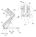
먼저 본 발명에 따른 특수 설치관 다각도 추진장치의 일실시예는 도 1 및 도 2에 나타낸 바와 같이, 추진관세트부(100)와, 추진로드부(200)를 포함하여 이루어진다.First, an embodiment of the special installation tube multi-angle propulsion device according to the present invention includes a propulsion pipe set
상기 추진관세트부(100)는 하수관이나 인공 등의 기설 본관(PP)에 대응하여 지반을 굴착가능하게 적용되는 관로 형성용 공구로서의 기능을 수행한다.The propulsion pipe set
상기 추진관세트부(100)는 도 2에 나타낸 바와 같이, 상기 추진로드부(200)의 전방에 장착가능한 구조를 이루며, 지반에 직접적으로 접촉하여 지중에 새로운 경로의 관로를 형성가능하게 구비된다.As shown in FIG. 2, the propulsion pipe set
상기 추진관세트부(100)는 두 가지 기능적 유형으로 구분 적용할 수 있는 구조로서, 지중에 관로를 삭진하기 위한 기능적 유형으로 적용하여 구성하는 것도 가능하고, 기설 본관(PP)을 절단 및 회수하기 위한 기능적 유형으로 적용하여 구성하는 것도 가능하다.The propulsion pipe set
상기 추진관세트부(100)의 제1실시예는 도 3에 나타낸 바와 같이, 지반에 직접적으로 접하여 회전운동 및 직선운동을 복합적으로 작용시킴에 따라 지중에 관로를 삭진시킬 수 있게 구성한다. 즉 상기 추진관세트부(100)는 전방에서 지반을 굴착하는 굴착수단(110)과, 굴착 경로에 관로를 형성하는 외부강관(120)을 구비토록 구성한다.As shown in FIG. 3, the first embodiment of the propulsion pipe set
상기 굴착수단(110)은 최전방에 위치하며 상기 추진로드부(200)로부터 회전운동가능하되 지면과의 접촉으로 굴착진행할 수 있는 굴착헤드(111)를 구비한다.The excavation means 110 is located at the forefront and is provided with an
상기 굴착헤드(111)는 지반과의 회전접촉으로 지반이 굴착될 수 있게 복수의 분쇄날(112)을 구비하며, 지반의 굴착 토사나 자갈은 복수의 분쇄날(112) 사이 공간을 통해 후방으로 이동될 수 있게 형성한다.The
상기 굴착수단(110)에는 상기 굴착헤드(111)로부터 굴착이동된 토사나 자갈을 후방으로 배출 이송시키는 굴착스크류(113)를 구비한다.The excavation means 110 is provided with an
상기 굴착스크류(113)는 상기 외부강관(120) 내 위치하고 상기 굴착헤드(111)의 후방에 굴착 길이방향으로 연속해서 축 연결하여 결합 설치된다.The
상기 굴착스크류(113)는 축을 기준으로 외측에 나선형의 날개가 반복 형성된 구조를 이룬다.The
상기 외부강관(120)은 상기 굴착수단(110)으로부터 굴착된 경로를 따라 직선방향으로 추진되어 새로운 설치본관(NP)의 외벽을 이루는 관로를 형성한다. 즉 상기 외부강관(120)은 상기 굴착수단(110)으로부터 굴착된 공간을 따라 추진되어 굴진 경로 상에 관로를 형성토록 매설된다.The
상기 외부강관(120)은 지중에 매설할 설치본관(NP)의 길이에 맞춰 복수 개를 반복적으로 투입 연결토록 구성한다.The
또한 상기 추진관세트부(100)의 제2실시예는 도 4에 나타낸 바와 같이, 기설 본관(PP)에 대응하여 중심부(5)를 절단함과 동시에 중심부(5)를 회수할 수 있게 구성한다. 즉 상기 추진관세트부(100)는 전방에서 기설 본관(PP)의 중심부(5)를 절단하는 중심커터수단(130)과, 관로 내 중심부(5)를 회수하는 중심회수수단(140)을 구성한다.In addition, according to the second embodiment of the propulsion pipe set
상기 중심커터수단(130)은 전방에 기설 본관의 벽면을 향해 접하여 중심부를 절단할 수 있는 구조로서, 전방에는 복수 개의 다이아몬드 커터를 구비토록 구성한다.The center cutter means 130 is a structure capable of cutting the central portion in contact with the wall surface of the existing main building in the front, it is configured to have a plurality of diamond cutter in the front.
상기 중심커터수단(130)은 상기 추진로드부(200)로부터 상기 기설 본관(PP)에 대응하여 위치한 상기 중심커터수단(130)에 회전력이 전달될 수 있게 복수 개의 드릴로드(135)가 연결 결합된 구조를 이룬다.The center cutter means 130 is coupled to the plurality of
상기 중심회수수단(140)은 상기 중심커터수단(130)의 내측에서 전방을 향해 돌출가능하게 구비되고, 상기 중심커터수단(130)으로부터 절단된 중심부(5)를 회수토록 회수비트(141)를 구비한다.The center recovery means 140 is provided so as to protrude forward from the inside of the center cutter means 130, the
상기 추진로드부(200)는 지상에 위치하고 상기 추진관세트부(100)가 지반의 추진방향을 향해 굴진될 수 있게 회전력 및 추진력을 생성시키는 기능을 수행한다.The
상기 추진로드부(200)는 도 1 및 도 2에 나타낸 바와 같이, 베이스프레임(210) 및 추진프레임(220)과, 추진유닛(230)을 구비토록 구성한다.As shown in FIGS. 1 and 2, the pushing
상기 베이스프레임(210)은 지면에 고정 설치되되 상하로 적층 형성된 구조를 이루며 일단이 힌지축(215) 결합하여 회전가능한 구조를 이루는 구성으로서, 하부에서 지면에 고정 설치될 수 있게 구비되는 고정프레임(211)과, 상기 고정프레임(211)의 상부에 위치하되 상기 고정프레임(211)의 일단에 힌지축(215) 결합하는 가변프레임(213)을 구성한다.The
상기 가변프레임(213)에는 상부에 가이드레일(214)이 형성된다. 즉 상기 가이드레일(214)은 상기 가변프레임(213) 상에 전후로 연장 형성되고, 상기 추진프레임(220)의 폭 만큼 좌우 일정한 거리를 두고 한 쌍을 구비토록 형성한다.A
상기 베이스프레임(210)에는 기설 본관(PP)을 향하는 상기 추진관세트부(100)의 추진방향을 설정토록 상기 추진프레임(220)의 각도를 조정하는 각도조정수단(240)을 구성한다. 즉 상기 가변프레임(213)은 상기 각도조정수단(240)에 의해 회전가능하여 상기 추진프레임(220)의 각도를 다양하게 조정하는 것이 가능하도록 구성한다.The
상기 각도조정수단(240)은 로드의 신장운동을 통해 상기 가변프레임(213)의 각도를 조정함을 기초로 한다.The angle adjusting means 240 is based on adjusting the angle of the
상기 각도조정수단(240)에서는 상기 고정프레임(211)을 기준으로 상기 가변프레임(213)을 0~90°의 범위 내에서 각도조정가능하다. 즉 상기 가변프레임(213)은 상기 고정프레임(211)과의 평행상태인 0°에서 상기 고정프레임(211)과 직각상태인 90°의 각도범위까지 상기 각도조정수단(240)에 의하여 조정가능하게 구성한다.In the angle adjusting means 240, the
상기 각도조정수단(240)은 상기 추진유닛(230)에 따른 추진작업을 위하여 복수 개의 실린더를 구비한 구조로 구성하는 것도 가능하고, 독립된 실린더 구조로부터 로드를 잠금가능한 구조로 구성하는 것도 가능하다.The angle adjusting means 240 may be of a structure having a plurality of cylinders for the propulsion operation according to the
상기 각도조정수단(240)의 제1실시예는 도 5에 나타낸 바와 같이, 복수 개의 실린더를 구비한 구조로서, 가변구동실린더(241) 및 보조구동실린더(243)를 구비토록 구성한다.As shown in FIG. 5, the first embodiment of the angle adjusting means 240 has a structure having a plurality of cylinders, and includes a
상기 가변구동실린더(241)는 상기 고정프레임(211) 및 상기 가변프레임(213)에 연결 결합하고, 상기 추진프레임(220)의 추진구동가능한 각도 조정을 위하여 상기 가변프레임(213)을 회전시킬 수 있게 신장운동한다.The
상기 보조구동실린더(243)는 상기 가변구동실린더(241)로부터 각도 조정된 가변프레임(213)에 재차 힘을 가해 위치 고정토록 신장운동한다. 즉 상기 추진프레임(220) 및 추진유닛(230)의 추진구동에 의하여 각도설정된 가변프레임(213)이 흔들리거나 각도변형됨을 방지할 수 있게 신장운동한다.The
또한 상기 각도조정수단(240)의 제2실시예는 도 6에 나타낸 바와 같이, 독립된 실린더 구조로부터 로드를 잠금가능한 구조로서, 가변구동실린더(241) 및 로크수단(245)을 구비토록 구성한다.In addition, the second embodiment of the angle adjusting means 240 is a structure capable of locking the rod from the independent cylinder structure, as shown in Figure 6, it is configured to include a
상기 가변구동실린더(241)는 상기 고정프레임(211) 및 상기 가변프레임(213)에 연결 결합하고, 상기 추진프레임(220)의 추진구동가능한 각도 조정을 위하여 상기 가변프레임(213)을 회전시킬 수 있게 신장운동한다.The
상기 로크수단(245)은 상기 가변구동실린더(241) 상에 설치되고 상기 가변구동실린더(241)의 로드를 잠금 고정할 수 있게 구성한다.The locking means 245 is installed on the
상기 로크수단(245)은 상기 추진프레임(220)의 각도 조정된 상기 가변구동실린더(241)의 신장상태를 잠금 고정하여 가변구동실린더(241)의 움직임을 방지한다.The locking means 245 locks and extends the extended state of the
상기 로크수단(245)은 핀 형 또는 유압형으로 구성하는 것이 가능하다.The locking means 245 can be configured as a pin type or a hydraulic type.
상기 로크수단(245)은 도 6에 나타낸 바와 같이, 핀 형 로크수단(245)의 구조로서, 상기 가변구동실린더(241)의 로드 상에 길이방향으로 간격을 두고 형성된 복수 개의 핀공(245a)을 구비하고, 상기 핀공(245a)에 대응하여 결속가능하게 구비되는 로크핀부재(245b)를 구비토록 구성한다.As shown in FIG. 6, the locking means 245 has a structure of a pin-type locking means 245, and includes a plurality of
상기 로크핀부재(245b)와 상기 핀공(245a)은 상호 나사 결합가능한 구조를 이루어 결속력을 보다 향상시킬 수 있게 구성하는 것이 바람직하다.The
또한 상기 로크수단(245)은 도 7에 나타낸 바와 같이, 유압형 로크수단(245)의 구조로서, 상기 가변구동실린더(241)의 로드에 직접적인 압력을 가할 수 있게 유압의 공급 여부에 따라 구동토록 구성한다.In addition, the locking means 245 is a structure of the hydraulic locking means 245, as shown in Figure 7, so as to drive depending on whether or not the hydraulic supply to apply a direct pressure to the rod of the
상기 로크수단(245)은 상기 가변구동실린더(241)의 로드를 수용토록 수직관통된 하우징(246)과, 상기 하우징(246) 내 설치되어 유체의 공급 여부에 따라 상하로 이동하여 가압가능한 피스톤(247)과, 상기 피스톤(247)으로부터 가해지는 압력에 의해 상기 가변구동실린더(241)의 로드를 압착 고정하는 잠금부재(248)를 구성한다.The locking means 245 includes a
상기 하우징(246)에는 하향할수록 좁은 공간을 갖는 경사지지면(249)을 형성하고, 상기 잠금부재(248)는 상기 경사지지면(249)에 대응하여 면 접촉상태로 상하 미끄럼 이동가능하게 설치된다.An
상기 잠금부재(248)는 상하 직경이 다른 원형의 단면형상으로 이루어진다.The locking
상기 잠금부재(248)에는 서로 간격을 두고 이격된 공간을 갖는 절개구(C)를 형성한다.The locking
상기 잠금부재(248)는 내측에 상기 가변구동실린더(241)의 로드를 수용하면서 상기 피스톤(247)을 향한 유체의 공급 여부에 따라 가변하여 로드에 압력을 가할 수 있게 면 접촉하는 가압공(H)을 형성한다. 즉 외부로부터 유압공급 여부에 따라 상기 피스톤(247)이 상기 잠금부재(248)를 접촉 이동시키며, 상기 잠금부재(248)의 경우 상기 하우징(246)의 경사지지면(249)을 따라 미끄럼 이동하여 상기 절개구(C)의 이격 거리를 좁힐 수 있으므로 상기 가압공(H)이 상기 가변구동실린더(241)의 로드에 지속적으로 압착하여 로드를 잠금상태로 고정하는 것이 가능하다.The locking
상기와 같이 로크수단(245)을 구성하게 되면, 추진작업시 각도설정상태를 유지하기 위한 로드의 밀림현상을 효과적으로 방지하는 것이 가능하다.When the locking means 245 is configured as described above, it is possible to effectively prevent the sliding phenomenon of the rod for maintaining the angle setting state during the propulsion operation.
상기 추진프레임(220)은 상기 베이스프레임(210) 중 상기 가변프레임(213)의 가이드레일(214) 상에 연결 결합하여 설치된다.The
상기 추진프레임(220)은 상기 추진관세트부(100)의 추진방향 즉 전방을 향해 추진시킬 수 있게 상기 가변프레임(213)의 가이드레일(214)을 따라 전후로 왕복이동가능하게 설치된다.The
상기 추진유닛(230)은 상기 추진프레임(220) 상에 설치되고 상기 추진관세트부(100)를 장착 지지할 수 있게 구성한다.The
상기 추진유닛(230)은 도 2에 나타낸 바와 같이, 상기 추진관세트부(100)가 전방을 향해 추진될 수 있게 구동하는 구성으로서, 제1추진유닛(231) 및 제2추진유닛(233)을 구비토록 구성한다.As shown in FIG. 2, the
상기 제1추진유닛(231)은 상기 추진프레임(220)의 전방에 상기 추진관세트부(100)를 결합 고정하여 회전동력을 인가하는 기능을 수행한다.The
상기 제1추진유닛(231)은 상기 추진관세트부(100)의 일단을 연결 고정할 수 있게 구비되는 공구장착수단(231a)과, 상기 공구장착수단(231a)에 회전동력을 인가하는 구동모터(231b)를 구성한다.The
상기 공구장착수단은 상기 추진프레임(220)의 전방에 돌출 형성되고, 상기 구동모터(231b)로부터 전달되는 회전동력에 의해 회전가능하게 구비된다.The tool mounting means is protruded in front of the
예를 들면, 상기 공구장착수단(231a)에는 상기 추진관세트부(100) 중 지반 굴착작업을 위한 굴착스크류(113) 및 굴착헤드(111)로 이루어진 굴착수단(110)이 장착되고, 상기 굴착수단(110)에 지속적인 회전동력을 인가할 수 있게 구성한다. 나아가 상기 공구장착수단(231a)에는 상기 굴착수단(110) 외에도 상기 추진관세트부(100) 중 중심커터수단(130)이나 중심회수수단(140) 등의 구성들을 장작하여 회전구동시킬 수 있게 구성한다.For example, the tool mounting means 231a is equipped with an excavation means 110 consisting of an
상기 구동모터(231b)는 상기 추진프레임(220) 상에 설치되고, 상기 공구장착수단(231a)에 다양한 형태의 벨트 등으로 동력전달가능하게 서로 연결된 구조를 이룬다.The
상기 제2추진유닛(233)은 상기 추진프레임(220)의 전방에 상기 추진관세트부(100)를 지지 고정하여 전방을 향한 추진동력을 인가할 수 있는 기능을 수행한다.The
상기 제2추진유닛(233)은 상기 추진관세트부(100)를 장착하는 관장착수단(233a)과, 상기 관장착수단(233a)에 추진동력을 인가할 수 있게 구동하는 구동실린더(233b)를 구성한다.The
상기 관장착수단(233a)은 상기 제1추진유닛(231) 중 공구장착수단(231a)의 외측에 간격을 두고 위치하고, 상기 추진관세트부(100)를 장착시킬 수 있게 구성한다.The pipe mounting means 233a is positioned at an outer side of the tool mounting means 231a of the
상기 관장착수단(233a)은 관 형태의 상기 추진관세트부(100)를 추진가능하게 고정하는 구성으로서, 상기 추진관세트부(100) 중 설치본관(NP)의 외벽을 이루는 외부강관(120)의 후방을 끼움 접촉상태로 고정할 수 있게 구성한다.The pipe mounting means 233a is configured to propellably fix the propulsion pipe set
상기 관장착수단(233a)은 상기 추진관세트부(100)와 대응하여 상기 추진관세트부(100)를 끼움 상태로 지지할 수 있게 지지단턱(234)을 형성한다.The pipe mounting means 233a forms a
상기 구동실린더(233b)는 상기 추진프레임(220) 상에 좌우 간격을 두고 설치되고, 상기 구동실린더(233b) 중 로드의 일단이 상기 베이스프레임(210)에 연결 결합하여 상기 구동실린더(233b)의 신장운동에 따른 상기 추진프레임(220)의 전후 직선왕복운동을 도모할 수 있게 구동한다. 즉 상기 제2추진유닛(233)에서는 상기 구동실린더(233b)의 직선운동에 따른 무회전 추진구조로서, 상기 외부강관(120)의 손상을 최소화하면서 토사층 등의 지중에 보다 효율적으로 시공하는 것이 가능하다.The driving
다음으로 상기와 같이 구성되는 특수 설치관 다각도 추진장치를 이용한 특수 설치관 다각도 추진공법을 설명한다.Next, a special installation pipe multi-angle propulsion method using a special installation pipe multi-angle propulsion device configured as described above.
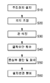
먼저 본 발명에 따른 특수 설치관 다각도 추진공법의 일실시예는 도 8 및 도 9에 나타낸 바와 같이, 추진장치 설치단계(S10)와, 각도 조정단계(S20)와, 관 삭진단계(S30)와, 굴착수단(110) 회수단계(S40)와, 중심부 절단 및 회수 단계(S50)와, 설치본관(NP) 형성단계(S60)를 포함하여 이루어진다.First, an embodiment of the special installation tube multi-angle propulsion method according to the present invention, as shown in Figure 8 and 9, the propulsion device installation step (S10), the angle adjustment step (S20), pipe cutting step (S30) and , Excavation means (110) recovery step (S40), the central cutting and recovery step (S50), and the installation main pipe (NP) forming step (S60) is made.
상기 추진장치 설치단계(S10)에서는 작업위치에 특수 설치관 다각도 추진장치(A)를 위치한 후 해당 위치의 지면에 부동상태로 고정 설치한다.In the propulsion device installation step (S10), after the special installation pipe multi-angle propulsion device (A) is placed in the working position and fixed to the ground of the corresponding position in a floating state.
상기 특수 설치관 다각도 추진장치(A)는 베이스프레임(210) 및 추진프레임(220), 추진유닛(230), 각도조정수단(240)으로 구성된 추진로드부(200)와, 관로 형성을 위한 추진관세트부(100)를 포함하되, 상기 추진로드부(200)의 베이스프레임(210)을 지면에 설치 고정하고, 상기 추진로드부(200)의 추진유닛(230) 상에 상기 추진관세트부(100)를 작업가능하게 장착한다.The special installation pipe multi-angle propulsion device (A) is the
상기에서 추진관세트부(100)로는 굴착스크류(113) 및 굴착헤드(111)로 구성된 굴착수단(110)과, 설치본관(NP)의 최외측 벽면을 이루는 외부강관(120)을 적용토록 설치한다.The propulsion pipe set
상기 각도 조정단계(S20)에서는 기설 본관에 대응하여 새로운 설치본관(NP)을 시공할 수 있게 상기 특수 설치관 다각도 추진장치(A)의 추진방향을 설정토록 각도 조정한다.In the angle adjustment step (S20) to adjust the propulsion direction of the special installation pipe multi-angle propulsion device (A) to set the new installation main pipe (NP) corresponding to the existing main building.
상기에서 특수 설치관 다각도 추진장치(A)를 각도 조정함에는 상기 각도조정수단(240)을 구동시켜 상기 베이스프레임(210)을 회전시키므로, 상기 추진프레임(220)이 설정 경사각도를 설정토록 구동한다.In adjusting the angle of the special installation tube multi-angle propulsion device (A) in the drive the angle adjusting means 240 to rotate the
상기 관 삭진단계(S30)에서는 상기 특수 설치관 다각도 추진장치(A)을 전방 지중을 향해 추진구동하여 기설 본관(PP)을 향한 새로운 굴착 경로를 형성함과 동시에 설치본관(NP) 중 외부강관(120)을 설치토록 관 삭진한다.In the pipe cutting step (S30), the special installation pipe multi-angle propulsion unit (A) is propelled toward the ground underground to form a new excavation path toward the existing main pipe (PP) and at the same time the external steel pipe (NP)
상기 관 삭진단계(S30)에서는 상기 굴착수단(110) 중 굴착헤드(111) 및 굴착스크류(113)를 회전구동시킴에 따라 지반을 굴착하면서 외부로 토사 및 자갈을 배출시키고, 상기 외부강관(120)을 무회전 직선이동시켜 지중에 외부강관(120)을 매립 설치한다.In the pipe cutting step (S30) while driving the
상기 굴착수단(110) 회수단계(S40)에서는 상기 외부강관(120) 내 잔토를 연속적으로 처리하면서 상기 특수 설치관 다각도 추진장치(A)의 굴착수단(110)을 순차적으로 회수한다.In the excavation means 110 recovery step (S40) while recovering the residual soil in the
상기 중심부 절단 및 회수 단계(S50)에서는 상기 외부강관(120)이 설치된 설치본관(NP)의 설치경로에 대응하여 기설 본관(PP)의 벽면 중심부(5)를 절단한 후 회수토록 진행한다.In the central cutting and recovery step (S50) in response to the installation path of the installation main pipe (NP) in which the
상기에서 중심부(5)를 절단함에는 상기 굴착수단(110)이 분리된 상기 특수 설치관 다각도 추진장치(A)의 추진로드부(200)에 중심커터수단(130)을 장착하고, 상기 중심커터수단(130)을 상기 외부강관(120) 내 진입시킨 후 회전구동시켜 기설 본관(PP)의 벽면을 절단한다.In the cutting of the
상기 중심커터수단(130)에는 전방에 돌출가능하게 구비된 회수비트(141)로부터 중심부(5)를 취득하고, 상기 중심커터수단(130)을 외부로 철수시킴과 동시에 절단된 중심부(5)를 자연히 회수한다.The center cutter means 130 acquires the
상기 설치본관(NP) 형성단계(S60)에서는 상기 외부강관(120)이 설치된 관로경로를 설치본관(NP)으로 제작형성한다.In the installation main pipe (NP) forming step (S60), the pipe path in which the
상기 설치본관(NP) 형성단계(S60)에서는 상기 외부강관(120)의 내측에 내관(10)을 설치한다.In the installation main pipe (NP) forming step (S60), the
상기에서 내관(10)은 도 10에 나타낸 바와 같이, 특수지관(10a)과 염화비닐관(10b)이 서로 연결된 조립체로서, 상기 특수지관(10a)이 기설 본관(PP)의 관통된 중심부(5)에 결속되고, 상기 특수지관(10a)의 일단에 염화비닐관(10b)이 반복적으로 연결 결합하여 상기 외부강관(120)과 대응되는 길이의 내관(10)을 형성한다.As shown in FIG. 10, the
상기 기설 본관(PP) 내 결속된 상기 특수지관(10a)의 연결지점에는 수밀을 위한 물막이 접착제(11)가 도포된다.At the connection point of the special branch pipe (10a) bound in the existing main pipe (PP), a
상기 외부강관(120)과 상기 내관(10)의 사이에는 중간몰탈(13)을 채워 양생시킴에 따라 완성된 설치본관(NP)을 형성한다.Between the
즉 상기와 같이 구성되는 본 발명에 따른 특수 설치관 다각도 추진장치 및 그 추진공법에 의하면, 지상에서 지중을 향한 설치본관의 신설작업을 일률적으로 진행할 수 있게 추진하므로 지반 개착작업 또는 전진기지의 굴착작업 등의 준비공정이 불필요하여 작업이 매우 간편함과 동시에 시공공기를 대폭 단축하고, 기설 본관을 향해 설치본관의 추진방향이 다양한 각도로 조정될 수 있게 구성하므로 설치본관의 신설작업이 매우 용이함은 물론 작업유형을 다양하게 개선하는 것이 가능하다.That is, according to the special installation pipe multi-angle propulsion device and the propulsion method according to the present invention configured as described above, so that the new construction work of the installation main building from the ground to the ground can be carried out uniformly so that ground attachment work or excavation work of the forward base It is very easy to work because there is no preparation process, etc., and the construction air is greatly reduced, and the propulsion direction of the installation main body can be adjusted at various angles toward the existing main building. It is possible to improve variously.
이상의 설명은 본 발명의 기술사상을 예시적으로 설명한 것에 불과한 것으로서, 본 발명이 속하는 기술 분야에서 통상의 지식을 가진 자라면 본 발명의 본질적인 특성에서 벗어나지 않는 범위에서 다양한 수정 및 변형이 가능할 것이다. 따라서, 본 발명에 개시된 도면들은 본 발명의 기술 사상을 한정하기 위한 것이 아니라 설명하기 위한 것이고, 이러한 도면들에 의하여 본 발명의 기술 사상의 범위가 한정되는 것은 아니다. 본 발명의 보호 범위는 아래의 청구범위에 의하여 해석되어야 하며, 그와 동등한 범위 내에 있는 모든 기술 사상은 본 발명의 권리범위에 포함되는 것으로 해석되어야 할 것이다.The above description is merely illustrative of the technical spirit of the present invention, and those skilled in the art to which the present invention pertains may make various modifications and changes without departing from the essential characteristics of the present invention. Therefore, the drawings disclosed in the present invention are not intended to limit the technical spirit of the present invention but to explain, and the scope of the technical spirit of the present invention is not limited by these drawings. The scope of protection of the present invention should be interpreted by the following claims, and all technical ideas within the scope equivalent thereto should be construed as being included in the scope of the present invention.
100 : 추진관세트부
110 : 굴착수단
111 : 굴착헤드
113 : 굴착스크류
120 : 외부강관
130 : 중심커터수단
135 : 드릴로드
140 : 중심회수수단
200 : 추진로드부
210 : 베이스프레임
211 : 고정프레임
213 : 가변프레임
214 : 가이드레일
215 : 힌지축
220 : 추진프레임
230 : 추진유닛
231 : 제1추진유닛
231a : 공구장착수단
231b : 구동모터
233 : 제2추진유닛
233a : 관장착수단
233b : 구동실린더
240 : 각도조정수단
241 : 가변구동실린더
243 : 보조구동실린더
245 : 로크수단100: propulsion tube set 110: excavation means 111: excavation head
113: excavation screw 120: outer steel pipe 130: center cutter means
135: drill rod 140: center recovery means 200: pushing rod
210: base frame 211: fixed frame 213: variable frame
214: guide rail 215: hinge shaft 220: propulsion frame
230: propulsion unit 231:
231b: drive motor 233:
233b: drive cylinder 240: angle adjustment means 241: variable drive cylinder
243: auxiliary driving cylinder 245: locking means
Claims (10)
지면에 고정 설치되고 상하로 적층 형성되되 일단이 힌지축 결합하여 회전가능한 구조를 이루는 베이스프레임과, 상기 베이스프레임 상에 전후로 왕복이동가능하게 설치되는 추진프레임과, 상기 추진프레임 상에 설치되고 상기 추진관세트부를 장착 지지하되 상기 추진관세트부가 전방을 향해 추진될 수 있게 구비되는 추진유닛으로 구성된 추진로드부;를 포함하고,
상기 추진로드부에는 상기 베이스프레임 상에 설치되고 상기 추진관세트부의 기설 본관을 향하는 추진방향을 설정토록 상기 추진프레임의 각도를 조정하는 각도조정수단을 포함하여 이루어지는 특수 설치관 다각도 추진장치.
A propulsion pipe set part capable of excavating the ground corresponding to the existing main building, and being capable of forming a new path in the ground;
A base frame fixed to the ground and stacked up and down and having one end coupled to a hinge shaft to form a rotatable structure, a propulsion frame installed on the base frame so as to be reciprocated back and forth, and installed on the propulsion frame And a propulsion rod part configured to support and support the tube set part, wherein the propulsion unit comprises a propulsion unit provided to be pushed forward.
The propulsion rod portion is installed on the base frame and the special installation tube multi-angle propulsion device comprising an angle adjusting means for adjusting the angle of the propulsion frame to set the propulsion direction toward the existing main pipe of the propulsion pipe set.
상기 추진관세트부는, 전방에 지면을 굴착가능하게 접하는 굴착헤드를 구비하며 상기 굴착헤드의 후방에 굴착 길이방향으로 연속 결합하여 굴착 토사 또는 자갈을 배출시키기 위한 굴착스크류를 구비하는 굴착수단과, 상기 굴착수단으로부터 굴착된 경로를 따라 추진되어 관로를 형성하는 외부강관을 포함하여 지중에 관로를 삭진할 수 있게 이루어지는 것을 특징으로 하는 특수 설치관 다각도 추진장치.
The method according to claim 1,
The propulsion pipe set part has an excavation head for contacting the ground in front of the excavation, and the excavation means having a drilling screw for discharging the excavated soil or gravel by continuously coupled in the excavation longitudinal direction to the rear of the excavation head, and the Special installation pipe multi-angle propulsion device, characterized in that made to be able to cut the pipeline in the ground, including the external steel pipe to be pushed along the excavated path from the excavating means to form a pipeline.
상기 추진관세트부는, 전방에 기설 본관의 벽면을 향해 접하여 중심부를 절단가능하게 구비되는 중심커터수단과, 상기 중심커터수단의 내측에서 전방을 향해 돌출가능하며 상기 중심커터수단으로부터 절단된 중심부를 회수하는 중심회수수단을 포함하여 기설 본관을 절단 및 회수할 수 있게 이루어지는 것을 특징으로 하는 특수 설치관 다각도 추진장치.
The method according to claim 2,
The propulsion pipe set part, the center cutter means provided in front of the wall of the existing main building so as to cut the center, and the center cutter means protrudes forward from the inside of the center cutter means and recover the center portion cut from the center cutter means Special installation pipe multi-angle propulsion device, characterized in that made to be able to cut and recover the existing main building, including a central recovery means.
상기 추진로드부의 베이스프레임은, 하부에서 지면에 고정 설치될 수 있게 구비되는 고정프레임과, 상기 고정프레임의 상부에 위치하되 상기 고정프레임의 일단에 힌지축 결합하고 상기 각도조정수단에 의해 회전가능하게 구비되는 가변프레임을 포함하여 이루어지는 특수 설치관 다각도 추진장치.
The method according to claim 1,
The base frame of the propulsion rod portion, a fixed frame provided to be fixed to the ground from the bottom, positioned on the upper portion of the fixed frame but hinged to one end of the fixed frame and rotatably by the angle adjusting means Special installation tube multi-angle propulsion device comprising a variable frame provided.
상기 각도조정수단은, 상기 고정프레임 및 상기 가변프레임에 연결 결합하고 상기 추진프레임의 각도 조정을 위하여 상기 가변프레임을 회전시킬 수 있게 신장운동하는 가변구동실린더와, 상기 가변구동실린더로부터 각도 조정된 가변프레임을 위치고정토록 신장운동하는 보조구동실린더를 포함하여 이루어지는 특수 설치관 다각도 추진장치.
The method according to claim 4,
The angle adjusting means includes a variable drive cylinder coupled to the fixed frame and the variable frame and extended to rotate the variable frame for adjusting the angle of the propulsion frame, and an angle adjusted variable from the variable drive cylinder. Special installation tube multi-angle propulsion device including auxiliary drive cylinder to extend the frame to fix the position.
상기 각도조정수단은, 상기 고정프레임 및 상기 가변프레임에 연결 결합하고 상기 추진프레임의 각도 조정을 위하여 상기 가변프레임을 회전시킬 수 있게 신장운동하는 가변구동실린더와, 상기 가변구동실린더 상에 설치되고 상기 추진프레임의 각도 조정을 신장상태를 유지할 수 있게 상기 가변구동실린더의 로드를 잠금 고정하는 로크수단을 포함하여 이루어지는 특수 설치관 다각도 추진장치.
The method according to claim 4,
The angle adjusting means is connected to the fixed frame and the variable frame and the variable drive cylinder for extending the movement to rotate the variable frame for adjusting the angle of the propulsion frame, and installed on the variable drive cylinder and the Special installation pipe multi-angle propulsion device comprising a lock means for locking and locking the rod of the variable drive cylinder to maintain the extended state of the propulsion frame.
상기 추진로드부의 추진유닛은, 상기 추진프레임의 전방에 상기 추진관세트부를 결합 고정하여 회전동력을 인가하는 제1추진유닛과, 상기 추진프레임의 전방에 상기 추진관세트부를 지지 고정하여 전방을 향한 추진동력을 인가하는 제2추진유닛을 포함하여 이루어지는 특수 설치관 다각도 추진장치.
The method according to claim 1,
The propulsion unit of the propulsion rod part includes: a first propulsion unit coupled to fix the propulsion pipe set part to the front of the propulsion frame to apply rotational power; Special installation pipe multi-angle propulsion device comprising a second propulsion unit for applying the propulsion power.
상기 제1추진유닛은, 상기 추진프레임의 전방에 돌출 형성되되 회전가능하게 구비되고 상기 추진관세트부의 일단을 연결 고정하는 공구장착수단과, 상기 추진프레임 상에 설치되고 상기 공구장착수단에 회전동력을 인가하는 구동모터를 포함하여 이루어지는 특수 설치관 다각도 추진장치.
The method according to claim 7,
The first propulsion unit includes a tool mounting means which protrudes in front of the propulsion frame and is rotatably provided and connects and fixes one end of the propulsion pipe set portion, and is installed on the propulsion frame and rotates on the tool mounting means. Special installation pipe multi-angle propulsion device comprising a drive motor for applying a.
상기 제2추진유닛은, 상기 제1추진유닛의 외측에 간격을 두고 위치하고 상기 추진관세트부에 끼움 접촉상태로 고정하는 관장착수단과, 상기 추진프레임 상에 설치되되 일단이 상기 베이스프레임에 연결 결합하고 상기 추진프레임을 전후로 직선왕복운동시키는 구동실린더를 포함하여 이루어지는 특수 설치관 다각도 추진장치.
The method according to claim 7,
The second propulsion unit is disposed on the outside of the first propulsion unit spaced apart from the tube mounting means for fixing in the state of fitting in the propulsion pipe set portion, and installed on the propulsion frame, one end is connected to the base frame Special installation pipe multi-angle propulsion device comprising a drive cylinder coupled and reciprocating linearly forward and backward the propulsion frame.
기설 본관에 대응하여 새로운 설치본관을 시공할 수 있게 상기 특수 설치관 다각도 추진장치의 추진방향을 설정토록 각도 조정하는 단계와;
상기 특수 설치관 다각도 추진장치을 전방 지중을 향해 추진구동하여 기설 본관을 향한 새로운 굴착 경로를 형성함과 동시에 설치본관 중 외부강관을 설치토록 관 삭진하는 단계와;
상기 외부강관 내 잔토를 처리하면서 상기 특수 설치관 다각도 추진장치의 굴착수단을 회수하는 단계와;
상기 외부강관 내 중심커터수단을 진입시킨 후 기설 본관의 벽면 중심부를 절단하고, 상기 중심커터수단을 철수함과 동시에 절단된 중심부를 회수하는 단계와;
상기 외부강관의 내측에 내관을 설치하고, 상기 외부강관과 상기 내관의 사이에 중간몰탈을 채워 설치본관을 형성하는 단계;를 포함하여 이루어지는 특수 설치관 다각도 추진공법.
Fixing the special installation pipe multi-angle propulsion device to a working position;
Adjusting the propulsion direction of the special installation tube multi-angle propulsion device so as to construct a new installation main building corresponding to the existing main building;
Driving the special installation pipe multi-angle propulsion device toward the ground to form a new excavation path toward the existing main building and simultaneously cutting the pipe to install an external steel pipe among the installation main pipes;
Recovering the excavation means of the special installation pipe multi-angle propulsion device while treating the remaining soil in the external steel pipe;
Cutting the center of the wall surface of the existing main pipe after entering the center cutter means in the outer steel pipe, withdrawing the center cutter means and recovering the cut center portion;
Installing an inner tube on the inner side of the outer steel pipe, filling the intermediate mortar between the outer steel pipe and the inner pipe to form an installation main pipe; special installation pipe multi-angle propelling method comprising a.
Priority Applications (1)
| Application Number | Priority Date | Filing Date | Title |
|---|---|---|---|
| KR1020180096886A KR102115147B1 (en) | 2018-08-20 | 2018-08-20 | Multi-Angle Propulsion Apparatus and Method for Special Pipe |
Applications Claiming Priority (1)
| Application Number | Priority Date | Filing Date | Title |
|---|---|---|---|
| KR1020180096886A KR102115147B1 (en) | 2018-08-20 | 2018-08-20 | Multi-Angle Propulsion Apparatus and Method for Special Pipe |
Publications (2)
| Publication Number | Publication Date |
|---|---|
| KR20200021299A true KR20200021299A (en) | 2020-02-28 |
| KR102115147B1 KR102115147B1 (en) | 2020-05-26 |
Family
ID=69638451
Family Applications (1)
| Application Number | Title | Priority Date | Filing Date |
|---|---|---|---|
| KR1020180096886A KR102115147B1 (en) | 2018-08-20 | 2018-08-20 | Multi-Angle Propulsion Apparatus and Method for Special Pipe |
Country Status (1)
| Country | Link |
|---|---|
| KR (1) | KR102115147B1 (en) |
Families Citing this family (1)
| Publication number | Priority date | Publication date | Assignee | Title |
|---|---|---|---|---|
| KR102470277B1 (en) | 2021-12-06 | 2022-11-23 | 윤택규 | Propulsion system for Saving Space and propulsion method using thereof |
Citations (7)
| Publication number | Priority date | Publication date | Assignee | Title |
|---|---|---|---|---|
| JPH0650465A (en) * | 1991-09-19 | 1994-02-22 | Pub Works Res Inst Ministry Of Constr | Process of attaching branch pipe to underground main pipe |
| JPH0742486A (en) * | 1993-07-28 | 1995-02-10 | Kubota Corp | Thrusting device |
| KR100231188B1 (en) | 1996-06-07 | 1999-11-15 | 위성경 | Propulsion method and apparatus for underground conduits |
| JP3124065B2 (en) * | 1991-05-18 | 2001-01-15 | 知勇 重盛 | A method of attaching branch pipes to existing buried objects |
| KR100814711B1 (en) | 2006-08-11 | 2008-03-18 | 건양씨엔이 (주) | An Portable Apparatus and Methods of the Propulsion for the very small diameter pipes |
| JP4109497B2 (en) * | 2002-05-30 | 2008-07-02 | 東京瓦斯株式会社 | Pipe laying method |
| JP6102917B2 (en) * | 2012-04-09 | 2017-03-29 | 旭硝子株式会社 | Azeotropic or azeotrope-like composition and method for producing 2,3,3,3-tetrafluoropropene or chloromethane |
-
2018
- 2018-08-20 KR KR1020180096886A patent/KR102115147B1/en active IP Right Grant
Patent Citations (7)
| Publication number | Priority date | Publication date | Assignee | Title |
|---|---|---|---|---|
| JP3124065B2 (en) * | 1991-05-18 | 2001-01-15 | 知勇 重盛 | A method of attaching branch pipes to existing buried objects |
| JPH0650465A (en) * | 1991-09-19 | 1994-02-22 | Pub Works Res Inst Ministry Of Constr | Process of attaching branch pipe to underground main pipe |
| JPH0742486A (en) * | 1993-07-28 | 1995-02-10 | Kubota Corp | Thrusting device |
| KR100231188B1 (en) | 1996-06-07 | 1999-11-15 | 위성경 | Propulsion method and apparatus for underground conduits |
| JP4109497B2 (en) * | 2002-05-30 | 2008-07-02 | 東京瓦斯株式会社 | Pipe laying method |
| KR100814711B1 (en) | 2006-08-11 | 2008-03-18 | 건양씨엔이 (주) | An Portable Apparatus and Methods of the Propulsion for the very small diameter pipes |
| JP6102917B2 (en) * | 2012-04-09 | 2017-03-29 | 旭硝子株式会社 | Azeotropic or azeotrope-like composition and method for producing 2,3,3,3-tetrafluoropropene or chloromethane |
Also Published As
| Publication number | Publication date |
|---|---|
| KR102115147B1 (en) | 2020-05-26 |
Similar Documents
| Publication | Publication Date | Title |
|---|---|---|
| KR101944262B1 (en) | Simultaneous propulsion construction method using double pipe | |
| CN110529136A (en) | Municipal blow-off line pipe jacking construction method | |
| CN107916937A (en) | Drilling tool, drilling machine and drilling method | |
| KR20150001137A (en) | Horizontal well drilling device having oil pressure cylinder | |
| KR102105160B1 (en) | Piercing tool indentation method | |
| KR102115147B1 (en) | Multi-Angle Propulsion Apparatus and Method for Special Pipe | |
| KR101410853B1 (en) | Tunneling Apparatus for Pipeline Excavation | |
| KR101650913B1 (en) | Tilting type excavation apparatus for propulsion pipes | |
| KR101410851B1 (en) | Tunneling Apparatus for Pipeline Excavation | |
| KR101233977B1 (en) | Small size tunneling machine using hydraulic cylinder for moving, and tunneling method using the same | |
| JP6479892B2 (en) | Cutting crushing system, cutting crushing method, reconstruction promotion method | |
| KR100515684B1 (en) | Propulsion method of construction and the device for pipe piercing | |
| KR101237749B1 (en) | Propulsion unit head that is used in shield method | |
| KR100466940B1 (en) | A method for the trenchless horizontal tunnel using a pilot lod trench method and its apparatus | |
| JP2005180112A (en) | Ground improvement structure and ground improvement method | |
| JP2837394B2 (en) | Pipe propulsion machine | |
| KR20160071274A (en) | Tunnel boring apparatus to move back and forth | |
| KR200281084Y1 (en) | A tunnel boring machine | |
| KR20150008654A (en) | Ground excavator | |
| KR20100066944A (en) | Drill and drilling apparatus using the same | |
| CN208441777U (en) | A kind of underground pipe machine synchronous construction machine | |
| JP6438810B2 (en) | Pipe installation device | |
| JPH11247591A (en) | Connection method of underground structure using jacking device | |
| KR20030005651A (en) | Pipe laying apparatus | |
| JP6438811B2 (en) | Pipe installation device |
Legal Events
| Date | Code | Title | Description |
|---|---|---|---|
| A201 | Request for examination | ||
| E902 | Notification of reason for refusal | ||
| E701 | Decision to grant or registration of patent right | ||
| GRNT | Written decision to grant |