KR20200017474A - Beam based downlink control signaling - Google Patents
Beam based downlink control signaling Download PDFInfo
- Publication number
- KR20200017474A KR20200017474A KR1020207000887A KR20207000887A KR20200017474A KR 20200017474 A KR20200017474 A KR 20200017474A KR 1020207000887 A KR1020207000887 A KR 1020207000887A KR 20207000887 A KR20207000887 A KR 20207000887A KR 20200017474 A KR20200017474 A KR 20200017474A
- Authority
- KR
- South Korea
- Prior art keywords
- beams
- monitoring
- dmrs
- block
- control information
- Prior art date
Links
Images


Classifications
-
- H—ELECTRICITY
- H04—ELECTRIC COMMUNICATION TECHNIQUE
- H04W—WIRELESS COMMUNICATION NETWORKS
- H04W72/00—Local resource management
- H04W72/20—Control channels or signalling for resource management
- H04W72/23—Control channels or signalling for resource management in the downlink direction of a wireless link, i.e. towards a terminal
-
- H—ELECTRICITY
- H04—ELECTRIC COMMUNICATION TECHNIQUE
- H04L—TRANSMISSION OF DIGITAL INFORMATION, e.g. TELEGRAPHIC COMMUNICATION
- H04L5/00—Arrangements affording multiple use of the transmission path
- H04L5/003—Arrangements for allocating sub-channels of the transmission path
- H04L5/0053—Allocation of signaling, i.e. of overhead other than pilot signals
-
- H—ELECTRICITY
- H04—ELECTRIC COMMUNICATION TECHNIQUE
- H04L—TRANSMISSION OF DIGITAL INFORMATION, e.g. TELEGRAPHIC COMMUNICATION
- H04L1/00—Arrangements for detecting or preventing errors in the information received
- H04L1/12—Arrangements for detecting or preventing errors in the information received by using return channel
- H04L1/16—Arrangements for detecting or preventing errors in the information received by using return channel in which the return channel carries supervisory signals, e.g. repetition request signals
- H04L1/18—Automatic repetition systems, e.g. Van Duuren systems
- H04L1/1812—Hybrid protocols; Hybrid automatic repeat request [HARQ]
-
- H—ELECTRICITY
- H04—ELECTRIC COMMUNICATION TECHNIQUE
- H04L—TRANSMISSION OF DIGITAL INFORMATION, e.g. TELEGRAPHIC COMMUNICATION
- H04L5/00—Arrangements affording multiple use of the transmission path
- H04L5/003—Arrangements for allocating sub-channels of the transmission path
- H04L5/0078—Timing of allocation
-
- H—ELECTRICITY
- H04—ELECTRIC COMMUNICATION TECHNIQUE
- H04W—WIRELESS COMMUNICATION NETWORKS
- H04W56/00—Synchronisation arrangements
- H04W56/0005—Synchronisation arrangements synchronizing of arrival of multiple uplinks
Abstract
다운링크(DL) 제어, 무승인(GF) 송신, 또는 초기 액세스와 연관된 방법들, 시스템들, 및 디바이스들이 본원에 개시된다. 특히, 다른 것들 중에서도, 다중 빔 물리적 다운링크 제어 채널(PDCCH) 송신 메커니즘들, 무승인 송신 메커니즘들, 물리적 브로드캐스트 채널(PBCH)에 대한 복조 기준 신호(DMRS) 메커니즘들, 및 엔알-채널 상태 정보-기준 신호(NR-CSI-RS) 및 엔알-물리적 다운링크 공유 채널(PDSCH)(NR-PDSCH)에 대한 DMRS 시퀀스 설계가 본원에 개시된다.Disclosed herein are methods, systems, and devices associated with downlink (DL) control, unauthorized (GF) transmission, or initial access. In particular, among others, multi-beam physical downlink control channel (PDCCH) transmission mechanisms, unauthorized transmission mechanisms, demodulation reference signal (DMRS) mechanisms for physical broadcast channel (PBCH), and nal-channel state information. Disclosed herein are DMRS sequence designs for a reference signal (NR-CSI-RS) and an EN-Physical Downlink Shared Channel (PDSCH) (NR-PDSCH).

Description
관련 출원들에 대한 상호-참조Cross-Reference to Related Applications
본 출원은 "Beam Based Downlink Control Signaling in New Radio"라는 명칭으로 2017년 6월 15일자로 출원된 미국 가특허 출원 제62/520,203호를 우선권으로 주장하며, 이로써 상기 가출원의 내용들은 인용에 의해 본원에 포함된다.This application claims priority to US Provisional Patent Application No. 62 / 520,203, filed June 15, 2017, entitled "Beam Based Downlink Control Signaling in New Radio," wherein the contents of this provisional application are incorporated herein by reference. Included in
다음은 일반적으로 엔알(NR; new radio)의 맥락: 1) NR-물리적 다운링크 제어 채널(NR-PDCCH) 송신; 2) 무승인(grant free) 송신들; 및 3) 물리적 브로드캐스트 채널(PBCH) 메커니즘들에 대한 복조 기준 신호(DMRS)(PBCH에 대한 DMRS)에서 고려되었다.The following generally describes the context of a new radio (NR): 1) NR-Physical Downlink Control Channel (NR-PDCCH) transmission; 2) grant free transmissions; And 3) demodulation reference signal (DMRS) for physical broadcast channel (PBCH) mechanisms (DMRS for PBCH).
NR-PDCCH 송신은 빔 쌍 링크 차단에 대한 강건성을 지원한다. 따라서, UE는, M개의 빔 쌍 링크 상의 NR-PDCCH를 동시에 모니터링하도록 구성될 수 있으며, 여기서, 1) M ≥ 1이고, M의 최대 값은 적어도 UE 능력에 의존할 수 있고, 2) UE는 NR-PDCCH 수신에 대해 M개 중에서 적어도 하나의 빔을 선택할 수 있다. 게다가, UE는, 상이한 NR-PDCCH 직교 주파수 분할 다중화(OFDM) 심볼들에서 상이한 빔 쌍 링크(들) 상의 NR-PDCCH를 모니터링하도록 구성될 수 있는데, 1) 하나의 빔 쌍 링크 상의 NR-PDCCH가 다른 빔 쌍 링크(들)보다 더 짧은 듀티 사이클로 모니터링된다는 것; 2) 구성의 시간 세분성, 예컨대, 슬롯 수준 구성, 심볼 수준 구성; 및 3) UE가 다수의 무선 주파수(RF) 체인들을 갖지 않을 수 있는 시나리오에 이러한 구성이 적용된다는 것이 추가로 고려된다.NR-PDCCH transmission supports robustness to beam pair link blocking. Thus, the UE may be configured to simultaneously monitor the NR-PDCCHs on the M beam pair links, where 1) M ≥ 1, the maximum value of M may depend at least on the UE capability, and 2) the UE At least one beam may be selected among M beams for NR-PDCCH reception. In addition, the UE may be configured to monitor the NR-PDCCH on different beam pair link (s) in different NR-PDCCH orthogonal frequency division multiplexing (OFDM) symbols, wherein 1) the NR-PDCCH on one beam pair link is Monitored with a shorter duty cycle than the other beam pair link (s); 2) time granularity of configuration, eg, slot level configuration, symbol level configuration; And 3) it is further contemplated that this configuration applies to scenarios where the UE may not have multiple radio frequency (RF) chains.
NR에서 무승인 송신들이 존재할 수 있다. 그것은, 네트워크가 UL 없이 UL 데이터 송신을 구성하는 경우, L1 시그널링 없이 무선 리소스 제어(RRC)에서의 준-정적 리소스 구성 이후에 승인이 수행될 수 있는 방식으로 동작할 수 있다. 그리고, 네트워크가 UL 없이 UL 데이터 송신을 위한 파라미터들에 대한 활성화/비활성화 및/또는 수정을 위해 L1 시그널링을 구성하는 경우, 승인이 적용될 수 있다.There may be unauthorized transmissions in the NR. It may operate in a manner in which authorization may be performed after semi-static resource configuration in Radio Resource Control (RRC) without L1 signaling, if the network configures UL data transmission without UL. And, if the network configures L1 signaling to activate / deactivate and / or modify parameters for UL data transmission without UL, the grant may be applied.
NR에서 PBCH에 대한 DMRS가 존재할 수 있다. NR-PBCH 송신의 경우, NR은 단일 안테나 포트 기반 송신 방식만을 지원한다. 동일한 안테나 포트가 SS 블록 내의 NR-1차 동기화 신호(NR-PSS), NR-SSS, 및 NR-PBCH에 대해 정의된다. NR-PBCH에 대한 단일 안테나 포트 기반 송신 방식은 UE들에 투명하다. 주파수 도메인 PC는 배제된다는 것을 유의한다.There may be DMRS for PBCH in NR. For NR-PBCH transmission, NR only supports a single antenna port based transmission scheme. The same antenna port is defined for the NR-primary synchronization signal (NR-PSS), NR-SSS, and NR-PBCH in the SS block. The single antenna port based transmission scheme for NR-PBCH is transparent to UEs. Note that the frequency domain PC is excluded.
NR-PBCH에 대한 DMRS는 모든 각각의 NR-PBCH 심볼 상에 맵핑된다. DMRS에 대한 주파수 도메인 리소스 요소(RE) 밀도가 또한 NR에 대해 고려될 수 있다.DMRS for NR-PBCH is mapped onto every respective NR-PBCH symbol. Frequency domain resource element (RE) density for DMRS may also be considered for NR.
NR-PBCH에 대한 요구되는 RE 양을 고려하여, DMRS에 대한 하향 선택(down select) RE 맵핑 방식이 존재할 수 있다. 옵션 1에서, DMRS 시퀀스는 동일한 간격으로 서브캐리어들 상에 맵핑된다. 옵션 2에서, DMRS 시퀀스는 동일하지 않은 간격으로 서브캐리어들 상에 맵핑된다(예컨대, NR-SSS 송신 대역폭 내에 맵핑이 거의 없거나 전혀 없음).In consideration of the required amount of RE for NR-PBCH, there may be a down select RE mapping scheme for DMRS. In
DMRS 시퀀스는 적어도 셀 ID들에 의존한다.The DMRS sequence depends at least on cell IDs.
다운링크(DL) 제어, 무승인(GF) 송신, 또는 초기 액세스와 연관된 방법들, 시스템들, 및 디바이스들이 본원에 개시된다. 특히, 다른 것들 중에서도, 다중 빔 물리적 다운링크 제어 채널(PDCCH) 송신 메커니즘들, 무승인 송신 메커니즘들, 물리적 브로드캐스트 채널(PBCH)에 대한 복조 기준 신호(DMRS) 메커니즘들, 및 엔알-채널 상태 정보-기준 신호(NR-CSI-RS) 및 엔알-물리적 다운링크 공유 채널(PDSCH)(NR-PDSCH)에 대한 DMRS 시퀀스 설계가 본원에 개시된다.Disclosed herein are methods, systems, and devices associated with downlink (DL) control, unauthorized (GF) transmission, or initial access. In particular, among others, multi-beam physical downlink control channel (PDCCH) transmission mechanisms, unauthorized transmission mechanisms, demodulation reference signal (DMRS) mechanisms for physical broadcast channel (PBCH), and nal-channel state information. Disclosed herein are DMRS sequence designs for a reference signal (NR-CSI-RS) and an EN-Physical Downlink Shared Channel (PDSCH) (NR-PDSCH).
예에서, 다중 빔 PDCCH 송신 메커니즘들은: 1) 공통 및 사용자 장비(UE) 특정 다운링크 제어 정보(DCI)에 대한 모니터링 기회들을 구성하는 것; 2) 상이한 빔들에 대한 (NR에 의해 정의되는 바와 같은) 공통 리소스 세트(CORESET; Common Resource Set)들을 구성하는 것; 3) 반영구적 스케줄링(SPS; semi persistent scheduling)과 같은 경우들에 대해 빔 쌍 링크(BPL)에서의 변경으로 인한 모니터링 기회에서의 변경을 표시하는 것; 4) PDCCH 및 SS 블록 둘 모두를 갖는 슬롯 구조가 동일한 슬롯에서 발생하는 것; 또는 5) PDCCH와 SS 블록 사이의 준-공동-위치(QCL; quasi co-location) 가정들 및 표시들을 구성하는 것을 포함할 수 있다.In an example, the multi-beam PDCCH transmission mechanisms include: 1) configuring monitoring opportunities for common and user equipment (UE) specific downlink control information (DCI); 2) configuring Common Resource Sets (CORESET) (as defined by NR) for different beams; 3) indicating a change in monitoring opportunity due to a change in beam pair link (BPL) for cases such as semi persistent scheduling (SPS); 4) the slot structure with both PDCCH and SS block occurs in the same slot; Or 5) configuring quasi co-location (QCL) assumptions and indications between the PDCCH and the SS block.
예에서, 무승인 송신 메커니즘들은: 1) 이산 푸리에 변환 확산 직교 주파수 분할 다중화(DFT-s-OFDM) 및 순환 프리픽스-직교 주파수 분할 다중화(CP-OFDM) 시나리오들에서 GF 송신들을 사용하여 GF 업링크(UL) 송신의 식별을 가능하게 하는 것; 2) UE의 식별을 가능하게 하는 것; 3) GF UL 제어 정보를 구성하는 것; 또는 4) GF UL 리소스들을 동적으로 구성하기 위한 DCI의 지원을 포함할 수 있다.In an example, the unauthorized transmission mechanisms are: 1) GF uplink using GF transmissions in Discrete Fourier Transform Spread Orthogonal Frequency Division Multiplexing (DFT-s-OFDM) and Cyclic Prefix-Orthogonal Frequency Division Multiplexing (CP-OFDM) scenarios. (UL) enabling identification of transmissions; 2) enabling identification of the UE; 3) constructing GF UL control information; Or 4) support of DCI for dynamically configuring GF UL resources.
예에서, PBCH에 대한 DMRS 메커니즘들은: 1) 낮은 빔 내 및 셀 내/셀 간 간섭을 유지하면서 PBCH 디코딩에 대한 DMRS를 구성하는 것; 2) DMRS의 동일하지 않은 분포를 통해 PBCH에 대한 대역 가장자리 채널 추정을 개선하는 것; 또는 3) PBCH DMRS 시퀀스 설계 및 서브캐리어 할당 방법(예컨대, 골드(gold) 시퀀스를 사용함)을 포함할 수 있다.In an example, DMRS mechanisms for PBCH include: 1) configuring DMRS for PBCH decoding while maintaining low in-beam and in-cell / cell-to-cell interference; 2) improving band edge channel estimation for PBCH through unequal distribution of DMRS; Or 3) PBCH DMRS sequence design and subcarrier allocation method (eg, using a gold sequence).
또한, NR-CSI-RS 및 NR-PDSCH에 대한 DMRS를 위한 골드 시퀀스 기반 설계에 대해 개시되는 메커니즘들이 존재한다.In addition, there are mechanisms disclosed for the gold sequence based design for DMRS for NR-CSI-RS and NR-PDSCH.
본 개요는, 상세한 설명에서 아래에 추가로 설명되는 개념들의 선택을 간략화된 형태로 소개하기 위해 제공된다. 본 개요는, 청구된 주제의 핵심적인 특징들 또는 필수적인 특징들을 식별하도록 의도되지 않고, 청구된 주제의 범위를 제한하는 것으로 사용되도록 의도되지도 않는다. 또한, 청구된 주제는 본 개시내용의 임의의 부분에서 언급되는 임의의 또는 모든 단점들을 해결하는 제한들로 제한되지 않는다.This Summary is provided to introduce a selection of concepts in a simplified form that are further described below in the Detailed Description. This Summary is not intended to identify key features or essential features of the claimed subject matter, nor is it intended to be used to limit the scope of the claimed subject matter. Moreover, the claimed subject matter is not limited to limitations that solve any or all disadvantages noted in any part of this disclosure.
첨부한 도면들과 함께 예로서 주어지는 다음의 설명으로부터 더 상세한 이해가 이루어질 수 있다.
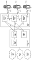
도 1은, 예시적인 UE가 다수의 빔들 상에서 DCI를 모니터링하는 하는 것을 예시한다.
도 2는, 모니터링된 리소스들 내에서 업데이트되는 UE에 대한 예시적인 BPL을 예시한다.
도 3은, 모니터링된 리소스에서의 변경을 초래하는 BPL에서의 예시적인 업데이트를 예시한다.
도 4a는, 공통 검색 공간 DCI 및 UE 특정 검색 공간 DCI에 대한 예시적인 상이한 모니터링 기회들을 예시한다.
도 4b는, 제어 정보를 검출하기 위한 예시적인 방법을 예시한다.
도 5는, 미니-슬롯들 내의 예시적인 모니터링 기회를 예시한다.
도 6a는, CORESET들 및 DCI 위치들이 동일한, 제어 심볼 스위핑을 이용한 다중 빔 제어 시그널링을 위한 예시적인 CORESET 구성들을 예시한다.
도 6b는, CORESET들이 동일하지만 DCI 위치들이 상이한, 제어 심볼 스위핑을 이용한 다중 빔 제어 시그널링을 위한 예시적인 CORESET 구성들을 예시한다.
도 6c는, CORESET들 및 DCI 위치들이 상이한, 제어 심볼 스위핑을 이용한 다중 빔 제어 시그널링을 위한 예시적인 CORESET 구성들을 예시한다.
도 7a는, CORESET들 및 DCI 위치들이 동일한, 슬롯들에 걸친 다중 빔 제어 시그널링을 위한 예시적인 E CORESET 구성들을 예시한다.
도 7b는, CORESET들이 동일하지만 DCI 위치들이 상이한, 슬롯들에 걸친 다중 빔 제어 시그널링을 위한 예시적인 E CORESET 구성들을 예시한다.
도 7c는, CORESET들 및 DCI 위치들이 상이한, 슬롯들에 걸친 다중 빔 제어 시그널링을 위한 예시적인 E CORESET 구성들을 예시한다.
도 8은, DL 승인들을 만드는 상이한 빔들 상의 예시적인 DCI를 예시한다.
도 9는, 차단에 대해 강건할 수 있는 예시적인 DCI 반복을 예시하며; 다수의 DCI가 동일한 승인을 가리킨다.
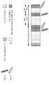
도 10은, SS 블록이 존재하는 예시적인 서브프레임 구조를 예시한다.
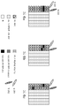
도 11a는, SS 블록 위치 설계의 예시적인 슬롯 구조를 예시한다.
도 11b는, SS 블록 위치 설계의 예시적인 슬롯 구조를 예시한다.
도 11c는, SS 블록 위치 설계의 예시적인 슬롯 구조를 예시한다.
도 11d는, SS 블록 위치 설계의 예시적인 슬롯 구조를 예시한다.
도 11e는, SS 블록 위치 설계의 예시적인 슬롯 구조를 예시한다.
도 11f는, SS 블록 위치 설계의 예시적인 슬롯 구조를 예시한다.
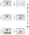
도 12a는, 상이한 DL/UL 심볼 할당을 갖는 예시적인 슬롯 구조를 예시한다.
도 12b는, 상이한 DL/UL 심볼 할당을 갖는 예시적인 슬롯 구조를 예시한다.
도 12c는, 상이한 DL/UL 심볼 할당을 갖는 예시적인 슬롯 구조를 예시한다.
도 13a는, SS 블록과 PDCCH 사이의 예시적인 QCL 가정들을 예시한다.
도 13b는, SS 블록과 PDCCH 사이의 예시적인 QCL 가정들을 예시한다.
도 13c는, SS 블록과 PDCCH 사이의 예시적인 QCL 가정들을 예시한다.
도 14a는, 연속적인, DFT-s-OFDM UL에 대한 예시적인 GF-RS 구성을 예시한다.
도 14b는, 빗(comb)형 GF-RS인, DFT-s-OFDM UL에 대한 예시적인 GF-RS 구성을 예시한다.
도 15는, 다수의 사용자들 사이에 공유될 수 있는 GF 동작에 대한 예시적인 페이로드 구역을 예시한다.
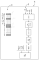
도 16은, 불연속적인 주파수 리소스 할당을 지원하는 예시적인 CP-OFDM 기반 GF-RS 구성을 예시한다.
도 17a는, CP-OFDM으로 GF-RS와 다중화된, 예시적인 GF 제어 구역 구성을 예시한다.
도 17b는, CP-OFDM으로 GF-RS에 후속하는 심볼에 구성된, 예시적인 GF 제어 구역 구성을 예시한다.
도 17c는, DFT-s-OFDM으로 GF-RS에 후속하고 DFT-s-OFDM으로 페이로드와 (D) 다중화된, 예시적인 GF 제어 구역 구성을 예시한다.
도 17d는, DFT-s-OFDM으로 페이로드와 다중화된, 예시적인 GF 제어 구역 구성을 예시한다.
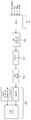
도 18은, UL GF 제어 신호에 대한 예시적인 송신 체인을 예시한다.
도 19는, 셀 ID의 함수인 예시적인 DMRS RE 리소스를 예시한다.
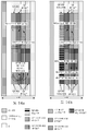
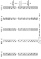
도 20a는, 1 RE/PRB/심볼로 PBC 심볼들 사이에 엇갈려 배치되는, PRB별 PBCH 시그널링을 위한 예시적인 DMRS 밀도들을 예시한다.
도 20b는, 1.5 RE/PRB/심볼로 PBCH 심볼들 사이에 엇갈려 배치되는, PRB별 PBCH 시그널링을 위한 예시적인 DMRS 밀도들을 예시한다.
도 20c는, 1.5 RE/PRB/심볼로 PBCH 심볼들 사이에 엇갈림 없이 배치되는, PRB별 PBCH 시그널링을 위한 예시적인 DMRS 밀도들을 예시한다.
도 20d는, 2 RE/PRB/심볼로 PBCH 심볼들 사이에 엇갈려 배치되는, PRB별 PBCH 시그널링을 위한 예시적인 DMRS 밀도들을 예시한다.
도 20e는, 3 RE/PRB/심볼로 PBCH 심볼들 사이에 엇갈림 없이 배치되는, PRB별 PBCH 시그널링을 위한 예시적인 DMRS 밀도들을 예시한다.
도 20f는, 3 RE/PRB/심볼로 PBCH 심볼들 사이에 엇갈려 배치되는, PRB별 PBCH 시그널링을 위한 예시적인 DMRS 밀도들을 예시한다.
도 21은, PBCH 심볼들에 걸친 DMRS 쌍에 대한 예시적인 OCC를 예시한다.
도 22a는, DMRS가, PRB들 사이에 균일하게 분포되어, PBCH의 PRB들 내에 할당되는 PBCH에 대한 예시적인 DMRS 구성을 예시한다.
도 22b는, DMRS가, PRB들 사이에 균일하게 분포되어 PBCH를 넘어 1개의 PRB에 걸쳐 연장되는, PBCH에 대한 예시적인 DMRS 구성을 예시한다.
도 22c는, DMRS가, PBCH의 가장자리 근처의 PRB들에서 더 조밀하게 PBCH의 PRB들 내에 할당되는, PBCH에 대한 예시적인 DMRS 구성을 예시한다.
도 22d는, DMRS가, 가장자리에서 더 조밀하게 PBCH를 넘어 1개의 PRB에 걸쳐 연장되고, 연장된 PRB 내의 DMRS가 가장자리에 가까운 RE들에만 분포되는, PBCH에 대한 예시적인 DMRS 구성을 예시한다.
도 22e는, 연장된 PRB 내의 DMTS가 덜 조밀하지만 가장자리 PRB보다는 PRB 전체에 걸쳐 분포되는, PBCH에 대한 예시적인 DMRS 구성을 예시한다.
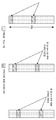
도 23은, 각각의 슬롯이 2개의 SS 블록을 포함하는, NSS_Blk = 64로 이루어진 예시적인 SS 버스트를 예시한다.
도 24는, 빔 기반 DL 제어 시그널링의 방법들 및 시스템들에 기반하여 생성될 수 있는 예시적인 디스플레이(예컨대, 그래픽 사용자 인터페이스)를 예시한다.
도 25a는, 예시적인 통신 시스템을 예시한다.
도 25b는, 예컨대, 무선 송신/수신 유닛(WTRU)과 같은 무선 통신들을 위해 구성된 예시적인 장치 또는 디바이스의 블록도이다.
도 25c는, 제1 예시적인 무선 액세스 네트워크(RAN) 및 코어 네트워크의 시스템 도면이다.
도 25d는, 제2 예시적인 무선 액세스 네트워크(RAN) 및 코어 네트워크의 시스템 도면이다.
도 25e는, 제3 예시적인 무선 액세스 네트워크(RAN) 및 코어 네트워크의 시스템 도면이다.
도 25f는, 통신 네트워크들의 하나 이상의 장치, 이를테면, RAN, 코어 네트워크, 공용 교환 전화 네트워크(PSTN), 인터넷, 또는 다른 네트워크들에서의 특정 노드들 또는 기능적 엔티티들이 구체화될 수 있는 예시적인 컴퓨팅 시스템의 블록도이다.A more detailed understanding can be made from the following description given by way of example in conjunction with the accompanying drawings.
1 illustrates an example UE monitoring DCI on multiple beams.
2 illustrates an example BPL for a UE being updated within monitored resources.
3 illustrates an example update in a BPL resulting in a change in monitored resources.
4A illustrates example different monitoring opportunities for common search space DCI and UE specific search space DCI.
4B illustrates an example method for detecting control information.
5 illustrates an example monitoring opportunity in mini-slots.
6A illustrates example CORESET configurations for multi-beam control signaling using control symbol sweeping where the CORESETs and DCI locations are the same.
6B illustrates example CORESET configurations for multi-beam control signaling with control symbol sweeping, where CORESETs are the same but different DCI locations.
FIG. 6C illustrates example CORESET configurations for multi-beam control signaling using control symbol sweeping with different CORESETs and DCI locations.
7A illustrates example E CORESET configurations for multiple beam control signaling across slots, where the CORESETs and DCI locations are the same.
7B illustrates example E CORESET configurations for multiple beam control signaling across slots, where CORESETs are the same but different DCI locations.
7C illustrates example E CORESET configurations for multiple beam control signaling across slots, with different CORESETs and DCI locations.
8 illustrates an example DCI on different beams making DL grants.
9 illustrates an example DCI repetition that may be robust to blocking; Multiple DCIs indicate the same grant.
10 illustrates an example subframe structure in which an SS block exists.
11A illustrates an example slot structure of an SS block location design.
11B illustrates an example slot structure of an SS block location design.
11C illustrates an example slot structure of an SS block location design.
11D illustrates an example slot structure of the SS block location design.
11E illustrates an example slot structure of an SS block location design.
11F illustrates an example slot structure of the SS block location design.
12A illustrates an example slot structure with different DL / UL symbol assignment.
12B illustrates an example slot structure with different DL / UL symbol assignment.
12C illustrates an example slot structure with different DL / UL symbol assignment.
13A illustrates example QCL assumptions between the SS block and the PDCCH.
13B illustrates example QCL assumptions between the SS block and the PDCCH.
13C illustrates example QCL assumptions between the SS block and the PDCCH.
14A illustrates an example GF-RS configuration for a continuous, DFT-s-OFDM UL.
14B illustrates an example GF-RS configuration for the DFT-s-OFDM UL, which is a comb-shaped GF-RS.
15 illustrates an example payload zone for GF operation that may be shared among multiple users.
16 illustrates an example CP-OFDM based GF-RS configuration supporting discontinuous frequency resource allocation.
17A illustrates an example GF control zone configuration, multiplexed with GF-RS with CP-OFDM.
17B illustrates an example GF control zone configuration, configured in symbols following the GF-RS with CP-OFDM.
17C illustrates an example GF control region configuration, followed by GF-RS with DFT-s-OFDM and (D) multiplexed with payload with DFT-s-OFDM.
17D illustrates an example GF control zone configuration, multiplexed with payload with DFT-s-OFDM.
18 illustrates an example transmission chain for the UL GF control signal.
19 illustrates an example DMRS RE resource as a function of cell ID.
20A illustrates example DMRS densities for PBCH signaling per PRB, staggered between PBC symbols with 1 RE / PRB / symbol.
FIG. 20B illustrates exemplary DMRS densities for PBCH signaling per PRB, staggered between PBCH symbols at 1.5 RE / PRB / symbol.
20C illustrates example DMRS densities for PBCH signaling per PRB, with no gaps between PBCH symbols at 1.5 RE / PRB / symbol.
20D illustrates example DMRS densities for PBCH signaling per PRB, staggered between PBCH symbols with 2 RE / PRB / symbols.
20E illustrates example DMRS densities for PBCH signaling per PRB, interspersed between PBCH symbols with 3 RE / PRB / symbols.
20F illustrates exemplary DMRS densities for PBCH signaling per PRB, interspersed between PBCH symbols with 3 RE / PRB / symbols.
21 illustrates an example OCC for a DMRS pair across PBCH symbols.
FIG. 22A illustrates an exemplary DMRS configuration for a PBCH where the DMRS is distributed evenly among the PRBs and allocated within the PRBs of the PBCH.
FIG. 22B illustrates an exemplary DMRS configuration for a PBCH where the DMRS is uniformly distributed among the PRBs and extends over one PRB beyond the PBCH.
FIG. 22C illustrates an example DMRS configuration for a PBCH where DMRS is allocated within the PRBs of the PBCH more densely in PRBs near the edge of the PBCH.
FIG. 22D illustrates an exemplary DMRS configuration for a PBCH where the DMRS extends more tightly over the PBCH at the edge over one PRB, and the DMRS in the extended PRB is distributed only to the REs close to the edge.
22E illustrates an exemplary DMRS configuration for a PBCH where the DMTS in the extended PRB is less dense but distributed throughout the PRB than the edge PRB.
FIG. 23 illustrates an example SS burst consisting of N SS_Blk = 64, wherein each slot includes two SS blocks.
24 illustrates an example display (eg, graphical user interface) that may be generated based on methods and systems of beam based DL control signaling.
25A illustrates an example communication system.
25B is a block diagram of an example apparatus or device configured for wireless communications, such as, for example, a wireless transmit / receive unit (WTRU).
FIG. 25C is a system diagram of the first exemplary radio access network (RAN) and core network. FIG.
FIG. 25D is a system diagram of a second exemplary radio access network (RAN) and a core network. FIG.
FIG. 25E is a system diagram of the third exemplary radio access network (RAN) and core network. FIG.
FIG. 25F illustrates an example computing system in which specific nodes or functional entities in one or more devices of communication networks, such as a RAN, core network, public switched telephone network (PSTN), the Internet, or other networks, may be embodied. It is a block diagram.
배경기술에서 논의된 바와 같이, NR-PDCCH 송신, GF 송신, 및 PBCH 설계의 일반적인 사용에 관하여 고려되었지만, 구현에 관한 특정 문제들이 해결되어야 한다. 다중 빔 NR-PDCCH 송신에 관하여, UE는, UE가 자신의 NR-PDCCH를 수신할 수 있는 특정 빔들 및 시간 간격들을 지원하도록 구성되어야 한다. DCI 수신을 보장하기 위한 올바른 빔 세트로 UE를 구성하는 방식들이 본원에 개시된다. UL GF 송신에 관하여, gNB는, GF 송신의 존재를 검출하고 대응하는 UE를 정확하게 식별해야 한다. UE ID를 강건하게 식별하는 메커니즘들이 본원에 개시된다. PBCH에 관하여, LTE와 달리, NR에서 어떠한 CRS도 존재하지 않을 수 있으며, 따라서, 1차 동기화 신호(PSS) 및 2차 동기화 신호(SSS)를 획득한 후에 PBCH를 디코딩하기 위해 DMRS의 일부 형태가 사용될 수 있다. PBCH에 대한 채널 추정을 돕는 메커니즘들이 본원에 개시된다. 게다가, PDSCH에 관하여, NR-CSI-RS를 사용하는 채널 품질 추정 및 PDSCH에 대한 채널 추정을 돕는 기준 신호 시퀀스들에 대한 설계가 본원에 개시된다.As discussed in the background, although consideration has been given to the general use of NR-PDCCH transmissions, GF transmissions, and PBCH designs, certain problems with implementation must be addressed. With regard to multi-beam NR-PDCCH transmission, the UE should be configured to support certain beams and time intervals at which the UE can receive its NR-PDCCH. Disclosed herein are ways of configuring the UE with the correct beam set to ensure DCI reception. With regard to the UL GF transmission, the gNB must detect the presence of the GF transmission and correctly identify the corresponding UE. Mechanisms for robustly identifying a UE ID are disclosed herein. With regard to PBCH, unlike LTE, there may be no CRS in NR, so some form of DMRS is decoded to decode PBCH after acquiring primary synchronization signal (PSS) and secondary synchronization signal (SSS). Can be used. Mechanisms that help channel estimation for a PBCH are disclosed herein. In addition, with respect to PDSCH, disclosed herein is a design for channel quality estimation using NR-CSI-RS and reference signal sequences to assist channel estimation for PDSCH.
도 1은, 다수의 빔들 상에서 DCI를 모니터링하는 UE(본원에서 WTRU로 또한 지칭됨)의 예시적인 예시이다. 슬롯 1 및 슬롯 2는 제1 빔(예컨대, 빔(201))을 반송하고, 슬롯 3 및 슬롯 4는 제2 빔(예컨대, 빔(202))을 반송한다. 제1 빔 및 제2 빔은 상이한 공간적 방향들을 가리킨다. 다수의 빔들이 존재할 수 있고 각각의 슬롯은 상이할 수 있거나, 다수의 빔들이 존재할 수 있고 빔들은 동일한 슬롯(예컨대, 슬롯 #0)에서 그러나 상이한 심볼들 상에서 발생할 수 있다. DCI는 슬롯(프레임의 슬롯) 내의 단일 빔에서 또는 슬롯 내의 다수의 빔들 상에서 반송될 수 있다. 상이한 심볼들은 상이한 빔들을 반송할 수 있지만, 주어진 DCI는 단일 빔 또는 다수의 빔들로 한정될 수 있다. 다수의 빔들이 사용될 때, 빔은 DCI를 반송하는 심볼들 중 하나 이상 상에서 발생한다. 뉴머롤로지에 따라, 프레임 내에 상이한 수의 슬롯이 존재할 수 있다. 프레임은 길이가 10 ms일 수 있다. 15 KHz 뉴머롤로지의 경우, 10개의 슬롯이 존재한다. 빔은, 특정 공간적 방향으로의 송신으로서 정의될 수 있다. 슬롯에서의 DCI는 하나의 빔(하나의 공간적 방향) 상에서 송신될 수 있거나, 대안적으로, 슬롯에서의 DCI는 슬롯 내의 특정 수의 심볼이 주어진 빔(공간적 방향)에 대응하는 다수의 빔들(상이한 공간적 방향들) 상에서 송신될 수 있다.1 is an illustrative illustration of a UE (also referred to herein as a WTRU) that monitors DCI on multiple beams.
도 1을 계속 참조하면, UE(예컨대, 도 25a의 WTRU(102c))는 PDCCH를 수신하기 위해 다수의 빔들을 모니터링할 수 있으며, 여기서, PDCCH는 DCI를 포함한다. 모니터링된 빔들은 동일하거나 상이한 송신 수신 포인트(TRP; transmission reception point)들, 예컨대, 도 25a의 기지국(114b)으로부터 비롯될 수 있다. UE는, 스케줄, 예컨대, 구성된 모니터링 기회에 따라, 상이한 빔들을 모니터링할 수 있다. 모니터링 기회는, UE가 자신의 제어 정보(예컨대, 특정 시간 리소스들에서의 DCI)를 찾을 수 있는 시간 리소스들을 정의한다. 도 1은, 상이한 슬롯들 내의 특정 심볼들 상에서 송신되는 2개의 빔(예컨대, 슬롯 #0 내의 빔(201) 및 빔(202)) 상의 NR-PDCCH를 UE가 모니터링하는 예를 도시한다. UE는, 빔 쌍 링크들 둘 모두를 통해 DL 또는 UL 승인들을 수신할 수 있다.With continued reference to FIG. 1, a UE (eg,
빔들 각각에 대한 모니터링된 제어 심볼들의 수는 상이할 수 있는데, NR-PDCCH를 반송하는 일부 빔들이 다른 것들보다 더 빈번하게 시그널링될 수 있지만, UE는, 빔들의 발생과 대응하는 시간 및 주파수 리소스들을 알도록 구성될 수 있다. 본원에 개시된 바와 같이, 모니터링 기회, 예컨대, 리소스들의 빔 발생 패턴 및 타이밍은, RRC, MAC CE, 및 DCI 업데이트들 중 하나 이상을 통해 구성될 수 있다. 이는, 다음의 예시적인 방식들 중 하나로 행해질 수 있다. 리소스들은 시간 리소스들에 대응한다. DCI는, 특정 시간 리소스들 상의 특정 공간적 방향(이를테면, 2개의 슬롯마다 처음 2개 심볼 등)에서 모니터링될 수 있다. 그러므로, 특정 시간에 특정 방향에서 DCI를 모니터링한다. 빔의 공간적 방향은 SSB와 같은 알려진 기준 신호의 방향과 관련된 QCL을 통해 표시될 수 있다. 그러므로, UE는 자신이 관련된 기준 신호를 모니터링할 수 있는 방향과 동일한 방향에서 DCI를 모니터링할 수 있다.The number of monitored control symbols for each of the beams may be different, although some beams carrying the NR-PDCCH may be signaled more frequently than others, although the UE may not be able to obtain time and frequency resources corresponding to the generation of the beams. It can be configured to know. As disclosed herein, monitoring opportunities, such as beam generation pattern and timing of resources, may be configured via one or more of RRC, MAC CE, and DCI updates. This can be done in one of the following exemplary ways. The resources correspond to time resources. DCI may be monitored in a particular spatial direction on specific time resources (eg, the first two symbols per two slots, etc.). Therefore, DCI is monitored in a specific direction at a specific time. The spatial direction of the beam may be indicated via QCL associated with the direction of a known reference signal such as SSB. Therefore, the UE can monitor the DCI in the same direction in which it can monitor the associated reference signal.
제1 예시적인 방식에서, 시간 리소스들은 RRC를 통해 시그널링될 수 있다. 모니터링된 빔은, 이동성, 차단 등으로 인해 빔이 빈번하게 업데이트될 수 있으므로, DCI 또는 MAC CE를 통해 시그널링될 수 있다. 도 2는, 다음의 PDCCH 모니터링 기회: 프레임의 슬롯들 #0, 1, 4, 5, 6, 7, 8, 9의 선행 심볼들에 대해 UE가 구성되는 예를 도시한다. 프레임 #N에서, 심볼들은 도 2에 도시된 바와 같이 빔(201) 및 빔(202)을 반송한다. 빔(201)이 드롭되고 빔(203)이 UE에 대해 구성될 때, UE에 대한 PDCCH 시그널링 시간들은 동일하게 유지되지만, 후속 프레임(프레임 #N+1)의 슬롯 #5 및 슬롯 #8에서 빔(203)으로 빔이 변경된다. UE에 대한 리소스들을 스케줄링하기 위해 반영구적 스케줄링이 사용되고, 주어진 프레임에 대해 리소스들이 이미 UE에 배정된 경우, BPL에서 변경이 발생할 때, DCI는 빔에 대한 업데이트들을 표시할 수 있다. 예컨대, 도 2에서, 슬롯 #4에서의 DCI는, 슬롯 #5와 슬롯 #8 및 향후의 프레임들에서의 빔(203)으로의 변경을 표시한다.In a first example manner, time resources can be signaled via RRC. The monitored beam may be signaled via DCI or MAC CE since the beam may be updated frequently due to mobility, blocking, and the like. 2 shows an example in which the UE is configured for the preceding PDCCH monitoring opportunity: preceding symbols of
제2 예시적인 방식에서, 모니터링하기 위한 빔들은 RRC를 통해 구성되고, 시간 리소스들은 MAC CE 또는 DCI를 통해 업데이트된다. 여기서, PDCCH의 타이밍은, 빔이 업데이트되는 경우 UE에 대해 업데이트될 수 있다. 도 3에서 보이는 바와 같이, 프레임 #N+1에서, UE는 슬롯 #7에서 빔(203)을 모니터링하기 시작하고, 슬롯 #5 및 그 이후에서 빔(201)을 드롭한다. 반영구적 스케줄링이 사용되는 경우, 슬롯 #4에서의 DCI는 빔(203)으로의 전환을 표시할 수 있다. 슬롯 #4가 논의되지만 다른 이전 슬롯들이 또한 가능하다. 빔이 차단(예컨대, 드롭)되는 경우, 일부 동적 표시에 대한 요구가 존재할 수 있다. 시간 기간 동안 차단이 존재할 우려가 있는 경우, 타이밍 리소스를 더 동적으로 업데이트하기를 원할 수 있다.In a second exemplary manner, beams for monitoring are configured via RRC and time resources are updated via MAC CE or DCI. Here, the timing of the PDCCH may be updated for the UE when the beam is updated. As shown in FIG. 3, in frame # N + 1, the UE starts monitoring the
제3 예시적인 방식에서, 시간 리소스들 및 빔들 둘 모두는, 더 많은 레이턴시가 허용될 수 있는 이동성과 같은 시나리오들의 경우, RRC 및 MAC CE를 통해 표시될 수 있다.In a third exemplary manner, both the time resources and the beams can be indicated via RRC and MAC CE in scenarios such as mobility where more latency can be tolerated.
본원에 개시되는 바와 같이, 모니터링 기회들은 상이한 유형들의 CORESET들에 대해 상이할 수 있다. 예컨대, UE 특정 검색 공간 DCI 및 공통 검색 공간 DCI는 구성된 상이한 모니터링 기회들을 가질 수 있는데, 예컨대, 시간 위치 및 빔들이 상이할 수 있다. 예컨대, 도 4a에 예시된 바와 같이, 페이징 수행 DCI는 더 많은 빔들 상에 그리고 더 빈번하게 구성될 수 있는 반면, UE 특정 검색 공간 DCI는 더 적은 빔들 상에서 송신될 수 있다. 주파수 또는 시간 또는 빔 방향은 상이한 유형들의 DCI에 대해 상이할 수 있다. 예컨대, 그룹 공통 PDCCH인 선점 표시는 UE 특정 DCI들보다 더 낮은 주기성으로 송신될 수 있다. 페이징을 위한 DCI는 하나의 유형의 공통 검색 공간에 있다. CORESET들은, 공통 또는 UE 특정 검색 공간들을 포함하도록 유연하게 구성될 수 있다. 특정 CORESET들은, 페이징 DCI가 더 빈번한 리소스들을 요구할 수 있으므로, 도 4에서 보이는 바와 같이 공통 제어 검색 공간만을 포함할 수 있다. UE는, 그것이 UE 특정 검색 공간 DCI를 검출하도록 구성되는지 또는 공통 검색 공간 DCI를 검출하도록 구성되는지에 대응하는 각각의 기회 상에서 CORESET들을 디코딩할 수 있다. 이러한 예에서, 슬롯들 #0, #1, 및 #2는 관심 UE에 공통 검색 공간 DCI를 시그널링하도록 배타적으로 구성될 수 있지만, 이들은 다른 UE들에 UE 특정 검색 공간 DCI를 반송할 수 있다. 프레임 내에 구성된 다른 심볼들은, 관심 UE에 공통 검색 공간 DCI 및 UE 특정 검색 공간 DCI 둘 모두를 반송할 수 있다. 개시된 방법은, UE에 의해 모니터링되도록 요구되는 다수의 위치들이 구성가능하게 되는 것을 허용한다는 것이 이해되어야 한다. 게다가, CORESET들 각각이, 이를테면, CORESET들의 위치, CORESET들의 시간상 발생 패턴, 및 심지어 CORESET의 주파수(예컨대, 전체 캐리어 대역폭을 점유하지는 않음)가 구성가능할 수 있다. 또한, UE는 다수의 빔들 상에서 제어 구역들(예컨대, CORESET)을 수신할 수 있고, 하나의 빔으로부터 다음 빔으로 상이한 시간상 발생 패턴을 가질 수 있다.As disclosed herein, monitoring opportunities may be different for different types of CORESETs. For example, the UE specific search space DCI and the common search space DCI may have different monitoring opportunities configured, eg, the time location and the beams may be different. For example, as illustrated in FIG. 4A, paging performing DCI may be configured on more beams and more frequently, while UE specific search space DCI may be transmitted on fewer beams. The frequency or time or beam direction may be different for different types of DCI. For example, a preemption indication that is a group common PDCCH may be transmitted with lower periodicity than UE specific DCIs. DCI for paging is in one type of common search space. CORESETs can be flexibly configured to include common or UE specific search spaces. Certain CORESETs may only include a common control search space, as shown in FIG. 4, because the paging DCI may require more frequent resources. The UE may decode CORESETs on each opportunity corresponding to whether it is configured to detect a UE specific search space DCI or to detect a common search space DCI. In this example,
도 4b는, 제어 정보를 검출하기 위한 예시적인 방법을 예시한다. 단계(121)에서, 하나 이상의 RRC가 UE에 의해 획득될 수 있다. RRC들은, 구성 정보를 제공하는 데 사용될 수 있는 상위 계층(예컨대, 물리 계층이 아님) 시그널링의 예이다. RRC들은 하나 이상의 TRP로부터 비롯될 수 있다. 단계(122)에서, 단계(121)의 하나 이상의 수신된 RRC에 기반하여, UE는, 하나 이상의 빔에 대해 CORESET들에 대한 하나 이상의 모니터링 기회를 결정할 수 있다. 빔은, 본원에 개시되는 바와 같이, 특정 공간적 방향들로의 TRP의 특정 포트/포트들로부터의 시그널링으로서 고려될 수 있고, 알려진 기준 신호의 공간적 방향과 유사한 공간적 방향을 가질 수 있는데, 예컨대, 빔은 기준 신호에 관하여 공간적 QCL을 가질 수 있으므로, 특정 안테나 구성으로 기준 신호를 수신하는 수신기가 또한, 동일한 수신기 안테나 구성을 사용하여 기준 신호와 공간적 QCL을 갖는 빔을 수신할 수 있다. 단계(123)에서, 단계(122)의 모니터링 기회들에 기반하여, UE는, 제어 정보를 위해 하나 이상의 빔을 모니터링하도록 구성될 수 있다. CORESET들은 RRC에 의해 표시될 수 있는 시간상 발생 패턴을 갖는다. 정보는 빔들 상에서 송신된다. UE는 다수의 빔들을 수신하는 것이 가능할 수 있다. DCI는 중복을 위해 다수의 빔들 상에서 전송되는데, 즉, 하나의 빔이 차단되는 경우 다른 빔이 UE에 도달할 수 있다. 또한, 공간적 다중화가 처리량을 증가시키므로, 다수의 빔들이 DCI를 시그널링하는 데 사용된다. 일단 제어 정보가 수신되면, UE는 제어 정보에 따라 동작하도록 진행하는데, 제어 정보가 승인인 경우, UE는 PDSCH를 수신하거나 PUSCH를 송신한다. 제어 정보가 SFI와 같은 그룹 공통 PDCCH인 경우, UE는 자신의 슬롯 포맷을 조정하고, 제어 정보가 전력 제어 명령인 경우, UE는 자신의 전력을 조정하는 그러한 식이다.4B illustrates an example method for detecting control information. At 121, one or more RRCs may be obtained by the UE. RRCs are an example of higher layer (eg, not physical layer) signaling that can be used to provide configuration information. RRCs may originate from one or more TRPs. In
단계(124)에서, 어떤 후속 시간에, UE는 하나 이상의 업데이트된 RRC를 수신할 수 있다. 단계(124)에서, 하나 이상의 업데이트된 RRC에 기반하여, UE는, 하나 이상의 빔에 대해 CORESET들에 대한 하나 이상의 업데이트된 모니터링 기회를 결정할 수 있다. 단계(125)에서, UE는, 업데이트된 모니터링 기회(들)를 사용하여 모니터링한다. 업데이트된 RRC들은, 단계(122)에서 제공되었던 것과 상이한 모니터링 기회들을 구성하는 것을 유발할 수 있는 것으로 고려된다. 모니터링 기회들은 상이한 유형들의 CORESET들에 대해 상이할 수 있다는 것이 또한 이해되어야 한다(예컨대, 상이한 유형들은, UE 특정 검색 공간, 공통 검색 공간, DCI의 유형들 등을 의미할 수 있음). CORESET 내에 다수의 유형들의 검색 공간들이 존재할 수 있다. 상이한 유형들의 DCI들은 상이한 검색 공간들에서 반송될 수 있다. 상이한 검색 공간들은 상이한 RNTI들을 갖는 DCI들을 반송할 수 있는데, 예컨대, 선점 DCI들은 특정 검색 공간에서 반송될 수 있는 반면, RACH 관련 DCI들은 상이한 검색 공간에서 반송될 수 있다. 상이한 모니터링 기회들은, 그러한 검색 공간들 전부가 공통 검색 공간들인 경우라 하더라도 그들에 대해 구성될 수 있다. 추가로, UE는 상이한 CORESET들에서 상이한 RNTI들을 갖고, 그 CORESET들은 상이한 모니터링 기회들을 갖도록 구성될 수 있으며, 그들 전부가 동시에 발생할 필요는 없다. 제어 정보를 검출하기 위한 이러한 예시적인 방법은 구성들에서의 유연성을 허용할 수 있어서, UE는 상이한 유형들의 DCI들을 상이하게 처리할 수 있다. CORESET 리소스들이 고정되는 LTE와 달리, 이는, UE에 가장 적합한 빔들 상에 CORESET 리소스들을 할당하고, DCI의 유형에 따라 적절한 주기성으로 CORESET 리소스들을 할당하는 유연성을 제공한다(일부 DCI는 다른 것들보다 더 빈번하게 모니터링될 것을 요구할 수 있는데, 예컨대, 선점 DCI는 UE 특정 승인을 제공하는 DCI보다 덜 빈번하게 모니터링될 수 있음). UE는, SSB와 공간적 QCL을 갖는 CORESET를 모니터링하도록 구성될 수 있다.At
도 5는, 미니-슬롯들 내의 예시적인 모니터링 기회를 예시한다. CORESET 리소스들이 미니-슬롯 내에 구성될 수 있어서, 단일 슬롯이 UE가 모니터링할 다수의 CORESET들을 포함할 수 있다. 일반적으로, PDCCH 송신 및 모니터링 기회들이 또한 미니-슬롯(예컨대, 슬롯보다 작고, 어딘가에서 2개 내지 7개의 심볼들을 가짐)에서 발생할 수 있다.5 illustrates an example monitoring opportunity in mini-slots. CORESET resources can be configured in a mini-slot such that a single slot can include multiple CORESETs for the UE to monitor. In general, PDCCH transmission and monitoring opportunities may also occur in mini-slots (e.g., smaller than slots and having 2 to 7 symbols somewhere).
다중 빔 PDCCH 송신을 위한 CORESET들이 아래에서 개시된다. CORESET들은, 다음의 예시적인 경우들에 대해 도시된 바와 같이 다음의 방식들로 구성될 수 있다. 도 6은, PDSCH 및 다른 신호들이 송신되기 전에 PDCCH가 한 번에 스위핑되는 예들을 도시한다. PDCCH는 반복될 수 있고, PDSCH는, PDCCH에 걸친 스위핑에 후속하여 송신될 수 있다. 도 7은, PDCCH 및 PDSCH/PUSCH/PUCCH의 슬롯들에 걸쳐 빔들이 스위핑하는 예들을 도시한다. 도 6에서, CORESET는, 상이한 빔들 상에서 시그널링되는 다수의 심볼들을 포함할 수 있다. CORESET에는 PDSCH/PUSCH/PUCCH가 후속될 수 있다. 도 7에서, CORESET는, 하나의 빔만을 사용하여 시그널링될 수 있다. 각각의 빔은 상이한 CORESET 상에서 송신될 수 있다.CORESETs for multi-beam PDCCH transmission are disclosed below. CORESETs can be configured in the following ways, as shown for the following example cases. 6 shows examples in which the PDCCH is swept at one time before the PDSCH and other signals are transmitted. The PDCCH may be repeated and the PDSCH may be transmitted following sweeping over the PDCCH. 7 shows examples of sweeping beams across slots of PDCCH and PDSCH / PUSCH / PUCCH. In FIG. 6, CORESET may include a number of symbols signaled on different beams. CORESET may be followed by PDSCH / PUSCH / PUCCH. In FIG. 7, CORESET may be signaled using only one beam. Each beam may be transmitted on a different CORESET.
도 6a 및 도 7a에 도시된 바와 같이, CORESET들은 모니터링된 빔들에 대해 동일할 수 있고, DCI는 동일한 위치에서 발생할 수 있다. DCI에 대한 주파수 위치들은 동일하지만, 시간은 빔(201) 및 빔(202)에 대해 상이하다.As shown in FIGS. 6A and 7A, the CORESETs may be the same for the monitored beams, and the DCI may occur at the same location. The frequency positions for DCI are the same, but the time is different for
도 6b 및 도 7b에 도시된 바와 같이, CORESET들은 모니터링된 빔들에 대해 동일할 수 있지만, DCI는 CORESET 내의 상이한 위치들에서 발생할 수 있다. CORESET들이 동일할 때, CORESET 구성 오버헤드가 더 작다는 것을 유의한다.As shown in FIGS. 6B and 7B, the CORESETs may be the same for the monitored beams, but DCI may occur at different locations within the CORESET. Note that when the CORESETs are the same, the CORESET configuration overhead is smaller.
도 6c 및 도 7c에 도시된 바와 같이, CORESET들은 빔들에 대해 상이한 리소스들 상에 있다. 이는 특히, UE가 상이한 빔들에 대해 상이한 주파수 구역들 상에서 동작할 수 있을 때 적용가능하다. UE는, CORESET 리소스들 및 주기성 및 공간적 QCL 정보로 구성되어 DCI를 모니터링할 수 있다. 구성 절차들은 앞서 논의된 경우들(예컨대, 도 4b)과 유사하다. UE는 그에 따라, 자신의 DCI에 대해, 수신된 신호를 모니터링한다. 모니터링된 리소스들에서 블라인드로 디코딩한 후에 유효한 DCI를 수신할 시, UE는 제어 정보에 따라 동작한다.As shown in FIGS. 6C and 7C, the CORESETs are on different resources for the beams. This is particularly applicable when the UE can operate on different frequency zones for different beams. The UE may be configured with CORESET resources and periodic and spatial QCL information to monitor the DCI. Configuration procedures are similar to those discussed above (eg, FIG. 4B). The UE accordingly monitors the received signal for its DCI. Upon receiving a valid DCI after decoding to blind in the monitored resources, the UE operates according to the control information.
CORESET를 구성하는 상이한 방식들은 다음의 기술적 효과를 갖는다. 도 6에서, UE의 모니터링 기회들이 CORESET에서 교대로 발생하므로, 도 7과 비교하여 더 적은 레이턴시로 DCI를 스위핑하는 것이 가능하다. 도 7에서, CORESET의 구성은 도 6과 비교하여 더 단순하고, 더 적은 오버헤드를 요구할 수 있다. 도 6b, 도 7b를 참조하면, CORESET는 빔들에 걸쳐 동일하다. 이는 특히, CORESET가 광대역인 경향이 있고 UE의 수신 대역폭의 많은 부분을 점유할 때 유용하다. 도 6c 및 도 7c를 참조하면, CORESET(특히, 주파수 구역)는, UE에 대한 채널 특성들을 수용하기 위해 상이한 빔들 상에서 상이할 수 있다.Different ways of configuring CORESET have the following technical effects. In FIG. 6, since the monitoring opportunities of the UE occur alternately in CORESET, it is possible to sweep the DCI with less latency compared to FIG. 7. In FIG. 7, the configuration of CORESET is simpler compared to FIG. 6 and may require less overhead. 6B and 7B, CORESET is the same across the beams. This is especially useful when CORESET tends to be wideband and occupies a large portion of the UE's receive bandwidth. With reference to FIGS. 6C and 7C, CORESET (particularly the frequency domain) may be different on different beams to accommodate channel characteristics for the UE.
도 8은, DL 승인들을 만드는 상이한 빔들 상의 예시적인 DCI를 예시한다. 상이한 빔들 상의 DCI는 상이할 수 있는데, 예컨대, 그들은 상이한 PDSCH 승인들을 만들 수 있다. 도 8에 도시된 바와 같이, UE는 빔(201) 및 빔(202)을 모니터링하고, 대응하는 DCI들 상에서 상이한 DL 승인들을 수신한다. 여기서, DL 배정들은, 상이한 하이브리드 자동 반복 요청(HARQ) 프로세스들에 대한 것이거나 또는 HARQ 프로세스의 상이한 중복 버전(RV)들 또는 HARQ 프로세스의 동일한 RV(예컨대, 강건성 또는 신뢰성을 위한 것임)에 대한 것일 수 있다. 신뢰성은 더 낮은 BLER을 암시할 수 있고, 강건성은 (예컨대, 차단되지 않는) 링크를 갖는 것에 관하여 고려될 수 있다.8 illustrates an example DCI on different beams making DL grants. DCI on different beams may be different, for example, they may make different PDSCH grants. As shown in FIG. 8, the UE monitors
도 9는, 차단에 대해 강건할 수 있는 예시적인 DCI 반복을 예시하며; 다수의 DCI들이 동일한 승인을 가리킨다. DCI는 차단에 대한 증가된 강건성 및 더 큰 신뢰성을 위해 상이한 빔들 상에서 반복될 수 있다. 그러므로, UE가 하나의 빔 상의 DCI를 올바르게 디코딩하는 데 실패하는 경우, UE는 다른 빔 상의 DCI를 여전히 성공적으로 디코딩한다. 예컨대, DCI는 빔(201) 및 빔(202) 상에서 반복되고, 둘 모두는 도 9에 도시된 바와 같이 슬롯-교차(cross-slot) DL 승인을 표시한다. 여기서, UE는, 빔(201) 및 빔(202) 상의 PDCCH를 모니터링하도록 구성된다. 빔(201) 및 빔(202)은 동일한 승인을 만들고 있다. 또한, 도 9를 참조하면, UE가 적어도 하나의 DCI를 수신할 가능성이 높도록, DCI가 (특히 상이한 빔들 상에서) 반복된다는 것이 이해되어야 한다. 반복된 DCI들이 승인을 제공할 때, DCI들 모두가 승인에 대한 동일한 리소스 세트를 표시할 수 있다. 가능한 이점은, UE가 적어도 하나의 DCI를 수신하는 것을 보장할 수 있다는 것이다.9 illustrates an example DCI repetition that may be robust to blocking; Multiple DCIs indicate the same grant. DCI can be repeated on different beams for increased robustness to blocking and greater reliability. Therefore, if the UE fails to decode the DCI on one beam correctly, the UE still successfully decodes the DCI on the other beam. For example, DCI is repeated on
도 10은, SS 블록이 존재하는 예시적인 서브프레임 구조를 예시한다. 여기서, 슬롯들의 상세한 구조는 SS 블록을 포함할 수 있다. 하나의 서브프레임에서, 도 10에 도시된 바와 같이, 2개의 슬롯 둘 모두가 SS 블록을 포함할 수 있거나, 하나만이 SS 블록을 포함한다. 이러한 예에서, 서브프레임 2의 슬롯 2는 SS 블록을 포함하지 않으며, 그것은 PDSCH, PUSCH 등일 수 있다. 각각의 SS 블록은, UE가 자신의 초기 동기화를 행하기 위해 찾아야 할 송신을 포함할 수 있다. SS 블록에 대한 전형적인 사용은, 각각의 SS 블록이 하나의 빔인 것이다. 그러므로, UE가 이러한 상이한 SS 블록들에 걸쳐 스위핑하고, SS 블록들 중 하나 또는 2개 또는 다른 서브세트 상에서 청취할 수 있다고 결정하는 경우, UE는, 자신이 공간적으로 특정 방향들에서 청취할 수 있는 특정 수신기 구성에 대해 알게 된다.10 illustrates an example subframe structure in which an SS block exists. Here, the detailed structure of the slots may include an SS block. In one subframe, as shown in FIG. 10, both slots may include an SS block, or only one includes an SS block. In this example,
NR에서, 슬롯의 길이는 7개 심볼 또는 14개 심볼일 수 있다. 프론트 로딩(front load)된 PDCCH는 1개 내지 3개 심볼(들)일 수 있다. SS 블록은, 하나의 심볼 PSS, 하나의 심볼 SSS, 및 2개의 심볼 PBCH를 포함하는 4개의 심볼을 점유한다. 슬롯 내의 SS 블록의 위치는: 1) 제4 심볼 내지 제 7 심볼의 고정된 위치일 수 있거나; 또는 2) 프론트 로딩된 PDCCH 심볼(들)에 후속할 수 있다.In NR, the length of the slot may be seven symbols or fourteen symbols. The front loaded PDCCH may be one to three symbol (s). The SS block occupies four symbols including one symbol PSS, one symbol SSS, and two symbol PBCHs. The position of the SS block in the slot is: 1) can be a fixed position of the fourth to seventh symbols; Or 2) may be followed by the front loaded PDCCH symbol (s).
7개 심볼 슬롯의 경우에 대해, 슬롯 구조가 도 11a 내지 도 11f에 도시된다. 도 11a, 도 11b, 및 도 11c에서, SS 블록은, 1개 내지 3개 심볼의 프론트 로딩된 PDCCH 경우들에 대해, 제4 심볼 내지 제7 심볼에 위치된다. 도 11a, 도 11d, 도 11e, 및 도 11f에서, SS 블록은, 프론트 로딩된 PDCCH 옆의 심볼들에 위치된다. 동일한 위치 원리들이 14개 심볼 슬롯의 경우에 적용된다.For the case of seven symbol slots, the slot structure is shown in FIGS. 11A-11F. 11A, 11B, and 11C, the SS block is located in the fourth to seventh symbols for front loaded PDCCH cases of one to three symbols. 11A, 11D, 11E, and 11F, the SS block is located in symbols next to the front loaded PDCCH. The same positioning principles apply to the case of 14 symbol slots.
SS 블록 옆의 심볼들의 사용은, 남아 있는 심볼들의 수(N)에 의존한다. 예컨대, N < 2인 경우, 남아 있는 심볼은 DL에 대해서만 사용될 수 있으며, 예가 도 11d로서 도시된다.The use of symbols next to the SS block depends on the number N of symbols remaining. For example, if N <2, the remaining symbols can only be used for DL, an example is shown as FIG. 11D.
N = 2인 경우, 심볼들은 DL 단독 및 UL 단독 둘 모두에 대해 사용될 수 있다. 도 11d는, DL 단독 사용 경우에 대한 예를 도시한다. 도 11f는, UL 단독 사용 경우에 대한 예를 도시한다.If N = 2, symbols can be used for both DL alone and UL alone. 11D shows an example of the DL only use case. 11F shows an example for the UL alone use case.
N > 2인 경우, 심볼들은 DL 단독, UL 단독, 및 DL + UL에 대해 사용될 수 있다. (N > 2인 상황은 14개 심볼 슬롯의 경우에 발생한다) 도 12a는, DL 단독 사용 경우에 대한 예를 도시한다. 도 12b는, DL + UL 사용 경우에 대한 예를 도시한다. 도 12c는, UL 단독 사용 경우에 대한 예를 도시한다.If N> 2, the symbols may be used for DL alone, UL alone, and DL + UL. (The situation where N> 2 occurs in the case of 14 symbol slots.) FIG. 12A shows an example of a DL only use case. 12B shows an example for a DL + UL use case. 12C shows an example for the UL alone use case.
NR에서, 슬롯 내의 PDCCH 및 SS 블록은 동일한 빔들 상에서 또는 상이한 빔들 상에서 송신될 수 있다. 심지어 PDCCH의 모든 각각의 심볼에 대해, 상이한 심볼들이 상이한 빔들 상에서 송신될 수 있다. 따라서, PDCCH와 SS 블록 사이에 어떠한 QCL 가정도 이루어질 수 없다. SS 블록 및 PDCCH를 반송하는 하나의 슬롯 내에서, 공간적 방향에 대한 관계는 알려져 있지 않을 수 있다. 그러나, 유사한 시나리오들에서, PDCCH와 SS 블록 사이의 QCL 관계가 활용되어 오버헤드 및 계산 복잡도를 감소시킬 수 있다. 도 13a 내지 도 13c는, SS 블록과 PDCCH 사이의 예시적인 QCL 가정들을 예시한다. 도 13에서, 블록 내의 SS 블록과 PDCCH 사이에 QCL 관계가 존재하며, 이는 7개 심볼 슬롯의 경우 및 14개 심볼 슬롯의 경우에 적용된다In NR, the PDCCH and SS block in the slot may be transmitted on the same beams or on different beams. Even for every respective symbol of the PDCCH, different symbols may be transmitted on different beams. Thus, no QCL assumption can be made between the PDCCH and the SS block. Within one slot carrying an SS block and a PDCCH, the relationship to spatial direction may not be known. However, in similar scenarios, the QCL relationship between the PDCCH and the SS block can be utilized to reduce overhead and computational complexity. 13A-C illustrate exemplary QCL assumptions between the SS block and the PDCCH. In FIG. 13, there is a QCL relationship between the SS block and the PDCCH in the block, which applies to the case of seven symbol slots and the case of 14 symbol slots
7개 심볼 슬롯의 경우를 예로서 사용하면, 도 13a에서, PDCCH 및 SS 블록은 동일한 빔 상에서 송신된다. 이러한 경우에서, 공간적 QCL 파라미터, 및 {지연 확산, 도플러 확산, 도플러 편이, 평균 이득, 또는 평균 지연}에 관한 대규모 파라미터들의 QCL 둘 모두가 SS 블록과 PDCCH 사이에 유지될 수 있다. 도 13b에서, SS 블록이 하나의 빔 상에서 송신되고, 1개 내지 3개 심볼일 수 있는 PDCCH가 다른 빔 상에서 송신된다. 이러한 2개의 빔은, 이러한 예에 대해, 동일한 방향으로 송신되고, 공간적 QCL 파라미터들에 관하여 QCL될 수 있다. 심볼 1 내지 심볼 3(#0 내지 #2는 PDCCH임)은 심볼 4 내지 심볼 7(#3 내지 #6)보다 더 좁은 빔 상에 있을 수 있다. 도시된 바와 같이, 공간적 파라미터들 및 비-공간적(예컨대, 대규모) 파라미터들에 기반하여 QCL될 수 있다. 도 13c에서, PDCCH를 송신하기 위해 2개 또는 3개의 심볼이 사용될 수 있다. 이러한 2개 또는 3개의 심볼은, 이러한 예에서, 동일한 방향을 가리키지만 SS 블록에 사용된 빔과 상이한 빔들(약간 상이한 각도들) 상에서 송신된다. 이러한 경우에서, PDCCH에 대해 사용된 빔들은 공간적 QCL 파라미터들에 관하여 서로 QCL될 수 있고, 모든 빔들은 공간적 QCL 파라미터들에 관하여 SS 블록에 대해 사용된 빔과 QCL될 수 있다. PDCCH와 SS 블록 사이의 이러한 QCL 관계들의 정보를 이용하여, UE가, SS 블록에 대해 사용된 동일한 빔을 사용하여 PDCCH를 수신할 수 있거나, UE가, SS 블록으로부터 수집된 정보를 재사용하여 PDCCH에 대한 채널 추정을 행할 수 있는 그러한 식이다. 매우 많은 상이한 시나리오들이 존재하고, NR에서 어떠한 기본 QCL 가정도 이루어질 수 없으므로, PDCCH와 SS 블록 사이의 QCL 관계는 TRP로부터의 RRC 시그널링 또는 MAC CE를 통해 UE에 표시될 수 있다. 표시는 명시적 또는 암시적일 수 있다. UE에 대해 QCL 정보가 구성되는 것은 명시적인 것으로 고려될 수 있다. 예컨대, UE 특정 CORESET는 기준 신호들에 대한 특정 QCL 관계들로 구성된다. 그러므로, UE는 이러한 정보를 사용하여 대응하는 DCI들을 수신한다. QCL 정보가 선험적으로 알려져 있는 것은 암시적인 것으로 고려될 수 있다. 예컨대, RMSI CORESET는 UE에 의해 검출되는 SSB와 암시적으로 QCL이다.Using the case of seven symbol slots as an example, in Fig. 13A, the PDCCH and SS blocks are transmitted on the same beam. In this case, both the spatial QCL parameter and the QCL of the large parameters regarding {delay spread, Doppler spread, Doppler shift, average gain, or average delay} may be maintained between the SS block and the PDCCH. In FIG. 13B, an SS block is transmitted on one beam, and a PDCCH, which may be one to three symbols, is transmitted on another beam. These two beams may be transmitted in the same direction and QCL in terms of spatial QCL parameters, for this example.
NR은, UL 무승인 송신들을 가능하게 하기 위해 DL 및 UL 상에서 제어 시그널링을 사용할 수 있다. 무승인 UL 송신의 식별 및 무승인 송신을 수행하는 UE의 식별을 위한 방법이 본원에 개시된다. 무승인 송신의 존재를 식별하기 위해 기준 신호(RS) 시퀀스가 사용될 수 있다. 이후, 이러한 RS는 무승인 기준 신호(GF-RS)로 지칭된다. GF-RS는 각각의 무승인 UE에 배정될 수 있다. 일반적으로, 시퀀스들은, UE들 사이의 교차 상관을 최소화하기 위해 직교 또는 준 직교일 수 있다. 특정 시간 주파수 리소스들 및 순환 편이를 갖는 특정 GF-RS는, GF 페이로드에 대한 특정 시간 주파수 리소스들에 대응할 수 있다. GF-RS는 가능한 경우마다 채널 추정에 대해 사용될 수 있다.The NR may use control signaling on the DL and UL to enable UL unauthorized transmissions. Disclosed herein are methods for identification of unauthorized UL transmissions and identification of a UE performing an unauthorized transmission. Reference signal (RS) sequences may be used to identify the presence of unauthorized transmissions. This RS is hereinafter referred to as an unauthorized reference signal (GF-RS). The GF-RS may be assigned to each unauthorized UE. In general, the sequences may be orthogonal or quasi-orthogonal to minimize cross correlation between UEs. Specific GF-RSs with specific time frequency resources and cyclic shift may correspond to specific time frequency resources for the GF payload. The GF-RS can be used for channel estimation whenever possible.
DFT-s-OFDM 기반 UL의 경우, GF-RS는 자도프-추(ZC; Zadoff-Chu) 시퀀스들의 형태일 수 있다. 이들은, 피크 대 평균 전력 비(PAPR)를 한정되게 유지하기 위해, 반복 인자 N을 이용하여 심볼 내의 주파수 리소스들 상에 빗형 방식으로 배정될 수 있다. N = 1일 때, 시퀀스는 연속적 리소스 요소(RE)들을 사용했다.For DFT-s-OFDM based UL, the GF-RS may be in the form of Zadoff-Chu (ZC) sequences. These can be assigned in a comb fashion on the frequency resources within a symbol using the repetition factor N to keep the peak to average power ratio (PAPR) limited. When N = 1, the sequence used consecutive resource elements (REs).
도 14a 내지 도 14b는, DFT-s-OFDM UL에 대한 예시적인 GF-RS 구성을 예시한다. 도 14a에서, N = 1이 사용되고, UE의 GF-RS는 심볼 내의 모든 할당된 주파수 리소스들을 점유할 수 있다. 상이한 순환 편이들을 갖는 다수의 GF-RS 시퀀스가 그러한 리소스들에서 동시에 시그널링될 수 있고, 각각의 시퀀스는, 페이로드가 반송되는 미리 구성된 리소스 세트에 대응한다. 도 14b에서, N = 2가 사용되고, GF-RS 시퀀스들은 인터리빙된다. 특정 GF-RS가 송신되지 않을 때, 대응하는 페이로드 리소스들은 비어 있다.14A-14B illustrate an exemplary GF-RS configuration for the DFT-s-OFDM UL. In FIG. 14A, N = 1 is used, and the GF-RS of the UE may occupy all allocated frequency resources in the symbol. Multiple GF-RS sequences with different cyclic shifts can be signaled simultaneously in such resources, each sequence corresponding to a preconfigured set of resources with which the payload is carried. In FIG. 14B, N = 2 is used and GF-RS sequences are interleaved. When a particular GF-RS is not transmitted, the corresponding payload resources are empty.
일반적으로, GF 페이로드들은 각각의 순환 편이에 대응하는 예비된 리소스들을 가질 수 있어서, GF-RS가 중첩되는 경우 어떠한 충돌도 발생하지 않는다. 대안적으로, 도 15는, 다수의 사용자들 사이에 공유될 수 있는 GF 동작에 대한 예시적인 페이로드 구역을 예시하며, 여기서, GF 페이로드들은 특정 리소스 세트 내에서 서로 충돌할 수 있다.In general, GF payloads may have reserved resources corresponding to each cyclic shift, so that no collision occurs when GF-RSs overlap. Alternatively, FIG. 15 illustrates an example payload zone for GF operation that may be shared among multiple users, where the GF payloads may collide with each other within a particular resource set.
도 15에서, 페이로드 리소스들은 다수의 GF UE들에 의해 공유되고, 직교 확산 코드들 또는 낮은 레이트 코드들이 사용되어 UE들을 직교화할 수 있다. In FIG. 15, payload resources are shared by multiple GF UEs, orthogonal spreading codes or low rate codes may be used to orthogonalize the UEs.
순환 프리픽스-OFDM(CP-OFDM) 기반 UL 무승인 동작의 경우, GF-RS는, 페이로드의 주파수 다이버시티를 허용하기 위해 주파수에서 불연속적일 수 있다. RS는, 무승인 송신의 신속한 검출을 가능하게 하기 위해 프론트 로딩된다. 예가 도 16에 도시된다. 페이로드 구역은 주파수에서 GF-RS와 다중화될 수 있다.For cyclic prefix-OFDM (CP-OFDM) based UL unauthorized operation, the GF-RS may be discontinuous in frequency to allow frequency diversity of the payload. The RS is front loaded to enable fast detection of unauthorized transmissions. An example is shown in FIG. 16. The payload region can be multiplexed with GF-RS in frequency.
이용가능한 시퀀스들 또는 리소스들의 수와 비교하여 UE들의 수가 매우 클 수 있는 상황들이 존재할 수 있기 때문에, 다수의 UE들이 동일한 리소스들을 배정받을 수 있다. 그러므로, UE 식별은, 무승인 송신의 존재의 식별 후에 이루어져야 한다. UE ID, 이를테면, C-RNTI(16 비트)는 페이로드와 함께 송신될 수 있다. 대안적으로, 네트워크는, 16 비트보다 적은 (예컨대, 8 비트의) 무승인 RNTI(GF-RNTI)를 UE들에 배정할 수 있고, 이러한 GF-RNTI는 페이로드와 함께 송신될 수 있다. 도 17a 내지 도 17d는 예시적인 GF 제어 구역 구성을 예시한다. 도 17a 및 도 17b는, UE의 GF UL 제어 리소스들이 페이로드 구역의 선행 심볼들에 있는 CP-OFDM의 예들을 도시한다. 도 17c 및 도 17d는, GF UL 제어 리소스들이 페이로드와 다중화된 완전한 심볼 또는 부분적 심볼 리소스들과 연속적인 DFT-s-OFDM에 대한 예들을 도시한다.Since there may be situations where the number of UEs may be very large compared to the number of available sequences or resources, multiple UEs may be allocated the same resources. Therefore, UE identification should be made after identification of the presence of unauthorized transmission. The UE ID, such as C-RNTI (16 bits), may be transmitted with the payload. Alternatively, the network may assign less than 16 bits (eg, 8 bits) of unauthorized RNTI (GF-RNTI) to the UEs, which may be transmitted with the payload. 17A-17D illustrate exemplary GF control zone configurations. 17A and 17B show examples of CP-OFDM in which GF UL control resources of the UE are in preceding symbols of the payload region. 17C and 17D show examples for DFT-s-OFDM in which GF UL control resources are contiguous with the payload and with complete symbol or partial symbol resources.
UL GF 제어 정보, 이를테면, 페이로드 크기, MCS, HARQ 프로세스 ID, RV 등이 함께 인코딩될 수 있다. UE ID는 제어 정보에 부착된 CRC에 대한 마스크로서 적용될 수 있다. 페이로드 크기에 따라, 리드 멀러(RM; reed muller) 또는 극 코딩이 제어 정보에 적용될 수 있다. 도 18은, UE ID가 페이로드와 함께 전송될 수 있는 방식의 예들을 도시한다. 제어 정보에 대해 직교 위상 편이 변조(QPSK)가 사용될 수 있다. 레이트 매칭은, 이용가능한 GF 리소스들의 양, 데이터 페이로드에 대해 사용되는 MCS, 및 페이로드와 UL 제어에 대한 표적 블록 오류율(BLER)에 의존할 수 있다. 추가로, 도 18과 관련하여, 도 18은 DL 제어 정보의 인코딩을 도시하는 것으로 고려될 수 있다. UE는, GF 송신에 대한 것과 유사한 방식으로 UL 제어 정보를 송신할 수 있다. 단계(251)에서, 페이로드는, MCS, TBS(전송 블록의 크기) 등을 포함할 수 있다. 단계(252)에서, 페이로드에 적용된 CRC는 GF-RNTI로 마스킹될 수 있다. 이러한 마스킹된 CRC의 비트들은 페이로드에 부착될 수 있다. 비트들은, 인코딩되고(단계(253)), 레이트 매칭되고(단계(254)), 변조되어 PUSCH와 같은 다른 신호들과 다중화되고(단계(255)), UL에서 송신될 수 있다. gNB는, GF-RNTI를 성공적으로 디코딩하는 것에 의존하여 UL 제어 정보를 검출할 수 있다.UL GF control information such as payload size, MCS, HARQ process ID, RV, etc. may be encoded together. The UE ID may be applied as a mask for the CRC attached to the control information. Depending on the payload size, reed muller (RM) or pole coding may be applied to the control information. 18 shows examples of how a UE ID can be sent with a payload. Quadrature Phase Shift Keying (QPSK) may be used for the control information. Rate matching may depend on the amount of GF resources available, the MCS used for the data payload, and the target block error rate (BLER) for payload and UL control. In addition, with respect to FIG. 18, FIG. 18 may be considered to illustrate the encoding of DL control information. The UE may transmit UL control information in a manner similar to that for GF transmission. In
무승인 송신들에서의 DL 제어 시그널링. DCI의 가능한 내용들의 목록이 아래에 있다. DCI를 통한 동적 시그널링은, 무승인 시그널링을 위한 다음의 파라미터들: 1) 하나 이상의 슬롯에서 무승인 송신을 인에이블링 또는 디스에이블링하는 것; 2) 하나 이상의 슬롯에서 무승인 시그널링에 대해 사용될 수 있는 UL 시간 및 주파수 리소스들을 구성하는 것; 3) 무승인 시그널링에 대해 사용될 수 있는 단일 DMRS 리소스 또는 DMRS 리소스들의 풀을 표시하는 것; 또는 4) UE들이 무승인 시그널링에 대해 사용할 수 있는 가능한 변조 및 코딩 방식들을 표시하는 것 중 하나 이상을 구성하는 데 사용될 수 있다. 예컨대, 제4 파라미터에 관하여, gNB는, (무승인 리소스들에서의 인지된 UL 간섭에 따라) 무승인 송신들에 대해 사용될 수 있는 제한된 유효한 MCS 세트를 표시할 수 있다. 그리고, gNB는, 유효한 MCS 목록에 대해, 수신된 승인없는 신호들을 블라인드로 디코딩할 수 있다. UL 상에서 MCS의 어떠한 명시적 표시도 요구되지 않는다. 대안적으로, UE는, 유효한 MCS 세트가 작을 수 있으므로, 몇 비트를 사용하여 MCS를 표시할 수 있다. 제5 파라미터는, UE가 송신에 대한 적절한 MCS를 선택할 수 있게 하기 위한 전력 수준 또는 등가의 메트릭을 표시하는 것을 포함할 수 있다. 예컨대, 제5 파라미터에 관하여, 무승인 송신이 eMBB 송신들을 반송하는 리소스들에서 발생할 수 있는 경우, eMBB 송신으로 인한 간섭 수준이 gNB에 의해 무승인 UE들에 전달될 수 있어서, 무승인 UE들은 자신의 변조 및 코딩을 그에 따라 조정할 수 있다.DL control signaling in unauthorized transmissions. Below is a list of possible contents of the DCI. Dynamic signaling over DCI may include the following parameters for unauthorized signaling: 1) enabling or disabling unauthorized transmission in one or more slots; 2) configuring UL time and frequency resources that can be used for unauthorized signaling in one or more slots; 3) indicating a single DMRS resource or pool of DMRS resources that can be used for unauthorized signaling; Or 4) indicating one or more of the possible modulation and coding schemes that UEs can use for unauthorized signaling. For example, with respect to the fourth parameter, the gNB may indicate a limited valid MCS set that may be used for unauthorized transmissions (according to the recognized UL interference in unauthorized resources). And, the gNB may blindly decode the received unauthorized signals, for a valid MCS list. No explicit indication of the MCS on the UL is required. Alternatively, the UE may indicate the MCS using a few bits since the valid MCS set may be small. The fifth parameter may include indicating a power level or equivalent metric for enabling the UE to select an appropriate MCS for transmission. For example, with respect to the fifth parameter, if an unauthorized transmission can occur in resources carrying eMBB transmissions, the interference level due to the eMBB transmission can be communicated to the UEs disapproved by the gNB so that the unauthorized UEs themselves Can be adjusted accordingly.
PBCH에 대한 DMRS 설계는: 1) DMRS 시퀀스가 셀 ID의 함수라는 것; 2) DMRS 위치가 셀 ID의 함수라는 것(예컨대, 도 19에 도시되며, 심볼 내의 DMRS의 RE가 셀 ID에 따라 변할 수 있음); 또는 3) DMRS 시퀀스 또는 리소스들이 SS 블록 타이밍의 함수일 수 있다는 것을 포함할 수 있다.DMRS design for PBCH includes: 1) DMRS sequence is a function of cell ID; 2) that the DMRS location is a function of the cell ID (eg, shown in FIG. 19, where the RE of the DMRS in a symbol may change depending on the cell ID); Or 3) DMRS sequence or resources may be a function of SS block timing.
NR은, DMRS의 밀도를 PBCH Res.의 8 % 내지 33 %의 범위로 특정할 수 있다. 모의실험은, 범위 내의 밀도가 유용하다는 것을 나타낸다. 도 20은, 심볼당 RB당 1 RE 내지 심볼당 RB당 3 RE의 범위의 상이한 RS 밀도들의 예를 도시한다. 또한, 원하는 DMRS 밀도는, 2개의 PBCH 심볼들 사이에 DMRS RE들을 균등하게 분포시킴으로써 달성된다. 2개의 심볼에서의 DMRS RE들은 서로에 대해 엇갈려 배치(도 20a, 도 20b, 도 20d, 도 20f)될 수 있거나 또는 동일한 주파수 리소스들을 점유(도 20c, 도 20e)할 수 있다.NR can specify the density of DMRS in the range of 8% to 33% of PBCH Res. The simulation shows that the density within the range is useful. 20 shows examples of different RS densities ranging from 1 RE per RB per symbol to 3 RE per RB per symbol. In addition, the desired DMRS density is achieved by evenly distributing the DMRS REs between the two PBCH symbols. DMRS REs in two symbols may be staggered with respect to one another (FIGS. 20A, 20B, 20D, 20F) or may occupy the same frequency resources (FIGS. 20C, 20E).
또한, 동일한 DMRS 시퀀스들은 두 심볼들 모두에서 사용될 수 있고, OCC는 도 21에 도시된 바와 같은 2개의 심볼에 걸친 DMRS의 쌍들에 걸쳐 사용되어 빔 간, 셀 내, 또는 셀 간 간섭을 감소시킬 수 있다. 이러한 예에서, 가중치들 [1, -1]을 갖는 OCC가 2개의 심볼에서의 DMRS RE에 적용된다.In addition, the same DMRS sequences can be used in both symbols, and OCC can be used across pairs of DMRS across two symbols as shown in FIG. 21 to reduce inter-beam, intra-cell, or inter-cell interference. have. In this example, an OCC with weights [1, -1] is applied to the DMRS RE in two symbols.
도 22a 내지 도 22e는 PBCH에 대한 예시적인 DMRS 구성을 예시한다. PBCH는 심볼당 24개의 RB를 점유할 수 있다. 채널 추정은, 도 22a에 도시된 바와 같은 PBCH-DMRS의 불연속성으로 인해, 이러한 24개의 RB 구역의 가장자리들에서 불량할 수 있다. PBCH의 대역 가장자리들에서의 채널 추정을 향상시킬 수 있는 구현들이 아래에(예컨대, 도 22b 내지 도 22e에) 개시된다.22A-22E illustrate an exemplary DMRS configuration for a PBCH. The PBCH may occupy 24 RBs per symbol. Channel estimation may be poor at the edges of these 24 RB zones due to the discontinuity of the PBCH-DMRS as shown in FIG. 22A. Implementations that can improve channel estimation at the band edges of the PBCH are disclosed below (eg, in FIGS. 22B-22E).
도 22b에서, DMRS는, PRB들 사이에 균일하게 분포되어 PBCH를 넘어 1개의 PRB에 걸쳐 연장될 수 있다. PBCH에 대한 DMRS 리소스들은 24개의 RB를 넘어 연장될 수 있다. 이러한 연장된 RB들에서의 신호들은, PBCH DMRS를 수용하도록 레이트 매칭되거나 펑처링될 수 있다. 도 22b는 그러한 예를 도시한다. DMRS 리소스들은 가외의 RB들을 통해 부분적으로 또는 완전히 연장될 수 있다.In FIG. 22B, the DMRS may be uniformly distributed between the PRBs and extend over one PRB beyond the PBCH. DMRS resources for the PBCH may extend beyond 24 RBs. Signals in these extended RBs may be rate matched or punctured to accommodate PBCH DMRS. 22B shows such an example. DMRS resources may be partially or fully extended through extra RBs.
도 22c에서, DMRS는, PBCH의 PRB들 내에 할당될 수 있지만 PBCH의 가장자리 근처의 PRB들에서 더 조밀하다. DMRS 리소스들은, 도 22c에서 보이는 바와 같이, 가장자리들 근처의 RB들에서 더 조밀할 수 있으며, 여기서, 가장자리에서의 RB는 3 DMRS RE/RB/심볼을 갖는 반면, 가장자리에 있지 않은 RB들은 2 DMRS RE/RB/심볼만을 반송한다. DMRS는 가장자리가 아닌 구역에서의 RB들과 비교하여 가장자리에 있는 RB에서 더 조밀하다. 밀도는, 심볼당 RN당 DMRS RE들의 수에 의해 측정될 수 있다.In FIG. 22C, the DMRS may be allocated within the PRBs of the PBCH but is denser in the PRBs near the edge of the PBCH. DMRS resources may be denser at RBs near the edges, as shown in FIG. 22C, where the RB at the edge has 3 DMRS RE / RB / symbols, while the RBs not at the edge are 2 DMRS Only RE / RB / symbols are returned. DMRS is denser at the RB at the edge compared to the RBs at the non-edge zone. Density can be measured by the number of DMRS REs per RN per symbol.
가변 밀도 및 연장된 DMRS 할당 둘 모두가 도 22d 및 도 22de에서 도시된 바와 같이 적용될 수 있다. 도 22d에서, 연장된 구역에서의 DMRS는 대역 가장자리 RB보다 (RB당 기준으로) 더 낮은 밀도를 갖고, 그 RB에서의 DMRS RE들을 부분적으로 점유한다. 도 22e에서, 연장된 구역에서의 DMRS는 대역 가장자리 RB보다 (RB당 기준으로) 더 낮은 밀도를 갖지만, RB의 대역폭에 걸친 RE들을 점유한다. 연장된 구역에서 DMRS RE들이 넓을수록, 채널 추정에서의 대역 가장자리 링잉(ringing)의 억제가 양호하다는 것을 유의한다.Both variable density and extended DMRS allocation can be applied as shown in FIGS. 22D and 22D. In FIG. 22D, the DMRS in the extended zone has a lower density (on a per RB basis) than the band edge RB and partially occupies the DMRS REs in that RB. In FIG. 22E, the DMRS in the extended zone has a lower density (on a per RB basis) than the band edge RB, but occupies REs over the bandwidth of the RB. Note that the wider the DMRS REs in the extended zone, the better the suppression of band edge ringing in channel estimation.
SS 버스트 블록 내에서, PBCH 데이터 복조를 위해 PBCH-DMRS가 사용될 수 있다.Within the SS burst block, PBCH-DMRS may be used for PBCH data demodulation.
PBCH에 대한 DMRS 시퀀스 r(m)이 다음에 의해 정의된다.The DMRS sequence r (m) for the PBCH is defined by
![]()
![]()
여기서, c(i)(i = 1, ..., Q)는 PBCH-DMRS에 대한 기본 시퀀스이고, Q는 PBCH DMRS 길이이고, ns는 SS 버스트 세트 내의 SS 블록 ID이다. 기본 시퀀스 c(i)는 골드 시퀀스 또는 m-시퀀스로부터 구축될 수 있다. 다음의 함수를 통해 의사 랜덤 시퀀스 생성기가 초기화될 수 있다.Where c (i) (i = 1, ..., Q) is the base sequence for PBCH-DMRS, Q is the PBCH DMRS length, and n s is the SS block ID in the SS burst set. The base sequence c (i) can be constructed from a gold sequence or an m-sequence. The pseudo random sequence generator can be initialized by the following function.
![]()
![]()
여기서, ![]()
![]()
![]()
![]()
여기서, NSS_Blk는 SS 버스트 세트 내의 SS 블록들의 수이다. SS 버스트 세트 설계, SS 블록, 및 ns를 표시하는 타이밍이 도 23에 주어진다(SCS = 120 KHz로 가정함).Here, N SS_Blk is the number of SS blocks in the SS burst set. The timing for indicating the SS burst set design, the SS block, and n s is given in FIG. 23 (assuming SCS = 120 KHz).
도 23에서, SS 버스트 세트 내의 SS 블록들의 수는 64로 설정되고(예컨대, NSS_Blk = 64), 각각의 시간 슬롯에 2개의 SS 블록이 존재한다. 도 23에서, 이러한 SS 버스트 세트는 4 ms 내에 64개의 빔을 스위핑하는 것을 완료한다. 의사 랜덤 시퀀스 생성기는 다음으로 초기화될 수 있다.In FIG. 23, the number of SS blocks in the SS burst set is set to 64 (eg, N SS_Blk = 64), and there are two SS blocks in each time slot. In FIG. 23, this set of SS bursts completes sweeping 64 beams in 4 ms. The pseudo random sequence generator may be initialized to
![]()
![]()
![]()
![]()
![]()
![]()
여기서, δ=2r-1이고, r은 양의 정수이고, 뉴머롤로지에 의존할 수 있다. 예컨대, r = 4일 때, δ = 15이다. 값 τ는 ![]()
![]()
리소스 요소에 대한 DMRS 시퀀스는 다음의 방법에 의해 설명될 수 있다.The DMRS sequence for a resource element can be described by the following method.
![]()
![]()
여기서, ![]()
![]()
![]()
![]()
여기서, ![]()
![]()
![]()
![]()
게다가, PBCH DMRS는, 전력 부스팅 옵션에 의해 PBCH 데이터와 상이한 전력 할당을 가질 수 있다. 전력 부스팅 표시는 SSS를 통한 시그널링일 수 있다. SSS는 (SSS 상에서의 PBSK 또는 QPSK를 통해) 1 또는 2 비트 정보를 반송하여 PBCH DMRS의 전력 부스팅을 표시할 수 있다. 전력 부스팅(또는 전력 오프셋) 표시는 정보 비트에 의존할 수 있다. 예컨대, BPSK가 사용되는 경우, 0은 전력 부스팅이 없음을 제시할 수 있고, 1은 전력 부스팅이 존재함을 제시할 수 있다. 전력 부스팅 값은 UE에 알려져 있어야 하는데, 예컨대, 미리 정의된 값이어야 한다.In addition, the PBCH DMRS may have a different power allocation than the PBCH data by the power boosting option. The power boosting indication may be signaling via SSS. The SSS may carry one or two bit information (via PBSK or QPSK on the SSS) to indicate power boosting of the PBCH DMRS. The power boosting (or power offset) indication may depend on the information bits. For example, when BPSK is used, 0 can suggest no power boosting, and 1 can suggest that power boosting exists. The power boosting value should be known to the UE, for example it should be a predefined value.
NR-CSI-RS, NR에서의 PDSCH에 대한 DMRS, PN 시퀀스들에 대한 시퀀스 설계가 길이-31 골드 시퀀스에 의해 정의된다. 이러한 골드 시퀀스는, PBCH-DMRS, PDCCH-DMRS, PDSCH-DMRS 및 CSI-RS인 NR-RS에 대해 사용될 수 있다.Sequence design for NR-CSI-RS, DMRS for PDSCH in NR, and PN sequences is defined by the length-31 gold sequence. This gold sequence can be used for NR-RS which is PBCH-DMRS, PDCCH-DMRS, PDSCH-DMRS and CSI-RS.
출력 골드 시퀀스 c(n)이 NPN = {31}의 길이를 갖는다고 가정하며, 여기서, n = 0, 1, ..., NPN - 1이고, PN 시퀀스 설계는 다음에서 특정될 수 있다.Assume that the output gold sequence c (n) has a length of N PN = {31}, where n = 0, 1, ..., N PN -1, and the PN sequence design can be specified in .
![]()
![]()
![]()
![]()
![]()
![]()
여기서, NC는 스칼라이고(예컨대, NC = 1600), 제1 m-시퀀스는 x1(0) = 1, x1(n) = 1(n = 1, 2, ..., NPN - 1)로 초기화될 것이다. x2의 초기화는, 시퀀스의 적용에 따른 값을 갖는 ![]()
![]()
NR-CSI-RS의 경우, 기준 신호 시퀀스 ![]()
![]()
![]()
![]()
여기서, ns는 무선 프레임 내의 슬롯 수이고, l은 슬롯 내의 OFDM 심볼 수이다. 의사 랜덤 시퀀스 c(i)는 위에 정의된다. μ는 뉴머롤로지의 함수인 서브프레임에서의 CSI-RS에 할당된 포트들의 수이다. ![]()
![]()
![]()
![]()
![]()
![]()


PDSCH-DMRS에 대해, 안테나 포트들 ![]()
![]()
![]()
![]()

여기서, μ1은 정상 순환 프리픽스에 대해 서브프레임에서 PDSCH-DMRS에 할당된 포트들의 수이고, μ2는 확장 순환 프리픽스에 대해 서브프레임에서 PDSCH-DMRS에 할당된 포트들의 수이다. μ1 및 μ2 둘 모두는 뉴머롤로지의 함수이다. 예컨대, 120 kHz 뉴머롤로지에서의 μ1의 값은 60 kHz 뉴머롤로지에서의 값과 동일하지 않을 것이다. 의사 랜덤 시퀀스 c(i)는 위에서와 같이 정의된다. 의사 랜덤 시퀀스 생성기는 각각의 서브프레임의 시작에서 ![]()
![]()
표 1은 본원에서 사용된 예시적인 두문자어들을 제공한다.Table 1 provides exemplary acronyms used herein.


도 24는, 본원에 개시되는 바와 같은, 빔 기반 DL 제어 시그널링의 방법들 및 시스템들에 기반하여 생성될 수 있는 예시적인 디스플레이(예컨대, 그래픽 사용자 인터페이스)를 예시한다. 본원에 개시되는 바와 같이, 디스플레이 인터페이스(901)(예컨대, 터치 스크린 디스플레이)는, 블록(902)에서, 다른 것들 중에서도, 빔 기반 DL 제어 시그널링, 이를테면, GF 제어 구역 관련 파라미터들, 모니터링 기회들에서의 변경의 표시들, 및 DFT-s-PFDM 및 CP-OFDM 시나리오들에서 GF-RS를 사용하는 GF UL 송신의 식별과 연관된 텍스트를 제공할 수 있다. 본원에 논의되는 단계들 중 임의의 단계의 진행(예컨대, 메시지들 또는 단계들의 성공을 전송함)이 블록(902)에서 표시될 수 있다. 게다가, 그래픽 출력(902)이 디스플레이 인터페이스(901) 상에 표시될 수 있다. 그래픽 출력(903)은, 빔 기반 DL 제어 시그널링의 방법들 및 시스템들을 구현하는 디바이스들의 토폴로지, 본원에 논의되는 임의의 방법 또는 시스템들의 진행, 사용 중인 슬롯들의 그래픽 출력 등일 수 있다.24 illustrates an example display (eg, graphical user interface) that may be generated based on methods and systems of beam based DL control signaling, as disclosed herein. As disclosed herein, display interface 901 (eg, a touch screen display), at
3세대 파트너쉽 프로젝트(3GPP)는, 무선 액세스, 코어 전송 네트워크, 및 서비스 능력들 ― 코덱들, 보안, 및 서비스 품질에 대한 작업을 포함함 ― 을 포함하는, 셀룰러 원격통신 네트워크 기술들에 대한 기술 표준들을 개발한다. 최근의 무선 액세스 기술(RAT) 표준들은 WCDMA(통상적으로 3G로 지칭됨), LTE(통상적으로 4G로 지칭됨), 및 LTE-어드밴스드 표준들을 포함한다. 3GPP는, "5G"로 또한 지칭되는, 엔알(NR; New Radio)로 불리는 차세대 셀룰러 기술의 표준화에 대해 작업하기 시작했다. 3GPP NR 표준들의 개발은, 6 GHz 미만의 새로운 유연한 무선 액세스의 제공 및 6 GHz 초과의 새로운 초-모바일 광대역(ultra-mobile broadband) 무선 액세스의 제공을 포함할 것으로 예상되는, 차세대 무선 액세스 기술(새로운 RAT)의 정의를 포함할 것으로 예상된다. 유연한 무선 액세스는 6 GHz 미만의 새로운 스펙트럼에서의 새로운 역호환가능하지 않은 무선 액세스로 이루어질 것으로 예상되고, 다양한 요건들을 갖는 광범위한 3GPP NR 사용 경우들의 세트를 다루기 위해, 동일한 스펙트럼에서 함께 다중화될 수 있는 상이한 동작 모드들을 포함할 것으로 예상된다. 초-모바일 광대역은, 예컨대, 실내 애플리케이션들 및 핫스폿들에 대한 초-모바일 광대역 액세스를 위한 기회를 제공할 센티미터파(cmWave) 및 밀리미터파(mmWave) 스펙트럼을 포함할 것으로 예상된다. 특히, 초-모바일 광대역은, 센티미터파 및 밀리미터파 특정 설계 최적화들을 이용하여, 6 GHz 미만의 유연한 무선 액세스와 공통 설계 프레임워크를 공유할 것으로 예상된다.The Third Generation Partnership Project (3GPP) is a technical standard for cellular telecommunications network technologies, including radio access, core transport network, and service capabilities, including working on codecs, security, and quality of service. Develop them. Recent radio access technology (RAT) standards include WCDMA (commonly referred to as 3G), LTE (commonly referred to as 4G), and LTE-Advanced standards. 3GPP has begun working on the standardization of the next generation of cellular technology called New Radio (NR), also referred to as "5G." The development of 3GPP NR standards is expected to include the provision of new flexible wireless access below 6 GHz and the provision of new ultra-mobile broadband wireless access above 6 GHz. It is expected to include the definition of RAT). Flexible radio access is expected to result in new incompatible radio access in the new spectrum below 6 GHz, and can be multiplexed together in the same spectrum to address a broad set of 3GPP NR use cases with various requirements. It is expected to include modes of operation. Ultra-mobile broadband is expected to include, for example, centimeter wave (cmWave) and millimeter wave (mmWave) spectra that will provide opportunities for ultra-mobile broadband access to indoor applications and hotspots. In particular, ultra-mobile broadband is expected to share a common design framework with flexible radio access below 6 GHz, using centimeter wave and millimeter wave specific design optimizations.
3GPP는 NR이 지원할 것으로 예상되는 다양한 사용 경우들을 식별하였으며, 그 결과, 데이터율, 레이턴시, 및 이동성에 대한 광범위하게 다양한 사용자 경험 요건들이 생기게 되었다. 사용 경우들은 다음과 같은 일반적인 범주들: 향상된 모바일 광대역(예컨대, 밀집 지역들에서의 광대역 액세스, 실내 초-고 광대역(ultra-high broadband) 액세스, 군중에서의 광대역 액세스, 모든 곳에서의 50+ Mbps, 초-저비용 광대역 액세스, 차량들에서의 모바일 광대역), 불가결 통신(critical communication)들, 대규모 기계 유형 통신들, 네트워크 운영(예컨대, 네트워크 슬라이싱, 라우팅, 이전, 및 연동, 에너지 절감), 및 향상된 차량-사물 간(eV2X; enhanced vehicle-to-everything) 통신을 포함한다. 이러한 범주들에서의 특정 서비스들 및 애플리케이션들은, 몇몇 예를 들자면, 예컨대, 모니터링 및 센서 네트워크들, 디바이스 원격 제어, 양방향 원격 제어, 개인용 클라우드 컴퓨팅, 비디오 스트리밍, 무선 클라우드 기반 사무실, 긴급 구조원 연결성, 자동차 비상호출, 재난 경고들, 실시간 게이밍, 다자간 화상 통화, 자율 주행, 증강 현실, 촉각 인터넷, 가상 현실을 포함한다. 이러한 사용 경우들 및 다른 것들 모두가 본원에서 고려된다.3GPP has identified the various use cases that NR is expected to support, resulting in a wide variety of user experience requirements for data rate, latency, and mobility. Use cases include the following general categories: enhanced mobile broadband (eg, broadband access in dense areas, indoor ultra-high broadband access, broadband access in crowds, 50+ Mbps everywhere) , Ultra-low cost broadband access, mobile broadband in vehicles), critical communications, large scale machine type communications, network operations (eg, network slicing, routing, migration, and interworking, energy saving), and improved Includes enhanced vehicle-to-everything (eV2X) communication. Specific services and applications in these categories include, for example, monitoring and sensor networks, device remote control, two-way remote control, personal cloud computing, video streaming, wireless cloud based offices, emergency responder connectivity, Car emergency calls, disaster alerts, real-time gaming, multi-party video calls, autonomous driving, augmented reality, tactile internet, virtual reality. All of these use cases and others are contemplated herein.
도 25a는 예시적인 통신 시스템(100)을 예시하며, 여기서, 빔 기반 DL 제어 시그널링의 방법들 및 장치들은, 이를테면, 본원에서 설명되고 청구되는 도 1 내지 도 23에 예시된 시스템들 및 방법들이 구체화될 수 있다. 도시된 바와 같이, 예시적인 통신 시스템(100)은 무선 송신/수신 유닛(WTRU)들(102a, 102b, 102c, 또는 102d)(일반적으로 또는 총칭하여 WTRU(102)로 지칭될 수 있음), 무선 액세스 네트워크(RAN)(103/104/105/103b/104b/105b), 코어 네트워크(106/107/109), 공용 교환 전화 네트워크(PSTN)(108), 인터넷(110), 및 다른 네트워크들(112)을 포함할 수 있지만, 개시된 예들이 임의의 수의 WTRU, 기지국, 네트워크, 또는 네트워크 요소를 고려한다는 것이 인식될 것이다. WTRU들(102a, 102b, 102c, 102d, 102e) 각각은 무선 환경에서 동작하거나 통신하도록 구성되는 임의의 유형의 장치 또는 디바이스일 수 있다. 각각의 WTRU(102a, 102b, 102c, 102d, 102e)가 도 25a, 도 25b, 도 25c, 도 25d, 및 도 25e에서 핸드-헬드 무선 통신 장치로서 도시되어 있지만, 5G 무선 통신에 대해 고려되는 광범위하게 다양한 사용 경우들에서, 각각의 WTRU가, 단지 예로서, 사용자 장비(UE), 모바일 스테이션, 고정 또는 모바일 가입자 유닛, 페이저, 셀룰러 전화, 개인 휴대 정보 단말기(PDA), 스마트폰, 랩톱, 태블릿, 넷북, 노트북 컴퓨터, 개인용 컴퓨터, 무선 센서, 소비자 전자기기, 스마트 워치 또는 스마트 의류와 같은 웨어러블 디바이스, 의료 또는 전자보건(eHealth) 디바이스, 로봇, 산업 장비, 드론, 자동차, 트럭, 기차, 또는 비행기와 같은 차량 등을 포함하는, 무선 신호들을 송신 또는 수신하도록 구성되는 임의의 유형의 장치 또는 디바이스를 포함하거나 그로 구체화될 수 있다는 것이 이해된다.FIG. 25A illustrates an
통신 시스템(100)은 또한 기지국(114a) 및 기지국(114b)을 포함할 수 있다. 기지국들(114a)은, 코어 네트워크(106/107/109), 인터넷(110), 또는 다른 네트워크들(112)과 같은 하나 이상의 통신 네트워크에 대한 액세스를 용이하게 하기 위해 WTRU들(102a, 102b, 102c) 중 적어도 하나와 무선으로 인터페이싱하도록 구성되는 임의의 유형의 디바이스일 수 있다. 기지국들(114b)은, 코어 네트워크(106/107/109), 인터넷(110), 또는 다른 네트워크들(112)과 같은 하나 이상의 통신 네트워크에 대한 액세스를 용이하게 하기 위해 원격 무선 헤드(RRH)들(118a, 118b) 또는 송신 및 수신 포인트(TRP)들(119a, 119b) 중 적어도 하나와 유선으로 또는 무선으로 인터페이싱하도록 구성되는 임의의 유형의 디바이스일 수 있다. RRH들(118a, 118b)은, 코어 네트워크(106/107/109), 인터넷(110), 또는 다른 네트워크들(112)과 같은 하나 이상의 통신 네트워크에 대한 액세스를 용이하게 하기 위해 WTRU(102c) 중 적어도 하나와 무선으로 인터페이싱하도록 구성되는 임의의 유형의 디바이스일 수 있다. TRP들(119a, 119b)은, 코어 네트워크(106/107/109), 인터넷(110), 또는 다른 네트워크들(112)과 같은 하나 이상의 통신 네트워크에 대한 액세스를 용이하게 하기 위해 WTRU(102d) 중 적어도 하나와 무선으로 인터페이싱하도록 구성되는 임의의 유형의 디바이스일 수 있다. 예로서, 기지국들(114a, 114b)은 송수신 기지국(BTS; base transceiver station), NodeB, eNodeB, 홈 NodeB, 홈 eNodeB, 사이트 제어기(site controller), 액세스 포인트(AP), 무선 라우터 등일 수 있다. 기지국들(114a, 114b) 각각이 단일 요소로서 도시되어 있지만, 기지국들(114a, 114b)은 임의의 수의 상호연결된 기지국 또는 네트워크 요소를 포함할 수 있다는 것이 인식될 것이다.
기지국(114a)은, 다른 기지국들 또는 네트워크 요소들(도시되지 않음), 이를테면, 기지국 제어기(BSC), 무선 네트워크 제어기(RNC), 중계 노드들 등을 또한 포함할 수 있는 RAN(103/104/105)의 일부일 수 있다. 기지국(114b)은, 다른 기지국들 또는 네트워크 요소들(도시되지 않음), 이를테면, 기지국 제어기(BSC), 무선 네트워크 제어기(RNC), 중계 노드들 등을 또한 포함할 수 있는 RAN(103b/104b/105b)의 일부일 수 있다. 기지국(114a)은, 본원에 개시된 바와 같은, 빔 기반 DL 제어 시그널링의 방법들 및 시스템들에 대해 셀(도시되지 않음)로 지칭될 수 있는 특정 지리적 구역 내에서 무선 신호들을 송신 또는 수신하도록 구성될 수 있다. 기지국(114b)은, 셀(도시되지 않음)로 지칭될 수 있는 특정 지리적 구역 내에서 유선 또는 무선 신호들을 송신 또는 수신하도록 구성될 수 있다. 셀은 셀 구획들로 추가로 분할될 수 있다. 예컨대, 기지국(114a)과 연관된 셀은 3개의 구획으로 분할될 수 있다. 따라서, 예에서, 기지국(114a)은, 예컨대, 셀의 각각의 구획마다 하나씩, 3개의 송수신기를 포함할 수 있다. 예에서, 기지국(114a)은 다중 입력 다중 출력(MIMO) 기술을 이용할 수 있고, 따라서, 셀의 각각의 구획에 대해 다수의 송수신기들을 활용할 수 있다.
기지국들(114a)은, 임의의 적합한 무선 통신 링크(예컨대, 무선 주파수(RF), 마이크로파, 적외선(IR), 자외선(UV), 가시 광, 센티미터파, 밀리미터파 등)일 수 있는 에어 인터페이스(115/116/117)를 통해 WTRU들(102a, 102b, 102c) 중 하나 이상과 통신할 수 있다. 에어 인터페이스(115/116/117)는 임의의 적합한 무선 액세스 기술(RAT)을 사용하여 설정될 수 있다.
기지국들(114b)은 임의의 적합한 유선 통신 링크(예컨대, 케이블, 광 섬유 등) 또는 무선 통신 링크(예컨대, 무선 주파수(RF), 마이크로파, 적외선(IR), 자외선(UV), 가시 광, 센티미터파, 밀리미터파 등)일 수 있는 유선 또는 에어 인터페이스(115b/116b/117b)를 통해 RRH들(118a, 118b) 또는 TRP들(119a, 119b) 중 하나 이상과 통신할 수 있다. 에어 인터페이스(115b/116b/117b)는 임의의 적합한 무선 액세스 기술(RAT)을 사용하여 설정될 수 있다.
RRH들(118a, 118b) 또는 TRP들(119a, 119b)은, 임의의 적합한 무선 통신 링크(예컨대, 무선 주파수(RF), 마이크로파, 적외선(IR), 자외선(UV), 가시 광, 센티미터파, 밀리미터파 등)일 수 있는 에어 인터페이스(115c/116c/117c)를 통해 WTRU들(102c, 102d) 중 하나 이상과 통신할 수 있다. 에어 인터페이스(115c/116c/117c)는 임의의 적합한 무선 액세스 기술(RAT)을 사용하여 설정될 수 있다.The RRHs 118a, 118b or TRPs 119a, 119b may be any suitable wireless communication link (eg, radio frequency (RF), microwave, infrared (IR), ultraviolet (UV), visible light, centimeter wave, Communication with one or more of the
더 구체적으로, 위에 언급된 바와 같이, 통신 시스템(100)은 다중 액세스 시스템일 수 있고, CDMA, TDMA, FDMA, OFDMA, SC-FDMA 등과 같은 하나 이상의 채널 액세스 방식을 이용할 수 있다. 예컨대, RAN(103/104/105) 내의 기지국(114a)과 WTRU들(102a, 102b, 102c), 또는 RAN(103b/104b/105b) 내의 RRH들(118a, 118b) 및 TRP들(119a, 119b)과 WTRU들(102c, 102d)은, 광대역 CDMA(WCDMA)를 사용하여 에어 인터페이스(115/116/117 또는 115c/116c/117c)를 각각 설정할 수 있는 범용 모바일 원격통신 시스템(UMTS) 지상 무선 액세스(UTRA)와 같은 무선 기술을 구현할 수 있다. WCDMA는 고속 패킷 액세스(HSPA) 또는 진화된 HSPA(HSPA+)와 같은 통신 프로토콜들을 포함할 수 있다. HSPA는 고속 다운링크 패킷 액세스(HSDPA) 또는 고속 업링크 패킷 액세스(HSUPA)를 포함할 수 있다.More specifically, as mentioned above,
예에서, 기지국(114a)과 WTRU들(102a, 102b, 102c), 또는 RAN(103b/104b/105b) 내의 RRH들(118a, 118b) 및 TRP들(119a, 119b)과 WTRU들(102c, 102d)은, 롱 텀 에볼루션(LTE) 또는 LTE-어드밴스드(LTE-A)를 사용하여 에어 인터페이스(115/116/117 또는 115c/116c/117c)를 각각 설정할 수 있는 진화된 UMTS 지상 무선 액세스(E-UTRA)와 같은 무선 기술을 구현할 수 있다. 장래에, 에어 인터페이스(115/116/117)는 3GPP NR 기술을 구현할 수 있다.In an example, RRHs 118a, 118b and TRPs 119a, 119b and
예에서, RAN(103/104/105) 내의 기지국(114a)과 WTRU들(102a, 102b, 102c), 또는 RAN(103b/104b/105b) 내의 RRH들(118a, 118b) 및 TRP들(119a, 119b)과 WTRU들(102c, 102d)은, IEEE 802.16(예컨대, 마이크로파 액세스를 위한 범세계적 상호운용성(WiMAX)), CDMA2000, CDMA2000 1X, CDMA2000 EV-DO, 임시 표준 2000(IS-2000; Interim Standard 2000), 임시 표준 95(IS-95), 임시 표준 856(IS-856), 모바일 통신들을 위한 전역 시스템(GSM), GSM 진화를 위한 향상된 데이터율(EDGE), GSM EDGE(GERAN) 등과 같은 무선 기술들을 구현할 수 있다.In an example, the
도 25a에서의 기지국(114c)은, 본원에 개시된 바와 같이, 빔 기반 DL 제어 시그널링의 방법들 및 시스템들을 구현하기 위해, 예컨대, 무선 라우터, 홈 NodeB, 홈 eNodeB, gNB, 또는 액세스 포인트일 수 있고, 사업장, 집, 차량, 캠퍼스 등과 같은 국부화된 영역에서의 무선 연결성을 용이하게 하기 위해 임의의 적합한 RAT를 활용할 수 있다. 예에서, 기지국(114c)과 WTRU들(102e)은, 무선 근거리 네트워크(WLAN)를 설정하기 위해 IEEE 802.11과 같은 무선 기술을 구현할 수 있다. 예에서, 기지국(114c)과 WTRU들(102d)은, 무선 개인 영역 네트워크(WPAN)를 설정하기 위해 IEEE 802.15와 같은 무선 기술을 구현할 수 있다. 또 다른 예에서, 기지국(114c)과 WTRU들(102e)은, 피코셀 또는 펨토셀을 설정하기 위해 셀룰러 기반 RAT(예컨대, WCDMA, CDMA2000, GSM, LTE, LTE-A 등)를 활용할 수 있다. 도 25a에 도시된 바와 같이, 기지국(114b)은 인터넷(110)에 대한 직접 연결을 가질 수 있다. 따라서, 기지국(114c)은 코어 네트워크(106/107/109)를 통해 인터넷(110)에 액세스하도록 요구되지 않을 수 있다.The base station 114c in FIG. 25A may be, for example, a wireless router, home NodeB, home eNodeB, gNB, or access point to implement methods and systems of beam based DL control signaling, as disclosed herein. Any suitable RAT may be utilized to facilitate wireless connectivity in localized areas such as offices, businesses, homes, vehicles, campuses, and the like. In an example, base station 114c and WTRUs 102e may implement a radio technology such as IEEE 802.11 to establish a wireless local area network (WLAN). In an example, base station 114c and
RAN(103/104/105) 또는 RAN(103b/104b/105b)은 음성, 데이터, 애플리케이션들, 또는 음성 인터넷 프로토콜(VoIP) 서비스들을 WTRU들(102a, 102b, 102c, 102d) 중 하나 이상에 제공하도록 구성되는 임의의 유형의 네트워크일 수 있는 코어 네트워크(106/107/109)와 통신할 수 있다. 예컨대, 코어 네트워크(106/107/109)는 호출 제어, 청구서 발부 서비스들, 모바일 위치 기반 서비스들, 선불 호출, 인터넷 연결성, 비디오 배포 등을 제공하거나, 사용자 인증과 같은 높은 수준의 보안 기능들을 수행할 수 있다.
도 25a에 도시되진 않지만, RAN(103/104/105) 또는 RAN(103b/104b/105b) 또는 코어 네트워크(106/107/109)가, RAN(103/104/105) 또는 RAN(103b/104b/105b)과 동일한 RAT 또는 상이한 RAT를 이용하는 다른 RAN들과 직접 또는 간접으로 통신할 수 있다는 것이 인식될 것이다. 예컨대, E-UTRA 무선 기술을 활용하고 있을 수 있는 RAN(103/104/105) 또는 RAN(103b/104b/105b)에 연결되는 것에 부가하여, 코어 네트워크(106/107/109)는 또한 GSM 무선 기술을 이용하는 다른 RAN(도시되지 않음)과 통신할 수 있다.Although not shown in FIG. 25A, the
코어 네트워크(106/107/109)는 또한 WTRU들(102a, 102b, 102c, 102d, 102e)이 PSTN(108), 인터넷(110), 또는 다른 네트워크들(112)에 액세스하기 위한 게이트웨이로서의 역할을 할 수 있다. PSTN(108)은 기존 전화 서비스(POTS)를 제공하는 회선 교환 전화 네트워크들을 포함할 수 있다. 인터넷(110)은 TCP/IP 인터넷 프로토콜 슈트 내의 송신 제어 프로토콜(TCP), 사용자 데이터그램 프로토콜(UDP) 및 인터넷 프로토콜(IP)과 같은 공통 통신 프로토콜들을 사용하는 상호연결된 컴퓨터 네트워크들 및 디바이스들의 전역 시스템을 포함할 수 있다. 네트워크들(112)은, 다른 서비스 제공자들에 의해 소유되거나 운영되는 유선 또는 무선 통신 네트워크들을 포함할 수 있다. 예컨대, 네트워크들(112)은, RAN(103/104/105) 또는 RAN(103b/104b/105b)과 동일한 RAT 또는 상이한 RAT를 이용할 수 있는 하나 이상의 RAN에 연결된 다른 코어 네트워크를 포함할 수 있다.The
통신 시스템(100)에서의 WTRU들(102a, 102b, 102c, 102d) 중 일부 또는 전부는 다중-모드 능력들을 포함할 수 있는데, 예컨대, WTRU들(102a, 102b, 102c, 102d, 및 102e)은 상이한 무선 링크들을 통해 상이한 무선 네트워크들과 통신하기 위한 다수의 송수신기들을 포함할 수 있다. 예컨대, 도 25a에 도시된 WTRU(102e)는, 셀룰러 기반 무선 기술을 이용할 수 있는 기지국(114a)과 통신하도록, 그리고 IEEE 802 무선 기술을 이용할 수 있는 기지국(114c)과 통신하도록 구성될 수 있다.Some or all of the
도 25b는 본원에 예시된 예들에 따른, 무선 통신들을 위해 구성되는 예시적인 장치 또는 디바이스, 이를테면, 예컨대 WTRU(102)의 블록도이다. 도 25b에 도시된 바와 같이, 예시적인 WTRU(102)는, 프로세서(118), 송수신기(120), 송신/수신 요소(122), 스피커/마이크로폰(124), 키패드(126), 디스플레이/터치패드/표시기들(128), 비-착탈식 메모리(130), 착탈식 메모리(132), 전원(134), 위성 항법 시스템(GPS) 칩셋(136), 및 다른 주변기기들(138)을 포함할 수 있다. WTRU(102)는, 예와 일관성을 유지하면서 전술된 요소들의 임의의 하위 조합을 포함할 수 있다는 것이 인식될 것이다. 또한, 예들은, 기지국들(114a 및 114b), 또는 이를테면, 이에 제한되진 않지만, 다른 것들 중에서도, 송수신기 스테이션(BTS), NodeB, 사이트 제어기, 액세스 포인트(AP), 홈 nodeB, 진화된 홈 nodeB(eNodeB), 홈 진화된 nodeB(HeNB), 홈 진화된 nodeB 게이트웨이, 및 프록시 노드들을 기지국들(114a 및 114b)이 나타낼 수 있는 노드들이, 도 25b에 도시되고 본원에서 설명되는 요소들 중 일부 또는 전부를 포함할 수 있다는 것을 고려한다.25B is a block diagram of an example apparatus or device, such as, for example,
프로세서(118)는 범용 프로세서, 특수 목적 프로세서, 통상적 프로세서, 디지털 신호 프로세서(DSP), 복수의 마이크로프로세서들, DSP 코어와 연관된 하나 이상의 마이크로프로세서, 제어기, 마이크로제어기, 주문형 집적 회로(ASIC)들, 필드 프로그래밍가능 게이트 어레이(FPGA) 회로들, 임의의 다른 유형의 집적 회로(IC), 상태 기계 등일 수 있다. 프로세서(118)는 신호 코딩, 데이터 처리, 전력 제어, 입력/출력 처리, 또는 WTRU(102)가 무선 환경에서 동작할 수 있게 하는 임의의 다른 기능성을 수행할 수 있다. 프로세서(118)는 송수신기(120)에 결합될 수 있고, 송수신기(120)는 송신/수신 요소(122)에 결합될 수 있다. 도 25b는 프로세서(118) 및 송수신기(120)를 별개의 구성요소들로서 도시하지만, 프로세서(118) 및 송수신기(120)는 전자 패키지 또는 칩에 함께 통합될 수 있다는 것이 인식될 것이다.
송신/수신 요소(122)는 에어 인터페이스(115/116/117)를 통해 기지국(예컨대, 기지국(114a))에 신호들을 송신하거나 기지국으로부터 신호들을 수신하도록 구성될 수 있다. 예컨대, 예에서, 송신/수신 요소(122)는 RF 신호들을 송신 또는 수신하도록 구성되는 안테나일 수 있다. 예에서, 송신/수신은, 도 25a에 도시되진 않지만, RAN(103/104/105) 또는 코어 네트워크(106/107/109)가, RAN(103/104/105)과 동일한 RAT 또는 상이한 RAT를 이용하는 다른 RAN들과 직접 또는 간접으로 통신할 수 있다는 것이 인식될 것이다. 예컨대, E-UTRA 무선 기술을 활용하고 있을 수 있는 RAN(103/104/105)에 연결되는 것에 부가하여, 코어 네트워크(106/107/109)는 또한 GSM 무선 기술을 이용하는 다른 RAN(도시되지 않음)과 통신할 수 있다.The transmit / receive
코어 네트워크(106/107/109)는 또한 WTRU들(102a, 102b, 102c, 102d)이 PSTN(108), 인터넷(110), 또는 다른 네트워크들(112)에 액세스하기 위한 게이트웨이로서의 역할을 할 수 있다. PSTN(108)은 기존 전화 서비스(POTS)를 제공하는 회선 교환 전화 네트워크들을 포함할 수 있다. 인터넷(110)은 TCP/IP 인터넷 프로토콜 슈트 내의 송신 제어 프로토콜(TCP), 사용자 데이터그램 프로토콜(UDP) 및 인터넷 프로토콜(IP)과 같은 공통 통신 프로토콜들을 사용하는 상호연결된 컴퓨터 네트워크들 및 디바이스들의 전역 시스템을 포함할 수 있다. 네트워크들(112)은, 다른 서비스 제공자들에 의해 소유되거나 운영되는 유선 또는 무선 통신 네트워크들을 포함할 수 있다. 예컨대, 네트워크들(112)은, RAN(103/104/105)과 동일한 RAT 또는 상이한 RAT를 이용할 수 있는 하나 이상의 RAN에 연결된 다른 코어 네트워크를 포함할 수 있다.The
본원에 개시된 바와 같이, 빔 기반 DL 제어 시그널링의 방법들 및 시스템들을 구현하기 위해, 통신 시스템(100)에서의 WTRU들(102a, 102b, 102c, 102d) 중 일부 또는 전부는 다중-모드 능력들을 포함할 수 있는데, 예컨대, WTRU들(102a, 102b, 102c, 및 102d)은 상이한 무선 링크들을 통해 상이한 무선 네트워크들과 통신하기 위한 다수의 송수신기들을 포함할 수 있다. 예컨대, 도 25a에 도시된 WTRU(102c)는, 셀룰러 기반 무선 기술을 이용할 수 있는 기지국(114a)과 통신하도록, 그리고 IEEE 802 무선 기술을 이용할 수 있는 기지국(114b)과 통신하도록 구성될 수 있다.As disclosed herein, some or all of the
도 25b는, 예컨대, WTRU(102)(예컨대, 다중 빔 PDCCH 송신에 수반되는 UE들 또는)와 같은, 본원에 개시된 바와 같은 빔 기반 DL 제어 시그널링의 방법들 및 시스템들에 따른 무선 통신들을 위해 구성된 예시적인 장치 또는 디바이스의 블록도이다. 도 25b에 도시된 바와 같이, 예시적인 WTRU(102)는, 프로세서(118), 송수신기(120), 송신/수신 요소(122), 스피커/마이크로폰(124), 키패드(126), 디스플레이/터치패드/표시기들(128), 비-착탈식 메모리(130), 착탈식 메모리(132), 전원(134), 위성 항법 시스템(GPS) 칩셋(136), 및 다른 주변기기들(138)을 포함할 수 있다. WTRU(102)는, 예와 일관성을 유지하면서 전술된 요소들의 임의의 하위 조합을 포함할 수 있다는 것이 인식될 것이다. 또한, 본원에서의 예들은, 기지국들(114a 및 114b), 또는 이를테면, 이에 제한되진 않지만, 다른 것들 중에서도, 송수신기 스테이션(BTS), NodeB, 사이트 제어기, 액세스 포인트(AP), 홈 nodeB, 진화된 홈 nodeB(eNodeB), 홈 진화된 nodeB(HeNB), gNB, 홈 진화된 nodeB 게이트웨이, 및 프록시 노드들을 기지국들(114a 및 114b)이 나타낼 수 있는 노드들이, 도 25b에 도시되고 본원에서 설명되는 요소들 중 일부 또는 전부를 포함할 수 있고, 본원에 설명된 디바이스 촉발을 위한 개시된 시스템들 및 방법들을 수행하는 예시적인 구현일 수 있다는 것을 고려한다.FIG. 25B is configured for wireless communications in accordance with methods and systems of beam based DL control signaling as disclosed herein, such as, for example, WTRU 102 (eg, UEs involved in multi-beam PDCCH transmission). A block diagram of an exemplary apparatus or device. As shown in FIG. 25B, an
프로세서(118)는 범용 프로세서, 특수 목적 프로세서, 통상적 프로세서, 디지털 신호 프로세서(DSP), 복수의 마이크로프로세서들, DSP 코어와 연관된 하나 이상의 마이크로프로세서, 제어기, 마이크로제어기, 주문형 집적 회로(ASIC)들, 필드 프로그래밍가능 게이트 어레이(FPGA) 회로들, 임의의 다른 유형의 집적 회로(IC), 상태 기계 등일 수 있다. 프로세서(118)는 신호 코딩, 데이터 처리, 전력 제어, 입력/출력 처리, 또는 WTRU(102)가 무선 환경에서 동작할 수 있게 하는 임의의 다른 기능성을 수행할 수 있다. 프로세서(118)는 송수신기(120)에 결합될 수 있고, 송수신기(120)는 송신/수신 요소(122)에 결합될 수 있다. 도 25b는 프로세서(118) 및 송수신기(120)를 별개의 구성요소들로서 도시하지만, 프로세서(118) 및 송수신기(120)는 전자 패키지 또는 칩에 함께 통합될 수 있다는 것이 인식될 것이다.
송신/수신 요소(122)는 에어 인터페이스(115/116/117)를 통해 기지국(예컨대, 기지국(114a))에 신호들을 송신하거나 기지국으로부터 신호들을 수신하도록 구성될 수 있다. 예컨대, 예에서, 송신/수신 요소(122)는 RF 신호들을 송신 또는 수신하도록 구성되는 안테나일 수 있다. 예에서, 송신/수신 요소(122)는, 예컨대, IR, UV, 또는 가시 광 신호들을 송신 또는 수신하도록 구성되는 방출기/검출기일 수 있다. 또 다른 예에서, 송신/수신 요소(122)는 RF 신호 및 광 신호들 둘 모두를 송신 및 수신하도록 구성될 수 있다. 송신/수신 요소(122)는 무선 신호들의 임의의 조합을 송신 또는 수신하도록 구성될 수 있다는 것이 인식될 것이다.The transmit / receive
게다가, 송신/수신 요소(122)가 단일 요소로서 도 25b에 도시되어 있지만, WTRU(102)는 임의의 수의 송신/수신 요소(122)를 포함할 수 있다. 더 구체적으로, WTRU(102)는 MIMO 기술을 이용할 수 있다. 따라서, 예에서, WTRU(102)는 에어 인터페이스(115/116/117)를 통해 무선 신호들을 송신 및 수신하기 위한 2개 이상의 송신/수신 요소(122)(예컨대, 다수의 안테나들)를 포함할 수 있다.In addition, although the transmit / receive
송수신기(120)는 송신/수신 요소(122)에 의해 송신될 신호들을 변조하고, 송신/수신 요소(122)에 의해 수신되는 신호들을 복조하도록 구성될 수 있다. 위에 언급된 바와 같이, WTRU(102)는 다중-모드 능력들을 가질 수 있다. 따라서, 송수신기(120)는, WTRU(102)가, 예컨대, UTRA 및 IEEE 802.11과 같은 다수의 RAT들을 통해 통신할 수 있게 하기 위한 다수의 송수신기들을 포함할 수 있다.The
WTRU(102)의 프로세서(118)는, 스피커/마이크로폰(124), 키패드(126), 또는 디스플레이/터치패드/표시기들(128)(예컨대, 액정 디스플레이(LCD) 디스플레이 유닛 또는 유기 발광 다이오드(OLED) 디스플레이 유닛)에 결합될 수 있고 그로부터 사용자 입력 데이터를 수신할 수 있다. 프로세서(118)는 또한 사용자 데이터를 스피커/마이크로폰(124), 키패드(126), 또는 디스플레이/터치패드/표시기들(128)로 출력할 수 있다. 게다가, 프로세서(118)는 비-착탈식 메모리(130) 또는 착탈식 메모리(132)와 같은 임의의 유형의 적합한 메모리로부터 정보에 액세스하거나 그 메모리에 데이터를 저장할 수 있다. 비-착탈식 메모리(130)는 랜덤 액세스 메모리(RAM), 판독 전용 메모리(ROM), 하드 디스크, 또는 임의의 다른 유형의 메모리 저장 디바이스를 포함할 수 있다. 착탈식 메모리(132)는 가입자 식별 모듈(SIM) 카드, 메모리 스틱, 보안 디지털(SD) 메모리 카드 등을 포함할 수 있다. 다른 예들에서, 프로세서(118)는 서버 또는 홈 컴퓨터(도시되지 않음)와 같은, WTRU(102)상에 물리적으로 위치되지 않는 메모리로부터 정보에 액세스할 수 있고, 그 메모리에 데이터를 저장할 수 있다. 프로세서(118)는, 본원에 설명된 예들 중 일부에서 다중 빔 PDCCH 송신과 연관된 설정이 성공적인지 또는 성공적이지 않은지에 대한 응답으로 디스플레이 또는 표시기들(128) 상의 조명 패턴들, 이미지들, 또는 색상들을 제어하거나, 그렇지 않으면, 빔 기반 DL 제어 시그널링 및 연관된 구성요소들의 상태를 표시하도록 구성될 수 있다. 디스플레이 또는 표시기들(128) 상의 제어 조명 패턴들, 이미지들, 또는 색상들은, 본원에 예시되거나 논의된 도면들(예컨대, 도 1 내지 도 23 등)의 방법 흐름들 또는 구성요소들 중 임의의 것의 상태를 반영할 수 있다. 빔 기반 DL 제어 시그널링의 메시지들 및 절차들이 본원에 개시된다. 메시지들 및 절차들은, 사용자가, 입력 소스(예컨대, 스피커/마이크로폰(124), 키패드(126), 또는 디스플레이/터치패드/표시기들(128))를 통해 리소스 관련 리소스들을 요청하고, 다른 것들 중에서도, 디스플레이(128) 상에 표시될 수 있는 빔 기반 DL 제어 시그널링 관련 정보를 요청, 구성, 또는 질의하기 위한 인터페이스/API를 제공하도록 확장될 수 있다.The
프로세서(118)는 전원(134)으로부터 전력을 수신할 수 있고, WTRU(102) 내의 다른 구성요소들에 전력을 분배하거나 그러한 구성요소들에 대한 전력을 제어하도록 구성될 수 있다. 전원(134)은 WTRU(102)에 전력을 공급하기 위한 임의의 적합한 디바이스일 수 있다. 예컨대, 전원(134)은 하나 이상의 건전지 배터리, 태양 전지, 연료 전지 등을 포함할 수 있다.
프로세서(118)는 또한 WTRU(102)의 현재 위치에 관한 위치 정보(예컨대, 경도 및 위도)를 제공하도록 구성될 수 있는 GPS 칩셋(136)에 결합될 수 있다. GPS 칩셋(136)으로부터의 정보에 부가하여 또는 그 대신에, WTRU(102)는 기지국(예컨대, 기지국들(114a, 114b))으로부터 에어 인터페이스(115/116/117)를 통해 위치 정보를 수신하거나 2개 이상의 근방 기지국으로부터 수신되는 신호들의 타이밍에 기반하여 자신의 위치를 결정할 수 있다. WTRU(102)는, 예와 일관성을 유지하면서, 임의의 적합한 위치 결정 방법에 의해 위치 정보를 획득할 수 있다는 것이 인식될 것이다.The
프로세서(118)는 다른 주변기기들(138)에 추가로 결합될 수 있는데, 이러한 주변기기들은, 부가적인 특징들, 기능성, 또는 유선 또는 무선 연결성을 제공하는 하나 이상의 소프트웨어 또는 하드웨어 모듈을 포함할 수 있다. 예컨대, 주변기기들(138)은 가속도계, 생체인식(예컨대, 지문) 센서들, 전자나침반과 같은 다양한 센서들, 위성 송수신기, (사진들 또는 비디오를 위한) 디지털 카메라, 범용 직렬 버스(USB) 포트 또는 다른 상호연결 인터페이스들, 진동 디바이스, 텔레비전 송수신기, 핸즈프리 헤드셋, 블루투스(Bluetooth®) 모듈, 주파수 변조(FM) 라디오 유닛, 디지털 음악 플레이어, 미디어 플레이어, 비디오 게임 플레이어 모듈, 인터넷 브라우저 등을 포함할 수 있다.The
WTRU(102)는, 다른 장치들 또는 디바이스들, 이를테면, 센서, 소비자 전자기기, 스마트 워치 또는 스마트 의류와 같은 웨어러블 디바이스, 의료 또는 전자보건 디바이스, 로봇, 산업 장비, 드론, 자동차, 트럭, 기차, 또는 비행기와 같은 차량에 구체화될 수 있다. WTRU(102)는 주변기기들(138) 중 하나를 포함할 수 있는, 상호연결 인터페이스와 같은 하나 이상의 상호연결 인터페이스를 통해 다른 구성요소들, 모듈들, 또는 그러한 장치들 또는 디바이스들의 시스템들에 연결될 수 있다.The
도 25c는, 본원에 개시된 바와 같은, 빔 기반 DL 제어 시그널링의 방법들 및 시스템들을 구현할 수 있는 RAN(103) 및 코어 네트워크(106)의 시스템 도면이다. 위에 언급된 바와 같이, RAN(103)은 에어 인터페이스(115)를 통해 WTRU들(102a, 102b, 및 102c)과 통신하기 위해 UTRA 무선 기술을 이용할 수 있다. RAN(103)은 또한 코어 네트워크(106)와 통신할 수 있다. 도 25c에 도시된 바와 같이, RAN(103)은, 각각이 에어 인터페이스(115)를 통해 WTRU들(102a, 102b, 102c)과 통신하기 위한 하나 이상의 송수신기를 포함할 수 있는 NodeB들(140a, 140b, 140c)을 포함할 수 있다. NodeB들(140a, 140b, 140c)은 각각 RAN(103) 내의 특정 셀(도시되지 않음)과 연관될 수 있다. RAN(103)은 또한 RNC들(142a, 142b)을 포함할 수 있다. RAN(103)이 예와 일관성을 유지하면서 임의의 수의 NodeB 및 RNC를 포함할 수 있다는 것이 인식될 것이다.25C is a system diagram of the
도 25c에 도시된 바와 같이, NodeB들(140a, 140b)은 RNC(142a)와 통신할 수 있다. 부가적으로, NodeB(140c)는 RNC(142b)와 통신할 수 있다. NodeB들(140a, 140b, 140c)은 Iub 인터페이스를 통해 개개의 RNC들(142a, 142b)과 통신할 수 있다. RNC들(142a, 142b)은 Iur 인터페이스를 통해 서로 통신할 수 있다. RNC들(142a, 142b) 각각은, 자신이 연결된 개개의 NodeB들(140a, 140b, 140c)을 제어하도록 구성될 수 있다. 게다가, RNC들(142a, 142b) 각각은, 다른 기능성, 이를테면, 외부 루프 전력 제어, 부하 제어, 승인 제어, 패킷 스케줄링, 핸드오버 제어, 매크로-다이버시티, 보안 기능들, 데이터 암호화 등을 수행하거나 지원하도록 구성될 수 있다.As shown in FIG. 25C,
도 25c에 도시된 코어 네트워크(106)는, 미디어 게이트웨이(MGW)(144), 모바일 전환 센터(MSC; mobile switching center)(146), 서빙 GPRS 지원 노드(SGSN)(148), 또는 게이트웨이 GPRS 지원 노드(GGSN)(150)를 포함할 수 있다. 전술한 요소들 각각이 코어 네트워크(106)의 일부로서 도시되어 있지만, 이러한 요소들 중 임의의 요소가 코어 네트워크 운영자 이외의 엔티티에 의해 소유되거나 운영될 수 있다는 것이 인식될 것이다.The
RAN(103) 내의 RNC(142a)는 IuCS 인터페이스를 통해 코어 네트워크(106) 내의 MSC(146)에 연결될 수 있다. MSC(146)는 MGW(144)에 연결될 수 있다. MSC(146) 및 MGW(144)는, WTRU들(102a, 102b, 102c)과 종래의 지상 통신선(land-line) 통신 디바이스들 사이의 통신들을 용이하게 하기 위해, PSTN(108)과 같은 회선 교환 네트워크들에 대한 액세스를 WTRU들(102a, 102b, 102c)에 제공할 수 있다.The
RAN(103) 내의 RNC(142a)는 또한 IuPS 인터페이스를 통해 코어 네트워크(106) 내의 SGSN(148)에 연결될 수 있다. SGSN(148)은 GGSN(150)에 연결될 수 있다. SGSN(148) 및 GGSN(150)은, WTRU들(102a, 102b, 102c)과 IP 가능 디바이스들 사이의 통신들을 용이하게 하기 위해, 인터넷(110)과 같은 패킷 교환 네트워크들에 대한 액세스를 WTRU들(102a, 102b, 102c)에 제공할 수 있다.The
위에 언급된 바와 같이, 코어 네트워크(106)는 또한, 다른 서비스 제공자들에 의해 소유되거나 운영되는 다른 유선 또는 무선 네트워크들을 포함할 수 있는 네트워크들(112)에 연결될 수 있다.As mentioned above, the
도 25d는, 본원에 개시된 바와 같은, 빔 기반 DL 제어 시그널링의 방법들 및 시스템들을 구현할 수 있는 RAN(104) 및 코어 네트워크(107)의 시스템 도면이다. 위에 언급된 바와 같이, RAN(104)은 에어 인터페이스(116)를 통해 WTRU들(102a, 102b, 및 102c)과 통신하기 위해 E-UTRA 무선 기술을 이용할 수 있다. RAN(104)은 또한 코어 네트워크(107)와 통신할 수 있다.FIG. 25D is a system diagram of the
RAN(104)은 eNodeB들(160a, 160b, 160c)을 포함할 수 있지만, RAN(104)이 예와 일관성을 유지하면서 임의의 수의 eNodeB를 포함할 수 있다는 것이 인식될 것이다. eNodeB들(160a, 160b, 160c)은 각각 에어 인터페이스(116)를 통해 WTRU들(102a, 102b, 102c)과 통신하기 위한 하나 이상의 송수신기를 포함할 수 있다. 예에서, eNodeB들(160a, 160b, 160c)은 MIMO 기술을 구현할 수 있다. 따라서, eNodeB(160a)는, 예컨대, WTRU(102a)에 무선 신호들을 송신하고 그로부터 무선 신호들을 수신하기 위해 다수의 안테나들을 사용할 수 있다.The
eNodeB들(160a, 160b, 및 160c) 각각은 특정 셀(도시되지 않음)과 연관될 수 있고, 무선 리소스 관리 결정들, 핸드오버 결정들, 업링크 또는 다운링크에서의 사용자들의 스케줄링 등을 처리하도록 구성될 수 있다. 도 25d에 도시된 바와 같이, eNodeB들(160a, 160b, 160c)은 X2 인터페이스를 통해 서로 통신할 수 있다.Each of the
도 25d에 도시된 코어 네트워크(107)는, 이동성 관리 게이트웨이(MME)(162), 서빙 게이트웨이(164), 및 패킷 데이터 네트워크(PDN) 게이트웨이(166)를 포함할 수 있다. 전술한 요소들 각각이 코어 네트워크(107)의 일부로서 도시되어 있지만, 이러한 요소들 중 임의의 요소가 코어 네트워크 운영자 이외의 엔티티에 의해 소유되거나 운영될 수 있다는 것이 인식될 것이다.The
MME(162)는, S1 인터페이스를 통해 RAN(104) 내의 eNodeB들(160a, 160b, 및 160c) 각각에 연결될 수 있고, 제어 노드로서의 역할을 할 수 있다. 예컨대, MME(162)는 WTRU들(102a, 102b, 102c)의 사용자들을 인증하는 것, 베어러 활성화/비활성화, WTRU들(102a, 102b, 102c)의 초기 접속(attach) 동안 특정 서빙 게이트웨이를 선택하는 것 등을 담당할 수 있다. MME(162)는 또한 RAN(104)과, GSM 또는 WCDMA와 같은 다른 무선 기술들을 이용하는 다른 RAN들(도시되지 않음) 사이에서 전환하기 위한 제어 평면 기능을 제공할 수 있다.The
서빙 게이트웨이(164)는, S1 인터페이스를 통해 RAN(104) 내의 eNodeB들(160a, 160b, 및 160c) 각각에 연결될 수 있다. 서빙 게이트웨이(164)는 일반적으로 WTRU들(102a, 102b, 102c)로/로부터 사용자 데이터 패킷들을 라우팅하고 전달할 수 있다. 서빙 게이트웨이(164)는 또한, 다른 기능들, 이를테면, eNodeB 간 핸드오버들 동안 사용자 평면들을 앵커링하는 것, WTRU들(102a, 102b, 102c)에 대해 다운링크 데이터가 이용가능할 때 페이징을 촉발하는 것, WTRU들(102a, 102b, 102c)의 컨텍스트들을 관리하고 저장하는 것 등을 수행할 수 있다.The serving
서빙 게이트웨이(164)는 또한, WTRU들(102a, 102b, 102c)과 IP 가능 디바이스들 사이의 통신들을 용이하게 하기 위해, 인터넷(110)과 같은 패킷 교환 네트워크들에 대한 액세스를 WTRU들(102a, 102b, 102c)에 제공할 수 있는 PDN 게이트웨이(166)에 연결될 수 있다.The serving
코어 네트워크(107)는 다른 네트워크들과의 통신들을 용이하게 할 수 있다. 예컨대, 코어 네트워크(107)는, WTRU들(102a, 102b, 102c)과 종래의 지상 통신선 통신 디바이스들 사이의 통신들을 용이하게 하기 위해, PSTN(108)과 같은 회선 교환 네트워크들에 대한 액세스를 WTRU들(102a, 102b, 102c)에 제공할 수 있다. 예컨대, 코어 네트워크(107)는, 코어 네트워크(107)와 PSTN(108) 사이의 인터페이스로서의 역할을 하는 IP 게이트웨이(예컨대, IP 멀티미디어 서브시스템(IMS) 서버)를 포함할 수 있거나 그와 통신할 수 있다. 게다가, 코어 네트워크(107)는 다른 서비스 제공자들에 의해 소유되거나 운영되는 다른 유선 또는 무선 네트워크들을 포함할 수 있는 네트워크들(112)에 대한 액세스를 WTRU들(102a, 102b, 102c)에 제공할 수 있다.The
도 25e는, 본원에 개시된 바와 같은, 빔 기반 DL 제어 시그널링의 방법들 및 시스템들을 구현할 수 있는 RAN(105) 및 코어 네트워크(109)의 시스템 도면이다. RAN(105)은, 에어 인터페이스(117)를 통해 WTRU들(102a, 102b, 및 102c)과 통신하기 위해 IEEE 802.16 무선 기술을 이용하는 액세스 서비스 네트워크(ASN)일 수 있다. 아래에 추가로 논의될 바와 같이, WTRU들(102a, 102b, 102c), RAN(105), 및 코어 네트워크(109)의 상이한 기능적 엔티티들 사이의 통신 링크들이 기준 포인트들로서 정의될 수 있다.FIG. 25E is a system diagram of the
도 25e에 도시된 바와 같이, RAN(105)은 기지국들(180a, 180b, 180c) 및 ASN 게이트웨이(182)를 포함할 수 있지만, RAN(105)이 예와 일관성을 유지하면서 임의의 수의 기지국 및 ASN 게이트웨이를 포함할 수 있다는 것이 인식될 것이다. 기지국들(180a, 180b, 180c)은 각각 RAN(105) 내의 특정 셀과 연관될 수 있고, 에어 인터페이스(117)를 통해 WTRU들(102a, 102b, 102c)과 통신하기 위한 하나 이상의 송수신기를 포함할 수 있다. 예에서, 기지국들(180a, 180b, 180c)은 MIMO 기술을 구현할 수 있다. 따라서, 기지국(180a)은, 예컨대, WTRU(102a)에 무선 신호들을 송신하고 그로부터 무선 신호들을 수신하기 위해 다수의 안테나들을 사용할 수 있다. 기지국들(180a, 180b, 180c)은 또한, 이동성 관리 기능들, 이를테면, 핸드오프 촉발, 터널 설정, 무선 리소스 관리, 트래픽 분류, 서비스 품질(QoS) 정책 시행 등을 제공할 수 있다. ASN 게이트웨이(182)는 트래픽 집성 포인트로서의 역할을 할 수 있고, 페이징, 가입자 프로파일들의 캐싱, 코어 네트워크(109)로의 라우팅 등을 담당할 수 있다.As shown in FIG. 25E, the
WTRU들(102a, 102b, 102c)과 RAN(105) 사이의 에어 인터페이스(117)는 IEEE 802.16 규격을 구현하는 R1 기준 포인트로서 정의될 수 있다. 게다가, WTRU들(102a, 102b, 102c) 각각은, 코어 네트워크(109)와 논리 인터페이스(도시되지 않음)를 설정할 수 있다. WTRU들(102a, 102b, 102c)과 코어 네트워크(109) 사이의 논리 인터페이스는, 인증, 권한부여, IP 호스트 구성 관리, 또는 이동성 관리에 사용될 수 있는 R2 기준 포인트로서 정의될 수 있다.The
기지국들(180a, 180b, 및 180c) 각각 사이의 통신 링크는, 기지국들 사이에서의 WTRU 핸드오버들 및 데이터의 전송을 용이하게 하기 위한 프로토콜들을 포함하는 R8 기준 포인트로서 정의될 수 있다. 기지국들(180a, 180b, 180c)과 ASN 게이트웨이(182) 사이의 통신 링크는 R6 기준 포인트로서 정의될 수 있다. R6 기준 포인트는 WTRU들(102a, 102b, 102c) 각각과 연관된 이동성 이벤트들에 기반하여 이동성 관리를 용이하게 하기 위한 프로토콜들을 포함할 수 있다.The communication link between each of the
도 25e에 도시된 바와 같이, RAN(105)은 코어 네트워크(109)에 연결될 수 있다. RAN(105)과 코어 네트워크(109) 사이의 통신 링크는, 예컨대, 데이터 전송 및 이동성 관리 능력들을 용이하게 하기 위한 프로토콜들을 포함하는 R3 기준 포인트로서 정의될 수 있다. 코어 네트워크(109)는 모바일 IP 홈 에이전트(MIP-HA)(184), 인증, 권한부여, 계정(AAA; authentication, authorization, accounting) 서버(186), 및 게이트웨이(188)를 포함할 수 있다. 전술한 요소들 각각이 코어 네트워크(109)의 일부로서 도시되어 있지만, 이러한 요소들 중 임의의 요소가 코어 네트워크 운영자 이외의 엔티티에 의해 소유되거나 운영될 수 있다는 것이 인식될 것이다. As shown in FIG. 25E, the
MIP-HA는 IP 주소 관리를 담당할 수 있고, WTRU들(102a, 102b, 및 102c)이 상이한 ASN들 또는 상이한 코어 네트워크들 사이에서 로밍할 수 있게 할 수 있다. MIP-HA(184)는, WTRU들(102a, 102b, 102c)과 IP 가능 디바이스들 사이의 통신들을 용이하게 하기 위해, 인터넷(110)과 같은 패킷 교환 네트워크들에 대한 액세스를 WTRU들(102a, 102b, 102c)에 제공할 수 있다. AAA 서버(186)는, 사용자 인증, 및 사용자 서비스들을 지원하는 것을 담당할 수 있다. 게이트웨이(188)는 다른 네트워크들과의 연동을 용이하게 할 수 있다. 예컨대, 게이트웨이(188)는, WTRU들(102a, 102b, 102c)과 종래의 지상 통신선 통신 디바이스들 사이의 통신들을 용이하게 하기 위해, PSTN(108)과 같은 회선 교환 네트워크들에 대한 액세스를 WTRU들(102a, 102b, 102c)에 제공할 수 있다. 게다가, 게이트웨이(188)는 다른 서비스 제공자들에 의해 소유되거나 운영되는 다른 유선 또는 무선 네트워크들을 포함할 수 있는 네트워크들(112)에 대한 액세스를 WTRU들(102a, 102b, 102c)에 제공할 수 있다.The MIP-HA may be responsible for IP address management and may allow the
도 25e에 도시되진 않지만, RAN(105)이 다른 ASN들에 연결될 수 있고 코어 네트워크(109)가 다른 코어 네트워크들에 연결될 수 있다는 것이 인식될 것이다. RAN(105)과 다른 ASN들 사이의 통신 링크는, RAN(105)과 다른 ASN들 사이에서의 WTRU들(102a, 102b, 102c)의 이동성을 조정하기 위한 프로토콜들을 포함할 수 있는 R4 기준 포인트로서 정의될 수 있다. 코어 네트워크(109)와 다른 코어 네트워크들 사이의 통신 링크는, 홈 코어 네트워크들과 방문 코어 네트워크들 사이의 연동을 용이하게 하기 위한 프로토콜들을 포함할 수 있는 R5 기준 포인트로서 정의될 수 있다.Although not shown in FIG. 25E, it will be appreciated that the
본원에서 설명되고 도 25a, 도 25c, 도 25d, 및 도 25e에 예시된 코어 네트워크 엔티티들이 특정한 기존의 3GPP 규격들에서 그 엔티티들에 주어진 명칭들에 의해 식별되지만, 장래에는 그 엔티티들 및 기능성들이 다른 명칭들에 의해 식별될 수 있고, 장래의 3GPP NR 사양들을 포함하여 3GPP에 의해 공시되는 장래의 규격들에서 특정한 엔티티들 또는 기능들이 조합될 수 있다는 것이 이해된다. 따라서, 도 25a, 도 25b, 도 25c, 도 25d, 및 도 25e에서 설명되고 예시된 특정 네트워크 엔티티들 및 기능성들은 단지 예로서 제공되며, 본원에서 개시되고 청구된 주제가, 현재 정의되어 있든 장래에 정의되든 간에, 임의의 유사한 통신 시스템에서 구체화되거나 구현될 수 있다는 것이 이해된다.Core network entities described herein and illustrated in FIGS. 25A, 25C, 25D, and 25E are identified by names given to those entities in certain existing 3GPP specifications, but in the future those entities and functionalities may be It is understood that certain entities or functions may be combined in future specifications published by 3GPP, which may be identified by other names, including future 3GPP NR specifications. Accordingly, certain network entities and functionality described and illustrated in FIGS. 25A, 25B, 25C, 25D, and 25E are provided by way of example only, and the subject matter disclosed and claimed herein, as defined herein or in the future, may be defined. Regardless, it is understood that it may be embodied or implemented in any similar communication system.
도 25f는, RAN(103/104/105), 코어 네트워크(106/107/109), PSTN(108), 인터넷(110), 또는 다른 네트워크들(112) 내의 특정한 노드들 또는 기능적 엔티티들과 같은, 도 25a, 도 25c, 도 25d 및 도 25e에 예시된 통신 네트워크들의 하나 이상의 장치가 구체화될 수 있는 예시적인 컴퓨팅 시스템(90)의 블록도이다. 컴퓨팅 시스템(90)은 컴퓨터 또는 서버를 포함할 수 있고, 주로 컴퓨터 판독가능 명령어들에 의해 제어될 수 있으며, 컴퓨터 판독가능 명령어들은 소프트웨어의 형태로 어디에든 있을 수 있거나, 어떤 수단에 의해서든 그러한 소프트웨어가 저장되거나 액세스된다. 그러한 컴퓨터 판독가능 명령어들은 컴퓨팅 시스템(90)으로 하여금 작업을 행하게 하기 위해, 프로세서(91) 내에서 실행될 수 있다. 프로세서(91)는, 범용 프로세서, 특수 목적 프로세서, 통상적 프로세서, 디지털 신호 프로세서(DSP), 복수의 마이크로프로세서들, DSP 코어와 연관된 하나 이상의 마이크로프로세서, 제어기, 마이크로제어기, 주문형 집적 회로(ASIC)들, 필드 프로그래밍가능 게이트 어레이(FPGA) 회로들, 임의의 다른 유형의 집적 회로(IC), 상태 기계 등일 수 있다. 프로세서(91)는 신호 코딩, 데이터 처리, 전력 제어, 입력/출력 처리, 또는 컴퓨팅 시스템(90)이 통신 네트워크에서 동작할 수 있게 하는 임의의 다른 기능성을 수행할 수 있다. 코프로세서(81)는, 부가적인 기능들을 수행하거나 프로세서(91)를 보조하는, 메인 프로세서(91)와 별개인 임의적 프로세서이다. 프로세서(91) 또는 코프로세서(81)는, 빔 기반 DL 제어 시그널링을 위한 본원에 개시된 방법들 및 장치들과 관련된 데이터, 이를테면 BPL에서의 변경으로 인한 모니터링 기회들에서의 변경을 수신, 생성, 및 처리할 수 있다.FIG. 25F shows certain nodes or functional entities within the
동작 시, 프로세서(91)는 명령어들을 페칭, 디코딩 및 실행하고, 컴퓨팅 시스템의 메인 데이터 전송 경로인 시스템 버스(80)를 통해 다른 리소스들로/로부터 정보를 전송한다. 그러한 시스템 버스는 컴퓨팅 시스템(90) 내의 구성요소들을 연결하고 데이터 교환을 위한 매체를 정의한다. 시스템 버스(80)는 전형적으로 데이터를 전송하기 위한 데이터 라인들, 주소들을 전송하기 위한 주소 라인, 및 인터럽트들을 전송하고 시스템 버스를 동작시키기 위한 제어 라인들을 포함한다. 그러한 시스템 버스(80)의 예는 주변 구성요소 상호연결(PCI) 버스이다.In operation,
시스템 버스(80)에 결합된 메모리들은 랜덤 액세스 메모리(RAM)(82) 및 판독 전용 메모리(ROM)(93)를 포함한다. 그러한 메모리들은 정보가 저장 및 검색될 수 있게 하는 회로를 포함한다. ROM들(93)은 일반적으로, 용이하게 수정될 수 없는 저장된 데이터를 포함한다. RAM(82)에 저장된 데이터는 프로세서(91) 또는 다른 하드웨어 디바이스들에 의해 판독 또는 변경될 수 있다. RAM(82) 또는 ROM(93)에 대한 액세스는 메모리 제어기(92)에 의해 제어될 수 있다. 메모리 제어기(92)는 명령어들이 실행될 때 가상 주소들을 물리적 주소들로 변환하는 주소 변환 기능을 제공할 수 있다. 메모리 제어기(92)는 또한 시스템 내의 프로세스들을 격리시키고 시스템 프로세스들을 사용자 프로세스들과 격리시키는 메모리 보호 기능을 제공할 수 있다. 따라서, 제1 모드에서 실행되는 프로그램은 자신 고유의 프로세스 가상 주소 공간에 의해 맵핑된 메모리에만 액세스할 수 있고; 그 프로그램은 프로세스들 간의 메모리 공유가 설정되지 않는 한 다른 프로세스의 가상 주소 공간 내의 메모리에 액세스할 수 없다.The memories coupled to the
게다가, 컴퓨팅 시스템(90)은 프로세서(91)로부터 프린터(94), 키보드(84), 마우스(95), 및 디스크 드라이브(85)와 같은 주변기기들로 명령어들을 통신하는 것을 담당하는 주변기기 제어기(83)를 포함할 수 있다.In addition, the
디스플레이 제어기(96)에 의해 제어되는 디스플레이(86)는 컴퓨팅 시스템(90)에 의해 생성된 시각적 출력을 표시하는 데 사용된다. 그러한 시각적 출력은 텍스트, 그래픽, 애니메이션 그래픽 및 비디오를 포함할 수 있다. 시각적 출력은 그래픽 사용자 인터페이스(GUI)의 형태로 제공될 수 있다. 디스플레이(86)는 CRT 기반 비디오 디스플레이, LCD 기반 평판 디스플레이, 가스 플라즈마 기반 평판 디스플레이, 또는 터치 패널로 구현될 수 있다. 디스플레이 제어기(96)는 디스플레이(86)에 전송되는 비디오 신호를 생성하는 데 요구되는 전자 구성요소들을 포함한다.
추가로, 컴퓨팅 시스템(90)은, 컴퓨팅 시스템(90)을 외부 통신 네트워크, 이를테면, 도 25a, 도 25b, 도 25c, 도 25d, 및 도 25e의 RAN(103/104/105), 코어 네트워크(106/107/109), PSTN(108), 인터넷(110), 또는 다른 네트워크들(112)에 연결하는 데 사용될 수 있는, 예컨대 네트워크 어댑터(97)와 같은 통신 회로를 포함하여, 컴퓨팅 시스템(90)이 그 네트워크들의 다른 노드들 또는 기능적 엔티티들과 통신할 수 있게 할 수 있다. 통신 회로는, 단독으로 또는 프로세서(91)와 조합되어, 본원에 설명된 특정한 장치들, 노드들, 또는 기능적 엔티티들의 송신 및 수신 단계들을 수행하는 데 사용될 수 있다.In addition,
본원에 설명된 장치들, 시스템들, 방법들 및 프로세스들 중 임의의 것 또는 전부가 컴퓨터 판독가능 저장 매체 상에 저장된 컴퓨터 실행가능 명령어들(예컨대, 프로그램 코드)의 형태로 구체화될 수 있고, 이 명령어들이, 프로세서들(118 또는 91)과 같은 프로세서에 의해 실행될 때, 프로세서로 하여금 본원에 설명된 시스템들, 방법들 및 프로세스들을 수행하게 하거나 구현하게 한다는 것이 이해된다. 구체적으로, 본원에 설명된 단계들, 동작들 또는 기능들 중 임의의 것이, 무선 또는 유선 네트워크 통신들을 위해 구성된 장치 또는 컴퓨팅 시스템의 프로세서 상에서 실행되는, 그러한 컴퓨터 실행가능 명령어들의 형태로 구현될 수 있다. 컴퓨터 판독가능 저장 매체는 임의의 비-일시적(예컨대, 유형의 또는 물리적) 방법, 또는 정보의 저장을 위한 기술로 구현된 휘발성 및 불휘발성, 착탈식 및 비-착탈식 매체를 포함하지만, 그러한 컴퓨터 판독가능 저장 매체는 신호들을 포함하지 않는다. 컴퓨터 판독가능 저장 매체는 RAM, ROM, EEPROM, 플래시 메모리 또는 다른 메모리 기술, CD-ROM, 디지털 다기능 디스크(DVD)들 또는 다른 광학 디스크 저장소, 자기 카세트들, 자기 테이프, 자기 디스크 저장소 또는 다른 자기 저장 디바이스들, 또는 원하는 정보를 저장하는 데 사용될 수 있고 컴퓨팅 시스템에 의해 액세스될 수 있는 임의의 다른 유형의 또는 물리적 매체를 포함하지만 이에 제한되지 않는다.Any or all of the devices, systems, methods, and processes described herein can be embodied in the form of computer executable instructions (eg, program code) stored on a computer readable storage medium, and It is understood that the instructions, when executed by a processor such as
본 개시내용의 주제, 즉, 빔 기반 DL 제어 시그널링의 바람직한 방법들, 시스템들, 또는 장치들을 설명할 시, 도면들에 예시된 바와 같은 특정 용어는 명확화를 위해 이용된다. 그러나, 청구된 주제는 그렇게 선택된 특정 용어로 제한되도록 의도되지 않으며, 각각의 특정 요소는 유사한 목적을 달성하기 위해 유사한 방식으로 동작하는 모든 기술적 등가물들을 포함한다는 것이 이해되어야 한다.In describing the subject matter of the present disclosure, namely the preferred methods, systems, or apparatuses of beam based DL control signaling, certain terminology as illustrated in the figures is used for clarity. However, it is to be understood that the claimed subject matter is not intended to be limited to the specific terminology so selected, and that each particular element includes all technical equivalents that operate in a similar manner to accomplish a similar purpose.
본원에서 설명되는 다양한 기법들은 하드웨어, 펌웨어, 소프트웨어, 또는 적절한 경우에는 이들의 조합들과 관련하여 구현될 수 있다. 그러한 하드웨어, 펌웨어, 및 소프트웨어는 통신 네트워크의 다양한 노드들에 위치된 장치들에 상주할 수 있다. 장치들은 본원에서 설명된 방법들을 수행하기 위해 단독으로 또는 서로 조합되어 동작할 수 있다. 본원에서 사용되는 바와 같이, "장치", "네트워크 장치", "노드", "디바이스", "네트워크 노드" 등의 용어들은 상호교환가능하게 사용될 수 있다. 게다가, "또는"이라는 단어의 사용은 일반적으로, 본원에서 달리 제공되지 않는 한 포괄적이도록 사용된다.The various techniques described herein may be implemented in connection with hardware, firmware, software, or where appropriate combinations thereof. Such hardware, firmware, and software may reside in devices located at various nodes of a communication network. The devices may operate alone or in combination with one another to perform the methods described herein. As used herein, the terms "device", "network device", "node", "device", "network node" and the like may be used interchangeably. In addition, the use of the word “or” is generally used to be inclusive unless otherwise provided herein.
이러한 기재된 설명은, 최상의 방식을 비롯해 본 발명을 개시하기 위해 그리고 또한 관련 기술분야의 통상의 기술자로 하여금 임의의 디바이스들 또는 시스템들을 제조하여 사용하고 임의의 포함된 방법들을 수행하는 것을 비롯해 본 발명을 실시할 수 있게 하기 위해 예들을 사용한다. 본 발명의 특허가능한 범위는 청구항들에 의해 정의되며, 관련 기술분야의 통상의 기술자들에게 생각나는 다른 예들(예컨대, 단계들의 건너뜀, 단계들의 조합, 또는 본원에 개시된 예시적인 방법들 사이에 단계들의 부가)을 포함할 수 있다. 그러한 다른 예들은, 예들이 청구항들의 문언과 상이하지 않은 구조적 요소들을 갖는 경우 또는 예들이 청구항들의 문언과 비실질적인 차이들을 갖는 등가의 구조적 요소들을 포함하는 경우, 청구항들의 범위 내에 있는 것으로 의도된다.This written description sets forth the invention, including the best mode, to disclose the invention and also to enable any person skilled in the art to make and use any devices or systems and to perform any included methods. Use examples to make it work. The patentable scope of the invention is defined by the claims, and is provided by one of ordinary skill in the art (e.g., skipping steps, combination of steps, or step between the exemplary methods disclosed herein). May be included). Such other examples are intended to be within the scope of the claims if the examples have structural elements that do not differ from the words of the claims or if the examples include equivalent structural elements with substantive differences from the words of the claims.
무선 통신을 수행하는 기지국은, RRC, MAC CE, 또는 DCI 업데이트들을 통해 장치에 메시지를 전송하기 위한 수단을 가지며, 여기서, 장치로의 메시지는 모니터링 기회를 구성하기 위한 명령어들을 포함한다. 장치, 방법, 또는 컴퓨터 판독가능 저장 매체는, 본원에 개시된 바와 같은 제어 정보를 검출하기 위한 수단을 제공할 수 있다. 방법, 시스템, 컴퓨터 판독가능 저장 매체, 또는 장치는, 복수의 빔들에 대한 제어 정보에 대한 하나 이상의 모니터링 기회를 결정하고 ― 하나 이상의 모니터링 기회는 하나 이상의 제1 복수의 무선 리소스 제어(RRC)를 통해 구성되고, 제어 정보는 시간상 발생 패턴을 가짐 ―; 및 모니터링 기회에 기반하여, 복수의 빔들을 모니터링하기 위한 수단을 갖는다. 제어 정보는, 복수의 빔들의 시간 리소스들 또는 복수의 빔들의 주파수 리소스들을 포함할 수 있다. 복수의 빔들은, 하나 이상의 송신 수신 포인트(TRP)로부터 비롯될 수 있다. 하나 이상의 모니터링 기회는 상이한 유형들의 공통 리소스 세트들에 대해 상이할 수 있다. 모니터링은, SS 블록과 공간적 준-공동-위치를 갖는 공통 리소스 세트들을 가질 수 있다. 모니터링은, SS 블록과 준-공동-위치될 송신 수신 포인트에 의해 구성되는 공통 리소스 세트들을 가질 수 있다. 모니터링은, RRC에 기반하여 SS 블록과 준-공동-위치될 송신 수신 포인트에 의해 구성되는 공통 리소스 세트들을 가질 수 있다. 장치는 사용자 장비 또는 TRP일 수 있다. 이러한 문단에서의 모든 조합들(단계들의 제거 또는 부가를 포함함)이 상세한 설명의 다른 부분들과 일관되는 방식으로 고려된다.A base station that performs wireless communication has means for sending a message to the device via RRC, MAC CE, or DCI updates, where the message to the device includes instructions for configuring a monitoring opportunity. The apparatus, method, or computer readable storage medium may provide a means for detecting control information as disclosed herein. A method, system, computer readable storage medium, or apparatus determines one or more monitoring opportunities for control information for a plurality of beams, wherein the one or more monitoring opportunities are via one or more first plurality of radio resource controls (RRCs). Wherein the control information has a pattern of occurrence in time; And means for monitoring the plurality of beams based on the monitoring opportunity. The control information may include time resources of the plurality of beams or frequency resources of the plurality of beams. The plurality of beams may originate from one or more transmit receive points (TRP). One or more monitoring opportunities may be different for different types of common resource sets. The monitoring may have common resource sets with a SS block and spatial quasi-co-location. The monitoring may have common resource sets organized by the SS block and the transmit receive point to be quasi-co-located. The monitoring may have common resource sets that are organized by the transmit block and the quasi-co-located SS block based on the RRC. The device may be a user equipment or a TRP. All combinations (including the removal or addition of steps) in this paragraph are contemplated in a manner consistent with the other parts of the description.
Claims (15)
복수의 빔들에 대한 제어 정보에 대한 하나 이상의 모니터링 기회를 결정하는 것; 및
모니터링 기회에 기반하여, 상기 복수의 빔들을 모니터링하는 것을 포함하며,
상기 하나 이상의 모니터링 기회는 하나 이상의 제1 복수의 무선 리소스 제어(RRC)를 통해 구성되고,
상기 제어 정보는 시간상 발생 패턴을 갖는, 제어 정보를 검출하기 위한 장치.An apparatus for detecting control information,
Determining one or more monitoring opportunities for control information for the plurality of beams; And
Based on a monitoring opportunity, monitoring the plurality of beams,
The one or more monitoring opportunities are configured through one or more first plurality of radio resource controls (RRCs),
And the control information has a pattern of occurrence in time.
상기 제어 정보는, 상기 복수의 빔들의 시간 리소스들 또는 상기 복수의 빔들의 주파수 리소스들을 더 포함하는, 제어 정보를 검출하기 위한 장치.The method of claim 1,
The control information further comprises time resources of the plurality of beams or frequency resources of the plurality of beams.
상기 복수의 빔들은 송신 수신 포인트(TRP; transmission reception point)로부터 비롯되는, 제어 정보를 검출하기 위한 장치.The method of claim 1,
And the plurality of beams are from a transmission reception point (TRP).
상기 복수의 빔들은 복수의 송신 수신 포인트(TRP)들로부터 비롯되는, 제어 정보를 검출하기 위한 장치.The method of claim 1,
And the plurality of beams originate from a plurality of transmission receive points (TRPs).
상기 하나 이상의 모니터링 기회는 상이한 유형들의 공통 리소스 세트들에 대해 상이한, 제어 정보를 검출하기 위한 장치.The method of claim 1,
And the one or more monitoring opportunities are different for different types of common resource sets.
상기 모니터링은, SS 블록과 공간적 준-공동-위치(quasi co-location)를 갖는 공통 리소스 세트들을 갖는, 제어 정보를 검출하기 위한 장치.The method of claim 1,
Wherein said monitoring has common resource sets with an SS block and spatial quasi co-location.
상기 모니터링은, SS 블록과 준-공동-위치될 송신 수신 포인트에 의해 구성되는 공통 리소스 세트들을 갖는, 제어 정보를 검출하기 위한 장치.The method of claim 1,
And the monitoring has common resource sets configured by the SS block and the transmission receiving point to be quasi-co-located.
상기 모니터링은, RRC에 기반하여 SS 블록과 준-공동-위치될 송신 수신 포인트에 의해 구성되는 공통 리소스 세트들을 갖는, 제어 정보를 검출하기 위한 장치.The method of claim 1,
And the monitoring has common resource sets configured by the transmission block and the reception block to be quasi-co-located based on the RRC.
복수의 빔들에 대한 제어 정보에 대한 하나 이상의 모니터링 기회를 결정하는 단계; 및
모니터링 기회에 기반하여, 상기 복수의 빔들을 모니터링하는 단계를 포함하며,
상기 하나 이상의 모니터링 기회는 하나 이상의 제1 복수의 무선 리소스 제어(RRC)를 통해 구성되고,
상기 제어 정보는 시간상 발생 패턴을 갖는, 제어 정보를 검출하기 위한 방법.As a method for detecting control information,
Determining one or more monitoring opportunities for control information for the plurality of beams; And
Based on a monitoring opportunity, monitoring the plurality of beams;
The one or more monitoring opportunities are configured through one or more first plurality of radio resource controls (RRCs),
And the control information has a pattern of occurrence in time.
상기 제어 정보는, 상기 복수의 빔들의 시간 리소스들 또는 상기 복수의 빔들의 주파수 리소스들을 더 포함하는, 제어 정보를 검출하기 위한 방법.The method of claim 9,
The control information further comprises time resources of the plurality of beams or frequency resources of the plurality of beams.
상기 복수의 빔들은 송신 수신 포인트(TRP)로부터 비롯되는, 제어 정보를 검출하기 위한 방법.The method of claim 9,
Wherein the plurality of beams originate from a transmit receive point (TRP).
상기 하나 이상의 모니터링 기회는 상이한 유형들의 공통 리소스 세트들에 대해 상이한, 제어 정보를 검출하기 위한 방법.The method of claim 9,
Wherein the one or more monitoring opportunities are different for different types of common resource sets.
상기 모니터링은, SS 블록과 공간적 준-공동-위치를 갖는 공통 리소스 세트들을 갖는, 제어 정보를 검출하기 위한 방법.The method of claim 9,
And the monitoring has common resource sets having an SS block and spatial quasi-co-location.
상기 모니터링은, RRC에 기반하여 SS 블록과 준-공동-위치될 송신 수신 포인트에 의해 구성되는 공통 리소스 세트들을 갖는, 제어 정보를 검출하기 위한 방법.The method of claim 9,
And the monitoring has common resource sets configured by the SS block and the transmit receiving point to be quasi-co-located based on RRC.
상기 컴퓨터 프로그램은, 데이터 처리 유닛에 로딩가능하고, 상기 컴퓨터 프로그램이 상기 데이터 처리 유닛에 의해 실행될 때, 상기 데이터 처리 유닛으로 하여금, 제9항 내지 제14항 중 어느 한 항에 따른 방법 단계들을 실행하게 하도록 적응되는, 컴퓨터 판독가능 저장 매체.A computer readable storage medium having a computer program stored thereon,
The computer program is loadable into a data processing unit and, when the computer program is executed by the data processing unit, causes the data processing unit to execute the method steps according to any one of claims 9 to 14. Computer readable storage medium adapted to cause a discrepancy.
Applications Claiming Priority (3)
| Application Number | Priority Date | Filing Date | Title |
|---|---|---|---|
| US201762520203P | 2017-06-15 | 2017-06-15 | |
| US62/520,203 | 2017-06-15 | ||
| PCT/US2018/037682 WO2018232199A1 (en) | 2017-06-15 | 2018-06-15 | Beam based downlink control signaling |
Publications (1)
| Publication Number | Publication Date |
|---|---|
| KR20200017474A true KR20200017474A (en) | 2020-02-18 |
Family
ID=62842257
Family Applications (1)
| Application Number | Title | Priority Date | Filing Date |
|---|---|---|---|
| KR1020207000887A KR20200017474A (en) | 2017-06-15 | 2018-06-15 | Beam based downlink control signaling |
Country Status (6)
| Country | Link |
|---|---|
| US (1) | US20200213978A1 (en) |
| EP (1) | EP3639454A1 (en) |
| JP (2) | JP2020523934A (en) |
| KR (1) | KR20200017474A (en) |
| CN (1) | CN110892664A (en) |
| WO (1) | WO2018232199A1 (en) |
Cited By (1)
| Publication number | Priority date | Publication date | Assignee | Title |
|---|---|---|---|---|
| US20210007124A1 (en) * | 2019-07-06 | 2021-01-07 | Qualcomm Incorporated | Dci based xcarrier repetition & beam sweep |
Families Citing this family (33)
| Publication number | Priority date | Publication date | Assignee | Title |
|---|---|---|---|---|
| PL3169100T3 (en) * | 2012-07-06 | 2022-01-17 | Samsung Electronics Co., Ltd. | Method and apparatus for determining tdd ul-dl configuration applicable for radio frames |
| US11115978B2 (en) * | 2017-01-05 | 2021-09-07 | Guangdong Oppo Mobile Telecommunications Corp., Ltd. | Signaling transmission method and device |
| WO2018228487A1 (en) * | 2017-06-15 | 2018-12-20 | Huawei Technologies Co., Ltd. | Method and devices for multiple transmit receive point cooperation for reliable communication |
| EP3474554B1 (en) * | 2017-07-28 | 2022-09-07 | LG Electronics Inc. | Method for transmitting and receiving broadcast channel and device therefor |
| US11115943B2 (en) | 2017-07-28 | 2021-09-07 | Lg Electronics Inc. | Method of transmitting and receiving synchronization signal block and method therefor |
| CN109309557B (en) | 2017-07-28 | 2020-09-01 | 电信科学技术研究院 | Signal processing method, device, equipment and computer readable storage medium |
| US11012879B2 (en) | 2017-08-09 | 2021-05-18 | Acer Incorporated | Device and method of handling flexible duplexing |
| WO2019047152A1 (en) * | 2017-09-08 | 2019-03-14 | Qualcomm Incorporated | Techniques and apparatuses for improving new radio coverage |
| BR112019026784A2 (en) * | 2017-09-14 | 2020-06-30 | Guangdong Oppo Mobile Telecommunications Corp., Ltd. | signal processing method and apparatus |
| EP3771269B1 (en) * | 2018-03-30 | 2024-05-01 | Beijing Xiaomi Mobile Software Co., Ltd. | Method and device for selecting beam |
| AU2018417465A1 (en) * | 2018-04-02 | 2020-11-19 | Guangdong Oppo Mobile Telecommunications Corp., Ltd. | Resource indication method and apparatus and computer storage medium |
| KR102546164B1 (en) | 2018-04-05 | 2023-06-22 | 삼성전자주식회사 | Apparatus and method for beam failure recovery in wireless communication system |
| US11265129B2 (en) * | 2018-08-07 | 2022-03-01 | Qualcomm Incorporated | Dynamic configuration and adaptation of physical downlink control channel candidates |
| US11272509B2 (en) * | 2018-08-09 | 2022-03-08 | Qualcomm Incorporated | Uplink timing adjustment in beamformed wireless communications |
| CN111355562B (en) * | 2018-12-21 | 2021-06-15 | 华为技术有限公司 | Data transmission method and communication device |
| US11259293B2 (en) | 2019-01-10 | 2022-02-22 | Ofinno, Llc | Two-stage preamble transmission |
| EP3920570A4 (en) * | 2019-02-01 | 2022-08-03 | Ntt Docomo, Inc. | User terminal and wireless communication method |
| US11317251B2 (en) * | 2019-02-05 | 2022-04-26 | Qualcomm Incorporated | Numerologies that support broadcasting over a carrier |
| US11582733B2 (en) | 2019-06-19 | 2023-02-14 | Samsung Electronics Co., Ltd. | Method and apparatus for SS/PBCH block repetition |
| US11310022B2 (en) * | 2019-06-20 | 2022-04-19 | Qualcomm Incorporated | Demodulation reference signal bundling |
| KR20210001754A (en) * | 2019-06-28 | 2021-01-06 | 삼성전자주식회사 | Method and apparatus for coverage enhancement for physical downlink control channel in wireless communication system |
| US11582713B2 (en) * | 2019-07-08 | 2023-02-14 | Qualcomm Incorporated | System information and paging monitoring for multiple synchronization signal blocks |
| CN114616867B (en) * | 2019-11-07 | 2024-02-13 | 富士通株式会社 | Processing method and device for necessary system information acquisition failure |
| CN110945828B (en) * | 2019-11-11 | 2021-08-24 | 小米通讯技术有限公司 | Demodulation reference signal processing method and device, communication device and storage medium |
| US11330668B2 (en) * | 2019-11-22 | 2022-05-10 | Apple Inc. | 5G NR FR2 beam management enhancements |
| WO2021142796A1 (en) * | 2020-01-17 | 2021-07-22 | 北京小米移动软件有限公司 | Communication processing methods and apparatuses, and computer storage medium |
| US11330446B2 (en) * | 2020-01-29 | 2022-05-10 | Qualcomm Incorporated | Dynamically enabling dual default beams |
| US20210289443A1 (en) * | 2020-03-10 | 2021-09-16 | Qualcomm Incorporated | Wake-up beam management |
| US20230148282A1 (en) * | 2020-04-14 | 2023-05-11 | Idac Holdings, Inc. | Improving coverage in a high frequency range |
| US11696301B2 (en) | 2020-04-21 | 2023-07-04 | Qualcomm Incorporated | Techniques for configuring control resources using piggyback downlink control information |
| US11778494B2 (en) * | 2020-06-12 | 2023-10-03 | Qualcomm Incorporated | Multi-beam physical downlink control channel (PDCCH) via monitoring aggregation |
| CN112437456B (en) * | 2020-12-07 | 2023-05-26 | 中国联合网络通信集团有限公司 | Communication method and equipment in non-public network |
| WO2022147677A1 (en) * | 2021-01-06 | 2022-07-14 | Qualcomm Incorporated | Beam parameter determination for channel repetitions |
Family Cites Families (8)
| Publication number | Priority date | Publication date | Assignee | Title |
|---|---|---|---|---|
| EP2810517B1 (en) * | 2012-01-30 | 2018-08-22 | Zte (Usa) Inc. | Efficient multiplexing of ePDCCH signals |
| US20130286960A1 (en) * | 2012-04-30 | 2013-10-31 | Samsung Electronics Co., Ltd | Apparatus and method for control channel beam management in a wireless system with a large number of antennas |
| JP6608696B2 (en) * | 2013-03-08 | 2019-11-20 | シャープ株式会社 | Terminal apparatus, base station apparatus, and communication method |
| WO2016138655A1 (en) * | 2015-03-05 | 2016-09-09 | Mediatek (Beijing) Inc. | Methods and apparatus for cell selection/reselection in millimeter wave system |
| WO2017023231A1 (en) * | 2015-07-31 | 2017-02-09 | Intel Corporation | Receive beam indication for 5g systems |
| US11546929B2 (en) * | 2017-01-09 | 2023-01-03 | Huawei Technologies Co., Ltd. | Systems and methods for signaling for semi-static configuration in grant-free uplink transmissions |
| US10925062B2 (en) * | 2017-03-31 | 2021-02-16 | Futurewei Technologies, Inc. | System and method for beam management in high frequency multi-carrier operations with spatial quasi co-locations |
| WO2018204882A1 (en) * | 2017-05-05 | 2018-11-08 | Intel IP Corporation | Quasi co-location (qcl) for antenna ports in new radio (nr) |
-
2018
- 2018-06-15 WO PCT/US2018/037682 patent/WO2018232199A1/en unknown
- 2018-06-15 US US16/622,523 patent/US20200213978A1/en active Pending
- 2018-06-15 EP EP18738099.3A patent/EP3639454A1/en active Pending
- 2018-06-15 JP JP2019569757A patent/JP2020523934A/en not_active Ceased
- 2018-06-15 KR KR1020207000887A patent/KR20200017474A/en active Search and Examination
- 2018-06-15 CN CN201880039369.XA patent/CN110892664A/en active Pending
-
2023
- 2023-04-17 JP JP2023067303A patent/JP2023103239A/en active Pending
Cited By (1)
| Publication number | Priority date | Publication date | Assignee | Title |
|---|---|---|---|---|
| US20210007124A1 (en) * | 2019-07-06 | 2021-01-07 | Qualcomm Incorporated | Dci based xcarrier repetition & beam sweep |
Also Published As
| Publication number | Publication date |
|---|---|
| EP3639454A1 (en) | 2020-04-22 |
| JP2020523934A (en) | 2020-08-06 |
| JP2023103239A (en) | 2023-07-26 |
| CN110892664A (en) | 2020-03-17 |
| US20200213978A1 (en) | 2020-07-02 |
| WO2018232199A1 (en) | 2018-12-20 |
Similar Documents
| Publication | Publication Date | Title |
|---|---|---|
| KR20200017474A (en) | Beam based downlink control signaling | |
| JP7384940B2 (en) | Efficient access and transmission mechanisms in NR | |
| US20240121047A1 (en) | Time and frequency tracking reference signals in new radio | |
| KR102454397B1 (en) | New radio downlink control channel | |
| JP7358392B2 (en) | Mechanism of SSB transmission in NR-U | |
| US11399365B2 (en) | Communications management using down link control information | |
| JP7401521B2 (en) | UCI design for UL transmission using configured grants | |
| US20230188261A1 (en) | Initial access for reduced capability new radio devices | |
| US20230140213A1 (en) | Coverage enhancement for reduced capability new radio devices | |
| CN112119669A (en) | Channel access indication for spectral reuse, power saving and coexistence | |
| EP3602828A1 (en) | Superframe structure and paging operations in new radio | |
| CN114731686A (en) | Frame-based equipment mode and load-based equipment mode switching in unregulated new radios | |
| US20230224800A1 (en) | Si acquisition and paging for reduced capability nr devices | |
| US20230327723A1 (en) | Synchronization signal block scheme and acquisition | |
| CN116235571A (en) | Beam-based channel access method and system for supporting new radios above 52.6GHz |
Legal Events
| Date | Code | Title | Description |
|---|---|---|---|
| A201 | Request for examination |