KR20190129964A - Water electrolysis device - Google Patents
Water electrolysis device Download PDFInfo
- Publication number
- KR20190129964A KR20190129964A KR1020197030708A KR20197030708A KR20190129964A KR 20190129964 A KR20190129964 A KR 20190129964A KR 1020197030708 A KR1020197030708 A KR 1020197030708A KR 20197030708 A KR20197030708 A KR 20197030708A KR 20190129964 A KR20190129964 A KR 20190129964A
- Authority
- KR
- South Korea
- Prior art keywords
- metal
- oxide
- catalyst
- membrane
- major surface
- Prior art date
- Legal status (The legal status is an assumption and is not a legal conclusion. Google has not performed a legal analysis and makes no representation as to the accuracy of the status listed.)
- Withdrawn
Links
- XLYOFNOQVPJJNP-UHFFFAOYSA-N water Substances O XLYOFNOQVPJJNP-UHFFFAOYSA-N 0.000 title claims description 85
- 238000005868 electrolysis reaction Methods 0.000 title claims description 50
- 229910052697 platinum Inorganic materials 0.000 claims abstract description 168
- 239000012528 membrane Substances 0.000 claims abstract description 116
- 229910052751 metal Inorganic materials 0.000 claims abstract description 102
- 239000002184 metal Substances 0.000 claims abstract description 102
- 239000003054 catalyst Substances 0.000 claims abstract description 93
- OKTJSMMVPCPJKN-UHFFFAOYSA-N Carbon Chemical compound [C] OKTJSMMVPCPJKN-UHFFFAOYSA-N 0.000 claims abstract description 48
- 229910052799 carbon Inorganic materials 0.000 claims abstract description 28
- VNWKTOKETHGBQD-UHFFFAOYSA-N methane Chemical class C VNWKTOKETHGBQD-UHFFFAOYSA-N 0.000 claims abstract description 12
- 239000002041 carbon nanotube Substances 0.000 claims abstract description 9
- 229910021393 carbon nanotube Inorganic materials 0.000 claims abstract description 9
- 229920001410 Microfiber Polymers 0.000 claims abstract description 7
- 239000002134 carbon nanofiber Substances 0.000 claims abstract description 7
- 239000003658 microfiber Substances 0.000 claims abstract description 7
- 229910021389 graphene Inorganic materials 0.000 claims abstract description 5
- BASFCYQUMIYNBI-UHFFFAOYSA-N platinum Substances [Pt] BASFCYQUMIYNBI-UHFFFAOYSA-N 0.000 claims description 220
- 229910052741 iridium Inorganic materials 0.000 claims description 47
- UFHFLCQGNIYNRP-UHFFFAOYSA-N Hydrogen Chemical compound [H][H] UFHFLCQGNIYNRP-UHFFFAOYSA-N 0.000 claims description 32
- 229910052739 hydrogen Inorganic materials 0.000 claims description 32
- 239000001257 hydrogen Substances 0.000 claims description 31
- 238000000034 method Methods 0.000 claims description 26
- 229910052760 oxygen Inorganic materials 0.000 claims description 15
- QVGXLLKOCUKJST-UHFFFAOYSA-N atomic oxygen Chemical compound [O] QVGXLLKOCUKJST-UHFFFAOYSA-N 0.000 claims description 13
- 239000001301 oxygen Substances 0.000 claims description 13
- 239000005518 polymer electrolyte Substances 0.000 claims description 9
- GKOZUEZYRPOHIO-UHFFFAOYSA-N iridium atom Chemical compound [Ir] GKOZUEZYRPOHIO-UHFFFAOYSA-N 0.000 claims description 5
- OAICVXFJPJFONN-UHFFFAOYSA-N Phosphorus Chemical compound [P] OAICVXFJPJFONN-UHFFFAOYSA-N 0.000 claims 1
- 229910052698 phosphorus Inorganic materials 0.000 claims 1
- 239000011574 phosphorus Substances 0.000 claims 1
- ZZSIDSMUTXFKNS-UHFFFAOYSA-N perylene red Chemical compound CC(C)C1=CC=CC(C(C)C)=C1N(C(=O)C=1C2=C3C4=C(OC=5C=CC=CC=5)C=1)C(=O)C2=CC(OC=1C=CC=CC=1)=C3C(C(OC=1C=CC=CC=1)=CC1=C2C(C(N(C=3C(=CC=CC=3C(C)C)C(C)C)C1=O)=O)=C1)=C2C4=C1OC1=CC=CC=C1 ZZSIDSMUTXFKNS-UHFFFAOYSA-N 0.000 abstract description 20
- 239000004927 clay Substances 0.000 abstract description 12
- 239000002048 multi walled nanotube Substances 0.000 abstract description 10
- XOLBLPGZBRYERU-UHFFFAOYSA-N tin dioxide Chemical compound O=[Sn]=O XOLBLPGZBRYERU-UHFFFAOYSA-N 0.000 abstract description 9
- 229910001887 tin oxide Inorganic materials 0.000 abstract description 9
- VYPSYNLAJGMNEJ-UHFFFAOYSA-N Silicium dioxide Chemical compound O=[Si]=O VYPSYNLAJGMNEJ-UHFFFAOYSA-N 0.000 abstract description 8
- GWEVSGVZZGPLCZ-UHFFFAOYSA-N Titan oxide Chemical compound O=[Ti]=O GWEVSGVZZGPLCZ-UHFFFAOYSA-N 0.000 abstract description 8
- MCMNRKCIXSYSNV-UHFFFAOYSA-N Zirconium dioxide Chemical compound O=[Zr]=O MCMNRKCIXSYSNV-UHFFFAOYSA-N 0.000 abstract description 8
- XMWRBQBLMFGWIX-UHFFFAOYSA-N C60 fullerene Chemical class C12=C3C(C4=C56)=C7C8=C5C5=C9C%10=C6C6=C4C1=C1C4=C6C6=C%10C%10=C9C9=C%11C5=C8C5=C8C7=C3C3=C7C2=C1C1=C2C4=C6C4=C%10C6=C9C9=C%11C5=C5C8=C3C3=C7C1=C1C2=C4C6=C2C9=C5C3=C12 XMWRBQBLMFGWIX-UHFFFAOYSA-N 0.000 abstract description 6
- 229910003472 fullerene Inorganic materials 0.000 abstract description 6
- 239000002109 single walled nanotube Substances 0.000 abstract description 6
- PNEYBMLMFCGWSK-UHFFFAOYSA-N aluminium oxide Inorganic materials [O-2].[O-2].[O-2].[Al+3].[Al+3] PNEYBMLMFCGWSK-UHFFFAOYSA-N 0.000 abstract description 4
- 239000000377 silicon dioxide Substances 0.000 abstract description 4
- 239000010410 layer Substances 0.000 description 85
- 239000010408 film Substances 0.000 description 54
- UQSQSQZYBQSBJZ-UHFFFAOYSA-N fluorosulfonic acid Chemical compound OS(F)(=O)=O UQSQSQZYBQSBJZ-UHFFFAOYSA-N 0.000 description 28
- 229920000642 polymer Polymers 0.000 description 23
- 238000000576 coating method Methods 0.000 description 21
- 239000000758 substrate Substances 0.000 description 21
- 239000011248 coating agent Substances 0.000 description 19
- 238000012360 testing method Methods 0.000 description 17
- 239000000203 mixture Substances 0.000 description 16
- 239000000725 suspension Substances 0.000 description 11
- 229910006404 SnO 2 Inorganic materials 0.000 description 10
- 230000000052 comparative effect Effects 0.000 description 10
- 239000012530 fluid Substances 0.000 description 10
- 239000007789 gas Substances 0.000 description 10
- 239000000463 material Substances 0.000 description 10
- 239000001054 red pigment Substances 0.000 description 10
- 238000000151 deposition Methods 0.000 description 8
- 238000009826 distribution Methods 0.000 description 8
- 238000004544 sputter deposition Methods 0.000 description 8
- 238000000137 annealing Methods 0.000 description 7
- 239000002657 fibrous material Substances 0.000 description 7
- 238000002360 preparation method Methods 0.000 description 7
- LFQSCWFLJHTTHZ-UHFFFAOYSA-N Ethanol Chemical compound CCO LFQSCWFLJHTTHZ-UHFFFAOYSA-N 0.000 description 6
- 238000006243 chemical reaction Methods 0.000 description 6
- 239000008367 deionised water Substances 0.000 description 6
- 229910021641 deionized water Inorganic materials 0.000 description 6
- -1 hydrogen ions Chemical class 0.000 description 6
- 229920000554 ionomer Polymers 0.000 description 6
- 229920001721 polyimide Polymers 0.000 description 6
- 239000002356 single layer Substances 0.000 description 6
- 238000000859 sublimation Methods 0.000 description 6
- 230000008022 sublimation Effects 0.000 description 6
- 239000010409 thin film Substances 0.000 description 6
- 239000002253 acid Substances 0.000 description 5
- 239000002131 composite material Substances 0.000 description 5
- 230000008021 deposition Effects 0.000 description 5
- 239000000446 fuel Substances 0.000 description 5
- 229920003303 ion-exchange polymer Polymers 0.000 description 5
- 150000002500 ions Chemical class 0.000 description 5
- 238000011068 loading method Methods 0.000 description 5
- 238000003756 stirring Methods 0.000 description 5
- 238000012546 transfer Methods 0.000 description 5
- NWUYHJFMYQTDRP-UHFFFAOYSA-N 1,2-bis(ethenyl)benzene;1-ethenyl-2-ethylbenzene;styrene Chemical compound C=CC1=CC=CC=C1.CCC1=CC=CC=C1C=C.C=CC1=CC=CC=C1C=C NWUYHJFMYQTDRP-UHFFFAOYSA-N 0.000 description 4
- 238000005266 casting Methods 0.000 description 4
- 229920001940 conductive polymer Polymers 0.000 description 4
- 238000009792 diffusion process Methods 0.000 description 4
- 239000012535 impurity Substances 0.000 description 4
- 239000003456 ion exchange resin Substances 0.000 description 4
- 238000010030 laminating Methods 0.000 description 4
- 238000003475 lamination Methods 0.000 description 4
- 229940094522 laponite Drugs 0.000 description 4
- XCOBTUNSZUJCDH-UHFFFAOYSA-B lithium magnesium sodium silicate Chemical compound [Li+].[Li+].[OH-].[OH-].[OH-].[OH-].[OH-].[OH-].[OH-].[OH-].[OH-].[OH-].[OH-].[OH-].[Na+].[Na+].[Mg+2].[Mg+2].[Mg+2].[Mg+2].[Mg+2].[Mg+2].[Mg+2].[Mg+2].[Mg+2].[Mg+2].[Mg+2].[Mg+2].[Mg+2].[Mg+2].[Mg+2].[Mg+2].O1[Si](O2)([O-])O[Si]3([O-])O[Si]1([O-])O[Si]2([O-])O3.O1[Si](O2)([O-])O[Si]3([O-])O[Si]1([O-])O[Si]2([O-])O3.O1[Si](O2)([O-])O[Si]3([O-])O[Si]1([O-])O[Si]2([O-])O3.O1[Si](O2)([O-])O[Si]3([O-])O[Si]1([O-])O[Si]2([O-])O3.O1[Si](O2)([O-])O[Si]3([O-])O[Si]1([O-])O[Si]2([O-])O3.O1[Si](O2)([O-])O[Si]3([O-])O[Si]1([O-])O[Si]2([O-])O3 XCOBTUNSZUJCDH-UHFFFAOYSA-B 0.000 description 4
- 239000002121 nanofiber Substances 0.000 description 4
- 230000003647 oxidation Effects 0.000 description 4
- 238000007254 oxidation reaction Methods 0.000 description 4
- 239000002245 particle Substances 0.000 description 4
- 239000010936 titanium Substances 0.000 description 4
- 229920000049 Carbon (fiber) Polymers 0.000 description 3
- 229910052684 Cerium Inorganic materials 0.000 description 3
- 229920000557 Nafion® Polymers 0.000 description 3
- 239000004917 carbon fiber Substances 0.000 description 3
- 230000003197 catalytic effect Effects 0.000 description 3
- 125000002091 cationic group Chemical group 0.000 description 3
- 239000012634 fragment Substances 0.000 description 3
- 125000000524 functional group Chemical group 0.000 description 3
- 238000005098 hot rolling Methods 0.000 description 3
- 239000011159 matrix material Substances 0.000 description 3
- 238000005477 sputtering target Methods 0.000 description 3
- BFKJFAAPBSQJPD-UHFFFAOYSA-N tetrafluoroethene Chemical group FC(F)=C(F)F BFKJFAAPBSQJPD-UHFFFAOYSA-N 0.000 description 3
- 238000001771 vacuum deposition Methods 0.000 description 3
- XKRFYHLGVUSROY-UHFFFAOYSA-N Argon Chemical compound [Ar] XKRFYHLGVUSROY-UHFFFAOYSA-N 0.000 description 2
- MYMOFIZGZYHOMD-UHFFFAOYSA-N Dioxygen Chemical compound O=O MYMOFIZGZYHOMD-UHFFFAOYSA-N 0.000 description 2
- MHAJPDPJQMAIIY-UHFFFAOYSA-N Hydrogen peroxide Chemical compound OO MHAJPDPJQMAIIY-UHFFFAOYSA-N 0.000 description 2
- GRYLNZFGIOXLOG-UHFFFAOYSA-N Nitric acid Chemical compound O[N+]([O-])=O GRYLNZFGIOXLOG-UHFFFAOYSA-N 0.000 description 2
- 239000002033 PVDF binder Substances 0.000 description 2
- 239000004696 Poly ether ether ketone Substances 0.000 description 2
- 239000004693 Polybenzimidazole Substances 0.000 description 2
- 229920002873 Polyethylenimine Polymers 0.000 description 2
- 239000004642 Polyimide Substances 0.000 description 2
- 239000004721 Polyphenylene oxide Substances 0.000 description 2
- ATJFFYVFTNAWJD-UHFFFAOYSA-N Tin Chemical compound [Sn] ATJFFYVFTNAWJD-UHFFFAOYSA-N 0.000 description 2
- 230000002378 acidificating effect Effects 0.000 description 2
- 125000000129 anionic group Chemical group 0.000 description 2
- 238000003491 array Methods 0.000 description 2
- 230000015572 biosynthetic process Effects 0.000 description 2
- 239000011203 carbon fibre reinforced carbon Substances 0.000 description 2
- 239000011247 coating layer Substances 0.000 description 2
- 238000009833 condensation Methods 0.000 description 2
- 230000005494 condensation Effects 0.000 description 2
- 229920001577 copolymer Polymers 0.000 description 2
- 239000013078 crystal Substances 0.000 description 2
- 229910001882 dioxygen Inorganic materials 0.000 description 2
- 239000002079 double walled nanotube Substances 0.000 description 2
- 238000004880 explosion Methods 0.000 description 2
- 238000001755 magnetron sputter deposition Methods 0.000 description 2
- 229910052748 manganese Inorganic materials 0.000 description 2
- 238000004519 manufacturing process Methods 0.000 description 2
- 150000002739 metals Chemical class 0.000 description 2
- 229910017604 nitric acid Inorganic materials 0.000 description 2
- 229920003223 poly(pyromellitimide-1,4-diphenyl ether) Polymers 0.000 description 2
- 229920002492 poly(sulfone) Polymers 0.000 description 2
- 229920002480 polybenzimidazole Polymers 0.000 description 2
- 229920002530 polyetherether ketone Polymers 0.000 description 2
- 229920013636 polyphenyl ether polymer Polymers 0.000 description 2
- 229920006380 polyphenylene oxide Polymers 0.000 description 2
- 229920001343 polytetrafluoroethylene Polymers 0.000 description 2
- 239000004810 polytetrafluoroethylene Substances 0.000 description 2
- 229920002981 polyvinylidene fluoride Polymers 0.000 description 2
- 239000000126 substance Substances 0.000 description 2
- 229910052718 tin Inorganic materials 0.000 description 2
- 229910052719 titanium Inorganic materials 0.000 description 2
- 229920003937 Aquivion® Polymers 0.000 description 1
- 101710158075 Bucky ball Proteins 0.000 description 1
- 244000025254 Cannabis sativa Species 0.000 description 1
- 239000004215 Carbon black (E152) Substances 0.000 description 1
- 229920003935 Flemion® Polymers 0.000 description 1
- PXGOKWXKJXAPGV-UHFFFAOYSA-N Fluorine Chemical compound FF PXGOKWXKJXAPGV-UHFFFAOYSA-N 0.000 description 1
- WLLGXSLBOPFWQV-UHFFFAOYSA-N MGK 264 Chemical compound C1=CC2CC1C1C2C(=O)N(CC(CC)CCCC)C1=O WLLGXSLBOPFWQV-UHFFFAOYSA-N 0.000 description 1
- 239000004677 Nylon Substances 0.000 description 1
- 229920008285 Poly(ether ketone) PEK Polymers 0.000 description 1
- 229920012266 Poly(ether sulfone) PES Polymers 0.000 description 1
- 229920000297 Rayon Polymers 0.000 description 1
- 239000004809 Teflon Substances 0.000 description 1
- 229920006362 Teflon® Polymers 0.000 description 1
- RTAQQCXQSZGOHL-UHFFFAOYSA-N Titanium Chemical compound [Ti] RTAQQCXQSZGOHL-UHFFFAOYSA-N 0.000 description 1
- 239000000654 additive Substances 0.000 description 1
- 239000000956 alloy Substances 0.000 description 1
- 229910045601 alloy Inorganic materials 0.000 description 1
- 125000003368 amide group Chemical group 0.000 description 1
- 238000004458 analytical method Methods 0.000 description 1
- 229910052786 argon Inorganic materials 0.000 description 1
- 239000003012 bilayer membrane Substances 0.000 description 1
- 239000006229 carbon black Substances 0.000 description 1
- 125000002843 carboxylic acid group Chemical group 0.000 description 1
- 150000001768 cations Chemical class 0.000 description 1
- 238000004140 cleaning Methods 0.000 description 1
- 238000005260 corrosion Methods 0.000 description 1
- 230000007797 corrosion Effects 0.000 description 1
- 238000000354 decomposition reaction Methods 0.000 description 1
- 230000001419 dependent effect Effects 0.000 description 1
- 238000013461 design Methods 0.000 description 1
- 238000010586 diagram Methods 0.000 description 1
- HTXDPTMKBJXEOW-UHFFFAOYSA-N dioxoiridium Chemical compound O=[Ir]=O HTXDPTMKBJXEOW-UHFFFAOYSA-N 0.000 description 1
- 239000006185 dispersion Substances 0.000 description 1
- 238000007787 electrohydrodynamic spraying Methods 0.000 description 1
- 239000003792 electrolyte Substances 0.000 description 1
- 238000001523 electrospinning Methods 0.000 description 1
- 238000005516 engineering process Methods 0.000 description 1
- 230000008020 evaporation Effects 0.000 description 1
- 238000001704 evaporation Methods 0.000 description 1
- 229920000295 expanded polytetrafluoroethylene Polymers 0.000 description 1
- 238000002474 experimental method Methods 0.000 description 1
- 238000001125 extrusion Methods 0.000 description 1
- 239000004744 fabric Substances 0.000 description 1
- 239000000835 fiber Substances 0.000 description 1
- 229910052731 fluorine Inorganic materials 0.000 description 1
- 239000011737 fluorine Substances 0.000 description 1
- 229920002313 fluoropolymer Polymers 0.000 description 1
- 230000004907 flux Effects 0.000 description 1
- 239000011888 foil Substances 0.000 description 1
- 238000009472 formulation Methods 0.000 description 1
- 238000004817 gas chromatography Methods 0.000 description 1
- 229910002804 graphite Inorganic materials 0.000 description 1
- 239000010439 graphite Substances 0.000 description 1
- 229910052735 hafnium Inorganic materials 0.000 description 1
- 238000010438 heat treatment Methods 0.000 description 1
- 239000008240 homogeneous mixture Substances 0.000 description 1
- 229930195733 hydrocarbon Natural products 0.000 description 1
- 150000002430 hydrocarbons Chemical class 0.000 description 1
- 125000005462 imide group Chemical group 0.000 description 1
- 150000003949 imides Chemical class 0.000 description 1
- 229910010272 inorganic material Inorganic materials 0.000 description 1
- 239000011147 inorganic material Substances 0.000 description 1
- 239000003014 ion exchange membrane Substances 0.000 description 1
- 229910000457 iridium oxide Inorganic materials 0.000 description 1
- 239000006194 liquid suspension Substances 0.000 description 1
- 238000010309 melting process Methods 0.000 description 1
- 229910001092 metal group alloy Inorganic materials 0.000 description 1
- 239000006262 metallic foam Substances 0.000 description 1
- 238000012986 modification Methods 0.000 description 1
- 230000004048 modification Effects 0.000 description 1
- 230000000877 morphologic effect Effects 0.000 description 1
- 239000002086 nanomaterial Substances 0.000 description 1
- 229910052758 niobium Inorganic materials 0.000 description 1
- 229920001778 nylon Polymers 0.000 description 1
- 230000003287 optical effect Effects 0.000 description 1
- 239000012044 organic layer Substances 0.000 description 1
- 239000011368 organic material Substances 0.000 description 1
- 230000000737 periodic effect Effects 0.000 description 1
- 239000000049 pigment Substances 0.000 description 1
- 238000007747 plating Methods 0.000 description 1
- 238000000717 platinum sputter deposition Methods 0.000 description 1
- 229920002959 polymer blend Polymers 0.000 description 1
- 229920005597 polymer membrane Polymers 0.000 description 1
- 229920000307 polymer substrate Polymers 0.000 description 1
- 229920001955 polyphenylene ether Polymers 0.000 description 1
- 230000003334 potential effect Effects 0.000 description 1
- 239000000843 powder Substances 0.000 description 1
- 239000002243 precursor Substances 0.000 description 1
- 239000008213 purified water Substances 0.000 description 1
- 239000000376 reactant Substances 0.000 description 1
- 230000002441 reversible effect Effects 0.000 description 1
- 238000001878 scanning electron micrograph Methods 0.000 description 1
- 238000006748 scratching Methods 0.000 description 1
- 230000002393 scratching effect Effects 0.000 description 1
- 150000004760 silicates Chemical class 0.000 description 1
- 229910052710 silicon Inorganic materials 0.000 description 1
- 239000010703 silicon Substances 0.000 description 1
- 239000007787 solid Substances 0.000 description 1
- 238000005507 spraying Methods 0.000 description 1
- 238000010561 standard procedure Methods 0.000 description 1
- 150000003457 sulfones Chemical class 0.000 description 1
- 125000000542 sulfonic acid group Chemical group 0.000 description 1
- 229910052715 tantalum Inorganic materials 0.000 description 1
- 238000013518 transcription Methods 0.000 description 1
- 238000005406 washing Methods 0.000 description 1
- 229910052726 zirconium Inorganic materials 0.000 description 1
Images

Classifications
-
- C—CHEMISTRY; METALLURGY
- C25—ELECTROLYTIC OR ELECTROPHORETIC PROCESSES; APPARATUS THEREFOR
- C25B—ELECTROLYTIC OR ELECTROPHORETIC PROCESSES FOR THE PRODUCTION OF COMPOUNDS OR NON-METALS; APPARATUS THEREFOR
- C25B9/00—Cells or assemblies of cells; Constructional parts of cells; Assemblies of constructional parts, e.g. electrode-diaphragm assemblies; Process-related cell features
- C25B9/17—Cells comprising dimensionally-stable non-movable electrodes; Assemblies of constructional parts thereof
- C25B9/19—Cells comprising dimensionally-stable non-movable electrodes; Assemblies of constructional parts thereof with diaphragms
- C25B9/23—Cells comprising dimensionally-stable non-movable electrodes; Assemblies of constructional parts thereof with diaphragms comprising ion-exchange membranes in or on which electrode material is embedded
-
- C25B9/10—
-
- C—CHEMISTRY; METALLURGY
- C25—ELECTROLYTIC OR ELECTROPHORETIC PROCESSES; APPARATUS THEREFOR
- C25B—ELECTROLYTIC OR ELECTROPHORETIC PROCESSES FOR THE PRODUCTION OF COMPOUNDS OR NON-METALS; APPARATUS THEREFOR
- C25B13/00—Diaphragms; Spacing elements
- C25B13/04—Diaphragms; Spacing elements characterised by the material
-
- B—PERFORMING OPERATIONS; TRANSPORTING
- B01—PHYSICAL OR CHEMICAL PROCESSES OR APPARATUS IN GENERAL
- B01J—CHEMICAL OR PHYSICAL PROCESSES, e.g. CATALYSIS OR COLLOID CHEMISTRY; THEIR RELEVANT APPARATUS
- B01J23/00—Catalysts comprising metals or metal oxides or hydroxides, not provided for in group B01J21/00
- B01J23/38—Catalysts comprising metals or metal oxides or hydroxides, not provided for in group B01J21/00 of noble metals
- B01J23/40—Catalysts comprising metals or metal oxides or hydroxides, not provided for in group B01J21/00 of noble metals of the platinum group metals
- B01J23/42—Platinum
-
- C—CHEMISTRY; METALLURGY
- C25—ELECTROLYTIC OR ELECTROPHORETIC PROCESSES; APPARATUS THEREFOR
- C25B—ELECTROLYTIC OR ELECTROPHORETIC PROCESSES FOR THE PRODUCTION OF COMPOUNDS OR NON-METALS; APPARATUS THEREFOR
- C25B1/00—Electrolytic production of inorganic compounds or non-metals
- C25B1/01—Products
- C25B1/02—Hydrogen or oxygen
- C25B1/04—Hydrogen or oxygen by electrolysis of water
-
- C25B1/10—
-
- C25B11/0478—
-
- C—CHEMISTRY; METALLURGY
- C25—ELECTROLYTIC OR ELECTROPHORETIC PROCESSES; APPARATUS THEREFOR
- C25B—ELECTROLYTIC OR ELECTROPHORETIC PROCESSES FOR THE PRODUCTION OF COMPOUNDS OR NON-METALS; APPARATUS THEREFOR
- C25B11/00—Electrodes; Manufacture thereof not otherwise provided for
- C25B11/04—Electrodes; Manufacture thereof not otherwise provided for characterised by the material
- C25B11/051—Electrodes formed of electrocatalysts on a substrate or carrier
- C25B11/073—Electrodes formed of electrocatalysts on a substrate or carrier characterised by the electrocatalyst material
- C25B11/091—Electrodes formed of electrocatalysts on a substrate or carrier characterised by the electrocatalyst material consisting of at least one catalytic element and at least one catalytic compound; consisting of two or more catalytic elements or catalytic compounds
-
- C—CHEMISTRY; METALLURGY
- C25—ELECTROLYTIC OR ELECTROPHORETIC PROCESSES; APPARATUS THEREFOR
- C25B—ELECTROLYTIC OR ELECTROPHORETIC PROCESSES FOR THE PRODUCTION OF COMPOUNDS OR NON-METALS; APPARATUS THEREFOR
- C25B13/00—Diaphragms; Spacing elements
- C25B13/04—Diaphragms; Spacing elements characterised by the material
- C25B13/08—Diaphragms; Spacing elements characterised by the material based on organic materials
-
- C—CHEMISTRY; METALLURGY
- C25—ELECTROLYTIC OR ELECTROPHORETIC PROCESSES; APPARATUS THEREFOR
- C25B—ELECTROLYTIC OR ELECTROPHORETIC PROCESSES FOR THE PRODUCTION OF COMPOUNDS OR NON-METALS; APPARATUS THEREFOR
- C25B9/00—Cells or assemblies of cells; Constructional parts of cells; Assemblies of constructional parts, e.g. electrode-diaphragm assemblies; Process-related cell features
- C25B9/70—Assemblies comprising two or more cells
- C25B9/73—Assemblies comprising two or more cells of the filter-press type
-
- Y—GENERAL TAGGING OF NEW TECHNOLOGICAL DEVELOPMENTS; GENERAL TAGGING OF CROSS-SECTIONAL TECHNOLOGIES SPANNING OVER SEVERAL SECTIONS OF THE IPC; TECHNICAL SUBJECTS COVERED BY FORMER USPC CROSS-REFERENCE ART COLLECTIONS [XRACs] AND DIGESTS
- Y02—TECHNOLOGIES OR APPLICATIONS FOR MITIGATION OR ADAPTATION AGAINST CLIMATE CHANGE
- Y02E—REDUCTION OF GREENHOUSE GAS [GHG] EMISSIONS, RELATED TO ENERGY GENERATION, TRANSMISSION OR DISTRIBUTION
- Y02E60/00—Enabling technologies; Technologies with a potential or indirect contribution to GHG emissions mitigation
- Y02E60/30—Hydrogen technology
- Y02E60/36—Hydrogen production from non-carbon containing sources, e.g. by water electrolysis
Landscapes
- Chemical & Material Sciences (AREA)
- Engineering & Computer Science (AREA)
- Materials Engineering (AREA)
- Organic Chemistry (AREA)
- Chemical Kinetics & Catalysis (AREA)
- Electrochemistry (AREA)
- Metallurgy (AREA)
- Inorganic Chemistry (AREA)
- Catalysts (AREA)
- Electrodes For Compound Or Non-Metal Manufacture (AREA)
- Electrolytic Production Of Non-Metals, Compounds, Apparatuses Therefor (AREA)
Abstract
서로 반대편의 제1 주 표면과 제2 주 표면을 갖고, 나노구조화된 위스커(예를 들어, 페릴렌 레드 나노구조화된 위스커), 탄소 나노튜브(예를 들어, 단일벽 탄소 나노튜브(SWNT)(때때로 "버키튜브"(buckytube)로 지칭됨) 또는 다중벽 탄소 나노튜브(MWNT)), 풀러렌(때때로 "버키볼"(buckyball)로 지칭됨), 탄소 나노섬유, 탄소 마이크로섬유, 그래핀, 산화물(예를 들어, 알루미나, 실리카, 산화주석, 티타니아, 또는 지르코니아 중 적어도 하나), 또는 점토 중 적어도 하나에 의해 지지된 금속 Pt 또는 Pt 산화물 중 적어도 하나를 포함하는 막; 상기 막의 제1 주 표면 상의 제1 촉매를 포함하는 캐소드; 및 상기 막의 제2 주 표면 상의 제2 촉매를 포함하는 애노드를 포함하는, 물 전해 장치(water electrolyzer).A nanostructured whisker (eg, perylene red nanostructured whisker), carbon nanotubes (eg, single-walled carbon nanotubes (SWNT)) having a first major surface and a second major surface opposite each other; Sometimes referred to as "buckytubes" or multiwalled carbon nanotubes (MWNT)), fullerenes (sometimes referred to as "buckyballs), carbon nanofibers, carbon microfibers, graphene, oxides ( For example, at least one of alumina, silica, tin oxide, titania, or zirconia), or a film comprising at least one of metal Pt or Pt oxide supported by at least one of clay; A cathode comprising a first catalyst on the first major surface of the membrane; And an anode comprising a second catalyst on the second major surface of the membrane.
Description
관련 출원과의 상호참조Cross Reference to Related Application
본 출원은 2017년 4월 3일자로 출원된 미국 가특허 출원 제62/480,770호를 우선권 주장하며, 이의 개시내용은 전체적으로 본 명세서에 참고로 포함된다.This application claims priority to US Provisional Patent Application No. 62 / 480,770, filed April 3, 2017, the disclosure of which is incorporated herein by reference in its entirety.
물 전해 장치(water electrolyzer)는 순수한 물로부터 초고순도(예를 들어, 전형적으로, 적어도 99.9%의 순도) 수소를 생성하는 일반적인 전기화학 장치이다. 양성자 교환 막(proton exchange membrane; PEM) 기반 물 전해 장치의 경우에, 그러한 수소는 고압으로 얻어질 수 있다. 이러한 전해 장치는 종종 연료 전지용 양성자 교환 막 전극 조립체와 유사한 막 전극 조립체(membrane electrode assembly; MEA)를 포함한다. 그러나, PEM 기반 물 전해 장치는, 수소 발생 반응(HER)을 통해 캐소드에서 수소를 생성하고, 산소 발생 반응(OER)을 통해 애노드에서 산소를 생성한다. 전기화학 디바이스에서의 애노드 또는 캐소드로서의 전극의 지정은, 애노드는 주된 반응이 산화인 전극(예를 들어, 연료 전지의 경우 H2 산화 전극, 또는 물 또는 CO2 전해 장치의 경우 물 산화/O2 발생 반응 전극)이라는 IUPAC 협약에 따른다.Water electrolyzers are common electrochemical devices that produce ultra high purity (eg, typically at least 99.9% purity) hydrogen from pure water. In the case of proton exchange membrane (PEM) based water electrolysis devices, such hydrogen can be obtained at high pressure. Such electrolytic devices often include a membrane electrode assembly (MEA) similar to the proton exchange membrane electrode assembly for fuel cells. However, PEM based water electrolysis devices produce hydrogen at the cathode via hydrogen evolution reaction (HER) and oxygen at the anode via oxygen evolution reaction (OER). Designation of electrodes as anodes or cathodes in electrochemical devices means that the anode is an electrode whose main reaction is oxidation (e.g., H 2 oxidation electrodes for fuel cells, or water oxidation / O 2 for water or CO 2 electrolysis devices). Generation reaction electrode) according to the IUPAC Convention.
물 전해 장치의 캐소드 상에서의 더 높은 작동 압력(예를 들어, 심지어 50 bar에 접근함)은 이 분야에서 수소 크로스오버(hydrogen crossover)로서 알려진 상황을 야기하는데, 여기서는 PEM을 통해 캐소드에서 생성되는 수소 가스(H2)가 캐소드로부터 애노드로 다시 이동한다. 이러한 상황은 효율 손실을 야기하고, 또한 일부 상황에서는 원치 않는 양의 H2가 애노드 가스(O2)와 혼합되게 한다(예를 들어, 대략 폭발 하한(LEL)인 4 부피%를 초과함).Higher operating pressures (eg, even approaching 50 bar) on the cathode of a water electrolyzer lead to a situation known in the art as hydrogen crossover, where hydrogen produced at the cathode via PEM Gas H 2 moves back from the cathode to the anode. This situation leads to a loss of efficiency, and in some situations also causes unwanted amounts of H 2 to mix with the anode gas (O 2 ) (eg exceeding 4% by volume, the lower explosion limit (LEL)).
애노드로의 수소의 이러한 크로스오버를 경감시키려는 요구가 있다.There is a need to mitigate this crossover of hydrogen to the anode.
일부 실시 형태에서, 본 발명은 물 전해 장치를 기재하며, 상기 물 전해 장치는In some embodiments, the present invention describes a water electrolysis device, wherein the water electrolysis device is
서로 반대편의 제1 주 표면과 제2 주 표면을 갖고, 나노구조화된 위스커(예를 들어, 페릴렌 레드 나노구조화된 위스커), 탄소 나노튜브(예를 들어, 단일벽 탄소 나노튜브(SWNT)(때때로 "버키튜브"(buckytube)로 지칭됨) 또는 다중벽 탄소 나노튜브(MWNT)), 풀러렌(때때로 "버키볼"(buckyball)로 지칭됨), 탄소 나노섬유, 탄소 마이크로섬유, 그래핀, 산화물(예를 들어, 알루미나, 실리카, 산화주석, 티타니아, 또는 지르코니아 중 적어도 하나), 또는 점토 중 적어도 하나에 의해 지지된 금속 Pt 또는 Pt 산화물 중 적어도 하나를 포함하는 막;A nanostructured whisker (eg, perylene red nanostructured whisker), carbon nanotubes (eg, single-walled carbon nanotubes (SWNT)) having a first major surface and a second major surface opposite each other; Sometimes referred to as "buckytubes" or multiwalled carbon nanotubes (MWNT)), fullerenes (sometimes referred to as "buckyballs), carbon nanofibers, carbon microfibers, graphene, oxides ( For example, at least one of alumina, silica, tin oxide, titania, or zirconia), or a film comprising at least one of metal Pt or Pt oxide supported by at least one of clay;
상기 막의 제1 주 표면 상의 제1 촉매를 포함하는 캐소드; 및A cathode comprising a first catalyst on the first major surface of the membrane; And
상기 막의 제2 주 표면 상의 제2 촉매를 포함하는 애노드를 포함한다.An anode comprising a second catalyst on the second major surface of the membrane.
다른 양태에서, 본 발명은 물로부터 수소 및 산소를 생성하는 방법으로서,In another aspect, the invention provides a method of producing hydrogen and oxygen from water,
본 명세서에 기재된 물 전해 장치를 제공하는 단계;Providing a water electrolysis device described herein;
상기 애노드와 접촉하여 물을 제공하는 단계; 및Contacting the anode to provide water; And
상기 물의 적어도 일부분을 상기 캐소드 및 애노드 상에서 각각 수소 및 산소로 전환시키기에 충분한 상기 막을 가로지르는 전위차를 갖는 전류를 제공하는 단계를 포함한다.Providing a current having a potential difference across the membrane sufficient to convert at least a portion of the water onto hydrogen and oxygen on the cathode and anode, respectively.
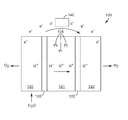
도 1은 본 명세서에 기재된 예시적인 물 전해 장치의 개략도이다.
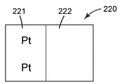
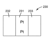
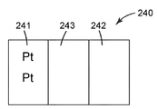
도 2a 내지 도 2d는 본 명세서에 기재된 다양한 예시적인 막 구성의 측면도이다.1 is a schematic diagram of an exemplary water electrolysis device described herein.
2A-2D are side views of various exemplary membrane configurations described herein.
단일 전지 물 전해 장치가 알려져 있지만, 물 전해 장치는 전형적으로 복수의(예를 들어, 적어도 2개의) 전지를 포함하며, 이들 전지는 다시 막, 캐소드 및 애노드를 포함한다. 도 1을 참조하면, 예시적인 물 전해 장치 전지(100)는 막(101), 캐소드(120), 및 애노드(130)를 포함한다. 막(100)은 금속 Pt 또는 Pt 산화물 중 적어도 하나의 형태의 지지된 백금(105)을 포함한다. 도시된 바와 같이, 전지(100)는 또한 애노드(130)에 인접한 선택적인 제1 유체 수송 층(FTL)(135), 및 캐소드(120)에 인접하게 위치된 선택적인 제2 유체 수송 층(125)을 포함한다. FTL(125, 135)은 확산체/집전체(DCC) 또는 가스 확산 층(GDL)으로 지칭될 수 있다. 작동 시에, 물이 제1 유체 수송 층(135)을 통과하여 애노드(130)로 전달되어, 전지(100)의 애노드 부분으로 도입된다. 전원(140)은 전지(100)에 전류원을 인가한다.Although single cell water electrolysis devices are known, water electrolysis devices typically comprise a plurality of (eg, at least two) cells, which in turn comprise a membrane, a cathode and an anode. Referring to FIG. 1, an exemplary water
일부 실시 형태에서, 막(101)은 양성자 교환 막(PEM)으로서, 이것은 우선적으로 수소 이온(용매화된 양성자)이 막을 통해 전지의 캐소드 부분으로 전달될 수 있게 하여, 막을 통해 전류를 전도될 수 있게 한다. 전자는 통상 막을 통과할 수 없고, 대신에, 전류의 형태로 외부 전기 회로를 통해 흐른다.In some embodiments,
수소 이온(H+)은 캐소드(120)에서 전자와 결합하여 수소 가스를 형성하고, 캐소드(120)에 인접하게 위치된 제2 유체 수송 층(125)을 통해 수소 가스가 수집된다. 애노드(130)에 인접하게 위치된 제1 유체 수송 층(135)을 통해 전지(100)의 애노드에서 산소 가스가 수집된다.Hydrogen ions (H + ) combine with electrons at the
가스 확산 층(GDL)(135)은 각각 애노드로의 그리고 애노드로부터의 물 및 산소 가스 수송, 및 (용매화된 양성자를 사용하여 PEM 막을 통해 전기삼투압으로 운반된) 물 및 수소 이온(H+)의 애노드로부터의 막을 통한 캐소드로의 수송을 용이하게 하여, 전류를 전도한다. 또한, 생성된 수소 가스 중 일부는 확산에 의해 캐소드로부터 막을 통해 애노드로 수송되어, 바람직하지 않은 "수소 크로스오버"를 야기한다. GDL(125, 135)은 다공성이면서 전기 전도성이며, 캐소드 측에서는 전형적으로 탄소 섬유로 구성된다. 그러나, 애노드의 고전위에서의 탄소의 분해를 피하기 위해, 애노드 상에서는 GDL로서 더 내부식성인 재료, 예를 들어 다공성 티타늄을 사용하는 것이 바람직하다. GDL은 또한 유체 수송 층(FTL) 또는 확산체/집전체(DCC)라 불릴 수 있다. 일부 실시 형태에서, 애노드 및 캐소드 층이 GDL에 적용되고, 생성되는 촉매-코팅된 GDL(CCB(촉매 코팅 배킹)로도 불림)에 PEM과 같은 중합체 전해질이 개재되어 5층 MEA를 형성한다. 그러한 5층 MEA의 5개의 층은, 순서대로: 애노드 GDL, 애노드 층, 이온 전도성 막, 캐소드 층, 및 캐소드 GDL이다. 애노드 층 및 캐소드 층은 전형적으로 각각 애노드 촉매 및 캐소드 촉매를 포함한다. 다른 실시 형태에서, 애노드 및 캐소드 층이 이온 전도성 막의 양쪽에 적용되고, 생성되는 촉매-코팅된 막(CCM)이 2개의 GDL들(또는 FTL들) 사이에 개재되어 5층 MEA를 형성한다.The gas diffusion layer (GDL) 135 is responsible for transporting water and oxygen gas to and from the anode, respectively, and water and hydrogen ions (H + ) transported by electroosmotic pressure through the PEM membrane using solvated protons. Facilitates transport from the anode of the anode through the membrane to the cathode, conducting current. In addition, some of the generated hydrogen gas is transported from the cathode through the membrane to the anode by diffusion, causing undesirable "hydrogen crossover".
본 명세서에 기재된 CCM 또는 MEA에 사용되는 이온 전도성 막은 임의의 적합한 중합체 전해질을 포함할 수 있다. 예시적인 중합체 전해질은 전형적으로 공통의 골격에 결합된 음이온성 작용기들을 가지며, 이는 전형적으로 설폰산 기이지만, 카르복실산 기, 이미드 기, 이미드산 기, 아미드 기, 또는 다른 산성 작용기를 또한 포함할 수 있다. 공통의 골격에 결합된 양이온성 작용기들을 포함하는 음이온 전도성 막이 또한 가능하지만 덜 일반적으로 사용된다. 예시적인 중합체 전해질은 전형적으로 고도로 플루오르화되며, 가장 전형적으로는 퍼플루오르화된다(예를 들어, 퍼플루오로설폰산 및 퍼플루오로설폰이미드산 중 적어도 하나). 예시적인 전해질에는 테트라플루오로에틸렌과 적어도 하나의 플루오르화된 산-작용성 공단량체의 공중합체가 포함된다. 전형적인 중합체 전해질에는 미국 델라웨어주 윌밍턴 소재의 듀폰 케미칼스(DuPont Chemicals)로부터 상표명 "나피온"(Nafion)으로; 벨기에 브뤼셀 소재의 솔베이(Solvay)로부터 상표명 "아퀴비온"(Aquivion)으로; 그리고 일본 도쿄 소재의 아사히 글래스 컴퍼니 리미티드(Asahi Glass Co. Ltd.)로부터 상표명 "플레미온"(Flemion)으로 입수가능한 것들이 포함된다. 중합체 전해질은, 그 개시내용이 본 명세서에 참고로 포함된, 미국 특허 제6,624,328호(게라(Guerra)), 및 제7,348,088호(햄록(Hamrock) 등), 및 미국 특허 출원 공개 제2004/0116742호(게라)에 기재된, 테트라플루오로에틸렌(TFE)과 FSO2-CF2CF2CF2CF2-O-CF=CF2의 공중합체일 수 있다. 중합체는 전형적으로 최대 1200(일부 실시 형태에서, 최대 1100, 1000, 900, 825, 800, 725, 또는 심지어 최대 625)의 당량(EW)을 갖는다.Ion conductive membranes used in the CCM or MEA described herein can include any suitable polymer electrolyte. Exemplary polymer electrolytes typically have anionic functional groups bonded to a common backbone, which are typically sulfonic acid groups, but also include carboxylic acid groups, imide groups, imide acid groups, amide groups, or other acidic functional groups. can do. Anionic conductive membranes comprising cationic functional groups bonded to a common backbone are also possible but less commonly used. Exemplary polymer electrolytes are typically highly fluorinated and most typically perfluorinated (eg, at least one of perfluorosulfonic acid and perfluorosulfonimide acid). Exemplary electrolytes include copolymers of tetrafluoroethylene with at least one fluorinated acid-functional comonomer. Typical polymer electrolytes include DuPont Chemicals, Wilmington, DE, under the trade name “Nafion”; From Solvay, Brussels, Belgium under the trade name “Aquivion”; And those available under the trade name "Flemion" from Asahi Glass Co. Ltd., Tokyo, Japan. Polymer electrolytes include US Pat. Nos. 6,624,328 (Guerra) and 7,348,088 (Hamrock et al.), And US Patent Application Publication No. 2004/0116742, the disclosures of which are incorporated herein by reference. It may be a copolymer of tetrafluoroethylene (TFE) and FSO 2 -CF 2 CF 2 CF 2 CF 2 -O-CF = CF 2 described in (Gera). The polymer typically has an equivalent weight (EW) of up to 1200 (in some embodiments, up to 1100, 1000, 900, 825, 800, 725, or even up to 625).
중합체는 임의의 적합한 방법에 의해서 막으로 형성될 수 있다. 중합체는 전형적으로 현탁액으로부터 캐스팅된다. 바(bar) 코팅, 분무 코팅, 슬릿 코팅, 및 브러시 코팅을 포함하는 임의의 적합한 캐스팅 방법이 사용될 수 있다. 대안적으로, 막은 압출과 같은 용융 공정에서 니트(neat) 중합체로부터 형성될 수 있다. 형성 후에, 막은, 전형적으로 적어도 120℃(일부 실시 형태에서, 적어도 130℃, 150℃, 또는 그 이상)의 온도에서 어닐링될 수 있다. 막은 전형적으로 두께가 최대 250 마이크로미터(일부 실시 형태에서, 최대 225 마이크로미터, 200 마이크로미터, 175 마이크로미터, 150 마이크로미터, 100 마이크로미터, 또는 심지어 최대 50 마이크로미터)이다.The polymer may be formed into a film by any suitable method. The polymer is typically cast from suspension. Any suitable casting method can be used, including bar coating, spray coating, slit coating, and brush coating. Alternatively, the membrane may be formed from neat polymer in a melting process such as extrusion. After formation, the membrane may typically be annealed at a temperature of at least 120 ° C. (in some embodiments, at least 130 ° C., 150 ° C., or more). The membrane is typically up to 250 micrometers thick (in some embodiments, up to 225 micrometers, 200 micrometers, 175 micrometers, 150 micrometers, 100 micrometers, or even up to 50 micrometers).
중합체 막은 상호연결된 섬유들의 다공성 네트워크로 이루어진 지지 매트릭스를 또한 포함할 수 있는데, 이는 수소 발생 동안의 캐소드 측의 고압으로 인한, 막을 가로지르는 때때로의 큰 압력차를 견디도록 이온 교환 중합체(이오노머)에 추가적인 기계적 강도를 제공할 것이다. 지지 매트릭스는 팽창된 폴리테트라플루오로에틸렌(예를 들어, 미국 델라웨어주 윌밍턴 소재의 듀폰 케미칼스로부터 상표명 "테플론"(TEFLON)으로 입수가능함), 또는 이오노머의 산성 환경에서 안정한, 부분적으로 플루오르화된 섬유질 매트릭스로 제조될 수 있다.The polymer membrane may also comprise a support matrix consisting of a porous network of interconnected fibers, which is in addition to the ion exchange polymer (ionomer) to withstand the occasional large pressure differential across the membrane due to the high pressure on the cathode side during hydrogen evolution. Will provide mechanical strength. The support matrix is expanded polytetrafluoroethylene (for example, available under the trade designation “Teflon” (TEFLON) from DuPont Chemicals, Wilmington, DE), or partially fluorine, which is stable in the acidic environment of the ionomer. It can be made into a ized fibrous matrix.
일부 실시 형태에서, 막은 나노섬유 매트로 보강된 제1 양성자 전도성 중합체를 갖고; 나노섬유 매트는 중합체 및 중합체 블렌드로부터 선택되는 섬유 재료를 포함하는 나노섬유로 제조되고; 섬유 재료는 섬유 재료 양성자 전도율을 갖고; 제1 양성자 전도성 중합체는 제1 양성자 전도성 중합체 전도율을 갖고; 섬유 재료 양성자 전도율은 제1 양성자 전도성 중합체 전도율보다 작다.In some embodiments, the membrane has a first proton conductive polymer reinforced with a nanofiber mat; Nanofiber mats are made of nanofibers comprising a fiber material selected from polymers and polymer blends; The fiber material has a fiber material proton conductivity; The first proton conductive polymer has a first proton conductive polymer conductivity; The fibrous material proton conductivity is less than the first proton conductive polymer conductivity.
일부 실시 형태에서, 막 내의 섬유 재료는 고도로 플루오르화된 중합체, 퍼플루오르화된 중합체, 탄화수소 중합체, 또는 이들의 블렌드 및 조합을 포함할 수 있다. 일부 실시 형태에서, 막 내의 섬유 재료는 전기방사에 적합한 중합체를 포함할 수 있으며, 이는 폴리비닐리덴 플루오라이드(PVDF), 폴리설폰(PSU), 폴리(에테르설폰)(PES), 폴리에틸렌이민(PEI), 폴리벤즈이미다졸(PBI), 폴리페닐렌 옥사이드(PPO), 폴리에테르 에테르 케톤(PEEK), 폴리페닐 에테르(PPE), 폴리페닐렌 에테르 설폰(PPES), 폴리에테르 케톤(PEK), 이들의 블렌드 및 조합으로 이루어진 군으로부터 선택된다. 일부 실시 형태에서, 막 내의 섬유 재료는 전기방사된 나노섬유일 수 있다.In some embodiments, the fibrous material in the membrane can include highly fluorinated polymers, perfluorinated polymers, hydrocarbon polymers, or blends and combinations thereof. In some embodiments, the fiber material in the membrane may comprise a polymer suitable for electrospinning, which may be polyvinylidene fluoride (PVDF), polysulfone (PSU), poly (ethersulfone) (PES), polyethyleneimine (PEI) ), Polybenzimidazole (PBI), polyphenylene oxide (PPO), polyether ether ketone (PEEK), polyphenyl ether (PPE), polyphenylene ether sulfone (PPES), polyether ketone (PEK), these Blends and combinations thereof. In some embodiments, the fiber material in the membrane can be electrospun nanofibers.
전형적으로, 막에는 어떠한 Ce 또는 Mn이 없는 것이 바람직하다(즉, 각각 원소 Ce 및 Mn으로서 계산된, 0.001 mg/㎤ 이하의 Ce 또는 MN).Typically, the film is preferably free of any Ce or Mn (ie, Ce or MN up to 0.001 mg / cm 3, calculated as the elements Ce and Mn, respectively).
예시적인 막에 대한 추가적인 상세 사항은, 예를 들어 미국 특허 출원 공개 제2008/0113242호, 제2002/0100725호, 및 제2011/036935호에서 찾아볼 수 있으며, 이들의 개시내용은 본 명세서에 참고로 포함된다.Further details on exemplary membranes can be found, for example, in US Patent Application Publication Nos. 2008/0113242, 2002/0100725, and 2011/036935, the disclosures of which are incorporated herein by reference. Included as.
선택적으로, 막은 촉매(촉매-보유 나노구조화된 위스커를 포함함)의 침착 또는 적층 전에 양이온 불순물을 제거하기 위해 산으로 세척된다(예를 들어, 임의의 금속 양이온 불순물을 제거하기 위해 1.0 몰 질산으로 세척되거나, 또는 금속 양이온 불순물 및 유기 불순물을 제거하기 위해 질산 + 과산화수소로 세척된 후에, 탈이온수로 헹궈진다). 세척조를 (예를 들어, 30℃, 40℃, 50℃, 60℃, 70℃, 또는 심지어 80℃로) 가열함으로써 세정을 더 신속하게 할 수 있다. 막의 산 세척의 이점은 특정 막에 따라 좌우될 수 있다.Optionally, the membrane is washed with acid to remove cationic impurities prior to deposition or deposition of catalyst (including catalyst-bearing nanostructured whiskers) (e.g., 1.0 mole nitric acid to remove any metal cationic impurities). Or rinsed with deionized water after being washed with nitric acid + hydrogen peroxide to remove metal cation impurities and organic impurities). The cleaning can be made faster by heating the wash bath (eg to 30 ° C, 40 ° C, 50 ° C, 60 ° C, 70 ° C, or even 80 ° C). The benefits of acid washing of the membrane may depend on the particular membrane.
MEA를 제조하는 데 있어서, GDL이 CCM의 양쪽에 적용될 수 있다. GDL은 임의의 적합한 수단에 의해 적용될 수 있다. 적합한 GDL에는 사용되는 전극 전위에서 안정한 것들이 포함된다. 예를 들어, 캐소드 GDL은 적절한 수소 발생에 충분한 낮은 전위에서 작동되기 때문에 미립자 카본 블랙 또는 탄소 섬유를 함유할 수 있는 반면, 애노드 GDL은 전형적으로 Ti 또는 산소 발생의 고전위 특성에서 안정한 일부 다른 재료로 제조된다. 전형적으로, 캐소드 GDL은 직조 또는 부직 탄소 섬유의 탄소 섬유 구조물이다. 예시적인 탄소 섬유 구조물에는, 예를 들어, 일본 소재의 토레이(Toray)로부터의 상표명 "토레이"(TORAY)(카본지); 미국 매사추세츠주 로렌스 소재의 스펙트라카브(Spectracarb)로부터의 "스펙트라카브"(SPECTRACARB)(카본지); 및 미국 미주리주 세인트루이스 소재의 졸텍(Zoltek)으로부터의 "졸텍"(탄소 천(carbon cloth))뿐만 아니라, 일본 소재의 미츠비시 레이온 컴퍼니(Mitsubishi Rayon Co.) 및 독일 소재의 프로이덴베르크(Freudenberg)로부터 입수가능한 것들이 포함된다. GDL은 탄소 입자 코팅, 친수화 처리, 및 폴리테트라플루오로에틸렌(PTFE)에 의한 코팅과 같은 소수화 처리를 비롯하여, 각종 재료로 코팅될 수 있거나 함침될 수 있다.In manufacturing the MEA, GDL can be applied to both sides of the CCM. GDL may be applied by any suitable means. Suitable GDLs include those that are stable at the electrode potentials used. For example, cathode GDL may contain particulate carbon black or carbon fiber because it operates at a low potential sufficient for proper hydrogen evolution, while anode GDL is typically made of Ti or some other material that is stable in the high potential properties of oxygen evolution. Are manufactured. Typically, the cathode GDL is a carbon fiber structure of woven or nonwoven carbon fibers. Exemplary carbon fiber structures include, for example, the trade name " TORAY " (carbon paper) from Toray, Japan; "SPECTRACARB" (Carbon Paper) from Spectracarb, Lawrence, Mass., USA; And "Zoltek" (carbon cloth) from Zoltek, St. Louis, Missouri, as well as Mitsubishi Rayon Co., Japan, and Freudenberg, Germany. Available ones are included. GDL may be coated or impregnated with various materials, including carbon particle coating, hydrophilization treatment, and hydrophobization treatment such as coating with polytetrafluoroethylene (PTFE).
전형적으로, 전해 장치 애노드 GDL은, 예를 들어, Pt, Ti, Ta, Nb, Zr, Hf, 또는 부식되지 않을 금속 합금(예를 들어, Ti-10V-5Zr)으로 구성된, 금속 폼(foam) 또는 다공성 금속 스크린 또는 메시이지만, 1.23 V의 물 산화를 위한 열역학적 전위를 초과하는 사용 전위에서의 전해 장치 작동을 위해 (예를 들어, Ti GDL의 경우에 표면 상에 Pt의 층을 스퍼터링 침착 또는 전기 도금함으로써) 적절한 전기 전도율을 가질 것이다.Typically, the electrolytic device anode GDL is composed of a metal foam, for example composed of Pt, Ti, Ta, Nb, Zr, Hf, or a metal alloy that will not corrode (eg Ti-10V-5Zr). Or for sputter depositing or electrospraying a layer of Pt on a surface for a electrolytic device at a use potential that exceeds a thermodynamic potential for water oxidation of 1.23 V, for example a porous metal screen or mesh. By plating) will have a suitable electrical conductivity.
사용 중에, 본 명세서에 기재된 MEA는 전형적으로, 분배판(distribution plate)으로 알려져 있으며 종판(end plate)(또는 멀티-셀 스택(multi-cell stack)의 경우에, 분리판(bipolar plate; BPP))으로도 알려져 있는 2개의 강성(rigid) 판들 사이에 개재된다. GDL과 마찬가지로, 분배판은 전기 전도성이며, 맞닿아 배치된 전극 GDL의 전위에서 안정하여야 한다. 분배판은 전형적으로 탄소 복합재, 금속, 또는 코팅되거나 도금된 금속과 같은 재료로 제조된다. GDL에 대하여, 전해 장치의 캐소드 판은 연료 전지에 사용하기에 일반적인 임의의 재료일 수 있지만, 전해 장치의 애노드 판은 가역적 수소 전극(reversible hydrogen electrode; RHE)의 전위에 비해 1.23 볼트의 전위 초과에서(일부 실시 형태에서, 최대 1.5 볼트, 2.5 볼트, 또는 심지어 그 이상에서) 부식되지 않을 재료로 제조되어야 한다. 애노드 판을 위한 예시적인 코팅은 Ti-10V-5Zr을 포함한다. 분배판은, 전형적으로는 MEA(들)와 대면하는 표면(들)에 각인되거나 밀링되거나 성형되거나 스탬핑된 적어도 하나의 유체-전도성 채널을 통하여, MEA 전극 표면으로 그리고 MEA 전극 표면으로부터 반응물 유체 또는 생성물 유체를 분배한다. 이들 채널은 때때로 유동장(flow field)이라 불린다. 분배판은 한 스택 내의 2개의 연속된 MEA로 그리고 그로부터 유체를 분배할 수 있는데, 하나의 면은 제1 MEA의 애노드로 물을 안내하고 그로부터 산소를 안내하는 반면, 다른 면은 (막을 가로지르는) 발생된 수소 및 물을 다음 MEA의 캐소드로부터 멀리 안내한다. 대안적으로, 분배판은 오직 하나의 면 상에 채널을 가져서, 오직 그 면 상에서 MEA로 또는 MEA로부터 유체를 분배할 수 있으며, 이 경우에, 분배판은 "종판"으로 지칭될 수 있다.In use, the MEA described herein is typically known as a distribution plate and in the case of an end plate (or multi-cell stack, a bipolar plate (BPP)). It is sandwiched between two rigid plates, also known as). Like the GDL, the distribution plate is electrically conductive and must be stable at the potential of the abutting electrode GDL. Distribution plates are typically made of a material such as carbon composite, metal, or coated or plated metal. For GDL, the cathode plate of the electrolytic device may be any material common for use in fuel cells, but the anode plate of the electrolytic device is above a potential of 1.23 volts relative to the potential of a reversible hydrogen electrode (RHE). It should be made of a material that will not corrode (in some embodiments, up to 1.5 volts, 2.5 volts, or even more). Exemplary coatings for the anode plate include Ti-10V-5Zr. The distribution plate is typically a reactant fluid or product through the at least one fluid-conducting channel stamped, milled, shaped or stamped on the surface (s) facing the MEA (s), to and from the MEA electrode surface. Dispense the fluid. These channels are sometimes called flow fields. The distribution plate can distribute fluid to and from two successive MEAs in one stack, with one side guiding water to and from the anode of the first MEA, while the other side (crossing the membrane) The generated hydrogen and water are guided away from the cathode of the next MEA. Alternatively, the distribution plate may have a channel on only one side, so as to dispense fluid to or from the MEA only on that side, in which case the distribution plate may be referred to as an "end plate".
막 내의 금속 Pt 또는 Pt 산화물 중 적어도 하나의 적어도 일부분은 지지체(예를 들어, 탄소 지지체) 상에 존재한다. 지지된 Pt는 당업계에 알려진 기법을 사용하여 막으로 혼입될 수 있으며, 이에는 탈이온수로 사전습윤된 탄소 지지된 Pt를 이오노머의 액체 현탁액에 첨가한 후, 생성된 혼합물로부터 막을 캐스팅함으로써 행해질 수 있는 기법이 포함된다. 탄소 지지체는 탄소 구체 또는 탄소 입자(일부 실시 형태에서, 1:1 내지 2:1, 또는 심지어 1:1 내지 5:1 범위의 종횡비를 가짐) 중 적어도 하나를 포함한다. 예시적인 탄소 구체는, 예를 들어 미국 매사추세츠주 빌레리카 소재의 카보트 코포레이션(Cabot Corporation)으로부터 상표명 "벌칸(VULCAN) XC72" 및 "블랙 펄(BLACK PEARLS) BP2000"으로 입수가능하다. Pt 촉매로 이미 코팅된 예시적인 탄소 지지체는, 예를 들어 일본 가나가와 히라츠카 소재의 다나카 기킨조쿠 고교 케이. 케이.(Tanaka Kikinzoku Kogyo K. K.)로부터 상표명"TEC10F50E", "TEC10BA50E", "TEC10EA50E", "TEC10VA50E", "TEC10EA20E-HT", 및 "TEC10VA20E"로 입수가능하다.At least a portion of at least one of the metal Pt or Pt oxide in the film is present on a support (eg, a carbon support). Supported Pt can be incorporated into the membrane using techniques known in the art, which can be done by adding pre-wetted carbon supported Pt to deionized water to the liquid suspension of the ionomer and then casting the membrane from the resulting mixture. Techniques are included. The carbon support comprises at least one of carbon spheres or carbon particles (in some embodiments, having aspect ratios ranging from 1: 1 to 2: 1, or even 1: 1 to 5: 1). Exemplary carbon spheres are available, for example, under the trade names "VULCAN XC72" and "BLACK PEARLS BP2000" from Cabot Corporation, Billerica, Massachusetts. Exemplary carbon supports already coated with a Pt catalyst include, for example, Tanaka Kikinjoku Kogyo K., Hiratsuka, Kanagawa, Japan. Available under the trade names "TEC10F50E", "TEC10BA50E", "TEC10EA50E", "TEC10VA50E", "TEC10EA20E-HT", and "TEC10VA20E" from Tanaka Kikinzoku Kogyo K.K.
탄소 지지체는 또한 탄소 나노튜브(예를 들어, 단일벽 탄소 나노튜브(SWNT)(때때로 "버키튜브"로 지칭됨), 이중벽 탄소 나노튜브(DWNT), 또는 다중벽 탄소 나노튜브(MWNT)) 중 적어도 하나를 포함한다. 탄소 나노튜브는, 예를 들어, 미국 사우스캐롤라이나주 리지빌 소재의 쇼와 덴코 카본 세일즈, 인코포레이티드(Showa Denko Carbon Sales, Inc.)로부터 상표명 "VGCF-H"로 입수가능하다.The carbon support may also be in carbon nanotubes (eg, single-walled carbon nanotubes (SWNTs) (sometimes referred to as "buckytubes"), double-walled carbon nanotubes (DWNTs), or multi-walled carbon nanotubes (MWNTs). At least one. Carbon nanotubes are available, for example, under the trade name "VGCF-H" from Showa Denko Carbon Sales, Inc., Ridgeville, SC.
탄소 지지체는 탄소 풀러렌(때때로 "버키볼"로 지칭됨)을 포함한다. 탄소 풀러렌은, 예를 들어 일본 도쿄 치요다구 소재의 프론티어 카본 코포레이션(Frontier Carbon Corporation)으로부터 상표명 "나놈"(NANOM)으로 입수가능하다.The carbon support includes carbon fullerenes (sometimes referred to as "buckyballs"). Carbon fullerene is available, for example, under the trade name "NANOM" from Frontier Carbon Corporation of Chiyoda-ku, Tokyo, Japan.
탄소 지지체는 탄소 나노섬유 또는 탄소 마이크로섬유 중 적어도 하나를 포함한다. 탄소 나노섬유 및 탄소 마이크로섬유는, 예를 들어 미국 오하이오주 시더빌 소재의 파이로그라프 프로덕츠, 인코포레이티드(Pyrograf Products, Inc.)로부터 상표명 "파이로그라프-III"(PYROGRAF-III)로 입수가능하다.The carbon support comprises at least one of carbon nanofibers or carbon microfibers. Carbon nanofibers and carbon microfibers are, for example, manufactured under the trade designation "PYROGRAF-III" from Pyrograf Products, Inc., Cedarville, Ohio. Available.
일부 실시 형태에서, 지지체는 나노구조화된 위스커(예를 들어, 페릴렌 레드 위스커)를 포함한다. 나노구조화된 위스커는 미국 특허 제4,812,352호(데브(Debe)), 제5,039,561호(데브), 제5,338,430호(파스니지(Parsonage) 등), 제6,136,412호(스파이웍(Spiewak) 등), 및 제7,419,741호(번스트롬(Vernstrom) 등)에 기재된 것들을 포함하는, 당업계에 공지된 기법들에 의해 제공될 수 있으며, 이들의 개시내용은 본 명세서에 참고로 포함된다. 일반적으로, 나노구조화된 위스커는, 예를 들어, 기재(substrate)(예를 들어, 미세구조화된 촉매 전사 중합체) 상에 페릴렌 레드와 같은 유기 또는 무기 재료의 층을 진공 침착하고(예를 들어, 승화시키고), 이어서 열적 어닐링에 의해 페릴렌 레드 안료를 나노구조화된 위스커로 전환시킴으로써 제공될 수 있다. 전형적으로, 진공 침착 단계는 약 10-3 토르 또는 0.1 파스칼 이하의 총 압력에서 수행된다. 예시적인 미세구조는 유기 염료 "페릴렌 레드", 씨.아이. 피그먼트 레드(C.I. Pigment Red) 149(즉, N,N'-다이(3,5-자일릴)페릴렌-3,4:9,10-비스(다이카르복스이미드))의 열 승화 및 진공 어닐링에 의해 제조된다. 나노구조화된 유기 층을 제조하기 위한 방법이, 예를 들어 문헌[Materials Science and Engineering, A158 (1992), pp. 1-6]; 문헌[J. Vac. Sci. Technol. A, 5 (4), July/August, 1987, pp. 1914-16]; 문헌[J. Vac. Sci. Technol. A, 6, (3), May/August, 1988, pp. 1907-11]; 문헌[Thin Solid Films, 186, 1990, pp. 327-47]; 문헌[J. Mat. Sci., 25, 1990, pp. 5257-68]; 문헌[Rapidly Quenched Metals, Proc. of the Fifth Int. Conf. on Rapidly Quenched Metals, Wurzburg, Germany (Sep. 3-7, 1984), S. Steeb et al., eds., Elsevier Science Publishers B.V., New York, (1985), pp. 1117-24]; 문헌[Photo. Sci. and Eng., 24, (4), July/August, 1980, pp. 211-16]; 및 미국 특허 제4,340,276호(마피트(Maffitt) 등) 및 제4,568,598호(빌카디(Bilkadi) 등)에 개시되어 있으며, 이들의 개시내용은 본 명세서에 참고로 포함된다. 탄소 나노튜브 어레이를 사용하는 촉매 층의 특성이 논문["High Dispersion and Electrocatalytic Properties of Platinum on Well-Aligned Carbon Nanotube Arrays," Carbon, 42, (2004), 191-197]에 개시되어 있다. 풀 또는 강모 형태의 규소(grassy or bristled silicon)를 사용하는 촉매 층의 특성이 미국 특허 출원 공개 제2004/0048466 A1호(고어(Gore) 등)에 개시되어 있다.In some embodiments, the support comprises nanostructured whiskers (eg, perylene red whiskers). Nanostructured whiskers are described in US Pat. Nos. 4,812,352 (Debe), 5,039,561 (Dev), 5,338,430 (Parsonage, et al.), 6,136,412 (Spiewak et al.), And And may be provided by techniques known in the art, including those described in 7,419,741 (Vernstrom et al.), The disclosures of which are incorporated herein by reference. Generally, nanostructured whiskers, for example, vacuum deposit a layer of organic or inorganic material, such as perylene red, onto a substrate (eg, a microstructured catalytic transfer polymer) (eg, , Sublimation), and then by converting the perylene red pigment into a nanostructured whisker by thermal annealing. Typically, the vacuum deposition step is performed at a total pressure of about 10 −3 Torr or 0.1 Pascal or less. Exemplary microstructures include the organic dye "Perylene Red", C. I. Thermal Sublimation and Vacuum of CI Pigment Red 149 (ie, N, N'-di (3,5-xylyl) perylene-3,4: 9,10-bis (dicarboximide)) It is prepared by annealing. Methods for making nanostructured organic layers are described, for example, in Materials Science and Engineering, A158 (1992), pp. 1-6]; J. Vac. Sci. Technol. A, 5 (4), July / August, 1987, pp. 1914-16; J. Vac. Sci. Technol. A, 6, (3), May / August, 1988, pp. 1907-11; Thin Solid Films, 186, 1990, pp. 327-47; J. Mat. Sci., 25, 1990, pp. 5257-68; Rapidly Quenched Metals, Proc. of the Fifth Int. Conf. on Rapidly Quenched Metals, Wurzburg, Germany (Sep. 3-7, 1984), S. Steeb et al., eds., Elsevier Science Publishers BV, New York, (1985), pp. 1117-24; Photo. Sci. and Eng., 24, (4), July / August, 1980, pp. 211-16; And US Pat. Nos. 4,340,276 (Maffitt et al.) And 4,568,598 (Bilkadi et al.), The disclosures of which are incorporated herein by reference. The characteristics of the catalyst layer using carbon nanotube arrays are described in the article "High Dispersion and Electrocatalytic Properties of Platinum on Well-Aligned Carbon Nanotube Arrays," Carbon, 42, (2004), 191-197. The properties of catalyst layers using grassy or bristled silicon in grass or bristles form are disclosed in US Patent Application Publication No. 2004/0048466 A1 (Gore et al.).
진공 침착은 임의의 적합한 장치에서 수행될 수 있다(예를 들어, 미국 특허 제5,338,430호(파스니지 등), 제5,879,827호(데브 등), 제5,879,828호(데브 등), 제6,040,077호(데브 등), 및 제6,319,293호(데브 등), 및 미국 특허 출원 공개 제2002/0004453 A1호(호겐(Haugen) 등)를 참조하며, 이들의 개시내용은 본 명세서에 참고로 포함된다). 한 가지 예시적인 장치가 미국 특허 제5,338,430호(파스니지 등)의 도 4a에 개략적으로 도시되고, 첨부된 본문에 논의되어 있는데, 기재를 드럼 상에 장착하고, 이어서 유기 전구체(예를 들어, 페릴렌 레드 안료)를 침착하기 위한 승화 또는 증발 공급원 위에서 드럼을 회전시켜, 나노구조화된 위스커를 형성한다.Vacuum deposition may be performed in any suitable apparatus (eg, US Pat. Nos. 5,338,430 (Pasage et al.), 5,879,827 (Dev et al.), 5,879,828 (Dev et al.), 6,040,077 (Dev et al.) ) And 6,319,293 (Dev et al.), And US Patent Application Publication No. 2002/0004453 A1 (Haugen et al.), The disclosures of which are incorporated herein by reference). One exemplary apparatus is schematically illustrated in FIG. 4A of US Pat. No. 5,338,430 (Pasage et al.) And discussed in the accompanying text, in which a substrate is mounted on a drum, followed by an organic precursor (eg, The drum is rotated over a sublimation or evaporation source to deposit the rylene red pigment) to form a nanostructured whisker.
전형적으로, 침착되는 페릴렌 레드 안료의 공칭 두께는 약 50 nm 내지 500 nm의 범위이다. 전형적으로, 위스커는 평균 단면 치수가 20 nm 내지 60 nm의 범위이고 평균 길이가 0.3 마이크로미터 내지 3 마이크로미터의 범위이다.Typically, the nominal thickness of the perylene red pigment deposited is in the range of about 50 nm to 500 nm. Typically, whiskers have an average cross-sectional dimension in the range of 20 nm to 60 nm and an average length in the range of 0.3 micrometers to 3 micrometers.
일부 실시 형태에서, 위스커는 배킹(backing)에 부착된다. 예시적인 배킹은 폴리이미드, 나일론, 금속 포일, 또는 최대 300℃의 열적 어닐링 온도를 견딜 수 있는 기타 재료를 포함한다. 일부 실시 형태에서, 배킹은 평균 두께가 25 마이크로미터 내지 125 마이크로미터의 범위이다.In some embodiments, the whisker is attached to the backing. Exemplary backings include polyimide, nylon, metal foils, or other materials capable of withstanding thermal annealing temperatures up to 300 ° C. In some embodiments, the backing has an average thickness in the range of 25 micrometers to 125 micrometers.
일부 실시 형태에서, 배킹은 그의 표면들 중 적어도 하나 상에 미세구조를 갖는다. 일부 실시 형태에서, 미세구조는 나노구조화된 위스커의 평균 크기의 적어도 3배(일부 실시 형태에서, 적어도 4, 5, 10배 또는 그 이상)인 실질적으로 균일하게 형상화되고 크기 설정된 특징부로 구성된다. 미세구조의 형상은, 예를 들어, V형 홈 및 피크(예를 들어, 미국 특허 제6,136,412호(스파이웍 등)를 참조하며, 이의 개시내용은 본 명세서에 참고로 포함됨) 또는 피라미드(예를 들어, 미국 특허 제7,901,829호(데브 등)를 참조하며, 이의 개시내용은 본 명세서에 참고로 포함됨)일 수 있다. 일부 실시 형태에서, 미세구조의 특징부들의 일부 분율은 미세구조화된 피크들의 평균 또는 대다수 위로 주기적인 방식으로 연장되며, 예를 들어 매 31번째 V-홈 피크는 그의 양쪽에 있는 것들보다 25% 또는 50% 또는 심지어 100% 더 높다. 일부 실시 형태에서, 미세구조화된 피크들의 대다수 위로 연장되는 특징부들의 이러한 분율은 최대 10%(일부 실시 형태에서 최대 3%, 2%, 또는 심지어 최대 1%)일 수 있다. 가끔 더 큰 미세구조 특징부의 사용은 롤-투-롤(roll-to-roll) 코팅 작동에서 코팅된 기재가 롤러의 표면 위로 이동할 때 균일하게 더 작은 미세구조 피크를 보호하는 것을 용이하게 할 수 있다. 더 작은 미세구조의 피크가 아니라 가끔의 더 큰 특징부가 롤러의 표면에 닿으므로, 기재가 코팅 공정을 통해 이동함에 따라 긁히거나 또는 달리 방해받기 쉬운 나노구조화된 재료 또는 위스커가 훨씬 더 적다. 일부 실시 형태에서, 나노구조화된 위스커는 이온 전도성 막 내에 적어도 부분적으로 매립된다. 일부 실시 형태에서, 미세구조 특징부는 막 전극 조립체(membrane electrode assembly; MEA)를 제조하는 데 있어서 촉매가 전사될 막의 두께의 절반보다 실질적으로 더 작다. 이는 촉매 전사 공정 동안, 더 큰 미세구조 특징부가 막을 통과하여 막의 반대측 면 상의 전극과 중첩되지 않도록 하기 위한 것이다. 일부 실시 형태에서, 가장 큰 미세구조 특징부는 막 두께의 1/3 또는 1/4 미만이다. 가장 얇은 이온 교환 막(예를 들어, 두께가 약 10 내지 15 마이크로미터)의 경우, 높이가 약 3 내지 4.5 마이크로미터보다 크지 않은 미세구조화된 특징부를 갖는 기재를 갖는 것이 바람직할 수 있다. 일부 실시 형태에서, V형 또는 다른 미세구조화된 특징부의 측면의 경사도(steepness) 또는 인접한 특징부들 사이의 끼인각은, 라미네이션-전사 공정 동안 촉매 전사의 용이성을 위하여 그리고 기재 배킹의 평면 기하학적 표면에 비하여 미세구조화된 층의 2의 제곱근(1.414)의 표면적으로부터 비롯되는 전극 표면적의 증가를 갖기 위하여, 대략 90°인 것이 바람직할 수 있다.In some embodiments, the backing has a microstructure on at least one of its surfaces. In some embodiments, the microstructures consist of substantially uniformly shaped and sized features that are at least three times the mean size of the nanostructured whiskers (in some embodiments, at least 4, 5, 10 times, or more). For the shape of the microstructures, see, for example, V-shaped grooves and peaks (eg, US Pat. No. 6,136,412 (Spywork, etc.), the disclosure of which is incorporated herein by reference) or pyramids (eg, See, for example, US Pat. No. 7,901,829 to Dev et al., The disclosure of which is incorporated herein by reference. In some embodiments, some fraction of the features of the microstructure extend in a periodic manner over the average or majority of the microstructured peaks, for example every 31th V-groove peak is 25% or more than those on both sides thereof. 50% or even 100% higher. In some embodiments, this fraction of features extending over the majority of the microstructured peaks may be up to 10% (up to 3%, 2%, or even up to 1% in some embodiments). Sometimes the use of larger microstructure features may facilitate protecting even smaller microstructure peaks as the coated substrate moves over the surface of the roller in a roll-to-roll coating operation. . Since sometimes larger features, rather than smaller microstructure peaks, touch the surface of the roller, there are far fewer nanostructured materials or whiskers that are susceptible to scratching or otherwise being disturbed as the substrate moves through the coating process. In some embodiments, the nanostructured whiskers are at least partially embedded in the ion conductive membrane. In some embodiments, the microstructure features are substantially less than half the thickness of the membrane to which the catalyst is to be transferred in producing the membrane electrode assembly (MEA). This is to ensure that during the catalytic transfer process, larger microstructure features do not pass through the membrane and overlap with electrodes on the opposite side of the membrane. In some embodiments, the largest microstructure feature is less than 1/3 or 1/4 of the film thickness. For the thinnest ion exchange membranes (eg, about 10 to 15 micrometers in thickness), it may be desirable to have a substrate having microstructured features whose height is no greater than about 3 to 4.5 micrometers. In some embodiments, the steepness of the sides of the V-shaped or other microstructured features or the included angle between adjacent features is fine for ease of catalyst transfer during the lamination-transcription process and relative to the planar geometric surface of the substrate backing. It may be desirable to have approximately 90 ° to have an increase in electrode surface area resulting from the surface area of the square root of 2 (1.414) of the structured layer.
일부 실시 형태에서, 지지체는 산화주석을 포함한다. 그러한 산화주석은, 예를 들어 일본 가나가와 히라츠카 소재의 다나카 기킨조쿠 고교 케이. 케이.로부터 상표명 "TEC10(SnO2/A)10E" 및 "TEC10(SnO2/A)30E"로 입수가능한 미세하게 그라인딩된 입자 형태의 이미 촉매된 Pt/SnO2이다.In some embodiments, the support comprises tin oxide. Such tin oxide is, for example, Tanaka Kikinjoku Kogyo K. Kanagawa Hiratsuka. K. is already catalyzed Pt / SnO 2 in the form of finely ground particles available under the trade names “TEC10 (SnO 2 / A) 10E” and “TEC10 (SnO 2 / A) 30E”.
일부 실시 형태에서, 지지체는 점토를 포함한다. 이들 점토는 입자 또는 소판 형태를 취할 수 있으며, 합성 또는 자연 발생 층상 규산염일 수 있다. 그러한 점토는, 예를 들어 독일 베젤 소재의 비와이케이 애디티브즈 앤드 인스트루먼츠, 게엠베하(BYK Additives and Instruments, GmbH)로부터 상표명 "라포나이트(LAPONITE) RD"로 입수가능하다.In some embodiments, the support comprises clay. These clays may take the form of particles or platelets, and may be synthetic or naturally occurring layered silicates. Such clays are available, for example, under the trade name "LAPONITE RD" from BYK Additives and Instruments, GmbH, Bezel, Germany.
백금은, 예를 들어 미국 특허 제5,879,827호(데브 등), 제6,040,077호(데브 등), 및 제7,419,741호(번스트롬 등), 및 미국 특허 출원 공개 제2014/0246304 A1호(데브 등)에서 일반적인 교시내용을 사용하여, 지지체 상에 스퍼터링될 수 있으며, 이들의 개시내용은 본 명세서에 참고로 포함된다. 일부 실시 형태에서, 스퍼터링은 적어도 부분적으로는, 적어도 120 sccm(즉, 분당 표준 세제곱센티미터)의 유량으로 스퍼터링 챔버 내로 유입되는 아르곤을 포함하는 분위기에서 수행된다.Platinum is described, for example, in US Pat. Nos. 5,879,827 (Dev et al.), 6,040,077 (Dev et al.), And 7,419,741 (Burnstrom et al.), And US Patent Application Publication No. 2014/0246304 A1 (Dev et al.). Using the general teachings, it can be sputtered on a support, the disclosures of which are incorporated herein by reference. In some embodiments, sputtering is performed at least in part in an atmosphere that includes argon entering the sputtering chamber at a flow rate of at least 120 sccm (ie, standard cubic centimeters per minute).
일부 실시 형태에서, 금속 Pt 또는 Pt 산화물 중 적어도 하나는 총체적으로 0.05 mg/㎤ 내지 100 mg/㎤(일부 실시 형태에서, 0.1 mg/㎤ 내지 100 mg/㎤, 1 mg/㎤ 내지 75 mg/㎤, 또는 심지어 5 mg/㎤ 내지 50 mg/㎤) 범위의 농도로 막에 존재한다.In some embodiments, at least one of the metal Pt or Pt oxide is collectively 0.05 mg / cm 3 to 100 mg / cm 3 (in some embodiments, 0.1 mg / cm 3 to 100 mg / cm 3, 1 mg / cm 3 to 75 mg / cm 3) Or even at concentrations ranging from 5 mg / cm 3 to 50 mg / cm 3).
일부 실시 형태에서, 막 내의 금속 Pt 또는 Pt 산화물 중 적어도 하나는 막 전체에 걸쳐 분포된다. 일부 실시 형태에서, 상기 막은 상기 제1 주 표면과 상기 제2 주 표면 사이에서 연장되는 두께를 가지며, 상기 두께를 가로질러 동일하게 이격된 제1 영역, 제2 영역, 및 제3 영역을 가지며, 상기 제1 영역은 상기 제1 주 표면에 가장 가까운 영역이고, 상기 제2 영역은 상기 제2 주 표면에 가장 가까운 영역이고, 상기 제3 영역은 상기 제1 영역과 상기 제2 영역 사이에 위치되며, 상기 제1 영역 및 상기 제3 영역에는 각각 금속 Pt 및 Pt 산화물 둘 모두가 본질적으로 없고(즉, 원소 Pt로서 계산될 때, 0.001 mg/㎤ 이하), 상기 제2 영역은 상기 막 내의 상기 금속 Pt 또는 Pt 산화물 중 적어도 하나를 포함한다. 일부 실시 형태에서, 금속 Pt 또는 Pt 산화물 중 적어도 하나는 제2 영역 전체에 걸쳐 분포된다.In some embodiments, at least one of the metal Pt or Pt oxide in the film is distributed throughout the film. In some embodiments, the film has a thickness extending between the first major surface and the second major surface and has a first region, a second region, and a third region equally spaced across the thickness, The first region is the region closest to the first major surface, the second region is the region closest to the second major surface, and the third region is located between the first region and the second region Wherein the first region and the third region are essentially free of both metal Pt and Pt oxide (i.e., 0.001 mg / cm 3 or less, when calculated as element Pt), and the second region is the metal in the film. At least one of Pt or Pt oxide. In some embodiments, at least one of the metal Pt or Pt oxide is distributed throughout the second region.
일부 실시 형태에서, 상기 막은 상기 제1 주 표면과 상기 제2 주 표면 사이에서 연장되는 두께를 가지며, 상기 두께는 상기 제1 주 표면과 상기 제2 주 표면 사이의 중간점, 상기 제1 주 표면과 상기 중간점 사이의 제1 영역, 및 상기 제2 주 표면과 상기 중간점 사이의 제2 영역을 가지며, 상기 제1 영역은 상기 막 내의 상기 금속 Pt 또는 Pt 산화물 중 적어도 하나를 포함하고, 상기 제2 영역에는 금속 Pt 및 Pt 산화물 둘 모두가 본질적으로 없다. 일부 실시 형태에서, 금속 Pt 또는 Pt 산화물 중 적어도 하나는 제1 영역 전체에 걸쳐 분포된다.In some embodiments, the film has a thickness extending between the first major surface and the second major surface, the thickness being the midpoint between the first major surface and the second major surface, the first major surface And a first region between and the midpoint, and a second region between the second major surface and the midpoint, wherein the first region comprises at least one of the metal Pt or Pt oxide in the film, and The second region is essentially free of both metal Pt and Pt oxide. In some embodiments, at least one of the metal Pt or Pt oxide is distributed throughout the first region.
일부 실시 형태에서, 상기 막은 상기 제1 주 표면과 상기 제2 주 표면 사이에서 연장되는 두께를 가지며, 상기 두께는 상기 제1 주 표면과 상기 제2 주 표면 사이의 중간점, 상기 제1 주 표면과 상기 중간점 사이의 제1 영역, 및 상기 제2 주 표면과 상기 중간점 사이의 제2 영역을 가지며, 상기 제1 영역에는 금속 Pt 및 Pt 산화물 둘 모두가 본질적으로 없고, 상기 제2 영역은 상기 막 내의 상기 금속 Pt 또는 Pt 산화물 중 적어도 하나를 포함한다. 일부 실시 형태에서, 금속 Pt 또는 Pt 산화물 중 적어도 하나는 제2 영역 전체에 걸쳐 분포된다.In some embodiments, the film has a thickness extending between the first major surface and the second major surface, the thickness being the midpoint between the first major surface and the second major surface, the first major surface A first region between and the midpoint, and a second region between the second major surface and the midpoint, wherein the first region is essentially free of both metal Pt and Pt oxide, and the second region is At least one of the metal Pt or Pt oxide in the film. In some embodiments, at least one of the metal Pt or Pt oxide is distributed throughout the second region.
일부 실시 형태에서, 상기 막은 상기 제1 주 표면과 상기 제2 주 표면 사이에서 연장되는 두께를 가지며, 상기 두께는 순서대로 동일하게 이격된 제1 영역, 제2 영역, 제3 영역, 및 제4 영역을 포함하며, 상기 제1 영역, 제2 영역, 제3 영역, 또는 제4 영역 중 적어도 하나는 막 내의 상기 금속 Pt 또는 Pt 산화물 중 적어도 하나를 포함한다. 일부 실시 형태에서, 상기 영역들 중 하나는 금속 Pt 또는 Pt 산화물 중 적어도 하나를 포함하고, 나머지 3개의 영역에는 금속 Pt 및 Pt 산화물 둘 모두가 본질적으로 없다. 일부 실시 형태에서, 상기 영역들 중 2개는 금속 Pt 또는 Pt 산화물 중 적어도 하나를 포함하고, 나머지 2개의 영역에는 금속 Pt 및 Pt 산화물 둘 모두가 본질적으로 없다. 일부 실시 형태에서, 상기 영역들 중 3개는 금속 Pt 또는 Pt 산화물 중 적어도 하나를 포함하고, 나머지 1개의 영역에는 금속 Pt 및 Pt 산화물 둘 모두가 본질적으로 없다. 일부 실시 형태에서, 영역에 존재하는 금속 Pt 또는 Pt 산화물 중 적어도 하나는 각각의 영역(들) 전체에 걸쳐 분포된다.In some embodiments, the film has a thickness extending between the first major surface and the second major surface, the thickness being equally spaced in the order of first, second, third, and fourth regions. A region, wherein at least one of the first region, second region, third region, or fourth region comprises at least one of the metal Pt or Pt oxide in the film. In some embodiments, one of the regions comprises at least one of metal Pt or Pt oxide and the other three regions are essentially free of both metal Pt and Pt oxide. In some embodiments, two of the regions comprise at least one of metal Pt or Pt oxide, and the other two regions are essentially free of both metal Pt and Pt oxide. In some embodiments, three of the regions comprise at least one of metal Pt or Pt oxide, and the other one region is essentially free of both metal Pt and Pt oxide. In some embodiments, at least one of the metal Pt or Pt oxide present in the region is distributed throughout each region (s).
일부 실시 형태에서, 상기 막은 상기 제1 주 표면과 상기 제2 주 표면 사이에서 연장되는 두께를 가지며, 상기 두께는 상기 제1 주 표면과 상기 제2 주 표면 사이의 중간점을 가지며, 상기 막 내의 상기 금속 Pt 또는 Pt 산화물 중 적어도 하나는 상기 중간점으로부터 상기 막의 제1 주 표면 및 상기 제2 주 표면 둘 모두를 향해 0.05 마이크로미터 내지 0.5 마이크로미터 이내에만 존재한다.In some embodiments, the membrane has a thickness extending between the first major surface and the second major surface, the thickness having a midpoint between the first major surface and the second major surface and within the film At least one of the metal Pt or Pt oxide is present within 0.05 micrometers to 0.5 micrometers from both the midpoint toward both the first major surface and the second major surface of the film.
애노드 및 캐소드는 당업계에 알려진 기법에 의해 제공될 수 있으며, 이에는 2016년 12월 1일자로 공개된 국제 특허 출원 공개 제2016/191057 A1호에 기재된 것들이 포함되며, 이들의 개시내용은 본 명세서에 참고로 포함된다. 일반적으로, 애노드 및 캐소드는 각각 층으로 구성된다.Anodes and cathodes may be provided by techniques known in the art, including those described in International Patent Application Publication No. 2016/191057 A1 published December 1, 2016, the disclosures of which are disclosed herein. Included with reference to. In general, the anode and the cathode are each composed of layers.
일부 실시 형태에서, 캐소드는 금속 Pt 또는 Pt 산화물 중 적어도 하나를 포함하는 제1 촉매를 포함한다. 일부 실시 형태에서, 제1 촉매는 금속 Ir 또는 Ir 산화물 중 적어도 하나를 추가로 포함한다. 일부 실시 형태에서, 애노드는 금속 Ir 또는 Ir 산화물 중 적어도 하나를 포함하는 제2 촉매를 포함한다. 일부 실시 형태에서, 애노드는 원소 Ir로서 계산된, 적어도 95 중량%(일부 실시 형태에서, 적어도 96, 97, 98, 또는 심지어 적어도 99 중량%)의 총체적으로의 금속 Ir 및 Ir 산화물을 포함하며, 이때 상기 중량%는 금속 Ir 또는 Ir 산화물 중 적어도 하나가 존재하는 제2 촉매의 총 중량(만약 임의의 지지체가 존재한다 하더라도, 이를 포함하지 않는 것으로 이해됨)을 기준으로 한다.In some embodiments, the cathode comprises a first catalyst comprising at least one of metal Pt or Pt oxide. In some embodiments, the first catalyst further comprises at least one of metal Ir or Ir oxide. In some embodiments, the anode comprises a second catalyst comprising at least one of metal Ir or Ir oxide. In some embodiments, the anode comprises at least 95 wt% (in some embodiments, at least 96, 97, 98, or even at least 99 wt%) of the total metal Ir and Ir oxide, calculated as element Ir, The weight percent is then based on the total weight of the second catalyst in which at least one of the metal Ir or Ir oxide is present (if any support is present, but not understood to include it).
전형적으로, 촉매 층의 평면 등가 두께(planar equivalent thickness)는 0.5 nm 내지 5 nm의 범위이다. "평면 등가 두께"는, 고르지 않게 분포될 수 있는 표면, 및 고르지 않은 표면일 수 있는 그러한 표면 상에 분포된 층(예를 들어 지표 전역에 분포된 눈의 층, 또는 진공 침착 공정 중에 분포되는 원자의 층)과 관련하여, 층의 총 질량이 표면과 동일한 투영 면적에 해당되는 평면 전반에 고르게 퍼져 있다는 가정 하에 계산되는 두께를 의미한다(일단 고르지 않은 특징부 및 컨볼루션이 무시되면, 표면에 해당되는 투영 면적은 표면의 총 표면적보다 작거나 같음에 유의한다).Typically, the planar equivalent thickness of the catalyst layer is in the range of 0.5 nm to 5 nm. A "planar equivalent thickness" means a surface that can be unevenly distributed, and a layer distributed on such a surface that can be an uneven surface (e.g., layers of snow distributed throughout the Earth's surface, or atoms distributed during a vacuum deposition process). With respect to the layer of, the thickness calculated under the assumption that the total mass of the layer is evenly spread across the plane corresponding to the same projected area as the surface (once the uneven features and convolution are ignored, Note that the projected area being is less than or equal to the total surface area of the surface).
일부 실시 형태에서, 애노드 촉매는 원소 Ir로서 계산될 때, 최대 1 mg/㎠(일부 실시 형태에서, 최대 0.25 mg/㎠, 또는 심지어 최대 0.025 mg/㎠)의 적어도 하나의 금속 Ir 또는 Ir 산화물을 포함한다. 일부 실시 형태에서, 캐소드 촉매는 원소 Pt로서 계산될 때, 최대 1 mg/㎠(일부 실시 형태에서, 최대 0.25 mg/㎠, 또는 심지어 최대 0.025 mg/㎠)의 적어도 하나의 금속 Pt 또는 Pt 산화물을 포함한다. 전형적으로, 촉매는 각각의 위스커 상의 연속 층이고, 인접한 위스커에 가교(bridge)를 형성할 수 있다.In some embodiments, the anode catalyst, when calculated as elemental Ir, contains up to 1 mg / cm 2 (in some embodiments, up to 0.25 mg / cm 2, or even up to 0.025 mg / cm 2) at least one metal Ir or Ir oxide. Include. In some embodiments, the cathode catalyst, when calculated as elemental Pt, contains at least one metal Pt or Pt oxide of at most 1 mg / cm 2 (in some embodiments, at most 0.25 mg / cm 2, or even at most 0.025 mg / cm 2). Include. Typically, the catalyst is a continuous layer on each whisker and can form bridges in adjacent whiskers.
촉매가 나노구조화된 위스커(페릴렌 레드 나노구조화된 위스커를 포함함) 상에 코팅되는 일부 실시 형태에서, 촉매는 미세구조화된 기재 상의 나노구조화된 위스커 성장 단계 직후에 진공에서 인-라인(in-line)으로 코팅된다. 이는 나노구조화된 위스커 코팅된 기재가 다른 시간 또는 장소에서의 촉매 코팅을 위해 진공 내로 재삽입될 필요가 없도록 하는 더 비용 효과적인 공정일 수 있다. Ir 촉매 코팅이 단일 타깃으로 수행되는 경우, 촉매 코팅의 축합열이 Ir, O 등의 원자 및 기재 표면을 충분히 가열하여, 원자들이 잘 혼합되어 열역학적으로 안정한 도메인을 형성하는 충분한 표면 이동성을 제공하도록, 코팅 층은 나노구조화된 위스커 상에 단일 단계로 적용되는 것이 바람직할 수 있다. Pt 촉매 코팅이 단일 타깃으로 수행되는 경우, 촉매 코팅의 축합열이 Pt, O 등의 원자 및 기재 표면을 충분히 가열하여, 원자들이 잘 혼합되어 열역학적으로 안정한 도메인을 형성하는 충분한 표면 이동성을 제공하도록, 코팅 층은 나노구조화된 위스커 상에 단일 단계로 적용되는 것이 바람직할 수 있다. 대안적으로, 페릴렌 레드 나노구조화된 위스커의 경우, 나노구조화된 위스커 코팅된 기재가 촉매 스퍼터링 침착 단계 직전에 페릴렌 레드 어닐링 오븐에서 빠져나오게 함으로써, 기재를 또한 뜨겁거나 가열된 채로 제공하여 이러한 원자 이동성을 촉진할 수 있다.In some embodiments in which the catalyst is coated on a nanostructured whisker (including perylene red nanostructured whiskers), the catalyst is in-line in vacuum immediately after the nanostructured whisker growth step on the microstructured substrate. line). This may be a more cost effective process such that the nanostructured whisker coated substrate does not have to be reinserted into the vacuum for catalyst coating at other times or locations. When the Ir catalyst coating is carried out with a single target, the heat of condensation of the catalyst coating sufficiently heats atoms and substrate surfaces such as Ir and O, so that the atoms are well mixed to provide sufficient surface mobility to form a thermodynamically stable domain, It may be desirable for the coating layer to be applied in a single step onto the nanostructured whisker. When the Pt catalyst coating is performed with a single target, the heat of condensation of the catalyst coating sufficiently heats atoms and substrate surfaces such as Pt and O, so that the atoms are well mixed to provide sufficient surface mobility to form thermodynamically stable domains, It may be desirable for the coating layer to be applied in a single step onto the nanostructured whisker. Alternatively, for perylene red nanostructured whiskers, the nanostructured whisker coated substrate exits the perylene red annealing oven just prior to the catalyst sputter deposition step, thereby providing the substrate also hot or heated to provide these atoms Mobility can be promoted.
합금의 존재, 부재 또는 크기, 비결정질 구역, 하나 또는 다양한 구조 유형의 결정질 구역 등을 포함하는, 본 명세서에 기재된 촉매의 결정 구조 및 형태학적 구조는 공정 및 제조 조건들에 의해 크게 좌우될 수 있으며, 3종 이상의 원소가 조합되는 경우에 특히 그러하다는 것이 당업자에게 이해될 것이다.The crystal structure and morphological structure of the catalysts described herein, including the presence, absence or size of the alloy, amorphous zones, crystalline zones of one or various structure types, and the like, can be highly dependent on process and manufacturing conditions, It will be understood by those skilled in the art that this is especially the case when three or more elements are combined.
일부 실시 형태에서, 제2 촉매는 금속 Ir 또는 Ir 산화물 중 적어도 하나로 본질적으로 이루어진다(즉, 금속 Ir로 본질적으로 이루어지거나, Ir 산화물로 본질적으로 이루어지거나, 금속 Ir 및 Ir 산화물 둘 모두로 본질적으로 이루어진다). 일부 실시 형태에서, 제2 촉매는 금속 Ir 또는 Ir 산화물 중 적어도 하나를 포함한다. 일부 실시 형태에서, 제2 촉매는 금속 Pt 또는 Pt 산화물 중 적어도 하나를 추가로 포함한다. 일부 실시 형태에서, 제2 촉매는 금속 Pt 또는 Pt 산화물 중 적어도 하나 및 금속 Ir 또는 Ir 산화물 중 적어도 하나로 본질적으로 이루어진다.In some embodiments, the second catalyst consists essentially of at least one of metal Ir or Ir oxide (ie, consists essentially of metal Ir, consists essentially of Ir oxide, or consists essentially of both metal Ir and Ir oxide). ). In some embodiments, the second catalyst comprises at least one of metal Ir or Ir oxide. In some embodiments, the second catalyst further comprises at least one of metal Pt or Pt oxide. In some embodiments, the second catalyst consists essentially of at least one of metal Pt or Pt oxide and at least one of metal Ir or Ir oxide.
금속 Ir 또는 Ir 산화물 중 적어도 하나 및 금속 Pt 또는 Pt 산화물 중 적어도 하나를 포함하거나 이로 본질적으로 이루어진 촉매의 경우, 이리듐 및 백금은 각각 원소 Ir 및 Pt로서 계산된 총체적인 중량비가 적어도 20:1(일부 실시 형태에서, 적어도 50:1, 100:1, 500:1, 1000:1, 5,000:1, 또는 심지어 적어도 10,000:1; 일부 실시 형태에서, 20:1 내지 10,000:1, 20:1 내지 5,000:1, 20:1 내지 1000:1, 20:1 내지 500:1, 20:1 내지 100:1, 또는 심지어 20:1 내지 50:1의 범위) Ir 대 Pt이다.In the case of a catalyst comprising or consisting essentially of at least one of metal Ir or Ir oxide and at least one of metal Pt or Pt oxide, iridium and platinum each have an overall weight ratio of at least 20: 1 calculated as elements Ir and Pt (some implementations). In form, at least 50: 1, 100: 1, 500: 1, 1000: 1, 5,000: 1, or even at least 10,000: 1; in some embodiments, 20: 1 to 10,000: 1, 20: 1 to 5,000: 1, 20: 1 to 1000: 1, 20: 1 to 500: 1, 20: 1 to 100: 1, or even 20: 1 to 50: 1) Ir to Pt.
일부 실시 형태에서, 제2 촉매의 금속 Ir 또는 Ir 산화물 중 적어도 하나는 총체적으로 면밀도(areal density)가 적어도 0.01 mg/㎠(일부 실시 형태에서, 적어도 0.05 mg/㎠, 0.1 mg/㎠, 0.25 mg/㎠, 0.5 mg/㎠, 1 mg/㎠, 또는 심지어 적어도 5 mg/㎠; 일부 실시 형태에서, 0.01 mg/㎠ 내지 5 mg/㎠, 0.05 mg/㎠ 내지 2.5 mg/㎠, 0.1 mg/㎠ 내지 1 mg/㎠, 또는 심지어 0.25 mg/㎠ 내지 0.75 mg/㎠의 범위)이다.In some embodiments, at least one of the metal Ir or Ir oxide of the second catalyst has a total density of at least 0.01 mg / cm 2 (in some embodiments, at least 0.05 mg / cm 2, 0.1 mg / cm 2, 0.25 mg). / Cm 2, 0.5 mg / cm 2, 1 mg / cm 2, or even at least 5 mg / cm 2; in some embodiments, 0.01 mg / cm 2 to 5 mg / cm 2, 0.05 mg / cm 2 to 2.5 mg / cm 2, 0.1 mg / cm 2 To 1 mg / cm 2, or even 0.25 mg / cm 2 to 0.75 mg / cm 2).
본 명세서에 기재된 물 전해 장치는 물로부터 수소 및 산소를 생성하는 데 유용하며, 여기서는 물이 애노드와 접촉하고, 물의 적어도 일부분을 캐소드 및 애노드 상에서 각각 수소 및 산소로 전환시키기에 충분한, 막을 가로지르는 전위차를 갖는 전류가 막을 통해 제공된다.The water electrolysis devices described herein are useful for producing hydrogen and oxygen from water, where the potential across the membrane is sufficient to allow water to contact the anode and convert at least a portion of the water to hydrogen and oxygen on the cathode and the anode, respectively. A current having is provided through the membrane.
예시적인 실시 형태Exemplary Embodiment
1A.1A.
서로 반대편의 제1 주 표면과 제2 주 표면을 갖고, 나노구조화된 위스커(예를 들어, 페릴렌 레드 나노구조화된 위스커), 탄소 나노튜브(예를 들어, 단일벽 탄소 나노튜브(SWNT)(때때로 "버키튜브"로 지칭됨) 또는 다중벽 탄소 나노튜브(MWNT)), 풀러렌(때때로 "버키볼"로 지칭됨), 탄소 나노섬유, 탄소 마이크로섬유, 그래핀, 산화물(예를 들어, 알루미나, 실리카, 산화주석, 티타니아, 또는 지르코니아 중 적어도 하나), 또는 점토 중 적어도 하나에 의해 지지된 금속 Pt 또는 Pt 산화물 중 적어도 하나를 포함하는 막;A nanostructured whisker (eg, perylene red nanostructured whisker), carbon nanotubes (eg, single-walled carbon nanotubes (SWNT)) having a first major surface and a second major surface opposite each other; Sometimes referred to as "buckytubes" or multiwalled carbon nanotubes (MWNT)), fullerenes (sometimes referred to as "buckyballs"), carbon nanofibers, carbon microfibers, graphene, oxides (eg, alumina, A film comprising at least one of metal Pt or Pt oxide supported by at least one of silica, tin oxide, titania, or zirconia), or clay;
상기 막의 제1 주 표면 상의 제1 촉매를 포함하는 캐소드; 및A cathode comprising a first catalyst on the first major surface of the membrane; And
상기 막의 제2 주 표면 상의 제2 촉매를 포함하는 애노드An anode comprising a second catalyst on the second major surface of the membrane
를 포함하는, 물 전해 장치.Including, water electrolysis device.
2A. 예시적인 실시 형태 1A에 있어서, 나노구조화된 위스커 상에 지지된 금속 Pt 또는 Pt 산화물 중 적어도 하나를 포함하는, 물 전해 장치.2A. The water electrolysis device of Exemplary Embodiment 1A, comprising at least one of a metal Pt or a Pt oxide supported on a nanostructured whisker.
3A. 예시적인 실시 형태 1A에 있어서, 탄소 나노튜브(예를 들어, 단일벽 탄소 나노튜브(SWNT)(때때로 "버키튜브"로 지칭됨) 또는 다중벽 탄소 나노튜브(MWNT)) 상에 지지된 금속 Pt 또는 Pt 산화물 중 적어도 하나를 포함하는, 물 전해 장치.3A. In Exemplary Embodiment 1A, a metal Pt supported on carbon nanotubes (eg, single-walled carbon nanotubes (SWNTs) (sometimes referred to as “buckytubes”) or multi-walled carbon nanotubes (MWNTs) Or at least one of Pt oxide.
4A. 예시적인 실시 형태 1A에 있어서, 풀러렌(때때로 "버키볼"로 지칭됨) 상에 지지된 금속 Pt 또는 Pt 산화물 중 적어도 하나를 포함하는, 물 전해 장치.4A. The water electrolysis device of Exemplary Embodiment 1A, comprising at least one of a metal Pt or a Pt oxide supported on a fullerene (sometimes referred to as "buckyball").
5A. 예시적인 실시 형태 1A에 있어서, 탄소 나노섬유 상에 지지된 금속 Pt 또는 Pt 산화물 중 적어도 하나를 포함하는, 물 전해 장치.5A. The water electrolysis device of Exemplary Embodiment 1A, comprising at least one of metal Pt or Pt oxide supported on carbon nanofibers.
6A. 예시적인 실시 형태 1A에 있어서, 탄소 마이크로섬유 상에 지지된 금속 Pt 또는 Pt 산화물 중 적어도 하나를 포함하는, 물 전해 장치.6A. The water electrolysis apparatus of exemplary embodiment 1A, comprising at least one of metal Pt or Pt oxide supported on carbon microfibers.
7A. 예시적인 실시 형태 1A에 있어서, 그래핀 상에 지지된 금속 Pt 또는 Pt 산화물 중 적어도 하나를 포함하는, 물 전해 장치.7A. The water electrolysis device of Exemplary Embodiment 1A, comprising at least one of a metal Pt or a Pt oxide supported on graphene.
8A. 예시적인 실시 형태 1A에 있어서, 산화물(예를 들어, 알루미나, 실리카, 산화주석, 티타니아, 또는 지르코니아 중 적어도 하나) 상에 지지된 금속 Pt 또는 Pt 산화물 중 적어도 하나를 포함하는, 물 전해 장치.8A. The water electrolysis apparatus of Exemplary Embodiment 1A, comprising at least one of a metal Pt or Pt oxide supported on an oxide (eg, at least one of alumina, silica, tin oxide, titania, or zirconia).
9A. 예시적인 실시 형태 1A에 있어서, 점토 상에 지지된 금속 Pt 또는 Pt 산화물 중 적어도 하나를 포함하는, 물 전해 장치.9A. The water electrolysis device of Exemplary Embodiment 1A, comprising at least one of a metal Pt or a Pt oxide supported on clay.
10A. 임의의 선행하는 A 예시적인 실시 형태에 있어서, 상기 제1 촉매는 금속 Pt 또는 Pt 산화물 중 적어도 하나를 포함하는, 물 전해 장치.10A. The water electrolysis apparatus of any preceding A exemplary embodiment, wherein the first catalyst comprises at least one of metal Pt or Pt oxide.
11A. 임의의 선행하는 A 예시적인 실시 형태에 있어서, 상기 제1 촉매는 금속 Pt 또는 Pt 산화물 중 적어도 하나로 본질적으로 이루어지는, 물 전해 장치.11A. The water electrolysis apparatus of any preceding A exemplary embodiment, wherein the first catalyst consists essentially of at least one of metal Pt or Pt oxide.
12A. 예시적인 실시 형태 1A에 있어서, 상기 제2 촉매는 원소 Ir로서 계산된, 적어도 95 중량%(일부 실시 형태에서, 적어도 96, 97, 98, 또는 심지어 적어도 99 중량%)의 총체적으로의 금속 Ir 및 Ir 산화물을 포함하며, 이때 상기 중량%는 금속 Ir 또는 Ir 산화물 중 적어도 하나가 존재하는 상기 제2 촉매의 총 중량을 기준으로 하는, 물 전해 장치.12A. In Exemplary Embodiment 1A, the second catalyst comprises at least 95 wt% (in some embodiments, at least 96, 97, 98, or even at least 99 wt%) of the total metal Ir, calculated as the element Ir and An Ir oxide, wherein the weight percent is based on the total weight of the second catalyst in which at least one of metal Ir or Ir oxide is present.
13A. 예시적인 실시 형태 12A에 있어서, 상기 제2 촉매는 금속 Ir 또는 Ir 산화물 중 적어도 하나로 본질적으로 이루어지는, 물 전해 장치.13A. The water electrolysis apparatus of exemplary embodiment 12A, wherein the second catalyst consists essentially of at least one of metal Ir or Ir oxide.
14A. 예시적인 실시 형태 12A에 있어서, 상기 제2 촉매는 금속 Pt 및 Pt 산화물 중 적어도 하나를 추가로 포함하는, 물 전해 장치.14A. The water electrolysis apparatus of exemplary embodiment 12A, wherein the second catalyst further comprises at least one of metal Pt and Pt oxide.
15A. 예시적인 실시 형태 14A에 있어서, 상기 제2 촉매는 금속 Pt 및 Pt 산화물, 및 금속 Ir 또는 Ir 산화물 중 적어도 하나로 본질적으로 이루어지는, 물 전해 장치.15A. The water electrolysis apparatus of exemplary embodiment 14A, wherein the second catalyst consists essentially of at least one of metal Pt and Pt oxide, and metal Ir or Ir oxide.
16A. 예시적인 실시 형태 14A 또는 실시 형태 15A에 있어서, 상기 제2 촉매는 금속 Pt 또는 Pt 산화물 중 적어도 하나 및 금속 Ir 또는 Ir 산화물 중 적어도 하나를 포함하며, 상기 금속 Pt 또는 Pt 산화물 중 적어도 하나 및 금속 Ir 또는 Ir 산화물 중 적어도 하나는 총체적으로, 각각 원소 Ir 및 Pt로서 계산된 중량비가 적어도 20:1(일부 실시 형태에서, 적어도 50:1, 100:1, 500:1, 1000:1, 5,000:1, 또는 심지어 적어도 10,000:1; 일부 실시 형태에서, 20:1 내지 10,000:1, 20:1 내지 5,000:1, 20:1 내지 1000:1, 20:1 내지 500:1, 20:1 내지 100:1, 또는 심지어 20:1 내지 50:1의 범위) Ir 대 Pt인, 물 전해 장치.16A. In exemplary embodiments 14A or 15A, the second catalyst comprises at least one of metal Pt or Pt oxide and at least one of metal Ir or Ir oxide, wherein at least one of the metal Pt or Pt oxide and metal Ir Or at least one of the Ir oxides in total has a weight ratio calculated as the elements Ir and Pt, respectively, at least 20: 1 (in some embodiments, at least 50: 1, 100: 1, 500: 1, 1000: 1, 5,000: 1 Or even at least 10,000: 1; in some embodiments, 20: 1 to 10,000: 1, 20: 1 to 5,000: 1, 20: 1 to 1000: 1, 20: 1 to 500: 1, 20: 1 to 100 : 1, or even in the range 20: 1 to 50: 1).
17A. 임의의 선행하는 A 예시적인 실시 형태에 있어서, 상기 막은 중합체 전해질을 추가로 포함하는, 물 전해 장치.17A. The water electrolysis apparatus of any preceding A exemplary embodiment, wherein the membrane further comprises a polymer electrolyte.
18A. 예시적인 실시 형태 17A에 있어서, 상기 중합체 전해질은 퍼플루오로설폰산 또는 퍼플루오로설폰이미드산 중 적어도 하나인, 물 전해 장치.18A. The water electrolysis apparatus of exemplary embodiment 17A, wherein the polymer electrolyte is at least one of perfluorosulfonic acid or perfluorosulfonimide acid.
19A. 임의의 선행하는 A 예시적인 실시 형태에 있어서, 상기 금속 Pt 또는 Pt 산화물 중 적어도 하나는 총체적으로 0.05 mg/㎤ 내지 100 mg/㎤(일부 실시 형태에서, 0.1 mg/㎤ 내지 100 mg/㎤, 1 mg/㎤ 내지 75 mg/㎤, 또는 심지어 5 mg/㎤ 내지 50 mg/㎤) 범위의 농도로 상기 막에 존재하는, 물 전해 장치.19A. In any preceding A exemplary embodiment, at least one of the metal Pt or Pt oxide is collectively 0.05 mg / cm 3 to 100 mg / cm 3 (in some embodiments, 0.1 mg / cm 3 to 100 mg / cm 3, 1) mg / cm 3 to 75 mg / cm 3, or even at a concentration in the range of 5 mg / cm 3 to 50 mg / cm 3).
20A. 임의의 선행하는 A 예시적인 실시 형태에 있어서, 상기 금속 Pt 또는 Pt 산화물 중 적어도 하나는 상기 막 전체에 걸쳐 분포되는, 물 전해 장치.20A. In any preceding A exemplary embodiment, at least one of the metal Pt or Pt oxide is distributed throughout the film.
21A. 예시적인 실시 형태 1A 내지 실시 형태 19A 중 어느 하나에 있어서, 상기 막은 상기 제1 주 표면과 상기 제2 주 표면 사이에서 연장되는 두께를 가지며, 상기 두께를 가로질러 동일하게 이격된 제1 영역, 제2 영역, 및 제3 영역을 가지며, 상기 제1 영역은 상기 제1 주 표면에 가장 가까운 영역이고, 상기 제2 영역은 상기 제2 주 표면에 가장 가까운 영역이고, 상기 제3 영역은 상기 제1 영역과 상기 제2 영역 사이에 위치되며, 상기 제1 영역 및 상기 제3 영역에는 각각 금속 Pt 및 Pt 산화물 둘 모두가 본질적으로 없고, 상기 제2 영역은 상기 막 내의 상기 금속 Pt 또는 Pt 산화물 중 적어도 하나를 포함하는, 물 전해 장치.21A. The film of any of Exemplary Embodiments 1A-19A, wherein the film has a thickness extending between the first major surface and the second major surface, the first region being equally spaced across the thickness, the first Having a second region and a third region, wherein the first region is the region closest to the first major surface, the second region is the region closest to the second major surface, and the third region is the first region Located between the region and the second region, wherein the first region and the third region are essentially free of both metal Pt and Pt oxide, respectively, and the second region is at least one of the metal Pt or Pt oxide in the film. A water electrolysis device comprising one.
22A. 예시적인 실시 형태 21A에 있어서, 상기 금속 Pt 또는 Pt 산화물 중 적어도 하나는 상기 제2 영역 전체에 걸쳐 분포되는, 물 전해 장치.22A. The water electrolysis apparatus of exemplary embodiment 21A, wherein at least one of the metal Pt or Pt oxide is distributed throughout the second region.
23A. 예시적인 실시 형태 1A 내지 실시 형태 19A 중 어느 하나에 있어서, 상기 막은 상기 제1 주 표면과 상기 제2 주 표면 사이에서 연장되는 두께를 가지며, 상기 두께는 상기 제1 주 표면과 상기 제2 주 표면 사이의 중간점, 상기 제1 주 표면과 상기 중간점 사이의 제1 영역, 및 상기 제2 주 표면과 상기 중간점 사이의 제2 영역을 가지며, 상기 제1 영역은 상기 막 내의 상기 금속 Pt 또는 Pt 산화물 중 적어도 하나를 포함하고, 상기 제2 영역에는 금속 Pt 및 Pt 산화물 둘 모두가 본질적으로 없는, 물 전해 장치.23A. The method of any of Exemplary Embodiments 1A-19A, wherein the film has a thickness extending between the first major surface and the second major surface, wherein the thickness is the first major surface and the second major surface. A midpoint between, a first region between the first major surface and the midpoint, and a second region between the second major surface and the midpoint, the first region being the metal Pt in the film or At least one of a Pt oxide, said second region being essentially free of both metal Pt and Pt oxide.
24A. 예시적인 실시 형태 23A에 있어서, 상기 금속 Pt 또는 Pt 산화물 중 적어도 하나는 상기 제1 영역 전체에 걸쳐 분포되는, 물 전해 장치.24A. The water electrolysis apparatus of exemplary embodiment 23A, wherein at least one of the metal Pt or Pt oxide is distributed throughout the first region.
25A. 예시적인 실시 형태 1A 내지 실시 형태 19A 중 어느 하나에 있어서, 상기 막은 상기 제1 주 표면과 상기 제2 주 표면 사이에서 연장되는 두께를 가지며, 상기 두께는 상기 제1 주 표면과 상기 제2 주 표면 사이의 중간점, 상기 제1 주 표면과 상기 중간점 사이의 제1 영역, 및 상기 제2 주 표면과 상기 중간점 사이의 제2 영역을 가지며, 상기 제1 영역에는 금속 Pt 및 Pt 산화물 둘 모두가 본질적으로 없고, 상기 제2 영역은 상기 막 내의 상기 금속 Pt 또는 Pt 산화물 중 적어도 하나를 포함하는, 물 전해 장치.25A. The method of any of Exemplary Embodiments 1A-19A, wherein the film has a thickness extending between the first major surface and the second major surface, wherein the thickness is the first major surface and the second major surface. Having a midpoint between, a first region between the first major surface and the midpoint, and a second region between the second major surface and the midpoint, wherein the first region has both metal Pt and Pt oxide Is essentially free and the second region comprises at least one of the metal Pt or Pt oxide in the film.
26A. 예시적인 실시 형태 25A에 있어서, 상기 금속 Pt 또는 Pt 산화물 중 적어도 하나는 상기 제2 영역 전체에 걸쳐 분포되는, 물 전해 장치.26A. The water electrolysis apparatus of exemplary embodiment 25A, wherein at least one of the metal Pt or Pt oxide is distributed throughout the second region.
27A. 예시적인 실시 형태 1A 내지 실시 형태 19A 중 어느 하나에 있어서, 상기 막은 상기 제1 주 표면과 상기 제2 주 표면 사이에서 연장되는 두께를 가지며, 상기 두께는 순서대로 동일하게 이격된 제1 영역, 제2 영역, 제3 영역, 및 제4 영역을 포함하며, 상기 제1 영역, 제2 영역, 제3 영역, 또는 제4 영역 중 적어도 하나는 막 내의 상기 금속 Pt 또는 Pt 산화물 중 적어도 하나를 포함하는, 물 전해 장치.27A. The method of any of Exemplary Embodiments 1A-19A, wherein the film has a thickness extending between the first major surface and the second major surface, the thickness being the first spaced equally spaced in order; A second region, a third region, and a fourth region, wherein at least one of the first region, second region, third region, or fourth region comprises at least one of the metal Pt or Pt oxide in the film , Water electrolysis device.
28A. 예시적인 실시 형태 27A에 있어서, 상기 영역들 중 하나는 금속 Pt 또는 Pt 산화물 중 적어도 하나를 포함하고, 나머지 3개의 영역에는 금속 Pt 및 Pt 산화물 둘 모두가 본질적으로 없는, 물 전해 장치.28A. The water electrolysis apparatus of exemplary embodiment 27A, wherein one of the regions comprises at least one of metal Pt or Pt oxide and the remaining three regions are essentially free of both metal Pt and Pt oxide.
29A. 예시적인 실시 형태 27A에 있어서, 상기 영역들 중 2개는 금속 Pt 또는 Pt 산화물 중 적어도 하나를 포함하고, 나머지 2개의 영역에는 금속 Pt 및 Pt 산화물 둘 모두가 본질적으로 없는, 물 전해 장치.29A. The water electrolysis apparatus of exemplary embodiment 27A, wherein two of the regions comprise at least one of metal Pt or Pt oxide and the remaining two regions are essentially free of both metal Pt and Pt oxide.
30A. 예시적인 실시 형태 27A에 있어서, 상기 영역들 중 3개는 금속 Pt 또는 Pt 산화물 중 적어도 하나를 포함하고, 나머지 1개의 영역에는 금속 Pt 및 Pt 산화물 둘 모두가 본질적으로 없는, 물 전해 장치.30A. The water electrolysis apparatus of exemplary embodiment 27A, wherein three of the regions comprise at least one of metal Pt or Pt oxide, and the other one region is essentially free of both metal Pt and Pt oxide.
31A. 예시적인 실시 형태 27A 내지 실시 형태 30A 중 어느 하나에 있어서, 영역에 존재하는 상기 금속 Pt 또는 Pt 산화물 중 적어도 하나는 상기 각각의 영역 전체에 걸쳐 분포되는, 물 전해 장치.31A. The water electrolysis apparatus of any of embodiments 27A-30A, wherein at least one of the metal Pt or Pt oxide present in the region is distributed throughout the respective region.
32A. 예시적인 실시 형태 1A 내지 실시 형태 19A 중 어느 하나에 있어서, 상기 막은 상기 제1 주 표면과 상기 제2 주 표면 사이에서 연장되는 두께를 가지며, 상기 두께는 상기 제1 주 표면과 상기 제2 주 표면 사이의 중간점을 가지며, 상기 막 내의 상기 금속 Pt 또는 Pt 산화물 중 적어도 하나는 상기 중간점으로부터 상기 막의 제1 주 표면 및 상기 제2 주 표면 둘 모두를 향해 0.05 마이크로미터 내지 0.5 마이크로미터 이내에만 존재하는, 물 전해 장치.32A. The method of any of Exemplary Embodiments 1A-19A, wherein the film has a thickness extending between the first major surface and the second major surface, wherein the thickness is the first major surface and the second major surface. Having a midpoint between and at least one of the metal Pt or Pt oxide in the film is present only within 0.05 micrometers to 0.5 micrometers from the midpoint toward both the first major surface and the second major surface of the film. , Water electrolysis device.
1B. 물로부터 수소 및 산소를 발생시키는 방법으로서,1B. As a method of generating hydrogen and oxygen from water,
선행하는 A 예시적인 실시 형태의 물 전해 장치를 제공하는 단계;Providing a water electrolysis device of the preceding A exemplary embodiment;
상기 애노드와 접촉하여 물을 제공하는 단계; 및Contacting the anode to provide water; And
상기 물의 적어도 일부분을 상기 캐소드 및 애노드 상에서 각각 수소 및 산소로 전환시키기에 충분한 전류를 사용하여 상기 막을 가로질러 전위차를 제공하는 단계를 포함하는, 방법.Providing a potential difference across the membrane using a current sufficient to convert at least a portion of the water to hydrogen and oxygen on the cathode and anode, respectively.
본 발명의 이점 및 실시 형태가 하기 실시예에 의해 추가로 예시되지만, 이들 실시예에 언급된 특정 재료 및 그의 양뿐만 아니라 다른 조건 및 상세 사항은 본 발명을 부당하게 제한하도록 해석되어서는 안 된다. 모든 부 및 백분율은 달리 지시되지 않는 한 중량 기준이다.Although the advantages and embodiments of the present invention are further illustrated by the following examples, the specific materials and amounts thereof referred to in these examples, as well as other conditions and details, should not be construed to unduly limit the invention. All parts and percentages are by weight unless otherwise indicated.
실시예Example
실시예를 제조하기 위한 재료는 하기 표 1의 것들을 포함한다.Materials for preparing the examples include those of Table 1 below.
[표 1]TABLE 1

나노구조화된 위스커의 제조Preparation of Nanostructured Whiskers
나노구조화된 위스커는, 그 개시내용이 본 명세서에 참고로 포함된 미국 특허 제4,812,352호(데브)에 상세하게 기재된 바와 같이, 미세구조화된 촉매 전사 중합체 기재(catalyst transfer polymer substrate; MCTS) 상에 200 nm의 공칭 두께로 승화 진공 코팅된, 페릴렌 레드 안료(PR 149)의 층을 열적 어닐링함으로써 제조하였다.The nanostructured whiskers are 200 on a microstructured catalyst transfer polymer substrate (MCTS), as described in detail in US Pat. No. 4,812,352 (Dev), the disclosure of which is incorporated herein by reference. A layer of perylene red pigment (PR 149), sublimed vacuum coated to a nominal thickness of nm, was prepared by thermal annealing.
(폴리이미드 필름("캡톤") 상에 제조된) MCTS의 롤-제품(roll-good) 웨브를 기재로서 사용하여, 그 위에 PR149를 침착하였다. MCTS 기재 표면은, 6 마이크로미터 간격으로 이격된, 약 3 마이크로미터 높이의 피크들을 갖는 V-형상 특징부들을 가졌다. 이어서, DC 마그네트론 평면 스퍼터링 타깃 및 Ar의 전형적인 배경 압력(bac㎏round pressure), 그리고 원하는 웨브 속도로 타깃 아래에서 MCTS 웨브를 1회 통과시켜 Cr을 침착하기에 충분한, 당업자에게 공지된 타깃 출력을 사용하여, 공칭으로 100 nm 두께의 Cr 층을 MCTS 표면 상에 스퍼터링 침착하였다.A roll-good web of MCTS (made on polyimide film ("Kapton")) was used as the substrate, and PR149 was deposited thereon. The MCTS substrate surface had V-shaped features with peaks about 3 micrometers high, spaced 6 micrometers apart. Then, using a DC magnetron planar sputtering target and a typical background pressure of Ar, and a target output known to those skilled in the art, sufficient to deposit Cr by passing the MCTS web once under the target at the desired web speed. A nominally 100 nm thick Cr layer was then sputter deposited onto the MCTS surface.
이어서, Cr 코팅된 MCTS 웨브는 페릴렌 레드 안료(PR149)를 함유하는 승화 공급원 위로 계속 진행되었다. 페릴렌 레드 안료(PR149)를 500℃ 부근의 제어된 온도로 가열하여, 승화 공급원 위로 웨브를 1회 통과시켜 0.022 mg/㎠, 또는 대략 220 nm 두께의 페릴렌 레드 안료(PR149) 층을 침착하기에 충분한 증기압 플럭스를 발생시켰다. 승화의 질량 또는 두께 침착률은, 필름 두께에 민감한 광학적 방법, 또는 질량에 민감한 수정 발진기 장치를 포함하는, 당업자에게 공지된 임의의 적합한 방식으로 측정할 수 있다. 이어서, 페릴렌 레드 안료(PR149) 코팅된 웨브를, 페릴렌 레드 안료(PR149)가 침착된 그대로의 층을 배향된 결정질 위스커의 층으로 전환시키기에 충분한 온도 분포를 갖는 진공을 통해 원하는 웨브 속도로 통과시켜, 위스커 층이 0.6 마이크로미터의 평균 길이로, 주사 전자 현미경법(SEM) 이미지로부터 결정되는, 제곱마이크로미터당 68개의 위스커의 평균 위스커 면적 개수 밀도를 갖게 함으로써, 그 개시내용이 본 명세서에 참고로 포함된 미국 특허 제5,039,561호(데브)에 상세하게 기재된 바와 같이, 열적 어닐링에 의해 페릴렌 레드 안료(PR149) 코팅을 위스커상(whisker phase)으로 전환시켰다.The Cr coated MCTS web then proceeded over a sublimation source containing perylene red pigment (PR149). Heat the perylene red pigment (PR149) to a controlled temperature near 500 ° C. to pass a web once over the sublimation source to deposit a layer of perylene red pigment (PR149) of 0.022 mg / cm 2, or approximately 220 nm thick. Sufficient vapor pressure flux was generated. The mass or thickness deposition rate of the sublimation can be measured in any suitable manner known to those skilled in the art, including optical methods that are sensitive to film thickness, or crystal oscillator devices that are sensitive to mass. The perylene red pigment (PR149) coated web was then subjected to the desired web speed through a vacuum having a temperature distribution sufficient to convert the layer as it was deposited into a layer of oriented whiskers. By passing through, the whisker layer has an average whisker area number density of 68 whiskers per square micrometer, determined from scanning electron microscopy (SEM) images, with an average length of 0.6 micrometers, the disclosure of which is incorporated herein by reference. As described in detail in US Pat. No. 5,039,561 (Dev), which was incorporated by reference, the perylene red pigment (PR149) coating was converted to a whisker phase by thermal annealing.
나노구조화된 박막(NSTF) 촉매의 제조Preparation of Nanostructured Thin Film (NSTF) Catalyst
나노구조화된 박막(NSTF) Ir-기반 촉매는, 나노구조화된 위스커 층(제목 "나노구조화된 위스커의 제조" 하에 전술된 바와 같이 제조됨) 상에 Ir 촉매 필름을 스퍼터링 코팅함으로써 제조하였다.Nanostructured thin film (NSTF) Ir-based catalysts were prepared by sputter coating an Ir catalyst film onto a nanostructured whisker layer (prepared as described above under the heading "Preparation of Nanostructured Whiskers").
나노구조화된 위스커의 층 상에 DC-마크네트론 스퍼터링 공정을 사용하여 촉매 필름을 스퍼터링 코팅함으로써 나노구조화된 박막(NSTF) 촉매 층을 제조하였다. MCTS 기재 상의 나노구조화된 위스커의 롤-제품을 미국 특허 제5,338,430호(파스니지 등)의 도 4a에 기재된 것과 유사하지만 롤-제품 기재 웨브 상의 코팅을 가능하게 하는 추가적인 능력을 구비한 진공 스퍼터링 침착 시스템 내로 로딩하였다. 스퍼터링 가스로서 초고순도 Ar을 사용하여 대략 5 mTorr 압력에서 코팅을 스퍼터링 침착하였다. 먼저 롤-제품 기재의 모든 섹션을 동력공급되는 5 인치 × 15 인치(13 cm × 38 cm) 평면 Ir 스퍼터링 타깃(미국 뉴저지주 클리프톤 소재의 마테리온(Materion)으로부터 입수됨)에 노출시켜, 기재 상에 Ir을 침착함으로써, Ir-NSTF 촉매 층을 롤-제품 상에 침착하였다. 마그네트론 스퍼터링 타깃 침착률 및 웨브 속도를 제어하여 기판 상에 Ir의 원하는 면적 로딩량을 제공하였다. 당업자에게 공지된 표준 방법에 의해 DC 마그네트론 스퍼터링 타깃 침착률 및 웨브 속도를 측정하였다. 원하는 Ir 면적 로딩량이 얻어질 때까지, 기재를 동력공급된 Ir 스퍼터링 타깃에 반복적으로 노출시켜, 기재 상에 Ir을 추가적으로 침착하였다. Ir 대신에 순수한 5 인치 × 15 인치(13 cm × 38 cm) 평면 Pt 스퍼터링 타깃(미국 뉴저지주 클리프톤 소재의 마테리온으로부터 입수됨)을 사용한 것을 제외하고는, Pt-NSTF 촉매 층의 형성을 위해 유사한 공정을 사용하였다.A nanostructured thin film (NSTF) catalyst layer was prepared by sputter coating a catalyst film using a DC-macnetron sputtering process on a layer of nanostructured whisker. Vacuum-sputter deposition systems similar to those described in FIG. 4A of US Pat. No. 5,338,430 (Pasage et al.) But with the additional ability to allow coating on roll-product based webs. Loaded into. The coating was sputter deposited at approximately 5 mTorr pressure using ultra high purity Ar as the sputtering gas. First, all sections of the roll-product substrate are exposed to a powered 5 inch by 15 inch (13 cm by 38 cm) planar Ir sputtering target (obtained from Materion, Clifton, NJ) on the substrate. By depositing Ir on the Ir-NSTF catalyst layer was deposited on the roll-product. Magnetron sputtering target deposition rates and web speeds were controlled to provide the desired area loading of Ir on the substrate. DC magnetron sputtering target deposition rates and web speeds were measured by standard methods known to those skilled in the art. The substrate was repeatedly exposed to a powered Ir sputtering target until the desired Ir area loading was obtained, further depositing Ir on the substrate. Similar to the formation of the Pt-NSTF catalyst layer, except that a pure 5 inch by 15 inch (13 cm by 38 cm) planar Pt sputtering target (obtained from Matterion, Clifton, NJ) was used instead of Ir. The process was used.
촉매-코팅된 막(CCM)의 제조Preparation of Catalyst-Coated Membranes (CCM)
촉매-코팅된-막(CCM)은, 미국 특허 제5,879,827호(데브 등)에 상세하게 기재된 바와 같은 공정을 사용하여, 상기에 기재된 촉매 코팅된 위스커를 양성자 교환 막(PEM)("나피온 117")의 양쪽 표면(완전(full) CCM) 상에 전사함으로써 제조하였다. PEM의 (캐소드 면이 되도록 의도된) 한쪽 면에 Pt-NSTF 촉매 층을 라미네이팅하고, PEM의 다른 한쪽 (애노드) 면에 Ir-NSTF 촉매 층을 라미네이팅하였다. PEM 상에의 NSTF 촉매의 열간 압연 라미네이션(hot roll lamination)에 의해 촉매 전사를 달성하였다: 고온 롤 온도는 350℉(177℃)이고, 닙(nip)에서 라미네이터 롤들을 함께 가압하기 위해 공급되는 가스 라인 압력은 150 psi 내지180 psi(1.03 MPa 내지 1.24 MPa)의 범위였다. 촉매 코팅된 MCTS를 13.5 cm × 13.5 cm 정사각형 형상으로 미리 절단하고 더 큰 정사각형의 PEM의 (한쪽 또는) 양쪽 면(들) 상에 개재하였다. 한쪽 또는 양쪽 면(들) 상에 촉매 코팅된 MCTS를 갖는 PEM을 2 밀(51 마이크로미터) 두께 폴리이미드 필름 사이에 배치하고, 이어서 외측에 종이를 배치한 후, 적층된 조립체를 열간 압연 라미네이터의 닙에 1.2 ft/분(37 cm/분)의 속도로 통과시켰다. 닙에 통과시킨 직후에, 조립체가 여전히 따뜻한 채로, 폴리이미드 및 종이의 층을 신속히 제거하였고, 촉매 코팅된 위스커가 PEM 표면(들)에 붙어 있는 채로, Cr-코팅된 MCTS 기재를 손으로 CCM에서 박리하였다.The catalyst-coated-membrane (CCM) may be prepared by subjecting the catalyst coated whisker described above to a proton exchange membrane (PEM) ("Nafion 117) using a process as described in detail in US Pat. No. 5,879,827 (Dev et al.). Prepared by transferring onto both surfaces (full CCM). The Pt-NSTF catalyst layer was laminated on one side (which is intended to be the cathode side) of the PEM and the Ir-NSTF catalyst layer was laminated on the other (anode) side of the PEM. Catalyst transfer was achieved by hot roll lamination of the NSTF catalyst on the PEM: the hot roll temperature was 350 ° F. (177 ° C.), and the gas supplied to press the laminator rolls together in the nip. Line pressure ranged from 150 psi to 180 psi (1.03 MPa to 1.24 MPa). The catalyst coated MCTS was precut into 13.5 cm × 13.5 cm square shapes and sandwiched on either side (s) of (one or) of larger square PEMs. After placing a PEM with catalyst coated MCTS on one or both side (s) between two mil (51 micrometer) thick polyimide films, and then placing the paper on the outside, the laminated assembly was placed into a hot rolled laminator. The nip was passed through at a speed of 1.2 ft / min (37 cm / min). Immediately after passing through the nip, the assembly was still warm, the layer of polyimide and paper was quickly removed, and the Cr-coated MCTS substrate was hand-held in the CCM with the catalyst coated whisker attached to the PEM surface (s). Peeled off.
완전 CCM 시험Full CCM Test
상기에 기재된 바와 같이 제조된 완전 CCM을 H2/O2 전해 장치 단일 전지에서 시험하였다. 사중 사형 유동장(quad serpentine flow field)을 갖는 50 ㎠ 단일 연료 전지 시험 스테이션(미국 뉴멕시코주 앨버커키 소재의 퓨얼 셀 테크놀로지즈(Fuel Cell Technologies)로부터 상표명 "50SCH"로 입수됨) 내에 완전 CCM을 적절한 가스 확산 층과 함께 직접 설치하였다. 전해 장치 작동 동안 높은 애노드 전위를 견디도록, 애노드 측의 보통의 흑연 유동장 블록을 동일한 치수 및 유동장 설계의 Pt-도금된 Ti 유동장 블록(미국 매사추세츠주 오번데일 소재의 가이너, 인코포레이티드(Giner, Inc.)로부터 입수됨)으로 대체하였다. 18 Mohm의 저항률을 갖는 정제수를 75 mL/min으로 애노드에 공급하였다. 100A/5V 부스터(프랑스 쎄씨네 빠히세 소재의 바이오-로직 사이언스 인스트루먼츠 사스(Bio-Logic Science Instrumnets SAS)로부터 상표명 "VMP-300"으로 입수됨)와 결합된 포텐시오스탯(potentiostat)(바이오-로직 사이언스 인스트루먼츠 사스로부터 상표명 "VMP-3", 모델 VMP-3으로 입수됨)을 전지에 연결하고 이를 사용하여, 인가된 전지 전압 또는 전류 밀도를 제어하였다.The complete CCM prepared as described above was tested in a H 2 / O 2 electrolytic device single cell. Complete CCM in a 50 cm 2 single fuel cell test station with a quad serpentine flow field (obtained under the trade name "50SCH" from Fuel Cell Technologies, Albuquerque, NM, USA) Installed directly with the gas diffusion layer. To withstand the high anode potential during electrolytic device operation, the normal graphite flow field blocks on the anode side were replaced with Pt-plated Ti flow field blocks of the same dimensions and flow field design (Gainer, Inc., Auburndale, Mass., USA). Obtained from Inc.). Purified water with a resistivity of 18 Mohm was fed to the anode at 75 mL / min. Potentiostat (Bio-Logic) combined with a 100A / 5V booster (obtained under the trade name "VMP-300" from Bio-Logic Science Instrumnets SAS, Cesine Pahise, France) The trade name “VMP-3”, available under Model VMP-3 from Science Instruments, Inc.) was connected to the cell and used to control the applied cell voltage or current density.
출력 가스의 수소 함량에 대한 분석을 위하여 가스 크로마토그래프(미국 캘리포니아주 산타 클라라 소재의 애질런트(Agilent)로부터 상표명 "마이크로490"(MICRO490), 모델 490 마이크로 GC로 입수됨)에 애노드 출력부를 연결하였다. 모든 시험은 애노드에 75 mL/분의 속도로 유입하는 탈이온수(18 MΩ cm)를 사용하여 80℃의 온도에서 수행하였다. 가스 크로마토그래피를 사용하여 애노드 구획에서의 가스 조성을 측정하였다. 주위 압력 조건(즉, 캐소드 구획에서의 1 bar 및 애노드 구획에서의 1 bar) 하에서, 전류 밀도를 2.0 내지 0.05 A/㎠의 범위로 변동시키면서, 80℃에서 O2 중 H2의 몰%를 측정하여, 각각의 막을 통한 애노드로의 H2 크로스오버의 수준을 측정하였다.The anode output was connected to a gas chromatograph (Agilent, Santa Clara, Calif.) Under the trade designation “Micro490” (MICRO490), model 490 micro GC, for analysis of the hydrogen content of the output gas. All tests were performed at 80 ° C. using deionized water (18 MΩ cm) flowing into the anode at a rate of 75 mL / min. Gas chromatography was used to measure the gas composition in the anode compartment. Under ambient pressure conditions (ie, 1 bar in the cathode compartment and 1 bar in the anode compartment), the mole percent of H 2 in O 2 at 80 ° C. was measured while varying the current density in the range of 2.0 to 0.05 A / cm 2 . The level of H 2 crossover to the anode through each membrane was then measured.
비교예 A(CE A)Comparative Example A (CE A)
183 마이크로미터 두께의 이온 전도성 막("나피온 117")을 사용하여 물 전해 장치용 촉매-코팅된 막(CCM)을 제조하였다. 백금-기반 수소 방출 반응(HER) 캐소드 촉매 층 및 이리듐/이리듐 산화물 기반 산소 방출 반응(OER) 애노드 촉매 층에 막을 열간 압연 라미네이팅함으로써 CCM을 제조하였다. 이들 촉매 층은, 제목 "나노구조화된 박막(NSTF) 촉매의 제조"로 하기에 기재된 바와 같이 제조된 나노구조화된 박막(NSTF) 촉매를 포함하였다.A 183 micron thick ion conductive membrane ("Nafion 117") was used to prepare a catalyst-coated membrane (CCM) for a water electrolysis device. CCM was prepared by hot rolling lamination of the films on the platinum-based hydrogen release reaction (HER) cathode catalyst layer and the iridium / iridium oxide based oxygen release reaction (OER) anode catalyst layer. These catalyst layers included nanostructured thin film (NSTF) catalysts prepared as described below under the heading "Preparation of Nanostructured Thin Film (NSTF) Catalysts."
생성된 CCM을 소형 단일 전지 물 전해 장치 내에 설치하고, 수소 가스를 검출하도록 구성된 가스 크로마토그래프를 사용하여 애노드 구획의 유출물을 분석함으로써, 수소-생성 캐소드로부터 막을 통한 산소-생성 애노드 구획으로의 수소 크로스오버에 대해 시험하였다. 이 시험은 제목 "완전 CCM 시험" 하에서 추가로 설명되어 있다.The resulting CCM was installed in a small single cell water electrolyzer and analyzed for effluent in the anode compartment using a gas chromatograph configured to detect hydrogen gas, thereby allowing hydrogen from the hydrogen-producing cathode to the oxygen-producing anode compartment through the membrane. The crossover was tested. This test is further described under the heading "Complete CCM Test".
검출된 수소 크로스오버의 수준은 1 bar(0.1 MPa)의 캐소드(수소 측) 압력에서 전지를 작동시켰을 때 O2 중 H2가 0.52 몰%이고, 30 bar(3 MPa)의 캐소드(수소 측) 압력에서 전지를 작동시켰을 때 O2 중 H2가 1.79 몰%였다. 효율을 위해, 예를 들어, O2 중 H2의 4 몰%의 폭발 한계보다 훨씬 낮게 유지하면서 30 bar의 수소 측 압력에서 전해 장치 전지를 작동시킬 것이 종종 요구된다. 1시간에 걸쳐 0.1 A/㎠에서 측정된 H2의 몰%의 평균값이 하기 표 2에 열거되어 있다.The level of hydrogen crossover detected was 0.52 mol% of H 2 in O 2 when the cell was operated at cathode (hydrogen side) pressure of 1 bar (0.1 MPa), and the cathode (hydrogen side) of 30 bar (3 MPa) when operating the cell at a pressure of H 2 O was 1.79% by mole of the two. For efficiency, it is often required to operate the electrolyzer cell at a hydrogen side pressure of 30 bar, for example, while keeping it far below the explosion limit of 4 mol% of H 2 in O 2 . The average value of the mole% of H 2 measured at 0.1 A / cm 2 over 1 hour is listed in Table 2 below.
[표 2]TABLE 2

비교예 B(CE B)Comparative Example B (CE B)
함께 라미네이팅된 2개의 50 마이크로미터 두께의 825 g/몰당량 중합체 퍼플루오로설폰산 양성자 교환 막("3M825EW 막")을 사용하여 막을 제조한 것을 제외하고는, 비교예 A에서와 같이 완전 CCM을 제조하고 시험하였다. 열간 압연 라미네이션(라미네이터 온도, 350℉(177℃); 인가 압력, 150 psi(1 MPa); 및 롤러 속도: 0.5 ft/분(2.54 mm/초))을 통해 2개의 막을 단일 막으로 조합하였다.Complete CCM was prepared as in Comparative Example A, except that the membrane was prepared using two 50 micrometer thick 825 g / molar equivalent polymer perfluorosulfonic acid proton exchange membranes ("3M825EW membranes") laminated together. Was prepared and tested. Two membranes were combined into a single membrane via hot rolling lamination (laminator temperature, 350 ° F. (177 ° C.); applied pressure, 150 psi (1 MPa); and roller speed: 0.5 ft / min (2.54 mm / sec)).
0.1 A/㎠에서 측정된 H2의 몰%의 값이 상기 표 2에 열거되어 있다.The values of mole% of H 2 measured at 0.1 A / cm 2 are listed in Table 2 above.
비교예 C(CE C)Comparative Example C (CE C)
125 마이크로미터 두께의 막을 사용한 것을 제외하고는, 비교예 B에서와 같이 완전 CCM을 제조하고 시험하였다. 50 마이크로미터의 825 g/몰당량 중합체 퍼플루오로설폰산 양성자 교환 막("3M825EW 막") 2개와 25 마이크로미터의 825 g/몰당량 중합체 퍼플루오로설폰산 양성자 교환 막("3M825EW 막") 1개를 열간 압연 라미네이팅하여 막을 제조하였다.Full CCM was prepared and tested as in Comparative Example B, except that a 125 micrometer thick membrane was used. Two 50 micrometer 825 g / molar equivalent polymer perfluorosulfonic acid proton exchange membranes ("3M825EW membrane") and 25 micrometer 825 g / molar equivalent polymer perfluorosulfonic acid proton exchange membrane ("3M825EW membrane") One was hot roll laminated to prepare a membrane.
0.1 A/㎠에서 측정된 H2의 몰%의 값이 상기 표 2에 열거되어 있다.The values of mole% of H 2 measured at 0.1 A / cm 2 are listed in Table 2 above.
비교예 D(CE D)Comparative Example D (CE D)
150 마이크로미터 두께의 막을 사용한 것을 제외하고는, 비교예 B에서와 같이 완전 CCM을 제조하고 시험하였다. 50 마이크로미터 두께의 825 g/몰 당량의 중합체 퍼플루오로설폰산 양성자 교환 막("3M825EW 막") 3개를 열간 압연 라미네이팅하여 막을 제조하였다.Full CCM was prepared and tested as in Comparative Example B, except that a 150 micrometer thick membrane was used. The membrane was prepared by hot rolling laminating three 825 g / mol equivalent polymer perfluorosulfonic acid proton exchange membranes ("3M825EW membranes") 50 micrometers thick.
0.1 A/㎠에서 측정된 H2의 몰%의 값이 상기 표 2에 열거되어 있다.The values of mole% of H 2 measured at 0.1 A / cm 2 are listed in Table 2 above.
비교예 E(CE E)Comparative Example E (CE E)
백금-무함유 점토-함유의 얇은 중심층을 함유하는 삼중층 복합체를 제조함으로써 비교예 E를 제조하였다. 2개의 50 마이크로미터 두께의 825 g/몰당량 중합체 퍼플루오로설폰산 양성자 교환 막(PEM)("3M825EW 막")을 사용하여, 퍼플루오로설폰산(PFSA) 이오노머("3M825EW")와 점토("라포나이트 RD")의 복합체 층이 PEM들 사이에 개재되게 하여 CCM을 제조하였다. 점토("라포나이트 RD")의 2.5 중량% 에탄올 현탁액 1.00 그램과 PFSA 이오노머("3M825EW 용액") 10.5 그램의 혼합물을 2 밀(51 마이크로미터) 두께의 폴리이미드 필름("캡톤") 상에 코팅하여 점토 층을 제조하였다. 이어서, 점토 층을 먼저 50 마이크로미터 두께의 PFSA 막 중 하나에 라미네이팅하고, "캡톤" 라이너를 제거하였다. 0.5 ft/분(fpm)(2.54 mm/초)으로, 그리고 350℉(177℃)에서 150 psi(1 MPa)의 인가 압력을 사용하여, 가열된 롤러 라미네이터 상에서 라미네이션을 수행하였다. 마지막으로, 합해진 막을 동일한 라미네이팅 조건을 사용하여 제2 50 마이크로미터 두께의 PFSA 막에 라미네이팅하였는데, 이때 점토 층이 제2 막과 대면하게 하였다.Comparative Example E was prepared by preparing a triple layer composite containing a platinum-free clay-containing thin center layer. Perfluorosulfonic acid (PFSA) ionomer ("3M825EW") and clay using two 50 micron thick 825 g / molar equivalent polymer perfluorosulfonic acid proton exchange membranes (PEMs) ("3M825EW membranes") CCM was prepared by interposing a composite layer of (“laponite RD”) between PEMs. A mixture of 1.00 grams of a 2.5 weight percent ethanol suspension of clay ("Laponite RD") and 10.5 grams of PFSA ionomer ("3M825EW solution") was coated onto a 2 mil (51 micron) thick polyimide film ("Katon") To prepare a clay layer. The clay layer was then first laminated to one of the 50 micron thick PFSA films and the "Katon" liner was removed. Lamination was performed on a heated roller laminator using 0.5 ft / min (fpm) (2.54 mm / sec) and an applied pressure of 150 psi (1 MPa) at 350 ° F. (177 ° C.). Finally, the combined films were laminated to a second 50 micrometer thick PFSA film using the same laminating conditions, with the clay layer facing the second film.
0.1 A/㎠에서 측정된 H2의 몰%의 값이 상기 표 2에 열거되어 있다.The values of mole% of H 2 measured at 0.1 A / cm 2 are listed in Table 2 above.
실시예 1Example 1
2개의 50 마이크로미터 두께의 825 g/몰당량 중합체 퍼플루오로설폰산 양성자 교환 막("3M825EW 막")을 사용하여, 2.5 중량% 백금으로 스퍼터링 코팅된 점토("라포나이트 RD")와 PFSA 이오노머("3M825EW 용액")의 복합체 층을 PEM들 사이에 개재되게 하여 막을 제조한 것을 제외하고는, 비교예 E에 기재된 바와 같이 완전 CCM을 제조하고 시험하였다. 이 막의 3층 구성은 도 2의 층 표시 규약에 따라 하기 표 3에 나타나 있으며, 여기서 백금-보유 층 1은 도 2a에서의 단일층 막(210); 도 2b의 이중층 막(220) 내의 막 층(221); 및 도 2c의 막(230) 내의 중심층(231)에 상응한다. 대안적인 실시 형태에서, 층 1은 도 2d의 삼중층 막(240)에서와 같이, 측부 층(241)으로서 제공될 수 있다. 표 3의 층 2는 도 2b 내지 도 2d에서 층(222, 232, 242)에 각각 상응한다. 표 3에서의 층 3은 도 2c 및 도 2d에서 막 층(233, 243)에 각각 상응한다.PFSA ionomer and clay sputter coated with 2.5 wt% platinum (“Laponite RD”) using two 50 micron thick 825 g / molar equivalent polymer perfluorosulfonic acid proton exchange membranes (“3M825EW membranes”) A complete CCM was prepared and tested as described in Comparative Example E, except that the membrane was prepared by sandwiching a composite layer of (“3M825EW solution”) between the PEMs. The three-layer configuration of this film is shown in Table 3 below in accordance with the layer representation convention of FIG. 2, where the platinum-bearing layer 1 is a
[표 3]TABLE 3

실시예 2Example 2
3개의 별개의 막을 함께 라미네이팅함으로써 3층 구조물(상기 표 3 및 도 2c 참조)을 생성한 것을 제외하고는, 실시예 1에서와 같이 실시예 2의 막을 제조하고 시험하였으며, 이때 중간층(층 1) 내의 백금은 페릴렌 레드 안료(PR 149)의 위스커 상에 지지되었다. 이들 위스커는, 위스커가 이들 실험의 CCM 캐소드에 사용된 Pt-NSTF 위스커의 0.25 mg/㎠ 백금 로딩량의 단지 1/5만을 가진 것을 제외하고는, 상기 제목 "나노구조화된 박막(NSTF) 촉매의 제조" 하에 기재된 바와 같이 제조하였다. 50 마이크로그램/㎠의 백금 로딩량(MCTS 기재 상에 침착된 그대로 기하학적으로 측정됨)을 함유하는 이들 저-로딩 백금-코팅된 페릴렌 레드 위스커 단편("Pt-PRWF")의 단편을 브러시로 MCTS로부터 제거하고 수집하였다.The membrane of Example 2 was prepared and tested as in Example 1, except that a three layer structure (see Table 3 and FIG. 2c above) was produced by laminating three separate membranes together, with the intermediate layer (layer 1) The platinum in it was supported on a whisker of perylene red pigment (PR 149). These whiskers are described in the titled “Nanostructured Thin Film (NSTF) Catalyst, except that whiskers have only one fifth of the 0.25 mg / cm 2 platinum loading of the Pt-NSTF whisker used in the CCM cathode of these experiments. As described under "Preparation". Brush the fragments of these low-loading platinum-coated perylene red whisker fragments (“Pt-PRWF”) containing 50 micrograms / cm 2 of platinum loading (measured geometrically as deposited on a MCTS substrate). Removed from MCTS and collected.
지지된 백금 촉매(이 실시예에서 "Pt-PRWF")의 9 중량% 현탁액을, 0.9 그램의 지지된 촉매를 9 그램의 탈이온수 내로 교반하면서 하룻밤 계속 교반함으로써 제조하였다.A 9 wt% suspension of supported platinum catalyst (“Pt-PRWF” in this example) was prepared by stirring 0.9 grams of supported catalyst continuously with stirring into 9 grams of DI water.
층 1에 대한 백금-보유 막을 제조하기 위하여, 지지된 백금 촉매의 9 중량% 현탁액 1.62 그램과 34 중량% 중합체 퍼플루오로설폰산 이온 교환 수지 용액("3M825EW 용액") 28.83 그램을 함께 혼합하고, 복합 혼합물을 100 rpm으로 하룻밤 서서히 교반하여 균질한 혼합물을 얻었다. 이어서, 생성된 혼합물(즉, 복합 제형)을 즉시 사용하여 막을 캐스팅하였다. 5 인치(12.7 cm) 폭의 미세필름 어플리케이터(습윤 필름 두께: 15 밀(0.38 밀리미터); 폴 엔. 가드너 컴퍼니, 인코포레이티드(Paul N. Gardner Company, Inc.))를 사용하여 2 밀(51 마이크로미터) 두께의 폴리이미드 필름("캡톤")을 복합 혼합물로 코팅하였다. 코팅된 샘플을 70℃에서 15분 동안, 그리고 이어서 120℃에서 30분 동안 건조시킨 후, 160℃에서 10분 동안 어닐링하였다. 이어서, 어닐링된 샘플을 실온으로 냉각시켰다.To prepare the platinum-bearing membrane for layer 1, 1.62 grams of a 9 weight percent suspension of supported platinum catalyst and 28.83 grams of 34 weight percent polymer perfluorosulfonic acid ion exchange resin solution ("3M825EW solution") were mixed together, The complex mixture was slowly stirred at 100 rpm overnight to obtain a homogeneous mixture. The resulting mixture (ie, complex formulation) was then used immediately to cast the membrane. 2 mils using a 5 inch (12.7 cm) wide microfilm applicator (wet film thickness: 15 mils (0.38 millimeters); Paul N. Gardner Company, Inc.) A 51 micrometer) thick polyimide film (“Kapton”) was coated with the composite mixture. The coated sample was dried at 70 ° C. for 15 minutes and then at 120 ° C. for 30 minutes, followed by annealing at 160 ° C. for 10 minutes. The annealed sample was then cooled to room temperature.
삼중층 막을 제조하기 위하여, 생성된 어닐링된 막에 2개의 50 마이크로미터 두께의 825 g/몰당량 중합체 퍼플루오로설폰산 양성자 교환 막("3M825EW 막")을, 어닐링된 Pt-PRWF 막이 2개의 825 g/몰당량 중합체 퍼플루오로설폰산 양성자 교환 막("3M825EW 막") 사이에 개재되도록 라미네이팅하였다(라미네이터 온도, 350℉(177℃); 인가 압력, 150 psi(1 MPa); 및 롤러 속도: 0.5 ft/분(2.54 mm/초)).To produce a triple layer membrane, two 50 micrometer thick 825 g / molar equivalent polymer perfluorosulfonic acid proton exchange membranes (“3M825EW membranes”) were added to the resulting annealed membranes, and two annealed Pt-PRWF membranes were used. Laminated to sandwich between 825 g / molar equivalent polymer perfluorosulfonic acid proton exchange membrane (“3M825EW membrane”) (laminator temperature, 350 ° F. (177 ° C.); applied pressure, 150 psi (1 MPa); and roller speed 0.5 ft / min (2.54 mm / sec).
시험 결과가 상기 표 2에 열거되어 있다.The test results are listed in Table 2 above.
실시예 3Example 3
층 1에 대한 막을 단지 10 밀(0.25 mm)의 습윤 두께로 코팅하여 더 얇은 막(25 마이크로미터)을 생성하고 이에 상응하여 더 낮은 총 백금 함량이 되게 한 것(상기 표 3 참조)을 제외하고는, 실시예 2에서와 같이 실시예 3의 막을 제조하고 시험하였다. 시험 결과가 상기 표 2에 열거되어 있다.Except for coating the membrane for layer 1 with a wet thickness of only 10 mils (0.25 mm) to produce a thinner membrane (25 micrometers) and correspondingly lower total platinum content (see Table 3 above). The membrane of Example 3 was prepared and tested as in Example 2. The test results are listed in Table 2 above.
실시예 4Example 4
층 1에 대한 막을 단지 5 밀(0.13 mm)의 습윤 두께로 코팅하여 더 얇은 막(12 마이크로미터)을 생성하고 이에 상응하여 더 낮은 총 백금 함량이 되게 한 것(상기 표 3 참조)을 제외하고는, 실시예 2에서와 같이 실시예 4의 막을 제조하고 시험하였다. 시험 결과가 상기 표 2에 열거되어 있다.Except for coating the membrane for layer 1 with a wet thickness of only 5 mils (0.13 mm) to produce a thinner membrane (12 micrometers) and correspondingly to a lower total platinum content (see Table 3 above). The membrane of Example 4 was prepared and tested as in Example 2. The test results are listed in Table 2 above.
실시예 5Example 5
층 1에 대한 막을 42 중량% PFSA 용액(하기에 기재된 바와 같이 제조됨) 18.75 그램 및 실시예 2에 기재된 바와 같이 제조된 산화주석 상에 지지된 백금("SnO230E")의 9 중량% 현탁액 1.87 그램으로 구성된 블렌드로부터 제조한 것(상기 표 3 참조)을 제외하고는, 실시예 2에서와 같이 실시예 5의 막을 제조하고 시험하였다.The membrane for layer 1 was prepared with 18.75 grams of 42 weight percent PFSA solution (prepared as described below) and 9 weight percent suspension of platinum ("SnO 2 30E") supported on tin oxide prepared as described in Example 2. The membrane of Example 5 was prepared and tested as in Example 2, except that it was prepared from a blend of 1.87 grams (see Table 3 above).
42 중량% PFSA 용액은, 40 그램의 825 g/몰당량 중합체 퍼플루오로설폰산 이온 교환 수지("3M825EW 분말")를 55.4 그램의 80:20 중량% 에탄올(EtOH) 대 물 내로 교반함으로써 제조하였다.A 42 wt% PFSA solution was prepared by stirring 40 grams of 825 g / molar equivalent polymer perfluorosulfonic acid ion exchange resin (“3M825EW powder”) into 55.4 grams of 80:20 wt% ethanol (EtOH) versus water. .
시험 결과가 상기 표 2에 열거되어 있다.The test results are listed in Table 2 above.
실시예 6Example 6
막이, 백금 촉매 산화주석("SnO230E")을 함유하는 층을 형성하는 막을 단지 하나의 50 마이크로미터 두께의 825 g/몰당량 중합체 퍼플루오로설폰산 양성자 교환 막("3M825EW 막")에 라미네이팅한, 2층 구조물인 것을 제외하고는(상기 표 3 참조), 실시예 5에서와 같이 실시예 6의 막을 제조하고 시험하였다. 완전 CCM의 제조 동안, 백금을 함유하는 막 층인 층 1을 Ir-NSTF를 포함하는 이리듐 애노드 촉매에 라미네이팅하였다.The membrane is formed into a single 50 micrometer thick 825 g / molar equivalent polymer perfluorosulfonic acid proton exchange membrane ("3M825EW membrane") that forms a layer containing platinum catalytic tin oxide ("SnO 2 30E"). The membrane of Example 6 was prepared and tested as in Example 5, except that it was a laminated, two-layer structure (see Table 3 above). During the preparation of the complete CCM, layer 1, a film layer containing platinum, was laminated to an iridium anode catalyst comprising Ir-NSTF.
시험 결과가 상기 표 2에 열거되어 있다.The test results are listed in Table 2 above.
실시예 7Example 7
층 1에 대한 백금-함유 막을, 34 중량% 중합체 퍼플루오로설폰산 이온 교환 수지 용액("3M825EW 용액") 28.83 그램과 실시예 2로부터의 50 마이크로그램/㎠ Pt-NSTF 페릴렌 레드 위스커 단편("Pt-PRWF")의 9 중량% 현탁액 1.65 그램의 블렌드로부터, 254 마이크로미터(10 밀) 습윤 코팅 두께를 사용하여 캐스팅하여 25 마이크로미터 두께 층을 생성한 것을 제외하고는, 실시예 6에서와 같이 실시예 7의 2층 막을 제조하고 시험하였다. 백금-함유 막(층 1)을 100 마이크로미터 두께의 825 g/몰당량 중합체 퍼플루오로설폰산 양성자 교환 막("3M825EW 막")에 라미네이팅하여, 총 두께가 125 마이크로미터가 되었다.Platinum-containing membrane for layer 1 was prepared with 28.83 grams of 34 wt% polymer perfluorosulfonic acid ion exchange resin solution (“3M825EW solution”) and 50 micrograms / cm 2 Pt-NSTF perylene red whisker fragment from Example 2 ( From a blend of 1.65 grams of a 9 weight percent suspension of "Pt-PRWF") using a 254 micrometer (10 mil) wet coating thickness to produce a 25 micrometer thick layer, as in Example 6 The bilayer membrane of Example 7 was prepared and tested as described. The platinum-containing membrane (layer 1) was laminated to a 100 micrometer thick 825 g / molar equivalent polymer perfluorosulfonic acid proton exchange membrane ("3M825EW membrane"), resulting in a total thickness of 125 micrometers.
시험 결과가 상기 표 2에 열거되어 있다.The test results are listed in Table 2 above.
실시예 8Example 8
층 1에 대한 백금-함유 막을 15 밀(0.38 mm) 습윤 코팅 두께를 사용하여 캐스팅하여, 43 마이크로미터 두께의 층 1을 생성한 것을 제외하고는, 실시예 7에서와 같이 실시예 8의 단일층 막을 제조하고 시험하였다.The monolayer of Example 8 as in Example 7, except that the platinum-containing film for layer 1 was cast using a 15 mil (0.38 mm) wet coating thickness to produce 43 micrometer thick layer 1 Membranes were prepared and tested.
시험 전에 이 층을 하나 이상의 PFSA 막에 라미네이팅하기보다는 그것을 단독으로 시험하였다. 시험 결과가 상기 표 2에 열거되어 있다.Rather than laminating this layer to one or more PFSA membranes before testing, it was tested alone. The test results are listed in Table 2 above.
실시예 9Example 9
실시예 5에 기재된 바와 같이 제조된, 42 중량% 중합체 퍼플루오로설폰산 이온 교환 수지 용액 17.98 그램 및 탈이온수 중 산화주석 지지된 백금 촉매("SnO210E")의 42.5 중량% 현탁액 5.22 그램으로 구성된 블렌드로부터, 30 밀(0.76 mm)의 습윤 두께를 사용하여 캐스팅하여, 100 마이크로미터의 최종 막 두께를 생성한 것을 제외하고는, 실시예 8에서와 같이 실시예 9의 단일층 막을 제조하고 시험하였다. 지지된 백금 촉매의 42.5 중량% 현탁액을, 2.22 그램의 지지된 촉매("SnO210E")를 3.0 그램의 탈이온수 내로 교반하면서 하룻밤 계속 교반함으로써 제조하였다. 조성 및 생성된 구조가 상기 표 3에 제공되어 있다.17.98 grams of a 42 wt% polymer perfluorosulfonic acid ion exchange resin solution prepared as described in Example 5 and 5.22 grams of a 42.5 wt% suspension of tin oxide supported platinum catalyst ("SnO 2 10E") in deionized water The monolayer membrane of Example 9 was prepared and tested as in Example 8, except that from the constructed blend, casting using a wet thickness of 30 mils (0.76 mm) yielded a final film thickness of 100 micrometers. It was. A 42.5 wt% suspension of supported platinum catalyst was prepared by stirring 2.22 grams of supported catalyst (“SnO 2 10E”) overnight while stirring into 3.0 grams of DI water. The composition and resulting structure are provided in Table 3 above.
시험 결과가 상기 표 2에 열거되어 있다.The test results are listed in Table 2 above.
실시예 10Example 10
42 중량% PFSA 용액 17.98 그램 및 탈이온수 중 "지지된 백금 촉매"("SnO210E")의 42.5 중량% 현탁액 2.61 그램으로 구성된 블렌드로부터 캐스팅하여, 실시예 9의 백금 농도의 절반만을 갖는 다른 100 마이크로미터 두께의 막을 생성한 것을 제외하고는, 실시예 9에서와 같이 실시예 10의 단일층 막을 제조하고 시험하였다.Another 100 having only half the platinum concentration of Example 9, casting from a blend consisting of 17.98 grams of a 42 wt% PFSA solution and 2.61 grams of a 42.5 wt% suspension of “supported platinum catalyst” (“SnO 2 10E”) in deionized water. The monolayer film of Example 10 was prepared and tested as in Example 9, except that a film of micrometer thickness was produced.
시험 결과가 상기 표 2에 열거되어 있다.The test results are listed in Table 2 above.
실시예 11Example 11
백금-보유 막을 42 중량% PFSA 용액 18.75 그램 및 상이한 산화주석-지지된 백금 촉매("SnO230E")의 9 중량% 현탁액 7.48 그램을 함유하는 혼합물로부터 제조한 것을 제외하고는, 실시예 10에서와 같이 실시예 11의 단일층 막을 제조하고 시험하였다.In Example 10, except that a platinum-bearing membrane was prepared from a mixture containing 18.75 grams of a 42 weight percent PFSA solution and 7.48 grams of a 9 weight percent suspension of a different tin oxide-supported platinum catalyst ("SnO 2 30E") The monolayer membrane of Example 11 was prepared and tested as follows.
시험 결과가 상기 표 2에 열거되어 있다.The test results are listed in Table 2 above.
실시예 12Example 12
백금-보유 막을 상기 표 3에 열거된 바와 같이 42% PFSA 용액 18.75 그램, 및 실시예 11의 백금의 단지 절반인, 탈이온수 중 산화주석-지지된 백금 촉매("SnO230E")의 9 중량% 현탁액 3.74 그램을 함유하는 블렌드로부터 제조한 것을 제외하고는, 실시예 10에서와 같이 실시예 12의 단일층 막을 제조하고 시험하였다.The platinum-bearing membrane was loaded with 18.75 grams of a 42% PFSA solution as listed in Table 3 above, and 9 weights of tin oxide-supported platinum catalyst ("SnO 2 30E") in deionized water, which was only half the platinum of Example 11 The monolayer membrane of Example 12 was prepared and tested as in Example 10, except that it was prepared from a blend containing 3.74 grams of% suspension.
시험 결과가 상기 표 2에 열거되어 있다.The test results are listed in Table 2 above.
본 발명의 범주 및 사상으로부터 벗어남이 없이 본 개시내용의 예측가능한 변형 및 변경이 당업자에게 명백할 것이다. 본 발명은 예시의 목적으로 본 출원에 기재된 실시 형태로 제한되어서는 안 된다.Predictable variations and modifications of the disclosure will be apparent to those skilled in the art without departing from the scope and spirit of the invention. The present invention should not be limited to the embodiments described in this application for the purpose of illustration.
Claims (12)
상기 막의 제1 주 표면 상의 제1 촉매를 포함하는 캐소드; 및
상기 막의 제2 주 표면 상의 제2 촉매를 포함하는 애노드
를 포함하는, 물 전해 장치(water electrolyzer).Metal Pt or Pt having a first major surface and a second major surface opposite each other and supported by at least one of nanostructured whiskers, carbon nanotubes, carbon nanofibers, carbon microfibers, graphene, oxides, or clays A film comprising at least one of oxides;
A cathode comprising a first catalyst on the first major surface of the membrane; And
An anode comprising a second catalyst on the second major surface of the membrane
Including, a water electrolyzer (water electrolyzer).
제1항 내지 제11항 중 어느 한 항의 물 전해 장치를 제공하는 단계;
상기 애노드와 접촉하여 물을 제공하는 단계; 및
상기 물의 적어도 일부분을 상기 캐소드 및 애노드 상에서 각각 수소 및 산소로 전환시키기에 충분한 전류를 사용하여 상기 막을 가로질러 전위차를 제공하는 단계
를 포함하는, 방법.As a method of generating hydrogen and oxygen from water,
Providing a water electrolysis apparatus according to any one of claims 1 to 11;
Contacting the anode to provide water; And
Providing a potential difference across the membrane using a current sufficient to convert at least a portion of the water to hydrogen and oxygen on the cathode and anode, respectively
Including, the method.
Applications Claiming Priority (3)
| Application Number | Priority Date | Filing Date | Title |
|---|---|---|---|
| US201762480770P | 2017-04-03 | 2017-04-03 | |
| US62/480,770 | 2017-04-03 | ||
| PCT/IB2018/052149 WO2018185617A1 (en) | 2017-04-03 | 2018-03-28 | Water electrolyzers |
Publications (1)
| Publication Number | Publication Date |
|---|---|
| KR20190129964A true KR20190129964A (en) | 2019-11-20 |
Family
ID=62025898
Family Applications (1)
| Application Number | Title | Priority Date | Filing Date |
|---|---|---|---|
| KR1020197030708A Withdrawn KR20190129964A (en) | 2017-04-03 | 2018-03-28 | Water electrolysis device |
Country Status (5)
| Country | Link |
|---|---|
| US (1) | US20200017980A1 (en) |
| EP (1) | EP3607114A1 (en) |
| JP (1) | JP2020513064A (en) |
| KR (1) | KR20190129964A (en) |
| WO (1) | WO2018185617A1 (en) |
Families Citing this family (10)
| Publication number | Priority date | Publication date | Assignee | Title |
|---|---|---|---|---|
| WO2018185616A1 (en) | 2017-04-03 | 2018-10-11 | 3M Innovative Properties Company | Water electrolyzers |
| EP3768878B1 (en) | 2018-03-23 | 2022-05-04 | 3M Innovative Properties Company | Fluorinated membrane articles |
| US11560632B2 (en) | 2018-09-27 | 2023-01-24 | 3M Innovative Properties Company | Membrane, membrane electrode assembly, and water electrolyzer including the same |
| US20220033982A1 (en) | 2018-12-19 | 2022-02-03 | 3M Innovative Properties Company | Water electrolyzers |
| GB2603077A (en) * | 2020-02-28 | 2022-07-27 | Antonio M Gomez Rodolfo | Application of high conductivity electrodes in the electrolysis of water |
| GB2598718A (en) * | 2020-09-01 | 2022-03-16 | Enapter S R L | System of the removal of hydrogen/oxygen in a gaseous stream |
| JP2024505920A (en) | 2021-02-05 | 2024-02-08 | スモルテク アクティエボラーグ | Electrolyzer with catalyst supported on nanostructures |
| SE546319C2 (en) * | 2022-04-28 | 2024-10-01 | Smoltek Ab | Nanostructured anode for a water electrolyzer and a method for producing the anode |
| KR102708344B1 (en) | 2022-07-28 | 2024-09-23 | 동국대학교 산학협력단 | Macroporous cathode design for anion-exchange membrane water electrolyzer and fabrication method thereof |
| EP4541944A1 (en) * | 2023-10-17 | 2025-04-23 | Toyota Jidosha Kabushiki Kaisha | Improved proton exchange membrane for water electrolysis |
Family Cites Families (26)
| Publication number | Priority date | Publication date | Assignee | Title |
|---|---|---|---|---|
| US4340276A (en) | 1978-11-01 | 1982-07-20 | Minnesota Mining And Manufacturing Company | Method of producing a microstructured surface and the article produced thereby |
| US4568598A (en) | 1984-10-30 | 1986-02-04 | Minnesota Mining And Manufacturing Company | Article with reduced friction polymer sheet support |
| US4812352A (en) | 1986-08-25 | 1989-03-14 | Minnesota Mining And Manufacturing Company | Article having surface layer of uniformly oriented, crystalline, organic microstructures |
| US5039561A (en) | 1986-08-25 | 1991-08-13 | Minnesota Mining And Manufacturing Company | Method for preparing an article having surface layer of uniformly oriented, crystalline, organic microstructures |
| US5338430A (en) | 1992-12-23 | 1994-08-16 | Minnesota Mining And Manufacturing Company | Nanostructured electrode membranes |
| DE69425196T2 (en) * | 1993-06-18 | 2000-12-21 | Tanaka Kikinzoku Kogyo K.K., Tokio/Tokyo | Electrochemical cell containing a polymeric solid electrolyte composition. |
| JP3375200B2 (en) * | 1993-06-18 | 2003-02-10 | 田中貴金属工業株式会社 | Polymer solid electrolyte composition |
| US5879827A (en) | 1997-10-10 | 1999-03-09 | Minnesota Mining And Manufacturing Company | Catalyst for membrane electrode assembly and method of making |
| US5879828A (en) | 1997-10-10 | 1999-03-09 | Minnesota Mining And Manufacturing Company | Membrane electrode assembly |
| US6136412A (en) | 1997-10-10 | 2000-10-24 | 3M Innovative Properties Company | Microtextured catalyst transfer substrate |
| US6482763B2 (en) | 1999-12-29 | 2002-11-19 | 3M Innovative Properties Company | Suboxide fuel cell catalyst for enhanced reformate tolerance |
| KR20020063020A (en) | 2001-01-26 | 2002-08-01 | 한국과학기술연구원 | Method for Preparing Thin Fiber -Structured Polymer Webs |
| US6946362B2 (en) | 2002-09-06 | 2005-09-20 | Hewlett-Packard Development Company, L.P. | Method and apparatus for forming high surface area material films and membranes |
| US6624328B1 (en) | 2002-12-17 | 2003-09-23 | 3M Innovative Properties Company | Preparation of perfluorinated vinyl ethers having a sulfonyl fluoride end-group |
| US20040116742A1 (en) | 2002-12-17 | 2004-06-17 | 3M Innovative Properties Company | Selective reaction of hexafluoropropylene oxide with perfluoroacyl fluorides |
| US7348088B2 (en) | 2002-12-19 | 2008-03-25 | 3M Innovative Properties Company | Polymer electrolyte membrane |
| US7338692B2 (en) | 2003-09-12 | 2008-03-04 | 3M Innovative Properties Company | Microporous PVDF films |
| US7419741B2 (en) | 2003-09-29 | 2008-09-02 | 3M Innovative Properties Company | Fuel cell cathode catalyst |
| EP1701790B1 (en) * | 2003-10-29 | 2009-09-16 | Umicore AG & Co. KG | Precious metal oxide catalyst for water electrolysis |
| US7901829B2 (en) | 2005-09-13 | 2011-03-08 | 3M Innovative Properties Company | Enhanced catalyst interface for membrane electrode assembly |
| CN101808746B (en) | 2007-08-17 | 2012-12-12 | 比勒股份公司 | Stirrer mill |
| US9570756B2 (en) * | 2009-12-22 | 2017-02-14 | 3M Innovative Properties Company | Fuel cell electrode with nanostructured catalyst and dispersed catalyst sublayer |
| FR2976592B1 (en) * | 2011-06-17 | 2013-07-19 | Commissariat Energie Atomique | MEMBRANE-ELECTRODES ASSEMBLY FOR ELECTROLYSIS DEVICE |
| CN103857831B (en) * | 2011-10-10 | 2016-08-17 | 3M创新有限公司 | Catalyst electrode and preparation and application thereof |
| CN105814721B (en) * | 2013-12-27 | 2019-11-15 | 日本瑞翁株式会社 | Conductive film, gas diffusion layer for fuel cell, catalyst layer, electrode, membrane-electrode assembly and fuel cell |
| JP6846359B2 (en) | 2015-05-26 | 2021-03-24 | スリーエム イノベイティブ プロパティズ カンパニー | Oxygen evolution catalyst electrode and method of manufacturing and using it |
-
2018
- 2018-03-28 WO PCT/IB2018/052149 patent/WO2018185617A1/en unknown
- 2018-03-28 EP EP18718920.4A patent/EP3607114A1/en not_active Withdrawn
- 2018-03-28 JP JP2020503380A patent/JP2020513064A/en active Pending
- 2018-03-28 US US16/497,891 patent/US20200017980A1/en not_active Abandoned
- 2018-03-28 KR KR1020197030708A patent/KR20190129964A/en not_active Withdrawn
Also Published As
| Publication number | Publication date |
|---|---|
| US20200017980A1 (en) | 2020-01-16 |
| WO2018185617A1 (en) | 2018-10-11 |
| JP2020513064A (en) | 2020-04-30 |
| EP3607114A1 (en) | 2020-02-12 |
Similar Documents
| Publication | Publication Date | Title |
|---|---|---|
| KR102543281B1 (en) | water electrolyzer | |
| KR20190129964A (en) | Water electrolysis device | |
| US11414770B2 (en) | Water electrolyzers | |
| JP6334652B2 (en) | Catalyst electrode and method for producing and using the same | |
| KR102619769B1 (en) | Electrode membrane assembly having an oxygen generating catalyst electrode, method of manufacturing and using the same | |
| US11299810B2 (en) | Barrier layer for corrosion protection in electrochemical devices | |
| JP6209586B2 (en) | Thin film catalyst materials for use in fuel cells | |
| US11560632B2 (en) | Membrane, membrane electrode assembly, and water electrolyzer including the same | |
| WO2018118877A1 (en) | Electrolyzer including a porous hydrophobic gas diffusion layer | |
| KR20170098298A (en) | Porous adhesive network in electrochemical devices | |
| EP3899100B1 (en) | Water electrolyzers |
Legal Events
| Date | Code | Title | Description |
|---|---|---|---|
| PA0105 | International application |
Patent event date: 20191018 Patent event code: PA01051R01D Comment text: International Patent Application |
|
| PG1501 | Laying open of application | ||
| A201 | Request for examination | ||
| PA0201 | Request for examination |
Patent event code: PA02012R01D Patent event date: 20210315 Comment text: Request for Examination of Application |
|
| PC1202 | Submission of document of withdrawal before decision of registration |
Comment text: [Withdrawal of Procedure relating to Patent, etc.] Withdrawal (Abandonment) Patent event code: PC12021R01D Patent event date: 20220602 |
|
| WITB | Written withdrawal of application |