KR20190125580A - BLDC Motor Driving Apparatus Having Constant Band Hysteresis Current Controller with Back EMF Phase Shift Error Compensator - Google Patents
BLDC Motor Driving Apparatus Having Constant Band Hysteresis Current Controller with Back EMF Phase Shift Error Compensator Download PDFInfo
- Publication number
- KR20190125580A KR20190125580A KR1020180049552A KR20180049552A KR20190125580A KR 20190125580 A KR20190125580 A KR 20190125580A KR 1020180049552 A KR1020180049552 A KR 1020180049552A KR 20180049552 A KR20180049552 A KR 20180049552A KR 20190125580 A KR20190125580 A KR 20190125580A
- Authority
- KR
- South Korea
- Prior art keywords
- error
- phase
- current
- torque
- speed
- Prior art date
Links
Images


Classifications
-
- H—ELECTRICITY
- H02—GENERATION; CONVERSION OR DISTRIBUTION OF ELECTRIC POWER
- H02P—CONTROL OR REGULATION OF ELECTRIC MOTORS, ELECTRIC GENERATORS OR DYNAMO-ELECTRIC CONVERTERS; CONTROLLING TRANSFORMERS, REACTORS OR CHOKE COILS
- H02P6/00—Arrangements for controlling synchronous motors or other dynamo-electric motors using electronic commutation dependent on the rotor position; Electronic commutators therefor
- H02P6/10—Arrangements for controlling torque ripple, e.g. providing reduced torque ripple
-
- H—ELECTRICITY
- H02—GENERATION; CONVERSION OR DISTRIBUTION OF ELECTRIC POWER
- H02P—CONTROL OR REGULATION OF ELECTRIC MOTORS, ELECTRIC GENERATORS OR DYNAMO-ELECTRIC CONVERTERS; CONTROLLING TRANSFORMERS, REACTORS OR CHOKE COILS
- H02P6/00—Arrangements for controlling synchronous motors or other dynamo-electric motors using electronic commutation dependent on the rotor position; Electronic commutators therefor
- H02P6/08—Arrangements for controlling the speed or torque of a single motor
- H02P6/085—Arrangements for controlling the speed or torque of a single motor in a bridge configuration
-
- H—ELECTRICITY
- H02—GENERATION; CONVERSION OR DISTRIBUTION OF ELECTRIC POWER
- H02P—CONTROL OR REGULATION OF ELECTRIC MOTORS, ELECTRIC GENERATORS OR DYNAMO-ELECTRIC CONVERTERS; CONTROLLING TRANSFORMERS, REACTORS OR CHOKE COILS
- H02P6/00—Arrangements for controlling synchronous motors or other dynamo-electric motors using electronic commutation dependent on the rotor position; Electronic commutators therefor
- H02P6/28—Arrangements for controlling current
Abstract
Description
본 발명은 일정 대역 히스테리시스 전류 컨트롤러에 관한 것으로, 특히 역기전력(back EMF) 위상 편이 오차 보상기를 구비하고 전체 토크 리플을 감소시킬 수 있는 일정 대역 히스테리시스 전류 컨트롤러를 갖는 BLDC 모터 구동장치에 관한 것이다.The present invention relates to a constant band hysteresis current controller, and more particularly to a BLDC motor drive having a back band EMF phase shift error compensator and a constant band hysteresis current controller capable of reducing overall torque ripple.
BLDC 모터는 고효율 및 낮은 유지 보수를 위한 소비자 전기 어플리케이션의 광범위한 스펙트럼이다. 그러나 BLDC 모터 드라이브의 단순성으로 인해 정류(commutation)기간 동안 상당한 토크 리플이 발생하고 주로 동등하지는 않지만 반대 정류 위상 전류 비율과 역기전력 위상 오차로 인해 발생한다. 토크 리플은 일부 모션 제어 및 공작 기계 응용에서 불필요한 문제를 일으킨다.BLDC motors are a broad spectrum of consumer electrical applications for high efficiency and low maintenance. However, the simplicity of BLDC motor drives results in significant torque ripple during the commutation period, mainly due to the opposite rectified phase current ratio and back EMF phase error. Torque ripple causes unnecessary problems in some motion control and machine tool applications.
그것들은 성능 저하를 일으키는 속도 진동을 이끌 수 있고 공작 기계 응용 분야에서 고정밀 기계 표면에 가시적인 패턴을 남기고 음향 잡음을 발생시키는 구동 시스템의 기계적 부분에서 공진을 자극할 수 있다. They can lead to speed oscillations leading to performance degradation and can stimulate resonance in the mechanical parts of the drive system that generate acoustic noise and leave visible patterns on high precision machine surfaces in machine tool applications.
토크 리플로부터 이러한 바람직하지 않은 영향을 피하기 위해 토크 리플을 줄이기 위한 다양한 기술과 방법이 발표되었다. 대부분의 BLDC 모터는 생산할 수 있는 각 상(相)에 대해 120도의 전기각 도통 간격을 갖는 3상 인버터로 구동된다. 각 상(相)은 매 60도 마다 정류 토크 리플을 발생하도록 리드한다. 정류 토크 리플은 동일하지는 않지만 반대 정류 상 전류율에 의해 발생한다.To avoid this undesirable effect from torque ripple, various techniques and methods have been published to reduce torque ripple. Most BLDC motors are driven by three-phase inverters with an electrical conduction gap of 120 degrees for each phase that can be produced. Each phase leads to a commutation torque ripple every 60 degrees. The rectified torque ripple is not the same but is caused by the opposite rectified phase current rate.
정류 기간 동안, 상 전류율은 다음 수학식 1 내지 수학식 3과 같이 표현될 수 있다.During the rectification period, the phase current rate may be expressed as in

![]()
![]()

여기서, Vd는 직류 전압, iA, iB 및 iC는 각각 입력(A, B 및 C) 상 전류이고, L은 위상 인덕턴스이며, (자기 인덕턴스-상호 인덕턴스)(Ls-M)으로 정의된다. Em은 위상으로 구축된 역기전력(back EMF)이며 다음과 같이 A 및 B 위상 정류(phase commutation)를 가정할 수 있다.Where V d is the DC voltage, i A , i B and i C are the input (A, B and C) phase currents, L is the phase inductance, and (magnetic inductance-mutual inductance) (L s -M) Is defined. E m is the back EMF built in phase and can assume A and B phase commutation as follows.
![]()
![]()
여기서 eA, eB, eC는 각각 A, B 및 C 상 역기전력이다.Where e A , e B , and e C are back EMFs, respectively.
비정류 주기 동안의 상 전류가 IO이라고 가정하면, 수학식 1 내지 수학식 3은 하기와 같이 정리될 수 있다.Assuming that the phase current during the non-rectification period is I O ,


B 위상 전류(iB)가 0에서 IO에 도달하는 시간은 턴온 시간(상승 시간)(tON)으로 정의되며, 다음과 같이 표현될 수 있다.B phase current (i B) at 0 and the approach to the I O is defined as a turn-on time (rise time) (t ON), can be expressed as:

A 위상 전류(iA)가 IO에서 0이 될 때까지의 시간을 턴-오프 시간(하강 시간)(tOFF)이라고 하면, 다음과 같이 표현될 수 있다.If the time until the A phase current i A becomes 0 in I O is referred to as a turn-off time (fall time) t OFF , it may be expressed as follows.

Vd-4Em의 신호와 양은 토크와 리플의 방향과 크기를 결정한다. 모터 속도가 느린 Vd > 4Em의 경우, iB가 IA보다 빠르게 IO에 도달하여 0으로 떨어지므로 시간에 따라 토크가 증가한다. 토크(Te)는 다음 수학식 10과 같이 표현된다.The signal and amount of V d -4E m determine the direction and magnitude of the torque and ripple. Slow motor speed V d For> 4E m , torque increases with time as i B reaches I O earlier than I A and falls to zero. The torque Te is represented by the following equation (10).

이어서, 토크 리플(Tr)은 스파이크 형태로서 다음과 같이 정의된다.The torque ripple T r is then defined as spike form as follows.

상승 및 하강 정류 위상 전류 비율이 서로 동일한 Vd = 4Em인 경우 토크는 일정하므로 토크 리플은 0이다.If the rising and falling rectified phase current ratios are the same V d = 4E m , the torque is constant, so the torque ripple is zero.

모터 속도가 높은 Vd < 4Em의 경우, iB가 IA보다 느리게 IO에 도달하여 0으로 떨어지므로 토크(Te)가 시간에 따라 감소하게 한다. 이어서, 토크 리플(Tr)은 딥(dip)의 형태로 다음과 같이 정의된다.High motor speed V d For <4E m, makes the B i so to reach slowly than I O I A falls to zero torque (T e) is decreased with time. The torque ripple T r is then defined as follows in the form of a dip.


정류 토크 리플 뿐만 아니라 정류기간 동안 역기전력 위상 편이 오차로 인한 토크 리플도 발생한다. 대부분의 BLDC 모터는 홀 효과 센서와 같은 위치 센서를 사용하여 정류를 위한 로터 위치를 감지한다. 그러나, 센서의 불일치, 전자기 간섭 또는 열악한 조건에서의 작동은 위치 센서로부터 부정확한 정보를 제공할 수 있다.In addition to rectified torque ripple, torque ripple due to back EMF phase shift error occurs during rectification. Most BLDC motors use a position sensor, such as a Hall Effect sensor, to detect the rotor position for commutation. However, sensor mismatches, electromagnetic interference or operation in poor conditions can provide inaccurate information from position sensors.
이러한 문제를 극복하기 위해 역기전력(back EMF)의 정확한 제로-크로싱 검출이 필요하지만 센서리스 제어 및 구동이 제안되었다. 제로-크로싱 검출 방법은 직접 역기전력 검출, 간접 역기전력 탐지 및 모델 기반 추정의 세 가지 범주로 나눌 수 있다. 이 세 가지 방법은 장점이 있지만, 정류 위상 편이 오차가 있는 일반적인 문제가 있다. 회로 구성 요소의 오차, 마이크로 컨트롤러의 제한된 계산 빈도, 필터의 위상 변이 및 ADC의 오차와 같은 다양한 원인으로 인해 발생할 수 있다. 정류 위상 편이 오차로 인한 부가적인 토크 리플은 전체 토크 리플을 훨씬 더 증폭시킨다.To overcome this problem, accurate zero-crossing detection of back EMF is required, but sensorless control and driving have been proposed. Zero-crossing detection methods can be divided into three categories: direct back electromotive force detection, indirect back electromotive force detection, and model-based estimation. These three methods have advantages, but there is a general problem with commutation phase shift errors. This can be caused by a variety of causes, such as error in circuit components, limited computation frequency of the microcontroller, phase shift in the filter, and error in the ADC. Additional torque ripple due to rectified phase shift error amplifies the overall torque ripple even further.
본 발명은 상기한 문제점을 해결하고자 고안된 것으로, 그 목적은 스위칭 손실을 제어할 뿐만 아니라 전체 토크 리플을 최소화할 수 있는 역기전력 위상 편이 오차 보상기를 구비한 일정 대역 히스테리시스 전류 제어기를 갖는 BLDC 모터 구동장치를 제공하는 데 있다. SUMMARY OF THE INVENTION The present invention is designed to solve the above problems, and an object thereof is to provide a BLDC motor driving apparatus having a constant band hysteresis current controller having a counter electromotive force phase shift error compensator capable of controlling switching losses and minimizing total torque ripple. To provide.
본 발명의 다른 목적은, 기준 상 전류와 동일하지만 반대 슬로프에 의해 정류 토크 리플을 최소화하고, 역기전력 위상 편이 오차 보상기에 의해 역기전력 위상 편이 오차로 인한 토크 리플을 감소시킬 수 있는 BLDC 모터 구동장치를 제공하는 데 있다. It is another object of the present invention to provide a BLDC motor driving apparatus which is the same as the reference phase current but minimizes the rectified torque ripple by the opposite slope, and can reduce the torque ripple due to the back EMF phase shift error by the back EMF phase shift error compensator. There is.
본 발명의 다른 목적은, 히스테리시스 대역폭으로 스위칭 전력 손실을 제어할 수 있는 BLDC 모터 구동장치를 제공하는 데 있다. Another object of the present invention is to provide a BLDC motor driving device capable of controlling switching power loss with hysteresis bandwidth.
상기 목적을 달성하기 위하여, 본 발명은 3상 BL(Brushless) DC 모터의 3상 전류, 기계 각속도 및 모터 회전자의 회전위치를 알 수 있는 회전 각속도에 기초하여 3상 BLDC 모터를 구동하는 BLDC 모터 구동장치로서, 상기 기계 각속도를 전기각으로 변환하여 출력하는 기계각/전기각 변환기; 상기 회전 각속도를 속도로 변환하여 모터의 출력 속도를 출력하는 각속도/속도 변환기; 상기 모터의 실제 출력 속도를 기준 속도 생성기에서 생성된 기준 속도와 비교하여 기준 상 전류를 발생하는 기준 상 전류 생성기; 및 일정한 히스테리시스 대역(hysteresis band)을 갖는 일정 대역 비교기를 사용하여 상기 피드백되는 3상 전류를 기준 상 전류와 비교하여 전류 오차를 발생하고, 상기 전류 오차를 상위 및 하위 히스테리시스 대역과 비교하여 PWM(펄스폭변조) 출력 전압의 펄스폭을 제어하는 일정 대역 히스테리시스 전류 제어기;를 포함하는 BLDC 모터 구동장치를 제공한다.In order to achieve the above object, the present invention is a BLDC motor for driving a three-phase BLDC motor based on the three-phase current, the mechanical angular velocity and the rotational angular velocity of the rotational position of the motor rotor of the three-phase Brushless DC motor A drive device comprising: a machine angle / electric angle converter for converting and outputting the machine angular velocity into an electric angle; An angular velocity / speed converter for converting the rotational angular velocity into a speed to output an output speed of a motor; A reference phase current generator for generating a reference phase current by comparing the actual output speed of the motor with a reference speed generated by a reference speed generator; And using a constant band comparator having a constant hysteresis band, comparing the feedback three-phase current with a reference phase current to generate a current error, and comparing the current error with upper and lower hysteresis bands to generate a PWM (pulse) pulse. Width modulation) constant band hysteresis current controller for controlling the pulse width of the output voltage; provides a BLDC motor drive comprising a.
상기 기준 상 전류 생성기는 실제 출력 속도가 기준 속도보다 작으면 기준 상 전류를 증가시키고, 실제 출력 속도가 기준 속도보다 더 크면 기준 상 전류를 감소시킬 수 있다.The reference phase current generator may increase the reference phase current if the actual output speed is less than the reference speed, and decrease the reference phase current if the actual output speed is greater than the reference speed.
상기 BLDC 모터 구동장치는 상기 3상 전류(phase current)와 3상 자속값으로부터 출력 토크를 계산하여 출력하는 토크 계산기; 상기 부하 토크 발생기로부터 수신한 사용자가 설정한 원하는 부하 토크(load torque)와 토크 계산기로부터 수신한 실제 모터의 출력 토크를 비교하여 오차값을 출력하는 오차 발생기; 상기 오차 발생기로부터 오차값을 받아서 미리 설정된 샘플링 주기별로 적분된 값을 생성하는 적분기; 및 상기 적분기에서 누적된 오차값이 음의 값인 경우 출력을 증가시키고, 오차값이 양의 값인 경우 출력을 감소시키는 방법으로 역기전력 위상 편이를 보상하는 역기전력 위상 편이 보상기;를 더 포함할 수 있다.The BLDC motor driving apparatus includes a torque calculator configured to calculate and output an output torque from the three-phase current and the three-phase magnetic flux value; An error generator for outputting an error value by comparing a desired load torque set by a user received from the load torque generator with an output torque of an actual motor received from a torque calculator; An integrator that receives an error value from the error generator and generates an integrated value for each preset sampling period; And a back EMF phase shift compensator for compensating the back EMF phase shift by increasing the output when the error value accumulated in the integrator is a negative value and decreasing the output when the error value is a positive value.
상기 오차 발생기는 출력 토크가 부하 토크보다 더 크면 역기전력 제로-크로싱 감지시에 상이 빠른 것으로 판단하여, 속도를 감소시키도록 오차값이 (-)값을 갖도록 하고, 상기 출력 토크가 부하 토크보다 더 작으면 상기와 반대로 역기전력 제로-크로싱 감지시에 상이 느린 것으로 판단하여, 속도를 증가시키도록 오차값이 (+)값을 갖도록 설정할 수 있다.If the output torque is greater than the load torque, the error generator determines that the phase is high upon counter electromotive force zero-crossing detection, so that the error value has a negative value to reduce the speed, and the output torque is smaller than the load torque. In contrast to the above, when the counter electromotive force zero-crossing detection is judged to be a slow phase, the error value may be set to have a positive value to increase the speed.
또한, 상기 일정 대역 히스테리시스 전류 제어기는 일정한 히스테리시스 대역(hysteresis band)을 갖는 일정 대역 비교기를 사용하여 피드백 상 전류를 기준 상 전류와 비교하는 전류 오차를 발생할 수 있다.In addition, the constant band hysteresis current controller may generate a current error comparing the feedback phase current with the reference phase current using a constant band comparator having a constant hysteresis band.
더욱이, 상기 전류 오차(error)가 상위 히스테리시스 대역(Upper HB)을 초과하면, PWM 출력 전압의 펄스폭을 감소시키고, 상기 전류 오차가 하위 히스테리시스 대역(Lower HB) 아래로 내려가는 경우, PWM 출력 전압의 펄스폭을 증가시킬 수 있다.Furthermore, if the current error exceeds the upper hysteresis band Upper HB, the pulse width of the PWM output voltage is reduced, and if the current error falls below the lower hysteresis band Lower HB, The pulse width can be increased.
상기한 바와 같이, 본 발명에서는 역기전력 위상 편이 오차 보상기를 구비한 일정 대역 히스테리시스 전류 제어기를 이용하여 스위칭 손실을 제어할 뿐만 아니라 전반적인 토크 리플을 최소화할 수 있다.As described above, in the present invention, a constant band hysteresis current controller having a back EMF phase shift error compensator can be used to control the switching loss and minimize the overall torque ripple.
또한, 본 발명에서는, 기준 상 전류와 동일하지만 반대 슬로프에 의해 정류 토크 리플을 최소화하고, 역기전력 위상 편이 오차 보상기에 의해 역기전력 위상 편이 오차로 인한 토크 리플을 감소시킬 수 있다.Further, in the present invention, the rectified torque ripple can be minimized by the opposite slope as the reference phase current, and the torque ripple due to the back EMF phase shift error can be reduced by the back EMF phase shift error compensator.
더욱이, 본 발명에서는, 히스테리시스 대역폭으로 스위칭 전력 손실을 제어할 수 있다. Furthermore, in the present invention, switching power loss can be controlled by hysteresis bandwidth.
도 1은 역기전력에 기초한 이상적인 상 전류 점화 타이밍을 보여주는 타이밍도이다.
도 2는 역기전력과 상 전류 사이의 오정렬을 보여주는 타이밍도이다.
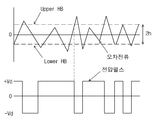
도 3은 본 발명에 따른 오차 전류에 따른 히스테리시스 대역 및 펄스를 보여주는 타이밍도이다.
도 4는 본 발명에 따라 역기전력(back EMF) 위상 편이 오차 보상기를 구비한 일정 대역 히스테리시스 전류 컨트롤러를 갖춘 BLDC 모터 구동장치를 보여주는 블록도이다.
도 5는 정류 상 오차 소스가 없는 역기전력과 상 전류 사이의 관계를 나타내는 타이밍도이다.
도 6은 정류 상 오차 소스를 이용한 역기전력과 상 전류 사이의 관계를 나타내는 타이밍도이다.
도 7은 위상 편이량과 토크 리플 사이의 관계를 나타내는 타이밍도이다.
도 8은 제로-크로싱 위치가 일찍 감지될 때의 토크 리플을 보여주는 타이밍도이다.
도 9는 제로-크로싱 위치가 늦게 감지될 때의 토크 리플을 보여주는 타이밍도이다.
도 10은 제로-크로싱 위치가 일찍 검출되고 적분기에 의해 오차가 모니터 될 때의 부하 토크와 실제 토크 사이의 차이를 보여주는 타이밍도이다.
도 11은 제로-크로싱 위치가 늦게 검출되고 적분기에 의해 오차가 모니터 될 때 하중과 실제 토크 사이의 차이를 보여주는 타이밍도이다.
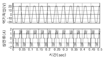
도 12는 15도 전기각의 위상 편이 조건인 경우 일정 대역 히스테리시스 전류 컨트롤러에서 발생한 토크를 보여주는 타이밍도이다.
도 13은 15도 전기각의 위상 편이 조건에서 역기전력 위상 편이 오차 보상기로 일정 대역 히스테리시스 전류 컨트롤러에서 발생한 토크를 보여주는 타이밍도이다.
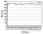
도 14는 동력계에서 BLDC 모터의 측정 속도를 보여주는 타이밍도이다.
도 15는 단지 부정확한 제로-크로싱 검출인 경우 일정 대역 히스테리시스 전류 컨트롤러에서 발생한 토크를 보여주는 타이밍도이다.
도 16은 부정확한 제로-크로싱 검출인 경우 역기전력 위상 편이 오차 보상기를 갖춘 일정 대역 히스테리시스 전류 컨트롤러에서 발생한 토크를 보여주는 타이밍도이다.1 is a timing diagram showing an ideal phase current ignition timing based on back EMF.
2 is a timing diagram showing misalignment between back EMF and phase current.
3 is a timing diagram showing hysteresis bands and pulses according to an error current according to the present invention.
4 is a block diagram showing a BLDC motor drive with a constant band hysteresis current controller with a back EMF phase shift error compensator in accordance with the present invention.
Fig. 5 is a timing diagram showing the relationship between the counter electromotive force and the phase current without a rectified phase error source.
6 is a timing diagram illustrating a relationship between a counter electromotive force and a phase current using a rectified phase error source.
7 is a timing diagram illustrating a relationship between a phase shift amount and torque ripple.
8 is a timing diagram showing torque ripple when the zero-crossing position is detected early.
9 is a timing diagram showing torque ripple when a zero-crossing position is detected late.
10 is a timing diagram showing the difference between the load torque and the actual torque when the zero-crossing position is detected early and the error is monitored by the integrator.
11 is a timing diagram showing the difference between load and actual torque when the zero-crossing position is detected late and the error is monitored by the integrator.
FIG. 12 is a timing diagram illustrating torque generated in a constant band hysteresis current controller under a phase shift condition of a 15 degree electric angle. FIG.
FIG. 13 is a timing diagram illustrating torque generated by a constant band hysteresis current controller as a counter electromotive force phase shift error compensator under a phase shift condition of a 15 degree electric angle.
14 is a timing diagram showing a measurement speed of a BLDC motor in a dynamometer.
FIG. 15 is a timing diagram showing torque generated in a constant band hysteresis current controller when only inaccurate zero-crossing detection.
16 is a timing diagram showing torque generated in a constant band hysteresis current controller with back EMF phase shift error compensator in case of inaccurate zero-crossing detection.
이하, 첨부된 도면들을 참조하여 본 발명에 따른 실시예를 상세히 설명한다. 이 과정에서 도면에 도시된 구성요소의 크기나 형상 등은 설명의 명료성과 편의상 과장되게 도시될 수 있다. Hereinafter, exemplary embodiments of the present invention will be described in detail with reference to the accompanying drawings. In this process, the size or shape of the components shown in the drawings may be exaggerated for clarity and convenience of description.
또한, 본 발명의 구성 및 작용을 고려하여 특별히 정의된 용어들은 사용자, 운용자의 의도 또는 관례에 따라 달라질 수 있다. 이러한 용어들에 대한 정의는 본 명세서 전반에 걸친 내용을 토대로 내려져야 한다. In addition, terms that are specifically defined in consideration of the configuration and operation of the present invention may vary depending on the intention or custom of the user or operator. Definitions of these terms should be made based on the contents throughout the specification.
먼저 BLDC 모터의 상태 공간 모델(state-space model)에 대하여 살펴본다.First, the state-space model of the BLDC motor will be described.
BLDC 모터의 상태 공간 모델은 Matlab/Simulink 시뮬레이션을 위해 구축되고 사용된다. BLDC 모터를 위한 전기자 권선(armature winding)의 수학적 모델은 다음과 같이 표현된다.State-space models of BLDC motors are built and used for Matlab / Simulink simulations. The mathematical model of armature winding for a BLDC motor is expressed as follows.

![]()
![]()

여기서 R은 상 저항(phase resistance)이고 Van, Vbn, Vcn은 중립 전압으로부터의 단자 상 전압 기준이다. 역기전력은 한 상(相)에서 다른 상(相)으로 120도 전기각을 가지며, 하기 수학식 18 내지 수학식 20으로 표현될 수 있다.Where R is phase resistance and V an , V bn and V cn are terminal phase voltage references from neutral voltage. The counter electromotive force has an electrical angle of 120 degrees from one phase to another, and may be represented by
![]()
![]()
![]()
![]()
![]()
![]()
여기서 Ke는 역기전력, ![]()
![]()
![]()
![]()
각각 수학식 15에서 수학식 16을 빼고 수학식 16으로부터 수학식 17을 빼면 하기 수학식 21 내지 수학식 23과 같이 위상 전압을 얻을 수 있다.Subtracting


![]()
![]()
위상 전류 iA, iB, iC의 총합은 0이므로, 수학식 22는 아래와 같이 재정렬된다. Since the sum of the phase currents i A , i B , and i C is 0,

BLDC 모터에서 발생하는 전자기 토크는 다음과 같이 계산된다.The electromagnetic torque generated by the BLDC motor is calculated as follows.

또는 or

여기서 Te는 전자기 토크이고, wm은 모터의 기계적 각속도이다. 정상 상태에서, 전자기 토크는 다음과 같이 표현된다.Where T e is the electromagnetic torque and w m is the mechanical angular velocity of the motor. In the steady state, the electromagnetic torque is expressed as follows.

여기서 TL은 부하 토크, J는 회전자와 결합된 샤프트의 관성이며, β는 마찰 계수이다. 미분 정리에 의해 수학식 21, 수학식 24, 수학식 27은 라플라스 영역으로 변환되어 다음과 같이 상태 공간 모델(state-space model)의 형태로 표현될 수 있다.Where T L is the load torque, J is the inertia of the shaft associated with the rotor, and β is the coefficient of friction. By the differential theorem,


상기한 수학식 28과 수학식 29는 도 4에 도시된 BLDC 모터 구동장치에서 피제어대상인 BLDC 모터(30)를 정의하는 데 필요한 상태 공간 모델(state-space model)로 이용된다.
이하에 본 발명에 따른 BLDC 모터 구동장치를 설명하기 전에 도 1 및 도 2를 참고하여 정류(COMMUTATION) 위상 편이 오차, 토크 및 토크 리플에 대하여 설명한다.Before describing the BLDC motor driving apparatus according to the present invention, the commutation phase shift error, torque and torque ripple will be described with reference to FIGS. 1 and 2.
BLDC 모터 구동 어플리케이션에서, 다양한 위상 보상 기법이 정류 역기전력 위상 편이 오차로 인한 토크 리플을 최소화하기 위해 제안되어 있다. 정류 위상 편이 오차가 발생하면 도 2와 같은 제로-크로싱 위치가 잘못 정렬된다.In BLDC motor drive applications, various phase compensation techniques have been proposed to minimize torque ripple due to rectified back EMF phase shift error. If a rectified phase shift error occurs, the zero-crossing position as shown in FIG. 2 is misaligned.
도 1은 역기전력에 근거한 이상적인 위상 전류 점화 타이밍을 보여준다. 이 경우, 정류 상 전류는 역기전력 제로-크로싱 포인트로부터 30도 전기각 후에 주입되어야 한다. 그러나 오차가 있는 역기전력 제로-크로싱 감지가 발생하면 위상 전류 점화 시간과 주기가 역기전력 제로-크로싱 감지 오차 양만큼 정확히 이동한다. 이는 도 2에 나타난 역기전력과 위상 전류 사이의 오정렬을 초래한다.Figure 1 shows the ideal phase current ignition timing based on back EMF. In this case, the rectified phase current must be injected after 30 degrees electric angle from the back EMF zero-crossing point. However, when erroneous back EMF zero-crossing detection occurs, the phase current ignition time and period shift exactly by the amount of back EMF zero-crossing detection error. This results in a misalignment between the back EMF and the phase current shown in FIG.
토크 방정식은 다음과 같이 수학식 25에 수학식 4와 수학식 23을 적용하여 재배치할 수 있다.The torque equation may be rearranged by applying

그러나, 잘못된 역기전력 제로-크로싱 검출이 발생하면 역기전력은 더 이상 일정하지 않지만 토크는 감소한다. 상응하는 역기전력은 수정되어 후발 역기전력 제로-크로싱 검출에 대해 다음과 같이 표현될 수 있다.However, if false back EMF zero-crossing detection occurs, back EMF is no longer constant but torque is reduced. The corresponding back EMF can be modified and expressed as follows for late back EMF zero-crossing detection.

![]()
![]()
![]()
![]()
여기서 Δt는 지연된 시간의 양이고 ![]()
![]()

이하에 본 발명에 따른 정류 역기전력 위상 편이 오차에 대한 보상 기법에 대하여 도 3 및 도 4를 참고하여 상세하게 설명한다.Hereinafter, a compensation scheme for the rectified back EMF phase shift error according to the present invention will be described in detail with reference to FIGS. 3 and 4.
도 4에는 본 발명의 일 실시예에 따른 역기전력 위상 편이 오차 보상기를 구비한 일정 대역 히스테리시스 전류 컨트롤러를 갖는 BLDC 모터 구동장치가 도시되어 있다.4 illustrates a BLDC motor driving apparatus having a constant band hysteresis current controller having a back EMF phase shift error compensator according to an exemplary embodiment of the present invention.
먼저 도 4를 참조하면, 본 발명에 따른 BLDC 모터 구동장치는 기준 상 전류 생성기(11), 일정 대역 히스테리시스 전류 제어기(12), 역기전력 위상 편이 보상기(13), 적분기(14), 오차 발생기(15), 부하 토크 생성기(16), 각속도/속도 변환기(17), 기준 속도 생성기(18), 역기전력 발생기(19), 기계각/전기각 변환기(20), 토크 계산기(21), 스플리터(22), 멀티플렉서(23,28), 모드 선택 스위치(24), 스플리터(25a,25b), 합산기(26,27) 및 BLDC 모터의 상태 공간 모델(29)을 포함한다. First, referring to FIG. 4, the BLDC motor driving apparatus according to the present invention includes a reference phase
도 4에서 미설명 부재번호 30은 스플리터(22,25a,25b), 합산기(26,27), 멀티플렉서(23,28), BLDC 모터(29) 및 역기전력 발생기(19)를 포함하는 BLDC 모터를 가리키며, 이는 BLDC 모터(30)에 대한 설계 프로그램인 Matlab/Simulink 프로그램을 사용하여 모터의 특성을 용이하게 시뮬레이션하기 위한 목적이다.In FIG. 4,
상기 BLDC 모터(30)의 구조는 상기 수학식 28과 수학식 29에 표시된 상태 공간 모델(state-space model)에 기초하여 표현된 것이다.The structure of the
본 발명에서는 정류(commutation) 토크 리플과 역기전력 위상 편이 오차(error)에 의한 추가 토크 리플을 중점적으로 다룬다. 본 발명에서는 정류(commutation) 토크 리플을 줄이기 위해 일정 대역 히스테리시스 전류 컨트롤러(12)를 이용한다. 일정 대역 히스테리시스 전류 제어 기법은 구현이 매우 간단하고 쉽다. 상당한 양의 토크 리플과 함께 상당한 스위칭 전력 손실을 갖는 PID 컨트롤러와 달리, 일정 대역 히스테리시스 전류 컨트롤러(12)는 히스테리시스 대역폭으로 토크 리플 양과 스위칭 전력 손실을 쉽게 제어할 수 있다.The present invention focuses on additional torque ripple due to commutation torque ripple and back EMF phase shift error. In the present invention, a constant band hysteresis
상기 BLDC 모터 상태 공간 모델(29)로부터 3상 전류(phase current)(iA,iB,iC)와, 기계 각속도(wm) 및 모터 회전자의 회전위치를 알 수 있는 회전 각속도(rad)가 스플리터(22)로 출력된다. 이중에 3상 전류(phase current)(iA,iB,iC)는 스플리터(22)로부터 멀티플렉서(MUX)(23)를 통하여 토크 계산기(21)에 공급됨과 동시에 일정 대역 히스테리시스 전류 제어기(12)에 피드백 상 전류(phase current)(iA,iB,iC)로 공급된다.From the BLDC motor
상기 기계 각속도(wm)와 회전 각속도(rad)는 역기전력 발생기(19)에 인가되며, 역기전력 발생기(19)는 기계각/전기각 변환기(20)로 회전자의 기계 각속도(wm)를 출력하고, 토크 계산기(21)로 3상 자속값을 출력하며, 3상 BLDC 모터 상태 공간 모델(30)의 스플리터(25a)에 3상 역기전력(eA,eB,eC)을 생성하여 출력한다.The machine angular velocity (w m ) and rotational angular velocity (rad) are applied to the counter electromotive force generator (19), and the counter electromotive force generator (19) outputs the machine angular velocity (w m ) of the rotor to the machine angle / electric angle converter (20). and outputting the three-phase flux value in the
상기 BLDC 모터(30)로부터 발생되는 각종 출력 신호는 예를 들어, 홀(Hall) 센서나 전압검출기 등을 사용하여 검출할 수 있다. Various output signals generated from the
상기 기계각/전기각 변환기(20)는 회전자의 기계 각속도(wm)를 전기각(![]()
![]()
상기 토크 계산기(21)는 3상 전류(phase current)(iA,iB,iC)와 3상 자속값으로부터 출력 토크(Te)를 계산하여 오차 발생기(15)에 공급한다.The
또한, 상기 회전 각속도(rad)는 각속도/속도 변환기(17)에서 각속도(rad)를 속도(rpm)로 변환된 후, 기준 상 전류 생성기(11)에 실제 모터의 출력 속도(rpm)를 공급한다.In addition, the rotational angular velocity (rad) is converted from the angular velocity (rad) to the speed (rpm) in the angular velocity /
한편, 오차 발생기(15)는 부하 토크 발생기(16)로부터 수신한 사용자가 설정한 원하는 부하 토크(load torque)(TL)와 토크 계산기(21)로부터 수신한 실제 모터의 출력 토크(Te)를 비교하여 오차값을 출력한다. 즉, 오차 발생기(15)는 출력 토크(Te)가 부하 토크(TL)보다 더 크면 역기전력 제로-크로싱 감지시에 상이 빠른 것으로 판단하여, 속도를 감소시키도록 오차값을 (-)값을 갖도록 하고, 출력 토크(Te)가 부하 토크(TL)보다 더 작으면 상기와 반대로 역기전력 제로-크로싱 감지시에 상이 느린 것으로 판단하여, 속도를 증가시키도록 오차값을 (+)값을 갖도록 설정된다.On the other hand, the
상기 오차값은 멀티플렉서(MUX)(28)를 통하여 BLDC 모터(30)로 공급됨과 동시에 적분기(14)로 공급된다.The error value is supplied to the
적분기(14)는 오차 발생기(15)로부터 오차값을 받아서 미리 설정된 샘플링 주기별로 적분된 값을 생성하여 역기전력 위상 편이 보상기(13)로 출력한다. The
상기 역기전력 위상 편이 보상기(13)는 적분기에서 누적된 오차값이 음의 값인 경우 출력을 증가시키고, 오차값이 양의 값인 경우 출력을 감소시키는 방법으로 역기전력 위상 편이를 보상한다.The back EMF
상기 역기전력 위상 편이 보상방법은 도 5 내지 도 16을 참고하여 추후에 상세하게 설명한다.The counter electromotive force phase shift compensation method will be described in detail later with reference to FIGS. 5 to 16.
한편, 기준 상 전류 생성기(11)는 속도 PID 제어기로 역할을 하며, 기준 속도 생성기(18)에서 생성된 기준 속도(reference speed), 즉 사용자가 지정한 속도값을 수신하고 이를 각속도/속도 변환기(17)에서 수신한 모터의 실제 출력 속도(rpm)와 비교하여 일정 대역 히스테리시스 전류 제어기(12)에 기준 상 전류(![]()
![]()
즉, 비교결과, 실제 출력 속도(rpm)가 기준 속도보다 작으면 기준 상 전류(![]()
![]()
![]()
![]()
상기 일정 대역 히스테리시스 전류 제어기(12)는 기준 상 전류 생성기(11)로부터 기준 상 전류(![]()
![]()
![]()
![]()
상기 일정 대역 히스테리시스 전류 제어기(12)는 도 3에 도시된 일정 대역 히스테리시스 방식으로 PWM 출력 전압을 제어하거나 PID 방식으로 출력 전압을 제어할 수 있다.The constant band hysteresis
본 발명에서는 출력 전압을 일정 대역 히스테리시스 방식으로 제어하여 모터로 출력하도록 모드 선택 스위치(24)가 미리 설정되어 있다.In the present invention, the
이하에서는 도 3을 참고하여 본 발명에 따른 일정 대역 히스테리시스 전류 제어기(12)를 이용한 히스테리시스 방식의 PWM 출력 전압 제어에 대하여 설명한다.Hereinafter, the hysteresis-type PWM output voltage control using the constant band hysteresis
일정 대역 히스테리시스 전류 제어기(12)에서 피드백 상 전류(phase current)(iA,iB,iC)는 속도 PID 제어기에 의해 제어되는 기준 상 전류(reference phase current)(![]()
![]()
도 3은 상하 히스테리시스 대역(Upper HB, Lower HB)과 히스테리시스 대역 범위에서 속도 변화가 어떻게 떨어지는 지를 보여준다. 현재 전류 오차(error)가 상위 히스테리시스 대역(Upper HB)을 초과하면, + Vd 펄스가 -Vd 펄스로 떨어지게 하여 모터에 대한 출력 전압은 펄스폭이 감소하게 된다. 상기와 반대로 전류 오차(error)가 더 낮은 히스테리시스 대역(Lower HB) 아래로 내려가는 경우, + Vd 펄스가 주어지므로 모터에 대한 출력 전압은 펄스폭이 증가하게 된다. 3 shows how the speed change falls in the upper and lower hysteresis bands (Upper HB, Lower HB) and the hysteresis band range. If the current current error exceeds the upper hysteresis band (Upper HB), the + V d pulses drop to -V d pulses so that the output voltage to the motor decreases in pulse width. Contrary to the above, when the current error falls below the lower hysteresis band Lower HB, the + V d pulse is given so that the output voltage to the motor increases in the pulse width.
피드백 상 전류(iA,iB,iC)는 오차 양이 히스테리시스 대역폭에 제한되는 기준 상 전류(reference phase current)(![]()
![]()
본 발명에서는 정류 토오크 리플에 추가하여, 역기전력 제로-크로싱(back EMF zero-crossing) 감지로 인해 정류 기간 동안 역기전력 편이 오차로 인한 과부하 토크 리플이 발생한다. 일정 대역 히스테리시스 전류 컨트롤러(12)만으로는 전체 토크 리플의 최소화를 보장할 수 없다. 피드백 상 전류가 기준 상 전류를 잘 따르더라도 역기전력 위상 편이 오프셋이 존재하면 추가 토크 리플이 항상 발생한다. In the present invention, in addition to the rectified torque ripple, overload torque ripple occurs due to the back EMF zero-crossing error due to the back EMF zero-crossing detection. The constant band hysteresis
토크 리플을 최소화하는 유일하고 간단한 솔루션은 역기전력 위상 편이 오차 보정기(13)로 위상 편이를 교정하는 것이다. 토크 리플의 양과 모양은 위상 편이 량과 역기전력 위상 이동의 방향에 따라 달라진다. 따라서, 본 발명에서는 위상 적분 오차 모니터로서 단순한 적분기(14)를 채택함으로써 역기전력 위상의 양과 방향을 모니터링하고 이에 따라 검출된 위상 편이 오차를 보상한다. The only simple solution to minimize torque ripple is to correct the phase shift with a back EMF phase
이하에 상기와 같이 구성된 본 발명에 따른 BLDC 모터 구동장치의 역기전력 위상 편이와 오차 보상 및 토크 리플 저감에 대한 효과를 확인하기 위한 시뮬레이션을 실시하고 그 실험 결과를 소개한다.In the following, the simulation is performed to check the effects on the counter electromotive force phase shift, error compensation, and torque ripple reduction of the BLDC motor driving apparatus according to the present invention configured as described above, and introduces the experimental results.
BLDC 모터 구동장치를 위한 역기전력 위상 변이 보정기(13) 알고리즘을 이용한 일정 대역 히스테리시스 전류 제어가 Matlab/Simulink 프로그램을 사용하여 개발 및 시뮬레이션 되었다. 이 시뮬레이션에서 800V의 DC 전압이 5N.m 부하 토크로 인가되고 기준 속도는 1000rpm으로 설정되었다. BLDC 모터(30)의 상태 공간 모델은 도 4에 도시된 바와 같이 구현하였다.Constant band hysteresis current control using the back EMF phase shift compensator algorithm for BLDC motor drive was developed and simulated using the Matlab / Simulink program. In this simulation, a DC voltage of 800V was applied at 5N.m load torque and the reference speed was set at 1000rpm. The state space model of the
시뮬레이션에 사용된 BLDC 모터의 파라미터(PARAMETER)는 하기 표 1과 같다.The parameters of the BLDC motor used in the simulation are shown in Table 1 below.
이 시뮬레이션에 사용된 BLDC 모터는 상기 표 1에 표시된 파라미터를 갖는다.The BLDC motor used in this simulation has the parameters shown in Table 1 above.
정류 위상 시프트 오차가 없는 일정 대역 히스테리시스 전류 제어기(12)를 사용한 BLDC 모터 구동장치의 폐 루프 성능으로부터 역기전력과 상 전류 사이의 관계가 도 5에 나와 있다.The relationship between back EMF and phase current from the closed loop performance of a BLDC motor drive using constant band hysteresis
그러나, 정류 위상 편이 오차 소스가 간섭할 때, 상 전류는 도 6과 같이 지연된다. 상 전류는 역기전력 위상 편이 오차로 인해 감소된 토크를 보상하기 위해 증가하는 것으로 관측되고, 제로-크로싱 점 검출 지연량만큼 정확하게 편이가 이루어진다.However, when the rectified phase shift error source interferes, the phase current is delayed as shown in FIG. The phase current is observed to increase to compensate for the reduced torque due to the back EMF phase shift error, which is shifted exactly by the amount of zero-crossing point detection delay.
도 7에서 0.05초까지 위상 편이가 적용되지 않았고 0.1 초에 5도의 전기각이 적용된 다음 다시 5도의 전기각이 적용되어 총 10도의 전기각이 변경되었다. 위상 편이 양에 따라, 토크 리플의 진폭은 상 전류 편이 양에 의존한다고 결론 지은 토크 리플 량의 증가가 관찰된다.In FIG. 7, the phase shift was not applied until 0.05 seconds, the electric angle of 5 degrees was applied in 0.1 second, and then the electric angle of 5 degrees was applied again, thereby changing the electric angle of 10 degrees in total. Depending on the amount of phase shift, an increase in the amount of torque ripple concluded that the amplitude of the torque ripple depends on the amount of phase current shift.
그러나, 역기전력 제로 크로싱 위치가 일찍 또는 늦게 감지되는지 여부를 판별하기는 어렵다. 역기전력 위상 편이 오차를 보상하기 위해서는 위상 전류의 방향도 표시해야 한다. 본 발명에서는 토크 리플의 모양이 위상 편이 방향에 따라 모양이 변하기 때문에 밀접하게 분석된다. 음의 방향과 양의 방향에서 15도 전기각 위상 편이에 의해 야기되는 대응 토크는 각각 도 8 및 도 9에 표시된다.However, it is difficult to determine whether the counter electromotive force zero crossing position is detected early or late. To compensate for back EMF phase shift errors, the direction of the phase current must also be indicated. In the present invention, the shape of the torque ripple is closely analyzed because the shape changes in accordance with the phase shift direction. The corresponding torques caused by the 15 degree electrical angle phase shift in the negative and positive directions are shown in FIGS. 8 and 9, respectively.
도 8 및 도 9에 도시된 바와 같이, 음의 방향 및 양의 방향의 위상 편이 오차에 대하여 토크 리플의 상이한 왜곡이 관찰되고, 이러한 왜곡은 위상 편이의 방향을 식별하는 데 사용될 수 있다. 부하 토크와 실제 출력 토크 사이의 오차는 도 10과 도 11의 적분기(14)의 출력과 함께 표시된다.As shown in Figures 8 and 9, different distortions of the torque ripple are observed for phase shift errors in the negative and positive directions, which can be used to identify the direction of the phase shift. The error between the load torque and the actual output torque is indicated with the output of the
적분기(14)의 출력을 관찰함으로써, 위상 편이(phase shift)의 방향을 결정할 수 있다. 만약 적분기(14)의 출력이 도 10에 도시된 바와 같이 오목한 형상을 갖는다면, 조기 제로-크로싱 위치 검출이 가정된다. By observing the output of the
한편, 도 11과 같이 볼록 형상을 갖는 경우, 지연 제로-크로싱 위치 검출이 가정된다. 도 12와 도 13은 일정 대역 히스테리시스 전류 컨트롤러(11)와 역기전력 위상 오차 보상기(13)로 달성되는 토크 리플의 감소를 보여준다.On the other hand, when having a convex shape as shown in Fig. 11, delay zero-crossing position detection is assumed. 12 and 13 show the reduction in torque ripple achieved by the constant band hysteresis
상기 실험에서, Valid Magnetics에 의해 제조된 히스테리시스 브레이크 동력계(BHD-144)는 역기전력 위상 편이 오차로 인한 토크 리플을 분석하는데 사용된다. 하기 표 2는 동력계(dynamometer)를 사용하여 토크 리플을 측정하기 위한 일반적인 테스트 설정을 보여준다.In this experiment, a hysteresis brake dynamometer (BHD-144) manufactured by Valid Magnetics is used to analyze torque ripple due to back EMF phase shift error. Table 2 below shows a typical test setup for measuring torque ripple using a dynamometer.
표 2는 히스테리시스 브레이크 동력계(BHD-144)의 특정 파라미터를 나타낸다. 토크 리플은 도 14에 도시된 바와 같이 변화하는 부하 토크를 갖는 360rpm의 속도로 측정되었다.Table 2 shows the specific parameters of the hysteresis brake dynamometer (BHD-144). Torque ripple was measured at a speed of 360 rpm with varying load torque as shown in FIG.
도 15는 부정확한 제로-크로싱 검출 하에서 0.5N.m에서 1.5N.m까지 변화하는 부하 토크만으로 일정 밴드 히스테리시스 전류 컨트롤러(12)로부터 측정된 토크를 보여준다. 실험은 0.5N.m 부하 토크로 시작되었으며, 추가 0.5N.m 부하 토크가 매 5초마다 추가되어 총 1.5N.m 부하 토크가 발생한다. FIG. 15 shows the torque measured from constant band hysteresis
도 16에는 역기전력 위상 편이 오차 보상기(13)를 구비한 일정 대역 히스테리시스 전류 제어기(12)의 측정된 토크가 표시되어 있다.16 shows the measured torque of a constant band hysteresis
일정 대역 히스테리시스 전류 제어기(12)만을 사용할 때 측정된 토크와는 달리 본 발명에 따라 역기전력 위상 편이 오차 보상기(13)를 채용하는 경우 역기전력 위상 편이 오차에 의해 발생하는 토크 리플을 줄이는데 효과적임을 보여주며, 제안된 회로는 정류 기간 동안 토크 리플을 최소화하는데 적합하다.Unlike the torque measured when using only the constant band hysteresis
상기한 바와 같이, 본 발명에서는 역기전력 위상 편이 보상기를 이용한 일정 대역 히스테리시스 전류 제어기를 제안하며, 정류 역기전력 위상 편이 오차 및 정류 토크 리플에 의해 발생하는 토크 리플을 감소시키는 것이 적절하다는 것을 보여준다. As described above, the present invention proposes a constant band hysteresis current controller using a back EMF phase shift compensator and shows that it is appropriate to reduce the torque ripple caused by the rectified back EMF phase shift error and the rectified torque ripple.
본 발명은 역기전력 위상 편이 보상기를 갖는 일정 대역 히스테리시스 전류 제어기를 이용하여, 정류 역기전력 위상 편이 오차 및 정류 토크 리플에 의해 발생하는 토크 리플을 감소시키는 BLDC 모터 구동장치에 적용될 수 있다. The present invention can be applied to a BLDC motor driving device using a constant band hysteresis current controller having a counter electromotive force phase shift compensator to reduce the torque ripple caused by the rectified counter electromotive force phase shift error and the rectified torque ripple.
11: 기준 상 전류 생성기
12: 일정 대역 히스테리시스 전류 제어기
13: 역기전력 위상 편이 보상기
14: 적분기
15: 오차 발생기
16: 부하 토크 생성기
17: 각속도/속도 변환기
18: 기준 속도 생성기
19: 역기전력 발생기
20: 기계각/전기각 변환기
21: 토크 계산기
22: 스플리터
23,28: MUX
24: 모드 선택 스위치
25a,25b: 스플리터
26,27: 합산기
29: BLDC 모터 상태 공간 모델
30: BLDC 모터11: Reference Phase Current Generator 12: Constant Band Hysteresis Current Controller
13: Back EMF Phase Shift Compensator 14: Integrator
15: error generator 16: load torque generator
17: angular velocity / speed converter 18: reference velocity generator
19: counter electromotive force generator 20: machine angle / electric angle converter
21: Torque Calculator 22: Splitter
23, 28: MUX 24: mode selector switch
25a, 25b:
29: BLDC motor state space model 30: BLDC motor
Claims (5)
상기 기계 각속도를 전기각으로 변환하여 출력하는 기계각/전기각 변환기;
상기 회전 각속도를 속도로 변환하여 모터의 출력 속도를 출력하는 각속도/속도 변환기;
상기 모터의 실제 출력 속도를 기준 속도 생성기에서 생성된 기준 속도와 비교하여 기준 상 전류를 발생하는 기준 상 전류 생성기; 및
일정한 히스테리시스 대역(hysteresis band)을 갖는 일정 대역 비교기를 사용하여 상기 피드백되는 3상 전류를 기준 상 전류와 비교하여 전류 오차를 발생하고, 상기 전류 오차를 상위 및 하위 히스테리시스 대역과 비교하여 PWM(펄스폭변조) 출력 전압의 펄스폭을 제어하는 일정 대역 히스테리시스 전류 제어기;를 포함하는 BLDC 모터 구동장치.A BLDC motor driving device for driving a three-phase BLDC motor based on the three-phase current of the three-phase BL (DC) brushless DC motor, the angular velocity of the machine and the rotational angular velocity of the rotational position of the motor rotor
A machine angle / electric angle converter for converting and outputting the machine angular velocity into an electric angle;
An angular velocity / speed converter for converting the rotational angular velocity into a speed to output an output speed of a motor;
A reference phase current generator for generating a reference phase current by comparing the actual output speed of the motor with a reference speed generated by a reference speed generator; And
Using a constant band comparator having a constant hysteresis band, a current error is generated by comparing the feedback three-phase current with a reference phase current, and comparing the current error with upper and lower hysteresis bands to PWM (pulse width). Modulation) constant-band hysteresis current controller for controlling the pulse width of the output voltage.
상기 기준 상 전류 생성기는 실제 출력 속도가 기준 속도보다 작으면 기준 상 전류를 증가시키고, 실제 출력 속도가 기준 속도보다 더 크면 기준 상 전류를 감소시키는 BLDC 모터 구동장치.The method of claim 1,
And the reference phase current generator increases the reference phase current if the actual output speed is less than the reference speed, and decreases the reference phase current if the actual output speed is greater than the reference speed.
상기 3상 전류(phase current)(iA,iB,iC)와 3상 자속값으로부터 출력 토크(Te)를 계산하여 출력하는 토크 계산기;
상기 부하 토크 발생기로부터 수신한 사용자가 설정한 원하는 부하 토크(load torque)(TL)와 토크 계산기로부터 수신한 실제 모터의 출력 토크(Te)를 비교하여 오차값을 출력하는 오차 발생기;
상기 오차 발생기로부터 오차값을 받아서 미리 설정된 샘플링 주기별로 적분된 값을 생성하는 적분기; 및
상기 적분기에서 누적된 오차값이 음의 값인 경우 출력을 증가시키고, 오차값이 양의 값인 경우 출력을 감소시키는 방법으로 역기전력 위상 편이를 보상하는 역기전력 위상 편이 보상기;를 더 포함하며,
상기 오차 발생기는 출력 토크가 부하 토크보다 더 크면 역기전력 제로-크로싱 감지시에 상이 빠른 것으로 판단하여, 속도를 감소시키도록 오차값이 (-)값을 갖도록 하고,
상기 출력 토크가 부하 토크보다 더 작으면 상기와 반대로 역기전력 제로-크로싱 감지시에 상이 느린 것으로 판단하여, 속도를 증가시키도록 오차값이 (+)값을 갖도록 설정하는 BLDC 모터 구동장치.The method of claim 1,
The three-phase current (phase current) (i A, i B, i C) and a torque calculator for calculating and outputting the output torque (T e) from the three phase flux values;
An error generator for outputting an error value by comparing the load torque generator a desired load torque set by the user received from the (load torque) (T L) and the output torque (T e) of the actual motor received from the torque converter;
An integrator that receives an error value from the error generator and generates an integrated value for each preset sampling period; And
A counter electromotive force phase shift compensator for compensating the counter electromotive force phase shift by increasing the output when the error value accumulated in the integrator is a negative value and decreasing the output when the error value is a positive value;
When the output torque is greater than the load torque, the error generator determines that the phase is high when the counter electromotive force zero-crossing is detected, so that the error value has a negative value to reduce the speed.
And if the output torque is smaller than the load torque, determine that the phase is slow upon counter electromotive force zero-crossing detection, and set the error value to have a positive value so as to increase the speed.
상기 일정 대역 히스테리시스 전류 제어기는 일정한 히스테리시스 대역(hysteresis band)을 갖는 일정 대역 비교기를 사용하여 피드백 상 전류를 기준 상 전류와 비교하는 전류 오차를 발생하는 BLDC 모터 구동장치.The method of claim 1,
And the constant band hysteresis current controller generates a current error comparing the feedback phase current with the reference phase current using a constant band comparator having a constant hysteresis band.
상기 전류 오차(error)가 상위 히스테리시스 대역(Upper HB)을 초과하면, PWM 출력 전압의 펄스폭을 감소시키고,
상기 전류 오차가 하위 히스테리시스 대역(Lower HB) 아래로 내려가는 경우, PWM 출력 전압의 펄스폭을 증가시키는 BLDC 모터 구동장치.The method of claim 4, wherein
If the current error exceeds the upper hysteresis band (Upper HB), the pulse width of the PWM output voltage is reduced,
BLDC motor driving device to increase the pulse width of the PWM output voltage when the current error falls below the lower hysteresis band (Lower HB).
Priority Applications (1)
| Application Number | Priority Date | Filing Date | Title |
|---|---|---|---|
| KR1020180049552A KR102166365B1 (en) | 2018-04-30 | 2018-04-30 | BLDC Motor Driving Apparatus Having Constant Band Hysteresis Current Controller with Back EMF Phase Shift Error Compensator |
Applications Claiming Priority (1)
| Application Number | Priority Date | Filing Date | Title |
|---|---|---|---|
| KR1020180049552A KR102166365B1 (en) | 2018-04-30 | 2018-04-30 | BLDC Motor Driving Apparatus Having Constant Band Hysteresis Current Controller with Back EMF Phase Shift Error Compensator |
Publications (2)
| Publication Number | Publication Date |
|---|---|
| KR20190125580A true KR20190125580A (en) | 2019-11-07 |
| KR102166365B1 KR102166365B1 (en) | 2020-10-15 |
Family
ID=68579020
Family Applications (1)
| Application Number | Title | Priority Date | Filing Date |
|---|---|---|---|
| KR1020180049552A KR102166365B1 (en) | 2018-04-30 | 2018-04-30 | BLDC Motor Driving Apparatus Having Constant Band Hysteresis Current Controller with Back EMF Phase Shift Error Compensator |
Country Status (1)
| Country | Link |
|---|---|
| KR (1) | KR102166365B1 (en) |
Citations (3)
| Publication number | Priority date | Publication date | Assignee | Title |
|---|---|---|---|---|
| KR20080053992A (en) * | 2006-12-12 | 2008-06-17 | 현대자동차주식회사 | Motor control system using an inverter voltage control method |
| KR101343312B1 (en) | 2012-09-20 | 2013-12-18 | (주)위더스비젼 | Three phase sensoerless brushless direct current motor and system for controlling driving thereof |
| KR20160082637A (en) * | 2014-12-26 | 2016-07-08 | 주식회사 케이씨씨 | Two-component Coating Compositions And Preparation Thereof |
-
2018
- 2018-04-30 KR KR1020180049552A patent/KR102166365B1/en active IP Right Grant
Patent Citations (3)
| Publication number | Priority date | Publication date | Assignee | Title |
|---|---|---|---|---|
| KR20080053992A (en) * | 2006-12-12 | 2008-06-17 | 현대자동차주식회사 | Motor control system using an inverter voltage control method |
| KR101343312B1 (en) | 2012-09-20 | 2013-12-18 | (주)위더스비젼 | Three phase sensoerless brushless direct current motor and system for controlling driving thereof |
| KR20160082637A (en) * | 2014-12-26 | 2016-07-08 | 주식회사 케이씨씨 | Two-component Coating Compositions And Preparation Thereof |
Also Published As
| Publication number | Publication date |
|---|---|
| KR102166365B1 (en) | 2020-10-15 |
Similar Documents
| Publication | Publication Date | Title |
|---|---|---|
| Bateman et al. | Sensorless operation of an ultra-high-speed switched reluctance machine | |
| KR100791814B1 (en) | Control Method of Sensorless BLDC Motor | |
| JP3972124B2 (en) | Synchronous motor speed control device | |
| CN104079217B (en) | Motor control assembly and magnetic pole position estimation method | |
| US20070296371A1 (en) | Position sensorless control apparatus for synchronous motor | |
| US20130043814A1 (en) | System and method for synchronizing sinusoidal drive to permanent magnet motor without distorting drive voltage | |
| JP2009044935A (en) | Motor control device and compressor | |
| JP2006054995A (en) | Drive control device and method for ac motor | |
| JP4241218B2 (en) | AC motor control device and AC motor system | |
| JP2010063208A (en) | Drive system for synchronous motor, and controller used for this | |
| US7405534B2 (en) | Apparatus and method for controlling velocity of motor | |
| JP2021106490A (en) | Method and apparatus for quasi-sensorless adaptive control of switched reluctance motor drive | |
| WO2016161213A1 (en) | Fractional delay adjustment in a field-oriented control architecture | |
| TW201710924A (en) | Method for estimating parameters of the induction machine by the polynomial regression | |
| JP6293401B2 (en) | Motor controller for air conditioner and air conditioner | |
| Kan et al. | Adaptive soft starting method with current limit strategy for sensorless BLDC motors | |
| Sanita et al. | Modelling and simulation of four quadrant operation of three phase brushless DC motor with hysteresis current controller | |
| JP3767896B2 (en) | Stepping motor drive device | |
| JP4051833B2 (en) | Vector controller for permanent magnet synchronous motor | |
| JP2010035351A (en) | Device for estimating rotor position of synchronous electric motor | |
| KR102166365B1 (en) | BLDC Motor Driving Apparatus Having Constant Band Hysteresis Current Controller with Back EMF Phase Shift Error Compensator | |
| KR20070048522A (en) | Apparatus for estimating stator resistance of motor and method thereof | |
| JP2017205017A (en) | Motor control device of air conditioner, and air conditioner | |
| JP7108834B2 (en) | power generator | |
| Tang et al. | Assessments of dead beat current control for high speed permanent magnet synchronous motor drives |
Legal Events
| Date | Code | Title | Description |
|---|---|---|---|
| A201 | Request for examination | ||
| E902 | Notification of reason for refusal | ||
| E701 | Decision to grant or registration of patent right |