KR20190108965A - Display apparatus and controlling method thereof - Google Patents
Display apparatus and controlling method thereof Download PDFInfo
- Publication number
- KR20190108965A KR20190108965A KR1020180030700A KR20180030700A KR20190108965A KR 20190108965 A KR20190108965 A KR 20190108965A KR 1020180030700 A KR1020180030700 A KR 1020180030700A KR 20180030700 A KR20180030700 A KR 20180030700A KR 20190108965 A KR20190108965 A KR 20190108965A
- Authority
- KR
- South Korea
- Prior art keywords
- temperature
- light emitting
- emitting diode
- dew point
- ambient
- Prior art date
Links
Images


Classifications
-
- G—PHYSICS
- G09—EDUCATION; CRYPTOGRAPHY; DISPLAY; ADVERTISING; SEALS
- G09G—ARRANGEMENTS OR CIRCUITS FOR CONTROL OF INDICATING DEVICES USING STATIC MEANS TO PRESENT VARIABLE INFORMATION
- G09G3/00—Control arrangements or circuits, of interest only in connection with visual indicators other than cathode-ray tubes
- G09G3/20—Control arrangements or circuits, of interest only in connection with visual indicators other than cathode-ray tubes for presentation of an assembly of a number of characters, e.g. a page, by composing the assembly by combination of individual elements arranged in a matrix no fixed position being assigned to or needed to be assigned to the individual characters or partial characters
-
- H—ELECTRICITY
- H05—ELECTRIC TECHNIQUES NOT OTHERWISE PROVIDED FOR
- H05B—ELECTRIC HEATING; ELECTRIC LIGHT SOURCES NOT OTHERWISE PROVIDED FOR; CIRCUIT ARRANGEMENTS FOR ELECTRIC LIGHT SOURCES, IN GENERAL
- H05B1/00—Details of electric heating devices
- H05B1/02—Automatic switching arrangements specially adapted to apparatus ; Control of heating devices
- H05B1/0227—Applications
-
- G—PHYSICS
- G09—EDUCATION; CRYPTOGRAPHY; DISPLAY; ADVERTISING; SEALS
- G09G—ARRANGEMENTS OR CIRCUITS FOR CONTROL OF INDICATING DEVICES USING STATIC MEANS TO PRESENT VARIABLE INFORMATION
- G09G3/00—Control arrangements or circuits, of interest only in connection with visual indicators other than cathode-ray tubes
- G09G3/20—Control arrangements or circuits, of interest only in connection with visual indicators other than cathode-ray tubes for presentation of an assembly of a number of characters, e.g. a page, by composing the assembly by combination of individual elements arranged in a matrix no fixed position being assigned to or needed to be assigned to the individual characters or partial characters
- G09G3/22—Control arrangements or circuits, of interest only in connection with visual indicators other than cathode-ray tubes for presentation of an assembly of a number of characters, e.g. a page, by composing the assembly by combination of individual elements arranged in a matrix no fixed position being assigned to or needed to be assigned to the individual characters or partial characters using controlled light sources
- G09G3/30—Control arrangements or circuits, of interest only in connection with visual indicators other than cathode-ray tubes for presentation of an assembly of a number of characters, e.g. a page, by composing the assembly by combination of individual elements arranged in a matrix no fixed position being assigned to or needed to be assigned to the individual characters or partial characters using controlled light sources using electroluminescent panels
- G09G3/32—Control arrangements or circuits, of interest only in connection with visual indicators other than cathode-ray tubes for presentation of an assembly of a number of characters, e.g. a page, by composing the assembly by combination of individual elements arranged in a matrix no fixed position being assigned to or needed to be assigned to the individual characters or partial characters using controlled light sources using electroluminescent panels semiconductive, e.g. using light-emitting diodes [LED]
-
- G—PHYSICS
- G06—COMPUTING; CALCULATING OR COUNTING
- G06F—ELECTRIC DIGITAL DATA PROCESSING
- G06F3/00—Input arrangements for transferring data to be processed into a form capable of being handled by the computer; Output arrangements for transferring data from processing unit to output unit, e.g. interface arrangements
- G06F3/14—Digital output to display device ; Cooperation and interconnection of the display device with other functional units
- G06F3/1423—Digital output to display device ; Cooperation and interconnection of the display device with other functional units controlling a plurality of local displays, e.g. CRT and flat panel display
- G06F3/1446—Digital output to display device ; Cooperation and interconnection of the display device with other functional units controlling a plurality of local displays, e.g. CRT and flat panel display display composed of modules, e.g. video walls
-
- G—PHYSICS
- G09—EDUCATION; CRYPTOGRAPHY; DISPLAY; ADVERTISING; SEALS
- G09G—ARRANGEMENTS OR CIRCUITS FOR CONTROL OF INDICATING DEVICES USING STATIC MEANS TO PRESENT VARIABLE INFORMATION
- G09G3/00—Control arrangements or circuits, of interest only in connection with visual indicators other than cathode-ray tubes
- G09G3/20—Control arrangements or circuits, of interest only in connection with visual indicators other than cathode-ray tubes for presentation of an assembly of a number of characters, e.g. a page, by composing the assembly by combination of individual elements arranged in a matrix no fixed position being assigned to or needed to be assigned to the individual characters or partial characters
- G09G3/22—Control arrangements or circuits, of interest only in connection with visual indicators other than cathode-ray tubes for presentation of an assembly of a number of characters, e.g. a page, by composing the assembly by combination of individual elements arranged in a matrix no fixed position being assigned to or needed to be assigned to the individual characters or partial characters using controlled light sources
- G09G3/30—Control arrangements or circuits, of interest only in connection with visual indicators other than cathode-ray tubes for presentation of an assembly of a number of characters, e.g. a page, by composing the assembly by combination of individual elements arranged in a matrix no fixed position being assigned to or needed to be assigned to the individual characters or partial characters using controlled light sources using electroluminescent panels
- G09G3/32—Control arrangements or circuits, of interest only in connection with visual indicators other than cathode-ray tubes for presentation of an assembly of a number of characters, e.g. a page, by composing the assembly by combination of individual elements arranged in a matrix no fixed position being assigned to or needed to be assigned to the individual characters or partial characters using controlled light sources using electroluminescent panels semiconductive, e.g. using light-emitting diodes [LED]
- G09G3/3208—Control arrangements or circuits, of interest only in connection with visual indicators other than cathode-ray tubes for presentation of an assembly of a number of characters, e.g. a page, by composing the assembly by combination of individual elements arranged in a matrix no fixed position being assigned to or needed to be assigned to the individual characters or partial characters using controlled light sources using electroluminescent panels semiconductive, e.g. using light-emitting diodes [LED] organic, e.g. using organic light-emitting diodes [OLED]
-
- H—ELECTRICITY
- H05—ELECTRIC TECHNIQUES NOT OTHERWISE PROVIDED FOR
- H05B—ELECTRIC HEATING; ELECTRIC LIGHT SOURCES NOT OTHERWISE PROVIDED FOR; CIRCUIT ARRANGEMENTS FOR ELECTRIC LIGHT SOURCES, IN GENERAL
- H05B1/00—Details of electric heating devices
- H05B1/02—Automatic switching arrangements specially adapted to apparatus ; Control of heating devices
-
- H—ELECTRICITY
- H05—ELECTRIC TECHNIQUES NOT OTHERWISE PROVIDED FOR
- H05K—PRINTED CIRCUITS; CASINGS OR CONSTRUCTIONAL DETAILS OF ELECTRIC APPARATUS; MANUFACTURE OF ASSEMBLAGES OF ELECTRICAL COMPONENTS
- H05K7/00—Constructional details common to different types of electric apparatus
- H05K7/20—Modifications to facilitate cooling, ventilating, or heating
- H05K7/20954—Modifications to facilitate cooling, ventilating, or heating for display panels
- H05K7/20972—Forced ventilation, e.g. on heat dissipaters coupled to components
-
- G—PHYSICS
- G09—EDUCATION; CRYPTOGRAPHY; DISPLAY; ADVERTISING; SEALS
- G09F—DISPLAYING; ADVERTISING; SIGNS; LABELS OR NAME-PLATES; SEALS
- G09F9/00—Indicating arrangements for variable information in which the information is built-up on a support by selection or combination of individual elements
- G09F9/30—Indicating arrangements for variable information in which the information is built-up on a support by selection or combination of individual elements in which the desired character or characters are formed by combining individual elements
- G09F9/302—Indicating arrangements for variable information in which the information is built-up on a support by selection or combination of individual elements in which the desired character or characters are formed by combining individual elements characterised by the form or geometrical disposition of the individual elements
- G09F9/3026—Video wall, i.e. stackable semiconductor matrix display modules
-
- G—PHYSICS
- G09—EDUCATION; CRYPTOGRAPHY; DISPLAY; ADVERTISING; SEALS
- G09G—ARRANGEMENTS OR CIRCUITS FOR CONTROL OF INDICATING DEVICES USING STATIC MEANS TO PRESENT VARIABLE INFORMATION
- G09G2300/00—Aspects of the constitution of display devices
- G09G2300/02—Composition of display devices
- G09G2300/026—Video wall, i.e. juxtaposition of a plurality of screens to create a display screen of bigger dimensions
-
- G—PHYSICS
- G09—EDUCATION; CRYPTOGRAPHY; DISPLAY; ADVERTISING; SEALS
- G09G—ARRANGEMENTS OR CIRCUITS FOR CONTROL OF INDICATING DEVICES USING STATIC MEANS TO PRESENT VARIABLE INFORMATION
- G09G2320/00—Control of display operating conditions
- G09G2320/04—Maintaining the quality of display appearance
- G09G2320/041—Temperature compensation
-
- G—PHYSICS
- G09—EDUCATION; CRYPTOGRAPHY; DISPLAY; ADVERTISING; SEALS
- G09G—ARRANGEMENTS OR CIRCUITS FOR CONTROL OF INDICATING DEVICES USING STATIC MEANS TO PRESENT VARIABLE INFORMATION
- G09G2320/00—Control of display operating conditions
- G09G2320/04—Maintaining the quality of display appearance
- G09G2320/043—Preventing or counteracting the effects of ageing
-
- G—PHYSICS
- G09—EDUCATION; CRYPTOGRAPHY; DISPLAY; ADVERTISING; SEALS
- G09G—ARRANGEMENTS OR CIRCUITS FOR CONTROL OF INDICATING DEVICES USING STATIC MEANS TO PRESENT VARIABLE INFORMATION
- G09G2330/00—Aspects of power supply; Aspects of display protection and defect management
- G09G2330/02—Details of power systems and of start or stop of display operation
- G09G2330/021—Power management, e.g. power saving
- G09G2330/022—Power management, e.g. power saving in absence of operation, e.g. no data being entered during a predetermined time
-
- G—PHYSICS
- G09—EDUCATION; CRYPTOGRAPHY; DISPLAY; ADVERTISING; SEALS
- G09G—ARRANGEMENTS OR CIRCUITS FOR CONTROL OF INDICATING DEVICES USING STATIC MEANS TO PRESENT VARIABLE INFORMATION
- G09G2330/00—Aspects of power supply; Aspects of display protection and defect management
- G09G2330/02—Details of power systems and of start or stop of display operation
- G09G2330/026—Arrangements or methods related to booting a display
-
- G—PHYSICS
- G09—EDUCATION; CRYPTOGRAPHY; DISPLAY; ADVERTISING; SEALS
- G09G—ARRANGEMENTS OR CIRCUITS FOR CONTROL OF INDICATING DEVICES USING STATIC MEANS TO PRESENT VARIABLE INFORMATION
- G09G2330/00—Aspects of power supply; Aspects of display protection and defect management
- G09G2330/04—Display protection
Abstract
Description
개시된 발명은 디스플레이 장치 및 그 제어 방법에 관한 것으로, 더욱 상세하게는 고온-다습한 환경에서 디스플레이 장치에 침투한 수증기가 응결되는 것을 방지할 수 있는 디스플레이 장치 및 그 제어 방법에 관한 발명이다.The disclosed invention relates to a display device and a control method thereof, and more particularly, to a display device and a control method thereof capable of preventing condensation of water vapor that has penetrated the display device in a high-humidity environment.
일반적으로, 디스플레이 장치는 수신되거나 또는 저장된 영상 정보를 사용자에게 시각적으로 표시하는 출력 장치이며, 가정이나 사업장 등 다양한 분야에서 이용되고 있다.In general, a display device is an output device that visually displays received or stored image information to a user, and is used in various fields such as homes and businesses.
예를 들어, 디스플레이 장치로는 개인용 컴퓨터 또는 서버용 컴퓨터 등에 연결된 모니터 장치나, 휴대용 컴퓨터 장치나, 내비게이션 단말 장치나, 일반 텔레비전 장치나, 인터넷 프로토콜 텔레비전(IPTV, Internet Protocol television) 장치나, 스마트 폰, 태블릿 피씨, 개인용 디지털 보조 장치(PDA, Personal Digital Assistant), 또는 셀룰러 폰 등의 휴대용 단말 장치나, 산업 현장에서 광고나 영화 같은 화상을 재생하기 위해 이용되는 각종 디스플레이 장치나, 또는 이외 다양한 종류의 오디오/비디오 시스템 등이 있다.For example, the display device may be a monitor device connected to a personal computer or a server computer, a portable computer device, a navigation terminal device, a general television device, an Internet Protocol television (IPTV) device, a smart phone, Portable terminal devices such as tablet PCs, personal digital assistants (PDAs), or cellular phones, various display devices used to play advertisements or movies in the industrial field, or various other types of audio / Video system.
이러한 디스플레이 장치는 다양한 종류의 디스플레이 패널을 이용하여 영상을 표시할 수 있다. 예를 들어, 디스플레이 장치는 발광 다이오드(Light Emitting Diode, LED) 패널, 유기 발광 다이오드(Organic Light Emitting Diode, OLED) 패널, 액정 디스플레이(Liquid Crystal Display, LCD) 패널 등을 포함할 수 있다.Such a display device may display an image using various types of display panels. For example, the display device may include a light emitting diode (LED) panel, an organic light emitting diode (OLED) panel, a liquid crystal display (LCD) panel, and the like.
이러한 디스플레이 장치가 고온 다습한 환경에 놓여지면 디스플레이 장치에 수증기가 침투할 수 있다. 또한, 디스플레이 장치에 침투한 수증기는 디스플레이 장치 내부에서 응결되어, 디스플레이 장치를 열화시킬 수 있다.When such a display device is placed in a high temperature and high humidity environment, water vapor may penetrate the display device. In addition, water vapor that has penetrated the display device may be condensed inside the display device, thereby degrading the display device.
개시된 발명의 일 측면은 고온-다습한 환경에서 디스플레이 장치에 침투한 수증기가 응결되는 것을 방지할 수 있는 디스플레이 장치 및 그 제어 방법을 제공하고자 한다.One aspect of the disclosed invention is to provide a display device and a control method thereof capable of preventing condensation of water vapor that has penetrated the display device in a high-humidity environment.
개시된 발명의 일 측면은 디스플레이 장치에 침투한 수증기의 응결에 의하여 열화되는 것을 방지할 수 있는 디스플레이 장치 및 그 제어 방법을 제공하고자 한다.One aspect of the disclosed invention is to provide a display device and a control method thereof that can prevent degradation due to condensation of water vapor penetrating the display device.
개시된 발병의 일 측면에 의한 디스플레이 장치는 캐비닛; 상기 캐비닛에 마련된 발광 다이오드 모듈; 외부 장치로부터 상기 캐비닛의 주변 대기 측정값을 수신하는 통신부; 상기 발광 다이오드 모듈에 마련된 온도 센서; 상기 발광 다이오드 모듈의 온도를 조절하는 온도 조절부; 및 절전 상태인 대기 모드에서 상기 온도 센서의 출력에 기초한 측정 온도가 상기 주변 대기 측정값에 기초한 이슬점 온도 이하이면 상기 발광 다이오드 모드의 온도가 상기 이슬점 온도보다 커지도록 상기 온도 조절부를 제어하고, 정상 전원 공급 상태인 활성 모드로 전환 시에 상기 측정 온도가 상기 주변 대기 측정값에 기초한 이슬점 온도 이하이면 상기 발광 다이오드 모드의 온도가 상기 이슬점 온도보다 커지도록 상기 발광 다이오드 모듈을 구동하는 제어부를 포함한다.According to one aspect of the disclosed disease display device includes a cabinet; A light emitting diode module provided in the cabinet; A communication unit configured to receive an ambient atmospheric measurement value of the cabinet from an external device; A temperature sensor provided in the light emitting diode module; A temperature controller controlling a temperature of the light emitting diode module; And control the temperature controller so that the temperature of the light emitting diode mode is greater than the dew point temperature when the measured temperature based on the output of the temperature sensor is lower than the dew point temperature based on the ambient atmospheric measurement value in the standby mode in the power saving state. And a control unit for driving the light emitting diode module such that the temperature of the light emitting diode mode is greater than the dew point temperature when the measured temperature is lower than the dew point temperature based on the ambient air measurement value when the switching to the active mode in the supply state.
상기 제어부는 상기 대기 모드 중에 상기 측정 온도가 상기 이슬점 온도보다 작으면 상기 외부 장치가 상기 주변 대기 환경을 조절하도록 하는 제어 신호를 상기 통신부를 통하여 전송하고, 상기 측정 온도가 상기 이슬점 온도보다 커지면 상기 외부 장치의 동작을 중지시키도록 하는 제어 신호를 상기 통신부를 통하여 전송할 수 있다.The controller transmits a control signal through the communication unit to allow the external device to adjust the ambient atmospheric environment when the measured temperature is less than the dew point temperature during the standby mode, and when the measured temperature is greater than the dew point temperature. The control signal for stopping the operation of the device may be transmitted through the communication unit.
상기 제어부는 상기 활성 모드로 전환 시에 상기 발광 다이오드 모듈에 포함된 적어도 하나의 적색 발광 다이오드 소자를 구동하고, 상기 측정 온도가 상기 이슬점 온도와 같거나 크면 영상을 표시하도록 상기 발광 다이오드 모듈을 제어할 수 있다.The control unit may drive the at least one red light emitting diode element included in the light emitting diode module when switching to the active mode, and control the light emitting diode module to display an image when the measured temperature is equal to or greater than the dew point temperature. Can be.
상기 발광 다이오드 모듈은 복수의 발광 다이오드 소자와, 상기 복수의 발광 다이오드 소자가 실장된 인쇄 회로 기판을 포함하고, 상기 온도 조절부는 상기 인쇄 회로 기판에 마련된 히터를 포함하고, 상기 대기 모드 중에 상기 측정 온도가 상기 이슬점 온도 이상이면 상기 온도 조절부는 상기 히터를 구동할 수 있다.The light emitting diode module includes a plurality of light emitting diode elements and a printed circuit board on which the plurality of light emitting diode elements are mounted, and the temperature controller includes a heater provided on the printed circuit board, and the measured temperature during the standby mode. When the temperature is equal to or greater than the dew point temperature, the temperature controller may drive the heater.
상기 온도 조절부는 상기 캐비닛 내부의 공기를 순환시키는 팬을 포함하여 구성될 수 있다. 상기 대기 모드 중에 상기 측정 온도가 상기 이슬점 온도 이상이면 상기 온도 조절부는 상기 팬을 구동할 수 있다.The temperature control unit may include a fan circulating air in the cabinet. The temperature controller may drive the fan when the measured temperature is greater than the dew point temperature during the standby mode.
상기 주변 대기 환경은 상기 캐비닛의 주변 온도 및 주변 습도를 포함하고,The ambient atmospheric environment comprises an ambient temperature and an ambient humidity of the cabinet,
상기 외부 장치는 상기 캐비닛의 주변 온도 및 주변 습도를 감지하는 센서 모듈을 포함하여 구성될 수 있다. 상기 제어부는 상기 통신부를 통하여 상기 센서 모듈의 출력에 기초하여 상기 이슬점 온도를 산출할 수 있다.The external device may include a sensor module that detects an ambient temperature and an ambient humidity of the cabinet. The controller may calculate the dew point temperature based on an output of the sensor module through the communication unit.
상기 주변 대기 환경은 상기 캐비닛의 주변 온도 및 주변 습도를 포함할 수 있다. 상기 디스플레이 장치는 상기 캐비닛의 주변 온도 및 주변 습도를 감지하는 센서 모듈을 더 포함할 수 있다. 상기 제어부는 상기 센서 모듈의 출력에 기초하여 상기 이슬점 온도를 산출할 수 있다.The ambient atmospheric environment may include an ambient temperature and an ambient humidity of the cabinet. The display device may further include a sensor module that detects an ambient temperature and an ambient humidity of the cabinet. The controller may calculate the dew point temperature based on the output of the sensor module.
상기 디스플레이 장치는 상기 이슬점 온도와 상기 이슬점 온도가 산출된 일시를 포함하는 데이터를 저장하는 저장부를 더 포함할 수 있다. 상기 제어부는 상기 저장부에 저장된 데이터에 기초하여 상기 이슬점을 획득할 수 있다.The display apparatus may further include a storage configured to store data including the dew point temperature and a date and time at which the dew point temperature is calculated. The controller may obtain the dew point based on data stored in the storage.
개시된 발병의 일 측면에 의한 디스플레이 장치의 제어 방법은 발광 다이오드 모듈과 상기 발광 다이오드 모듈에 마련된 온도 센서와 상기 발광 다이오드 모듈의 온도를 조절하는 온도 조절부를 포함하는 디스플레이 장치의 제어 방법에 있어서, 이슬점 온도를 산출하고; 절전 상태에서 상기 온도 센서의 출력에 기초한 측정 온도가 상기 디스플레이 장치의 주변 대기 측정값에 기초한 이슬점 온도 이하이면 상기 발광 다이오드 모드의 온도가 상기 이슬점 온도보다 커지도록 상기 온도 조절부를 제어하고; 사용자의 동작 명령에 의하여 상기 절전 상태에서 정상 전원 공급 상태로 전환 시에 상기 측정 온도가 상기 이슬점 온도 이하이면 상기 발광 다이오드 모드의 온도가 상기 이슬점 온도보다 커지도록 상기 발광 다이오드 모듈을 구동하는 것을 포함할 수 있다.A control method of a display apparatus according to an aspect of the present disclosure includes a light emitting diode module, a temperature sensor provided in the light emitting diode module, and a temperature controller for controlling a temperature of the light emitting diode module, wherein the dew point temperature Yields; Controlling the temperature adjusting unit so that the temperature of the light emitting diode mode is greater than the dew point temperature if the measured temperature based on the output of the temperature sensor is lower than the dew point temperature based on the ambient atmospheric measurement value of the display device in the power saving state; Driving the light emitting diode module such that the temperature of the light emitting diode mode is greater than the dew point temperature when the measured temperature is lower than the dew point temperature when the power saving state is switched to the normal power supply state by a user's operation command. Can be.
상기 제어 방법은 상기 절전 상태에서 상기 측정 온도가 상기 이슬점 온도보다 작으면 외부 장치가 상기 주변 대기 환경을 조절하도록 하는 제어 신호를 통신부를 통하여 전송하고; 상기 측정 온도가 상기 이슬점 온도보다 커지면 상기 외부 장치의 동작을 중지시키도록 하는 제어 신호를 상기 통신부를 통하여 전송하는 것을 더 포함할 수 있다.The control method may include, via the communication unit, a control signal for causing an external device to adjust the ambient atmospheric environment when the measured temperature is less than the dew point temperature in the power saving state; The method may further include transmitting a control signal through the communication unit to stop the operation of the external device when the measured temperature is greater than the dew point temperature.
상기 제어 방법은 상기 정상 전원 공급 상태로 전환 시에 상기 발광 다이오드 모듈에 포함된 적어도 하나의 적색 발광 다이오드 소자를 구동하고; 상기 측정 온도가 상기 이슬점 온도와 같거나 크면 영상을 표시하도록 상기 발광 다이오드 모듈을 제어하는 것을 더 포함할 수 있다.The control method includes driving at least one red light emitting diode element included in the light emitting diode module when the normal power supply state is switched; The method may further include controlling the LED module to display an image when the measured temperature is equal to or greater than the dew point temperature.
상기 제어 방법은 상기 절전 상태에서 상기 발광 다이오드 모듈의 온도가 상기 이슬점 온도 이상이면 상기 발광 다이오드 모듈에 포함된 인쇄 회로 기판에 마련된 히터를 구동하는 것을 더 포함할 수 있다.The control method may further include driving a heater provided on a printed circuit board included in the light emitting diode module when the temperature of the light emitting diode module is greater than the dew point temperature in the power saving state.
상기 제어 방법은 상기 절전 상태에서 상기 발광 다이오드 모듈의 온도가 상기 이슬점 온도 이상이면 상기 디스플레이 장치 내부의 공기를 순환시키는 팬을 구동하는 것을 더 포함할 수 있다.The control method may further include driving a fan circulating air in the display device when the temperature of the light emitting diode module is greater than the dew point temperature in the power saving state.
상기 주변 대기 환경은 상기 디스플레이 장치의 주변 온도 및 주변 습도를 포함할 수 있다. 상기 이슬점 온도를 산출하는 것은, 외부 장치로부터 수신된 상기 디스플레이 장치의 주변 온도 및 주변 습도에 기초하여 상기 이슬점 온도를 산출하는 것을 포함할 수 있다.The ambient atmospheric environment may include an ambient temperature and an ambient humidity of the display device. Calculating the dew point temperature may include calculating the dew point temperature based on an ambient temperature and an ambient humidity of the display device received from an external device.
상기 주변 대기 환경은 상기 디스플레이 장치의 주변 온도 및 주변 습도를 포함할 수 있다. 상기 이슬점 온도를 산출하는 것은, 상기 디스플레이 장치의 주변 온도 및 주변 습도를 측정하는 센서 모듈의 출력에 기초하여 상기 이슬점 온도를 산출하는 것을 포함할 수 있다.The ambient atmospheric environment may include an ambient temperature and an ambient humidity of the display device. Calculating the dew point temperature may include calculating the dew point temperature based on an output of a sensor module measuring ambient temperature and ambient humidity of the display device.
상기 제어 방법은 상기 이슬점 온도와 상기 이슬점 온도가 산출된 일시를 포함하는 데이터를 저장하는 것을 더 포함할 수 있다. 상기 이슬점 온도를 산출하는 것은, 상기 저장된 데이터에 기초하여 상기 이슬점을 획득하는 것을 포함할 수 있다.The control method may further include storing data including the dew point temperature and the date and time at which the dew point temperature was calculated. Calculating the dew point temperature may include obtaining the dew point based on the stored data.
개시된 발병의 일 측면에 의한 디스플레이 장치는 캐비닛; 상기 캐비닛에 마련된 발광 다이오드 모듈; 상기 발광 다이오드 모듈 상에 마련되는 온도 센서; 및 상기 캐비닛의 주변 공기의 이슬점 온도가 상기 온도 센서의 출력에 기초한 발광 다이오드 모듈의 온도보다 크면 상기 발광 다이오드 모듈에 포함된 적색 발광 다이오드 소자를 선택적으로 구동하는 프로세서는 포함할 수 있다.According to one aspect of the disclosed disease display device includes a cabinet; A light emitting diode module provided in the cabinet; A temperature sensor provided on the light emitting diode module; And a processor for selectively driving the red light emitting diode element included in the light emitting diode module when the dew point temperature of the ambient air of the cabinet is greater than the temperature of the light emitting diode module based on the output of the temperature sensor.
상기 디스플레이 장치는 상기 캐비닛 내부 또는 외부에 마련되는 센서 모듈을 더 포함할 수 있다. 상기 프로세서는 상기 센서 모듈의 출력을 기초한 주변 온도 및 주변 습도로부터 이슬점 온도를 산출할 수 있다.The display device may further include a sensor module provided inside or outside the cabinet. The processor may calculate the dew point temperature from the ambient temperature and the ambient humidity based on the output of the sensor module.
상기 디스플레이 장치는 외부 장치와 데이터를 주고받는 통신부를 더 포함할 수 있다. 상기 프로세서는 상기 통신부를 통하여 상기 외부 장치로부터 수신된 주변 온도 및 주변 습도로부터 이슬점 온도를 산출할 수 있다.The display device may further include a communication unit for exchanging data with an external device. The processor may calculate the dew point temperature from the ambient temperature and the ambient humidity received from the external device through the communication unit.
상기 디스플레이 장치는 상기 이슬점 온도와 상기 이슬점 온도가 산출된 일시를 포함하는 데이터를 저장하는 저장부를 더 포함할 수 있다. 상기 프로세서는 상기 저장부에 저장된 데이터에 기초하여 상기 이슬점을 획득할 수 있다.The display apparatus may further include a storage configured to store data including the dew point temperature and a date and time at which the dew point temperature is calculated. The processor may obtain the dew point based on data stored in the storage.
개시된 발명의 일 측면에 따르면, 획득된 환경 정보를 기초로 수증기가 응결되는 것을 방지할 수 있는 디스플레이 장치 및 그 제어 방법을 제공할 수 있다.According to an aspect of the disclosed invention, it is possible to provide a display apparatus and a control method thereof capable of preventing condensation of water vapor on the basis of obtained environmental information.
개시된 발명의 일 측면에 따르면, 디스플레이 장치에 침투한 수증기의 응결에 의하여 열화되는 것을 방지할 수 있는 디스플레이 장치 및 그 제어 방법을 제공할 수 있다.According to an aspect of the disclosed invention, it is possible to provide a display device and a control method thereof capable of preventing degradation due to condensation of water vapor penetrating the display device.
개시된 발명의 일 측면에 따르면, 외부 장치로부터 환경 정보를 획득할 수 있는 디스플레이 장치 및 그 제어 방법을 제공할 수 있다.According to an aspect of the disclosed invention, a display device and a control method thereof capable of obtaining environmental information from an external device can be provided.
개시된 발명의 일 측면에 따르면, 수증기 응결을 방지하기 위하여 외부 장치를 제어할 수 있는 디스플레이 장치 및 그 제어 방법을 제공할 수 있다.According to an aspect of the disclosed invention, it is possible to provide a display device and a control method thereof capable of controlling an external device to prevent water vapor condensation.
개시된 발명의 일 측면에 따르면, 사전에 저장된 환경 정보를 기초로 수증기가 응결되는 것을 방지할 수 있는 디스플레이 장치 및 그 제어 방법을 제공할 수 있다.According to an aspect of the disclosed invention, it is possible to provide a display apparatus and a control method thereof capable of preventing condensation of water vapor based on previously stored environmental information.
도 1은 일 실시예에 의한 디스플레이 장치의 외관을 도시한다.
도 2는 일 실시예에 의한 디스플레이 장치의 정면의 일 예를 도시한다.
도 3은 일 실시예에 의한 디스플레이 장치의 후면의 일 예를 도시한다.
도 4는 일 실시예에 의한 디스플레이 장치의 분해도의 일 예를 도시한다.
도 5는 일 실시예에 의한 디스플레이 장치에 포함된 발광 다이오드 소자의 일 예를 도시한다.
도 6은 일 실시예에 의한 디스플레이 장치의 구성을 도시한다.
도 7 및 도 8은 일 실시예에 의한 디스플레이 장치에 포함된 발광 다이오드 모듈의 일 예를 도시한다.
도 9는 일 실시예에 의한 디스플레이 장치에 포함된 발광 다이오드 소자와 LED 모듈 온도 센서의 일 예를 도시한다.
도 10은 일 실시예에 의한 디스플레이 장치에 포함된 발광 다이오드 모듈과 LED 히터의 일 예를 도시한다.
도 11는 일 실시예에 의한 디스플레이 장치가 외부 장치와 통신하는 일 예를 도시한다.
도 12은 일 실시예에 의한 디스플레이 장치가 수증기 응결을 방지하는 동작의 일 예를 도시한다.
도 13는 도 12에 도시된 동작에 의한 온도 및 습도의 변화를 도시한다.
도 14는 일 실시예에 의한 디스플레이 장치가 수증기 응결을 방지하는 동작의 다른 일 예를 도시한다.1 illustrates an appearance of a display apparatus according to an embodiment.
2 illustrates an example of a front surface of a display apparatus according to an exemplary embodiment.
3 illustrates an example of a rear surface of a display apparatus according to an embodiment.
4 illustrates an example of an exploded view of a display apparatus according to an exemplary embodiment.
5 illustrates an example of a light emitting diode device included in a display device according to an embodiment.
6 illustrates a configuration of a display apparatus according to an embodiment.
7 and 8 illustrate an example of a light emitting diode module included in a display device according to an embodiment.
9 illustrates an example of a light emitting diode device and an LED module temperature sensor included in a display device according to an embodiment.
10 illustrates an example of a light emitting diode module and an LED heater included in a display device according to an embodiment.
11 illustrates an example in which the display apparatus communicates with an external device, according to an exemplary embodiment.
12 illustrates an example of an operation of preventing a vapor condensation by the display apparatus according to an exemplary embodiment.
FIG. 13 illustrates changes in temperature and humidity due to the operation shown in FIG. 12.
14 illustrates another example of an operation of preventing display condensation by the display apparatus according to an exemplary embodiment.
명세서 전체에 걸쳐 동일 참조 부호는 동일 구성요소를 지칭한다. 본 명세서가 실시예들의 모든 요소들을 설명하는 것은 아니며, 본 발명이 속하는 기술분야에서 일반적인 내용 또는 실시예들 간에 중복되는 내용은 생략한다. 명세서에서 사용되는 '부, 모듈, 부재, 블록'이라는 용어는 소프트웨어 또는 하드웨어로 구현될 수 있으며, 실시예들에 따라 복수의 '부, 모듈, 부재, 블록'이 하나의 구성요소로 구현되거나, 하나의 '부, 모듈, 부재, 블록'이 복수의 구성요소들을 포함하는 것도 가능하다.Like reference numerals refer to like elements throughout. The present specification does not describe all elements of the embodiments, and overlaps between general contents or embodiments in the technical field to which the present invention belongs. The term 'part, module, member, block' used in the specification may be implemented in software or hardware, and a plurality of 'part, module, member, block' may be embodied as one component, It is also possible that one 'part, module, member, block' includes a plurality of components.
명세서 전체에서, 어떤 부분이 다른 부분과 "연결"되어 있다고 할 때, 이는 직접적으로 연결되어 있는 경우 뿐 아니라, 간접적으로 연결되어 있는 경우를 포함하고, 간접적인 연결은 무선 통신망을 통해 연결되는 것을 포함한다.Throughout the specification, when a part is said to be "connected" with another part, this includes not only a case where the device is directly connected, but also an indirect connection, and an indirect connection includes connecting through a wireless communication network. do.
또한 어떤 부분이 어떤 구성요소를 "포함"한다고 할 때, 이는 특별히 반대되는 기재가 없는 한 다른 구성요소를 제외하는 것이 아니라 다른 구성요소를 더 포함할 수 있는 것을 의미한다.In addition, when a part is said to "include" a certain component, which means that it may further include other components, except to exclude other components unless otherwise stated.
명세서 전체에서, 어떤 부재가 다른 부재 "상에" 위치하고 있다고 할 때, 이는 어떤 부재가 다른 부재에 접해 있는 경우 뿐 아니라 두 부재 사이에 또 다른 부재가 존재하는 경우도 포함한다.Throughout the specification, when a member is located "on" another member, this includes not only when one member is in contact with another member but also when another member exists between the two members.
제 1, 제 2 등의 용어는 하나의 구성요소를 다른 구성요소로부터 구별하기 위해 사용되는 것으로, 구성요소가 전술된 용어들에 의해 제한되는 것은 아니다. The terms first, second, etc. are used to distinguish one component from another component, and the component is not limited by the terms described above.
단수의 표현은 문맥상 명백하게 예외가 있지 않는 한, 복수의 표현을 포함한다.Singular expressions include plural expressions unless the context clearly indicates an exception.
각 단계들에 있어 식별부호는 설명의 편의를 위하여 사용되는 것으로 식별부호는 각 단계들의 순서를 설명하는 것이 아니며, 각 단계들은 문맥상 명백하게 특정 순서를 기재하지 않는 이상 명기된 순서와 다르게 실시될 수 있다.In each step, the identification code is used for convenience of explanation, and the identification code does not describe the order of each step, and each step may be performed differently from the stated order unless the context clearly indicates a specific order. have.
이하 첨부된 도면들을 참고하여 본 발명의 작용 원리 및 실시예들에 대해 설명한다.Hereinafter, the working principle and the embodiments of the present invention will be described with reference to the accompanying drawings.
도 1은 일 실시예에 의한 디스플레이 장치의 외관을 도시한다.1 illustrates an appearance of a display apparatus according to an embodiment.
디스플레이 장치(100)는 외부로부터 수신되는 영상 신호를 처리하고, 처리된 영상을 시각적으로 표시할 수 있는 장치이다. 디스플레이 장치(100)가 예를 들어, 텔레비전(Television, TV), 모니터(Monitor), 휴대용 멀티미디어 장치, 휴대용 통신 장치, 휴대용 연산 장치 등 다양한 형태로 구현할 수 있으며, 디스플레이 장치(100)는 영상을 시각적으로 표시하는 장치라면 그 형태가 한정되지 않는다.The
더욱 나아가, 디스플레이 장치(100)는 건물 옥상이나 버스 정류장과 같은 옥외에 설치되는 대형 디스플레이 장치(Large Format Display, LFD)일 수 있다. 여기서, 옥외는 반드시 야외로 한정되는 것은 아니며, 지하철역, 쇼핑몰, 영화관, 회사, 상점 등 실내이더라도 다수의 사람들이 드나들 수 있는 곳이면 일 실시예에 따른 디스플레이 장치(100)가 설치될 수 있다.In addition, the
디스플레이 장치(100)는 다양한 컨텐츠 소스들로부터 비디오 신호와 오디오 신호를 수신하고, 비디오 신호와 오디오 신호에 대응하는 비디오와 오디오를 출력할 수 있다. 예를 들어, 디스플레이 장치(100)는 방송 수신 안테나 또는 유선 케이블을 통하여 텔레비전 방송 컨텐츠를 수신하거나, 컨텐츠 재생 장치로부터 컨텐츠를 수신하거나, 컨텐츠 제공자의 컨텐츠 제공 서버로부터 컨텐츠를 수신할 수 있다.The
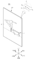
도 1에 도시된 바와 같이, 디스플레이 장치(100)는 영상을 표시하기 위한 복수의 부품들을 수용하는 캐비닛(101)와, 캐비닛(101)의 일측에 마련되어 영상(I)을 표시하는 스크린(S)을 포함할 수 있다.As shown in FIG. 1, the
캐비닛(101)는 디스플레이 장치(100)의 외형을 형성하며, 캐비닛(101)의 내부에는 디스플레이 장치(100)가 영상(I)을 표시하기 위한 부품이 마련될 수 있다. 도 1에 도시된 캐비닛(101)는 평평한 판 형상이나, 캐비닛(101)의 형상이 도 1에 도시된 바에 한정되는 것은 아니다. 예를 들어, 캐비닛(101)는 좌우 양단이 전방으로 돌출되고 중심부가 오목하도록 휘어진 형상일 수 있다.The
스크린(S)은 캐비닛(101)의 전면에 형성되며, 스크린(S)에는 시각 정보인 영상(I)이 표시될 수 있다. 예를 들어, 스크린(S)에는 정지 영상 또는 동영상을 표시될 수 있으며, 2차원 평면 영상 또는 3차원 입체 영상이 표시될 수 있다.The screen S may be formed on the front surface of the
스크린(S)에는 복수의 픽셀들(P)이 형성되며, 스크린(S)에 표시되는 영상(I)은 복수의 픽셀들(P)로부터 출사된 광의 조합에 의하여 형성될 수 있다. 예를 들어, 복수의 픽셀들(P)이 방출하는 광이 모자이크(mosaic)와 같이 조합됨으로써 스크린(S) 상에 하나의 영상(I)이 형성될 수 있다.A plurality of pixels P are formed on the screen S, and the image I displayed on the screen S may be formed by a combination of light emitted from the plurality of pixels P. For example, one image I may be formed on the screen S by combining the light emitted from the plurality of pixels P into a mosaic.
복수의 픽셀들(P) 각각은 다양한 밝기 및 다양한 색상의 광을 방출할 수 있다. 다양한 밝기의 광을 방출하기 위하여, 복수의 픽셀들(P) 각각은 예를 들어 직접 광을 방출할 수 있는 구성(예를 들어, 유기 발광 다이오드)을 포함하거나 백 라이트 유닛 등에 의하여 방출된 광을 투과하거나 차단할 수 있는 구성(예를 들어, 액정 패널)을 포함할 수 있다.Each of the plurality of pixels P may emit light of various brightness and various colors. In order to emit light of varying brightness, each of the plurality of pixels P comprises a configuration (e.g., an organic light emitting diode) capable of emitting light directly, for example, or emits light emitted by a backlight unit or the like. It may include a configuration (eg, a liquid crystal panel) that can transmit or block.
다양한 색상의 광을 방출하기 위하여, 복수의 픽셀들(P) 각각은 서브 픽셀들(PR, PG, PB)을 포함할 수 있다.In order to emit light of various colors, each of the plurality of pixels P may include subpixels P R , P G , and P B.
서브 픽셀들(PR, PG, PB)은 적색 광을 방출할 수 있는 적색 서브 픽셀(PR)과, 녹색 광을 방출할 수 있는 녹색 서브 픽셀(PG)과, 청색 광을 방출할 수 있는 청색 서브 픽셀(PB)을 포함할 수 있다. 예를 들어, 적색 서브 픽셀(PR)은 파장이 대략 620nm (nanometer, 10억분의 1미터)에서 750nm까지의 적색 광을 방출할 수 있고, 녹색 서브 픽셀(PG)은 파장이 대략 495nm에서 570nm까지의 녹색 광을 방출할 수 있으며, 청색 서브 픽셀(PB)은 파장이 대략 450nm에서 495nm까지의 청색 광을 방출할 수 있다..The sub pixels P R , P G and P B emit red light P R that can emit red light, green sub pixel P G that can emit green light, and blue light. It may include a blue sub-pixel (P B ). For example, the red subpixel P R can emit red light from wavelengths of approximately 620 nm (nanometer, 1 billionth of a meter) to 750 nm, and the green sub pixel P G has a wavelength of approximately 495 nm. The green light may emit up to 570 nm, and the blue sub-pixel P B may emit blue light having a wavelength of approximately 450 nm to 495 nm.
적색 서브 픽셀(PR)의 적색 광, 녹색 서브 픽셀(PG)의 녹색 광 및 청색 서브 픽셀(PB)의 청색 광의 조합에 의하여, 복수의 픽셀들(P) 각각은 다양한 밝기와 다양한 색상의 광을 출사할 수 있다.By the combination of the red light of the red sub-pixel P R , the green light of the green sub-pixel P G , and the blue light of the blue sub-pixel P B , each of the plurality of pixels P has various brightnesses and various colors. Can emit light.
도 1에 도시된 스크린(S)은 평평한 판 형상이나, 스크린(S)의 형상이 도 1에 도시된 바에 한정되는 것은 아니다. 예를 들어, 캐비닛(101)의 형상에 따라 스크린(S)은 좌우 양단이 전방으로 돌출되고 중심부가 오목하도록 휘어진 형상일 수 있다.The screen S shown in FIG. 1 has a flat plate shape, but the shape of the screen S is not limited to that shown in FIG. 1. For example, according to the shape of the
디스플레이 장치(100)는 영상을 표시하기 위한 다양한 형태의 디스플레이 패널을 포함할 수 있다. 예를 들어, 디스플레이 장치(100)는 스스로 광을 방출하는 소자를 이용하여 영상을 표시하는 자발광 디스플레이를 포함할 수 있다. 자발광 디스플레이는 발광 다이오드 모듈(Light Emitting Diode Module, LED Module) 또는 유기 발광 다이오드 패널(Organic Light Emitting Diode Panel, OLED Panel) 등이 있다. 또한, 디스플레이 장치(100)는 광원(백라이트 유닛)으로부터 방출된 광을 통과 또는 차단하여 영상을 표시하는 비자발광 디스플레이를 포함할 수 있다. 비자발광 디스플레이는 액정 디스플레이 패널(Liquid Crystal Display Panel, LCD Panel) 등이 있다.The
이하에서는 발광 다이오드 모듈을 포함하는 디스플레이 장치(100)가 설명된다.Hereinafter, the
도 2는 일 실시예에 의한 디스플레이 장치의 정면의 일 예를 도시한다. 도 3은 일 실시예에 의한 디스플레이 장치의 후면의 일 예를 도시한다. 도 4는 일 실시예에 의한 디스플레이 장치의 분해도의 일 예를 도시한다.2 illustrates an example of a front surface of a display apparatus according to an exemplary embodiment. 3 illustrates an example of a rear surface of a display apparatus according to an embodiment. 4 illustrates an example of an exploded view of a display apparatus according to an exemplary embodiment.
도 2, 도 3 및 도 4에 도시된 바에 의하면, 캐비닛(101)의 내부에는 스크린(S)에 영상(I)을 표시하기 위한 각종 구성 부품들이 마련될 수 있다.2, 3 and 4, various components for displaying an image I on the screen S may be provided in the
디스플레이 장치(100)는 전방을 향하여 광을 방출하여 영상을 생성하는 발광 다이오드 모듈(104)과, 발광 다이오드 모듈(104)의 동작을 제어하는 구성이 실장된 제어 어셈블리(106)와, 발광 다이오드 모듈(104) 및 제어 어셈블리(106)에 전원을 공급하는 구성이 실장된 전원 어셈블리(107)와, 제어 어셈블리(106) 및 전원 어셈블리(107)를 지지/고정하는 샤시(105)를 포함한다.The
디스플레이 장치(100)의 전면에는 발광 다이오드 모듈들(104-1, 104-2, 104-3, 104-4, 104-5, 104-6)이 마련될 수 있다. 도 2, 도 3 및 도 4에는 2X3으로 배열된 발광 다이오드 모듈들(104-1, 104-2, 104-3, 104-4, 104-5, 104-6)로 구성된 디스플레이 장치(100)가 도시되었으나, 이에 한정되는 것은 아니며 발광 다이오드 모듈들의 개수 및 배치는 다양하게 변형될 수 있다.Light emitting diode modules 104-1, 104-2, 104-3, 104-4, 104-5, and 104-6 may be provided on the front surface of the
발광 다이오드 모듈(104-1, 104-2, 104-3, 104-4, 104-5, 104-6: 104)은 모듈 기판(104c)에 놓여진 복수의 발광 다이오드 소자들(200)을 포함할 수 있으며, 복수의 발광 다이오드 소자들(200)은 예를 들어 매트릭스 형태로 배치될 수 있다. 또한, 복수의 발광 다이오드 소자들(200)은 각각 발광 다이오드를 포함할 수 있다. 발광 다이오드는 전력이 공급되면 미리 정해진 파장의 광을 방출하는 반도체 소자를 나타낸다. 발광 다이오드는 일반 다이오드와 마찬가지로 극성을 가지며, 캐소드(음극)와 애노드(양극) 사이에 전압이 인가되면 발광 다이오드를 통과하는 전류가 흐르고, 광을 방출한다.The light emitting diode module 104-1, 104-2, 104-3, 104-4, 104-5, 104-6: 104 may include a plurality of light emitting
복수의 발광 다이오드 소자들(200)은 각각 다양한 색상 및 다양한 밝기의 광을 방출할 수 있다. 복수의 발광 다이오드 소자들(200) 각각에 포함된 발광 다이오드는 구성 소재에 따라 서로 다른 파장(서로 다른 색상)을 가지는 광을 방출할 수 있다. 예를 들어, 알루미늄 갈륨 비소(AlGaAs), 갈륨 비소 인(GaAsP) 및 인화 갈륨(GaP) 등을 포함하는 발광 다이오드는 대략 620nm에서 750nm까지의 적색 광을 방출할 수 있으며, 인듐 질화 갈륨(InGaN)를 포함하는 발광 다이오드는 파장이 대략 495nm에서 570nm까지의 녹색 광을 방출할 수 있으며, 질화 갈륨(GaN)을 포함하는 발광 다이오드는 파장이 대략 450nm에서 495nm까지의 청색 광을 방출할 수 있다.The plurality of light emitting
복수의 발광 다이오드 소자들(200)은 적색 서브 픽셀(PR)을 구현하는 적색 발광 다이오드 소자와, 녹색 서브 픽셀(PG)을 구현하는 녹색 발광 다이오드 소자와, 청색 서브 픽셀(PB)을 구현하는 청색 발광 다이오드 소자를 포함할 수 있다. 적색 발광 다이오드 소자와 녹색 발광 다이오드 소자와 청색 발광 다이오드 소자는 일체로 하나의 픽셀(P)을 구현하고, 반복적으로 배열될 수 있다.The plurality of light emitting
또한, 복수의 발광 다이오드 소자들(200)은 공급되는 전류의 크기에 따라 서로 다른 세기의 광을 방출할 수 있다. 복수의 발광 다이오드 소자들(200) 각각에 포함된 발광 다이오드는 공급되는 구동 전류가 증가할수록 강한 세기의 광을 방출할 수 있다.In addition, the plurality of
복수의 발광 다이오드 소자들(200) 각각으로부터 방출되는 광의 조합에 의하여 영상이 형성될 수 있다. 예를 들어, 적색 발광 다이오드로부터 방출되는 적색 광, 녹색 발광 다이오드로부터 방출되는 녹색 광, 청색 발광 다이오드로부터 방출되는 청색 광의 조합에 의하여 영상이 형성될 수 있다.An image may be formed by a combination of light emitted from each of the plurality of light emitting
발광 다이오드 모듈(104)은 앞서 설명된 디스플레이 장치(100)의 스크린(S)을 형성할 수 있으며, 복수의 발광 다이오드 소자들(200) 각각은 앞서 설명된 픽셀들(P) 또는 서브 픽셀(PR, PG, PB)을 형성할 수 있다.The light emitting
스크린(S)은 하나의 발광 다이오드 모듈(140) 또는 복수의 발광 다이오드 모듈들(104-1, 104-2, 104-3, 104-4, 104-5, 104-6)의 집합으로 구현될 수 있으며, 복수의 발광 다이오드 모듈들(104-1, 104-2, 104-3, 104-4, 104-5, 104-6)은 M*N 매트릭스 형태로 배열될 수 있다.The screen S may be implemented as one light emitting
제어 어셈블리(106)는 발광 다이오드 모듈(104)의 동작을 제어하는 제어 회로를 포함할 수 있다. 제어 회로는 외부 컨텐츠 소스로부터 수신된 영상 데이터를 처리하고, 복수의 발광 다이오드 소자들(200)이 서로 다른 색상 및 서로 다른 밝기를 가지는 광을 방출하도록 발광 다이오드 모듈(104)에 영상 데이터를 전송할 수 있다.The
전원 어셈블리(107)는 복수의 발광 다이오드 소자들(200)이 서로 다른 색상 및 서로 다른 밝기를 가지는 광을 방출하도록 발광 다이오드 모듈(104)에 전력을 공급할 수 있다.The
제어 어셈블리(106)와 전원 어셈블리(107)는 인쇄 회로 기판과 인쇄 회로 기판에 실장된 각종 회로로 구현될 수 있다. 예를 들어, 전원 회로는 콘덴서, 코일, 저항 소자, 마이크로 프로세서 등 및 이들이 실장된 전원 회로 기판을 포함할 수 있다. 또한, 제어 회로는 메모리, 마이크로 프로세서 및 이들이 실장된 제어 회로 기판을 포함할 수 있다.The
캐비닛(101)은 프런트 브라켓(101a)과 프레임 브라켓(102)과 후면 커버(103)를 포함할 수 있으며, 프런트 브라켓(101a)과 프레임 브라켓(102)과 후면 커버(103)는 내부의 발광 다이오드 모듈(104), 제어 어셈블리(106) 및 전원 어셈블리(107)를 지지 및 수용할 수 있다. The
프런트 브라켓(101a)은 발광 다이오드 모듈(104)을 지지할 수 있다. 프레임 브라켓(102)은 프런트 브라켓(101a)의 배면에 위치하며, 제어 어셈블리(106) 및 전원 어셈블리(107)를 수용할 수 있다. 후면 커버(103)는 프레임 브라켓(102)의 배면을 개폐할 수 있다.The
샤시(105)는 제어 어셈블리(106) 및 전원 어셈블리(107)를 지지할 수 있다. 예를 들어, 제어 어셈블리(106)와 전원 어셈블리(107)는 샤시(105)에 고정되고, 샤시(105)는 캐비닛(101)에 고정될 수 있다.The
도 5는 일 실시예에 의한 디스플레이 장치에 포함된 발광 다이오드 소자의 일 예를 도시한다.5 illustrates an example of a light emitting diode device included in a display device according to an embodiment.
도 5에 도시된 바에 의하면, 발광 다이오드 소자(200)는 LED 패키지 기판(210)과, 사파이어 기판(220)과, n타입 반도체 층(230)과, n타입 패드(240)와, p타입 반도체 층(250)과, p타입 패드(260)를 포함할 수 있다.As shown in FIG. 5, the
발광 다이오드 소자(200)는 사파이어 기판(220)에 n타입 반도체 층(230)을 성장시키시고, 이후 p타입 반도체 층(250)을 성장시킴으로써 제조될 수 있다.The light emitting
사파이어 기판(220)은 n타입 반도체 층(230)과 p타입 반도체 층(250)을 성장시키기 위한 기저로서 기능한다. 알루미나(A12O3)를 고온에서 녹인 이후 서서히 냉각함으로써 단결정 사파이어 기판(220)이 제조될 수 있다.The
n타입 반도체 층(230)은 자유 전자가 전하(전기)를 전달하는 반도체를 의미한다. n타입 반도체 층(230)은 반도체를 형성하는 기본 물질(예를 들어, Si, GaAs, GaN 등)에 도너(donor) 물질이 추가됨으로써 제조될 수 있다. 구체적으로, 사파이어 기판(220)이 놓여진 챔버 내에 반도체 기본 물질과 도너 물질이 함께 주입됨으로, 사파이어 기판(220) 상에 n타입 반도체 층(230)이 성장될 수 있다.The n-
p타입 반도체 층(250)은 정공이 전하(전기)를 전달하는 반도체를 의미한다. p타입 반도체 층(250)은 반도체를 형성하는 기본 물질(예를 들어, Si, GaAs, GaN 등)에 억셉터(acceptor) 물질이 추가됨으로써 제조될 수 있다. 구체적으로, n타입 반도체 층(230)이 형성된 사파이어 기판(220)이 놓여진 챔버 내에 반도체 기본 물질과 억셉터 물질이 함께 주입됨으로, n타입 반도체 층(230) 상에 p타입 반도체 층(250)이 성장될 수 있다.The p-
n타입 반도체 층(230)과 p타입 반도체 층(250)의 경계에는 공핍 층(depletion region) (270)이 형성되며, 공핍 층(270)에서의 자유 전자와 정공의 결합에 의하여 광이 발생될 수 있다. 공핍 층(270)에서 발생되는 광의 주파수(광의 색상)은 반도체 물질의 에너지 밴드 갭(energy band gap)에 의존하며, 광의 세기는 발광 다이오드 소자(200)에 공급되는 전류에 의존할 수 있다.A
n타입 패드(240)는 n타입 반도체 층(230)과 아래에서 설명할 와이어(104a, 104b)를 연결할 수 있다. n타입 패드(240)에는 높은 농도의 도너 물질이 주입되며, 그에 따라서 n타입 패드(240)는 높은 전기 전도성을 갖으며, 와이어(104a, 104b)와 접촉 시에 매우 낮은 전기 저항을 갖는다. n타입 패드(240)는 이온 주입(ion implantation)을 이용하여 n타입 반도체 층(230)에 도너 물질을 주입하거나, 높은 농도의 도너 물질과 함께 반도체 층을 성장시킴으로써 형성될 수 있다. n타입 패드(240)는 발광 다이오드 소자(200)의 음극(cathode) 단자에 해당한다.The n-
p타입 패드(260)는 n타입 반도체 층(230)과 아래에서 설명할 와이어(104a, 104b)를 연결할 수 있다. n타입 패드(240)에는 높은 농도의 도너 물질이 주입되며, 그에 따라서 n타입 패드(240)는 높은 전기 전도성을 갖으며, 와이어(104a, 104b)와 접촉 시에 매우 낮은 전기 저항을 갖는다. n타입 패드(240)는 이온 주입(ion implantation)을 이용하여 n타입 반도체 층(230)에 도너 물질을 주입하거나, 높은 농도의 도너 물질과 함께 반도체 층을 성장시킴으로써 형성될 수 있다. p타입 패드(260)는 발광 다이오드 소자(200)의 양극(anode) 단자에 해당한다.The p-
이와 같은 방식으로 발광 다이오드 칩이 제작되며, 발광 다이오드 칩은 LED 패키지 기판(210) 상에 놓여져 발광 다이오드 소자(발광 다이오드 패키지) (200)가 제작된다.In this manner, a light emitting diode chip is manufactured, and the light emitting diode chip is placed on the
이후, 발광 다이오드 소자(200)는 발광 다이오드 모듈(104)을 형성하는 모듈 기판(104c) 상에 놓여지며, 발광 다이오드 소자(200)와 모듈 기판(104c)은 와이어(104a, 104b)에 의하여 전기적으로 연결될 수 있다.Thereafter, the light emitting
와이어(104a, 104b)는 p타입 패드(260) (발광 다이오드 소자의 양극)와 모듈 기판(104c)을 연결하는 양의 와이어(104a)와, n타입 패드(240) (발광 다이오드 소자의 양극)와 모듈 기판(104c)을 연결하는 음의 와이어(104b)를 포함할 수 있다.The
와이어(104a, 104b)는 신호의 손실을 최소화하기 위하여 높은 전기 전도성을 갖는 금(Au) 등으로 구성될 수 있다.The
이와 같은 방식으로 발광 다이오드 소자(200)가 모듈 기판(104c) 상에 실장되어 발광 다이오드 모듈(104)이 제작될 수 있다.In this manner, the light emitting
또한, 발광 다이오드 소자(200)를 보호하기 위하여 발광 다이오드 모듈(104)의 전면(발광 다이오드 소자가 설치된 면)에 에폭시 수지(epoxy resin) (104d)가 코팅될 수 있다.In addition, an
이와 같이, 발광 다이오드 모듈(104)에 포함된 발광 다이오드 소자(200)는 에폭시 수지(104d)에 의하여 보호될 수 있다.As such, the
그러나, 에폭시 수지(104d)가 코딩되었더라도, 수증기는 에폭시 수지(104d)를 통과하여 발광 다이오드 소자(200)까지 침투할 수 있다. 예를 들어, 발광 다이오드 모듈(104)이 고온 다습한 환경에 놓여진 경우, 수증기가 에폭시 수지(104d)를 통과하여 발광 다이오드 소자(200)까지 침투할 수 있다.However, even if the
발광 다이오드 소자(200)까지 침투한 수증기는 발광 다이오드 소자(200)가 냉각되면 응결되며, 그에 따라서 발광 다이오드 소자(200)에 물방울이 형성될 수 있다.Water vapor that penetrates to the light emitting
이처럼 수증기가 응결되어 생성된 물방울(수분)에 의하여 와이어(104a, 104b)의 이온화가 발생할 수 있다. 다시 말해, p타입 패드(260)에 접촉된 와이어(104a, 104b)가 이온화에 의하여 n타입 반도체 층(230)까지 확장될 수 있다. 그 결과, p타입 반도체 층(250)과 n타입 반도체 층(230) 사이의 전기적 단락이 발생하며, 발광 다이오드 소자(200) 및 발광 다이오드 모듈(104)이 파손될 수 있다.As such, ionization of the
이를 방지하기 위하여 디스플레이 장치(100)는 주변 온도 및 주변 습도에 따라 발광 다이오드 소자(200)의 온도를 조절하기 위한 구성 또는 주변 온도 및 주변 습도를 조절하기 위한 구성을 포함할 수 있다.To prevent this, the
이하에서는 디스플레이 장치(100)의 구성이 설명된다.Hereinafter, the configuration of the
도 6은 일 실시예에 의한 디스플레이 장치의 구성을 도시한다. 도 7 및 도 8은 일 실시예에 의한 디스플레이 장치에 포함된 발광 다이오드 모듈의 일 예를 도시한다. 도 9는 일 실시예에 의한 디스플레이 장치에 포함된 발광 다이오드 소자와 LED 모듈 온도 센서의 일 예를 도시한다. 도 10은 일 실시예에 의한 디스플레이 장치에 포함된 발광 다이오드 모듈과 LED 히터의 일 예를 도시한다. 도 11는 일 실시예에 의한 디스플레이 장치가 외부 장치와 통신하는 일 예를 도시한다.6 illustrates a configuration of a display apparatus according to an embodiment. 7 and 8 illustrate an example of a light emitting diode module included in a display device according to an embodiment. 9 illustrates an example of a light emitting diode device and an LED module temperature sensor included in a display device according to an embodiment. 10 illustrates an example of a light emitting diode module and an LED heater included in a display device according to an embodiment. 11 illustrates an example in which the display apparatus communicates with an external device, according to an exemplary embodiment.
도 6, 도 7, 도 8, 도 9, 도 10, 및 도 11에 도시된 바에 의하면, 디스플레이 장치(100)는 사용자로부터 사용자 입력을 수신하는 사용자 입력부(110)와, 컨텐츠 소스들로부터 비디오 신호 및/또는 오디오 신호를 수신하는 컨텐츠 수신부(120)와, 영상을 표시하는 영상 표시부(130)와, 음향을 출력하는 음향 출력부(140)와, 디스플레이 장치(100)의 주변 환경 정보를 수집하는 환경 감지부(150)와, 발광 다이오드 모듈(104)의 온도를 측정하는 LED 모듈 온도 센서(155)와, 발광 다이오드 모듈(104)에서의 수증기 응결을 방지하는 온도 조절부(160)와, 외부 장치들(10, 20)와 통신하는 통신부(170)와, 각종 프로그램 및 데이터를 저장하는 데이터 저장부(180)와, 디스플레이 장치(100)의 동작을 제어하는 제어부(190)를 포함한다.6, 7, 8, 9, 10, and 11, the
사용자 입력부(110)는 사용자 입력을 수신하는 입력 버튼(111)를 포함할 수 있다. 예를 들어, 사용자 입력부(110)는 디스플레이 장치(100)를 소프트 턴온(동작 개시) 또는 소프트 턴오프(동작 종료)시키기 위한 전원 버튼, 디스플레이 장치(100)가 출력하는 음향의 볼륨을 조절하기 위한 음향 조절 버튼, 컨텐츠 소스를 선택하기 위한 소스 선택 버튼 등을 포함할 수 있다.The
입력 버튼(111)는 각각 사용자 입력을 수신하고 사용자 입력에 대응하는 전기적 신호를 제어부(300)로 출력할 수 있으며, 푸시 스위치, 터치 스위치, 다이얼, 슬라이드 스위치, 토글 스위치 등 다양한 입력 수단에 의하여 구현될 수 있다.The
사용자 입력부(110)는 또한 리모트 컨트롤러의 원격 제어 신호를 수신하는 신호 수신기(112)를 포함한다. 사용자 입력을 수신하는 리모트 컨트롤러는 디스플레이 장치(100)와 분리되어 마련될 수 있으며, 사용자 입력을 수신하고, 사용자 입력에 대응하는 무선 신호를 디스플레이 장치(100)로 전송할 수 있다. 신호 수신기(112)는 리모트 컨트롤러로부터 사용자 입력에 대응하는 무선 신호를 수신하고, 사용자 입력에 대응하는 전기적 신호를 제어부(190)로 출력할 수 있다.The
컨텐츠 수신부(120)는 컨텐츠 소스들로부터 비디오 신호 및/또는 오디오 신호를 포함하는 컨텐츠를 수신하는 수신 단자(121) 및 튜너(122)를 포함할 수 있다.The
수신 단자(121)은 케이블을 통하여 컨텐츠 소스들로부터 비디오 신호와 오디오 신호를 수신할 수 있다. 예를 들어, 수신 단자(121)은 컴포넌트(component, YPbPr/RGB) 단자, 컴포지트 (composite video blanking and sync, CVBS) 단자, 오디오 단자, 고화질 멀티미디어 인터페이스 (High Definition Multimedia Interface, HDMI) 단자, 범용 직렬 버스(Universal Serial Bus, USB) 단자 등을 포함할 수 있다.The receiving
튜너(122)는 방송 수신 안테나 또는 유선 케이블로부터 방송 신호를 수신하고, 방송 신호 중에 사용자에 의하여 선택된 채널의 방송 신호를 추출할 수 있다. 예를 들어, 튜너(122)는 방송 수신 안테나 또는 유선 케이블을 통하여 수신된 복수의 방송 신호 중에 사용자에 의하여 선택된 채널에 해당하는 주파수를 가지는 방송 신호를 통과시키고, 다른 주파수를 가지는 방송 신호를 차단할 수 있다.The
이처럼, 컨텐츠 수신부(120)는 수신 단자(121) 및/또는 튜너(122)를 통하여 컨텐츠 소스들로부터 비디오 신호와 오디오 신호를 수신할 수 있으며, 수신 단자(121) 및/또는 튜너(122)를 통하여 수신된 비디오 신호 및/또는 오디오 신호를 제어부(190)로 출력할 수 있다.As such, the
영상 표시부(130)는 영상을 시각적으로 표시하는 발광 다이오드 모듈(104)과, 발광 다이오드 모듈(104)을 구동하는 LED 드라이버(131)를 포함한다.The
LED 드라이버(131)는 제어부(190)로부터 영상 데이터를 수신하고, 수신된 영상 데이터에 대응하는 영상을 표시하도록 발광 다이오드 모듈(104)을 구동할 수 있다. 예를 들어, LED 드라이버(131)는 발광 다이오드 모듈(104)에 영상을 표시하기 위한 영상 신호를 출력할 수 있다.The
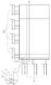
도 7에 도시된 바와 같이, LED 드라이버(131)는 데이터 드라이버(131a)와 스캔 드라이버(131b)를 포함할 수 있다.As shown in FIG. 7, the
데이터 드라이버(131a)는 제어부(190)로부터 적색/녹색/청색 영상 데이터(이하 'RGB 영상 데이터'라 한다)와 데이터 제어 신호를 수신하고, 데이터 제어 신호에 따라 RGB 영상 데이터를 발광 다이오드 모듈(104)로 출력할 수 있다. 구체적으로 데이터 드라이버(131a)는 디지털 RGB 영상 데이터를 수신하고, 디지털 RGB 영상 데이터를 아날로그 RGB 영상 신호로 변환하고, 아날로그 RGB 영상 신호를 발광 다이오드 모듈(104)로 출력할 수 있다.The
데이터 드라이버(131a)에 구비된 복수의 출력들은 각각 발광 다이오드 모듈(104)의 복수의 데이터 라인들(D1, D2, D3)과 연결될 수 있으며, 데이터 드라이버(131a)는 복수의 데이터 라인들(D1, D2, D3)을 통하여 발광 다이오드 모듈(104)에 포함된 복수의 발광 다이오드 소자들(200) 각각으로 RGB 영상 신호를 출력할 수 있다. 예를 들어, 데이터 드라이버(131a)는 발광 다이오드 모듈(104) 상에서 하나의 행(row)에 포함된 복수의 발광 다이오드 소자들(200) 각각으로 RGB 영상 신호를 동시에 출력할 수 있다.The plurality of outputs included in the
스캔 드라이버(131b)는 제어부(190)로부터 스캔 제어 신호를 수신하고, 스캔 제어 신호에 따라 복수의 행들(row) 중에 어느 하나의 행에 포함된 복수의 발광 다이오드 소자들(200)을 활성화할 수 있다. 예를 들어, 스캔 드라이버(131b)는 스캔 제어 신호에 따라 복수의 스캔 라인들(S1, S2) 중에 어느 하나에 활성화 신호를 출력할 수 있다.The
스캔 드라이버(131b)는 스캔 제어 신호에 따라 매트릭스 형태로 배치된 복수의 발광 다이오드 소자들(200) 중에 적절한 행(row)에 속하는 발광 다이오드 소자들(200)에 RGB 영상 신호가 제공되도록 복수의 스캔 라인들(S1, S2) 중 어느 하나를 선택할 수 있다. 또한, 데이터 드라이버(131a)는 복수의 데이터 라인들(D1, D2, D3)을 통하여 RGB 영상 신호를 출력할 수 있으며, 데이터 드라이버(131a)에 의하여 출력된 RGB 영상 신호는 스캔 드라이버(131b)에 의하여 선택된 행(row)에 속하는 발광 다이오드 소자들(200)에 제공될 수 있다.The
이처럼, 데이터 드라이버(131a)와 스캔 드라이버(131b)는 발광 다이오드 모듈(104)에 포함된 복수의 발광 다이오드 소자들(200)에 순차적으로 RGB 영상 신호를 제공할 수 있다.As such, the
발광 다이오드 모듈(104)은 LED 드라이버(131)로부터 수신된 영상 데이터에 따라 영상을 생성하고, 영상을 표시할 수 있다.The
도 8에 도시된 바와 같이, 발광 다이오드 모듈(104)은 복수의 픽셀들(P)을 포함할 수 있으며, 복수의 픽셀들(P) 각각은 적색 서브 픽셀(PR)과 녹색 서브 픽셀(PG)과 청색 서브 픽셀(PB)을 포함할 수 있다.As shown in FIG. 8, the light emitting
복수의 서브 픽셀들(PR, PG, PB) 각각은 발광 다이오드 소자(200)를 포함할 수 있다. 예를 들어, 적색 서브 픽셀(PR)은 적색 광을 방출하는 적색 발광 다이오드 소자(200r)를 포함하며, 녹색 서브 픽셀(PG)은 녹색 광을 방출하는 녹색 발광 다이오드 소자(200g)를 포함하며, 청색 서브 픽셀(PB)은 청색 광을 방출하는 청색 발광 다이오드 소자(200b)를 포함할 수 있다. 적색 발광 다이오드 소자(200r)와 녹색 발광 다이오드 소자(200g)와 청색 발광 다이오드 소자(200b)는 일체로 하나의 발광 다이오드 소자를 구성하거나, 각각이 별개의 발광 다이오드 소자를 구성할 수 있다. Each of the plurality of subpixels P R , P G , and P B may include a light emitting
복수의 발광 다이오드 소자들(200)은 발광 다이오드 모듈(104) 상에 2차원으로 배치될 수 있다. 예를 들어, 복수의 발광 다이오드 소자들(200)은 발광 다이오드 모듈(104) 상에 행렬(matrix)을 이루어 배치될 수 있다. 다시 말해, 복수의 발광 다이오드 소자들(200)은 행(row)와 열(column)로 배치될 수 있다.The plurality of light emitting
복수의 발광 다이오드 소자들(200) 사이에는 복수의 데이터 라인들(D1, D2, D3)과, 복수의 스캔 라인들(S1, S2)이 마련될 수 있다. 복수의 스캔 라인들(S1, S2)과 복수의 데이터 라인들(D1, D2, D3)은 LED 드라이버(131)와 연결될 수 있다.A plurality of data lines D 1 , D 2 , and D 3 and a plurality of scan lines S 1 and S 2 may be provided between the plurality of
발광 다이오드 모듈(104)의 적색 발광 다이오드 소자(200r)와 녹색 발광 다이오드 소자(200g)와 청색 발광 다이오드 소자(200b) 각각은 각각 데이터 드라이버(131a)로부터 RGB 영상 신호를 수신할 수 있다.Each of the red light emitting
적색 발광 다이오드 소자(200r)와 녹색 발광 다이오드 소자(200g)와 청색 발광 다이오드 소자(200b) 각각은 데이터 드라이버(131a)로부터 출력되는 RGB 영상 신호에 따라 서로 다른 세기의 광을 출력할 수 있다. 또한, 적색 발광 다이오드 소자(200r)와 녹색 발광 다이오드 소자(200g)와 청색 발광 다이오드 소자(200b) 각각은 서로 다른 파장(서로 다른 색상)을 가지는 광을 방출할 수 있다.Each of the red light emitting
음향 출력부(140)는 음향을 청각 신호(음파)로 출력하는 스피커(141)를 포함한다.The
스피커(141)는 앰프에 의하여 증폭된 아날로그 음향 신호를 음향(음파)으로 변환할 수 있다. 예를 들어, 스피커(141)는 전기적 음향 신호에 따라 진동하는 박막을 포함할 수 있으며, 박막의 진동에 의하여 음파가 생성될 수 있다.The
환경 감지부(150)는 발광 다이오드 모듈(104)의 주변 온도를 감지하는 주변 온도 센서(ambient temperature sensor) (151)와, 발광 다이오드 모듈(104)의 주변 습도를 감지하는 주변 습도 센서(ambient humidity sensor) (152)를 포함할 수 있다.The
주변 온도 센서(151)는 발광 다이오드 모듈(104)의 주변 온도를 측정할 수 있으며, 디스플레이 장치(100)의 캐비닛(101)의 내부 또는 캐비닛(101)의 외부에 설치될 수 있다.The
주변 온도 센서(151)는 발광 다이오드 모듈(104)의 주변 온도에 대응하는 전기적 신호를 제어부(190)로 전달할 수 있다. 예를 들어, 주변 온도 센서(151)는 주변 온도에 따라 전기적 저항 값이 변화할 수 있다.The
주변 습도 센서(152)는 발광 다이오드 모듈(104)의 주변 습도를 측정할 수 있으며, 디스플레이 장치(100)의 캐비닛(101)의 내부 또는 캐비닛(101)의 외부에 설치될 수 있다.The
주변 습도 센서(152)는 발광 다이오드 모듈(104)의 주변 습도에 대응하는 전기적 신호를 제어부(190)로 전달할 수 있다. 예를 들어, 주변 습도 센서(152)는 주변 습도에 따라 전기적 저항 값이 변화하거나 주변 습도에 따라 정전 용량이 변화할 수 있다.The
LED 모듈 온도 센서(155)는 발광 다이오드 모듈(104)의 온도를 측정할 수 있으며, 발광 다이오드 모듈(104)의 발광 다이오드 소자(200) 및/또는 모듈 기판(104c)에 설치될 수 있다.The LED
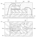
예를 들어, 도 9의 (a)에 도시된 바와 같이 LED 모듈 온도 센서(155)는 발광 다이오드 소자(200)의 p타입 패드(260) 주변에 설치될 수 있다. 또한, LED 모듈 온도 센서(155)는 발광 다이오드 소자(200)의 온도에 대응하는 전기적 신호를 제어부(190)로 전달할 수 있으며, 제어부(190)는 LED 모듈 온도 센서(155)의 전기적 신호에 기초하여 발광 다이오드 모듈(104)의 온도를 식별할 수 있다.For example, as illustrated in FIG. 9A, the LED
다른 예로, 도 9의 (b)에 도시된 바와 같이 LED 모듈 온도 센서(155)는 모듈 기판(104c) 상에 설치될 수 있다. 또한, LED 모듈 온도 센서(155)는 모듈 기판(104c)의 온도에 대응하는 전기적 신호를 제어부(190)로 전달할 수 있으며, 제어부(190)는 LED 모듈 온도 센서(155)의 전기적 신호에 기초하여 발광 다이오드 모듈(104)의 온도를 식별할 수 있다.As another example, as shown in FIG. 9B, the LED
온도 조절부(160)는 발광 다이오드 모듈(104)을 가열하는 히터(161)와, 발광 다이오드 모듈(104) 주변의 공기를 순환시키는 팬(162)을 포함하며, 온도 조절부(160) 또한 제어부(190)의 제어 신호에 따라 히터(161)와 팬(162)을 제어할 수 있다.The
히터(161)는 발광 다이오드 모듈(104) 및/또는 발광 다이오드 소자(200)를 가열할 수 있다. 발광 다이오드 모듈(104) 및/또는 발광 다이오드 소자(200)가 가열됨으로 인하여, 발광 다이오드 모듈(104) 및/또는 발광 다이오드 소자(200)에서의 수증기의 응결이 방지될 수 있다.The
예를 들어, 히터(161)는 전류의 흐름에 의하여 발열할 수 있다. 도 10에 도시된 바와 같이 히터(161)는 발광 다이오드 모듈(104) 상의 발광 다이오드 소자(200) 근방에 위치할 수 있으며, 히터(161)는 발광 다이오드 소자(200)를 가열하고, 그에 따라서 발광 다이오드 소자(200)의 온도가 상승할 수 있다.For example, the
팬(162)은 발광 다이오드 모듈(104) 및/또는 발광 다이오드 소자(200) 주변의 공기를 순환시킬 수 있다. 발광 다이오드 모듈(104) 및/또는 발광 다이오드 소자(200) 주변의 공기가 순환됨으로 인하여, 발광 다이오드 모듈(104) 및/또는 발광 다이오드 소자(200)에서의 수증기의 응결이 방지될 수 있다.The
팬(162)은 발광 다이오드 모듈(104) 근방의 공기가 순환되도록 캐비닛(101) 외부의 공기를 캐비닛(101) 내부로 유입시키거나 캐비닛(101) 내부의 공기를 캐비닛(101) 외부로 유출시킬 수 있다. 그에 따라서, 발광 다이오드 모듈(104) 및/또는 발광 다이오드 소자(200) 상에 수증기가 응결되는 것이 방지되고, 발광 다이오드 모듈(104) 및/또는 발광 다이오드 소자(200) 상에 응결된 물방울은 공기의 순환에 의하여 증발될 수 있다.The
이처럼, 온도 조절부(160)는 제어부(190)의 제어 신호에 응답하여 히터(161) 및/또는 팬(162)을 이용하여 발광 다이오드 모듈(104)의 온도 및/또는 캐비닛(101) 내부의 온도를 조절할 수 있다. 나아가, 온도 조절부(160)는 제어부(190)의 제어 신호에 응답하여 캐비닛(101)의 주변 대기 환경을 조절하도록 하는 제어 신호를 통신부(170)를 통하여 외부 장치들(10, 20)로 전송할 수 있다.As such, the
통신부(170)는 외부 장치들(10, 20)과 데이터를 주고 받을 수 있다. 예를 들어, 도 11에 도시된 바와 같이 통신부(170)는 공기조화기(10) 및/또는 제습기(20) 등과 데이터를 주고 받을 수 있다. 통신부(170)는 공기조화기(10) 및/또는 제습기(20)으로부터 디스플레이 장치(100) 주변의 온도 및/또는 습도 값을 포함하는 신호를 수신하고, 공기조화기(10) 및/또는 제습기(20)로 동작 명령을 포함하는 신호를 송신할 수 있다.The
통신부(170)는 외부 장치들(10, 20)과 유선으로 데이터를 주고받는 유선 통신 모듈(171)과, 외부 장치들(10, 20)과 무선으로 데이터를 주고받는 무선 통신 모듈(172)을 포함할 수 있다.The
유선 통신 모듈(171)은 유선 통신망에 접속하고 유선 통신망을 통하여 공기조화기(10) 및/또는 제습기(20)와 통신할 수 있다. 예를 들어, 유선 통신 모듈(171)은 이더넷(Ethernet, IEEE 802.3 기술 표준)을 통하여 유선 통신망에 접속하고, 유선 통신망을 통하여 공기조화기(10) 및/또는 제습기(20)로부터 데이터를 수신할 수 있다.The wired communication module 171 may be connected to the wired communication network and communicate with the
무선 통신 모듈(172)은 기지국(base station) 또는 액세스 포인트(AP)와 무선으로 통신할 수 있으며, 기지국 또는 액세스 포인트를 통하여 유선 통신망에 접속할 수 있다. 무선 통신 모듈(172)은 또한 기지국 또는 액세스 포인트를 거쳐 유선 통신망에 접속된 공기조화기(10) 및/또는 제습기(20)와 통신할 수 있다. 예를 들어, 무선 통신 모듈(172)은 와이파이(WiFi™, IEEE 802.11 기술 표준)을 이용하여 액세스 포인트(AP)와 무선으로 통신하거나, CDMA, WCDMA, GSM, LET(Long Term Evolution), 와이브로 등을 이용하여 기지국과 통신할 수 있다. 무선 통신 모듈(171)은 또한 기지국 또는 액세스 포인트를 거쳐 공기조화기(10) 및/또는 제습기(20)로부터 데이터를 수신할 수 있다.The
뿐만 아니라, 무선 통신 모듈(172)은 공기조화기(10) 및/또는 제습기(20)와 직접 통신할 수 있다. 예를 들어, 무선 통신 모듈(172)은 와이파이, 블루투스 (Bluetooth™, IEEE 802.15.1 기술 표준), 지그비(ZigBee™, IEEE 802.15.4 기술 표준) 등을 이용하여 공기조화기(10) 및/또는 제습기(20)로부터 무선으로 데이터를 수신할 수 있다.In addition, the
이처럼, 통신부(170)는 공기조화기(10) 및/또는 제습기(20)과 데이터를 주고 받을 수 있으며, 공기조화기(10) 및/또는 제습기(20)로부터 수신된 데이터를 제어부(190)로 출력할 수 있다.As such, the
데이터 저장부(180)는 디스플레이 장치(100)의 동작을 제어하기 위한 프로그램 및 데이터를 저장하는 저장 매체(181)를 포함할 수 있다. 여기서, 프로그램은 특정한 기능을 수행하기 위하여 조합된 복수의 명령어들을 포함하며, 데이터는 프로그램에 포함된 복수의 명령어들에 의하여 처리 및/또는 가공될 수 있다.The
저장 매체(181)는 컨텐츠 데이터를 파일의 형태로 저장할 수 있다. 예를 들어, 저장 매체(181)는 "*.mpg" 또는 "*.avi" 또는 "*.asf" 또는 "*.mp4" 파일의 형태로 컨텐츠 데이터를 저장할 수 있으며, 제어부(190)의 독출(readout) 명령에 응답하여 컨텐츠 데이터를 제어부(190)에 제공할 수 있다.The storage medium 181 may store content data in the form of a file. For example, the storage medium 181 may store content data in the form of a "* .mpg" or "* .avi" or "* .asf" or "* .mp4" file, and the read of the
저장 매체(181)는 환경 감지부(150)에 의하여 수집된 주변 온도 및/또는 주변 습도를 날짜에 따라 저장할 수 있다. 예를 들어, 저장 매체(181)는 주변 온도 및/또는 주변 습도를 포함하는 데이터 베이스(database, DB)를 저장할 수 있으며, 제어부(190)의 독출 명령에 응답하여 데이터 베이스의 정보를 제어부(190)에 제공할 수 있다.The storage medium 181 may store the ambient temperature and / or ambient humidity collected by the
저장 매체(181)는 프로그램 및/또는 데이터를 전기적으로 또는 자기적으로 또는 광학적으로 저장할 수 있다. 예를 들어, 저장 매체(181)는 반도체 소자 드라이브(solid stat driver, SSD) 또는 하드 디스크 드라이브(hard disc drive, HDD) 또는 광 디스크 드라이브(optical disc drive, ODD) 등을 포함할 수 있다.The storage medium 181 can store the program and / or data electrically, magnetically or optically. For example, the storage medium 181 may include a solid state driver (SSD), a hard disc drive (HDD), an optical disc drive (ODD), or the like.
이처럼, 데이터 저장부(180)는 프로그램 및/또는 데이터를 저장할 수 있으며, 제어부(190)의 독출 명령에 응답하여 제어부(190)로 프로그램 및/또는 데이터를 제공할 수 있다.As such, the
제어부(190)는 프로그램 및 데이터를 기억/저장하는 1 또는 2 이상의 메모리(191)와, 프로그램에 따라 데이터를 처리하는 1 또는 2 이상의 프로세서(192)를 포함할 수 있다. 제어부(190)는 프로세서(192) 및 메모리(191) 등의 하드웨어와, 메모리(191) 및/또는 데이터 저장부(180)에 기억/저장된 프로그램 및 데이터 등의 소프트웨어를 포함할 수 있다.The
메모리(191)는 디스플레이 장치(100)에 포함된 구성들을 제어하기 위한 프로그램 및 데이터를 기억/저장할 수 있다. 예를 들어, 메모리(191)는 프로세서(192)에 의하여 실행되는 명령어들을 저장할 수 있다.The
메모리(191)는 디스플레이 장치(100)에 포함된 구성로부터 제공된 데이터들을 임시로 기억할 수 있다. 예를 들어, 메모리(191)는 사용자 입력부(110)로부터 전달된 사용자 입력, 컨텐츠 수신부(120)를 통하여 수신된 영상 데이터, 환경 감지부(150)에 의하여 감지된 주변 온도 및/또는 주변 습도, LED 모듈 온도 센서(155)에 의하여 감지된 발광 다이오드 온도, 통신부(170)를 통하여 수신된 통신 데이터, 데이터 저장부(180)에 저장된 데이터 등을 기억할 수 있다.The
메모리(191)는 데이터를 장기간 저장하기 위한 롬(Read Only Memory), 플래시 메모리(flash memory) 등의 비휘발성 메모리와, 데이터를 일시적으로 기억하기 위한 S-램(Static Random Access Memory, S-RAM), D-램(Dynamic Random Access Memory) 등의 휘발성 메모리를 포함할 수 있다The
프로세서(192)는 메모리(191)에 기억된 프로그램(일련의 프로그램)에 따라 메모리(191)에 기억된 데이터를 처리할 수 있다. 예를 들어, 프로세서(192)는 메모리(191)에 기억/저장된 프로그램에 따라 사용자 입력, 영상 데이터, 주변 온도 및/또는 주변 습도, 발광 다이오드 모듈(104)의 온도, 통신 데이터, 저장 데이터 등을 처리할 수 있다. 또한, 프로세서(192)는 데이터의 처리 결과에 기초하여 영상 표시부(130), 온도 조절부(160), 통신부(170) 및/또는 데이터 저장부(180)를 제어하기 위한 제어 신호를 생성할 수 있다.The
프로세서(192)는 논리 연산 및 산술 연산 등을 수행하는 연산 회로와, 연산된 데이터를 기억하는 기억 회로 등을 포함할 수 있다.The
이처럼, 제어부(190)는 디스플레이 장치(100)에 포함된 구성들로부터 획득된 데이터를 처리하고, 디스플레이 장치(100)에 포함된 구성들을 제정할 수 있다.As such, the
제어부(190)는 사용자 입력부(110)를 통한 사용자 입력에 따라 디스플레이 장치(100)의 동작을 제어할 수 있다. 예를 들어, 제어부(190)는 사용자의 동작 개시(턴온)를 위한 입력에 응답하여 영상 표시부(130)에 전력을 공급하고 영상 표시부(130)에 영상 데이터를 전달할 수 있다. 또한, 제어부(190)는 사용자의 동작 종료(턴오프)를 위한 입력에 응답하여 영상 표시부(130)로 영상 데이터의 전달을 중지하고, 영상 표시부(130)로의 전력 공급을 차단할 수 있다.The
제어부(190)는 컨텐츠 수신부(120)를 통하여 수신되거나 데이터 저장부(180)에 저장된 영상 데이터(영상 프레임 데이터, 텔레비전 방송 신호, 스트리밍 데이터 등)을 처리할 수 있다. 예를 들어, 제어부(190)는 컨텐츠 수신부(120) 및/또는 데이터 저장부(180)로부터 압축/인코딩된 영상 데이터를 획득할 수 있으며, 압축/인코딩된 영상 데이터를 영상 프레임으로 디코딩할 수 있다. 또한, 제어부(190)는 처리된 영상 프레임을 영상 표시부(130)에 제공할 수 있다.The
제어부(190)는 환경 감지부(150)에 의하여 감지된 주변 온도 및/또는 주변 습도에 기초하여 이슬점 온도를 산출하거나, 통신부(170)를 통하여 공기조화기(10) 및/또는 제습기(20)로부터 수신된 주변 온도 및/또는 주변 습도에 기초하여 이슬점 온도를 산출하거나, 데이터 저장부(180)에 저장된 이슬점 온도를 데이터 저장부(180)로부터 획득할 수 있다.The
제어부(190)는 이슬점 온도와 LED 모듈 온도 센서(155)에 의하여 감지된 발광 다이오드 모듈(104)의 온도에 따라, 히터(161) 및/또는 팬(162)을 구동하거나 공기조화기(10) 및/또는 제습기(20)로 동작을 요청하는 신호를 전송하도록 통신부(170)를 제어할 수 있다.The
프로세서(192)와 메모리(191)는 각각 별도의 복수의 반도체 소자들로 구현되거나, 일체로 하나의 반도체 소자로 구현될 수 있다.The
이상에서 설명된 바와 같이, 디스플레이 장치(100)는 주변 온도, 주변 습도 및 발광 다이오드 모듈(104)의 온도를 획득하고, 주변 온도, 주변 습도 및 발광 다이오드 모듈(104)에 따라 온도 조절부(160)를 제어할 수 있다.As described above, the
이하에서는 디스플레이 장치(100)의 동작이 더욱 상세하게 설명된다.Hereinafter, the operation of the
도 12은 일 실시예에 의한 디스플레이 장치가 수증기 응결을 방지하는 동작의 일 예를 도시한다. 도 13는 도 12에 도시된 동작에 의한 온도 및 습도의 변화를 도시한다.12 illustrates an example of an operation of preventing a vapor condensation by the display apparatus according to an exemplary embodiment. FIG. 13 illustrates changes in temperature and humidity due to the operation shown in FIG. 12.
도 12 및 도 13와 함께, 디스플레이 장치(100)의 응결 방지 동작(1000)이 설명된다.12 and 13, a
응결 방지 동작(1000)은 미리 정해진 주기마다 자동으로 실행될 수 있다. 예를 들어, 디스플레이 장치(100)는 외부 전원에 연결된 이후 10ms(millisecond) 마다 응결 방지 동작(1000)을 수행할 수 있다.The
또한, 응결 방지 동작(1000)은 사용자의 사용자 입력에 의하여 수동으로 실행될 수 있다. 예를 들어, 디스플레이 장치(100)는 사용자 입력부(110)를 통한 응결 방지를 위한 사용자 입력에 응답하여 응결 방지 동작(1000)을 수행할 수 있다.In addition, the
디스플레이 장치(100)는 주변 공기의 이슬점 온도를 획득한다(1010).The
디스플레이 장치(100)는 다양한 방법으로 주변 공기의 이슬점 온도를 획득할 수 있다.The
예를 들어, 디스플레이 장치(100)는 환경 감지부(150)를 이용하여 직접 주변 온도 및 주변 습도를 측정하고, 측정된 주변 온도 및 주변 습도로부터 이슬점 온도를 산출할 수 있다.For example, the
제어부(190)는 주변 온도 및 주변 습도를 감지하도록 환경 감지부(150)를 제어할 수 있다. 환경 감지부(150)의 주변 온도 센서(151)는 디스플레이 장치(100)의 주변 온도에 대응하는 전기적 신호를 제어부(190)로 전달하고, 제어부(190)는 주변 온도 센서(151)의 전기적 신호로부터 주변 온도를 식별할 수 있다. 또한, 환경 감지부(150)의 주변 습도 센서(152)는 디스플레이 장치(100)의 주변 습도에 대응하는 전기적 신호를 제어부(190)로 전달하고, 제어부(190)는 주변 습도 센서(152)의 전기적 신호로부터 주변 습도를 식별할 수 있다.The
이후 제어부(190)는 주변 온도 및 주변 (상대) 습도로부터 주변 공기의 이슬점 온도를 획득할 수 있다.Thereafter, the
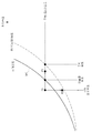
공기의 온도와 습도 사이의 관계는 도 13에 도시된 바와 같은 것으로 알려져 있다. 특정한 습도에서 온도가 감소하면 공기의 수증기가 응결되는 것이 알려져 있으며, 습도가 증가할수록 수증기가 응결하는 온도가 상승하는 것으로 알려져 있다.The relationship between air temperature and humidity is known as shown in FIG. It is known that water vapor condenses when the temperature decreases at a certain humidity, and the temperature at which water vapor condenses increases as the humidity increases.
도 13에 도시된 바와 같이, 다양한 습도에 대하여 수증기가 응결하는 온도를 나타내기 위한 포화 수증기량 곡선(포화 수증기압 곡선) (vapor pressure curve) (VPC)이 도입된다. 도 13의 그래프를 기준으로 공기의 온도와 습도에 의하여 결정되는 지점(P0)이 포화 수증기량 곡선(VPC)보다 상측에 위치하면 수증기가 응결되는 것으로 알려져 있다.As shown in FIG. 13, a saturated steam amount curve (vapor pressure curve) (VPC) is introduced to indicate the temperature at which water vapor condenses for various humidity levels. It is known that water vapor condenses when the point P0 determined by the temperature and humidity of the air is located above the saturated water vapor curve VPC based on the graph of FIG. 13.
공기의 이슬점 온도는 공기의 절대 습도(공기에 포함된 수증기량)에 의존하거나, 공기의 온도와 주변 상대 습도에 의존하는 것으로 알려져 있다.The dew point temperature of air is known to depend on the absolute humidity of the air (the amount of water vapor contained in the air) or on the temperature of the air and the ambient relative humidity.
제어부(190)는 주변 온도와 주변 (상대) 습도로부터 주변 공기의 이슬점 온도를 산출할 수 있다. 구체적으로, 제어부(190)는 [수학식 1]을 이용하여 주변 온도 및 주변 습도로부터 주변 공기의 이슬점 온도를 산출할 수 있다.The
[수학식 1][Equation 1]

단, TDEW는 발광 다이오드 모듈(104)의 주변 공기의 이슬점 온도를 나타내고,Tair는 발광 다이오드 모듈(104)의 주변 공기의 온도를 나타내고, Hair는 발광 다이오드 모듈(104)의 주변 공기의 (상대) 습도를 나타낼 수 있다.However, T DEW represents the dew point temperature of the ambient air of the light emitting
다른 예로, 디스플레이 장치(100)는 외부 장치(,)로부터 주변 온도 및 주변 습도에 관한 정보를 수신하고, 수신된 주변 온도 및 주변 습도로부터 이슬점 온도를 산출할 수 있다.As another example, the
디스플레이 장치(100)의 제어부(190)는 통신부(170)를 통하여 공기조화기(10) 및/또는 제습기(20)로 주변 온도 및 주변 습도에 관한 정보를 요청할 수 있다. 디스플레이 장치(100)의 요청에 응답하여 공기조화기(10) 및/또는 제습기(20)는 주변 온도 및 주변 습도에 관한 정보를 디스플레이 장치(100)로 전송할 수 있다. 제어부(190)는 통신부(170)를 통하여 공기조화기(10) 및/또는 제습기(20)로부터 주변 온도 및 주변 습도를 획득할 수 있다.The
이후, 제어부(190)는 앞서 설명된 [수학식 1]을 이용하여 주변 온도 및 주변 습도로부터 주변 공기의 이슬점 온도를 산출할 수 있다.Thereafter, the
다른 예로, 디스플레이 장치(100)는 외부 장치(,)로부터 이슬점 온도에 관한 정보를 수신할 수 있다.As another example, the
디스플레이 장치(100)의 제어부(190)는 기상 정보를 제공할 수 있는 외부 서버에 디스플레이 장치(100)가 위치한 지역의 이슬점 온도에 관한 정보를 요청할 수 있다. 디스플레이 장치(100)의 요청에 응답하여 외부 서버는 해당 지역의 이슬점 온도에 관한 정보를 디스플레이 장치(100)로 전송할 수 있다. 제어부(190)는 통신부(170)를 통하여 외부 서버로부터 주변 공기의 이슬점 온도를 획득할 수 있다.The
제어부(190)는 환경 감지부(150)를 통하여 측정된 주변 온도 및 주변 습도로부터 이슬점 온도를 산출하고, 환경 감지부(150)가 생략되거나 환경 감지부(150)의 오동작이 감지되면 통신부(170)를 통하여 수신된 주변 온도 및 주변 습도로부터 이슬점 온도를 산출할 수 있다.The
제어부(190)는 통신부(170)를 통하여 수신된 주변 온도 및 주변 습도로부터 이슬점 온도를 산출하고, 통신부(170)를 통하여 외부 장치들(10, 20)과 통신할 수 없으면 환경 감지부(150)를 통하여 측정된 주변 온도 및 주변 습도로부터 이슬점 온도를 산출할 수 있다.The
또한, 제어부(190)는 사용자의 입력에 따라 통신부(170)를 통하여 수신된 주변 온도 및 주변 습도로부터 이슬점 온도를 산출하거나 환경 감지부(150)를 통하여 측정된 주변 온도 및 주변 습도로부터 이슬점 온도를 산출할 수 있다.In addition, the
다른 예로, 디스플레이 장치(100)는 데이터 저장부(180)에 저장된 데이터 베이스로부터 주변 온도 및 주변 습도를 추정하고, 추정된 주변 온도 및 주변 습도에 기초하여 주변 공기의 이슬점 온도를 산출할 수 있다.As another example, the
디스플레이 장치(100)의 제어부(190)는 이슬점 온도에 관한 데이터 베이스를 생성하고, 데이터 저장부(180)에 저장할 수 있다. 제어부(190)는 주변 온도 및 주변 습도와 온도/습도가 측정(획득)된 일시(日時)를 포함하는 데이터 베이스를 생성하고, 데이터 베이스를 데이터 저장부(180)에 저장할 수 있다.The
제어부(190)는 데이터 베이스로부터 현재 일시(日時)의 주변 온도 및 주변 습도를 획득할 수 있다. 제어부(190)는 데이터 베이스로부터 1년전 현재와 동일한 일시(日時)의 주변 온도 및 주변 습도를 현재 일시(日時)의 주변 온도 및 주변 습도로 식별할 수 있다. 또한, 제어부(190)는 현재와 동일한 시각의 최근 10일 동안의 주변 온도 및 주변 습도의 평균값을 현재 일시(日時)의 주변 온도 및 주변 습도로 식별할 수 있다.The
다른 예로, 디스플레이 장치(100)는 데이터 저장부(180)에 저장된 데이터 베이스로부터 이슬점 온도를 추정할 수 있다.As another example, the
디스플레이 장치(100)의 제어부(190)는 이슬점 온도에 관한 데이터 베이스를 생성하고, 데이터 저장부(180)에 저장할 수 있다. 제어부(190)는 이슬점 온도와 이슬점 온도가 산출(획득)된 일시(日時)를 포함하는 데이터 베이스를 생성하고, 데이터 베이스를 데이터 저장부(180)에 저장할 수 있다.The
제어부(190)는 데이터 베이스로부터 현재 일시(日時)의 이슬점 온도를 획득할 수 있다. 제어부(190)는 데이터 베이스로부터 1년전 현재와 동일한 일시(日時)의 이슬점 온도를 현재 일시(日時)의 이슬점 온도로 식별할 수 있다. 또한, 제어부(190)는 현재와 동일한 시각의 최근 10일 동안의 이슬점 온도의 평균값을 현재 일시(日時)의 이슬점 온도로 식별할 수 있다.The
주변 공기의 이슬점 온도를 획득하는 방법은 이상에서 설명된 방법에 한정되지 아니하며, 제어부(190)는 이상에서 기재되지 아니한 다양한 방법으로 주변 공기의 이슬점 온도를 획득할 수 있다.The method of obtaining the dew point temperature of the ambient air is not limited to the method described above, and the
디스플레이 장치(100)는 발광 다이오드 모듈(104)의 온도를 획득한다(1020).The
디스플레이 장치(100)의 제어부(190)는 LED 모듈 온도 센서(155)를 이용하여 발광 다이오드 모듈(104)의 온도를 측정할 수 있다.The
제어부(190)는 발광 다이오드 모듈(104)의 온도를 감지하도록 LED 모듈 온도 센서(155)를 제어할 수 있다. LED 모듈 온도 센서(155)는 발광 다이오드 모듈(104)의 온도에 대응하는 전기적 신호를 제어부(190)로 전달하고, 제어부(190)는 LED 모듈 온도 센서(155)의 전기적 신호로부터 발광 다이오드 모듈(104)의 온도를 식별할 수 있다.The
디스플레이 장치(100)는 발광 다이오드 모듈(104)의 온도가 주변 공기의 이슬점 온도 이하인지를 판단한다(1030).The
제어부(190)는 동작 1020에서 획득된 발광 다이오드 모듈(104)의 온도와 동작 1010에서 획득된 주변 공기의 이슬점 온도를 비교하고, 발광 다이오드 모듈(104)의 온도가 주변 공기의 이슬점 온도 이하인지를 판단할 수 있다.The
발광 다이오드 모듈(104)의 온도가 주변 공기의 이슬점 온도 이하가 아니면(1030의 아니오), 디스플레이 장치(100)는 현재 발광 다이오드 모듈(104)에서 수증기의 응결이 발생하지 않는 것으로 판단할 수 있다.If the temperature of the light emitting
따라서, 디스플레이 장치(100)는 주변 공기의 이슬점 온도 획득과, 발광 다이오드 모듈(104)의 온도 획득과, 발광 다이오드 모듈(104)의 온도와 주변 공기의 이슬점 온도 사이의 비교를 반복할 수 있다.Accordingly, the
발광 다이오드 모듈(104)의 온도가 주변 공기의 이슬점 온도 이하이면(1030의 예), 디스플레이 장치(100)는 수증기의 응결을 방지하기 위한 동작(이하 '응결 방지 동작'이라 한다)을 수행한다(1040).If the temperature of the light emitting
주변 환경에 따라 발광 다이오드 모듈(104)에 수증기가 침투할 수 있다. 예를 들어, 디스플레이 장치(100)가 고온-다습한 환경에 놓인 경우, 디스플레이 장치(100)의 주변 수증기가 발광 다이오드 모듈(104)의 에폭시 수지를 통과하여 발광 다이오드 소자(200)에 도달할 수 있다.Water vapor may penetrate the
발광 다이오드 모듈(104)의 온도가 주변 공기의 이슬점 온도 이하이면 수증기가 발광 다이오드 모듈(104)에 침투한 수증기가 응결될 수 있다. 수증기가 응결된 수분에 의하여 와이어(104a, 104b)의 이온화가 발생할 수 있으며, 발광 다이오드 소자(200)의 단락이 발생할 수 있다. When the temperature of the light emitting
앞서 설명된 바와 같이, 도 13의 그래프를 기준으로 공기의 온도와 습도에 의하여 결정되는 지점(P0)이 포화 수증기량 곡선(VPC)보다 상측에 위치하면 수증기가 응결된다.As described above, if the point P0 determined by the temperature and humidity of the air is located above the saturated water vapor curve VPC based on the graph of FIG. 13, water vapor condenses.
발광 다이오드 모듈(104)의 온도와 주변 공기의 습도에 의하여 결정되는 지점(P0)이 포화 수증기량 곡선(VPC)보다 상측에 위치하면 발광 다이오드 모듈(104)에 침투한 수증기가 응결될 수 있다. 다시 말해, 발광 다이오드 모듈(104)의 온도가 주변 공기의 온도/습도에 의한 이슬점 온도보다 낮으면 발광 다이오드 모듈(104)에 침투한 수증기가 응결될 수 있다.When the point P0 determined by the temperature of the light emitting
디스플레이 장치(100)의 제어부(190)는 다양한 방법으로 수증기가 발광 다이오드 모듈(104)에서 응결되는 것을 방지할 수 있다.The
예를 들어, 디스플레이 장치(100)는 디스플레이 장치(100) 내부의 온도 및/또는 습도를 조절할 수 있다. 제어부(190)는 발광 다이오드 모듈(104)을 가열하거나 발광 다이오드 모듈(104) 주변의 공기를 순환시키도록 온도 조절부(160)를 제어할 수 있다.For example, the
제어부(190)는 발광 다이오드 모듈(104)을 가열하도록 하는 제어 신호를 온도 조절부(160)에 전단할 수 있으며, 온도 조절부(160)는 제어부(190)의 제어 신호에 응답하여 발광 다이오드 모듈(104)을 가열하도록 히터(161)를 제어할 수 있다. 온도 조절부(160)는 히터(161)에 전류를 공급하고, 전류의 공급에 응답하여 히터(161)는 발열할 수 있다.The
히터(161)의 발열에 의하여 발광 다이오드 모듈(104)의 온도가 상승할 수 있으며, 발광 다이오드 모듈(104)의 온도가 이슬점 온도보다 높은 온도까지 상승할 수 있다. 예를 들어, 도 13에 도시된 바와 같이 히터(161)의 발열에 의하여 발광 다이오드 모듈(104)의 온도/습도가 초기 지점(P0)으로부터 제1 지점(P1)으로 이동할 수 있다.The heat of the
그 결과, 발광 다이오드 모듈(104)에 침투한 수증기의 응결이 방지될 수 있다.As a result, condensation of water vapor that has penetrated the light emitting
또한, 제어부(190)는 디스플레이 장치(100) 내부의 공기를 순환시키도록 하는 제어 신호를 온도 조절부(160)에 전단할 수 있으며, 온도 조절부(160)는 제어부(190)의 제어 신호에 응답하여 디스플레이 장치(100) 내부의 공기를 순환시키도록 팬(162)을 제어할 수 있다. 온도 조절부(160)는 팬(162)에 전류를 공급하고, 전류의 공급에 응답하여 팬(162)은 캐비닛(101) 내부의 공기를 순환시킬 수 있다. 팬(162)이 발광 다이오드 모듈(104) 주변의 공기를 순환시킴으로 인하여 발광 다이오드 모듈(104)에 침투한 수증기가 증발되도록 할 수 있다.In addition, the
그 결과, 발광 다이오드 모듈(104)에 침투하는 것이 방지될 수 있으며, 또한 발광 다이오드 모듈(104)에 침투한 수증기가 응결되는 것이 방지될 수 있다.As a result, penetration into the light emitting
다른 예로, 디스플레이 장치(100)는 디스플레이 장치(100)의 주변 온도 및/또는 주변 습도를 조절할 수 있다. 제어부(190)는 공기조화기(10) 및/또는 제습기(20)으로 온도 및/또는 습도를 조절하기 위한 요청을 전송하도록 하는 제어 신호를 온도 조절부(160)로 전달할 수 있다. 온도 조절부(160)는 제어부(190)의 제어 신호에 응답하여 디스플레이 장치(100)의 주변 온도 및/또는 주변 습도를 조절하도록 하는 제어 신호를 통신부(170)를 통하여 공기조화기(10) 및/또는 제습기(20)으로 전송할 수 있다.As another example, the
온도 조절부(160)는 통신부(170)를 통하여 공기조화기(10) 및/또는 제습기(20)에 디스플레이 장치(100)의 주변 공기의 습도를 낮추는 동작(제습 동작)을 요청하는 메시지를 전송할 수 있다.The
공기조화기(10) 및/또는 제습기(20)의 제습 동작에 의하여 주변 공기의 습도가 낮아질 수 있으며, 주변 공기의 습도 하강과 함께 이슬점 온도 역시 함께 하강할 수 있다. 예를 들어, 도 13에 도시된 바와 같이 공기조화기(10) 및/또는 제습기(20)의 제습 동작에 의하여 발광 다이오드 모듈(104)의 온도/습도가 초기 지점(P0)으로부터 제2 지점(P2)으로 이동할 수 있다.The humidity of the ambient air may be lowered by the dehumidifying operation of the
그 결과, 발광 다이오드 모듈(104)에 침투한 수증기의 응결이 방지될 수 있다.As a result, condensation of water vapor that has penetrated the light emitting
또한, 온도 조절부(160)는 통신부(170)를 통하여 공기조화기(10) 및/또는 제습기(20)에 디스플레이 장치(100)의 주변 공기의 온도를 낮추는 동작(냉방 동작)을 요청하는 메시지를 전송할 수 있다. 공기조화기(10) 및/또는 제습기(20)의 냉방 동작에 의하여 주변 공기의 온도가 낮아질 수 있으며, 주변 온도가 이슬점 온도보다 낮아지면 디스플레이 장치(100) 외부에서 수증기가 응결되고 디스플레이 장치(100) 내부의 습도가 낮아질 수 있다.In addition, the
그 결과, 발광 다이오드 모듈(104)에 침투한 수증기의 응결이 방지될 수 있다.As a result, condensation of water vapor that has penetrated the light emitting
이처럼 디스플레이 장치(100)는 다양한 방향으로 수증기가 발광 다이오드 모듈(104)에서 응결되는 것을 방지할 수 있다.As such, the
수증기의 응결을 방지하기 위한 동작 중에, 디스플레이 장치(100)는 주변 공기의 이슬점 온도를 획득한다(1050).During operation to prevent condensation of water vapor, the
동작 1050은 동작 1010과 동일할 수 있다.
수증기의 응결을 방지하기 위한 동작 중에, 디스플레이 장치(100)는 발광 다이오드 모듈(104)의 온도를 획득한다(1060).During operation to prevent condensation of water vapor, the
동작 1060은 동작 1020과 동일할 수 있다.
수증기의 응결을 방지하기 위한 동작 중에, 디스플레이 장치(100)는 발광 다이오드 모듈(104)의 온도가 주변 공기의 이슬점 온도를 초과하는지를 판단한다(1070).During operation to prevent condensation of water vapor, the
제어부(190)는 동작 1060에서 획득된 발광 다이오드 모듈(104)의 온도와 동작 1050에서 획득된 주변 공기의 이슬점 온도를 비교하고, 발광 다이오드 모듈(104)의 온도가 주변 공기의 이슬점 온도 이하인지를 판단할 수 있다.The
발광 다이오드 모듈(104)의 온도가 주변 공기의 이슬점 온도를 초과하지 않으면(1070의 아니오), 디스플레이 장치(100)는 여전히 발광 다이오드 모듈(104)에서 수증기의 응결이 발생하는 것으로 판단할 수 있다.If the temperature of the light emitting
수증기 응결 방지 동작을 계속하는 상태에서, 디스플레이 장치(100)는 주변 공기의 이슬점 온도 획득과, 발광 다이오드 모듈(104)의 온도 획득과, 발광 다이오드 모듈(104)의 온도와 주변 공기의 이슬점 온도 사이의 비교를 반복할 수 있다.In the state of continuing the water vapor condensation preventing operation, the
발광 다이오드 모듈(104)의 온도가 주변 공기의 이슬점 온도를 초과하면(1070의 예), 디스플레이 장치(100)는 응결 방지 동작을 중지한다(1080).When the temperature of the light emitting
발광 다이오드 모듈(104)의 온도가 주변 공기의 이슬점 온도를 초과하면, 디스플레이 장치(100)는 현재 발광 다이오드 모듈(104)에서 수증기의 응결이 발생하지 않는 것으로 판단할 수 있다. 따라서, 디스플레이 장치(100)는 수증기 응결을 방지하기 위한 응결 방지 동작을 중지할 수 있다.When the temperature of the light emitting
이상에서 설명된 바와 같이, 디스플레이 장치(100)는 주변 공기의 이슬점 온도와 발광 다이오드 모듈(104)의 온도에 기초하여 발광 다이오드 모듈(104)의 온도 및/또는 발광 다이오드 모듈(104) 주변의 습도를 조절할 수 있다. 그에 따라서, 발광 다이오드 모듈(104)에 수증기가 침투하는 것이 방지되며, 또한 침투한 수증기가 응결되는 것이 방지될 수 있다.As described above, the
이상의 응결 방지 동작(1000)은 디스플레이 장치(100)에 외부 전원이 연결된 수행될 수 있다. 다시 말해, 이상의 응결 방지 동작(1000)은 디스플레이 장치(100)에 외부 전원이 연결된 동안 계속 수행될 수 있다.The above
사용자로부터 디스플레이 장치(100)의 동작 개시(턴온)을 위한 사용자 입력이 입력되면, 디스플레이 장치(100)는 사용자 입력에 응답하기 위하여 추가적인 동작을 수행할 수 있다.When a user input for starting operation (turn-on) of the
이하에서는 디스플레이 장치(100)의 동작 개시(턴온)을 위한 사용자 입력이 입력된 이후 디스플레이 장치(100)의 수증기 응결 방지 동작이 설명된다.Hereinafter, the operation of preventing water vapor condensation of the
도 14는 일 실시예에 의한 디스플레이 장치가 수증기 응결을 방지하는 동작의 다른 일 예를 도시한다.14 illustrates another example of an operation of preventing display condensation by the display apparatus according to an exemplary embodiment.
도 14와 함께, 디스플레이 장치(100)의 응결 방지 동작(1100)이 설명된다.14, a
응결 방지 동작(1100)은 디스플레이 장치(100)의 동작 개시(턴온)을 위한 사용자 입력 이후 수행될 수 있다. 따라서, 응결 방지 동작(1100)이 수행되는 중에 도 12에 도시된 응결 방지 동작(1000)이 함께 수행될 수 있다.The
응결 방지 동작(1100)은 디스플레이 장치(100)의 동작 개시(턴온)을 위한 사용자 입력에 응답하여 실행되거나, 디스플레이 장치(100)의 동작 개시(턴온)을 위한 사용자 입력이 입력된 이후 미리 정해진 주기마다 자동으로 실행될 수 있다.The
디스플레이 장치(100)는 동작 개시(턴온)을 위한 사용자 입력을 수신한다(1110).The
사용자는 디스플레이 장치(100)의 사용자 입력부(110) 및/또는 리모트 컨트롤러를 통하여 디스플레이 장치(100)에 대한 동작 개시(턴온)를 위한 사용자 입력을 입력할 수 있다. 예를 들어, 사용자는 사용자 입력부(110)의 전원 버튼을 누름으로써 디스플레이 장치(100)에 동작 개시를 위한 사용자 입력을 입력할 수 있다.The user may input a user input for starting operation (turning on) the
동작 개시는 디스플레이 장치(100)가 외부 AC 전원이 연결된 상태에서 디스플레이 장치(100)가 동작을 개시하는 것으로 '소프트 턴온(soft turn-on)'이라고 칭해지기도 하며, '소프트 턴온(soft turn-on)'은 디스플레이 장치(100)에 전원을 연결하는 '하드 턴온(hard turn-on)'과 구별된다.Initiation of the operation is that the
'하드 턴온' 상태에서 제어부(190)는 앞서 설명된 수증기 응결 방지 동작(1000)을 포함한 최소한의 동작을 수행할 수 있다. 예를 들어, 제어부(190)는 대기 모드(standby mode)로 동작하며, 제어부(190)의 일부만이 활성화되거나 낮은 주파수의 클럭에 동기화되어 동작할 수 있다.In the 'hard turn on' state, the
대기 모드에서 디스플레이 장치(100)는 절전 상태(power saving state)일 수 있다. 절전 상태는 외부 AC 전원과의 연결이 끊어진 상태(switch off state) 또는 외부 AC 전원과 연결된 상태(cord connected stat) 또는 신호 수신기(112)를 통하여 리모트 컨트롤러의 신호를 수신하여 전기적으로 처리하는 최소의 회로 부품(미도시)에만 전원이 공급되는 상태 중 적어도 하나일 수 있다.In the standby mode, the
동작 개시를 위한 사용자 입력에 의하여, 디스플레이 장치(100)는 하드 턴온' 상태에서 '소프트 턴온' 상태로 전환될 수 있다. '소프트 턴온' 상태에서 제어부(190)는 디스플레이 장치(100)의 모든 기능을 제공하기 위하여 활성 모드(normal mode)로 전환되며 높은 주파수의 클럭에 동기화되어 동작할 수 있다.By the user input for starting the operation, the
활성 모드에서 디스플레이 장치(100)는 정상 전원 공급 상태(normal power supplying state)일 수 있다. 정상 전원 공급 상태는 사용자의 전원 공급(power on) 명령에 의하여 정상적인 전원이 공급되는 상태일 수 있다.In the active mode, the
동작 개시(턴온)을 위한 사용자 입력이 입력된 이후, 디스플레이 장치(100)는 주변 공기의 이슬점 온도를 획득한다(1120). 디스플레이 장치(100)의 제어부(190)는 환경 감지부(150)에 의하여 측정되거나 공기조화기(10) 및/또는 제습기(20)로부터 수신되거나 데이터 저장부(180)에 저장된 주변 온도 및 주변 습도에 기초하여 이슬점 온도를 산출할 수 있다. 또한, 제어부(190)는 이슬점 온도에 관한 데이터에 기초하여 현재 이슬점 온도를 추정할 수 있다.After the user input for starting operation (turn on) is input, the
동작 1120은 도 12에 도시된 동작 1010과 동일할 수 있다.
디스플레이 장치(100)는 발광 다이오드 모듈(104)의 온도를 획득한다(1130). 디스플레이 장치(100)의 제어부(190)는 LED 모듈 온도 센서(155)를 이용하여 발광 다이오드 모듈(104)의 온도를 측정할 수 있다.The
동작 1130은 도 12에 도시된 동작 1020과 동일할 수 있다.
디스플레이 장치(100)는 발광 다이오드 모듈(104)의 온도가 주변 공기의 이슬점 온도 이하인지를 판단한다(1140). 제어부(190)는 동작 1130에서 획득된 발광 다이오드 모듈(104)의 온도와 동작 1120에서 획득된 주변 공기의 이슬점 온도를 비교하고, 발광 다이오드 모듈(104)의 온도가 주변 공기의 이슬점 온도 이하인지를 판단할 수 있다.The
발광 다이오드 모듈(104)의 온도가 주변 공기의 이슬점 온도 이하가 아니면(1140의 아니오), 디스플레이 장치(100)는 영상을 표시하기 위하여 발광 다이오드 소자(200)를 구동한다(1190).If the temperature of the light emitting
발광 다이오드 모듈(104)의 온도가 주변 공기의 이슬점 온도를 초과이면, 디스플레이 장치(100)는 현재 발광 다이오드 모듈(104)에서 수증기의 응결이 발생하지 않는 것으로 판단할 수 있다. 따라서, 디스플레이 장치(100)는 영상을 표시할 수 있다.If the temperature of the light emitting
발광 다이오드 모듈(104)의 온도가 주변 공기의 이슬점 온도 이하이면(1140의 예), 디스플레이 장치(100)는 적색 발광 다이오드 소자(200r)를 구동한다(1150).If the temperature of the light emitting
발광 다이오드 모듈(104)의 온도가 주변 공기의 이슬점 온도 이하이면 수증기가 발광 다이오드 모듈(104)에 침투한 수증기가 응결될 수 있다..When the temperature of the light emitting
디스플레이 장치(100)의 제어부(190)는 수증기가 발광 다이오드 모듈(104)에 응결되는 것을 방지하기 위하여 적색 발광 다이오드 소자(200r)에 구동 전류를 공급하도록 LED 드라이버(131)를 제어할 수 있다. LED 드라이버(131)는 적색 발광 다이오드 소자(200r)에 구동 전류를 공급할 수 있다.The
구동 전류의 공급에 의하여 적색 발광 다이오드 소자(200r)는 적색 광과 열을 방출할 수 있다. 또한, 적색 발광 다이오드 소자(200r)의 구동에 의하여 발광 다이오드 모듈(104)의 온도가 상승할 수 있으며, 발광 다이오드 모듈(104)의 온도가 이슬점 온도보다 높은 온도까지 상승할 수 있다.The red light emitting
발광 다이오드 모듈(104)를 가열하기 위하여 제어부(190)가 적색 발광 다이오드 소자(200r)에 구동 전류를 공급하는 것에 한정되는 것은 아니며, 제어부(190)는 녹색 발광 다이오드 소자(200g) 및/또는 청색 발광 다이오드 소자(200b)에 구동 전류를 공급할 수 있다.The
적색 발광 다이오드 소자(200r)를 구동하는 중에, 디스플레이 장치(100)는 주변 공기의 이슬점 온도를 획득한다(1160).While driving the red light emitting
동작 1160은 동작 1120과 동일할 수 있다.
적색 발광 다이오드 소자(200r)를 구동하는 중에, 디스플레이 장치(100)는 발광 다이오드 모듈(104)의 온도를 획득한다(1170).While driving the red light emitting
동작 1170은 동작 1130과 동일할 수 있다.
적색 발광 다이오드 소자(200r)를 구동하는 중에, 디스플레이 장치(100)는 발광 다이오드 모듈(104)의 온도가 주변 공기의 이슬점 온도 이상인지를 판단한다(1180).While driving the red light emitting
제어부(190)는 동작 1170에서 획득된 발광 다이오드 모듈(104)의 온도와 동작 1160에서 획득된 주변 공기의 이슬점 온도를 비교하고, 발광 다이오드 모듈(104)의 온도가 주변 공기의 이슬점 온도 이하인지를 판단할 수 있다.The
발광 다이오드 모듈(104)의 온도가 주변 공기의 이슬점 온도 이상이 아니면(1180의 아니오), 디스플레이 장치(100)는 여전히 발광 다이오드 모듈(104)에서 수증기의 응결이 발생하는 것으로 판단할 수 있다.If the temperature of the light emitting
적색 발광 다이오드 소자(200r)를 구동하는 중에, 디스플레이 장치(100)는 주변 공기의 이슬점 온도 획득과, 발광 다이오드 모듈(104)의 온도 획득과, 발광 다이오드 모듈(104)의 온도와 주변 공기의 이슬점 온도 사이의 비교를 반복할 수 있다.While driving the red light emitting
발광 다이오드 모듈(104)의 온도가 주변 공기의 이슬점 온도 이상이면(1180의 예), 디스플레이 장치(100)는 영상을 표시하기 위하여 발광 다이오드 소자(200)를 구동한다(1190).If the temperature of the
발광 다이오드 모듈(104)의 온도가 주변 공기의 이슬점 온도 이상이면, 디스플레이 장치(100)는 현재 발광 다이오드 모듈(104)에서 수증기의 응결이 발생하지 않는 것으로 판단할 수 있다. 특히, 발광 다이오드 모듈(104)의 온도가 주변 공기의 이슬점 온도와 같더라도 발광 다이오드 소자(200)의 구동에 의하여 더욱 가열될 것이 예상되므로 디스플레이 장치(100)는 현재 발광 다이오드 모듈(104)에서 수증기의 응결이 발생하지 않는 것으로 판단할 수 있다.If the temperature of the light emitting
제어부(190)는 컨텐츠 수신부(120)로부터 제공된 영상 데이터를 처리하고, 영상 데이터에 대응하는 영상을 표시하도록 영상 표시부(130)를 제어할 수 있다. 구체적으로, 제어부(190)는 영상 데이터에 따라 적색/녹색/청색 발광 다이오드 소자들(200r, 200g, 200b)에 구동 전류를 공급하도록 LED 드라이버(131)를 제어할 수 있다.The
이상에서 설명된 바와 같이, 디스플레이 장치(100)는 주변 공기의 이슬점 온도와 발광 다이오드 모듈(104)의 온도에 기초하여 적색 발광 다이오드 소자(200r)를 구동할 수 있다. 그에 따라서, 발광 다이오드 모듈(104)이 가열되고, 발광 다이오드 모듈(104)에 침투한 수증기의 응결이 방지될 수 있다.As described above, the
한편, 개시된 실시예들은 컴퓨터에 의해 실행 가능한 명령어를 저장하는 기록매체의 형태로 구현될 수 있다. 명령어는 프로그램 코드의 형태로 저장될 수 있으며, 프로세서에 의해 실행되었을 때, 프로그램 모듈을 생성하여 개시된 실시예들의 동작을 수행할 수 있다. 기록매체는 컴퓨터로 읽을 수 있는 기록매체로 구현될 수 있다.On the other hand, the disclosed embodiments may be implemented in the form of a recording medium for storing instructions executable by a computer. Instructions may be stored in the form of program code, and when executed by a processor, may generate a program module to perform the operations of the disclosed embodiments. The recording medium may be implemented as a computer-readable recording medium.
컴퓨터가 읽을 수 있는 기록매체로는 컴퓨터에 의하여 해독될 수 있는 명령어가 저장된 모든 종류의 기록 매체를 포함한다. 예를 들어, ROM(Read Only Memory), RAM(Random Access Memory), 자기 테이프, 자기 디스크, 플래쉬 메모리, 광 데이터 저장장치 등이 있을 수 있다. Computer-readable recording media include all kinds of recording media having stored thereon instructions which can be read by a computer. For example, there may be a read only memory (ROM), a random access memory (RAM), a magnetic tape, a magnetic disk, a flash memory, an optical data storage device, and the like.
이상에서와 같이 첨부된 도면을 참조하여 개시된 실시예들을 설명하였다. 게시된 실시예가 속하는 기술분야에서 통상의 지식을 가진 자는 게시된 실시예의 기술적 사상이나 필수적인 특징을 변경하지 않고도, 개시된 실시예들과 다른 형태로 실시될 수 있음을 이해할 것이다. 개시된 실시예들은 예시적인 것이며, 한정적으로 해석되어서는 안 된다.As described above, the disclosed embodiments have been described with reference to the accompanying drawings. Those skilled in the art will understand that the disclosed embodiments can be implemented in other forms than the disclosed embodiments without changing the technical spirit or essential features of the disclosed embodiments. The disclosed embodiments are exemplary and should not be construed as limiting.
100: 디스플레이 장치
101: 캐비닛
102: 프레임 브라켓
103: 후면 커버
104: 발광 다이오드 모듈
104a: 와이어
104b: 와이어
104c: 모듈 기판
104d: 에폭시 수지
105: 샤시
106: 제어 어셈블리
107: 전원 어셈블리
108: 전면 커버
110: 사용자 입력부
120: 컨텐츠 수신부
130: 영상 표시부
140: 음향 출력부
150: 환경 감지부
151: 주변 온도 센서
152: 주변 습도 센서
155: LED 모듈 온도 센서
160: 온도 조절부
161: 히터
162: 팬
170: 통신부
180: 데이터 저장부
190: 제어부
200: 발광 다이오드 소자
200r: 적색 발광 다이오드 소자
200g: 녹색 발광 다이오드 소자
200b: 청색 발광 다이오드 소자
210: LED 패키지 기판
220: 사파이어 기판
230: n타입 반도체 층
240: n타입 패드
250: p타입 반도체 층
260: p타입 패드
270: 공핍 층100: display device 101: cabinet
102: frame bracket 103: rear cover
104: light emitting
104b:
104d: epoxy resin 105: chassis
106: control assembly 107: power assembly
108: front cover 110: user input unit
120: content receiving unit 130: video display unit
140: sound output unit 150: environmental sensing unit
151: ambient temperature sensor 152: ambient humidity sensor
155: LED module temperature sensor 160: temperature controller
161: heater 162: fan
170: communication unit 180: data storage unit
190: control unit 200: light emitting diode element
200r: red light emitting
200b: blue light emitting diode element 210: LED package substrate
220: sapphire substrate 230: n-type semiconductor layer
240: n-type pad 250: p-type semiconductor layer
260: p-type pad 270: depletion layer
Claims (20)
상기 캐비닛에 마련된 발광 다이오드 모듈;
외부 장치로부터 상기 캐비닛의 주변 대기 측정값을 수신하는 통신부;
상기 발광 다이오드 모듈에 마련된 온도 센서;
상기 발광 다이오드 모듈의 온도를 조절하는 온도 조절부; 및
절전 상태인 대기 모드에서 상기 온도 센서의 출력에 기초한 측정 온도가 상기 주변 대기 측정값에 기초한 이슬점 온도 이하이면 상기 발광 다이오드 모드의 온도가 상기 이슬점 온도보다 커지도록 상기 온도 조절부를 제어하고,
정상 전원 공급 상태인 활성 모드로 전환 시에 상기 측정 온도가 상기 주변 대기 측정값에 기초한 이슬점 온도 이하이면 상기 발광 다이오드 모드의 온도가 상기 이슬점 온도보다 커지도록 상기 발광 다이오드 모듈을 구동하는 제어부를 포함하는 디스플레이 장치.cabinet;
A light emitting diode module provided in the cabinet;
A communication unit configured to receive an ambient atmospheric measurement value of the cabinet from an external device;
A temperature sensor provided in the light emitting diode module;
A temperature controller controlling a temperature of the light emitting diode module; And
And control the temperature controller so that the temperature of the light emitting diode mode is greater than the dew point temperature when the measured temperature based on the output of the temperature sensor is lower than the dew point temperature based on the ambient atmospheric measurement value in the standby mode in the power saving state.
And a controller configured to drive the light emitting diode module so that the temperature of the light emitting diode mode is greater than the dew point temperature when the measured temperature is lower than the dew point temperature based on the ambient atmospheric measurement value when switching to the active mode in a normal power supply state. Display device.
상기 제어부는 상기 대기 모드 중에 상기 측정 온도가 상기 이슬점 온도보다 작으면 상기 외부 장치가 상기 주변 대기 환경을 조절하도록 하는 제어 신호를 상기 통신부를 통하여 전송하고, 상기 측정 온도가 상기 이슬점 온도보다 커지면 상기 외부 장치의 동작을 중지시키도록 하는 제어 신호를 상기 통신부를 통하여 전송하는 디스플레이 장치.The method of claim 1,
The controller transmits a control signal through the communication unit to allow the external device to adjust the ambient atmospheric environment when the measured temperature is less than the dew point temperature during the standby mode, and when the measured temperature is greater than the dew point temperature. A display device for transmitting a control signal for stopping the operation of the device through the communication unit.
상기 제어부는 상기 활성 모드로 전환 시에 상기 발광 다이오드 모듈에 포함된 적어도 하나의 적색 발광 다이오드 소자를 구동하고, 상기 측정 온도가 상기 이슬점 온도와 같거나 크면 영상을 표시하도록 상기 발광 다이오드 모듈을 제어하는 디스플레이 장치.The method of claim 1,
The control unit controls at least one red light emitting diode element included in the light emitting diode module to switch to the active mode, and controls the light emitting diode module to display an image when the measured temperature is equal to or greater than the dew point temperature. Display device.
상기 발광 다이오드 모듈은 복수의 발광 다이오드 소자와, 상기 복수의 발광 다이오드 소자가 실장된 인쇄 회로 기판을 포함하고, 상기 온도 조절부는 상기 인쇄 회로 기판에 마련된 히터를 포함하고, 상기 대기 모드 중에 상기 측정 온도가 상기 이슬점 온도 이상이면 상기 온도 조절부는 상기 히터를 구동하는 디스플레이 장치.The method of claim 1,
The light emitting diode module includes a plurality of light emitting diode elements and a printed circuit board on which the plurality of light emitting diode elements are mounted, and the temperature controller includes a heater provided on the printed circuit board, and the measured temperature during the standby mode. And the temperature controller is configured to drive the heater when the dew point temperature is equal to or greater than the dew point temperature.
상기 온도 조절부는 상기 캐비닛 내부의 공기를 순환시키는 팬을 포함하여 구성되고,
상기 대기 모드 중에 상기 측정 온도가 상기 이슬점 온도 이상이면 상기 온도 조절부는 상기 팬을 구동하는 디스플레이 장치.The method of claim 1,
The temperature control unit includes a fan circulating air in the cabinet,
And the temperature controller is configured to drive the fan when the measured temperature is greater than the dew point temperature during the standby mode.
상기 주변 대기 환경은 상기 캐비닛의 주변 온도 및 주변 습도를 포함하고,
상기 외부 장치는 상기 캐비닛의 주변 온도 및 주변 습도를 감지하는 센서 모듈을 포함하여 구성되고,
상기 제어부는 상기 통신부를 통하여 상기 센서 모듈의 출력에 기초하여 상기 이슬점 온도를 산출하는 디스플레이 장치.The method of claim 1,
The ambient atmospheric environment comprises an ambient temperature and an ambient humidity of the cabinet,
The external device is configured to include a sensor module for sensing the ambient temperature and ambient humidity of the cabinet,
And the control unit calculates the dew point temperature based on an output of the sensor module through the communication unit.
상기 주변 대기 환경은 상기 캐비닛의 주변 온도 및 주변 습도를 포함하고,
상기 디스플레이 장치는 상기 캐비닛의 주변 온도 및 주변 습도를 감지하는 센서 모듈을 더 포함하고,
상기 제어부는 상기 센서 모듈의 출력에 기초하여 상기 이슬점 온도를 산출하는 디스플레이 장치.The method of claim 1,
The ambient atmospheric environment comprises an ambient temperature and an ambient humidity of the cabinet,
The display device further includes a sensor module for sensing the ambient temperature and ambient humidity of the cabinet,
The control unit calculates the dew point temperature based on the output of the sensor module.
상기 디스플레이 장치는 상기 이슬점 온도와 상기 이슬점 온도가 산출된 일시를 포함하는 데이터를 저장하는 저장부를 더 포함하고,
상기 제어부는 상기 저장부에 저장된 데이터에 기초하여 상기 이슬점을 획득하는 디스플레이 장치.The method of claim 1,
The display apparatus further includes a storage unit for storing data including the dew point temperature and the date and time at which the dew point temperature was calculated,
The control unit obtains the dew point based on the data stored in the storage unit.
이슬점 온도를 산출하고;
절전 상태에서 상기 온도 센서의 출력에 기초한 측정 온도가 상기 디스플레이 장치의 주변 대기 측정값에 기초한 이슬점 온도 이하이면 상기 발광 다이오드 모드의 온도가 상기 이슬점 온도보다 커지도록 상기 온도 조절부를 제어하고;
사용자의 동작 명령에 의하여 상기 절전 상태에서 정상 전원 공급 상태로 전환 시에 상기 측정 온도가 상기 이슬점 온도 이하이면 상기 발광 다이오드 모드의 온도가 상기 이슬점 온도보다 커지도록 상기 발광 다이오드 모듈을 구동하는 것을 포함하는 디스플레이 장치의 제어 방법.A control method of a display apparatus comprising a light emitting diode module, a temperature sensor provided in the light emitting diode module, and a temperature controller configured to adjust a temperature of the light emitting diode module.
Calculate dew point temperature;
Controlling the temperature adjusting unit so that the temperature of the light emitting diode mode is greater than the dew point temperature if the measured temperature based on the output of the temperature sensor is lower than the dew point temperature based on the ambient atmospheric measurement value of the display device in the power saving state;
Driving the light emitting diode module to increase the temperature of the light emitting diode mode to be greater than the dew point temperature when the measured temperature is lower than the dew point temperature when the power saving state is changed to the normal power supply state by a user's operation command. Control method of display device.
상기 절전 상태에서 상기 측정 온도가 상기 이슬점 온도보다 작으면 외부 장치가 상기 주변 대기 환경을 조절하도록 하는 통신부를 통하여 제어 신호를 전송하고;
상기 측정 온도가 상기 이슬점 온도보다 커지면 상기 외부 장치의 동작을 중지시키도록 하는 제어 신호를 상기 통신부를 통하여 전송하는 것을 더 포함하는 디스플레이 장치의 제어 방법.The method of claim 9,
Transmitting a control signal through a communication unit for allowing an external device to adjust the ambient atmospheric environment when the measured temperature is less than the dew point temperature in the power saving state;
And transmitting a control signal through the communication unit to stop the operation of the external device when the measured temperature is greater than the dew point temperature.
상기 정상 전원 공급 상태로 전환 시에 상기 발광 다이오드 모듈에 포함된 적어도 하나의 적색 발광 다이오드 소자를 구동하고;
상기 측정 온도가 상기 이슬점 온도와 같거나 크면 영상을 표시하도록 상기 발광 다이오드 모듈을 제어하는 것을 더 포함하는 디스플레이 장치의 제어 방법.The method of claim 9,
Driving at least one red light emitting diode element included in the light emitting diode module when switching to the normal power supply state;
And controlling the light emitting diode module to display an image when the measured temperature is equal to or greater than the dew point temperature.
상기 절전 상태에서 상기 발광 다이오드 모듈의 온도가 상기 이슬점 온도 이상이면 상기 발광 다이오드 모듈에 포함된 인쇄 회로 기판에 마련된 히터를 구동하는 것을 더 포함하는 디스플레이 장치의 제어 방법.The method of claim 9,
And driving a heater provided in a printed circuit board included in the light emitting diode module when the temperature of the light emitting diode module is greater than the dew point temperature in the power saving state.
상기 절전 상태에서 상기 발광 다이오드 모듈의 온도가 상기 이슬점 온도 이상이면 상기 디스플레이 장치 내부의 공기를 순환시키는 팬을 구동하는 것을 더 포함하는 디스플레이 장치의 제어 방법.The method of claim 9,
And driving a fan circulating air in the display device when the temperature of the light emitting diode module is greater than the dew point temperature in the power saving state.
상기 주변 대기 환경은 상기 디스플레이 장치의 주변 온도 및 주변 습도를 포함하고,
상기 이슬점 온도를 산출하는 것은, 외부 장치로부터 수신된 상기 디스플레이 장치의 주변 온도 및 주변 습도에 기초하여 상기 이슬점 온도를 산출하는 것을 포함하는 디스플레이 장치의 제어 방법.The method of claim 9,
The ambient atmosphere includes an ambient temperature and an ambient humidity of the display device,
The calculating of the dew point temperature includes calculating the dew point temperature based on an ambient temperature and an ambient humidity of the display device received from an external device.
상기 주변 대기 환경은 상기 디스플레이 장치의 주변 온도 및 주변 습도를 포함하고,
상기 이슬점 온도를 산출하는 것은, 상기 디스플레이 장치의 주변 온도 및 주변 습도를 측정하는 센서 모듈의 출력에 기초하여 상기 이슬점 온도를 산출하는 것을 포함하는 디스플레이 장치의 제어 방법.The method of claim 9,
The ambient atmosphere includes an ambient temperature and an ambient humidity of the display device,
The calculating of the dew point temperature includes calculating the dew point temperature based on an output of a sensor module measuring ambient temperature and ambient humidity of the display device.
상기 이슬점 온도와 상기 이슬점 온도가 산출된 일시를 포함하는 데이터를 저장하는 것을 더 포함하고,
상기 이슬점 온도를 산출하는 것은, 상기 저장된 데이터에 기초하여 상기 이슬점을 획득하는 것을 포함하는 디스플레이 장치의 제어 방법.The method of claim 9,
And storing data including the dew point temperature and the date and time at which the dew point temperature was calculated,
Calculating the dew point temperature includes acquiring the dew point based on the stored data.
상기 캐비닛에 마련된 발광 다이오드 모듈;
상기 발광 다이오드 모듈 상에 마련되는 온도 센서;
상기 캐비닛의 주변 공기의 이슬점 온도가 상기 온도 센서의 출력에 기초한 발광 다이오드 모듈의 온도보다 크면 상기 발광 다이오드 모듈에 포함된 적색 발광 다이오드 소자를 선택적으로 구동하는 프로세서는 포함하는 디스플레이 장치.cabinet;
A light emitting diode module provided in the cabinet;
A temperature sensor provided on the light emitting diode module;
And a processor for selectively driving the red light emitting diode element included in the light emitting diode module if the dew point temperature of the ambient air of the cabinet is greater than the temperature of the light emitting diode module based on the output of the temperature sensor.
상기 캐비닛 내부 또는 외부에 마련되는 센서 모듈을 더 포함하고,
상기 프로세서는 상기 센서 모듈의 출력을 기초한 주변 온도 및 주변 습도로부터 이슬점 온도를 산출하는 디스플레이 장치.The method of claim 17,
Further comprising a sensor module provided inside or outside the cabinet,
And the processor calculates the dew point temperature from the ambient temperature and the ambient humidity based on the output of the sensor module.
외부 장치와 데이터를 주고받는 통신부를 더 포함하고,
상기 프로세서는 상기 통신부를 통하여 상기 외부 장치로부터 수신된 주변 온도 및 주변 습도로부터 이슬점 온도를 산출하는 디스플레이 장치.The method of claim 17,
Further comprising a communication unit for exchanging data with an external device,
And the processor calculates a dew point temperature from the ambient temperature and the ambient humidity received from the external device through the communication unit.
상기 이슬점 온도와 상기 이슬점 온도가 산출된 일시를 포함하는 데이터를 저장하는 저장부를 더 포함하고,
상기 프로세서는 상기 저장부에 저장된 데이터에 기초하여 상기 이슬점을 획득하는 디스플레이 장치.The method of claim 17,
The apparatus may further include a storage configured to store data including the dew point temperature and a date and time at which the dew point temperature is calculated.
And the processor is configured to obtain the dew point based on data stored in the storage.
Priority Applications (5)
| Application Number | Priority Date | Filing Date | Title |
|---|---|---|---|
| KR1020180030700A KR20190108965A (en) | 2018-03-16 | 2018-03-16 | Display apparatus and controlling method thereof |
| PCT/KR2019/001132 WO2019177263A1 (en) | 2018-03-16 | 2019-01-25 | Display apparatus and control method thereof |
| CN201980019520.8A CN111868812B (en) | 2018-03-16 | 2019-01-25 | Display apparatus and control method thereof |
| EP19767788.3A EP3748619B1 (en) | 2018-03-16 | 2019-01-25 | Display apparatus and control method thereof |
| US16/981,207 US11049443B2 (en) | 2018-03-16 | 2019-01-25 | Display apparatus and controlling method thereof |
Applications Claiming Priority (1)
| Application Number | Priority Date | Filing Date | Title |
|---|---|---|---|
| KR1020180030700A KR20190108965A (en) | 2018-03-16 | 2018-03-16 | Display apparatus and controlling method thereof |
Publications (1)
| Publication Number | Publication Date |
|---|---|
| KR20190108965A true KR20190108965A (en) | 2019-09-25 |
Family
ID=67907930
Family Applications (1)
| Application Number | Title | Priority Date | Filing Date |
|---|---|---|---|
| KR1020180030700A KR20190108965A (en) | 2018-03-16 | 2018-03-16 | Display apparatus and controlling method thereof |
Country Status (5)
| Country | Link |
|---|---|
| US (1) | US11049443B2 (en) |
| EP (1) | EP3748619B1 (en) |
| KR (1) | KR20190108965A (en) |
| CN (1) | CN111868812B (en) |
| WO (1) | WO2019177263A1 (en) |
Cited By (3)
| Publication number | Priority date | Publication date | Assignee | Title |
|---|---|---|---|---|
| KR20210145697A (en) * | 2021-11-15 | 2021-12-02 | 주식회사콘스탄텍 | The display system for livestock market acution information |
| US11432383B2 (en) | 2020-12-15 | 2022-08-30 | Samsung Electronics Co., Ltd. | Modular display apparatus and method for controlling thereof |
| WO2023243901A1 (en) * | 2022-06-14 | 2023-12-21 | 삼성전자주식회사 | Display device and control method thereof |
Families Citing this family (7)
| Publication number | Priority date | Publication date | Assignee | Title |
|---|---|---|---|---|
| KR102379106B1 (en) | 2016-10-06 | 2022-03-25 | 아이맥스 시어터스 인터내셔널 리미티드 | Cinema Luminous Screen and Sound System |
| EP3642825A1 (en) | 2017-06-20 | 2020-04-29 | IMAX Theatres International Limited | Active display with reduced screen-door effect |
| WO2019058307A1 (en) * | 2017-09-20 | 2019-03-28 | Imax Theatres International Limited | Light emitting display with tiles and data processing |
| DE102019106527A1 (en) * | 2019-03-14 | 2020-09-17 | OSRAM Opto Semiconductors Gesellschaft mit beschränkter Haftung | METHOD OF OPERATING AN OPTICAL DISPLAY DEVICE AND OPTICAL DISPLAY DEVICE |
| USD954147S1 (en) * | 2019-12-09 | 2022-06-07 | Roe Visual Co., Ltd. | LED display screen |
| CN111031361B (en) * | 2019-12-25 | 2021-11-16 | 河北润森信息科技有限公司 | Open-air cinema system |
| USD954149S1 (en) * | 2020-05-20 | 2022-06-07 | H2Vr Holdco, Inc. | LED tile |
Family Cites Families (28)
| Publication number | Priority date | Publication date | Assignee | Title |
|---|---|---|---|---|
| US4035644A (en) * | 1975-07-01 | 1977-07-12 | Ciemochowski Michael F | Atmospheric condition detecting and indicating apparatus and method |
| US20050134525A1 (en) * | 2003-12-23 | 2005-06-23 | Gino Tanghe | Control system for a tiled large-screen emissive display |
| KR20070042421A (en) * | 2005-10-18 | 2007-04-23 | 삼성에스디아이 주식회사 | Flat panel display having a thermostat |
| JP4766499B2 (en) * | 2009-01-19 | 2011-09-07 | 三洋電機株式会社 | Outdoor image display device |
| JP2011150034A (en) * | 2010-01-20 | 2011-08-04 | Tecnart:Kk | Liquid crystal display |
| CN102791121A (en) * | 2010-04-09 | 2012-11-21 | 夏普株式会社 | Lighting device, plant cultivation device, and method for cooling lighting device |
| KR101737391B1 (en) * | 2011-02-01 | 2017-05-30 | 삼성전자주식회사 | Outdoor display apparatus |
| JP5721814B2 (en) * | 2011-04-11 | 2015-05-20 | 株式会社アシスト | Display device |
| US9808375B2 (en) * | 2012-02-16 | 2017-11-07 | Abominable Labs, Llc | Power-saving method for defogging an eye-shield |
| JP6120496B2 (en) * | 2012-06-15 | 2017-04-26 | 三菱電機株式会社 | Light source device |
| JP5983431B2 (en) * | 2013-01-28 | 2016-08-31 | ブラザー工業株式会社 | Image forming apparatus |
| JP2014153446A (en) * | 2013-02-06 | 2014-08-25 | Panasonic Corp | Display device |
| KR101336970B1 (en) * | 2013-04-18 | 2013-12-04 | 주식회사 엣지아이앤디 | The device of preventing fog for display apparatus |
| US9152178B2 (en) * | 2013-11-06 | 2015-10-06 | Symbol Technologies, Llc | Environmental controls for mobile electronic devices |
| KR101550106B1 (en) * | 2013-12-11 | 2015-09-04 | 인하대학교 산학협력단 | LED lighting system |
| KR101974200B1 (en) * | 2014-04-14 | 2019-04-30 | 삼성전자주식회사 | Multi display system, electronic apparatus and method for outputting a content |
| KR20160056197A (en) * | 2014-11-11 | 2016-05-19 | 삼성전자주식회사 | Method for controlling display and electronic device thereof |
| CN104317339A (en) * | 2014-11-13 | 2015-01-28 | 国家电网公司 | Dehumidification and anti-condensation intelligent control system and method for ring main unit |
| KR102456724B1 (en) * | 2015-09-30 | 2022-10-21 | 엘지디스플레이 주식회사 | Timing controller, display panel, organic light emitting display device, and the method for driving the organic light emitting display device |
| US10175926B1 (en) * | 2016-05-02 | 2019-01-08 | Mehuva, Inc. | Multifunction proximity digital billboard |
| US10827657B2 (en) * | 2016-08-10 | 2020-11-03 | Keyser Industries Inc. | Display system with canopy |
| US10244669B2 (en) * | 2016-08-10 | 2019-03-26 | Keyser Industries, Inc. | Display system |
| DE102017217881A1 (en) * | 2016-11-08 | 2018-05-09 | Heidelberger Druckmaschinen Ag | Method for operating a UV curing device of a printing press |
| CN106898294A (en) * | 2017-03-28 | 2017-06-27 | 广州兴图计算机有限公司 | A kind of LED display screen system based on DSP |
| GB2561895B (en) * | 2017-04-28 | 2019-10-16 | Amscreen Group Ltd | Cooling of electronic displays |
| US11694601B2 (en) * | 2019-03-29 | 2023-07-04 | Creeled, Inc. | Active control of light emitting diodes and light emitting diode displays |
| KR20210019900A (en) * | 2019-08-13 | 2021-02-23 | 삼성전자주식회사 | Display apparatus and control method thereof |
| KR20210020537A (en) * | 2019-08-16 | 2021-02-24 | 삼성전자주식회사 | Display apparatus and controlling method thereof |
-
2018
- 2018-03-16 KR KR1020180030700A patent/KR20190108965A/en not_active Application Discontinuation
-
2019
- 2019-01-25 US US16/981,207 patent/US11049443B2/en active Active
- 2019-01-25 EP EP19767788.3A patent/EP3748619B1/en active Active
- 2019-01-25 CN CN201980019520.8A patent/CN111868812B/en active Active
- 2019-01-25 WO PCT/KR2019/001132 patent/WO2019177263A1/en unknown
Cited By (3)
| Publication number | Priority date | Publication date | Assignee | Title |
|---|---|---|---|---|
| US11432383B2 (en) | 2020-12-15 | 2022-08-30 | Samsung Electronics Co., Ltd. | Modular display apparatus and method for controlling thereof |
| KR20210145697A (en) * | 2021-11-15 | 2021-12-02 | 주식회사콘스탄텍 | The display system for livestock market acution information |
| WO2023243901A1 (en) * | 2022-06-14 | 2023-12-21 | 삼성전자주식회사 | Display device and control method thereof |
Also Published As
| Publication number | Publication date |
|---|---|
| EP3748619A1 (en) | 2020-12-09 |
| EP3748619A4 (en) | 2021-03-10 |
| US20210134212A1 (en) | 2021-05-06 |
| US11049443B2 (en) | 2021-06-29 |
| EP3748619B1 (en) | 2023-12-20 |
| CN111868812A (en) | 2020-10-30 |
| WO2019177263A1 (en) | 2019-09-19 |
| CN111868812B (en) | 2024-03-29 |
Similar Documents
| Publication | Publication Date | Title |
|---|---|---|
| EP3748619B1 (en) | Display apparatus and control method thereof | |
| US20230055281A1 (en) | Display apparatus and control method thereof | |
| JP5481626B1 (en) | Illumination device and liquid crystal display device | |
| US11269584B2 (en) | Display system, control method of the display system, and display apparatus | |
| KR102393370B1 (en) | Organic light emitting display apparatus and driving method thereof | |
| KR20190079921A (en) | Image processing apparatus, mage processing method and multi-screen display | |
| CN109036291B (en) | Display panel, control method thereof and display device | |
| CN114930445A (en) | Display device and light emitting device thereof | |
| US10706763B2 (en) | Organic light emitting diode display device for moving image and method for operating thereof | |
| KR20060132222A (en) | Organic light emitting display device and driving method thereof | |
| US20210116958A1 (en) | Display device | |
| US11024222B2 (en) | Display device and control method thereof | |
| KR102305357B1 (en) | A system for adjusting the color temperature of a transparent display device and a method for adjusting the color temperature of a transparent display device | |
| US11195478B2 (en) | Display apparatus and method of controlling the same | |
| CN114648963B (en) | Display device and light emitting apparatus | |
| US20210088848A1 (en) | Display apparatus and control method thereof | |
| US20240127745A1 (en) | Display device and method for controlling same | |
| US20230042596A1 (en) | Image display device and operation method thereof | |
| US20230389160A1 (en) | Display apparatus and method of controlling the same | |
| KR20220122190A (en) | Display apparatus and light apparatus thereof | |
| KR102416838B1 (en) | Display apparatus and control method of the same | |
| KR100670174B1 (en) | Light emitting display | |
| KR20210029549A (en) | Display apparatus and controlling method thereof | |
| KR20230163861A (en) | Display apparatus and control method for the same |
Legal Events
| Date | Code | Title | Description |
|---|---|---|---|
| E601 | Decision to refuse application | ||
| E601 | Decision to refuse application | ||
| E801 | Decision on dismissal of amendment |