KR20190101502A - Display with observer tracking - Google Patents
Display with observer tracking Download PDFInfo
- Publication number
- KR20190101502A KR20190101502A KR1020197024666A KR20197024666A KR20190101502A KR 20190101502 A KR20190101502 A KR 20190101502A KR 1020197024666 A KR1020197024666 A KR 1020197024666A KR 20197024666 A KR20197024666 A KR 20197024666A KR 20190101502 A KR20190101502 A KR 20190101502A
- Authority
- KR
- South Korea
- Prior art keywords
- grid
- polarization
- light
- controllable
- deflection
- Prior art date
Links
- 230000010287 polarization Effects 0.000 claims abstract description 197
- 238000005286 illumination Methods 0.000 claims description 39
- 230000003287 optical effect Effects 0.000 claims description 20
- 239000011159 matrix material Substances 0.000 claims description 11
- 239000006185 dispersion Substances 0.000 claims description 3
- 230000000694 effects Effects 0.000 claims description 3
- 238000000034 method Methods 0.000 claims 24
- 230000004913 activation Effects 0.000 abstract 1
- 239000004973 liquid crystal related substance Substances 0.000 description 20
- 210000004027 cell Anatomy 0.000 description 4
- 210000002858 crystal cell Anatomy 0.000 description 3
- 238000001228 spectrum Methods 0.000 description 3
- 230000001360 synchronised effect Effects 0.000 description 3
- 238000003491 array Methods 0.000 description 2
- 230000001427 coherent effect Effects 0.000 description 2
- 239000003086 colorant Substances 0.000 description 2
- 238000009826 distribution Methods 0.000 description 2
- 238000003384 imaging method Methods 0.000 description 2
- 230000000737 periodic effect Effects 0.000 description 2
- 239000004988 Nematic liquid crystal Substances 0.000 description 1
- 230000015572 biosynthetic process Effects 0.000 description 1
- 239000000470 constituent Substances 0.000 description 1
- 230000001419 dependent effect Effects 0.000 description 1
- 230000004424 eye movement Effects 0.000 description 1
- 210000000887 face Anatomy 0.000 description 1
- 239000011521 glass Substances 0.000 description 1
- 238000009434 installation Methods 0.000 description 1
- 230000011218 segmentation Effects 0.000 description 1
- 230000003595 spectral effect Effects 0.000 description 1
- 239000000758 substrate Substances 0.000 description 1
Images


Classifications
-
- G—PHYSICS
- G02—OPTICS
- G02B—OPTICAL ELEMENTS, SYSTEMS OR APPARATUS
- G02B27/00—Optical systems or apparatus not provided for by any of the groups G02B1/00 - G02B26/00, G02B30/00
- G02B27/0093—Optical systems or apparatus not provided for by any of the groups G02B1/00 - G02B26/00, G02B30/00 with means for monitoring data relating to the user, e.g. head-tracking, eye-tracking
-
- G—PHYSICS
- G02—OPTICS
- G02B—OPTICAL ELEMENTS, SYSTEMS OR APPARATUS
- G02B26/00—Optical devices or arrangements for the control of light using movable or deformable optical elements
- G02B26/08—Optical devices or arrangements for the control of light using movable or deformable optical elements for controlling the direction of light
- G02B26/0808—Optical devices or arrangements for the control of light using movable or deformable optical elements for controlling the direction of light by means of one or more diffracting elements
-
- G—PHYSICS
- G02—OPTICS
- G02B—OPTICAL ELEMENTS, SYSTEMS OR APPARATUS
- G02B27/00—Optical systems or apparatus not provided for by any of the groups G02B1/00 - G02B26/00, G02B30/00
- G02B27/28—Optical systems or apparatus not provided for by any of the groups G02B1/00 - G02B26/00, G02B30/00 for polarising
- G02B27/286—Optical systems or apparatus not provided for by any of the groups G02B1/00 - G02B26/00, G02B30/00 for polarising for controlling or changing the state of polarisation, e.g. transforming one polarisation state into another
-
- G—PHYSICS
- G02—OPTICS
- G02B—OPTICAL ELEMENTS, SYSTEMS OR APPARATUS
- G02B27/00—Optical systems or apparatus not provided for by any of the groups G02B1/00 - G02B26/00, G02B30/00
- G02B27/42—Diffraction optics, i.e. systems including a diffractive element being designed for providing a diffractive effect
- G02B27/4272—Diffraction optics, i.e. systems including a diffractive element being designed for providing a diffractive effect having plural diffractive elements positioned sequentially along the optical path
-
- G—PHYSICS
- G02—OPTICS
- G02B—OPTICAL ELEMENTS, SYSTEMS OR APPARATUS
- G02B30/00—Optical systems or apparatus for producing three-dimensional [3D] effects, e.g. stereoscopic images
- G02B30/20—Optical systems or apparatus for producing three-dimensional [3D] effects, e.g. stereoscopic images by providing first and second parallax images to an observer's left and right eyes
- G02B30/22—Optical systems or apparatus for producing three-dimensional [3D] effects, e.g. stereoscopic images by providing first and second parallax images to an observer's left and right eyes of the stereoscopic type
- G02B30/25—Optical systems or apparatus for producing three-dimensional [3D] effects, e.g. stereoscopic images by providing first and second parallax images to an observer's left and right eyes of the stereoscopic type using polarisation techniques
-
- G—PHYSICS
- G02—OPTICS
- G02B—OPTICAL ELEMENTS, SYSTEMS OR APPARATUS
- G02B30/00—Optical systems or apparatus for producing three-dimensional [3D] effects, e.g. stereoscopic images
- G02B30/20—Optical systems or apparatus for producing three-dimensional [3D] effects, e.g. stereoscopic images by providing first and second parallax images to an observer's left and right eyes
- G02B30/26—Optical systems or apparatus for producing three-dimensional [3D] effects, e.g. stereoscopic images by providing first and second parallax images to an observer's left and right eyes of the autostereoscopic type
- G02B30/30—Optical systems or apparatus for producing three-dimensional [3D] effects, e.g. stereoscopic images by providing first and second parallax images to an observer's left and right eyes of the autostereoscopic type involving parallax barriers
- G02B30/31—Optical systems or apparatus for producing three-dimensional [3D] effects, e.g. stereoscopic images by providing first and second parallax images to an observer's left and right eyes of the autostereoscopic type involving parallax barriers involving active parallax barriers
-
- G—PHYSICS
- G02—OPTICS
- G02B—OPTICAL ELEMENTS, SYSTEMS OR APPARATUS
- G02B5/00—Optical elements other than lenses
- G02B5/20—Filters
- G02B5/201—Filters in the form of arrays
-
- G—PHYSICS
- G02—OPTICS
- G02B—OPTICAL ELEMENTS, SYSTEMS OR APPARATUS
- G02B5/00—Optical elements other than lenses
- G02B5/32—Holograms used as optical elements
-
- G—PHYSICS
- G02—OPTICS
- G02F—OPTICAL DEVICES OR ARRANGEMENTS FOR THE CONTROL OF LIGHT BY MODIFICATION OF THE OPTICAL PROPERTIES OF THE MEDIA OF THE ELEMENTS INVOLVED THEREIN; NON-LINEAR OPTICS; FREQUENCY-CHANGING OF LIGHT; OPTICAL LOGIC ELEMENTS; OPTICAL ANALOGUE/DIGITAL CONVERTERS
- G02F1/00—Devices or arrangements for the control of the intensity, colour, phase, polarisation or direction of light arriving from an independent light source, e.g. switching, gating or modulating; Non-linear optics
- G02F1/01—Devices or arrangements for the control of the intensity, colour, phase, polarisation or direction of light arriving from an independent light source, e.g. switching, gating or modulating; Non-linear optics for the control of the intensity, phase, polarisation or colour
- G02F1/0136—Devices or arrangements for the control of the intensity, colour, phase, polarisation or direction of light arriving from an independent light source, e.g. switching, gating or modulating; Non-linear optics for the control of the intensity, phase, polarisation or colour for the control of polarisation, e.g. state of polarisation [SOP] control, polarisation scrambling, TE-TM mode conversion or separation
-
- G—PHYSICS
- G02—OPTICS
- G02F—OPTICAL DEVICES OR ARRANGEMENTS FOR THE CONTROL OF LIGHT BY MODIFICATION OF THE OPTICAL PROPERTIES OF THE MEDIA OF THE ELEMENTS INVOLVED THEREIN; NON-LINEAR OPTICS; FREQUENCY-CHANGING OF LIGHT; OPTICAL LOGIC ELEMENTS; OPTICAL ANALOGUE/DIGITAL CONVERTERS
- G02F1/00—Devices or arrangements for the control of the intensity, colour, phase, polarisation or direction of light arriving from an independent light source, e.g. switching, gating or modulating; Non-linear optics
- G02F1/01—Devices or arrangements for the control of the intensity, colour, phase, polarisation or direction of light arriving from an independent light source, e.g. switching, gating or modulating; Non-linear optics for the control of the intensity, phase, polarisation or colour
- G02F1/13—Devices or arrangements for the control of the intensity, colour, phase, polarisation or direction of light arriving from an independent light source, e.g. switching, gating or modulating; Non-linear optics for the control of the intensity, phase, polarisation or colour based on liquid crystals, e.g. single liquid crystal display cells
- G02F1/1323—Arrangements for providing a switchable viewing angle
-
- G—PHYSICS
- G02—OPTICS
- G02F—OPTICAL DEVICES OR ARRANGEMENTS FOR THE CONTROL OF LIGHT BY MODIFICATION OF THE OPTICAL PROPERTIES OF THE MEDIA OF THE ELEMENTS INVOLVED THEREIN; NON-LINEAR OPTICS; FREQUENCY-CHANGING OF LIGHT; OPTICAL LOGIC ELEMENTS; OPTICAL ANALOGUE/DIGITAL CONVERTERS
- G02F1/00—Devices or arrangements for the control of the intensity, colour, phase, polarisation or direction of light arriving from an independent light source, e.g. switching, gating or modulating; Non-linear optics
- G02F1/01—Devices or arrangements for the control of the intensity, colour, phase, polarisation or direction of light arriving from an independent light source, e.g. switching, gating or modulating; Non-linear optics for the control of the intensity, phase, polarisation or colour
- G02F1/13—Devices or arrangements for the control of the intensity, colour, phase, polarisation or direction of light arriving from an independent light source, e.g. switching, gating or modulating; Non-linear optics for the control of the intensity, phase, polarisation or colour based on liquid crystals, e.g. single liquid crystal display cells
- G02F1/133—Constructional arrangements; Operation of liquid crystal cells; Circuit arrangements
- G02F1/1333—Constructional arrangements; Manufacturing methods
- G02F1/1337—Surface-induced orientation of the liquid crystal molecules, e.g. by alignment layers
- G02F1/133753—Surface-induced orientation of the liquid crystal molecules, e.g. by alignment layers with different alignment orientations or pretilt angles on a same surface, e.g. for grey scale or improved viewing angle
-
- G—PHYSICS
- G02—OPTICS
- G02F—OPTICAL DEVICES OR ARRANGEMENTS FOR THE CONTROL OF LIGHT BY MODIFICATION OF THE OPTICAL PROPERTIES OF THE MEDIA OF THE ELEMENTS INVOLVED THEREIN; NON-LINEAR OPTICS; FREQUENCY-CHANGING OF LIGHT; OPTICAL LOGIC ELEMENTS; OPTICAL ANALOGUE/DIGITAL CONVERTERS
- G02F1/00—Devices or arrangements for the control of the intensity, colour, phase, polarisation or direction of light arriving from an independent light source, e.g. switching, gating or modulating; Non-linear optics
- G02F1/29—Devices or arrangements for the control of the intensity, colour, phase, polarisation or direction of light arriving from an independent light source, e.g. switching, gating or modulating; Non-linear optics for the control of the position or the direction of light beams, i.e. deflection
- G02F1/292—Devices or arrangements for the control of the intensity, colour, phase, polarisation or direction of light arriving from an independent light source, e.g. switching, gating or modulating; Non-linear optics for the control of the position or the direction of light beams, i.e. deflection by controlled diffraction or phased-array beam steering
-
- G—PHYSICS
- G03—PHOTOGRAPHY; CINEMATOGRAPHY; ANALOGOUS TECHNIQUES USING WAVES OTHER THAN OPTICAL WAVES; ELECTROGRAPHY; HOLOGRAPHY
- G03H—HOLOGRAPHIC PROCESSES OR APPARATUS
- G03H1/00—Holographic processes or apparatus using light, infrared or ultraviolet waves for obtaining holograms or for obtaining an image from them; Details peculiar thereto
- G03H1/04—Processes or apparatus for producing holograms
- G03H1/10—Processes or apparatus for producing holograms using modulated reference beam
- G03H1/12—Spatial modulation, e.g. ghost imaging
-
- G—PHYSICS
- G03—PHOTOGRAPHY; CINEMATOGRAPHY; ANALOGOUS TECHNIQUES USING WAVES OTHER THAN OPTICAL WAVES; ELECTROGRAPHY; HOLOGRAPHY
- G03H—HOLOGRAPHIC PROCESSES OR APPARATUS
- G03H1/00—Holographic processes or apparatus using light, infrared or ultraviolet waves for obtaining holograms or for obtaining an image from them; Details peculiar thereto
- G03H1/22—Processes or apparatus for obtaining an optical image from holograms
- G03H1/2286—Particular reconstruction light ; Beam properties
-
- G—PHYSICS
- G03—PHOTOGRAPHY; CINEMATOGRAPHY; ANALOGOUS TECHNIQUES USING WAVES OTHER THAN OPTICAL WAVES; ELECTROGRAPHY; HOLOGRAPHY
- G03H—HOLOGRAPHIC PROCESSES OR APPARATUS
- G03H1/00—Holographic processes or apparatus using light, infrared or ultraviolet waves for obtaining holograms or for obtaining an image from them; Details peculiar thereto
- G03H1/22—Processes or apparatus for obtaining an optical image from holograms
- G03H1/2294—Addressing the hologram to an active spatial light modulator
-
- G—PHYSICS
- G06—COMPUTING; CALCULATING OR COUNTING
- G06F—ELECTRIC DIGITAL DATA PROCESSING
- G06F3/00—Input arrangements for transferring data to be processed into a form capable of being handled by the computer; Output arrangements for transferring data from processing unit to output unit, e.g. interface arrangements
- G06F3/01—Input arrangements or combined input and output arrangements for interaction between user and computer
- G06F3/011—Arrangements for interaction with the human body, e.g. for user immersion in virtual reality
- G06F3/013—Eye tracking input arrangements
-
- H—ELECTRICITY
- H04—ELECTRIC COMMUNICATION TECHNIQUE
- H04N—PICTORIAL COMMUNICATION, e.g. TELEVISION
- H04N13/00—Stereoscopic video systems; Multi-view video systems; Details thereof
- H04N13/30—Image reproducers
- H04N13/302—Image reproducers for viewing without the aid of special glasses, i.e. using autostereoscopic displays
- H04N13/31—Image reproducers for viewing without the aid of special glasses, i.e. using autostereoscopic displays using parallax barriers
- H04N13/315—Image reproducers for viewing without the aid of special glasses, i.e. using autostereoscopic displays using parallax barriers the parallax barriers being time-variant
-
- H—ELECTRICITY
- H04—ELECTRIC COMMUNICATION TECHNIQUE
- H04N—PICTORIAL COMMUNICATION, e.g. TELEVISION
- H04N13/00—Stereoscopic video systems; Multi-view video systems; Details thereof
- H04N13/30—Image reproducers
- H04N13/302—Image reproducers for viewing without the aid of special glasses, i.e. using autostereoscopic displays
- H04N13/32—Image reproducers for viewing without the aid of special glasses, i.e. using autostereoscopic displays using arrays of controllable light sources; using moving apertures or moving light sources
-
- H—ELECTRICITY
- H04—ELECTRIC COMMUNICATION TECHNIQUE
- H04N—PICTORIAL COMMUNICATION, e.g. TELEVISION
- H04N13/00—Stereoscopic video systems; Multi-view video systems; Details thereof
- H04N13/30—Image reproducers
- H04N13/366—Image reproducers using viewer tracking
-
- H—ELECTRICITY
- H04—ELECTRIC COMMUNICATION TECHNIQUE
- H04N—PICTORIAL COMMUNICATION, e.g. TELEVISION
- H04N13/00—Stereoscopic video systems; Multi-view video systems; Details thereof
- H04N13/30—Image reproducers
- H04N13/366—Image reproducers using viewer tracking
- H04N13/368—Image reproducers using viewer tracking for two or more viewers
-
- H—ELECTRICITY
- H04—ELECTRIC COMMUNICATION TECHNIQUE
- H04N—PICTORIAL COMMUNICATION, e.g. TELEVISION
- H04N13/00—Stereoscopic video systems; Multi-view video systems; Details thereof
- H04N13/30—Image reproducers
- H04N13/366—Image reproducers using viewer tracking
- H04N13/383—Image reproducers using viewer tracking for tracking with gaze detection, i.e. detecting the lines of sight of the viewer's eyes
-
- H—ELECTRICITY
- H04—ELECTRIC COMMUNICATION TECHNIQUE
- H04N—PICTORIAL COMMUNICATION, e.g. TELEVISION
- H04N13/00—Stereoscopic video systems; Multi-view video systems; Details thereof
- H04N13/30—Image reproducers
- H04N13/388—Volumetric displays, i.e. systems where the image is built up from picture elements distributed through a volume
- H04N13/39—Volumetric displays, i.e. systems where the image is built up from picture elements distributed through a volume the picture elements emitting light at places where a pair of light beams intersect in a transparent material
-
- H—ELECTRICITY
- H04—ELECTRIC COMMUNICATION TECHNIQUE
- H04N—PICTORIAL COMMUNICATION, e.g. TELEVISION
- H04N13/00—Stereoscopic video systems; Multi-view video systems; Details thereof
- H04N13/30—Image reproducers
- H04N13/398—Synchronisation thereof; Control thereof
-
- G—PHYSICS
- G02—OPTICS
- G02F—OPTICAL DEVICES OR ARRANGEMENTS FOR THE CONTROL OF LIGHT BY MODIFICATION OF THE OPTICAL PROPERTIES OF THE MEDIA OF THE ELEMENTS INVOLVED THEREIN; NON-LINEAR OPTICS; FREQUENCY-CHANGING OF LIGHT; OPTICAL LOGIC ELEMENTS; OPTICAL ANALOGUE/DIGITAL CONVERTERS
- G02F1/00—Devices or arrangements for the control of the intensity, colour, phase, polarisation or direction of light arriving from an independent light source, e.g. switching, gating or modulating; Non-linear optics
- G02F1/01—Devices or arrangements for the control of the intensity, colour, phase, polarisation or direction of light arriving from an independent light source, e.g. switching, gating or modulating; Non-linear optics for the control of the intensity, phase, polarisation or colour
- G02F1/13—Devices or arrangements for the control of the intensity, colour, phase, polarisation or direction of light arriving from an independent light source, e.g. switching, gating or modulating; Non-linear optics for the control of the intensity, phase, polarisation or colour based on liquid crystals, e.g. single liquid crystal display cells
- G02F1/133—Constructional arrangements; Operation of liquid crystal cells; Circuit arrangements
- G02F1/1333—Constructional arrangements; Manufacturing methods
- G02F1/1335—Structural association of cells with optical devices, e.g. polarisers or reflectors
- G02F1/13363—Birefringent elements, e.g. for optical compensation
- G02F1/133631—Birefringent elements, e.g. for optical compensation with a spatial distribution of the retardation value
-
- G—PHYSICS
- G02—OPTICS
- G02F—OPTICAL DEVICES OR ARRANGEMENTS FOR THE CONTROL OF LIGHT BY MODIFICATION OF THE OPTICAL PROPERTIES OF THE MEDIA OF THE ELEMENTS INVOLVED THEREIN; NON-LINEAR OPTICS; FREQUENCY-CHANGING OF LIGHT; OPTICAL LOGIC ELEMENTS; OPTICAL ANALOGUE/DIGITAL CONVERTERS
- G02F1/00—Devices or arrangements for the control of the intensity, colour, phase, polarisation or direction of light arriving from an independent light source, e.g. switching, gating or modulating; Non-linear optics
- G02F1/01—Devices or arrangements for the control of the intensity, colour, phase, polarisation or direction of light arriving from an independent light source, e.g. switching, gating or modulating; Non-linear optics for the control of the intensity, phase, polarisation or colour
- G02F1/13—Devices or arrangements for the control of the intensity, colour, phase, polarisation or direction of light arriving from an independent light source, e.g. switching, gating or modulating; Non-linear optics for the control of the intensity, phase, polarisation or colour based on liquid crystals, e.g. single liquid crystal display cells
- G02F1/133—Constructional arrangements; Operation of liquid crystal cells; Circuit arrangements
- G02F1/1333—Constructional arrangements; Manufacturing methods
- G02F1/1335—Structural association of cells with optical devices, e.g. polarisers or reflectors
- G02F1/13363—Birefringent elements, e.g. for optical compensation
- G02F1/133638—Waveplates, i.e. plates with a retardation value of lambda/n
-
- G—PHYSICS
- G02—OPTICS
- G02F—OPTICAL DEVICES OR ARRANGEMENTS FOR THE CONTROL OF LIGHT BY MODIFICATION OF THE OPTICAL PROPERTIES OF THE MEDIA OF THE ELEMENTS INVOLVED THEREIN; NON-LINEAR OPTICS; FREQUENCY-CHANGING OF LIGHT; OPTICAL LOGIC ELEMENTS; OPTICAL ANALOGUE/DIGITAL CONVERTERS
- G02F1/00—Devices or arrangements for the control of the intensity, colour, phase, polarisation or direction of light arriving from an independent light source, e.g. switching, gating or modulating; Non-linear optics
- G02F1/01—Devices or arrangements for the control of the intensity, colour, phase, polarisation or direction of light arriving from an independent light source, e.g. switching, gating or modulating; Non-linear optics for the control of the intensity, phase, polarisation or colour
- G02F1/13—Devices or arrangements for the control of the intensity, colour, phase, polarisation or direction of light arriving from an independent light source, e.g. switching, gating or modulating; Non-linear optics for the control of the intensity, phase, polarisation or colour based on liquid crystals, e.g. single liquid crystal display cells
- G02F1/133—Constructional arrangements; Operation of liquid crystal cells; Circuit arrangements
- G02F1/1333—Constructional arrangements; Manufacturing methods
- G02F1/1337—Surface-induced orientation of the liquid crystal molecules, e.g. by alignment layers
- G02F1/133753—Surface-induced orientation of the liquid crystal molecules, e.g. by alignment layers with different alignment orientations or pretilt angles on a same surface, e.g. for grey scale or improved viewing angle
- G02F1/133757—Surface-induced orientation of the liquid crystal molecules, e.g. by alignment layers with different alignment orientations or pretilt angles on a same surface, e.g. for grey scale or improved viewing angle with different alignment orientations
-
- G—PHYSICS
- G02—OPTICS
- G02F—OPTICAL DEVICES OR ARRANGEMENTS FOR THE CONTROL OF LIGHT BY MODIFICATION OF THE OPTICAL PROPERTIES OF THE MEDIA OF THE ELEMENTS INVOLVED THEREIN; NON-LINEAR OPTICS; FREQUENCY-CHANGING OF LIGHT; OPTICAL LOGIC ELEMENTS; OPTICAL ANALOGUE/DIGITAL CONVERTERS
- G02F1/00—Devices or arrangements for the control of the intensity, colour, phase, polarisation or direction of light arriving from an independent light source, e.g. switching, gating or modulating; Non-linear optics
- G02F1/29—Devices or arrangements for the control of the intensity, colour, phase, polarisation or direction of light arriving from an independent light source, e.g. switching, gating or modulating; Non-linear optics for the control of the position or the direction of light beams, i.e. deflection
- G02F1/291—Two-dimensional analogue deflection
-
- G—PHYSICS
- G02—OPTICS
- G02F—OPTICAL DEVICES OR ARRANGEMENTS FOR THE CONTROL OF LIGHT BY MODIFICATION OF THE OPTICAL PROPERTIES OF THE MEDIA OF THE ELEMENTS INVOLVED THEREIN; NON-LINEAR OPTICS; FREQUENCY-CHANGING OF LIGHT; OPTICAL LOGIC ELEMENTS; OPTICAL ANALOGUE/DIGITAL CONVERTERS
- G02F2201/00—Constructional arrangements not provided for in groups G02F1/00 - G02F7/00
- G02F2201/30—Constructional arrangements not provided for in groups G02F1/00 - G02F7/00 grating
- G02F2201/305—Constructional arrangements not provided for in groups G02F1/00 - G02F7/00 grating diffraction grating
-
- G—PHYSICS
- G02—OPTICS
- G02F—OPTICAL DEVICES OR ARRANGEMENTS FOR THE CONTROL OF LIGHT BY MODIFICATION OF THE OPTICAL PROPERTIES OF THE MEDIA OF THE ELEMENTS INVOLVED THEREIN; NON-LINEAR OPTICS; FREQUENCY-CHANGING OF LIGHT; OPTICAL LOGIC ELEMENTS; OPTICAL ANALOGUE/DIGITAL CONVERTERS
- G02F2203/00—Function characteristic
- G02F2203/07—Polarisation dependent
-
- G—PHYSICS
- G02—OPTICS
- G02F—OPTICAL DEVICES OR ARRANGEMENTS FOR THE CONTROL OF LIGHT BY MODIFICATION OF THE OPTICAL PROPERTIES OF THE MEDIA OF THE ELEMENTS INVOLVED THEREIN; NON-LINEAR OPTICS; FREQUENCY-CHANGING OF LIGHT; OPTICAL LOGIC ELEMENTS; OPTICAL ANALOGUE/DIGITAL CONVERTERS
- G02F2203/00—Function characteristic
- G02F2203/24—Function characteristic beam steering
-
- G—PHYSICS
- G03—PHOTOGRAPHY; CINEMATOGRAPHY; ANALOGOUS TECHNIQUES USING WAVES OTHER THAN OPTICAL WAVES; ELECTROGRAPHY; HOLOGRAPHY
- G03H—HOLOGRAPHIC PROCESSES OR APPARATUS
- G03H1/00—Holographic processes or apparatus using light, infrared or ultraviolet waves for obtaining holograms or for obtaining an image from them; Details peculiar thereto
- G03H1/02—Details of features involved during the holographic process; Replication of holograms without interference recording
- G03H2001/0208—Individual components other than the hologram
- G03H2001/0216—Optical components
-
- G—PHYSICS
- G03—PHOTOGRAPHY; CINEMATOGRAPHY; ANALOGOUS TECHNIQUES USING WAVES OTHER THAN OPTICAL WAVES; ELECTROGRAPHY; HOLOGRAPHY
- G03H—HOLOGRAPHIC PROCESSES OR APPARATUS
- G03H1/00—Holographic processes or apparatus using light, infrared or ultraviolet waves for obtaining holograms or for obtaining an image from them; Details peculiar thereto
- G03H1/02—Details of features involved during the holographic process; Replication of holograms without interference recording
- G03H2001/0208—Individual components other than the hologram
- G03H2001/0224—Active addressable light modulator, i.e. Spatial Light Modulator [SLM]
-
- G—PHYSICS
- G03—PHOTOGRAPHY; CINEMATOGRAPHY; ANALOGOUS TECHNIQUES USING WAVES OTHER THAN OPTICAL WAVES; ELECTROGRAPHY; HOLOGRAPHY
- G03H—HOLOGRAPHIC PROCESSES OR APPARATUS
- G03H1/00—Holographic processes or apparatus using light, infrared or ultraviolet waves for obtaining holograms or for obtaining an image from them; Details peculiar thereto
- G03H1/22—Processes or apparatus for obtaining an optical image from holograms
- G03H1/2202—Reconstruction geometries or arrangements
- G03H1/2205—Reconstruction geometries or arrangements using downstream optical component
- G03H2001/221—Element having optical power, e.g. field lens
-
- G—PHYSICS
- G03—PHOTOGRAPHY; CINEMATOGRAPHY; ANALOGOUS TECHNIQUES USING WAVES OTHER THAN OPTICAL WAVES; ELECTROGRAPHY; HOLOGRAPHY
- G03H—HOLOGRAPHIC PROCESSES OR APPARATUS
- G03H1/00—Holographic processes or apparatus using light, infrared or ultraviolet waves for obtaining holograms or for obtaining an image from them; Details peculiar thereto
- G03H1/22—Processes or apparatus for obtaining an optical image from holograms
- G03H1/2202—Reconstruction geometries or arrangements
- G03H2001/2236—Details of the viewing window
- G03H2001/2242—Multiple viewing windows
-
- G—PHYSICS
- G03—PHOTOGRAPHY; CINEMATOGRAPHY; ANALOGOUS TECHNIQUES USING WAVES OTHER THAN OPTICAL WAVES; ELECTROGRAPHY; HOLOGRAPHY
- G03H—HOLOGRAPHIC PROCESSES OR APPARATUS
- G03H1/00—Holographic processes or apparatus using light, infrared or ultraviolet waves for obtaining holograms or for obtaining an image from them; Details peculiar thereto
- G03H1/22—Processes or apparatus for obtaining an optical image from holograms
- G03H1/2286—Particular reconstruction light ; Beam properties
- G03H2001/2292—Using scanning means
-
- G—PHYSICS
- G03—PHOTOGRAPHY; CINEMATOGRAPHY; ANALOGOUS TECHNIQUES USING WAVES OTHER THAN OPTICAL WAVES; ELECTROGRAPHY; HOLOGRAPHY
- G03H—HOLOGRAPHIC PROCESSES OR APPARATUS
- G03H2222/00—Light sources or light beam properties
- G03H2222/34—Multiple light sources
-
- G—PHYSICS
- G03—PHOTOGRAPHY; CINEMATOGRAPHY; ANALOGOUS TECHNIQUES USING WAVES OTHER THAN OPTICAL WAVES; ELECTROGRAPHY; HOLOGRAPHY
- G03H—HOLOGRAPHIC PROCESSES OR APPARATUS
- G03H2222/00—Light sources or light beam properties
- G03H2222/36—Scanning light beam
-
- G—PHYSICS
- G03—PHOTOGRAPHY; CINEMATOGRAPHY; ANALOGOUS TECHNIQUES USING WAVES OTHER THAN OPTICAL WAVES; ELECTROGRAPHY; HOLOGRAPHY
- G03H—HOLOGRAPHIC PROCESSES OR APPARATUS
- G03H2223/00—Optical components
- G03H2223/19—Microoptic array, e.g. lens array
-
- G—PHYSICS
- G03—PHOTOGRAPHY; CINEMATOGRAPHY; ANALOGOUS TECHNIQUES USING WAVES OTHER THAN OPTICAL WAVES; ELECTROGRAPHY; HOLOGRAPHY
- G03H—HOLOGRAPHIC PROCESSES OR APPARATUS
- G03H2223/00—Optical components
- G03H2223/20—Birefringent optical element, e.g. wave plate
-
- G—PHYSICS
- G03—PHOTOGRAPHY; CINEMATOGRAPHY; ANALOGOUS TECHNIQUES USING WAVES OTHER THAN OPTICAL WAVES; ELECTROGRAPHY; HOLOGRAPHY
- G03H—HOLOGRAPHIC PROCESSES OR APPARATUS
- G03H2223/00—Optical components
- G03H2223/22—Polariser
-
- G—PHYSICS
- G03—PHOTOGRAPHY; CINEMATOGRAPHY; ANALOGOUS TECHNIQUES USING WAVES OTHER THAN OPTICAL WAVES; ELECTROGRAPHY; HOLOGRAPHY
- G03H—HOLOGRAPHIC PROCESSES OR APPARATUS
- G03H2223/00—Optical components
- G03H2223/23—Diffractive element
-
- G—PHYSICS
- G03—PHOTOGRAPHY; CINEMATOGRAPHY; ANALOGOUS TECHNIQUES USING WAVES OTHER THAN OPTICAL WAVES; ELECTROGRAPHY; HOLOGRAPHY
- G03H—HOLOGRAPHIC PROCESSES OR APPARATUS
- G03H2226/00—Electro-optic or electronic components relating to digital holography
- G03H2226/05—Means for tracking the observer
Abstract
본 발명은 정보, 바람직하게는 3차원 정보를 디스플레이하기 위한 디스플레이, 특히 오토스테레오스코픽 또는 홀로그래픽 디스플레이에 관한 것이다. 홀로그래픽적으로 인코딩된 물체의 스테레오뷰 또는 재구성은 이동 영역의 복수의 구역 내에서 미세 단계로 하나 또는 복수의 관찰자의 관련된 눈의 이동에 추적될 수 있다. 상기 구역들은 스위칭 가능한 편광 그리드의 활성화에 의해 선택된다.The present invention relates to a display, in particular an autostereoscopic or holographic display, for displaying information, preferably three-dimensional information. Stereoviews or reconstructions of holographically encoded objects can be tracked in the movement of one or more observers' related eyes in fine steps within a plurality of zones of the moving area. The zones are selected by activation of the switchable polarization grid.
Description
본 발명은 홀로그래픽적으로 인코딩된 물체의 스테레오뷰 또는 재구성이 하나 또는 복수의 관찰자의 관련된 눈의 이동에 추적될 수 있는, 정보, 바람직하게는 3차원 정보를 디스플레이하기 위한 디스플레이, 특히 오토스테레오스코픽 또는 홀로그래픽 디스플레이에 관한 것이다.The present invention provides a display for displaying information, preferably three-dimensional information, in particular autostereoscopic, in which a stereoview or reconstruction of a holographically encoded object can be tracked in the movement of the eye associated with one or a plurality of observers. Or to a holographic display.
3차원 정보를 디스플레이하기 위한 디스플레이는 여러 실시예로 공지되어 있다. 공간적 장면을 관찰하기 위해 셔터 안경 또는 편광 안경과 같은 추가의 보조 수단을 필요로 하는 실시예와 더불어, 이러한 보조 수단을 필요로 하지 않는 오토스테레오스코픽 디스플레이가 있다. 그러나, 추가의 조치가 없으면, 상기 디스플레이에서는 좁은 공간 영역, 소위 관찰자 영역에서만 3D-장면의 관찰이 가능하다. 큰 수평 각 범위에서도 3D-장면을 편안하게 볼 수 있기 위해, 상기 관찰자 영역을 관찰자의 눈에 추적시킬 수 있는 장치가 개발되었다. 이러한 시스템은 예를 들면 출원인의 특허 공보 DE 103 39 076 B4에 개시되어 있다. 또한, 출원인에 의해, 3D-장면이 공간 광 변조기 내로 홀로그래픽 회절 패턴의 인코딩에 의해 강도 분포의 공간적 재구성으로서 좁게 제한된 관찰자 영역에서 인지될 수 있는 일련의 홀로그래픽 디스플레이 장치가 예를 들면 EP 1 563 346 B1 또는 EP 1 792 234 B1에 개시되어 있다. 여기서도 하나 또는 복수의 관찰자의 눈 이동에 대한 관찰자 영역의 추적이 중요하다. 이를 위해, 상기 장치는 관찰자의 눈의 위치를 검출하고 데이터를 시스템 제어부로 전송하는 인식 시스템을 포함한다. 상기 인식 시스템은 종종 카메라를 기반으로 동작하며, 이 경우 눈의 위치는 이미지 처리 알고리즘에 의해 검출된다. 각각의 눈의 위치에 따라, 시스템 제어부는 기계적인 또는 전자적인 광 편향 수단을 제어함으로써, 각각의 눈 위치에 할당된 관찰자 영역의 중앙이 가능한 한 최대로 각각의 눈의 위치와 일치한다. 바람직하거나 필요하다면, 3D-장면의 이미지 내용 또는 재구성이 새로운 눈 위치에 맞춰질 수 있다.Displays for displaying three-dimensional information are known in various embodiments. In addition to embodiments requiring additional auxiliary means such as shutter glasses or polarized eyeglasses to observe the spatial scene, there is an autostereoscopic display that does not require such an auxiliary means. However, without further action, 3D-scene observation is possible only in a narrow spatial area, the so-called observer area, on the display. In order to be able to comfortably view the 3D scene even in a large horizontal angle range, a device has been developed that can track the observer's area to the observer's eye. Such a system is disclosed, for example, in Applicant's patent publication DE 103 39 076 B4. In addition, the Applicant has for example a series of holographic display devices in which the 3D-scene can be perceived in a narrowly restricted observer region as a spatial reconstruction of the intensity distribution by encoding of the holographic diffraction pattern into the spatial light modulator, for example EP 1 563. 346 B1 or EP 1 792 234 B1. Again, tracking the observer area for eye movement of one or more observers is important. To this end, the apparatus comprises a recognition system for detecting the position of the observer's eye and transmitting the data to the system controller. The recognition system often operates based on a camera, in which case the position of the eye is detected by an image processing algorithm. Depending on the position of each eye, the system control section controls the mechanical or electronic light deflection means so that the center of the observer region assigned to each eye position coincides with the position of each eye to the maximum possible. If desired or necessary, the image content or reconstruction of the 3D-scene can be tailored to the new eye position.
이러한 디스플레이에서, 조명 유닛은 필요한 파장 스펙트럼을 가진 가능한 한 최대로 시준된 광을 발생시키고, 상기 광에 의해, 스테레오스코픽 뷰가 기입되거나 또는 홀로그래픽 정보가 인코딩된 공간 광 변조기가 조명된다. 홀로그래픽 디스플레이에서, 광은 추가로 적어도 3D-장면의 화소의 인코딩을 위해 필요한 영역에서 간섭성이어야 한다. 즉, 충분히 코히어런트이어야 한다. 광 편향 수단은 공간 광 변조기의 전방에 및/또는 후방에 배치될 수 있다.In such a display, the illumination unit generates the maximum collimated light with the required wavelength spectrum, by which the spatial light modulator in which the stereoscopic view is written or in which the holographic information is encoded is illuminated. In a holographic display, the light must additionally be coherent in the area necessary for the encoding of at least 3D-scene pixels. That is, it must be sufficiently coherent. The light deflection means can be arranged in front of and / or behind the spatial light modulator.
조명 유닛은 광을 미리 정해질 수 있는 공간 방향으로 안내할 있도록 제어 가능하게 형성될 수 있다. 이를 위해, 예컨대 이동 가능한 조명 열들이 실린더 렌즈 어레이의 전방에 초점 평면의 바로 근방에 배치될 수 있다. 조명 열들은 예를 들면 OLED-매트릭스로서 형성될 수 있는 동능 광원 매트릭스로부터 제어 가능하게 선택될 수 있다. 넓은 광원도 사용될 수 있고, 상기 광원의 전방에, 수평 위치에서 제어 가능하게 가변적인 슬릿 다이아프램의 어레이가 배치된다. 상기 다이아프램 어레이는 예를 들면 LCD-매트릭스로서 형성될 수 있다. 각각의 열은 2차 광원을 형성하고, 상기 광원은 그것에 할당된, 실린더 렌즈 어레이의 실린더 렌즈를 조명한다. 해당 실린더 렌즈의 중심선에 대한 조명 열의 수평 위치는 각각의 실린더 렌즈로부터 방출되는, 시준된 부분 빔의 수평 각을 결정한다. 이 경우, 방출된 각 범위 및 그에 따라 해당 관찰자 영역의 크기를 확대하기 위해, 복수의 조명 열들이 동시에 활성화될 수 있다. 또한, 해당 실린더 렌즈의 중심선에 대한 조명 열들의 위치의 수평 편차는 예를 들면 추가의 시야 렌즈(field lens) 기능을 실시하기 위해 그리고 해당 관찰자 영역의 수평 직경을 관찰자 간격에 맞추기 위해, 실린더 렌즈 어레이의 면에 걸쳐 변할 수 있다. 실린더 렌즈 어레이는 다이아프램 어레이를 포함할 수 있고, 상기 다이아프램 어레이에 의해 인접한 실린더 렌즈 상에서 실린더 렌즈에 할당된 조명 열들의 크로스토크가 방지된다. 따라서, 바람직하지 않은 2차 관찰자 영역이 방지될 수 있다.The lighting unit may be controllably formed to guide light in a predetermined spatial direction. For this purpose, for example, movable illumination rows can be arranged just in the vicinity of the focal plane in front of the cylinder lens array. The illumination columns can be controllably selected from a power source matrix, which can be formed for example as an OLED-matrix. A wide light source may also be used, and in front of the light source, an array of slit diaphragms which are controllably variable in a horizontal position is arranged. The diaphragm array can be formed, for example, as an LCD matrix. Each row forms a secondary light source, which illuminates the cylinder lens of the cylinder lens array assigned to it. The horizontal position of the illumination row relative to the centerline of the cylinder lens in question determines the horizontal angle of the collimated partial beam emitted from each cylinder lens. In this case, a plurality of rows of illumination can be activated at the same time in order to enlarge the respective emitted range and thus the size of the corresponding observer region. In addition, the horizontal deviation of the position of the illumination rows with respect to the centerline of the cylinder lens is, for example, to perform an additional field lens function and to adapt the horizontal diameter of the corresponding observer area to the observer spacing. It can change over the face of. The cylinder lens array may comprise a diaphragm array wherein crosstalk of illumination rows assigned to the cylinder lens on adjacent cylinder lenses is prevented by the diaphragm array. Thus, undesirable secondary observer regions can be prevented.
실린더 렌즈에 할당된 조명 열들의 수는 가능한 수평 편향 각의 수를 결정한다. 상기 수는 임의로 커질 수 없는데, 그 이유는 1차 또는 2차 광원이 기술적 조건에 따른 최소 치수를 갖기 때문이다. 또한, 필요한 광 밀도는 그 치수가 작을수록 커진다. 복수의 관찰자가 있을 수 있는, 큰 수평 이동 영역에서는, 미세 단계의 많은 수의 광 편향 각이 관찰자 추적을 위해 필요하다. 이로 인해, 이동 영역 및 그에 따라 가능한 편향 각의 수를 증가시키기 위해, 일련의 추가 조치가 제시되었다. 예를 들면, 미국 특허 US 7 791 813 B2에서 전기로 제어 가능한 전기 습윤 셀의 어레이들은 빔 편향에 사용되었다. 그러나, 이러한 어레이들은 복잡하게 제조되어야 하고, 셀 높이로 인해 제한된 애퍼처를 갖는다. 마찬가지로 제안되었던 기계적 편향 수단, 예를 들면 편향 거울 또는 회전 가능한 프리즘은 느리고, 큰 설치 체적을 필요로 한다.The number of illumination rows assigned to the cylinder lens determines the number of possible horizontal deflection angles. The number cannot be arbitrarily large because the primary or secondary light source has a minimum dimension in accordance with technical conditions. In addition, the required light density increases as the dimension becomes smaller. In large horizontal moving regions, where there may be multiple observers, a large number of light deflection angles of fine steps are needed for observer tracking. For this reason, in order to increase the number of moving regions and thus the possible deflection angles, a series of further measures have been proposed. For example, in US patent US 7 791 813 B2 arrays of electrically controllable electrowetting cells have been used for beam deflection. However, these arrays must be manufactured intricately and have limited aperture due to cell height. Likewise proposed mechanical deflection means, such as deflection mirrors or rotatable prisms, are slow and require large installation volumes.
본 발명의 과제는 상기 문제점들을 극복하는 전술한 방식의 디스플레이를 제공하는 것이다. 특히, 하나 또는 복수의 관찰자에 대한 관찰자 추적이 바람직하게는 중첩되는 복수의 이동 구역으로 미세 단계로 기계적 광 편향 수단 없이 이루어질 수 있어야 한다.It is an object of the present invention to provide a display in the manner described above that overcomes the above problems. In particular, observer tracking for one or a plurality of observers should preferably be possible without mechanical light deflection means in fine steps with multiple moving zones that overlap.
상기 과제는 청구항 제 1항의 사상에 의해 달성된다. 본 발명의 다른 바람직한 실시예들은 종속 청구항들에 제시된다.This object is achieved by the idea of claim 1. Other preferred embodiments of the invention are set forth in the dependent claims.
본 발명에 따라 홀로그래픽적으로 인코딩된 물체의 이미지 뷰 또는 재구성이 적어도 하나의 관찰자의 관련된 눈의 이동에 추적될 수 있는 디스플레이, 특히 오토스테레오스코픽 또는 홀로그래픽 디스플레이는 미리 정해질 수 있는 방출 특성을 가진, 가능한 한 최대로 시준된 광을 발생시키기 위한 광원을 구비한 조명 유닛, 광 편향을 위해 각각 하나의 스위치-온 가능한 그리드 구조를 가진 적어도 2개의 스위칭 가능한 또는 제어 가능한 편광 그리드를 구비한 광학 부품의 스택을 포함하는 적어도 하나의 편광 그리드 스택, 이미지 정보를 디스플레이하기 위해 또는 인코딩된 홀로그램 정보를 재구성하기 위해 조명 유닛의 광을 변조하는 공간 광 변조기, 적어도 하나의 관찰자의 관련된 눈의 위치를 검출하는 인식 시스템, 및 스위칭 가능한 또는 제어 가능한 소자들의 제어 및 동기화를 위한 시스템 제어부를 포함하고, 관찰자의 눈의 실제 위치에 따라 조명 유닛 및 편광 그리드 스택은 조명 유닛의 광이 관찰자 눈의 방향으로 편향될 수 있도록 시스템 제어부에 의해 제어될 수 있다.Displays, in particular autostereoscopic or holographic displays, in which an image view or reconstruction of a holographically encoded object according to the invention can be tracked in the movement of the eye of at least one observer, in particular an autostereoscopic or holographic display, exhibit a predetermined emission characteristic. An optical unit with at least two switchable or controllable polarizing grids, each having a switch-on grid structure for light deflection, with a light unit having a light source for generating as much collimated light as possible At least one polarization grid stack comprising a stack of spaces, a spatial light modulator for modulating the light of the illumination unit to display image information or to reconstruct the encoded hologram information, the position of the associated eye of the at least one observer Recognition system, and switchable or controlled System control for the control and synchronization of possible elements, and depending on the actual position of the observer's eye, the illumination unit and polarization grid stack can be controlled by the system control such that the light of the illumination unit can be deflected in the direction of the observer's eye have.
조명 유닛의 방출 특성은 디스플레이 타입에 의해 결정된다. 홀로그래픽 디스플레이에서 바람직하게는 양호한 코히어런스 특성을 가진 협대역 광원, 예를 들면 레이저 광원이 사용된다. 오토스테레오스코픽 디스플레이에서 예를 들면 더 넓은 파장 스펙트럼을 갖는 무기 또는 유기 발광 다이오드가 사용될 수 있다.The emission characteristic of the lighting unit is determined by the display type. In holographic displays preferably a narrow band light source, for example a laser light source, with good coherence properties is used. In autostereoscopic displays, for example, inorganic or organic light emitting diodes having a broader wavelength spectrum can be used.
편광 그리드 스택의 편광 그리드는 시스템 제어부에 의해, 각각 하나의 그리드가 활성 상태이며 광을 미리 정해진 방향으로 안내함으로써 이동 영역의 한 구역을 형성하도록 제어된다. 스위칭 가능한 편광 그리드들은 예를 들면 스위칭 가능한 액정 편광 그리드로서 형성될 수 있다. 이를 위해, 액정 정렬 층(정렬 층)은 통과하는 광의 편광을 결정하는 액정 방향 설정을 국부적으로 변경하기 위한 주기적으로 반복하는 구조를 갖는다. 상기 주기가 짧아질수록, 광의 미리 정해진 파장에 대한 회절 각 및 그에 따라 광 편향 각이 더 커진다. 액정 층에 할당된 전극에 전압의 인가에 의해, 액정 정렬 층에 의해 야기된 액정 분자의 정렬이 중단되고 그럼으로써 편광 그리드가 차단될 수 있다. 그리고 나서, 광이 편향되지 않은 상태로 상기 그리드를 통과한다.The polarization grid of the polarization grid stack is controlled by the system control to form one zone of the moving area by guiding light in a predetermined direction, with each grid being active. Switchable polarization grids can be formed, for example, as a switchable liquid crystal polarization grid. To this end, the liquid crystal alignment layer (alignment layer) has a structure that periodically repeats to locally change the liquid crystal orientation setting that determines the polarization of light passing therethrough. The shorter the period is, the larger the diffraction angle and thus the light deflection angle for a predetermined wavelength of light. By application of a voltage to an electrode assigned to the liquid crystal layer, the alignment of the liquid crystal molecules caused by the liquid crystal alignment layer may be interrupted and thereby the polarization grid may be blocked. Then, light passes through the grid without being deflected.
그리드 주기는 예를 들면 추가로 시야 렌즈 기능을 가능하게 하기 위해 국부적으로 변경될 수 있다.The grid period may for example be changed locally to further enable the field of view lens function.
조명 유닛의 광원은 개별적으로 또는 열들로 스위칭 가능한 또는 제어 가능한 광원 매트릭스로서 1차 광원의 어레이 내에 배치될 수 있다. 상기 광원들은 예를 들면 LED, OLED 또는 레이저 다이오드일 수 있다.The light source of the lighting unit can be arranged in an array of primary light sources individually or as a switchable or controllable light source matrix in rows. The light sources can be for example LEDs, OLEDs or laser diodes.
광원들은 예를 들면 빔 경로 내에서 국부적으로 상이한 투명도를 보상하기 위해 또는 이미지 정보의 디스플레이 시에 콘트라스트를 개선하기 위해, 시스템 제어부에 의해 그 휘도가 별도로 제어될 수 있다.The light sources can be separately controlled in brightness by the system control, for example, to compensate for locally different transparency in the beam path or to improve contrast in the display of image information.
방출된 파장 스펙트럼, 특히 중심 파장이 상이하며 별도로 작동될 수 있는 상이한 광원이 컬러 디스플레이의 형성을 위해 사용된다. 따라서, 타임 멀티플렉스, 즉 시간 순서로 개별 색들이 발생될 수 있다. 이를 위해, 시스템 제어부는 공간 광 변조기 내로 관련 색 정보의 기입과 각각의 색의 제어를 동기화한다.Different light sources that differ in the emitted wavelength spectrum, in particular the center wavelength, and which can be operated separately, are used for the formation of color displays. Thus, individual colors can be generated in a time multiplex, ie in chronological order. To this end, the system control synchronizes the writing of relevant color information into the spatial light modulator and the control of each color.
우측 및 좌측 눈에 대해 상이한 이미지 내용들 또는 인코딩 정보들이 마찬가지로 동기화되어 시스템 제어부에 의해 시간 순차적으로 기입될 수 있다. 이 경우, 각각의 눈에 대해 관련 관찰자 영역을 발생시키기 위한 필요한 편향 방향이 조절된다. 복수의 관찰자에서 각각의 관찰자 눈에 대해 고유의 뷰 또는 인코딩 정보가 기입될 수 있다. 색 및 뷰 교체가 적합하게 조합됨으로써, 관찰자에게 간섭, 특히 플리커가 가시되지 않는다.Different image contents or encoding information for the right and left eyes can likewise be synchronized and written in time sequential by the system control. In this case, the direction of deflection necessary for generating the relevant observer area for each eye is adjusted. Unique views or encoding information may be written for each observer eye in the plurality of observers. By suitably combining color and view replacement, interference, in particular flicker, is not visible to the viewer.
편광 그리드 스택의 전방에 제어 가능한 다이아프램 어레이가 배치될 수 있고, 상기 다이아프램 어레이는 예를 들면 제어 가능한 슬릿 다이아프램의 어레이로서 형성될 수 있다. 상기 어레이는 조명 유닛 내에 통합될 수 있다.A controllable diaphragm array may be arranged in front of the polarization grid stack, which may be formed, for example, as an array of controllable slit diaphragms. The array can be integrated into the lighting unit.
다이아프램 어레이가 바람직하게는 넓은 광원에 의해 조명된다.The diaphragm array is preferably illuminated by a wide light source.
이러한 다이아프램 어레이는 예를 들면 개별적으로 제어 가능한 액정 셀들의 매트릭스로 이루어질 수 있다. 상기 액정 셀들은 열 형태로 배치될 수 있다. 그러나, 제어 가능한 셀들의 2차원 매트릭스 배치가 사용될 수도 있고, 열들은 시스템 제어부에 의한 관련 셀들의 제어에 의해 선택되므로 2차 열 형태 광원을 형성한다.Such a diaphragm array may, for example, consist of a matrix of individually controllable liquid crystal cells. The liquid crystal cells may be arranged in a column form. However, a two-dimensional matrix arrangement of controllable cells may be used, and the columns are selected by the control of the relevant cells by the system control to form a secondary columnar light source.
광원 매트릭스 또는 슬릿 다이아프램의 어레이의 사용시, 광원의 제어 또는 슬릿 다이아프램의 위치는 편광 그리드 스택의 스위칭 가능한 편광 그리드의 편향 각의 파장 의존성을 보상하도록 조절될 수 있다. 적색, 녹색 및 청색 광으로 시간 순차적 조명시, 예를 들면 각각의 색에 대한 슬릿 다이아프램의 위치는 모든 색에 대해 광이 동일한 검출된 관찰자 위치로 안내되도록 조절된다.In the use of an array of light source matrices or slit diaphragms, the control of the light source or the position of the slit diaphragms can be adjusted to compensate for the wavelength dependence of the deflection angle of the switchable polarization grid of the polarization grid stack. In time sequential illumination with red, green and blue light, for example, the position of the slit diaphragm for each color is adjusted so that the light is directed to the same detected observer position for all colors.
조명 유닛은 시준을 위해 실린더 렌즈 어레이를 포함할 수 있다. 실린더 렌즈들은 조명 열을 따라 정렬된다. 바람직하게는 1차 또는 2차 광원으로서 형성되는 조명 열들이 가능한 한 최대로 실린더 렌즈의 초점 평면 내에 배치된다. 실린더 렌즈들은 굴절률 분포형 렌즈로서 형성될 수 있다. 차례로 배치된 복수의 이미징 면을 가진 다단계 구성도 적용될 수 있고, 이 경우 적어도 하나의 중간 이미징이 이루어질 수 있다. 실린더 렌즈에 대해 횡으로 시스템 제어부에 의한 조명 열들의 이동에 의해, 관찰자의 눈의 방향으로 조명 유닛의 광의 미세 단계의 추적이 이루어질 수 있다.The illumination unit may comprise a cylinder lens array for collimation. The cylinder lenses are aligned along the rows of illumination. Preferably, the rows of illumination formed as primary or secondary light sources are arranged in the focal plane of the cylinder lens to the greatest extent possible. The cylinder lenses can be formed as refractive index distributed lenses. Multistage configurations with a plurality of imaging faces arranged in turn can also be applied, in which case at least one intermediate imaging can be made. By the movement of the rows of illumination by the system control laterally relative to the cylinder lens, tracking of the microscopic steps of the light of the illumination unit in the direction of the observer's eye can be achieved.
열들은 시야 렌즈 기능을 얻기 위해 및/또는 각각의 눈에 할당된 관찰자 영역의 폭을 관찰자 간격에 맞추기 위해, 추적 각이 실린더 렌즈 어레이의 면에 걸쳐 변하도록 제어될 수 있어서, 이동 영역의 모든 위치에서 3D-뷰가 가능한 한 최대로 간섭 없이 인지될 수 있다.The rows can be controlled such that the tracking angle varies across the face of the cylinder lens array to obtain viewing lens function and / or to match the width of the observer area assigned to each eye to the observer spacing, thereby allowing any position of the moving area. In 3D-view can be perceived without interference as much as possible.
실린더 렌즈 어레이는 예를 들면 관찰자 영역을 바람직한 관찰자 위치에서 형성하는 시야 렌즈 기능을 포함할 수 있다. 이러한 바람직한 관찰자 위치는 예를 들면 평균 이동 간격에서 수평 이동 영역의 중앙에 배치된다.The cylinder lens array may include a field of view lens function, for example, to form the observer region at the desired observer position. This preferred observer position is for example located at the center of the horizontal movement area at the average movement interval.
조명 유닛은 후속하는 편광 그리드 스택에 필요한, 광의 원편광 방향을 조절할 수 있다.The illumination unit can adjust the circular polarization direction of light, which is required for the subsequent polarization grid stack.
이를 위해, 광의 편광에 영향을 주는 별도의 수단을 편광 그리드 스택의 전방에 배치하는 것도 가능하다. 이러한 수단은 예를 들면 복굴절 지연 층을 포함할 수 있고, 상기 지연 층은 1/4 파장 플레이트로서 형성되며 순수하게 예시적으로 조명 유닛으로부터 방출된 선형적 광을 원편광된 광(circularly polarized light)으로 변환시킨다.To this end, it is also possible to arrange separate means for influencing the polarization of the light in front of the polarization grid stack. Such means may comprise, for example, a birefringent retardation layer, which retardation layer is formed as a quarter wave plate and purely exemplifies circularly polarized light of linear light emitted from the illumination unit. To.
각각의 관찰자 눈의 미리 정해진 장소에서 각각의 눈에 할당된 관찰자 영역의 폭을 미리 정하거나 또는 상기 장소에 따라 조절하기 위해, 조명 유닛과 관찰자 사이의 빔 경로에 추가의 고정 또는 가변 시야 렌즈가 포함될 수 있다. 시야 렌즈는 조명 유닛의 구성 부분일 수 있거나, 조명 유닛과 편광 그리드 스택 사이에 배치될 수 있거나, 편광 그리드 스택의 후방에 배치될 수 있거나 공간 광 변조기와 관찰자 사이에 배치될 수 있다.An additional fixed or variable field of view lens may be included in the beam path between the illumination unit and the observer to predetermine or adjust the width of the observer area assigned to each eye at a predetermined location of each observer eye. Can be. The field of view lens may be a constituent part of the illumination unit, may be disposed between the illumination unit and the polarization grid stack, may be disposed behind the polarization grid stack, or may be disposed between the spatial light modulator and the observer.
편광 그리드 스택은 바람직하게 조명 유닛과 공간 광 변조기 사이의 광 경로에 배치된다. 물론, 편광 그리드 스택을 광 경로에서 공간 광 변조기의 후방에 배치하는 것도 가능하다.The polarization grid stack is preferably arranged in the light path between the illumination unit and the spatial light modulator. Of course, it is also possible to arrange the polarization grid stack behind the spatial light modulator in the light path.
편광 그리드 스택은 바람직하게는 스위칭 가능한 또는 제어 가능한 반파장 플레이트로서 형성되는 적어도 하나의 추가의 스위칭 가능한 또는 제어 가능한 복굴절 지연 층을 광학 부품으로서 포함할 수 있다. 스위치-오프된 상태에서, 상기 층을 통과한 원편광된 광은 그 회전 방향을 유지한다. 스위치-온 상태에서, 원편광된 광의 회전 방향은 바뀌므로, 입력 편광의 회전 방향이 동일할 때 편광 그리드 스택의 스위치-온된 편광 그리드의 회전 방향에 상응한다. 상기 복굴절 지연 층에 의해, 그리드가 스위치-온 되는지 아닌지의 여부와 상관 없이, 입력 회전 방향이 동일할 때 편광 그리드 스택의 출력에서 항상 동일한 출력 회전 방향이 주어지는 것이 달성될 수 있는데, 그 이유는 스위치-오프된 편광 그리드에서 광이 편향되지 않고 원편광의 회전 방향의 변화 없이 통과되기 때문이다. 복굴절 지연 층이 제어 가능하게, 예를 들면 제어 가능한 액정 층으로서 형성되면, 경사진 빔 통과시 유효 광 경로 길이의 분산 효과 또는 변화가 보상될 수 있다. 이를 위해, 지연 층이 시스템 제어부에 의해 다른 동능 부품과 동기화되어야 한다.The polarizing grid stack may preferably comprise as optical components at least one further switchable or controllable birefringent retardation layer which is preferably formed as a switchable or controllable halfwave plate. In the switched off state, the circularly polarized light passing through the layer maintains its direction of rotation. In the switched-on state, the rotational direction of the circularly polarized light is changed, so that when the rotational direction of the input polarization is the same, it corresponds to the rotational direction of the switched-on polarization grid of the polarization grid stack. By means of the birefringent delay layer it can be achieved that the same output rotation direction is always given at the output of the polarization grid stack when the input rotation directions are the same, regardless of whether the grid is switched on or not, because the switch This is because light is not deflected in the off-polarized polarization grid and passes without changing the rotation direction of the circularly polarized light. If the birefringent retardation layer is formed in a controllable manner, for example as a controllable liquid crystal layer, the dispersion effect or change in the effective optical path length upon passing the inclined beam can be compensated. For this purpose, the delay layer has to be synchronized with other performance components by the system control.
원편광된 광을 직선 편광된 광으로 변환하기 위해 추가의 지연 층이 편광 그리드 스택의 후방에 배치될 수 있다. 이는 예컨대 후속하는 어셈블리, 예를 들면 공간 광 변조기가 그 작동을 위해 직선 편광된 광을 필요로 하는 경우에 바람직하다. 이러한 지연 층은 예를 들면 1/4 파장 플레이트로서 형성될 수 있다. 컬러 디스플레이에서, 상기 지연 층은 바람직하게 애크로매틱 또는 애퍼크로매틱으로 형성될 수 있다. 경사진 빔 통과시 유효 광 경로 길이의 분산 효과 또는 변화를 보상하기 위해, 복굴절 지연 층을 제어 가능하게, 예를 들면 제어 가능한 액정 층으로서 형성하는 것도 가능하다. 이를 위해, 지연 층은 시스템 제어부에 의해 다른 동능 부품과 동기화되어야 한다.An additional retardation layer may be disposed behind the polarization grid stack to convert circularly polarized light into linearly polarized light. This is desirable, for example, in the case where a subsequent assembly, for example a spatial light modulator, needs linearly polarized light for its operation. Such a retardation layer can be formed, for example, as a quarter wave plate. In color displays, the retardation layer may be preferably formed of achromatic or epichromatic. It is also possible to form the birefringent retardation layer in a controllable manner, for example as a controllable liquid crystal layer, in order to compensate for the dispersion effect or the change in the effective optical path length upon passing the inclined beam. For this purpose, the delay layer has to be synchronized with other performance components by the system control.
광 경로에서 상기 지연 층의 후방에 바람직하게는 편광 필터가 배치될 수 있고, 상기 편광 필터는 편광 그리드 스택의 스위치-온된 편광 그리드의 제로 회절 차수의 직선 편광된 광, 즉 회절 없이 편광 그리드를 통과한 광을 억제한다. 상기 광은 선형적으로 편광되며, 지연 층을 편향 후에 편광 그리드 스택의 스위치-온된 편광 그리드를 통해 벗어나는 광에 대해 수직으로 놓인다. 상기 편광 필터는 예를 들면 광 변조기가 그 작동 방식을 위해 직선 편광된 광을 필요로 하는 경우 후속하는 공간 광 변조기의 구성 부분일 수 있다.A polarizing filter may be preferably arranged behind the retardation layer in the optical path, the polarizing filter passing linearly polarized light of zero diffraction order of the switched-on polarizing grid of the polarizing grid stack, ie without diffraction. Suppresses one light. The light is linearly polarized and lies perpendicular to the light exiting through the switched-on polarization grid of the polarization grid stack after deflection of the retardation layer. The polarizing filter may be part of a subsequent spatial light modulator, for example if the light modulator requires linearly polarized light for its mode of operation.
방향이 제어 가능한 광원은 특히 제어 가능한 슬릿 다이아프램으로 작동하는 경우 큰 출력을 필요로 한다. 따라서, 편광 그리드 스택의 전방에, 후방에 또는 내에 방향이 제어 가능한 광원 또는 그것의 지지 대신에, 미세 단계의 추가의 광 편향이 실시될 수 있는, 가변 그리드 주기의 제어 가능한 편향 그리드를 배치하는 것이 특히 바람직하다. 이러한 그리드는 바람직하게 가변 그리드 주기를 가진 편광 그리드로서 형성된다. 이러한 제어 가능한 편광 그리드는 예를 들면 전기로 제어 가능한 액정 셀로서 형성될 수 있다. 이 경우, 통과하는 광의 편광은 미세한 전극 구조에 전압 패턴의 인가에 의해 국부적으로 영향을 받고, 인가되는 전압의 크기는 액정 분자의 정렬 상태를 결정한다. 편광 그리드 스택의 스위칭 가능한 편광 그리드와 같이, 상기 그리드들은 원편광된 광을 하나의 회절 차수로만 회절시킨다. 상기 회절 각은 전압 프로파일의 주기에 의해 조절될 수 있다. 편향 방향은 하나의 주기 내에 국부적 전압 프로파일에 의해 결정된다. 바람직하게는 전압 프로파일이 톱니파형이며, 이 경우 펄스 램프의 방향은 편향 방향을 결정한다. 가변 편광 그리드가 단 하나의 작은 편향 각 범위만을 가지면 되고, 큰 각 범위는 스위칭 가능한 편광 그리드들에 의한 구역 분할에 의해 달성되기 때문에, 실시 가능한 범위에서 전극 구조의 미세함에 대한 요구가 유지될 수 있다.Directionally controllable light sources require large outputs, especially when operating with controllable slit diaphragms. Thus, in place of the light source or its support whose direction is controllable in front of, behind or in the polarizing grid stack, it is possible to arrange a controllable deflection grid of variable grid periods in which further light deflection of the fine stage can be carried out. Particularly preferred. Such a grid is preferably formed as a polarizing grid with a variable grid period. Such a controllable polarization grid can be formed, for example, as an electrically controllable liquid crystal cell. In this case, polarization of the light passing through is locally influenced by the application of the voltage pattern to the fine electrode structure, and the magnitude of the applied voltage determines the alignment state of the liquid crystal molecules. Like the switchable polarization grid of a polarization grid stack, the grids diffract circularly polarized light in only one diffraction order. The diffraction angle can be adjusted by the period of the voltage profile. The deflection direction is determined by the local voltage profile in one period. Preferably the voltage profile is a sawtooth wave, in which case the direction of the pulse ramp determines the deflection direction. Since the variable polarization grid need only have one small deflection angular range, and the large angular range is achieved by zonal division by the switchable polarization grids, the demand for the fineness of the electrode structure can be maintained in the practical range. .
전극 구조에 인가되는 전압 프로파일의 주기는 추가로 시야 렌즈 기능을 얻거나 또는 지원하기 위해 그리드의 면에 걸쳐 변할 수 있다. 상기 시야 렌즈의 초점이 시스템 제어부를 통한 전자적 제어에 의해서만 변화될 수 있는 것이 특히 바람직하다.The period of the voltage profile applied to the electrode structure may vary over the face of the grid to further obtain or support the viewing lens function. It is particularly preferred that the focal point of the field of view lens can only be changed by electronic control via a system control.
이러한 제어 가능한 가변 그리드는 바람직하게 편광 그리드 스택의 스위칭 가능한 편광 그리드의 편향 각의 파장 의존성을 보상하기 위해 바람직하게 사용될 수 있다.Such a controllable variable grid can preferably be used to compensate for the wavelength dependence of the deflection angle of the switchable polarizing grid of the polarizing grid stack.
조명 유닛은 바람직하게 제어 가능한 상이한 광 방출 각을 갖도록 형성될 수 있다. 상기 조명 유닛은 예를 들면 공간적으로 교대로 또는 일시적으로 전환 가능하게 상이한 방출 방향을 갖는 방향성 광원들의 어레이일 수 있다.The lighting unit can preferably be formed to have different light emission angles that are controllable. The illumination unit can be, for example, an array of directional light sources with different emission directions that are switchable spatially alternately or temporarily.
사용된 편광 그리드 스택 내의 적어도 하나의 광학 부품은 하나 또는 2개의 방향으로 분할되어 실시될 수 있고, 개별 세그먼트들은 별도로 스위칭 되거나 제어될 수 있다. 따라서, 예를 들면 추가의 시야 렌즈 기능을 형성하거나 또는 지원하기 위해, 예를 들면 확장된 디스플레이에서 광이 관찰자를 더 양호하게 추적하기 위해, 광의 통과 위치에 따라 편광 그리드 스택에 의해 상이한 편향 각이 실시될 수 있다.At least one optical component in the polarizing grid stack used may be implemented split in one or two directions, and individual segments may be switched or controlled separately. Thus, for example, to form or support additional viewing lens functions, for example, in order to better track the observer in an enlarged display, different deflection angles are applied by the polarization grid stack depending on the passing position of the light. Can be implemented.
상기 분할은 예를 들면 동심, 원형 또는 타원형 링의 형태로 이루어질 수 있다.The division may be in the form of a concentric, circular or elliptical ring, for example.
편광 그리드 스택 내의 적어도 하나의 편광 그리드의 그리드 구조는 2차원 편향을 가능하게 하기 위해, 다른 평광 그리드에 대해 회전되어 배치될 수 있다. 이 경우, 서로 회전된 방향으로 상이한 편향 각을 가능하게 하기 위해, 개별 편향 그리드의 그리드 상수가 상이할 수 있다. 편항 그리드의 그리드 구조가 서로 수직으로 정렬되는 것이 특히 바람직하다.The grid structure of the at least one polarization grid in the polarization grid stack may be rotated and disposed relative to other flattening grids to enable two-dimensional deflection. In this case, the grid constants of the individual deflection grids may be different in order to enable different deflection angles in the directions rotated with each other. It is particularly preferred that the grid structures of the unbiased grid be aligned perpendicular to one another.
그리드 구조가 서로 회전된 편광 그리드들은 예를 들면 추가의 부품, 예를 들면 가변 그리드 주기의 제어 가능한 편향 그리드 및/또는 광 변조기 및/또는 이들 사이에 시야 렌즈를 배치하기 위해, 별도의 편광 그리드 스택 내에 배치될 수 있다. 가변 그리드 주기의 별도로 제어 가능한 편향 그리드가 각각의 편향 방향의 미세 단계의 편향을 위해 관련 편광 그리드 스택의 후방에 배치될 수 있다.Polarizing grids in which the grid structures are rotated with one another are for example separate polarizing grid stacks, for example in order to place additional components, for example controllable deflection grids of variable grid periods and / or light modulators and / or viewing lenses between them. Can be disposed within. Separately controllable deflection grids of variable grid periods can be arranged behind the associated polarization grid stack for deflection of the fine steps in each deflection direction.
제어 가능한 편광 그리드에서 전압의 변화에 의해, 회절 유효성, 및 원편광 방향에 따라 +1 또는 -1 회절 차수로 편향되는 광의 성분이 영향을 받을 수 있다. 광원의 강도 및/또는 광 변조기의 변조 세기의 제어와 더불어, 예를 들면 편광 그리드 스택의 개별 편광 그리드에 대한 또는 조명 장치의 광원의 상이한 스펙트럼 분포에 대한 상이한 회절 유효성 또는 광학 시스템의 각에 따른 다른 광학 손실에 의해 발생할 수 있는 세기 변동이 줄어들 수 있다.By varying the voltage in the controllable polarization grid, the components of the light deflected in the +1 or -1 diffraction order depending on the diffraction effectiveness and the circular polarization direction can be affected. In addition to control of the intensity of the light source and / or the modulation intensity of the light modulator, for example, different diffraction effectiveness for different polarization grids of the polarization grid stack or for different spectral distributions of the light sources of the illumination device or other depending on the angle of the optical system. The intensity fluctuations that can be caused by optical losses can be reduced.
종래의 편광 그리드들은 통과하는 광의 편광 방향을 변경시키는 특성을 갖는다. 예를 들면, 좌원편광된(left circularly polarized) 광이 상기 편광 그리드에 부딪히면, 상기 그리드에 의해 편향된 광이 우원편광되어(right circularly polarized) 다시 방출된다. 상기 그리드에 의해 편향된 우원편광된 광은 좌원편광되어 방출되고, 이 경우 해당 제 1 회절 차수의 부호는 상이하다. 편향 방향, 즉 편광 그리드의 스택에서 다음 편광 그리드에 대한 해당 제 1 회절 차수의 부호가 상기 편광 그리드에 입사하는 원편광 방향에 의해 영향을 받기 때문에, 전술한 바와 같이 스택 내에 편광 그리드의 배치 시에 가능한 편광 변화가 고려되거나 조절되어야 한다. 바람직하게, 이는 원편광된 광의 회전 방향을 소정 편향 방향, 즉 +1 또는 -1 회절 차수에 맞추기 위해 편광 그리드들 사이의 스위칭 가능한 또는 제어 가능한 지연 층에 의해 이루어진다.Conventional polarization grids have the property of changing the polarization direction of the light passing through. For example, when left circularly polarized light strikes the polarization grid, the light deflected by the grid is right circularly polarized and emitted again. The right circularly polarized light deflected by the grid is left circularly polarized and emitted, in which case the sign of the first diffraction order is different. Since the sign of the corresponding first diffraction order for the next polarization grid in the deflection direction, i. Possible variations in polarization should be considered or adjusted. Preferably, this is done by a switchable or controllable retardation layer between the polarization grids in order to adapt the direction of rotation of the circularly polarized light to a predetermined deflection direction, ie +1 or -1 diffraction orders.
Honma 및 Nose의 출판물 "Twisted nematic liquid crystal polarization grating with the handedness conservation of a circularly polarized state", Optics Express 제 20권, 페이지 18449 -18458, 2012 에는 특별한 방식의 편광 그리드가 개시된다. 거기서, 편광 그리드로부터 방출된, 편향된 광은 입사 광과 동일한 원편광 상태를 갖는다. 이러한 타입의 편광 그리드는 주기적 트위스트(twist)를 가진 액정 구조를 기반으로 한다. 이러한 트위스트의 조절은 액정 층 내의 액정 분자의 주기적 표면 방향 설정에 의해 달성되고, 상기 액정 층은 양 기판 상에 반대의 회전 방향을 갖는다. 이러한 타입의 편광 그리드의 단점은 비교적 두꺼운 액정 층이 필요하므로, 짧은 그리드 주기 및 짧은 스위칭 시간이 어렵게만 실시될 수 있다는 것이다. 후술되는 실시예들 중 다수는 종래의 편광 그리드에 관한 것이다. 일반적으로, 본 발명은 Honma 및 Nose의 출판물에 개시된 그리드 타입에 적용될 수 있다. 편광 그리드 스택은 양 타입의 그리드를 혼합된 형태로 포함할 수도 있다. 이 그리드에서도 소정 편향 방향은 각각의 편광 그리드 내로 들어오는 원편광된 광의 회전 방향에 의해 선택될 수 있다.Honma and Nose's publication "Twisted nematic liquid crystal polarization grating with the handedness conservation of a circularly polarized state", Optics Express, Volume 20, pages 18449-18458, 2012, discloses a special polarizing grid. There, the deflected light emitted from the polarization grid has the same circular polarization state as the incident light. This type of polarization grid is based on a liquid crystal structure with a periodic twist. Control of this twist is achieved by setting the periodic surface orientation of the liquid crystal molecules in the liquid crystal layer, which liquid crystal layer has opposite directions of rotation on both substrates. A disadvantage of this type of polarization grid is that a relatively thick liquid crystal layer is required, so that short grid periods and short switching times can only be implemented with difficulty. Many of the embodiments described below relate to conventional polarizing grids. In general, the present invention can be applied to the grid type disclosed in the publications of Honma and Nose. The polarization grid stack may include both types of grids in a mixed form. Also in this grid, the direction of deflection may be selected by the direction of rotation of the circularly polarized light entering each polarization grid.
본 발명의 사상을 바람직하게 형성하고 개선하며 및/또는 전술한 실시예들을 가능한 한 서로 조합할 수 있는 다양한 가능성이 있다. 이에 대해서는, 한편으로는 청구항 제 1 항을 인용하는 청구항들 및 다른 한편으로는 도면을 참고로 하는 본 발명의 바람직한 실시예의 하기 설명이 참고된다. 도면을 참고로 하는 본 발명의 바람직한 실시예의 설명과 관련해서, 일반적으로 상기 사상의 바람직한 실시예 및 개선예가 설명된다. There are various possibilities for forming and improving the spirit of the invention preferably and / or combining the above-described embodiments as far as possible. In this regard, reference is made to the claims citing Claim 1 on the one hand and to the following description of the preferred embodiment of the invention on the other hand with reference to the drawings. Regarding the description of the preferred embodiment of the present invention with reference to the drawings, preferred embodiments and improvements of the above-described idea are generally described.
본 발명에 의해, 선행 기술의 문제점들을 극복하는 디스플레이가 제공된다.By the present invention, a display is provided that overcomes the problems of the prior art.
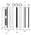
도 1a는 도면에서 사용된 평광 방향에 대한 심볼의 설명.
도 1b는 편광 그리드 스택(300)의 제 2 편광 그리드(340)가 스위치-온 상태인, 제어 가능한 슬릿 다이아프램 어레이(120) 내에서 이동 가능한 광원 열들을 가진 제 1 변형 실시예.
도 1c는 편광 그리드 스택(300)의 제 1 편광 그리드(310)가 스위치-온 상태인, 제어 가능한 슬릿 다이아프램 어레이(120) 내에서 이동 가능한 광원 열들을 가진 제 1 변형 실시예.
도 1d는 편광 그리드 스택(300)의 스위칭 가능한 반파장 플레이트(320)가 스위치-온 상태인, 제어 가능한 슬릿 다이아프램 어레이(120) 내에서 이동 가능한 광원 열들을 가진 제 1 변형 실시예.
도 1e는 편광 그리드 스택(300)의 2개의 편광 그리드(310, 340) 및 스위칭 가능한 반파장 플레이트(320)가 스위치-온 상태인, 제어 가능한 슬릿 다이아프램 어레이(120) 내에서 이동 가능한 광원 열들을 가진 제 1 변형 실시예.
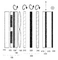
도 2는 편광 그리드 스택(300)의 제 2 편광 그리드(340)가 스위치-온 상태인, 제어 가능한 가변 편광 그리드(200)와 시야 렌즈(600)를 가진 제 2 변형 실시예.
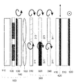
도 3a 및 도 3b는 조명 유닛(100)이 추가로 제어 가능한 상이한 광 방출 각을 갖는 제 3 변형 실시예.
도 4는 추가의 시야 렌즈(600)를 가진 제 4 변형 실시예.
도 5는 실린더 렌즈 어레이(150)에 의해 시야 렌즈 기능이 실시되도록 다이아프램이 슬릿 다이아프램 어레이(120) 내에서 조절되는 제 5 변형 실시예.
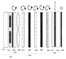
도 6은 가변 그리드 주기의 제어 가능한 편향 그리드(700)를 추가로 포함하는 제 6 변형 실시예.
도 7은 편광 그리드 스택(300) 내에 편광 그리드(310, 340) 및 반파장 플레이트(320)의 공간적 분할을 가진, 도 5와 유사한 제 7 변형 실시예.
도 8은 편광 그리드 스택(300)이 2차원 광 편향을 위한 추가의 편광 그리드(360) 및 추가의 스위칭 가능한 반파장 플레이트(350)를 포함하는, 도 5와 유사한 제 8 변형 실시예.
도 9는 2차원 광 편향을 위한 가변 그리드 주기의 추가의 제어 가능한 편향 그리드(705) 및 추가의 스위칭 가능한 또는 제어 가능한 편광 그리드 스택(305)을 포함하는, 도 6과 유사한 제 9 변형 실시예.
도 10은 편광 그리드 스택(300)이 편광 그리드들(380, 390)을 포함하고, 상기 편광 그리드들은 트위스트된 구조를 기반으로 하며 광 편향시 편광 방향을 변경하지 않는, 도 6과 유사한 제 10 변형 실시예. 1A is an illustration of a symbol for the direction of flatness used in the figure.
1B illustrates a first variant embodiment with movable light source columns within the controllable
1C shows a first variant embodiment with movable light source rows within the controllable
FIG. 1D illustrates a first variant embodiment with movable light source rows within the controllable
FIG. 1E shows a row of light sources moveable within the controllable
2 shows a second variant embodiment with a controllable
3A and 3B show a third variant embodiment with different light emission angles that the
4 shows a fourth variant embodiment with an additional field of
5 shows a fifth modified embodiment in which the diaphragm is adjusted within the
FIG. 6 illustrates a sixth variant embodiment further comprising a
FIG. 7 is a seventh variant embodiment similar to FIG. 5 with spatial division of
8 illustrates an eighth variant embodiment similar to FIG. 5, wherein the
9 is a ninth variant embodiment similar to FIG. 6, including an additional
FIG. 10 shows a tenth variation similar to FIG. 6, wherein the
도 1a는 도 1 내지 도 6에 도시된 광학 소자를 벗어나는 광의 편광 방향에 대해 도 1 내지 도 6에 사용된 심볼들을 나타낸다. 상기 심볼들은 도면에서 해당 광학 소자 위에 배치된다. 우회전 및 좌원편광 그리고 수직 및 수평 선형적 편광이 표시된다.FIG. 1A shows the symbols used in FIGS. 1-6 for the polarization direction of light that deviates from the optical element shown in FIGS. The symbols are placed on the corresponding optical element in the figure. Right and left circularly polarized light and vertical and horizontal linearly polarized light are displayed.
도 1b 내지 도 1e에는 본 발명의 제 1 변형 실시예가 개략적으로 도시된다. 방출 방향으로 제어 가능한, 시준된 조명 유닛(100)은 광원 매트릭스(110), 제어 가능한 액정 매트릭스로서 형성될 수 있는 제어 가능한 슬릿 다이아프램 어레이(120), 바람직하게는 액정 매트릭스의 출력 편광기로서 형성될 수 있는 선형적 편광 필터(130), 바람직하게는 1/4 파장 플레이트로서 형성될 수 있는, 선형적 편광으로부터 원편광을 발생시키는 복굴절 지연층(140), 및 슬릿 다이아프램으로부터 나온 광 스트라이프를 시준시키는 실린더 렌즈 어레이(150)를 포함한다. 복굴절 지연 층(140) 또는 복굴절 지연 층(140) 및 선형적 편광 필터(130)는 광 경로에서 실린더 렌즈 어레이(150) 후방에 배치된다. 순수하게 예시적으로 좌원편광된 시준된 광이 실린더 렌즈 어레이(150)를 벗어나서 편광 그리드 스택(300)에 부딪힌다. 상기 편광 그리드 스택(300)은 여기서 순수하게 예시적으로 제 1 스위칭 가능한 편광 그리드(310), 바람직하게는 스위칭 가능한 반파장 플레이트로서 형성될 수 있는 스위칭 가능한 복굴절 지연 층(320), 및 제 2 스위칭 가능한 편광 그리드(340)를 포함한다. 편광 그리드 스택(300)에 후속해서, 바람직하게는 1/4 파장 플레이트로서 형성될 수 있는 복굴절 지연 층(410)이 편광 그리드 스택을 벗어난 우원편광된 광으로부터 직선 편광된 광을 발생시키기 위해 배치된다. 후속하는 선형적 편광 필터(420)에서 상기 광은 수평 편광된 광으로 변환된다. 동시에, 스위치-온된 편광 그리드의 제로 회절 차수에서 생긴, 수직 편광된 광이 차단된다. 편광기(420)에 후속해서 공간 광 변조기(510)가 배치되고, 상기 공간 광 변조기(510)에 후속해서 순수하게 예시적으로 분석기로서 사용되는 편광 필터(530)가 배치된다. 편광기(420)는 도 2에 도시된 바와 같이, 공간 광 변조기용 분석기로서 사용된다.1B-1E schematically illustrate a first variant embodiment of the invention. The collimated
도 1b에서, 제 2 편광 그리드(340)가 스위치-온된다. 즉, 상기 회절 그리드는 활성 상태이며, 광을 관찰자의 이동 영역의 여기에 도시되지 않은 구역으로 안내한다. 상기 그리드에서는 액정 분자의 그리드형 정렬을 파괴하는 전압이 전극에 인가되지 않는다. 그리고 나서, 우원편광된 광이 제 2 스위칭 가능한 편광 그리드(340)를 벗어난다. 제 1 스위칭 가능한 편광 그리드(310) 및 스위칭 가능한 반파장 플레이트(320)가 편광 상태에 영향을 주지 않는다.In FIG. 1B, the
도 1c에서는 제 1 스위칭 가능한 편광 그리드(310)가 활성화되고, 관찰자의 이동 영역의, 상기 편광 그리드(310)에 할당된 구역을 형성한다. 여기서, 우원 광이 상기 편광 그리드(310)를 벗어나고, 상기 우원 광의 편광 방향은 후속하는 활성화되지 않은 스위칭 가능한 복굴절 지연 층(320) 및 제 2의 활성화되지 않은 스위칭 가능한 편광 그리드(340)에서 변경되지 않는다.In FIG. 1C, a first
도 1d에서는 2개의 스위칭 가능한 편광 그리드(310 및 340)가 활성화되지 않는다. 상기 광은 편향되지 않은 상태로 편광 그리드 스택(300)을 통과하고, 관찰자용 이동 영역의 제 3 구역을 형성한다. 활성화된 복굴절 지연층(320)은 여기서 좌원으로부터 우원으로 편광의 회전 방향의 필요한 회전을 일으키므로, 편광 필터(420)에서 정확한 선형적 편광 방향이 주어진다.In FIG. 1D, two
도 1e에서 2개의 편광 그리드(310 및 340)가 활성화된다. 관찰자 추적을 위해, 2개의 편광 그리드(310 및 340)의 광 편향의 조합이 사용될 수 있다. 이 경우에도 활성화된 복굴절 지연 층(320)이 편광의 회전 방향의 회전을 일으키므로, 편광 필터(420)에서 정확한 선형적 편광 방향이 주어진다.In FIG. 1E two
제어 가능한 복굴절 지연 층(320)은 우수의 편광 그리드가 활성화되면 항상 활성화된다. 제어 가능한 복굴절 지연 층(320)은 기수의 편광 그리드가 활성화되면 활성화되지 않는다. 이로 인해, 편광 그리드 스택(300) 후방에서 항상 원편광의 동일한 회전 방향이 주어진다.The controllable
도 2는 제 2 실시예를 도시한다. 여기서, 조명 유닛(100)은 순수하게 예시적으로 시준된 좌원편광된 광을 발생시킨다. 상기 광은 후속하는 제어 가능한 편광 그리드(200)를 조명하고, 상기 편광 그리드의 그리드 주기에 의해 후속하는 편광 그리드 스택(300)의 활성화된 구역에서 빔 방향이 조절된다. 상기 편광 그리드 스택(300)은 여기서도 순수하게 예시적으로 제 1 스위칭 가능한 편광 그리드(310), 스위칭 가능한 복굴절 지연 층(320) 및 제 2 스위칭 가능한 편광 그리드(340)를 포함한다. 복굴절 지연 층(410)에 후속하는 편광 필터(520)는 여기서 광 변조기(510)에 할당되고, 상기 광 변조기(510)는 마찬가지로 분석기로서 편광 필터(530)을 포함한다. 빔 경로에서 후속해서 순수하게 예시적으로 시야 렌즈(600)가 제공되고, 상기 시야 렌즈(600)는 바람직하게 평면 프레넬 렌즈로서 형성된다.2 shows a second embodiment. Here, the
도 3a 및 도 3b는 도2의 실시예와 유사한 다른 실시예를 도시한다. 도 2와는 달리, 조명 유닛(100)이 제어 가능한 상이한 광 방출 각을 갖는다. 도 3a는 제어 가능하게 조절된 광 방출 각을 화살표로 개략적으로 도시한다. 도 3b는 조명 유닛(100)의 다른, 제어 가능하게 조절된 광 방출 각을 도시한다.3A and 3B show another embodiment similar to the embodiment of FIG. 2. Unlike FIG. 2, the
이 실시예에서, 조절된 광 방출 각은 둘 다 도면 평면에 놓인다. 일반적으로 조명 유닛(100)은 예를 들면 도면 평면에 대해 수직인, 추가의 조절 가능한 광 방출 각을 가질 수 있다.In this embodiment, the adjusted light emission angles both lie in the drawing plane. In general, the
도 4는 다른 실시예를 도시한다. 도 1b 내지 도 1e에 따른 제 1 실시예와는 달리, 도 2에 따른 제 2 실시예에서와 같이 추가의 시야 렌즈(600)가 제공된다. 슬릿 다이아프램 어레이(120)로부터 나와 시야 렌즈(600)에 의해 포커싱되는 광 빔이 개략적으로 도시된다. 2개의 편광 그리드(310 및 340)는 도 1d에서와 같이 비활성 상태로 도시되므로, 광은 편향되지 않은 채로 편광 그리드 스택(300)을 통과한다.4 shows another embodiment. Unlike the first embodiment according to FIGS. 1B-1E, an
도 5에는 도 1b 내지 도 1e에 도시된 실시예에 상응하는 실시예가 도시된다. 그러나, 여기서 슬릿 다이아프램 어레이(120) 내의 다이아프램의 위치는 실린더 렌즈 어레이(150)와 조합해서, 상이한 슬릿 다이아프램으로부터 방출된 광이 하나의 공통 위치로 포커싱되도록 조절된다. 이 경우, 실린더 렌즈 어레이는 시야 렌즈 기능을 포함하므로, 도 2 내지 도 4에 따른 실시예와는 달리, 추가의 시야 렌즈가 생략될 수 있다. 여기서도, 2개의 편광 그리드(310) 및 (340)가 도 1d에서와 같이 비-활성 상태로 도시되므로, 광이 편향되지 않고 편광 그리드 스택(300)을 통과한다.FIG. 5 shows an embodiment corresponding to the embodiment shown in FIGS. 1B-1E. However, here the position of the diaphragm in the
도 6은 도 2와 유사한 실시예를 도시한다. 도 2에 추가해서, 도 6은 가변 그리드 주기의 제어 가능한 편향 그리드(700)를 포함한다. 이 실시예에서, 그리드는 편광 그리드 스택(300), 광 변조기(510) 및 시야 렌즈(600)의 후방에 배치된다. 편광 그리드 스택(300)의 제 2 편광 그리드(340)가 도 1b와 유사하게 활성화되는 것이 도시된다. 이러한 가변 편향 그리드(700)는 추가의 미세 단계의 광 편향 및/또는 편광 그리드 스택(300) 내에서 광 편향의 파장 의존성의 보상을 가능하게 한다.FIG. 6 shows an embodiment similar to FIG. 2. In addition to FIG. 2, FIG. 6 includes a
가변 편향 그리드가 편광 그리드 스택(300) 전방에 또는 편광 그리드 스택(300)의 2개의 개별 부품(310, 320, 340) 사이에 배치될 수도 있다. 편향 그리드의 기능은 빔 경로의 상이한 위치에 배치될 수 있는 복수의 부품으로 분할될 수 있다.A variable deflection grid may be disposed in front of the
도 7은 도 5와 유사한 다른 실시예를 도시한다. 이 경우, 편광 그리드(310 및 340) 그리고 스위칭 가능한 반파장 플레이트(320)는 복수의 별도로 스위칭 가능한 세그먼트로 분할된다. 도시된 실시예에서, 순수하게 예시적으로 각각의 광학 부품(310, 320, 340)이 2개의 세그먼트(311, 312, 321, 322, 341, 342)로 분할된다. 편광 그리드(310)는 상부 세그먼트(312)에서 활성화된 상태로 도시되며, 스위칭 가능한 반파장 플레이트(320)는 하부 세그먼트에서 활성화된 상태로 도시된다. 편광 그리드 스택(300) 후방에서, 방출 편광 상태는 2개의 세그먼트에서 동일하지만, 편향 각은 상부 및 하부 세그먼트에서 상이하다. 상기 분할은 확장된 디스플레이에서 광이 관찰자를 추적하기 위해 사용될 수 있다. 분할은 2차원으로 또는 예를 들면 동심으로 이루어질 수 있다.FIG. 7 shows another embodiment similar to FIG. 5. In this case, the
도 8은 도 5와 유사한 변형 실시예를 도시한다. 도 5와는 달리, 편광 그리드 스택은 추가의 스위칭 가능한 반파장 플레이트(350) 및 추가의 편광 그리드(360)를 포함한다. 도면에서, 상기 소자들은 활성화된 상태로 도시된다. 편광 그리드(350) 내에서 그리드 구조는 편광 그리드(310 및 340)에 비해 90도 회전된 상태로 배치된다. 이로 인해, 편향 방향이 그리드(310 및 340)의 편향 방향에 비해 90도 회전된다. 이러한 편광 그리드 스택은 예를 들면 2개의 방향으로 제어 가능한, 구형 렌즈(155)와 사각형 또는 둥근 다이아프램의 어레이(125)의 2차원 배치와 조합해서 사용될 수 있다. 따라서, 관찰자 추적이 수평 및 수직 방향으로 가능하다.FIG. 8 shows a variant embodiment similar to FIG. 5. Unlike FIG. 5, the polarization grid stack includes an additional
2개의 편광 그리드(310, 340)의 그리드 구조는 편광 그리드(350)의 그리드 구조에 대해 수직으로 배치될 필요는 없고, 오히려 편향이 2개의 임의로 선택된 방향으로 이루어질 수 있도록 배치될 수 있다.The grid structure of the two
2개의 방향으로 제어 가능한, 다른 조명 장치들(100)도 사용될 수 있다.
도 9는 도 6과 유사한 변형 실시예를 도시하지만, 추가로 제 2 스위칭 가능한 또는 제어 가능한 편광 그리드 스택(305)을 포함하고, 상기 편광 그리드 스택(305) 내의 도시된 스위칭 가능한 또는 제어 가능한 편광 그리드(315, 345)의 그리드 구조는 편광 그리드 스택(300) 내의 2개의 편광 그리드(310, 340)의 그리드 구조에 비해 회전되어 있다. 이 실시예는 가변 그리드 주기의 2개의 제어 가능한 편향 그리드(700 및 705)를 포함한다. 편향 그리드 스택(305)에는 순수하게 예시적으로 가변 그리드 주기를 가진 추가의 제어 가능한 편향 그리드(705)가 할당되며, 상기 편향 그리드의 회절 방향은 편광 그리드 스택(305)의 회절 방향에 맞춰진다. 가변 그리드 주기의 제어 가능한 편향 그리드(700)는 편광 그리드(300)에 할당되며, 그것의 편향 방향에 맞춰진다. 순수하게 예시적으로, 상기 편향 그리드는 2개의 편향 그리드 스택(300, 305) 사이에 배치된다. 편향 그리드(700)는 예를 들면 수평 광 편향을 위해 그리고 그리드(705)는 수직 광 편향을 위해 사용된다. 가변 편향 그리드들(700 및 705)은 편광 그리드 스택들(300 및 305)에서 추가의 미세 단계의 광 편향 및/또는 광 편향의 파장 의존성의 보상을 가능하게 한다.FIG. 9 shows a variant embodiment similar to FIG. 6, but further comprising a second switchable or controllable
도 1 내지 도 9의 변형 실시예들은 종래의 편광 그리드의 사용에 관한 것이다. 편광 그리드들은 입사광의 편광을 예를 들면 좌원으로부터 우원으로 변경하는 특성을 갖는다.1 to 9 relate to the use of a conventional polarization grid. Polarizing grids have the property of changing the polarization of incident light, for example, from a left circle to a right circle.
도 10은 편광 그리드 스택(300)이 스위칭 가능한 또는 제어 가능한 편광 그리드들(370, 380)을 포함하는 본 발명의 변형 실시예를 도시하며, 상기 편광 그리드들은 주기적으로 트위스트된 구조를 기반으로 하고, 상기 편광 그리드를 통과하는 광은 그 편광의 회전 방향을 유지한다. 이 변형 실시예는 도 6과 유사하게 구성된다. 그러나, 편광 그리드 스택(300)의 제 1 편광 그리드(370)는 활성화된 상태로 도시된다. 즉, 광은 회절되어 편향된 상태로 상기 편광 그리드를 통과한다. 광이 상기 편광 그리드(370)를 통과할 때, 광은 여기서 비-활성화된 상태로 도시된 제 2 편광 그리드(380)를 통과할 때와 마찬가지로 편광의 회전 방향을 유지하므로, 광에서 추가의 광 편향이 나타나지 않는다.FIG. 10 illustrates a variant embodiment of the present invention in which the
단 하나의 편향 방향이 사용되어야 하면, 즉 각각의 그리드(370, 380)에 대해 단 하나의 고정 입력 편광이 선택되어야 하면, 2개의 연속하는 스위칭 가능한 또는 제어 가능한 편광 그리드(370, 380) 사이의 스위칭 가능한 또는 제어 가능한 지연 층이 도 10에 순수하게 예시적으로 도시된 바와 같이, 생략될 수 있다. 여기서 사용된 편광 그리드들(370, 380)이 광 통과시 편광의 회전 방향을 변경시키지 않기 때문에, 바람직하게는 상기 변형 실시예에서, 층 스택 내에 동일한 트위스트의 편광 그리드가 사용되면 편광 그리드들(370, 380) 사이에 편광 회전 층들이 필요없다. 이 실시예에서 조명 유닛(100)은 우원편광된 광을 발생시킨다. 상기 우원편광 상태는 2개의 편광 그리드(370, 380)를 통과할 때 유지된다. 직선 편광된 광을 필요로 하는 공간 광 변조기(510)에 대해, 도 6에서와 같이 복굴절 지연 층(410)이 포함될 수 있고, 선형적 편광기(520)에 의해 제로 회절 차수의 바람직하지 않은 산란 광이 억제될 수 있다.If only one deflection direction should be used, i.e. only one fixed input polarization should be selected for each grid 370,380, between two successive switchable or controllable polarization grids 370,380 A switchable or controllable delay layer may be omitted, as purely illustrated in FIG. 10. Since the
끝으로, 전술한 실시예들은 청구된 사상을 나타내기 위해서만 사용되며, 상기 사상이 실시예들에 제한되지 않는다. 특히, 전술한 실시예들은 가능한 한 서로 조합될 수 있다.Finally, the foregoing embodiments are only used to represent the claimed idea, and the idea is not limited to the embodiments. In particular, the above-described embodiments can be combined with each other as much as possible.
100
조명 유닛
110
광원 매트릭스
120
제어 가능한 슬릿 다이아프램 어레이
125
제어 가능한 다이아프램 어레이
130
편광 필터
140
복굴절 지연 층
150
실린더 렌즈 어레이
155
렌즈 어레이
200
가변 제어 가능한 편광 그리드
300
편광 그리드 스택
305
회전된 편광 그리드 스택
310
제 1 스위칭 가능한 편광 그리드
311
제 1 스위칭 가능한 편광 그리드의 제 1 세그먼트
312
제 1 스위칭 가능한 편광 그리드의 제 2 세그먼트
315
회전된 편광 그리드 스택 내의 제 1 스위칭 가능한 편광 그리드
320
스위칭 가능한 복굴절 지연 층
321
스위칭 가능한 복굴절 지연 층의 제 1 세그먼트
322
스위칭 가능한 복굴절 지연 층의 제 2 세그먼트
325
회전된 편광 그리드 스택 내의 스위칭 가능한 복굴절 지연 층
335
회전된 편광 그리드 스택 내의 스위칭 가능한 복굴절 지연 층
340
제 2 스위칭 가능한 편광 그리드
341
제 2 스위칭 가능한 편광 그리드의 제 1 세그먼트
342
제 2 스위칭 가능한 편광 그리드의 제 2 세그먼트
345
회전된 편광 그리드 스택 내의 제 2 스위칭 가능한 편광 그리드
350
스위칭 가능한 복굴절 지연 층
360
회전된 스위칭 가능한 편광 그리드
370
제 1 편광 방향을 얻는 스위칭 가능한 편광 그리드
380
제 2 편광 방향을 얻는 스위칭 가능한 편광 그리드
410
복굴절 지연 층
420
선형적 편광 필터
510
공간 광 변조기
520
선형적 편광 필터
530
선형적 편광 필터
600
시야 렌즈
700
제어 가능한 편향 그리드
705
회전된 제어 가능한 편향 그리드100 lighting units
110 light source matrix
120 Controllable Slit Diaphragm Array
125 Controllable Diaphragm Array
130 polarizing filter
140 birefringent retardation layer
150 cylinder lens array
155 lens array
200 variable controllable polarization grids
300 polarized grid stack
305 rotated polarized grid stack
310 first switchable polarizing grid
311 first segment of first switchable polarizing grid
312 second segment of first switchable polarizing grid
First switchable polarization grid in 315 rotated polarization grid stack
320 switchable birefringent delay layer
321 first segment of switchable birefringent delay layer
322 second segment of the switchable birefringent delay layer
Switchable birefringent retardation layer in a 325 rotated polarization grid stack
Switchable birefringent delay layer in a 335 rotated polarization grid stack
340 second switchable polarizing grid
341 first segment of second switchable polarizing grid
342 second segment of the second switchable polarizing grid
345 second switchable polarization grid in a rotated polarization grid stack
350 switchable birefringent delay layer
360 rotated switchable polarized grid
370 Switchable polarization grid to obtain first polarization direction
380 switchable polarization grid to obtain second polarization direction
410 birefringent retardation layer
420 linear polarized filters
510 spatial light modulator
520 linearly polarized filters
530 linear polarization filters
600 field of view lens
700 controllable deflection grid
705 rotated controllable deflection grid
Claims (25)
홀로그래픽적으로 인코딩된 물체의 재구성 또는 이미지 뷰가 적어도 하나의 관찰자의 관련된 눈의 이동에 대해 추적될 수 있고,
상기 디스플레이는,
- 광을 발생시키기 위한 조명 유닛;
- 광 편향을 위한 적어도 2개의 스위칭 가능한 또는 제어 가능한 편광 그리드를 포함하는 광학 부품의 스택을 갖는 적어도 하나의 편광 그리드 스택;
- 이미지 정보를 디스플레이하기 위해 또는 인코딩된 홀로그램 정보를 재구성하기 위해 상기 조명 유닛의 광을 변조하는 공간 광 변조기;
- 상기 스위칭 가능한 또는 제어 가능한 편광 그리드, 상기 조명 유닛, 및 공간 광 변조기를 구동 및 동기화하는 시스템 제어부;
- 추가적인 미세 단계의 광 편향을 가능하게 하는 가변 그리드 주기를 갖는 적어도 하나의 제어 가능한 편향 그리드를 포함하고,
- 관찰자의 눈의 현재 위치에 따라, 상기 조명 유닛, 상기 편광 그리드 스택, 및 상기 제어 가능한 편향 그리드 중 적어도 하나는, 상기 조명 유닛의 광이 상기 관찰자의 눈의 방향으로 편향될 수 있도록, 상기 시스템 제어부에 의해 구동될 수 있는 것인, 디스플레이.Displays, especially for autostereoscopic or holographic displays,
A reconstruction or image view of the holographically encoded object can be tracked for the movement of the eye of the at least one observer,
The display,
An illumination unit for generating light;
At least one polarization grid stack having a stack of optical components comprising at least two switchable or controllable polarization grids for light deflection;
A spatial light modulator for modulating the light of said lighting unit for displaying image information or for reconstructing encoded hologram information;
A system control unit for driving and synchronizing said switchable or controllable polarization grid, said illumination unit and spatial light modulator;
At least one controllable deflection grid with variable grid periods to enable additional fine step optical deflection,
At least one of the illumination unit, the polarization grid stack, and the controllable deflection grid, depending on the current position of the observer's eye, allows the light of the illumination unit to be deflected in the direction of the observer's eye. A display, which can be driven by the control unit.
상기 편광 그리드 스택은, 광학 부품으로서 적어도 하나의 스위칭 가능한 또는 제어 가능한 복굴절 지연(birefringent retardation) 층을 더 포함하는 것인, 디스플레이.The method of claim 1,
Wherein the polarization grid stack further comprises at least one switchable or controllable birefringent retardation layer as an optical component.
상기 제어 가능한 복굴절 지연 층은 경사진 빔 통과시 광 경로 길이의 분산 효과 또는 변화를 보상하기 위해 제공되는 것인, 디스플레이.The method of claim 2,
And the controllable birefringent retardation layer is provided to compensate for the dispersion effect or change in optical path length upon passing the inclined beam.
상기 편광 그리드 스택의 후방에, 원편광된 광(circularly polorized light)을 직선 편광된 광(linearly polarized light)으로 변환하기 위해 추가의 복굴절 지연 층이 배치되는 것인, 디스플레이.The method according to claim 1 or 2,
At the rear of the polarization grid stack, an additional birefringent retardation layer is disposed to convert circularly polarized light into linearly polarized light.
상기 추가의 복굴절 지연 층의 후방에 편광 필터가 배치되고, 상기 편광 필터는 스위치-온된 편광 그리드의 제로차 회절 차수의 직선 편광된 광을 억제하는 것인, 디스플레이.The method of claim 4, wherein
And a polarization filter disposed behind the further birefringent retardation layer, wherein the polarization filter suppresses linearly polarized light of zero order diffraction orders of the switched-on polarization grid.
상기 가변 그리드 주기를 갖는 제어 가능한 편향 그리드는 상기 편광 그리드 스택의 전방에 또는 후방에 또는 그 내에 배치되는 것인, 디스플레이.The method according to claim 1 or 2,
And a controllable deflection grid having the variable grid period is disposed in front of or behind or in the polarizing grid stack.
상기 제어 가능한 편향 그리드는 상기 편광 그리드 스택의 스위칭 가능한 편광 그리드의 편향 각의 파장 의존성을 보상하기 위해 사용가능한 것인, 디스플레이.The method of claim 6,
And the controllable deflection grid is usable to compensate for wavelength dependence of the deflection angle of the switchable polarization grid of the polarization grid stack.
상기 제어 가능한 편향 그리드는 인가되는 전압 프로파일의 주기를 변화시킴으로써 시야 렌즈(field lens) 기능을 얻거나 또는 지원하기 위해 사용가능한 것인, 디스플레이.The method of claim 6,
And the controllable deflection grid is usable to obtain or support field lens functionality by varying the period of the applied voltage profile.
회절 유효성(diffraction effectiveness)이 결정가능한 값으로 변화될 수 있도록, 제어 가능한 편광 그리드에 인가되는 전압이 맞춰질 수 있는(adaptable) 것인, 디스플레이.The method of claim 1,
Wherein the voltage applied to the controllable polarization grid is adaptable such that the diffraction effectiveness can be changed to a determinable value.
상기 조명 유닛은 제어 가능한 상이한 광 방출 각을 갖는 것인, 디스플레이.The method according to claim 1 or 2,
Wherein the illumination unit has a controllable different light emission angle.
상기 편광 그리드 스택 내의 적어도 하나의 광학 부품은 하나 또는 2개의 방향으로 분할되어(segmented) 구현되고, 개별 세그먼트는 개별적으로 스위칭 가능하거나 또는 제어 가능한 것인, 디스플레이.The method according to claim 1 or 2,
Wherein the at least one optical component in the polarization grid stack is implemented segmented in one or two directions, wherein the individual segments are individually switchable or controllable.
개별 세그먼트는 추가의 시야 렌즈 기능을 형성하거나 또는 지원하기 위해 상이한 편향 각을 실시하는 것인, 디스플레이.The method of claim 1,
Wherein the individual segments implement different deflection angles to form or support additional viewing lens functionality.
상기 편광 그리드 스택 내의 적어도 하나의 편광 그리드의 그리드 구조는 서로에 대해 회전되어 배치되거나, 또는
상기 디스플레이는 제 2 편광 그리드 스택을 포함하고, 상기 제 2 편광 그리드 스택에서 그리드 구조는 상기 편광 그리드 스택의 그리드 구조에 대해 서로 일정한 각만큼 회전되는 것인, 디스플레이.The method according to claim 1 or 2,
The grid structures of at least one polarization grid in the polarization grid stack are arranged rotated relative to each other, or
Wherein the display comprises a second polarization grid stack, wherein the grid structures in the second polarization grid stack are rotated by a constant angle with respect to the grid structure of the polarization grid stack.
상기 편광 그리드 스택은 적어도 하나의 스위칭 가능한 또는 제어 가능한 편광 그리드를 포함하고, 상기 편광 그리드를 통과할 때 상기 편광 그리드에서 광의 회전 방향이 유지되는 것인, 디스플레이.The method according to claim 1 or 2,
Wherein the polarization grid stack comprises at least one switchable or controllable polarization grid, wherein the direction of rotation of light in the polarization grid is maintained when passing through the polarization grid.
상기 편광 그리드 스택은 상기 조명 유닛과 상기 공간 광 변조기 사이의 광 경로 내에 또는 광의 전파방향에서 보았을 때 상기 공간 광 변조기의 배후에 배치되는 것인, 디스플레이.The method according to claim 1 or 2,
Wherein the polarization grid stack is disposed in the optical path between the illumination unit and the spatial light modulator or behind the spatial light modulator when viewed in the direction of propagation of light.
상기 적어도 하나의 관찰자의 관련된 눈의 위치를 결정하는 인식 시스템을 더 포함하는, 디스플레이.The method of claim 1,
And a recognition system for determining the position of an associated eye of the at least one observer.
상기 조명 유닛의 광원은, 개별적으로 또는 열들로 스위칭 가능한 또는 제어 가능한 광원 매트릭스로서 1차 광원의 어레이 내에 배치되는 것인, 디스플레이.The method according to claim 1 or 2,
The light source of the lighting unit is disposed in the array of primary light sources individually or as a switchable or controllable light source matrix in columns.
상기 조명 유닛의 광원은 LED, OLED, 또는 레이저 광원인 것인, 디스플레이.The method according to claim 1 or 2,
The light source of said lighting unit is a LED, OLED, or a laser light source.
상기 조명 유닛의 광원은 그 방출 특성의 상이한 중심 파장을 갖는 복수의 별도로 작동 가능한 개별 광원들로 이루어지는 것인, 디스플레이.The method according to claim 1 or 2,
Wherein the light source of the illumination unit consists of a plurality of separately operable individual light sources having different center wavelengths of their emission characteristics.
상기 조명 유닛은 슬릿 다이아프램의 스위칭 가능한 또는 제어 가능한 어레이를 포함하는 것인, 디스플레이.The method according to claim 1 or 2,
Wherein said lighting unit comprises a switchable or controllable array of slit diaphragms.
상기 슬릿 다이아프램의 어레이는 LCD-다이아프램 어레이로서 구현되는 것인, 디스플레이.The method of claim 20,
Wherein the array of slit diaphragms is implemented as an LCD-diaphragm array.
상기 조명 유닛은 시준을 위한 실린더 렌즈 어레이를 포함하는 것인, 디스플레이.The method according to claim 1 or 2,
Wherein said illumination unit comprises a cylinder lens array for collimation.
상기 실린더 렌즈 어레이는 시야 렌즈 기능을 더 포함하는 것인, 디스플레이.The method of claim 22,
And the cylinder lens array further comprises a field of view lens function.
상기 조명 유닛의 광은 미리 정해질 수 있는 원편광(circular polarization)을 갖는 것인, 디스플레이.The method according to claim 1 or 2,
Wherein the light of the illumination unit has a circular polarization which can be predetermined.
상기 조명 유닛과 상기 관찰자 사이의 빔 경로 내에 추가의 고정 또는 가변 시야 렌즈가 포함되는 것인, 디스플레이.The method according to claim 1 or 2,
And a further fixed or variable field of view lens is included in the beam path between the illumination unit and the viewer.
Priority Applications (1)
| Application Number | Priority Date | Filing Date | Title |
|---|---|---|---|
| KR1020207017042A KR102254617B1 (en) | 2012-01-26 | 2013-01-25 | Display with observer tracking |
Applications Claiming Priority (5)
| Application Number | Priority Date | Filing Date | Title |
|---|---|---|---|
| DE102012201166 | 2012-01-26 | ||
| DE102012201166.8 | 2012-01-26 | ||
| DE102012105479.7 | 2012-06-22 | ||
| DE102012105479 | 2012-06-22 | ||
| PCT/EP2013/051423 WO2013110748A1 (en) | 2012-01-26 | 2013-01-25 | Display with observer tracking |
Related Parent Applications (1)
| Application Number | Title | Priority Date | Filing Date |
|---|---|---|---|
| KR1020147023673A Division KR102015590B1 (en) | 2012-01-26 | 2013-01-25 | Display with observer tracking |
Related Child Applications (1)
| Application Number | Title | Priority Date | Filing Date |
|---|---|---|---|
| KR1020207017042A Division KR102254617B1 (en) | 2012-01-26 | 2013-01-25 | Display with observer tracking |
Publications (2)
| Publication Number | Publication Date |
|---|---|
| KR20190101502A true KR20190101502A (en) | 2019-08-30 |
| KR102124632B1 KR102124632B1 (en) | 2020-06-22 |
Family
ID=47664264
Family Applications (3)
| Application Number | Title | Priority Date | Filing Date |
|---|---|---|---|
| KR1020197024666A KR102124632B1 (en) | 2012-01-26 | 2013-01-25 | Display with observer tracking |
| KR1020207017042A KR102254617B1 (en) | 2012-01-26 | 2013-01-25 | Display with observer tracking |
| KR1020147023673A KR102015590B1 (en) | 2012-01-26 | 2013-01-25 | Display with observer tracking |
Family Applications After (2)
| Application Number | Title | Priority Date | Filing Date |
|---|---|---|---|
| KR1020207017042A KR102254617B1 (en) | 2012-01-26 | 2013-01-25 | Display with observer tracking |
| KR1020147023673A KR102015590B1 (en) | 2012-01-26 | 2013-01-25 | Display with observer tracking |
Country Status (5)
| Country | Link |
|---|---|
| US (2) | US9529430B2 (en) |
| KR (3) | KR102124632B1 (en) |
| CN (2) | CN107664838B (en) |
| TW (1) | TWI596380B (en) |
| WO (1) | WO2013110748A1 (en) |
Families Citing this family (63)
| Publication number | Priority date | Publication date | Assignee | Title |
|---|---|---|---|---|
| CN105446048B (en) * | 2014-05-27 | 2017-06-20 | 华为技术有限公司 | Adjustable optical attenuator |
| CN104330952A (en) * | 2014-11-10 | 2015-02-04 | 电子科技大学 | 2D/3D switchable display device |
| EP3291001B1 (en) * | 2015-04-27 | 2021-10-20 | National Institute of Advanced Industrial Science and Technology | Light beam deflecting element, wavelength-selective cross-connect device using same, and optical cross-connect device |
| EP3369034B1 (en) | 2015-10-26 | 2023-07-05 | RealD Spark, LLC | Intelligent privacy system, apparatus, and method thereof |
| US20170299941A1 (en) * | 2016-04-13 | 2017-10-19 | Boulder Nonlinear Systems, Inc. | Compact liquid crystal beam steering devices including multiple polarization gratings |
| CN114554177A (en) | 2016-05-19 | 2022-05-27 | 瑞尔D斯帕克有限责任公司 | Wide-angle imaging directional backlight source |
| CN105954992B (en) * | 2016-07-22 | 2018-10-30 | 京东方科技集团股份有限公司 | Display system and display methods |
| US10901205B1 (en) | 2016-08-09 | 2021-01-26 | Facebook Technologies, Llc | Focus adjusting liquid crystal lenses in a head-mounted display |
| US10108144B2 (en) * | 2016-09-16 | 2018-10-23 | Microsoft Technology Licensing, Llc | Holographic wide field of view display |
| US10379419B1 (en) | 2016-11-23 | 2019-08-13 | Facebook Technologies, Llc | Focus adjusting pancharatnam berry phase liquid crystal lenses in a head-mounted display |
| WO2018110431A1 (en) * | 2016-12-13 | 2018-06-21 | 国立研究開発法人産業技術総合研究所 | Optical beam deflection element and module |
| US10151961B2 (en) * | 2016-12-29 | 2018-12-11 | Facebook Technologies, Llc | Switchable bragg gratings for chromatic error correction of pancharatnam berry phase (PBP) components |
| CN106646954B (en) * | 2017-03-02 | 2019-09-13 | 京东方科技集团股份有限公司 | A kind of peep-proof display and liquid crystal display device |
| US10126575B1 (en) | 2017-05-08 | 2018-11-13 | Reald Spark, Llc | Optical stack for privacy display |
| WO2018208619A1 (en) | 2017-05-08 | 2018-11-15 | Reald Spark, Llc | Optical stack for directional display |
| CN107132690B (en) * | 2017-07-03 | 2020-02-21 | 上海交通大学 | Naked eye 3D system |
| JP6614209B2 (en) * | 2017-07-26 | 2019-12-04 | セイコーエプソン株式会社 | Liquid crystal display device and electronic device |
| TW201921060A (en) | 2017-09-15 | 2019-06-01 | 美商瑞爾D斯帕克有限責任公司 | Optical stack for switchable directional display |
| US10948648B2 (en) | 2017-09-29 | 2021-03-16 | Reald Spark, Llc | Backlights having stacked waveguide and optical components with different coefficients of friction |
| WO2019090246A1 (en) | 2017-11-06 | 2019-05-09 | Reald Spark, Llc | Privacy display apparatus |
| AU2019211358A1 (en) | 2018-01-25 | 2020-09-24 | Reald Spark, Llc | Reflective optical stack for privacy display |
| JP7353007B2 (en) | 2018-01-25 | 2023-09-29 | リアルディー スパーク エルエルシー | Touch screen for privacy display |
| KR20200141459A (en) | 2018-03-22 | 2020-12-18 | 리얼디 스파크, 엘엘씨 | Optical waveguide for directional backlight |
| CN112166372A (en) * | 2018-03-26 | 2021-01-01 | 视瑞尔技术公司 | Display device |
| EP3814832A4 (en) | 2018-06-29 | 2022-04-06 | RealD Spark, LLC | Stabilization for privacy display |
| US10951875B2 (en) | 2018-07-03 | 2021-03-16 | Raxium, Inc. | Display processing circuitry |
| US11073735B2 (en) | 2018-07-18 | 2021-07-27 | Reald Spark, Llc | Optical stack for switchable directional display |
| EP3844949A1 (en) * | 2018-08-29 | 2021-07-07 | PCMS Holdings, Inc. | Optical method and system for light field displays based on mosaic periodic layer |
| US10983262B2 (en) | 2018-09-20 | 2021-04-20 | Hong Kong Applied Science and Technology Research Institute Company Limited | Rotational geometric phase hologram with application for fabricating geometric phase optical element |
| CN109643025B (en) * | 2018-09-20 | 2021-02-02 | 香港应用科技研究院有限公司 | Rotational geometric phase holograms with application for fabrication of GPOE |
| WO2020072643A1 (en) | 2018-10-03 | 2020-04-09 | Reald Spark, Llc | Privacy display control apparatus |
| CN113167953B (en) * | 2018-11-07 | 2023-10-24 | 瑞尔D斯帕克有限责任公司 | Directional display device |
| WO2020146091A1 (en) | 2019-01-07 | 2020-07-16 | Reald Spark, Llc | Optical stack for privacy display |
| US10663776B1 (en) * | 2019-01-31 | 2020-05-26 | Sharp Kabushiki Kaisha | Enhanced privacy switchable backlight system |
| CN113646695A (en) | 2019-02-12 | 2021-11-12 | 瑞尔D斯帕克有限责任公司 | Diffuser for a privacy display |
| EP3928148A4 (en) * | 2019-02-18 | 2023-01-11 | Rnvtech Ltd | High resolution 3d display |
| TW202102883A (en) | 2019-07-02 | 2021-01-16 | 美商瑞爾D斯帕克有限責任公司 | Directional display apparatus |
| EP4007930A4 (en) | 2019-08-02 | 2023-08-30 | RealD Spark, LLC | Optical stack for privacy display |
| US11024681B2 (en) * | 2019-08-15 | 2021-06-01 | Sharp Kabushiki Kaisha | Parallax optics for top emitting electroluminescent displays |
| US11609429B2 (en) * | 2019-08-22 | 2023-03-21 | Htc Corporation | Display device |
| US11114063B2 (en) | 2019-10-02 | 2021-09-07 | Reald Spark, Llc | Privacy display apparatus |
| JP2023500234A (en) | 2019-11-01 | 2023-01-05 | ラキシウム インコーポレイテッド | Brightfield displays incorporating eye trackers and methods for using eye-tracking information to generate views for brightfield displays |
| US11079646B2 (en) | 2019-11-13 | 2021-08-03 | Reald Spark, Llc | Display device off-axis luminance reduction uniformity |
| EP4073560A4 (en) | 2019-12-10 | 2024-02-21 | Reald Spark Llc | Control of reflections of a display device |
| CN114902093A (en) | 2019-12-18 | 2022-08-12 | 瑞尔D斯帕克有限责任公司 | Control of ambient light for privacy display |
| CN115087906A (en) | 2020-02-06 | 2022-09-20 | 威尔乌集团 | Spatially time-varying polarization correcting optics for scanned beam systems |
| EP4116746A4 (en) * | 2020-03-05 | 2024-03-27 | Wuhan China Star Optoelectronics Semiconductor Display Tech Co Ltd | Polarizer sheet and display panel |
| CN111198449B (en) * | 2020-03-13 | 2021-04-13 | 联想(北京)有限公司 | Electronic device and control method thereof |
| CN111578867B (en) * | 2020-04-10 | 2021-08-24 | 清华大学深圳国际研究生院 | Three-dimensional imaging method and system based on multiple-time dislocation compression holographic reconstruction |
| EP4143631A1 (en) | 2020-04-30 | 2023-03-08 | RealD Spark, LLC | Directional display apparatus |
| CN115768643A (en) | 2020-04-30 | 2023-03-07 | 瑞尔D斯帕克有限责任公司 | Directional display device |
| CN115735144A (en) | 2020-04-30 | 2023-03-03 | 瑞尔D斯帕克有限责任公司 | Directional display device |
| TW202204818A (en) | 2020-07-29 | 2022-02-01 | 美商瑞爾D斯帕克有限責任公司 | Pupillated illumination apparatus |
| EP4189285A1 (en) | 2020-07-29 | 2023-06-07 | RealD Spark, LLC | Backlight for switchable directional display |
| WO2022170207A1 (en) * | 2021-02-05 | 2022-08-11 | Boulder Nonlinear Systems, Inc. | Reducing stray light in beam steering systems using polarization gratings |
| WO2022170135A1 (en) * | 2021-02-05 | 2022-08-11 | Boulder Nonlinear Systems, Inc. | Simultaneous focusing of an optical system to multiple focal planes using liquid crystal polarization lenses |
| WO2022166985A1 (en) * | 2021-02-08 | 2022-08-11 | University Of Central Florida Research Foundation, Inc. | Optical display system with exit pupil steering |
| TWI770949B (en) * | 2021-04-20 | 2022-07-11 | 達運精密工業股份有限公司 | Display device, non-contact key and input device |
| CN113325601B (en) * | 2021-08-03 | 2021-10-26 | 成都工业学院 | High-viewpoint and high-density light field stereoscopic display device |
| US11892717B2 (en) | 2021-09-30 | 2024-02-06 | Reald Spark, Llc | Marks for privacy display |
| CN114460758A (en) * | 2022-02-17 | 2022-05-10 | 中山大学 | Polarized light type directional backlight naked eye 3D display system |
| US11892718B2 (en) | 2022-04-07 | 2024-02-06 | Reald Spark, Llc | Directional display apparatus |
| CN115981026B (en) * | 2023-03-22 | 2023-05-12 | 成都工业学院 | Crosstalk-free grating stereoscopic display |
Citations (2)
| Publication number | Priority date | Publication date | Assignee | Title |
|---|---|---|---|---|
| KR20070084438A (en) * | 2004-11-24 | 2007-08-24 | 코닌클리케 필립스 일렉트로닉스 엔.브이. | Display device |
| WO2010149587A2 (en) * | 2009-06-23 | 2010-12-29 | Seereal Technologies S.A. | Light modulation device for a display for representing two- and/or three-dimensional image content |
Family Cites Families (18)
| Publication number | Priority date | Publication date | Assignee | Title |
|---|---|---|---|---|
| US6188462B1 (en) * | 1998-09-02 | 2001-02-13 | Kent State University | Diffraction grating with electrically controlled periodicity |
| DE50311875D1 (en) | 2002-11-13 | 2009-10-15 | Seereal Technologies Gmbh | DEVICE FOR RECONSTRUCTING VIDEOHOLOGRAMS |
| DE10339076B4 (en) | 2003-08-26 | 2007-10-31 | Seereal Technologies Gmbh | Autostereoscopic multi-user display |
| DE10359403B4 (en) * | 2003-12-18 | 2005-12-15 | Seereal Technologies Gmbh | Autostereoscopic multi-user display |
| CN1301420C (en) * | 2004-03-25 | 2007-02-21 | 南京大学 | Double-micro-polarizing free stereo imaging device and method thereof |
| DE102004044111B4 (en) | 2004-09-08 | 2015-05-07 | Seereal Technologies Gmbh | Method and device for coding and reconstructing computer-generated video holograms |
| KR100703701B1 (en) | 2005-06-14 | 2007-04-06 | 삼성전자주식회사 | Method and apparatus for providing tactile information effectively |
| US7791813B2 (en) | 2006-10-12 | 2010-09-07 | Honeywell International Inc. | Microfluidic imaging array |
| DE102007024236A1 (en) | 2007-05-21 | 2008-11-27 | Seereal Technologies S.A. | Holographic reconstruction system with an array of controllable microprisms |
| DE102007026071A1 (en) | 2007-05-24 | 2008-11-27 | Seereal Technologies S.A. | Direction-controlled lighting unit for an autostereoscopic display |
| US8531646B2 (en) | 2007-09-11 | 2013-09-10 | Kent State University | Tunable liquid crystal devices, devices using same, and methods of making and using same |
| GB2457690A (en) * | 2008-02-21 | 2009-08-26 | Sharp Kk | Viewer position tracking display |
| GB0901084D0 (en) * | 2009-01-22 | 2009-03-11 | Trayner David J | Autostereoscopic display |
| WO2010136762A1 (en) * | 2009-05-28 | 2010-12-02 | Milan Momcilo Popovich | Apparatus for providing a 3d display |
| DE112010003840B4 (en) * | 2009-09-29 | 2022-10-20 | Seereal Technologies S.A. | Light modulator for a display, display and a method for operating a light modulator |
| CN202058394U (en) * | 2011-04-15 | 2011-11-30 | 黑龙江省四维影像数码科技有限公司 | Three-dimensional free stereoscopic display electronic album |
| US8964138B2 (en) * | 2012-02-03 | 2015-02-24 | Samsung Electronics Co., Ltd. | Glass apparatus for watching polarized image |
| CN102799024A (en) * | 2012-08-09 | 2012-11-28 | 深圳市华星光电技术有限公司 | Two-dimensional/three-dimensional image switchable liquid crystal display |
-
2013
- 2013-01-25 KR KR1020197024666A patent/KR102124632B1/en active IP Right Grant
- 2013-01-25 CN CN201710581299.8A patent/CN107664838B/en active Active
- 2013-01-25 CN CN201380017237.4A patent/CN104204926B/en active Active
- 2013-01-25 WO PCT/EP2013/051423 patent/WO2013110748A1/en active Application Filing
- 2013-01-25 KR KR1020207017042A patent/KR102254617B1/en active IP Right Grant
- 2013-01-25 KR KR1020147023673A patent/KR102015590B1/en active Application Filing
- 2013-01-25 US US14/373,942 patent/US9529430B2/en active Active
- 2013-01-28 TW TW102103160A patent/TWI596380B/en active
-
2016
- 2016-11-18 US US15/355,340 patent/US10359626B2/en active Active
Patent Citations (2)
| Publication number | Priority date | Publication date | Assignee | Title |
|---|---|---|---|---|
| KR20070084438A (en) * | 2004-11-24 | 2007-08-24 | 코닌클리케 필립스 일렉트로닉스 엔.브이. | Display device |
| WO2010149587A2 (en) * | 2009-06-23 | 2010-12-29 | Seereal Technologies S.A. | Light modulation device for a display for representing two- and/or three-dimensional image content |
Also Published As
| Publication number | Publication date |
|---|---|
| US20140361990A1 (en) | 2014-12-11 |
| KR102254617B1 (en) | 2021-05-21 |
| CN104204926A (en) | 2014-12-10 |
| CN104204926B (en) | 2017-08-11 |
| CN107664838B (en) | 2020-10-02 |
| US10359626B2 (en) | 2019-07-23 |
| KR102015590B1 (en) | 2019-08-28 |
| TWI596380B (en) | 2017-08-21 |
| KR20200075018A (en) | 2020-06-25 |
| US20170068092A1 (en) | 2017-03-09 |
| WO2013110748A1 (en) | 2013-08-01 |
| TW201331628A (en) | 2013-08-01 |
| KR102124632B1 (en) | 2020-06-22 |
| CN107664838A (en) | 2018-02-06 |
| US9529430B2 (en) | 2016-12-27 |
| KR20140114896A (en) | 2014-09-29 |
Similar Documents
| Publication | Publication Date | Title |
|---|---|---|
| KR102015590B1 (en) | Display with observer tracking | |
| US11002982B2 (en) | Light modulator device for a display for representing two- and/or three-dimensional image content | |
| US10168540B2 (en) | Combined light modulation device for tracking users | |
| US20130077154A1 (en) | Autostereoscopic display | |
| US20140300709A1 (en) | Display device and method for representing a three-dimensional scene | |
| TWI821229B (en) | Display device and method for tracking virtual visible area | |
| CN102243387B (en) | High-resolution stereoscopic display system | |
| TW201719234A (en) | Holografisches display | |
| CN114450619A (en) | Variable pitch optical device and system including the same | |
| JP5508538B2 (en) | Multi-view display device |
Legal Events
| Date | Code | Title | Description |
|---|---|---|---|
| A107 | Divisional application of patent | ||
| E902 | Notification of reason for refusal | ||
| E701 | Decision to grant or registration of patent right |