KR20190094458A - Dental Imaging Device With Integral Movable Seat Arrangement - Google Patents
Dental Imaging Device With Integral Movable Seat Arrangement Download PDFInfo
- Publication number
- KR20190094458A KR20190094458A KR1020197021242A KR20197021242A KR20190094458A KR 20190094458 A KR20190094458 A KR 20190094458A KR 1020197021242 A KR1020197021242 A KR 1020197021242A KR 20197021242 A KR20197021242 A KR 20197021242A KR 20190094458 A KR20190094458 A KR 20190094458A
- Authority
- KR
- South Korea
- Prior art keywords
- imaging device
- support frame
- seat
- dental imaging
- arrangement
- Prior art date
Links
- 238000003384 imaging method Methods 0.000 title claims abstract description 41
- 238000000034 method Methods 0.000 claims description 35
- 230000000284 resting effect Effects 0.000 claims description 10
- 230000008569 process Effects 0.000 description 12
- 230000007246 mechanism Effects 0.000 description 9
- 230000036961 partial effect Effects 0.000 description 3
- 230000002829 reductive effect Effects 0.000 description 3
- 210000003484 anatomy Anatomy 0.000 description 2
- 230000003116 impacting effect Effects 0.000 description 2
- 238000003780 insertion Methods 0.000 description 2
- 230000037431 insertion Effects 0.000 description 2
- 230000000670 limiting effect Effects 0.000 description 2
- 238000012423 maintenance Methods 0.000 description 2
- FFBHFFJDDLITSX-UHFFFAOYSA-N benzyl N-[2-hydroxy-4-(3-oxomorpholin-4-yl)phenyl]carbamate Chemical compound OC1=C(NC(=O)OCC2=CC=CC=C2)C=CC(=C1)N1CCOCC1=O FFBHFFJDDLITSX-UHFFFAOYSA-N 0.000 description 1
- 230000008859 change Effects 0.000 description 1
- 238000010276 construction Methods 0.000 description 1
- 238000013461 design Methods 0.000 description 1
- 238000002059 diagnostic imaging Methods 0.000 description 1
- 238000005516 engineering process Methods 0.000 description 1
- 238000005259 measurement Methods 0.000 description 1
- 238000012986 modification Methods 0.000 description 1
- 230000004048 modification Effects 0.000 description 1
- 230000000717 retained effect Effects 0.000 description 1
- 238000012552 review Methods 0.000 description 1
- 238000012360 testing method Methods 0.000 description 1
- 238000003325 tomography Methods 0.000 description 1
- 230000007704 transition Effects 0.000 description 1
- 238000013519 translation Methods 0.000 description 1
Images


Classifications
-
- A61B6/51—
-
- A—HUMAN NECESSITIES
- A61—MEDICAL OR VETERINARY SCIENCE; HYGIENE
- A61B—DIAGNOSIS; SURGERY; IDENTIFICATION
- A61B6/00—Apparatus for radiation diagnosis, e.g. combined with radiation therapy equipment
- A61B6/14—Applications or adaptations for dentistry
-
- A—HUMAN NECESSITIES
- A61—MEDICAL OR VETERINARY SCIENCE; HYGIENE
- A61B—DIAGNOSIS; SURGERY; IDENTIFICATION
- A61B6/00—Apparatus for radiation diagnosis, e.g. combined with radiation therapy equipment
- A61B6/04—Positioning of patients; Tiltable beds or the like
- A61B6/0478—Chairs
-
- A—HUMAN NECESSITIES
- A61—MEDICAL OR VETERINARY SCIENCE; HYGIENE
- A61B—DIAGNOSIS; SURGERY; IDENTIFICATION
- A61B6/00—Apparatus for radiation diagnosis, e.g. combined with radiation therapy equipment
- A61B6/44—Constructional features of apparatus for radiation diagnosis
- A61B6/4429—Constructional features of apparatus for radiation diagnosis related to the mounting of source units and detector units
- A61B6/4452—Constructional features of apparatus for radiation diagnosis related to the mounting of source units and detector units the source unit and the detector unit being able to move relative to each other
Landscapes
- Health & Medical Sciences (AREA)
- Life Sciences & Earth Sciences (AREA)
- Medical Informatics (AREA)
- Engineering & Computer Science (AREA)
- Radiology & Medical Imaging (AREA)
- Molecular Biology (AREA)
- Biophysics (AREA)
- Nuclear Medicine, Radiotherapy & Molecular Imaging (AREA)
- Optics & Photonics (AREA)
- Pathology (AREA)
- Physics & Mathematics (AREA)
- Biomedical Technology (AREA)
- Heart & Thoracic Surgery (AREA)
- High Energy & Nuclear Physics (AREA)
- Surgery (AREA)
- Animal Behavior & Ethology (AREA)
- General Health & Medical Sciences (AREA)
- Public Health (AREA)
- Veterinary Medicine (AREA)
- Apparatus For Radiation Diagnosis (AREA)
- Dentistry (AREA)
- Oral & Maxillofacial Surgery (AREA)
Abstract
본 발명은 환자의 방사선 이미지를 취득하기 위한 구강외 치과용 이미징 장치에 관한 것으로서, 장치는:
― 지지 프레임,
― x-레이 소스 및 x-레이 소스에 대응하는 적어도 하나의 x-레이 센서를 지지하며, 지지 프레임에 대하여 이동 가능한 갠트리를 포함하고,
장치는 지지 프레임에 연결되고 적어도 2개의 별개의 위치들 사이에서 이동 가능한 좌석 배치구조체를 더 포함하며, 적어도 2개의 별개의 위치는:
좌석 배치구조체가 갠트리 아래의 작업 영역에 위치되는 작업 위치,
갠트리 아래의 작업 영역을 비워두도록 좌석 배치구조체가 작업 영역으로부터 멀리 위치되는 적어도 하나의 휴지 위치이다.The present invention relates to an extraoral dental imaging device for acquiring a radiographic image of a patient, the apparatus comprising:
A support frame,
A gantry supporting an x-ray source and at least one x-ray sensor corresponding to the x-ray source and movable relative to the support frame,
The device further comprises a seat arrangement that is connected to the support frame and movable between the at least two separate positions, wherein the at least two separate positions are:
Working position where the seat arrangement is located in the work area under the gantry,
The seat arrangement is at least one rest position away from the work area to leave the work area below the gantry empty.
Description
본 발명은 일반적으로 구강외 치과용 x-레이 이미징 분야에 관한 것이다.The present invention relates generally to the field of extraoral dental x-ray imaging.
종래의 구강외 치과용 x-레이 이미징 장치는 일반적으로:Conventional extraoral dental x-ray imaging devices generally include:
― 지지 프레임,A support frame,
― x-레이 소스 및 x-레이 소스에 대응하는 x-레이 센서를 지지하며 지지 프레임에 대하여 이동 가능한 갠트리(gantry)를 포함한다.A gantry supporting an x-ray source and an x-ray sensor corresponding to the x-ray source and movable relative to the support frame.
장치가 환자의 머리의 치과용 방사선 이미지를 취득하기 위해 작동될 때, 환자는 일반적으로 갠트리 아래에 서서 x-레이 소스와 x-레이 센서 사이에 위치된다.When the device is operated to acquire a dental radiographic image of the patient's head, the patient is generally standing under the gantry and positioned between the x-ray source and the x-ray sensor.
x-레이 소스에 전력이 공급되면, x-레이 센서에 충돌하기 전에 환자의 치아들에 방사되는 x-레이 빔이 생성된다. 갠트리가 움직이게 되고 이미징 프로세스에 따라 지정된 경로를 따른다.When the x-ray source is powered, an x-ray beam is generated that is emitted to the teeth of the patient before impacting the x-ray sensor. The gantry is moved and follows the path specified by the imaging process.
고령의 환자 및 어린 환자와 같은 특정한 사람들의 경우에는, 서 있기가 어렵다는 것을 알고 있다.It is known that for certain people, such as elderly patients and young patients, it is difficult to stand.
또한, 특정 유형의 이미징 프로세스의 경우, 이미징 프로세스가 작동되고 있는 동안에는 환자의 머리가 움직이지 않아야 한다.In addition, for certain types of imaging processes, the patient's head should not move while the imaging process is operating.
이는 대부분의 사람들에게는 어려운 일이고, 위에서 언급한 사람들의 경우에는 훨씬 더 문제가 된다.This is difficult for most people, and even more problematic for the people mentioned above.
따라서, 상기 내용을 고려한 장치 및 방법을 제공하는 것이 바람직하다.Accordingly, it is desirable to provide an apparatus and method that takes the above into consideration.
본 개시물의 목적은 치과용 구강외 이미징의 기술을 발전시키는 것이다. 본원의 다른 목적은 관련 기술 분야에 있어서의 적어도 앞서 설명한 결점 및 다른 결점들을 전체적으로 또는 부분적으로 해결하는 것이다. 본 출원의 또 다른 목적은 적어도 본 명세서에서 설명되는 장점들을 전체적으로 또는 부분적으로 제공하는 것이다.It is an object of the present disclosure to advance the technology of dental extraoral imaging. Another object of the present application is to solve, in whole or in part, at least the above-described and other disadvantages in the related art. Another object of the present application is to provide, in whole or in part, the advantages described herein at least.
일 양태에 따르면, 환자의 방사선 이미지를 취득하기 위한 구강외 치과용 이미징 장치는:According to one aspect, an extraoral dental imaging device for acquiring a radiographic image of a patient is:
― 지지 프레임,A support frame,
― x-레이 소스 및 x-레이 소스에 대응하는 적어도 하나의 x-레이 센서를 지지하며, 지지 프레임에 대하여 이동 가능한 갠트리를 포함하고,A gantry supporting an x-ray source and at least one x-ray sensor corresponding to the x-ray source and movable relative to the support frame,
장치는 지지 프레임에 연결되고 적어도 2개의 별개의 위치들 사이에서 이동 가능한 좌석 배치구조체를 더 포함하고, 적어도 2개의 별개의 위치는:The apparatus further comprises a seat arrangement structure connected to the support frame and movable between the at least two separate positions, wherein the at least two separate positions are:
좌석 배치구조체가 갠트리 아래의 작업 영역에 위치되는 작업 위치,Working position where the seat arrangement is located in the work area under the gantry,
갠트리 아래의 작업 영역을 비워두도록 좌석 배치구조체가 작업 영역으로부터 멀리 위치되는 적어도 하나의 휴지 위치이다.The seat arrangement is at least one rest position away from the work area to leave the work area below the gantry empty.
특정한 예시적인 방법 및/또는 장치 실시형태는 이동식 좌석을 통합할 수 있고 환자가 전체 이미징 프로세스 동안 작업 위치에서 좌석에 앉아있을 수 있게 한다. 이미징 프로세스가 종료했을 때, 또는 환자가 좌석 없이 행할 수 있을 때, 좌석은 적어도 하나의 휴지 위치로 이동된다. 이는 장치의 간단하고 신뢰성 있는 배치구조이다.Certain example method and / or device embodiments may incorporate a movable seat and allow the patient to sit on the seat in the working position during the entire imaging process. When the imaging process ends, or when the patient can walk without a seat, the seat is moved to at least one rest position. This is a simple and reliable arrangement of the device.
가능한 특징에 따르면:According to the possible features:
― 좌석 배치구조체는 좌석 조립체 및 연결 아암을 포함하고;The seat arrangement includes a seat assembly and a connecting arm;
― 좌석 조립체는 좌석부 및 지면 지지를 위한 다리 조립체를 포함하고;The seat assembly comprises a seat assembly and a leg assembly for ground support;
― 좌석 배치구조체는 지지 프레임에 대하여 피봇하도록 구성되고;The seat arrangement is configured to pivot relative to the support frame;
― 좌석 배치구조체는 피봇식 조립체를 통해 지지 프레임에 대하여 피봇하도록 구성되고;The seat arrangement is configured to pivot relative to the support frame via the pivotal assembly;
― 지지 프레임은 좌석 배치구조체의 상기 적어도 2개의 별개의 위치에 각각 대응하는 적어도 2개의 인덱싱된 위치를 포함하는 인덱싱된 면을 포함하고, 좌석 배치구조체는 피봇식 조립체를 통해 인덱싱된 면에 대하여 피봇하여 하나의 인덱싱된 위치로부터 다른 인덱싱된 위치로 이동하도록 구성되고;The support frame comprises an indexed face comprising at least two indexed positions respectively corresponding to the at least two separate positions of the seat arrangement, the seat arrangement being pivoted relative to the indexed face through the pivotal assembly; To move from one indexed position to another indexed position;
― 인덱싱된 면은 좌석 배치구조체의 3개의 별개의 위치, 즉 작업 위치 및 2개의 휴지 위치에 각각 대응하는 3개의 인덱싱된 위치를 포함하고;The indexed face comprises three distinct positions of the seat arrangement, ie three indexed positions respectively corresponding to the work position and the two rest positions;
― 좌석 배치구조체는 적어도 하나의 탄성 부재를 통해 인덱싱된 면에 대하여 가압되고;The seat arrangement is pressed against the indexed face through the at least one elastic member;
― 좌석 배치구조체는 연결 아암을 지지 프레임에 연결하는 연결 부재를 포함하고, 연결 부재는 피봇식 조립체를 통해 인덱싱된 면에 대하여 일 단부가 피봇하여 하나의 인덱싱된 위치로부터 다른 인덱싱된 위치로 이동하도록 구성되고;The seat arrangement includes a connecting member for connecting the connecting arm to the support frame, the connecting member pivoting from one indexed position to another indexed position with respect to the indexed face via the pivotal assembly. Configured;
― 연결 부재는 그 반대쪽 단부가 연결 아암의 제1 단부에 연결되고, 연결 아암의 반대쪽의 제2 단부는 좌석 조립체에 연결되고;The connecting member has an opposite end connected to the first end of the connecting arm and the second end opposite the connecting arm is connected to the seat assembly;
― 연결 아암의 제1 단부는 피봇식 조립체의 피봇 축을 포함하는 수직 평면에서 연결 부재에 대하여 이동 가능하게 장착되고;The first end of the connection arm is movably mounted relative to the connection member in a vertical plane including the pivot axis of the pivotal assembly;
― 연결 아암의 제1 단부는 적어도 하나의 탄성 부재를 통해 상향으로 가압되어, 좌석 조립체 상에 환자가 없을 때 연결 아암이 상부 휴지 위치로 가압되도록 하고;The first end of the connecting arm is urged upward through the at least one elastic member such that the connecting arm is urged to the upper rest position when there is no patient on the seat assembly;
― 연결 아암의 제1 단부는 수직 평면에 수직인 피봇 축을 중심으로 연결 부재에 대하여 피봇 가능하게 장착되고;The first end of the connecting arm is pivotally mounted relative to the connecting member about a pivot axis perpendicular to the vertical plane;
― 좌석 배치구조체는 지지 프레임에 대하여 피봇 및 병진 이동하도록 구성(C4)되고;The seat arrangement is configured (C4) to pivot and translate relative to the support frame;
― 연결 아암은 힌지식 아암(hinged arm)이다.The connecting arm is a hinged arm.
다른 양태에 따르면, 환자의 방사선 이미지를 취득하기 위해 구강외 치과용 이미징 장치를 사용하는 방법으로서, 해당 장치는:According to another aspect, a method of using an extraoral dental imaging device for acquiring a radiographic image of a patient, the device comprising:
― 지지 프레임,A support frame,
― x-레이 소스 및 x-레이 소스에 대응하는 적어도 하나의 x-레이 센서를 지지하며 지지 프레임에 대하여 이동 가능한 갠트리,A gantry supporting an x-ray source and at least one x-ray sensor corresponding to the x-ray source and movable relative to the support frame,
― 지지 프레임에 연결된 좌석 배치구조체를 포함하고,A seat arrangement connected to the support frame,
방법은 적어도 2개의 별개의 위치들 사이에서 상기 좌석 배치구조체를 이동시키는 단계를 포함하고, 적어도 2개의 별개의 위치는:The method includes moving the seat arrangement between at least two distinct positions, wherein the at least two distinct positions are:
좌석 배치구조체가 갠트리 아래의 작업 영역에 위치되는 작업 위치,Working position where the seat arrangement is located in the work area under the gantry,
갠트리 아래의 작업 영역을 비워두도록 좌석 배치구조체가 작업 영역으로부터 멀리 위치되는 휴지 위치이다.A resting position where the seating arrangement is positioned away from the work area to leave the work area below the gantry empty.
가능한 특징에 따르면:According to the possible features:
― 좌석 배치구조체를 이동시키는 단계는 피봇 축을 중심으로 지지 프레임에 대하여 좌석 배치구조체를 피봇시키는 단계를 포함하고;Moving the seating arrangement comprises pivoting the seating arrangement with respect to the support frame about the pivot axis;
― 좌석 배치구조체를 이동시키는 단계는 지지 프레임에 대하여 좌석 배치구조체를 병진 이동시키는 단계를 더 포함하고;Moving the seat arrangement further comprises translating the seat arrangement relative to the support frame;
― 좌석 배치구조체는 좌석 조립체 및 힌지식 연결 아암을 포함하고, 좌석 배치구조체를 이동시키는 단계는 힌지식 연결 아암을 절첩하는 또는 펼치는 단계를 포함한다.The seat arrangement includes a seat assembly and a hinged connecting arm, and moving the seat arrangement includes folding or unfolding the hinged connecting arm.
이들 목적은 단지 예시적인 실시예로서만 주어지며, 이러한 목적들은 본 발명의 하나 이상의 실시형태의 예시일 수 있다. 개시된 방법에 의해 고유하게 달성되는 다른 바람직한 목적들 및 이점들이 당업자에게 떠오를 수 있거나 또는 명백해질 수 있다. 본 발명은 첨부된 청구범위에 의해 규정된다.These objects are given only as illustrative examples, which may be illustrative of one or more embodiments of the invention. Other desirable objects and advantages inherently achieved by the disclosed method may occur or become apparent to those skilled in the art. The invention is defined by the appended claims.
다른 특징들 및 이점들은 이하의 도면들을 참조하여 비제한적인 실시예로서 이루어지는, 나머지 설명의 과정에서 나타날 것이다:
― 도 1은 본 발명의 실시형태에 따른 구강외 이미징 장치의 전체 개략 사시도를 묘사하고;
― 도 2 및 도 3은 도 1의 좌석 배치구조체의 2개의 휴지 위치를 예시하고;
― 도 4는 도 1의 좌석 배치구조체의 연결 아암과 지지 프레임 사이의 연결 구역의 확대된 부분 종단면도이고;
― 도 5는 인덱싱된 플레이트의 확대된 평면도이고;
― 도 6은 도 4의 연결 구역의 확대된 부분 횡단면도이고;
― 도 7은 도 1의 좌석 배치구조체의 중간 작업 위치를 예시하고;
― 도 8 내지 도 14는 좌석 배치구조체의 추가적인 가능한 실시형태들을 예시한다.Other features and advantages will appear in the remainder of the description, which is made as a non-limiting embodiment with reference to the following figures:
1 depicts an overall schematic perspective view of an extraoral imaging device according to an embodiment of the invention;
2 and 3 illustrate two rest positions of the seating arrangement of FIG. 1;
4 is an enlarged partial longitudinal cross-sectional view of the connection zone between the support arm and the support frame of the seat arrangement of FIG. 1;
5 is an enlarged plan view of an indexed plate;
6 is an enlarged partial cross-sectional view of the connection zone of FIG. 4;
7 illustrates an intermediate working position of the seat arrangement of FIG. 1;
8-14 illustrate additional possible embodiments of the seat arrangement.
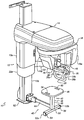
도 1은 구강외 이미징 장치(10)의 실시형태를 예시한다. 장치(10)는 지지 칼럼일 수 있는 지지 프레임(12)을 포함하는 지지 구조체를 포함한다. 칼럼(12)은 2차원 또는 3차원으로 조정될 수 있다. 예를 들어, 칼럼(12)은 신축형일 수 있고, 고정된 하부 부분(12b) 위로 슬라이드 가능하게 장착된 상부 부분(12a)을 포함할 수 있다.1 illustrates an embodiment of an extraoral imaging device 10. Device 10 includes a support structure that includes a
지지 구조체는 또한, 수직 칼럼(12)에 의해 지지 또는 유지될 수 있는 수평 장착부(14)를 포함한다. 수평 장착부(14)는 수직 칼럼(12)으로부터 멀리 연장되며 실질적으로 수직 칼럼에 수직일 수 있다. 수평 장착부(14)는 수직 칼럼(12)에 대하여 이동할 수 있다. 보다 구체적으로, 수평 장착부(14)는 수직 상부 부분(12a)에 고정식으로 장착되며, 그에 따라 수직 상부와 함께 이동 가능하다. 예를 들어, 수직 칼럼의 뒤에 놓이는 액추에이터, 예컨대, 전기 타입의 액추에이터(도면에는 나타나 있지 않음)는 제어된 방식의 수직 움직임으로 수평 장착부(14)를 구동하도록 명령을 받을 수 있다. 수평 장착부(14)는 갠트리(16)를 지지할 수 있다. 갠트리(16)는 지지 구조체에 대하여, 특히 수평 장착부(14)에 대하여 이동 가능하다. 갠트리(16)는 특히 수평 장착부(14)에 대하여 회전 가능할 수 있다. 갠트리(16)는, 선택된 이미징 프로세스에 따라, 이미징 프로세스의 동작 동안 정지해 있을 수 있거나 또는 소정의 여러 궤적 중 하나를 추종할 수 있는 수직 회전축을 중심으로 회전 가능할 수 있다. 갠트리(16)를 주어진 움직임으로 구동시키기 위한 기지의 구동 메커니즘(도시되지 않음)이 수평 장착부(14) 내부에 통합된다. 실시예로서, 이러한 구동 메커니즘은 X, Y 평면에서 제1 움직임을 부여하기 위한 모터, 예컨대, 2개의 스텝식 모터(step by step motor), 및 수직축(Z)을 중심으로 회전 움직임을 부여하기 위한 모터, 예컨대, 브러시리스 모터(brushless motor)를 포함한다.The support structure also includes a
갠트리(16)는 x-레이 소스(18) 및 x-레이 소스에 대응하여 배치된 적어도 하나의 x-레이 센서(20)를 모두 지지한다. x-레이 소스(18) 및 적어도 하나의 x-레이 센서(20)는 서로 마주보도록 배치될 수 있다. 갠트리(16)는 2개의 대향하여 하향 연장되는 아암을 포함할 수 있으며, 제1 아암(16a)은 그것에 부착된 x-레이 소스(18)를 지지하고, 대향하는 제2 아암(16b)은 그것에 부착된 적어도 하나의 x-레이 센서(20)를 지지한다.
x-레이 소스(18)는, 작동시에, 적어도 하나의 x-레이 센서(20)에 충돌하기 전에, 이미징 영역, 예컨대, 환자의 머리의 위치결정을 위한 작업 영역의 전부 또는 일부에 방사되는 x-레이 빔을 방출한다.The
본 실시형태에 있어서, 적어도 하나의 x-레이 센서(20)는 파노라마 센서, 예컨대, 슬릿형 센서, 체적측정 또는 컴퓨터화된 센서(예컨대, 직사각형, 정사각형) 또는 두부 계측 센서 또는 여러 센서를 포함할 수 있다.In this embodiment, the at least one x-ray sensor 20 may comprise a panoramic sensor, such as a slit sensor, a volumetric or computerized sensor (eg, rectangular, square) or head measurement sensor or several sensors. Can be.
장치에 있는 센서 또는 센서들에 따라, 파노라마, 체적측정 또는 컴퓨터화된 단층 촬영, 및 두부 계측 모드 중에서 하나의 또는 여러 작동 모드 또는 이미징 프로세스(1, 2 또는 3)를 사용할 수 있다.Depending on the sensor or sensors in the device, one or several modes of operation or
지지 구조체는 또한 지지 프레임, 보다 구체적으로는 수직 칼럼(12)에 연결된 환자 위치설정 아암(22)을 포함할 수 있다. 환자 위치설정 아암(22)은 지지 프레임에 대하여 이동 가능하다. 특히, 아암(22)은 명령에 따라 상하로 움직일 수 있도록 수직 칼럼(12)을 따라 슬라이드될 수 있다. 환자 위치설정 아암(22)은 고정된 하부 부분 수직 칼럼(12b)에 대하여 슬라이드 가능하게 장착된 아암 지지부(22a)로부터 연장된다. 환자 위치설정 아암(22)은 수평 장착부(14)의 연장 방향과 실질적으로 대응하는 방향으로 장치를 따라 연장된다. 환자 위치설정 아암(22)은 수평 장착부(14)와 실질적으로 평행한 관계로 장치에 대하여 측방향으로 배치된다. 예를 들어, 수직 칼럼의 뒤에 놓이는 액추에이터, 예컨대, 전기 타입의 액추에이터(도면에는 나타나 있지 않음)는 제어된 방식의 수직 움직임으로 아암 지지부(22a)를 구동하도록 명령을 받을 수 있다.The support structure may also include a support frame, more specifically
환자 위치설정 아암(22)은 환자를 장치 내에서 정해진 위치에 위치시키는 역할을 한다. 일 실시형태에서, 환자 위치설정 아암(22)은 장치(10)의 동작 모드의 선택에 따라 환자를 이미징 영역에 위치시킬 수 있다.The
환자 위치설정 아암(22)은 일반적으로 아암의 자유 단부(22b) 또는 그 근방에 위치되는 하나 이상의 환자 위치설정 및/또는 유지 시스템을 포함할 수 있다.
하나 이상의 환자 위치설정 및/또는 유지 시스템은 환자의 머리의 해부학적 구조를 상이한 방향들을 따라 위치시키고 임의의 가능한 움직임을 감소시키기 위해 검사 중에 환자의 머리를 움직이지 못하게 한다.One or more patient positioning and / or maintenance systems prevent the patient's head from moving during the examination to position the anatomical structure of the patient's head along different directions and reduce any possible movement.
수행할 검사 유형마다 하나의 또는 여러 시스템이 존재한다. 아암(22)은 이들 시스템을 수용하도록 구성된다.There is one or several systems for each type of test to be performed.
도 1에 예시된 바와 같이, 24로 표시된 이들 시스템 중 하나는 아암(22)에 분리 가능하게 부착되며 그로부터 상향으로 연장되는 2개의 일시적 유지 부재를 포함한다. 하나의 일시적 유지 부재 만이 나타나 있지만, 다른 하나는 아암(16b)에 의해 가려져 있다.As illustrated in FIG. 1, one of these systems, denoted 24, includes two temporary retaining members detachably attached to and extending upward from the
다른 예시된 시스템은 아암(22)에 분리 가능하게 부착되며 그로부터 상향으로 연장되는 턱(chin) 지지부(26)이다. 턱 지지부(26)는 2개의 일시적 유지 부재 사이에 위치될 수 있다.Another illustrated system is a
그 밖의 가능한 부착식, 이동식 또는 일체형 시스템, 즉 코 지지부(nasal support), 물기 지지부(bite support) 등이 고려될 수 있다.Other possible attachable, mobile or integrated systems may be contemplated, such as nasal support, bite support, and the like.
핸들 조립체(28)는 아암의 자유 단부(22b)에, 아암의 아래에, 그리고 아암과 평행한 관계로 위치될 수 있다. 이 핸들 조립체(28)는 이미징 프로세스 도중에 정지 상태를 유지하도록 환자에 의해 파지될 수 있는 2개의 수직한 개별 핸들부(28a, 28b)를 포함한다.The
전체적으로 이 핸들 조립체(28)는 수평 베이스부(28c) 및 아암(22)에 고정된 2개의 수직 상향 연장 브랜치(28a, 28b)를 포함할 수 있는 U 형상을 갖는다. 각 브랜치는 수직 핸들부의 역할을 한다.The
환자 위치설정 아암(22)은 또한 장치의 사용자가 장치의 특정 기능을 보면서 구동할 수 있게 하는 모니터 또는 디스플레이 조립체(30)를 지지한다.The
장치(10)는 지지 프레임(12)에 연결된 좌석 배치구조체(40)를 더 포함한다. 좌석 배치구조체(40)는 다음과 같은 적어도 2개의 별개의 위치들 사이에서 이동 가능하다:The device 10 further includes a
― 좌석 배치구조체(40)가 갠트리(16) 및 수평 장착부(14)와 미리 정해진 공간 관계(도 1, 예컨대 밑 또는 아래)를 갖는 작업 영역에 위치되는 작업 위치,A work position in which the
― 갠트리(16) 아래의 작업 영역을 비워두도록 좌석 배치구조체(40)가 작업 영역으로부터 멀리 위치되는 적어도 하나의 휴지 위치.At least one rest position in which the
도 2 및 도 3은 좌석 배치구조체(40)에 대한 2개의 예시적인 상이한 가능한 휴지 위치를 예시한다(장치의 나머지는 간결성 때문에 표현되지 않음): 즉, 좌석 배치구조체는 바람직하게는 하나가 다른 하나로부터 180°로 배치된 직경 방향으로 대향된 2개의 휴지 위치를 차지한다. 그러나, 다른 실시형태들은 180°보다 큰 또는 180°보다 작은(예컨대, 최대 270°까지의 또는 90° 미만의) 휴지 위치들 사이의 각도를 고려할 수 있다. 도 1의 작업 위치는 2개의 극단으로 대칭되는 휴지 위치들에 대한 중앙 위치일 수 있다. 대안으로서, 작업 위치와 원하는 휴지 위치 사이의 각도가 최대 180°가 될 수 있다. 또한, 도 1의 작업 위치는 하나의 또는 2개의 극단으로 대칭되는 휴지 위치에 더 가까운 오프셋 위치일 수 있다. 도 1에서, 좌석 배치구조체(40)는 갠트리(16) 및 수평 장착부(14)의 아래에서 그와 평행한 관계로 놓인다. 2개의 휴지 위치 각각에서는, 좌석 배치구조체(40)가 더 이상 갠트리(16) 및 수평 장착부(14)의 아래에 있지 않고, 예를 들어 수평 장착부(14)에 대하여 90°의 각도를 이룬다.2 and 3 illustrate two exemplary different possible rest positions for the seat arrangement 40 (the rest of the device is not represented because of simplicity): that is, the seat arrangement is preferably one another Occupies two diametrically opposed rest positions in the radial direction disposed at 180 ° from. However, other embodiments may consider the angle between rest positions greater than 180 ° or less than 180 ° (eg, up to 270 ° or less than 90 °). The working position of FIG. 1 may be a central position with respect to two extremely symmetrical rest positions. As an alternative, the angle between the working position and the desired resting position can be up to 180 °. Also, the working position of FIG. 1 can be an offset position closer to one or two extreme symmetrically rested positions. In FIG. 1, the
특정한 예시적인 방법 및/또는 장치 실시형태들은 좌석 배치구조체(40)를 앞서 설명한 다양한 상이한 위치들 사이에서 반복적으로 왕복하여 이동시킬 수 있다. 예를 들어, 일 실시형태에서, 좌석 배치구조체(40)는 피봇식 조립체를 통해 지지 프레임(12)에 대하여 피봇하여 앞서 설명한 상이한 위치들 사이에서 좌석 배치구조체의 회전을 가능하게 하도록 구성된다.Certain example method and / or device embodiments may move
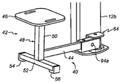
도 1 내지 도 3에 도시된 바와 같이, 좌석 배치구조체(40)는 좌석 조립체(42) 및 연결 아암(44)을 포함할 수 있다. 좌석 조립체(42)는 좌석부(46) 및 지면 지지를 위한 다리 조립체(48)를 포함할 수 있다. 다리 조립체(48)는 수직 중앙 지지 부재(50) 및 지지 부재(50)를 지탱하는 바아(bar)일 수 있는 수평 횡단 부재(52)를 포함할 수 있다. 횡단 부재(52)는 횡단 부재의 아래쪽 및 그 대향하는 측면 단부들에 위치하는 패드(54, 56)가 2개의 그 대향 단부(52a, 52b)에 제공된다. 패드(54 및 56)는 횡단 부재가 지면 위로 들어 올려진 상태를 유지할 수 있게 한다.As shown in FIGS. 1-3, the
좌석 조립체(42)는 그 두께를 통해 형성되고 그 외주연부에 근접하여 위치되는 슬롯(58, 60), 예컨대 세장형 슬롯을 포함할 수 있다. 슬롯(58, 60)은 좌석 조립체(40)를 수동으로 취급하여 도 1의 중간 작업 위치로부터 도 2 및 도 3의 2개의 극단적인 휴지 위치 중 한 위치를 향해 및 그 반대로 이동시키는 조작부의 역할을 한다. 슬롯(58, 60)은 좌석 조립체를 더 쉽고 편리하게 조작하기 위해 좌석 조립체의 대향하는 양측에 배치될 수 있다.The
특히, 칼럼(12)은 베이스플레이트 또는 지지 플레이트(62)에 의해 그 하단부가 지지되고 좌석 배치구조체(40)는 앞서 설명한 피봇식 조립체를 통해 베이스플레이트(62)에 연결된다. 고정된 하부 부분(12b)은 베이스플레이트(62)에 결합된다.In particular, the
좌석 배치구조체(40)와 지지 프레임(12)의 연결은 좌석 배치구조체의 종단면에서의 연결 구역의 확대도인 도 4에서 보다 구체적으로 설명된다.The connection of the
장착 브래킷(64)은 종래의 영구적인, 고정된 또는 재부착 가능한 체결 부재, 예컨대 나사를 통해 베이스플레이트(62)에 고정되며, 여기서는 명확성을 위해 도시되지 않는다.The mounting
장착 브래킷(64)은, 예를 들어 개구(O)가 칼럼(12)에 대향하여 배향된 C 형상을 갖는다. 장착 브래킷(64)은 3개의 부분, 즉 그 뒤쪽이 칼럼(12)에 수직하게 배향된 중간 부분(64a), 수평하게 배향되고 베이스플레이트(62)에 대하여 고정되게 놓이는 하부 부분(64b) 및 하부 부분(64b)에 대향하는 상부 수평 부분(64c)을 포함한다. 하부 부분(64b)과 상부 부분(64c)은 모두 중간 부분에 인접하여 함께 개구(O)를 규정한다.The mounting
상기 피봇식 조립체는 상부 부분(64c)과 하부 부분(64b) 사이에 수직으로 배치된 피봇식 중공축(66)을 통해 좌석 배치구조체(40)의 하나의 자유 단부(40a)에서 장착 브래킷(64)과 연결되어 장착된다. 중공축(66)은 상부 및 하부 부분(64c, 64b)에 각각의 체결 부재(68, 70), 예컨대 나사를 통해 체결된다. 체결 부재(68, 70)는 제각기 상부 및 하부 부분(64c, 64b) 각각의 외부면을 통해 축(66)의 2개의 나사형 중공 단부에 결합된다.The pivoted assembly is mounted at one
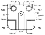
특히, 인덱싱된 지지부 또는 패드(72)는 좌석 배치구조체 단부(40a)와 하부 부분(64b)의 상부면 사이에 삽입되어 하부 부분에 고정된다. 인덱싱된 패드(72)는 도 4의 좌석 배치구조체 단부(40a)와 접촉하는 인덱싱된 상부면(72a)을 포함하며, 도 5에서 위쪽으로부터 표시된 3개의 별개의 인덱싱된 위치를 포함하도록 구성된다. 인덱싱된 상부면(72a)은 해당 상부면의 4개의 모서리 중 하나에 각각 위치되는 4개의 융기부, 즉 제1 공간(S1)을 사이에 규정하는 2개의 개별 융기부(74b 및 74c)와 감소된 제2 공간(S2)을 사이에 규정하는 보다 큰 치수의 2개의 다른 개별 융기부(74d 및 74e)를 포함하도록 구성된다. 융기부(74b) 및 보다 큰 융기부(74d)는 바람직하게는 감소된 제2 공간(S2)과 동일한 폭의 공간(S3)을 그 사이에 규정한다. 융기부(74c) 및 보다 큰 융기부(74e)는 바람직하게는 감소된 제2 공간(S2)과 동일한 폭의 공간(S4)을 그 사이에 규정한다.In particular, the indexed support or
대응하는 융기부들 사이의 공간(S2, S3 및 S4)은 각각이 작업 위치 및 2개의 휴지 위치 중 하나에 위치맞춤되는 3개의 인덱싱된 위치 중 하나에서 좌석 배치구조체 단부(40a)를 각각 수용할 수 있게 한다. 작업 위치에서, 좌석 배치구조체 단부(40a)는 공간(S2)을 점유하고(보다 구체적으로는, 단부(40a)의 하부면의 일부가 면(72a)에 대하여 공간(S2)에 놓임), 보다 작은 융기부들(74b, 74c) 사이에 배치되는 곳까지 연장된다.The spaces S2, S3 and S4 between the corresponding ridges can each accommodate the
보다 작은 융기부들(74b, 74c)은 그 사이에 관통 구멍(76, 78)의 위치설정을 가능하게 하는 한편, 구멍들(76, 78) 사이의 작업 인덱싱된 위치에 좌석 배치구조체 단부(40a)를 수용하기에 충분한 공간을 남긴다. 이들 구멍은 인덱싱된 패드(72)를 하부 부분(64b)에 체결하기 위한 체결 부재(간결성을 위해 표현되지 않음)를 수용할 수 있게 한다.The
도 6은 작업 인덱싱된 위치로부터 도 5의 공간(S3)에 의해 규정되는 휴지 인덱싱된 위치로 이동된 좌석 배치구조체 단부(40a)의 횡단면에서의 확대도이다.6 is an enlarged view in cross section of the
도 6은 각각의 융기부(74b, 74d)의 경사진 에지(74b1, 74d1)를 예시하며, 단부(40a)는 이들 경사진 에지 사이에 위치된다.6 illustrates the sloped edges 74b1, 74d1 of each
대응하는 공간(S2)과 공간(S4)의 양측에 위치되는 경사진 에지(74d2, 74e2, 74e1, 74c1)를 갖는 다른 융기부들에 대해서도 유사한 배치구조가 제공된다. 경사진 에지들의 각 쌍은 단부(40a)가 위치될 수 있는 홈을 대응하는 중앙 공간과 함께 규정한다.Similar arrangements are provided for other ridges with corresponding spaces S2 and inclined edges 74d2, 74e2, 74e1, 74c1 located on either side of space S4. Each pair of inclined edges defines a groove along which
전체 경사진 에지들은 하나의 인덱싱된 위치로부터 다른 인접한 인덱싱된 위치로의 단부(40a)의 운동(예컨대, 회전)을 용이하게 만든다. 경사진 에지들은 단부(40a)가 홈을 벗어나도록 안내하고 돕는 경사부(ramp)로서 작용한다. 다른 공지된 종래의 에지들, 측부들 또는 이행부들이 사용되어, 하나의 인덱싱된 위치로부터 다른 인접한 인덱싱된 위치로의 단부(40a)의 운동을 보다 용이하게 만들 수 있다.The entire beveled edges facilitate the movement (eg, rotation) of the
도 4 및 도 6에 예시된 바와 같이, 좌석 배치구조체(40)는 인덱싱된 패드(72)에 대하여 적어도 하나의 탄성 부재(80)를 통해 가압된다. 탄성 부재(80)는 단부(40a)와 상부 부분(64c) 사이에서 연장되는 축(66)의 돌출 단부(66a) 주위에 배치된다. 탄성 부재(80)는 단부(40a)를 대응하는 인덱싱된 위치(도 4의 작업 위치 및 도 6의 휴지 위치)에 대하여 하향으로 편향시키는 압축된 상태로 이 위치에 유지된다. 따라서, 좌석 배치구조체는 탄성 부재(80)로 인해 3개의 인덱싱된 위치 중 하나에서 강제적으로 유지된다. 비제한적인 실시예로서, 탄성 부재(80)는 스프링일 수 있거나 또는 몇 개의 스프링으로 구성된 배치구조체일 수 있다.As illustrated in FIGS. 4 and 6, the
상기 좌석 배치구조체 및 그 이동 메커니즘은 편리하고 신뢰성 있는 배치구조를 장치에 제공한다. 이 새로운 배치구조 덕분에 이미징 프로세스는 환자에 대하여 재현 가능하거나 최적화된 상태로 작동될 것이고, 즉 고령의 환자와 어린 환자는 프로세스 동안 갠트리 아래에 앉을 것이다. 이는 갠트리 아래에 서 있을 때 어려움을 겪을 수 있는 키가 큰 사람에게도 유용하다.The seat arrangement and its movement mechanism provide the device with a convenient and reliable arrangement. Thanks to this new configuration, the imaging process will operate reproducibly or optimized for the patient, ie older patients and younger patients will sit under the gantry during the process. This is also useful for tall people who may have difficulty standing under the gantry.
이미징 프로세스가 종료되면, 좌석 배치구조체는 작업 위치가 방해받지 않도록 쉽고 빠르게 휴지 위치로 이동될 수 있다.At the end of the imaging process, the seating arrangement can be easily and quickly moved to the rest position so that the working position is not obstructed.
좌석 배치구조체(40)의 피봇식 조립체와 관련하여 앞서 설명된 것은 모두 그 자유 단부에 임의의 특정한 구성을 갖지 않는 좌석 배치구조체에도 마찬가지로 적용된다. 이러한 좌석 배치구조체는 연결 아암만을 가지며, 이 연결 아암의 단부는 축(66)을 중심으로 피봇 가능하게 장착되도록 배치된다.What has been described above in connection with the pivotal assembly of the
좌석 배치구조체(40)의 보다 상세한 예시적인 가능한 실시형태가 이제 설명될 것이다. 이 실시형태는 도 1 내지 도 4에 예시된 좌석 배치구조체 단부(40a)의 특정한 구성을 예시한다.A more detailed exemplary possible embodiment of the
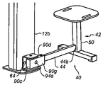
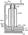
이와 관련하여, 좌석 배치구조체(40)는 연결 아암(44)을 지지 프레임에 연결하는 연결 부재(90)를 포함한다. 이 실시형태에서, 연결 아암(44)은 지지 프레임에 직접 연결되지 않고 연결 부재(90)가 연결 아암(44)을 길이방향으로 연장시킨다. 이 실시형태에서, 연결 부재(90)는, 예컨대 세장형의 중공 형상을 가지며, 다음과 같은 2개의 대향 단부를 갖는다:In this regard, the
― 아암(44)의 제1 단부(44a)에 연결되도록 구성된 제1 단부(90a);A
― 연결 부재(90) 및, 그에 따른 전체 좌석 배치구조체(40)를 하나의 인덱싱된 위치로부터 다른 인덱싱된 위치로 이동시키기 위해, 앞서 설명한 피봇식 조립체를 통해 인덱싱된 면(72a)에 대하여 피봇 가능하게 장착되도록 구성된 제2 단부(90b).Pivotable with respect to the indexed
연결 아암(44)의 제2 대향 단부(44b)는 좌석 조립체(42)(도 3)의 지지 부재(50)에 연결된다.The second
제1 단부(90a)는 길이방향 중공 연결 부재(90) 내부에 아암(44)의 제1 단부(44a)의 삽입을 가능하게 하도록 구성되며 제거 가능하게 삽입되는 플러그(92)에 의해 일시적으로 폐쇄된다. 플러그(92)는 제1 단부(44a)에 의해 횡단되도록 천공된다.The
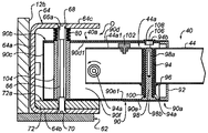
본 실시형태에서, 연결 부재(90)는 도 3 및 도 4에서 함께 예시된 5개의 벽(90c-g), 즉 단부(90b)를 폐쇄하는 단부 수직벽(90c), 2개의 대향하는 상부 및 하부벽(90d, 90e) 및 2개의 대향하는 측벽(90f, 90g)을 포함하는 중공 케이싱의 형태이다. 벽들(90d-g)은 플러그(92) 및 횡단 아암(44)에 의해 폐쇄되는 개방 단부(90a)를 함께 형성한다.In this embodiment, the connecting
제1 단부(44a)는 제1 단부(44a)가 피봇 가능하게 장착되는 수평 피봇 축(94a)을 통해 연결 부재(90)에 연결된다. 피봇 축(94a)은 벽(90f, 90g) 및 단부(44a)에 제공되는 천공부를 통해 그 천공부와 위치맞춤되어 삽입된다.The
또한, 제1 단부(44a), 또는 제1 단부(44a)에 인접한 아암의 종단부는 하부 벽(90e)의 내부면(90e1)에 탄성적으로 장착된다. 제1 단부(44a)는, 아암(44)의 길이방향 축에 대하여 횡방향으로 배치되며 그 대향하는 2개의 하부 및 상부 단부(94a, 94b)에서 개방되는 공동(94)을 포함하도록 구성된다. 공동(94)은, 아암(44)의 전체 높이에 걸쳐 연장되며 단부(44a)의 하부면으로부터 하향으로 돌출되는 횡단 벽(96)에 의해 규정된다. 수직하게 배향된 로드(98)는 내부 하부면(90e1)에 놓이고 그것에 결합될 수 있다. 로드(98)는 로드 주위에 배치되는 적어도 하나의 탄성 부재(100)에 대한 지지축으로서의 역할을 한다. 적어도 하나의 탄성 부재(100)와 로드(98)는 모두 공동(94) 내부에 수용되고 적어도 하나의 탄성 부재(100)는 압축된 상태에 있으며, 그에 따라 제1 단부(44a)가 상향으로 가압된다. 적어도 하나의 탄성 부재(100)는, 예컨대 스프링을 포함할 수 있다.Also, the
엘라스토머 패드(102)는 제1 단부(44a)의 상부 부분(44a1)의 외부면에 배치되어, 연결 아암(44)이 특정 조건 하에서 상향으로 가압될 때 상부면(90d)의 내부면(90d1)에 대한 기계적 정지부로서의 역할을 한다.The
연결 부재(90)의 제2 단부(90b)는 각각의 상부 및 하부 벽(90d, 90e)에 제공된 2개의 상부 및 하부 구멍 사이에 배치된 수직으로 연장되는 시스(sheath)(104)를 포함한다. 시스(104)는 벽(90d 및 90e)에 고정되고 축(66)을 둘러싸고 있다.The
구멍(94b)은 연결 부재(90) 내부에 아암 단부(44a)를 장착하는 데 사용된다는 점에 유의한다. 장착 작업은 공동(94) 내부의 탄성 부재(100) 및 탄성 부재에 의해 둘러싸인 로드(98)의 삽입으로 시작된다. 이어서, 나사(도시되지 않음)가 로드(98)의 내부 나사형 단부(98a) 내로 구멍(94b)을 통해 삽입된다. 이 일시적인 배치구조는, 탄성 부재(100)와 로드(98)를 아암(44)과 함께 묶어서 부분적으로 중공 연결 부재(90)의 내부에 아암(44)을 길이방향으로 도입할 수 있게 한다. 아암은 벽(90f 및 90g)에 있는 천공부들이 단부(44a)에 있는 천공부들과 위치맞춤되고 상부 벽(90d)에 제공된 구멍(106)이 구멍(94b)과 위치맞춤되는 길이방향 위치로 도입된다. 이 위치에서, 로드(98)의 헤드(98b)가 내부면(90e1)에 대하여 놓인다. 축(94a)은 대응하는 천공부를 통해 수평으로 삽입되고 거기에 고정식으로 장착되어서, 아암(44)을 피봇 가능한 장착을 통해 연결 부재(90)에 연결한다. 또한, 나사형 단부(98a) 또는 로드(98)에 고정되는 나사는 관통 구멍(106)의 위로부터 풀린다. 이어서, 탄성 부재(100)가 공동(94) 내부에서 부분적으로 연장되어 단부(44a)를 상향으로 가압할 수 있다. 다음으로, 플러그(108)가 구멍(106) 내로 도입되어 구멍을 밀봉한다.Note that the
도 4에 예시된 좌석 배치구조체(40)의 위치는 환자가 도 1의 좌석부(46) 상에 있는 상황에 대응한다.The position of the
이 위치에서, 좌석 조립체를 통해 연결 아암(44)에 가해지는 환자의 체중은 탄성 부재(100)를 그 하우징(94) 내부에서 완전히 압축된 상태로 유지시킨다. 좌석 조립체는 패드(54, 56)(도 1)를 통해 지면에 놓여 있다. 따라서, 아암(44)은 하부 및 수평 위치에 있고 패드(102)는 상부면(90d)의 내부면(90d1)으로부터 떨어져 있다. 이 위치에서, 연결 부재(90)는 환자의 체중으로 인하여 작업 인덱싱된 위치에서 인덱싱된 면(72a)에 대하여 더 유지된다. 좌석부 상에 환자가 없을 때, 탄성 부재(80)는 작업 인덱싱된 위치 또는 임의의 다른 휴지 인덱싱된 위치에서 인덱싱된 면(72a)에 대하여 연결 부재(90)를 하향으로 가압하기에 충분한 크기로 된다는 점에 유의해야 한다.In this position, the patient's weight applied to the connecting
환자가 일어서면(환자가 받은 검사가 끝났을 때), 환자의 체중은 탄성 부재(100)에 의해 가해지는 상향의 힘을 더 이상 보상하지 않는다. 이어서, 탄성 부재는 연결 아암(44)을 상향으로 편향시킨다. 단부(44a)가 피봇 축(94a)을 중심으로 피봇 가능하게 장착됨에 따라, 아암(44)의 상향 움직임은 축(94a)을 중심으로 그 피봇 운동을 야기하고 패드(102)는 내부면(90d1)에 맞닿는다. 탄성 부재(100)에 의해 가해지는 힘은 연결 부재(90)를 상승시킬 만큼 충분히 크지는 않다.Once the patient is up (at the end of the patient's examination), the patient's weight no longer compensates for the upward force exerted by the
연결 아암(44)의 이 상부 위치는 좌석 조립체 상에 환자가 없는 경우의 아암에 대한 휴지 위치에 대응한다. 이러한 위치는 도 7에 예시되며, 여기서는 좌석 배치구조체(40)가 여전히 작업 인덱싱된 위치에 있다. 도시된 바와 같이, 아암(44)은 축(94a)을 중심으로 상향으로 피봇해 있으며, 이는 좌석 조립체(42)를 지면에 대하여 상승시키고 있다. 따라서, 패드(54, 56)는 더 이상 지면과 접촉하지 않는다. 도 7에 도시된 바와 같이, 아암(44)과 연결 부재 또는 케이싱(90)은 더 이상 서로 평행하지 않다. 좌석 조립체(42)의 이러한 상승된 위치는 장치의 사용자가 좌석 배치구조체를 거의 수직방향으로 수동으로 회전시키는 것을 용이하게 한다. 패드가 여전히 지면에 놓여 있으면, 사용자는 좌석 배치구조체를 회전시키기 전에 먼저 들어올려야 한다. 상승된 위치에서는, 사용자가 좌석 배치구조체를 도 2 및 도 3의 2개의 휴지 인덱싱된 위치 중 하나를 향한 회전 운동으로 단순히 구동하여 좌석 배치구조체(40)를 도 1의 작업 위치로부터 떨어진 위치로 치워둘 수 있다. 회전 운동은, 연결 부재(90)가 앞서 설명한 바와 같이 위치된 홈을 벗어나는 것을 돕는 인덱싱된 면(72a)의 경사진 에지 덕분에 용이해진다. 도 2 및 도 3은, 아암(44)의 위치가 도 7에 대하여 앞서 설명한 휴지 위치에 있는 상태로, 2개의 휴지 인덱싱된 위치의 각각에 있는 좌석 배치구조체(40)를 예시한다. 이들 휴지 위치 각각에서는, 좌석 배치구조체(40)가 브래킷(64)에 맞닿아서 어떠한 추가적인 회전 운동도 방지된다.This upper position of the connecting
도 8 내지 도 13b에 예시된 다른 실시형태들은 구강외 치과용 이미징 장치에 통합된 다른 가능한 피봇식 좌석 배치구조체를 도시한다. 장치는, 도 1의 장치(10)일 수 있거나, 또는 적어도: x-레이 소스 및 x-레이 소스에 대응하는 적어도 하나의 x-레이 센서를 지지하는 지지 프레임 및 갠트리― 갠트리는 지지 프레임에 대하여 이동 가능함 ―를 포함하는 것과 유사한 장치일 수 있다. 이하의 실시형태에서는, 장치에 대해서 이 이상 설명하지 않는다.Other embodiments illustrated in FIGS. 8-13B show another possible pivotal seating arrangement integrated into an extraoral dental imaging device. The apparatus may be the apparatus 10 of FIG. 1, or at least: an x-ray source and a support frame for supporting the at least one x-ray sensor corresponding to the x-ray source and the gantry-gantry with respect to the support frame. May be a device similar to the one comprising:-moveable. In the following embodiment, the apparatus is not described above.
좌석 배치구조체를 통합하는 장치가 이하의 실시형태들의 도면들에서 항상 표현되는 것은 아니지만, 이는 설명된 실시형태들의 암시적인 부분인 것으로 이해되어야 한다. 이하의 실시형태들에서, 각각의 좌석 배치구조체는 지지 프레임에 연결되고, 적어도 2개의 별개의 위치, 즉 작업 위치 및 적어도 하나의 휴지 위치, 예컨대 도 1 내지 도 7을 참조하여 앞서 설명한 바와 같은 2개의 휴지 위치 사이에서 이동 가능하다.Although the device incorporating the seating arrangement is not always represented in the figures of the following embodiments, it should be understood that this is an implicit part of the described embodiments. In the following embodiments, each seat arrangement is connected to a support frame and has at least two separate positions, namely a working position and at least one resting position, for example two as described above with reference to FIGS. 1 to 7. Movable between two resting positions.
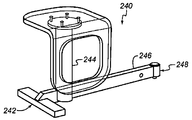
도 8은 지지 프레임에 대하여 피봇 가능하게 장착된 좌석 배치구조체(202)를 포함하는 장치(200)를 나타낸다. 위에서 피봇식 조립체에 대하여 설명된 것은 모두 여기에 적용될 수 있으며 설명을 반복하지 않는다.8 shows an
좌석 배치구조체(202)는 피봇식 조립체(204)를 통해 피봇 가능하게 장착되고, 좌석 조립체(206) 뿐만 아니라 연결 아암(208)을 포함한다. 좌석 조립체(206)는 좌석부(210) 및 지면 지지를 위한 다리 조립체(212)를 포함한다. 다리 조립체(212)는, 예컨대 원형의 수직 중앙 부재(214) 및 베이스플레이트(216)를 더 포함한다. 좌석 배치구조체(202)는 작업 중앙 위치로부터 90° 피봇 운동이 이루어진 후의 피봇된 위치에서 202'로서도 표시된다.The
도 9는 피봇식 조립체(224)를 통해 지지 프레임에 대하여 피봇 가능하게 장착된 좌석 배치구조체(222)를 갖는 장치(220)를 나타낸다. 좌석 배치구조체(222)는 좌석 조립체(226)뿐만 아니라 연결 아암(228)을 포함한다. 좌석 조립체(226)는 좌석부(230) 및 지면 지지를 위한 다리 조립체(232)를 포함한다. 다리 조립체(232)는 수직 중앙 부재(234) 및 베이스플레이트(236)를 더 포함한다. 베이스플레이트(236)는, 그 2개의 대향 단부들 중 하나가 수직 중앙 부재(234)에 각각 결합된 2개의 세장형 부분(236a, 236b)을 포함한다. 2개의 부분(236a, 236b)은 실질적으로 V 형상을 형성하도록 서로로부터 멀리 외향으로 연장된다. 이렇게 구성된 베이스플레이트(236)는 도 8의 베이스플레이트(216)보다 더 안정적인 지면 지지를 제공한다. 좌석부(230)는 도 8에서와 같은 원형이 아니라, 실질적으로 정사각형이다. 좌석부(230)는 또한, 좌석을 형성하는 수평 부분(230a) 이외에, 환자의 다리에 대한 지지부로서의 역할을 하는 수직 하향 연장 부분(230b)을 포함한다. 부분(230b)은 좌석부(230)를 더 가볍게 만들기 위해 그 중간 부분에서 오목하게 되어 있거나 또는 부분적으로 제거되어 있다.9 shows an
도 10은 좌석 배치구조체(240)만이 예시되어 있는 도 9에 대한 변형 실시형태를 예시한다. 이 배치구조체는 좌석 배치구조체(222)와는 주로 이하의 점에서 상이하다:FIG. 10 illustrates a variant embodiment of FIG. 9 where only the
― 지면 지지를 위한 베이스플레이트(242)는 실질적으로 도 1의 횡단 부재(52)와 같은 직선 형상을 갖고;The
― 수직 중앙 부재(244)는 베이스플레이트(242)로부터 멀어지도록 피봇식 조립체(248)를 향해 아암(246)을 따라 축방향으로 이동된다.The vertical
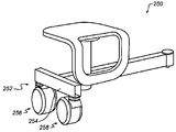
도 11은 좌석 배치구조체(250)만이 예시되어 있는 도 10에 대한 변형 실시형태를 예시한다. 이 배치구조체는 주로 지면 지지를 위한 베이스플레이트(252)가, 예컨대 2개의 캐스터(256, 258) 상에 장착되는 횡단 부재(254)라는 점에서 좌석 배치구조체(240)와 상이하다. 캐스터는 하향으로 배향되는 레일 형태를 취할 수 있는 부재(254)와 정렬하여 배치된다. 캐스터는 레일 내부에 있는 장착 지지 부재(도시되지 않음)를 통해 장착된다. 이 배치구조는 좌석 배치구조체를 수동으로 피봇시키는 데 추가적인 도움을 제공한다.FIG. 11 illustrates a variant embodiment of FIG. 10 where only the
도 12는 단지 좌석 배치구조체(260)가 전개된 또는 펼쳐진 위치에 예시되어 있고, 수축된 또는 절첩된 위치에서는 260'으로 지칭되는 추가적인 실시형태를 예시한다. 좌석 배치구조체(260)는 도 8의 좌석 배치구조체(202)의 구성요소들 중 일부, 즉 좌석부(210), 수직 부재(214) 및 베이스플레이트(216)를 갖는 좌석 조립체(206)를 그대로 채용한다. 그러나, 좌석 배치구조체(260)는 힌지식 아암인 연결 아암(262)을 포함한다. 힌지식 아암(262)은 제1 힌지 메커니즘(268)에 의해 함께 연결된 2개의 세장형 부분(264, 266)을 포함한다. 세장형 부분(264)은 단지 270으로 표시되어 있는 부재인 지지 프레임에 연결된다. 이 부재는 도 1의 베이스플레이트(62)에 부착될 수 있다. 세장형 부분(266)은 좌석 조립체(206)의 수직 부재(214)에 연결된다.12 merely illustrates a further embodiment where
세장형 부분(264, 266)과 지지 프레임(270) 및 좌석 조립체(206)와의 사이의 연결부들은 제각기 제2 힌지 메커니즘(272) 및 제3 힌지 메커니즘(274)을 포함한다.The connections between the
상기 3개의 힌지 메커니즘 각각은 동일할 수 있고, 도 4와 동일한 유형의 피봇식 조립체를 포함할 수 있다. 도 4의 피봇식 조립체와는 달리, 각 힌지 메커니즘의 피봇 축은 수평이다.Each of the three hinge mechanisms may be identical and may include a pivotal assembly of the same type as in FIG. 4. Unlike the pivoted assembly of FIG. 4, the pivot axis of each hinge mechanism is horizontal.
신장된 또는 전개된 위치에서는, 2개의 세장형 부분(264, 266)이 좌석 배치구조체를 작업 위치에 배치하도록 정렬된다.In the extended or deployed position, two
신장된 위치와 수축된 또는 절첩된 위치 사이에서의 전환을 위해, 좌석 조립체(206)는 사용자에 의해 되밀려서 2개의 세장형 부분(264, 266)이 3개의 힌지 메커니즘에 대하여 피봇될 수 있다.For switching between the extended position and the retracted or folded position, the
수축된 또는 절첩된 위치에서는, 264', 266'로 지칭되는 2개의 세장형 부분이 실질적으로 평행한 관계로 서로에 대하여 배치된다. 이 구성에 의하면, 좌석 조립체는 치워진 위치 또는 휴지 위치에 위치되어 있고, 이는 장치(도시되지 않음)의 갠트리 아래에 작업 영역을 자유롭게 남기게 된다. 이 배치구조체는 이전의 배치구조체들보다 더 콤팩트하다.In the retracted or folded position, two elongate portions, referred to as 264 ', 266', are disposed relative to each other in a substantially parallel relationship. According to this configuration, the seat assembly is located in the removed or rest position, which freely leaves the work area under the gantry of the device (not shown). This arrangement is more compact than previous arrangements.
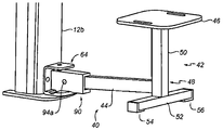
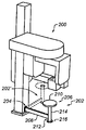
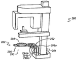
도 13a 및 도 13b는 지지 프레임(284)에 대하여 3차원으로 이동하도록, 예컨대 피봇 및 병진 이동하도록 구성된 다른 유형의 좌석 배치구조체(282)를 포함하는 장치(280)의 추가적인 실시형태를 예시한다.13A and 13B illustrate a further embodiment of an
좌석 배치구조체는 고정식 레일 구조체(292) 상에 슬라이드 가능하게 장착된 이동식 지지 구조체(290)에 결합되는 좌석부(288)를 갖는 좌석 조립체(286)를 포함한다. 이동식 지지 구조체(290)는, 그 2개의 대향 단부가 폐쇄되고 가이드 레일로서의 역할을 하는 레일 경로를 그 사이에 규정하는 2개의 세장형 부재 사이에 각각 위치된 사이드 롤러들을 포함한다. 레일 구조체(292)는 지지 프레임에 고정된다. 특히, 구조체(290)는 도 13a 및 도 13b에서 볼 수 있는 2 세트의 2개의 롤러(294a-d)를 포함하고 캐리지로서 기능한다. 각 세트의 각 롤러는 2개의 세장형 부재들(296a-b 및 296c-d)에 의해 규정되는 레일 경로 내부에 위치된다. 2 쌍의 세장형 부재들(296a-b 및 296c-d)은 각 세트의 2개의 롤러 사이의 거리에 대응하는 거리로부터 서로 횡방향으로 이격되어 있다. 2 쌍의 세장형 부재들(296a-b 및 296c-d)은 누운 자세에서 실질적으로 L자의 형태를 취하도록 형성된다. 따라서, 좌석 조립체(286)는 L 형상의 경로를 따라 도 13a의 작업 위치로부터 좌석 조립체가 수직으로 치워진 위치에 있는 도 13b의 휴지 위치로 수동으로 이동된다. 이러한 배치구조체는 사용하기 편리하고 콤팩트한 디자인을 제공한다. 지지 구조체(290) 및 고정식 레일 구조체(292)의 부재들은 중공 원통형 및 곡선형 튜브의 형태를 취할 수 있다.The seat arrangement includes a
도 14는 좌석 배치구조체(300)만이 도시된 추가적인 실시형태를 예시한다. 이 좌석 배치구조체는 장치의 지지 프레임에 대한 피봇 운동에 관해서는 도 1 내지 도 7의 좌석 배치구조체와 유사하다.14 illustrates a further embodiment where only the
좌석 배치구조체(300)는 좌석부(304) 및 지면 지지를 위한 다리 조립체(306)를 갖는 좌석 조립체(302)를 포함한다. 좌석 조립체(302)는 그 좌석부의 구성에 있어서 도 1 내지 도 7의 좌석 조립체(42)와 상이하다. 좌석부(304)는 도 14에서 알 수 있듯이 옆에서 보았을 때 환자가 앉는 수평 부분(304a)과 S자 또는 역 S자(반대쪽에서 본 경우) 형상의 하향 연장 부분(304b)을 포함한다. S자 또는 역 S자 형상의 상부 부위가 수평 부분(304a)을 형성하도록 수평방향으로 연장되는 것으로 고려될 수도 있다. S자 또는 역 S자 형상의 하부 부위는 좌석부에 앉은 환자를 위한 발판으로서의 역할을 한다.The
이 구성은 환자가 한 방향으로만 앉을 수 있기 때문에 도 10 및 도 11에서처럼 비대칭이다. 대조적으로, 다른 구성들은 환자가 여러 방향을 따라, 특히 대향하는 2개의 180° 방향으로 배향될 수 있게 한다.This configuration is asymmetrical as in FIGS. 10 and 11 because the patient can only sit in one direction. In contrast, other configurations allow the patient to be oriented along several directions, in particular in two opposite 180 ° directions.
다른 가능한 좌석 배치구조체 실시형태들이 본 발명의 범위 내에서 고려될 수 있다.Other possible seat arrangement embodiments may be considered within the scope of the present invention.
본원에 따른 특정한 예시적인 방법 및/또는 장치 실시형태들은 앞서 설명한 다양한 상이한 위치들(예컨대, 적어도 하나의 작업 위치 및 적어도 하나의 휴지 보관/휴지 위치) 사이에서 왕복하여 반복적으로 이동할 수 있는 예시적인 좌석 배치구조체를 제공할 수 있다. 본원에 따른 예시적인 실시형태들은 본 명세서에서 설명되는 다양한 특징들을 (개별적으로 또는 조합하여) 포함할 수 있다. 본 개시물의 실시형태들이 치과용 이미징 장치를 사용하여 예시되었지만, 유사한 원리가 다른 유형의 진단용 이미징 및 다른 해부학에 적용될 수 있다.Certain example method and / or device embodiments in accordance with the present disclosure are exemplary seats that can repeatedly move back and forth between the various different positions described above (eg, at least one working position and at least one rest storage / rest position). It is possible to provide a layout structure. Exemplary embodiments according to the present disclosure may include (individually or in combination) the various features described herein. Although embodiments of the present disclosure have been illustrated using a dental imaging device, similar principles can be applied to other types of diagnostic imaging and other anatomy.
본 발명은 하나 이상의 구현예에 관하여 예시되었지만, 첨부된 청구범위의 사상 및 범위로부터 일탈하는 일 없이, 예시된 실시예들에 대하여 변경 및/또는 수정이 이루어질 수 있다. 또한, 본 발명의 특정한 특징은 여러 구현예들/실시형태들 중 단지 하나에 관하여 개시되었을 수 있지만, 이러한 특징은 임의의 주어진 또는 특정한 기능에 대하여 바람직하고 유리할 수 있는 다른 구현예들/실시형태들의 하나 이상의 다른 특징들과 결합될 수 있다. "적어도 하나(at least one of)"라는 용어는 나열된 항목들 중 하나 이상을 선택할 수 있음을 의미하는 데 사용된다. "약(about)"이라는 용어는, 예시된 실시형태에 대하여 변경이 프로세스 또는 구조의 부적합을 초래하지 않는 한, 나열된 값이 다소 변경될 수 있음을 나타낸다. 마지막으로, "예시적인(exemplary)"이라는 용어는 설명이 이상적임을 의미하는 것이 아니라 예시로서 사용됨을 나타낸다. 본 발명의 다른 실시형태들은 본 명세서의 고찰 및 본 명세서에 개시된 발명의 실시로부터 당업자에게는 명백할 것이다. 본 명세서 및 실시예들은 단지 예시적인 것으로만 고려되며, 본 발명의 진정한 범위 및 사상은 적어도 이하의 청구범위에 의해 지시되는 것으로 의도된다.While the present invention has been illustrated with respect to one or more embodiments, changes and / or modifications may be made to the illustrated embodiments without departing from the spirit and scope of the appended claims. In addition, while a particular feature of the present invention may have been disclosed in terms of only one of several embodiments / embodiments, this feature may be of other embodiments / embodiments that may be desirable and advantageous for any given or particular function. It can be combined with one or more other features. The term "at least one of" is used to mean that one or more of the listed items can be selected. The term “about” indicates that, for the illustrated embodiment, the listed values may be changed somewhat, unless the change results in an incompatibility of the process or structure. Finally, the term "exemplary" does not mean that the description is ideal, but rather is used as an example. Other embodiments of the present invention will be apparent to those skilled in the art from a review of this specification and practice of the invention disclosed herein. It is intended that the specification and examples be considered as exemplary only, with a true scope and spirit of the invention being indicated by at least the following claims.
Claims (16)
― 지지 프레임,
― x-레이 소스 및 상기 x-레이 소스에 대응하는 적어도 하나의 x-레이 센서를 지지하며, 상기 지지 프레임에 대하여 이동 가능한 갠트리(gantry)를 포함하고,
상기 장치는 상기 지지 프레임에 연결되고 적어도 2개의 별개의 위치들 사이에서 이동 가능한 좌석 배치구조체를 더 포함하고, 상기 적어도 2개의 별개의 위치는:
상기 좌석 배치구조체가 상기 갠트리 아래의 작업 영역에 위치되는 작업 위치,
상기 갠트리 아래의 작업 영역을 비워두도록 상기 좌석 배치구조체가 상기 작업 영역으로부터 멀리 위치되는 적어도 하나의 휴지 위치인
치과용 이미징 장치.An extraoral dental imaging device for acquiring a radiographic image of a patient,
A support frame,
A gantry supporting an x-ray source and at least one x-ray sensor corresponding to the x-ray source, the gantry being movable relative to the support frame,
The apparatus further comprises a seating arrangement connected to the support frame and movable between at least two separate positions, wherein the at least two separate positions are:
A work position in which the seat arrangement is located in a work area below the gantry,
The seating arrangement is at least one resting position away from the work area to leave the work area below the gantry empty
Dental imaging device.
상기 좌석 배치구조체는 좌석 조립체 및 연결 아암을 포함하는
치과용 이미징 장치.The method of claim 1,
The seat arrangement includes a seat assembly and a connecting arm.
Dental imaging device.
상기 좌석 조립체는 좌석부 및 지면 지지를 위한 다리 조립체를 포함하는
치과용 이미징 장치.The method according to claim 1 or 2,
The seat assembly includes a seat assembly and a leg assembly for ground support.
Dental imaging device.
상기 좌석 배치구조체는 상기 지지 프레임에 대하여 피봇하도록 구성(최적의 모드 + C2)되는
치과용 이미징 장치.The method according to any one of claims 1 to 3,
The seat arrangement is configured to pivot about the support frame (optimal mode + C2)
Dental imaging device.
상기 좌석 배치구조체는 피봇식 조립체를 통해 상기 지지 프레임에 대하여 피봇하도록 구성되는
치과용 이미징 장치.The method of claim 4, wherein
The seat arrangement is configured to pivot relative to the support frame via a pivotal assembly.
Dental imaging device.
상기 지지 프레임은 상기 좌석 배치구조체의 상기 적어도 2개의 별개의 위치에 각각 대응하는 적어도 2개의 인덱싱된 위치를 포함하는 인덱싱된 면을 포함하고, 상기 좌석 배치구조체는 상기 피봇식 조립체를 통해 상기 인덱싱된 면에 대하여 피봇하여 하나의 인덱싱된 위치로부터 다른 인덱싱된 위치로 이동하도록 구성되는
치과용 이미징 장치.The method of claim 5,
The support frame includes an indexed face that includes at least two indexed positions, each corresponding to the at least two distinct positions of the seating arrangement, wherein the seating arrangement is indexed through the pivotal assembly. Configured to pivot about a face to move from one indexed position to another.
Dental imaging device.
상기 인덱싱된 면은 상기 좌석 배치구조체의 3개의 별개의 위치, 즉 상기 작업 위치 및 2개의 휴지 위치에 각각 대응하는 3개의 인덱싱된 위치를 포함하는
치과용 이미징 장치.The method of claim 6,
The indexed face includes three distinct positions of the seating arrangement, i.e. three indexed positions respectively corresponding to the work position and the two rest positions.
Dental imaging device.
상기 좌석 배치구조체는 적어도 하나의 탄성 부재를 통해 상기 인덱싱된 면에 대하여 가압되는
치과용 이미징 장치.The method according to claim 6 or 7,
The seat arrangement is pressed against the indexed face via at least one elastic member.
Dental imaging device.
상기 좌석 배치구조체는 상기 연결 아암을 상기 지지 프레임에 연결하는 연결 부재를 포함하고, 상기 연결 부재는 상기 피봇식 조립체를 통해 상기 인덱싱된 면에 대하여 일 단부가 피봇하여 하나의 인덱싱된 위치로부터 다른 인덱싱된 위치로 이동하도록 구성되는
치과용 이미징 장치.The method according to any one of claims 2 or 3 and 6 to 8,
The seating arrangement includes a connecting member for connecting the connecting arm to the support frame, the connecting member pivoting one end relative to the indexed face via the pivotal assembly to index another from one indexed position. Configured to go to a location
Dental imaging device.
상기 연결 부재는 그 반대쪽 단부가 상기 연결 아암의 제1 단부에 연결되고, 상기 연결 아암의 반대쪽의 제2 단부는 상기 좌석 조립체에 연결되는
치과용 이미징 장치.The method of claim 9,
The connecting member has an opposite end connected to the first end of the connecting arm, and a second end opposite the connecting arm is connected to the seat assembly.
Dental imaging device.
상기 연결 아암의 제1 단부는 상기 피봇식 조립체의 피봇 축을 포함하는 수직 평면에서 상기 연결 부재에 대하여 이동 가능하게 장착되는
치과용 이미징 장치.The method of claim 10,
The first end of the connecting arm is movably mounted with respect to the connecting member in a vertical plane including the pivot axis of the pivotal assembly.
Dental imaging device.
상기 연결 아암의 제1 단부는 적어도 하나의 탄성 부재를 통해 상향으로 가압되어, 상기 좌석 조립체 상에 환자가 없을 때 상기 연결 아암이 상부 휴지 위치로 가압되도록 하는
치과용 이미징 장치.The method of claim 11,
The first end of the connecting arm is urged upwards through at least one elastic member such that the connecting arm is urged to an upper rest position when there is no patient on the seat assembly.
Dental imaging device.
상기 연결 아암의 제1 단부는 상기 수직 평면에 수직인 피봇 축을 중심으로 상기 연결 부재에 대하여 피봇 가능하게 장착되는
치과용 이미징 장치.The method according to claim 11 or 12, wherein
The first end of the connecting arm is pivotally mounted relative to the connecting member about a pivot axis perpendicular to the vertical plane.
Dental imaging device.
상기 좌석 배치구조체는 상기 지지 프레임에 대하여 피봇 및 병진 이동하도록 구성(C4)되는
치과용 이미징 장치.The method according to any one of claims 1 to 3,
The seat arrangement is configured to pivot and translate (C4) relative to the support frame.
Dental imaging device.
상기 연결 아암은 힌지식 아암(C3)인
치과용 이미징 장치.The method according to claim 2 or 3,
The connecting arm is a hinged arm (C3)
Dental imaging device.
― 지지 프레임,
― x-레이 소스 및 상기 x-레이 소스에 대응하는 적어도 하나의 x-레이 센서를 지지하며, 상기 지지 프레임에 대하여 이동 가능한 갠트리,
― 상기 지지 프레임에 연결된 좌석 배치구조체를 포함하고,
상기 방법은 적어도 2개의 별개의 위치들 사이에서 상기 좌석 배치구조체를 이동시키는 단계를 포함하고, 상기 적어도 2개의 별개의 위치는:
상기 좌석 배치구조체가 상기 갠트리 아래의 작업 영역에 위치되는 작업 위치,
상기 갠트리 아래의 작업 영역을 비워두도록 상기 좌석 배치구조체가 상기 작업 영역으로부터 멀리 위치되는 휴지 위치인
방법.A method of using an extraoral dental imaging device to acquire a radiographic image of a patient, the device comprising:
A support frame,
A gantry supporting an x-ray source and at least one x-ray sensor corresponding to the x-ray source and movable relative to the support frame,
A seating arrangement connected to the support frame,
The method includes moving the seat arrangement between at least two distinct positions, wherein the at least two distinct positions are:
A work position in which the seat arrangement is located in a work area below the gantry,
The seating arrangement is a rest position away from the work area to leave the work area below the gantry empty.
Way.
Applications Claiming Priority (1)
| Application Number | Priority Date | Filing Date | Title |
|---|---|---|---|
| PCT/IB2016/002001 WO2018115922A1 (en) | 2016-12-22 | 2016-12-22 | A dental imaging apparatus with an integrated movable seat arrangement |
Publications (1)
| Publication Number | Publication Date |
|---|---|
| KR20190094458A true KR20190094458A (en) | 2019-08-13 |
Family
ID=58231653
Family Applications (1)
| Application Number | Title | Priority Date | Filing Date |
|---|---|---|---|
| KR1020197021242A KR20190094458A (en) | 2016-12-22 | 2016-12-22 | Dental Imaging Device With Integral Movable Seat Arrangement |
Country Status (6)
| Country | Link |
|---|---|
| US (1) | US20210128088A1 (en) |
| EP (1) | EP3558130B1 (en) |
| JP (1) | JP6952782B2 (en) |
| KR (1) | KR20190094458A (en) |
| CN (1) | CN110290748A (en) |
| WO (1) | WO2018115922A1 (en) |
Families Citing this family (2)
| Publication number | Priority date | Publication date | Assignee | Title |
|---|---|---|---|---|
| CN109512453A (en) * | 2019-01-22 | 2019-03-26 | 青岛市口腔医院 | A kind of endodontic treatment CBCT filming apparatus |
| TWI828591B (en) * | 2023-05-30 | 2024-01-01 | 中臺科技大學 | X-ray auxiliary frame and its intelligent control system |
Family Cites Families (13)
| Publication number | Priority date | Publication date | Assignee | Title |
|---|---|---|---|---|
| GB657944A (en) * | 1948-08-20 | 1951-09-26 | Wyatt Bentley Childs | Dentist's chair |
| US4044265A (en) * | 1976-03-05 | 1977-08-23 | General Electric Company | Mobile chair for panoramic dental x-ray machine |
| US4229656A (en) * | 1978-10-31 | 1980-10-21 | Pfizer Inc. | X-ray orienting apparatus |
| JPH0411692Y2 (en) * | 1985-11-30 | 1992-03-24 | ||
| JPH0438811Y2 (en) * | 1987-04-11 | 1992-09-10 | ||
| JP3055839B2 (en) * | 1992-07-07 | 2000-06-26 | 株式会社吉田製作所 | Dental panoramic tomography device |
| DE4404640C1 (en) * | 1994-02-14 | 1995-02-09 | Siemens Ag | Dental X-ray diagnosis equipment for the preparation of panoramic films of the skull of a patient |
| JP3207073B2 (en) * | 1994-04-13 | 2001-09-10 | 株式会社モリタ製作所 | X-ray equipment |
| JP3023700U (en) * | 1995-10-12 | 1996-04-23 | 株式会社モリタ製作所 | X-ray equipment |
| JP3328689B2 (en) * | 2000-10-13 | 2002-09-30 | 株式会社吉田製作所 | Dental CCD camera |
| CN2456542Y (en) * | 2001-01-11 | 2001-10-31 | 温凤美 | Adjustable computer table with chair |
| FI123978B (en) * | 2008-06-27 | 2014-01-15 | Planmeca Oy | Dental equipment |
| KR20100055975A (en) * | 2008-11-18 | 2010-05-27 | 주식회사바텍 | Dental x-ray ct photographing apparatus |
-
2016
- 2016-12-22 CN CN201680092105.1A patent/CN110290748A/en active Pending
- 2016-12-22 KR KR1020197021242A patent/KR20190094458A/en unknown
- 2016-12-22 EP EP16843260.7A patent/EP3558130B1/en active Active
- 2016-12-22 JP JP2019534651A patent/JP6952782B2/en active Active
- 2016-12-22 US US16/472,469 patent/US20210128088A1/en active Pending
- 2016-12-22 WO PCT/IB2016/002001 patent/WO2018115922A1/en unknown
Also Published As
| Publication number | Publication date |
|---|---|
| JP2020501844A (en) | 2020-01-23 |
| EP3558130A1 (en) | 2019-10-30 |
| US20210128088A1 (en) | 2021-05-06 |
| JP6952782B2 (en) | 2021-10-20 |
| WO2018115922A1 (en) | 2018-06-28 |
| EP3558130B1 (en) | 2024-02-28 |
| CN110290748A (en) | 2019-09-27 |
Similar Documents
| Publication | Publication Date | Title |
|---|---|---|
| KR101611682B1 (en) | X-ray imaging apparatus capable of shooting multi photographing modes | |
| US6382725B1 (en) | Examination chair with lifting and tilting mechanism | |
| KR101821940B1 (en) | Furniture member with powered mechanism providing lift and zero gravity positions | |
| KR101629290B1 (en) | A Electric Chair for Washing Hair | |
| KR20190094458A (en) | Dental Imaging Device With Integral Movable Seat Arrangement | |
| US20210369530A1 (en) | Integrated patient support and equipment for medical procedures | |
| JP2005124796A (en) | Headrest device and medical chair and medical bed equipped with the same | |
| JP4943417B2 (en) | Examining table | |
| JP6735203B2 (en) | Chest examination chair | |
| JP2001046365A (en) | Image diagnostic device | |
| JP7267301B2 (en) | Radiography system with lower shelf for standing and sitting patients | |
| JP4674732B2 (en) | Dental care equipment | |
| JP2006204444A (en) | Medical optical table | |
| US10898147B2 (en) | Adjustable lower shelf on an X-ray unit | |
| JP5349181B2 (en) | Patient chair and dental unit comprising the patient chair | |
| KR102319877B1 (en) | Unit chair | |
| CN212853968U (en) | Electric medical bed for obstetrical department | |
| JPH0438811Y2 (en) | ||
| US20080143075A1 (en) | Therapeutic wheelchair system | |
| JP2005124795A (en) | Armchair | |
| JP2000037381A (en) | X-ray radiographing device | |
| US10835441B2 (en) | Patient positioning apparatus with adjustable and lockable back rest | |
| JP2008080054A (en) | Multifunctional rest | |
| JPS6152703B2 (en) | ||
| JPH0257924B2 (en) |