KR20190077458A - A computer implemented method for configuring electronic relays in a distribution grid - Google Patents
A computer implemented method for configuring electronic relays in a distribution grid Download PDFInfo
- Publication number
- KR20190077458A KR20190077458A KR1020197015221A KR20197015221A KR20190077458A KR 20190077458 A KR20190077458 A KR 20190077458A KR 1020197015221 A KR1020197015221 A KR 1020197015221A KR 20197015221 A KR20197015221 A KR 20197015221A KR 20190077458 A KR20190077458 A KR 20190077458A
- Authority
- KR
- South Korea
- Prior art keywords
- electronic
- electronic relays
- relays
- configuration
- resources
- Prior art date
- Legal status (The legal status is an assumption and is not a legal conclusion. Google has not performed a legal analysis and makes no representation as to the accuracy of the status listed.)
- Granted
Links
Images


Classifications
-
- G—PHYSICS
- G05—CONTROLLING; REGULATING
- G05B—CONTROL OR REGULATING SYSTEMS IN GENERAL; FUNCTIONAL ELEMENTS OF SUCH SYSTEMS; MONITORING OR TESTING ARRANGEMENTS FOR SUCH SYSTEMS OR ELEMENTS
- G05B19/00—Program-control systems
- G05B19/02—Program-control systems electric
- G05B19/04—Program control other than numerical control, i.e. in sequence controllers or logic controllers
- G05B19/042—Program control other than numerical control, i.e. in sequence controllers or logic controllers using digital processors
- G05B19/0426—Programming the control sequence
-
- H—ELECTRICITY
- H02—GENERATION; CONVERSION OR DISTRIBUTION OF ELECTRIC POWER
- H02J—ELECTRIC POWER NETWORKS; CIRCUIT ARRANGEMENTS OR SYSTEMS FOR SUPPLYING OR DISTRIBUTING ELECTRIC POWER; SYSTEMS FOR STORING ELECTRIC ENERGY
- H02J13/00—Circuit arrangements for providing remote monitoring or remote control of equipment in a power distribution network
- H02J13/10—Circuit arrangements for providing remote monitoring or remote control of equipment in a power distribution network characterised by displaying of information or by user interaction, e.g. supervisory control and data acquisition [SCADA] systems
-
- H—ELECTRICITY
- H02—GENERATION; CONVERSION OR DISTRIBUTION OF ELECTRIC POWER
- H02J—ELECTRIC POWER NETWORKS; CIRCUIT ARRANGEMENTS OR SYSTEMS FOR SUPPLYING OR DISTRIBUTING ELECTRIC POWER; SYSTEMS FOR STORING ELECTRIC ENERGY
- H02J13/00—Circuit arrangements for providing remote monitoring or remote control of equipment in a power distribution network
- H02J13/13—Circuit arrangements for providing remote monitoring or remote control of equipment in a power distribution network characterised by the transmission of data to equipment in the power network
- H02J13/1311—Circuit arrangements for providing remote monitoring or remote control of equipment in a power distribution network characterised by the transmission of data to equipment in the power network using the power network as support for the transmission
-
- G—PHYSICS
- G05—CONTROLLING; REGULATING
- G05B—CONTROL OR REGULATING SYSTEMS IN GENERAL; FUNCTIONAL ELEMENTS OF SUCH SYSTEMS; MONITORING OR TESTING ARRANGEMENTS FOR SUCH SYSTEMS OR ELEMENTS
- G05B2219/00—Program-control systems
- G05B2219/20—Pc systems
- G05B2219/23—Pc programming
- G05B2219/23261—Use control template library
-
- G—PHYSICS
- G05—CONTROLLING; REGULATING
- G05B—CONTROL OR REGULATING SYSTEMS IN GENERAL; FUNCTIONAL ELEMENTS OF SUCH SYSTEMS; MONITORING OR TESTING ARRANGEMENTS FOR SUCH SYSTEMS OR ELEMENTS
- G05B2219/00—Program-control systems
- G05B2219/20—Pc systems
- G05B2219/25—Pc structure of the system
- G05B2219/25067—Graphic configuration control system
-
- Y—GENERAL TAGGING OF NEW TECHNOLOGICAL DEVELOPMENTS; GENERAL TAGGING OF CROSS-SECTIONAL TECHNOLOGIES SPANNING OVER SEVERAL SECTIONS OF THE IPC; TECHNICAL SUBJECTS COVERED BY FORMER USPC CROSS-REFERENCE ART COLLECTIONS [XRACs] AND DIGESTS
- Y02—TECHNOLOGIES OR APPLICATIONS FOR MITIGATION OR ADAPTATION AGAINST CLIMATE CHANGE
- Y02B—CLIMATE CHANGE MITIGATION TECHNOLOGIES RELATED TO BUILDINGS, e.g. HOUSING, HOUSE APPLIANCES OR RELATED END-USER APPLICATIONS
- Y02B70/00—Technologies for an efficient end-user side electric power management and consumption
- Y02B70/30—Systems integrating technologies related to power network operation and communication or information technologies for improving the carbon footprint of the management of residential or tertiary loads, i.e. smart grids as climate change mitigation technology in the buildings sector, including also the last stages of power distribution and the control, monitoring or operating management systems at local level
-
- Y02B70/3241—
-
- Y—GENERAL TAGGING OF NEW TECHNOLOGICAL DEVELOPMENTS; GENERAL TAGGING OF CROSS-SECTIONAL TECHNOLOGIES SPANNING OVER SEVERAL SECTIONS OF THE IPC; TECHNICAL SUBJECTS COVERED BY FORMER USPC CROSS-REFERENCE ART COLLECTIONS [XRACs] AND DIGESTS
- Y02—TECHNOLOGIES OR APPLICATIONS FOR MITIGATION OR ADAPTATION AGAINST CLIMATE CHANGE
- Y02B—CLIMATE CHANGE MITIGATION TECHNOLOGIES RELATED TO BUILDINGS, e.g. HOUSING, HOUSE APPLIANCES OR RELATED END-USER APPLICATIONS
- Y02B90/00—Enabling technologies or technologies with a potential or indirect contribution to GHG emissions mitigation
- Y02B90/20—Smart grids as enabling technology in buildings sector
-
- Y—GENERAL TAGGING OF NEW TECHNOLOGICAL DEVELOPMENTS; GENERAL TAGGING OF CROSS-SECTIONAL TECHNOLOGIES SPANNING OVER SEVERAL SECTIONS OF THE IPC; TECHNICAL SUBJECTS COVERED BY FORMER USPC CROSS-REFERENCE ART COLLECTIONS [XRACs] AND DIGESTS
- Y04—INFORMATION OR COMMUNICATION TECHNOLOGIES HAVING AN IMPACT ON OTHER TECHNOLOGY AREAS
- Y04S—SYSTEMS INTEGRATING TECHNOLOGIES RELATED TO POWER NETWORK OPERATION, COMMUNICATION OR INFORMATION TECHNOLOGIES FOR IMPROVING THE ELECTRICAL POWER GENERATION, TRANSMISSION, DISTRIBUTION, MANAGEMENT OR USAGE, i.e. SMART GRIDS
- Y04S20/00—Management or operation of end-user stationary applications or the last stages of power distribution; Controlling, monitoring or operating thereof
- Y04S20/20—End-user application control systems
-
- Y04S20/227—
Landscapes
- Engineering & Computer Science (AREA)
- Physics & Mathematics (AREA)
- General Physics & Mathematics (AREA)
- Automation & Control Theory (AREA)
- Power Engineering (AREA)
- User Interface Of Digital Computer (AREA)
- Emergency Protection Circuit Devices (AREA)
- Management, Administration, Business Operations System, And Electronic Commerce (AREA)
- Small-Scale Networks (AREA)
- Human Computer Interaction (AREA)
- Remote Monitoring And Control Of Power-Distribution Networks (AREA)
- Information Transfer Between Computers (AREA)
Abstract
배전 그리드 (250) 에서 하나 이상의 전자 릴레이들 (2) 을 구성하기 위한 방법 (100) 으로서, 상기 전자 릴레이들은 상기 배전 그리드의 대응하는 스위칭 디바이스들 (20) 에 동작적으로 연관되고, 방법 (100) 은 - 사용자에 의해 활성화 가능한 그래픽 리소스들 (11, 12, 13, 14, 15) 을 포함하는 그래픽 사용자 인터페이스 (110) 를 컴퓨터 디스플레이 (52) 상에 제공하는 단계; - 상기 전자 릴레이들을 구성하기 위한 대응하는 제어 로직 모델 (10A) 을 나타내는 구성 그래픽 템플릿 (10) 을 선택하기 위해 상기 그래픽 사용자 인터페이스 상에 제 1 그래픽 리소스들 (11) 을 제공하는 단계로서, 상기 제어 로직 모델은 구성 값들 (CF1, CF2) 의 대응하는 세트들에 의해 구성 가능한 하나 이상의 논리 소자들 (10B) 을 포함하는, 상기 제 1 그래픽 리소스들 (11) 을 제공하는 단계; - 선택된 구성 그래픽 템플릿 (10) 에 의해 표현된 제어 로직 모델 (10A) 의 하나 이상의 구성가능 논리 소자들 (10B) 을 구성하기 위한 제 2 그래픽 리소스들 (12) 을 제공하는 단계; - 하나 이상의 구성된 논리 소자들 (10B) 을 대응하는 전자 릴레이 (2) 에 연관시키기 위해 상기 그래픽 사용자 인터페이스 상에 제 3 그래픽 리소스들 (13) 을 제공하는 단계; - 상기 전자 릴레이들이 미리 정의된 동작 조건들을 충족시키는 지 여부를 확인하는 단계; - 상기 동작 조건들이 상기 전자 릴레이들에 의해 충족되는 경우, 상기 전자 릴레이들에 상기 구성 값들 (CF1, CF2) 을 포함하는 구성 정보를 전송하는 단계를 포함하는 것을 특징으로 한다.A method (100) for configuring one or more electronic relays (2) in a distribution grid (250), said electronic relays being operatively associated with corresponding switching devices (20) ) - Providing on the computer display (52) a graphical user interface (110) comprising user-activatable graphics resources (11, 12, 13, 14, 15); - providing first graphic resources (11) on said graphical user interface to select a configuration graphic template (10) representing a corresponding control logic model (10A) for constructing said electronic relays, Providing the first graphics resources (11), wherein the logic model comprises one or more logic elements (10B) configurable by corresponding sets of configuration values (CF1, CF2); - providing second graphics resources (12) for constituting one or more configurable logic elements (10B) of the control logic model (10A) represented by the selected configuration graphic template (10); - providing third graphics resources (13) on the graphical user interface to associate one or more configured logic elements (10B) with a corresponding electronic relay (2); - Confirming whether the electronic relays meet predefined operating conditions; And transmitting configuration information including the configuration values (CF1, CF2) to the electronic relays if the operating conditions are satisfied by the electronic relays.

Description
본 발명은 배전 그리들의 분야에 관한 것이다.The present invention relates to the field of distribution grids.
특히, 본 발명은 저전압 또는 중간 전압 레벨들에서 동작하는 배전 그리드의 전자 릴레이들을 구성하는 컴퓨터 구현 방법에 관한 것이다.In particular, the present invention relates to a computer implemented method of configuring electronic relays of a distribution grid operating at low or intermediate voltage levels.
본 출원의 목적으로, 용어 “저전압” (LV) 은 1 kV AC 및 1.5 kV DC 보다 낮은 동작 전압들에 관련되는 반면, “중간 전압” 은 예를 들어 72 kV AC 및 100 kV DC 까지의 수십 kV 까지의 동작 전압들에 관련된다.For purposes of the present application, the term " low voltage " (LV) relates to operating voltages less than 1 kV AC and 1.5 kV DC, whereas " intermediate voltage " refers to, for example, 72 kV AC and several tens kV ≪ / RTI >
배전 그리드들은 배전 그리드의 특정의 섹션들이 적절하게 동작하는 것을 가능하게 하도록 설계된 스위칭 디바이스들 (예를 들어, 회로 차단기들, 단로기들, 접촉기들 등) 을 포함한다.The distribution grids include switching devices (e.g., circuit breakers, disconnectors, contactors, etc.) designed to enable certain sections of the distribution grid to operate properly.
통상적으로, 상술된 스위칭 디바이스들은 적절한 센서들에 의해 스위칭기어의 동작 조건들을 확인하고, 배전 그리드들의 동작 조건들에 의해 요구될 때, 예를 들어 고장들 또는 과부하들의 경우에, 연관된 스위칭 디바이스들의 개입을 촉진하기 위해 적합한 커맨드들을 생성하도록 구성되는 전자 보호 및 제어 디바이스들 (이하, “전자 릴레이들” 로서 지칭됨) 과 동작적으로 연관된다.Typically, the above-described switching devices identify the operating conditions of the switching gear by appropriate sensors and, when required by operating conditions of the distribution grid, for example in the event of failures or overloads, (Hereinafter referred to as " electronic relays ") that are configured to generate appropriate commands to facilitate the operation of the system.
알려진 바와 같이, 전자 릴레이의 동작은 그의 기능들을 활용하기 위해 릴레이에 의해 저장되고 적절하게 프로세싱되는 동작 파미터들 (예를 들어, 보호 임계값들, 통신 파라미터들, 그리드 파라미터들 등) 의 세트에 의존한다.As is known, the operation of the electronic relay is controlled by a set of operation parameters (e.g., protection thresholds, communication parameters, grid parameters, etc.) stored and properly processed by the relay to utilize its functions It depends.
그러한 동작 파라미터들은 릴레이의 동작 수명 동안, 예를 들어 릴레이가 현장에 설치되거나 또는 유지보수 개입들 동안인 경우 적절하게 셋업될 (또는 널리 사용되는 용어에 따라 “구성될”) 필요가 있다. Such operating parameters need to be set up properly (or "configured" in accordance with widely used terms) during the operating lifetime of the relay, for example when the relay is installed in the field or during maintenance interventions.
배전 그리드들에서의 전자 릴레이들의 동작 파라미터들을 구성하기 위한 전통적인 솔루션들은 보통 릴레이들의 입력들 및 출력들을 획득하기 위한 시간 소비적인 케이블링 활동 및 릴레이들의 기능들을 모델링 및 셋업하기 위한 집중적인 프로그래밍 활동을 요구한다.Traditional solutions for constructing operating parameters of electronic relays in distribution grids usually require time-consuming cabling activities to acquire the inputs and outputs of the relays and intensive programming activities to model and set up the functions of the relays do.
모든 이들 활동들은 통상 전체 비용의 현저한 증가를 갖는 전문화된 인력의 개입을 수반한다.All of these activities usually involve the involvement of specialized personnel with a significant increase in overall costs.
또, 일반적으로, 릴레이들이 동작하기 시작하기 전에 릴레이들의 구성이 올바르게 수행되었는지 여부에 대한 예방적 정보를 획득하는 것은 불가능하다. 본 발명의 주요 목표는 상술된 기술적 문제들을 해결하거나 완화하는 것을 허용하는, 배전 그리드의 전자 릴레이들의 동작 파라미터들을 셋업하기 위한 방법을 제공하는 것이다.Also, it is generally not possible to obtain proactive information as to whether the configuration of the relays has been correctly performed before the relays start to operate. The main object of the present invention is to provide a method for setting operating parameters of electronic relays of a distribution grid, which allows to solve or mitigate the technical problems described above.
이러한 목표 내에서, 본 발명의 목적은 전자 릴레이들의 신속하고 효율적인 구성을 수행하는 방법을 제공하는 것이다.Within this aim, it is an object of the present invention to provide a method for performing a quick and efficient configuration of electronic relays.
본 발명의 다른 목적은 비전문화된 오퍼레이터들에 의해서도 용이하게 수행될 수 있는 방법을 제공하는 것이다.Another object of the present invention is to provide a method that can be easily performed by vision-cultured operators.
본 발명의 추가의 목적은 고가의 프로세싱 리소스들의 채택 없이 용이하게 컴퓨터 구현될 수 있는 방법을 제공하는 것이다.It is a further object of the present invention to provide a method that can be easily computerized without the need for expensive processing resources.
이들 목표 및 목적들은 다음의 청구항 1 및 관련된 종속항들에 따라, 배전 그리드에서의 전자 릴레이들의 동작 파라미터들을 셋업하는 방법에 의해 달성된다.These goals and objectives are achieved by a method for setting operating parameters of electronic relays in a distribution grid, according to
일반적인 정의에서, 본 발명에 따른 방법은 다음의 단계들을 포함한다:In a general definition, the method according to the invention comprises the following steps:
- 사용자에 의해 활성화 가능한 그래픽 리소스들을 포함하는 그래픽 사용자 인터페이스를 컴퓨터 디스플레이상에 제공하는 단계;- Providing on a computer display a graphical user interface comprising graphical resources activatable by a user;
- 구성 그래픽 템플릿을 선택하기 위해 상기 그래픽 사용자 인터페이스상에 제 1 그래픽 리소스들을 제공하는 단계로서, 상기 구성 그래픽 템플릿은 상기 전자 릴레이들을 구성하기 위한 대응하는 제어 로직 모델을 표현하고, 상기 제어 로직 모델은 구성 값들의 대응하는 세트들에 의해 구성가능한 하나 이상의 논리 소자들을 포함하는, 상기 제 1 그래픽 리소스들을 제공하는 단계; - Providing first graphic resources on the graphical user interface for selecting a configuration graphic template, the configuration graphic template representing a corresponding control logic model for configuring the electronic relays, the control logic model comprising: Providing the first graphics resources, wherein the first graphics resources comprise one or more logic elements configurable by corresponding sets of values;
- 선택된 구성 그래픽 템플릿에 의해 표현된 제어 로직 모델의 상기 하나 이상의 구성가능한 논리 소자들을 구성하기 위해 제 2 그래픽 리소스들을 제공하는 단계; - Providing second graphics resources to configure the one or more configurable logic elements of the control logic model represented by the selected configuration graphic template;
- 대응하는 전자 릴레이들에 하나 이상의 구성된 논리 소자들을 연관시키기 위해 상기 그래픽 사용자 인터페이스상에 제 3 그래픽 리소스들을 제공하는 단계; - Providing third graphics resources on the graphical user interface to associate one or more configured logic elements with corresponding electronic relays;
- 상기 전자 릴레이들이 미리 정의된 동작 조건들을 충족시키는지 여부를 확인하는 단계;- Confirming whether the electronic relays meet predefined operating conditions;
- 상기 동작 조건들이 상기 전자 릴레이들에 의해 충족되는 경우, 상기 전자 릴레이들에 상기 구성 값들을 포함하는 구성 정보를 송신하는 단계.- And transmitting configuration information including the configuration values to the electronic relays if the operating conditions are satisfied by the electronic relays.
바람직하게는, 상기 제 1 그래픽 리소스들은 하나 이상의 제 1 그래픽 오브젝트들을 포함하며, 각각의 제 1 그래픽 오브젝트는 상기 전자 릴레이들을 구성하기 위해 선택가능한 구성 그래픽 템플릿에 대응한다.Advantageously, said first graphics resources comprise one or more first graphic objects, and each first graphic object corresponds to a configurable graphic template selectable for configuring said electronic relays.
바람직하게는, 상기 제 2 그래픽 리소스들은 사용자가 상기 구성가능한 논리 소자들을 구성하기 위한 제 1 구성 값들을 제공하는 것을 돕기 위한 하나 이상의 제 2 그래픽 오브젝트들을 포함하며, 상기 제 1 구성 값들은 상기 전자 릴레이들에 의해 사용되는 글로벌 동작 파라미터들과 관련된다.Advantageously, the second graphics resources include one or more second graphic objects to help a user provide first configuration values for configuring the configurable logic elements, Lt; RTI ID = 0.0 > operational parameters < / RTI >
바람직하게는, 상기 제 2 그래픽 리소스들은 사용자가 상기 구성가능한 논리 소자들을 구성하기 위한 개개의 제 2 구성 값들을 제공하는 것을 돕기 위한 하나 이상의 제 3 그래픽 오브젝트들을 포함하며, 상기 제 2 구성 값들은 상기 전자 릴레이들에 의해 사용되는 개개의 동작 파라미터들과 관련된다.Advantageously, the second graphics resources include one or more third graphic objects to help a user provide individual second configuration values for configuring the configurable logic elements, Lt; / RTI > associated with the individual operating parameters used by the electronic relays.
바람직하게는, 상기 제 3 그래픽 리소스들은 사용자가 각각의 구성된 논리 소자를 대응하는 전자 릴레이에 연관시키는 것을 돕기 위한 하나 이상의 제 4 그래픽 오브젝트들을 포함한다.Advantageously, said third graphics resources include one or more fourth graphical objects for helping a user associate each configured logic element with a corresponding electronic relay.
바람직하게는, 상기 전자 릴레이들이 미리 정의된 동작 조건들을 충족시키는지 여부를 확인하는 단계는 사용자가 상기 전자 릴레이들에 의해 충족되는 동작 조건들과 관련된 정보를 획득하는 것을 돕기 위해 상기 그래픽 사용자 인터페이스상에 제 4 그래픽 리소스들을 제공하는 단계를 포함한다.Preferably, the step of verifying whether the electronic relays meet predefined operating conditions may include determining whether the graphical user interface < RTI ID = 0.0 > And providing fourth graphics resources to the second graphics processor.
바람직하게는, 상기 전자 릴레이들이 미리 정의된 동작 조건들을 충족시키는 지 여부를 확인하는 상기 단계는 사용자가 상기 전자 릴레이들의 상기 동작 조건들과 관련된 정보를 제공하는 것을 돕기 위해 상기 그래픽 사용자 인터페이스 상에 제 5 그래픽 리소스들을 제공하는 단계를 포함한다.Preferably, the step of verifying whether the electronic relays meet predefined operating conditions comprises the steps of: allowing the user to provide information relating to the operating conditions of the electronic relays, 5 graphics resources.
바람직하게는, 상기 구성 정보를 상기 전자 릴레이들로 전송하는 상기 단계는, 상기 전자 릴레이들로 상기 구성 값들의 전송을 가능하게 하는 코딩된 정보를 수신하는 단계, 상기 코딩된 정보를 확인하는 단계, 및 상기 코딩된 정보가 올바르다면 상기 전자 릴레이들에 상기 구성 정보를 전송하는 단계를 포함한다.Advantageously, said step of transmitting said configuration information to said electronic relays includes receiving coded information enabling transmission of said configuration values to said electronic relays, verifying said coded information, And transmitting the configuration information to the electronic relays if the coded information is correct.
추가의 양태에서, 본 발명은 다음의 청구항 9 에 따라, 컴퓨터 프로그램에 관한 것이다.In a further aspect, the present invention relates to a computer program according to the following claim 9.
추가의 양태에서, 본 발명은 다음의 청구항 10 에 따라, 컴퓨터 디바이스에 관한 것이다.In a further aspect, the present invention relates to a computer device according to the following claim.
바람직하게는, 상기 컴퓨터 디바이스는 하나 이상의 부속 디바이스들을 통해 상기 전자 릴레이들과 통신하도록 구성된다. 각각의 부속 디바이스는 대응하는 전자 릴레이에 포함되거나 동작적으로 커플링되고 상기 대응하는 전자 릴레이에 대한 인터넷 또는 LAN 또는 WAN 게이트웨이로서 동작하도록 구성된다.Advantageously, the computer device is configured to communicate with the electronic relays via one or more accessory devices. Each accessory device is included or operatively coupled to a corresponding electronic relay and is configured to operate as the Internet or LAN or WAN gateway to the corresponding electronic relay.
본 발명의 특성 및 이점은 첨부된 도면에 비제한적인 예들이 도시되어 있는 바람직하지만 배타적이지 않은 실시형태들의 설명으로부터 더욱 명백하게 드러날 것이며, 여기서:
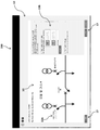
- 도 1 내지 도 3 은 본 발명의 일 양태에 따른 구성 방법을 구현하는 컴퓨터 디바이스를 도시하는 개략도이다;
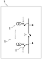
- 도 4 는 인터넷 또는 LAN 또는 WAN 게이트웨이로서 동작하는 부속 디바이스가 제공된 전자 릴레이와 동작적으로 연관된 스위칭 디바이스를 개략적으로 도시한다;
- 도 5 내지 도 11 은 본 발명에 따른 방법의 단계들을 보여주는 개략도들이다.The nature and advantages of the present invention will become more apparent from the description of the preferred but not exclusive embodiments in which non-limiting examples are shown in the accompanying drawings, in which:
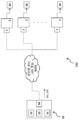
1 to 3 are schematic diagrams showing a computer device implementing a configuration method according to an aspect of the present invention;
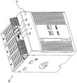
Figure 4 schematically shows a switching device operatively associated with an electronic relay provided with an accessory device operating as the Internet or a LAN or WAN gateway;
- Figures 5-11 are schematic diagrams showing the steps of the method according to the invention.
전술한 도면들을 참조하면, 본 발명은 바람직하게는 저전압 레벨에서 동작하는 배전 그리드 (250) 에서 하나 이상의 전자 릴레이들 (2) 을 구성하는 방법 (100) 을 참조한다. With reference to the above figures, the present invention preferably refers to a method 100 of configuring one or more
편리하게, 전자 릴레이들 (2) 은 배전 그리드 (250) 의 대응하는 스위칭 디바이스들 (20) (예를 들어, 회로 차단기, 단로기, 접촉기 등) 과 동작적으로 연관되어 이들 스위칭 디바이스들 (20) 을 제어한다. Conveniently, the
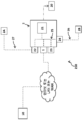
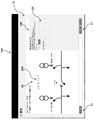
도 2 에서, 본 발명의 일부 실시형태들에 따른 전자 릴레이 (2) 가 개략적으로 도시되어 있다. In Figure 2, an
바람직하게는, 전자 릴레이 (2) 는 배전 그리드 (250) 의 동작 조건들과 관련된 데이터를 획득하고, 상기 동작 조건들을 확인하고, 비정상적인 조건들의 경우에, 예를 들어 고장들 또는 과부하들의 경우에 연관된 스위칭 디바이스 (20) 의 개입을 촉진하는 적절한 커맨드들을 제공하도록 구성된 제어 유닛 (21) 을 포함한다. Preferably, the
전자 릴레이 (2) 는 다양한 유형의 통신 버스 (25, 26, 27) 를 포함하거나 동작 적으로 커플링될 수도 있다The
예를 들어, 전자 릴레이 (2) 는 제어 유닛 (21) 과 전자 보호 릴레이 (2) 의 다른 부속 디바이스들 (1, 22, 23, 24) 사이에 통신 채널을 제공하도록 편리하게 설계된 로컬 버스 (25) 를 포함할 수도 있다. 로컬 버스 (25) 는 ETHERNET 과 같은 FIELDBUS 타입의 통신 프로토콜을 "멀티-마스터"타입의 통신 방식으로 구현할 수도 있다. For example, the
또 다른 예로서, 전자 릴레이 (2) 는 배전 그리드 (250) 의 시스템 버스 (27) 를 통해 추가의 수개의 전자 보호 디바이스들 (2A) 과 통신할 수도 있다. 시스템 버스 (27) 는 제어 유닛 (21) 과 릴레이 (2) 에 대해 원격 위치에 있을 수도 있는 다른 전자 디바이스들 (2A) (예를 들어, 다른 전자 릴레이들) 사이에 통신 채널을 제공하도록 편리하게 설계될 수도 있다. 시스템 버스 (27) 는 MODBUS, PROFIBUS, PROFINET 또는 MODBUS-TCP 타입의 통신 프로토콜을, "마스터-슬레이브" 타입의 통신 방식을 사용하여 구현할 수도 있다.As another example, the
또 다른 예로서, 전자 릴레이 (2) 는 릴레이 자신을 포함하는 스위치기어의 스위치보드 버스 (26) 를 통해 추가의 전자 디바이스들 (2B) 과 통신할 수 있다. 스위치보드 버스 (26) 는 보호 및 제어 유닛 (21) 과 상기 스위치기어의 다른 전자 디바이스들 (2B) (예를 들어, 다른 전자 릴레이들) 사이에 전용 통신 채널을 제공하도록 편리하게 설계된다. 스위치보드 버스 (26) 는 FIELDBUS 타입의 통신 프로토콜을 "멀티-마스터"타입의 통신 방식을 사용하여 구현할 수도 있다.As another example, the
전자 릴레이 (2) 는 제어 유닛 (21) 의 기능들을 (부속 디바이스 (1) 와 같이) 강화/확장시키고, (부속 디바이스들 (22, 24) 와 같이) 외부 통신 버스들을 향해 인터페이스를 제공하며, (부속 디바이스 (23) 와 같이) (디스플레이 또는 LED 인터페이스와 같은) 보호 및 제어 유닛 (21) 을 위한 보조 인터페이스를 제공하는 등을 위해 설계된 다양한 유형의 부속 디바이스를 포함하거나 동작적으로 커플링될 수도 있다. The
바람직하게는, 각각의 전자 릴레이 (2) 는 인터넷 또는 LAN 또는 WAN 통신 능력을 갖는 상기 전자 릴레이를 제공하도록 구성된 부속 디바이스 (1) 와 동작적으로 커플링된다.Preferably, each
바람직하게는, (부속 디바이스들 (22, 23, 24) 과 같이) 부속 디바이스 (1) 는 도 4 에 도시된 바와 같이 스위칭 디바이스 (20) 상의 대응하는 전자 보호 렐레이 (2) 와 함께 제거가능하게 장착되도록 구성된다.Advantageously, the accessory device 1 (such as
그러나, 다른 해결책들에 따르면, 부속 디바이스 (1) 는 대응하는 전자 보호 릴레이 (2) 가 자립 유닛인 경우, 이러한 전자 보호 릴레이 (2) 의 외부 케이스상에 제거가능하게 장착될 수도 있거나, 또는 대응하는 전자 릴레이 (2) 내에 통합된 내부 전자 모듈일 수도 있다.However, according to other solutions, the
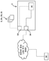
도 3 에서, 본 발명의 일부 실시형태들에 따른 부속 디바이스 (1) 가 개략적으로 도시되어 있다. In Fig. 3, an
바람직하게는, 부속 디바이스 (1) 는 대응하는 전자 릴레이 (2) 에 포함되거나 작동적으로 연결된 전자 디바이스들 (예를 들어, 제어 유닛 (21)) 과의 통신에 적합한 적어도 제 1 통신 포트 (1A) 를 포함한다. Preferably, the
예로서, 통신 포트 (1A) 는 대응하는 전자 릴레이 (2) 의 로컬 버스 (25) 와 동작적으로 커플링되기에 적합한 이더넷 포트일 수도 있다.For example, the
바람직하게는, 부속 디바이스 (1) 는 인터넷 또는 LAN 또는 WAN 을 통해 하나 이상의 원격 컴퓨터 장치 (50) 와 통신하기에 적합한 적어도 제 2 통신 포트 (1B) 를 포함한다. Preferably, the
예로서, 통신 포트 (1B) 는 인터넷 프로토콜 슈트에 적합한 TCP 또는 UDP 포트일 수도 있다.By way of example,
정보는 적절한 통신 케이블 (예를 들어, ETHERNET 유형) 또는 적절한 안테나 장치 (예를 들어, Wi-Fi 또는 Bluetooth 유형) 에 의해 인터넷 또는 LAN 또는 WAN 회선을 통해 전송될 수도 있다. The information may be transmitted over the Internet or over a LAN or WAN line by a suitable communication cable (e.g., ETHERNET type) or a suitable antenna device (e.g., Wi-Fi or Bluetooth type).
바람직하게는, 부속 디바이스 (1) 는 그의 동작을 관리하도록 구성된 대응하는 프로세싱 유닛 (1C) 을 포함한다. Preferably, the
부속 디바이스 (1) 는 전용 통신 버스 (예를 들어, 시스템 버스 (27)) 를 사용하거나 배치할 필요없이 인터넷 또는 LAN 또는 WAN 으로의 직접 접속을 대응하는 전자 릴레이 (2) 제공할 수 있다. The
즉, 부속 디바이스 (1) 는 릴레이 (2) (특히 그것의 보호 및 제어 유닛 (21)) 가 원격 컴퓨터 디바이스 (50) 와 직접 통신할 수 있는 인터넷 또는 LAN 또는 WAN 게이트웨이로서 동작하도록 구성된다. That is, the
전술한 바와 같이, 본 발명에 따른 방법 (100) 은 배전 그리드 (250) 의 전자 릴레이들 (2) 을 구성하는 방법이다.As described above, the method 100 according to the present invention is a method for constructing the
당업자에게 알려진 바와 같이, 전자 릴레이를 "구성하는 것" 은 상기 전자 릴레이의 기능들을 활용하기 위해 전자 릴레이에 의해 사용되는 동작 파라미터들 (예를 들어, 보호 임계 값, 통신 파라미터, 그리드 파라미터 등) 의 세트를 셋업하는 것에 있다.As is known to those skilled in the art, "configuring" an electronic relay is a function of the operating parameters (e.g., protection threshold, communication parameters, grid parameters, etc.) used by the electronic relay to utilize the functions of the electronic relay To set up a set.
상기 동작 파라미터들은 배전 그리드의 일반적인 동작 (글로벌 동작 파라미터들) 또는 전자 릴레이의 특정 동작 (개별 동작 파라미터들) 과 관련될 수도 있다.The operating parameters may be related to the general operation of the distribution grid (global operating parameters) or the specific operation of the electronic relay (individual operating parameters).
일반적으로, 전자 릴레이의 동작 파라미터들은 전자 릴레이 자체에 의해 저장 및 프로세싱될 수 있는 적절한 수치 또는 논리 값들 (구성 값들) 을 전자 릴레이에 제공함으로써 셋업될 수도 있다. In general, the operating parameters of the electronic relay may be set up by providing the electronic relay with appropriate numerical or logical values (configuration values) that can be stored and processed by the electronic relay itself.
다음의 설명으로부터 명백하게 알 수 있듯이, 본 발명에 따른 방법 (100) 은 컴퓨터 디바이스 (50) 에 의해 구현되는 데 특히 적합하고, 명료성을 위해, 이러한 종류의 구현에 대한 특정 참조로 이하에서 설명될 것이다.As will be apparent from the following discussion, the method 100 according to the present invention is particularly suitable for being implemented by the
일반적으로, 컴퓨터 디바이스 (50) 는 데스크톱 컴퓨터, 랩톱 컴퓨터, 태블릿, 스마트 폰 등과 같은 임의의 알려진 유형일 수도 있다.In general, the
컴퓨터 디바이스 (50) 는 본 발명에 따른 방법 (100) 을 구현하기 위해 소프트웨어 명령들 (510) 을 실행할 수 있는 (예를 들어, 하나 이상의 마이크로 프로세서들을 포함하는) 프로세싱 유닛 (51) 을 구비한다.The
컴퓨터 디바이스 (50) 는 소프트웨어 명령들 (510) 이 영구 저장되는 저장 메모리를 포함한다.The
대안으로서, 컴퓨터 디바이스 (50) 는 프로세싱 유닛 (51) 에 의한 실행을 위해 소프트웨어 명령들 (510) 이 업로드될 수도 있는 다른 메모리 지원과 동작적으로 연관될 수도 있다.Alternatively, the
컴퓨터 디바이스 (50) 는 프로세싱 유닛 (51) 에 의해 구동되는 디스플레이 (52) 를 포함하거나 동작적으로 연관된다.The
편리하게, 컴퓨터 디바이스 (50) 는 인터넷 또는 LAN 또는 WAN 통신 능력을 갖는다. 이를 위해, 인터넷 또는 LAN 또는 WAN 을 통해 원격 전자 디바이스들과 통신하기 위해 프로세싱 유닛 (51) 에 의해 구동되는 하나 이상의 통신 포트들 (54) (예를 들어, 이더넷 포트 또는 블루투스 포트 또는 Wi-Fi 포트) 이 구비된다.Conveniently, the
바람직하게는, 컴퓨터 디바이스 (50) 는 인터넷 또는 LAN 또는 WAN 을 통해 전자 릴레이들 (2) 과 이들 전자 릴레이들의 부속 디바이스들 (1) 에 의해 통신할 수 있으며, 각각의 부속 디바이스는 전술한 바와 같이 대응하는 전자 릴레이를 위한 인터넷 또는 LAN 또는 WAN 게이트웨이로서 동작하도록 구성된다.Preferably, the
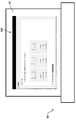
본 발명에 따르면, 방법 (100) 은 컴퓨터 디바이스 (50) 가 컴퓨터 디스플레이 (52) (도 5) 상에 그래픽 사용자 인터페이스 (190) 를 제공하는 단계를 포함한다. In accordance with the present invention, a method 100 includes the step of a
그래픽 사용자 인터페이스 (190) 는 사용자가 컴퓨터 디바이스 (50) 에 의해 전자 릴레이들 (2) 을 구성하는 것을 돕기 위해 시각적 그래픽 리소스들 (11, 12, 13, 14, 15) (예를 들어, 그래픽 아이콘, 그래픽 윈도우, 그래픽 커서, 시각적 표시기, 시각적 메뉴 등) 을 포함하는 시각적 그래픽 환경이다. The
일반적으로, 그래픽 리소스들 (11, 12, 13, 14, 15) 은 사용자가 컴퓨터 디바이스 (50) 에 대한 입력에서 대응하는 액션들을 실행하기 위한 특정 커맨드들 또는 릴레이들을 구성하기 위한 정보 (예를 들어, 구성 값들 CF1, CF2) 를 제공하는 것을 돕기 위해 이용가능하게 된다. In general, the
편리하게, 그래픽 리소스들 (11, 12, 13, 14, 15) 은 (예를 들어, 디스플레이 (52) 가 컴퓨터 모니터 또는 랩탑 디스플레이인 경우) 마우스 포인터를 통해 상기 그래픽 리소스들상을 클릭함으로써 또는 (예를 들어, 디스플레이 (52) 가 터치 스크린 디스플레이인 경우) 디스플레이 (52) 의 대응하는 상호 작용 영역들을 터치함으로써 컴퓨터 디바이스들에서 통상적으로 채택되는 기지의 활성화 모드들에 따라 활성화 가능하다. Conveniently, the
정보는 예를 들어 전용 그래픽 오브젝트들 (그래픽 커서, 그래픽 아이콘 등) 을 타이핑하거나 활성화함으로써 컴퓨터 디바이스들에서 일반적으로 채택 된 기지의 입력 모드들에 따라 사용자에 의해 입력될 수 있다. The information may be entered by the user in accordance with known input modes generally employed in computer devices, for example, by typing or activating dedicated graphics objects (graphic cursors, graphic icons, etc.).
바람직하게는, 그래픽 사용자 인터페이스 (190) 는 그래픽 리소스들 (11, 12, 13, 14, 15) 이 이용 가능하게 되는 하나 이상의 구성 페이지들을 포함한다.Preferably, the
바람직하게는, 그래픽 사용자 인터페이스 (190) 는 사용자가 상이한 구성 페이지들을 통해 이동하거나 저장 메모리 (53) 에/로부터 상기 구성 페이지들을 저장 또는 업로드하는 것을 허용하는 각각의 구성 페이지상의 보조 그래픽 리소스들 (17) (예를 들어, 그래픽 버튼들) 을 포함한다. Preferably, the
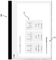
본 발명에 따르면, 방법 (100) 은 컴퓨터 디바이스 (50) 가 그래픽 사용자 인터페이스 (190) 상에 (바람직하게는 전용 구성 페이지 상에) 제 1 그래픽 리소스들 (11) 을 제공하여 전자 릴레이들 (2) 을 구성하기 위한 구성 그래픽 템플릿 (10) 을 선택하는 단계를 포함한다 (그림 6, 7).In accordance with the present invention, a method 100 is a method 100 in which a
구성 그래픽 템플릿 (10) 은 전자 릴레이들 (2) 을 구성하기 위한 대응하는 제어 로직 모델 (10A) 을 그래픽으로 나타낸다. The configuration
제어 로직 모델 (10A) 은 배전 그리드 (250) 에 의해, 및 보다 상세하게는 릴레이들 (2) 에 의해 구현되는 가능한 레이아웃 및 동작 모드를 기술한다.The
제어 로직 모드 (10A) 는 하나 이상의 논리 소자들 (10B) 을 포함하며, 각각은 적절한 구성 값들에 의해 구성 가능한 동작 파라미터의 대응하는 세트를 나타낸다.
구성 가능한 논리 소자 (10B) 는 상기 구성 값들에 의해 셋업되어야 하는 동작 파라미터들의 동일한 세트를 갖는 전자 릴레이를 편리하게 나타낸다. The
물론, 논리 소자 (10B) 의 구성 값들은 그 기능들을 활용하기 위해 상기 릴레이에 의해 사용되는 상술된 글로벌 동작 파라미터들 및 개별 동작 파라미터들와 관련될 수도 있다 Of course, the configuration values of
사용자는 하나 이상의 미리 정의된 구성 그래픽 템플릿들 (10) 중에서 주어진 구성 그래픽 템플릿 (10) 을 선택할 수 있다. The user can select a given configuration
그래픽 리소스들을 (11) 을 활성화시킴으로써, 다수의 이용 가능한 구성 그래픽 템플릿들 중에서 원하는 구성 그래픽 템플릿 (10) 을 취출하기 위해 선택 커맨드들이 컴퓨터 디바이스 (50) 에 전송된다.Selection commands are sent to the
편리하게, 구성 그래픽 템플릿 (10) 은 전자 릴레이 (2)의 구성 프로세스를 수행하기 전에 (예를 들어, 전자 릴레이 (2) 의 제공자에 의해) 설계 및 검증된다. Conveniently, the configuration
이러한 방식으로, 다수의 검증된 제어 로직 모델들 (10A) 이 사용자에게 이용 가능하게 될 수 있고, 사용자는 예를 들어 복잡한 프로그래밍 언어 (예를 들어, PLC 의 프로그래밍 언어) 를 사용하여 배전 그리드 (250) 의 동작을 시작 부터 모델링할 필요없이 전자 릴레이들 (2) 을 구성하기에 가장 적절한 것을 선택할 수 있다. In this way, a number of verified
이러한 방식으로, 배전 그리드 (250), 특히 전자 릴레이들 (2) 의 동작을 모델링하는데 있어서의 에러들이 회피되고, 릴레이들 (2) 의 구성 프로세스는 이 점에서 제한된 전문지식을 갖는 사용자에 의해서도 수행될 수 있다. In this way, errors in modeling the operation of the
검증된 구성 그래픽 템플릿들 (10) 은 이롭게는 저장 메모리 (53) 에 또는 등가의 메모리 지원에 영구적으로 저장되거나 또는 컴퓨터 (50) 와 (예를 들어, 인터넷 또는 LAN 또는 WAN 을 통해) 통신하는 추가의 컴퓨터 리소스 (도시되지 않음) 로부터 다운로드될 수 있는 라이브러리에 수집될 수 있다. The verified configuration
바람직하게는, 제 1 그래픽 리소스들 (11) 은 하나 이상의 그래픽 오브젝트들 (예를 들어, 그래픽 아이콘들) 을 포함하고, 각각의 그래픽 오브젝트는 전자 릴레이들 (2) 을 구성하기 위해 선택 가능한 미리 정의된 구성 그래픽 템플릿 (10) 에 대응한다.Advantageously, the
각 그래픽 오브젝트 (11) 는 대응하는 구성 그래픽 템플릿 (10) 을 취출하기 위해 사용자에 의해 활성화될 수 있다. 이러한 방식으로, 사용자는 보조된 방식으로 원하는 구성 그래픽 템플릿 (10) 을 선택할 수 있다.Each
본 발명에 따르면, 방법 (100) 은 컴퓨터화된 디바이스 (50) 가 사용자에 의한 그래픽 리소스들 (11) 의 활성화에 응답하여 그래픽 사용자 인터페이스 (190) 상에 (바람직하게는 그래픽 사용자 인터페이스의 하나 이상의 전용 구성 페이지들 상에) 선택된 구성 그래픽 템플릿 (10) 을 제공하는 단계를 포함한다 (도 8 내지 도 11).In accordance with the present invention, a method 100 is a method 100 in which a
본 발명에 따르면, 방법 (100) 은 컴퓨터화된 디바이스 (50) 가 그래픽 사용자 인터페이스 (190) 상에 선택된 구성 그래픽 템플릿 (10) 에 동작적으로 연관되는 제 2 그래픽 리소스들 (12) 을 제공하는 단계를 포함한다 (도 8 내지 도 9).In accordance with the present invention, a method 100 includes providing a
일반적으로, 제 2 그래픽 리소스들 (12) 은 사용자가 구성 가능한 논리 소자들 (10B) 을 구성하는 것을 돕도록 지향된다. In general, the
다시 말해서, 제 2 그래픽 리소스들 (12) 덕분에, 사용자는 구성 가능한 논리 소자들 (10) 을 구성하기 위해 구성 값들을 제공할 수 있다.In other words, thanks to the
바람직하게는, 제 2 그래픽 리소스들 (12) 은 선택된 구성 그래픽 템플릿 (10) 에 의해 표현된 제어 로직 모델 (10A) 의 구성가능 논리 소자들 (10B) 에 동작적으로 연관된다.Preferably, the
바람직하게는, 제 2 그래픽 리소스들 (12) 및 이들이 동작적으로 연관되는 선택된 구성 그래픽 템플릿 (10) 은 그래픽 사용자 인터페이스 (190) 의 전용 구성 페이지들상에서 이용 가능하게 된다. Preferably, the second
바람직하게는, 제 2 그래픽 리소스들 (12) 은 선택된 구성 그래픽 템플릿 (10) 에 의해 표현된 제어 로직 모델 (10A) 의 구성가능 논리 소자들 (10B) 을 구성하기 위한 제 1 구성 값들 (CF1) 을 사용자가 제공하는 것을 돕는 하나 이상의 제 2 그래픽 오브젝트들 (12A, 12B, 12C) 을 포함한다. The second
편리하게, 제 1 구성 값들 (CF1) 은 전자 릴레이들 (2) 에 의해 사용되는 글로벌 동작 파라미터들과 관련된 구성 값들이다. 더 자세하게는, 그것들은 전자 릴레이들 (2) 에 의해 사용되는 글로벌 동작 파라미터들에 대응하는 논리 소자들 (10B) 의 셋업 구성 파라미터들에 관한 것이다.Conveniently, the first configuration values CF1 are configuration values associated with global operating parameters used by the electronic relays 2. More specifically, they relate to the setup configuration parameters of the
도 8 에 도시 된 예에 따르면, 상기 제 2 그래픽 오브젝트들은 사용자에 의해 활성화 될 수 있는 (대응하는 제어 논리 소자에 동작적으로 연관된) 하나 이상의 그래픽 아이콘들 (12A) 을 포함할 수도 있다. According to the example shown in FIG. 8, the second graphic objects may include one or more
상기 제 2 그래픽 오브젝트들은 그래픽 아이콘들 (12A) 의 활성화에 응답하여 컴퓨터화된 디바이스 (50) 에 의해 제공되는 하나 이상의 그래픽 윈도우들 (12B) 을 더 포함할 수도 있다. 편리하게, 그래픽 윈도우들 (12B) 은 사용자가 보조된 방식으로 제 1 구성 값들을 셋업하는 것을 허용하는 추가의 아이콘들 및 커서들 (12C) 을 포함한다.The second graphic objects may further include one or
바람직하게는, 제 2 그래픽 오브젝트들 (12A, 12B, 12C) 및 이들이 동작적으로 연관되는 선택된 구성 그래픽 템플릿 (10) 은 그래픽 사용자 인터페이스 (190) 의 전용 구성 페이지상에서 이용 가능하게 된다. Preferably, the second
일단 제 1 구성 값들의 입력이 완료되면, 사용자는 적절한 보조 그래픽 리소스 (17) (예를 들어, 저장 버튼) 를 활성화시킴으로써 상기 구성 페이지 및 관련 구성 정보를 저장 메모리 (53) 에 저장할 수 있다.Once the input of the first configuration values is complete, the user may save the configuration page and associated configuration information in the
바람직하게는, 제 2 그래픽 리소스들 (12) 은 이전에 선택된 구성 그래픽 템플릿 (10) 에 의해 표현된 제어 로직 모델 (10A) 의 구성가능 논리 소자들 (10B) 을 구성하기 위한 제 2 구성 값들 (CF2) 을 사용자가 제공하는 것을 돕는 하나 이상의 제 3 그래픽 오브젝트들 (12D, 12E, 12F) 을 포함한다.Preferably, the
편리하게, 제 2 구성 값들 (CF2) 은 전자 릴레이들 (2) 에 의해 사용되는 개별 동작 파라미터들과 관련된 구성 값들이다. 더 자세하게는, 그것들은 전자 릴레이들 (2) 에 의해 사용되는 개별 동작 파라미터들에 대응하는 논리 소자들 (10B) 의 구성 파라미터들을 셋업하는 것에 관한 것이다.Conveniently, the second configuration values CF2 are configuration values associated with the individual operating parameters used by the electronic relays 2. More specifically, they relate to setting up the configuration parameters of the
도 9 에 도시된 예에 따르면, 언급된 제 3 그래픽 오브젝트들은 이롭게는 사용자에 의해 활성화 될 수 있는 (대응하는 제어 논리 소자에 동작적으로 연관된) 하나 이상의 그래픽 아이콘들 (12D) 을 포함할 수도 있다.According to the example shown in Figure 9, the mentioned third graphic objects may advantageously include one or more
상기 제 3 그래픽 오브젝트들은 그래픽 아이콘들 (12D) 의 활성화에 응답하여 컴퓨터화된 디바이스 (50) 에 의해 제공되는 하나 이상의 그래픽 윈도우 (12E) 를 더 포함할 수도 있다. 편리하게, 윈도우들 (12E) 은 사용자가 보조된 방식으로 제 2 구성 값들을 셋업하는 것을 허용하는 추가의 활성화 가능한 아이콘들 및 커서들 (12F) 을 포함한다.The third graphic objects may further include one or
바람직하게는, 제 3 그래픽 오브젝트들 (12D, 12E, 12F) 및 이들이 동작적으로 연관되는 선택된 구성 그래픽 템플릿 (10) 은 그래픽 사용자 인터페이스 (190) 의 전용 구성 페이지상에서 이용 가능하게 된다. Preferably, the third
일단 제 2 구성 값들의 입력이 완료되면, 사용자는 적절한 보조 그래픽 리소스 (17) (예를 들어, 저장 버튼) 를 활성화시킴으로써 상기 구성 페이지 및 관련 구성 정보를 저장 메모리 (53) 에 저장할 수 있다. Once the input of the second configuration values is completed, the user can save the configuration page and related configuration information in the
방법 (100) 의 이러한 단계에서, 구성 값들 (CF1, CF2) 의 하나 이상의 세트들은 선택된 구성 그래픽 템플릿 (10) 에 의해 표현된 제어 로직 모델 (10A) 의 대응하는 구성 가능한 논리 소자들 (10B) 에 연관된다.At this stage of the method 100 one or more sets of configuration values CF1 and CF2 are applied to corresponding
상술한 구성 단계들이 릴레이들 (2) 에 대한 개입 없이 제어 로직 모델 (10A) 에 대해 수행되었기 때문에, 구성 값들 (CF1, CF2) 의 각각의 세트는 아직 물리적 릴레이 (2) 와 연관되지 않는다는 것을 인지하는 것이 중요하다. It is to be noted that each set of configuration values CF1 and CF2 is not yet associated with the
본 발명에 따르면, 방법 (100) 은 컴퓨터 디바이스 (50) 가 선택된 구성 그래픽 템플릿 (10) 에 동작적으로 연관되는 제 3 그래픽 리소스들 (13) 을 그래픽 사용자 인터페이스 (190) 상에 제공하는 단계를 포함한다 (도 10).According to the present invention, a method 100 includes providing a
일반적으로, 제 3 그래픽 리소스들은 (13) 은 사용자가 대응하는 물리적 릴레이 (2) 에, 선택된 구성 그래픽 템플릿 (10) 에 의해 표현되는 제어 로직 모델 (10A) 의 각각의 구성된 논리 소자 (10B) 를 연관시키는 것을 돕도록 지향된다.In general, the third
다시 말해서, 제 3 그래픽 리소스들 (13) 덕분에, 사용자는 (제어 로직 모델 (10A) 의 구성가능한 논리 소자들 (10B) 을 구성하는데 사용되는) 구성 값들 (CF1, CF2) 의 각각의 세트를 대응하는 릴레이 (2) 와 연관시킬 수 있다.In other words, thanks to the third
바람직하게는, 제 3 그래픽 리소스들 (13) 및 이들이 동작적으로 연관되는 선택된 구성 그래픽 템플릿 (10) 은 그래픽 사용자 인터페이스 (190) 의 전용 구성 페이지상에서 이용 가능하게 된다. Preferably, the third
바람직하게는, 그래픽 리소스들 (13) 은 사용자가 각각의 구성 가능한 논리 소자 (10B) 를 대응하는 릴레이 (2) 와 연관시키는 것을 돕는 하나 이상의 제 4 그래픽 오브젝트들 (13A, 13B) 을 포함한다. Preferably, the
도 10 에 도시된 예에 따르면, 상기 제 4 그래픽 오브젝트들은 상술된 활성화 모드들 중 하나에 따라 사용자에 의해 활성화될 수 있는 (각각이 대응하는 제어 논리 소자 (10B) 에 동작적으로 연관되는) 하나 이상의 그래픽 아이콘들 (13A) 을 포함할 수도 있다.According to the example shown in FIG. 10, the fourth graphical objects may be activated by a user according to one of the above-mentioned activation modes (one of which is operatively associated with the corresponding
상기 제 4 그래픽 오브젝트들은 대응하는 전자 릴레이 (2) 에 관한 식별 정보를 각각 보고하는 그래픽 라벨들 (14C) 의 대응하는 리스트들을 포함하는 하나 이상의 그래픽 윈도우들 (13B) 을 더 포함할 수도 있다.The fourth graphic objects may further comprise one or
바람직하게는, 전자 릴레이들 (2) 에 관한 식별 정보는 전술한 구성 프로세스를 수행하기 전에 저장 메모리 (53) 에 (또는 다른 동등한 저장 서포트에) 저장된다.Preferably, the identification information about the
전자 릴레이들 (2) 에 관한 식별 정보는 (예를 들어, 그래픽 사용자 인터페이스 (190) 의 도시되지 않은 전용 입력 페이지 상에) 사용자 (2) 에 의해 직접 제공될 수도 있거나, 전자 릴레이들 (2) 과 인터넷 또는 LAN 또는 WAN 접속을 확립함으로써 이들 전자 릴레이들 (2) 로부터 컴퓨터화된 디바이스 (50) 에 의해 자동적으로 다운로드될 수 있다.The identification information on the
각각의 구성된 제어 논리 소자 (10B) 와 대응하는 전자 릴레이 (2) 사이의 연관은 선택적인 방식으로 대응하는 그래픽 아이콘 (13A) 및 대응하는 그래픽 라벨 (13B) 을 단순히 활성화시킴으로써 보조된 방식으로 사용자에 의해 수행될 수 있다. The association between each configured
그래픽 리소스들 (13A, 13B) 덕분에, 사용자는 각각의 구성된 제어 논리 소자 (10B) 를 대응하는 물리적 전자 릴레이 (2) 와 연관시키는 방법에 관한 링킹 (linking) 정보를 컴퓨터 디바이스 (50) 에 제공할 수 있다는 것이 상기한 것으로부터 분명하다. Thanks to the
따라서, 상기 링킹 정보는 제어 논리 소자 (10B) 에 관련된 구성 값들 (CF1, CF2) 의 각 세트를 대응하는 전자 릴레이 (2) 에 연관시키는 것을 가능하게 한다. The linking information thus makes it possible to associate each set of configuration values (CF1, CF2) associated with
바람직하게는, 그러한 링킹 정보는 저장 메모리 (53) (또는 다른 동등한 저장 서포트) 에 저장되고 언급된 구성 값들 (CF1, CF2) 을 전자 릴레이들 (2) 에 올바르게 전송하기 위해 컴퓨터화된 디바이스 (50) 에 의해 사용된다.Preferably, such linking information is stored in the storage memory 53 (or other equivalent storage support) and stored in the computerized device 50 (or other equivalent storage support) to properly transmit the mentioned configuration values CFl, CF2 to the electronic relays 2 ). ≪ / RTI >
본 발명에 따르면, 방법 (100) 은 컴퓨터 디바이스 (50) 가 미리 정의된 동작 조건들이 전자 릴레이들 (2) 에 의해 충족되는지 여부를 확인하는 단계를 포함한다.According to the present invention, the method 100 comprises the step of the
이러한 단계는 구성 파라미터들 (CF1, CF2) 의 전자 릴레이들 (2) 로의 후속적인 정확한 전송을 보장하고, 결과적으로 일단 전자 릴레이들이 적절하게 구성되면 전자 릴레이들의 신속한 조작성을 보장하므로 매우 유리하다. This step is very advantageous since it guarantees subsequent accurate transmission of the configuration parameters CF1, CF2 to the
바람직하게는, 상기 확인 단계는 전자 릴레이들 (2) 과의 통신 및 컴퓨터화된 디바이스 (50) 에 의한 각각의 전자 릴레이 (2) 의 질의를 확립한 때 컴퓨터화된 디바이스 (50) 에 의해 적어도 부분적으로 자동으로 수행된다. Advantageously, said checking step is performed by the
바람직하게는, 방법 (100) 은 컴퓨터 디바이스 (50) 가, 컴퓨터 디바이스 (50) 에 의해 자동 검사가 수행된 때에 상기 전자 릴레이 (2) 에 의해 충족되는 동작 조건과 관련된 정보를 사용자가 획득하는 것을 돕기 위해 그래픽 사용자 인터페이스 (190) 상에 제 4 그래픽 리소스들 (14) 을 제공하는 단계를 포함한다.Preferably, the method 100 further comprises that the
바람직하게는, 제 4 그래픽 리소스들 (14) 은 그래픽 사용자 인터페이스 (190) 의 전용 구성 페이지상의 선택된 구성 그래픽 템플릿 (10) 에 동작적으로 연관된다. Preferably, the
바람직하게는, 제 4 그래픽 리소스들 (14) 은 전자 릴레이들 (2) 에 관련된 정보를 디스플레이하는 하나 이상의 제 4 그래픽 오브젝트들 (14A) 을 포함한다.Preferably, the
도 11 에 도시된 예에 따르면, 상기 제 4 그래픽 오브젝트들은 전자 릴레이들 (2) 의 동작 조건들에 관한 정보를 각각 보고하는 그래픽 라벨들 (14B) 의 리스트를 포함하는 하나 이상의 그래픽 윈도우 (14A) 를 포함할 수도 있다.According to the example shown in FIG. 11, the fourth graphical objects include one or more
그러나, 전자 릴레이 (2) 의 동작 조건의 확인을 완료하기 위해, 사용자에 의해 제공된 정보를 확인하는 것이 필요할 수도 있다.However, in order to complete confirmation of the operating conditions of the
바람직하게는, 방법 (100) 은 컴퓨터 디바이스 (50) 가 전자 릴레이들 (2) 의 동작 조건들에 관련된 확인 정보를 사용자가 제공하는 것을 돕기 위해 그래픽 사용자 인터페이스 (190) 상에 제 4 그래픽 리소스들 (15) 을 제공하는 단계를 포함한다.Advantageously, the method 100 further comprises the steps of providing a
바람직하게는, 제 5 그래픽 리소스들 (15) 은 선택된 구성 그래픽 템플릿 (10) 에 동작적으로 연관된다.Preferably, the fifth
바람직하게는, 제 5 그래픽 리소스들 (15) 및 이들이 동작적으로 연관되는 선택된 구성 그래픽 템플릿 (10) 은 그래픽 사용자 인터페이스 (190) 의 전용 구성 페이지상에서 이용 가능하게 된다. Preferably, the fifth
바람직하게는, 제 5 그래픽 리소스들 (15) 은 사용자가 상기 확인 정보를 제공하는 것을 돕는 하나 이상의 제 5 그래픽 오브젝트들 (15A, 15B) 을 포함한다.Preferably, the fifth
도 11 에 도시된 예에 따르면, 상기 제 5 그래픽 오브젝트들은 전자 릴레이들 (2) 에 관한 미리 정의된 피스 (piece) 의 확인 정보를 각각 보고하는 그래픽 라벨들 (15B) 의 대응하는 리스트들을 포함하는 하나 이상의 그래픽 윈도우들 (15A) 을 포함할 수도 있다. According to the example shown in FIG. 11, the fifth graphical objects include corresponding lists of
확인 정보의 각 피스는 전자 릴레이 (2) 에 의해 충족되어야 하는 동작 조건을 편리하게 설명한다. Each piece of confirmation information conveniently describes the operating conditions that must be met by the
그래픽 라벨 (15B) 을 선택적으로 활성화시킴으로써, 사용자는 컴퓨터화된 디바이스 (50) 에, 확인 정보의 대응하는 피스가 정확하다는 것, 및 결과적으로 대응하는 요청된 동작 조건이 전자 릴레이 (2) 에 의해 충족된다는 것을 확인하는 커맨드들을 전송할 수 있다.By selectively activating the
일단 확인 정보의 입력이 완료되면, 사용자는 적절한 보조 그래픽 리소스 (17) (예를 들어, 저장 버튼) 를 활성화시킴으로써 대응하는 구성 페이지 및 관련 구성 정보를 저장 메모리 (53) 에 저장할 수 있다. Once the input of the confirmation information is complete, the user may save the corresponding configuration page and associated configuration information in the
이 때, 구성 값들 (CF1, CF2) 이 전자 릴레이 (2) 에 전송될 수 있다. At this time, the configuration values CF1 and CF2 can be transmitted to the
따라서, 방법 (100) 은 컴퓨터 디바이스 (50) 가 전자 릴레이 (2) 에 구성 값 (CF1, CF2) 를 포함하는 구성 정보를 전송하는 단계를 포함한다.The method 100 thus includes the step of the
구성 값 (CF1, CF2) 을 수신하면, 전자 릴레이 (2) 는 그 동작 파라미터를 적절하게 설정하고 동작을 시작할 수 있다.Upon reception of the configuration values CF1 and CF2, the
바람직하게는, 상기 구성 정보는 컴퓨터 장치 (50) 에 의해 인터넷 또는 LAN 또는 WAN 을 통해 전자 릴레이 (2) 로 전송된다.Preferably, the configuration information is transmitted by the
바람직하게는, 전자 릴레이 (2) 로의 상기 구성 정보의 전송은 인증 절차의 실행시에 발생한다.Preferably, the transfer of the configuration information to the
바람직하게는, 이러한 인증 절차는 컴퓨터 디바이스 (50) 가 전자 릴레이 (2) 로 구성 값의 전송을 가능하게 하기 위해 코딩된 정보를 수신하는 단계를 포함한다.Preferably, this authentication procedure comprises the step of the
이러한 코딩된 정보는 컴퓨터 디바이스 (50) 의 입력 포트 (도시되지 않음) 에 동작적으로 커플링된 메모리 서포트 (예를 들어, USB 저장 디바이스) 로부터 수신될 수도 있다.This coded information may be received from a memory support (e. G., A USB storage device) operatively coupled to an input port (not shown) of the
대안으로서, 그러한 코딩된 정보는 인터넷 또는 LAN 또는 WAN 을 통해 컴퓨터 디바이스 (50) 와 통신하는 원격 컴퓨터 소스로부터 수신될 수도 있다.Alternatively, such coded information may be received from a remote computer source that communicates with the
그러나 필요에 따라 다른 솔루션도 가능하다.However, other solutions are possible as needed.
바람직하게는, 이러한 인증 절차는 컴퓨터 디바이스 (50) 가 상기 코딩된 정보를 확인하여 그것이 올바른지 여부를 제어하는 단계를 포함한다.Preferably, this authentication procedure involves the
바람직하게는, 이러한 인증 절차는 컴퓨터 디바이스 (50) 가, 상기 코딩된 정보가 올바른 경우, 전자 릴레이들 (2) 로 상기 구성 정보를 전송하는 단계를 포함한다.Preferably, this authentication procedure involves the
본 발명에 따른 방법 (100) 은 전술한 목표 및 목적을 완전히 만족시키는 것을 허용한다. The method 100 according to the present invention allows to fully meet the objectives and objectives described above.
방법은 사용자가 배전 네트워크를 모델링하는데 경험이 적은 인원에 의해서도 수행될 수 있는 간단한 단계들로 전자식 릴레이들의 구성 프로세스를 보조된 방식으로 수행하는 것을 가능하게 한다.The method makes it possible to perform the construction process of the electronic relays in an assisted manner with simple steps that can be performed by even a less experienced person in modeling the distribution network.
릴레이의 구성은 미리 정의되고 검증된 제어 로직 모델을 참조로서 취함으로써 수행되므로 전자 릴레이들은 제한된 에러 확률을갖는 빠르고 효율적인 방식으로 구성될 수 있다.The configuration of the relay is performed by taking a predefined and verified control logic model as a reference, so that the electronic relays can be configured in a fast and efficient manner with a limited error probability.
방법은 인터넷 또는 LAN 또는 WAN 을 통해 전자 릴레이들 (2) 과 통신할 수 있는 컴퓨터 디바이스에 의한 구현에 특히 적합하다.The method is particularly suitable for implementation by a computer device capable of communicating with the
이것은 구성 프로세스 동안에 전자 릴레이들을 케이블링할 필요를 회피하거나 감소시키는 것을 허용한다.This allows to avoid or reduce the need to cable electronic relays during the configuration process.
Claims (11)
- 사용자에 의해 활성화가능한 그래픽 리소스들 (11, 12, 13, 14, 15) 을 포함하는 그래픽 사용자 인터페이스 (110) 를 컴퓨터 디스플레이 (52) 상에 제공하는 단계;
- 상기 전자 릴레이들을 구성하기 위한 대응하는 제어 로직 모델 (10A) 을 나타내는 구성 그래픽 템플릿 (10) 을 선택하기 위해 상기 그래픽 사용자 인터페이스 상에 제 1 그래픽 리소스들 (11) 을 제공하는 단계로서, 상기 제어 로직 모델은 구성 값들 (CF1, CF2) 의 대응하는 세트들에 의해 구성 가능한 하나 이상의 논리 소자들 (10B) 을 포함하는, 상기 제 1 그래픽 리소스들 (11) 을 제공하는 단계;
- 선택된 구성 그래픽 템플릿 (10) 에 의해 표현된 제어 로직 모델 (10A) 의 하나 이상의 구성가능 논리 소자들 (10B) 을 구성하기 위한 제 2 그래픽 리소스들 (12) 을 제공하는 단계;
- 하나 이상의 구성된 논리 소자들을 대응하는 전자 릴레이들 (2) 에 연관시키기 위해 상기 그래픽 사용자 인터페이스 상에 제 3 그래픽 리소스들 (13) 을 제공하는 단계;
- 상기 전자 릴레이들이 미리 정의된 동작 조건들을 충족시키는 지 여부를 확인하는 단계;
- 상기 동작 조건들이 상기 전자 릴레이들에 의해 충족되는 경우, 상기 전자 릴레이들에 상기 구성 값들 (CF1, CF2) 을 포함하는 구성 정보를 전송하는 단계를 포함하는 것을 특징으로 하는 전자 릴레이들을 구성하기 위한 방법.A method (100) for configuring one or more electronic relays (2) in a distribution grid (250), said electronic relays being operatively associated with corresponding switching devices (20)
- providing on the computer display (52) a graphical user interface (110) comprising graphical resources (11, 12, 13, 14, 15) activatable by the user;
- providing first graphic resources (11) on said graphical user interface to select a configuration graphic template (10) representing a corresponding control logic model (10A) for constructing said electronic relays, Providing the first graphics resources (11), wherein the logic model comprises one or more logic elements (10B) configurable by corresponding sets of configuration values (CF1, CF2);
- providing second graphics resources (12) for constituting one or more configurable logic elements (10B) of the control logic model (10A) represented by the selected configuration graphic template (10);
- providing third graphics resources (13) on the graphical user interface to associate one or more configured logic elements with corresponding electronic relays (2);
- confirming whether said electronic relays meet predefined operating conditions;
- transmitting configuration information including said configuration values (CF1, CF2) to said electronic relays if said operating conditions are satisfied by said electronic relays Way.
상기 제 1 그래픽 리소스들은 하나 이상의 제 1 그래픽 오브젝트들 (11) 을 포함하고, 상기 제 1 그래픽 오브젝트들 각각은 상기 전자 릴레이들을 구성하기 위해 선택 가능한 구성 그래픽 템플릿 (10) 에 대응하는 것을 특징으로 하는 전자 릴레이들을 구성하기 위한 방법.The method according to claim 1,
Characterized in that the first graphic resources comprise one or more first graphic objects (11), each of the first graphic objects corresponding to a configurable graphic template (10) selectable for constituting the electronic relays A method for constructing electronic relays.
상기 제 2 그래픽 리소스들 (12)은,
- 상기 전자 릴레이들 (2) 에 의해 사용되는 글로벌 동작 파라미터들에 관련되는, 상기 구성 가능한 논리 소자들을 구성하기 위한 제 1 구성 값들을 사용자가 제공하는 것을 돕는 하나 이상의 제 2 그래픽 오브젝트들 (12A, 12B, 12C);
- 상기 전자 릴레이들 (2) 에 의해 사용되는 개개의 동작 파라미터들에 관련되는, 상기 구성 가능한 논리 소자들을 구성하기 위한 개개의 제 2 구성 값들을 사용자가 제공하는 것을 돕는 하나 이상의 제 3 그래픽 오브젝트들 (12D, 12E, 12F) 을 포함하는 것을 특징으로 하는 전자 릴레이들을 구성하기 위한 방법.3. The method according to claim 1 or 2,
The second graphics resources (12)
- one or more second graphic objects (12A, 12B) that help the user provide first configuration values for configuring the configurable logic elements, associated with global operating parameters used by the electronic relays (2) 12B, 12C);
- one or more third graphics objects (1), which help the user to provide individual second configuration values for configuring the configurable logic elements, related to the individual operating parameters used by the electronic relays (2) (12D, 12E, 12F). ≪ / RTI >
상기 제 3 그래픽 리소스들 (13) 은 사용자가 각각의 구성된 논리 소자를 대응하는 전자 릴레이 (2) 에 연관시키는 것을 돕는 하나 이상의 제 4 그래픽 오브젝트들 (13A, 13B) 을 포함하는 것을 특징으로 하는 전자 릴레이들을 구성하기 위한 방법.4. The method according to any one of claims 1 to 3,
Characterized in that the third graphics resources (13) comprise one or more fourth graphic objects (13A, 13B) which help the user to associate each configured logic element with a corresponding electronic relay (2) Method for configuring relays.
상기 전자 릴레이들 (2) 이 미리 정의된 동작 조건들을 충족시키는 지 여부를 확인하는 상기 단계는 사용자가 상기 전자 릴레이들에 의해 충족되는 동작 조건들과 관련된 정보를 획득하는 것을 돕기 위해 상기 그래픽 사용자 인터페이스 상에 제 4 그래픽 리소스들 (14) 을 제공하는 단계를 포함하는 것을 특징으로하는 전자 릴레이들을 구성하기 위한 방법.5. The method according to any one of claims 1 to 4,
Wherein the step of verifying whether the electronic relays (2) meet predefined operating conditions comprises the steps of: (a) providing a graphical user interface (GUI) to help the user obtain information related to operating conditions satisfied by the electronic relays And providing fourth graphics resources (14) on the second graphics resource (14).
상기 전자 릴레이들 (2) 이 미리 정의된 동작 조건들을 충족시키는 지 여부를 확인하는 상기 단계는 사용자가 상기 전자 릴레이들의 상기 동작 조건들과 관련된 정보를 제공하는 것을 돕기 위해 상기 그래픽 사용자 인터페이스 상에 제 5 그래픽 리소스들 (15) 을 제공하는 단계를 포함하는 것을 특징으로하는 전자 릴레이들을 구성하기 위한 방법.6. The method according to any one of claims 1 to 5,
Wherein the step of verifying whether the electronic relays (2) meet predefined operating conditions comprises the steps of: allowing the user to provide information relating to the operating conditions of the electronic relays 5. The method of claim 1, further comprising providing graphical resources (15).
상기 구성 정보는 인터넷 또는 LAN 또는 WAN 을 통해 상기 전자 릴레이들 (2) 로 전송되는 것을 특징으로하는 전자 릴레이들을 구성하기 위한 방법.7. The method according to any one of claims 1 to 6,
Wherein the configuration information is transmitted to the electronic relays (2) via the Internet or a LAN or WAN.
상기 구성 정보를 상기 전자 릴레이들 (2) 로 전송하는 상기 단계는,
- 상기 전자 릴레이들로 상기 구성 정보의 전송을 가능하게 하는 코딩된 정보를 수신하는 단계;
- 상기 코딩된 정보를 확인하는 단계;
- 상기 코딩된 정보가 올바르다면 상기 전자 릴레이들에 상기 구성 정보를 전송하는 단계를 포함하는 것을 특징으로 하는 전자 릴레이들을 구성하기 위한 방법.8. The method according to any one of claims 1 to 7,
Wherein the step of transmitting the configuration information to the electronic relays (2)
- receiving coded information enabling the transmission of the configuration information to the electronic relays;
- confirming the coded information;
And - if said coded information is correct, transmitting said configuration information to said electronic relays.
소프트웨어 명령들이 컴퓨터 디바이스 (50) 에 의해 실행될 때, 제 1 항 내지 제 8 항 중 어느 한 항에 따른 방법 (1) 을 구현하도록 구성된 상기 소프트웨어 명령들을 포함하는 것을 특징으로하는 컴퓨터 프로그램.A computer program that can be stored on or stored in a storage medium,
9. A computer program comprising the software instructions configured to implement the method (1) according to any one of claims 1 to 8 when the software instructions are executed by the computer device (50).
하나 이상의 부속 디바이스들 (1) 을 통해 상기 전자 릴레이들 (2) 과 통신하도록 구성되고, 각각의 부속 디바이스는 대응하는 전자 릴레이에 포함되거나 동작적으로 커플링되고 상기 대응하는 전자 릴레이에 대한 인터넷 또는 LAN 또는 WAN 게이트웨이로서 동작하도록 구성되는 것을 특징으로 하는 컴퓨터 디바이스 (50).11. The method of claim 10,
Each associated device being included in or operatively coupled to a corresponding electronic relay and configured to communicate with the corresponding electronic relay (2) via one or more accessory devices (1) A computer device (50) characterized by being configured to operate as a LAN or WAN gateway.
Applications Claiming Priority (3)
| Application Number | Priority Date | Filing Date | Title |
|---|---|---|---|
| EP16197701.2 | 2016-11-08 | ||
| EP16197701.2A EP3318936B1 (en) | 2016-11-08 | 2016-11-08 | A computer-implemented method for configuring electronic relays in an electric power distribution grid |
| PCT/EP2017/076739 WO2018086840A1 (en) | 2016-11-08 | 2017-10-19 | A computer-implemented method for configuring electronic relays in an electric power distribution grid |
Publications (2)
| Publication Number | Publication Date |
|---|---|
| KR20190077458A true KR20190077458A (en) | 2019-07-03 |
| KR102385281B1 KR102385281B1 (en) | 2022-04-08 |
Family
ID=57348470
Family Applications (1)
| Application Number | Title | Priority Date | Filing Date |
|---|---|---|---|
| KR1020197015221A Active KR102385281B1 (en) | 2016-11-08 | 2017-10-19 | A computer implemented method of configuring electronic relays in a distribution grid |
Country Status (6)
| Country | Link |
|---|---|
| US (1) | US11018522B2 (en) |
| EP (1) | EP3318936B1 (en) |
| JP (1) | JP6998950B2 (en) |
| KR (1) | KR102385281B1 (en) |
| ES (1) | ES2947504T3 (en) |
| WO (1) | WO2018086840A1 (en) |
Families Citing this family (3)
| Publication number | Priority date | Publication date | Assignee | Title |
|---|---|---|---|---|
| CN109934513B (en) * | 2019-04-01 | 2021-06-01 | 河海大学 | Irregular Lingang Industrial Zone Layout System and Method Based on Multi-agent Evolutionary Algorithm |
| US20240103850A1 (en) * | 2022-09-27 | 2024-03-28 | Rockwell Automation Technologies, Inc. | Presentation design to background service binding |
| US12566603B2 (en) | 2022-09-27 | 2026-03-03 | Rockwell Automation Technologies, Inc. | Presentation design to automation device binding |
Citations (1)
| Publication number | Priority date | Publication date | Assignee | Title |
|---|---|---|---|---|
| US20030061335A1 (en) * | 1999-09-16 | 2003-03-27 | Thomas Robert P. | Virtual modular relay device |
Family Cites Families (9)
| Publication number | Priority date | Publication date | Assignee | Title |
|---|---|---|---|---|
| JP3619336B2 (en) * | 1996-09-25 | 2005-02-09 | 松下電工株式会社 | Remote monitoring and control system |
| EP1359482A1 (en) * | 2002-05-01 | 2003-11-05 | Ge Fanuc Automation North America, Inc. | Power builder for power management control system automation software |
| US7640291B2 (en) * | 2002-12-16 | 2009-12-29 | Rockwell Automation Technologies, Inc. | Agent-equipped controller having data table interface between agent-type programming and non-agent-type programming |
| US7146232B2 (en) * | 2002-12-16 | 2006-12-05 | Rockwell Automation Technologies, Inc. | Agent program environment |
| US7305272B2 (en) * | 2002-12-16 | 2007-12-04 | Rockwell Automation Technologies, Inc. | Controller with agent functionality |
| US7627453B2 (en) * | 2005-04-26 | 2009-12-01 | Current Communications Services, Llc | Power distribution network performance data presentation system and method |
| US20130211610A1 (en) * | 2010-07-23 | 2013-08-15 | Siemens Aktiengesellschaft | Configuring of a field device in an arragement for distribution of electric energy |
| JP6050757B2 (en) * | 2010-11-15 | 2016-12-21 | ブルーム エナジー コーポレーション | Fuel cell system capable of independent operation with DC microgrid function |
| WO2014205119A1 (en) * | 2013-06-18 | 2014-12-24 | The Regents Of The University Of Colorado, A Body Corporate | Software-defined energy communication networks |
-
2016
- 2016-11-08 EP EP16197701.2A patent/EP3318936B1/en active Active
- 2016-11-08 ES ES16197701T patent/ES2947504T3/en active Active
-
2017
- 2017-10-19 KR KR1020197015221A patent/KR102385281B1/en active Active
- 2017-10-19 US US16/348,303 patent/US11018522B2/en active Active
- 2017-10-19 WO PCT/EP2017/076739 patent/WO2018086840A1/en not_active Ceased
- 2017-10-19 JP JP2019523706A patent/JP6998950B2/en active Active
Patent Citations (1)
| Publication number | Priority date | Publication date | Assignee | Title |
|---|---|---|---|---|
| US20030061335A1 (en) * | 1999-09-16 | 2003-03-27 | Thomas Robert P. | Virtual modular relay device |
Also Published As
| Publication number | Publication date |
|---|---|
| US11018522B2 (en) | 2021-05-25 |
| EP3318936B1 (en) | 2023-03-22 |
| EP3318936A1 (en) | 2018-05-09 |
| WO2018086840A1 (en) | 2018-05-17 |
| US20190280522A1 (en) | 2019-09-12 |
| JP2020504857A (en) | 2020-02-13 |
| KR102385281B1 (en) | 2022-04-08 |
| JP6998950B2 (en) | 2022-01-18 |
| ES2947504T3 (en) | 2023-08-10 |
Similar Documents
| Publication | Publication Date | Title |
|---|---|---|
| US20110302511A1 (en) | Method for providing an operating menu for a field device of process automation technology | |
| JP2019179548A (en) | System and method for managing alert associated with device of process control system | |
| US10511159B2 (en) | Computer-implemented method for configuring an electronic relay | |
| US20140067148A1 (en) | Configuration of the communication links of field devices in a power automation installation | |
| KR102385281B1 (en) | A computer implemented method of configuring electronic relays in a distribution grid | |
| JP2018153073A (en) | A computerized system for managing the operation of a power distribution network and a configuration method thereof. | |
| CN104008446A (en) | Construction technology information interactive method and system | |
| JPWO2015170408A1 (en) | Monitoring control system, monitoring terminal and monitoring program | |
| CN113986270B (en) | Distributed application deployment method and device, storage medium and electronic equipment | |
| CN102007471B (en) | Method and apparatus for designing device-to-device configurations suitable for use in power systems | |
| KR102076754B1 (en) | Diagnostic system for control logic and method for diagnosing the same | |
| CN109765850B (en) | Control system | |
| JP2009095197A (en) | Distant monitoring and control device simulation device and power system monitoring and control system | |
| CN116167724A (en) | Method, device, equipment and storage medium for realizing process automation | |
| CN113545013B (en) | Network management device, management method, and recording medium | |
| JP5360382B2 (en) | PLC program development support device | |
| US8082500B2 (en) | Method and apparatus for communicating with an intelligent electronic device associated to a switching device in power systems | |
| JP2017220107A (en) | Apparatus setting device, apparatus setting method, and program | |
| EP2853969A1 (en) | An alarm management system and a method therefor | |
| CN105446280A (en) | Industrial process control fast generation system and implementation method thereof | |
| JP6574389B2 (en) | KVM switch | |
| EP3299950A1 (en) | Display screen generating device, display screen generating method, and display screen generating program | |
| US20200374198A1 (en) | Control method, control device, control system and recording medium | |
| JP2015011600A (en) | Engineering device and associated control device specification method | |
| HK40034218A (en) | Method and apparatus for creating and managing smart programmable logic controller (plc) solutions |
Legal Events
| Date | Code | Title | Description |
|---|---|---|---|
| PA0105 | International application |
Patent event date: 20190527 Patent event code: PA01051R01D Comment text: International Patent Application |
|
| PG1501 | Laying open of application | ||
| A201 | Request for examination | ||
| AMND | Amendment | ||
| PA0201 | Request for examination |
Patent event code: PA02012R01D Patent event date: 20200706 Comment text: Request for Examination of Application |
|
| E902 | Notification of reason for refusal | ||
| PE0902 | Notice of grounds for rejection |
Comment text: Notification of reason for refusal Patent event date: 20210719 Patent event code: PE09021S01D |
|
| AMND | Amendment | ||
| E601 | Decision to refuse application | ||
| PE0601 | Decision on rejection of patent |
Patent event date: 20220113 Comment text: Decision to Refuse Application Patent event code: PE06012S01D Patent event date: 20210719 Comment text: Notification of reason for refusal Patent event code: PE06011S01I |
|
| X091 | Application refused [patent] | ||
| AMND | Amendment | ||
| PX0901 | Re-examination |
Patent event code: PX09011S01I Patent event date: 20220113 Comment text: Decision to Refuse Application Patent event code: PX09012R01I Patent event date: 20210916 Comment text: Amendment to Specification, etc. Patent event code: PX09012R01I Patent event date: 20200706 Comment text: Amendment to Specification, etc. |
|
| PX0701 | Decision of registration after re-examination |
Patent event date: 20220304 Comment text: Decision to Grant Registration Patent event code: PX07013S01D Patent event date: 20220214 Comment text: Amendment to Specification, etc. Patent event code: PX07012R01I Patent event date: 20220113 Comment text: Decision to Refuse Application Patent event code: PX07011S01I Patent event date: 20210916 Comment text: Amendment to Specification, etc. Patent event code: PX07012R01I Patent event date: 20200706 Comment text: Amendment to Specification, etc. Patent event code: PX07012R01I |
|
| X701 | Decision to grant (after re-examination) | ||
| GRNT | Written decision to grant | ||
| PR0701 | Registration of establishment |
Comment text: Registration of Establishment Patent event date: 20220406 Patent event code: PR07011E01D |
|
| PR1002 | Payment of registration fee |
Payment date: 20220406 End annual number: 3 Start annual number: 1 |
|
| PG1601 | Publication of registration |