KR20190065450A - Fault-current limiter with modular mutual reactors - Google Patents
Fault-current limiter with modular mutual reactors Download PDFInfo
- Publication number
- KR20190065450A KR20190065450A KR1020197014732A KR20197014732A KR20190065450A KR 20190065450 A KR20190065450 A KR 20190065450A KR 1020197014732 A KR1020197014732 A KR 1020197014732A KR 20197014732 A KR20197014732 A KR 20197014732A KR 20190065450 A KR20190065450 A KR 20190065450A
- Authority
- KR
- South Korea
- Prior art keywords
- splitting device
- current
- secondary winding
- current limiter
- fault current
- Prior art date
Links
Images


Classifications
-
- H—ELECTRICITY
- H02—GENERATION; CONVERSION OR DISTRIBUTION OF ELECTRIC POWER
- H02H—EMERGENCY PROTECTIVE CIRCUIT ARRANGEMENTS
- H02H9/00—Emergency protective circuit arrangements for limiting excess current or voltage without disconnection
- H02H9/02—Emergency protective circuit arrangements for limiting excess current or voltage without disconnection responsive to excess current
- H02H9/021—Current limitation using saturable reactors
Abstract
본 개시의 실시예들은, 제 1 코어 둘레에 감긴 1차 권선 및 2차 권선을 포함하는 제 1 전류 분할 디바이스, 및 제 2 코어 둘레에 감긴 1차 권선 및 2차 권선을 포함하는 제 2 전류 분할 디바이스를 갖는 고장 전류 제한기를 포함한다. 고장 전류 제한기는, 제 1 전류 분할 디바이스의 2차 권선과 제 2 전류 분할 디바이스의 2차 권선 사이에 전기적으로 직렬로 연결되는 고장 전류 제한기 모듈(예를 들어, 스위칭 모듈)을 더 포함할 수 있다. 고장 전류 제한기는 제 2 전류 분할 디바이스의 2차 권선과 전기적으로 직렬로 연결되는 제 2 고장 전류 제한기 모듈을 더 포함할 수 있다. 고장 전류 제한기를, 권선들 사이에 산재된 고장 전류 제한기 모듈들을 갖는 부분들로 분할함으로써, 고장 전류 제한기는 권선들 사이에 더 적은 절연을 가지고 만들어지게 될 수 있다.Embodiments of the present disclosure include a first current splitting device including a primary winding and a secondary winding wound around a first core and a second current splitting device including a primary winding wound around a second core and a secondary winding, Device having a fault current limiter. The fault current limiter may further comprise a fault current limiter module (e.g., a switching module) that is electrically connected in series between the secondary of the first current splitting device and the secondary of the second current splitting device have. The fault current limiter may further comprise a second fault current limiter module that is electrically connected in series with the secondary winding of the second current divider device. By dividing the fault current limiter into parts with fault current limiter modules interspersed between the windings, the fault current limiter can be made with less insulation between the windings.

Description
본 개시는 고장 전류 제한기들에 관한 것으로서, 더 구체적으로는, 권선들 사이에 산재된(interspersed) 고장 전류 제한기 스위칭 모듈을 갖는 고장 전류 제한기에 관한 것이다.This disclosure relates to fault current limiters, and more particularly, to a fault current limiter having a fault current limiter switching module interspersed between windings.
고장 전류 제한기(fault current limiter; FCL)는, 예컨대 전력 시스템 내에서 고장 전류들을 제한하기 위한 디바이스이다. 지난 수십 년간 다양한 유형들의 FCL들이 개발되었으며, 이들은 초전도 고장 전류 제한기(superconducting fault current limiter; SCFCL)들, 고체-상태 고장 전류 제한기(solid-state fault current limiter; SSFCL)들, 유도성 고장 전류 제한기들뿐만 아니라, 당업계에서 알려진 다른 변형물들을 포함한다. FCL은, 전력을 다양한 산업용, 상업용, 및/또는 주거용 전기 부하들에 전달하기 위한 생성, 송신 및 분배 네트워크들을 갖는 시스템 내에 구현될 수 있다.A fault current limiter (FCL) is, for example, a device for limiting fault currents in a power system. Over the past several decades, various types of FCLs have been developed, including superconducting fault current limiters (SCFCLs), solid-state fault current limiters (SSFCLs), inductive fault currents As well as other variations known in the art. The FCL may be implemented in a system having generation, transmission and distribution networks for delivering power to various industrial, commercial, and / or residential electrical loads.
고장 전류는, 단락 회로와 같은 시스템 내의 고장으로부터 기인하는 전기 시스템 내의 비정상 전류이다. 고장 전류는, 기상 악화(예를 들어, 낙뢰들)에 의해 손상되는 전력 라인들 또는 다른 시스템 컴포넌트들과 같은, 임의의 수의 이벤트들 또는 고장들에 기인하여 시스템 내에서 일어날 수 있다. 고장이 발생할 때, 전류가 더 이상 부하에 의해 제한되지 않음에 따라 큰 전류(고장 전류)가 빠르게 회로에서 나타날 수 있다. 네트워크 자체를 포함하여, 부하 또는 네트워크에 연결된 장비에 대한 잠재적인 손상 때문에, 이러한 전류의 서지는 바람직하지 않다.The fault current is an abnormal current in an electrical system resulting from a fault in the system, such as a short circuit. The fault current may occur in the system due to any number of events or failures, such as power lines or other system components that are damaged by weather erosion (e.g., lightning strikes). When a fault occurs, a large current (fault current) can quickly appear in the circuit as the current is no longer limited by the load. Due to potential damage to the load or networked equipment, including the network itself, this current surge is undesirable.
일부 종래 기술의 고장 전류 제한기는 인터리빙된(interleaved) 권선들을 갖는 전류 분할 리액터(reactor)를 포함하며, 여기에서 전류 분할 리액터는, 코어, 코어 둘레에 감긴 제 1 권선, 및 고장 전류 제한기의 삽입 임피던스를 감소시키기 위하여 제 1 권선과 인터리빙되며 코어 둘레에 감긴 제 2 권선을 포함한다. 1차 권선 및 2차 권선을 인터리빙함으로써 더 적은 손실이 달성될 수 있다. 결합된 리액터로서 만들어지는 종래 기술의 고장 전류 제한기들은 권선-간(inter-winding) 전압의 증강(build-up)으로 어려움을 겪을 수 있다. 전압이 증가함에 따라, 인터리빙의 지점들에서 필요한 절연이 그에 따라 증가하며, 그에 따라서 고장 전류 제한기의 부피를 커지게 만들고 플럭스(flux) 상쇄를 달성하는 것을 더 어렵게 만든다. Some prior art fault current limiters include a current divider reactor with interleaved windings wherein the current divider reactor includes a core, a first winding wound around the core, and an insertion of a fault current limiter, And a second winding interleaved with the first winding and wound around the core to reduce the impedance. Lesser losses can be achieved by interleaving the primary and secondary windings. Prior art fault current limiters made as combined reactors can suffer from build-up of inter-winding voltage. As the voltage increases, the required isolation at the points of interleaving increases accordingly, thereby increasing the volume of the fault current limiter and making it more difficult to achieve flux offset.
이러한 그리고 다른 고려사항들에 관하여, 본 개시가 제공된다. With regard to these and other considerations, the disclosure is provided.
본 개시의 일 실시예에 따른 고장 전류 제한기는, 제 1 코어 둘레에 감긴 1차 권선 및 2차 권선을 포함하는 제 1 전류 분할 디바이스, 제 2 코어 둘레에 감긴 1차 권선 및 2차 권선을 포함하는 제 2 전류 분할 디바이스를 포함한다. 고장 전류 제한기는, 제 1 전류 분할 디바이스의 2차 권선과 제 2 전류 분할 디바이스의 2차 권선 사이에 전기적으로 직렬로 연결되는 고장 전류 제한기 모듈을 더 포함한다. A fault current limiter in accordance with one embodiment of the present disclosure includes a first current splitting device including a primary winding and a secondary winding wound about a first core, a primary winding wound around a second core, and a secondary winding The second current dividing device. The fault current limiter further includes a fault current limiter module electrically connected in series between the secondary winding of the first current splitting device and the secondary winding of the second current splitting device.
본 개시의 일 실시예에 따른 전력 시스템은, 전력 소스, 전력 소스에 전기적으로 연결되는 부하, 고장 상태 동안 전류의 양을 제한하기 위하여 전력 소스 및 부하에 전기적으로 연결되는 고장 전류 제한기를 포함한다. 고장 전류 제한기는, 제 1 코어 둘레에 감긴 1차 권선 및 2차 권선을 갖는 제 1 전류 분할 디바이스, 제 2 코어 둘레에 감긴 1차 권선 및 2차 권선을 포함하는 제 2 전류 분할 디바이스를 포함한다. 고장 전류 제한기는, 제 1 전류 분할 디바이스의 2차 권선과 제 2 전류 분할 디바이스의 2차 권선 사이에 전기적으로 직렬로 연결되는 고장 전류 제한기 모듈을 더 포함한다. A power system according to one embodiment of the present disclosure includes a power source, a load electrically connected to the power source, a power source for limiting the amount of current during a fault condition, and a fault current limiter electrically connected to the load. The fault current limiter includes a first current divider having a primary winding and a secondary winding wound about a first core, a primary winding wound around a secondary core, and a secondary current divider including a secondary winding . The fault current limiter further includes a fault current limiter module electrically connected in series between the secondary winding of the first current splitting device and the secondary winding of the second current splitting device.
본 개시의 일 실시예에 따른 고장 전류 제한기는, 제 1 코어 둘레에 감긴 1차 권선 및 2차 권선을 갖는 제 1 전류 분할 디바이스, 및 제 2 코어 둘레에 감긴 1차 권선 및 2차 권선을 포함하는 제 2 전류 분할 디바이스를 포함한다. 고장 전류 제한기는, 제 1 전류 분할 디바이스의 2차 권선과 제 2 전류 분할 디바이스의 2차 권선 사이에 전기적으로 직렬로 연결되는 제 1 고장 전류 제한기 모듈, 및 제 2 전류 분할 디바이스의 2차 권선과 전기적으로 직렬로 연결되는 제 2 고장 전류 제한기 모듈을 더 포함할 수 있다.A fault current limiter in accordance with one embodiment of the present disclosure includes a first current splitting device having a primary winding and a secondary winding wound about a first core and a primary winding and a secondary winding wound around a second core The second current dividing device. The fault current limiter includes a first fault current limiter module electrically connected in series between a secondary winding of the first current splitting device and a secondary winding of the second current splitting device, And a second fault current limiter module electrically connected in series with the second fault current limiter module.
첨부된 도면들은, 그 원리들의 실제적인 애플리케이션을 포함하는 본 개시의 예시적인 접근 방식을 예시한다.
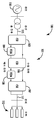
도 1은 본 개시의 실시예들에 따른 전력 시스템을 도시한다.
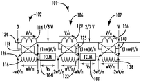
도 2는 본 개시의 실시예들에 따른 예시적인 고장 전류 제한기를 도시한다.
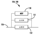
도 3은 본 개시의 실시예들에 따른 도 2의 고장 전류 제한기의 예시적인 고장 전류 제한기 모듈을 도시한다.
도 4는 본 개시의 실시예들에 따른 폐쇄된 단부들을 갖는 도 2의 예시적인 고장 전류 제한기를 도시한다.
도 5는 본 개시의 실시예들에 따른 권선들 사이에 배치되는 다수의 고장 전류 제한기 스위칭 모듈들을 포함하는 예시적인 고장 전류 제한기를 도시한다.
도면들이 반드시 축적이 맞추어져야 하는 것은 아니다. 도면들은 단지 표현들이며, 본 개시의 특정 파라미터들을 표현하도록 의도되지 않는다. 도면들은 본 개시의 예시적인 실시예들을 묘사하도록 의도되며, 따라서 범위를 제한하는 것으로서 간주되지 않아야 한다. 도면들 내에서, 유사한 번호들이 유사한 엘리먼트들을 나타낸다.The accompanying drawings illustrate an exemplary approach of the present disclosure including a practical application of the principles.
Figure 1 illustrates a power system in accordance with embodiments of the present disclosure.
Figure 2 illustrates an exemplary fault current limiter in accordance with embodiments of the present disclosure.
Figure 3 illustrates an exemplary fault current limiter module of the fault current limiter of Figure 2 in accordance with embodiments of the present disclosure.
Figure 4 illustrates an exemplary fault current limiter of Figure 2 with closed ends in accordance with embodiments of the present disclosure.
Figure 5 illustrates an exemplary fault current limiter including a plurality of fault current limiter switching modules disposed between windings in accordance with embodiments of the present disclosure.
The drawings do not necessarily have to be stored. The figures are merely representations and are not intended to represent any particular parameter of the disclosure. The drawings are intended to depict exemplary embodiments of the present disclosure and are not therefore to be construed as limiting the scope. Within the figures, like numbers represent like elements.
이제 이하에서 본 실시예들이, 일부 실시예들이 도시된 첨부된 도면들을 참조하여 더 완전하게 설명될 것이다. 본 개시의 내용이 다수의 상이한 형태들로 구현될 수 있으며, 본원에서 기술되는 실시예들에 한정되는 것으로 해석되지 않아야 한다. 이러한 실시예들은 본 개시가 완전하고 철저해질 수 있도록 제공되며, 본원의 범위를 당업자들에게 완전하게 전달할 것이다. 도면들에서, 유사한 도면번호들이 전체에 걸쳐 유사한 엘리먼트들을 지칭한다.BRIEF DESCRIPTION OF THE DRAWINGS In the following, the present embodiments will be more fully described with reference to the accompanying drawings, in which certain embodiments are shown. The contents of this disclosure may be embodied in many different forms and should not be construed as limited to the embodiments set forth herein. These embodiments are provided so that this disclosure will be thorough and complete, and will fully convey the scope of the invention to those skilled in the art. In the drawings, like numerals refer to like elements throughout.
본원에서 사용될 때, 단수로 언급되고 및 단어 "일" 또는 "하나"가 선행되는 엘리먼트 또는 동작은 달리 표시되는 것을 제외하고는 아마도 복수의 엘리먼트들 또는 동작들을 포함하는 것으로 이해되어야만 한다. 또한, "본 개시의 "일 실시예" 또는 "일부 실시예들"에 대한 언급들은, 언급된 특징들을 또한 통합하는 추가적인 실시예를 포함하는 것으로서 해석될 수 있다. As used herein, an element or an operation referenced in the singular and the word "a" or "one" is to be understood as encompassing a plurality of elements or operations, except as otherwise indicated. It should be further understood that the " one embodiment "or" some embodiments "of the present disclosure may be interpreted as including additional embodiments incorporating the features also mentioned.
본 실시예들은 개선된 고장 전류 보호를 위한 접근 방식들과 관련된다. 더 구체적으로, 다양한 실시예들은 전류 분할 디바이스 내에서 권선들에 걸친 증가된 전압 강하, 및 권선들 사이의 대응하는 증가된 절연에 관한 문제들을 해결한다. 예를 들어, 고장 전류 제한기(fault current limiter; FCL)를 전류 분할 디바이스의 권선들 사이에 산재되는 FCL 스위칭 모듈들을 갖는 부분들로 분할함으로써, 고장 전류 제한기는 권선들 사이에 더 적은 절연을 가지고 만들어질 수 있으며, 따라서 플럭스 및 그에 따른 임피던스를 소거하는 임무를 더 용이하게 만들 수 있다.The embodiments relate to approaches for improved fault current protection. More specifically, various embodiments solve the problems associated with increased voltage drop across the windings in the current splitting device, and corresponding increased insulation between the windings. For example, by dividing the fault current limiter (FCL) into parts with FCL switching modules interspersed between the windings of the current dividing device, the fault current limiter has less insulation between the windings Thus making it easier to eliminate the flux and hence the impedance mismatches.
일부 실시예들에 있어서, 고장 전류 제한기는, 제 1 코어 둘레에 감긴 1차 권선 및 2차 권선을 포함하는 제 1 전류 분할 디바이스, 및 제 2 코어 둘레에 감긴 1차 권선 및 2차 권선을 포함하는 제 2 전류 분할 디바이스를 갖는다. 고장 전류 제한기는, 제 1 전류 분할 디바이스의 2차 권선과 제 2 전류 분할 디바이스의 2차 권선 사이에 전기적으로 직렬로 연결되는 고장 전류 제한기 모듈(예를 들어, 스위칭 모듈)을 더 포함할 수 있다. 고장 전류 제한기는 제 2 전류 분할 디바이스의 2차 권선과 전기적으로 직렬로 연결되는 제 2 고장 전류 제한기 모듈을 더 포함할 수 있다. 고장 전류 제한기를 권선들 사이에 산재된 고장 전류 제한기 모듈들을 갖는 부분들로 분할함으로써, 고장 전류 제한기는 유익하게는 권선들 사이에 더 적은 절연을 가지고 만들어지게 될 수 있다.In some embodiments, the fault current limiter includes a first current splitting device including a primary winding and a secondary winding wound about a first core, and a primary winding and a secondary winding wound around the second core Lt; / RTI > The fault current limiter may further comprise a fault current limiter module (e.g., a switching module) that is electrically connected in series between the secondary of the first current splitting device and the secondary of the second current splitting device have. The fault current limiter may further comprise a second fault current limiter module that is electrically connected in series with the secondary winding of the second current divider device. By dividing the fault current limiter into portions having fault current limiter modules interspersed between the windings, the fault current limiter can advantageously be made with less insulation between the windings.
이제 도 1을 참조하여, 본 개시의 실시예들에 따른 예시적인 전력 시스템이 설명될 것이다. 도시된 바와 같이, 고장 전류 제한기(FCL)(101)를 포함하는 전력 시스템(100)은, 전력을 생성하고 이를 다양한 산업용, 상업용, 및/또는 주거용 전기 부하들에 전달하는 생성, 송신 및 분배 네트워크들을 포함하도록 구현된다. FCL(101)은, 제 1 고장 전류 제한기 모듈(fault current limiter module; FCLM))(104)과 전기적으로 결합되는 제 1 전류 분할 디바이스(current splitting device; CSD)(102), 및 CSD(102)와 전기적으로 결합되는 제 2 전류 분할 디바이스(CSD)(106)를 포함할 수 있다. FCL(101)은, 일부 실시예들에 있어서, 제 3 CSD(107)를 포함할 수 있다. 도시된 바와 같이, 제 2 CSD(106)는 제 1 FCLM(104) 및 제 3 CSD(107)에 더 결합되며, 그리고 제 2 FCLM(108)과 더 결합된다. 일부 실시예들에 있어서, 제 1 및 제 2 CSD들(102, 106)의 각각은, 이하에서 더 상세하게 설명되는 바와 같이 인터리빙된 권선들을 갖는 모듈식 전류 분할 리액터이다. Referring now to Figure 1, an exemplary power system in accordance with embodiments of the present disclosure will be described. As shown, the
추가로 도시된 바와 같이, 전력 시스템(100)은 전도체들(115 및 117)을 통해 AC 전력 소스(101) 및 하나 이상의 전기적 부하들(112) 중간에 전기적으로 직렬로 연결될 수 있다. 당업자는, FCL(101)이 고장 전류 제한이 희망되는 다양한 다른 애플리케이션들 및 전력 시스템 구성들에서 구현될 수 있다는 것을 이해할 것이다. 따라서 도 1에 도시된 특정 전력 시스템(100)은 예로서 도시되며 제한적으로 의도되지 않는다.As further shown, the
제 1, 제 2 및 제 3 CSD들(102, 106, 107)의 각각은 개방 코어 설계를 가질 수 있다. 각기 인터리빙된 권선들을 갖는 전류 분할 디바이스들(102, 106, 및 107)을 포함하는 FCL(101)은 유익하게는 낮은 삽입 임피던스를 제공한다. 일 예로서, 본원에서 설명되는 FCL(101)은, 완전한 부하 전류를 운반할 때, 정상 동작 상태 동안 전체 시스템 전압의 1% 미만인, 임피던스에 걸쳐 강하되는 전압을 야기하는 삽입 임피던스를 가질 수 있다.Each of the first, second and
본원에서 설명되는 FCL(101)은, 예를 들어, 송신, 분배 및 생성 시스템들과 같은 임의의 전기적 시스템에서 고장 전류들을 제한하도록 구현될 수 있다. 추가로, 일부 경우들에 있어서, 인터리빙된 권선들을 갖는 CSD들(102, 106, 107)은 초전도 FCL, 고체 상태 FCL, 고속 스위치 FCL, 또는 일반적으로, 정상 동작 동안 낮은 삽입 임피던스가 의도되는 고장 전류들로부터 시스템을 보호하도록 구성된 임의의 고장 전류 제한 회로 내에 구현될 수 있다. 일부 예들에 있어, FCL(101)은 포화된(saturated) 철 코어들 또는 차폐된 코어들을 통합할 수 있다. 비제한적이고 예시적인 일 예에 있어, 본원에서 설명되는 인터리빙된 권선들을 갖는 제 1 및 제 2 CSD들(102, 106, 107)을 갖는 FCL(101)은, 높은 삽입 임피던스를 갖는 포화된 철 코어 FCL의 삽입 임피던스를 낮추기 위해 제공될 수 있다. 또한, 본원에서 제공되는 다양한 예들이 고 주파수 또는 저 주파수 시스템들에 대하여 FCL 디바이스들 내에서 구현될 수 있다.The FCL 101 described herein may be implemented to limit fault currents in, for example, any electrical system, such as transmission, distribution, and generation systems. Further, in some cases, the
이제 도 1 내지 도 2를 참조하여, FCL(101)이 더 상세하게 설명될 것이다. 도시된 바와 같이, FCL(101)의 제 1 전류 분할 디바이스(102)는, 철 또는 공기 코어와 같은 제 1 코어(118) 둘레에 감긴 1차 권선(114) 및 2차 권선(116)을 포함할 수 있다. 일 실시예에 있어서, 1차 권선(114) 및 2차 권선(116)은, 입력 (라인) 전압을 기준으로 하여 철 코어 둘레에 동심적으로 감길 수 있으며, 접지(earth) 및/또는 다른 CSD 코어들로부터 플로팅(float)되거나 또는 절연된다. 제 2 CSD(106)는 제 2 코어(125) 둘레에 감긴 1차 권선(120) 및 2차 권선(122)을 포함한다. FCL(101)은, 제 1 CSD(102)의 2차 권선(116)과 제 2 CSD(106)의 2차 권선(122) 사이에 전기적으로 직렬로 연결되는 제 1 FCLM(104)을 더 포함한다. 도시된 바와 같이, 제 1 및 제 2 CSD들(102, 106)의 각각의 권선들은 서로 병렬로 배열된다. 추가로, 제 1 CSD(102)의 1차 권선(114)은, 예를 들어, 경로(124)를 따라서 제 2 CSD(106)의 1차 권선(120)과 전기적으로 직렬로 연결되며, 제 1 CSD(102)의 1차 권선(114)은 제 1 FCLM(104)과 전기적으로 병렬로 연결된다. 일부 실시예들에 있어서, 제 1 코어(118) 둘레에 감긴 1차 권선(114) 및 2차 권선(116)은 동일하거나 또는 상이한 수의 턴(turn)들을 갖는다. 유사하게, 제 2 코어(125) 둘레에 감긴 1차 권선(120) 및 2차 권선(122)은 동일하거나 또는 상이한 수의 턴들을 갖는다. Referring now to Figures 1 and 2, the FCL 101 will be described in more detail. As shown, the first
FCL(101)은 제 3 코어(140) 둘레에 감긴 1차 권선(136) 및 2차 권선(138)을 갖는 제 3 CSD(107)를 더 포함할 수 있다. 제 2 FCLM(108)은 제 2 CSD(106)의 2차 권선(122)과 제 3 CSD(107)의 2차 권선(138) 사이에 전기적으로 직렬로 연결된다. 배열된 바와 같이, 제 1 FCLM(104) 및 제 2 FCLM(108)은 경로(126)를 따라 전기적으로 직렬로 연결된다. 또한, 제 2 CSD(106)의 1차 권선(120)은, 예를 들어, 경로(124)를 따라서 제 1 CSD(106)의 1차 권선(114) 및 제 3 CSD(107)의 1차 권선(136)과 전기적으로 직렬로 연결된다. 제 2 CSD(106)의 1차 권선(120)은 또한 제 1 FCLM(104) 및 제 2 FCLM(108)과 전기적으로 병렬로 연결된다. 제 1, 제 2, 및 제 3 CSD들(102, 106, 107)의 권선들의 각각은 정상 상태 동작 동안 최소 임피던스를 나타내고, 2차 권선들이 개방 회로화될(circuited) 때, 예컨대 고장 상태 동안, 고장 전류를 유효하게 제한하기 위하여, 직렬로 1차 권선들로부터 비교적 큰 임피던스를 나타내도록 구성될 수 있다. The
일부 실시예들에 있어서, FCL(101)은 일련의 스위치들, 예컨대 임의의 고속 개방 기술품, 예를 들어, 전압 보호 디바이스 및 전압 제어 디바이스를 갖는 초전도체 기반, 가포화(saturable) 철 코어, 기계적 또는 고체 상태 스위치들을 포함할 수 있다. 예를 들어, 도 3에 도시된 바와 같이, 제 1 및 제 2 FCLM들(104, 108)의 각각은, 각각이 서로 병렬로 배열되는 금속 산화물 바리스터(metal oxide varistor; MOV)(150), 스너버(snubber)(151), 및 고체 상태 스위치(152)를 포함할 수 있다. In some embodiments, the
이제 도 2 및 도 4를 참조하여, FCL(101)의 동작이 더 상세하게 설명될 것이다. 예시적인 실시예에 있어서, 정상 상태 동작 동안, CSD(102)의 1차 권선(114) 및 2차 권선(116)은 정상 상태 전류를 미리 정의된 방식으로 병렬 경로들(124 및 126)을 따라 분배하도록 설정될 수 있다. 예를 들어, 정상 상태 전류의 x%가 경로(124)를 따라 흐르는 경우, 정상 상태 전류의 나머지 (100-x)%가 경로(126)를 따라 흐른다. 일 실시예에 있어서, 전류는, 경로(124)를 따라 50%가 흐르고 경로(126)를 따라 50%가 흐르도록 분배될 수 있다. 다른 실시예에 있어서, 비율은, 40%가 경로(124)를 따라 흐르고 60%가 경로(126)를 따라 흐르도록; 30%가 경로(124)를 따라 흐르고 70%가 경로(126)를 따라 흐르도록, 등으로 설정될 수 있다. Referring now to Figures 2 and 4, the operation of the
고장 전류 상태 동안, 정상 전류보다 더 높은 고장 전류가 1차 권선(114) 및 2차 권선(116) 내로 흐른다. 고장 전류가 미리 정의된 트리거(trigger) 전류를 초과할 때, 2차 권선(116)을 통해 흐르는 전류의 양이 감소된다. 이와 같이, 1차 권선(114) 및 2차 권선(116)을 통해 흐르는 암페어-권선수(amper-turns)의 양이 더 이상 동일하지 않으며, 코어(118) 내의 자기장들이 더 이상 상쇄되지 않을 것이고, 따라서 제 1 CSD(102)의 리액턴스(reactance)를 증가시킨다. 이는 결과적으로 FCL(101)의 삽입 임피던스가 증가되게끔 하며, 따라서 고장 전류를 제한한다. 유사한 결과들이 제 2 CSD(106) 및 제 3 CSD(107)의 각각에 의해 달성될 수 있다. During the fault current state, a higher fault current than the steady current flows into the primary winding 114 and the secondary winding 116. [ When the fault current exceeds a predefined trigger current, the amount of current flowing through the secondary winding 116 is reduced. As such, the amount of amper-turns flowing through the primary winding 114 and the secondary winding 116 is no longer the same and the magnetic fields in the
이해될 바와 같이, 결합된 리액터로서 만들어지는 통상적인 고장 전류 제한기들과 관련된 하나의 단점은 권선-간 전압의 증강이다. 예를 들어, 예시적인 FCL이 2차 전류를 제어하기 위한 75% 제한 및 5:1 트랜스포머 비율을 갖는 33kV 제한기(접지에 대해 19.0kV(19.0kV to earth))를 포함하는 경우, 1차 권선은 접지에 대해 19.0kV를 볼 것이며 제한될 때 14.3kV로 강하될 것이다. 2차 권선이 또한 FCL 스위칭 모듈들이 폐쇄될 때 접지에 대해 19kV를 볼 것이지만, 스위칭 모듈이 개방될 때 71.5kV(14.3kVx5)를 볼 것이다. 리액터들이 접지로부터 개별적으로 절연되고 FCL이 상호 리액터인 경우에, 부하 측 상의 고체 고장(solid fault) 동안의 최대 권선-간 전압은 14.3kV+71kV = 85.8kV일 것이다. 따라서, 적어도 플럭스의 99%가 상쇄되는 85.8kV에 근접하는 절연 레벨을 갖는 인터리빙된 권선을 만드는 것은 상당한 공학적 난제이다.As will be appreciated, one disadvantage associated with conventional fault current limiters made as combined reactors is the enhancement of the inter-turn voltage. For example, if the exemplary FCL includes a 75% limit for controlling the secondary current and a 33 kV limiter (19.0 kV to earth for ground) with a 5: 1 transformer ratio, Will see 19.0 kV for ground and will drop to 14.3 kV when it is limited. The secondary winding will also see 19kV for ground when the FCL switching modules are closed, but will see 71.5kV (14.3kVx5) when the switching module is open. If the reactors are individually isolated from ground and the FCL is a mutual reactor, the maximum winding-to-voltage during a solid fault on the load side will be 14.3kV + 71kV = 85.8kV. Thus, making interleaved windings with an isolation level approaching 85.8 kV at least 99% of the flux is canceled is a significant engineering challenge.
플럭스 상쇄 문제를 일반화하면, 전압 강하 V를 갖는 1차 권선, 및 1차 권선에 대하여 권선수 비율 1:w를 갖는 2차 권선에 대하여, 권선들 사이에서 발생되는 전압은 최대 (1+w)V이다. 2차 권선이 2차 권선에 부착된 2개의 FCLM들을 갖는 경우, 각각의 모듈에 걸친 전압(Vs)은 다음의 방정식을 푸는 것에 의해 계산될 수 있다:Generalizing the flux cancellation problem, for a primary winding with a voltage drop V and a secondary winding with a 1: w ratio for a primary winding, the voltage generated between the windings is maximum (1 + w) V. If the secondary winding has two FCLMs attached to the secondary winding, the voltage across each module (Vs) can be calculated by solving the following equation:
V = -wV + 2Vs. => (1+w)V/2 = Vs.V = -wV + 2Vs. => (1 + w) V / 2 = Vs.
공학적 난제를 해결하기 위하여, 이하에서 더 상세하게 설명되는 바와 같이, 본 개시의 실시예들은 FCL(101)을 다수의 부분들 또는 모듈들, 예컨대, 제 1, 제 2 및 제 3 CSD들(102, 106, 107)로 분할할 수 있으며, 권선들 사이에 산재되는 FCLM들(104 및 108)을 제공할 수 있다. 이는 각각의 CSD가 1차 권선과 2차 권선 사이에 더 적은 절연을 가지고 만들어지는 것을 가능하게 하며, 따라서 플럭스 및 그에 따른 임피던스를 상쇄하는 임무를 더 용이하게 만든다. To solve the engineering challenge, embodiments of the present disclosure may be used to couple
더 구체적으로, 도시된 바와 같이, FCL(101)은 'n개의' 부분들(예를 들어, 'n개의' CSD들)로 분할되며, 각각의 부분은 전압 강하 V를 갖는 1차 권선 및 1차 권선에 대하여 1:w의 권선수 비율을 갖는 2차 권선을 포함한다. 따라서, 권선들 사이에서 발생되는 전압은 최대 (1+w)V/n이다. 예를 들어, 도 4에 도시된 바와 같이, 리액터 장치의 단부들을 폐쇄함으로써, 각각의 FCLM(104, 108)의 전압들이 다음과 같이 계산될 수 있다:More specifically, as shown, the
V = -wV/n + Vs - wV/n + Vs - wV/n => V = -3wV/n + 2VsV = -wV / n + Vs-wV / n + Vs-wV / n => V = -3wV / n + 2Vs
이러한 예에서 n = 3이기 때문에, 전압들이 다음과 같이 계산될 수 있다:In this example, since n = 3, the voltages can be calculated as follows:
V= -wV +2Vs => (1+w)V/2 = Vs.V = -wV + 2Vs = > (1 + w) V / 2 = Vs.
결과적으로, 모든 모듈들에 걸쳐 보여지는 총 전압은 (1+w)V이다. 이러한 경우에 있어서, 리액터를 27개의 세그먼트들로 분할하고, 26개의 스위치들(예를 들어, 각기 적어도 3.3kV 등급)을 설치함으로써, 리액터 세그먼트들 내의 권선-간 전압은 1.65kV가 될 것이며, 이는 FCL(101)에 대한 절연 요구들을 훨씬 더 달성이 가능하게 만들 것이다. As a result, the total voltage across all modules is (1 + w) V. In this case, by dividing the reactor into 27 segments and installing 26 switches (e.g., at least 3.3 kV each), the inter-turn voltage in the reactor segments will be 1.65 kV, Making the isolation requirements for
이제 도 5를 참조하여, 본 발명의 다른 실시예에 따른 FCL(201)이 설명될 것이다. 도시된 바와 같이, 이러한 실시예에 있어서, FCL(201)은 제 1 CSD(202)의 2차 권선(216)과 제 2 CSD(206)의 2차 권선(222) 사이에 전기적으로 직렬로 연결된 다수의 FCLM들(256, 258)을 포함한다. FCL(201)은 제 2 CSD(206)의 2차 권선(222)과 제 3 CSD(207)의 2차 권선(238) 사이에 직렬로 연결된 다수의 FCLM들(260, 262)을 더 포함할 수 있다. 배열된 바와 같이, FCL(201)은 nx개의 세그먼트들로 분할되며, 여기에서 x = FCLM들의 수이다. 따라서, 최대 권선-간 스탠드-오프(stand-off) 전압은 (1+w)xV/n일 것이다. Referring now to FIG. 5, an
이상에서 설명된 실시예들과 유사하게, FCL(201)의 제 1 CSD(202)는 제 1 코어(218) 둘레에 감긴 1차 권선(214) 및 2차 권선(216)을 포함할 수 있다. 제 2 CSD(206)는 제 2 코어(225) 둘레에 감긴 1차 권선(220) 및 2차 권선(222)을 포함한다. FCL(201)의 FCLM들(256 및 258)은, 제 1 CSD(202)의 2차 권선(216)과 제 2 CSD(206)의 2차 권선(222) 사이에 전기적으로 직렬로 연결된다. 도시된 바와 같이, 제 1 CSD(202)의 1차 권선(214)은, 예를 들어, 경로(224)를 따라서 제 2 CSD(206)의 1차 권선(220)과 전기적으로 직렬로 연결되며, 제 1 CSD(202)의 1차 권선(214)은 FCLM들(256 및 258)과 전기적으로 병렬로 연결된다. 일부 실시예들에 있어서, 제 1 코어(218) 둘레에 감긴 1차 권선(214) 및 2차 권선(216)은 동일하거나 또는 상이한 수의 턴들을 가질 수 있다. 유사하게, 제 2 코어(225) 둘레에 감긴 1차 권선(220) 및 2차 권선(222)은 동일하거나 또는 상이한 수의 턴들을 가질 수 있다. Similar to the embodiments described above, the
FCL(201)은 제 3 코어(240) 둘레에 감긴 1차 권선(236) 및 2차 권선(128)을 갖는 제 3 CSD(207)를 더 포함할 수 있다. FCLM들(260, 262)은 제 2 CSD(206)의 2차 권선(222)과 제 3 CSD(207)의 2차 권선(238) 사이에 전기적으로 직렬로 연결된다. 배열되는 바와 같이, FCLM들(256, 258, 260, 및 262)은 경로(226)를 따라 전기적으로 직렬로 연결된다. 또한, 제 2 CSD(206)의 1차 권선(220)은, 예를 들어, 경로(224)를 따라서 제 1 CSD(206)의 1차 권선(214) 및 제 3 CSD(207)의 1차 권선(236)과 전기적으로 직렬로 연결된다. 제 2 CSD(206)의 1차 권선(220) 및 제 3 CSD(207)의 1차 권선(236)이 또한 FCLM들(256, 258, 260, 및 262)과 전기적으로 병렬로 연결된다. 제 1, 제 2, 및 제 3 CSD들(202, 206, 207)의 제 1 및 제 2 권선들의 각각은, 정상 상태 동작 동안 최소 임피던스를 나타내며 고장 전류를 효과적으로 제한하기 위하여 도시된 바와 같이 고장 상태 동안 비교적 큰 임피던스를 나타내도록 구성될 수 있다. The
정리하면, CSD의 권선들 사이의 FCLM들을 설명하는 본원의 다양한 실시예들은, 각각의 CSD의 병렬 권선들 사이의 감소된 절연 양들을 포함하는 제 1 이점, 및 1차 및 2차 권선들에 에너지가 공급될 때 CSD들 내의 1차 및 2차 권선들 사이의 플럭스의 개선된 상쇄를 포함하는 제 2 이점을 제공한다. In summary, the various embodiments of the present disclosure, which describe the FCLMs between the windings of the CSD, include a first advantage comprising reduced amounts of insulation between the parallel windings of each CSD, Lt; RTI ID = 0.0 > CSDs < / RTI >
본 개시는 본원에서 설명된 특정 실시예에 의해 범위가 제한되지 않는다. 오히려, 본원에서 설명된 실시예들에 더하여, 본 개시의 다른 다양한 실시예들 및 이에 대한 수정예들이 이상의 설명 및 첨부된 도면들로부터 당업자들에게 자명해질 것이다. 따라서, 이러한 다른 실시예들 및 수정예들이 본 개시의 범위 내에 속하도록 의도된다. 추가로, 본 개시는 본원에서 특정 목적을 위한 특정 환경에서의 특정 구현예의 맥락에서 설명되었다. 당업자들은 그 유용함이 이에 한정되지 않으며, 본 개시가 임의의 수의 목적들을 위한 임의의 수의 환경들에서 유익하게 구현될 수 있다는 것을 인식할 것이다. 따라서, 이하에서 기술되는 청구항들은 본원에서 설명된 바와 같은 본 개시의 완전한 폭과 사상의 관점에서 해석되어야만 한다.This disclosure is not to be limited in scope by the specific embodiments described herein. Rather, in addition to the embodiments described herein, various other embodiments of the disclosure and modifications thereto will be apparent to those skilled in the art from the foregoing description and accompanying drawings. Accordingly, these other embodiments and modifications are intended to fall within the scope of the present disclosure. Additionally, this disclosure has been described herein in the context of certain embodiments in a particular environment for particular purposes. Those skilled in the art will appreciate that its usefulness is not limited thereto and that the present disclosure may be advantageously implemented in any number of environments for any number of purposes. Accordingly, the claims set forth below should be construed in light of the full breadth and spirit of this disclosure, as set forth herein.
Claims (15)
제 1 코어 둘레에 감긴 1차 권선 및 2차 권선을 포함하는 제 1 전류 분할 디바이스;
제 2 코어 둘레에 감긴 1차 권선 및 2차 권선을 포함하는 제 2 전류 분할 디바이스; 및
상기 제 1 전류 분할 디바이스의 상기 2차 권선과 상기 제 2 전류 분할 디바이스의 상기 2차 권선 사이에 전기적으로 직렬로 연결되는 고장 전류 제한기 모듈을 포함하는, 고장 전류 제한기.
As a fault current limiter,
A first current splitting device including a primary winding and a secondary winding wound around a first core;
A second current splitting device including a primary winding and a secondary winding wound around a second core; And
And a fault current limiter module electrically connected in series between the secondary winding of the first current splitting device and the secondary winding of the second current splitting device.
상기 제 1 전류 분할 디바이스의 상기 1차 권선은 상기 제 2 전류 분할 디바이스의 상기 1차 권선과 전기적으로 직렬로 연결되는, 고장 전류 제한기.
The method according to claim 1,
Wherein the primary winding of the first current splitting device is electrically connected in series with the primary winding of the second current splitting device.
상기 고장 전류 제한기는, 상기 제 1 전류 분할 디바이스의 상기 2차 권선과 상기 제 2 전류 분할 디바이스의 상기 2차 권선 사이에 전기적으로 직렬로 연결되는 다수의 고장 전류 제한기 모듈들을 더 포함하는, 고장 전류 제한기.
The method according to claim 1,
Wherein the fault current limiter further comprises a plurality of fault current limiter modules electrically connected in series between the secondary winding of the first current splitting device and the secondary winding of the second current splitting device, Current limiter.
상기 고장 전류 제한기는,
제 3 코어 둘레에 감긴 1차 권선 및 2차 권선을 포함하는 제 3 전류 분할 디바이스; 및
상기 제 2 전류 분할 디바이스의 상기 2차 권선과 상기 제 3 전류 분할 디바이스의 상기 2차 권선 사이에 전기적으로 직렬로 연결되는 제 2 고장 전류 제한기 모듈을 더 포함하는, 고장 전류 제한기.
The method according to claim 1,
The fault current limiter comprises:
A third current splitting device including a primary winding and a secondary winding wound around a third core; And
And a second fault current limiter module electrically connected in series between the secondary winding of the second current splitting device and the secondary winding of the third current splitting device.
상기 제 1 전류 분할 디바이스의 상기 1차 권선 및 상기 2차 권선은 상이한 수의 턴(turn)들을 가지며, 상기 제 2 전류 분할 디바이스의 상기 1차 권선 및 상기 2차 권선은 상이한 수의 턴들을 갖는, 고장 전류 제한기.
The method according to claim 1,
Wherein the primary winding and the secondary winding of the first current splitting device have a different number of turns and the primary and secondary windings of the second current splitting device have different numbers of turns , Fault current limiter.
전력 소스;
상기 전력 소스에 전기적으로 연결된 부하;
고장 상태 동안 전류의 양을 제한하기 위하여 상기 부하 및 상기 전력 소스에 전기적으로 결합되는 고장 전류 제한기를 포함하며,
상기 고장 전류 제한기는,
제 1 코어 둘레에 감긴 1차 권선 및 2차 권선을 포함하는 제 1 전류 분할 디바이스;
제 2 코어 둘레에 감긴 1차 권선 및 2차 권선을 포함하는 제 2 전류 분할 디바이스; 및
상기 제 1 전류 분할 디바이스의 상기 2차 권선과 상기 제 2 전류 분할 디바이스의 상기 2차 권선 사이에 전기적으로 직렬로 연결되는 고장 전류 제한기 모듈을 포함하는, 전력 시스템.
As a power system,
Power source;
A load electrically coupled to the power source;
And a fault current limiter electrically coupled to the load and the power source to limit an amount of current during a fault condition,
The fault current limiter comprises:
A first current splitting device including a primary winding and a secondary winding wound around a first core;
A second current splitting device including a primary winding and a secondary winding wound around a second core; And
And a fault current limiter module electrically connected in series between the secondary winding of the first current splitting device and the secondary winding of the second current splitting device.
상기 제 1 전류 분할 디바이스의 상기 1차 권선은 상기 제 2 전류 분할 디바이스의 상기 1차 권선과 전기적으로 직렬로 연결되는, 전력 시스템.
The method of claim 6,
Wherein the primary winding of the first current splitting device is electrically connected in series with the primary winding of the second current splitting device.
상기 전력 시스템은, 상기 제 1 전류 분할 디바이스의 상기 2차 권선과 상기 제 2 전류 분할 디바이스의 상기 2차 권선 사이에 전기적으로 직렬로 연결되는 다수의 고장 전류 제한기 모듈들을 더 포함하는, 전력 시스템.
The method of claim 6,
Wherein the power system further comprises a plurality of fault current limiter modules electrically connected in series between the secondary winding of the first current splitting device and the secondary winding of the second current splitting device, .
상기 전력 시스템은,
제 3 코어 둘레에 감긴 1차 권선 및 2차 권선을 포함하는 제 3 전류 분할 디바이스; 및
상기 제 2 전류 분할 디바이스의 상기 2차 권선과 상기 제 3 전류 분할 디바이스의 상기 2차 권선 사이에 전기적으로 직렬로 연결되는 제 2 고장 전류 제한기 모듈을 더 포함하는, 전력 시스템.
The method of claim 6,
The power system includes:
A third current splitting device including a primary winding and a secondary winding wound around a third core; And
Further comprising a second fault current limiter module electrically connected in series between the secondary winding of the second current splitting device and the secondary winding of the third current splitting device.
상기 고장 전류 제한기 모듈 및 상기 제 2 고장 전류 제한기 모듈은 전기적으로 직렬로 연결되는, 전력 시스템.
The method of claim 9,
Wherein the fault current limiter module and the second fault current limiter module are electrically connected in series.
상기 제 2 전류 분할 디바이스의 상기 1차 권선은 상기 제 2 고장 전류 제한기 모듈과 전기적으로 병렬로 연결되는, 전력 시스템.
The method of claim 9,
Wherein the primary winding of the second current splitting device is electrically connected in parallel with the second fail current limiter module.
상기 고장 전류 제한기 모듈은 전압 보호 디바이스, 전압 제어 디바이스, 및 고체 상태 스위치를 포함하며, 상기 전압 보호 디바이스, 상기 전압 제어 디바이스, 및 상기 고체 상태 스위치는 서로 병렬로 배열되는, 전력 시스템.
The method of claim 6,
Wherein the fault current limiter module comprises a voltage protection device, a voltage control device, and a solid state switch, wherein the voltage protection device, the voltage control device, and the solid state switch are arranged in parallel with each other.
상기 제 1 전류 분할 디바이스의 상기 1차 권선 및 상기 2차 권선은 상이한 수의 턴들을 가지며, 상기 제 2 전류 분할 디바이스의 상기 1차 권선 및 상기 2차 권선은 상이한 수의 턴들을 갖는, 전력 시스템.
The method of claim 6,
Wherein the primary and secondary windings of the first current splitting device have a different number of turns and the primary and secondary windings of the second current splitting device have different numbers of turns, .
제 1 코어 둘레에 감긴 1차 권선 및 2차 권선을 포함하는 제 1 전류 분할 디바이스;
제 2 코어 둘레에 감긴 1차 권선 및 2차 권선을 포함하는 제 2 전류 분할 디바이스;
상기 제 1 전류 분할 디바이스의 상기 2차 권선과 상기 제 2 전류 분할 디바이스의 상기 2차 권선 사이에 전기적으로 직렬로 연결되는 제 1 고장 전류 제한기 모듈; 및
상기 제 2 전류 분할 디바이스의 상기 2차 권선과 전기적으로 직렬로 연결되는 제 2 고장 전류 제한기 모듈을 포함하는, 고장 전류 제한기.
As a fault current limiter,
A first current splitting device including a primary winding and a secondary winding wound around a first core;
A second current splitting device including a primary winding and a secondary winding wound around a second core;
A first fault current limiter module electrically connected in series between the secondary winding of the first current splitting device and the secondary winding of the second current splitting device; And
And a second fault current limiter module electrically connected in series with the secondary winding of the second current divider device.
상기 고장 전류 제한기는 제 3 코어 둘레에 감긴 1차 권선 및 2차 권선을 포함하는 제 3 전류 분할 디바이스를 더 포함하며, 상기 제 2 고장 전류 제한기 모듈은 상기 제 2 전류 분할 디바이스의 상기 2차 권선과 상기 제 3 전류 분할 디바이스의 상기 2차 권선 사이에 전기적으로 직렬로 연결되는, 고장 전류 제한기.15. The method of claim 14,
Wherein the fault current limiter further comprises a third current divider device including a primary winding and a secondary winding wound around a third core, the second fault current limiter module being connected to the secondary of the second current divider device And is electrically connected in series between the winding and the secondary winding of the third current splitting device.
Applications Claiming Priority (3)
| Application Number | Priority Date | Filing Date | Title |
|---|---|---|---|
| US15/339,211 | 2016-10-31 | ||
| US15/339,211 US10447031B2 (en) | 2016-10-31 | 2016-10-31 | Fault current limiter with modular mutual reactor |
| PCT/US2017/050899 WO2018080645A1 (en) | 2016-10-31 | 2017-09-11 | Fault current limiter with modular mutual reactor |
Publications (1)
| Publication Number | Publication Date |
|---|---|
| KR20190065450A true KR20190065450A (en) | 2019-06-11 |
Family
ID=62021847
Family Applications (1)
| Application Number | Title | Priority Date | Filing Date |
|---|---|---|---|
| KR1020197014732A KR20190065450A (en) | 2016-10-31 | 2017-09-11 | Fault-current limiter with modular mutual reactors |
Country Status (7)
| Country | Link |
|---|---|
| US (2) | US10447031B2 (en) |
| EP (1) | EP3533124A4 (en) |
| JP (1) | JP6974453B2 (en) |
| KR (1) | KR20190065450A (en) |
| CN (1) | CN109923749B (en) |
| TW (1) | TWI711241B (en) |
| WO (1) | WO2018080645A1 (en) |
Families Citing this family (2)
| Publication number | Priority date | Publication date | Assignee | Title |
|---|---|---|---|---|
| US10447031B2 (en) * | 2016-10-31 | 2019-10-15 | Varian Semiconductor Equipment Associates, Inc. | Fault current limiter with modular mutual reactor |
| KR20200126278A (en) * | 2019-04-29 | 2020-11-06 | 엘에스일렉트릭(주) | Bidirectional Solid State Circuit Breaker |
Family Cites Families (16)
| Publication number | Priority date | Publication date | Assignee | Title |
|---|---|---|---|---|
| JPS6074932A (en) * | 1983-09-29 | 1985-04-27 | 三菱電機株式会社 | Current limiting device |
| AU2001283487A1 (en) | 2000-07-10 | 2002-01-21 | Igc-Superpower, Llc | Fault-current limiter with multi-winding coil |
| US7283339B2 (en) * | 2005-06-01 | 2007-10-16 | Superpower, Inc | Superconducting FCL using a combined inducted magnetic field trigger and shunt coil |
| WO2008125022A1 (en) | 2007-04-17 | 2008-10-23 | Innopower Superconductor Cable Co., Ltd | Core-saturated superconductive fault current limiter and control method of the fault current limiter |
| CN102005749B (en) * | 2010-12-06 | 2013-08-07 | 山东大学 | Current limiting device with flexible switch characteristic and current limiting method |
| US8787999B2 (en) | 2011-04-15 | 2014-07-22 | Varian Semiconductor Equipment Associates, Inc. | Fault current limited system with current splitting device |
| DE102012218260B3 (en) | 2012-10-05 | 2013-12-05 | Bruker Hts Gmbh | Inductive fault current limiter with split secondary coil arrangement |
| CN103078306B (en) * | 2013-01-09 | 2015-01-21 | 中国科学院电工研究所 | Fault current limiter on basis of combined rapid switch-on switch |
| GB201303569D0 (en) | 2013-02-28 | 2013-04-10 | Univ Cardiff | Fault current limiter |
| US9520713B2 (en) * | 2013-08-22 | 2016-12-13 | Varian Semiconductor Equipment Associates, Inc. | Fast switch fault current limiter |
| US9331476B2 (en) * | 2013-08-22 | 2016-05-03 | Varian Semiconductor Equipment Associates, Inc. | Solid state fault current limiter |
| US9306386B2 (en) * | 2013-09-13 | 2016-04-05 | Raytheon Company | Electromagnetic DC pulse power system including integrated fault limiter |
| US9270110B2 (en) | 2013-12-10 | 2016-02-23 | Varian Semiconductor Equipment Associates, Inc. | Fault current limiter with interleaved windings |
| CN104134980B (en) * | 2014-07-18 | 2017-12-12 | 中国科学院电工研究所 | A kind of H bridges superconduction resistance sense type current limiter |
| CN205509513U (en) * | 2016-04-12 | 2016-08-24 | 西安森宝电气工程有限公司 | Based on fast switch type cascade compensation device |
| US10447031B2 (en) * | 2016-10-31 | 2019-10-15 | Varian Semiconductor Equipment Associates, Inc. | Fault current limiter with modular mutual reactor |
-
2016
- 2016-10-31 US US15/339,211 patent/US10447031B2/en active Active
-
2017
- 2017-09-11 KR KR1020197014732A patent/KR20190065450A/en not_active Application Discontinuation
- 2017-09-11 EP EP17863764.1A patent/EP3533124A4/en not_active Withdrawn
- 2017-09-11 JP JP2019520889A patent/JP6974453B2/en active Active
- 2017-09-11 CN CN201780067249.6A patent/CN109923749B/en not_active Expired - Fee Related
- 2017-09-11 WO PCT/US2017/050899 patent/WO2018080645A1/en unknown
- 2017-09-25 TW TW106132828A patent/TWI711241B/en active
-
2019
- 2019-09-09 US US16/564,361 patent/US10847971B2/en active Active
Also Published As
| Publication number | Publication date |
|---|---|
| TW201818627A (en) | 2018-05-16 |
| JP2019533974A (en) | 2019-11-21 |
| TWI711241B (en) | 2020-11-21 |
| US20200006937A1 (en) | 2020-01-02 |
| CN109923749B (en) | 2021-09-28 |
| EP3533124A1 (en) | 2019-09-04 |
| EP3533124A4 (en) | 2020-06-24 |
| CN109923749A (en) | 2019-06-21 |
| JP6974453B2 (en) | 2021-12-01 |
| US20180123338A1 (en) | 2018-05-03 |
| US10847971B2 (en) | 2020-11-24 |
| US10447031B2 (en) | 2019-10-15 |
| WO2018080645A1 (en) | 2018-05-03 |
Similar Documents
| Publication | Publication Date | Title |
|---|---|---|
| KR102127918B1 (en) | Fast switch fault current limiter and current limiter system | |
| RU2741822C2 (en) | Overvoltage limitation system for medium and high voltage | |
| US8018705B2 (en) | Spark gap protection device | |
| US9331476B2 (en) | Solid state fault current limiter | |
| EP2577701B1 (en) | A very fast transient suppressing device | |
| EP3387747A1 (en) | Transformers with multi-turn primary windings for dynamic power flow control | |
| Hassan et al. | Review of ferroresonance in power distribution grids | |
| US10847971B2 (en) | Fault current limiter with modular mutual reactor | |
| AU2014361908B2 (en) | Power system and fault current limiter with interleaved windings | |
| JP2017500840A5 (en) | Fault current limiter with power system and alternating winding | |
| JP2019533974A5 (en) | ||
| WO2022024185A1 (en) | Magnetic saturation type current limiter system and magnetic saturation type current limiter system installation method | |
| US20200219649A1 (en) | Differential Coil, Solenoid Type, High Voltage Series Reactor | |
| KR101039147B1 (en) | Protection apparatus of transformer for insulating paper | |
| CA3058718C (en) | Interleaved secondary windings arrangement for single phase transformers | |
| Rojewski et al. | The Effect of Phase-to-earth Faults on the Operating Conditions of a Separated 110 kV Grid Normally Operated with Effectively Earthed Neutral, and Temporarily Supplied from a Compensated 110 kV Grid | |
| Gaun et al. | Tertiary reactor and switcher design advancements result in improved Grid reliability | |
| UA19276U (en) | Combined protective device based on a transformer and a reactor |
Legal Events
| Date | Code | Title | Description |
|---|---|---|---|
| A201 | Request for examination | ||
| E902 | Notification of reason for refusal | ||
| E601 | Decision to refuse application |