KR20190037274A - Air filter condition detection - Google Patents
Air filter condition detection Download PDFInfo
- Publication number
- KR20190037274A KR20190037274A KR1020197005620A KR20197005620A KR20190037274A KR 20190037274 A KR20190037274 A KR 20190037274A KR 1020197005620 A KR1020197005620 A KR 1020197005620A KR 20197005620 A KR20197005620 A KR 20197005620A KR 20190037274 A KR20190037274 A KR 20190037274A
- Authority
- KR
- South Korea
- Prior art keywords
- filter
- sensor
- pressure
- air
- data
- Prior art date
Links
Images


Classifications
-
- B—PERFORMING OPERATIONS; TRANSPORTING
- B01—PHYSICAL OR CHEMICAL PROCESSES OR APPARATUS IN GENERAL
- B01D—SEPARATION
- B01D46/00—Filters or filtering processes specially modified for separating dispersed particles from gases or vapours
- B01D46/0084—Filters or filtering processes specially modified for separating dispersed particles from gases or vapours provided with safety means
- B01D46/0086—Filter condition indicators
-
- B—PERFORMING OPERATIONS; TRANSPORTING
- B01—PHYSICAL OR CHEMICAL PROCESSES OR APPARATUS IN GENERAL
- B01D—SEPARATION
- B01D46/00—Filters or filtering processes specially modified for separating dispersed particles from gases or vapours
- B01D46/0084—Filters or filtering processes specially modified for separating dispersed particles from gases or vapours provided with safety means
- B01D46/009—Identification of filter type or position thereof, e.g. by transponders or bar codes
-
- B—PERFORMING OPERATIONS; TRANSPORTING
- B01—PHYSICAL OR CHEMICAL PROCESSES OR APPARATUS IN GENERAL
- B01D—SEPARATION
- B01D46/00—Filters or filtering processes specially modified for separating dispersed particles from gases or vapours
- B01D46/10—Particle separators, e.g. dust precipitators, using filter plates, sheets or pads having plane surfaces
-
- B—PERFORMING OPERATIONS; TRANSPORTING
- B01—PHYSICAL OR CHEMICAL PROCESSES OR APPARATUS IN GENERAL
- B01D—SEPARATION
- B01D46/00—Filters or filtering processes specially modified for separating dispersed particles from gases or vapours
- B01D46/42—Auxiliary equipment or operation thereof
-
- B—PERFORMING OPERATIONS; TRANSPORTING
- B01—PHYSICAL OR CHEMICAL PROCESSES OR APPARATUS IN GENERAL
- B01D—SEPARATION
- B01D46/00—Filters or filtering processes specially modified for separating dispersed particles from gases or vapours
- B01D46/42—Auxiliary equipment or operation thereof
- B01D46/429—Means for wireless communication
-
- B—PERFORMING OPERATIONS; TRANSPORTING
- B01—PHYSICAL OR CHEMICAL PROCESSES OR APPARATUS IN GENERAL
- B01D—SEPARATION
- B01D46/00—Filters or filtering processes specially modified for separating dispersed particles from gases or vapours
- B01D46/42—Auxiliary equipment or operation thereof
- B01D46/44—Auxiliary equipment or operation thereof controlling filtration
- B01D46/446—Auxiliary equipment or operation thereof controlling filtration by pressure measuring
-
- B—PERFORMING OPERATIONS; TRANSPORTING
- B01—PHYSICAL OR CHEMICAL PROCESSES OR APPARATUS IN GENERAL
- B01D—SEPARATION
- B01D46/00—Filters or filtering processes specially modified for separating dispersed particles from gases or vapours
- B01D46/52—Particle separators, e.g. dust precipitators, using filters embodying folded corrugated or wound sheet material
- B01D46/521—Particle separators, e.g. dust precipitators, using filters embodying folded corrugated or wound sheet material using folded, pleated material
-
- F—MECHANICAL ENGINEERING; LIGHTING; HEATING; WEAPONS; BLASTING
- F24—HEATING; RANGES; VENTILATING
- F24F—AIR-CONDITIONING; AIR-HUMIDIFICATION; VENTILATION; USE OF AIR CURRENTS FOR SCREENING
- F24F11/00—Control or safety arrangements
- F24F11/30—Control or safety arrangements for purposes related to the operation of the system, e.g. for safety or monitoring
- F24F11/32—Responding to malfunctions or emergencies
- F24F11/39—Monitoring filter performance
-
- G—PHYSICS
- G01—MEASURING; TESTING
- G01L—MEASURING FORCE, STRESS, TORQUE, WORK, MECHANICAL POWER, MECHANICAL EFFICIENCY, OR FLUID PRESSURE
- G01L13/00—Devices or apparatus for measuring differences of two or more fluid pressure values
-
- G—PHYSICS
- G01—MEASURING; TESTING
- G01L—MEASURING FORCE, STRESS, TORQUE, WORK, MECHANICAL POWER, MECHANICAL EFFICIENCY, OR FLUID PRESSURE
- G01L19/00—Details of, or accessories for, apparatus for measuring steady or quasi-steady pressure of a fluent medium insofar as such details or accessories are not special to particular types of pressure gauges
- G01L19/08—Means for indicating or recording, e.g. for remote indication
- G01L19/086—Means for indicating or recording, e.g. for remote indication for remote indication
-
- G—PHYSICS
- G01—MEASURING; TESTING
- G01N—INVESTIGATING OR ANALYSING MATERIALS BY DETERMINING THEIR CHEMICAL OR PHYSICAL PROPERTIES
- G01N15/00—Investigating characteristics of particles; Investigating permeability, pore-volume, or surface-area of porous materials
- G01N15/08—Investigating permeability, pore-volume, or surface area of porous materials
- G01N15/082—Investigating permeability by forcing a fluid through a sample
- G01N15/0826—Investigating permeability by forcing a fluid through a sample and measuring fluid flow rate, i.e. permeation rate or pressure change
-
- H—ELECTRICITY
- H04—ELECTRIC COMMUNICATION TECHNIQUE
- H04W—WIRELESS COMMUNICATION NETWORKS
- H04W4/00—Services specially adapted for wireless communication networks; Facilities therefor
- H04W4/30—Services specially adapted for particular environments, situations or purposes
- H04W4/33—Services specially adapted for particular environments, situations or purposes for indoor environments, e.g. buildings
-
- H—ELECTRICITY
- H04—ELECTRIC COMMUNICATION TECHNIQUE
- H04W—WIRELESS COMMUNICATION NETWORKS
- H04W4/00—Services specially adapted for wireless communication networks; Facilities therefor
- H04W4/30—Services specially adapted for particular environments, situations or purposes
- H04W4/38—Services specially adapted for particular environments, situations or purposes for collecting sensor information
-
- H—ELECTRICITY
- H04—ELECTRIC COMMUNICATION TECHNIQUE
- H04W—WIRELESS COMMUNICATION NETWORKS
- H04W4/00—Services specially adapted for wireless communication networks; Facilities therefor
- H04W4/80—Services using short range communication, e.g. near-field communication [NFC], radio-frequency identification [RFID] or low energy communication
-
- F—MECHANICAL ENGINEERING; LIGHTING; HEATING; WEAPONS; BLASTING
- F24—HEATING; RANGES; VENTILATING
- F24F—AIR-CONDITIONING; AIR-HUMIDIFICATION; VENTILATION; USE OF AIR CURRENTS FOR SCREENING
- F24F2110/00—Control inputs relating to air properties
- F24F2110/40—Pressure, e.g. wind pressure
-
- G—PHYSICS
- G01—MEASURING; TESTING
- G01N—INVESTIGATING OR ANALYSING MATERIALS BY DETERMINING THEIR CHEMICAL OR PHYSICAL PROPERTIES
- G01N15/00—Investigating characteristics of particles; Investigating permeability, pore-volume, or surface-area of porous materials
- G01N15/08—Investigating permeability, pore-volume, or surface area of porous materials
- G01N2015/084—Testing filters
Abstract
공기 필터는 필터 매체, 센서, 및 센서에 결합된 회로부를 포함하며, 회로부는 센서로부터 필터 매체의 상태를 나타내는 데이터를 수신하고 그러한 데이터를 무선으로 전송하도록 구성된다. 데이터는 디스플레이를 구비한 디바이스에 의해 수신되어 필터 매체 상태의 표시를 사용자에게 제시하기 위한 정보를 사용할 수 있다.The air filter includes a filter medium, a sensor, and circuitry coupled to the sensor, wherein the circuitry is configured to receive data indicative of the condition of the filter media from the sensor and to transmit such data wirelessly. The data may be received by a device having a display and use information to present an indication of a filter media state to a user.
Description
공기 필터가 퍼니스 및 독립형 공기 정화기에 포함될 수 있다. 공기가 필터를 통해 흡인되면, 필터는 입자들을 포획하여, 그것들이 덕트를 통해 난방, 냉방, 또는 다른 방식으로 조절되는 환경 공간으로 진행하는 것을 방지한다.Air filters may be included in the furnace and standalone air purifiers. Once the air is drawn through the filter, the filter captures the particles and prevents them from going through the duct to the heating, cooling, or other controlled environment space.
가정용 퍼니스 공기 필터는 시간이 지남에 따라 비효율적이 되거나 또는 막히게 되어, 퍼니스 팬 모터의 마모를 최소화하고, 공기 정화 유효성을 유지하고, 적절한 공기 유동을 유지하기 위하여 교체되어야 한다. 종래의 필터 막힘(obstruction)은 공기 유동에 대한 필터 전후의 압력의 차이로 정의된다. 압력의 차이의 증가는 필터가 더 막히게 되어서 교체가 필요함을 나타낸다.Domestic furnace air filters must become ineffective or clogged over time to minimize wear of the furnace fan motor, to maintain air purification effectiveness, and to maintain adequate air flow. Conventional filter obstruction is defined as the difference in pressure before and after the filter against air flow. An increase in the pressure difference indicates that the filter becomes clogged and needs to be replaced.
공기 필터는 필터 매체, 센서, 및 센서에 결합된 회로부를 포함하며, 회로부는 센서로부터 필터 매체의 상태를 나타내는 데이터를 수신하고 그러한 데이터를 무선으로 전송하도록 구성된다. 데이터는 디스플레이를 구비한 디바이스 또는 시스템에 의해 수신되어 필터 매체 상태의 표시를 사용자에게 제시하기 위한 정보를 사용할 수 있다.The air filter includes a filter medium, a sensor, and circuitry coupled to the sensor, wherein the circuitry is configured to receive data indicative of the condition of the filter media from the sensor and to transmit such data wirelessly. The data may be received by a device or system having a display to use information to present an indication of the filter media state to the user.
도 1은 예시적인 실시예에 따른 일회용 공기 필터를 포함하는 사진이다.
도 2는 예시적인 실시예에 따른 필터 매체에 커플링될 차압 센서의 사진이다.
도 3은 예시적인 실시 형태에 따른 차압 센서를 구비한 필터의 블록도이다.
도 4는 예시적인 실시예에 따른 모바일 디바이스 상에서 실행되는 애플리케이션의 시뮬레이션된 사용자 인터페이스의 예시이다.
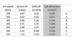
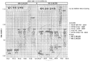
도 5a는 예시적인 실시예에 따른, 송풍기 속력(피트/분), 차압 센서 판독치(밀리바), 덕트 압력, 계산된 압력, 및 도 5b에 도시된 바와 같이 결과들을 그래프에 상관시키는 문자, A, B, 또는 C를 나타내는 표이다.
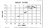
도 5b는 예시적인 실시예에 따른 계산된 압력을 예시하는 그래프이다.
도 6은 예시적인 실시예에 따른 상이한 속력으로 작동하는 송풍기를 이용한 시험에서 획득된 압력들을 비교하는 그래프이다.
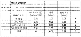
도 7은 예시적인 실시예에 따른 도 5a와 유사한 표이다.
도 8은 예시적인 실시예에 따른 상이한 속력으로 작동하는 송풍기를 이용한 시험에서 획득된 압력들을 비교하는 그래프이다.
도 9는 예시적인 실시예에 따른 상이한 시간 간격에서 압력들을 도시하는 그래프이다.
도 10은 예시적인 실시예에 따른 공기 필터의 막힘을 감지하기 위한 시스템의 블록도이다.
도 11은 예시적인 실시예에 따른 필터 센서와 상호작용하는 모바일 디바이스의 구성 및 사용을 도시하는 블록 흐름도이다.
도 12는 예시적인 실시예에 따른 2개의 압력 센서를 활용하는 예시적인 시스템의 블록도이다.
도 13은 예시적인 실시예에 따른 압력 센서들의 교정을 도시하는 블록 흐름도이다.
도 14는 예시적인 실시예에 따른 예시적인 온도 및 습도 센서에 관한 정보를 제공한다.
도 15는 예시적인 실시예에 따른 스마트 필터를 시험하기 위한 실험용 시스템의 사진이다.
도 16은 예시적인 실시예에 따른 스마트 필터 회로부로부터 스트리밍되는 데이터의 표현들을 제공한다.
도 17은 예시적인 실시예에 따른 일반적인 가정용 퍼니스 덕트 구조물에 설치된 필터의 사진이다.
도 18은 예시적인 실시예에 따른 팬이 처음에 꺼지고, 이어서 켜지고, 다시 꺼질 때 필터에 걸리는 압력의 차이를 도시하는 그래프이다.
도 19는 예시적인 실시예에 따른 스마트 필터를 포함하는 시스템의 동작 동안 전송 및 수집되는 정보를 나타내는 표이다.
도 20은 예시적인 실시예에 따른 퍼니스 또는 팬이 꺼지고, 이어서 켜질 때 단일 하류측 압력 센서로부터의 판독치를 나타내는 그래프이며, 필터는 더러워서 교체가 필요하다고 알려져 있다.
도 21은 예시적인 실시예에 따른 필터의 ID를 제공하고, 필터 매체 상태를 감지하고, 선택적으로 공기질을 감지하기 위한 다양한 옵션들을 구비한 스마트 필터의 블록도 표현이다.
도 22는 예시적인 실시예에 따른 스마트 필터 시스템 내의 다수의 구성요소들 및 대안적인 구성요소들의 블록도 표현이다.
도 23은 예시적인 실시예에 따른 필터 수명을 결정하기 위한 복수의 공급원들로부터의 정보의 구성 및 사용을 도시하는 블록 흐름도이다.
도 24는 예시적인 실시예에 따른, 시간이 지남에 따라 가변 조건 하에서 필터에 걸린 차압을 나타내는 다수의 압력 측정치들을 도시한다.
도 25는 예시적인 실시예에 따른 필터가 삽입되는 덕트 내의 y-방향으로의 진동을 측정하는 가속도계 센서로부터 수집된 데이터를 도시한다.
도 26은 유사하게 예시적인 실시예에 따른, x-방향으로의 진동의 측정치들을 도시한다.
도 27은 유사하게 예시적인 실시예에 따른, z-방향으로의 진동의 측정치들을 도시한다.
도 28은 예시적인 실시예에 따른 y-방향으로의 시간에 대한 가속도계 결과들을 도시한다.
도 29은 예시적인 실시예에 따른 x-방향으로의 시간에 대한 가속도계 결과들을 도시한다.
도 30은 예시적인 실시예에 따른 z-방향으로의 시간에 대한 가속도계 결과들을 도시한다.
도 31은 예시적인 실시예에 따른 회로부 및 방법을 구현하기 위한 컴퓨터 시스템의 블록 개략도이다.1 is a photograph including a disposable air filter according to an exemplary embodiment.
2 is a photograph of a differential pressure sensor to be coupled to a filter medium according to an exemplary embodiment.
3 is a block diagram of a filter with a differential pressure sensor according to an exemplary embodiment.
4 is an illustration of a simulated user interface of an application running on a mobile device according to an exemplary embodiment.
FIG. 5A is a graph illustrating the relationship between the graphs of the blower speed (feet per minute), the differential pressure sensor readings (millibars), the duct pressure, the calculated pressure, and the results graphically as shown in FIG. , B, or C, respectively.
5B is a graph illustrating the calculated pressure in accordance with an exemplary embodiment.
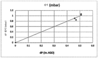
6 is a graph comparing pressures obtained in tests with blowers operating at different speeds according to an exemplary embodiment.
Figure 7 is a table similar to Figure 5a according to an exemplary embodiment.
8 is a graph comparing pressures obtained in tests with blowers operating at different speeds according to an exemplary embodiment.
9 is a graph showing pressures at different time intervals according to an exemplary embodiment.
10 is a block diagram of a system for detecting clogging of an air filter according to an exemplary embodiment.
11 is a block flow diagram illustrating the configuration and use of a mobile device that interacts with a filter sensor in accordance with an exemplary embodiment.
12 is a block diagram of an exemplary system utilizing two pressure sensors in accordance with an exemplary embodiment.
13 is a block flow diagram illustrating calibration of pressure sensors according to an exemplary embodiment.
Figure 14 provides information regarding exemplary temperature and humidity sensors in accordance with an exemplary embodiment.
15 is a photograph of an experimental system for testing a smart filter in accordance with an exemplary embodiment.
Figure 16 provides representations of data streamed from the smart filter circuitry in accordance with an exemplary embodiment.
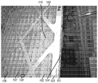
17 is a photograph of a filter installed in a typical household furnace duct structure according to an exemplary embodiment.
18 is a graph showing the difference in pressure applied to the filter when the fan is first turned off, then turned on, and then turned off according to an exemplary embodiment.
19 is a table showing information transmitted and collected during operation of a system including a smart filter in accordance with an exemplary embodiment.
FIG. 20 is a graph showing readings from a single downstream pressure sensor when the furnace or fan according to the exemplary embodiment is turned off and then on; it is known that the filter is dirty and needs to be replaced.
21 is a block diagram representation of a smart filter with various options for providing an ID of a filter according to an exemplary embodiment, sensing filter media status, and optionally sensing air quality.
22 is a block diagram representation of a number of components and alternative components within a smart filter system in accordance with an exemplary embodiment.
23 is a block flow diagram illustrating the organization and use of information from a plurality of sources to determine filter life in accordance with an exemplary embodiment.
24 depicts a number of pressure measurements representative of differential pressure across a filter under variable conditions over time, in accordance with an exemplary embodiment.
Figure 25 shows data collected from an accelerometer sensor that measures vibration in the y-direction within a duct into which a filter according to an exemplary embodiment is inserted.
Fig. 26 similarly shows measurements of vibration in the x-direction, in accordance with an exemplary embodiment.
Figure 27 shows measurements of vibration in the z-direction, similarly in accordance with an exemplary embodiment.
Figure 28 shows accelerometer results for time in the y-direction in accordance with an exemplary embodiment.
29 illustrates accelerometer results for time in the x-direction in accordance with an exemplary embodiment.
30 shows accelerometer results for time in the z-direction in accordance with an exemplary embodiment.
31 is a block schematic diagram of a computer system for implementing circuitry and methods in accordance with an exemplary embodiment.
하기의 설명에서, 설명의 일부를 이루며, 실시될 수 있는 구체적인 실시예들이 예시로서 도시된 첨부 도면을 참조한다. 이들 실시예는 당업자가 본 발명을 실시할 수 있게 하기에 충분히 상세하게 기술되며, 다른 실시예가 이용될 수 있음과 구조적, 로직적 및 전기적 변경이 본 발명의 범주로부터 벗어남이 없이 이루어질 수 있음이 이해될 것이다. 따라서, 예시적인 실시예들의 다음의 설명은 제한적인 의미로 취해지지 않아야 하고, 본 발명의 범주는 첨부된 청구범위에 의해 한정된다.In the following description, reference is made to the accompanying drawings, which form a part hereof, and in which is shown by way of illustration specific embodiments that may be practiced. These embodiments are described in sufficient detail to enable those skilled in the art to practice the invention and that other embodiments may be utilized and that structural, Will be. Accordingly, the following description of exemplary embodiments should not be taken in a limiting sense, and the scope of the present invention is defined by the appended claims.
일 실시예에서 본 명세서에 기재된 기능들 또는 알고리즘들은 소프트웨어로 구현될 수 있다. 소프트웨어는 하나 이상의 비일시적 메모리들 또는 로컬 또는 네트워크 연결된 다른 유형의 하드웨어 기반 저장 디바이스들과 같은 컴퓨터 판독가능 매체 또는 컴퓨터 판독가능 저장 디바이스 상에 저장된 컴퓨터 실행가능 명령어들로 구성될 수 있다. 추가로, 그러한 기능들은, 소프트웨어, 하드웨어, 펌웨어 또는 이들의 임의의 조합일 수 있는 모듈들에 대응한다. 다수의 기능들이, 원하는 대로 하나 이상의 모듈들에서 수행될 수 있고, 기재된 실시예들은 단지 예시일 뿐이다. 소프트웨어는 개인용 컴퓨터, 서버 또는, 기타 컴퓨터 시스템과 같은 컴퓨터 시스템 상에서 동작하는 디지털 신호 프로세서, ASIC, 마이크로프로세서, 또는, 기타 유형의 프로세서 상에서 실행되어, 그러한 컴퓨터 시스템을 특별히 프로그래밍된 기계로 전환시킬 수 있다.In one embodiment, the functions or algorithms described herein may be implemented in software. The software may comprise computer-executable instructions stored on a computer-readable medium or a computer-readable storage device, such as one or more non-volatile memories or other types of hardware-based storage devices, either local or networked. In addition, such functions correspond to modules that may be software, hardware, firmware, or any combination thereof. A number of functions may be performed on one or more modules as desired, and the embodiments described are exemplary only. The software may be executed on a digital signal processor, ASIC, microprocessor, or other type of processor running on a computer system, such as a personal computer, a server or other computer system, to convert such computer system into a specially programmed machine .
실시예들은 공기 필터가 교체되어야 할 시기를 식별하도록 설명된다. 실시예들은 센서들 및 분석들을 활용하여 공기 필터의 교체가 바람직한지 그리고 언제 교체가 바람직한지 결정한다. 교체되어야 할 필터의 표시를 전달하는 데 네트워크 접속이 사용될 수 있다. 표시는, 네트워크를 통해 표시를 수신하는 모바일 디바이스 상에서 실행중인 애플리케이션을 통해 사용자에게 제공될 수 있다. 정보는 예를 들어, 센서와, 필터와 연관된 분석 디바이스 사이의 블루투스 저에너지(BLE) 접속 방향, Wi-Fi 접속, ZigBee, 또는 Zwave와 같은 네트워크 접속에 기초하여 전달될 수 있다. 추가적인 실시예들에서 RFID 기반 접속 또는 기타 접속이 정보를 전달하는 데 사용될 수 있다. 애플리케이션은 자동으로, 또는 애플리케이션에 의해 모바일 디바이스 상에 제공되는 사용자 선택형 옵션에 응답하여 교체 필터의 주문을 가능하게 할 수 있다. 애플리케이션은 또한 필터로부터 바코드, QR 코드, 또는 기타 정보의 판독을 제공하고 그러한 정보를 이용하여 특정 필터들에서만의 센서의 사용을 제어할 수 있다. 정보는 또한 대응하는 필터에 대해 허용된 압력 강하 또는 공기 유동 측정치 파라미터에 대하여 센서들 및/또는 애플리케이션을 구성하는 데 사용될 수 있다.Embodiments are described to identify when the air filter should be replaced. Embodiments utilize sensors and analyzes to determine if replacement of the air filter is desired and when replacement is desired. A network connection may be used to communicate the indication of the filter that needs to be replaced. The indication may be provided to the user via an application running on the mobile device receiving the indication via the network. The information may for example be delivered based on a network connection such as a Bluetooth low energy (BLE) connection direction between the sensor and the analysis device associated with the filter, Wi-Fi connection, ZigBee, or Zwave. In additional embodiments, an RFID-based connection or other connection may be used to convey information. The application may enable ordering of the replacement filter either automatically or in response to a user-selectable option provided on the mobile device by the application. The application can also provide readings of bar code, QR code, or other information from the filter and use that information to control the use of the sensor in specific filters only. The information can also be used to configure sensors and / or applications for allowed pressure drop or air flow measurement parameters for the corresponding filter.
일 실시예에서, 단일 압력 센서, 또는 다수의 상이한 센서들이 필터의 압력 막힘을 식별하는 데 사용될 수 있다. 단일 센서는 필터가 점점 막힘에 따라 모터가 힘을 증가시킴으로써 생성되는 진공 현상을 이용하여 필터와 팬 측 사이의 깨끗한 공기 면 상에 필터 후에 위치설정될 수 있다. 다시 말하면, 팬이 가동되는 동안 압력이 강하하며, 강하는 필터가 더 막히게 됨에 따라 더 커진다. 일 실시예에서, 팬이 꺼져있는 것과 비교하여 팬이 켜져 있는 동안의 2 파스칼 이상의 강하와 같은 임계치가 필터를 교체하기 위한 고객 통지를 트리거하는 데 사용될 수 있다.In one embodiment, a single pressure sensor, or a number of different sensors, can be used to identify the pressure clogging of the filter. A single sensor can be positioned after the filter on the clean air side between the filter and fan side using the vacuum phenomenon created by the motor increasing the force as the filter becomes clogged. In other words, the pressure drops while the fan is running, and the drop increases as the filter becomes more clogged. In one embodiment, a threshold such as a drop of more than 2 pascals while the fan is turned on as compared to when the fan is off may be used to trigger a customer notification to replace the filter.
일 실시예에서, 단일 압력 센서는 압력 판독치를 프로세서 상에서 실행되는 분석 소프트웨어에 제공한다. 프로세서 및 압력 센서는 통합 유닛으로서 형성될 수 있다. 통합 유닛은 또한 네트워킹 능력을 포함할 수 있다. 단일 압력 센서를 사용하는 경우, 센서는 팬 켜짐 및 팬 꺼짐 시의 압력을 관찰함으로써 교정될 수 있다. 이어서 팬 켜짐 시의 압력은 필터의 측면들 사이의 압력 차이를 나타낸다고 가정될 수 있다. 센서 데이터를 활용하여 필터 막힘의 통지를 생성하는 알고리즘들의 여러 예들이 아래에 제공된다.In one embodiment, a single pressure sensor provides the pressure reading to the analysis software running on the processor. The processor and the pressure sensor may be formed as an integrated unit. The integrated unit may also include networking capabilities. If a single pressure sensor is used, the sensor can be calibrated by observing the pressure at the time of fan on and fan off. It can then be assumed that the pressure at the fan turn on indicates the pressure difference between the sides of the filter. Several examples of algorithms that utilize sensor data to generate notifications of filter clogging are provided below.
공기 여과 필터들의 유효성뿐만 아니라 교체할 시기 및 교체 필요 데이터를 전달하는 피드백이 고객들에게 제공될 수 있다. 이전의 개념들은 필터의 상류측 상의 더러운 공기에 의해 막히기 쉽다. 2개의 센서를 유지해야하는 것은 또한 소비자의 센서 비용을 증가시킨다. 알맞은 센서를 소비자들에게 제공하여 그들의 가정용 퍼니스 필터의 적절한 서비스를 통해 그들이 그들의 집에서 높은 공기질 표준을 유지하도록 도울 수 있다.Feedback can be provided to the customers conveying the timing of replacement and replacement data as well as the effectiveness of the air filtration filters. Previous concepts are prone to clogging by dirty air on the upstream side of the filter. The maintenance of two sensors also increases the consumer's sensor cost. By providing appropriate sensors to consumers, the appropriate service of their household furnace filters can help them maintain high air quality standards in their homes.
추가적인 실시예에서, 차압 센서는 필터 매체의 양면 상에 2개의 개구부를 이용하여 필터 매체에 커플링되어 각 면 상의 압력을 차압 감지 요소, 예컨대 커패시터 플레이트 또는 압력의 차이에 응답하여 휘는 압전 소자에 전달할 수 있다. 감지 요소는 한 면 상에 제1 개구부를 이용하여 위치될 수 있고, 제2 개구부를 갖는 튜브가 매체를 통해 매체의 다른 면으로 연장된다. 개구부들은 차압 감지 요소의 양 면 상에 배치된다.In a further embodiment, the differential pressure sensor is coupled to the filter media using two openings on both sides of the filter media to deliver pressure on each surface to a differential pressure sensing element, e.g., a capacitor plate or a piezoelectric element bending in response to a difference in pressure . The sensing element can be positioned using the first opening on one side and the tube having the second opening extends through the medium to the other side of the medium. The openings are disposed on both sides of the differential pressure sensing element.
추가적인 실시예들에서, 압력 이외의 파라미터들이 측정 또는 감지되고, 필터를 교체할 시기를 나타내는 필터 상태와 상관될 수 있다. 이러한 파라미터들은 예를 들어, 팬 모터 상의 부하, 공기속력, 난기류, 미립자, 광학 투명도, 진동, 열전 센서, 구부러짐을 나타내는 변형 게이지, 및 다른 것들을 포함한다. 또 추가적인 실시예들에서, 하나 이상의 센서들로부터의 데이터는 분석 소프트웨어에 의해 융합 또는 다른 방식으로 조합되어 필터 교체를 위한 표시를 생성할 수 있다.In further embodiments, parameters other than pressure may be measured or sensed and correlated with a filter state indicating when to replace the filter. These parameters include, for example, loads on fan motors, air speeds, turbulence, particulates, optical transparency, vibrations, thermoelectric sensors, strain gages representing bending, and others. In yet further embodiments, data from one or more sensors may be fused or otherwise combined by analysis software to produce an indication for filter replacement.
일부 실시예들에서, 센서 및/또는 통합 센서 유닛은 필터 매체에 부착 또는 통합되거나, 또는 필터 매체의 프레임에 부착될 수 있다. 프레임은 영구적인 재충전형 플라스틱 필터 프레임일 수 있다. 일부 실시예들에서, 유닛은 필터 매체 또는 필터의 프레임에 부착되고, 유닛을 분리 및 유닛을 교체 필터, 필터 프레임, 또는 필터 매체에 부착함으로써 재사용될 수 있다. 유닛은 또한 교체형 필터 매체를 갖는 필터의 프레임에 부착될 수 있다.In some embodiments, the sensor and / or the integrated sensor unit may be attached to or integrated with the filter media, or attached to the frame of the filter media. The frame may be a permanent rechargeable plastic filter frame. In some embodiments, the unit may be reused by attaching it to a frame of a filter media or filter, separating the unit and attaching the unit to a replacement filter, filter frame, or filter media. The unit can also be attached to a frame of a filter having an interchangeable filter media.
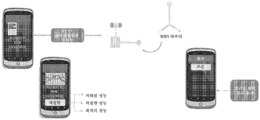
도 1은 일회용 공기 필터(100)를 포함하는 사진이다. 필터(100)는 일반적으로 직사각형 형상을 가질 수 있다(이는 정사각형 형상을 포함함). 일회용 필터(100)는 상류면(101)(먼 쪽을 향하여 보이지 않음) 및 하류면(102)을 포함할 수 있고, 선택적인 주연 프레임(103)에 의해 둘러싸인 필터 매체(107)를 포함할 수 있다. 필터 매체(107)는 필터 매체를 프레임으로부터 분리하고, 필터 매체를 새로운 또는 재조절된 필터 매체로 교체함으로써 교체가능할 수 있다. 추가적인 실시예들에서, 필터 매체는 공기 유동을 겪을 때 공기를 여과하기 위한 효과적인 형상을 유지하기에 충분한 구조적 완전성을 갖도록 형성되는 경우 프레임 없이 자가-지지할 수 있다. 다양한 실시예들에서, 필터 매체(107)는 용이하게 식별가능한 주름들(108)을 나타내도록 주름 형성되거나, 또는, 주름 형성되지 않을 수 있다. 일 실시예에서, 압력 센서와 같은 센서(110)는 필터에 의해 지지된다. 센서(110)는 필터 매체 상태를 나타내는 센서 판독치를 처리하고 전달하기 위한 전자장치들을 포함할 수 있다. 센서는 도 1의 110에 도시된 바와 같은 행잉 구조(hanging structure)에 의해 지지되거나 또는 필터 매체 또는 프레임에 직접 부착될 수 있다.1 is a photograph including the
주연 프레임(103)은 종종, 프레임 형성된 필터의 말단 에지들을 한정하는 측벽(예를 들어, 상부, 저부, 좌측 및 우측 측벽)(104)들을 포함할 수 있다. 프레임(103)은 임의의 적합한 재료(들), 예를 들어 다양한 측벽을 제공하도록 절첩될 수 있는 보드지(paperboard) 또는 판지(cardboard)로 제조될 수 있다. 일부 실시예들에서, 프레임(103)은 사출성형되는 플라스틱 재료로 제조될 수 있다. 일부 실시예들에서, 필터(100)의 적어도 하류면(102)은 적어도 부분적으로 (임의의 방향으로) 필터 매체(107)를 가로질러 연장되는 지지 부재를 포함할 수 있다. 그러한 부재는 특히 필터 매체의 하류측에서 추가적인 지지를 제공할 수 있고, (특히 주름 형성된 필터 매체의 경우에) 그러한 부재는 실내 공기 정화기의 작동 동안에 공기 압력에 응답하여 필터 매체의 변형을 최소화하거나 변형의 일관성을 보장하는 것을 도울 수 있다. 일부 실시예에서, 그러한 부재들은 그들의 말단 단부들에서 프레임(103)에 연결될 수 있는 보드지의 스트립(strip)들일 수 있다. 다른 실시예들에서 그러한 부재들은 접착 스트랜드들의 가닥들일 수 있다. 필터 매체가 주름 형성된 경우, 임의의 그러한 접착 스트랜드는 필터 매체가 주름 형성되기 전후에 침착될 수 있다.The
다양한 주름형성 옵션들을 갖는 많은 상이한 유형들의 필터 양식들이 사용될 수 있다. 예를 들어, 잔주름 설계는 주름 끝에 부착된 와이어를 필터의 한면 또는 양면에서 사용할 수 있다. 미세 주름 설계는 필터 매체의 한면에 와이어를 사용할 수 있는데, 와이어는 매체의 주름을 따라 이어지며 주름 형상을 유지한다. 평면 패널 필터 매체는 와이어 및/또는 폴리올레핀 망을 사용할 수 있다. 일부 필터 설계는 폴리올레핀 스트랜드들 대 접착 스트랜드들을 사용하여 주름 간격을 유지할 수 있다.Many different types of filter styles with various wrinkle forming options can be used. For example, a fine wrinkle design can use a wire attached to the pleat end on one or both sides of the filter. The fine pleated design can use a wire on one side of the filter media, the wire continuing along the corrugations of the media and retaining the corrugated shape. The flat panel filter media may use wires and / or polyolefin meshes. Some filter designs can use polyolefin strands versus adhesive strands to maintain wrinkle spacing.
일회용 공기 필터(100)의 (주름 형성되었든 안되었든 간에) 필터 매체(107)는 이동하는 공기를 여과할 수 있는 임의의 구성으로 거의 임의의 재료로 구성될 수 있다. 그러한 매체는 섬유상 재료(예를 들어, 부직 웨브(web), 유리섬유 웨브 등); 필터 매체 및/또는 흡착(sorbent) 재료가 로딩된(loaded) 벌집형 구조체 등을 포함할 수 있지만, 이로 한정되지 않는다. 특정 실시예에서, 필터 매체는 일렉트릿(electret) 재료를 형성하기 위해 전기적으로 또는 정전기적으로 대전될 수 있는 적어도 일부 재료를 포함하는 적어도 하나의 층을 포함할 수 있다. 특정 실시예에서, 필터 매체는 일렉트릿 재료를 포함하는 적어도 하나의 층 및 흡착 재료를 포함하는 적어도 하나의 층을 포함하는 다층 매체일 수 있다. 일부 실시예에서, 필터 매체(107)는 HEPA 여과가 가능한 적어도 하나의 층을 포함할 수 있다. 정전기적으로 대전된 매체는 미립자 포획을 향상시킬 수 있다. 전기적으로 대전된 매체는 전류 및 접지 와이어를 가지며 전형적으로 세척가능한 정전 집진기에 사용될 수 있다.The filter media 107 (whether pleated or not) of the
필터 매체(107)의 적어도 하나의 층이 흡착 기능을 나타내는 것이라면, 임의의 편리한 물리적 형태의 임의의 적합한 흡착제(들)가 그러한 층에 포함될 수 있다. 특정 실시예들에서, 이러한 흡착제는 포름알데히드의 포획이 가능할 수 있다(포름알데히드는 전형적인 탄소 필터에 의해 포획될 수 없는 매우 가벼운 기체임). 많은 탄소 필터들이 요소(urea), 음식 냄새 등과 같은 훨씬 더 무거운 기체들을 포획한다. 이러한 필터들은 활성탄을 사용한다. 포름알데히드 및 톨루엔 기체를 포획하기 위하여, 처리된(종종 산 처리된) 탄소가 사용될 수 있다. 일부 실시예에서, 흡착제는 적어도 일부의 활성탄을 포함한다. 필요하다면, 활성탄은 그의 포름알데히드 포획 능력을 향상시키도록 처리될 수 있다. 적합한 처리는, 예를 들어 활성탄에 적어도 일부의 아민 작용기 및/또는 적어도 일부의 망간산염 작용기 및/또는 적어도 일부의 요오드화물 작용기를 제공할 수 있다. 적합할 수 있는 처리된 활성탄의 특정 예는, 예를 들어 과망간산칼륨, 요소, 요소/인산, 및/또는 요오드화칼륨으로 처리된 것들을 포함한다. 예를 들어 포름알데히드를 제거하기에 잠재적으로 적합할 수 있는 다른 흡착제는, 예를 들어 처리된 제올라이트 및 처리된 활성 알루미나를 포함한다. 그러한 물질은, 필요한 경우, 예를 들어 처리된 활성탄과 함께 포함될 수 있다.Any suitable adsorbent (s) of any convenient physical form may be included in such a layer, provided that at least one layer of
하나 이상의 흡착제들이 임의의 유용한 형태로 제공될 수 있다; 예를 들어 입자들, 예컨대, 파우더, 비드, 플레이크, 위스커, 과립 또는 덩어리들 일 수 있수 있다. 흡착제 입자 크기는 원하는 대로 변할 수 있다. 흡착제 입자는 임의의 원하는 방식으로 필터 매체(107)의 층 내에 또는 그 상에 혼입될 수 있다. 예를 들어, 다양한 실시예에서, 흡착제 입자는 필터 매체(107)의 층의 섬유와 물리적으로 얽히거나, 그러한 섬유에 접착 접합될 수 있거나, 두 메커니즘의 일부 조합이 사용될 수 있다.One or more adsorbents may be provided in any useful form; For example, be particles, such as powders, beads, flakes, whiskers, granules or lumps. The adsorbent particle size can vary as desired. The adsorbent particles can be incorporated into or onto the layer of
일 실시예에서, 일회용 공기 필터(100)는 적어도 하나의 RFID(radiofrequency identification) 태그(120)를 포함할 수 있다. 일부 실시예에서, RFID 태그(120)는 공기 필터(100)의 주연 프레임(103)의 임의의 부분에 장착될 수 있다. 예를 들어, RFID 태그(120)는 프레임의 측벽의 내부 주 표면에 또는 프레임의 상류 또는 하류 플랜지의 외부 또는 내부(즉, 보이는 또는 보이지 않는) 주 표면에 장착될 수 있다. 일부 실시예에서, RFID 태그(120)는 일회용 공기 필터(100)의 주연 프레임(103)의 측벽(104)의 외향 주 표면에 장착(예를 들어 부착, 예를 들어 접착 부착)된다. RFID 태그(120)는 임의의 적합한 RFID 태그일 수 있다. 많은 실시예에서, RFID 태그(120)는 수동(passive) 태그일 수 있는데, 이는 어떠한 종류의 전원도 포함하지 않고, RFID 판독기에 의해 태그에 충돌되는 전자기 에너지에 의해서만 급전된다는 것을 의미한다. 일부 실시예에서, RFID 태그(120)는 그 범위가 특히 제한되지 않는 (예를 들어, 높은, 중간 또는 낮은 주파수에서 작동하는) 종래의 RFID 태그일 수 있다. 특정 실시예에서, RFID 태그(120)는 수(예를 들어, 10 이하) 센티미터의 범위에 걸쳐서만 (예를 들어, 13.56 ㎒에서) 작동하는 특정 유형의 RFID 태그인 것으로 당업자에 의해 인식될 소위 근거리 통신(Near Field Communication, NFC) 태그일 수 있다. 일부 실시예들에서 RFID 태그(120)는 판독가능(전용) 태그이고; 다른 실시예들에서 판독가능/기록가능 태그일 수 있으며, 이는 본 명세서에 후에 논의되는 바와 같다. 일부 실시예에서, RFID 태그(120)에는 접착 배킹(backing)이 편리하게 제공될 수 있어, RFID 태그(120)가 필터(100)의 프레임의 측벽(104)의 표면 상에 신속하고 용이하게 설치될 수 있도록 한다.In one embodiment, the
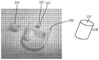
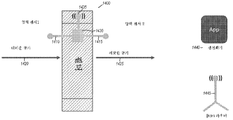
일 실시예에서, 도 2에 나타난 바와 같이, 단일 차압 센서가 사용되고 소형 플라스틱 하우징(200) 내에 봉입될 수 있다. 하우징(200)은 차압을 측정하기 위한 하나 이상의 센서들, 프로세싱 전자장치들 및 블루투스 저에너지 통신 전자장치들을 포함할 수 있다. 압력 센서(들)는 필터의 성능 및 교체되어야 할 시기(즉, 필터 수명의 종료)를 결정하기 위하여 필터의 압력 강하를 측정한다.In one embodiment, as shown in FIG. 2, a single differential pressure sensor may be used and enclosed within the small
일 실시예에서, 하우징(200)은 필터의 팬 측으로부터 필터 재료를 파고들어가서 필터의 여과될 공기를 수용하는 측면에 제1 개구부(212)를 제공하도록 구성된 튜브(210)를 포함한다. 일 실시예에서, 튜브(210)는 필터 매체를 천공하는 데 사용되는 작고 예리한 포트로 형성될 수 있다. 캡 또는 잠금 너트(215)가 튜브 위에 끼워지고 스탭 핏, 마찰 핏, 스크류, 또는 다른 방식으로 하우징을 제위치에서 필터에 유지하면서, 제1 개구부를 통해 하우징(200) 내의 차압 센서의 일 측면으로 압력을 전달할 수 있다.In one embodiment, the
일부 실시예들에서, 필터 매체의 교체를 허용하는 필터 프레임의 경우에, 센서 또는 센서들을 구비한 하우징(200)은 잠금 너트(215)를 제거하고, 필터로부터 하우징(200)의 나머지 부분을 제거하고, 새로운 필터 또는 필터 매체 상에 설치를 반복함으로써 새로운 필터 또는 필터 매체 상에서 재사용될 수 있다. 센서 또는 센서들을 구비한 하우징은 필터 프레임 상에 설치될 수 있고 선택적으로 재사용될 수 있다.In some embodiments, in the case of a filter frame that permits replacement of the filter media, the
제2 개구부는, 도시되지 않았지만, 하우징(200)의 다른 측면 상에 위치설정되어 차압 센서가 제1 개구부와 제2 개구부 사이의 압력 차이를 측정하도록 필터 재료의 팬 측으로부터 차압 센서로 압력을 전달하게 한다.Although not shown, the second opening is positioned on the other side of the
프로세싱 전자장치들(이 경우에 센서 IC에 내장됨)은 압력 측정치들을 블루투스 통신 전자장치를 위한 전기 입력 신호(이 경우에 디지털)로 변환한다. 추가적인 실시예들에서, 프로세싱 전자장치들은 시설 또는 가정에서 (여과 전후) 공기질 측정치들, 필터 동작 시간, 습도 등을 제공하는 기타 포함된 센서들로부터의 신호들을 처리하도록 확장될 수 있다Processing electronics (in this case, embedded in the sensor IC) converts the pressure measurements to an electrical input signal (in this case, digital) for the Bluetooth communication electronics. In further embodiments, the processing electronics may be extended to process signals from other contained sensors that provide air quality measurements, filter operating time, humidity, etc., at the facility or home (before and after filtration)
블루투스 통신 전자장치들은 센서 정보를 사용자의 블루투스 디바이스(즉, 스마트폰, 태블릿 등)에 전송하여 사용자가 디바이스 상에서 실행되는 하나 이상의 애플리케이션들을 통해 필터의 성능을 모니터하고 필터를 교체할 시기를 알 수 있도록 한다. 모니터하는 것 뿐만 아니라, 애플리케이션(들)은 필터를 교체할 때가 되면 사용자에게 통지하도록 구성될 수 있다. 센서는 코인 셀 배터리에 의한 동력식일 수 있다. 이러한 코인 셀 배터리는 고객에 의해 용이하게 교체가능할 것이다. 다른 유형들의 배터리들, 예컨대, 연료 전지 및 재충전가능 배터리가 추가적인 실시예들에서 사용될 수 있다. 배터리 전압 레벨은 디스플레이될 수 있고, 배터리 낮음 경고가 사용자에게 제공되어 사용자가 배터리를 교체하도록 통지할 수 있다.Bluetooth communication electronics send sensor information to a user ' s Bluetooth device (i. E., Smartphone, tablet, etc.) so that the user can monitor the performance of the filter through one or more applications running on the device and know when to replace the filter do. In addition to monitoring, the application (s) may be configured to notify the user when it is time to replace the filter. The sensor may be powered by a coin cell battery. Such a coin cell battery will be easily replaceable by the customer. Other types of batteries, such as fuel cells and rechargeable batteries, may be used in additional embodiments. The battery voltage level may be displayed and a low battery warning may be provided to the user to notify the user to replace the battery.
능동 공기 퍼니스 필터 센서(300)의 블록도가 도 3에 도시된다. 센서 막힘을 방지하기 위하여, 작은 기계적 먼지 캡(305)이 센서 너트(215) 상에 성형될 수 있다. 먼지 캡(305)은 먼지가 센서 포트를 막지 못하게 할 것이다. 센서(300)는 하류 개구부(310)를 포함할 수 있는데, 이는 상류 개구부(212)와 조합하여 차동 센서(315)에 걸친 차동 압력을 제공하며, 이는 일 실시예에서 백 투 백(back to back) 절대 압력 센서들, 또는 정전용량성 플레이트에 걸친 압력의 차이에 응답하여 구부러져서, 플레이트를 포함하는 회로의 커패시턴스를 변화시키는 정전용량성 플레이트를 포함할 수 있다. 프로세서(320)는 센서(315)로부터 감지된 압력 데이터를 수신하고 분석을 수행하여 필터의 상태를 결정하고, 그러한 상태를 나타내는 경고들을 생성하도록 프로그래밍될 수 있다. 블루투스 통신 회로와 같은 무선 회로부(325)는 무선 네트워크 접속을 통해 통신하도록 프로세서(320)에 의해 사용될 수 있다. 배터리(330)는 프로세서, 센서, 및 회로부에 전력을 공급하도록 사용될 수 있다. 또한 무선 신호들의 전송 및 수신을 위해 통신 회로부(325)에 안테나(335)가 커플링된다.A block diagram of the active air
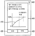
도 4는 모바일 디바이스(400) 상에서 실행되는 애플리케이션의 시뮬레이션된, 그래픽 사용자 인터페이스의 예시이다. 사용자 인터페이스는 다양한 실시예들에서 모니터되고 있는 필터의 상태의 표시를 제공한다. 애플리케이션은 센서(300)로부터 필터의 상태를 나타내는 통신을 수신하고, 410에 표시된 사용자 인터페이스를 통해 정보를 사용자에게 제공한다. 사용자 인터페이스는 필터 성능을 도시하는 그래프(415) 또는 기타 도식, 예컨대, 필터의 차단 백분율, 필터의 사용 백분율, 및 필터의 교체 예상 시간을 나타내는 선을 포함할 수 있다. 사용자에게 옵션들, 예컨대 설정(420) 및 수락(425)이 제공될 수 있다. 옵션들은 선택된 잔여 유효 수명에 대응하는 시간에, 또는 필터 성능이 선택되거나 또는 결정 임계치를 넘어 변질되었다는 결정 시 즉시 교체 필터를 자동으로 주문하기 위한 옵션을 포함할 수 있다. 애플리케이션은 위에서 기재된 바와 같이 필터와 연관된 ID로부터 교체 필터 부품 정보를 RFID 또는 NFC 판독기를 통해, 또는 필터 상의 바코드 또는 QR 코드를 스캐닝함으로써도 획득할 수 있다. 대안적으로, 필터와 연관된 ID는 필터 센서로부터 직접 또는 간접적으로 애플리케이션을 실행하는 디바이스에 블루투스 또는 기타 무선 통신 프로토콜을 통해 전달될 수 있다.Figure 4 is an illustration of a simulated, graphical user interface of an application running on a
필터 센서가 퍼니스 시스템에 설치되면 필터 센서를 교정하는 데 사용될 수 있는 다양한 방법들이 있다. 각각의 교정 방법의 장점 및 단점을 결정하기 위한 시험이 수행될 수 있다.When the filter sensor is installed in the furnace system, there are various methods that can be used to calibrate the filter sensor. A test may be performed to determine the advantages and disadvantages of each calibration method.
필터 센서 교정 방법 #1:Filter Sensor Calibration Method # 1:
1. 필터 센서를 필터 내에 설치함One. Filter sensor installed inside the filter
2. 필터를 퍼니스 시스템 안에 설치함2. The filter is installed in the furnace system.
3. 디바이스 애플리케이션을 시작함3. Launched device application
4. "교정" 버튼을 눌러 차압=0으로 설정함4. Press "Calibration" button to set differential pressure = 0
5. 퍼니스를 가동함5. Activate the furnace
6. "데이터 취합"을 눌러 차압 판독치를 취함6. Press "Data Collection" to take differential pressure reading
일부 실시예들에서, 필터를 식별하기 위하여 가시적 코드를 스캔하거나 또는 RFID, NFC, 또는 기타 무선 방법을 이용하여 필터로부터 정보를 획득하는 데 모바일 디바이스 애플리케이션이 사용될 수 있다. 일부 실시예들에서, 필터를 식별하는 데 필요한 정보는 센서 상에 저장되고, (직접 또는 간접적으로) 모바일 디바이스에 전송될 수 있다. 필터의 식별은 적절한 설정들을 위한 표를 검사하여 사용자에게 필터가 교체되어야 한다고 통지할지 여부를 결정하는 데 사용될 수 있다. 필터 식별이 적절하지 않은 경우, 앱은 필터와 함께 작동하지 않도록 설계될 수 있다. 예를 들어, 애플리케이션은 이미 필터 수명의 종료를 나타낸 센서 상의 리셋을 방지하도록 구성될 수 있다. 애플리케이션은 메모리에 센서 어드레스 및 필터 상태를 저장 또는 그에 액세스할 수 있고, 사용자가 제1 필터로부터 분리되어 제2 필터에 커플링된 센서와 페어링하지 못하게 할 수 있다.In some embodiments, a mobile device application may be used to scan the visible code to identify the filter, or to obtain information from the filter using RFID, NFC, or other wireless methods. In some embodiments, the information needed to identify the filter may be stored on the sensor and transmitted (directly or indirectly) to the mobile device. The identification of the filter can be used to determine whether to notify the user that the filter should be replaced by checking the table for the appropriate settings. If the filter identification is not appropriate, the app may be designed to not work with the filter. For example, the application may be configured to prevent reset on the sensor that already indicates the end of the filter life. The application may store or access the sensor address and filter state in memory and may prevent the user from pairing with the sensor coupled to the second filter separated from the first filter.
필터 센서 교정 방법 #2:Filter Sensor Calibration Method # 2:
1. 필터 센서를 필터 내에 설치함One. Filter sensor installed inside the filter
2. 필터를 퍼니스 시스템 안에 설치함2. The filter is installed in the furnace system.
3. 퍼니스를 가동함3. Activate the furnace
4. 모바일 디바이스 애플리케이션을 시작함4. Launched mobile device application
5. "교정" 버튼을 눌러 차압=0으로 설정함5. Press "Calibration" button to set differential pressure = 0
6. "데이터 취합"을 눌러 차압 판독치를 취함6. Press "Data Collection" to take differential pressure reading
압력 감지 유닛의 성능 및 동작을 확인하기 위하여, 1) 실험실 규모 HVAC 시스템 및 2) 실제 가정용 퍼니스 상의 감지 유닛을 이용하여 2번의 실험이 완수되었다. 감지 유닛은 우선 송풍기 속력을 가변하고, 공기 유동률을 측정하고, 압력 트랜스듀서를 이용하여 필터에 걸친 압력 강하를 측정하는 능력을 갖는 실험실 규모 HVAC 시스템에 배치되었다. 송풍기 속력을 제어하는 능력을 이용하여, 이 시험은 광범위한 공기 유동 속력을 이용하여 실행되어 소정 범위의 센서 응답을 제공하였다.To verify the performance and operation of the pressure sensing unit, two experiments were accomplished using a laboratory scale HVAC system and a sensing unit on a real household furnace. The sensing unit was initially deployed in a laboratory scale HVAC system with the ability to vary the blower speed, measure the air flow rate, and measure the pressure drop across the filter using a pressure transducer. Using the ability to control the blower speed, this test was performed using a wide range of air flow rates to provide a range of sensor responses.
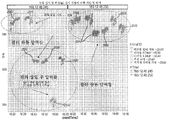
센서는 필터의 중앙 부근에 장착되었고, 이어서 필터 홀더 내에 설치되고, 실험실 규모 HVAC 시스템 내에 설치되었다. 도 5a는 송풍기 속력(피트/분), 차압 센서 판독치(밀리바), 덕트 압력, 계산된 압력, 및 계산된 압력을 예시하는 도 5b에 도시된 바와 같이 결과들을 그래프에 상관시키는 문자, A, B, 또는 C를 나타내는 표이다. 송풍기 속력은 필터를 통하는 300 fpm(전형적인 시험 속도)과 동등한 유동률을 달성하도록 설정되었다. 시험을 수 분 동안 진행하여 정상 상태 조건에서 압력 강하 데이터를 생성하도록 하였다. 이어서 송풍기 속력은 400 fpm 및 500 fpm으로 증가되어 다시 이러한 더 높은 공기 유동 속도에서 센서 응답을 측정하였다. 각각의 시험 속도에서, 압력 트랜스듀서로부터 압력 강하가 기록되었다. 이어서 기록된 압력 강하를 센서 압력 강하와 비교하여 이러한 응답들에 대한 상관관계를 확립하였다.The sensor was mounted near the center of the filter, then in the filter holder, and installed in a laboratory scale HVAC system. 5A is a graph showing the results of the graphs correlating the graphs to the graphs A, B, and C as shown in FIG. 5B illustrating fan speed (feet per minute), differential pressure sensor readings (millibars), duct pressure, B, or C, respectively. The blower speed was set to achieve a flow rate equivalent to 300 fpm (typical test speed) through the filter. The test was run for a few minutes to generate pressure drop data under steady-state conditions. The blower speed was then increased to 400 fpm and 500 fpm to again measure the sensor response at this higher air flow rate. At each test speed, a pressure drop was recorded from the pressure transducer. The recorded pressure drop was then compared to the sensor pressure drop to establish a correlation to these responses.
결과들은 실험실 규모 HVAC 시스템 dP와 센서 dP 사이에서 매우 훌륭한 상관관계를 나타낸다(R^2 = 0.996, 압력들을 비교하는 플롯을 도시하는 도 6 참조). 도 7, 도 8, 및 도 9는 AC 켜짐 및 AC 꺼짐 둘 모두와 함께 팬 켜짐 및 꺼짐을 포함하는 HVAC 모드가 변경되는 추가 시험을 도시한다. 문자들을 다시 사용하여 도 7의 표의 시험 결과를 도 9의 그래프와 상관시킨다. 도 8은 도 6과 유사한 방식으로 압력들을 비교하는 플롯이다. 팬 및/또는 AC 켜짐에 대해 현저한 압력 차이가 주목된다. 일 실시예에서, 개선된 센서 샘플링은 공기 유동의 난기류를 감소 또는 제거하는 스루-채널(thru-channel) 또는 설계된 채널을 구비한 필터의 사용에 의해 생성될 수 있다. 일 실시예에서, 센서들은 공기 유동에 수직하게 배치되거나, 직접 공기 유동으로부터 차폐되거나, 공기 유동에 대하여 함몰되거나, 샘플링을 개선하도록 수직 이외의 일부 각도로 설치되거나, 후방에 설치되거나, 또는 자가 청소 능력을 가질 수 있다.The results show a very good correlation between the laboratory scale HVAC system dP and the sensor dP (R ^ 2 = 0.996, see FIG. 6 showing a plot comparing pressures). Figures 7, 8, and 9 illustrate additional tests in which the HVAC mode is changed, including fan on and off with both AC on and AC off. Characters are reused to correlate the test results of the table of FIG. 7 with the graph of FIG. FIG. 8 is a plot comparing pressures in a manner similar to FIG. Significant pressure differences for the fan and / or AC turn on are noted. In one embodiment, the improved sensor sampling can be generated by the use of a thru-channel or a filter with a designed channel that reduces or eliminates turbulence in the air flow. In one embodiment, the sensors may be disposed perpendicular to the air flow, shielded from direct air flow, recessed against the air flow, installed at some angle other than vertical to improve sampling, You can have the ability.
도 10은 예시적인 실시예에 따른 공기 필터의 막힘을 감지하기 위한 디바이스 또는 시스템(1000)의 블록도이다. 시스템(1000)은 필터(1015)의 깨끗한 면 상에 단일 압력 센서(1010)를 포함한다. 센서(1010)는 필터(1015)에 부착될 수 있고, 또한 퍼니스 시스템에 대응하는 팬(1025)이 가동되는 동안 필터와 팬(1025) 사이의 흡입이 압력 차를 생성하는 필터(1015)의 깨끗한 면(1020) 상에 압력 센서 또는 공기 유동 능력을 제공한다. 필터(1015)와 팬(1025) 사이의 압력 및 공기 유동은 필터가 사용에 의해 노후화되면서 필터가 오염물로 막힘에 따라 감소하게 된다.10 is a block diagram of a device or
디바이스는 코인 셀 배터리에 의한 동력식일 수 있다. 더 긴 수명을 위해 더 큰 배터리 팩이 또한 사용될 수 있다. 바람직하게는 공기 유동, 진동, 가열 차(heat differential) 또는 다른 수단들을 이용하여 전력을 생성하고 배터리를 재충전하는 데 전력 수확기가 사용될 것이다. 데이터는 분당 몇 회의 업데이트의 빈도로 제공될 수 있다. 더 빈번한 업데이트 또는 센서 샘플이 추가적인 실시예들에서 제공될 수 있거나, 또는 교체가 추천될 정도로 필터가 현저하게 막히게 될 때까지 예상 시간과 비교하여 배터리의 예상 수명에 기초하여 배터리 수명을 보존하는 비율로 감소될 수 있다.The device may be powered by a coin cell battery. Larger battery packs may also be used for longer life. A power harvester will be used to generate power and recharge the battery, preferably using air flow, vibration, heat differential or other means. Data may be provided at a frequency of several updates per minute. More frequent updates or sensor samples may be provided in additional embodiments or may be provided at a rate that conserves battery life based on the expected life of the battery compared to the expected time until the filter becomes significantly clogged such that replacement is recommended Can be reduced.
일부 실시예들에서, 센서(1010)는 가속도계를 포함할 수 있다. 가속도계 센서 판독치는 이동의 단위들의 형태일 수 있다. 압력 센서는 파스칼 단위 또는 물의 인치(Inches of Water)(공기 유동의 85 lpm에서의 델타 P)이다. 공기 유동 센서(베인(vane), 열전, 굽힘, 진동)는 또한 조합하여 가속도계 및/또는 압력 센서의 대체물로서 필터의 깨끗한 면과 더러운 면 중 적어도 한 면 상의 공기 유동 및 압력의 특성들을 결정하는 역할을 할 수 있다.In some embodiments, the
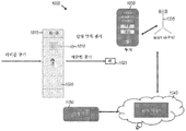
통신은 모바일 디바이스(1030)에, 또는 클라우드 플랫폼에 업링크하도록 Wi-Fi 라우터(1035) 또는 다른 무선 디바이스에 전달될 수 있다. 무선 능력은 ZigBee, Zwave, LoRa, Halo(새로운 Wi-Fi), 블루투스 및 블루투스 BLE를 포함할 수 있지만, 이에 한정되지 않는다.Communication may be communicated to the
데이터는 모바일 디바이스 상의 애플리케이션에 직접 및/또는 셀룰러 접속, Wi-Fi 라우터 또는 허브를 통해 클라우드 플랫폼 시스템(1045)에 직접 전달될 수 있다. 센서들은 통신 링크를 구축하기 전에 교정될 필요가 없다. 그것들은 디바이스의 초기 활성화 중에 또는 그 후에 교정될 수 있다.The data may be communicated directly to the application on the mobile device and / or to the
디바이스는 지능형 상태 관리를 이용하여 자가 교정할 것이다. 디바이스는 가속도계 또는 기타 센서를 사용하여 퍼니스 팬 모터가 꺼질 때(감소된 진동 또는 공기 유동) 및 팬 모터가 켜질 때(증가된 진동 또는 공기 유동)를 식별할 수 있다. 꺼진 상태는 시간이 지남에 따라 예컨대 기계 학습 알고리즘(1050)을 통해 디바이스를 교정하고 켜진 상태와 비교하는 데 사용될 것이다.The device will self-calibrate using intelligent state management. The device can use an accelerometer or other sensor to identify when the furnace fan motor is turned off (reduced vibration or air flow) and when the fan motor is turned on (increased vibration or air flow). The turned off state will be used over time to calibrate the device, e.g., through the
도 11은 필터 센서와 상호작용하는 모바일 디바이스의 구성 및 사용을 도시하는 블록 흐름도이다. 필터 센서와의 페어링이 발생하여, 모바일 디바이스를 통한 Wi-Fi 크리덴셜들의 입력을 허용할 수 있다. 이를 통해 필터 센서는 고객/사용자의 집 안의 라우터와 직접 통신할 수 있다. 필터로부터의 데이터의 업데이트는 성능(예컨대, 저하된 성능, 적절한 성능 또는 최적의 성능) 및 잔여 유효 필터 수명 중 적어도 하나를 나타내는 사용자 인터페이스를 사용자에게 제시하게 한다. 필터가 더럽거나, 막혔거나, 또는 달리 교체가 필요할 수 있다는 통지가 또한 전송될 수 있는데, 이는 사용자가 볼 수 있도록 모바일 디바이스 상에 디스플레이될 수 있거나, 또는 자동으로 교체 필터를 주문하거나 또는 사용자로 하여금 편리하게 교체 필터를 주문하는 옵션을 선택하도록 프로그래밍될 수 있다.11 is a block flow diagram illustrating the configuration and use of a mobile device that interacts with a filter sensor. Pairing with the filter sensor can occur, allowing input of Wi-Fi credentials via the mobile device. This allows the filter sensor to communicate directly with the router in the customer / user's home. The updating of data from the filter causes the user to present a user interface representing at least one of performance (e.g., degraded performance, appropriate performance or optimal performance) and remaining effective filter lifetime. A notification may also be sent that the filter may be dirty, clogged, or otherwise require replacement, which may be displayed on the mobile device for viewing by the user, or automatically order a replacement filter, Can be programmed to conveniently select an option to order a replacement filter.
일부 실시예들에서, 특정 사용자 요구사항들이 필터 교체에 대한 필요성을 결정하는 분석에 고려될 수 있다. 사용자는 특정 의학적 상태들, 예컨대, 꽃가루 알러지 또는 정상적인 공기질보다 더 좋은 공기질이 요구될 수 있는 기타 호흡기 질환을 나타내는 프로파일을 입력할 수 있다. 그러한 정보는 애플리케이션에 의해 상이한 필터를 추천하거나, 또는 교체가 필요한 필터를 나타내는 표시를 생성하기 위한 임계치를 변경하는 데 사용될 수 있다. 사용자의 요구사항에 적응하는 능력은 사용자에게 더 나은 전체적인 경험 및 스마트 필터 시스템의 용이한 사용을 제공하여, 필터의 상태를 더 밀접하게 추적해야 하는 사용자들을 편하게 해주거나 또는 더 나은 삶의 질에 요구되는 적절한 공기질을 제공할 수 없는 필터를 사용하는 것으로부터 그들을 구할 수 있다.In some embodiments, certain user requirements may be considered for analysis that determines the need for filter replacement. The user may enter a profile that indicates certain medical conditions, such as pollen allergy or other respiratory conditions that may require better air quality than normal air quality. Such information may be used by the application to recommend a different filter, or to change the threshold for generating an indication of a filter that needs to be replaced. The ability to adapt to the user's needs provides the user with a better overall experience and ease of use of the smart filter system to ease the users who need to track the state of the filter more closely or to improve the quality of life They can be obtained from using a filter that can not provide adequate air quality.
도 12는 필터의 각 면에 하나씩, 2개의 압력 센서(1410, 1415)를 활용하는 예시적인 시스템(1400)의 블록도이다. 2개의 압력 센서의 사용은 2개의 독립적인 압력 센서를 제공하여 필터 전(더러운 공기 화살표(1420)로 표시되는 더러운 면) 및 필터 후(깨끗한 공기 화살표(1425)에 의해 표시되는 깨끗한 면)의 공기 압력을 검출한다. 일 실시예에서, 시스템은 2개의 압력 센서(1410, 1415), 압력 차이를 결정하는 회로 및/또는 로직(1430)뿐만 아니라 라우터(1445)에서 표시되는 블루투스 BLE, 블루투스 또는 Wi-Fi를 통해 셀전화기(1440)와 통신하기 위한 무선통신장치(안테나(1435)에 의해 표현됨)를 포함한다.12 is a block diagram of an
코인 셀 유형 배터리가 시스템(1400)에 전력을 제공하도록 사용될 수 있다. 더 큰 배터리 팩 또는 다른 유형의 전원이 또한 더 긴 수명을 위해 사용될 수 있다. 업데이트의 형태의 데이터는 주기적으로, 예를 들어, 1분에 1회와 같이 제공될 수 있다. 더 빈번한 또는 덜 빈번한 업데이트 또는 센서 샘플링이 원하는 대로 제공될 수 있다. 덜 빈번한 업데이트는 필터가 원하는 파라미터들 내에서 기능할 것으로 예상되는 시간의 길이에 일치하는 배터리 수명을 보존하는 것을 도울 수 있다. 일 실시예에서 센서 판독치는 파스칼 단위 또는 물의 인치(공기 유동의 85 lpm에서의 델타 P)이다. 통신은 셀전화기에, 또는 클라우드 플랫폼에 업링크하도록 Wi-Fi 라우터 또는 기타 무선 디바이스에 전달될 수 있다. 데이터는 전화기 상의 애플리케이션에 직접 및/또는 Wi-Fi 라우터(1445)를 통해 클라우드 플랫폼 시스템에 전달될 수 있다. 압력 센서들은 사용 전에 교정될 필요가 없다. 일 실시예에서, 압력 센서들은 시스템의 초기 활성화 중에 교정될 수 있다.A coin cell type battery may be used to provide power to the
일 실시예에서, 2개의 압력 센서는 도 13의 블록 흐름도(1500)에 나타난 바와 같이 공장에서 또는 초기 셋업시에 서로에 대하여 교정될 수 있다. 디바이스의 교정 보정은 공기 유동이 0일 때 1510에서 수식 S1 = S2 + 교정 보정에 의해 표현될 것이다. 교정은 1520에서 팬 꺼짐 및 1530에서 팬 켜짐 상태의 압력들을 판독함으로써 수행될 수 있다. 1540에서, 센서 1 및 센서 2에 대하여 판독치의 평균값들이 결정되고, 1510에서 교정 보정에 제공된다.In one embodiment, the two pressure sensors can be calibrated to one another at the factory or at initial setup, as shown in block flow diagram 1500 of FIG. The calibration correction of the device will be represented by the formula S1 = S2 + calibration correction at 1510 when the air flow is zero. Calibration may be performed by reading the pressures at 1520 and at 1530 the pan-off state. At 1540, the mean values of the readings for
예시 압력 센서들은: AdaFruit BME280 I2c 또는 SPI 온도 습도 압력 센서, MPL3115A2 - I2C 기압/고도/온도 센서(각각 애드프룻 인더스트리 엘엘씨(Adafruit Industries, LLC)에서 입수가능함) 및 MPXM2010DT1 및 MPXM2010D(엔엑스피 유에스에이 인크(NXP USA, Inc.)에서 입수가능함)를 포함한다. 예시적인, 상업적으로 입수가능한 가속도계는 스위스 제네바 소재의 에스티마이크로일렉트로닉스(STMicroelectronics)의 LIS2DH12TR 디지털 가속도계이다. 센서들 중 임의의 하나 또는 둘 모두는 용이하게 상업적으로 입수가능한 재고 부품들일 수 있다.Exemplary pressure sensors include: AdaFruit BME280 I2c or SPI temperature and humidity pressure sensors, MPL3115A2-I2C pressure / altitude / temperature sensors (each available from Adafruit Industries, LLC) and MPXM2010DT1 and MPXM2010D (Available from NXP USA, Inc.). An exemplary, commercially available accelerometer is the LIS2DH12TR digital accelerometer from STMicroelectronics, Geneva, Switzerland. Any one or both of the sensors can easily be commercially available stock parts.
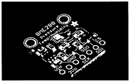
추가적인 예시적인 시스템에서, 하나 이상의 센서들은 필터의 깨끗한 면 및 더러운 면 상의 (필터 전후) 압력, 공기 유동, 공기질, 온도, 습도, 필터의 왜곡, 공기 유동 특징 및 진동을 모니터한다. 예시적인 습도 센서, AdaFruit BME280 I2c 또는 SPI 온도 습도 압력 센서가 도 14에 도시되어 있다.In a further exemplary system, the one or more sensors monitor pressure, air flow, air quality, temperature, humidity, filter distortion, air flow characteristics and vibration on the clean side and the dirty side of the filter. An exemplary humidity sensor, AdaFruit BME280 I2c or SPI temperature and humidity pressure sensor is shown in FIG.
실험실 규모의 퍼니스 실험용 시스템(1700)이 도 15에 표시된다. 제어형 팬 속력을 갖는 팬(1710)은 덕트 구조물의 중앙에 있는 필터(1720) 및 회로 기판의 형태의 센서 회로부(1725)를 갖는 시뮬레이션된 덕트 구조물을 통해 공기를 흡입한다. 센서 회로부(1725)는 위에서 기재한 바와 같이 필터 상태를 나타내는 하나 이상의 파라미터들을 측정하는 하나 이상의 센서들로부터 데이터를 수신하고 생성된 정보를 전송한다. 센서 회로부(1725)는 실시간 확인, 검색, 및 분석을 위하여 원격 플랫폼 상에 데이터를 자동으로 업로드 및 유지하는 사물 인터넷(IoT) 애플리케이션 프로토콜을 구현할 수 있다.A laboratory scale furnace
도 16은 사물 인터넷(IoT) 프로토콜을 통해 네트워크에 무선으로 커플링될 수 있는 회로부(1725)로부터 스트리밍되는 데이터의 예시를 도시한다.FIG. 16 illustrates an example of data streamed from
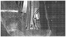
도 17은 더 큰 시험 환경을 제공하는 일반적인 가정용 퍼니스 덕트 구조물에 설치된 필터의 사진이다. 센서 팩들이 필터 전후에 설치될 수 있다. 필터와 모터 사이의 공간에 시험할 하나의 센서 팩이 보인다. 필터 전의 좌측에 제2 센서 팩이 있다(시험용/교정용). Wi-Fi 신호는 센서 팩이 삽입된 이 구성에서 문제없이 금속 퍼니스를 투과할 수 있다. 센서 팩은 예를 들어 고해상도 시험 데이터를 위해 매우 빠른 샘플링 속도를 제공하도록 전원에 연결된 "센서 햇(sensor hat)"을 구비한 Raspberry Pi3일 수 있다. 데이터는 IoT 플랫폼에 업로드되고 있다. 초기 시험들은 센서들이 필터 전 및 필터 후의 압력 차이를 잡아낼 수 있음을 나타내었다. 센서들은 여러 날에 걸쳐 "깨끗한" 필터로서 가동하여 더 긴 기간에 걸친 센서의 분산 및 민감도를 결정할 수 있다.Figure 17 is a photograph of a filter installed in a typical household furnace duct structure providing a larger test environment. Sensor packs can be installed before and after the filter. There is one sensor pack to test in the space between the filter and the motor. On the left side of the filter is a second sensor pack (for test / calibration). The Wi-Fi signal can pass through the metal furnace without problems in this configuration with the sensor pack inserted. The sensor pack may be, for example, a Raspberry Pi3 with a " sensor hat " connected to a power source to provide a very fast sampling rate for high resolution test data. The data is being uploaded to the IoT platform. Initial tests have shown that the sensors can catch pressure differences before and after the filter. Sensors can operate as a "clean" filter over several days to determine the dispersion and sensitivity of the sensor over a longer period of time.
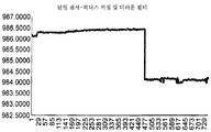
도 18은 팬이 처음에 꺼지고, 이어서 켜지고, 다시 꺼질 때 필터에 걸리는 압력의 차이를 도시하는 그래프이다. 팬이 꺼지면, 압력의 차이는 0이 아닌 경우 무시할 만하다. 위에 있는 선은 필터의 센서 상류로부터의 데이터를 표현하고, 아래 있는 선은 필터의 센서 하류로부터의 데이터를 표현한다. 주목할 점은 퍼니스가 그래프의 시작에서 꺼져 있고 또한 그래프의 끝에서도 꺼져 있으면, 두 선이 다시 만난다는 것이다.18 is a graph showing the difference in pressure applied to the filter when the fan is first turned off, then turned on, and then turned off. When the fan is off, the pressure difference is negligible if it is not zero. The upper line represents data from the sensor upstream of the filter, and the lower line represents data from the sensor downstream of the filter. Note that if the furnace is off at the beginning of the graph and is also off at the end of the graph, then the two lines will be seen again.
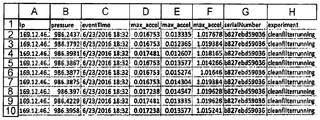
도 19는 스마트 필터를 포함하는 시스템의 동작 동안 전송 및 수집되는 정보를 나타내는 스프레드시트 기반의 표이다.Figure 19 is a spreadsheet-based table that shows information that is transmitted and collected during operation of a system including a smart filter.
필터 교체로 인해 개별적인 센서 유닛이 개시되는 시점에 퍼니스에 대한 동작 "상태"가 식별된다. 이러한 상태들은 다음을 포함한다:The state of operation " status " for the furnace is identified at the time when the individual sensor unit is started due to the filter replacement. These states include:
퍼니스 꺼짐 - 퍼니스는 낮은 레벨의 진동을 갖는 동안 주변 공기의 압력 레벨을 갖게 된다. Furnace Off - The furnace has a pressure level of ambient air while having a low level of vibration.
퍼니스 켜짐 깨끗한 필터 - 깨끗한 면 센서가 소정 레벨의 압력을 확립한다. Furnace on Clean filter - A clean surface sensor establishes a certain level of pressure.
퍼니스 켜짐 분산 1…n - 퍼니스는 시간이 지남에 따라 가동되면서 여러 잠재적인 규칙적인 "상태들"을 확립한다. 이 상태들은 사용중인 필터의 2 개월 단계 동안 확립된다.
퍼니스 켜짐 더러움 - 처음 2 개월 동안 확립된 퍼니스 켜짐 분산 상태들에 비교하여 막힘의 레벨들이 결정된다. Furnace on dirt - levels of clogging are determined relative to the furnace on dispersion states established during the first two months.
퍼니스 필터 교체 필요 - 이 상태는 퍼니스 필터가 사전결정된 상태에 도달하면, 예를 들어, 이전에 확립된 상태의 압력보다 압력이 평균 1.5 파스칼 작거나 또는 퍼니스 켜짐 동안 임의의 상태에 대하여 3.25 개월이 도달되었을 때 확립된다. Furnace filter replacement required - This condition is required when the furnace filter reaches a predetermined state, for example, when the pressure is less than the previously established pressure by an average of 1.5 pascals or 3.25 months for any condition during the furnace turn on .
완전한 크기의 퍼니스 상의 제1 실험 1로부터의 데이터 파일이 다음의 평균된 결과로 다음과 같이 보고되었다.The data file from the
필터 전 - Pi 시리얼 번호 43 - 꺼짐 교정 평균 986.3636Pre-filter - Pi serial number 43 - Off calibration average 986.3636
필터 후 - Pi 시리얼 번호 36 - 꺼짐 교정 평균 986.3614After Filter - Pi Serial Number 36 - Off Calibration Average 986.3614
필터 전 - Pi 시리얼 번호 43 - 깨끗함 가동 평균 986.2444Filter before - Pi serial number 43 - Clean running average 986.2444
필터 후 - Pi 시리얼 번호 36 - 깨끗함 가동 평균 985.8823After filter - Pi serial number 36 - Clean running average 985.8823
필터 전 - Pi 시리얼 번호 43 - 미지의 더러움 평균 986.0958Filter before - Pi serial number 43 - Unknown dirt average 986.0958
필터 후 - Pi 시리얼 번호 36 - 미지의 더러움 평균 985.2246After filter - Pi serial number 36 - unknown dirt average 985.2246
필터 전 - Pi 시리얼 번호 43 - 더러움 0.74 평균 986.1727Filter before - Pi serial number 43 - dirt 0.74 average 986.1727
필터 후 - Pi 시리얼 번호 36 - 더러움 0.74 평균 985.2684After filter - Pi serial number 36 - dirt 0.74 average 985.2684
필터 전 - Pi 시리얼 번호 43 - 더러움 1.54 평균 986.3910Filter before - Pi serial number 43 - Dirt 1.54 Average 986.3910
필터 후 - Pi 시리얼 번호 36 - 더러움 1.54 평균 984.1002After filter - Pi serial number 36 - dirt 1.54 average 984.1002
초기 결과들은 저비용 센서들이 퍼니스의 필터 전 및 필터 후 섹션 사이의 압력 차를 확립할 수 있는 능력을 나타낸다. 결과들은 또한 하나 이상의 센서들을 이용하여 시간에 대한 상태들을 효과적으로 구축하는 시스템의 능력을 제안한다. "퍼니스 꺼짐" 상태는 하나 이상의 센서들이 시간에 대한 대기압 변화뿐만 아니라 퍼니스 구성 변경에 대해 교정하도록 허용할 것이다.Initial results indicate the ability of the low cost sensors to establish a pressure differential between the pre-filter and post-filter sections of the furnace. The results also suggest the ability of the system to effectively construct states over time using one or more sensors. The " furnace off " state will allow one or more sensors to calibrate for furnace configuration changes as well as atmospheric pressure changes over time.
알고리즘 방법Algorithmic method
하나 이상의 압력 센서들뿐만 아니라 가속도계 센서들을 포함하는 시스템이 시간에 대한 퍼니스의 상태들을 확립할 수 있다:A system including one or more pressure sensors as well as accelerometer sensors can establish the states of the furnace for time:
S0 - 필터 설치 - 퍼니스 꺼짐S0 - Filter Installation - Furnace Off
S1 - 필터 깨끗함 - 퍼니스 켜짐S1 - Filter clean - Furnace on
S2..n - 1 내지 2 개월 내의 자가 특징 상태들S2..n - self-feature states within 1 to 2 months
Sr - 교체 필요 - S0 또는 켜진 상태에 있는 동안 S0에 대하여 필터 전 압력 센서로부터 2 파스칼 이상의 차이 또는 S2..n 자가 특징 상태들 중 임의의 상태에 비교했을 때 1.5 파스칼 이상의 평균 변화에 의해 특징지어짐.Sr - Replacement Required - characterized by an average change of more than 1.5 Pascals when compared to any of two or more Pascal differences from the pre-filter pressure sensor or S2..n self feature states for S0 while in S0 or on state. load.
필터 매체 상태를 직접적으로 나타낼 수 있는 상이한 파라미터들을 감지하는 상이한 유형의 센서들이 상이한 실시예들에서 사용될 수 있기 때문에, 더 일반적인 알고리즘은 단지 압력 센서들의 사용에만 한정되지 않는 유사한 단계들을 포함할 수 있다. "교체 필요" 임계치는 공기 유동의 변화, 모터 부하의 변화, 진동의 변화, 및 적절한 센서들에 의해 감지되는 기타 파라미터들에 기초할 수 있고, 이는 아래에 추가적으로 상세하게 기재되는 바와 같다.Since different types of sensors that sense different parameters that can directly indicate filter media conditions can be used in different embodiments, a more general algorithm may include similar steps that are not limited solely to the use of pressure sensors. The " replace needed " threshold may be based on changes in air flow, changes in motor load, changes in vibration, and other parameters sensed by appropriate sensors, as described in further detail below.
추가적인 방법론적 세부사항Additional Methodological Details
상태 값 - 상태의 값은 다중단계 프로세스를 통해 계산된다. 일차 결정론적 상태는 퍼니스가 켜지거나 또는 꺼진 상태이다. 제2 단계는 공기 유동, 진동 및 압력 안정화를 위하여 퍼니스가 켜지거나 또는 꺼진 후 2분의 지연과 같은, 안정화 기간이다. 제3 단계는 소정 기간 동안(예컨대, 2분) 데이터를 수집하는 것이다. 이동 평균의 2배인 이상점 데이터는 제거되고, 해당 기간에 대한 이동 평균은 필터 후 압력 센서에 대하여 확립된다. 진동(가속도계 데이터)은 퍼니스의 켜짐/꺼짐 상태를 추가적으로 결정하는 데 사용될 수 있다. 초기 실험은 단일 센서가 이 결정에 사용될 수 있음을 제안한다. State Value - The state value is calculated through a multi-step process. The primary deterministic state is that the furnace is on or off. The second stage is a stabilization period, such as a delay of 2 minutes after the furnace is turned on or off for air flow, vibration and pressure stabilization. The third step is to collect data for a predetermined period (e.g., 2 minutes). Point data that is twice the moving average is removed and a moving average for that period is established for the post-filter pressure sensor. Vibration (accelerometer data) can be used to further determine the on / off state of the furnace. Initial experiments suggest that a single sensor can be used for this determination .
추가적인 기여 요인들Additional Contributing Factors
실내 공기 오염 정보(미립자 및 기타 오염물들)가 공기 여과 매체를 교체할 필요성의 정확도를 개선하는 데 사용될 수 있다.Indoor air pollution information (particulates and other contaminants) can be used to improve the accuracy of the need to replace the air filtration media.
메타데이터 / 일반적인 설문조사 정보 - 흡연, 촛불의 사용, 반려동물 소유 정보를 이용하여 알고리즘이 더 적극적으로 교체를 결정할 수 있도록 통지할 수 있다.Metadata / General Survey Information - Smoking, use of candles, and companion animal proprietary information can be used to inform the algorithm that the algorithm can more aggressively determine replacement.
일반적 건축물 구성 - 창문 열림/닫힘, 카펫트뿐만 아니라 기타 정보가 알고리즘에 통지하는 데 사용될 수 있다.General building configuration - windows open / closed, carpets as well as other information can be used to notify the algorithm.
실외 공기 오염 - 적극적인 교체를 결정하기 위하여 공기질 모니터링 사이트로부터 정보가 수집될 수 있다.Outdoor air pollution - Information may be collected from air quality monitoring sites to determine active replacement.
분석들이 필터의 수명에 걸쳐 공기질 조언, 퍼니스 상태 및 필터 교체 상태를 필터링하고 제공하는 데 사용될 수 있다. 시스템은 코인 셀 배터리에 의한 동력식일 수 있다. 더 긴 수명을 위해 더 큰 배터리 팩이 또한 사용될 수 있다. 공기 유동, 진동, 가열 차 또는 다른 수단들을 이용하여 전력을 생성하고 배터리를 재충전하는 데 전력 수확기가 사용될 수 있다. 기타 전력 공급원들 및 저장 방법들이 필요에 따라 사용될 수 있다. 시스템은 다양한 시간 간격에서, 예컨대 1분당 수차례 업데이트를 제공할 수 있다. 더 빈번한 업데이트 또는 센서 샘플링이 제공될 수 있다. 업데이트의 빈도는 공기 이동에 의해 제어될 수 있다.Analyzes can be used to filter and provide air quality advice, furnace status, and filter replacement status over the lifetime of the filter. The system may be powered by a coin cell battery. Larger battery packs may also be used for longer life. A power harvester may be used to generate power and recharge the battery using air flow, vibrations, heated cars or other means. Other power sources and storage methods may be used as needed. The system may provide updates at various time intervals, e.g., several times per minute. More frequent updates or sensor sampling may be provided. The frequency of updates can be controlled by air movement.
공기 압력은 압력 차이를 결정할 수 있도록 필터 전후에 측정될 수 있다. 다수의 센서들을 사용하여 개별적인 센서들의 고장을 보정할 수 있다. 필라멘트 및 공기 유동 센서들을 포함하여 필터 전후의 공기 챔버 내의 공기 난기류의 지도를 제공할 수 있다. 공기 난기류 정보를 사용하여 필터의 막힘 또는 하위 최적화된 성능 또는 퍼니스 제어를 결정할 수 있다.The air pressure can be measured before and after the filter to determine the pressure difference. Multiple sensors can be used to compensate for individual sensor failures. Filaments and air flow sensors can be provided to provide a map of air turbulence in the air chambers before and after the filter. Air turbulence information can be used to determine clogging or sub-optimized performance or furnace control of the filter.
또한 필터 전후에 공기질을 모니터하여 미립자 및 비-대기 기체 값들을 제공하여 처리 전후의 필터 성능 및 공기질을 모니터할 수 있다. 공기질 모니터/센서들은 또한 HVAC 시스템 외측 및 빌딩 또는 집 안에 배치될 수 있다. 공기 스트림의 공기 온도가 또한 모니터될 수 있다. 공기 스트림의 공기 습도가 또한 모니터될 수 있다. 변형 센서들을 사용하여 필터의 수명 동안 물리적 필터 형상의 왜곡을 모니터할 수 있다. 변형 게이지 능력이 필터의 필라멘트 안에 직조될 수 있다.The air quality can also be monitored before and after the filter to provide particulate and non-atmospheric gas values to monitor filter performance and air quality before and after treatment. Air quality monitors / sensors may also be placed outside the HVAC system and in buildings or houses. The air temperature of the air stream can also be monitored. The air humidity of the air stream can also be monitored. The strain sensors can be used to monitor the distortion of the physical filter shape for the lifetime of the filter. The strain gauge capability can be woven into the filaments of the filter.
방향성(자이로스코프) 및 무-방향성(가속도계) 측정치들이 센서들에 의해 제공되어 퍼니스 시스템의 컴포넌트들 내에서 상대적인 변형을 초래할 수 있는 진동을 이해할 수 있다. 통신 능력들이 포함되어 정보를 셀전화기와 같은 모바일 디바이스에, 또는 클라우드 플랫폼에 업링크하도록 Wi-Fi 라우터 또는 기타 무선 디바이스에 제공할 수 있다. 무선 능력은 ZigBee, Zwave, LoRa, Halo(새로운 Wi-Fi), 블루투스 및 블루투스 BLE를 포함할 수 있지만, 이에 한정되지 않는다. 통지를 포함하는 데이터는 모바일 디바이스 상의 애플리케이션에 직접 및/또는 Wi-Fi 라우터를 통해 클라우드 플랫폼 시스템에 전달될 수 있다. 주목할 점은 센서들이 미리 교정될 필요가 없다는 것이다. 그것들은 디바이스의 초기 활성화 시에 교정될 수 있다.Directional (gyroscope) and non-directional (accelerometer) measurements may be provided by the sensors to understand the vibrations that may result in relative variations within the components of the furnace system. Communication capabilities may be included to provide information to a Wi-Fi router or other wireless device to uplink to a mobile device, such as a cell phone, or to a cloud platform. Wireless capabilities may include, but are not limited to, ZigBee, Zwave, LoRa, Halo (new Wi-Fi), Bluetooth and Bluetooth BLE. The data including the notification may be communicated directly to the application on the mobile device and / or to the cloud platform system via a Wi-Fi router. Note that the sensors need not be pre-calibrated. They can be calibrated at the initial activation of the device.
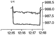
도 20은 퍼니스 또는 팬이 꺼지고, 이어서 켜질 때 단일 하류측 압력 센서로부터의 판독치를 나타내는 그래프이며, 필터는 더러워서 교체가 필요하다고 알려져 있다. 주목할 점은, 꺼졌을 때 거의 986.5 파스칼에서 켜졌을 때 984.5 파스칼 미만으로 이동하여, 2 파스칼 이상만큼 압력이 변한다는 것이다. 팬이 켜지고 꺼질 때 둘 모두의 압력을 기록함으로써, 그 차이는 감산에 의해 알 수 있다. 2 파스칼의 임계치와의 비교는 임계치가 도 20에 도시된 데이터에 기초하여 초과됐음을 나타낸다.Figure 20 is a graph showing readings from a single downstream pressure sensor when the furnace or fan is turned off and then on; it is known that the filter is dirty and needs to be replaced. It should be noted that when turned off, it travels less than 984.5 pascals when turned on at approximately 986.5 pascals, and the pressure changes by more than 2 pascals. By recording the pressure of both when the fan is turned on and off, the difference can be known by subtraction. A comparison with a threshold of 2 pascals indicates that the threshold is exceeded based on the data shown in FIG.
교정되지 않은 파스칼(저비용 센서)에서의 압력은 X 축 상의 시간 증분과 함께 시간에 대하여 좌측(Y-축)(982 내지 987) 상에 있다. 샘플 실험 데이터는 퍼니스가 켜질 때 986.5000의 높은 압력에서 대략 984.0000으로 꺼진 상태가 변하는 것을 보여준다. 압력 차는 공기 압력을 대략 984로 감소시키는 막힌 팬 뒤에서 퍼니스 팬의 팬 동작에 의해 막히는 주변 공기 압력(대략 986)의 차이에 의해 발생된다.The pressure at the uncalibrated Pascal (low cost sensor) is on the left (Y-axis) 982 to 987 with respect to time with time increment on the X axis. The sample experimental data shows that when the furnace is turned on, the off state changes to approximately 984.0000 at a high pressure of 986.5000. The pressure difference is caused by the difference in ambient air pressure (approximately 986) clogged by the fan action of the furnace fan behind a clogged fan that reduces the air pressure to approximately 984.
단일 압력 센서를 이용하여 압력 변화의 신속한 성질에 의해 퍼니스 상태(켜짐 또는 꺼짐)를 결정할 수 있다. 대기압 변화는 더 느리게 일어난다. 켜짐/꺼짐 기간들은 상태 Sr(필터의 교체가 필요함)의 결정을 위한 비교기를 결정하는 데 사용될 수 있다.A single pressure sensor can be used to determine the furnace condition (on or off) by the fast nature of the pressure change. Atmospheric pressure changes occur more slowly. The on / off periods can be used to determine a comparator for determining the state Sr (filter replacement is required).
여러 상이한 예시적인 실시예들이 위에 기재되었다. 도 21은 필터의 ID를 제공하고, 필터 매체 상태를 감지하고, 선택적으로 공기질을 감지하기 위한 다양한 옵션들을 구비한 스마트 필터의 블록도 표현이다. 옵션들에 관한 추가적인 상세사항들에는 도 22의 논의가 제공된다.A number of different exemplary embodiments have been described above. 21 is a block diagram representation of a smart filter with various options for providing the ID of the filter, sensing the filter medium status, and optionally sensing the air quality. Additional details regarding the options are provided in the discussion of FIG.
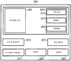
다양한 옵션들을 갖는 전체 스마트 필터 시스템 모습이 이제 기재된다. 도 22는 스마트 필터 시스템(2400) 내의 다수의 구성요소들 및 대안적인 구성요소들의 블록도 표현이다. 시스템(2400)은 3개의 주요 구성요소, 사용시 자가-인식하는 공기 필터(2410), 필터(2410)로부터 데이터를 수집하는 소프트웨어 알고리즘들(2412), 및 관련 정보를 디스플레이, 예컨대, 모바일 디바이스 디스플레이 상에 디스플레이하기 위한 사용자 인터페이스(2414)를 포함한다. 모바일 디바이스는 랩톱 컴퓨터, 셀룰러 전화기, 태블릿, 또는 정보를 수신, 프로세싱, 및 디스플레이할 수 있는 기타 디바이스일 수 있다.The entire Smart Filter system with various options is now described. FIG. 22 is a block diagram representation of a number of components and alternative components within the
자가-인식 필터(2410)는 필터에 통합되거나, 설치 동안 필터에 부착되거나, 또는 필터를 고정시키는 프레임 내의 회로에 의해 자가-인식할 수 있다. 필터가 설치되면, 그것은 그것이 특정 브랜드, 유형, 또는 크기의 필터임을 식별하고, 동작 동안 필터에 관한 디지털 데이터를 제공할 수 있다. 또한, 필터는 시스템(2400)을 통해 이동하는 공기의 공기질에 관한 데이터를 제공할 수 있다.The self-
소프트웨어 알고리즘들(2412)은 하나 이상의 센서들로부터 데이터를 수집하고, 향후 분석을 위해 데이터를 조작하고, 향후 전송 및 보고를 위해 (다수의 수집 세션들로부터의) 다수의 데이터 스트링들을 저장한다.
사용자 인터페이스(2414)는 최종 사용자가 용이하게 필터 성능을 볼 수 있게 하는 포맷으로 데이터를 제시한다. 그것은 이력 데이터 및/또는 현재 상태를 제공할 수 있다. 그것은 필터 상태 및 사용 시간에 기초하여 필터 교체까지의 예상 시간을 제공할 수 있다. 그것은 경고 및 자동 주문 능력을 포함하는 데이터를 소비자에게 유용한 임의의 포맷으로 제공할 수 있다. 실내, 빌딩, 시설, 또는 캠퍼스 레벨에서의 공기질 데이터를 디스플레이할 수 있다. 공기질 데이터는 외부 공기질 모니터링 서비스, HVAC 시스템 외측의 공기질 모니터링 디바이스, 또는 HVAC 시스템 내의 하나 이상의 센서들로부터 추출될 수 있다.The
필터 ID(2416)는 수동(2418) 또는 능동(2420)일 수 있다. 수동 ID 실시예들은 필터가 삽입되면 폐쇄되는 자기 스위치(2422)의 사용을 포함하거나, 또는 필터가 삽입되면 회로를 활성화하는 필터에 내장된 단순한 소켓(2424)을 가짐으로써 일 수 있다. 능동 수단들(2420)은 필터 및 센서 회로가 설치되면 공진하는, HVAC 디바이스에 부착된 수동 공진 회로(2426)에 의해 달성될 수 있다. RF ID 태그들(2428), NFC 태그들(2430)과 같은 다른 수단들을 이용하여 필터를 검출할 수 있거나, 또는 바코드 또는 QR 코드(2432)를 판독함으로써 필터를 검출할 수 있다. 다른 실시예에서, 필터 ID는 센서(2431) 상에 프로그래밍되거나, 센서로부터 블루투스 또는 기타 무선 통신 프로토콜을 통해 모바일 디바이스 또는 클라우드 플랫폼에 전달될 수 있다.
매체 상태(2434)는 전자 데이터 수집 회로 및 센서(2436)에 의해 결정되고, 통신 블록들(2438) 아래에 도시된 무선 전송에 의해 보고될 수 있다. 필터의 상태를 평가하기 위하여 사용될 수 있는 다양한 센서들(2436)이 있다. 물리적 센서(2440)는 변형 게이지(2442)를 이용하여 필터의 궁극적인 휨을 평가할 수 있다. 사용될 수 있는 기타 센서들은 광학(2444), 압력(2446), 공기 유동(2448) 또는 진동(2450)을 포함한다. 이러한 센서들의 각각의 유형의 다수의 상이한 버전들이 존재한다. 압력 센서(2446)는 시간이 지남에 따라 압력을 합계하거나 팬이 켜지고 꺼질 때 압력 측정치들을 비교할 수 있는 차압 센서(2452) 또는 단일 압력 센서(2454)일 수 있다.
광학(2444) 매체 상태 감지는 예를 들어 광검출기를 통해 매체를 투과하는 광을 측정함으로써 포울링(fowling)(2456)을 검출할 수 있다. 공기 유동(2448)은 팬 동작을 나타낼 수 있으며, 이는 필터의 상태를 결정하기 위하여 단일 하류 필터로부터의 압력 측정치와 함께 사용될 수 있다. 추가적인 실시예들에서, 공기 유동 센서들은 시간에 대한 공기 유동의 변화를 측정하는 데 사용될 수 있으며, 감소된 공기 유동은 필터 매체의 열악한 상태와 연관된다. 공기 유동의 감소에 대응하는 임계치는 필터가 교체되어야 하는지 결정하는 데 사용될 수 있다. 공기 유동은 예를 들어 진동 센서(2460), 열전 센서(2462), 또는 휨 센서(2464)(일 실시예에서 압전 소자 계열)를 포함하는 전기 수단(2458)에 의해 측정될 수 있다. 감지의 기계적 수단(2466)은 공기 난기류를 측정하기 위한 베인 기반 센서(2468)를 포함할 수 있으며, 이는 팬 동작뿐만 아니라 필터 매체 상태를 표현할 수 있는데, 그 이유는 난기류가 필터 매체 상태의 열화에 응답하여 변할 수 있기 때문이다. 이들 센서들의 각각은 팬의 동작에 관한 정보를 제공한다. 일부 실시예들에서, 팬의 동작은 팬 모터 상의 부하에 대한 표시를 제공하기 위하여 팬에 대한 전류를 측정함으로써 검출될 수 있으며, 이는 필터 매체의 상태를 직접적으로 나타낼 수 있다.Optical 2444 Media state detection can detect
다수의 센서들로부터의 데이터가 수집되면, 데이터는 여러 다양한 방식들로 융합되어 필터 매체 상태를 결정할 수 있다. 예를 들어, 일 실시예에서 팬 동작을 나타내는 데이터가 단일 하류 압력 판독치와 함께 사용될 수 있다. 추가적인 실시예에서 진동 정보는 압력과 조합될 수 있다. 추가적인 실시예들에서 다수의 진동 및 난기류 측정치들이 사용될 수 있다. 다수의 상이한 센서들이, 개별적으로 또는 조합하여 정보를 제공할 수 있으며, 다양한 실시예들에서, 임의의 센서의 정보 또는 센서들의 정보로부터 또는 다수의 센서들로부터 융합된 정보로부터 필터 매체의 상태가 계산될 수 있다.Once the data from the multiple sensors is collected, the data can be fused in a variety of different ways to determine the state of the filter media. For example, in one embodiment, data indicative of fan operation may be used with a single downstream pressure reading. In a further embodiment, the vibration information can be combined with the pressure. In further embodiments, multiple oscillation and turbulence measurements may be used. A number of different sensors may provide information individually or in combination, and in various embodiments, the state of the filter medium from information of any sensors or information from sensors, or from information fused from multiple sensors, .
수집되는 데이터는 통신(2438) 아래의 하나 이상의 옵션들에서 전달될 수 있다. 무선 수단에 의한 통신은 다양한 무선 프로토콜들, 예컨대, 무선 2.4 ㎓ 또는 5 ㎓, 블루투스 또는 블루투스 BLE(2470), ZigBee(2472), Zwave(2474), Halo, 또는 2476에 표현된 다른 표준 또는 커스텀 프로토콜을 이용하여 수행될 수 있다.The collected data may be delivered in one or more options under
센서들을 포함하는 회로부를 위한 전력(2478)은 다양한 공급원들로부터 올 수 있다. 하나의 옵션은 배터리(2480)이다. 대안적으로, 회로를 동작시키기 위한 에너지가 환경으로부터 수확(2482)될 수 있다. 예시들은 HVAC 시스템이 동작중일 때, 예컨대 터빈(2486) 또는 압전(2489) 또는 유도 발전기(2490)를 구비한 발진 리본을 활용하는 진동(2488)을 통해 공기 이동(2484)으로부터 전력을 생성하는 디바이스일 수 있다. 번갈아 열전 효과(2492)를 이용하여 전력이 생성될 수 있거나, 또는 RF 전송 신호(2494)를 이용하여 외부에서 전력이 공급될 수 있다.The
공기질(2496)은 여러 요인들에 따라 수많은 방식으로 정의될 수 있지만, 센서들(2498)을 통한 깨끗한 공기 면 상의 미립자의 측정치, VOC 측정, 주어진 실내 또는 빌딩 등에서의 미립자의 측정치를 포함할 수 있다.
소정 상황 하에서, 스마트 필터 시스템은 하나의 센서 또는 다수의 센서들로부터의 데이터에만 기초하여 매체 상태를 결정하기에 충분한 정보가 부족할 수 있다. 예를 들어, 사용자는 집을 일주일간 떠나지만, 그의 또는 그녀의 HVAC 시스템은 가동되도록 할 수 있다. 다른 예로서, 사용자는 무선 통신 신호의 도달을 넘어서 집 또는 시설 내의 위치로 이동할 수 있다. 각각의 환경은 센서와 사용자의 모바일 디바이스 간의 데이터 통신의 잠재적 손실을 초래하지만, 필터 상태는 계속해서 열화될 것이다. 통신 손실의 지속기간에 따라, 사용자에게 보고되는 매체 상태는 필터 매체의 상태를 정확하게 반영하지 않을 수 있다. 이들 및 다른 상황들에서, 필수적인 기간 동안 센서 데이터에 대한 예측 필터 교체 알고리즘의 출력을 보완하는 것이 가능할 수 있다.Under certain circumstances, the smart filter system may lack sufficient information to determine the media condition based only on data from one sensor or multiple sensors. For example, a user may leave the house for a week, but his or her HVAC system may be running. As another example, a user may move beyond the reach of a wireless communication signal to a location in a house or facility. Each environment will cause a potential loss of data communication between the sensor and the user ' s mobile device, but the filter condition will continue to deteriorate. Depending on the duration of the communication loss, the media state reported to the user may not accurately reflect the state of the filter media. In these and other situations, it may be possible to compensate for the output of the prediction filter replacement algorithm for the sensor data for a required period of time.
일 예에서, 누락 데이터는 HVAC 팬 실행시간의 함수로서 교체 상태를 추정함으로써 보완된다. 팬 실행시간은 실외 날씨 데이터를 이용하여 추정될 수 있고, 특정 공기 필터 및/또는 HVAC 시스템 동작 상태에 관련된 파라미터들, 예컨대, 거주 파라미터들, HVAC 사용 파라미터들, 사용자 선호 파라미터들, 및 필터 파라미터들에 따라 조정될 수 있다. 날씨 데이터는 특정 지역에 대하여, 예를 들어, 온라인 데이터 서비스로부터 획득될 수 있다. 날씨 데이터는 공기 필터 실행시간을 추정하는 데 사용될 수 있고, 공기 필터 실행시간은 공기 필터의 교체 상태를 추정하는 데 사용될 수 있다. 팬 실행시간의 함수로서 필터 교체 상태를 추정하기 위한 예시적인 방법이, 전체적으로 본 명세서에 참고로 포함된, 국제출원 공개 WO 2016/089688(폭스(Fox) 등)에 기재되어 있다.In one example, the missing data is supplemented by estimating a replacement state as a function of the HVAC fan run time. The fan execution time may be estimated using outdoor weather data and may include parameters related to the specific air filter and / or HVAC system operating status, such as residence parameters, HVAC usage parameters, user preference parameters, and filter parameters . ≪ / RTI > The weather data may be obtained for a particular area, for example, from an online data service. The weather data can be used to estimate the air filter execution time, and the air filter execution time can be used to estimate the replacement state of the air filter. An exemplary method for estimating the filter replacement state as a function of fan run time is described in International Application Publication No. WO 2016/089688 (Fox et al.), Which is incorporated herein by reference in its entirety.
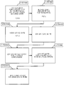
도 23는 센서 데이터와 필터 상태의 보고 시 추정된 상태 사이의 시프트를 위한 예시적인 시퀀스를 도시한다. 단계(3000) 및 "시간 0"에서 자가-인식 필터와 모바일 디바이스 또는 클라우드 플랫폼 사이에 통신 링크가 확립된다. 단계(3100) 및 "시간 1"에서, 통신은 센서로부터 표준이하의 데이터를 제공하거나 또는 아무런 데이터도 제공하지 않는다. 예를 들어, 주어진 출력 파라미터에 배정된 신뢰값이 충족되지 않거나 또는 초과된 경우, 데이터는 표준이하일 수 있다. 단계(3200) 및 "시간 2"에서, 표준이하 또는 미흡한 데이터의 기간이 시프트 임계치에 도달하거나 또는 초과하며, 이는 예컨대, 성공적인 통신 링크들 또는 예상 결과들 사이의 시간의 양에 기초할 수 있다. 시프트 임계치가 초과되면, HVAC 시스템에 관련된 지리적 지역에 대한 실외 날씨 데이터가 단계(3300)에서 획득된다(예컨대, 온라인 데이터 서비스로부터 전자적으로 검색됨). 실외 날씨 데이터는 센서(들)의 데이터와 동시에 수집될 수 있거나, 또는 그러한 수집은 시프트 임계치에 도달 시 트리거될 수 있다. 단계(3400)에서, 공기 필터의 교체 상태는 실외 날씨 데이터를 이용하여 근사화된다. 예를 들어, 실외 날씨 데이터는 공기 필터 실행시간을 추정하는 데 사용되고, 공기 필터 실행시간은 공기 필터의 교체 상태를 추정하는 데 사용된다. 추정은 사용자 인터페이스를 통해 사용자에게 제공될 수 있고, 사용자 인터페이스는 센서 데이터에 주로 전제된 추정과 유사한 감각적 경험을 공유하거나 공유하지 않을 수 있다. 단계(3500)에서, 자가-인식 필터는 사용자의 모바일 디바이스와 통신 링크를 확립하고/하거나 관련 출력 파라미터들은 "시간 3"에서 수용가능한 것으로 간주된다. 시스템은 즉시(또는 거의-즉시) 센서로부터 수신된 데이터에 기초하여 필터 상태를 예측하도록 다시 시프트할 수 있거나, 또는 단계(3700)에서 복귀 임계치를 초과하는 기간 동안 적절한 링크가 확립될 때까지 날씨-기반 추정에 기초하여 계속해서 동작할 수 있다.Figure 23 shows an exemplary sequence for a shift between sensor data and the estimated state upon reporting of the filter state. A communication link is established between the self-aware filter and the mobile device or cloud platform at step 3000 and "
실험은 2개의 센서를 이용하여, 1개는 필터 앞에 1개는 필터 뒤에 두고, 상이한 상태들(조건들) 동안 다음의 결과를 생성했다. P1 센서와 P2 센서(각각 필터 전 및 필터 후) 사이의 압력 차이를 이용하는 것이 필터 막힘 측정치에 대한 결정으로서 잘 이해된다. 필터 전의 단일 센서 또는 필터 후의 단일 센서가 필터 막힘을 결정하는 데 충분한 정보를 제공할 수 있는지 결정하는 것이 이전에는 이해되지 않았다.Experiments were carried out using two sensors, one before the filter and one after the filter, producing the following results for different conditions (conditions). Using the pressure difference between the P 1 sensor and the P 2 sensor (before and after the filter respectively) is well understood as a determination of the filter clog measurement. It has not previously been understood that a single sensor before a filter or a single sensor after a filter can provide sufficient information to determine filter clogging.
실험용 퍼니스에 대한 동작의 상이한 상태들 동안의 데이터의 샘플은 다음의 그래프 데이터를 제공한다.A sample of data during different states of operation for the laboratory furnace provides the following graph data.
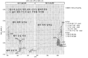
도 24는 시간이 지남에 따라 가변 조건 하에서 필터에 걸린 차압을 나타내는 다수의 압력 측정치들을 도시한다. 범례는 참조 번호를 갖는 다양한 요인들을 나타낸다. 범례에서 우측에 열거된 상이한 상태들(요인(실험))은 다음과 같다:24 shows a number of pressure measurements showing the differential pressure across the filter under variable conditions over time. The legend represents various factors with reference numbers. The different states (factors (experiments)) listed on the right side of the legend are:
깨끗한필터가동(2510) - 이것은 팬을 구비한 퍼니스가 새로운 깨끗한 필터로 가동되는 것이다Clean filter operation (2510) - This is because the furnace with the fan is run with a new clean filter
더러움0.74dP(2520) - 0.74 인치의 물의 값을 갖는 막힌 필터Clogged filter with a dirt value of 0.74 dP (2520) - 0.74 inches of water
더러움1.54dP(2530) - 1.54 인치의 물의 값을 갖는 막힌 필터(0.74보다 더 막힘)Dirt 1.54 dP (2530) - clogged filter with a water value of 1.54 inches (more clogged than 0.74)
꺼짐교정(2540) - 퍼니스는 가동되지 않고, 압력은 두 챔버 내에서 대기압과 동등해진다Off Calibration (2540) - The furnace is not running and the pressure equals atmospheric pressure in both chambers
미지의더러움가동(2550) - 미지의 여과 레벨의 막힌 필터.Unknown dirt action (2550) - Clogged filter of unknown filtration level.
도 25, 도 26, 도 27, 도 28, 도 29, 및 도 30은 유사한 범례를 활용하며, 참조 번호의 처음 두자리는 도면 번호를 나타내고, 뒤의 두자리는 도 24의 것들과 동일하다.Figures 25, 26, 27, 28, 29, and 30 utilize similar legends, wherein the first two digits of the reference numerals indicate the reference numerals, and the second two digits are the same as those of Figure 24.
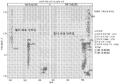
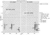
도 25는 필터가 삽입되는 덕트 내의 y-방향으로의 진동을 측정하는 가속도계 센서로부터 수집된 데이터를 도시한다. 도 26은 유사하게 x-방향으로의 진동의 측정치들을 도시한다. 도 27은 유사하게 z-방향으로의 진동의 측정치들을 도시한다. 도 28은 y-방향으로의 시간에 대한 가속도계 결과들을 도시한다. 도 29는 x-방향으로의 시간에 대한 가속도계 결과들을 도시한다. 도 30은 z-방향으로의 시간에 대한 가속도계 결과들을 도시한다.Figure 25 shows data collected from an accelerometer sensor that measures vibration in the y-direction within the duct into which the filter is inserted. Figure 26 similarly shows measurements of vibration in the x-direction. Figure 27 similarly shows measurements of vibration in the z-direction. Figure 28 shows accelerometer results for time in the y-direction. Figure 29 shows accelerometer results for time in the x-direction. Figure 30 shows accelerometer results for time in the z-direction.
주의: 요인(ip)은 2개의 상이한 센서를 구분한다. 169.12.46.245는 하류인 반면, 169.12.46.250은 상류이다. 필터가 더러울수록, 하류에서 압력 강하가 더 커진다. 상류 센서들은 현저한 압력 차이를 식별하지 않는다(우측의 그래프). 이러한 발견들은 단일 압력 센서가 사용된다면, 압력 센서는 전형적으로 하류측(필터 후)에 배치되어야 한다는 것을 제안한다.Note: Factor (ip) distinguishes two different sensors. 169.12.46.245 is downstream, while 169.12.46.250 is upstream. The dirtier the filter, the greater the pressure drop downstream. Upstream sensors do not identify significant pressure differences (right-hand graph). These findings suggest that if a single pressure sensor is used, the pressure sensor should typically be placed on the downstream side (after the filter).
압력 차는 막힌 필터와 공기를 흡인하는 팬 사이에서 흡입에 의해 생성된다.The pressure difference is created by suction between a clogged filter and a fan that draws in air.
P1 = 상류 센서 압력P 1 = upstream sensor pressure
P2 = 하류 센서 압력P 2 = downstream sensor pressure
![]()
![]()
T = 시간T = time
단일 센서가 하류(필터 후)에서 작동할 수 있고, 시스템은 센서 성능을 보조하기 위하여 시간뿐만 아니라 퍼니스의 상태도 알 수 있다. 상태는 퍼니스가 가동중인지 식별하기 위하여 가속도계 정보를 통해 결정될 수 있고, 또는 대안적으로 상태는 압력 측정치들의 시간적 분석에 의해 추론될 수 있다. 단순히 높고 낮은 판독치를 분리하고 그것들을 평균화하는 것은 어떤 측정치들이 퍼니스의 상태에 대응하는지 명백하게 식별할 수 있다. 퍼니스가 꺼졌을 때의 압력을 결정하는 것은 현재 기압에 대한 기준선을 결정하는 데 유용할 수 있다. 일 실시예에서, 단일 센서로부터 필터 상태를 결정하는 것은 센서로부터 시간 기반 압력 데이터 포인트들을 획득하는 것; 획득된 인접한 압력 데이터 포인트들 간의 평균적인 차이를 계산하는 것; 및 임계 압력 차이보다 큰 인접한 포인트들에서의 압력 차이의 식별에 기초하여 필터 수명을 추정하는 것을 포함한다.A single sensor can be operated downstream (after the filter), and the system can know the state of the furnace as well as the time to assist the sensor performance. The state may be determined through the accelerometer information to identify whether the furnace is active, or alternatively the state may be inferred by temporal analysis of the pressure measurements. Simply separating high and low readings and averaging them can unambiguously identify which measurements correspond to the state of the furnace. Determining the pressure when the furnace is off can be useful in determining the baseline for the current air pressure. In one embodiment, determining a filter state from a single sensor includes obtaining time-based pressure data points from a sensor; Calculating an average difference between the obtained adjacent pressure data points; And estimating the filter life based on the identification of the pressure difference at the adjacent points that is greater than the critical pressure difference.
도 31은 스마트 필터 회로부 및 통신부의 구현예 및 모바일 디바이스의 구현예와 같이, 예시적인 실시예들에 따라 방법들을 구현하기 위한 컴퓨터 시스템(3200)의 블록 개략도이다. 모든 컴포넌트들이 다양한 실시예들에서 사용될 필요는 없다.31 is a block schematic diagram of a
컴퓨터(3200) 형태의 일 예시 컴퓨팅 디바이스는 프로세싱 유닛(3202), 메모리(3203), 이동식 저장장치(3210), 및 비-이동식 저장장치(3212)를 포함할 수 있다. 예시 컴퓨팅 디바이스가 컴퓨터(3200)로서 도시되고 기재되지만, 컴퓨팅 디바이스는 상이한 실시예들에서 상이한 형태일 수 있다. 예를 들어, 컴퓨팅 디바이스는 대신에 스마트폰, 태블릿, 스마트워치, 또는 도 32에 대하여 도시되고 기재되는 바와 같이 동일하거나 또는 유사한 구성요소들을 포함하는 기타 컴퓨팅 디바이스일 수 있다. 스마트폰, 태블릿, 및 스마트워치와 같은 디바이스들은 일반적으로 모바일 디바이스로 총칭된다. 추가적으로, 다양한 데이터 저장 구성요소들이 컴퓨터(3200)의 일부로서 도시되지만, 저장장치는 또한 또는 대안적으로 인터넷과 같은 네트워크를 통해 액세스가능한 클라우드 기반 저장장치를 포함할 수 있다.One example computing device in the form of a
메모리(3203)는 휘발성 메모리(3214) 및 비휘발성 메모리(3208)를 포함할 수 있다. 컴퓨터(3200)는 휘발성 메모리(3214) 및 비휘발성 메모리(3208), 이동식 저장장치(3210) 및 비-이동식 저장장치(3212)와 같은 다양한 컴퓨터-판독가능 매체를 포함할 수 있거나 - 또는 이들을 포함하는 컴퓨팅 환경에 액세스할 수 있다. 컴퓨터 저장장치는 랜덤 액세스 메모리(RAM), 판독 전용 메모리(ROM), 소거가능 프로그래밍가능 판독 전용 메모리(EPROM) 및 전기적으로 소거가능 프로그래밍가능 판독 전용 메모리(EEPROM), 플래시 메모리 또는 기타 메모리 기술들, 컴팩트 디스크 판독 전용 메모리(CD ROM), 디지털 다기능 디스크(DVD) 또는 기타 광학 디스크 저장장치, 자기 카세트, 자기 테이프, 자기 디스크 저장장치 또는 본 명세서에 기재된 기능들을 수행하도록 실행되는 컴퓨터-판독가능 명령어들을 저장할 수 있는 기타 자기 저장 디바이스를 포함한다.The
컴퓨터(3200)는 입력부(3206), 출력부(3204), 및 통신 접속부(3216)를 포함하는 컴퓨팅 환경을 포함하거나 또는 이에 액세스할 수 있다. 출력부(3204)는 입력 디바이스의 역할을 또한 할 수 있는 터치스크린과 같은 디스플레이 디바이스를 포함할 수 있다. 입력부(3206)는 터치스크린, 터치패드, 마우스, 키보드, 카메라, 하나 이상의 디바이스-특정 버튼들, 컴퓨터(3200) 내에 통합되거나 또는 컴퓨터(3200)에 대한 유선 또는 무선 데이터 접속부를 통해 커플링되는 하나 이상의 센서들, 및 기타 입력 디바이스들 중 하나 이상을 포함할 수 있다. 컴퓨터는 클라우드 기반 서버 및 저장장치를 포함하는 데이터베이스 서버와 같은 하나 이상의 원격 컴퓨터들에 접속하기 위하여 통신 접속부를 이용하여 네트워크 연결된 환경에서 동작할 수 있다. 원격 컴퓨터는 개인용 컴퓨터(PC), 서버, 라우터, 네트워크 PC, 피어 디바이스 또는 기타 일반적인 네트워크 노드 등을 포함할 수 있다. 통신 접속부는 로컬 영역 네트워크(LAN), 광역 네트워크(WAN), 셀룰러, Wi-Fi, 블루투스, 또는 기타 네트워크를 포함할 수 있다.The
컴퓨터-판독가능 저장 디바이스 상에 저장된 컴퓨터-판독가능 명령어들은 컴퓨터(3200)의 프로세싱 유닛(3202)에 의해 실행가능하다. 하드 드라이브, CD-ROM, 및 RAM은 저장 디바이스와 같은 비일시적 컴퓨터-판독가능 매체를 포함하는 일부 예시적인 물품들이다. 용어 컴퓨터-판독가능 매체 및 저장 디바이스는 반송파를 포함하지 않는다.The computer-readable instructions stored on the computer-readable storage device are executable by the
비록 몇몇 실시예들이 상세히 전술되었지만, 다른 변형예들이 가능하다. 예를 들어, 도면들에 도시된 로직 흐름들은 바람직한 결과를 성취하기 위하여 도시된 특정 순서, 또는 순차적 순서를 요구하지 않는다. 다른 단계들이 제공될 수 있거나, 기술된 흐름들로부터 단계들이 제거될 수 있고, 다른 컴포넌트들이 기술된 시스템들에 추가되거나 그로부터 제거될 수 있다. 다른 실시예들이 다음의 청구범위의 범주 내에 있을 수 있다.Although several embodiments have been described above in detail, other variations are possible. For example, the logic flows shown in the Figures do not require a particular order, or sequential order, shown to achieve the desired result. Other steps may be provided, or steps may be removed from the described flows, and other components may be added to or removed from the described systems. Other embodiments may fall within the scope of the following claims.
실시예들Examples
1. 공기 필터로서, 필터 매체; 센서; 및 센서에 결합된 회로부를 포함하고, 회로부는 센서로부터 필터 매체의 상태를 나타내는 데이터를 수신하고 그러한 데이터를 무선으로 전송하도록 구성된, 공기 필터.One. An air filter comprising: a filter medium; sensor; And a circuitry coupled to the sensor, wherein the circuitry is configured to receive data representative of the condition of the filter media from the sensor and to transmit such data wirelessly.
2.
실시예 1에 있어서, 센서는 압력 센서를 포함하는, 공기 필터.2.
The air filter according to
3. 실시예 2에 있어서, 압력 센서는 공기가 필터 매체를 통해 이동되는 동안 필터 매체에 대하여 상류 압력 및 하류 압력에 노출되도록 위치설정된 차압 센서인, 공기 필터.3. The air filter according to embodiment 2, wherein the pressure sensor is a differential pressure sensor positioned to be exposed to upstream and downstream pressures against the filter medium while air is moving through the filter media.
4. 실시예 3에 있어서, 차압 센서는: 제1 개구부 및 제2 개구부로서, 제2 개구부는 필터 매체의 하류측으로부터 필터 매체를 통해 필터 매체의 상류측으로 연장되도록 구성된 튜브를 포함하는, 제1 개구부 및 제2 개구부; 및 튜브를 필터 매체의 상류측 상에 부착하여 차압 센서를 필터 매체에 유지하도록 구성된 너트(nut)를 포함하는, 공기 필터.4. The differential pressure sensor according to embodiment 3, wherein the differential pressure sensor comprises: a first opening and a second opening, the second opening including a tube configured to extend from a downstream side of the filter medium through a filter medium to an upstream side of the filter medium; A second opening; And a nut configured to attach the tube to the upstream side of the filter medium to maintain the differential pressure sensor in the filter media.
5. 실시예 2 내지 실시예 4 중 어느 한 실시예에 있어서, 압력 센서는 공기가 필터 매체를 통해 이동되는 동안 하류 압력을 측정하도록 필터 매체의 하류측 상에서 지지되는 절대 압력 센서인, 공기 필터.5. [0044] [0041] In any of embodiments 2-4, the pressure sensor is an absolute pressure sensor supported on the downstream side of the filter medium to measure downstream pressure while air is being moved through the filter media.
6. 실시예 5에 있어서, 회로부는 절대 압력 센서로부터의 데이터의 함수로서 필터 매체에 걸친 압력 차이를 결정하도록 구성된, 공기 필터.6. The filter of embodiment 5, wherein the circuitry is configured to determine a pressure differential across the filter medium as a function of data from the absolute pressure sensor.
7. 실시예 5에 있어서, 제2 데이터를 제공하기 위한 제2 센서를 추가로 포함하고, 회로부는 압력 차이를 결정하기 위하여 제2 데이터를 압력 센서로부터의 데이터와 조합하도록 추가로 구성된, 공기 필터.7. The air filter of embodiment 5 further comprising a second sensor for providing second data, wherein the circuitry is further configured to combine the second data with data from a pressure sensor to determine a pressure difference.
8. 실시예 7에 있어서, 제2 센서는 공기를 필터 재료를 통해 이동시키는 팬의 동작을 감지하도록 구성된 적어도 하나의 센서를 포함하는, 공기 필터.8. The filter of embodiment 7 wherein the second sensor comprises at least one sensor configured to sense the operation of the fan to move air through the filter material.
9. 실시예 7에 있어서, 제2 센서는 변형 게이지 센서, 진동 센서, 열선 공기 유동 센서(hot wire airflow sensor), 변형 게이지 공기 유동 센서, 및 베인 공기 유동 센서(vane airflow sensor)로 구성된 군으로부터 선택되는, 공기 필터.9. [0065] [0051] The method of embodiment 7 wherein the second sensor is selected from the group consisting of a strain gage sensor, a vibration sensor, a hot wire air flow sensor, a strain gage air flow sensor, and a vane airflow sensor , Air filter.
10. 실시예 1 내지 실시예 9 중 어느 한 실시예에 있어서, 센서는 절대 압력 센서, 차압 센서, 변형 게이지 센서, 광학 센서, 진동 센서, 열선 공기 유동 센서, 변형 게이지 공기 유동 센서, 베인 공기 유동 센서, 및 공기질 센서로 구성된 군으로부터 선택된 하나 이상의 센서들을 포함하는, 공기 필터.10. In any one of embodiments 1-9, the sensor may be an absolute pressure sensor, a differential pressure sensor, a strain gage sensor, an optical sensor, a vibration sensor, a hot air flow sensor, a strain gage air flow sensor, And at least one sensor selected from the group consisting of air quality sensors.
11. 실시예 1 내지 실시예 10 중 어느 한 실시예에 있어서, 전기적 판독가능 필터 ID를 추가로 포함하고, 회로부는 필터 ID를 판독 및 필터 ID를 전송하도록 추가로 구성된, 공기 필터.11. [0040] [0040] 11. The air filter of any one of embodiments 1-9, further comprising an electrically readable filter ID, wherein the circuitry is further configured to read the filter ID and transmit the filter ID.
12. 실시예 1 내지 실시예 11 중 어느 한 실시예에 있어서, 회로부는 필터의 감지된 상태의 함수로서 공기 필터를 교체할 시간을 나타내는 경고를 생성하도록 추가로 구성된, 공기 필터.12. [0073] [0065] In any of embodiments 1-11, the circuitry is further configured to generate an alert indicating the time to replace the air filter as a function of the sensed state of the filter.
13.
실시예 1 내지 실시예 12 중 어느 한 실시예에 있어서, 회로부는 블루투스, 블루투스 저에너지, ZigBee, Zwave, 및 Wi-Fi로 구성된 군으로부터 선택된 적어도 하나의 통신 프로토콜에 의해 데이터를 무선으로 전송하는, 공기 필터.13.
[0040] [0040] In any of
14. 디바이스로서, 프로세서; 프로세서에 결합된 디스플레이; 및 프로세서에 결합되고 프로세서에 의한 실행을 위한 프로그램이 저장된 메모리 디바이스를 포함하고, 프로그램은: 공기가 유동하여 통과하는 공기 필터의 필터 매체의 상태를 나타내는 센서로부터의 데이터를 무선으로 수신하고; 수신된 데이터의 함수로서 필터 매체의 상태를 나타내는 시각적 표시를 디스플레이 상에서 사용자에게 제공하는 것을 포함하는 동작들을 수행하는, 디바이스.14. 13. A device, comprising: a processor; A display coupled to the processor; And a memory device coupled to the processor and storing a program for execution by the processor, the program comprising: wirelessly receiving data from a sensor indicative of the condition of the filter media of the air filter through which the air flows; And providing the user with a visual indication on the display indicative of the status of the filter media as a function of the received data.
15. 실시예 14에 있어서, 동작들은 교체 필터를 주문하도록 디바이스의 사용자에게 옵션을 제공하는 것을 추가로 포함하는, 디바이스.15. [0063] [0068] 15. The device of embodiment 14, wherein the operations further comprise providing an option to a user of the device to order a replacement filter.
16. 실시예 14 또는 실시예 15에 있어서, 시각적 표시는 필터 매체의 유효 수명의 잔존 기간을 포함하는, 시간이 경과함에 따라 필터 매체의 상태를 나타내는 그래프를 포함하는, 디바이스.16. The device of embodiment 14 or 15, wherein the visual indication comprises a graph representing the state of the filter media over time, including a remaining period of useful life of the filter media.
17. 실시예 14 내지 실시예 16 중 어느 한 실시예에 있어서, 시각적 표시는 공기질을 나타내는 사용자 프로파일 정보의 함수로서 제공되는, 디바이스.17. [0081] 17. The device as in any of the embodiments 14-16, wherein the visual indication is provided as a function of user profile information indicative of air quality.
18. 실시예 17에 있어서, 사용자 프로파일 정보는 공기질에 관련된 의학적 상태를 나타내는, 디바이스.18. 17. The device of embodiment 17 wherein the user profile information represents a medical condition related to air quality.
19. 방법으로서, 하류 압력을 나타내는 압력 정보를 무선으로 수신하는 단계로서, 정보는 공기 필터와 연관된 센서로부터 수신되는, 수신하는 단계; 압력 정보를 프로세싱하여 공기 필터의 상류측과 공기 필터의 하류측 사이의 압력의 차이를 결정하는 단계; 압력의 차이에 응답하여 필터의 상태의 표시를 생성하는 단계를 포함하는, 방법.19. The method comprising: wirelessly receiving pressure information representative of a downstream pressure, the information being received from a sensor associated with an air filter; Processing the pressure information to determine a difference in pressure between an upstream side of the air filter and a downstream side of the air filter; Generating an indication of a state of the filter in response to a difference in pressure.
20.
실시예 19에 있어서, 압력 정보는 공기가 공기 필터를 통해 이동하는 동안의 적어도 하나의 압력 측정치 및 공기가 공기 필터를 통해 이동하지 않는 동안의 적어도 하나의 압력 측정치를 포함하고, 압력의 차이는 그러한 압력 측정치들로부터 결정되는, 방법.20.
The method of
21.
실시예 19 또는 실시예 20에 있어서, 압력 정보는 공기 필터의 상류측으로부터의 적어도 하나의 압력 측정치 및 공기 필터의 하류측으로부터의 적어도 하나의 압력 측정치를 포함하는, 방법.21.
The method of
22. 방법으로서, 퍼니스 덕트 내에 위치설정된 공기 필터의 상태를 나타내는 정보를 무선으로 수신하는 단계; 수신된 정보에 응답하여 필터의 상태의 표시를 생성하는 단계; 및 필터의 상태의 표시를 나타내는 데이터를 사용자에 대한 표시의 디스플레이를 위한 디바이스에 무선으로 전송하는 단계를 포함하는, 방법.22. The method comprising: wirelessly receiving information indicative of the condition of an air filter positioned within the furnace duct; Generating an indication of a state of the filter in response to the received information; And wirelessly transmitting data representing an indication of a state of the filter to a device for display of an indication for the user.
23. 방법으로서, 공기 필터 매체의 상태를 감지하는 단계; 및 공기 필터 매체의 상태를 나타내는 정보를 무선으로 전송하여 정보가 최종 사용자에 의해 수신가능하도록 하는 단계를 포함하는, 방법.23. A method, comprising: sensing a condition of an air filter medium; And wirelessly transmitting information indicative of the status of the air filter media to enable information to be received by the end user.
24. 실시예 1 내지 실시예 13 중 어느 한 실시예에 있어서, 교체 필터 매체와 함께 센서의 제거 및 재사용을 허용하는 방식으로 센서를 필터 매체에 결합하기 위한 수단을 추가로 포함하는, 공기 필터.24. [0072] 13. The air filter as in any one of embodiments 1-9, further comprising means for coupling the sensor to the filter media in a manner that allows for removal and reuse of the sensor with the replacement filter media.
25. 실시예 1 내지 실시예 13 중 어느 한 실시예에 있어서, 필터 매체를 유지하기 위한 프레임; 및 센서를 프레임에 결합하기 위한 수단을 추가로 포함하는, 공기 필터.25. [0084] [0071] 13. The method as in any one of embodiments 1-13, further comprising: providing a frame for retaining the filter media; And means for coupling the sensor to the frame.
26. 실시예 25에 있어서, 필터 매체는 프레임 내에서 교체가능한, 공기 필터.26. The filter medium of embodiment 25, wherein the filter media is interchangeable within the frame.
27. 실시예 14 내지 실시예 18 중 어느 한 실시예에 있어서, 동작들은: 필터로부터 정보를 획득하고; 정보를 이용하여 시각적 표시를 사용자에게 제공하는 것을 인에이블 또는 디스에이블하는 것을 추가로 포함하는, 디바이스.27. [0084] [0073] In any of embodiments 14-18, operations include: obtaining information from a filter; Further comprising enabling or disabling providing a visual indication to the user using the information.
28. 실시예 14 내지 실시예 18 및 실시예 27 중 어느 한 실시예에 있어서, 동작들은: 필터로부터 정보를 획득하는 것을 추가로 포함하고; 수신된 데이터의 함수로서 필터 매체의 상태를 나타내는 시각적 표시를 디스플레이 상에서 사용자에게 제공하는 것은 획득된 정보에 기초한 임계치 세트의 함수인, 디바이스.28. [0074] [0063] In any of the embodiments 14-18, and 27, the operations further comprise: obtaining information from the filter; Wherein providing the user with a visual indication on the display indicative of the status of the filter medium as a function of the received data is a function of a set of thresholds based on the obtained information.
29. 이전 실시예들 중 어느 한 실시예에 있어서, 회로부는 블루투스, 블루투스 저에너지, ZigBee, Zwave, 및 Wi-Fi로 구성된 군으로부터 선택된 적어도 하나의 통신 프로토콜에 의해 데이터를 무선으로 전송하는, 디바이스 또는 방법.29. In any one of the preceding embodiments, the circuitry wirelessly transmits data by at least one communication protocol selected from the group consisting of Bluetooth, Bluetooth low energy, ZigBee, Zwave, and Wi-Fi.
30.
실시예 29에 있어서, 회로부는 데이터를 모바일 디바이스에 전송하고, 모바일 디바이스는, 하나 이상의 프로세서들을 통해, 필터의 감지된 상태의 함수로서 공기 필터를 교체할 시간을 나타내는 경고를 생성하도록 구성된, 디바이스 또는 방법.30.
27. The device of
31. 이전 실시예들 중 어느 한 실시예의 방법에 있어서, 센서는 필터 매체에 탈착가능하게 결합된, 디바이스.31. The method of any one of the preceding embodiments, wherein the sensor is removably coupled to the filter media.
다음의 서술들은 향후 출원에서 청구범위로 변환될 수 있는 잠정적인 청구범위들이다. 다음의 서술들의 어떠한 변경도 이 가출원이 정규 실용 출원으로 전환될 때 작성될 수 있는 청구범위의 해석에 영향을 미치도록 허용될 수 없다.The following description is a provisional claim that may be translated into future claims. No change in the following statements shall be permitted to affect the interpretation of claims which may be made when this application is converted into a formal utility application.
Claims (28)
필터 매체;
센서; 및
상기 센서에 커플링된 회로부로서, 상기 회로부는 상기 센서로부터 상기 필터 매체의 상태를 나타내는 데이터를 수신하고 그러한 데이터를 무선으로 전송하도록 구성된, 상기 회로부
를 포함하는, 공기 필터.As an air filter,
Filter media;
sensor; And
A circuitry coupled to the sensor, the circuitry configured to receive data indicative of the condition of the filter media from the sensor and to transmit such data wirelessly;
.
제1 개구부 및 제2 개구부로서, 상기 제2 개구부는 상기 필터 매체의 하류측으로부터 상기 필터 매체를 통해 상기 필터 매체의 상류측으로 연장되도록 구성된 튜브를 포함하는, 상기 제1 개구부 및 제2 개구부; 및
상기 튜브를 상기 필터 매체의 상기 상류측 상에 부착하여 상기 차압 센서를 상기 필터 매체에 유지하도록 구성된 너트(nut)를 포함하는, 공기 필터.The differential pressure sensor according to claim 3, wherein the differential pressure sensor comprises:
The first opening and the second opening, wherein the second opening comprises a tube configured to extend from the downstream side of the filter media through the filter medium to an upstream side of the filter media; And
And a nut configured to attach the tube to the upstream side of the filter medium to hold the differential pressure sensor in the filter medium.
프로세서;
상기 프로세서에 결합된 디스플레이; 및
상기 프로세서에 결합되고 상기 프로세서에 의한 실행을 위한 프로그램이 저장된 메모리 디바이스를 포함하고, 상기 프로그램은:
공기가 유동하여 통과하는 공기 필터의 필터 매체의 상태를 나타내는 센서로부터의 데이터를 무선으로 수신하고;
상기 수신된 데이터의 함수로서 상기 필터 매체의 상기 상태를 나타내는 시각적 표시를 상기 디스플레이 상에서 사용자에게 제공하는 것을 포함하는 동작들을 수행하는, 디바이스.As a device,
A processor;
A display coupled to the processor; And
A memory device coupled to the processor and storing a program for execution by the processor, the program comprising:
Wirelessly receiving data from a sensor indicative of the condition of the filter media of the air filter through which the air flows;
And providing the user with a visual indication on the display indicative of the status of the filter media as a function of the received data.
상기 필터로부터 정보를 획득하고;
상기 정보를 이용하여 상기 시각적 표시를 상기 사용자에게 제공하는 것을 인에이블 또는 디스에이블하는 것을 추가로 포함하는, 디바이스.22. A method as claimed in any one of claims 17 to 21,
Obtain information from the filter;
And using the information to enable or disable providing the visual indication to the user.
상기 필터로부터 정보를 획득하는 것을 추가로 포함하고,
상기 수신된 데이터의 함수로서 상기 필터 매체의 상기 상태를 나타내는 시각적 표시를 상기 디스플레이 상에서 사용자에게 제공하는 것은 상기 획득된 정보에 기초한 임계치 세트의 함수인, 디바이스.22. A method as claimed in any one of claims 17 to 21,
Further comprising obtaining information from the filter,
Wherein providing the user with a visual indication on the display indicative of the status of the filter media as a function of the received data is a function of a set of thresholds based on the obtained information.
하류 압력을 나타내는 압력 정보를 무선으로 수신하는 단계로서, 상기 정보는 공기 필터와 연관된 센서로부터 수신되는, 상기 수신하는 단계;
상기 압력 정보를 프로세싱하여 상기 공기 필터의 상류측과 상기 공기 필터의 상기 하류측 사이의 압력의 차이 및 시간 경과에 따른 상기 공기 필터의 상기 하류측 상의 압력의 강하 중 적어도 하나를 결정하는 단계; 및
상기 압력의 차이에 응답하여 상기 필터의 상태의 표시를 생성하는 단계를 포함하는, 방법.As a method,
Wirelessly receiving pressure information representative of a downstream pressure, said information being received from a sensor associated with an air filter;
Processing the pressure information to determine at least one of a difference in pressure between the upstream side of the air filter and the downstream side of the air filter and a drop in pressure on the downstream side of the air filter over time; And
And generating an indication of the condition of the filter in response to the difference in pressure.
공기 필터 매체의 상태를 감지하는 단계; 및
상기 공기 필터 매체의 상기 상태를 나타내는 정보를 무선으로 전송하여 상기 정보가 최종 사용자에 의해 수신가능하도록 하는 단계를 포함하는, 방법.As a method,
Sensing a state of the air filter medium; And
And wirelessly transmitting information indicative of the status of the air filter media to enable the information to be received by an end user.
공기 필터 매체의 상태를 감지하는 단계는 퍼니스 덕트 내에 위치설정된 공기 필터의 상태를 나타내는 정보를 무선으로 수신하는 단계; 및
상기 수신된 정보에 응답하여 상기 필터의 상태의 표시를 생성하는 단계를 포함하는, 방법.28. The method of claim 27,
Sensing the condition of the air filter media comprises wirelessly receiving information indicative of the condition of the air filter positioned within the furnace duct; And
And generating an indication of the status of the filter in response to the received information.
Applications Claiming Priority (5)
| Application Number | Priority Date | Filing Date | Title |
|---|---|---|---|
| US201662372156P | 2016-08-08 | 2016-08-08 | |
| US62/372,156 | 2016-08-08 | ||
| US201662374040P | 2016-08-12 | 2016-08-12 | |
| US62/374,040 | 2016-08-12 | ||
| PCT/US2017/045508 WO2018031406A1 (en) | 2016-08-08 | 2017-08-04 | Air filter condition sensing |
Publications (1)
| Publication Number | Publication Date |
|---|---|
| KR20190037274A true KR20190037274A (en) | 2019-04-05 |
Family
ID=61162431
Family Applications (2)
| Application Number | Title | Priority Date | Filing Date |
|---|---|---|---|
| KR1020197004595A KR102451132B1 (en) | 2016-08-08 | 2017-08-04 | Air filter condition detection |
| KR1020197005620A KR20190037274A (en) | 2016-08-08 | 2017-08-04 | Air filter condition detection |
Family Applications Before (1)
| Application Number | Title | Priority Date | Filing Date |
|---|---|---|---|
| KR1020197004595A KR102451132B1 (en) | 2016-08-08 | 2017-08-04 | Air filter condition detection |
Country Status (8)
| Country | Link |
|---|---|
| US (5) | US11607635B2 (en) |
| EP (2) | EP3497379A4 (en) |
| JP (2) | JP7048183B2 (en) |
| KR (2) | KR102451132B1 (en) |
| CN (2) | CN109564020A (en) |
| CA (2) | CA3033069A1 (en) |
| TW (2) | TWI749044B (en) |
| WO (2) | WO2018031406A1 (en) |
Cited By (1)
| Publication number | Priority date | Publication date | Assignee | Title |
|---|---|---|---|---|
| KR20190106929A (en) * | 2019-08-30 | 2019-09-18 | 엘지전자 주식회사 | Method for predicting filter of air prifier using machine learning |
Families Citing this family (50)
| Publication number | Priority date | Publication date | Assignee | Title |
|---|---|---|---|---|
| EP3233243B1 (en) * | 2014-12-18 | 2021-12-01 | Koninklijke Philips N.V. | An air purifier filter system, an air purifier and a method for controlling an air purifier |
| DE102016005701A1 (en) * | 2016-05-12 | 2017-11-16 | Eisenmann Se | Filter element for a filter module for filtering process air for a treatment plant |
| CN109564020A (en) * | 2016-08-08 | 2019-04-02 | 3M创新有限公司 | Air filter situation sensing |
| US11119545B2 (en) * | 2016-10-17 | 2021-09-14 | Hewlett-Packard Development Company, L.P. | Filter mesh with incorporated strain gauge |
| WO2018198001A2 (en) | 2017-04-28 | 2018-11-01 | 3M Innovative Properties Company | Air filtration monitoring based on thermoelectric devices |
| US10353362B2 (en) * | 2017-05-03 | 2019-07-16 | Ul Llc | Method and system for predictive air filter maintenance for sustained indoor air quality |
| US10780385B2 (en) * | 2017-05-30 | 2020-09-22 | General Electric Company | System and method for condition-based monitoring of filters |
| EP3417926B1 (en) * | 2017-06-23 | 2022-03-23 | MANN+HUMMEL GmbH | A filter element analysis system and associated methods |
| CN110892204B (en) * | 2017-07-06 | 2022-04-26 | 剑桥过滤器有限公司 | Filter clogging measuring device for air conditioning equipment and air conditioning equipment |
| JP2020528479A (en) | 2017-07-25 | 2020-09-24 | スリーエム イノベイティブ プロパティズ カンパニー | Photopolymerizable compositions, articles, and methods comprising urethane components and reactive diluents. |
| EP3675984A4 (en) * | 2017-08-29 | 2021-04-28 | 3M Innovative Properties Company | Air filter condition sensing |
| SE541282C3 (en) * | 2017-09-05 | 2019-07-16 | Husqvarna Ab | Separator and method of operating a separator |
| SE541077C2 (en) * | 2017-09-05 | 2019-03-26 | Husqvarna Ab | Separator, separator system and methods of their operation |
| US20190083917A1 (en) * | 2017-09-18 | 2019-03-21 | Alea Labs, Inc. | Smart air filter apparatus and system |
| WO2019082040A1 (en) | 2017-10-24 | 2019-05-02 | 3M Innovative Properties Company | Systems and methods for predicting hvac filter change using temperature measurements |
| US10704798B2 (en) | 2018-04-09 | 2020-07-07 | Wayne Roen | Environmental monitoring system |
| CN108980988B (en) * | 2018-04-28 | 2020-09-25 | 青岛海尔空调器有限总公司 | Air conditioner indoor unit and control method of fresh air device thereof |
| CN108826488B (en) * | 2018-05-07 | 2019-11-08 | 大连理工大学 | A kind of indoor pollution purification removal device and method sourcing formula automatically |
| US11091579B2 (en) | 2018-06-19 | 2021-08-17 | 3M Innovative Properties Company | Aqueous dispersions including polyester particles, photopolymerizable compositions, articles, and methods |
| CA3105512A1 (en) * | 2018-07-02 | 2020-01-09 | Second Nature Brands, Inc. | Methods, systems, and devices for a service oriented architecture for facilitating air filter replacements |
| US20200018538A1 (en) | 2018-07-11 | 2020-01-16 | Haier Us Appliance Solutions, Inc. | Refrigerator appliances and active air filter assemblies |
| CN208952319U (en) * | 2018-09-20 | 2019-06-07 | 北京工业大学 | A kind of warning device of the Household Air Purifier screen replacing based on photo resistance |
| US11676047B1 (en) | 2018-10-25 | 2023-06-13 | 3M Innovative Properties Company | Air quality data servicing |
| BR112021007554A2 (en) | 2018-10-25 | 2021-07-27 | Donaldson Company, Inc. | monitoring devices for air filtration systems |
| US11452954B2 (en) * | 2018-11-29 | 2022-09-27 | Kent Lyon | Filter status sensor device, method of use, and automatic replenishment system |
| WO2020128914A1 (en) * | 2018-12-19 | 2020-06-25 | 3M Innovative Properties Company | Geofencing-enhanced monitoring of air filters |
| DE102019100489A1 (en) * | 2019-01-10 | 2020-07-16 | Alfred Kärcher SE & Co. KG | Filter device for a suction machine and suction machine |
| IT201900006026A1 (en) * | 2019-04-18 | 2020-10-18 | Losma S P A | Electronic sensor for monitoring an aeraulic system. |
| US20220243943A1 (en) * | 2019-04-23 | 2022-08-04 | 3M Innovative Properties Company | Systems and Methods for Monitoring the Condition of an Air Filter and of an HVAC System |
| KR102451776B1 (en) * | 2019-07-05 | 2022-10-06 | 엘지전자 주식회사 | Air purifier and its control method for measuring life time of filter |
| DE102019214732A1 (en) * | 2019-09-26 | 2021-04-01 | Mahle International Gmbh | Detection device |
| CN110925931A (en) * | 2019-12-12 | 2020-03-27 | 西安中科贝昂环保科技有限公司 | Fresh air equipment control system and control method thereof |
| US11835250B2 (en) * | 2020-01-09 | 2023-12-05 | Carrier Corporation | Method and a system for performing calibration of variable air volume (VAV) units |
| EP3885022A1 (en) * | 2020-03-24 | 2021-09-29 | Sensirion AG | Monitoring the condition of a filter |
| US11235272B2 (en) * | 2020-05-23 | 2022-02-01 | Sid Chaudhuri | IoT enabled smart filter device |
| US10864471B1 (en) * | 2020-05-23 | 2020-12-15 | Sid Chaudhuri | IoT enabled smart filter device |
| SE545877C2 (en) * | 2020-06-11 | 2024-02-27 | Husqvarna Ab | Filter arrangements for industrial dust extractors |
| TWI740545B (en) * | 2020-06-18 | 2021-09-21 | 欣寶智慧環境股份有限公司 | Indoor air quality management system |
| US20220042707A1 (en) * | 2020-08-06 | 2022-02-10 | Rheem Manufacturing Company | Systems and methods of detecting an obstructed furnace air filter using a pressure sensor |
| EP4202405A4 (en) * | 2020-09-29 | 2024-02-28 | Daikin Ind Ltd | Correcting system, and correcting method |
| US11779870B2 (en) | 2020-12-04 | 2023-10-10 | Mahle International Gmbh | Smart filter elements and systems |
| US20220391805A1 (en) * | 2021-06-04 | 2022-12-08 | International Business Machines Corporation | Enterprise asset management (eam) system that integrates internet of things (iot) data |
| KR102339609B1 (en) * | 2021-07-05 | 2021-12-16 | 주식회사 우진이엔지 | Operating system of air pollutant removal facility |
| RU2770345C1 (en) * | 2021-07-30 | 2022-04-15 | Акционерное общество "Тион Умный микроклимат" | System and method for indication of air-cleaning device state and control with their use |
| US20230043124A1 (en) * | 2021-08-06 | 2023-02-09 | Next Gear Solutions, LLC | Managing restoration equipment operations and deployment |
| WO2023037091A1 (en) * | 2021-09-09 | 2023-03-16 | RVT Group Limited | An extraction fan system and methods thereof |
| EP4230449A1 (en) | 2022-02-17 | 2023-08-23 | MANN+HUMMEL GmbH | Method for operating a cabin air filtration system of a vehicle, use of a filter element, electronic control unit and cabin air filtration system |
| DE102022001357A1 (en) | 2022-04-20 | 2023-10-26 | W.O.M. World Of Medicine Gmbh | Insufflator with device for recording the filter occupancy |
| US11708986B1 (en) * | 2022-07-12 | 2023-07-25 | Intellytic Ventures Ltd | Smart IoT energy saving sound wave air filter system and use for air purifiers and a method of air filtration thereof |
| CN117553357B (en) * | 2024-01-11 | 2024-03-26 | 江苏达实久信医疗科技有限公司 | Air purification and dehumidification device for digital clean operating room |
Family Cites Families (66)
| Publication number | Priority date | Publication date | Assignee | Title |
|---|---|---|---|---|
| US4316365A (en) * | 1980-10-20 | 1982-02-23 | Honeywell Inc. | Defrost control system for refrigeration system |
| US5001463A (en) | 1989-02-21 | 1991-03-19 | Hamburger Robert N | Method and apparatus for detecting airborne allergen particulates |
| JPH1078253A (en) | 1996-09-05 | 1998-03-24 | Hitachi Ltd | Air conditioner |
| US7225680B2 (en) * | 1999-07-19 | 2007-06-05 | Donaldson Company, Inc. | Differential pressure gauge for filter |
| JP2002174445A (en) | 2000-12-06 | 2002-06-21 | Sumitomo Corp | Supply managing system for filter for air conditioning |
| US20020104967A1 (en) | 2001-02-06 | 2002-08-08 | Spx Corporation | Gas sensor based on energy absorption |
| US7012685B1 (en) | 2001-08-06 | 2006-03-14 | Wilson David J | Clogged filter detector |
| DE10140510B4 (en) | 2001-08-17 | 2004-02-05 | Carl Freudenberg Kg | Method and device for monitoring the service life of a filter |
| US6993414B2 (en) | 2003-12-18 | 2006-01-31 | Carrier Corporation | Detection of clogged filter in an HVAC system |
| US7481917B2 (en) * | 2004-03-05 | 2009-01-27 | Hydranautics | Filtration devices with embedded radio frequency identification (RFID) tags |
| US7178410B2 (en) | 2004-03-22 | 2007-02-20 | Cleanalert, Llc | Clogging detector for air filter |
| JP4664969B2 (en) * | 2004-03-24 | 2011-04-06 | ドナルドソン カンパニー,インコーポレイティド | Filter element, air cleaner, assembly and filtration method |
| US7261762B2 (en) | 2004-05-06 | 2007-08-28 | Carrier Corporation | Technique for detecting and predicting air filter condition |
| US7275377B2 (en) | 2004-08-11 | 2007-10-02 | Lawrence Kates | Method and apparatus for monitoring refrigerant-cycle systems |
| US20070013534A1 (en) | 2004-09-16 | 2007-01-18 | Dimaggio Edward G | Detection device for air filter |
| US7174273B2 (en) | 2005-05-11 | 2007-02-06 | Hamilton Sundstrand Corporation | Filter monitoring system |
| US8007568B2 (en) * | 2006-04-12 | 2011-08-30 | Millipore Corporation | Filter with memory, communication and pressure sensor |
| US9120043B2 (en) | 2006-05-30 | 2015-09-01 | 3M Innovative Properties Company | Filter sensor |
| US7726186B2 (en) | 2006-07-19 | 2010-06-01 | Degree Controls, Inc. | Airflow sensor for filter blockage detection |
| US8029608B1 (en) | 2006-12-13 | 2011-10-04 | BD Technology Partners | Furnace filter indicator |
| US7509845B2 (en) * | 2007-02-12 | 2009-03-31 | Gm Global Technology Operations, Inc. | Throttle inlet absolute air pressure sensor for dirty air filter detection |
| US20090165644A1 (en) | 2007-12-31 | 2009-07-02 | Campbell David F | Air Filter Apparatus with Self-Contained Detachable Programmable Clogging Indicator |
| US8097067B2 (en) | 2009-05-06 | 2012-01-17 | 3M Innovative Properties Company | Runtime sensor for small forced air handling units |
| DE102009040707B4 (en) | 2009-09-10 | 2011-06-30 | Carl Freudenberg KG, 69469 | Filter element with a permanently attached sensor |
| US20110185895A1 (en) | 2010-02-03 | 2011-08-04 | Paul Freen | Filter apparatus and method of monitoring filter apparatus |
| US8626456B2 (en) | 2010-03-23 | 2014-01-07 | GM Global Technology Operations LLC | Methods for determining a remaining useful life of an air filter |
| US8366377B2 (en) * | 2010-04-09 | 2013-02-05 | Trane International Inc. | FC fan flow measurement system using a curved inlet cone and pressure sensor |
| CA2806457A1 (en) | 2010-08-06 | 2012-02-09 | Scott Technologies, Inc. | Method and apparatus for integrating chemical and environmental sensors into an air purification filter through a reusable sensor post |
| US9104211B2 (en) | 2010-11-19 | 2015-08-11 | Google Inc. | Temperature controller with model-based time to target calculation and display |
| US11147934B2 (en) * | 2010-09-20 | 2021-10-19 | Conmed Corporation | System and method for launching usage mode in a multimodal surgical gas delivery system |
| US8704672B2 (en) | 2011-06-20 | 2014-04-22 | Honeywell International Inc. | Filter change alert system for an HVAC system |
| US8623117B2 (en) * | 2011-06-20 | 2014-01-07 | Honeywell International Inc. | HVAC air filter monitor with sensor compensation |
| US8613792B2 (en) * | 2011-06-20 | 2013-12-24 | Honeywell International Inc. | Method and systems for setting an air filter change threshold value in an HVAC system |
| JP5235229B2 (en) * | 2011-07-04 | 2013-07-10 | 株式会社小松製作所 | Particulate removal filter regeneration control device and regeneration control method therefor |
| JP5643165B2 (en) * | 2011-08-08 | 2014-12-17 | 本田技研工業株式会社 | Air cleaner life estimation device |
| EP2620202B1 (en) | 2012-01-30 | 2014-10-29 | ABB Oy | Method and apparatus for monitoring air filter condition |
| US9186609B2 (en) | 2012-01-31 | 2015-11-17 | Cleanalert, Llc | Filter clog sensing system and method for compensating in response to blower speed changes |
| US9517429B2 (en) | 2012-11-13 | 2016-12-13 | Complete Filter Management Llc | Filtration monitoring system |
| WO2014145502A2 (en) | 2013-03-15 | 2014-09-18 | Columbus Industries, Inc. | Paint booth filter |
| CN105051765A (en) * | 2013-03-15 | 2015-11-11 | 艾默生电气公司 | Contractor locator, dispatch, scheduling, and component purchasing service |
| US9700821B2 (en) * | 2013-03-15 | 2017-07-11 | Illinois Tool Works Inc. | Portable industrial air filtration device |
| US9593861B1 (en) * | 2014-02-13 | 2017-03-14 | Dust Free, Lp | Controlling and monitoring indoor air quality (IAQ) devices |
| US9821260B2 (en) | 2014-02-14 | 2017-11-21 | Access Business Group International Llc | Air treatment system |
| US9207727B2 (en) | 2014-02-24 | 2015-12-08 | Lenovo Enterprise Solutions (Singapore) Pte. Ltd. | Determining air filter replacement conditions using air flow and energy consumption values |
| WO2015171571A2 (en) * | 2014-05-06 | 2015-11-12 | Access Business Group International Llc | Air treatment system |
| US9983114B2 (en) * | 2014-05-15 | 2018-05-29 | Cummins, Inc. | Methods and systems for monitoring loading of an air filter |
| CN105363298B (en) * | 2014-08-15 | 2017-11-03 | 台达电子工业股份有限公司 | Have the air regenerating device and its detection method of the dirty detection function of filter screen |
| US9517428B2 (en) * | 2014-09-12 | 2016-12-13 | Illinois Tool Works Inc. | Filter for a portable industrial air filtration device |
| CN105435526A (en) * | 2014-09-29 | 2016-03-30 | 青岛博利尔机械设备有限公司 | Security filter differential pressure alarm system |
| CA2969381C (en) | 2014-12-01 | 2023-12-05 | 3M Innovative Properties Company | Systems and methods for predicting hvac filter change |
| AU2015357343B2 (en) | 2014-12-05 | 2020-05-21 | Nuovo Pignone Tecnologie - S.R.L. | Method and system for predicting residual useful life of an air filter |
| US20160174146A1 (en) | 2014-12-15 | 2016-06-16 | Xiaomi Inc. | Method and device for connecting appliance to network |
| EP3233243B1 (en) | 2014-12-18 | 2021-12-01 | Koninklijke Philips N.V. | An air purifier filter system, an air purifier and a method for controlling an air purifier |
| US10142402B2 (en) | 2014-12-29 | 2018-11-27 | Xiaomi Inc. | Methods and apparatuses for sending prompt message to close a movable article |
| US9552715B2 (en) | 2015-04-27 | 2017-01-24 | BD Technology Partners | Networked filter condition indicator |
| EP3334509B1 (en) * | 2015-08-14 | 2020-03-18 | 3M Innovative Properties Company | Electromagnetic sensor for active monitoring of filter media within a filtration system |
| EP3356742B1 (en) * | 2015-09-30 | 2019-05-01 | Koninklijke Philips N.V. | An air purifier and a method for controlling an air purifier |
| US10631040B2 (en) * | 2015-12-14 | 2020-04-21 | Afero, Inc. | System and method for internet of things (IoT) video camera implementations |
| US11369909B2 (en) | 2016-01-05 | 2022-06-28 | Connectm Technology Solutions, Inc. | Smart air filter and systems and methods for predicting failure of an air filter |
| CN109069680B (en) | 2016-03-24 | 2022-03-04 | 3M创新有限公司 | Indoor air purifier with RFID reader |
| US10404775B2 (en) | 2016-07-06 | 2019-09-03 | Tim Seaton | System and method for commercial and residential systems monitoring and notification |
| CN109564020A (en) * | 2016-08-08 | 2019-04-02 | 3M创新有限公司 | Air filter situation sensing |
| CN116099477A (en) * | 2017-07-13 | 2023-05-12 | 康明斯滤清系统知识产权公司 | End plate with guiding feature |
| EP3675984A4 (en) * | 2017-08-29 | 2021-04-28 | 3M Innovative Properties Company | Air filter condition sensing |
| WO2019082040A1 (en) * | 2017-10-24 | 2019-05-02 | 3M Innovative Properties Company | Systems and methods for predicting hvac filter change using temperature measurements |
| US20190209957A1 (en) * | 2018-01-10 | 2019-07-11 | Lincoln Global, Inc. | Custom filter cleaning routines for extraction systems |
-
2017
- 2017-08-04 CN CN201780049310.4A patent/CN109564020A/en active Pending
- 2017-08-04 KR KR1020197004595A patent/KR102451132B1/en active IP Right Grant
- 2017-08-04 WO PCT/US2017/045508 patent/WO2018031406A1/en unknown
- 2017-08-04 CA CA3033069A patent/CA3033069A1/en active Pending
- 2017-08-04 JP JP2019506681A patent/JP7048183B2/en active Active
- 2017-08-04 CA CA3033494A patent/CA3033494A1/en active Pending
- 2017-08-04 EP EP17840059.4A patent/EP3497379A4/en active Pending
- 2017-08-04 KR KR1020197005620A patent/KR20190037274A/en active IP Right Grant
- 2017-08-04 JP JP2019506624A patent/JP7035011B2/en active Active
- 2017-08-04 CN CN201780048967.9A patent/CN109937080A/en active Pending
- 2017-08-04 US US16/319,243 patent/US11607635B2/en active Active
- 2017-08-04 WO PCT/US2017/045492 patent/WO2018031403A1/en unknown
- 2017-08-04 EP EP17840056.0A patent/EP3496837B1/en active Active
- 2017-08-08 TW TW106126747A patent/TWI749044B/en not_active IP Right Cessation
- 2017-08-08 TW TW106126704A patent/TWI808061B/en active
-
2018
- 2018-01-22 US US15/876,742 patent/US10363509B2/en active Active
-
2019
- 2019-06-12 US US16/438,803 patent/US10646809B2/en active Active
-
2020
- 2020-05-07 US US16/869,338 patent/US11202982B2/en active Active
-
2021
- 2021-12-07 US US17/544,019 patent/US11617980B2/en active Active
Cited By (2)
| Publication number | Priority date | Publication date | Assignee | Title |
|---|---|---|---|---|
| KR20190106929A (en) * | 2019-08-30 | 2019-09-18 | 엘지전자 주식회사 | Method for predicting filter of air prifier using machine learning |
| US11598709B2 (en) | 2019-08-30 | 2023-03-07 | Lg Electronics Inc. | Method for predicting filter purifying efficiency and exchange time using machine learning |
Also Published As
| Publication number | Publication date |
|---|---|
| CA3033069A1 (en) | 2018-02-15 |
| TW201808433A (en) | 2018-03-16 |
| TWI749044B (en) | 2021-12-11 |
| US20190291037A1 (en) | 2019-09-26 |
| CN109564020A (en) | 2019-04-02 |
| JP7048183B2 (en) | 2022-04-05 |
| US11607635B2 (en) | 2023-03-21 |
| US10646809B2 (en) | 2020-05-12 |
| JP2019532263A (en) | 2019-11-07 |
| WO2018031406A1 (en) | 2018-02-15 |
| EP3496837A1 (en) | 2019-06-19 |
| KR102451132B1 (en) | 2022-10-04 |
| KR20190028790A (en) | 2019-03-19 |
| US20200391151A1 (en) | 2020-12-17 |
| US10363509B2 (en) | 2019-07-30 |
| CN109937080A (en) | 2019-06-25 |
| EP3497379A1 (en) | 2019-06-19 |
| EP3496837A4 (en) | 2020-03-11 |
| EP3496837B1 (en) | 2021-07-07 |
| US11202982B2 (en) | 2021-12-21 |
| WO2018031403A1 (en) | 2018-02-15 |
| TWI808061B (en) | 2023-07-11 |
| JP7035011B2 (en) | 2022-03-14 |
| US20220088525A1 (en) | 2022-03-24 |
| CA3033494A1 (en) | 2018-02-15 |
| US20190262756A1 (en) | 2019-08-29 |
| TW201819024A (en) | 2018-06-01 |
| US11617980B2 (en) | 2023-04-04 |
| US20210346833A9 (en) | 2021-11-11 |
| EP3497379A4 (en) | 2020-03-11 |
| US20180140989A1 (en) | 2018-05-24 |
| JP2019530563A (en) | 2019-10-24 |
Similar Documents
| Publication | Publication Date | Title |
|---|---|---|
| US11617980B2 (en) | Air filter condition sensing | |
| KR102528805B1 (en) | Detect air filter condition | |
| KR101962013B1 (en) | Method and apparatus for measuring fine particulate matters | |
| US20210252443A1 (en) | Air filter apparatus, system and method | |
| JP7210820B2 (en) | ONLINE DIAGNOSTIC METHOD AND ONLINE DIAGNOSTIC SYSTEM FOR FILTER | |
| CN107532985B (en) | Dust treatment | |
| CN113906259B (en) | System and method for detecting a condition of a particulate filter | |
| US20190083917A1 (en) | Smart air filter apparatus and system | |
| US11235272B2 (en) | IoT enabled smart filter device |
Legal Events
| Date | Code | Title | Description |
|---|---|---|---|
| A201 | Request for examination | ||
| E902 | Notification of reason for refusal | ||
| E701 | Decision to grant or registration of patent right |