KR20190005331A - Apparatus for receiving wireless power with metal body - Google Patents
Apparatus for receiving wireless power with metal body Download PDFInfo
- Publication number
- KR20190005331A KR20190005331A KR1020170085814A KR20170085814A KR20190005331A KR 20190005331 A KR20190005331 A KR 20190005331A KR 1020170085814 A KR1020170085814 A KR 1020170085814A KR 20170085814 A KR20170085814 A KR 20170085814A KR 20190005331 A KR20190005331 A KR 20190005331A
- Authority
- KR
- South Korea
- Prior art keywords
- hole
- wireless power
- coil
- opening
- metal body
- Prior art date
Links
Images


Classifications
-
- H—ELECTRICITY
- H02—GENERATION; CONVERSION OR DISTRIBUTION OF ELECTRIC POWER
- H02J—CIRCUIT ARRANGEMENTS OR SYSTEMS FOR SUPPLYING OR DISTRIBUTING ELECTRIC POWER; SYSTEMS FOR STORING ELECTRIC ENERGY
- H02J50/00—Circuit arrangements or systems for wireless supply or distribution of electric power
- H02J50/10—Circuit arrangements or systems for wireless supply or distribution of electric power using inductive coupling
-
- H—ELECTRICITY
- H01—ELECTRIC ELEMENTS
- H01F—MAGNETS; INDUCTANCES; TRANSFORMERS; SELECTION OF MATERIALS FOR THEIR MAGNETIC PROPERTIES
- H01F38/00—Adaptations of transformers or inductances for specific applications or functions
- H01F38/14—Inductive couplings
Abstract
Description
본 발명은 자기 결합 무선 전력 전송 기술에 관한 것으로서, 상세하게, 메탈 바디가 구비된 무선 전력 수신 디바이스의 무선 전력 수신 효율을 극대화시키고 발열 현상을 최소화시키기 위한 수신 안테나의 구조 및 해당 수신 안테나가 탑재된 무선 전력 수신 장치에 관한 것이다.More particularly, the present invention relates to a structure of a receiving antenna for maximizing a wireless power receiving efficiency of a wireless power receiving device provided with a metal body and minimizing a heating phenomenon, To a wireless power receiving apparatus.
최근 정보 통신 기술이 급속도로 발전함에 따라, 정보 통신 기술을 기반으로 하는 유비쿼터스 사회가 이루어지고 있다.Recently, as the information and communication technology rapidly develops, a ubiquitous society based on information and communication technology is being made.
언제 어디서나 정보통신 기기들이 접속되기 위해서는 사회 모든 시설에 통신 기능을 가진 컴퓨터 칩을 내장시킨 센서들이 설치되어야 한다. 따라서 이들 기기나 센서의 전원 공급 문제는 새로운 과제가 되고 있다. 또한 휴대폰뿐만 아니라 블루투스 핸드셋과 아이팟 같은 뮤직 플레이어 등의 휴대기기 종류가 급격히 늘어나면서 배터리를 충전하는 작업이 사용자에게 시간과 수고를 요구하고 됐다. 이러한 문제를 해결하는 방법으로 무선 전력 전송 기술이 최근 들어 관심을 받고 있다. In order for information communication devices to be connected anytime and anywhere, sensors equipped with a computer chip having a communication function must be installed in all facilities of the society. Therefore, power supply problems of these devices and sensors are becoming a new challenge. In addition, mobile devices such as Bluetooth handsets and iPods, as well as mobile phones, have been rapidly increasing in number, and charging the battery has required users time and effort. As a way to solve this problem, wireless power transmission technology has recently attracted attention.
자기 결합 무선 전력 전송 기술(Magnetic coupled wireless power transfer)은 자기장의 유도 원리를 이용하여 무선으로 송신기에서 수신기로 전기 에너지를 전송하는 기술이다. 우리가 흔히 사용하는 전동칫솔이나 일부 무선면도기도 실상은 전자기유도 원리가 적용되어 자기 결합 무선 전력 전송 기술을 통해 충전된다. Magnetic coupled wireless power transfer technology is a technology that transmits electric energy from a transmitter to a receiver wirelessly using the principle of induction of a magnetic field. The electric toothbrushes and some wireless shavers that we commonly use are actually charged through magnetic coupled wireless power transfer technology with electromagnetic induction.
자기 유도 방식은 두 개의 코일을 서로 인접시킨 후 1차 코일에 시변 교류 전류를 흘려보내면 이 때 발생한 시변 자속(Magnetic Flux)이 2차 코일에 기전력을 일으키는 현상을 사용한 기술로서, 휴대폰과 같은 소형기기를 중심으로 빠르게 상용화가 진행되고 있다. 자기 공진 방식은 자기 유도와 같이 비방사 (Non-radiative) 시변 자기장의 자기결합을 이용하지만, 송수신 코일의 구조적 공진 또는 회로적 공진을 이용한다. 이러한 자기 공진 방식은 송수신 부에서 공진을 이용하기 때문에 공진 주파수가 다른 코일 또는 인체에는 극히 영향이 적으며, 자기 결합보다 전송 거리를 증가할 수 있다.In the magnetic induction method, when a time-varying alternating current is supplied to the primary coil after two coils are adjacent to each other, a magnetic flux generated at this time causes an electromotive force in the secondary coil. And commercialization is proceeding rapidly. The self-resonance method uses magnetic coupling of a non-radiative time-varying magnetic field such as magnetic induction, but utilizes the structural resonance or circuit resonance of the transmitting and receiving coil. Since the self-resonance method uses resonance in the transmitting and receiving part, it has a very small influence on coils or human bodies having different resonance frequencies, and can increase the transmission distance compared to magnetic coupling.
무선 전력 전송 기술은 모바일 뿐만 아니라 IT, 철도, 가전 산업 등 산업 전반에 다양하게 활용될 수 있다.Wireless power transmission technology can be applied not only to mobile, but also to various industries such as IT, railroad, and household appliance industry.
보다 구체적인 예를 들어, 최근 스마트폰의 두께를 줄이고 방열 구조를 개선하기 위해 스마트폰의 바디 및 프레임을 기존 플라스틱 계열 소재에서 메탈 계열 소재로 바뀌고 있는 실정이다.For example, in recent years, in order to reduce the thickness of a smartphone and improve the heat dissipation structure, the body and frame of a smart phone have been changed from a conventional plastic material to a metal-based material.
하지만, 종래의 메탈 바디가 구비된 무선 전력 수신 디바이스의 경우, 무선 전력 송신 장치에 의해 송출되는 자기장 또는 NFC(Near Field Communication) 송신 장치에서 송출되는 자기장이 메탈 바디에서 송출되는 자기장에 의해 만들어지는 와류 전류(eddy current)에 의하여 최종 수신 디바이스에 수신되는 자기장이 감소되어 무선 전력 전송 효율이 저하될 뿐만 아니라, 메탈 바디가 발열되는 문제점이 있었다.However, in the case of a wireless power receiving device provided with a conventional metal body, a magnetic field transmitted by a wireless power transmission device or a magnetic field transmitted from an NFC (Near Field Communication) transmitting device is vortex generated by a magnetic field transmitted from a metal body There is a problem that the magnetic field received by the final receiving device is reduced due to the eddy current, so that the wireless power transmission efficiency is lowered and the metal body is heated.
본 발명은 상술한 종래 기술의 문제점을 해결하기 위해 고안된 것으로, 본 발명의 목적은 무선 전력 전송 효율을 극대화시키고 발열을 최소화시키는 것이 가능한 무선 전력 수신 디바이스를 제공하는 것이다.It is an object of the present invention to provide a wireless power receiving device capable of maximizing wireless power transmission efficiency and minimizing heat generation.
본 발명의 다른 목적은 메탈 바디의 영향으로 전력 전송 효율이 저하되는 것을 방지하는 것이 가능한 무선 전력 수신 디바이스를 제공하는 것이다.It is another object of the present invention to provide a wireless power receiving device capable of preventing power transmission efficiency from being degraded due to the influence of a metal body.
본 발명에서 이루고자 하는 기술적 과제들은 이상에서 언급한 기술적 과제들로 제한되지 않으며, 언급하지 않은 또 다른 기술적 과제들은 아래의 기재로부터 본 발명이 속하는 기술 분야에서 통상의 지식을 가진 자에게 명확하게 이해될 수 있을 것이다.It is to be understood that both the foregoing general description and the following detailed description are exemplary and explanatory and are not restrictive of the invention, unless further departing from the spirit and scope of the invention as defined by the appended claims. It will be possible.
본 발명은 무선 전력 수신 장치를 제공할 수 있다.The present invention can provide a wireless power receiving apparatus.
본 발명의 일 실시예에 따른 메탈 바디(Metal Body)가 구비된 무선 전력 수신 장치는, 상기 메탈 바디의 일측에 형성되는 홀; 상기 메탈 바디의 상부 또는 하부를 구분하는 제2 개구부; 상기 제2 개구부와 상기 홀에 각각 연접되는 제1 개구부; 및 상기 홀을 통해 인입되는 자기장과 상기 메탈 바디에 인가되는(또는 입사되는) 자기장에 의해 발생된 와류 전류에 의한 자기장을 수신하는 수신 코일을 포함할 수 있다.A wireless power receiving apparatus provided with a metal body according to an embodiment of the present invention includes: a hole formed at one side of the metal body; A second opening for separating an upper portion or a lower portion of the metal body; A first opening connected to the second opening and the hole, respectively; And a receiving coil for receiving a magnetic field generated by a vortex current generated by a magnetic field drawn through the hole and a magnetic field applied to the metal body.
실시예에 따라, 상기 수신 코일은, 상기 홀의 외경을 따라 원형으로 감긴 형태를 가질 수 있다.According to an embodiment, the receiving coil may have a circular shape wound around an outer diameter of the hole.
실시예에 따라, 상기 수신 코일의 외경은 상기 홀의 외경보다 클 수 있다.According to an embodiment, the outer diameter of the receiving coil may be larger than the outer diameter of the hole.
실시예에 따라, 상기 수신 코일의 내경은 상기 홀의 외경보다 작을 수 있다.According to an embodiment, the inner diameter of the receiving coil may be smaller than the outer diameter of the hole.
실시예에 따라, 상기 수신 코일의 내경은 상기 홀의 외경보다 클 수 있다.According to an embodiment, the inner diameter of the receiving coil may be larger than the outer diameter of the hole.
실시예에 따라, 상기 수신 코일은, 제1 영역 내부에 배치되고, 상기 제1 영역은 상단 제2 개구부 및 하단 제2 개구부 각각으로부터 일정 높이만큼 이격된 제1 라인 및 제2 라인과, 상기 메탈 바디의 좌측 모서리 및 상기 메탈 바디의 우측 모서리 각각으로부터 일정 폭만큼 이격된 제3 라인 및 제4 라인에 의해 구획될 수 있다.According to the embodiment, the receiving coil is disposed within the first region, the first region includes a first line and a second line spaced apart from each of the upper second opening and the lower second opening by a predetermined height, A third line and a fourth line spaced from the left edge of the body and the right edge of the metal body by a predetermined width, respectively.
실시예에 따라, 상기 일정 높이는 상기 상단 제2 개구부와 상기 홀의 상부 외경 사이의 거리 또는 상기 하단 제2 개구부와 상기 홀의 하부 외경 사이의 거리를 제1 비율로 축소한 높이이고, 상기 일정 폭은 상기 메탈 바디의 좌측 모서리와 상기 홀의 좌측 외경 사이의 거리 또는 상기 메탈 바디의 우측 모서리와 상기 홀의 우측 외경 사이의 거리를 제2 비율로 축소한 폭일 수 있다.According to an embodiment of the present invention, the constant height is a height obtained by reducing a distance between the upper second opening and the upper outer diameter of the hole or a distance between the lower second opening and the lower outer diameter of the hole to a first ratio, The distance between the left edge of the metal body and the left outer diameter of the hole or the distance between the right edge of the metal body and the right outer diameter of the hole may be reduced to a second ratio.
실시예에 따라, 상기 제1 비율 및 상기 제2 비율은 50%일 수 있다.According to an embodiment, the first ratio and the second ratio may be 50%.
실시예에 따라, 상기 제1 개구부 및 상기 제2 개구부는 비전도성 소재로 형성될 수 있다.According to an embodiment, the first opening and the second opening may be formed of a non-conductive material.
실시예에 따라, 상기 수신 코일의 일면에 접착 시트를 통해 부착되어 상기 홀을 통해 일면이 외부 노출되는 플라스틱 필름을 더 포함할 수 있다.According to an embodiment of the present invention, the receiving coil may further include a plastic film attached to one side of the receiving coil through an adhesive sheet and having one side exposed through the hole.
실시예에 따라, 상기 메탈 바디에 형성된 홀의 직경에 따라 상기 수신 코일의 직경이 결정될 수 있다.According to an embodiment, the diameter of the receiving coil can be determined according to the diameter of the hole formed in the metal body.
실시예에 따라, 상기 무선 전력 수신 장치로 무선 전력을 송출하는 무선 전력 송신 장치에 장착된 송신 코일의 직경에 따라 상기 메탈 바디에 형성되는 상기 홀의 직경이 결정될 수 있다.According to an exemplary embodiment, the diameter of the hole formed in the metal body may be determined according to a diameter of a transmission coil mounted in a wireless power transmission apparatus that transmits wireless power to the wireless power reception apparatus.
실시예에 따라, 상기 제1 개구부는, 상기 유도 전류가 상기 홀과 상기 제3 개구부 사이의 외곽을 흐르도록 할 수 있다.According to the embodiment, the first opening may cause the induced current to flow in the outer periphery between the hole and the third opening.
이에 따라, 본 발명은 무선 전력 수신 장치는, 개구부를 갖는 메탈 바디를 이용하여, 수신 코일 사이즈가 송신 코일보다 작을 경우, 메탈 바디 없이 송수신 코일만을 사용한 경우보다 더 큰 전송 효율을 갖도록 할 수 있다.Accordingly, the present invention enables a wireless power receiving apparatus to have a larger transmission efficiency by using a metal body having an opening, when the receiving coil size is smaller than the transmitting coil, than when only the transmitting and receiving coils are used without a metal body.
나아가, 본 발명은 무선 전력 수신 장치에서, 수신 코일은 메탈 바디 속에 장착하여, 열 전도를 최대화 할 수 있고, 수신 코일 부의 실장 부피를 최소화 할 수 있으며, 전송 효율 또한 개선할 수 있다. Furthermore, in the wireless power receiving apparatus according to the present invention, the receiving coil can be mounted in the metal body to maximize thermal conduction, minimize the mounting volume of the receiving coil portion, and improve the transmission efficiency.
상기 본 발명의 양태들은 본 발명의 바람직한 실시예들 중 일부에 불과하며, 본원 발명의 기술적 특징들이 반영된 다양한 실시예들이 당해 기술분야의 통상적인 지식을 가진 자에 의해 이하 상술할 본 발명의 상세한 설명을 기반으로 도출되고 이해될 수 있다.While the present invention has been particularly shown and described with reference to exemplary embodiments thereof, it is to be understood that the invention is not limited to the disclosed exemplary embodiments, but, on the contrary, And can be understood and understood.
본 발명에 따른 방법 및 장치에 대한 효과에 대해 설명하면 다음과 같다.Effects of the method and apparatus according to the present invention will be described as follows.
본 발명은 무선 전력 전송 효율을 극대화시키고 발열을 최소화시키는 것이 가능한 무선 전력 전송 수신 디바이스를 제공하는 장점이 있다.An advantage of the present invention is to provide a wireless power transmission receiving device capable of maximizing wireless power transmission efficiency and minimizing heat generation.
또한, 본 발명은 메탈 바디의 영향으로 전력 전송 효율이 저하되는 것을 미연에 방지하는 것이 가능한 무선 전력 수신 디바이스를 제공하는 장점이 있다.Further, the present invention has an advantage of providing a wireless power receiving device capable of preventing the power transmission efficiency from being lowered in advance due to the influence of the metal body.
또한, 본 발명은 무선 전력 전송 장치의 송신 코일 또는 NFC(Near Field Communication) 안테나를 통해 송출되는 자기장이 메탈 바디에 흡수되어 메탈 바디가 발열되는 현상을 차단하는 것이 가능한 무선 전력 수신 디바이스를 제공하는 장점이 있다.It is another object of the present invention to provide a wireless power receiving device capable of blocking a phenomenon that a magnetic field transmitted through a transmission coil or an NFC (Near Field Communication) antenna of a wireless power transmission device is absorbed by a metal body, .
본 발명에서 얻을 수 있는 효과는 이상에서 언급한 효과들로 제한되지 않으며, 언급하지 않은 또 다른 효과들은 아래의 기재로부터 본 발명이 속하는 기술분야에서 통상의 지식을 가진 자에게 명확하게 이해될 수 있을 것이다.The effects obtained by the present invention are not limited to the above-mentioned effects, and other effects not mentioned can be clearly understood by those skilled in the art from the following description will be.
이하에 첨부되는 도면들은 본 발명에 관한 이해를 돕기 위한 것으로, 상세한 설명과 함께 본 발명에 대한 실시예들을 제공한다. 다만, 본 발명의 기술적 특징이 특정 도면에 한정되는 것은 아니며, 각 도면에서 개시하는 특징들은 서로 조합되어 새로운 실시예로 구성될 수 있다.
도 1은 종래 기술에 따른 무선 전력 수신 장치의 구조를 설명하기 위한 도면이다.
도 2는 본 발명의 일 실시예에 따른 무선 전력 수신 디바이스에서의 무선 전력 수신 안테나의 장착 구조를 설명하기 위한 단면도이다.
도 3은 본 발명의 일 실시예에 따른 무선 전력 수신 디바이스의 구조 및 특성을 설명하기 위한 도면이다.
도 4는 본 발명의 다른 실시예에 따른 무선 전력 수신 디바이스의 구조 및 특성을 설명하기 위한 도면이다.
도 5는 도 3에 도시된 무선 전력 수신 디바이스에 포함되는 수신 코일의 일 실시예를 설명하기 위한 도면이다.
도 6은 도 4에 도시된 무선 전력 수신 디바이스에 포함되는 수신 코일의 일 실시예를 설명하기 위한 도면이다.
도 7은 도 3에 도시된 무선 전력 수신 디바이스에 포함되는 수신 코일의 다른 실시예를 설명하기 위한 도면이다.
도 8은 도 4에 도시된 무선 전력 수신 디바이스에 포함되는 수신 코일의 다른 실시예를 설명하기 위한 도면이다.
도 9는 무선 전력 송신기의 송신 코일의 크기에 따른 상호 인덕턴스의 변화를 설명하기 위한 도면이다.
도 10은 다양한 무선 충전 케이스를 설명하기 위한 도면이다.
도 11은 도 10에 도시된 무선 충전 케이스 별로 시뮬레이션 결과를 나타낸 표이다.BRIEF DESCRIPTION OF THE DRAWINGS The accompanying drawings, which are included to provide a further understanding of the invention and are incorporated in and constitute a part of this specification, illustrate embodiments of the invention and, together with the description, serve to explain the principles of the invention. It is to be understood, however, that the technical features of the present invention are not limited to the specific drawings, and the features disclosed in the drawings may be combined with each other to constitute a new embodiment.
1 is a view for explaining a structure of a conventional wireless power receiving apparatus.
2 is a cross-sectional view illustrating a mounting structure of a wireless power receiving antenna in a wireless power receiving device according to an embodiment of the present invention.
3 is a view for explaining the structure and characteristics of a wireless power receiving device according to an embodiment of the present invention.
4 is a view for explaining the structure and characteristics of a wireless power receiving device according to another embodiment of the present invention.
5 is a view for explaining an embodiment of a receiving coil included in the wireless power receiving device shown in FIG.
6 is a view for explaining an embodiment of a receiving coil included in the wireless power receiving device shown in FIG.
7 is a view for explaining another embodiment of the receiving coil included in the wireless power receiving device shown in FIG.
FIG. 8 is a view for explaining another embodiment of the receiving coil included in the wireless power receiving device shown in FIG.
9 is a diagram for explaining a change in mutual inductance according to the size of a transmission coil of a wireless power transmitter.
10 is a view for explaining various wireless charging cases.
11 is a table showing simulation results for each wireless charging case shown in FIG.
이하, 본 발명의 실시예들이 적용되는 장치 및 다양한 방법들에 대하여 도면을 참조하여 보다 상세하게 설명한다. 이하의 설명에서 사용되는 구성요소에 대한 접미사 "모듈" 및 "부"는 명세서 작성의 용이함만이 고려되어 부여되거나 혼용되는 것으로서, 그 자체로 서로 구별되는 의미 또는 역할을 갖는 것은 아니다.DETAILED DESCRIPTION OF THE PREFERRED EMBODIMENTS Hereinafter, an apparatus and various methods to which embodiments of the present invention are applied will be described in detail with reference to the drawings. The suffix "module" and " part "for the components used in the following description are given or mixed in consideration of ease of specification, and do not have their own meaning or role.
실시예의 설명에 있어서, 각 구성 요소의 " 상(위) 또는 하(아래)"에 형성되는 것으로 기재되는 경우에 있어, 상(위) 또는 하(아래)는 두개의 구성 요소들이 서로 직접 접촉되거나 하나 이상의 또 다른 구성 요소가 두 개의 구성 요소들 사이에 배치되어 형성되는 것을 모두 포함한다. 또한 “상(위) 또는 하(아래)”으로 표현되는 경우 하나의 구성 요소를 기준으로 위쪽 방향뿐만 아니라 아래쪽 방향의 의미도 포함할 수 있다.In the description of the embodiment, in the case where it is described as being formed "above" or "below" each element, the upper or lower (lower) And that at least one further component is formed and arranged between the two components. Also, in the case of "upper (upper) or lower (lower)", it may include not only an upward direction but also a downward direction based on one component.
실시예의 설명에 있어서, 무선 전력 전송 시스템을 구성하는 무선 전력 송신 장치에 대해 설명의 편의를 위해 송신기, 송신단, 송신 장치, 송신측, 파워 전송 장치 등을 혼용하여 사용하기로 한다. 또한, 무선 전력 수신 장치에 대한 표현으로 설명의 편의를 위해 수신기, 단말기, 수신측, 수신 장치, 파워 수신 장치 등이 혼용되어 사용될 수 있다.In the description of the embodiments, a transmitter, a transmitter, a transmitter, a transmitter, a power transmitter, and the like are used in combination for a wireless power transmitter constituting the wireless power transmission system for convenience of explanation. In addition, a receiver, a terminal, a receiver, a receiver, a power receiver, and the like may be used in combination for the sake of convenience of description in the expression for the wireless power receiver.
본 발명에 따른 송신기는 패드 형태 또는 거치대 형태로 구성될 수 있으며, 하나의 송신기는 복수의 무선 전력 송신 수단을 구비하여 복수의 수신기에 무선으로 전력을 전달할 수도 있다. The transmitter according to the present invention may be configured in the form of a pad or a cradle, and one transmitter may have a plurality of wireless power transmission means to transmit power wirelessly to a plurality of receivers.
본 발명에 따른 수신기는 휴대폰(mobile phone), 스마트폰(smart phone), 노트북 컴퓨터(laptop computer), 디지털방송용 단말기, PDA(Personal Digital Assistants), PMP(Portable Multimedia Player), 네비게이션, MP3 player, 기타 소형 전자 기기 등에 사용될 수 있으나, 이에 국한되지는 아니하며 본 발명에 따른 무선 전력 수신 수단이 장착되어 배터리 충전이 가능한 기기라면 족하다. The receiver according to the present invention may be used in a mobile phone, a smart phone, a laptop computer, a digital broadcasting terminal, a PDA (Personal Digital Assistants), a PMP (Portable Multimedia Player), a navigation device, Small electronic devices, and the like. However, the present invention is not limited thereto, and it is sufficient if the wireless power receiving means according to the present invention is installed to charge the battery.
이하의 설명에서는 무선 전력 수신 장치에 구비되며, 무선 전력 송신 장치에 의해 송출되는 교류 신호를 수신하는 수신 코일을 수신 코일 안테나 또는 수신 안테나와 혼용하여 사용하기로 한다.In the following description, the receiving coil provided in the wireless power receiving apparatus for receiving the AC signal transmitted by the wireless power transmitting apparatus is used in combination with the receiving coil antenna or the receiving antenna.
또한, 무선 전력 송신 장치에 구비되며, 무선 전력 수신 장치의 무선 충전을 위한 교류 신호가 송출되는 송신 코일을 송신 코일 안테나 또는 송신 안테나와 혼용하여 사용하기로 한다.The transmission coil provided in the wireless power transmission apparatus and through which the AC signal for wireless charging of the wireless power reception apparatus is transmitted is used in combination with the transmission coil antenna or the transmission antenna.
먼저, 도 1에서는 종래 기술에 따른 통상의 무선 전력 전송 시스템에서의 무선 전력 수신 장치의 구성의 일 예를 나타내는 도면이다.1 is a diagram showing an example of a configuration of a wireless power receiving apparatus in a conventional wireless power transmission system according to the prior art.
도 1을 참조하면, 본 발명의 일 실시예에 따른 무선 전력 전송 시스템(10)의 등가회로는 무선으로 전력을 송수신하는 송신 디바이스(20) 와 수신 디바이스(30)로 구성되며, 상기 송신 디바이스(20)와 수신 디바이스(30)는 상호인덕턴스(M)에 따른 자기 유도 또는 자기장 결합으로 무선 전력을 전송할 수 있다.1, an equivalent circuit of a wireless
상기 송신 디바이스(20)에는 구형파 신호 등을 입력받아 드라이빙 증폭기, 스위칭 전력증폭기 및 시스템 주파수의 신호만을 송신 코일부에 전달하기 위한 필터 등이 포함될 수 있다. 또한, 송신 디바이스(20)에서 송신 코일(Tx Coil)은 자기 인덕턴스(LTx), 저항(RTx)을 포함하여 등가 모델을 구성할 수 있다. The transmitting
상기 수신 디바이스(30)에서 수신 코일(Rx Coil)은 자기 인덕턴스(LRx), 저항(RRx)를 포함한 등가 모델로 구성될 수 있다. In the receiving
나아가, 본 발명의 실시예에 따른 무선 전력 전송 시스템(10)은 송신 코일이 수신 코일로 전자기 유도 또는 자기장 결합 방식을 통해 최대 전력을 전송할 수 있도록, 송신 디바이스(20) 및 수신 디바이스(30)에 임피던스 매칭을 위한 임피던스 매칭 유닛이 포함될 수 있다. Further, the wireless
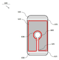
보다 구체적인 예로서, 도 1에서 볼 수 있는 바와 같이, 수신 디바이스(30)에는 임피던스 매칭 유닛(Impedance matching unit)이 포함될 수 있다. 이때, 상기 수신 디바이스(30)에 구비되는 임피던스 매칭 유닛은 최대 전력 전달을 위하여 임피던스 ZL 에 대한 임피던스 매칭 효과를 얻기 위하여 수신 코일(Rx Coil)로부터 송신 쪽으로 바라보는 임피던스(Zrx)와 공액 정합(conjugate matching) 조건이 성립되도록 한다. 이때, 상기 임피던스 ZL은 정류회로, DC-DC변환기, 배터리, 저항 또는 전기기기 등과 같은 부하를 포함한 등가 임피던스일 수 있다. 또한, 도 2에서는 본 발명의 일 실시예에 따른 무선 전력 수신 디바이스(200)에서의 무선 전력 수신 코일(202)의 장착 구조를 설명하기 위한 도면을 예시하고 있다.As a more specific example, as can be seen in FIG. 1, the receiving
본 발명의 일 실시예에 따른 무선 전력 수신 디바이스(200)에는 도 2에서 볼 수 있는 바와 같이 수신 코일(202)이 메탈 바디(204) 내부에 배치될 수 있다. 즉, 수신 코일(202)이 메탈 바디(204) 하면으로부터 이격되어 배치되는 것이 아니라 메탈 바디(204)의 홀(205)에 위치하거나 또는 상기 메탈 바디(204)에 내장되어 배치될 수 있다. 나아가, 상기 수신 코일(202)는 상기 메탈 바디(204)에 접촉하거나 가까운 위치에 배치될 수 있으며, 이에 따라 수신 코일(202)에서 발생하는 열을 효과적으로 배출할 수 있다. 따라서, 수신 코일(202)의 배치 구조를 최적화할 수 있고 발열 문제를 해결할 수 있다. 또한, 수신 코일(202)이 메탈 바디(204)에 밀착된 형태로 장착이 가능하므로, 송수신 사이의 거리를 단축할 수 있어 상호 인덕턴스를 증가시킬 수 있으므로 전력 전송 효율도 높아질 수 있다. The receiving
또한, 본 발명의 일 실시예에 따른 무선 전력 수신 디바이스(200)에서 상기 수신 코일(202)을 외부로부터 차폐하는 구조물이 포함될 수 있다. 보다 구체적인 예로서, 상기 구조물로서 플라스틱 로고(203)가 사용될 수 있고, 이때 상기 플라스틱 로고(203)는 플라스틱 필름 형태로 구성될 수도 있으며, 수신 코일(202)은 리드 프레임 패턴 코일(Lead Frame Pattern Coil)로 형성될 수 있으나, 이에 한정되지는 않으며, 본 발명의 다른 일 실시예에 따른 수신 코일(202)은, 리츠 와이어 코일, 금속선 코일, 동판 에칭 코일, PCB(Printed Circuit Board) 패턴 코일, FPCB(Flexible Printed Circuit Board) 등이 사용될 수도 있다.In addition, a structure for shielding the receiving
일 예로, 무선 전력 수신 디바이스(200)는 해당 디바이스 본체의 후면 일측에 형성된 홀을 통해 외부 노출되는 로고를 표시하기 위한 플라스틱 필름(Plastic Film), 플라스틱 필름 일면에 장착되는 리드 프레임 패턴 코일(Lead Frame Pattern Coil), 리드 프레임 패턴 코일 일면에 장착되는 마그네틱 쉬트(Magnetic Sheet)가 적층되어 구성될 수도 있다.For example, the wireless
도 2를 참조하면, 무선 전력 송신 디바이스(400)의 송신 코일(402)은 전원 소스(source)와 송신 코일(402)을 포함하여 구성될 수 있다. Referring to FIG. 2, the transmit
송신 코일(402)을 통해 송출되는 AC 전력-즉, 자기장-은 무선 전력 수신 디바이스(200)의 메탈 바디(204) 일측에 장착된 플라스틱 로고를 통해 수신 코일(202)에 전달될 수 있다. 하지만, 메탈 바디(204)의 표면 영역에는 자성체의 자속 변화에 따라 메탈 바디(204)에 와류 전류(eddy current)가 발생될 수 있다. 생성된 와류 전류는 송신 코일(402)에서 생성된 자기장을 상쇄시켜 송신 코일(402) 및 수신 코일(202) 간의 결합 효율을 떨어뜨리며, 송신 코일(402)의 손실 저항과 자기 인덕턴스를 변화시켜 공진 주파수가 틀어져 송신디바이스(400)에서 공진을 위한 튜닝 과정이 필요할 수 있다. 또한, 와류 전류에 의한 전력 손실은 열로 변환되어 무선 전력 수신 디바이스(200)의 메탈 바디(204)의 로고 홀(205) 주변 영역의 온도를 상승시킬 수 있다. 무선 전력 수신 디바이스(200)의 온도 상승은 과열 감지에 의한 충전 중단을 야기시킬 수 있다. 또한, 무선 전력 수신 디바이스(200)의 온도 상승은 인접하고 있는 무선 전력 송신 디바이스(400)의 온도 상승을 야기할 수도 있다.The AC power - that is, the magnetic field - transmitted through the transmitting
송신 코일(402)의 크기가 메탈 바디(204)의 크기보다 작거나 메탈 바디(204)의 홀(205)의 중심과 송신 코일(402)의 중심이 일치하였을 때, 송신 코일(402)의 크기는 송신 코일(402)의 최외각 와이어와 메탈 바디(204)의 테두리가 겹쳐지지 않도록 결정될 수 있다. 이는 송신 코일(402)에 의해 메탈 바디(204)의 최 외각 부분에서 역방향 전류가 유도되는데, 이 전류가 송신 코일(402)에서 생성되는 자기장을 상쇄시키는 역할을 하기 때문에 홀(205) 주변으로 흐르는 전류가 감소되기 때문이다. 그러나, 메탈 바디(204)가 개구의 크기 보다 150% 이상이 될 경우, 송신 코일(402)의 크기는 메탈 바디보다 클 수 있다. When the size of the
홀(205)의 크기는 송신 코일(402)에서 생성된 자기장 전체의 10~50% 가 직접 수신 코일(202)로 전달될 수 있도록 하는 크기가 적절하다. 메탈 바디(204)의 크기는 송신 코일(402)에서 생성된 자기장 전체의 75% 이상이 인가될 수 있도록 하는 크기가 적절하다.The size of the
도 3은 본 발명의 일 실시예에 따른 무선 전력 수신 디바이스(500)의 구조 및 특성을 설명하기 위한 도면이다.3 is a view for explaining the structure and characteristics of a wireless
본 실시예에 따른 무선 전력 수신 디바이스(500)는 메탈 바디를 가지는 스마트폰일 수 있으나 이에 한정되지는 않는다. The wireless
도 3을 참조하면, 무선 전력 수신 디바이스(500)의 후면은 크게 상단 바디(510), 중단 바디(520) 및 하단 바디(530) 중 적어도 하나를 포함하여 구성될 수 있다. 여기서, 상단 바디(510), 중단 바디(520) 및 하단 바디(530) 중 적어도 하나는 메탈 바디로 구성될 수 있다.Referring to FIG. 3, the rear surface of the wireless
도 3에 도시된 바와 같이, 중단 바디(520)와 상단 바디(510) 또는 하단 바디(530) 사이에는 이동 통신 안테나, 카메라 모듈, 스피커 등의 설계를 위한 슬릿(Slit, 515 및 525)이 구성되어 서로 분리될 수 있다. 이하 설명의 편의를 위해, 중단 바디(520)와 상단 바디(510) 사이, 중단 바디(520)와 하단 바디(530) 사이에 형성되는 슬릿을 통칭하여 제2 개구부(515 및 525)라 명하기로 한다. 단, 중단 바디(520)와 상단 바디(510) 사이에 형성되는 슬릿과 중단 바디(520)와 하단 바디(530) 사이에 형성되는 슬릿을 구분하여 설명해야 하는 경우, 중단 바디(520)와 상단 바디(510) 사이에 형성되는 슬릿은 상단 제2 개구부(515), 중단 바디(520)와 하단 바디(530) 사이에 형성되는 슬릿은 하단 제2 개구부(525)라 명하기로 한다.
중단 바디(520)의 일측에는 홀(540)이 형성될 수 있으며, 홀(540)의 주변(메탈 바디의 하부)에는 수신 코일이 배치될 수 있다. 물론, 홀(540)의 내부에는 특정 로고가 인쇄된 플라스틱 필름이 부착되거나 비전도성 소재로 만들어진 부품이 홀(540)의 형태로 제작되어 홀(540) 내에 장착될 수 있다. 홀(540)은 중단 바디(520)의 정중앙에 위치한다고 가정한다. 홀(540)이 중단 바디(520)의 정중앙에 위치하였을 때, 송신 코일에 의한 충전 가능 영역 상에 홀(540)이 위치하기 용이해 진다. 따라서, 송신 코일에 의한 자기장을 직접 수신하는 홀(540)을 중단 바디(520)의 정중앙에 위치시키는 것이 충전 효율을 높일 수 있다.A
무선 전력 수신 디바이스(500)가 충전 영역에 위치되어 무선 충전이 개시되면, 홀(540) 주변의 메탈 바디 영역에 자기장이 인가되어 와류 전류-즉, 맴돌이 전류-가 유도될 수 있다. 제1 개구부(545)가 없이 홀(540) 주변만을 원형으로 흐르는 형태로 와류 전류가 발생되는 경우, 홀 주위에 흐르는 와류 전류는 송신 코일의 전류 방향과 반대 방향으로 흘러 홀로 입사되는 송신부 자기장의 세기를 크게 줄이기 때문에 무선 충전 효율이 저하될 뿐만 아니라 홀(540) 주변의 온도가 상승할 수 있다. 이는, 무선 전력 수신 디바이스뿐만 아니라 무선 전력 송신 장치에도 장애를 발생시켜 고장을 유발하거나 무선 충전이 비정상적으로 종료될 수 있다.When the wireless
무선 전력 수신 디바이스(500)는 제1 개구부(545)를 더 포함하여 구성될 수 있다. 여기서, 제1 개구부(545)를 통해 무선 전력 수신 디바이스(500)는 홀(540) 주변만을 원형으로 흐르는 와류 전류가 발생되는 것을 차단할 수 있다.The wireless
도 3을 참조하면, 제1 개구부(545)는 상단 제2 개구부(515)에 연접되고, 홀(540)의 외경과 연접되도록 구성될 수 있다. 다른 실시예에 따라 제1 개구부(545)는 하단 제2 개구부(525), 중단 바디(520)의 좌측 모서리, 또는 중단 바디(520)의 우측 모서리에 연접되고, 홀(540)의 외경과 연접되도록 구성될 수 있다.Referring to FIG. 3, the
또한, 제1 개구부(545)는 비전도성 소재로 구성될 수 있다. 일 예로, 비전도성 소재는 플라스틱 소재를 포함할 수 있으나, 이에 한정되지는 않는다. In addition, the
또한, 도 3에 도시된 바와 같이, 제1 개구부(545)의 폭이 홀(540)의 직경보다 작게 형성될 수 있다. 일 예로, 홀(540)의 직경이 13mm인 경우, 제1 개구부(545)의 폭은 5mm 이내로 형성될 수 있으나, 이에 한정되지는 않는다. 3, the width of the
제1 개구부(545)가 상단 제2 개구부(515) 및 홀(540)에 연접하여 형성됨으로써, 무선 전력 송신기가 송신하는 자기장 중 중단 바디(520)로 인가되는 자기장에 유도되는 유도 전류(550)가 도 3에 도시된 바와 같이 홀(540), 제1 개구부(545), 제2 개구부(515,525) 및 중단 바디(520)의 좌우 모서리를 따라 흐르게 된다. 유도 전류(550)의 방향은 일 실시예에 불과하며 본 발명의 범위는 이에 한정되지 않는다.The
각 영역에 흐르는 전류의 세기는 다를 수 있으나, 전류 세기는 불연속성 없이 연속적인 특성을 갖는다. 즉, 홀 주위에 흐르는 전류가 매우 작더라도, 메탈 바디 외각과 제 1 개구부를 따라 흐르는 전류는 클 수 있다. 그러나, 전류의 세기가 갑자기 작아지거나, 커지지는 않는다. The intensity of current flowing in each region may be different, but the current intensity has continuous characteristics without discontinuity. That is, even if the current flowing around the hole is very small, the current flowing along the outer periphery of the metal body and the first opening may be large. However, the intensity of the current does not suddenly decrease or increase.
특히, 홀 주위에 흐르는 와류 전류와 관련하여, 송신 코일의 크기, 송신 코일과 메탈 바디 사이의 간격을 조절하여 홀 주위에 인가되는 자기장의 세기를 조절하므로, 홀 주위에 흐르는 와류 전류를 매우 작게 할 수도 있으며, 나아가 홀 주위에 흐르는 와류 전류의 방향이 송신 코일의 전류 방향과 동일하게 흐르도록 할 수 있다. 예로 홀 주위에 흐르는 전류를 작게 하기 위해서는 메탈 바디에 인가되는 송신 코일의 50% 이상의 자기장이 홀 근처에 인가되거나, 또는 송신 코일의 최대 크기가 홀 크기의 150%이내의 경우이다. 그리고 송신 코일에 흐르는 전류와 동일한 방향의 와류 전류를 얻어, 결합 효율을 높이기 위해서는 송신 코일에서 만든 자기장이 홀 주위에 50% 이하가 입사되거나, 송신 코일의 크기가 메탈 바디만큼 클 때에 와류를 전류를 얻을 수 있다.Particularly, in relation to eddy currents flowing around the holes, the magnitude of the magnetic field applied around the holes is controlled by adjusting the size of the transmitting coil and the distance between the transmitting coil and the metal body, so that the eddy current flowing around the holes is made very small And further, the direction of the eddy current flowing around the hole can be made to flow in the same direction as the current direction of the transmitting coil. For example, in order to reduce the current flowing around the hole, a magnetic field of 50% or more of the transmitting coil applied to the metal body is applied near the hole, or the maximum size of the transmitting coil is within 150% of the hole size. In order to obtain a swirling current in the same direction as the current flowing in the transmission coil, in order to increase the coupling efficiency, a magnetic field created by the transmission coil is incident on the periphery of the hole of less than 50%, or when the transmission coil size is as large as the metal body, Can be obtained.
또한, 홀(540) 주변에만 흐르게 되는 와류 전류에 비해, 제1 개구부(545)가 형성됨에 의해 도 3에 도시된 바와 같이 와류 전류에 의한 유도 전류(550)가 더 길어진 경로를 통해 흐르도록 하여 열 발생이 분산되도록 할 수 있다.In addition, since the
한편, 중단 바디(520)로 인가된 자기장이 송신 코일의 전류 방향과 동일한 방향의 와류 전류, 즉, 유도 전류(550) 생성에 기여함에 의해, 이 생성된 유도 전류(550)의 세기는 상기 와류 전류의 세기에 비해 더 클 수 있다. 이러한 유도 전류(550)는 자기장을 발생하여 중단 바디(520) 하부의 수신 코일에 유도 전류가 흐르도록 할 수 있다. 즉, 무선 전력 송신기에 의해 발생된 자기장 중 중단 바디(520)에 직접 전달된 전력이 열로 손실되는 것이 아니라, 유도 전류(550)를 통해 수신 코일로 전달될 수 있다.On the other hand, since the magnetic field applied to the suspended
도 4는 본 발명의 다른 실시예에 따른 무선 전력 수신 디바이스의 구조 및 특성을 설명하기 위한 도면이다.4 is a view for explaining the structure and characteristics of a wireless power receiving device according to another embodiment of the present invention.
도 4를 참조하면, 무선 전력 수신 디바이스(600)의 구조는 달리 설명되지 않는 한 도 3의 무선 전력 수신 디바이스(500)의 구조와 다르지 않으므로 중복되는 설명은 생략하기로 한다.Referring to FIG. 4, the structure of the wireless
제1 개구부(645)는 하단 제2 개구부(625)에 연접되고, 홀(640)의 외경과 연접되도록 구성될 수 있다. 다른 실시예에 따라 제1 개구부(645)는 상단 제2 개구부(615), 중단 바디(620)의 좌측 모서리, 또는 중단 바디(620)의 우측 모서리에 연접되고, 홀(640)의 외경과 연접되도록 구성될 수 있다.The
제1 개구부(645)가 하단 제2 개구부(625) 및 홀(640)에 연접하여 형성됨으로써, 무선 전력 송신기가 송신하는 자기장 중 중단 바디(620)로 흡수되는 자기장에 유도되는 유도 전류(650)가 도 6에 도시된 바와 같이 홀(640), 제1 개구부(645), 제2 개구부(615,625) 및 중단 바디(620)의 좌우 모서리를 따라 흐르게 된다. 유도 전류(650)의 방향은 일 실시예에 불과하며 본 발명의 범위는 이에 한정되지 않는다.The
홀(640) 주변에만 원형으로 흐르게 되는 와류 전류에 비해, 제1 개구부(645)가 형성됨에 의해 도 4에 도시된 바와 같이 와류 전류에 의해 유도되는 유도 전류(650)가 더 길어진 경로를 통해 흐르도록 하여 열 발생이 분산되도록 할 수 있다.The induction current 650 induced by the eddy current flows through the longer path as shown in FIG. 4 due to the formation of the
또한, 송신 코일의 자기장이 중단 바디(620)에 인가되면, 인가된 자기장의 일부는 홀(640) 주위에서 송신 코일의 전류 방향과 동일한 방향으로 흐르는 전류가 재유도되어 수신 코일에 더욱 큰 자기 결합효율을 갖도록 한다. 즉, 무선 전력 송신기에 의해 발생된 자기장 중 중단 바디(620)에 직접 전달된 전력이 열로 손실되는 것이 아니라, 유도 전류(650)를 통해 수신 코일로 전달될 수 있다.When a magnetic field of the transmitting coil is applied to the suspended
도 5는 도 3에 도시된 무선 전력 수신 디바이스에 포함되는 수신 코일의 일 실시예를 설명하기 위한 도면이다.5 is a view for explaining an embodiment of a receiving coil included in the wireless power receiving device shown in FIG.
도 5를 참조하면, 도 5에 도시된 무선 전력 수신 디바이스(700)는 도 3의 무선 전력 수신 디바이스(500)의 뒷면(장치 안쪽에서 바라본 면)의 일 실시예를 나타낸다. Referring to FIG. 5, the wireless
수신 코일(710)은 홀(540)의 외경을 따라 원형으로 감긴 형태를 가질 수 있다. 따라서, 수신 코일(710)의 내경은 가장 안쪽 코일의 지름이 되고, 수신 코일(710)의 외경은 가장 바깥쪽 코일의 지름이 된다.The receiving
수신 코일(710)의 외경(D2)은 홀(540)의 외경(D1)보다 클 수 있고, 수신 코일(710)의 내경 역시 홀(540)의 외경(D1)보다 클 수 있다. 이는 개구에서 큰 유도 전류가 만들어져, 여러 턴으로 구성된 수신 코일에서 최대의 효율을 얻을 수 있다.The outer diameter D2 of the receiving
다른 실시예에 따라, 수신 코일(710)의 외경(D2)은 홀(540)의 외경(D1)보다 클 수 있고, 수신 코일(710)의 내경은 홀(540)의 외경(D1)보다 작을 수 있다. 이 경우는 홀이 상대적으로 크고, 홀에 흐르는 와류 전류가 작을 경우에 적합하다.The outer diameter D2 of the receiving
무선 전력 송신기가 송신하는 자기장은 홀(540)을 직접 통과하여 수신 코일(710)로 전달되는 자기장과, 중단 바디(520)에 인가되어 발생된 유도 전류(550)를 통해 전달되는 자기장으로 나뉠 수 있다.The magnetic field transmitted by the wireless power transmitter can be divided into a magnetic field that passes directly through the
홀(540)을 직접 통과하여 수신 코일(710)로 전달되는 자기장과, 중단 바디(520)에 흐르는 유도 전류(550) 중 홀(540)의 외경을 따라 흐르는 유도 전류(550)에 의한 자기장은 서로 중첩되어 증폭될 수 있다.The magnetic field generated by the magnetic field transmitted directly to the receiving
이에 반해, 홀(540)을 직접 통과하여 수신 코일(710)로 전달되는 자기장과, 중단 바디(520)에 흐르는 유도 전류(550) 중 제2 개구부(515,525) 및 중단 바디(520)의 좌우 모서리를 따라 흐르는 유도 전류(550)에 의한 자기장은 서로 상쇄될 수 있다. 이는 홀(540)의 외경을 따라 흐르는 유도 전류(550)와 제2 개구부(515,525) 및 중단 바디(520)의 좌우 모서리를 따라 흐르는 유도 전류(550)는 서로 반대 방향으로 흐르며, 각 유도 전류에 따른 자기장 역시 서로 반대의 방향을 갖기 때문이다.The magnetic field transmitted directly to the receiving
그리고, 수신 코일(710)이 도 5에 도시된 바와 같이 홀(540)을 따라 감긴 형태를 가지게 되면, 보다 높은 무선 전력 수신 효율을 가질 수 있다. 이는 홀 주위에 와류 전류의 세기를 크게 낮추어, 송신 코일에 의한 자기장을 감쇄없이 모두 수신할 수 있기 때문이다. 특히, 홀 주위에 송신 코일과 동일한 방향의 와류 전류를 생성할 수 있어, 홀을 직접 통과하는 자기장과 와류전류에 의한 자기장이 중첩된 수신 효율을 크게 증가시킬 수 있다. 즉, 수신 코일(710)이 홀(540)을 따라 감긴 형태를 가짐에 따라, 홀(540)을 직접 통과하여 수신 코일(710)로 전달되는 자기장과 홀(540)의 외경을 흐르는 유도 전류(550)에 의한 자기장을 최대로 흡수하여 강한 유도 전류를 발생시킬 수 있고, 이에 따라 높은 무선 전력 수신 효율을 가질 수 있다.When the receiving
도 6은 도 4에 도시된 무선 전력 수신 디바이스에 포함되는 수신 코일의 일 실시예를 설명하기 위한 도면이다.6 is a view for explaining an embodiment of a receiving coil included in the wireless power receiving device shown in FIG.
도 6을 참조하면, 도 6에 도시된 무선 전력 수신 디바이스(800)는 도 4의 무선 전력 수신 디바이스(600)의 뒷면(장치 안쪽에서 바라본 면)의 일 실시예를 나타낸다. Referring to FIG. 6, the wireless
수신 코일(810)은 홀(640)의 외경을 따라 원형으로 감긴 형태를 가질 수 있다. 따라서, 수신 코일(810)의 내경은 가장 안쪽 코일의 지름이 되고, 수신 코일(810)의 외경은 가장 바깥쪽 코일의 지름이 된다.The receiving
수신 코일(810)의 외경(D4)은 홀(640)의 외경(D1)보다 클 수 있고, 수신 코일(810)의 내경 역시 홀(640)의 외경(D1)보다 클 수 있다.The outer diameter D4 of the receiving
다른 실시예에 따라, 수신 코일(810)의 외경(D2)은 홀(640)의 외경(D1)보다 클 수 있고, 수신 코일(810)의 내경은 홀(640)의 외경(D1)보다 작을 수 있다.The outer diameter D2 of the receiving
무선 전력 송신기가 송신하는 자기장은 홀(640)을 직접 통과하여 수신 코일(810)로 전달되는 자기장과, 중단 바디(620)에 흡수되어 발생된 유도 전류(550)를 통해 전달되는 자기장으로 나뉠 수 있다.The magnetic field transmitted by the wireless power transmitter can be divided into a magnetic field that passes directly through the
홀(640)을 직접 통과하여 수신 코일(810)로 전달되는 자기장과, 중단 바디(620)에 흐르는 유도 전류(650) 중 홀(640)을 흐르는 유도 전류(650)에 의한 자기장은 서로 중첩되어 증폭될 수 있다.The magnetic field transmitted directly through the
이에 반해, 홀(640)을 직접 통과하여 수신 코일(810)로 전달되는 자기장과, 중단 바디(620)에 흐르는 유도 전류(650) 중 제2 개구부(615,625) 및 중단 바디(620)의 좌우 모서리를 따라 흐르는 유도 전류(650)에 의한 자기장은 서로 상쇄될 수 있다. 이는 홀(640)을 흐르는 유도 전류(650)와 제2 개구부(615,625) 및 중단 바디(620)의 좌우 모서리를 따라 흐르는 유도 전류(650)는 서로 반대 방향으로 흐르며, 각 유도 전류에 따른 자기장 역시 서로 반대의 방향을 갖기 때문이다.The magnetic field transmitted directly to the receiving
그리고, 수신 코일(810)이 도 6에 도시된 바와 같이 홀(640)을 따라 감긴 형태를 가지게 되면, 보다 높은 무선 전력 수신 효율을 가질 수 있다. 이는 중단 바디(620)에 흐르는 유도 전류(650) 중 홀(640)을 흐르는 유도 전류(650)에 의한 자기장이 제1 개구부(645)를 흐르는 유도 전류(650)에 의한 자기장보다 자속 밀도가 현저히 높기 때문이다.If the receiving
즉, 수신 코일(810)이 홀(640)을 따라 감긴 형태를 가짐에 따라, 홀(640)을 직접 통과하여 수신 코일(810)로 전달되는 자기장과 홀(640)을 흐르는 유도 전류(650)에 의한 자기장을 최대로 흡수하여 강한 유도 전류를 발생시킬 수 있고, 이에 따라 높은 무선 전력 수신 효율을 가질 수 있다.That is, since the receiving
도 7은 도 3에 도시된 무선 전력 수신 디바이스에 포함되는 수신 코일의 다른 실시예를 설명하기 위한 도면이다.7 is a view for explaining another embodiment of the receiving coil included in the wireless power receiving device shown in FIG.
도 7을 참조하면, 도 7에 도시된 무선 전력 수신 디바이스(900)는 도 3의 무선 전력 수신 디바이스(500)의 뒷면(장치 안쪽에서 바라본 면)의 다른 실시예를 나타낸다. Referring to Fig. 7, the wireless
수신 코일(910)은 도 5에 도시된 수신 코일(710)과 마찬가지로 홀(540)의 외경을 따라 감긴 형태를 가질 수 있다. 그러나, 수신 코일(910)의 형태는 다양한 이유로(예컨대, 메탈 바디의 하부 설계 구조 등) 변형되어 제작될 수 있다.The receiving
예를 들어, 수신 코일(910)은 도 5의 수신 코일(710)보다 더 큰 외경과 내경을 가질 수 있고, 원형이 아닌 타원 형태를 가질 수 있다.For example, the receiving
도 5에서 설명한 바와 같이, 홀(540)을 직접 통과하여 수신 코일(910)로 전달되는 자기장과, 중단 바디(520)에 흐르는 유도 전류(550) 중 홀(540)의 외경을 따라 흐르는 유도 전류(550)에 의한 자기장은 서로 중첩되어 증폭될 수 있다.5, a magnetic field passing directly through the
이에 반해, 홀(540)을 직접 통과하여 수신 코일(710)로 전달되는 자기장 및 홀(540)의 외경을 따라 흐르는 유도 전류(550)에 의한 자기장과, 제2 개구부(515,525) 및 중단 바디(520)의 좌우 모서리를 따라 흐르는 유도 전류(550)에 의한 자기장은 서로 상쇄된다. On the other hand, the magnetic field generated by the induction current 550 flowing through the
따라서, 높은 무선 전력 수신 효율을 위해, 수신 코일(910)에 대해 일정한 설계 조건이 요구된다.Therefore, for the high wireless power receiving efficiency, a certain design condition is required for the receiving
도 7을 참조하면, 상단 제2 개구부(515)와 홀(540)의 최상단 사이의 거리를 제1 높이(H1)라 하고, 제1 높이(H1)의 1/2을 제2 높이(H2)라 하면, 상단 제2 개구부(515)로부터 제2 높이(H2)만큼 떨어진 선을 제1 라인(L1)이라 할 수 있다. 7, a distance between the upper
마찬가지로, 하단 제2 개구부(525)와 홀(540)의 최하단 사이의 거리를 제3 높이(H3)라 하고, 제3 높이(H3)의 1/2을 제4 높이(H4)라 하면, 하단 제2 개구부(525)로부터 제4 높이(H4)만큼 떨어진 선을 제2 라인(L2)이라 할 수 있다.Similarly, when the distance between the lower
만일, 수신 코일(910)의 상부 외경(코일의 최상단)이 제1 라인(L1)을 넘어서 상단 제2 개구부(515)에 근접하게 되거나, 수신 코일(910)의 하부 외경(코일의 최하단)이 제2 라인(L2)을 넘어서 하단 제2 개구부(525)에 근접하게 되면, 수신 코일(910)은 홀(540)의 외경을 따라 흐르는 유도 전류(550)에 의한 자기장을 흡수하기 어려울 뿐 아니라 제2 개구부(515,525)를 따라 흐르는 유도 전류(550)에 의한 자기장의 영향을 받아 무선 전력 수신 효율이 급격히 저하될 수 있다.If the upper outer diameter of the receiving coil 910 (the upper end of the coil) approaches the upper
따라서, 수신 코일(910)은 제1 라인(L1)과 제2 라인(L2) 사이에 배치됨이 바람직 하다.Therefore, it is preferable that the receiving
중단 바디(520)의 좌측 모서리와 홀(540)의 좌측끝 사이의 거리를 제1 폭(W1)이라 하고, 제1 폭(W1)의 1/2을 제2 폭(W2)이라 하면, 중단 바디(520)의 좌측 모서리로부터 제2 폭(W2)만큼 떨어진 선을 제3 라인(L3)이라 할 수 있다. If the distance between the left edge of the suspended
마찬가지로, 중단 바디(520)의 우측 모서리와 홀(540)의 우측끝 사이의 거리를 제3 폭(W3)이라 하고, 제3 폭(W3)의 1/2을 제4 폭(W4)이라 하면, 중단 바디(520)의 우측 모서리로부터 제4 폭(W4)만큼 떨어진 선을 제4 라인(L4)이라 할 수 있다.Similarly, if the distance between the right edge of the suspended
만일, 수신 코일(910)의 좌측 외경(코일의 좌측끝)이 제3 라인(L3)을 넘어서 중단 바디(520)의 좌측 모서리에 근접하게 되거나, 수신 코일(910)의 우측 외경(코일의 우측끝)이 제4 라인(L4)을 넘어서 중단 바디(520)의 우측 모서리에 근접하게 되면, 수신 코일(910)은 홀(540)의 외경을 따라 흐르는 유도 전류(550)에 의한 자기장을 흡수하기 어려울 뿐 아니라 중단 바디(520)의 좌측/우측 모서리를 따라 흐르는 유도 전류(550)에 의한 자기장의 영향을 받아 무선 전력 수신 효율이 급격히 저하될 수 있다.If the left outer diameter of the receiving coil 910 (the left end of the coil) exceeds the third line L3 and approaches the left edge of the stopped
따라서, 수신 코일(910)은 제3 라인(L3)과 제4 라인(L4) 사이에 배치됨이 바람직 하다.Therefore, it is preferable that the receiving
제1 라인(L1)과 제2 라인(L2) 사이 및 제3 라인(L3)과 제4 라인(L4) 사이로 구획되는 영역은 제1 영역(A1)으로 정의될 수 있다. 즉, 수신 코일(910)은 제1 영역(A1)의 내부에 배치되어, 제2 개구부(515,525) 및 중단 바디(520)의 좌우 모서리를 따라 흐르는 유도 전류(550)에 의한 자기장의 영향을 최소화하면서, 홀(540)을 직접 통과하여 수신 코일(710)로 전달되는 자기장 및 홀(540)의 외경을 따라 흐르는 유도 전류(550)에 의한 자기장을 흡수하여 무선 전력 수신 효율을 높일 수 있다.A region defined between the first line L1 and the second line L2 and between the third line L3 and the fourth line L4 may be defined as the first area A1. That is, the receiving
도 7의 예에서는 제1 영역(A1)을 결정하는 기준이 특정 비율(예컨대, 제1 라인(L1)이 제1 높이(H1)의 50%인 제2 높이(H2)로 결정)로 설명되었으나, 본 발명의 범위는 이에 한정되지 않는다. 예를 들어, 무선 전력 수신 디바이스(900)의 구조, 홀(540)의 크기, 수신 코일(910)의 인덕턴스 등에 따라 상기 특정 비율은 달리 결정될 수 있다. 또한, 제1 라인(L1) 내지 제4 라인(L4) 각각이 결정되는 비율은 각기 달리 설정될 수도 있다.In the example of FIG. 7, the criterion for determining the first area A1 has been described as a certain ratio (for example, the first line L1 is determined as the second height H2, which is 50% of the first height H1) , The scope of the present invention is not limited thereto. For example, the specific ratio may be determined differently depending on the structure of the wireless
본 발명의 실시예에 따른 무선 전력 수신 디바이스에 의하면, 메탈 바디의 영향에 의한 무선 전력 전송 효율의 감소를 최소화시키고, 메탈 바디에 자기장이 흡수됨에 의해 발생하는 발열을 최소화시키는 것이 가능하다.According to the wireless power receiving device according to the embodiment of the present invention, it is possible to minimize the reduction of the wireless power transmission efficiency due to the influence of the metal body and to minimize the heat generated by the absorption of the magnetic field in the metal body.
도 8은 도 4에 도시된 무선 전력 수신 디바이스에 포함되는 수신 코일의 다른 실시예를 설명하기 위한 도면이다.FIG. 8 is a view for explaining another embodiment of the receiving coil included in the wireless power receiving device shown in FIG.
도 8을 참조하면, 도 8에 도시된 무선 전력 수신 디바이스(1000)는 도 4의 무선 전력 수신 디바이스(600)의 뒷면(장치 안쪽에서 바라본 면)의 다른 실시예를 나타낸다. Referring to Fig. 8, the wireless
수신 코일(1010)은 도 6에 도시된 수신 코일(810)과 마찬가지로 홀(640)의 외경을 따라 감긴 형태를 가질 수 있다. 그러나, 수신 코일(1010)의 형태는 다양한 이유로(예컨대, 메탈 바디의 하부 설계 구조 등) 변형되어 제작될 수 있다.The receiving
예를 들어, 수신 코일(1010)은 도 6의 수신 코일(810)보다 더 큰 외경과 내경을 가질 수 있고, 원형이 아닌 타원 형태를 가질 수 있다.For example, the receive
도 6에서 설명한 바와 같이, 홀(640)을 직접 통과하여 수신 코일(1010)로 전달되는 자기장과, 중단 바디(620)에 흐르는 유도 전류(650) 중 홀(640)의 외경을 따라 흐르는 유도 전류(650)에 의한 자기장은 서로 중첩되어 증폭될 수 있다.The magnetic field transmitted directly to the receiving
이에 반해, 홀(640)을 직접 통과하여 수신 코일(810)로 전달되는 자기장 및 홀(640)의 외경을 따라 흐르는 유도 전류(650)에 의한 자기장과, 제2 개구부(615,625) 및 중단 바디(620)의 좌우 모서리를 따라 흐르는 유도 전류(650)에 의한 자기장은 서로 상쇄된다. The magnetic field generated by the induction current 650 flowing through the
따라서, 높은 무선 전력 수신 효율을 위해, 수신 코일(1010)에 대해 일정한 설계 조건이 요구된다.Therefore, for the high wireless power receiving efficiency, a certain design condition is required for the receiving
도 8을 참조하면, 상단 제2 개구부(615)와 홀(640)의 최상단 사이의 거리를 제5 높이(H5)라 하고, 제5 높이(H5)의 1/2을 제6 높이(H6)라 하면, 상단 제2 개구부(615)로부터 제6 높이(H6)만큼 떨어진 선을 제5 라인(L5)이라 할 수 있다. 8, the distance between the upper
마찬가지로, 하단 제2 개구부(625)와 홀(640)의 최하단 사이의 거리를 제7 높이(H7)라 하고, 제7 높이(H7)의 1/2을 제8 높이(H8)라 하면, 하단 제2 개구부(625)로부터 제8 높이(H8)만큼 떨어진 선을 제6 라인(L6)이라 할 수 있다.Similarly, assuming that a distance between the lower
만일, 수신 코일(1010)의 상부 외경(코일의 최상단)이 제5 라인(L5)을 넘어서 상단 제2 개구부(615)에 근접하게 되거나, 수신 코일(1010)의 하부 외경(코일의 최하단)이 제6 라인(L6)을 넘어서 하단 제2 개구부(625)에 근접하게 되면, 수신 코일(1010)은 홀(640)의 외경을 따라 흐르는 유도 전류(650)에 의한 자기장을 흡수하기 어려울 뿐 아니라 제2 개구부(615,625)를 따라 흐르는 유도 전류(650)에 의한 자기장의 영향을 받아 무선 전력 수신 효율이 급격히 저하될 수 있다.If the upper outer diameter of the receiving coil 1010 (the upper end of the coil) is closer to the upper
따라서, 수신 코일(1010)은 제5 라인(L5)과 제6 라인(L6) 사이에 배치됨이 바람직하다.Therefore, it is preferable that the receiving
중단 바디(620)의 좌측 모서리와 홀(640)의 좌측끝 사이의 거리를 제5 폭(W5)이라 하고, 제5 폭(W5)의 1/2을 제6 폭(W6)이라 하면, 중단 바디(620)의 좌측 모서리로부터 제6 폭(W6)만큼 떨어진 선을 제7 라인(L7)이라 할 수 있다. The distance between the left edge of the suspended
마찬가지로, 중단 바디(620)의 우측 모서리와 홀(640)의 우측끝 사이의 거리를 제7 폭(W7)이라 하고, 제7 폭(W7)의 1/2을 제8 폭(W8)이라 하면, 중단 바디(620)의 우측 모서리로부터 제8 폭(W8)만큼 떨어진 선을 제8 라인(L8)이라 할 수 있다.Similarly, the distance between the right edge of the suspended
만일, 수신 코일(1010)의 좌측 외경(코일의 좌측끝)이 제7 라인(L7)을 넘어서 중단 바디(620)의 좌측 모서리에 근접하게 되거나, 수신 코일(1010)의 우측 외경(코일의 우측끝)이 제8 라인(L8)을 넘어서 중단 바디(620)의 우측 모서리에 근접하게 되면, 수신 코일(1010)은 홀(640)의 외경을 따라 흐르는 유도 전류(650)에 의한 자기장을 흡수하기 어려울 뿐 아니라 중단 바디(620)의 좌측/우측 모서리를 따라 흐르는 유도 전류(650)에 의한 자기장의 영향을 받아 무선 전력 수신 효율이 급격히 저하될 수 있다.If the left outer diameter of the receiving coil 1010 (the left end of the coil) exceeds the seventh line L7 and approaches the left edge of the stopped
따라서, 수신 코일(1010)은 제7 라인(L7)과 제8 라인(L8) 사이에 배치됨이 바람직하다.Therefore, it is preferable that the receiving
제5 라인(L5)과 제6 라인(L6) 사이 및 제7 라인(L7)과 제8 라인(L8) 사이로 구획되는 영역은 제2 영역(A2)으로 정의될 수 있다. 즉, 수신 코일(1010)은 제2 영역(A2)의 내부에 배치되어, 제2 개구부(615,625) 및 중단 바디(620)의 좌우 모서리를 따라 흐르는 유도 전류(650)에 의한 자기장의 영향을 최소화하면서, 홀(640)을 직접 통과하여 수신 코일(810)로 전달되는 자기장 및 홀(640)의 외경을 따라 흐르는 유도 전류(650)에 의한 자기장을 흡수하여 무선 전력 수신 효율을 높일 수 있다.A region defined between the fifth line L5 and the sixth line L6 and between the seventh line L7 and the eighth line L8 may be defined as the second region A2. That is, the receiving
도 8의 예에서는 제2 영역(A2)을 결정하는 기준이 특정 비율(예컨대, 제5 라인(L5)이 제5 높이(H5)의 50%인 제6 높이(H6)로 결정)로 설명되었으나, 본 발명의 범위는 이에 한정되지 않는다. 예를 들어, 무선 전력 수신 디바이스(1000)의 구조, 홀(640)의 크기, 수신 코일(1010)의 인덕턴스 등에 따라 상기 특정 비율은 달리 결정될 수 있다. 또한, 제5 라인(L5) 내지 제8 라인(L8) 각각이 결정되는 비율은 각기 달리 설정될 수도 있다.In the example of Fig. 8, the criterion for determining the second area A2 is a specific ratio (for example, the fifth line L5 is determined as the sixth height H6, which is 50% of the fifth height H5) , The scope of the present invention is not limited thereto. For example, the specific ratio may be determined differently depending on the structure of the wireless
본 발명의 실시예에 따른 무선 전력 수신 디바이스에 의하면, 메탈 바디의 영향에 의한 무선 전력 전송 효율의 감소를 최소화시키고, 메탈 바디에 자기장이 흡수됨에 의해 발생하는 발열을 최소화시키는 것이 가능하다.According to the wireless power receiving device according to the embodiment of the present invention, it is possible to minimize the reduction of the wireless power transmission efficiency due to the influence of the metal body and to minimize the heat generated by the absorption of the magnetic field in the metal body.
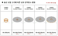
도 9는 무선 전력 송신기의 송신 코일의 크기에 따른 상호 인덕턴스의 변화를 설명하기 위한 도면이다. 9 is a diagram for explaining a change in mutual inductance according to the size of a transmission coil of a wireless power transmitter.
도 9를 참조하면, 제1 케이스(CASE1)는 무선 전력 수신 코일이 다른 구성의 영향을 받지 않고 공기 중에서 무선 전력 송신 코일로부터 전력을 수신하는 경우를 의미한다. 도 9에서 상측에 위치한 코일은 무선 전력 수신 코일이고, 하측에 위치한 코일은 무선 전력 송신 코일이다.Referring to FIG. 9, the first case CASE1 denotes a case where the wireless power receiving coil receives power from the wireless power transmission coil in the air without being affected by other configurations. In FIG. 9, the coil located on the upper side is a wireless power receiving coil, and the coil positioned on the lower side is a wireless power transmitting coil.
여기서, 무선 전력 송신 코일은 30(mm)의 외경(Tx_Dout=30mm), 6번의 감은수 및 0.3(mm)의 폭을 가지고, 무선 전력 수신 코일은 30(mm)의 외경(Rx_Dout=30mm), 6번의 감은수 및 0.3(mm)의 폭을 가지며, 무선 전력 송신 코일과 무선 전력 수신 코일 사이의 거리는 10(mm)로 설정된다.The wireless power transmission coil has an outer diameter (Rx_Dout = 30 mm) of 30 (mm), an outer diameter of 30 mm (Rx_Dout = 30 mm) And a width of 0.3 (mm), and a distance between the wireless power transmission coil and the wireless power reception coil is set to 10 (mm).
제2 케이스(CASE2)는 무선 전력 송신 코일과 무선 전력 수신 코일 사이에 중앙의 홀을 포함하는 메탈 케이스(metal case)가 구비되어 무선 전력 송신 코일로부터 전력을 수신하는 경우를 의미한다.The second case (CASE2) means a case where a metal case including a central hole is provided between the wireless power transmission coil and the wireless power reception coil to receive power from the wireless power transmission coil.
여기서, 메탈 케이스는 150(mm)의 외경을 가지고, 메탈 케이스의 홀은 13(mm)의 외경을 가지도록 설정되고, 무선 전력 송신 코일과 무선 전력 수신 코일은 제1 케이스(CASE1)과 동일하게 설정된다. 또한, 메탈 케이스는 일측에 제1 개구부를 포함할 수 있다.The metal case has an outer diameter of 150 mm and the metal case hole has an outer diameter of 13 mm. The wireless power transmission coil and the wireless power reception coil are the same as the first case CASE 1 Respectively. Further, the metal case may include a first opening on one side.
제3 케이스(CASE3)는 제2 케이스(CASE2)와 동일한 조건에서 무선 전력 수신 코일이 외경이 60mm인 무선 전력 송신 코일로부터 전력을 수신하는 경우를 의미한다. The third case (CASE3) means that the wireless power receiving coil receives power from a wireless power transmission coil having an outer diameter of 60 mm under the same condition as the second case (CASE2).
제4 케이스(CASE4)는 제2 케이스(CASE2)와 동일한 조건에서 무선 전력 수신 코일이 외경이 90mm인 무선 전력 송신 코일로부터 전력을 수신하는 경우를 의미한다.The fourth case (CASE4) means that the wireless power receiving coil receives power from a wireless power transmission coil having an outer diameter of 90 mm under the same condition as the second case (CASE2).
제5 케이스(CASE5)는 제2 케이스(CASE2)와 동일한 조건에서 무선 전력 수신 코일이 외경이 150mm인 무선 전력 송신 코일로부터 전력을 수신하는 경우를 의미한다.The fifth case (CASE5) means that the wireless power receiving coil receives power from a wireless power transmission coil having an outer diameter of 150 mm under the same condition as the second case (CASE2).
도 9에는 각 케이스 별로 위와 같은 조건에서 3D 시뮬레이션을 수행하여 무선 전력 수신 코일과 무선 전력 송신 코일 간의 상호 인덕턴스(M)를 산출한 결과가 나타나 있다. 무선 전력 수신 코일과 무선 전력 송신 코일 간의 상호 인덕턴스(M) 는 무선 전력 송신기로부터 무선 전력 수신기로의 무선 전력 전송 효율에 직접적으로 연관된 값에 해당한다. 즉, 무선 전력 수신 코일과 무선 전력 송신 코일 간의 상호 인덕턴스(M)가 높을수록 송신 코일의 저항이 동일하다면 무선 전력 전송 효율이 높아진다고 할 수 있다.FIG. 9 shows the result of calculating the mutual inductance (M) between the wireless power receiving coil and the wireless power transmitting coil by performing 3D simulation under the above-described conditions for each case. The mutual inductance (M) between the wireless power receiving coil and the wireless power transmitting coil corresponds to a value directly related to the wireless power transfer efficiency from the wireless power transmitter to the wireless power receiver. That is, the higher the mutual inductance M between the wireless power receiving coil and the wireless power transmitting coil, the higher the wireless power transmission efficiency if the resistance of the transmitting coil is the same.
제1 케이스(CASE1)에서 산출된 상호 인덕턴스(M)는 280(nH)이며, 제2 케이스(CASE2)에서 산출된 상호 인덕턴스(M)는 194.57(nH)로서 제1 케이스(CASE1)에 비해 약 31% 감소하게 되는데, 이는 메탈 케이스에 의해 무선 전력 송신 코일의 자기장이 개구를 통하여 직접 전달되는(개구의 크기가 수신 코일 사이즈보다 작기 때문) 자기장이 작고, 송신 코일의 자기장이 개구면을 따라 송신 자기장에 중첩되는 자기장을 만들지 못하기 때문이다. 상호 인덕턴스의 감소 폭은 그리 크지 않은데, 이는 무선 전력 송신 코일과 무선 전력 수신 코일의 크기가 동일하고 무선 전력 송신 코일의 많은 자기장이 홀을 통해 전달될 수 있기 때문이다. 특히, 홀 주위에는 송신 자기장의 세기를 감소시키는 와류 전류가 만들어지지 않기 때문에, 상호 인덕턴스의 감소폭이 작다.The mutual inductance M calculated in the first case CASE1 is 280 nH and the mutual inductance M calculated in the second case CASE2 is 194.57 nH, This is because the magnetic field of the wireless power transmission coil is directly transmitted through the opening (because the size of the opening is smaller than the reception coil size) by the metal case is small and the magnetic field of the transmission coil is transmitted Because it can not create a magnetic field superimposed on the magnetic field. The reduction in the mutual inductance is not significant because the size of the radio power transmitting coil and the radio power receiving coil are the same and that many magnetic fields of the radio power transmitting coil can be transmitted through the holes. In particular, since the eddy current which reduces the intensity of the transmission magnetic field is not produced around the holes, the decrease in mutual inductance is small.
제3 케이스(CASE3)에서 산출된 상호 인덕턴스(M)는 350.63(nH)로서 제1 케이스(CASE1)에 비해 약 25% 증가하게 되는데, 이는 메탈 케이스에 의해 무선 전력 송신 코일의 자기장이 흡수되나, 흡수된 자기장이 홀 주변에 유도 전류를 발생시키고 다시 유도 전류에 의한 자기장이 무선 전력 수신 코일로 전달되기 때문이다. The mutual inductance M calculated in the third case (CASE 3) is 350.63 (nH), which is about 25% larger than that of the first case CASE1. This is because the magnetic case of the wireless power transmission coil is absorbed by the metal case, The absorbed magnetic field generates an induced current around the hole and the magnetic field due to the induced current is transmitted to the wireless power receiving coil.
제4 케이스(CASE4)에서 산출된 상호 인덕턴스(M)는 402.00(nH)로서 제1 케이스(CASE1)에 비해 약 43% 증가하게 되는데, 이는 메탈 케이스에 의해 흡수된 무선 전력 송신 코일의 자기장이 홀 주변에 유도 전류를 발생시키고 다시 유도 전류에 의한 자기장이 무선 전력 수신 코일로 전달되기 때문이며, 제3 케이스(CASE3)와 비교하면 무선 전력 송신 코일의 크기가 증가할수록 무선 전력 전송 효율이 개선됨을 알 수 있다. The mutual inductance M calculated in the fourth case (CASE 4) is 402.00 (nH), which is about 43% higher than that of the first case CASE 1 because the magnetic field of the radio- And the magnetic field generated by the induction current is transmitted to the wireless power receiving coil. In comparison with the third case (CASE 3), the wireless power transmission efficiency is improved as the size of the wireless power transmitting coil is increased have.
제5 케이스(CASE5)에서 산출된 상호 인덕턴스(M)는 396.39(nH)로서 제1 케이스(CASE1)에 비해 약 41% 증가하게 되는데, 이는 메탈 케이스에 의해 흡수된 무선 전력 송신 코일의 자기장이 홀 주변에 유도 전류를 발생시키고 다시 유도 전류에 의한 자기장이 무선 전력 수신 코일로 전달되기 때문이나, 제4 케이스(CASE4)와 비교하면 무선 전력 송신 코일의 크기가 더 증가하였음에도 불구하고 무선 전력 전송 효율이 감소됨을 알 수 있다. 이러한 현상의 이유는 무선 전력 송신 코일과 메탈 케이스의 외경이 서로 같으므로 무선 전력 송신 코일의 일부 자기장이 메탈 케이스에 흡수되지 않고 메탈 케이스의 외부로 방출되며 메탈 케이스의 외곽에 무선 전력 송신 코일의 자기장을 상쇄시키는 방향의 유도 전류가 발생하기 때문이다.The mutual inductance M calculated in the fifth case CASE5 is 396.39 nH which is about 41% larger than that of the first case CASE1 because the magnetic field of the wireless power transmission coil absorbed by the metal case The magnetic field generated by the induction current is transmitted to the wireless power receiving coil. However, in comparison with the fourth case (CASE 4), the wireless power transmission efficiency is increased even though the size of the wireless power transmitting coil is increased . The reason for this phenomenon is that since the outer diameter of the wireless power transmission coil and the metal case are the same, a part of the magnetic field of the wireless power transmission coil is not absorbed by the metal case but is discharged to the outside of the metal case, The induced current in the direction of canceling out is generated.
따라서, 도 9에 도시된 시뮬레이션 결과에 따르면, 무선 전력 송신 코일과 무선 전력 수신 코일의 사이에 메탈 케이스가 존재하는 경우 무선 전력 송신 코일의 크기가 증가할수록 상호 인덕턴스는 증가하나, 무선 전력 송신 코일의 외경이 메탈 케이스의 외경의 이상(또는 근접)으로 커질 경우에는 오히려 상호 인덕턴스가 감소될 수 있다. 따라서, 이러한 조건에서 최적의 무선 전력 송신 코일의 외경(크기)은 메탈 케이스의 외경의 이하에서, 메탈 케이스의 외곽에 무선 전력 송신 코일의 자기장을 상쇄시키는 방향의 유도 전류를 최소화하면서 상호 인덕턴스를 최대화하는 외경으로 결정될 수 있음을 알 수 있다. 또한, 송신 코일 보다 홀이 훨씬 더 작을 경우에 홀의 주위에 송신 코일의 전류와 동일한 방향의 와류 전류가 더욱 더 크게 형성되는 것을 알 수 있다. 즉, 송신 코일에 의한 자기장이 홀에 인가되는 양이 작고, 메탈 바디에 더 많이 인가될 경우에 발생된다.9, when the metal case is present between the wireless power transmission coil and the wireless power reception coil, the mutual inductance increases as the size of the wireless power transmission coil increases. However, as the size of the wireless power transmission coil increases, If the outer diameter is larger than (or close to) the outer diameter of the metal case, the mutual inductance can be rather reduced. Therefore, under these conditions, the outer diameter (size) of the optimum radio power transmission coil is maximized to the mutual inductance while minimizing the induced current in the direction of canceling the magnetic field of the radio power transmission coil to the outer periphery of the metal case, As shown in FIG. It can also be seen that, when the hole is much smaller than the transmitting coil, a swirling current in the same direction as the current of the transmitting coil is formed around the hole. That is, when a magnetic field generated by the transmission coil is applied to the hole at a small amount and is applied to the metal body more.
도 10은 다양한 무선 충전 케이스를 설명하기 위한 도면이다. 도 11은 도 10에 도시된 무선 충전 케이스 별로 시뮬레이션 결과를 나타낸 표이다.10 is a view for explaining various wireless charging cases. 11 is a table showing simulation results for each wireless charging case shown in FIG.
도 10을 참조하면, 제6 케이스(CASE6)는 무선 전력 수신 코일이 다른 구성의 영향을 받지 않고 공기 중에서 무선 전력 송신 코일로부터 전력을 수신하는 경우를 의미한다. 도 10에서 상측에 위치한 코일은 무선 전력 수신 코일이고, 하측에 다수의 주황색의 사각형으로 표시된 영역은 무선 전력 송신 코일의 충전 가능 영역을 나타낸다.Referring to FIG. 10, the sixth case (CASE 6) refers to a case where the wireless power receiving coil receives power from the wireless power transmitting coil in the air without being affected by other configurations. In FIG. 10, the coil located on the upper side is a wireless power receiving coil, and the area indicated by a plurality of squares in orange on the lower side shows a chargeable area of the wireless power transmitting coil.
여기서, 무선 전력 송신 코일은 90*140(mm)의 크기, 1oz의 무게, 5번의 감은수 및 3(mm)의 폭을 가지고, 무선 전력 수신 코일은 9(mm)의 직경, 9번의 감은수 및 0.2(mm)의 폭을 가지며, 무선 전력 송신 코일과 무선 전력 수신 코일 사이의 거리는 7(mm)이고, 무선 전력 수신 코일과 메탈 케이스 사이의 거리는 1(mm)로 설정된다.Here, the wireless power transmission coil has a size of 90 * 140 (mm), a weight of 1 oz, a number of turns of 5 and a width of 3 (mm), the wireless power receiving coil has a diameter of 9 (mm) (mm), the distance between the wireless power transmitting coil and the wireless power receiving coil is 7 (mm), and the distance between the wireless power receiving coil and the metal case is set to 1 (mm).
제7 케이스(CASE7)는 무선 전력 수신 코일의 상부에 중앙의 홀과 제1 개구부를 포함하는 메탈 케이스가 구비되어 무선 전력 송신 코일로부터 전력을 수신하는 경우를 의미한다. 이후의 케이스들에 대한 설명에서 무선 전력 수신 코일의 위치는 홀의 중앙에 위치하는 것으로 가정한다.The seventh case (CASE 7) means a case where a metal case including a center hole and a first opening is provided on a wireless power receiving coil to receive power from the wireless power transmitting coil. In the following description of the cases, it is assumed that the position of the wireless power receiving coil is located at the center of the hole.
여기서, 메탈 케이스는 무선 전력 송신 코일의 충전 가능 영역과 동일한 면적을 가지고, 홀에는 홀의 면적에 상응하는 면적을 갖는 페라이트 커버가 장착되는 것으로 설정된다. 그리고, 메탈 케이스의 정중앙과 무선 전력 송신 코일의 충전 가능 영역의 정중앙은 일치하는 것으로 설정된다.Here, the metal case is set to have a ferrite cover having the same area as that of the rechargeable region of the wireless power transmission coil and an area corresponding to the area of the hole in the hole. The center of the metal case and the center of the rechargeable region of the wireless power transmission coil are set to coincide with each other.
제8 케이스(CASE8)는 제7 케이스(CASE7)의 메탈 케이스에서 제1 개구부 측의 일부(예컨대, 약 30%)가 절단된 형태를 갖는 메탈 케이스가 구비되어 무선 전력 송신 코일로부터 전력을 수신하는 경우를 의미한다.The eighth case (CASE 8) is provided with a metal case having a shape in which a part (for example, about 30%) of the first opening side side of the metal case of the seventh case CASE 7 is cut off to receive power from the radio power transmission coil .
제9 케이스(CASE9)는 제1 개구부 측 방향으로 메탈 케이스의 30%가 무선 전력 송신 코일의 충전 가능 영역 밖으로 돌출된 위치의 제7 케이스(CASE7)의 메탈 케이스가 구비되어 무선 전력 송신 코일로부터 전력을 수신하는 경우를 의미한다.The ninth case (CASE 9) is provided with a metal case of a seventh case (CASE7) at a position where 30% of the metal case protrudes out of the chargeable area of the wireless power transmission coil in the direction of the first opening side, Is received.
제10 케이스(CASE10)는 제1 개구부 측의 반대 방향으로 메탈 케이스의 30%가 무선 전력 송신 코일의 충전 가능 영역 밖으로 돌출된 위치의 제7 케이스(CASE7)의 메탈 케이스가 구비되어 무선 전력 송신 코일로부터 전력을 수신하는 경우를 의미한다.The tenth case (CASE 10) is provided with a metal case of a seventh case (CASE7) at a position where 30% of the metal case protrudes out of the rechargeable area of the wireless power transmission coil in the direction opposite to the first opening side, Lt; / RTI >
제11 케이스(CASE11)는 제1 개구부의 상부에 홀에 배치된 페라이트 커버와 동일한 높이로 페라이트 커버가 배치된 메탈 케이스가 구비되어 무선 전력 송신 코일로부터 전력을 수신하는 경우를 의미한다.The eleventh case (CASE 11) means a case where a metal case having a ferrite cover at the same height as the ferrite cover disposed in the hole at the upper part of the first opening is provided to receive power from the wireless power transmission coil.
제12 케이스(CASE12)는 제1 개구부의 상부에 홀에 배치된 페라이트 커버의 높이보다 낮은 높이로 페라이트 커버가 배치된 메탈 케이스가 구비되어 무선 전력 송신 코일로부터 전력을 수신하는 경우를 의미한다. 여기서, 홀에 배치된 페라이트 커버의 높이와 제1 개구부의 상부에 배치된 페라이트 커버의 높이의 차이는 제1 개구부의 상부에 배치된 페라이트 커버와 동일하게 설정될 수 있다.The twelfth case (CASE 12) means a case where a metal case having a ferrite cover disposed at a height lower than the height of the ferrite cover disposed in the hole at the upper portion of the first opening is provided to receive power from the wireless power transmission coil. Here, the difference between the height of the ferrite cover disposed in the hole and the height of the ferrite cover disposed on the upper portion of the first opening may be set to the same as that of the ferrite cover disposed on the upper portion of the first opening.
도 11을 참조하면, 제6 내지 제12 케이스(CASE6~12) 별로 각 파라미터의 변화가 도시되어 있다. 상기 각 파라미터는 무선 전력 수신 코일의 저항(RRX, Ω), 무선 전력 수신 코일의 인덕턴스(LRX, μH), 무선 전력 송신 코일의 저항(RTX, Ω), 무선 전력 송신 코일의 인덕턴스(LTX, μH), 무선 전력 수신 코일과 무선 전력 송신 코일 간의 상호 인덕턴스(M, nH), 성능 계수(Figure of Merit; FoM), ηmax (최대 변조 효율, %)를 포함한다. 그리고, 각 케이스 별로 각 파라미터를 나타낸 수치는 3D 시뮬레이션을 수행한 결과이다.Referring to Fig. 11, changes of respective parameters are shown for the sixth to twelfth cases (CASE6 to CASE12). Wherein each of the parameters includes at least one of a resistance (R RX ,?) Of the wireless power receiving coil, an inductance (L RX , H) of the wireless power receiving coil, a resistance (R TX ,?) Of the wireless power transmitting coil, L TX , μH), the mutual inductance (M, nH), the figure of merit (FoM), and ηmax (maximum modulation efficiency,%) between the wireless power receiving coil and the wireless power transmitting coil. The numerical values of each parameter for each case are the result of 3D simulation.
도 11에 나타난 결과에서 주목할 파라미터는 무선 전력 수신 코일과 무선 전력 송신 코일 간의 상호 인덕턴스(M)이며, 이는 무선 전력 송신기로부터 무선 전력 수신기로의 무선 전력 전송 효율에 직접적으로 연관된 값이기 때문이다.11 is the mutual inductance (M) between the wireless power receiving coil and the wireless power transmitting coil, which is a value directly related to the wireless power transmission efficiency from the wireless power transmitter to the wireless power receiver.
그리고, 빨간색으로 표시된 증감율은 제7 케이스(CASE7) 대비 제8 내지 제12 케이스(CASE8~CASE12)의 상호 인덕턴스의 증감율을 나타낸다.The increase / decrease rate in red indicates the rate of increase / decrease of the mutual inductance of the eighth to twelfth cases CASE8 to CASE12 with respect to the seventh case CASE7.
제6 케이스(CASE6)에서 측정된 상호 인덕턴스는 95.75(nH)이고, 제7 케이스(CASE7)에서 측정된 상호 인덕턴스는 541.83(nH)이고 제6 케이스(CASE6)에 비해 대폭 개선된 수치를 나타내었다. 이는 메탈 케이스에 의해 무선 전력 송신 코일의 자기장이 흡수되며, 흡수된 자기장이 홀 주변에 유도 전류를 발생시키고 다시 유도 전류에 의한 자기장이 무선 전력 수신 코일로 전달되기 때문이다.The mutual inductance measured in the sixth case (CASE 6) was 95.75 (nH), and the mutual inductance measured in the seventh case (CASE 7) was 541.83 (nH), which was significantly improved compared to the case CASE6 . This is because the magnetic field of the wireless power transmission coil is absorbed by the metal case, the absorbed magnetic field generates an induced current around the hole, and the magnetic field due to the induced current is again transmitted to the wireless power receiving coil.
제8 케이스(CASE8)에서 측정된 상호 인덕턴스는 474.87(nH)이고 제7 케이스(CASE7)에 비해 12% 감소된 수치를 나타내었다. 이는 감소된 면적의 메탈 케이스로 인해 메탈 케이스에 흡수되는 무선 전력 송신 코일의 자기장이 감소되기 때문이다.The mutual inductance measured in the eighth case (CASE8) was 474.87 (nH), which was 12% lower than that of the seventh case (CASE7). This is because the magnetic field of the radio power transmission coil absorbed by the metal case due to the reduced area of the metal case is reduced.
제9 케이스(CASE9)에서 측정된 상호 인덕턴스는 516.39(nH)이고 제7 케이스(CASE7)에 비해 5% 감소된 수치를 나타내었다. 이는 충전 가능 영역과 오버랩(overlap)되는 면적이 감소된 메탈 케이스로 인해 메탈 케이스에 흡수되는 무선 전력 송신 코일의 자기장이 감소되기 때문이다.The mutual inductance measured in the ninth case (CASE9) was 516.39 (nH), which was 5% lower than that of the seventh case (CASE7). This is because the magnetic field of the wireless power transmission coil absorbed by the metal case due to the reduced metal case overlapping the rechargeable region is reduced.
제10 케이스(CASE10)에서 측정된 상호 인덕턴스는 495.79(nH)이고 제7 케이스(CASE7)에 비해 8% 감소된 수치를 나타내었다. 이는 충전 가능 영역과 오버랩되는 면적이 감소된 메탈 케이스로 인해 메탈 케이스에 흡수되는 무선 전력 송신 코일의 자기장이 감소되기 때문이다.The mutual inductance measured in the 10th case (CASE 10) was 495.79 (nH) and 8% lower than that of the case 7 (CASE 7). This is because the magnetic field of the wireless power transmission coil absorbed by the metal case is reduced due to the reduced metal case overlapping with the rechargeable region.
제11 케이스(CASE11)에서 측정된 상호 인덕턴스는 539.76(nH)이고 제7 케이스(CASE7)에 비해 0.38% 감소된 수치를 나타내었다. The mutual inductance measured in the eleventh case (CASE11) was 539.76 (nH) and 0.38% lower than that of the case 7 (CASE7).
제12 케이스(CASE12)에서 측정된 상호 인덕턴스는 537.89(nH)이고 제7 케이스(CASE7)에 비해 0.73% 감소된 수치를 나타내었다.The mutual inductance measured in the case 12 (CASE 12) was 537.89 (nH) and 0.73% lower than that in the case 7 (CASE 7).
이로써 제1 개구부를 따라 배치된 페라이트 커버의 영향은 크지 않음을 의미할 수 있다.This may mean that the influence of the ferrite cover disposed along the first opening is not large.
본 발명은 본 발명의 정신 및 필수적 특징을 벗어나지 않는 범위에서 다른 특정한 형태로 구체화될 수 있음은 당업자에게 자명하다. It will be apparent to those skilled in the art that the present invention may be embodied in other specific forms without departing from the spirit or essential characteristics thereof.
따라서, 상기의 상세한 설명은 모든 면에서 제한적으로 해석되어서는 아니되고 예시적인 것으로 고려되어야 한다. 본 발명의 범위는 첨부된 청구항의 합리적 해석에 의해 결정되어야 하고, 본 발명의 등가적 범위 내에서의 모든 변경은 본 발명의 범위에 포함된다.Accordingly, the above description should not be construed in a limiting sense in all respects and should be considered illustrative. The scope of the present invention should be determined by rational interpretation of the appended claims, and all changes within the scope of equivalents of the present invention are included in the scope of the present invention.
10 : 무선 전력 전송 시스템
20 : 송신 디바이스
30 : 수신 디바이스
200 : 수신 디바이스
202 : 수신 코일
204 : 메탈 바디
205 : 홀
400 : 송신 디바이스
402 : 송신 코일
403 : 충전 베드
500 : 무선 전력 수신 디바이스
510 : 상단 바디
520 : 중단 바디
530 : 하단 바디
515 : 상단 제2 개구부
525 : 하단 제2 개구부
540 : 홀
545 : 제1 개구부
600 : 무선 전력 수신 디바이스
645 : 제1 개구부
625 : 제2 개구부
640 : 홀
620 : 중단 바디
650 : 유도 전류
700 : 무선 전력 수신 디바이스
710 : 수신 코일
800 : 무선 전력 수신 디바이스
810 : 수신 코일
900 : 무선 전력 수신 디바이스
910 : 수신 코일
1000 : 무선 전력 수신 디바이스
1010 : 수신 코일10: Wireless power transmission system
20: transmitting device
30: Receiving device
200: receiving device
202: Receive coil
204: metal body
205: hole
400: transmitting device
402: transmission coil
403: Charging bed
500: Wireless power receiving device
510: upper body
520: Interrupted body
530: lower body
515: upper second opening
525: Lower second opening
540: hole
545: first opening
600: Wireless power receiving device
645: first opening
625: second opening
640: hole
620: Interrupted body
650: Inductive current
700: Wireless power receiving device
710: Receive coil
800: Wireless power receiving device
810: Receive coil
900: Wireless power receiving device
910: Receive coil
1000: Wireless power receiving device
1010: Receive coil
Claims (14)
상기 메탈 바디의 일측에 형성되는 홀;
상기 메탈 바디의 상부 또는 하부를 구분하는 제2 개구부;
상기 제2 개구부와 상기 홀에 각각 연접되는 제1 개구부; 및
상기 홀을 통해 인입되는 자기장과 상기 메탈 바디에 입사되는 자기장에 의해 발생된 유도 전류에 의한 자기장을 수신하는 수신 코일을 포함하는 것을 특징으로 하는 무선 전력 수신 장치.1. A wireless power receiving apparatus provided with a metal body,
A hole formed on one side of the metal body;
A second opening for separating an upper portion or a lower portion of the metal body;
A first opening connected to the second opening and the hole, respectively; And
And a reception coil for receiving a magnetic field due to an induced current generated by a magnetic field drawn through the hole and a magnetic field incident on the metal body.
상기 수신 코일은 상기 메탈 바디의 일면과 접촉하도록 배치되는, 무선 전력 수신 장치.The method according to claim 1,
And the receiving coil is arranged to contact one surface of the metal body.
상기 수신 코일의 외경은 상기 홀의 외경보다 큰 것을 특징으로 하는 무선 전력 수신 장치.The method according to claim 1,
Wherein the outer diameter of the receiving coil is larger than the outer diameter of the hole.
상기 수신 코일은, 상기 홀의 외경을 따라 원형으로 감긴 형태를 갖는 무선 전력 수신 장치.The method according to claim 1,
Wherein the reception coil has a circular shape wound around an outer diameter of the hole.
상기 수신 코일의 내경은 상기 홀의 외경보다 작은 무선 전력 수신 장치.The method according to claim 1,
Wherein an inner diameter of the receiving coil is smaller than an outer diameter of the hole.
상기 수신 코일의 내경은 상기 홀의 외경보다 큰 무선 전력 수신 장치.The method according to claim 1,
Wherein the inner diameter of the receiving coil is larger than the outer diameter of the hole.
상기 수신 코일은, 제1 영역 내부에 배치되고,
상기 제1 영역은 상단 제2 개구부 및 하단 제2 개구부 각각으로부터 일정 높이만큼 이격된 제1 라인 및 제2 라인과, 상기 메탈 바디의 좌측 모서리 및 상기 메탈 바디의 우측 모서리 각각으로부터 일정 폭만큼 이격된 제3 라인 및 제4 라인에 의해 구획되는 무선 전력 수신 장치.The method according to claim 1,
The reception coil is disposed inside the first region,
The first region may include a first line and a second line spaced apart from the upper second opening and the lower second opening by a predetermined height, and a second line extending from the left edge of the metal body and the right edge of the metal body, The third line, and the fourth line.
상기 일정 높이는 상기 상단 제2 개구부와 상기 홀의 상부 외경 사이의 거리 또는 상기 하단 제2 개구부와 상기 홀의 하부 외경 사이의 거리를 제1 비율로 축소한 높이이고,
상기 일정 폭은 상기 메탈 바디의 좌측 모서리와 상기 홀의 좌측 외경 사이의 거리 또는 상기 메탈 바디의 우측 모서리와 상기 홀의 우측 외경 사이의 거리를 제2 비율로 축소한 폭인 무선 전력 수신 장치.8. The method of claim 7,
The predetermined height is a height obtained by reducing a distance between the upper second opening and the upper outer diameter of the hole or a distance between the lower second opening and the lower outer diameter of the hole to a first ratio,
Wherein the predetermined width is a distance between a left edge of the metal body and a left outer diameter of the hole or a distance between a right edge of the metal body and a right outer diameter of the hole to a second ratio.
상기 제1 비율 및 상기 제2 비율은 50%인 무선 전력 수신 장치.9. The method of claim 8,
Wherein the first ratio and the second ratio are 50%.
상기 제1 개구부 및 상기 제2 개구부는 비전도성 소재로 형성되는, 무선 전력 수신 장치.The method according to claim 1,
Wherein the first opening and the second opening are formed of a nonconductive material.
상기 수신 코일의 일면에 접착 시트를 통해 부착되어 상기 홀을 통해 일면이 외부 노출되는 플라스틱 필름을 더 포함하는, 무선 전력 수신 장치.The method according to claim 1,
Further comprising: a plastic film attached to one surface of the receiving coil through an adhesive sheet and having one side exposed to the outside through the hole.
상기 메탈 바디에 형성된 홀의 직경에 따라 상기 수신 코일의 직경 및 코일 두께가 결정되는, 무선 전력 수신 장치.The method according to claim 1,
And the diameter of the receiving coil and the thickness of the coil are determined according to the diameter of the hole formed in the metal body.
상기 무선 전력 수신 장치로 무선 전력을 송출하는 무선 전력 송신 장치에 장착된 송신 코일의 직경에 따라 상기 메탈 바디에 형성되는 상기 홀의 직경이 결정되는, 무선 전력 수신 장치.The method according to claim 1,
Wherein the diameter of the hole formed in the metal body is determined according to a diameter of a transmission coil mounted in a wireless power transmission apparatus for transmitting wireless power to the wireless power reception apparatus.
상기 제1 개구부는,
상기 유도 전류가 상기 홀과 상기 제3 개구부 사이의 외곽을 흐르도록 하는 무선 전력 수신 장치.The method according to claim 1,
Wherein the first opening
And the induced current flows through the outer peripheries between the hole and the third opening.
Priority Applications (1)
| Application Number | Priority Date | Filing Date | Title |
|---|---|---|---|
| KR1020170085814A KR20190005331A (en) | 2017-07-06 | 2017-07-06 | Apparatus for receiving wireless power with metal body |
Applications Claiming Priority (1)
| Application Number | Priority Date | Filing Date | Title |
|---|---|---|---|
| KR1020170085814A KR20190005331A (en) | 2017-07-06 | 2017-07-06 | Apparatus for receiving wireless power with metal body |
Publications (1)
| Publication Number | Publication Date |
|---|---|
| KR20190005331A true KR20190005331A (en) | 2019-01-16 |
Family
ID=65281061
Family Applications (1)
| Application Number | Title | Priority Date | Filing Date |
|---|---|---|---|
| KR1020170085814A KR20190005331A (en) | 2017-07-06 | 2017-07-06 | Apparatus for receiving wireless power with metal body |
Country Status (1)
| Country | Link |
|---|---|
| KR (1) | KR20190005331A (en) |
-
2017
- 2017-07-06 KR KR1020170085814A patent/KR20190005331A/en unknown
Similar Documents
| Publication | Publication Date | Title |
|---|---|---|
| US10020683B2 (en) | Systems, apparatus, and method for a dual mode wireless power receiver | |
| US11881720B2 (en) | Electronic device, wireless charger and wireless charging system | |
| US9270342B2 (en) | System and method for low loss wireless power transmission | |
| EP3029799B1 (en) | Wireless power transmitter | |
| US9837829B2 (en) | Wireless power transmission system having wireless power transmitter | |
| US10931151B2 (en) | Combination antenna module and portable electronic device including same | |
| KR20170051139A (en) | Apparatus for receiving wireless power | |
| WO2013025611A1 (en) | Wireless power receiver with multiple receiver coils | |
| US10707703B2 (en) | Combination antenna module and portable electronic device including same | |
| KR20190093937A (en) | Wireless Power Receiver For Enhancing Antenna Performance | |
| US9979232B2 (en) | Wireless power device having a first coil and a second coil | |
| KR101926615B1 (en) | Combo antenna module and mobile electronic device having the same | |
| KR101869776B1 (en) | Wireless power transmitor and wireless power receiver and wireless charging system | |
| KR20180060578A (en) | Apparatus for receiving wireless power | |
| KR20180120048A (en) | Wireless Charging Apparatus With EMI Filter | |
| KR20180100749A (en) | Coil Assembly Having Electromagnetic Wave Shielding Structure | |
| KR20180136832A (en) | System and apparatus for wireless power transfer with improved transfer range and efficiency | |
| KR20190005331A (en) | Apparatus for receiving wireless power with metal body | |
| KR101888353B1 (en) | Combo antenna module and mobile electronic device having the same | |
| KR101926613B1 (en) | Combo antenna module and mobile electronic device having the same | |
| KR101856564B1 (en) | Combo antenna module and mobile electronic device having the same | |
| KR20170124185A (en) | Apparatus for receiving wireless power | |
| CN110571032B (en) | Coil for wireless power transmission or reception | |
| KR102548981B1 (en) | Apparatus for receiving wireless power | |
| KR20170140666A (en) | Antenna, apparutus and system for transmitting wireless power |