KR20190000574U - Swing door - Google Patents
Swing door Download PDFInfo
- Publication number
- KR20190000574U KR20190000574U KR2020170004517U KR20170004517U KR20190000574U KR 20190000574 U KR20190000574 U KR 20190000574U KR 2020170004517 U KR2020170004517 U KR 2020170004517U KR 20170004517 U KR20170004517 U KR 20170004517U KR 20190000574 U KR20190000574 U KR 20190000574U
- Authority
- KR
- South Korea
- Prior art keywords
- door
- fixing piece
- swing
- hinge
- door frame
- Prior art date
Links
Images


Classifications
-
- E—FIXED CONSTRUCTIONS
- E05—LOCKS; KEYS; WINDOW OR DOOR FITTINGS; SAFES
- E05D—HINGES OR SUSPENSION DEVICES FOR DOORS, WINDOWS OR WINGS
- E05D1/00—Pinless hinges; Substitutes for hinges
- E05D1/02—Pinless hinges; Substitutes for hinges made of one piece
-
- E—FIXED CONSTRUCTIONS
- E05—LOCKS; KEYS; WINDOW OR DOOR FITTINGS; SAFES
- E05D—HINGES OR SUSPENSION DEVICES FOR DOORS, WINDOWS OR WINGS
- E05D5/00—Construction of single parts, e.g. the parts for attachment
- E05D5/02—Parts for attachment, e.g. flaps
-
- E—FIXED CONSTRUCTIONS
- E06—DOORS, WINDOWS, SHUTTERS, OR ROLLER BLINDS IN GENERAL; LADDERS
- E06B—FIXED OR MOVABLE CLOSURES FOR OPENINGS IN BUILDINGS, VEHICLES, FENCES OR LIKE ENCLOSURES IN GENERAL, e.g. DOORS, WINDOWS, BLINDS, GATES
- E06B3/00—Window sashes, door leaves, or like elements for closing wall or like openings; Layout of fixed or moving closures, e.g. windows in wall or like openings; Features of rigidly-mounted outer frames relating to the mounting of wing frames
- E06B3/32—Arrangements of wings characterised by the manner of movement; Arrangements of movable wings in openings; Features of wings or frames relating solely to the manner of movement of the wing
- E06B3/34—Arrangements of wings characterised by the manner of movement; Arrangements of movable wings in openings; Features of wings or frames relating solely to the manner of movement of the wing with only one kind of movement
- E06B3/36—Arrangements of wings characterised by the manner of movement; Arrangements of movable wings in openings; Features of wings or frames relating solely to the manner of movement of the wing with only one kind of movement with a single vertical axis of rotation at one side of the opening, or swinging through the opening
Abstract
스윙 도어가 개시된다. 실시예에 따른 스윙 도어는, 양측에 수직하게 형성되는 측면바와, 양측 측면바의 상단을 연결하는 상단바로 구성되는 문틀과, 문틀의 일측 내면의 상부에 형성되는 제1피봇힌지와, 일측 내면의 하부에 형성되는 제2피봇힌지가 연결되어 회전되는 도어를 포함하고, 문틀의 일측 내면의 중간부위에 부착되는 제1고정편과, 제1고정편과 축핀으로 결합되며 상기 도어의 측면에 부착되는 제2고정편으로 구성된 힌지부재;를 포함하여 구성된다.
이에 따르면, 도어를 열거나 닫을때 원활히 개폐작동될 수 있고, 도어를 흔들더라도 떨림을 방지할 수 있고 도어의 이탈 사고를 방지할 수 있어 안전성이 향상될 수 있는 효과가 있다.The swing door is started. A swing door according to an embodiment of the present invention includes a door frame formed vertically on both sides and an upper end bar connecting upper ends of both side bars, a first pivot hinge formed on an inner surface of one side of the door frame, A first fixed piece attached to an intermediate portion of an inner surface of one side of the door frame, and a second fixed piece attached to the side surface of the door, And a hinge member composed of a second fixing piece.
According to this, it is possible to smoothly open and close the door when the door is opened or closed, to prevent the door from being shaken even if the door is shaken, and to prevent the door from being separated from the door.
Description
개시되는 내용은 스윙 도어에 관한 것으로, 더욱 상세하게는 문틀에 회전 가능하게 결합되어 개폐되는 스윙 도어에 관한 것이다. BACKGROUND OF THE INVENTION 1. Field of the Invention The present invention relates to a swing door, and more particularly, to a swing door that is rotatably coupled to a door frame to be opened and closed.
본 명세서에서 달리 표시되지 않는 한, 이 섹션에 설명되는 내용들은 이 출원의 청구항들에 대한 종래 기술이 아니며, 이 섹션에 포함된다고 하여 종래 기술이라고 인정되는 것은 아니다.Unless otherwise indicated herein, the contents set forth in this section are not prior art to the claims of this application and are not to be construed as prior art to be included in this section.
상점, 사무실, 극장, 호텔, 백화점 등의 출입문은 강화유리, 금속 또는 비금속 등으로 제작되어 내측과 외측 양방향으로 모두 개폐가 가능한 여닫이식 문인 스윙도어(swing door)가 많이 사용되고 있다. The doors of shops, offices, theaters, hotels, department stores and the like are made of tempered glass, metal or non-metal, and swing doors are widely used as door openings that can be opened both inside and outside.
스윙도어는 고정 설치된 문틀의 일단 부분 상단과 하단에 피봇힌지가 각각 설치되어 스윙도어와 문틀이 각각 힌지결합됨으로써 힌지축을 중심으로 스윙도어가 회전하면서 개폐되는 구조이다.The swing door has a swing door and a door frame hinged to each other by a pivot hinge installed at the upper end and the lower end of the fixed door frame, respectively, thereby swinging the swing door around the hinge shaft.
한편 종래 스윙도어는 도어가 상측과 하측만 고정되므로 도어를 흔들면 떨림이 발생되는 문제점이 있었다. Meanwhile, since the swing door is fixed only on the upper and lower sides of the door, there is a problem that shaking occurs when the door is shaken.
개시되는 내용은, 도어를 열거나 닫을때 원활히 개폐작동될 수 있고, 도어를 흔들더라도 떨림을 방지할 수 있도록 한 스윙 도어를 제공하는데 그 목적이 있다.It is an object of the present invention to provide a swing door that can be opened and closed smoothly when a door is opened or closed and can prevent vibration even if the door is shaken.
실시예의 목적은, 양측에 수직하게 형성되는 측면바와, 양측 측면바의 상단을 연결하는 상단바로 구성되는 문틀과, 문틀의 일측 내면의 상부에 형성되는 제1피봇힌지와, 일측 내면의 하부에 형성되는 제2피봇힌지가 연결되어 회전되는 도어를 포함하고, 문틀의 일측 내면의 중간부위에 부착되는 제1고정편과, 제1고정편과 축핀으로 결합되며 상기 도어의 측면에 부착되는 제2고정편으로 구성된 힌지부재;를 포함하여 이루어진 스윙 도어에 의해 달성될 수 있다.It is an object of the present invention to provide a door structure comprising a door frame vertically formed on both sides and an upper end bar connecting upper ends of both side bars, a first pivot hinge formed on the inner surface of one side of the door frame, A first fixing piece attached to an intermediate portion of an inner surface of one side of the door frame, and a second fixing member coupled to the side surface of the door with the first fixing piece and the shaft pin, And a hinge member configured as a single piece.
실시예에 따르면 힌지부재는 상기 제1고정편에 오목하게 홈이 형성되고, 축핀이 상기 홈의 일측에 결합되며, 축핀의 외면에 일단이 연결되고 타단은 제2고정편에 연결되며 접혔을때 상기 홈에 삽입되는 플랩을 포함한다. According to an embodiment of the present invention, the hinge member is formed with a concave groove in the first fixing piece, the shaft pin is coupled to one side of the groove, one end is connected to the outer surface of the shaft pin and the other end is connected to the second fixing piece, And a flap inserted into the groove.
실시예에 따르면, 도어를 열거나 닫을때 원활히 개폐작동될 수 있고, 도어를 흔들더라도 떨림을 방지할 수 있고 도어의 이탈 사고를 방지할 수 있어 안전성이 향상될 수 있는 효과가 있다.According to the embodiment, when the door is opened or closed, the door can be opened and closed smoothly, and even if the door is shaken, the door can be prevented from being tilted.
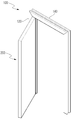
도 1은 실시예에 따른 스윙 도어를 나타낸 사시도,
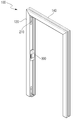
도 2는 실시예에 따른 스윙 도어를 나타낸 분리한 사시도,
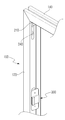
도 3은 상기 도 2에서 요부 확대 사시도,
도 4는 실시예에 따른 스윙 도어의 '힌지부재'를 확대한 사시도,
도 5는 실시예에 따른 스윙 도어의 닫힘 상태를 나타낸 단면도,
도 6은 실시예에 따른 스윙 도어의 열림 상태를 나타낸 단면도.1 is a perspective view showing a swing door according to an embodiment,
2 is a perspective view illustrating a swing door according to an embodiment,
Fig. 3 is an enlarged perspective view of Fig. 2,
4 is an enlarged perspective view of a 'hinge member' of a swing door according to an embodiment,
5 is a cross-sectional view illustrating a swing door according to an embodiment of the present invention,
6 is a cross-sectional view showing an open state of a swing door according to an embodiment.
이하 바람직한 실시예를 첨부된 도면을 토대로 상세하게 설명하면 다음과 같다.Hereinafter, preferred embodiments of the present invention will be described in detail with reference to the accompanying drawings.
하기에서 설명될 실시예는 본 고안이 속하는 기술분야에서 통상의 지식을 가진 자가 고안을 용이하게 실시할 수 있을 정도로 상세하게 설명하기 위한 것이며, 이로 인해 본 고안의 기술적인 사상 및 범주가 한정되는 것을 의미하지는 않는다.The embodiments described below are intended to be illustrative in nature to enable those skilled in the art to easily carry out the invention and that the technical idea and scope of the present invention will be limited It does not mean anything.
또한, 도면에 도시된 구성요소의 크기나 형상 등은 설명의 명료성과 편의상 과장되게 도시될 수 있으며, 본 고안의 구성 및 작용을 고려하여 특별히 정의된 용어들은 사용자, 운용자의 의도 또는 관례에 따라 달라질 수 있고, 이러한 용어들에 대한 정의는 본 명세서 전반에 걸친 내용을 토대로 내려져야 함을 밝혀둔다. In addition, the size and shape of the components shown in the drawings may be exaggerated for clarity and convenience of explanation, and the terms defined in particular in consideration of the configuration and operation of the present invention may vary depending on the intention or custom of the user or the operator It should be noted that the definitions of these terms should be made on the basis of the contents throughout this specification.
첨부된 도면 중에서, 도 1은 실시예에 따른 스윙 도어를 나타낸 사시도, 도 2는 실시예에 따른 스윙 도어를 나타낸 분리한 사시도, 도 3은 상기 도 2에서 요부 확대 사시도, 도 4는 실시예에 따른 스윙 도어의 '힌지부재'를 확대한 사시도, 도 5는 실시예에 따른 스윙 도어의 닫힘 상태를 나타낸 단면도, 도 6은 실시예에 따른 스윙 도어의 열림 상태를 나타낸 단면도이다.2 is a perspective view showing a swing door according to an embodiment of the present invention, FIG. 3 is an enlarged perspective view of the swing door in FIG. 2, and FIG. 4 is a perspective view of a swing door according to an embodiment of the present invention. FIG. 5 is a cross-sectional view illustrating a swing door according to an embodiment of the present invention, and FIG. 6 is a cross-sectional view illustrating a swing door according to an embodiment of the present invention.
도 1 내지 도 6에 도시된 바와 같이, 본 고안에 따른 스윙 도어는, 양측에 수직하게 형성되는 측면바(120)와, 양측 측면바(120)의 상단을 연결하는 상단바(140)로 구성되는 문틀(100)과, 상기 문틀(100)의 일측 내면의 상부에 형성되는 제1피봇힌지(210)와, 일측 내면의 하부에 형성되는 제2피봇힌지(220)가 연결되어 회전되는 도어(200)를 포함한다. 1 to 6, the swing door according to the present invention includes a
제1,2피봇힌지(210)(220) 각각은 문틀(100)의 내측 모서리에 부착되며 수직부와 수평부로 된 'ㄱ'자 형의 프레임(240)과, 상기 수평부에 돌출 형성되어 도어(200)에 끼움결합되는 피봇축(230)으로 구성된다. Each of the first and second pivot hinges 210 and 220 is attached to the inner edge of the
따라서 제1피봇힌지(210)가 도어(200)의 상부에 결합되고, 제2피봇힌지(220)는 도어(200)의 하부에 결합되어 도어(200)의 회전 작동을 가능하게 한다. The
또한 문틀(100)의 일측 내면의 중간부위에 부착되는 제1고정편(310)과, 상기 제1고정편(310)과 축핀(340)으로 결합되며 상기 도어(200)의 측면에 부착되는 제2고정편(320)으로 구성된 힌지부재(300);를 포함한다.A
상기 힌지부재(300)는 상기 제1고정편(310)에 오목하게 홈(312)이 형성되고, 상기 축핀(340)이 상기 홈(312)의 일측에 결합되며, 상기 축핀(340)의 외면에 일단이 연결되고 타단은 제2고정편(320)에 연결되며 접혔을때 상기 홈(312)에 삽입되는 플랩(330)을 포함하여 구성된다. The
상기 제1고정편(310)은 도어(200)의 측면에 설치되는 것으로, 직사각형의 평판이되 중간부위에 일정 깊이를 갖는 홈(312)이 오목하게 형성되고 복수의 나사체결공(350)이 형성되어 나사체결공(350)에 나사가 결합되어 도어(200)의 측면에 장착된다. The
상기 홈(312)에 플랩(330)의 일단이 축핀(340)으로 결합되어 회전 가능하도록 형성되며, 플랩(330)의 타단은 제2고정편(320)에 고정된다. One end of the
상기 제2고정편(320)은 도어(200)의 측면에 형성된 장착홈(205)에 억지끼움으로 결합되는 끼움부(322)와, 상기 끼움부(322)의 일측에 형성되어 장착홈(205)을 가리는 플레이트(324) 및 끼움부(322)의 측면에 다수 형성되는 걸림턱(326)으로 구성된다. The
이와 같이 구성된 실시예의 작용을 설명하면 다음과 같다.The operation of the thus configured embodiment will be described as follows.
문틀(100)에 도어(200)를 결합시키되 제1피봇힌지(210)와 제2피봇힌지(220)가 각기 도어(200)의 상하부에 결합되도록 하여 도어(200)가 회전될 수 있게 결합시킨다.The
이후 힌지부재(300)를 도어(200)의 중간부위에 적어도 한개 이상 장착시킨다.Thereafter, at least one
먼저 제1고정편(310)을 도어(200)의 측면에 형성된 장착부()에 억지끼움으로 결합시키고, 제2고정편(320)은 문틀(100)의 측면에 결합시킨 후 나사를 체결하여 고정시킨다. The
이후 도어(200)를 개폐작동시키면 힌지부재(300)의 절첩 작동에 의해 개폐 작동이 안정적으로 유지될 수 있고, 도어(200)에 강풍과 같은 외력이 가해져서 흔들림이 작용하더라도 도어(200)의 중간 부위에 결합된 힌지부재(300)가 지지력을 발휘하게 되므로 흔들림을 방지할 수 있게 된다. Closing operation of the
비록 바람직한 실시예와 관련하여 설명되어졌지만, 고안의 요지와 범위로부터 벗어남이 없이 다양한 수정 및 변형이 가능한 것은 당업자라면 용이하게 인식할 수 있을 것이며, 이러한 변경 및 수정은 모두 첨부된 청구의 범위에 속함은 자명하다.It will be apparent to those skilled in the art that various modifications and variations can be made in the present invention without departing from the spirit and scope of the invention, and all such changes and modifications are intended to be included within the scope of the appended claims. It is self-evident.
100 : 문틀 120 : 측면바
140 : 상단바 210 : 제1피봇힌지
220 : 제2피봇힌지 200 : 도어
240 ; 프레임 230 ; 피봇축
300 : 힌지부재 310 : 제1고정편
320 : 제2고정편 340 : 축핀100: door frame 120: side bar
140: top bar 210: first pivot hinge
220: second pivot hinge 200: door
240; Frame 230; Pivot axis
300: hinge member 310: first fixing piece
320: second fixing piece 340:
Claims (3)
상기 문틀의 일측 내면의 중간부위에 부착되는 제1고정편과, 상기 제1고정편과 축핀으로 결합되며 상기 도어의 측면에 부착되는 제2고정편으로 구성된 힌지부재;
를 포함하여 이루어진 것을 특징으로 하는 스윙 도어.A first pivot hinge formed at an upper portion of one inner side surface of the door frame, and a second pivot hinge formed at a lower portion of one inner side surface, And a door to which a hinge is connected and rotated,
A hinge member composed of a first fixing piece attached to an intermediate portion of one inner side surface of the door frame and a second fixing piece connected to the side surface of the door by the first fixing piece and the shaft pin;
Wherein the swinging door comprises:
상기 힌지부재는
상기 제1고정편에 오목하게 홈이 형성되고,
상기 축핀이 상기 홈의 일측에 결합되며,
상기 축핀의 외면에 일단이 연결되고 타단은 제2고정편에 연결되며 접혔을때 상기 홈에 삽입되는 플랩을 포함하는 것을 특징으로 하는 스윙 도어.The method according to claim 1,
The hinge member
Wherein a groove is formed concavely in the first fixing piece,
The shaft pin is coupled to one side of the groove,
And a flap having one end connected to the outer surface of the shaft pin and the other end connected to the second fixing piece and inserted into the groove when folded.
상기 제2고정편은 도어의 측면에 형성된 장착홈에 억지끼움으로 결합되는 끼움부와, 상기 끼움부의 일측에 형성되어 장착홈을 가리는 플레이트 및 끼움부의 측면에 다수 형성되는 걸림턱을 포함하는 것을 특징으로 하는 스윙 도어.The method according to claim 1,
And a plurality of locking protrusions formed on a side surface of the fitting portion and formed on one side of the fitting portion to cover the mounting groove, characterized in that the second fixing piece includes a plurality of locking protrusions formed on one side of the fitting portion, A swinging door.
Priority Applications (1)
| Application Number | Priority Date | Filing Date | Title |
|---|---|---|---|
| KR2020170004517U KR20190000574U (en) | 2017-08-25 | 2017-08-25 | Swing door |
Applications Claiming Priority (1)
| Application Number | Priority Date | Filing Date | Title |
|---|---|---|---|
| KR2020170004517U KR20190000574U (en) | 2017-08-25 | 2017-08-25 | Swing door |
Related Child Applications (1)
| Application Number | Title | Priority Date | Filing Date |
|---|---|---|---|
| KR2020190004199U Division KR20190002676U (en) | 2019-10-17 | 2019-10-17 | Swing door |
Publications (1)
| Publication Number | Publication Date |
|---|---|
| KR20190000574U true KR20190000574U (en) | 2019-03-06 |
Family
ID=65728886
Family Applications (1)
| Application Number | Title | Priority Date | Filing Date |
|---|---|---|---|
| KR2020170004517U KR20190000574U (en) | 2017-08-25 | 2017-08-25 | Swing door |
Country Status (1)
| Country | Link |
|---|---|
| KR (1) | KR20190000574U (en) |
-
2017
- 2017-08-25 KR KR2020170004517U patent/KR20190000574U/en not_active IP Right Cessation
Similar Documents
| Publication | Publication Date | Title |
|---|---|---|
| CA3014174C (en) | Concealed external hinge with 180 degree rotation | |
| WO2007044838A3 (en) | Hinged window screen | |
| US20120043770A1 (en) | Safety door stopper | |
| KR20190002676U (en) | Swing door | |
| KR20190000574U (en) | Swing door | |
| US6862778B2 (en) | Self-supporting device to hinge toward opposite sides | |
| KR20180093706A (en) | Connection structure for preventing a finger of folding mothproof door | |
| KR200401544Y1 (en) | Ling for lock | |
| CN210563961U (en) | Hinge assembly | |
| KR200285596Y1 (en) | A Store Box Door Hinge Structure Of Kimchi Refrigerator | |
| KR101817247B1 (en) | Bracket for a digital door-lock | |
| KR200287926Y1 (en) | Woody door-supporting hinge | |
| KR102247630B1 (en) | Pivot hinge for door | |
| KR200391505Y1 (en) | A hinge | |
| KR101486191B1 (en) | Slide hinge | |
| KR200193251Y1 (en) | A hinge structure for doors | |
| KR100914953B1 (en) | Structure for catching of door in cabinet | |
| KR102318267B1 (en) | A Combined pivot and flag type hinge for fire prevention door | |
| EP1533439B1 (en) | Servo-lifting device | |
| KR101557582B1 (en) | Storagebox | |
| KR200376907Y1 (en) | Hinge | |
| KR200322916Y1 (en) | The pivot hinge for the opening and shutting door preventing fingers from being caught in the door | |
| KR20240001882A (en) | Hinge structure for door | |
| KR200406889Y1 (en) | Exterior concealed door hinge | |
| KR20090003053U (en) | Warehouse Door Hinge |
Legal Events
| Date | Code | Title | Description |
|---|---|---|---|
| A201 | Request for examination | ||
| E902 | Notification of reason for refusal | ||
| AMND | Amendment | ||
| E601 | Decision to refuse application | ||
| AMND | Amendment | ||
| X601 | Decision of rejection after re-examination |