KR20180137385A - Method and apparatus for rapidly reporting frequency measurement results in next generation mobile communication system - Google Patents
Method and apparatus for rapidly reporting frequency measurement results in next generation mobile communication system Download PDFInfo
- Publication number
- KR20180137385A KR20180137385A KR1020170106288A KR20170106288A KR20180137385A KR 20180137385 A KR20180137385 A KR 20180137385A KR 1020170106288 A KR1020170106288 A KR 1020170106288A KR 20170106288 A KR20170106288 A KR 20170106288A KR 20180137385 A KR20180137385 A KR 20180137385A
- Authority
- KR
- South Korea
- Prior art keywords
- pdcp
- message
- base station
- data
- terminal
- Prior art date
Links
Images


Classifications
-
- H—ELECTRICITY
- H04—ELECTRIC COMMUNICATION TECHNIQUE
- H04W—WIRELESS COMMUNICATION NETWORKS
- H04W24/00—Supervisory, monitoring or testing arrangements
- H04W24/10—Scheduling measurement reports ; Arrangements for measurement reports
-
- H—ELECTRICITY
- H04—ELECTRIC COMMUNICATION TECHNIQUE
- H04L—TRANSMISSION OF DIGITAL INFORMATION, e.g. TELEGRAPHIC COMMUNICATION
- H04L69/00—Network arrangements, protocols or services independent of the application payload and not provided for in the other groups of this subclass
- H04L69/04—Protocols for data compression, e.g. ROHC
-
- H—ELECTRICITY
- H04—ELECTRIC COMMUNICATION TECHNIQUE
- H04L—TRANSMISSION OF DIGITAL INFORMATION, e.g. TELEGRAPHIC COMMUNICATION
- H04L69/00—Network arrangements, protocols or services independent of the application payload and not provided for in the other groups of this subclass
- H04L69/22—Parsing or analysis of headers
-
- H—ELECTRICITY
- H04—ELECTRIC COMMUNICATION TECHNIQUE
- H04W—WIRELESS COMMUNICATION NETWORKS
- H04W72/00—Local resource management
-
- H—ELECTRICITY
- H04—ELECTRIC COMMUNICATION TECHNIQUE
- H04W—WIRELESS COMMUNICATION NETWORKS
- H04W48/00—Access restriction; Network selection; Access point selection
- H04W48/08—Access restriction or access information delivery, e.g. discovery data delivery
- H04W48/12—Access restriction or access information delivery, e.g. discovery data delivery using downlink control channel
Abstract
Description
본 발명은 차세대 이동 통신 시스템에서 단말이 빠르게 주파수 측정 결과를 보고할 수 있도록 하는 방법 및 장치에 관한 것이다. BACKGROUND OF THE
4G 통신 시스템 상용화 이후 증가 추세에 있는 무선 데이터 트래픽 수요를 충족시키기 위해, 개선된 5G 통신 시스템 또는 pre-5G 통신 시스템을 개발하기 위한 노력이 이루어지고 있다. 이러한 이유로, 5G 통신 시스템 또는 pre-5G 통신 시스템은 4G 네트워크 이후 (Beyond 4G Network) 통신 시스템 또는 LTE 시스템 이후 (Post LTE) 이후의 시스템이라 불리어지고 있다. 높은 데이터 전송률을 달성하기 위해, 5G 통신 시스템은 초고주파(mmWave) 대역 (예를 들어, 60기가(60GHz) 대역과 같은)에서의 구현이 고려되고 있다. 초고주파 대역에서의 전파의 경로손실 완화 및 전파의 전달 거리를 증가시키기 위해, 5G 통신 시스템에서는 빔포밍(beamforming), 거대 배열 다중 입출력(massive MIMO), 전차원 다중입출력(Full Dimensional MIMO: FD-MIMO), 어레이 안테나(array antenna), 아날로그 빔형성(analog beam-forming), 및 대규모 안테나 (large scale antenna) 기술들이 논의되고 있다. 또한 시스템의 네트워크 개선을 위해, 5G 통신 시스템에서는 진화된 소형 셀, 개선된 소형 셀 (advanced small cell), 클라우드 무선 액세스 네트워크 (cloud radio access network: cloud RAN), 초고밀도 네트워크 (ultra-dense network), 기기 간 통신 (Device to Device communication: D2D), 무선 백홀 (wireless backhaul), 이동 네트워크 (moving network), 협력 통신 (cooperative communication), CoMP (Coordinated Multi-Points), 및 수신 간섭제거 (interference cancellation) 등의 기술 개발이 이루어지고 있다. 이 밖에도, 5G 시스템에서는 진보된 코딩 변조(Advanced Coding Modulation: ACM) 방식인 FQAM (Hybrid FSK and QAM Modulation) 및 SWSC (Sliding Window Superposition Coding)과, 진보된 접속 기술인 FBMC(Filter Bank Multi Carrier), NOMA(non orthogonal multiple access), 및SCMA(sparse code multiple access) 등이 개발되고 있다.Efforts are underway to develop an improved 5G or pre-5G communication system to meet the growing demand for wireless data traffic after commercialization of the 4G communication system. For this reason, a 5G communication system or a pre-5G communication system is called a system after a 4G network (Beyond 4G network) communication system or after a LTE system (Post LTE). To achieve a high data rate, 5G communication systems are being considered for implementation in very high frequency (mmWave) bands (e.g., 60 gigahertz (60GHz) bands). In order to mitigate the path loss of the radio wave in the very high frequency band and to increase the propagation distance of the radio wave, in the 5G communication system, beamforming, massive MIMO, full-dimension MIMO (FD-MIMO ), Array antennas, analog beam-forming, and large scale antenna technologies are being discussed. In order to improve the network of the system, the 5G communication system has developed an advanced small cell, an advanced small cell, a cloud radio access network (cloud RAN), an ultra-dense network, (D2D), a wireless backhaul, a moving network, cooperative communication, Coordinated Multi-Points (CoMP), and interference cancellation Have been developed. In addition, in the 5G system, the Advanced Coding Modulation (ACM) scheme, Hybrid FSK and QAM Modulation (FQAM) and Sliding Window Superposition Coding (SWSC), the advanced connection technology, Filter Bank Multi Carrier (FBMC) (non-orthogonal multiple access), and SCMA (sparse code multiple access).
한편, 인터넷은 인간이 정보를 생성하고 소비하는 인간 중심의 연결 망에서, 사물 등 분산된 구성 요소들 간에 정보를 주고 받아 처리하는 IoT(Internet of Things, 사물인터넷) 망으로 진화하고 있다. 클라우드 서버 등과의 연결을 통한 빅데이터(Big data) 처리 기술 등이 IoT 기술에 결합된 IoE (Internet of Everything) 기술도 대두되고 있다. IoT를 구현하기 위해서, 센싱 기술, 유무선 통신 및 네트워크 인프라, 서비스 인터페이스 기술, 및 보안 기술과 같은 기술 요소 들이 요구되어, 최근에는 사물간의 연결을 위한 센서 네트워크(sensor network), 사물 통신(Machine to Machine, M2M), MTC(Machine Type Communication)등의 기술이 연구되고 있다. IoT 환경에서는 연결된 사물들에서 생성된 데이터를 수집, 분석하여 인간의 삶에 새로운 가치를 창출하는 지능형 IT(Internet Technology) 서비스가 제공될 수 있다. IoT는 기존의 IT(information technology)기술과 다양한 산업 간의 융합 및 복합을 통하여 스마트홈, 스마트 빌딩, 스마트 시티, 스마트 카 혹은 커넥티드 카, 스마트 그리드, 헬스 케어, 스마트 가전, 첨단의료서비스 등의 분야에 응용될 수 있다.On the other hand, the Internet is evolving into an Internet of Things (IoT) network in which information is exchanged between distributed components such as objects in a human-centered connection network where humans generate and consume information. IoE (Internet of Everything) technology, which combines IoT technology with big data processing technology through connection with cloud servers, is also emerging. In order to implement IoT, technology elements such as sensing technology, wired / wireless communication, network infrastructure, service interface technology and security technology are required. In recent years, sensor network, machine to machine , M2M), and MTC (Machine Type Communication). In the IoT environment, an intelligent IT (Internet Technology) service can be provided that collects and analyzes data generated from connected objects to create new value in human life. IoT is a field of smart home, smart building, smart city, smart car or connected car, smart grid, health care, smart home appliance, and advanced medical service through fusion of existing information technology . ≪ / RTI >
이에, 5G 통신 시스템을 IoT 망에 적용하기 위한 다양한 시도들이 이루어지고 있다. 예를 들어, 센서 네트워크(sensor network), 사물 통신(Machine to Machine, M2M), MTC(Machine Type Communication)등의 기술이 5G 통신 기술이 빔 포밍, MIMO, 및 어레이 안테나 등의 기법에 의해 구현되고 있는 것이다. 앞서 설명한 빅데이터 처리 기술로써 클라우드 무선 액세스 네트워크(cloud RAN)가 적용되는 것도 5G 기술과 IoT 기술 융합의 일 예라고 할 수 있을 것이다.Accordingly, various attempts have been made to apply the 5G communication system to the IoT network. For example, technologies such as a sensor network, a machine to machine (M2M), and a machine type communication (MTC) are implemented by techniques such as beamforming, MIMO, and array antennas It is. The application of the cloud RAN as the big data processing technology described above is an example of the convergence of 5G technology and IoT technology.
최근 LTE(Long Term Evolution) 및 LTE-Advanced의 발전에 따라 차세대 이동 통신 시스템에서 단말이 빠르게 주파수 측정 결과를 보고할 수 있도록 하는 방법 및 장치가 필요하다. There is a need for a method and an apparatus for enabling a terminal to quickly report a frequency measurement result in a next generation mobile communication system according to recent developments of LTE (Long Term Evolution) and LTE-Advanced.
본 발명의 목적은 차세대 이동 통신 시스템에서 높은 데이터 전송률과 낮은 전송 지연을 갖는 서비스를 지원하기 위해서 기지국은 단말에게 빠르게 주파수 응집 기술(CA, Carrier aggregation)이나 이중 접속(DC, Dual connectivity) 기술을 설정해줄 필요가 있다. 하지만 상기와 같은 기술들을 단말에게 설정해주기 위해서는 단말의 주파수 측정 결과가 필요하다. 따라서 단말의 주파수 측정 결과를 빨리 보고 받을 수 있는 방법을 제안한다. SUMMARY OF THE INVENTION An object of the present invention is to provide a mobile communication system in which a base station quickly sets up a carrier aggregation (CA) or a dual connectivity (DC) technology to support a service having a high data rate and a low transmission delay in a next generation mobile communication system I need to do it. However, in order to set the above techniques to the UE, the frequency measurement result of the UE is needed. Therefore, we propose a method to receive the frequency measurement result of the terminal quickly.
또한 본 발명의 또다른 목적은 차세대 이동 통신 시스템에서는 RLC 계층에서 수신 패킷들에 대한 순차적인 전달 기능을 지원하지 않기 때문에 PDCP 계층에서 상위 계층으로 순차적인 전달 기능을 지원해야 할 필요가 있으며, PDCP 계층에서 재전송을 요청할 수 있는 경우, 이 또한 고려되어야 한다. 만약 상위 계층에서 순차적인 전달 기능을 지원하는 경우, PDCP 계층에서도 순차적인 전달 기능을 지원할 필요가 없을 수 있다. 따라서 이러한 다양한 경우를 고려하여 PDCP 계층의 동작 모드들이 지원될 필요가 있다. It is a further object of the present invention to provide a method and apparatus for supporting sequential forwarding of packets received from a PDCP layer to an upper layer in a next generation mobile communication system because the RLC layer does not support sequential forwarding of received packets, If retransmission can be requested, this should also be considered. If the higher layers support sequential forwarding functions, it may not be necessary to support sequential forwarding functions in the PDCP layer as well. Therefore, it is necessary to support the operation modes of the PDCP layer in consideration of various cases.
또한 본 발명의 또다른 목적은 무선통신시스템에서 단말이 서로 다른 혹은 동일한 무선접속기술 (Radio Access Technology, RAT)를 사용하는 기지국들을 동시에 연결하여 사용할 때, 각 기지국의 연결 상태를 판단하는 방법 및 이에 대해 처리하는 방법에 관한 것이다.It is still another object of the present invention to provide a method of determining a connection state of each base station when a terminal uses different or same radio access technology (RAT) And a method for processing the same.
상기와 같은 문제점을 해결하기 위한 본 발명은 무선 통신 시스템에서 제어 신호 처리 방법에 있어서, 기지국으로부터 전송되는 제1 제어 신호를 수신하는 단계; 상기 수신된 제1 제어 신호를 처리하는 단계; 및 상기 처리에 기반하여 생성된 제2 제어 신호를 상기 기지국으로 전송하는 단계를 포함하는 것을 특징으로 한다.According to an aspect of the present invention, there is provided a method of processing a control signal in a wireless communication system, the method comprising: receiving a first control signal transmitted from a base station; Processing the received first control signal; And transmitting the second control signal generated based on the process to the base station.
본 발명의 일 실시예에 따르면, 본 발명에서는 차세대 이동 통신 시스템에서 단말이 주변 주파수 측정 결과를 기지국에게 빨리 보고할 수 있도록 하는 방법을 제안함으로써, 기지국이 단말에게 주파수 응집 기술 혹은 이중 접속 기술을 빠르게 설정할 수 있도록 한다. According to an embodiment of the present invention, the present invention proposes a method for allowing a terminal to quickly report a measurement result of a peripheral frequency to a base station in a next generation mobile communication system, So that it can be set.
또한, 본 발명의 또다른 실시예에 따르면, 본 발명에서는 차세대 이동 통신 시스템에서 요구되는 다양한 기능을 지원하기 위해서 PDCP 계층의 다양한 모드들을 제안하고, 상기 모드들의 동작 절차 및 각 모드를 설정하는 방법들을 제안하여 차세대 이동 통신 시스템에서 다양한 기능을 지원할 수 있도록 한다. In addition, according to another embodiment of the present invention, various modes of the PDCP layer are proposed to support various functions required in the next generation mobile communication system, and an operation procedure of the modes and methods of setting each mode So that various functions can be supported in the next generation mobile communication system.
또한, 본 발명의 또다른 실시예에 따르면, 본 발명을 통해, 단말은 각 기지국과의 통신 오류 발생 시, 이를 판단하여 연결을 복구할 수 있다.In addition, according to another embodiment of the present invention, when a communication error occurs with each base station, the terminal can recover the connection by determining the error.
도 1a는 본 발명이 적용될 수 있는 LTE 시스템의 구조를 도시하는 도면이다.
도 1b는 본 발명이 적용될 수 있는 LTE 시스템에서 무선 프로토콜 구조를 나타낸 도면이다.
도 1c는 본 발명이 적용될 수 있는 차세대 이동통신 시스템의 구조를 도시하는 도면이다.
도 1d는 본 발명이 적용될 수 있는 차세대 이동통신 시스템의 무선 프로토콜 구조를 나타낸 도면이다. .
도 1e는 본 발명의 차세대 이동 통신 시스템에서 단말이 일찍 주파수 측정(early measurement)을 수행할 수 있도록 하고, 빠르게 주파수 측정 결과를 보고(fast measurement report)할 수 있도록 하는 제 1-1 실시 예를 나타낸 도면이다.
도 1f는 본 발명의 차세대 이동 통신 시스템에서 단말이 일찍 주파수 측정(early measurement)을 수행할 수 있도록 하고, 빠르게 주파수 측정 결과를 보고(fast measurement report)할 수 있도록 하는 제 1-2 실시 예를 나타낸 도면이다.
도 1g는 본 발명의 차세대 이동 통신 시스템에서 단말이 일찍 주파수 측정(early measurement)을 수행할 수 있도록 하고, 빠르게 주파수 측정 결과를 보고(fast measurement report)할 수 있도록 하는 제 1-3 실시 예를 나타낸 도면이다.
도 1h는 본 발명의 차세대 이동 통신 시스템에서 단말이 일찍 주파수 측정(early measurement)을 수행하고 빠르게 주파수 측정 결과를 보고(fast measurement report)하는 단말 동작을 나타낸 도면이다.
도 1i에 본 발명의 실시 예가 적용될 수 있는 단말의 구조를 도시하였다.
도 1j는 본 발명의 실시 예가 적용될 수 있는 무선 통신 시스템에서 TRP의 블록 구성을 도시한다.
도 2a는 본 발명이 적용될 수 있는 LTE 시스템의 구조를 도시하는 도면이다.
도 2b는 본 발명이 적용될 수 있는 LTE 시스템에서 무선 프로토콜 구조를 나타낸 도면이다.
도 2c는 본 발명이 적용될 수 있는 차세대 이동통신 시스템의 구조를 도시하는 도면이다.
도 2d는 본 발명이 적용될 수 있는 차세대 이동통신 시스템의 무선 프로토콜 구조를 나타낸 도면이다.
도 2e는 본 발명에서 단말이 RRC 유휴 모드(RRC idle mode)에서 RRC 연결 모드(RRC connected mode)로 전환하여 네트워크와 연결을 설정하는 절차를 설명한 도면이다.
도 2f는 PDCP 계층에서 구동할 수 있는 PUSH 기반 윈도우 동작을 나타낸 도면이다.
도 2g는 PDCP 계층에서 구동할 수 있는 PULL 기반 윈도우 동작을 나타낸 도면이다.
도 2h는 본 발명에서 단말이 PDCP 계층 장치 설정 정보를 수신하고 PDCP 모드를 결정하고 그에 따라 동작하는 단말 동작을 나타낸 도면이다.
도 2i에 본 발명의 실시 예가 적용될 수 있는 단말의 구조를 도시하였다.
도 2j는 본 발명의 실시 예가 적용될 수 있는 무선 통신 시스템에서 TRP의 블록 구성을 도시한다.
도 2k는 본 발명에서 제안하는 차세대 이동 통신 시스템의 PDCP 계층에서 수신 윈도우 동작을 나타낸다.
도 3a은 본 발명의 설명을 위해 참고로 하는 LTE 시스템의 구조를 도시하는 도면이다.
도 3b는 본 발명의 설명을 위해 참고로 하는 LTE 시스템의 무선 프로토콜 구조를 나타낸 도면이다.
도 3c는 LTE 및 NR에서 다중 연결의 개념을 설명하기 위한 도면이다.
도 3d는 본 발명을 적용한 경우 단말과 기지국 간의 메시지 흐름 예시 도면이다.
도 3e는 본 발명을 적용한 경우 단말의 동작 순서 예시 도면이다.
도 3f는 본 발명의 실시 예에 따른 단말의 블록 구성 예시 도면이다. 1A is a diagram showing a structure of an LTE system to which the present invention can be applied.
1B is a diagram illustrating a wireless protocol structure in an LTE system to which the present invention can be applied.
1C is a diagram illustrating a structure of a next generation mobile communication system to which the present invention can be applied.
1D is a diagram illustrating a wireless protocol structure of a next generation mobile communication system to which the present invention can be applied. .
FIG. 1E is a block diagram illustrating a first embodiment in which a UE can perform an early measurement in a next generation mobile communication system and can quickly report a frequency measurement result (fast measurement report). FIG.
FIG. 1F shows a first embodiment in which the UE can perform early measurement in a next generation mobile communication system and can quickly report a frequency measurement (fast measurement report). FIG.
FIG. 1G shows a first to third embodiments in which a UE can perform early measurement in a next generation mobile communication system and can quickly report a frequency measurement (fast measurement report). FIG.
FIG. 1H is a diagram illustrating a terminal operation in which the UE performs an early measurement and a fast measurement report in a next generation mobile communication system according to the present invention.
FIG. 1I illustrates a structure of a terminal to which an embodiment of the present invention can be applied.
1J illustrates a block diagram of a TRP in a wireless communication system to which an embodiment of the present invention may be applied.
2A is a diagram showing a structure of an LTE system to which the present invention can be applied.
2B is a diagram illustrating a wireless protocol structure in an LTE system to which the present invention can be applied.
2C is a diagram illustrating a structure of a next generation mobile communication system to which the present invention can be applied.
FIG. 2D is a diagram illustrating a wireless protocol structure of a next generation mobile communication system to which the present invention can be applied.
FIG. 2E is a diagram for explaining a procedure for establishing a connection with a network by switching a terminal from the RRC idle mode to the RRC connected mode (RRC connected mode) in the present invention.
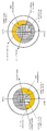
FIG. 2F is a diagram illustrating a PUSH-based window operation that can be performed in the PDCP layer.
FIG. 2G is a diagram illustrating a PULL-based window operation that can be performed in the PDCP layer.
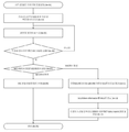
2H is a diagram illustrating a UE operation in which a UE receives PDCP layer setup information and determines a PDCP mode and operates according to the PDCP layer setup information.
FIG. 2I illustrates a structure of a terminal to which an embodiment of the present invention can be applied.
2J illustrates a block diagram of a TRP in a wireless communication system to which an embodiment of the present invention may be applied.
2K illustrates a reception window operation in the PDCP layer of the next generation mobile communication system proposed in the present invention.
FIG. 3A is a diagram showing a structure of a LTE system as a reference for explaining the present invention.
FIG. 3B is a diagram illustrating a wireless protocol structure of an LTE system for the purpose of explanation of the present invention.
3C is a diagram for explaining the concept of multiple connections in LTE and NR.
FIG. 3D is a diagram illustrating a message flow between a terminal and a base station when the present invention is applied.
3E is a diagram illustrating an example of the operation sequence of the terminal when the present invention is applied.
FIG. 3F is a diagram illustrating an example of the configuration of a terminal according to an embodiment of the present invention.
이하, 본 발명의 실시예를 첨부한 도면과 함께 상세히 설명한다. 또한 본 발명을 설명함에 있어서 관련된 공지 기능 혹은 구성에 대한 구체적인 설명이 본 발명의 요지를 불필요하게 흐릴 수 있다고 판단된 경우 그 상세한 설명은 생략한다. 그리고 후술되는 용어들은 본 발명에서의 기능을 고려하여 정의된 용어들로서 이는 사용자, 운용자의 의도 또는 관례 등에 따라 달라질 수 있다. 그러므로 그 정의는 본 명세서 전반에 걸친 내용을 토대로 내려져야 할 것이다.Hereinafter, embodiments of the present invention will be described in detail with reference to the accompanying drawings. In the following description, a detailed description of known functions and configurations incorporated herein will be omitted when it may make the subject matter of the present invention rather unclear. The following terms are defined in consideration of the functions of the present invention, and these may be changed according to the intention of the user, the operator, or the like. Therefore, the definition should be based on the contents throughout this specification.
본 발명의 이점 및 특징, 그리고 그것들을 달성하는 방법은 첨부되는 도면과 함께 상세하게 후술되어 있는 실시 예들을 참조하면 명확해질 것이다. 그러나 본 발명은 이하에서 개시되는 실시 예들에 한정되는 것이 아니라 서로 다른 다양한 형태로 구현될 수 있으며, 단지 본 실시 예들은 본 발명의 개시가 완전하도록 하고, 본 발명이 속하는 기술분야에서 통상의 지식을 가진 자에게 발명의 범주를 완전하게 알려주기 위해 제공되는 것이며, 본 발명은 청구항의 범주에 의해 정의될 뿐이다. 명세서 전체에 걸쳐 동일 참조 부호는 동일 구성 요소를 지칭한다.BRIEF DESCRIPTION OF THE DRAWINGS The advantages and features of the present invention and the manner of achieving them will become apparent with reference to the embodiments described in detail below with reference to the accompanying drawings. The present invention may, however, be embodied in many different forms and should not be construed as being limited to the embodiments set forth herein. Rather, these embodiments are provided so that this disclosure will be thorough and complete, and will fully convey the concept of the invention to those skilled in the art. Is provided to fully convey the scope of the invention to those skilled in the art, and the invention is only defined by the scope of the claims. Like reference numerals refer to like elements throughout the specification.
<제1실시예>≪
이하 첨부된 도면을 참조하여 본 발명의 동작 원리를 상세히 설명한다. 하기에서 본 발명을 설명하기에 있어 관련된 공지 기능 또는 구성에 대한 구체적인 설명이 본 발명의 요지를 불필요하게 흐릴 수 있다고 판단되는 경우에는 그 상세한 설명을 생략할 것이다. 그리고 후술되는 용어들은 본 발명에서의 기능을 고려하여 정의된 용어들로서 이는 사용자, 운용자의 의도 또는 관례 등에 따라 달라질 수 있다. 그러므로 그 정의는 본 명세서 전반에 걸친 내용을 토대로 내려져야 할 것이다.Hereinafter, the operation principle of the present invention will be described in detail with reference to the accompanying drawings. DETAILED DESCRIPTION OF THE PREFERRED EMBODIMENTS Hereinafter, a detailed description of known functions and configurations incorporated herein will be omitted when it may make the subject matter of the present invention rather unclear. The following terms are defined in consideration of the functions of the present invention, and these may be changed according to the intention of the user, the operator, or the like. Therefore, the definition should be based on the contents throughout this specification.
하기에서 본 발명을 설명함에 있어 관련된 공지 기능 또는 구성에 대한 구체적인 설명이 본 발명의 요지를 불필요하게 흐릴 수 있다고 판단되는 경우에는 그 상세한 설명을 생략할 것이다. 이하 첨부된 도면을 참조하여 본 발명의 실시 예를 설명하기로 한다.In the following description of the present invention, a detailed description of known functions and configurations incorporated herein will be omitted when it may make the subject matter of the present invention rather unclear. DESCRIPTION OF THE PREFERRED EMBODIMENTS Hereinafter, embodiments of the present invention will be described with reference to the accompanying drawings.
이하 설명에서 사용되는 접속 노드(node)를 식별하기 위한 용어, 망 객체(network entity)들을 지칭하는 용어, 메시지들을 지칭하는 용어, 망 객체들 간 인터페이스를 지칭하는 용어, 다양한 식별 정보들을 지칭하는 용어 등은 설명의 편의를 위해 예시된 것이다. 따라서, 본 발명이 후술되는 용어들에 한정되는 것은 아니며, 동등한 기술적 의미를 가지는 대상을 지칭하는 다른 용어가 사용될 수 있다.A term used for identifying a connection node used in the following description, a term referring to network entities, a term referring to messages, a term indicating an interface between network objects, a term indicating various identification information Etc. are illustrated for convenience of explanation. Therefore, the present invention is not limited to the following terms, and other terms referring to objects having equivalent technical meanings can be used.
이하 설명의 편의를 위하여, 본 발명은 3GPP LTE(3rd Generation Partnership Project Long Term Evolution) 규격에서 정의하고 있는 용어 및 명칭들을 사용한다. 하지만, 본 발명이 상기 용어 및 명칭들에 의해 한정되는 것은 아니며, 다른 규격에 따르는 시스템에도 동일하게 적용될 수 있다. 본 발명에서 eNB는 설명의 편의를 위하여 gNB와 혼용되어 사용될 수 있다. 즉 eNB로 설명한 기지국은 gNB를 나타낼 수 있다. For convenience of explanation, the present invention uses terms and names defined in 3GPP LTE (3rd Generation Partnership Project Long Term Evolution) standard. However, the present invention is not limited by the above-mentioned terms and names, and can be equally applied to systems conforming to other standards. In the present invention, eNB can be used in combination with gNB for convenience of explanation. That is, the base station described as an eNB may represent a gNB.
도 1a는 본 발명이 적용될 수 있는 LTE 시스템의 구조를 도시하는 도면이다. 1A is a diagram showing a structure of an LTE system to which the present invention can be applied.
도 1a을 참조하면, 도시한 바와 같이 LTE 시스템의 무선 액세스 네트워크는 차세대 기지국(Evolved Node B, 이하 ENB, Node B 또는 기지국)(1a-05, 1a-10, 1a-15, 1a-20)과 MME (1a-25, Mobility Management Entity) 및 S-GW(1a-30, Serving-Gateway)로 구성된다. 사용자 단말(User Equipment, 이하 UE 또는 단말)(1a-35)은 ENB(1a-05 ~ 1a-20) 및 S-GW(1a-30)를 통해 외부 네트워크에 접속한다.1A, a radio access network of an LTE system includes an Evolved Node B (hereinafter, referred to as an ENB, a Node B or a base station) 1a-05, 1a-10, 1a-15 and 1a-20, MME (Mobility Management Entity) 1a-25, and Serving-Gateway (S-GW) 1a-30. A user equipment (hereinafter referred to as UE or UE) 1a-35 accesses an external network through the
도 1a에서 ENB(1a-05 ~ 1a-20)는 UMTS 시스템의 기존 노드 B에 대응된다. ENB는 UE(1a-35)와 무선 채널로 연결되며 기존 노드 B 보다 복잡한 역할을 수행한다. LTE 시스템에서는 인터넷 프로토콜을 통한 VoIP(Voice over IP)와 같은 실시간 서비스를 비롯한 모든 사용자 트래픽이 공용 채널(shared channel)을 통해 서비스 되므로, UE들의 버퍼 상태, 가용 전송 전력 상태, 채널 상태 등의 상태 정보를 취합해서 스케줄링을 하는 장치가 필요하며, 이를 ENB(1a-05 ~ 1a-20)가 담당한다. 하나의 ENB는 통상 다수의 셀들을 제어한다. 예컨대, 100 Mbps의 전송 속도를 구현하기 위해서 LTE 시스템은 예컨대, 20 MHz 대역폭에서 직교 주파수 분할 다중 방식(Orthogonal Frequency Division Multiplexing, 이하 OFDM이라 한다)을 무선 접속 기술로 사용한다. 또한 단말의 채널 상태에 맞춰 변조 방식(modulation scheme)과 채널 코딩률(channel coding rate)을 결정하는 적응 변조 코딩(Adaptive Modulation & Coding, 이하 AMC라 한다) 방식을 적용한다. S-GW(1a-30)는 데이터 베어러를 제공하는 장치이며, MME(1a-25)의 제어에 따라서 데이터 베어러를 생성하거나 제거한다. MME는 단말에 대한 이동성 관리 기능은 물론 각종 제어 기능을 담당하는 장치로 다수의 기지국 들과 연결된다. In FIG. 1A, the
도 1b는 본 발명이 적용될 수 있는 LTE 시스템에서 무선 프로토콜 구조를 나타낸 도면이다. 1B is a diagram illustrating a wireless protocol structure in an LTE system to which the present invention can be applied.
도 1b를 참조하면, LTE 시스템의 무선 프로토콜은 단말과 ENB에서 각각 PDCP (Packet Data Convergence Protocol 1b-05, 1b-40), RLC (Radio Link Control 1b-10, 1b-35), MAC (Medium Access Control 1b-15, 1b-30)으로 이루어진다. PDCP (Packet Data Convergence Protocol)(1b-05, 1b-40)는 IP 헤더 압축/복원 등의 동작을 담당한다. PDCP의 주요 기능은 하기와 같이 요약된다.Referring to FIG. 1B, the wireless protocol of the LTE system includes PDCP (Packet
- 헤더 압축 및 압축 해제 기능(Header compression and decompression: ROHC only)- Header compression and decompression (ROHC only)
- 사용자 데이터 전송 기능 (Transfer of user data)- Transfer of user data
- 순차적 전달 기능(In-sequence delivery of upper layer PDUs at PDCP re-establishment procedure for RLC AM)- In-sequence delivery of upper layer PDUs at PDCP re-establishment procedure for RLC AM
- 순서 재정렬 기능(For split bearers in DC (only support for RLC AM): PDCP PDU routing for transmission and PDCP PDU reordering for reception)- For split bearers in DC (only support for RLC AM): PDCP PDU routing for transmission and PDCP PDU reordering for reception.
- 중복 탐지 기능(Duplicate detection of lower layer SDUs at PDCP re-establishment procedure for RLC AM)- Duplicate detection of lower layer SDUs at PDCP re-establishment procedure for RLC AM -
- 재전송 기능(Retransmission of PDCP SDUs at handover and, for split bearers in DC, of PDCP PDUs at PDCP data-recovery procedure, for RLC AM)- Retransmission function (PDCP SDUs at handover and for split bearers in DC, PDCP PDUs at PDCP data-recovery procedure, for RLC AM)
- 암호화 및 복호화 기능(Ciphering and deciphering)- Ciphering and deciphering function
- 타이머 기반 SDU 삭제 기능(Timer-based SDU discard in uplink.)- Timer-based SDU discard in uplink.
무선 링크 제어(Radio Link Control, 이하 RLC라고 한다)(1b-10, 1b-35)는 PDCP PDU(Packet Data Unit)를 적절한 크기로 재구성해서 ARQ 동작 등을 수행한다. RLC의 주요 기능은 하기와 같이 요약된다.Radio Link Control (RLC) 1b-10 and 1b-35 reconfigures a PDCP PDU (Packet Data Unit) to an appropriate size to perform an ARQ operation or the like. The main functions of the RLC are summarized as follows.
- 데이터 전송 기능(Transfer of upper layer PDUs)- Transfer of upper layer PDUs
- ARQ 기능(Error Correction through ARQ (only for AM data transfer))- ARQ function (Error Correction through ARQ (only for AM data transfer))
- 접합, 분할, 재조립 기능(Concatenation, segmentation and reassembly of RLC SDUs (only for UM and AM data transfer))- Concatenation, segmentation and reassembly of RLC SDUs (only for UM and AM data transfer)
- 재분할 기능(Re-segmentation of RLC data PDUs (only for AM data transfer))- Re-segmentation of RLC data PDUs (only for AM data transfer)
- 순서 재정렬 기능(Reordering of RLC data PDUs (only for UM and AM data transfer)- Reordering of RLC data PDUs (only for UM and AM data transfer)
- 중복 탐지 기능(Duplicate detection (only for UM and AM data transfer))- Duplicate detection (only for UM and AM data transfer)
- 오류 탐지 기능(Protocol error detection (only for AM data transfer))- Error detection (only for AM data transfer)
- RLC SDU 삭제 기능(RLC SDU discard (only for UM and AM data transfer))- RLC SDU discard function (RLC SDU discard (only for UM and AM data transfer))
- RLC 재수립 기능(RLC re-establishment)- RLC re-establishment function (RLC re-establishment)
MAC(1b-15, 1b-30)은 한 단말에 구성된 여러 RLC 계층 장치들과 연결되며, RLC PDU들을 MAC PDU에 다중화하고 MAC PDU로부터 RLC PDU들을 역다중화하는 동작을 수행한다. MAC의 주요 기능은 하기와 같이 요약된다.The
- 맵핑 기능(Mapping between logical channels and transport channels)- Mapping between logical channels and transport channels.
- 다중화 및 역다중화 기능(Multiplexing/demultiplexing of MAC SDUs belonging to one or different logical channels into/from transport blocks (TB) delivered to/from the physical layer on transport channels)- Multiplexing / demultiplexing of MAC SDUs belonging to one or different logical channels into / from transport blocks (TB) delivered to / from the physical layer on transport channels.
- 스케쥴링 정보 보고 기능(Scheduling information reporting)- Scheduling information reporting function
- HARQ 기능(Error correction through HARQ)- HARQ (Error correction through HARQ)
- 로지컬 채널 간 우선 순위 조절 기능(Priority handling between logical channels of one UE)- Priority handling between logical channels of one UE
- 단말간 우선 순위 조절 기능(Priority handling between UEs by means of dynamic scheduling)- Priority handling between UEs by means of dynamic scheduling
- MBMS 서비스 확인 기능(MBMS service identification)- MBMS service identification (MBMS service identification)
- 전송 포맷 선택 기능(Transport format selection)- Transport format selection function (Transport format selection)
- 패딩 기능(Padding)- Padding function
물리 계층(1b-20, 1b-25)은 상위 계층 데이터를 채널 코딩 및 변조하고, OFDM 심벌로 만들어서 무선 채널로 전송하거나, 무선 채널을 통해 수신한 OFDM 심벌을 복조하고 채널 디코딩해서 상위 계층으로 전달하는 동작을 한다.The
도 1c는 본 발명이 적용될 수 있는 차세대 이동통신 시스템의 구조를 도시하는 도면이다. 1C is a diagram illustrating a structure of a next generation mobile communication system to which the present invention can be applied.
도 1c을 참조하면, 도시한 바와 같이 차세대 이동통신 시스템(이하 NR 혹은 5G)의 무선 액세스 네트워크는 차세대 기지국(New Radio Node B, 이하 NR gNB 혹은 NR 기지국)(1c-10) 과 NR CN (1c-05, New Radio Core Network)로 구성된다. 사용자 단말(New Radio User Equipment, 이하 NR UE 또는 단말)(1c-15)은 NR gNB(1c-10) 및 NR CN (1c-05)를 통해 외부 네트워크에 접속한다.1C, a radio access network of a next generation mobile communication system (hereinafter referred to as NR or 5G) includes a next-generation base station (NR gNB or NR base station) 1c-10 and an
도 1c에서 NR gNB(1c-10)는 기존 LTE 시스템의 eNB (Evolved Node B)에 대응된다. NR gNB는 NR UE(1c-15)와 무선 채널로 연결되며 기존 노드 B 보다 더 월등한 서비스를 제공해줄 수 있다. 차세대 이동통신 시스템에서는 모든 사용자 트래픽이 공용 채널(shared channel)을 통해 서비스 되므로, UE들의 버퍼 상태, 가용 전송 전력 상태, 채널 상태 등의 상태 정보를 취합해서 스케줄링을 하는 장치가 필요하며, 이를 NR NB(1c-10)가 담당한다. 하나의 NR gNB는 통상 다수의 셀들을 제어한다. 현재 LTE 대비 초고속 데이터 전송을 구현하기 위해서 기존 최대 대역폭 이상을 가질 수 있고, 직교 주파수 분할 다중 방식(Orthogonal Frequency Division Multiplexing, 이하 OFDM이라 한다)을 무선 접속 기술로 하여 추가적으로 빔포밍 기술이 접목될 수 있다. 또한 단말의 채널 상태에 맞춰 변조 방식(modulation scheme)과 채널 코딩률(channel coding rate)을 결정하는 적응 변조 코딩(Adaptive Modulation & Coding, 이하 AMC라 한다) 방식을 적용한다. NR CN (1c-05)는 이동성 지원, 베어러 설정, QoS 설정 등의 기능을 수행한다. NR CN는 단말에 대한 이동성 관리 기능은 물론 각종 제어 기능을 담당하는 장치로 다수의 기지국 들과 연결된다. 또한 차세대 이동통신 시스템은 기존 LTE 시스템과도 연동될 수 있으며, NR CN이 MME (1c-25)와 네트워크 인터페이스를 통해 연결된다. MME는 기존 기지국인 eNB (1c-30)와 연결된다.1C, the NR gNB (1c-10) corresponds to the eNB (Evolved Node B) of the existing LTE system. The NR gNB is connected to the NR UE (1c-15) via a radio channel and can provide a superior service than the existing Node B. In the next generation mobile communication system, since all user traffic is served through a shared channel, a device for collecting and scheduling state information such as buffer status, available transmission power state, and channel state of UEs is required. (1c-10). One NR gNB typically controls multiple cells. In order to realize high-speed data transmission in comparison with the current LTE, it can have an existing maximum bandwidth or more, and additionally, beam-forming technology can be applied by using Orthogonal Frequency Division Multiplexing (OFDM) as a radio access technology . In addition, Adaptive Modulation and Coding (AMC) scheme is used to determine a modulation scheme and a channel coding rate in accordance with a channel state of a UE. The NR CN (1c-05) performs functions such as mobility support, bearer setup, and QoS setup. The NR CN is a device that performs various control functions as well as a mobility management function for a terminal, and is connected to a plurality of base stations. Also, the next generation mobile communication system can be interworked with the existing LTE system, and the NR CN is connected to the
도 1d는 본 발명이 적용될 수 있는 차세대 이동통신 시스템의 무선 프로토콜 구조를 나타낸 도면이다. .1D is a diagram illustrating a wireless protocol structure of a next generation mobile communication system to which the present invention can be applied. .
도 1d를 참조하면, 차세대 이동통신 시스템의 무선 프로토콜은 단말과 NR 기지국에서 각각 NR PDCP(1d-05, 1d-40), NR RLC(1d-10, 1d-35), NR MAC(1d-15, 1d-30)으로 이루어진다. NR PDCP (1d-05, 1d-40)의 주요 기능은 다음의 기능들 중 일부를 포함할 수 있다. 1D, a radio protocol of the next generation mobile communication system includes
헤더 압축 및 압축 해제 기능(Header compression and decompression: ROHC only)Header compression and decompression (ROHC only)
- 사용자 데이터 전송 기능 (Transfer of user data)- Transfer of user data
- 순차적 전달 기능(In-sequence delivery of upper layer PDUs)- In-sequence delivery of upper layer PDUs
- 비순차적 전달 기능 (Out-of-sequence delivery of upper layer PDUs)- Out-of-sequence delivery of upper layer PDUs
- 순서 재정렬 기능(PDCP PDU reordering for reception)- Order reordering function (PDCP PDU reordering for reception)
- 중복 탐지 기능(Duplicate detection of lower layer SDUs)- Duplicate detection of lower layer SDUs
- 재전송 기능(Retransmission of PDCP SDUs)- Retransmission of PDCP SDUs
- 암호화 및 복호화 기능(Ciphering and deciphering)- Ciphering and deciphering function
- 타이머 기반 SDU 삭제 기능(Timer-based SDU discard in uplink.)- Timer-based SDU discard in uplink.
상기에서 NR PDCP 장치의 순서 재정렬 기능(reordering)은 하위 계층에서 수신한 PDCP PDU들을 PDCP SN(sequence number)을 기반으로 순서대로 재정렬하는 기능을 말하며, 재정렬된 순서대로 데이터를 상위 계층에 전달하는 기능을 포함할 수 있으며, 혹은 순서를 고려하지 않고, 바로 전달하는 기능을 포함할 수 있으며, 순서를 재정렬하여 유실된 PDCP PDU들을 기록하는 기능을 포함할 수 있으며, 유실된 PDCP PDU들에 대한 상태 보고를 송신 측에 하는 기능을 포함할 수 있으며, 유실된 PDCP PDU들에 대한 재전송을 요청하는 기능을 포함할 수 있다. In the above, the reordering function of the NR PDCP apparatus refers to a function of rearranging PDCP PDUs received in a lower layer in order based on a PDCP SN (sequence number), and transmitting data to an upper layer in the order of rearrangement And may include a function of directly transmitting PDCP PDUs without considering the order, and may include a function of recording lost PDCP PDUs by rearranging the order, and may include a status report for lost PDCP PDUs To the transmitting side, and may include a function of requesting retransmission of lost PDCP PDUs.
NR RLC(1d-10, 1d-35)의 주요 기능은 다음의 기능들 중 일부를 포함할 수 있다.The main functions of the NR RLCs (1d-10, 1d-35) may include some of the following functions.
- 데이터 전송 기능(Transfer of upper layer PDUs)- Transfer of upper layer PDUs
- 순차적 전달 기능(In-sequence delivery of upper layer PDUs)- In-sequence delivery of upper layer PDUs
- 비순차적 전달 기능(Out-of-sequence delivery of upper layer PDUs)- Out-of-sequence delivery of upper layer PDUs
- ARQ 기능(Error Correction through ARQ)- ARQ function (Error Correction through ARQ)
- 접합, 분할, 재조립 기능(Concatenation, segmentation and reassembly of RLC SDUs)- Concatenation, segmentation and reassembly of RLC SDUs.
- 재분할 기능(Re-segmentation of RLC data PDUs)- Re-segmentation of RLC data PDUs
- 순서 재정렬 기능(Reordering of RLC data PDUs)- Reordering of RLC data PDUs
- 중복 탐지 기능(Duplicate detection)- Duplicate detection function
- 오류 탐지 기능(Protocol error detection)- Protocol error detection
- RLC SDU 삭제 기능(RLC SDU discard)- RLC SDU discard function (RLC SDU discard)
- RLC 재수립 기능(RLC re-establishment)- RLC re-establishment function (RLC re-establishment)
상기에서 NR RLC 장치의 순차적 전달 기능(In-sequence delivery)은 하위 계층으로부터 수신한 RLC SDU들을 순서대로 상위 계층에 전달하는 기능을 말하며, 원래 하나의 RLC SDU가 여러 개의 RLC SDU들로 분할되어 수신된 경우, 이를 재조립하여 전달하는 기능을 포함할 수 있으며, 수신한 RLC PDU들을 RLC SN(sequence number) 혹은 PDCP SN(sequence number)를 기준으로 재정렬하는 기능을 포함할 수 있으며, 순서를 재정렬하여 유실된 RLC PDU들을 기록하는 기능을 포함할 수 있으며, 유실된 RLC PDU들에 대한 상태 보고를 송신 측에 하는 기능을 포함할 수 있으며, 유실된 RLC PDU들에 대한 재전송을 요청하는 기능을 포함할 수 있으며, 유실된 RLC SDU가 있을 경우, 유실된 RLC SDU 이전까지의 RLC SDU들만을 순서대로 상위 계층에 전달하는 기능을 포함할 수 있으며, 혹은 유실된 RLC SDU가 있어도 소정의 타이머가 만료되었다면 타이머가 시작되기 전에 수신된 모든 RLC SDU들을 순서대로 상위 계층에 전달하는 기능을 포함할 수 있으며, 혹은 유실된 RLC SDU가 있어도 소정의 타이머가 만료되었다면 현재까지 수신된 모든 RLC SDU들을 순서대로 상위 계층에 전달하는 기능을 포함할 수 있다. 또한 상기에서 RLC PDU들을 수신하는 순서대로 (일련번호, Sequence number의 순서와 상관없이, 도착하는 순으로) 처리하여 PDCP 장치로 순서와 상관없이(Out-of sequence delivery) 전달할 수도 있으며, segment 인 경우에는 버퍼에 저장되어 있거나 추후에 수신될 segment들을 수신하여 온전한 하나의 RLC PDU로 재구성한 후, 처리하여 PDCP 장치로 전달할 수 있다. 상기 NR RLC 계층은 접합(Concatenation) 기능을 포함하지 않을 수 있고 상기 기능을 NR MAC 계층에서 수행하거나 NR MAC 계층의 다중화(multiplexing) 기능으로 대체할 수 있다. The in-sequence delivery function of the NR RLC apparatus refers to a function of delivering RLC SDUs received from a lower layer to an upper layer in order, and an original RLC SDU is divided into a plurality of RLC SDUs And reassembling and delivering the received RLC PDUs when the RLC PDUs are received. The RLC PDUs may include a function of rearranging received RLC PDUs based on a RLC SN (sequence number) or a PDCP SN (sequence number) May include the capability to record lost RLC PDUs and may include the ability to send a status report for lost RLC PDUs to the sender and may include the ability to request retransmission of lost RLC PDUs And may include a function of transferring only the RLC SDUs up to the lost RLC SDU to the upper layer in order of the lost RLC SDU if there is a lost RLC SDU, If all the RLC SDUs received up to the present time have been expired, the RLC SDUs may be transmitted to the upper layer in order, To the upper layer in order. In addition, the RLC PDUs may be processed in the order of receiving the RLC PDUs (in the order of arrival of the sequence number and the sequence number), and may be transmitted to the PDCP device in an out-of-sequence delivery manner. It is possible to receive segments that are stored in the buffer or to be received at a later time, reconfigure the received segments into one complete RLC PDU, and transmit the segmented PDCP PDCP device to the PDCP device. The NR RLC layer may not include a concatenation function and may perform the function in the NR MAC layer or in place of the NR MAC layer multiplexing function.
상기에서 NR RLC 장치의 비순차적 전달 기능(Out-of-sequence delivery)은 하위 계층으로부터 수신한 RLC SDU들을 순서와 상관없이 바로 상위 계층으로 전달하는 기능을 말하며, 원래 하나의 RLC SDU가 여러 개의 RLC SDU들로 분할되어 수신된 경우, 이를 재조립하여 전달하는 기능을 포함할 수 있으며, 수신한 RLC PDU들의 RLC SN 혹은 PDCP SN을 저장하고 순서를 정렬하여 유실된 RLC PDU들을 기록해두는 기능을 포함할 수 있다. The out-of-sequence delivery function of the NR RLC apparatus refers to a function of delivering RLC SDUs received from a lower layer directly to an upper layer regardless of order, SDUs, and reassembling and delivering the RLC PDUs when they are received. The RLC PDU includes a function of storing RLC SN or PDCP SN of the received RLC PDUs and recording the lost RLC PDUs by arranging the order .
NR MAC(1d-15, 1d-30)은 한 단말에 구성된 여러 NR RLC 계층 장치들과 연결될 수 있으며, NR MAC의 주요 기능은 다음의 기능들 중 일부를 포함할 수 있다. The NR MACs (1d-15, 1d-30) may be connected to various NR RLC layer devices configured in one UE, and the main function of the NR MAC may include some of the following functions.
- 맵핑 기능(Mapping between logical channels and transport channels)- Mapping between logical channels and transport channels.
- 다중화 및 역다중화 기능(Multiplexing/demultiplexing of MAC SDUs)- Multiplexing / demultiplexing of MAC SDUs
- 스케쥴링 정보 보고 기능(Scheduling information reporting)- Scheduling information reporting function
- HARQ 기능(Error correction through HARQ)- HARQ (Error correction through HARQ)
- 로지컬 채널 간 우선 순위 조절 기능(Priority handling between logical channels of one UE)- Priority handling between logical channels of one UE
- 단말간 우선 순위 조절 기능(Priority handling between UEs by means of dynamic scheduling)- Priority handling between UEs by means of dynamic scheduling
- MBMS 서비스 확인 기능(MBMS service identification)- MBMS service identification (MBMS service identification)
- 전송 포맷 선택 기능(Transport format selection)- Transport format selection function (Transport format selection)
- 패딩 기능(Padding)- Padding function
NR PHY 계층(1d-20, 1d-25)은 상위 계층 데이터를 채널 코딩 및 변조하고, OFDM 심벌로 만들어서 무선 채널로 전송하거나, 무선 채널을 통해 수신한 OFDM 심벌을 복조하고 채널 디코딩해서 상위 계층으로 전달하는 동작을 수행할 수 있다.The NR PHY layers 1d-20 and 1d-25 channel-code and modulate the upper layer data, transmit them in a wireless channel by making them into OFDM symbols, or demodulate and channel-decode OFDM symbols received through a wireless channel, Can be performed.
LTE 시스템에서 단말은 RRC 유휴 모드(RRC idle mode)에서 셀 재선택 절차를 수행하면서 주파수 측정을 수행한다. 하지만 별도로 주파수 측정 결과를 네트워크에 보고하지는 않는다. 상기에서 단말이 셀 재선택 절차를 수행하여 적합한 셀(suitable cell)을 찾고 캠프온 한 후에 RRC 연결 설정 절차를 수행하여 RRC 연결모드로 천이한 경우, 기지국은 단말에게 어떤 주파수들(예를 들면 주파수 리스트) 혹은 어떤 주파수 밴드들을 측정할 것인지, 각 주파수 별 우선순위를 설정해주어 어떤 순서로 측정을 할 것인지, 주파수를 측정할 때 주파수의 세기를 어떤 필터링 방법으로 측정할 것인지(예를 들면 L1 필터링, L2 필터링, L3 필터링 방법, 혹은 어떤 계수를 이용하여, 어떤 계산 방법으로 측정할 것인지 등), 주파수를 측정할 때 어떤 이벤트 혹은 조건에 따라서 측정을 시작할 것인지, 현재 서빙 셀(혹은 현재 캠프온 하고 있는 주파수)와 비교했을 때 어떤 기준으로 측정을 할 것인지, 어떤 이벤트 혹은 조건에 따라서 측정한 주파수 결과를 보고할 것인지, 현재 서빙 셀(혹은 현재 캠프온 하고 있는 주파수)와 비교했을 때 어떤 기준 혹은 조건을 만족해야 주파수를 보고할 것인지, 어떤 주기마다 주파수 측정 결과를 보고할 것인지 등을 설정해줄 수 있다. 단말은 기지국에서 상기와 같이 설정해준 주파수 설정에 따라서 해당 주파수들을 측정하고, 해당 이벤트 혹은 조건에 따라서 주파수 측정 결과들을 기지국에게 보고한다. 그리고 기지국은 단말에게서 받은 주파수 측정 결과를 이용하여 단말에게 주파수 응집 기술(Carrier aggregation) 혹은 이중 접속 기술(dual connectivity)의 적용 여부를 결정할 수 있다. In the LTE system, the UE performs frequency measurement while performing a cell reselection procedure in an RRC idle mode. However, it does not report the frequency measurement results to the network separately. When the UE performs a cell reselection procedure to find a suitable cell and camps on, and then transitions to the RRC connection mode by performing an RRC connection establishment procedure, the BS notifies the terminal of certain frequencies (for example, frequency List) or which frequency bands to measure, which order to set for each frequency and how to measure them, what filtering method to use to measure the frequency strength (eg, L1 filtering, (Eg, L2 filtering, L3 filtering, or what counts with which method to measure, etc.), what events or conditions to start measuring when measuring frequency, current serving cell Frequency), what frequency to measure and what frequency or frequency of the event What can that will set out the current serving cell when compared to (or currently camping and frequency) I want to see the frequency must satisfy certain criteria or conditions, whether to report the frequency measurements in each certain period. The terminal measures the frequencies according to the frequency setting set as described above at the base station, and reports the frequency measurement results to the base station according to the event or condition. The base station can determine whether to apply the frequency aggregation technique or the dual connectivity technique to the UE using the frequency measurement result received from the UE.
본 발명에서는 차세대 이동 통신 시스템에서 단말이 RRC 연결 모드로 천이하기 전에 주파수 측정을 시작하고, 측정된 결과를 RRC 연결 모드로 진입하기 전에 혹은 진입한 후에 빠르게 보고할 수 있도록 하는 방법들을 제안한다. In the present invention, methods for starting a frequency measurement before a UE transits to an RRC connection mode in a next generation mobile communication system and reporting the measured result to the RRC connection mode quickly or after entering the RRC connection mode are proposed.
상기 제안한 방법들은 매크로 셀(Macro cell) 안에 스몰 셀(small cell)들이 배치되어 있는 환경에서 단말을 빠르게 주파수 응집 기술 혹은 이중 접속 기술을 설정하는 데에 매우 유용할 수 있다. The proposed methods can be very useful for setting a fast frequency coherence technique or a dual access technique in an environment in which small cells are arranged in a macro cell.
도 1e는 본 발명의 차세대 이동 통신 시스템에서 단말이 일찍 주파수 측정(early measurement)을 수행할 수 있도록 하고, 빠르게 주파수 측정 결과를 보고(fast measurement report)할 수 있도록 하는 제 1-1 실시 예를 나타낸 도면이다. FIG. 1E is a block diagram illustrating a first embodiment of the present invention in which a UE can perform early measurement in a next generation mobile communication system and can quickly report a frequency measurement result (fast measurement report). FIG.
제 1-1 실시 예에서 빠른 주파수 측정(early measurement)을 수행하고 빠르게 주파수 측정 결과(fast measurement report)를 보고할 수 있는 단말은 다음과 같은 경우 중에 하나 혹은 복수 개에 해당하는 단말일 수 있다. A terminal capable of performing early measurement and reporting a fast measurement report in the embodiment 1-1 may be one or more of the following cases.
1. 단말의 Capability 가 빠른 주파수 측정 및 빠른 주파수 측정 결과 보고 방법을 지원하는 모든 단말One. All terminals supporting fast frequency measurement and fast frequency measurement report method
2. RRC 비활성화 모드 단말 중에서 기지국이 RRC 메시지로 상기 단말을 RRC 연결 모드에서 RRC 비활성화 모드로 천이시킬 때 빠른 주파수 측정 및 빠른 주파수 측정 결과 보고를 수행할 수 있도록 지정한 단말(예를 들면 지시자로).2. RRC deactivation mode A terminal (for example, as an indicator) designated to be able to perform fast frequency measurement and quick frequency measurement result report when the base station transits the terminal from the RRC connection mode to the RRC deactivation mode in the RRC message.
3. MO(Mobile Oriented) 데이터가 발생한 단말, 즉 상향 링크 전송할 데이터가 존재하는 단말3. In a terminal in which MO (Mobile Oriented) data is generated, i.e., a terminal in which data to be transmitted in uplink exists
4. MT(Mobile Terminated) 데이터가 네트워크에서 발생하여(즉, 하향 링크 데이터가 발생) 네트워크로부터 페이징 메시지를 수신하였고, 페이징 메시지에서 빠른 주파수 측정 및 빠른 주파수 측정 결과 보고를 수행할 수 있도록 지정한 단말(예를 들면 지시자로).4. (E.g., mobile terminated) data is generated in the network (i.e., downlink data is generated), the paging message is received from the network, and the paging message is used to perform fast frequency measurement and quick frequency measurement report, As an indicator).
5. RRC 유휴 모드 단말 혹은 RRC 비활성화 모드 단말 중에 전송할 데이터의 양이 일정 문턱치(threshold)보다 많은 경우, 상기 문턱치는 기지국에서 RRC 메시지로 설정해주거나 시스템 정보에서 방송할 수 있다. 상기 RRC 메시지는 RRC 연결 모드에서 RRC 유휴 모드 혹은 RRC 비활성화 모드로 천이하는 메시지 혹은 단말이 이전 접속을 설정할 때 수신할 수 있는 RRC 메시지가 될 수 있다. 5. If the amount of data to be transmitted to the RRC idle mode terminal or the RRC deactivated mode terminal is greater than a predetermined threshold, the threshold value may be set as an RRC message in the base station or broadcast in the system information. The RRC message may be a message that transits from the RRC connection mode to the RRC idle mode or the RRC deactivation mode, or an RRC message that the UE can receive when establishing the previous connection.
6. RRC 비활성화 모드 단말 중에서 기지국이 RRC 메시지로 상기 단말을 RRC 연결 모드에서 RRC 비활성화 모드로 천이시킬 때 특정 페이징 영역에 있을 때는 빠른 주파수 측정 및 빠른 주파수 측정 결과 보고를 수행할 수 있도록 지정한 단말(예를 들면 지시자로)이고 상기 설정된 페이징 영역에 있는 단말.6. RRC deactivation mode When a base station transitions from the RRC connection mode to the RRC deactivation mode in the RRC message, the base station can perform fast frequency measurement and report a fast frequency measurement result when it is in a specific paging area And the terminal in the paging area.
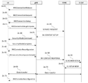
도 1e에서 RRC 유휴 모드(RRC idle mode) 혹은 RRC 비활성화 모드(RRC inactive mode)에 있는 단말(1e-05)은 소정의 이유(예를 들면 전송할 데이터가 있어서 혹은 페이징 메시지를 수신해서 혹은 트래킹 영역을 갱신하기 위해서 등)로 RRC 연결 모드로 천이하기 위해서 네트워크와 연결을 시도할 수 있다. 따라서 단말은 랜덤 액세스의 첫 번째 절차로 프리앰블을 기지국에게 전송할 수 있다(1e-10). 그리고 기지국이 단말의 프로앰블을 성공적으로 수신한다면 해당 단말에게 랜덤 액세스 응답(RAR, Random Access Response)를 보낼 수 있다. 이 때 기지국은 상기 랜덤 액세스 응답으로 단말에게 빠른 주파수 측정을 지시하는 지시자(indication)를 포함하여 전송할 수 있다. 또한, 상기 랜덤 액세스 응답 메시지에 어떤 주파수들 혹은 어떤 주파수 밴드들을 측정할 것인지(예를 들면 주파수 리스트), 각 주파수 별 우선순위를 설정해주어 어떤 순서로 측정을 할 것인지, 주파수를 측정할 때 주파수의 세기를 어떤 필터링 방법으로 측정할 것인지(예를 들면 L1 필터링, L2 필터링, L3 필터링 방법, 혹은 어떤 계수를 이용하여, 어떤 계산 방법으로 측정할 것인지 등), 주파수를 측정할 때 어떤 이벤트 혹은 조건에 따라서 측정을 시작할 것인지, 현재 서빙 셀(혹은 현재 캠프온 하고 있는 주파수)와 비교했을 때 어떤 기준으로 측정을 할 것인지, 어떤 이벤트 혹은 조건에 따라서 측정한 주파수 결과를 보고할 것인지, 현재 서빙 셀(혹은 현재 캠프온 하고 있는 주파수)와 비교했을 때 어떤 기준 혹은 조건을 만족해야 주파수를 보고할 것인지, 어떤 주기마다 주파수 측정 결과를 보고할 것인지 등의 주파수 측정 설정 정보(early measurement setup)를 포함하여 설정해줄 수 있다. The terminal 1e-05 in the RRC idle mode or the RRC inactive mode in FIG. 1e can not receive the paging message or receive the paging message for a predetermined reason (for example, To update the RRC connection mode, etc.). Accordingly, the UE can transmit the preamble to the Node B as a first procedure of the random access (1e-10). If the base station successfully receives the UE's promamble, it can send a random access response (RAR) to the UE. At this time, the BS may transmit an indication indicating the fast frequency measurement to the UE in the random access response. In addition, it is possible to determine which frequencies or certain frequency bands are to be measured in the random access response message (for example, a frequency list), a priority order for each frequency, (Eg, L1 filtering, L2 filtering, L3 filtering, or what factors are used to measure with some calculation method), and what events or conditions It is therefore important to decide whether to start the measurement, what criteria to measure relative to the current serving cell (or the current camp-on frequency), what frequency event to report according to which event or condition, The frequency that is currently camped on) should be met. And an early measurement setup information such as the frequency measurement result to be reported every cycle.
또 다른 방법으로 기지국은 상기 주파수 측정 관련 설정 정보들을 시스템 정보에서 방송하고, 상기 랜덤 액세스 응답 메시지에서는 빠른 주파수 측정을 지시하는 지시자만을 포함하여 단말에게 지시할 수 있다. Alternatively, the base station broadcasts the frequency measurement-related setting information in the system information, and in the random access response message, the base station may include only an indicator for instructing quick frequency measurement.
또 다른 방법으로 기지국은 단말에게 RRC 유휴 모드에서 셀 재선택시 측정하는 주파수 측정 관련 설정 정보(예를 들면 주파수 리스트, 주파수 별 우선 순위 등)을 재사용하도록 하고, 상기 랜덤 액세스 응답 메시지에서는 빠른 주파수 측정을 지시하는 지시자만을 포함하여 단말에게 지시할 수 있다. Alternatively, the base station may reuse the frequency measurement related setting information (e.g., frequency list, frequency priority, and the like) measured at the time of cell reselection in the RRC idle mode to the UE. In the random access response message, It is possible to instruct the terminal to include only the indicator indicating the terminal.
상기에서 단말이 빠른 주파수 측정(early measurement)을 수행할 때 주파수 측정을 시작하는 조건은 다음과 같을 수 있다. The conditions for starting the frequency measurement when the UE performs early measurement may be as follows.
1. RRC 유휴모드 혹은 RRC 비활성 모드로 진입하였을 때 One. When entering RRC idle mode or RRC disable mode
2. 상기에서 주파수 측정 관련 설정 정보들을 수신하였을 때 2. When the frequency measurement related setting information is received
3. 상기에서 랜덤 액세스 응답(RAR) 메시지로 빠른 주파수 측정 지시자를 수신하고 확인하였을 때 3. When the fast frequency measurement indicator is received and confirmed in the RAR message,
4. 랜덤 액세스 절차에서 프리앰블을 전송하였을 때, 즉, 랜덤 액세스 절차를 시작했을 때 4. When a random access procedure transmits a preamble, that is, when a random access procedure is started
5. 단말에서 전송하고자 하는 데이터의 양이 일정 문턱치 값보다 많아졌을 때 5. When the amount of data to be transmitted from the terminal exceeds a predetermined threshold value
상기와 같은 조건 중에 하나 혹은 복수 개의 조건에 따라서 단말은 빠른 주파수 측정(early measurement)을 시작할 수 있다. 단말은 주파수 측정을 수행하면서 메시지 3(예를 들면 RRC Connection Request 혹은 RRC Connection Resume 메시지)를 기지국에게 보내고(1e-25), 이에 대한 응답으로 기지국으로부터 메시지 4(예를 들면 RRC Connection Setup 혹은 RRC Connection Resume 메시지)를 수신하여 랜덤 액세스 절차에 성공하였음을 알 수 있고(1e-30) RRC 연결 모드로 천이할 수 있다(1e-35). 상기에서 단말은 메시지 5(예를 들면 RRC Connection Setup Complete 혹은 RRC Connection Resume Complete)를 보낼 때에 빠른 주파수 측정(early measurement)을 수행하였고, 보고할 주파수 측정 결과가 있다는 지시자를 포함하여 전송할 수 있다. 상기 메시지 5에서 지시자는 빠른 주파수 측정 결과가 있다는 것을 지시하기 위해 새로운 지시자가 정의될 수 있으며, RRC 메시지(RRC Connection Setup Complete 혹은 RRC Connection Resume Complete)에 이미 정의되어 있는 rlf-InfoAvailable-r10(RLF가 발생하였고, 보고할 정보가 있음을 알리는 지시자) 혹은 logMeasAvailable-r10(측정한 정보가 있음을 알리는 지시자)를 재사용할 수도 있다(1e-40). According to one or more of the above conditions, the UE can start early measurement. The UE sends a message 3 (for example, RRC Connection Request or RRC Connection Resume message) to the base station (1e-25) while performing frequency measurement and transmits a message 4 (for example, RRC Connection Setup or RRC Connection (1e-30) and transits to the RRC connection mode (1e-35). The UE may perform an early measurement when transmitting a message 5 (for example, RRC Connection Setup Complete or RRC Connection Resume Complete), and may transmit an indicator indicating that there is a frequency measurement result to be reported. In the
기지국은 상기 메시지 5에서 단말에 빠른 주파수 측정을 수행하였고, 이를 보고할 측정 결과가 있다는 것을 지시자로 확인하면 주파수 측정 결과를 빠르게 보고 받기 위해 측정 결과를 보고하라는 메시지를 단말에게 보낼 수 있다(1e-45). 예를 들면 기지국은 DL-DCCH 메시지로 UEinformationRequest를 이용하여 단말에게 주파수 측정 결과 정보를 요청할 수 있다. 상기 메시지를 수신하면 단말은 빠른 주파수 측정 결과(early measurement)를 빠르게 기지국에게 보고할 수 있다(fast measurement report, 1e-45). 예를 들면 단말은 상기 메시지를 수신하면 UL-DCCH 메시지로 measurementReport를 이용해서 주파수 측정 결과를 보고할 수 있다. 상기에서 주파수 측정 결과는 서빙 셀/주파수 측정 결과(예를 들면 NR-SS RSRP), 서빙 셀/주파수의 주변 셀/주파수 측정 결과, 단말이 측정이 가능한 주변 셀/주파수 측정 결과, 측정하라고 지시한 셀/주파수 측정 결과 등을 포함할 수 있다. The base station performs fast frequency measurement to the terminal in the
상기에서 단말이 빠른 주파수 측정(early measurement)을 중지할 조건은 다음과 같을 수 있다. The condition for the terminal to stop early measurement may be as follows.
1.
메시지 5을 전송한 후, One.
After sending
2. 기지국으로부터 주파수 측정 결과를 보고하라는 메시지 혹은 명령을 받은 후,2. After receiving a message or command to report the frequency measurement result from the base station,
3. 기지국에게 주파수 측정 결과를 보고하기 위한 메시지를 구성한 후,3. After constructing a message to report the frequency measurement result to the base station,
4. 기지국에게 주파수 측정 결과를 보고하기 위한 메시지를 보낸 후,4. After sending a message to the base station to report the frequency measurement result,
5. 랜덤 액세스에서 실패했을 경우,5. If random access fails,
6. 기지국이 단말에게 RRC 메시지로 빠른 주파수 측정(early measurement)을 중지하라고 명시적으로 지시한 경우, 예를 들면 RRC Connection Setup 메시지 혹은 RRC Connection Resume 메시지에서 지시자로 지시.6. If the BS explicitly instructs the UE to suspend early measurement in the RRC message, for example, the RRC Connection Setup message or the RRC Connection Resume message instructs the UE to indicate an early measurement.
상기 중에 하나 혹은 복수 개의 조건에 따라 단말은 빠른 주파수 측정(early measurement)을 중지할 수 있다(1e-50). According to one or more of the above conditions, the UE can stop early measurement (1e-50).
상기에서 단말은 빠른 주파수 설정 관련 정보에서 자신이 측정할 수 있는 즉, 지원하는 주파수들에 대해서 측정을 수행하며, 이 때 단말은 소정의 설정된 우선 순위에 따라서 우선적으로 측정을 수행할 주파수를 선택할 수도 있다. In this case, the terminal measures the frequencies that it can measure, that is, the supported frequencies, from the fast frequency setting related information. In this case, the terminal may preferentially select a frequency to perform measurement according to a predetermined priority order have.
또한 상기에서 단말은 빠른 주파수 측정(early measurement)를 수행 시에 contention resolution에 실패하면 프리앰블 전송으로 복귀하여 랜덤 액세스 절차를 다시 수행할 수 있으며, 이후에는 수신한 랜덤 액세스 응답에 빠른 주파수 측정 지시자 혹은 주파수 설정 관련 정보가 없더라도 계속하여 빠른 주파수 측정(early measurement)을 수행할 수 있다. If the contention resolution fails in performing early measurement, the UE returns to the preamble transmission and can perform the random access procedure again. Thereafter, the UE may perform a fast frequency measurement indicator or frequency Even if there is no information related to the setting, it is possible to carry out an early measurement.
또한 상기에서 단말은 랜덤 액세스 절차에 실패하면 빠른 주파수 측정(early measurement)을 중지할 수 있다. In addition, the UE can stop early measurement if the random access procedure fails.
또한 상기에서 단말은 현재 서빙 셀 혹은 주파수에 대해서는 빠른 주파수 측정을 하라는 지시를 하지 않더라도 빠른 주파수 측정을 수행할 수 있다.Also, the UE can perform fast frequency measurement without instructing the UE to perform fast frequency measurement on the serving cell or the frequency.
도 1f는 본 발명의 차세대 이동 통신 시스템에서 단말이 일찍 주파수 측정(early measurement)을 수행할 수 있도록 하고, 빠르게 주파수 측정 결과를 보고(fast measurement report)할 수 있도록 하는 제 1-2 실시 예를 나타낸 도면이다. FIG. 1F shows a first embodiment in which the UE can perform early measurement in a next generation mobile communication system and can quickly report a frequency measurement (fast measurement report). FIG.
제 1-2 실시 예에서 빠른 주파수 측정(early measurement)을 수행하고 빠르게 주파수 측정 결과(fast measurement report)를 보고할 수 있는 단말은 다음과 같은 경우 중에 하나 혹은 복수 개에 해당하는 단말일 수 있다. A terminal capable of performing early measurement and reporting a fast measurement report in the embodiment 1-2 may be one or more of the following cases.
1. 단말의 Capability 가 빠른 주파수 측정 및 빠른 주파수 측정 결과 보고 방법을 지원하는 모든 단말One. All terminals supporting fast frequency measurement and fast frequency measurement report method
2. RRC 비활성화 모드 단말 중에서 기지국이 RRC 메시지로 상기 단말을 RRC 연결 모드에서 RRC 비활성화 모드로 천이시킬 때 빠른 주파수 측정 및 빠른 주파수 측정 결과 보고를 수행할 수 있도록 지정한 단말(예를 들면 지시자로).2. RRC deactivation mode A terminal (for example, as an indicator) designated to be able to perform fast frequency measurement and quick frequency measurement result report when the base station transits the terminal from the RRC connection mode to the RRC deactivation mode in the RRC message.
3. MO(Mobile Oriented) 데이터가 발생한 단말, 즉 상향 링크 전송할 데이터가 존재하는 단말3. In a terminal in which MO (Mobile Oriented) data is generated, i.e., a terminal in which data to be transmitted in uplink exists
4. MT(Mobile Terminated) 데이터가 네트워크에서 발생하여(즉, 하향 링크 데이터가 발생) 네트워크로부터 페이징 메시지를 수신하였고, 페이징 메시지에서 빠른 주파수 측정 및 빠른 주파수 측정 결과 보고를 수행할 수 있도록 지정한 단말(예를 들면 지시자로).4. (E.g., mobile terminated) data is generated in the network (i.e., downlink data is generated), the paging message is received from the network, and the paging message is used to perform fast frequency measurement and quick frequency measurement report, As an indicator).
5. RRC 유휴 모드 단말 혹은 RRC 비활성화 모드 단말 중에 전송할 데이터의 양이 일정 문턱치(threshold)보다 많은 경우, 상기 문턱치는 기지국에서 RRC 메시지로 설정해주거나 시스템 정보에서 방송할 수 있다. 상기 RRC 메시지는 RRC 연결 모드에서 RRC 유휴 모드 혹은 RRC 비활성화 모드로 천이하는 메시지 혹은 단말이 이전 접속을 설정할 때 수신할 수 있는 RRC 메시지가 될 수 있다. 5. If the amount of data to be transmitted to the RRC idle mode terminal or the RRC deactivated mode terminal is greater than a predetermined threshold, the threshold value may be set as an RRC message in the base station or broadcast in the system information. The RRC message may be a message that transits from the RRC connection mode to the RRC idle mode or the RRC deactivation mode, or an RRC message that the UE can receive when establishing the previous connection.
6. RRC 비활성화 모드 단말 중에서 기지국이 RRC 메시지로 상기 단말을 RRC 연결 모드에서 RRC 비활성화 모드로 천이시킬 때 특정 페이징 영역에 있을 때는 빠른 주파수 측정 및 빠른 주파수 측정 결과 보고를 수행할 수 있도록 지정한 단말(예를 들면 지시자로)이고 상기 설정된 페이징 영역에 있는 단말.6. RRC deactivation mode When a base station transitions from the RRC connection mode to the RRC deactivation mode in the RRC message, the base station can perform fast frequency measurement and report a fast frequency measurement result when it is in a specific paging area And the terminal in the paging area.
도 1f에서 RRC 유휴 모드(RRC idle mode) 혹은 RRC 비활성화 모드(RRC inactive mode)에 있는 단말(1f-05)은 소정의 이유(예를 들면 전송할 데이터가 있어서 혹은 페이징 메시지를 수신해서 혹은 트래킹 영역을 갱신하기 위해서 등)로 RRC 연결 모드로 천이하기 위해서 네트워크와 연결을 시도할 수 있다. 단말은 연결을 시도하기 전에 시스템 정보를 읽을 수 있다(1f-10). 상기 시스템 정보에는 빠른 주파수 측정(early measurement)을 수행할 때 어떤 주파수들 혹은 어떤 주파수 밴드들을 측정할 것인지(예를 들면 주파수 리스트), 각 주파수 별 우선순위를 설정해주어 어떤 순서로 측정을 할 것인지, 주파수를 측정할 때 주파수의 세기를 어떤 필터링 방법으로 측정할 것인지(예를 들면 L1 필터링, L2 필터링, L3 필터링 방법, 혹은 어떤 계수를 이용하여, 어떤 계산 방법으로 측정할 것인지 등), 주파수를 측정할 때 어떤 이벤트 혹은 조건에 따라서 측정을 시작할 것인지, 현재 서빙 셀(혹은 현재 캠프온 하고 있는 주파수)와 비교했을 때 어떤 기준으로 측정을 할 것인지, 어떤 이벤트 혹은 조건에 따라서 측정한 주파수 결과를 보고할 것인지, 현재 서빙 셀(혹은 현재 캠프온 하고 있는 주파수)와 비교했을 때 어떤 기준 혹은 조건을 만족해야 주파수를 보고할 것인지, 어떤 주기마다 주파수 측정 결과를 보고할 것인지 등의 주파수 측정 설정 정보(early measurement setup)를 포함하여 설정해줄 수 있다. The terminal 1f-05 in the RRC idle mode or the RRC inactive mode in FIG. 1F may transmit the paging message to the terminal 1f-05 for a predetermined reason (for example, To update the RRC connection mode, etc.). The terminal can read the system information before attempting to connect (1f-10). The system information includes information on which frequencies or which frequency bands are to be measured (for example, a frequency list) when performing early measurement, a priority order for each frequency, When measuring the frequency, it is necessary to determine how to measure the frequency intensity by the filtering method (for example, L1 filtering, L2 filtering, L3 filtering method, or which coefficient is used and which calculation method is used) The frequency response measured according to an event or condition, the frequency at which the measurement is to be started according to an event or condition, the frequency at which the current serving cell (or currently camped frequency) is compared (Or the frequency at which the current cell is currently camped) Should I want to see the frequency, which cycles every want to report the frequency measurements can be set to give a frequency measurement configuration information (early measurement setup) and the like.
상기 주파수 측정 설정 정보를 확인하면 단말은 랜덤 액세스의 첫 번째 절차로 프리앰블을 기지국에게 전송할 수 있다(1f-20). 그리고 기지국이 단말의 프로앰블을 성공적으로 수신한다면 해당 단말에게 랜덤 액세스 응답(RAR, Random Access Response)를 보낼 수 있다(1f-25). 이 때 기지국은 상기 랜덤 액세스 응답으로 단말에게 빠른 주파수 측정을 지시하는 지시자(indication)를 포함하여 전송할 수 있다. 혹은 상기 랜덤 액세스 응답 메시지에서 지시자가 없더라도 단말은 상기 시스템 정보에서 수신한 주파수 측정 설정 정보를 토대로 빠른 주파수 측정을 시작할 수 있다. Upon confirming the frequency measurement setup information, the UE can transmit a preamble to the Node B as a first procedure of random access (1f-20). If the base station successfully receives the UE's promamble, it can send a random access response (RAR) to the UE (1f-25). At this time, the BS may transmit an indication indicating the fast frequency measurement to the UE in the random access response. Alternatively, the UE may start fast frequency measurement based on the frequency measurement setting information received from the system information even if there is no indicator in the random access response message.
상기에서 단말이 빠른 주파수 측정(early measurement)을 수행할 때 주파수 측정을 시작하는 조건은 다음과 같을 수 있다. The conditions for starting the frequency measurement when the UE performs early measurement may be as follows.
1. RRC 유휴모드 혹은 RRC 비활성 모드로 진입하였을 때 One. When entering RRC idle mode or RRC disable mode
2. 상기에서 시스템 정보로 주파수 측정 관련 설정 정보들을 수신하였을 때 2. When the frequency measurement related setting information is received from the system information
3. 상기에서 랜덤 액세스 응답(RAR) 메시지로 빠른 주파수 측정 지시자를 수신하고 확인하였을 때 3. When the fast frequency measurement indicator is received and confirmed in the RAR message,
4. 랜덤 액세스 절차에서 프리앰블을 전송하였을 때, 즉, 랜덤 액세스 절차를 시작했을 때4. When a random access procedure transmits a preamble, that is, when a random access procedure is started
5. 단말에서 전송하고자 하는 데이터의 양이 일정 문턱치 값보다 많아졌을 때 5. When the amount of data to be transmitted from the terminal exceeds a predetermined threshold value
상기와 같은 조건 중에 하나 혹은 복수 개의 조건에 따라서 단말은 빠른 주파수 측정(early measurement)을 시작할 수 있다. 단말은 주파수 측정을 수행하면서 메시지 3(예를 들면 RRC Connection Request 혹은 RRC Connection Resume 메시지)를 기지국에게 보내고(1f-30), 이에 대한 응답으로 기지국으로부터 메시지 4(예를 들면 RRC Connection Setup 혹은 RRC Connection Resume 메시지)를 수신하여 랜덤 액세스 절차에 성공하였음을 알 수 있고(1f-35) RRC 연결 모드로 천이할 수 있다(1f-40). 상기에서 단말은 메시지 5(예를 들면 RRC Connection Setup Complete 혹은 RRC Connection Resume Complete)를 보낼 때에 빠른 주파수 측정(early measurement)을 수행하였고, 보고할 주파수 측정 결과가 있다는 지시자를 포함하여 전송할 수 있다. 상기 메시지 5에서 지시자는 빠른 주파수 측정 결과가 있다는 것을 지시하기 위해 새로운 지시자가 정의될 수 있으며, RRC 메시지(RRC Connection Setup Complete 혹은 RRC Connection Resume Complete)에 이미 정의되어 있는 rlf-InfoAvailable-r10 (RLF가 발생하였고, 보고할 정보가 있음을 알리는 지시자) 혹은 logMeasAvailable-r10 (측정한 정보가 있음을 알리는 지시자)를 재사용할 수도 있다(1f-45). According to one or more of the above conditions, the UE can start early measurement. The UE sends a message 3 (for example, an RRC Connection Request or an RRC Connection Resume message) to the base station while performing frequency measurement (1f-30), and transmits a message 4 (for example, RRC Connection Setup or RRC Connection (1f-35) and transits to the RRC connection mode (1f-40). The UE may perform an early measurement when transmitting a message 5 (for example, RRC Connection Setup Complete or RRC Connection Resume Complete), and may transmit an indicator indicating that there is a frequency measurement result to be reported. In the
기지국은 상기 메시지 5에서 단말에 빠른 주파수 측정을 수행하였고, 이를 보고할 측정 결과가 있다는 것을 지시자로 확인하면 주파수 측정 결과를 빠르게 보고 받기 위해 측정 결과를 보고하라는 메시지를 단말에게 보낼 수 있다(1f-50). 예를 들면 기지국은 DL-DCCH 메시지로 UEinformationRequest를 이용하여 단말에게 주파수 측정 결과 정보를 요청할 수 있다. 상기 메시지를 수신하면 단말은 빠른 주파수 측정 결과(early measurement)를 빠르게 기지국에게 보고할 수 있다(fast measurement report, 1f-60). 예를 들면 단말은 상기 메시지를 수신하면 UL-DCCH 메시지로 measurementReport를 이용해서 주파수 측정 결과를 보고할 수 있다. 상기에서 주파수 측정 결과는 서빙 셀/주파수 측정 결과(예를 들면 NR-SS RSRP), 서빙 셀/주파수의 주변 셀/주파수 측정 결과, 단말이 측정이 가능한 주변 셀/주파수 측정 결과, 측정하라고 지시한 셀/주파수 측정 결과 등을 포함할 수 있다. The base station performs fast frequency measurement to the terminal in the
상기에서 단말이 빠른 주파수 측정(early measurement)을 중지할 조건은 다음과 같을 수 있다. The condition for the terminal to stop early measurement may be as follows.
1.
메시지 5을 전송한 후, One.
After sending
2. 기지국으로부터 주파수 측정 결과를 보고하라는 메시지 혹은 명령을 받은 후,2. After receiving a message or command to report the frequency measurement result from the base station,
3. 기지국에게 주파수 측정 결과를 보고하기 위한 메시지를 구성한 후,3. After constructing a message to report the frequency measurement result to the base station,
4. 기지국에게 주파수 측정 결과를 보고하기 위한 메시지를 보낸 후,4. After sending a message to the base station to report the frequency measurement result,
5. 랜덤 액세스에서 실패했을 경우,5. If random access fails,
6. 기지국이 단말에게 RRC 메시지로 빠른 주파수 측정(early measurement)을 중지하라고 명시적으로 지시한 경우, 예를 들면 RRC Connection Setup 메시지 혹은 RRC Connection Resume 메시지에서 지시자로 지시.6. If the BS explicitly instructs the UE to suspend early measurement in the RRC message, for example, the RRC Connection Setup message or the RRC Connection Resume message instructs the UE to indicate an early measurement.
상기 중에 하나 혹은 복수 개의 조건에 따라 단말은 빠른 주파수 측정(early measurement)을 중지할 수 있다(1f-55). According to one or more of the above conditions, the terminal can stop early measurement (1f-55).
상기에서 단말은 빠른 주파수 설정 관련 정보에서 자신이 측정할 수 있는 즉, 지원하는 주파수들에 대해서 측정을 수행하며, 이 때 단말은 소정의 설정된 우선 순위에 따라서 우선적으로 측정을 수행할 주파수를 선택할 수도 있다. In this case, the terminal measures the frequencies that it can measure, that is, the supported frequencies, from the fast frequency setting related information. In this case, the terminal may preferentially select a frequency to perform measurement according to a predetermined priority order have.
또한 상기에서 단말은 빠른 주파수 측정(early measurement)를 수행 시에 contention resolution에 실패하면 프리앰블 전송으로 복귀하여 랜덤 액세스 절차를 다시 수행할 수 있으며, 이후에는 수신한 랜덤 액세스 응답에 빠른 주파수 측정 지시자 혹은 주파수 설정 관련 정보가 없더라도 계속하여 빠른 주파수 측정(early measurement)을 수행할 수 있다. If the contention resolution fails in performing early measurement, the UE returns to the preamble transmission and can perform the random access procedure again. Thereafter, the UE may perform a fast frequency measurement indicator or frequency Even if there is no information related to the setting, it is possible to carry out an early measurement.
또한 상기에서 단말은 랜덤 액세스 절차에 실패하면 빠른 주파수 측정(early measurement)을 중지할 수 있다. In addition, the UE can stop early measurement if the random access procedure fails.
또한 상기에서 단말은 현재 서빙 셀 혹은 주파수에 대해서는 빠른 주파수 측정을 하라는 지시를 하지 않더라도 빠른 주파수 측정을 수행할 수 있다.Also, the UE can perform fast frequency measurement without instructing the UE to perform fast frequency measurement on the serving cell or the frequency.
도 1g는 본 발명의 차세대 이동 통신 시스템에서 단말이 일찍 주파수 측정(early measurement)을 수행할 수 있도록 하고, 빠르게 주파수 측정 결과를 보고(fast measurement report)할 수 있도록 하는 제 1-3 실시 예를 나타낸 도면이다. FIG. 1G shows a first to third embodiments in which a UE can perform early measurement in a next generation mobile communication system and can quickly report a frequency measurement (fast measurement report). FIG.
제 1-3 실시 예에서 빠른 주파수 측정(early measurement)을 수행하고 빠르게 주파수 측정 결과(fast measurement report)를 보고할 수 있는 단말은 다음과 같은 경우 중에 하나 혹은 복수 개에 해당하는 단말일 수 있다. In the first to third embodiments, a terminal capable of performing early measurement and reporting a fast measurement report may be one or more of the following cases.
1. 단말의 Capability 가 빠른 주파수 측정 및 빠른 주파수 측정 결과 보고 방법을 지원하는 모든 단말One. All terminals supporting fast frequency measurement and fast frequency measurement report method
2. RRC 비활성화 모드 단말 중에서 기지국이 RRC 메시지로 상기 단말을 RRC 연결 모드에서 RRC 비활성화 모드로 천이시킬 때 빠른 주파수 측정 및 빠른 주파수 측정 결과 보고를 수행할 수 있도록 지정한 단말(예를 들면 지시자로).2. RRC deactivation mode A terminal (for example, as an indicator) designated to be able to perform fast frequency measurement and quick frequency measurement result report when the base station transits the terminal from the RRC connection mode to the RRC deactivation mode in the RRC message.
3. MO(Mobile Oriented) 데이터가 발생한 단말, 즉 상향 링크 전송할 데이터가 존재하는 단말3. In a terminal in which MO (Mobile Oriented) data is generated, i.e., a terminal in which data to be transmitted in uplink exists
4. MT(Mobile Terminated) 데이터가 네트워크에서 발생하여(즉, 하향 링크 데이터가 발생) 네트워크로부터 페이징 메시지를 수신하였고, 페이징 메시지에서 빠른 주파수 측정 및 빠른 주파수 측정 결과 보고를 수행할 수 있도록 지정한 단말(예를 들면 지시자로).4. (E.g., mobile terminated) data is generated in the network (i.e., downlink data is generated), the paging message is received from the network, and the paging message is used to perform fast frequency measurement and quick frequency measurement report, As an indicator).
5. RRC 유휴 모드 단말 혹은 RRC 비활성화 모드 단말 중에 전송할 데이터의 양이 일정 문턱치(threshold)보다 많은 경우, 상기 문턱치는 기지국에서 RRC 메시지로 설정해주거나 시스템 정보에서 방송할 수 있다. 상기 RRC 메시지는 RRC 연결 모드에서 RRC 유휴 모드 혹은 RRC 비활성화 모드로 천이하는 메시지 혹은 단말이 이전 접속을 설정할 때 수신할 수 있는 RRC 메시지가 될 수 있다. 5. If the amount of data to be transmitted to the RRC idle mode terminal or the RRC deactivated mode terminal is greater than a predetermined threshold, the threshold value may be set as an RRC message in the base station or broadcast in the system information. The RRC message may be a message that transits from the RRC connection mode to the RRC idle mode or the RRC deactivation mode, or an RRC message that the UE can receive when establishing the previous connection.
6. RRC 비활성화 모드 단말 중에서 기지국이 RRC 메시지로 상기 단말을 RRC 연결 모드에서 RRC 비활성화 모드로 천이시킬 때 특정 페이징 영역에 있을 때는 빠른 주파수 측정 및 빠른 주파수 측정 결과 보고를 수행할 수 있도록 지정한 단말(예를 들면 지시자로)이고 상기 설정된 페이징 영역에 있는 단말.6. RRC deactivation mode When a base station transitions from the RRC connection mode to the RRC deactivation mode in the RRC message, the base station can perform fast frequency measurement and report a fast frequency measurement result when it is in a specific paging area And the terminal in the paging area.
도 1g에서 RRC 연결 모드에 있는 단말(1g-05)은 소정의 이유(예를 들면 일정한 시간 동안 데이터의 송수신이 없어서 등)로 기지국에 의해서 RRC 유휴 모드(RRC idle mode) 혹은 RRC 비활성화 모드(RRC inactive mode)모드로 천이될 수 있다(1g-15). 상기에서 기지국의 단말의 모드로 전환할 때 RRC 메시지를 보낸다(1g-10). 예를 들면 RRC Connection Release 메시지 혹은 RRC Connection Suspend 메시지가 될 수 있다. 상기 RRC 메시지에는 빠른 주파수 측정(early measurement)을 수행할 때 어떤 주파수들 혹은 어떤 주파수 밴드들을 측정할 것인지(예를 들면 주파수 리스트), 각 주파수 별 우선순위를 설정해주어 어떤 순서로 측정을 할 것인지, 주파수를 측정할 때 주파수의 세기를 어떤 필터링 방법으로 측정할 것인지(예를 들면 L1 필터링, L2 필터링, L3 필터링 방법, 혹은 어떤 계수를 이용하여, 어떤 계산 방법으로 측정할 것인지 등), 주파수를 측정할 때 어떤 이벤트 혹은 조건에 따라서 측정을 시작할 것인지, 현재 서빙 셀(혹은 현재 캠프온 하고 있는 주파수)와 비교했을 때 어떤 기준으로 측정을 할 것인지, 어떤 이벤트 혹은 조건에 따라서 측정한 주파수 결과를 보고할 것인지, 현재 서빙 셀(혹은 현재 캠프온 하고 있는 주파수)와 비교했을 때 어떤 기준 혹은 조건을 만족해야 주파수를 보고할 것인지, 어떤 주기마다 주파수 측정 결과를 보고할 것인지 등의 주파수 측정 설정 정보(early measurement setup)를 포함하여 설정해줄 수 있다. The terminal 1g-05 in the RRC connection mode in FIG. 1G may transmit an RRC idle mode or an RRC deactivation mode (RRC idle mode) by the base station for a predetermined reason (for example, inactive mode (1g-15). When switching to the mode of the terminal of the base station, an RRC message is sent (1g-10). For example, an RRC Connection Release message or an RRC Connection Suspend message. The RRC message includes information on which frequencies or certain frequency bands are to be measured (e.g., a frequency list) when performing early measurement, a priority order for each frequency, When measuring the frequency, it is necessary to determine how to measure the frequency intensity by the filtering method (for example, L1 filtering, L2 filtering, L3 filtering method, or which coefficient is used and which calculation method is used) The frequency response measured according to an event or condition, the frequency at which the measurement is to be started according to an event or condition, the frequency at which the current serving cell (or currently camped frequency) is compared , Or any criteria or condition when compared to the current serving cell (or current camp-on frequency) I want to see the frequency, which cycles every want to report the frequency measurements can be set to give a frequency measurement configuration information (early measurement setup) and the like.
또 다른 방법으로 상기에서 단말의 모드를 전환하는 RRC 메시지에는 상기와 같은 주파수 측정 설정 정보가 포함되지 않고, 빠른 주파수 측정(early measurement)를 지시하는 지시자만 포함할 수 있다. 그리고 주파수 측정 설정 정보는 시스템 정보로부터 수신하거나 RRC 유휴모드에서 셀 재선택을 위해서 사용하는 주파수 측정 정보를 재사용할 수 있다. Alternatively, the RRC message for switching the mode of the UE may not include the frequency measurement setup information, but may include only an indicator for early measurement. And the frequency measurement setup information may be reused from the system information or from the frequency measurement information used for cell reselection in the RRC idle mode.
또 다른 방법으로 상기에서 단말의 모드를 전환하는 RRC 메시지에는 상기와 같은 주파수 측정 설정 정보가 포함되지 않고, 빠른 주파수 측정(early measurement)를 지시하는 지시자와 단말이 RRC 비활성화 모드로 천이될 경우, 소정의 페이징 영역을 설정해주고, 상기 페이징 영역에서만 빠른 주파수 측정을 수행하도록 지시할 수 있다. 그리고 주파수 측정 설정 정보는 시스템 정보로부터 수신하거나 RRC 유휴모드에서 셀 재선택을 위해서 사용하는 주파수 측정 정보를 재사용할 수 있다. Alternatively, the RRC message for switching the mode of the UE may not include the frequency measurement setup information, and may include an indicator for early measurement, and an indicator for indicating an early measurement when the UE transitions to the RRC deactivation mode. And to instruct the user to perform fast frequency measurement only in the paging area. And the frequency measurement setup information may be reused from the system information or from the frequency measurement information used for cell reselection in the RRC idle mode.
또 다른 방법으로 상기에서 단말의 모드를 전환하는 RRC 메시지에는 상기와 같은 주파수 측정 설정 정보가 포함되고, 빠른 주파수 측정(early measurement)를 지시하는 지시자와 단말이 RRC 비활성화 모드로 천이될 경우, 소정의 페이징 영역을 설정해주고, 상기 페이징 영역에서만 빠른 주파수 측정을 수행하도록 지시할 수 있다. Alternatively, the RRC message for switching the mode of the UE may include the frequency measurement setting information as described above, an indicator for early measurement, and an indicator for indicating an early measurement when the UE transitions to the RRC deactivation mode. It is possible to set a paging area and direct the user to perform fast frequency measurement only in the paging area.
상기 주파수 측정 설정 정보를 확인하고 단말은 소정의 이유로 네트워크에 접속할 이유가 생기면 랜덤 액세스의 첫 번째 절차로 프리앰블을 기지국에게 전송할 수 있다(1g-20). 그리고 기지국이 단말의 프로앰블을 성공적으로 수신한다면 해당 단말에게 랜덤 액세스 응답(RAR, Random Access Response)를 보낼 수 있다(1g-25). 이 때 기지국은 상기 랜덤 액세스 응답으로 단말에게 빠른 주파수 측정을 지시하는 지시자(indication)를 포함하여 전송할 수 있다. 혹은 상기 랜덤 액세스 응답 메시지에서 지시자가 없더라도 단말은 상기 시스템 정보에서 수신한 주파수 측정 설정 정보를 토대로 빠른 주파수 측정을 시작할 수 있다. When the UE confirms the frequency measurement setup information and there is a reason to connect to the network for a predetermined reason, the UE can transmit the preamble to the Node B as a first procedure of random access (1g-20). If the base station successfully receives the UE's promamble, it can send a Random Access Response (RAR) to the UE (1g-25). At this time, the BS may transmit an indication indicating the fast frequency measurement to the UE in the random access response. Alternatively, the UE may start fast frequency measurement based on the frequency measurement setting information received from the system information even if there is no indicator in the random access response message.
상기에서 단말이 빠른 주파수 측정(early measurement)을 수행할 때 주파수 측정을 시작하는 조건은 다음과 같을 수 있다(1g-30). The conditions for starting the frequency measurement when the UE performs early measurement may be as follows (1g-30).
1. RRC 유휴모드 혹은 RRC 비활성 모드로 진입하였을 때 One. When entering RRC idle mode or RRC disable mode
2. 상기에서 주파수 측정 관련 설정 정보들을 수신하였을 때 2. When the frequency measurement related setting information is received
3. 상기에서 랜덤 액세스 응답(RAR) 메시지로 빠른 주파수 측정 지시자를 수신하고 확인하였을 때 3. When the fast frequency measurement indicator is received and confirmed in the RAR message,
4. 랜덤 액세스 절차에서 프리앰블을 전송하였을 때, 즉, 랜덤 액세스 절차를 시작했을 때 4. When a random access procedure transmits a preamble, that is, when a random access procedure is started
5. 단말에서 전송하고자 하는 데이터의 양이 일정 문턱치 값보다 많아졌을 때 5. When the amount of data to be transmitted from the terminal exceeds a predetermined threshold value
상기와 같은 조건 중에 하나 혹은 복수 개의 조건에 따라서 단말은 빠른 주파수 측정(early measurement)을 시작할 수 있다. 단말은 주파수 측정을 수행하면서 메시지 3(예를 들면 RRC Connection Request 혹은 RRC Connection Resume 메시지)를 기지국에게 보내고(1g-35), 이에 대한 응답으로 기지국으로부터 메시지 4(예를 들면 RRC Connection Setup 혹은 RRC Connection Resume 메시지)를 수신하여 랜덤 액세스 절차에 성공하였음을 알 수 있고(1g-40) RRC 연결 모드로 천이할 수 있다(1g-45). 상기에서 단말은 메시지 5(예를 들면 RRC Connection Setup Complete 혹은 RRC Connection Resume Complete)를 보낼 때에 빠른 주파수 측정(early measurement)을 수행하였고, 보고할 주파수 측정 결과가 있다는 지시자를 포함하여 전송할 수 있다. 상기 메시지 5에서 지시자는 빠른 주파수 측정 결과가 있다는 것을 지시하기 위해 새로운 지시자가 정의될 수 있으며, RRC 메시지(RRC Connection Setup Complete 혹은 RRC Connection Resume Complete)에 이미 정의되어 있는 rlf-InfoAvailable-r10 (RLF가 발생하였고, 보고할 정보가 있음을 알리는 지시자) 혹은 logMeasAvailable-r10 (측정한 정보가 있음을 알리는 지시자)를 재사용할 수도 있다(1g-50). According to one or more of the above conditions, the UE can start early measurement. The UE sends a message 3 (for example, an RRC Connection Request or an RRC Connection Resume message) to the base station (1g-35) while performing frequency measurement and transmits a message 4 (for example, RRC Connection Setup or RRC Connection (1g-40) and transits to the RRC connection mode (1g-45). The UE may perform an early measurement when transmitting a message 5 (for example, RRC Connection Setup Complete or RRC Connection Resume Complete), and may transmit an indicator indicating that there is a frequency measurement result to be reported. In the
기지국은 상기 메시지 5에서 단말에 빠른 주파수 측정을 수행하였고, 이를 보고할 측정 결과가 있다는 것을 지시자로 확인하면 주파수 측정 결과를 빠르게 보고 받기 위해 측정 결과를 보고하라는 메시지를 단말에게 보낼 수 있다(1g-55). 예를 들면 기지국은 DL-DCCH 메시지로 UEinformationRequest를 이용하여 단말에게 주파수 측정 결과 정보를 요청할 수 있다. 상기 메시지를 수신하면 단말은 빠른 주파수 측정 결과(early measurement)를 빠르게 기지국에게 보고할 수 있다(fast measurement report, 1g-65). 예를 들면 단말은 상기 메시지를 수신하면 UL-DCCH 메시지로 measurementReport를 이용해서 주파수 측정 결과를 보고할 수 있다. 상기에서 주파수 측정 결과는 서빙 셀/주파수 측정 결과(예를 들면 NR-SS RSRP), 서빙 셀/주파수의 주변 셀/주파수 측정 결과, 단말이 측정이 가능한 주변 셀/주파수 측정 결과, 측정하라고 지시한 셀/주파수 측정 결과 등을 포함할 수 있다. The base station performs fast frequency measurement to the terminal in the
상기에서 단말이 빠른 주파수 측정(early measurement)을 중지할 조건은 다음과 같을 수 있다. The condition for the terminal to stop early measurement may be as follows.
1.
메시지 5을 전송한 후, One.
After sending
2. 기지국으로부터 주파수 측정 결과를 보고하라는 메시지 혹은 명령을 받은 후,2. After receiving a message or command to report the frequency measurement result from the base station,
3. 기지국에게 주파수 측정 결과를 보고하기 위한 메시지를 구성한 후,3. After constructing a message to report the frequency measurement result to the base station,
4. 기지국에게 주파수 측정 결과를 보고하기 위한 메시지를 보낸 후,4. After sending a message to the base station to report the frequency measurement result,
5. 랜덤 액세스에서 실패했을 경우,5. If random access fails,
6. 기지국이 단말에게 RRC 메시지로 빠른 주파수 측정(early measurement)을 중지하라고 명시적으로 지시한 경우, 예를 들면 RRC Connection Setup 메시지 혹은 RRC Connection Resume 메시지에서 지시자로 지시.6. If the BS explicitly instructs the UE to suspend early measurement in the RRC message, for example, the RRC Connection Setup message or the RRC Connection Resume message instructs the UE to indicate an early measurement.
상기 중에 하나 혹은 복수 개의 조건에 따라 단말은 빠른 주파수 측정(early measurement)을 중지할 수 있다(1g-60). Depending on one or more of the above conditions, the terminal may stop early measurement (1g-60).
상기에서 단말은 빠른 주파수 설정 관련 정보에서 자신이 측정할 수 있는 즉, 지원하는 주파수들에 대해서 측정을 수행하며, 이 때 단말은 소정의 설정된 우선 순위에 따라서 우선적으로 측정을 수행할 주파수를 선택할 수도 있다. In this case, the terminal measures the frequencies that it can measure, that is, the supported frequencies, from the fast frequency setting related information. In this case, the terminal may preferentially select a frequency to perform measurement according to a predetermined priority order have.
또한 상기에서 단말은 빠른 주파수 측정(early measurement)를 수행 시에 contention resolution에 실패하면 프리앰블 전송으로 복귀하여 랜덤 액세스 절차를 다시 수행할 수 있으며, 이후에는 수신한 랜덤 액세스 응답에 빠른 주파수 측정 지시자 혹은 주파수 설정 관련 정보가 없더라도 계속하여 빠른 주파수 측정(early measurement)을 수행할 수 있다. If the contention resolution fails in performing early measurement, the UE returns to the preamble transmission and can perform the random access procedure again. Thereafter, the UE may perform a fast frequency measurement indicator or frequency Even if there is no information related to the setting, it is possible to carry out an early measurement.
또한 상기에서 단말은 랜덤 액세스 절차에 실패하면 빠른 주파수 측정(early measurement)을 중지할 수 있다. In addition, the UE can stop early measurement if the random access procedure fails.
또한 상기에서 단말은 현재 서빙 셀 혹은 주파수에 대해서는 빠른 주파수 측정을 하라는 지시를 하지 않더라도 빠른 주파수 측정을 수행할 수 있다.Also, the UE can perform fast frequency measurement without instructing the UE to perform fast frequency measurement on the serving cell or the frequency.
도 1e, 도 1f, 도 1g에서 제안한 본 발명의 차세대 이동 통신 시스템에서 단말이 일찍 주파수 측정(early measurement)을 수행할 수 있도록 하고, 빠르게 주파수 측정 결과를 보고(fast measurement report)할 수 있도록 하는 제 1 실시 예, 제 2 실시 예, 제 3 실시 예를 통해 기지국은 빠르게 주파수 측정 결과를 보고 받을 수 있으며, 이를 토대로 기지국은 상기 단말에게 빠르게 주파수 응집 기술 혹은 이중 접속 기술을 설정해줄 수 있다. In the next generation mobile communication system of the present invention proposed in FIG. 1E, FIG. 1F and FIG. 1G, a terminal can perform early measurement and can perform a fast measurement report The base station can quickly report the frequency measurement result through the first embodiment, the second embodiment, and the third embodiment, and the base station can quickly set up a frequency coherence technique or a dual access technique for the UE.
도 1h는 본 발명의 차세대 이동 통신 시스템에서 단말이 일찍 주파수 측정(early measurement)을 수행하고 빠르게 주파수 측정 결과를 보고(fast measurement report)하는 단말 동작을 나타낸 도면이다. FIG. 1H is a diagram illustrating a terminal operation in which the UE performs an early measurement and a fast measurement report in a next generation mobile communication system according to the present invention.
단말(1h-01)은 주파수 측정 설정 정보를 상기 제 1 실시 예 혹은 제 2 실시 예 혹은 제 3 실시 예에서 설명한 바와 같이 랜덤 액세스 응답 메시지 혹은 시스템 정보 혹은 단말의 모드를 전환하는 RRC 메시지 혹은 단말의 RRC 유휴모드에서 사용하는 셀 재선택을 위한 주파수 측정 설정 정보 재사용 등으로 확인할 수 있다(1h-05). 상기에서 단말은 주파수 측정 설정 정보를 확인하면 상기에서 설명한 바와 같이 다음의 한가지 혹은 복수 개의 조건에 따라 빠른 주파수 측정을 시작할 수 있다(1h-10). The terminal 1h-01 transmits the frequency measurement setting information to the RRC message or the RRC message for switching the mode of the UE or the system information or the random access response message as described in the first embodiment, the second embodiment, It can be confirmed by re-use of frequency measurement setup information for cell reselection used in RRC idle mode (1h-05). If the UE confirms the frequency measurement setup information, the UE can start fast frequency measurement according to one or more of the following conditions (1h-10) as described above.
1. RRC 유휴모드 혹은 RRC 비활성 모드로 진입하였을 때 One. When entering RRC idle mode or RRC disable mode
2. 상기에서 주파수 측정 관련 설정 정보들을 수신하였을 때 2. When the frequency measurement related setting information is received
3. 상기에서 랜덤 액세스 응답(RAR) 메시지로 빠른 주파수 측정 지시자를 수신하고 확인하였을 때 3. When the fast frequency measurement indicator is received and confirmed in the RAR message,
4. 랜덤 액세스 절차에서 프리앰블을 전송하였을 때, 즉, 랜덤 액세스 절차를 시작했을 때 4. When a random access procedure transmits a preamble, that is, when a random access procedure is started
5. 단말에서 전송하고자 하는 데이터의 양이 일정 문턱치 값보다 많아졌을 때 5. When the amount of data to be transmitted from the terminal exceeds a predetermined threshold value
상기에서 주파수 측정을 수행하고 단말은 상기에서 설명한 바와 같이 다음의 한가지 혹은 복수 개의 조건에 따라 빠른 주파수 측정을 중지할 수 있다(1h-15). The UE performs frequency measurement as described above and can stop fast frequency measurement according to one or more of the following conditions (1h-15) as described above.
1.
메시지 5을 전송한 후, One.
After sending
2. 기지국으로부터 주파수 측정 결과를 보고하라는 메시지 혹은 명령을 받은 후,2. After receiving a message or command to report the frequency measurement result from the base station,
3. 기지국에게 주파수 측정 결과를 보고하기 위한 메시지를 구성한 후,3. After constructing a message to report the frequency measurement result to the base station,
4. 기지국에게 주파수 측정 결과를 보고하기 위한 메시지를 보낸 후,4. After sending a message to the base station to report the frequency measurement result,
5. 랜덤 액세스에서 실패했을 경우,5. If random access fails,
6. 기지국이 단말에게 RRC 메시지로 빠른 주파수 측정(early measurement)을 중지하라고 명시적으로 지시한 경우, 예를 들면 RRC Connection Setup 메시지 혹은 RRC Connection Resume 메시지에서 지시자로 지시.6. If the BS explicitly instructs the UE to suspend early measurement in the RRC message, for example, the RRC Connection Setup message or the RRC Connection Resume message instructs the UE to indicate an early measurement.
단말은 빠른 주파수 측정 결과를 완료한 경우, 기지국에게 주파수 측정 결과가 있다는 내용을 지시하고, 기지국이 상기 주파수 측정 결과 정보를 요청하면 이를 기지국에게 전달하여 보고할 수 있다(1h-20). When the UE completes the fast frequency measurement result, it indicates to the base station that the frequency measurement result is present. If the base station requests the frequency measurement result information, the UE transmits the frequency measurement result information to the base station (1h-20).
도 1i에 본 발명의 실시 예가 적용될 수 있는 단말의 구조를 도시하였다. FIG. 1I illustrates a structure of a terminal to which an embodiment of the present invention can be applied.
상기 도면을 참고하면, 상기 단말은 RF(Radio Frequency)처리부(1i-10), 기저대역(baseband)처리부(1i-20), 저장부(1i-30), 제어부(1i-40)를 포함한다.Referring to FIG. 1, the UE includes a Radio Frequency (RF)
상기 RF처리부(1i-10)는 신호의 대역 변환, 증폭 등 무선 채널을 통해 신호를 송수신하기 위한 기능을 수행한다. 즉, 상기 RF처리부(1i-10)는 상기 기저대역처리부(1i-20)로부터 제공되는 기저대역 신호를 RF 대역 신호로 상향 변환한 후 안테나를 통해 송신하고, 상기 안테나를 통해 수신되는 RF 대역 신호를 기저대역 신호로 하향 변환한다. 예를 들어, 상기 RF처리부(1i-10)는 송신 필터, 수신 필터, 증폭기, 믹서(mixer), 오실레이터(oscillator), DAC(digital to analog convertor), ADC(analog to digital convertor) 등을 포함할 수 있다. 상기 도면에서, 하나의 안테나만이 도시되었으나, 상기 단말은 다수의 안테나들을 구비할 수 있다. 또한, 상기 RF처리부(1i-10)는 다수의 RF 체인들을 포함할 수 있다. 나아가, 상기 RF처리부(1i-10)는 빔포밍(beamforming)을 수행할 수 있다. 상기 빔포밍을 위해, 상기 RF처리부(1i-10)는 다수의 안테나들 또는 안테나 요소(element)들을 통해 송수신되는 신호들 각각의 위상 및 크기를 조절할 수 있다. 또한 상기 RF 처리부는 MIMO를 수행할 수 있으며, MIMO 동작 수행 시 여러 개의 레이어를 수신할 수 있다. 상기 RF처리부(1i-10)는 제어부의 제어에 따라 다수의 안테나 또는 안테나 요소들을 적절하게 설정하여 수신 빔 스위핑을 수행하거나, 수신 빔이 송신 빔과 공조되도록 수신 빔의 방향과 빔 너비를 조정할 수 있다.The
상기 기저대역처리부(1i-20)은 시스템의 물리 계층 규격에 따라 기저대역 신호 및 비트열 간 변환 기능을 수행한다. 예를 들어, 데이터 송신 시, 상기 기저대역처리부(1i-20)은 송신 비트열을 부호화 및 변조함으로써 복소 심벌들을 생성한다. 또한, 데이터 수신 시, 상기 기저대역처리부(1i-20)은 상기 RF처리부(1i-10)로부터 제공되는 기저대역 신호를 복조 및 복호화를 통해 수신 비트열을 복원한다. 예를 들어, OFDM(orthogonal frequency division multiplexing) 방식에 따르는 경우, 데이터 송신 시, 상기 기저대역처리부(1i-20)는 송신 비트열을 부호화 및 변조함으로써 복소 심벌들을 생성하고, 상기 복소 심벌들을 부반송파들에 매핑한 후, IFFT(inverse fast Fourier transform) 연산 및 CP(cyclic prefix) 삽입을 통해 OFDM 심벌들을 구성한다. 또한, 데이터 수신 시, 상기 기저대역처리부(1i-20)은 상기 RF처리부(1i-10)로부터 제공되는 기저대역 신호를 OFDM 심벌 단위로 분할하고, FFT(fast Fourier transform) 연산을 통해 부반송파들에 매핑된 신호들을 복원한 후, 복조 및 복호화를 통해 수신 비트열을 복원한다.The
상기 기저대역처리부(1i-20) 및 상기 RF처리부(1i-10)는 상술한 바와 같이 신호를 송신 및 수신한다. 이에 따라, 상기 기저대역처리부(1i-20) 및 상기 RF처리부(1i-10)는 송신부, 수신부, 송수신부 또는 통신부로 지칭될 수 있다. 나아가, 상기 기저대역처리부(1i-20) 및 상기 RF처리부(1i-10) 중 적어도 하나는 서로 다른 다수의 무선 접속 기술들을 지원하기 위해 다수의 통신 모듈들을 포함할 수 있다. 또한, 상기 기저대역처리부(1i-20) 및 상기 RF처리부(1i-10) 중 적어도 하나는 서로 다른 주파수 대역의 신호들을 처리하기 위해 서로 다른 통신 모듈들을 포함할 수 있다. 예를 들어, 상기 서로 다른 무선 접속 기술들은 LTE 망, NR 망 등을 포함할 수 있다. 또한, 상기 서로 다른 주파수 대역들은 극고단파(SHF:super high frequency)(예: 2.5GHz, 5Ghz) 대역, mm파(millimeter wave)(예: 60GHz) 대역을 포함할 수 있다.The
상기 저장부(1i-30)는 상기 단말의 동작을 위한 기본 프로그램, 응용 프로그램, 설정 정보 등의 데이터를 저장한다. 상기 저장부(1i-30)는 상기 제어부(1i-40)의 요청에 따라 저장된 데이터를 제공한다.The
상기 제어부(1i-40)는 상기 단말의 전반적인 동작들을 제어한다. 예를 들어, 상기 제어부(1i-40)는 상기 기저대역처리부(1i-20) 및 상기 RF처리부(1i-10)을 통해 신호를 송수신한다. 또한, 상기 제어부(1i-40)는 상기 저장부(1i-40)에 데이터를 기록하고, 읽는다. 이를 위해, 상기 제어부(1i-40)는 적어도 하나의 프로세서(processor)를 포함할 수 있다. 예를 들어, 상기 제어부(1i-40)는 통신을 위한 제어를 수행하는 CP(communication processor) 및 응용 프로그램 등 상위 계층을 제어하는 AP(application processor)를 포함할 수 있다. The
도 1j는 본 발명의 실시 예가 적용될 수 있는 무선 통신 시스템에서 TRP의 블록 구성을 도시한다.1J illustrates a block diagram of a TRP in a wireless communication system to which an embodiment of the present invention may be applied.
상기 도면에 도시된 바와 같이, 상기 기지국은 RF처리부(1j-10), 기저대역처리부(1j-20), 백홀통신부(1j-30), 저장부(1j-40), 제어부(1j-50)를 포함하여 구성된다.As shown in the figure, the base station includes an
상기 RF처리부(1j-10)는 신호의 대역 변환, 증폭 등 무선 채널을 통해 신호를 송수신하기 위한 기능을 수행한다. 즉, 상기 RF처리부(1j-10)는 상기 기저대역처리부(1j-20)로부터 제공되는 기저대역 신호를 RF 대역 신호로 상향변환한 후 안테나를 통해 송신하고, 상기 안테나를 통해 수신되는 RF 대역 신호를 기저대역 신호로 하향변환한다. 예를 들어, 상기 RF처리부(1j-10)는 송신 필터, 수신 필터, 증폭기, 믹서, 오실레이터, DAC, ADC 등을 포함할 수 있다. 상기 도면에서, 하나의 안테나만이 도시되었으나, 상기 제1접속 노드는 다수의 안테나들을 구비할 수 있다. 또한, 상기 RF처리부(1j-10)는 다수의 RF 체인들을 포함할 수 있다. 나아가, 상기 RF처리부(1j-10)는 빔포밍을 수행할 수 있다. 상기 빔포밍을 위해, 상기 RF처리부(1j-10)는 다수의 안테나들 또는 안테나 요소들을 통해 송수신되는 신호들 각각의 위상 및 크기를 조절할 수 있다. 상기 RF 처리부는 하나 이상의 레이어를 전송함으로써 하향 MIMO 동작을 수행할 수 있다. The
상기 기저대역처리부(1j-20)는 제1무선 접속 기술의 물리 계층 규격에 따라 기저대역 신호 및 비트열 간 변환 기능을 수행한다. 예를 들어, 데이터 송신 시, 상기 기저대역처리부(1j-20)은 송신 비트열을 부호화 및 변조함으로써 복소 심벌들을 생성한다. 또한, 데이터 수신 시, 상기 기저대역처리부(1j-20)은 상기 RF처리부(1j-10)로부터 제공되는 기저대역 신호를 복조 및 복호화를 통해 수신 비트열을 복원한다. 예를 들어, OFDM 방식에 따르는 경우, 데이터 송신 시, 상기 기저대역처리부(1j-20)은 송신 비트열을 부호화 및 변조함으로써 복소 심벌들을 생성하고, 상기 복소 심벌들을 부반송파들에 매핑한 후, IFFT 연산 및 CP 삽입을 통해 OFDM 심벌들을 구성한다. 또한, 데이터 수신 시, 상기 기저대역처리부(1j-20)은 상기 RF처리부(1j-10)로부터 제공되는 기저대역 신호를 OFDM 심벌 단위로 분할하고, FFT 연산을 통해 부반송파들에 매핑된 신호들을 복원한 후, 복조 및 복호화를 통해 수신 비트열을 복원한다. 상기 기저대역처리부(1j-20) 및 상기 RF처리부(1j-10)는 상술한 바와 같이 신호를 송신 및 수신한다. 이에 따라, 상기 기저대역처리부(1j-20) 및 상기 RF처리부(1j-10)는 송신부, 수신부, 송수신부, 통신부 또는 무선 통신부로 지칭될 수 있다.The
상기 통신부(1j-30)는 네트워크 내 다른 노드들과 통신을 수행하기 위한 인터페이스를 제공한다. The
상기 저장부(1j-40)는 상기 주기지국의 동작을 위한 기본 프로그램, 응용 프로그램, 설정 정보 등의 데이터를 저장한다. 특히, 상기 저장부(1j-40)는 접속된 단말에 할당된 베어러에 대한 정보, 접속된 단말로부터 보고된 측정 결과 등을 저장할 수 있다. 또한, 상기 저장부(1j-40)는 단말에게 다중 연결을 제공하거나, 중단할지 여부의 판단 기준이 되는 정보를 저장할 수 있다. 그리고, 상기 저장부(1j-40)는 상기 제어부(1j-50)의 요청에 따라 저장된 데이터를 제공한다.The
상기 제어부(1j-50)는 상기 주기지국의 전반적인 동작들을 제어한다. 예를 들어, 상기 제어부(1j-50)는 상기 기저대역처리부(1j-20) 및 상기 RF처리부(1j-10)을 통해 또는 상기 백홀통신부(1j-30)을 통해 신호를 송수신한다. 또한, 상기 제어부(1j-50)는 상기 저장부(1j-40)에 데이터를 기록하고, 읽는다. 이를 위해, 상기 제어부(1j-50)는 적어도 하나의 프로세서를 포함할 수 있다. The
<제2실시예>≪
이하 첨부된 도면을 참조하여 본 발명의 동작 원리를 상세히 설명한다. 하기에서 본 발명을 설명하기에 있어 관련된 공지 기능 또는 구성에 대한 구체적인 설명이 본 발명의 요지를 불필요하게 흐릴 수 있다고 판단되는 경우에는 그 상세한 설명을 생략할 것이다. 그리고 후술되는 용어들은 본 발명에서의 기능을 고려하여 정의된 용어들로서 이는 사용자, 운용자의 의도 또는 관례 등에 따라 달라질 수 있다. 그러므로 그 정의는 본 명세서 전반에 걸친 내용을 토대로 내려져야 할 것이다.Hereinafter, the operation principle of the present invention will be described in detail with reference to the accompanying drawings. DETAILED DESCRIPTION OF THE PREFERRED EMBODIMENTS Hereinafter, a detailed description of known functions and configurations incorporated herein will be omitted when it may make the subject matter of the present invention rather unclear. The following terms are defined in consideration of the functions of the present invention, and these may be changed according to the intention of the user, the operator, or the like. Therefore, the definition should be based on the contents throughout this specification.
하기에서 본 발명을 설명함에 있어 관련된 공지 기능 또는 구성에 대한 구체적인 설명이 본 발명의 요지를 불필요하게 흐릴 수 있다고 판단되는 경우에는 그 상세한 설명을 생략할 것이다. 이하 첨부된 도면을 참조하여 본 발명의 실시 예를 설명하기로 한다.In the following description of the present invention, a detailed description of known functions and configurations incorporated herein will be omitted when it may make the subject matter of the present invention rather unclear. DESCRIPTION OF THE PREFERRED EMBODIMENTS Hereinafter, embodiments of the present invention will be described with reference to the accompanying drawings.
이하 설명에서 사용되는 접속 노드(node)를 식별하기 위한 용어, 망 객체(network entity)들을 지칭하는 용어, 메시지들을 지칭하는 용어, 망 객체들 간 인터페이스를 지칭하는 용어, 다양한 식별 정보들을 지칭하는 용어 등은 설명의 편의를 위해 예시된 것이다. 따라서, 본 발명이 후술되는 용어들에 한정되는 것은 아니며, 동등한 기술적 의미를 가지는 대상을 지칭하는 다른 용어가 사용될 수 있다.A term used for identifying a connection node used in the following description, a term referring to network entities, a term referring to messages, a term indicating an interface between network objects, a term indicating various identification information Etc. are illustrated for convenience of explanation. Therefore, the present invention is not limited to the following terms, and other terms referring to objects having equivalent technical meanings can be used.
이하 설명의 편의를 위하여, 본 발명은 3GPP LTE(3rd Generation Partnership Project Long Term Evolution) 규격에서 정의하고 있는 용어 및 명칭들을 사용한다. 하지만, 본 발명이 상기 용어 및 명칭들에 의해 한정되는 것은 아니며, 다른 규격에 따르는 시스템에도 동일하게 적용될 수 있다. 본 발명에서 eNB는 설명의 편의를 위하여 gNB와 혼용되어 사용될 수 있다. 즉 eNB로 설명한 기지국은 gNB를 나타낼 수 있다. For convenience of explanation, the present invention uses terms and names defined in 3GPP LTE (3rd Generation Partnership Project Long Term Evolution) standard. However, the present invention is not limited by the above-mentioned terms and names, and can be equally applied to systems conforming to other standards. In the present invention, eNB can be used in combination with gNB for convenience of explanation. That is, the base station described as an eNB may represent a gNB.
도 2a는 본 발명이 적용될 수 있는 LTE 시스템의 구조를 도시하는 도면이다. 2A is a diagram showing a structure of an LTE system to which the present invention can be applied.
도 2a을 참조하면, 도시한 바와 같이 LTE 시스템의 무선 액세스 네트워크는 차세대 기지국(Evolved Node B, 이하 ENB, Node B 또는 기지국)(2a-05, 2a-10, 2a-15, 2a-20)과 MME (2a-25, Mobility Management Entity) 및 S-GW(2a-30, Serving-Gateway)로 구성된다. 사용자 단말(User Equipment, 이하 UE 또는 단말)(2a-35)은 ENB(2a-05 ~ 2a-20) 및 S-GW(2a-30)를 통해 외부 네트워크에 접속한다.2A, the radio access network of the LTE system includes an Evolved Node B (hereinafter, referred to as an ENB, a Node B or a base station) 2a-05, 2a-10, 2a-15 and 2a-20,
도 2a에서 ENB(2a-05 ~ 2a-20)는 UMTS 시스템의 기존 노드 B에 대응된다. ENB는 UE(2a-35)와 무선 채널로 연결되며 기존 노드 B 보다 복잡한 역할을 수행한다. LTE 시스템에서는 인터넷 프로토콜을 통한 VoIP(Voice over IP)와 같은 실시간 서비스를 비롯한 모든 사용자 트래픽이 공용 채널(shared channel)을 통해 서비스 되므로, UE들의 버퍼 상태, 가용 전송 전력 상태, 채널 상태 등의 상태 정보를 취합해서 스케줄링을 하는 장치가 필요하며, 이를 ENB(2a-05 ~ 2a-20)가 담당한다. 하나의 ENB는 통상 다수의 셀들을 제어한다. 예컨대, 100 Mbps의 전송 속도를 구현하기 위해서 LTE 시스템은 예컨대, 20 MHz 대역폭에서 직교 주파수 분할 다중 방식(Orthogonal Frequency Division Multiplexing, 이하 OFDM이라 한다)을 무선 접속 기술로 사용한다. 또한 단말의 채널 상태에 맞춰 변조 방식(modulation scheme)과 채널 코딩률(channel coding rate)을 결정하는 적응 변조 코딩(Adaptive Modulation & Coding, 이하 AMC라 한다) 방식을 적용한다. S-GW(2a-30)는 데이터 베어러를 제공하는 장치이며, MME(2a-25)의 제어에 따라서 데이터 베어러를 생성하거나 제거한다. MME는 단말에 대한 이동성 관리 기능은 물론 각종 제어 기능을 담당하는 장치로 다수의 기지국 들과 연결된다. In FIG. 2A, the
도 2b는 본 발명이 적용될 수 있는 LTE 시스템에서 무선 프로토콜 구조를 나타낸 도면이다. 2B is a diagram illustrating a wireless protocol structure in an LTE system to which the present invention can be applied.
도 2b를 참조하면, LTE 시스템의 무선 프로토콜은 단말과 ENB에서 각각 PDCP (Packet Data Convergence Protocol 2b-05, 2b-40), RLC (Radio Link Control 2b-10, 2b-35), MAC (Medium Access Control 2b-15, 2b-30)으로 이루어진다. PDCP (Packet Data Convergence Protocol)(2b-05, 2b-40)는 IP 헤더 압축/복원 등의 동작을 담당한다. PDCP의 주요 기능은 하기와 같이 요약된다.Referring to FIG. 2B, the wireless protocol of the LTE system includes PDCP (Packet
- 헤더 압축 및 압축 해제 기능(Header compression and decompression: ROHC only)- Header compression and decompression (ROHC only)
- 사용자 데이터 전송 기능 (Transfer of user data)- Transfer of user data
- 순차적 전달 기능(In-sequence delivery of upper layer PDUs at PDCP re-establishment procedure for RLC AM)- In-sequence delivery of upper layer PDUs at PDCP re-establishment procedure for RLC AM
- 순서 재정렬 기능(For split bearers in DC (only support for RLC AM): PDCP PDU routing for transmission and PDCP PDU reordering for reception)- For split bearers in DC (only support for RLC AM): PDCP PDU routing for transmission and PDCP PDU reordering for reception.
- 중복 탐지 기능(Duplicate detection of lower layer SDUs at PDCP re-establishment procedure for RLC AM)- Duplicate detection of lower layer SDUs at PDCP re-establishment procedure for RLC AM -
- 재전송 기능(Retransmission of PDCP SDUs at handover and, for split bearers in DC, of PDCP PDUs at PDCP data-recovery procedure, for RLC AM)- Retransmission function (PDCP SDUs at handover and for split bearers in DC, PDCP PDUs at PDCP data-recovery procedure, for RLC AM)
- 암호화 및 복호화 기능(Ciphering and deciphering)- Ciphering and deciphering function
- 타이머 기반 SDU 삭제 기능(Timer-based SDU discard in uplink.)- Timer-based SDU discard in uplink.
무선 링크 제어(Radio Link Control, 이하 RLC라고 한다)(2b-10, 2b-35)는 PDCP PDU(Packet Data Unit)를 적절한 크기로 재구성해서 ARQ 동작 등을 수행한다. RLC의 주요 기능은 하기와 같이 요약된다.Radio Link Control (RLC) (2b-10, 2b-35) reconfigures a PDCP PDU (Packet Data Unit) to an appropriate size and performs ARQ operations. The main functions of the RLC are summarized as follows.
- 데이터 전송 기능(Transfer of upper layer PDUs)- Transfer of upper layer PDUs
- ARQ 기능(Error Correction through ARQ (only for AM data transfer))- ARQ function (Error Correction through ARQ (only for AM data transfer))
- 접합, 분할, 재조립 기능(Concatenation, segmentation and reassembly of RLC SDUs (only for UM and AM data transfer))- Concatenation, segmentation and reassembly of RLC SDUs (only for UM and AM data transfer)
- 재분할 기능(Re-segmentation of RLC data PDUs (only for AM data transfer))- Re-segmentation of RLC data PDUs (only for AM data transfer)
- 순서 재정렬 기능(Reordering of RLC data PDUs (only for UM and AM data transfer)- Reordering of RLC data PDUs (only for UM and AM data transfer)
- 중복 탐지 기능(Duplicate detection (only for UM and AM data transfer))- Duplicate detection (only for UM and AM data transfer)
- 오류 탐지 기능(Protocol error detection (only for AM data transfer))- Error detection (only for AM data transfer)
- RLC SDU 삭제 기능(RLC SDU discard (only for UM and AM data transfer))- RLC SDU discard function (RLC SDU discard (only for UM and AM data transfer))
- RLC 재수립 기능(RLC re-establishment)- RLC re-establishment function (RLC re-establishment)
MAC(2b-15, 2b-30)은 한 단말에 구성된 여러 RLC 계층 장치들과 연결되며, RLC PDU들을 MAC PDU에 다중화하고 MAC PDU로부터 RLC PDU들을 역다중화하는 동작을 수행한다. MAC의 주요 기능은 하기와 같이 요약된다.
- 맵핑 기능(Mapping between logical channels and transport channels)- Mapping between logical channels and transport channels.
- 다중화 및 역다중화 기능(Multiplexing/demultiplexing of MAC SDUs belonging to one or different logical channels into/from transport blocks (TB) delivered to/from the physical layer on transport channels)- Multiplexing / demultiplexing of MAC SDUs belonging to one or different logical channels into / from transport blocks (TB) delivered to / from the physical layer on transport channels.
- 스케쥴링 정보 보고 기능(Scheduling information reporting)- Scheduling information reporting function
- HARQ 기능(Error correction through HARQ)- HARQ (Error correction through HARQ)
- 로지컬 채널 간 우선 순위 조절 기능(Priority handling between logical channels of one UE)- Priority handling between logical channels of one UE
- 단말간 우선 순위 조절 기능(Priority handling between UEs by means of dynamic scheduling)- Priority handling between UEs by means of dynamic scheduling
- MBMS 서비스 확인 기능(MBMS service identification)- MBMS service identification (MBMS service identification)
- 전송 포맷 선택 기능(Transport format selection)- Transport format selection function (Transport format selection)
- 패딩 기능(Padding)- Padding function
물리 계층(2b-20, 2b-25)은 상위 계층 데이터를 채널 코딩 및 변조하고, OFDM 심벌로 만들어서 무선 채널로 전송하거나, 무선 채널을 통해 수신한 OFDM 심벌을 복조하고 채널 디코딩해서 상위 계층으로 전달하는 동작을 한다.The
도 2c는 본 발명이 적용될 수 있는 차세대 이동통신 시스템의 구조를 도시하는 도면이다. 2C is a diagram illustrating a structure of a next generation mobile communication system to which the present invention can be applied.
도 2c을 참조하면, 도시한 바와 같이 차세대 이동통신 시스템(이하 NR 혹은 5G)의 무선 액세스 네트워크는 차세대 기지국(New Radio Node B, 이하 NR gNB 혹은 NR 기지국)(2c-10) 과 NR CN (2c-05, New Radio Core Network)로 구성된다. 사용자 단말(New Radio User Equipment, 이하 NR UE 또는 단말)(2c-15)은 NR gNB(2c-10) 및 NR CN (2c-05)를 통해 외부 네트워크에 접속한다.2C, a radio access network of a next generation mobile communication system (hereinafter referred to as NR or 5G) includes a next generation base station (NR gNB or NR base station) 2c-10 and an
도 2c에서 NR gNB(2c-10)는 기존 LTE 시스템의 eNB (Evolved Node B)에 대응된다. NR gNB는 NR UE(2c-15)와 무선 채널로 연결되며 기존 노드 B 보다 더 월등한 서비스를 제공해줄 수 있다. 차세대 이동통신 시스템에서는 모든 사용자 트래픽이 공용 채널(shared channel)을 통해 서비스 되므로, UE들의 버퍼 상태, 가용 전송 전력 상태, 채널 상태 등의 상태 정보를 취합해서 스케줄링을 하는 장치가 필요하며, 이를 NR NB(2c-10)가 담당한다. 하나의 NR gNB는 통상 다수의 셀들을 제어한다. 현재 LTE 대비 초고속 데이터 전송을 구현하기 위해서 기존 최대 대역폭 이상을 가질 수 있고, 직교 주파수 분할 다중 방식(Orthogonal Frequency Division Multiplexing, 이하 OFDM이라 한다)을 무선 접속 기술로 하여 추가적으로 빔포밍 기술이 접목될 수 있다. 또한 단말의 채널 상태에 맞춰 변조 방식(modulation scheme)과 채널 코딩률(channel coding rate)을 결정하는 적응 변조 코딩(Adaptive Modulation & Coding, 이하 AMC라 한다) 방식을 적용한다. NR CN (2c-05)는 이동성 지원, 베어러 설정, QoS 설정 등의 기능을 수행한다. NR CN는 단말에 대한 이동성 관리 기능은 물론 각종 제어 기능을 담당하는 장치로 다수의 기지국 들과 연결된다. 또한 차세대 이동통신 시스템은 기존 LTE 시스템과도 연동될 수 있으며, NR CN이 MME (2c-25)와 네트워크 인터페이스를 통해 연결된다. MME는 기존 기지국인 eNB (2c-30)와 연결된다.In FIG. 2C, the NR gNB (2c-10) corresponds to the eNB (Evolved Node B) of the existing LTE system. The NR gNB is connected to the
도 2d는 본 발명이 적용될 수 있는 차세대 이동통신 시스템의 무선 프로토콜 구조를 나타낸 도면이다. .FIG. 2D is a diagram illustrating a wireless protocol structure of a next generation mobile communication system to which the present invention can be applied. .
도 2d를 참조하면, 차세대 이동통신 시스템의 무선 프로토콜은 단말과 NR 기지국에서 각각 NR PDCP(2d-05, 2d-40), NR RLC(2d-10, 2d-35), NR MAC(2d-15, 2d-30)으로 이루어진다. NR PDCP (2d-05, 2d-40)의 주요 기능은 다음의 기능들 중 일부를 포함할 수 있다. 2d, the radio protocol of the next generation mobile communication system includes
헤더 압축 및 압축 해제 기능(Header compression and decompression: ROHC only)Header compression and decompression (ROHC only)
- 사용자 데이터 전송 기능 (Transfer of user data)- Transfer of user data
- 순차적 전달 기능(In-sequence delivery of upper layer PDUs)- In-sequence delivery of upper layer PDUs
- 비순차적 전달 기능 (Out-of-sequence delivery of upper layer PDUs)- Out-of-sequence delivery of upper layer PDUs
- 순서 재정렬 기능(PDCP PDU reordering for reception)- Order reordering function (PDCP PDU reordering for reception)
- 중복 탐지 기능(Duplicate detection of lower layer SDUs)- Duplicate detection of lower layer SDUs
- 재전송 기능(Retransmission of PDCP SDUs)- Retransmission of PDCP SDUs
- 암호화 및 복호화 기능(Ciphering and deciphering)- Ciphering and deciphering function
- 타이머 기반 SDU 삭제 기능(Timer-based SDU discard in uplink.)- Timer-based SDU discard in uplink.
상기에서 NR PDCP 장치의 순서 재정렬 기능(reordering)은 하위 계층에서 수신한 PDCP PDU들을 PDCP SN(sequence number)을 기반으로 순서대로 재정렬하는 기능을 말하며, 재정렬된 순서대로 데이터를 상위 계층에 전달하는 기능을 포함할 수 있으며, 혹은 순서를 고려하지 않고, 바로 전달하는 기능을 포함할 수 있으며, 순서를 재정렬하여 유실된 PDCP PDU들을 기록하는 기능을 포함할 수 있으며, 유실된 PDCP PDU들에 대한 상태 보고를 송신 측에 하는 기능을 포함할 수 있으며, 유실된 PDCP PDU들에 대한 재전송을 요청하는 기능을 포함할 수 있다. In the above, the reordering function of the NR PDCP apparatus refers to a function of rearranging PDCP PDUs received in a lower layer in order based on a PDCP SN (sequence number), and transmitting data to an upper layer in the order of rearrangement And may include a function of directly transmitting PDCP PDUs without considering the order, and may include a function of recording lost PDCP PDUs by rearranging the order, and may include a status report for lost PDCP PDUs To the transmitting side, and may include a function of requesting retransmission of lost PDCP PDUs.
NR RLC(2d-10, 2d-35)의 주요 기능은 다음의 기능들 중 일부를 포함할 수 있다.The main functions of the NR RLCs (2d-10, 2d-35) may include some of the following functions.
- 데이터 전송 기능(Transfer of upper layer PDUs)- Transfer of upper layer PDUs
- 순차적 전달 기능(In-sequence delivery of upper layer PDUs)- In-sequence delivery of upper layer PDUs
- 비순차적 전달 기능(Out-of-sequence delivery of upper layer PDUs)- Out-of-sequence delivery of upper layer PDUs
- ARQ 기능(Error Correction through ARQ)- ARQ function (Error Correction through ARQ)
- 접합, 분할, 재조립 기능(Concatenation, segmentation and reassembly of RLC SDUs)- Concatenation, segmentation and reassembly of RLC SDUs.
- 재분할 기능(Re-segmentation of RLC data PDUs)- Re-segmentation of RLC data PDUs
- 순서 재정렬 기능(Reordering of RLC data PDUs)- Reordering of RLC data PDUs
- 중복 탐지 기능(Duplicate detection)- Duplicate detection function
- 오류 탐지 기능(Protocol error detection)- Protocol error detection
- RLC SDU 삭제 기능(RLC SDU discard)- RLC SDU discard function (RLC SDU discard)
- RLC 재수립 기능(RLC re-establishment)- RLC re-establishment function (RLC re-establishment)
상기에서 NR RLC 장치의 순차적 전달 기능(In-sequence delivery)은 하위 계층으로부터 수신한 RLC SDU들을 순서대로 상위 계층에 전달하는 기능을 말하며, 원래 하나의 RLC SDU가 여러 개의 RLC SDU들로 분할되어 수신된 경우, 이를 재조립하여 전달하는 기능을 포함할 수 있으며, 수신한 RLC PDU들을 RLC SN(sequence number) 혹은 PDCP SN(sequence number)를 기준으로 재정렬하는 기능을 포함할 수 있으며, 순서를 재정렬하여 유실된 RLC PDU들을 기록하는 기능을 포함할 수 있으며, 유실된 RLC PDU들에 대한 상태 보고를 송신 측에 하는 기능을 포함할 수 있으며, 유실된 RLC PDU들에 대한 재전송을 요청하는 기능을 포함할 수 있으며, 유실된 RLC SDU가 있을 경우, 유실된 RLC SDU 이전까지의 RLC SDU들만을 순서대로 상위 계층에 전달하는 기능을 포함할 수 있으며, 혹은 유실된 RLC SDU가 있어도 소정의 타이머가 만료되었다면 타이머가 시작되기 전에 수신된 모든 RLC SDU들을 순서대로 상위 계층에 전달하는 기능을 포함할 수 있으며, 혹은 유실된 RLC SDU가 있어도 소정의 타이머가 만료되었다면 현재까지 수신된 모든 RLC SDU들을 순서대로 상위 계층에 전달하는 기능을 포함할 수 있다. 또한 상기에서 RLC PDU들을 수신하는 순서대로 (일련번호, Sequence number의 순서와 상관없이, 도착하는 순으로) 처리하여 PDCP 장치로 순서와 상관없이(Out-of sequence delivery) 전달할 수도 있으며, segment 인 경우에는 버퍼에 저장되어 있거나 추후에 수신될 segment들을 수신하여 온전한 하나의 RLC PDU로 재구성한 후, 처리하여 PDCP 장치로 전달할 수 있다. 상기 NR RLC 계층은 접합(Concatenation) 기능을 포함하지 않을 수 있고 상기 기능을 NR MAC 계층에서 수행하거나 NR MAC 계층의 다중화(multiplexing) 기능으로 대체할 수 있다. The in-sequence delivery function of the NR RLC apparatus refers to a function of delivering RLC SDUs received from a lower layer to an upper layer in order, and an original RLC SDU is divided into a plurality of RLC SDUs And reassembling and delivering the received RLC PDUs when the RLC PDUs are received. The RLC PDUs may include a function of rearranging received RLC PDUs based on a RLC SN (sequence number) or a PDCP SN (sequence number) May include the capability to record lost RLC PDUs and may include the ability to send a status report for lost RLC PDUs to the sender and may include the ability to request retransmission of lost RLC PDUs And may include a function of transferring only the RLC SDUs up to the lost RLC SDU to the upper layer in order of the lost RLC SDU if there is a lost RLC SDU, If all the RLC SDUs received up to the present time have been expired, the RLC SDUs may be transmitted to the upper layer in order, To the upper layer in order. In addition, the RLC PDUs may be processed in the order of receiving the RLC PDUs (in the order of arrival of the sequence number and the sequence number), and may be transmitted to the PDCP device in an out-of-sequence delivery manner. It is possible to receive segments that are stored in the buffer or to be received at a later time, reconfigure the received segments into one complete RLC PDU, and transmit the segmented PDCP PDCP device to the PDCP device. The NR RLC layer may not include a concatenation function and may perform the function in the NR MAC layer or in place of the NR MAC layer multiplexing function.
상기에서 NR RLC 장치의 비순차적 전달 기능(Out-of-sequence delivery)은 하위 계층으로부터 수신한 RLC SDU들을 순서와 상관없이 바로 상위 계층으로 전달하는 기능을 말하며, 원래 하나의 RLC SDU가 여러 개의 RLC SDU들로 분할되어 수신된 경우, 이를 재조립하여 전달하는 기능을 포함할 수 있으며, 수신한 RLC PDU들의 RLC SN 혹은 PDCP SN을 저장하고 순서를 정렬하여 유실된 RLC PDU들을 기록해두는 기능을 포함할 수 있다. The out-of-sequence delivery function of the NR RLC apparatus refers to a function of delivering RLC SDUs received from a lower layer directly to an upper layer regardless of order, SDUs, and reassembling and delivering the RLC PDUs when they are received. The RLC PDU includes a function of storing RLC SN or PDCP SN of the received RLC PDUs and recording the lost RLC PDUs by arranging the order .
NR MAC(2d-15, 2d-30)은 한 단말에 구성된 여러 NR RLC 계층 장치들과 연결될 수 있으며, NR MAC의 주요 기능은 다음의 기능들 중 일부를 포함할 수 있다. The
- 맵핑 기능(Mapping between logical channels and transport channels)- Mapping between logical channels and transport channels.
- 다중화 및 역다중화 기능(Multiplexing/demultiplexing of MAC SDUs)- Multiplexing / demultiplexing of MAC SDUs
- 스케쥴링 정보 보고 기능(Scheduling information reporting)- Scheduling information reporting function
- HARQ 기능(Error correction through HARQ)- HARQ (Error correction through HARQ)
- 로지컬 채널 간 우선 순위 조절 기능(Priority handling between logical channels of one UE)- Priority handling between logical channels of one UE
- 단말간 우선 순위 조절 기능(Priority handling between UEs by means of dynamic scheduling)- Priority handling between UEs by means of dynamic scheduling
- MBMS 서비스 확인 기능(MBMS service identification)- MBMS service identification (MBMS service identification)
- 전송 포맷 선택 기능(Transport format selection)- Transport format selection function (Transport format selection)
- 패딩 기능(Padding)- Padding function
NR PHY 계층(2d-20, 2d-25)은 상위 계층 데이터를 채널 코딩 및 변조하고, OFDM 심벌로 만들어서 무선 채널로 전송하거나, 무선 채널을 통해 수신한 OFDM 심벌을 복조하고 채널 디코딩해서 상위 계층으로 전달하는 동작을 수행할 수 있다.The NR PHY layers 2d-20 and 2d-25 channel-code and modulate the upper layer data, transmit them to the wireless channel by making them into OFDM symbols, or demodulate and decode the OFDM symbols received through the wireless channel, Can be performed.
도 2e는 본 발명에서 단말이 RRC 유휴 모드(RRC idle mode)에서 RRC 연결 모드(RRC connected mode)로 전환하여 네트워크와 연결을 설정하는 절차를 설명한 도면이다. FIG. 2E is a diagram for explaining a procedure for establishing a connection with a network by switching a terminal from the RRC idle mode to the RRC connected mode (RRC connected mode) in the present invention.
도 2e에서 기지국은 RRC 연결 모드에서 데이터를 송수신하는 단말이 소정의 이유로 혹은 일정 시간 동안 데이터의 송수신이 없으면 RRCConnectionRelease 메시지를 단말에게 보내어 단말을 RRC 유휴모드로 전환하도록 할 수 있다(2e-01). 추후에 현재 연결이 설정되어 있지 않은 단말 (이하 idle mode UE)은 전송할 데이터가 발생하면 기지국과 RRC connection establishment과정을 수행한다. 단말은 랜덤 액세스 과정을 통해서 기지국과 역방향 전송 동기를 수립하고 RRCConnectionRequest 메시지를 기지국으로 전송한다 (2e-05). 상기 메시지에는 단말의 식별자와 연결을 설정하고자 하는 이유(establishmentCause) 등이 수납된다. 기지국은 단말이 RRC 연결을 설정하도록 RRCConnectionSetup 메시지를 전송한다(2e-10). 상기 메시지에는 각 로지컬 채널 별 혹은 각 베어러 별(RLC UM 혹은 RLC AM과 연결 여부) 혹은 PDCP 장치 별로 PDCP 계층 장치에서 순차적 전달 기능 지원 여부(비순차적 전달 기능 지원 여부), PDCP 상태 보고 요청 기능 사용 여부(PDCP Status report)를 지시할 수 있다. 예를 들면, logicalchannelconfig 혹은 pdcp-config에서 순차적 전달 기능 지원 여부(비순차적 전달 기능 지원 여부), PDCP 상태 보고 요청 기능 사용 여부(PDCP Status report)를 지시자(indication)로 지시할 수 있으며, RLC UM 혹은 RLC AM과 연결되었는지 여부를 지시할 수 있다. 또한 상기 메시지에는 RRC 연결 구성 정보 등이 수납된다. RRC 연결은 SRB (Signaling Radio Bearer)라고도 하며, 단말과 기지국 사이의 제어 메시지인 RRC 메시지 송수신에 사용된다. RRC 연결을 설정한 단말은 RRCConnetionSetupComplete 메시지를 기지국으로 전송한다 (2e-15). 상기 메시지에는 단말이 소정의 서비스를 위한 베어러 설정을 MME에게 요청하는 SERVICE REQUEST라는 제어 메시지가 포함되어 있다. 기지국은 RRCConnetionSetupComplete 메시지에 수납된 SERVICE REQUEST 메시지를 MME로 전송하고 (2e-20), MME는 단말이 요청한 서비스를 제공할지 여부를 판단한다. 판단 결과 단말이 요청한 서비스를 제공하기로 결정하였다면 MME는 기지국에게 INITIAL CONTEXT SETUP REQUEST라는 메시지를 전송한다(2e-25). 상기 메시지에는 DRB (Data Radio Bearer) 설정 시 적용할 QoS (Quality of Service) 정보, 그리고 DRB에 적용할 보안 관련 정보 (예를 들어 Security Key, Security Algorithm) 등의 정보가 포함된다. 기지국은 단말과 보안을 설정하기 위해서 SecurityModeCommand 메시지(2e-30)와 SecurityModeComplete 메시지(2e-35)를 교환한다. 보안 설정이 완료되면 기지국은 단말에게 RRCConnectionReconfiguration 메시지를 전송한다(2e-40). 상기 메시지에는 각 로지컬 채널 별 혹은 각 베어러 별(RLC UM 혹은 RLC AM과 연결 여부) 혹은 PDCP 장치 별로 PDCP 계층 장치에서 순차적 전달 기능 지원 여부(비순차적 전달 기능 지원 여부), PDCP 상태 보고 요청 기능 사용 여부(PDCP Status report)를 지시할 수 있다. 예를 들면, logicalchannelconfig 혹은 pdcp-config에서 순차적 전달 기능 지원 여부(비순차적 전달 기능 지원 여부), PDCP 상태 보고 요청 기능 사용 여부(PDCP Status report)를 지시자(indication)로 지시할 수 있으며, RLC UM 혹은 RLC AM과 연결되었는지 여부를 지시할 수 있다.또한 상기 메시지에는 사용자 데이터가 처리될 DRB의 설정 정보가 포함되며, 단말은 상기 정보를 적용해서 DRB를 설정하고 기지국에게 RRCConnectionReconfigurationComplete 메시지를 전송한다(2e-45). 단말과 DRB 설정을 완료한 기지국은 MME에게 INITIAL CONTEXT SETUP COMPLETE 메시지를 전송하고 (2e-50), 이를 수신한 MME는 S-GW와 S1 베어러를 설정하기 위해서 S1 BEARER SETUP 메시지와 S1 BEARER SETUP RESPONSE 메시지를 교환한다(2e-055, 2e-60). S1 베어러는 S-GW와 기지국 사이에 설정되는 데이터 전송용 연결이며 DRB와 1대 1로 대응된다. 상기 과정이 모두 완료되면 단말은 기지국과 S-GW를 통해 데이터를 송수신한다(2e-65, 2e-70). 이처럼 일반적인 데이터 전송 과정은 크게 RRC 연결 설정, 보안 설정, DRB설정의 3단계로 구성된다. 또한 기지국은 소정의 이유로 단말에게 설정을 새로 해주거나 추가하거나 변경하기 위해서 RRCConnectionReconfiguration 메시지를 전송할 수 있다(2e-75). 상기 메시지에는 각 로지컬 채널 별 혹은 각 베어러 별(RLC UM 혹은 RLC AM과 연결 여부) 혹은 PDCP 장치 별로 PDCP 계층 장치에서 순차적 전달 기능 지원 여부(비순차적 전달 기능 지원 여부), PDCP 상태 보고 요청 기능 사용 여부(PDCP Status report)를 지시할 수 있다. 예를 들면, logicalchannelconfig 혹은 pdcp-config에서 순차적 전달 기능 지원 여부(비순차적 전달 기능 지원 여부), PDCP 상태 보고 요청 기능 사용 여부(PDCP Status report)를 지시자(indication)로 지시할 수 있으며, RLC UM 혹은 RLC AM과 연결되었는지 여부를 지시할 수 있다. 기지국은 RRC 메시지를 이용해서 BSR 보고를 요청할 수도 있다. In FIG. 2E, if the UE transmitting and receiving data in the RRC connection mode is not transmitting or receiving data for a predetermined reason or for a predetermined time, the base station may send an RRCConnectionRelease message to the UE to switch the UE to the RRC idle mode (2e-01). If a terminal that is not currently connected (hereinafter, idle mode UE) generates data to be transmitted, it performs RRC connection establishment procedure with the base station. The MS establishes an uplink transmission synchronization with the BS through a random access procedure and transmits an RRCConnectionRequest message to the BS (2e-05). The message includes an identifier of the terminal and a reason for establishing a connection (establishmentCause). The base station transmits an RRCConnectionSetup message to establish the RRC connection (2e-10). Whether the PDCP layer device supports the sequential forwarding function (whether the non-sequential forwarding function is supported), whether the PDCP status report request function is used or not is determined for each logical channel or each bearer (whether RLC UM or RLC AM is connected) (PDCP Status report). For example, in logicalchannelconfig or pdcp-config, it is possible to indicate whether to support sequential forwarding function (non-sequential forwarding function is supported), whether to use PDCP status report request function (PDCP status report) Lt; RTI ID = 0.0 > RLC AM. ≪ / RTI > RRC connection configuration information and the like are stored in the message. The RRC connection is also called a Signaling Radio Bearer (SRB) and is used for transmitting / receiving RRC messages, which are control messages between the UE and the BS. The UE having established the RRC connection transmits the RRCConnetionSetupComplete message to the BS (2e-15). The message includes a control message called a SERVICE REQUEST for requesting the MME to set bearer for a predetermined service. The base station transmits the SERVICE REQUEST message stored in the RRCConnetionSetupComplete message to the MME (2e-20), and the MME determines whether to provide the service requested by the UE. As a result of the determination, if the UE determines to provide the requested service, the MME transmits an INITIAL CONTEXT SETUP REQUEST message to the BS (2e-25). The message includes QoS (Quality of Service) information to be applied when setting up a DRB (Data Radio Bearer) and security related information (e.g., Security Key, Security Algorithm) to be applied to the DRB. The base station exchanges SecurityModeCommand message (2e-30) and SecurityModeComplete message (2e-35) to establish security with the terminal. When the security setting is completed, the base station transmits an RRCConnectionReconfiguration message to the UE (2e-40). Whether the PDCP layer device supports the sequential forwarding function (whether the non-sequential forwarding function is supported), whether the PDCP status report request function is used or not is determined for each logical channel or each bearer (whether RLC UM or RLC AM is connected) (PDCP Status report). For example, in logicalchannelconfig or pdcp-config, it is possible to indicate whether to support sequential forwarding function (non-sequential forwarding function is supported), whether to use PDCP status report request function (PDCP status report) RLC AM, etc. In addition, the message includes setting information of a DRB to be processed by the user data, and the UE sets DRB by applying the information, and transmits an RRCConnectionReconfigurationComplete message to the base station (2e- 45). The base station that has completed the DRB setup sends the INITIAL CONTEXT SETUP COMPLETE message to the MME (2e-50). The MME receives the S1 BEARER SETUP message and the S1 BEARER SETUP RESPONSE message to set up the S- (2e-055, 2e-60). The S1 bearer is a data transmission connection established between the S-GW and the base station, and corresponds to the DRB on a one-to-one basis. When the above procedure is completed, the terminal transmits and receives data through the S-GW to the base station (2e-65, 2e-70). The general data transmission process consists of three stages: RRC connection setup, security setup, and DRB setup. Further, the base station may transmit the RRCConnectionReconfiguration message (2e-75) in order to renew, add, or change the setting to the UE for a predetermined reason. Whether the PDCP layer device supports the sequential forwarding function (whether the non-sequential forwarding function is supported), whether the PDCP status report request function is used or not is determined for each logical channel or each bearer (whether RLC UM or RLC AM is connected) (PDCP Status report). For example, in logicalchannelconfig or pdcp-config, it is possible to indicate whether to support sequential forwarding function (non-sequential forwarding function is supported), whether to use PDCP status report request function (PDCP status report) Lt; RTI ID = 0.0 > RLC AM. ≪ / RTI > The base station may request the BSR report using the RRC message.
도 2f는 PDCP 계층에서 구동할 수 있는 PUSH 기반 윈도우 동작을 나타낸 도면이다. FIG. 2F is a diagram illustrating a PUSH-based window operation that can be performed in the PDCP layer.
PUSH 기반 윈도우는 윈도우의 lower edge를 기반으로 윈도우가 전진되는 구조를 가지며, 윈도우의 lower edge는 가장 최근에 상위 계층으로 전달된 PDCP 일련번호(혹은 COUNT 값)으로 정의되며, Last_Submitted 라는 변수로 정의될 수 있다. 상기에서 COUNT 값은 32비트로 구성되며, PDCP 일련번호와 HFN(Hyper Frame Number)의 조합으로 구성된다. HFN 값은 PDCP 일련번호가 최대값까지 증가하고, 0으로 다시 설정될 때마다 1씩 증가된다. 도 2f의 2f-05에서처럼 윈도우 밖에서 패킷이 수신되는 경우에는 오래된 패킷이라고 간주되고 버려질 수 있다. 하지만 2f-10과 같이 윈도우 내에서 패킷이 수신되는 경우에 정상적인 패킷이라고 간주되고, 중복 수신되었는지 확인 후, PDCP 계층에서 데이터 처리를 진행한다. 그리고 상위 계층으로 전달되는 패킷의 PDCP 일련번호 (혹은 COUNT 값)에 의해서 Last_submitted 변수값이 갱신되며, 이에 따라서 윈도우가 전진하게 된다. 상기에서 윈도우의 크기는 PDCP 일련번호가 가질 수 있는 공간의 반으로 설정된다. 예를 들면 PDCP 일련번호의 길이가 12비트이면 윈도우의 크기는 2^(12-1)로 설정될 수 있다. 도 2f에서 2f-05 혹은 2f-10과 같은 원은 윈도우를 나타내며, 그 안에 더 작은 원은 HFN 값을 결정하는 데에 사용될 수 있다. 즉, 서로 다른 색 혹은 패턴을 가지는 원은 서로 다른 HFN을 가지는 것을 의미한다. The PUSH-based window has a structure in which the window advances based on the lower edge of the window. The lower edge of the window is defined as the PDCP serial number (or COUNT value) most recently transferred to the upper layer, and is defined as a variable called Last_Submitted . In the above, the COUNT value is composed of 32 bits, and is composed of a combination of a PDCP serial number and an HFN (Hyper Frame Number). The HFN value is incremented by 1 each time the PDCP serial number is increased to the maximum value and reset to zero. If a packet is received outside the window as in 2f-05 of Figure 2f, it may be considered an old packet and discarded. However, when a packet is received in the window as in 2f-10, it is regarded as a normal packet, and it is confirmed whether or not the packet is duplicated. Then, the PDCP layer processes the data. The Last_submitted variable value is updated by the PDCP serial number (or COUNT value) of the packet transmitted to the upper layer, and the window advances accordingly. In the above, the size of the window is set to half the space that the PDCP serial number can have. For example, if the length of the PDCP serial number is 12 bits, the size of the window may be set to 2 ^ (12-1). A circle such as 2f-05 or 2f-10 in Figure 2f represents a window in which a smaller circle can be used to determine the HFN value. That is, circles having different colors or patterns have different HFNs.
도 2g는 PDCP 계층에서 구동할 수 있는 PULL 기반 윈도우 동작을 나타낸 도면이다. FIG. 2G is a diagram illustrating a PULL-based window operation that can be performed in the PDCP layer.
PULL 기반 윈도우는 윈도우의 upper edge를 기반으로 윈도우가 전진되는 구조를 가지며, 윈도우의 upper edge는 수신된 패킷들 중에서 가장 높은 PDCP 일련번호(혹은 COUNT 값)으로 정의되며, RX_NEXT라는 변수로 정의될 수 있다. 상기에서 COUNT 값은 32비트로 구성되며, PDCP 일련번호와 HFN(Hyper Frame Number)의 조합으로 구성된다. HFN 값은 PDCP 일련번호가 최대값까지 증가하고, 0으로 다시 설정될 때마다 1씩 증가된다. 도 2g의 2g-10에서처럼 윈도우 밖에서 패킷이 수신되는 경우에는 새로운 패킷이라고 간주되고 이에 따라서 윈도우 upper edge가 갱신되고 윈도우가 전진할 수 있다. 하지만 2f-10과 같이 윈도우 내에서 패킷이 수신되는 경우에 정상적인 패킷이라고 간주되고 중복 수신되었는지 확인 후, PDCP 계층에서 데이터 처리를 진행한다. 상기에서 윈도우의 크기는 PDCP 일련번호가 가질 수 있는 공간의 반으로 설정된다. 예를 들면 PDCP 일련번호의 길이가 12비트이면 윈도우의 크기는 2^(12-1)로 설정될 수 있다. 도 2g에서 2g-05 혹은 2g-10과 같은 원은 윈도우를 나타내며, 그 안에 더 작은 원은 HFN 값을 결정하는 데에 사용될 수 있다. 즉, 서로 다른 색 혹은 패턴을 가지는 원은 서로 다른 HFN을 가지는 것을 의미한다. The PULL-based window has a structure in which the window is advanced based on the upper edge of the window, and the upper edge of the window is defined as the highest PDCP serial number (or COUNT value) among the received packets and can be defined as a variable called RX_NEXT have. In the above, the COUNT value is composed of 32 bits, and is composed of a combination of a PDCP serial number and an HFN (Hyper Frame Number). The HFN value is incremented by 1 each time the PDCP serial number is increased to the maximum value and reset to zero. If a packet is received outside the window as in 2g-10 of Figure 2g, it is considered a new packet and accordingly the window upper edge is updated and the window can advance. However, when a packet is received in a window as in 2f-10, it is regarded as a normal packet and it is checked whether the packet is duplicated, and then the PDCP layer processes the data. In the above, the size of the window is set to half the space that the PDCP serial number can have. For example, if the length of the PDCP serial number is 12 bits, the size of the window may be set to 2 ^ (12-1). A circle such as 2g-05 or 2g-10 in Figure 2g represents a window in which a smaller circle can be used to determine the HFN value. That is, circles having different colors or patterns have different HFNs.
차세대 이동 통신 시스템에서 단말은 상기 도 2e에서처럼 네트워크와 연결 설정할 때 PDCP 계층에서 어떤 기능을 지원할지 여부를 기지국으로부터 2e-10, 2e-40, 2e-75 절차에서 설정 정보로 받을 수 있다. In the next generation mobile communication system, the UE can receive configuration information in the PDCP layer from the BS in
상기 설정 정보로부터 단말은 RLC AM 모드 혹은 RLC UM 모드를 가지는 RLC 장치와 연결된 PDCP 계층의 순차적 전달 기능 지원 여부(비순차적 전달 기능 지원 여부), PDCP 상태 보고 요청 기능 사용 여부(PDCP Status report)를 설정 받을 수 있으며, 상기 설정에 따라 PDCP 계층은 다음과 같은 PDCP 동작 모드를 가질 수 있다. Based on the setting information, the UE determines whether to support the sequential forwarding function of the PDCP layer connected to the RLC device having the RLC AM mode or the RLC UM mode (non-sequential forwarding function is supported), and whether to use the PDCP status report request function (PDCP status report) And the PDCP layer may have the following PDCP operation mode according to the setting.
1. 제 2-1 실시 예 : 순차적 전달을 지원하고 PDCP 상태 보고 요청을 지원하지 않는 PDCP 동작 모드One. Example 2-1: PDCP operation mode that supports sequential delivery and does not support PDCP status report request
2. 제 2-2 실시 예 : 순차적 전달을 지원하고 PDCP 상태 보고 요청을 지원하는 PDCP 동작 모드2. Example 2-2: PDCP operation mode supporting sequential forwarding and supporting PDCP status report request
3. 제 2-3 실시 예 : 비순차적 전달을 지원하고 PDCP 상태 보고 요청을 지원하지 않는 PDCP 동작 모드3. Embodiment 2-3 PDCP operation mode that supports non-sequential delivery and does not support PDCP status report request
4. 제 2-4 실시 예 : 비순차적 전달을 지원하고 PDCP 상태 보고 요청을 지원하는 PDCP 동작 모드4. Example 2-4 PDCP operation mode supporting non-sequential delivery and supporting PDCP status report request
차세대 이동 통신 시스템의 PDCP 계층은 상기 네 가지 모드들 중에 복수 개의 모드들을 가질 수 있다. The PDCP layer of the next generation mobile communication system may have a plurality of modes among the four modes.
본 발명의 제 2-1 실시 예에서는 PDCP 계층 장치에서 순차적 전달을 지원하고 PDCP 상태 보고 요청을 지원하는 않는 PDCP 동작 모드를 지원한다. In the embodiment 2-1 of the present invention, the PDCP layer supports the sequential delivery and supports the PDCP operation mode that does not support the PDCP status report request.
수신단 PDCP 계층 장치에서는 도 2f와 같은 PUSH 윈도우 방식을 사용할 수 있으며, 혹은 도 2g와 같은 PULL 윈도우 방식을 사용할 수 도 있다. 또한 또 다른 방법으로 PUSH 윈도우 방식을 사용하여 데이터를 처리하되, HFN 결정은 PULL 윈도우 방식으로 결정할 수 있다. The receiving PDCP layer apparatus can use the PUSH window scheme as shown in FIG. 2F, or the pull window scheme as shown in FIG. 2G. Another way is to process the data using the PUSH window method, but the HFN decision can be determined by the PULL window method.
본 발명의 제 2-1 실시 예에서 PDCP 계층 장치의 순차적 전달을 지원하고 PDCP 상태 보고 요청을 지원하는 않는 동작을 지원하기 위해서 다음과 같은 절차로 동작할 수 있다. In order to support the sequential delivery of the PDCP layer device and support the PDCP status report request support in the 2-1 embodiment of the present invention, the following procedure may be employed.

본 발명의 제 2-2 실시 예에서는 PDCP 계층 장치에서 비순차적 전달을 지원하고 PDCP 상태 보고 요청을 지원하는 않는 PDCP 동작 모드를 지원한다. In the embodiment 2-2 of the present invention, the PDCP layer device supports the non-sequential delivery and supports the PDCP operation mode that does not support the PDCP status report request.
수신단 PDCP 계층 장치에서는 도 2f와 같은 PUSH 윈도우 방식을 사용할 수 있으며, 혹은 도 2g와 같은 PULL 윈도우 방식을 사용할 수 도 있다. 또한 또 다른 방법으로 PUSH 윈도우 방식을 사용하여 데이터를 처리하되, HFN 결정은 PULL 윈도우 방식으로 결정할 수 있다. The receiving PDCP layer apparatus can use the PUSH window scheme as shown in FIG. 2F, or the pull window scheme as shown in FIG. 2G. Another way is to process the data using the PUSH window method, but the HFN decision can be determined by the PULL window method.
본 발명의 제 2-2 실시 예에서 PDCP 계층 장치의 순차적 전달을 지원하고 PDCP 상태 보고 요청을 지원하는 동작을 지원하기 위해서 다음과 같은 절차로 동작할 수 있다.In order to support the sequential delivery of the PDCP layer device and support the PDCP status report request in the embodiment 2-2 of the present invention, the following procedure may be employed.

본 발명의 제 2-3 실시 예에서는 PDCP 계층 장치에서 비순차적 전달을 지원하고 PDCP 상태 보고 요청을 지원하는 않는 PDCP 동작 모드를 지원한다. In the 2-3th embodiment of the present invention, the PDCP layer device supports the non-sequential delivery and supports the PDCP operation mode that does not support the PDCP status report request.
수신단 PDCP 계층 장치에서는 도 2f와 같은 PUSH 윈도우 방식을 사용할 수 있으며, 혹은 도 2g와 같은 PULL 윈도우 방식을 사용할 수 도 있다. 또한 또 다른 방법으로 PUSH 윈도우 방식을 사용하여 데이터를 처리하되, HFN 결정은 PULL 윈도우 방식으로 결정할 수 있다. The receiving PDCP layer apparatus can use the PUSH window scheme as shown in FIG. 2F, or the pull window scheme as shown in FIG. 2G. Another way is to process the data using the PUSH window method, but the HFN decision can be determined by the PULL window method.
본 발명의 제 2-3 실시 예에서 PDCP 계층 장치의 비순차적 전달을 지원하고 PDCP 상태 보고 요청을 지원하지 않는 동작을 지원하기 위해서 다음과 같은 절차로 동작할 수 있다.In order to support the non-sequential delivery of the PDCP layer device and the operation of not supporting the PDCP status report request in the 2-3 < th > embodiment of the present invention, the following procedure may be employed.

본 발명의 제 2-4 실시 예에서는 PDCP 계층 장치에서 비순차적 전달을 지원하고 PDCP 상태 보고 요청을 지원하는 않는 PDCP 동작 모드를 지원한다. In the second to fourth embodiments of the present invention, the PDCP layer device supports a PDCP operation mode that supports non-sequential delivery and does not support a PDCP status report request.
수신단 PDCP 계층 장치에서는 도 2f와 같은 PUSH 윈도우 방식을 사용할 수 있으며, 혹은 도 2g와 같은 PULL 윈도우 방식을 사용할 수 도 있다. 또한 또 다른 방법으로 PUSH 윈도우 방식을 사용하여 데이터를 처리하되, HFN 결정은 PULL 윈도우 방식으로 결정할 수 있다. The receiving PDCP layer apparatus can use the PUSH window scheme as shown in FIG. 2F, or the pull window scheme as shown in FIG. 2G. Another way is to process the data using the PUSH window method, but the HFN decision can be determined by the PULL window method.
본 발명의 제 2-4 실시 예에서 PDCP 계층 장치의 비순차적 전달을 지원하고 PDCP 상태 보고 요청을 지원하는 동작을 지원하기 위해서 다음과 같은 절차로 동작할 수 있다.In order to support the non-sequential delivery of the PDCP layer device and support the PDCP status report request in the second to fourth embodiments of the present invention, the following procedure may be employed.

도 2h는 본 발명에서 단말이 PDCP 계층 장치 설정 정보를 수신하고 PDCP 모드를 결정하고 그에 따라 동작하는 단말 동작을 나타낸 도면이다. 2H is a diagram illustrating a UE operation in which a UE receives PDCP layer setup information and determines a PDCP mode and operates according to the PDCP layer setup information.
차세대 이동 통신 시스템에서 단말(2h-01)은 상기 도 2h에서처럼 네트워크와 연결을 설정할 때 PDCP 계층에서 어떤 기능을 지원할지 여부를 기지국으로부터 2e-10, 2e-40, 2e-75 절차에서 설정 정보로 받을 수 있다(2h-10).In the next generation mobile communication system, when establishing a connection with the network as shown in FIG. 2H, the
단말은 상기 설정 정보를 확인하고The terminal confirms the setting information
만약 제 1 조건을 만족하면 제 1 동작을 수행하고(2h-15)If the first condition is satisfied, the first operation is performed (2h-15)
만약 제 2 조건을 만족하면 제 2 동작을 수행하고(2h-20) If the second condition is satisfied, the second operation is performed (2h-20)
만약 제 3 조건을 만족하면 제 3 동작을 수행하고(2h-25) If the third condition is satisfied, the third operation is performed (2h-25)
만약 제 4 조건을 만족하면 제 4 동작을 수행한다(2h-30).If the fourth condition is satisfied, the fourth operation is performed (2h-30).
상기 제 1 조건은 각 로지컬 채널 혹은 각 PDCP 설정 정보에서 순차적 기능을 지원한다는 지시자와 PDCP 상태 보고 요청을 지원하지 않는다는 지시자를 포함한 경우를 나타내며,The first condition indicates a case of including an indication of supporting a sequential function in each logical channel or each PDCP setting information and an indication of not supporting a PDCP status report request,
상기 제 2 조건은 각 로지컬 채널 혹은 각 PDCP 설정 정보에서 순차적 기능을 지원한다는 지시자와 PDCP 상태 보고 요청을 지원한다는 지시자를 포함한 경우를 나타내며,The second condition indicates an indication of supporting a sequential function in each logical channel or each PDCP setup information and an indication of supporting a PDCP status report request,
상기 제 3 조건은 각 로지컬 채널 혹은 각 PDCP 설정 정보에서 비순차적 기능을 지원한다는 지시자와 PDCP 상태 보고 요청을 지원하지 않는다는 지시자를 포함한 경우를 나타내며,The third condition indicates a case of including an indication of supporting non-sequential function in each logical channel or each PDCP setup information and an indication of not supporting a PDCP status report request,
상기 제 4 조건은 각 로지컬 채널 혹은 각 PDCP 설정 정보에서 비순차적 기능을 지원한다는 지시자와 PDCP 상태 보고 요청을 지원한다는 지시자를 포함한 경우를 나타낸다. The fourth condition indicates a case of including an indicator of supporting non-sequential function in each logical channel or each PDCP setting information and an indicator of supporting a PDCP status report request.
상기 제 1 동작은 상기 본 발명의 제 2-1 실시 예에 따라 동작하는 PDCP 모드를 수행하는 것을 말하며, The first operation refers to performing the PDCP mode operating according to the second embodiment of the present invention,
상기 제 2 동작은 상기 본 발명의 제 2-2 실시 예에 따라 동작하는 PDCP 모드를 수행하는 것을 말하며, The second operation refers to performing the PDCP mode operating according to the second embodiment of the present invention,
상기 제 3 동작은 상기 본 발명의 제 2-3 실시 예에 따라 동작하는 PDCP 모드를 수행하는 것을 말하며, The third operation refers to performing the PDCP mode operating according to the second to third embodiments of the present invention,
상기 제 4 동작은 상기 본 발명의 제 2-4 실시 예에 따라 동작하는 PDCP 모드를 수행하는 것을 말한다.The fourth operation refers to performing the PDCP mode operating according to the second to fourth embodiments of the present invention.
도 2i에 본 발명의 실시 예가 적용될 수 있는 단말의 구조를 도시하였다. FIG. 2I illustrates a structure of a terminal to which an embodiment of the present invention can be applied.
상기 도면을 참고하면, 상기 단말은 RF(Radio Frequency)처리부(2i-10), 기저대역(baseband)처리부(2i-20), 저장부(2i-30), 제어부(2i-40)를 포함한다.The terminal includes an RF (radio frequency)
상기 RF처리부(2i-10)는 신호의 대역 변환, 증폭 등 무선 채널을 통해 신호를 송수신하기 위한 기능을 수행한다. 즉, 상기 RF처리부(2i-10)는 상기 기저대역처리부(2i-20)로부터 제공되는 기저대역 신호를 RF 대역 신호로 상향 변환한 후 안테나를 통해 송신하고, 상기 안테나를 통해 수신되는 RF 대역 신호를 기저대역 신호로 하향 변환한다. 예를 들어, 상기 RF처리부(2i-10)는 송신 필터, 수신 필터, 증폭기, 믹서(mixer), 오실레이터(oscillator), DAC(digital to analog convertor), ADC(analog to digital convertor) 등을 포함할 수 있다. 상기 도면에서, 하나의 안테나만이 도시되었으나, 상기 단말은 다수의 안테나들을 구비할 수 있다. 또한, 상기 RF처리부(2i-10)는 다수의 RF 체인들을 포함할 수 있다. 나아가, 상기 RF처리부(2i-10)는 빔포밍(beamforming)을 수행할 수 있다. 상기 빔포밍을 위해, 상기 RF처리부(2i-10)는 다수의 안테나들 또는 안테나 요소(element)들을 통해 송수신되는 신호들 각각의 위상 및 크기를 조절할 수 있다. 또한 상기 RF 처리부는 MIMO를 수행할 수 있으며, MIMO 동작 수행 시 여러 개의 레이어를 수신할 수 있다. 상기 RF처리부(2i-10)는 제어부의 제어에 따라 다수의 안테나 또는 안테나 요소들을 적절하게 설정하여 수신 빔 스위핑을 수행하거나, 수신 빔이 송신 빔과 공조되도록 수신 빔의 방향과 빔 너비를 조정할 수 있다.The
상기 기저대역처리부(2i-20)은 시스템의 물리 계층 규격에 따라 기저대역 신호 및 비트열 간 변환 기능을 수행한다. 예를 들어, 데이터 송신 시, 상기 기저대역처리부(2i-20)은 송신 비트열을 부호화 및 변조함으로써 복소 심벌들을 생성한다. 또한, 데이터 수신 시, 상기 기저대역처리부(2i-20)은 상기 RF처리부(2i-10)로부터 제공되는 기저대역 신호를 복조 및 복호화를 통해 수신 비트열을 복원한다. 예를 들어, OFDM(orthogonal frequency division multiplexing) 방식에 따르는 경우, 데이터 송신 시, 상기 기저대역처리부(2i-20)는 송신 비트열을 부호화 및 변조함으로써 복소 심벌들을 생성하고, 상기 복소 심벌들을 부반송파들에 매핑한 후, IFFT(inverse fast Fourier transform) 연산 및 CP(cyclic prefix) 삽입을 통해 OFDM 심벌들을 구성한다. 또한, 데이터 수신 시, 상기 기저대역처리부(2i-20)은 상기 RF처리부(2i-10)로부터 제공되는 기저대역 신호를 OFDM 심벌 단위로 분할하고, FFT(fast Fourier transform) 연산을 통해 부반송파들에 매핑된 신호들을 복원한 후, 복조 및 복호화를 통해 수신 비트열을 복원한다.The
상기 기저대역처리부(2i-20) 및 상기 RF처리부(2i-10)는 상술한 바와 같이 신호를 송신 및 수신한다. 이에 따라, 상기 기저대역처리부(2i-20) 및 상기 RF처리부(2i-10)는 송신부, 수신부, 송수신부 또는 통신부로 지칭될 수 있다. 나아가, 상기 기저대역처리부(2i-20) 및 상기 RF처리부(2i-10) 중 적어도 하나는 서로 다른 다수의 무선 접속 기술들을 지원하기 위해 다수의 통신 모듈들을 포함할 수 있다. 또한, 상기 기저대역처리부(2i-20) 및 상기 RF처리부(2i-10) 중 적어도 하나는 서로 다른 주파수 대역의 신호들을 처리하기 위해 서로 다른 통신 모듈들을 포함할 수 있다. 예를 들어, 상기 서로 다른 무선 접속 기술들은 LTE 망, NR 망 등을 포함할 수 있다. 또한, 상기 서로 다른 주파수 대역들은 극고단파(SHF:super high frequency)(예: 2.5GHz, 5Ghz) 대역, mm파(millimeter wave)(예: 60GHz) 대역을 포함할 수 있다.The
상기 저장부(2i-30)는 상기 단말의 동작을 위한 기본 프로그램, 응용 프로그램, 설정 정보 등의 데이터를 저장한다. 상기 저장부(2i-30)는 상기 제어부(2i-40)의 요청에 따라 저장된 데이터를 제공한다.The
상기 제어부(2i-40)는 상기 단말의 전반적인 동작들을 제어한다. 예를 들어, 상기 제어부(2i-40)는 상기 기저대역처리부(2i-20) 및 상기 RF처리부(2i-10)을 통해 신호를 송수신한다. 또한, 상기 제어부(2i-40)는 상기 저장부(2i-40)에 데이터를 기록하고, 읽는다. 이를 위해, 상기 제어부(2i-40)는 적어도 하나의 프로세서(processor)를 포함할 수 있다. 예를 들어, 상기 제어부(2i-40)는 통신을 위한 제어를 수행하는 CP(communication processor) 및 응용 프로그램 등 상위 계층을 제어하는 AP(application processor)를 포함할 수 있다. The
도 2j는 본 발명의 실시 예가 적용될 수 있는 무선 통신 시스템에서 TRP의 블록 구성을 도시한다.2J illustrates a block diagram of a TRP in a wireless communication system to which an embodiment of the present invention may be applied.
상기 도면에 도시된 바와 같이, 상기 기지국은 RF처리부(2j-10), 기저대역처리부(2j-20), 백홀통신부(2j-30), 저장부(2j-40), 제어부(2j-50)를 포함하여 구성된다.As shown in the figure, the base station includes an
상기 RF처리부(2j-10)는 신호의 대역 변환, 증폭 등 무선 채널을 통해 신호를 송수신하기 위한 기능을 수행한다. 즉, 상기 RF처리부(2j-10)는 상기 기저대역처리부(2j-20)로부터 제공되는 기저대역 신호를 RF 대역 신호로 상향변환한 후 안테나를 통해 송신하고, 상기 안테나를 통해 수신되는 RF 대역 신호를 기저대역 신호로 하향변환한다. 예를 들어, 상기 RF처리부(2j-10)는 송신 필터, 수신 필터, 증폭기, 믹서, 오실레이터, DAC, ADC 등을 포함할 수 있다. 상기 도면에서, 하나의 안테나만이 도시되었으나, 상기 제1접속 노드는 다수의 안테나들을 구비할 수 있다. 또한, 상기 RF처리부(2j-10)는 다수의 RF 체인들을 포함할 수 있다. 나아가, 상기 RF처리부(2j-10)는 빔포밍을 수행할 수 있다. 상기 빔포밍을 위해, 상기 RF처리부(2j-10)는 다수의 안테나들 또는 안테나 요소들을 통해 송수신되는 신호들 각각의 위상 및 크기를 조절할 수 있다. 상기 RF 처리부는 하나 이상의 레이어를 전송함으로써 하향 MIMO 동작을 수행할 수 있다. The
상기 기저대역처리부(2j-20)는 제1무선 접속 기술의 물리 계층 규격에 따라 기저대역 신호 및 비트열 간 변환 기능을 수행한다. 예를 들어, 데이터 송신 시, 상기 기저대역처리부(2j-20)은 송신 비트열을 부호화 및 변조함으로써 복소 심벌들을 생성한다. 또한, 데이터 수신 시, 상기 기저대역처리부(2j-20)은 상기 RF처리부(2j-10)로부터 제공되는 기저대역 신호를 복조 및 복호화를 통해 수신 비트열을 복원한다. 예를 들어, OFDM 방식에 따르는 경우, 데이터 송신 시, 상기 기저대역처리부(2j-20)은 송신 비트열을 부호화 및 변조함으로써 복소 심벌들을 생성하고, 상기 복소 심벌들을 부반송파들에 매핑한 후, IFFT 연산 및 CP 삽입을 통해 OFDM 심벌들을 구성한다. 또한, 데이터 수신 시, 상기 기저대역처리부(2j-20)은 상기 RF처리부(2j-10)로부터 제공되는 기저대역 신호를 OFDM 심벌 단위로 분할하고, FFT 연산을 통해 부반송파들에 매핑된 신호들을 복원한 후, 복조 및 복호화를 통해 수신 비트열을 복원한다. 상기 기저대역처리부(2j-20) 및 상기 RF처리부(2j-10)는 상술한 바와 같이 신호를 송신 및 수신한다. 이에 따라, 상기 기저대역처리부(2j-20) 및 상기 RF처리부(2j-10)는 송신부, 수신부, 송수신부, 통신부 또는 무선 통신부로 지칭될 수 있다.The
상기 통신부(2j-30)는 네트워크 내 다른 노드들과 통신을 수행하기 위한 인터페이스를 제공한다. The
상기 저장부(2j-40)는 상기 주기지국의 동작을 위한 기본 프로그램, 응용 프로그램, 설정 정보 등의 데이터를 저장한다. 특히, 상기 저장부(2j-40)는 접속된 단말에 할당된 베어러에 대한 정보, 접속된 단말로부터 보고된 측정 결과 등을 저장할 수 있다. 또한, 상기 저장부(2j-40)는 단말에게 다중 연결을 제공하거나, 중단할지 여부의 판단 기준이 되는 정보를 저장할 수 있다. 그리고, 상기 저장부(2j-40)는 상기 제어부(2j-50)의 요청에 따라 저장된 데이터를 제공한다.The
상기 제어부(2j-50)는 상기 주기지국의 전반적인 동작들을 제어한다. 예를 들어, 상기 제어부(2j-50)는 상기 기저대역처리부(2j-20) 및 상기 RF처리부(2j-10)을 통해 또는 상기 백홀통신부(2j-30)을 통해 신호를 송수신한다. 또한, 상기 제어부(2j-50)는 상기 저장부(2j-40)에 데이터를 기록하고, 읽는다. 이를 위해, 상기 제어부(2j-50)는 적어도 하나의 프로세서를 포함할 수 있다. The
도 2k는 본 발명에서 제안하는 차세대 이동 통신 시스템의 PDCP 계층에서 수신 윈도우 동작을 나타낸다. 2K illustrates a reception window operation in the PDCP layer of the next generation mobile communication system proposed in the present invention.
도 2k에서는 도 2e에서 RRC Connection Setup 메시지 혹은 RRC Connection Reconfiguration 메시지에서(2e-10, 2e-40, 2e-75) 설정된 PDCP 장치의 설정 정보(pdcp-config)에서 비순서 전달 지시자(outOfOrderDelivery)가 비순서 전달을 지시하는 경우, 비순서 전달 동작을 수행하고, 비순서 전달을 지시하지 않는 경우, 순서 전달 동작을 수행할 수 있다. 2K, a non-order delivery indicator (outOfOrderDelivery) is set in the PDCP device configuration information (pdcp-config) set in the RRC Connection Setup message or the RRC Connection Reconfiguration message in (2e-10, 2e-40, 2e- When order delivery is instructed, the order delivery operation is performed, and when not instructing non-order delivery, order delivery operation can be performed.
상기에서 비순서 전달 지시자 (outOfOrderDelivery)는 도 2e에서 RRC Connection Setup 메시지 혹은 RRC Connection Reconfiguration 메시지(2e-10, 2e-40, 2e-75) 안에 RadioResourceConfigDedicated라는 정보 요소(information element)에 포함되고 지시될 수 있다. 구체적으로 상기 RadioResourceConfigDedicated에서 DRB-ToAddModList의 DRB-ToAddMod 에서 pdcp-Config 설정 정보에서 outOfOrderDelivery 라는 지시자를 정의하여 비순서 전달을 지시할 수 있다.The out-of-order delivery indicator (outOfOrderDelivery) is included in an RRC Connection Setup message or an RRC
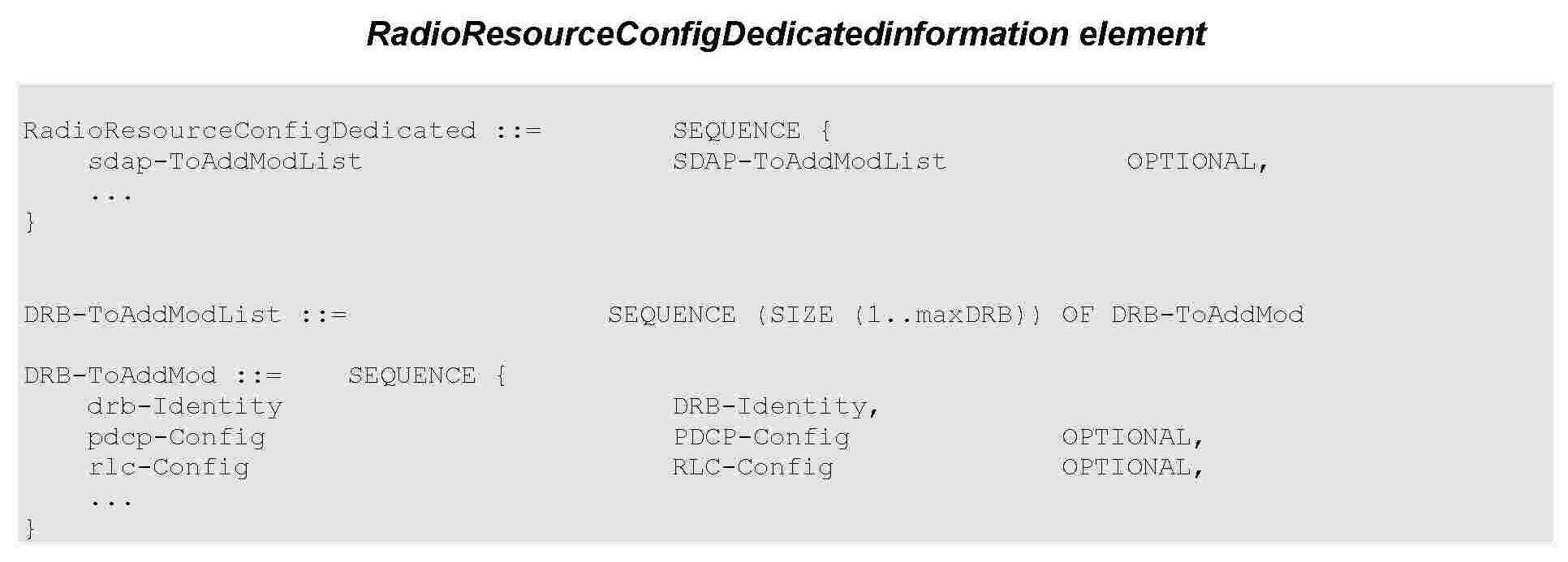

도 2k에서의 수신 PDCP 장치의 수신 패킷 처리 동작에서 사용되는 윈도우 상태 변수들은 다음과 같으며 윈도우 상태 변수들은 COUNT 값을 유지한다. The window state variables used in the receive packet processing operation of the receiving PDCP apparatus in FIG. 2K are as follows, and the window state variables retain the COUNT value.
- HFN : 윈도우 상태 변수의 HFN(Hyper Frame Number) 부분을 나타낸다. - HFN: Indicates the HFN (Hyper Frame Number) part of the window state variable.
- SN : 윈도우 상태 변수의 일련번호(SN, Sequence Number) 부분을 나타낸다.- SN: Represents the part of the window status variable (SN, Sequence Number).
- RCVD_SN : 수신한 PDCP PDU의 헤더에 포함되어 있는 PDCP 일련번호- RCVD_SN: The PDCP serial number contained in the header of the received PDCP PDU
- RCVD_HFN : 수신 PDCP 계층 장치가 계산한 수신한 PDCP PDU의 HFN 값- RCVD_HFN: HFN value of the received PDCP PDU calculated by the receiving PDCP layer apparatus
- RCVD_COUNT : 수신한 PDCP PDU의 COUNT 값 = [RCVD_HFN, RCVD_SN].- RCVD_COUNT: COUNT value of received PDCP PDU = [RCVD_HFN, RCVD_SN].
- RX_NEXT : 수신할 것이라고 예상되는 다음 PDCP SDU의 COUNT 값을 나타낸다. 초기값은 0이다. - RX_NEXT: Indicates the COUNT value of the next PDCP SDU expected to be received. The initial value is 0.
- RX_DELIV : 상위 계층으로 전달된 마지막 PDCP SDU의 COUNT 값을 나타낸다. 초기값은 2^32 -1이다. - RX_DELIV: indicates the COUNT value of the last PDCP SDU transmitted to the upper layer. The initial value is 2 ^ 32 -1.
- RX_REORD : t-Reordering 타이머를 트리거링했던 PDCP PDU에 해당하는 COUNT 값의 다음 COUNT 값을 나타낸다. - RX_REORD: indicates the next COUNT value of the COUNT value corresponding to the PDCP PDU that triggered the t-Reordering timer.
- t-Reordering : 상위 계층(RRC 계층, RRC 메시지로 설정, 도 1e의 1e-10, 1e-40. 1e-75)에서 설정된 타이머 값 혹은 구간을 사용. 상기 타이머는 유실된 PDCP PDU를 탐지하기 위해서 사용되고, 오로지 한번에 하나의 타이머만 구동된다. - t-Reordering: Use the timer value or interval set in the upper layer (RRC layer, RRC message, 1e-10, 1e-40.1e-75 in Fig. The timer is used to detect lost PDCP PDUs, and only one timer is driven at a time.
In this section, following definitions are used:In this section, the following definitions are used:
- HFN(State Variable): the HFN part (i.e. the number of most significant bits equal to HFN length) of the State Variable.- HFN (State Variable): the HFN part (i.e., the number of most significant bits equal to HFN length) of the State Variable.
- SN(State Variable): the SN part (i.e. the number of least significant bits equal to PDCP SN length) of the State Variable.- SN (State Variable): the SN part (i.e., the number of least significant bits equal to the PDCP SN length) of the State Variable.
- RCVD_SN: the PDCP SN of the received PDCP Data PDU, included in the PDU header.- RCVD_SN: the PDCP SN of the received PDCP Data PDU, included in the PDU header.
- RCVD_HFN: the HFN of the received PDCP Data PDU, calculated by the receiving PDCP entity.- RCVD_HFN: the HFN of the received PDCP Data PDU, calculated by the receiving PDCP entity.
- RCVD_COUNT: the COUNT of the received PDCP Data PDU = [RCVD_HFN, RCVD_SN].- RCVD_COUNT: the COUNT of the received PDCP Data PDU = [RCVD_HFN, RCVD_SN].
- RX_NEXT: This state variable indicates the COUNT value of the next PDCP SDU expected to be received. The initial value is 0.- RX_NEXT: This state variable indicates the COUNT value of the next PDCP SDU expected to be received. The initial value is 0.
- RX_DELIV: This state variable indicates the COUNT value of the last PDCP SDU delivered to the upper layers. The initial value is 232 - 1.- RX_DELIV: This state variable indicates the COUNT value of the last PDCP SDU delivered to the upper layers. The initial value is 2 32 - 1.
- RX_REORD: This state variable indicates the COUNT value following the COUNT value associated with the PDCP Data PDU which triggered t-Reordering.- RX_REORD: This state variable indicates the COUNT value associated with the PDCP PDU which triggered the t-Reordering .
- t-Reordering: The duration of the timer is configured by upper layers . This timer is used to detect loss of PDCP Data PDUs If t-Reordering is running, t-Reordering shall not be started additionally, i.e. only one t-Reordering per receiving PDCP entity is running at a given time.- t-Reordering: The duration of the timer is configured by the upper layers. This timer is used to detect loss of PDCP Data PDUs If t-Reordering is running, t-Reordering shall not be started additionally, ie only one t-Reordering per receiving PDCP entity is running at a given time.
본 발명에서 제안하는 PDCP 계층의 수신 동작의 제 5 실시 예는 다음과 같다. A fifth embodiment of the reception operation of the PDCP layer proposed in the present invention is as follows.
하위 계층으로부터 PDCP PDU를 수신하였을 때 동작Operation when PDCP PDU is received from the lower layer
(Actions when a PDCP Data PDU is received from lower layers)(Actions when a PDCP Data PDU is received from lower layers)
하위 계층으로부터 PDCP PDU를 수신하였을 때 수신 PDCP 계층 장치는 수신한 PDCP PDU의 COUNT 값을 다음과 같이 결정한다. When receiving a PDCP PDU from a lower layer, the receiving PDCP layer apparatus determines a COUNT value of the received PDCP PDU as follows.
- 만약 수신한 RCVD_SN이 RCVD_SN <= SN(RX_DELIV) - Window_Size 이라면 - If the received RCVD_SN is RCVD_SN <= SN (RX_DELIV) - Window_Size
■ RCVD_HFN = HFN(RX_DELIV) + 1 로 업데이트 한다. ■ RCVD_HFN = HFN (RX_DELIV) + 1.
- 그렇지 않고 만약 RCVD_SN이 RCVD_SN > SN(RX_DELIV) + Window_Size이라면 - Otherwise, if RCVD_SN is RCVD_SN> SN (RX_DELIV) + Window_Size
■ RCVD_HFN = HFN(RX_DELIV) - 1로 업데이트 한다. ■ RCVD_HFN = HFN (RX_DELIV) - 1.
- 상기의 경우가 아니라면 - If this is not the case
■ RCVD_HFN = HFN(RX_DELIV) 로 업데이트 한다. ■ RCVD_HFN = HFN (RX_DELIV).
- RCVD_COUNT 은 RCVD_COUNT = [RCVD_HFN, RCVD_SN] 와 같이 결정된다. - RCVD_COUNT is determined as RCVD_COUNT = [RCVD_HFN, RCVD_SN].
At reception of a PDCP Data PDU from lower layers, the receiving PDCP entity shall determine the COUNT value of the received PDCP Data PDU, i.e. RCVD_COUNT, as follows:At reception of a PDCP Data PDU from lower layers, the receiving PDCP entity will determine the COCP value of the received PDCP Data PDU, i.e. RCVD_COUNT, as follows:
- if RCVD_SN <= SN(RX_DELIV) - Window_Size:- if RCVD_SN <= SN (RX_DELIV) - Window_Size:
- RCVD_HFN = HFN(RX_DELIV) + 1; - RCVD_HFN = HFN (RX_DELIV) + 1;
- else if RCVD_SN > SN(RX_DELIV) + Window_Size:- else if RCVD_SN > SN (RX_DELIV) + Window_Size:
- RCVD_HFN = HFN(RX_DELIV) - 1; - RCVD_HFN = HFN (RX_DELIV) - 1;
- else:- else:
- RCVD_HFN = HFN(RX_DELIV);- RCVD_HFN = HFN (RX_DELIV);
- RCVD_COUNT = [RCVD_HFN, RCVD_SN].- RCVD_COUNT = [RCVD_HFN, RCVD_SN].
수신한 PDCP PDU의 COUNT 값을 결정하고 나면 수신 PDCP 계층 장치는 다음과 같이 윈도우 상태 변수들을 업데이트하고 PDCP PDU를 처리한다. After determining the COUNT value of the received PDCP PDU, the receiving PDCP layer device updates the window status variables and processes the PDCP PDU as follows.
- 만약 RCVD_COUNT <= RX_DELIV 이거나 혹은 RCVD_COUNT의 값을 갖는 PDCP PDU가 이전에 수신된 적이 있다면 - If RCVD_COUNT <= RX_DELIV or a PDCP PDU with a value of RCVD_COUNT has been received previously
■ 상기 RCVD_COUNT 값을 사용하여 상기 PDCP PDU에 대해서 복호화를 수행하고, 무결성 검증을 수행한다. ■ Performs decryption on the PDCP PDU using the RCVD_COUNT value, and performs integrity verification.
◆ 만약 무결성 검증에 실패했다면 ◆ If integrity verification fails
● 상위 계층의 무결성 검증 실패를 지시한다. ● Indicates failure of integrity verification of upper layer.
◆ 상기 PDCP PDU를 폐기한다. ◆ And discards the PDCP PDU.
- 그 외의 경우에 대해서는 다음의 동작을 수행한다. - In the other cases, the following operation is performed.
■ 상기 RCVD_COUNT 값을 사용하여 상기 PDCP PDU에 대해서 복호화를 수행하고, 무결성 검증을 수행한다. ■ Performs decryption on the PDCP PDU using the RCVD_COUNT value, and performs integrity verification.
◆ 만약 무결성 검증에 실패했다면 ◆ If integrity verification fails
● 상위 계층의 무결성 검증 실패를 지시한다. ● Indicates failure of integrity verification of upper layer.
● 상기 PDCP PDU를 폐기한다. Discard the PDCP PDU.
After determining the COUNT value of the received PDCP Data PDU = RCVD_COUNT, the receiving PDCP entity shall:After determining the COCP value of the received PDCP Data PDU = RCVD_COUNT, the receiving PDCP entity shall:
- if RCVD_COUNT <= RX_DELIV; or- if RCVD_COUNT <= RX_DELIV; or
- if the PDCP Data PDU with COUNT = RCVD_COUNT has been received before:- if PDCP Data PDU with COUNT = RCVD_COUNT has been received before:
- perform deciphering and integrity verification of the PDCP Data PDU using COUNT = RCVD_COUNT; - perform deciphering and integrity verification of the PDCP Data PDU using COUNT = RCVD_COUNT;
- if integrity verification fails:- if integrity verification fails:
- indicate the integrity verification failure to upper layer;- indicate integrity verification failure to upper layer;
- discard the PDCP Data PDU;- discard the PDCP Data PDU;
- else:- else:
- perform deciphering and integrity verification of the PDCP Data PDU using COUNT = RCVD_COUNT;- perform deciphering and integrity verification of the PDCP Data PDU using COUNT = RCVD_COUNT;
- if integrity verification fails:- if integrity verification fails:
- indicate the integrity verification failure to upper layer;- indicate integrity verification failure to upper layer;
- discard the PDCP Data PDU;- discard the PDCP Data PDU;
만약 상기에서 수신한 PDCP PDU가 버려지지 않았다면 수신 PDCP 계층 장치는 다음과 같이 동작한다.If the received PDCP PDU is not discarded, the receiving PDCP layer apparatus operates as follows.
- 상기에서 처리된 PDCP SDU를 수신 버퍼에 저장한다.- And stores the processed PDCP SDU in the reception buffer.
- 만약 RCVD_COUNT >= RX_NEXT라면 - If RCVD_COUNT> = RX_NEXT
■
RX_NEXT를 RCVD_COUNT + 1 로 업데이트한다. ■
Update RX_NEXT to
- 만약 RCVD_COUNT가 RX_DELIV + 1이고 비순서 전달이 설정되지 않았다면- If RCVD_COUNT is RX_DELIV + 1 and nonsequential delivery is not set
■ 헤더 압축 해제를 수행한 후에 COUNT 값 순서대로 상위 계층에 전달한다. ■ After decompressing the header, it transfers to the upper layer in order of COUNT value.
◆
COUNT = RX_DELIV + 1 부터 시작해서 연속적인 PDCP SDU들을 모두 상위 계층으로 전달한다. ◆
COUNT =
■ RX_DELIV 값을 상위 계층으로 전달한 마지막 PDCP SDU 의 COUNT 값으로 업데이트한다.■ The RX_DELIV value is updated to the COUNT value of the last PDCP SDU transmitted to the upper layer.
- 만약 RCVD_COUNT가 RX_DELIV + 1이고 비순서 전달이 설정되었고, RCVD_COUNT 값에 해당하는 PDCP SDU가 상위 계층으로 전달된 적이 없었다면- If RCVD_COUNT is set to RX_DELIV + 1 and non-ordered delivery is set and the PDCP SDU corresponding to the RCVD_COUNT value has not been delivered to the upper layer
■ 헤더 압축 해제를 수행한 후에 수신한 결과적인 PDCP SDU를 상위 계층에 전달한다. ■ And transmits the resultant PDCP SDU to the upper layer after performing header decompression.
■ RX_DELIV 값을 상위 계층으로 순서대로 전달한 마지막 PDCP SDU의 COUNT 값으로 업데이트한다. ■ The RX_DELIV value is updated to the COUNT value of the last PDCP SDU transmitted in order to the upper layer.
- 만약 비순서 전달이 설정되었고, RCVD_COUNT 값에 해당하는 PDCP SDU가 상위 계층으로 전달된 적이 없었다면- If the non-sequential delivery has been established and the PDCP SDU corresponding to the RCVD_COUNT value has not been delivered to the upper layer
■ 헤더 압축 해제를 수행한 후에 수신한 결과적인 PDCP SDU를 상위 계층에 전달한다. ■ And transmits the resultant PDCP SDU to the upper layer after performing header decompression.
- 만약 t-Reordering 타이머가 구동되고 있고, 비순서 전달이 설정되지 않았고, COUNT 값이 RX_REORD - 1 인 PDCP SDU가 상위 계층으로 전달되었다면 - If the t-reordering timer is running and no PDU SDU with COUNT value of RX_REORD - 1 is delivered to the upper layer
■ t-Reordering 타이머를 중지하고 리셋한다. ■ Stop and reset the t-reordering timer.
- 만약 t-Reordering 타이머가 구동되고 있지 않고, 비순서 전달이 설정되 않았고(상기 조건에서 중지된 경우도 포함하여) 적어도 하나의 PDCP SDU가 버퍼에 남아있다면 - If at least one PDCP SDU is left in the buffer if the t-reordering timer is not running, no non-ordered delivery is set (even if stopped in this condition)
■ RX_REORD 값을 RX_NEXT로 업데이트 한다. ■ Update the RX_REORD value to RX_NEXT.
■ t-Reordering 타이머를 시작한다. ■ Start the t-reordering timer.
- 만약 t-Reordering 타이머가 구동되고 있고, 비순서 전달이 설정되었다면 - If the t-reordering timer is running and non-ordered delivery is set
■ 만약 RX_REORD = RX_DELIV+1 이거나 RX_REORD <= RX_DELIV 인 경우, ■ If RX_REORD = RX_DELIV + 1 or RX_REORD <= RX_DELIV,
◆ t-Reordering 타이머를 중지하고 리셋한다. ◆ Stop and reset the t-reordering timer.
- 만약 t-Reordering 타이머가 구동되고 있지 않고, 비순서 전달이 설정되어 있다면- If the t-reordering timer is not running and non-ordered delivery is set
■
만약 RX_NEXT > RX_DELIV+1 이라면 ■
If RX_NEXT>
◆ RX_REORD를 RX_NEXT로 업데이트한다. ◆ Update RX_REORD to RX_NEXT.
◆ t-Reordering 타이머를 시작한다. ◆ Start the t-reordering timer.
If the received PDCP Data PDU with COUNT value = RCVD_COUNT is not discarded above, the receiving PDCP entity shall:If the received PDCP Data PDU with COUNT value = RCVD_COUNT is not discarded above, the receiving PDCP entity shall:
- store the resulting PDCP SDU in the reception buffer;- store the resulting PDCP SDU in the reception buffer;
- if RCVD_COUNT >= RX_NEXT:- if RCVD_COUNT> = RX_NEXT:
-
update RX_NEXT to RCVD_COUNT + 1;-
update RX_NEXT to
- if RCVD_COUNT = RX_DELIV + 1 and if outOfOrderDelivery is not configured:- if RCVD_COUNT = RX_DELIV + 1 and if outOfOrderDelivery is not configured:
- deliver to upper layers in ascending order of the associated COUNT value after performing header decompression;- deliver to upper layers in ascending order of associated COUNT value after performing header decompression;
-
all stored PDCP SDU(s) with consecutively associated COUNT value(s) starting from COUNT = RX_DELIV + 1;-
all stored PDCP SDU (s) with consecutively associated COUNT value (s) starting from COUNT =
- update RX_DELIV to the COUNT value of the last PDCP SDU delivered to upper layers;- update RX_DELIV to the COUNT value of the last PDCP SDU delivered to upper layers;
- if RCVD_COUNT = RX_DELIV + 1 and if outOfOrderDelivery is configured and the PDCP SDU with RCVD_COUNT has not been delivered to upper layers:- if RCVD_COUNT = RX_DELIV + 1 and if outOfOrderDelivery is configured and the PDCP SDU with RCVD_COUNT has not been delivered to upper layers:
- deliver the resulting PDCP SDU to upper layers after performing header decompression;- deliver the resulting PDCP SDU to upper layers after performing header decompression;
- update RX_DELIV to the COUNT value of the last in-sequence delivered PDCP SDU to upper layers;- update RX_DELIV to the COUNT value of the last in-sequence delivered PDCP SDU to upper layers;
- if outOfOrderDelivery is configured and the PDCP SDU with RCVD_COUNT has not been delivered to upper layers:- if outOfOrderDelivery is configured and the PDCP SDU with RCVD_COUNT has not been delivered to upper layers:
- deliver the resulting PDCP SDU to upper layers after performing header decompression;- deliver the resulting PDCP SDU to upper layers after performing header decompression;
- if t-Reordering is running and outOfOrderDelivery is not configured, and if the PDCP SDU with COUNT = RX_REORD - 1 has been delivered to upper layers:- if t-Reordering is running and outOfOrderDelivery is not configured, and if the PDCP SDU with COUNT = RX_REORD - 1 has been delivered to upper layers:
- stop and reset t-Reordering;- stop and reset t-Reordering ;
- if t-Reordering is not running and outOfOrderDelivery is not configured (includes the case when t-Reordering is stopped due to actions above), and if there is at least one stored PDCP SDU:- if t-Reordering is not running and outOfOrderDelivery is not configured (includes the case when t-Reordering is stopped due to actions above), and if there is at least one stored PDCP SDU:
- update RX_REORD to RX_NEXT;- update RX_REORD to RX_NEXT;
- start t-Reordering.- start t-Reordering .
if t-Reordering is running and outOfOrderDelivery is configured, if -Reordering is running and outOfOrderDelivery is configured,
- if RX_REORD = RX_DELIV+1; or
- if RX_REORD =
- if RX_REORD <= RX_DELIV ( or RX_REORD falls outside of the receiving window and RX_REORD is not equal to RX_DELIV + Window_Size) - if RX_REORD <= RX_DELIV (or RX_REORD falls outside of the receiving window and RX_REORD is not equal to RX_DELIV + Window_Size)
- stop and reset t-Reordering;- stop and reset t-Reordering ;
- if t-Reordering is not running and outOfOrderDelivery is configured (includes the case when t-Reordering is stopped due to actions above)- if t-Reordering is not running and outOfOrderDelivery is configured (includes the case when t-Reordering is stopped due to actions above)
- if RX_NEXT > RX_DELIV+1 (or RX_NEXT -1 > RX_DELIV):- if RX_NEXT> RX_DELIV + 1 (or RX_NEXT -1> RX_DELIV):
- update RX_REORD to RX_NEXT;- update RX_REORD to RX_NEXT;
- start t-Reordering.- start t-Reordering .
t-Reordering 타이머가 만료했을 때 수신 PDCP 계층 장치 동작The receiving PDCP layer device operation when the t-reordering timer expires.
(Actions when a t-Reordering expires)(Actions when a t-Reordering expires)
만약 비순서 전달이 설정되지 않았다면 t-Reordering 타이머가 만료하였을 때 수신 PDCP 계층 장치는 다음과 같이 동작한다. If non-ordered delivery is not set, the receiving PDCP layer device operates as follows when the t-reordering timer expires.
- 헤더 압축 해제를 수행한 후에 COUNT 값의 순서대로 상위 계층으로 전달한다. - After decompressing the header, the COUNT value is transmitted to the upper layer in order.
■ RX_REORD 값보다 작은 COUNT 값들을 가지는 모든 PDCP SDU들을 전달한다.■ All PDCP SDUs having COUNT values smaller than the RX_REORD value are transmitted.
■ RX_REORC 값부터 시작해서 연속적인 COUNT 값들을 가지는 모든 PDCP SDU들을 전달한다.■ All PDCP SDUs having consecutive COUNT values starting from the RX_REORC value are transmitted.
- RX_DELIV 값을 상위 계층으로 전달한 마지막 PDCP SDU의 COUNT값으로 업데이트한다. - The RX_DELIV value is updated to the COUNT value of the last PDCP SDU transmitted to the upper layer.
- 만약 적어도 하나의 PDCP SDU가 버퍼에 저장되어 있다면 - If at least one PDCP SDU is stored in the buffer
■ RX_REORD 값을 RX_NEXT 값으로 업데이트한다. ■ Update the RX_REORD value to the RX_NEXT value.
■ t-Reordering 타이머를 시작한다. ■ Start the t-reordering timer.
만약 비순서 전달이 설정되었다면 t-Reordering 타이머가 만료하였을 때 수신 PDCP 계층 장치는 다음과 같이 동작한다. If non-ordered delivery is set, the receiving PDCP layer device operates as follows when the t-reordering timer expires.
- RX_DELIV 를 RX_REORD 값 이상이면서 상위 계층으로 순서대로 전달된 마지막 COUNT 값으로 업데이트한다. - RX_DELIV is updated to the last COUNT value transmitted in order to the upper layer, which is equal to or greater than the RX_REORD value.
-
만약 RX_NEXT > RX_DELIV+1 이라면 -
If RX_NEXT>
■ RX_REORD 값을 RX_NEXT 값으로 업데이트한다. ■ Update the RX_REORD value to the RX_NEXT value.
■ t-Reordering 타이머를 시작한다. ■ Start the t-reordering timer.
If outOfOrderDelivery is not configured, when t-Reordering expires, the receiving PDCP entity shall:If outOfOrderDelivery is not configured, when t-Reordering expires, the receiving PDCP entity shall:
- deliver to upper layers in ascending order of the associated COUNT value after performing header decompression:- deliver to upper layers in ascending order of associated COUNT value after performing header decompression:
- all stored PDCP SDU(s) with associated COUNT value(s) < RX_REORD;- all stored PDCP SDU (s) with associated COUNT value (s) <RX_REORD;
- all stored PDCP SDU(s) with consecutively associated COUNT value(s) starting from RX_REORD;- all stored PDCP SDU (s) with consecutively associated COUNT value (s) starting from RX_REORD;
- update RX_DELIV to the COUNT value of the last PDCP SDU delivered to upper layers;- update RX_DELIV to the COUNT value of the last PDCP SDU delivered to upper layers;
- if there is at least one stored PDCP SDU:- if there is at least one stored PDCP SDU:
- update RX_REORD to RX_NEXT;- update RX_REORD to RX_NEXT;
- start t-Reordering.- start t-Reordering .
If outOfOrderDelivery is configured, when t-Reordering expires, the receiving PDCP entity shall:If outOfOrderDelivery is configured, when t-Reordering expires, the receiving PDCP entity shall:
- update RX_DELIV to the COUNT value > =RX_REORD of the last in-sequence delivered PDCP SDU to upper layers;- update RX_DELIV to the COUNT value> = RX_REORD of the last in-sequence delivered PDCP SDU to upper layers;
- If RX_NEXT > RX_DELIV+1 (or RX_NEXT -1 > RX_DELIV):- If RX_NEXT> RX_DELIV + 1 (or RX_NEXT -1> RX_DELIV):
- update RX_REORD to RX_NEXT- update RX_REORD to RX_NEXT
- start t-Reordering - start t-Reordering
본 발명에서 제안하는 PDCP 계층의 수신 동작의 제 6 실시 예는 다음과 같다. A sixth embodiment of the reception operation of the PDCP layer proposed in the present invention is as follows.
하위 계층으로부터 PDCP PDU를 수신하였을 때 동작Operation when PDCP PDU is received from the lower layer
(Actions when a PDCP Data PDU is received from lower layers)(Actions when a PDCP Data PDU is received from lower layers)
하위 계층으로부터 PDCP PDU를 수신하였을 때 수신 PDCP 계층 장치는 수신한 PDCP PDU의 COUNT 값을 다음과 같이 결정한다. When receiving a PDCP PDU from a lower layer, the receiving PDCP layer apparatus determines a COUNT value of the received PDCP PDU as follows.
- 만약 수신한 RCVD_SN이 RCVD_SN <= SN(RX_DELIV) - Window_Size 이라면 - If the received RCVD_SN is RCVD_SN <= SN (RX_DELIV) - Window_Size
■ RCVD_HFN = HFN(RX_DELIV) + 1 로 업데이트 한다. ■ RCVD_HFN = HFN (RX_DELIV) + 1.
- 그렇지 않고 만약 RCVD_SN이 RCVD_SN > SN(RX_DELIV) + Window_Size이라면 - Otherwise, if RCVD_SN is RCVD_SN> SN (RX_DELIV) + Window_Size
■ RCVD_HFN = HFN(RX_DELIV) - 1로 업데이트 한다. ■ RCVD_HFN = HFN (RX_DELIV) - 1.
- 상기의 경우가 아니라면 - If this is not the case
■ RCVD_HFN = HFN(RX_DELIV) 로 업데이트 한다. ■ RCVD_HFN = HFN (RX_DELIV).
- RCVD_COUNT 은 RCVD_COUNT = [RCVD_HFN, RCVD_SN] 와 같이 결정된다. - RCVD_COUNT is determined as RCVD_COUNT = [RCVD_HFN, RCVD_SN].
At reception of a PDCP Data PDU from lower layers, the receiving PDCP entity shall determine the COUNT value of the received PDCP Data PDU, i.e. RCVD_COUNT, as follows:At reception of a PDCP Data PDU from lower layers, the receiving PDCP entity will determine the COCP value of the received PDCP Data PDU, i.e. RCVD_COUNT, as follows:
- if RCVD_SN <= SN(RX_DELIV) - Window_Size:- if RCVD_SN <= SN (RX_DELIV) - Window_Size:
- RCVD_HFN = HFN(RX_DELIV) + 1;- RCVD_HFN = HFN (RX_DELIV) + 1;
- else if RCVD_SN > SN(RX_DELIV) + Window_Size:- else if RCVD_SN > SN (RX_DELIV) + Window_Size:
- RCVD_HFN = HFN(RX_DELIV) - 1;- RCVD_HFN = HFN (RX_DELIV) - 1;
- else:- else:
- RCVD_HFN = HFN(RX_DELIV);- RCVD_HFN = HFN (RX_DELIV);
- RCVD_COUNT = [RCVD_HFN, RCVD_SN].- RCVD_COUNT = [RCVD_HFN, RCVD_SN].
수신한 PDCP PDU의 COUNT 값을 결정하고 나면 수신 PDCP 계층 장치는 다음과 같이 윈도우 상태 변수들을 업데이트하고 PDCP PDU를 처리한다. After determining the COUNT value of the received PDCP PDU, the receiving PDCP layer device updates the window status variables and processes the PDCP PDU as follows.
- 만약 RCVD_COUNT <= RX_DELIV 이거나 혹은 RCVD_COUNT의 값을 갖는 PDCP PDU가 이전에 수신된 적이 있다면 - If RCVD_COUNT <= RX_DELIV or a PDCP PDU with a value of RCVD_COUNT has been received previously
■ 상기 RCVD_COUNT 값을 사용하여 상기 PDCP PDU에 대해서 복호화를 수행하고, 무결성 검증을 수행한다. ■ Performs decryption on the PDCP PDU using the RCVD_COUNT value, and performs integrity verification.
◆ 만약 무결성 검증에 실패했다면 ◆ If integrity verification fails
● 상위 계층의 무결성 검증 실패를 지시한다. ● Indicates failure of integrity verification of upper layer.
◆ 상기 PDCP PDU를 폐기한다. ◆ And discards the PDCP PDU.
- 그 외의 경우에 대해서는 다음의 동작을 수행한다. - In the other cases, the following operation is performed.
■ 상기 RCVD_COUNT 값을 사용하여 상기 PDCP PDU에 대해서 복호화를 수행하고, 무결성 검증을 수행한다. ■ Performs decryption on the PDCP PDU using the RCVD_COUNT value, and performs integrity verification.
◆ 만약 무결성 검증에 실패했다면 ◆ If integrity verification fails
● 상위 계층의 무결성 검증 실패를 지시한다. ● Indicates failure of integrity verification of upper layer.
● 상기 PDCP PDU를 폐기한다. Discard the PDCP PDU.
After determining the COUNT value of the received PDCP Data PDU = RCVD_COUNT, the receiving PDCP entity shall:After determining the COCP value of the received PDCP Data PDU = RCVD_COUNT, the receiving PDCP entity shall:
- if RCVD_COUNT <= RX_DELIV; or- if RCVD_COUNT <= RX_DELIV; or
- if the PDCP Data PDU with COUNT = RCVD_COUNT has been received before:- if PDCP Data PDU with COUNT = RCVD_COUNT has been received before:
- perform deciphering and integrity verification of the PDCP Data PDU using COUNT = RCVD_COUNT;- perform deciphering and integrity verification of the PDCP Data PDU using COUNT = RCVD_COUNT;
- if integrity verification fails:- if integrity verification fails:
- indicate the integrity verification failure to upper layer;- indicate integrity verification failure to upper layer;
- discard the PDCP Data PDU;- discard the PDCP Data PDU;
- else:- else:
- perform deciphering and integrity verification of the PDCP Data PDU using COUNT = RCVD_COUNT;- perform deciphering and integrity verification of the PDCP Data PDU using COUNT = RCVD_COUNT;
- if integrity verification fails:- if integrity verification fails:
- indicate the integrity verification failure to upper layer;- indicate integrity verification failure to upper layer;
- discard the PDCP Data PDU;- discard the PDCP Data PDU;
만약 상기에서 수신한 PDCP PDU가 버려지지 않았다면 수신 PDCP 계층 장치는 다음과 같이 동작한다.If the received PDCP PDU is not discarded, the receiving PDCP layer apparatus operates as follows.
- 상기에서 처리된 PDCP SDU를 수신 버퍼에 저장한다.- And stores the processed PDCP SDU in the reception buffer.
- 만약 RCVD_COUNT >= RX_NEXT라면 - If RCVD_COUNT> = RX_NEXT
■
RX_NEXT를 RCVD_COUNT + 1 로 업데이트한다. ■
Update RX_NEXT to
- 만약 RCVD_COUNT가 RX_DELIV + 1이고 비순서 전달이 설정되지 않았다면- If RCVD_COUNT is RX_DELIV + 1 and nonsequential delivery is not set
■ 헤더 압축 해제를 수행한 후에 COUNT 값 순서대로 상위 계층에 전달한다. ■ After decompressing the header, it transfers to the upper layer in order of COUNT value.
◆
COUNT = RX_DELIV + 1 부터 시작해서 연속적인 PDCP SDU들을 모두 상위 계층으로 전달한다. ◆
COUNT =
■ RX_DELIV 값을 상위 계층으로 전달한 마지막 PDCP SDU 의 COUNT 값으로 업데이트한다.■ The RX_DELIV value is updated to the COUNT value of the last PDCP SDU transmitted to the upper layer.
- 만약 RCVD_COUNT가 RX_DELIV + 1이고 비순서 전달이 설정되었고, RCVD_COUNT 값에 해당하는 PDCP SDU가 상위 계층으로 전달된 적이 없었다면- If RCVD_COUNT is set to RX_DELIV + 1 and non-ordered delivery is set and the PDCP SDU corresponding to the RCVD_COUNT value has not been delivered to the upper layer
■ 헤더 압축 해제를 수행한 후에 수신한 결과적인 PDCP SDU를 상위 계층에 전달한다. ■ And transmits the resultant PDCP SDU to the upper layer after performing header decompression.
■ RX_DELIV 값을 상위 계층으로 순서대로 전달한 마지막 PDCP SDU의 COUNT 값으로 업데이트한다. ■ The RX_DELIV value is updated to the COUNT value of the last PDCP SDU transmitted in order to the upper layer.
- 만약 비순서 전달이 설정되었고, RCVD_COUNT 값에 해당하는 PDCP SDU가 상위 계층으로 전달된 적이 없었다면- If the non-sequential delivery has been established and the PDCP SDU corresponding to the RCVD_COUNT value has not been delivered to the upper layer
■ 헤더 압축 해제를 수행한 후에 수신한 결과적인 PDCP SDU를 상위 계층에 전달한다. ■ And transmits the resultant PDCP SDU to the upper layer after performing header decompression.
- 만약 t-Reordering 타이머가 구동되었다면- If the t-reordering timer is running
■ 만약 RX_REORD = RX_DELIV+1 이거나 RX_REORD <= RX_DELIV 인 경우, ■ If RX_REORD = RX_DELIV + 1 or RX_REORD <= RX_DELIV,
◆ t-Reordering 타이머를 중지하고 리셋한다. ◆ Stop and reset the t-reordering timer.
- 만약 t-Reordering 타이머가 구동되고 있지 않다면- If the t-reordering timer is not running
■
만약 RX_NEXT > RX_DELIV+1 이라면 ■
If RX_NEXT>
◆ RX_REORD를 RX_NEXT로 업데이트한다. ◆ Update RX_REORD to RX_NEXT.
◆ t-Reordering 타이머를 시작한다. ◆ Start the t-reordering timer.
If the received PDCP Data PDU with COUNT value = RCVD_COUNT is not discarded above, the receiving PDCP entity shall:If the received PDCP Data PDU with COUNT value = RCVD_COUNT is not discarded above, the receiving PDCP entity shall:
- store the resulting PDCP SDU in the reception buffer;- store the resulting PDCP SDU in the reception buffer;
- if RCVD_COUNT >= RX_NEXT:- if RCVD_COUNT> = RX_NEXT:
-
update RX_NEXT to RCVD_COUNT + 1;-
update RX_NEXT to
- if RCVD_COUNT = RX_DELIV + 1 and if outOfOrderDelivery is not configured:- if RCVD_COUNT = RX_DELIV + 1 and if outOfOrderDelivery is not configured:
- deliver to upper layers in ascending order of the associated COUNT value after performing header decompression;- deliver to upper layers in ascending order of associated COUNT value after performing header decompression;
-
all stored PDCP SDU(s) with consecutively associated COUNT value(s) starting from COUNT = RX_DELIV + 1;-
all stored PDCP SDU (s) with consecutively associated COUNT value (s) starting from COUNT =
- update RX_DELIV to the COUNT value of the last PDCP SDU delivered to upper layers;- update RX_DELIV to the COUNT value of the last PDCP SDU delivered to upper layers;
- if RCVD_COUNT = RX_DELIV + 1 and if outOfOrderDelivery is configured and the PDCP SDU with RCVD_COUNT has not been delivered to upper layers:- if RCVD_COUNT = RX_DELIV + 1 and if outOfOrderDelivery is configured and the PDCP SDU with RCVD_COUNT has not been delivered to upper layers:
- deliver the resulting PDCP SDU to upper layers after performing header decompression;- deliver the resulting PDCP SDU to upper layers after performing header decompression;
- update RX_DELIV to the COUNT value of the last in-sequence delivered PDCP SDU to upper layers;- update RX_DELIV to the COUNT value of the last in-sequence delivered PDCP SDU to upper layers;
- if outOfOrderDelivery is configured and the PDCP SDU with RCVD_COUNT has not been delivered to upper layers:- if outOfOrderDelivery is configured and the PDCP SDU with RCVD_COUNT has not been delivered to upper layers:
- deliver the resulting PDCP SDU to upper layers after performing header decompression;- deliver the resulting PDCP SDU to upper layers after performing header decompression;
- if t-Reordering is running, - if t-Reordering is running,
- if RX_REORD = RX_DELIV+1 ; or
- if RX_REORD =
- if RX_REORD <= RX_DELIV ( or RX_REORD falls outside of the receiving window and RX_REORD is not equal to RX_DELIV + Window_Size+1) - if RX_REORD <= RX_DELIV (or RX_REORD falls outside of the receiving window and RX_REORD is not equal to RX_DELIV + Window_Size + 1)
- stop and reset t-Reordering;- stop and reset t-Reordering ;
- if t-Reordering is not running (includes the case when t-Reordering is stopped due to actions above)- if t-Reordering is not running (includes the case when t-Reordering is stopped due to actions above)
- if RX_NEXT > RX_DELIV+1 (or RX_NEXT -1 > RX_DELIV):- if RX_NEXT> RX_DELIV + 1 (or RX_NEXT -1> RX_DELIV):
- update RX_REORD to RX_NEXT;- update RX_REORD to RX_NEXT;
- start t-Reordering.- start t-Reordering .
t-Reordering 타이머가 만료했을 때 수신 PDCP 계층 장치 동작The receiving PDCP layer device operation when the t-reordering timer expires.
(Actions when a t-Reordering expires)(Actions when a t-Reordering expires)
만약 비순서 전달이 설정되지 않았다면 t-Reordering 타이머가 만료하였을 때 수신 PDCP 계층 장치는 다음과 같이 동작한다. If non-ordered delivery is not set, the receiving PDCP layer device operates as follows when the t-reordering timer expires.
- 헤더 압축 해제를 수행한 후에 COUNT 값의 순서대로 상위 계층으로 전달한다. - After decompressing the header, the COUNT value is transmitted to the upper layer in order.
■ RX_REORD 값보다 작은 COUNT 값들을 가지는 모든 PDCP SDU들을 전달한다.■ All PDCP SDUs having COUNT values smaller than the RX_REORD value are transmitted.
■ RX_REORC 값부터 시작해서 연속적인 COUNT 값들을 가지는 모든 PDCP SDU들을 전달한다.■ All PDCP SDUs having consecutive COUNT values starting from the RX_REORC value are transmitted.
- RX_DELIV 값을 상위 계층으로 전달한 마지막 PDCP SDU의 COUNT값으로 업데이트한다. - The RX_DELIV value is updated to the COUNT value of the last PDCP SDU transmitted to the upper layer.
- 만약 적어도 하나의 PDCP SDU가 버퍼에 저장되어 있다면 - If at least one PDCP SDU is stored in the buffer
■ RX_REORD 값을 RX_NEXT 값으로 업데이트한다. ■ Update the RX_REORD value to the RX_NEXT value.
■ t-Reordering 타이머를 시작한다. ■ Start the t-reordering timer.
만약 비순서 전달이 설정되었다면 t-Reordering 타이머가 만료하였을 때 수신 PDCP 계층 장치는 다음과 같이 동작한다. If non-ordered delivery is set, the receiving PDCP layer device operates as follows when the t-reordering timer expires.
- RX_DELIV 를 RX_REORD 값 이상이면서 상위 계층으로 순서대로 전달된 마지막 COUNT 값으로 업데이트한다. - RX_DELIV is updated to the last COUNT value transmitted in order to the upper layer, which is equal to or greater than the RX_REORD value.
-
만약 RX_NEXT > RX_DELIV+1 이라면 -
If RX_NEXT>
■ RX_REORD 값을 RX_NEXT 값으로 업데이트한다. ■ Update the RX_REORD value to the RX_NEXT value.
■ t-Reordering 타이머를 시작한다. ■ Start the t-reordering timer.
If outOfOrderDelivery is not configured, when t-Reordering expires, the receiving PDCP entity shall:If outOfOrderDelivery is not configured, when t-Reordering expires, the receiving PDCP entity shall:
- deliver to upper layers in ascending order of the associated COUNT value after performing header decompression:- deliver to upper layers in ascending order of associated COUNT value after performing header decompression:
- all stored PDCP SDU(s) with associated COUNT value(s) < RX_REORD;- all stored PDCP SDU (s) with associated COUNT value (s) <RX_REORD;
- all stored PDCP SDU(s) with consecutively associated COUNT value(s) starting from RX_REORD;- all stored PDCP SDU (s) with consecutively associated COUNT value (s) starting from RX_REORD;
- update RX_DELIV to the COUNT value of the last PDCP SDU delivered to upper layers;- update RX_DELIV to the COUNT value of the last PDCP SDU delivered to upper layers;
- if there is at least one stored PDCP SDU:- if there is at least one stored PDCP SDU:
- update RX_REORD to RX_NEXT;- update RX_REORD to RX_NEXT;
- start t-Reordering.- start t-Reordering .
If outOfOrderDelivery is configured, when t-Reordering expires, the receiving PDCP entity shall:If outOfOrderDelivery is configured, when t-Reordering expires, the receiving PDCP entity shall:
- update RX_DELIV to the COUNT value > =RX_REORD of the last in-sequence delivered PDCP SDU to upper layers;- update RX_DELIV to the COUNT value> = RX_REORD of the last in-sequence delivered PDCP SDU to upper layers;
- If RX_NEXT > RX_DELIV+1 (or RX_NEXT -1 > RX_DELIV):- If RX_NEXT> RX_DELIV + 1 (or RX_NEXT -1> RX_DELIV):
- update RX_REORD to RX_NEXT- update RX_REORD to RX_NEXT
start t-Reordering start t-Reordering
상기 본 발명의 실시 예들에서In the embodiments of the present invention
- update RX_DELIV to the COUNT value of the last in-sequence delivered PDCP SDU to upper layers;- update RX_DELIV to the COUNT value of the last in-sequence delivered PDCP SDU to upper layers;
라는 상기 문구는 다음과 같이 동일한 의미를 갖는 또 다른 문구로 대체될 수 있다. Can be replaced with another phrase having the same meaning as follows.
- update RX_DELIV to x-1, where x is the COUNT value of the first PDCP SDU which has not been delivered to upper layers- update RX_DELIV to x-1, where x is the COUNT value of the first PDCP SDU.
즉, 상기 두 문구는 동일한 의미를 갖는다. That is, the two phrases have the same meaning.
또한 상기 본 발명의 실시 예들에서 PDCP 계층 장치가 비순서 전달을 하도록 설정된 경우, 즉, RRC 메시지로 비순서전달(outofsequenceDelivery)이 설정된 경우, 헤더 압축 알고리즘(예를 들면 RoHC)은 적용될 수 없으며(헤더 압축 알고리즘은 순서대로 전달된 패킷에 대해서만 수신단 PDCP 계층 장치가 정상적으로 압축 해제 알고리즘을 성공적으로 수행할 수 있기 때문이다), 따라서 수신 PDCP 계층 장치에서 헤더 압축을 해제하는 절차(header decompression)를 생략할 수 있다.Also, in the embodiments of the present invention, when the PDCP layer device is set to perform non-sequential delivery, that is, when out-of-sequence delivery is set as an RRC message, a header compression algorithm (for example, RoHC) Since the compression algorithm can normally successfully perform the decompression algorithm only for the packets that are delivered in sequence, the receiving PDCP layer device can successfully perform the decompression algorithm), and thus the header decompression process of the receiving PDCP layer device can be omitted have.
<제3실시예>≪ Third Embodiment >
이하 첨부된 도면을 참조하여 본 발명의 동작 원리를 상세히 설명한다. 하기에서 본 발명을 설명하기에 있어 관련된 공지 기능 또는 구성에 대한 구체적인 설명이 본 발명의 요지를 불필요하게 흐릴 수 있다고 판단되는 경우에는 그 상세한 설명을 생략할 것이다. 그리고 후술되는 용어들은 본 발명에서의 기능을 고려하여 정의된 용어들로서 이는 사용자, 운용자의 의도 또는 관례 등에 따라 달라질 수 있다. 그러므로 그 정의는 본 명세서 전반에 걸친 내용을 토대로 내려져야 할 것이다.Hereinafter, the operation principle of the present invention will be described in detail with reference to the accompanying drawings. DETAILED DESCRIPTION OF THE PREFERRED EMBODIMENTS Hereinafter, a detailed description of known functions and configurations incorporated herein will be omitted when it may make the subject matter of the present invention rather unclear. The following terms are defined in consideration of the functions of the present invention, and these may be changed according to the intention of the user, the operator, or the like. Therefore, the definition should be based on the contents throughout this specification.
이하 설명에서 사용되는 접속 노드(node)를 식별하기 위한 용어, 망 객체(network entity)들을 지칭하는 용어, 메시지들을 지칭하는 용어, 망 객체들 간 인터페이스를 지칭하는 용어, 다양한 식별 정보들을 지칭하는 용어 등은 설명의 편의를 위해 예시된 것이다. 따라서, 본 발명이 후술되는 용어들에 한정되는 것은 아니며, 동등한 기술적 의미를 가지는 대상을 지칭하는 다른 용어가 사용될 수 있다.A term used for identifying a connection node used in the following description, a term referring to network entities, a term referring to messages, a term indicating an interface between network objects, a term indicating various identification information Etc. are illustrated for convenience of explanation. Therefore, the present invention is not limited to the following terms, and other terms referring to objects having equivalent technical meanings can be used.
이하 설명의 편의를 위하여, 본 발명은 현재 존재하는 통신표준가운데 가장 최신의 표준인 3GPP LTE (The 3rd Generation Partnership Project Long Term Evolution) 규격에서 정의하고 있는 용어 및 명칭들을 사용한다. 하지만, 본 발명이 상기 용어 및 명칭들에 의해 한정되는 것은 아니며, 다른 규격에 따르는 시스템에도 동일하게 적용될 수 있다. 특히 본 발명은 3GPP NR (New Radio: 5세대 이동통신 표준)에 적용할 수 있다.For convenience of explanation, the present invention uses terms and names defined in the 3GPP LTE (Long Term Evolution) standard, which is the most recent standard among existing communication standards. However, the present invention is not limited by the above-mentioned terms and names, and can be equally applied to systems conforming to other standards. In particular, the present invention is applicable to 3GPP NR (New Radio: 5th generation mobile communication standard).
도 3a은 본 발명의 설명을 위해 참고로 하는 LTE 시스템의 구조를 도시하는 도면이다.FIG. 3A is a diagram showing a structure of a LTE system as a reference for explaining the present invention.
상기 도 3a을 참고하면, 상기 무선 통신 시스템은 여러 개의 기지국들 (3a-05)(3a-10)(3a-15)(3a-20)과 MME (Mobility Management Entity)(3a-20) 및 S-GW (Serving-Gateway)(3a-30)로 구성된다. 사용자 단말(User Equipment, 이하 UE 또는 단말)(3a-35)은 기지국(3a-05)(3a-10)(3a-15)(3a-20) 및 S-GW(3a-30)을 통해 외부 네트워크에 접속한다.3A, the wireless communication system includes a plurality of
상기 기지국들(3a-05)(3a-10)(3a-15)(3a-20)은 셀룰러 망의 접속 노드로서 망에 접속하는 단말들에게 무선 접속을 제공한다. 즉, 상기 기지국(3a-05)(3a-10)(3a-15)(3a-20)은 사용자들의 트래픽을 서비스하기 위해 단말들의 버퍼 상태, 가용 전송 전력 상태, 채널 상태 등의 상태 정보를 취합해서 스케쥴링을 하여 상기 단말들과 코어 망(CN, Core network)간에 연결을 지원한다. 상기 MME(3a-25)는 단말에 대한 이동성 관리 기능은 물론 각종 제어 기능을 담당하는 장치로 다수의 기지국들과 연결되며, S-GW(3a-30)는 데이터 베어러를 제공하는 장치이다. 또한, 상기 MME(3a-25) 및 S-GW(3a-30)는 망에 접속하는 단말에 대한 인증(authentication), 베어러(bearer) 관리 등을 더 수행할 수 있으며 상기 기지국(3a-05)(3a-10)(3a-15)(3a-20)으로부터 도착한 패킷 또는 상기 기지국 (3a-05)(3a-10)(3a-15)(3a-20)으로 전달할 패킷을 처리한다.The
도 3b는 본 발명의 설명을 위해 참고로 하는 LTE 시스템의 무선 프로토콜 구조를 나타낸 도면이다. 향후 정의될 NR에서는 본 도면에서의 무선 프로토콜 구조와는 일부 상이할 수 있으나, 본 발명의 설명의 편의를 위해 설명하도록 한다.FIG. 3B is a diagram illustrating a wireless protocol structure of an LTE system for the purpose of explanation of the present invention. The NR to be defined in the future may be partially different from the radio protocol structure in this figure, but will be described for convenience of explanation of the present invention.
도 3b를 참조하면, LTE 시스템의 무선 프로토콜은 단말과 ENB에서 각각 PDCP(Packet Data Convergence Protocol)(3b-05)(3b-40), RLC(Radio Link Control)(3b-10)(3b-35), MAC (Medium Access Control)(3b-15)(3b-30)으로 이루어진다. PDCP(Packet Data Convergence Protocol) (3b-05)(3b-40)는 IP 헤더 압축/복원 등의 동작을 담당하고, 무선 링크 제어(Radio Link Control, 이하 RLC라고 한다) (3b-10)(3b-35)는 PDCP PDU(Packet Data Unit)를 적절한 크기로 재구성한다. MAC(3b-15)(3b-30)은 한 단말에 구성된 여러 RLC 계층 장치들과 연결되며, RLC PDU들을 MAC PDU에 다중화하고 MAC PDU로부터 RLC PDU들을 역다중화하는 동작을 수행한다. 물리 계층(3b-20)(3b-25)은 상위 계층 데이터를 채널 코딩 및 변조하고, OFDM 심벌로 만들어서 무선 채널로 전송하거나, 무선 채널을 통해 수신한 OFDM 심벌을 복조하고 채널 디코딩해서 상위 계층으로 전달하는 동작을 한다. 또한 물리 계층에서도 추가적인 오류 정정을 위해, HARQ (Hybrid ARQ) 를 사용하고 있으며, 수신단에서는 송신단에서 전송한 패킷의 수신여부를 1 비트로 전송한다. 이를 HARQ ACK/NACK 정보라 한다. 업링크 전송에 대한 다운링크 HARQ ACK/NACK 정보는 PHICH (Physical Hybrid-ARQ Indicator Channel) 물리 채널을 통해 전송되며 다운링크 전송에 대한 업링크 HARQ ACK/NACK 정보는 PUCCH (Physical Uplink Control Channel)이나 PUSCH (Physical Uplink Shared Channel) 물리 채널을 통해 전송될 수 있다.3B, the wireless protocol of the LTE system includes Packet Data Convergence Protocol (PDCP) (3b-05) 3b-40 and RLC (Radio Link Control) 3b-10 ), And a MAC (Medium Access Control) 3b-15 (3b-30). The Packet Data Convergence Protocol (PDCP) 3b-05 3b-40 is responsible for operations such as IP header compression / decompression and performs Radio Link Control (RLC) 3b-10 -35) reconfigures the PDCP PDU (Packet Data Unit) to an appropriate size. The MAC (3b-15) 3b-30 is connected to a plurality of RLC layer devices arranged in one terminal, multiplexes RLC PDUs into MAC PDUs, and demultiplexes RLC PDUs from MAC PDUs. The
한편 상기 PHY 계층은 하나 혹은 복수 개의 주파수/반송파로 이루어질 수 있으며, 하나의 기지국에서 복수 개의 주파수를 동시에 설정하여 사용하는 기술을 반송파 집적 기술 (carrier aggreagation, 이하 CA라 칭함)이라 한다. CA 기술이란 단말 (혹은 User Equipment, UE) 과 기지국 (E-UTRAN NodeB, eNB) 사이의 통신을 위해 하나의 반송파만 사용하던 것을, 주반송파와 하나 혹은 복수개의 부차반송파를 추가로 사용하여 부차반송파의 갯수만큼 전송량을 획기적으로 늘릴 수 있다. 한편, LTE에서는 주반송파를 사용하는 기지국 내의 셀을 PCell (Primary Cell)이라 하며, 부차반송파를 SCell (Secondary Cell)이라 칭한다. 상기의 CA기능을 두개의 기지국으로 확장한 기술을 이중 연결 기술 (dual connectivity, 이하 DC라 칭함)이라 한다. 상기 DC 기술에서는 단말이 주기지국 (Master E-UTRAN NodeB, 이하 MeNB라 칭함)과 보조기지국 (Secondary E-UTRAN NodeB, 이하 SeNB라 칭함)을 동시에 연결해서 사용하고 있으며, 주기지국 내에 속한 셀들을 주셀그룹 (Master Cell Group, 이하 MCG라 칭함)이라 하고, 보조기지국에 속한 셀들을 보조셀그룹 (Secondary Cell Group, 이하 SCG라 칭함)이라 한다. 상기 각 셀그룹별로 대표셀이 있으며, 주셀그룹의 대표 셀을 주셀(Primary Cell, 이하 PCell이라 칭함)이라 하고, 보조셀그룹의 대표 셀을 주보조셀 (Primary Secondary Cell, 이하 PSCell이라 칭함)이라 한다. 전술한 NR을 사용할 때, 상기 MCG를 LTE 기술을 사용하고 상기 SCG를 NR로 사용하여, LTE와 NR을 단말이 동시에 사용할 수 있다.Meanwhile, the PHY layer may be composed of one or a plurality of frequency / carriers, and a technique of simultaneously setting and using a plurality of frequencies in one base station is referred to as a carrier aggre- gation (CA). The CA technology is a technique in which only one carrier is used for communication between a UE (User Equipment, UE) and a base station (E-UTRAN NodeB, eNB), and the subcarrier is further used by using one or more sub- It is possible to dramatically increase the amount of transmission. In LTE, a cell in a base station using a main carrier is referred to as PCell (Primary Cell), and a secondary carrier is referred to as SCell (Secondary Cell). A technology in which the CA function is extended to two base stations is referred to as dual connectivity (hereinafter referred to as DC). In the DC technique, a UE concurrently connects a Master E-UTRAN NodeB (MeNB) and a Secondary E-UTRAN NodeB (SeNB) (MCG), and cells belonging to the auxiliary base station are referred to as a secondary cell group (SCG). The representative cell of the main cell group is referred to as a primary cell (hereinafter referred to as PCell), and the representative cell of the auxiliary cell group is referred to as a primary secondary cell (hereinafter referred to as PSCell) do. When using the above-mentioned NR, the MCG can use LTE technology and the SCG can be used as NR so that the UE can simultaneously use LTE and NR.
본 도면에 도시하지 않았지만, 단말과 기지국의 PDCP 계층의 상위에는 각각 RRC (Radio Resource Control, 이하 RRC라고 한다) 계층이 존재하며, 상기 RRC 계층은 무선 자원 제어를 위해 접속 및 측정 관련 설정 제어 메시지를 주고 받을 수 있다. 예를 들어, 상기 RRC 계층의 메시지를 사용하여 단말에게 측정을 지시할 수 있으며, 단말은 측정 결과를 상기 RRC계층의 메시지를 사용하여 기지국에게 보고할 수 있다.Although not shown in the figure, RRC (Radio Resource Control) layers exist in the upper part of the PDCP layer of the UE and the base station, respectively. The RRC layer transmits connection and measurement related control messages for radio resource control You can send and receive. For example, the RRC layer can instruct the UE to perform measurement using the RRC layer message, and the UE can report the measurement result to the RAS using the RRC layer message.
도 3c는 상기 Dual Connectivity의 개념을 설명하기 위한 도면이다.3C is a diagram for explaining the concept of the Dual Connectivity.
Dual connectivity (DC) 기술을 사용하면 단말은 두개의 기지국을 동시에 연결하여 사용할 수 있으며, 본 예시 도면에서는 단말 (3c-05)이 LTE 기술을 사용하는 매크로 기지국 (3c-00)과 NR 기술을 사용하는 스몰셀 기지국 (3c-10)를 동시에 연결하여 데이터를 송수신하는 경우를 도시하였다. 이를 EN-DC 라 칭한다 (E-UTRAN-NR Dual Connectivity) 매크로 기지국은 MeNB (Master E-UTRAN NodeB)로 칭하며, 스몰셀 기지국은 SgNB (Secondary 5G NodeB)로 칭한다. MeNB의 서비스 영역 내에 여러 개의 스몰 셀이 존재할 수 있으며, MeNB은 상기 SgNB들과 유선 backhaul 망 (3c-15)로 연결되어 있다. MeNB로부터 제공받는 서빙 셀의 집합을 MCG (Master Cell Group) (3c-20)라고 하며, MCG에서 반드시 하나의 서빙 셀은 connection establishment, connection re-establishment, handover 등 기존 셀이 수행해왔던 기능들을 모두 가지는 PCell (primary Cell) (3c-25) 이다. 또한 상기 PCell에서는 상향링크 제어채널은 PUCCH을 가진다. PCell 이외의 서빙 셀을 SCell (Secondary Cell) (3c-30)이라고 한다. 도 3c에서는 MeNB가 하나의 SCell을, SgNB가 3 개의 SCell들을 제공하는 시나리오를 도시하고 있다. SgNB가 제공하는 서빙 셀의 집합을 SCG (Secondary Cell Group) (3c-40)이라고 칭한다. MeNB은 상기 단말이 두 기지국으로부터 데이터를 송수신할 때, SgNB에서 제공하는 서빙 셀들을 추가, 변경, 제거하는 명령을 SgNB에 내린다. 이러한 명령을 내리기 위해서, MeNB는 단말에게 서빙 셀 및 주변 셀들을 측정하도록 설정 (Configuration)할 수 있다. 단말은 설정 정보에 따라, 측정한 결과를 MeNB에 보고해야 한다. SgNB이 단말에게 효율적으로 데이터를 송수신하기 위해서는 MCG의 PCell과 유사한 역할을 하는 서빙 셀이 필요하며, 본 발명에서는 이를 PSCell (Primary SCell)이라고 칭한다. PSCell은 SCG의 서빙 셀 중, 하나로 정해지며, 상향링크 제어채널인 PUCCH을 가지고 있는 것을 특징으로 한다. PUCCH는 단말이 HARQ ACK/NACK 정보, CSI (Channel Status Information) 정보, SR (Scheduling Request) 등을 기지국에 전달하는데 이용된다.In the illustrated example, the terminal 3c-05 uses the
도 3d는 단말이 동일 혹은 이종 RAT 의 복수 기지국과 동시 연결을 수행 시, 연결 실패를 판단하고 처리하는 방법 사용시 단말과 기지국 간의 메시지 흐름 예시 도면이다.FIG. 3D is an exemplary diagram of a message flow between a terminal and a base station when a method of determining and processing a connection failure when a terminal performs simultaneous connection with a plurality of base stations of the same or different RATs.
본 예시도면에서 설명의 편의를 위해 LTE와 NR 기지국에 접속하는 단말을 예시로 도시하였으나, 본 내용은 동종 기지국 (예를 들어 NR 기지국과 NR 기지국) 들 간의 복수 접속에도 공히 적용할 수 있다.Although the terminal connected to the LTE and the NR base station is illustrated as an example for convenience of explanation in the present exemplary drawing, the present invention can also be applied to a plurality of connections between homogeneous base stations (for example, an NR base station and an NR base station).
본 예시 도면에서 휴면 모드 (RRC_IDLE)에 있는 단말 (3d-01)은 보낼 데이터의 발생 등의 이유로 LTE 셀로 접속을 수행한다 (3d-11). 상기 휴면 모드에서는 단말의 전력 절약 등을 위해 네트워크와 연결이 되어 있지 않아 데이터를 전송할 수 없는 상태이며, 데이터 전송을 위해서는 연결 모드 (RRC_CONNECTED)로 천이가 필요하다. 단말이 LTE 셀 (3d-03)에 접속 절차를 성공하면, 단말은 연결 모드 (RRC_CONNECTED)로 상태가 변경이 되며, 상기 연결모드에 있는 단말은 제어 메시지를 위한 베어러 (Siganlling Radio Bearer, SRB)가 설정되며, 이후 시큐리티 활성화 및 데이터를 위한 베어러 (Data Radio Bearer, DRB) 설정 등을 통해 LTE 셀과 데이터 송수신이 가능하다. 상기 제어 메시지를 위한 베어러는 제어 메시지 종류에 따라 SRB1, SRB2로 나뉜다.In the drawing, the terminal 3d-01 in the sleep mode (RRC_IDLE) performs connection to the LTE cell for the reason such as generation of data to be transmitted (3d-11). In the sleep mode, data can not be transmitted because the mobile station is not connected to the network for power saving or the like. In order to transmit data, a transition to a connection mode (RRC_CONNECTED) is required. If the UE succeeds in the connection procedure to the
이후 기지국이 단말에게 NR셀을 SCG로 추가하기로 결정한 경우, 기지국은 단말에게 전술한 DC기능을 설정하기 위해 SCG 설정 정보를 전송한다 (3d-13). 상기 SCG 설정 정보에는 SCG로 추가하는 SCell들에 대한 추가 및 해지 정보가 포함될 수 있다. 또한, SCG가 생성한 제어 메시지를 SCG 기지국을 통해서 전송 가능하도록 SRB3를 추가로 설정하는 정보가 포함될 수 있다. 뿐만 아니라, 상기 SCG를 통해서 전송할 베어러에 대한 정보도 포함될 수 있다. 상기 설정 정보들은 RRC계층의 RRCConnectionReconfiguration 메시지를 사용해 전송될 수 있다. 이후, 단말은 상기 설정 정보를 수신하였음을 확인하는 메시지를 전송하며, 이는 RRCConnectionReconfigurationComplete 메시지를 사용해 전송될 수 있다 (3d-15). 이에 따라 단말은 MCG인 LTE 셀 (3d-03)과 SCG인 NR 셀 (3d-05)를 사용해 동시에 데이터를 송수신할 수 있으며, SRB3가 설정된 경우 SRB3를 통해 제어 메시지가 송수신될 수 있다 (3d-17) (3d-19). 뿐만 아니라, 안정성들을 이유로 상기 SRB1/2로 전송되는 패킷을 MCG와 SCG로 복제하여 전송할 수도 있다. 역시 마찬가지로 상기 SRB3로 전송되는 패킷을 SCG와 MCG로 복제하여 전송할 수도 있다. 이를 스플릿 (split) 베어러라 한다. 또한, MCG와 연결된 MCG CN으로부터 오는 데이터를 MCG와 SCG로 전송하는 베어러를 MCG 스플릿 베어러라 하며, SCG와 연결된 SCG CN으로부터 오는 데이터를 SCG와 MCG로 전송하는 베어러를 SCG 스플릿 베어러라 한다. 또한 상향링크 하향링크 공히 적용될 수 있다.If the base station determines to add the NR cell to the terminal by SCG, the base station transmits the SCG setup information to the terminal in order to set the DC function (3d-13). The SCG setting information may include addition and cancellation information for SCells to be added to the SCG. In addition, information for further setting the
상기와 같이 단말이 SRB 혹은 DRB로 데이터 송수신 시, 단말은 각 패킷에 대해 무결성 검사를 수행할 수 있다. 상기 무결성 검사라 함은, 패킷이 (악의적인 사용자 등에 의해) 패킷이 손상되었는지 여부를 판단하는 일이다. 이를 위해, 패킷마다 MAC-I (Message Authentication Code for Integrity)가 포함될 수 있다. 수신단은 특정 암호화 키와 소정의 규칙에 따라 생성된 MAC-I를 해독하여, 해당 정보가 맞는지를 확인하여 해당 패킷이 훼손되었는지 여부를 판독할 수 있다. SRB이 패킷들에 대해서는 MAC-I가 항상 포함이 되며, DRB의 패킷에 대해서는 기지국의 설정에 따라 포함여부가 DRB별로 포함될 수 있다.When the MS transmits / receives data to / from the SRB or the DRB, the MS can perform an integrity check on each packet. The integrity check is to determine whether a packet is corrupted (by a malicious user, etc.). For this purpose, MAC-I (Message Authentication Code for Integrity) may be included for each packet. The receiving terminal can decrypt the MAC-I generated according to a specific encryption key and a predetermined rule, and confirm whether the corresponding information is correct and whether the packet is damaged or not. SRB These packets always include MAC-I, and DRB packets can be included in DRB according to the setting of the base station.
이에 따라 단말은 SRB 혹은 설정된 DRB에 대해 무결성 검사를 수행한다. 만약 SRB 혹은 설정된 DRB 무결성 검사 시 오류가 발생하는 경우 (3d-21), 단말은 어떠한 베어러에서 오류가 난 지를 판단한다. 만약 해당 베어러가 MCG의 SRB (즉, SRB1 혹은 SRB2)이거나 혹은 MCG DRB (MCG로만 전송이 되는 베어러 및 MCG 스플릿 베어러 포함)인 경우, (본 예시도면에서 도시하지는 않았으나) 단말은 RRC 연결 재설정 (RRC Connection Reestablishment) 절차를 수행한다. 즉, 단말은 셀 선택 절차를 통해 주변 셀 가운에 한 셀을 선택한 다음 해당 셀로 RRC 계층의 RRCConnectionReestablishment 메시지를 전송하여 연결 복구를 시도한다. 만약 해당 베어러가 SCG의 SRB (즉, SRB3)이거나 혹은 SCG DRB (SCG로만 전송이 되는 베어러 및 SCG 스플릿 베어러 포함)인 경우, 단말은 SCG DRB의 전송 및 split DRB 중 SCG로의 전송을 모두 중단하며, SRB3의 전송 및 split SRB1/2의 SCG로의 전송 또한 중단한다 (3d-23). 또한, 발생한 오류에 대해 MCG 기지국으로 보고한다 (3d-25). 상기 보고 시 RRC 계층의 SCGFailureInformation 메시지가 사용될 수 있으며, 상기 메시지 내에는 실패에 대한 원인이 SRB3 (혹은 SCG DRB) 무결성 검사 오류 임을 알리는 정보가 포함될 수 있다. 또한, 하기의 조건을 충족하는 SRB 혹은 DRB에 대해 PDCP 계층의 PDCP status report를 생성하여, 단말이 현재 어떠한 패킷까지 제대로 수신하였는지를 MCG 기지국에게 보고한다 (3d-27).Accordingly, the UE performs an integrity check on the SRB or the set DRB. If an error occurs during SRB or DRB integrity check (3d-21), the UE determines which bearer has failed. If the bearer is an SRB (i.e., SRB1 or SRB2) of the MCG or an MCG DRB (including bearer and MCG split bearer only to be transmitted to MCG), the terminal may perform RRC connection reset (RRC Connection Reestablishment procedure. That is, the UE selects one cell in the neighbor cell through the cell selection procedure, and then attempts to recover the connection by transmitting an RRConnectionReestablishment message of the RRC layer to the corresponding cell. If the bearer is the SRB of the SCG (i.e., SRB3) or the SCG DRB (including the bearer and the SCG split bearer only transmitted to the SCG), the terminal aborts both the transmission of the SCG DRB and the transmission of the split DRB to the SCG, The transmission of the SRB3 and the transmission of the split SRB1 / 2 to the SCG are also interrupted (3d-23). In addition, the error is reported to the MCG base station (3d-25). The SCGFailureInformation message of the RRC layer at the time of reporting may be used, and information indicating that the cause of the failure is an SRB3 (or SCG DRB) integrity check error may be included in the message. In addition, the PDCP status report of the PDCP layer is generated for the SRB or the DRB that satisfies the following conditions, and the MCG base station is reported to the MCG base station (step 3d-27).
- MCG 스플릿 DRB 혹은 SCG 스플릿 DRB (혹은 split SRB1/2/3)- MCG split DRB or SCG split DRB (or split SRB1 / 2/3)
- DRB 가운데 기지국의 설정으로 statusReportRequired가 설정된 DRB- DRBs with statusReportRequired set in the DRB
이를 통해 MCG 기지국으로 하여금 어떤 하향링크 패킷까지 제대로 수신되었는지를 알려, SCG에 적채된 데이터들에 대해 손실이 발생하여도, 이를 복구할 수 있도록 알려준다.This informs the MCG base station which downlink packet was correctly received and notifies the SCG that the lost data is recoverable.
이후, 전술한 내용과 마찬가지로, 기지국이 단말에게 NR셀을 SCG로 추가하기로 결정한 경우, 기지국은 단말에게 전술한 DC기능을 설정하기 위해 SCG 설정 정보를 전송한다 (3d-43). 상기 SCG 설정 정보에는 SCG로 추가하는 SCell들에 대한 추가 및 해지 정보가 포함될 수 있다. 또한, SCG가 생성한 제어 메시지를 SCG 기지국을 통해서 전송 가능하도록 SRB3를 추가로 설정하는 정보가 포함될 수 있다. 뿐만 아니라, 상기 SCG를 통해서 전송할 베어러에 대한 정보도 포함될 수 있다. 상기 설정 정보들은 RRC계층의 RRCConnectionReconfiguration 메시지를 사용해 전송될 수 있다. 이후, 단말은 상기 설정 정보를 수신하였음을 확인하는 메시지를 전송하며, 이는 RRCConnectionReconfigurationComplete 메시지를 사용해 전송될 수 있다 (3d-45). 이에 따라 단말은 MCG인 LTE 셀 (3d-03)과 SCG인 NR 셀 (3d-05)를 사용해 동시에 데이터를 송수신할 수 있으며, SRB3가 설정된 경우 SRB3를 통해 제어 메시지가 송수신될 수 있다 (3d-47) (3d-49). 이에 따라, 기지국은 각종 기능 설정을 위해 단말에게 SRB를 통해 설정 명령을 전송할 수 있다. 하지만 만약 단말이 RRCConnectionReconfiguration 메시지 내의 기지국의 설정을 따를 수 없는 경우가 발생할 수 있다. 이러한 경우에 단말은 어떠한 베어러에서 오류가 난 지를 판단한다. 만약 해당 베어러가 MCG의 SRB (즉, SRB1 혹은 SRB2)인 경우, (본 예시도면에서 도시하지는 않았으나) 단말은 RRC 연결 재설정 (RRC Connection Reestablishment) 절차를 수행한다. 즉, 단말은 셀 선택 절차를 통해 주변 셀 가운에 한 셀을 선택한 다음 해당 셀로 RRC 계층의 RRCConnectionReestablishment 메시지를 전송하여 연결 복구를 시도한다. 만약 해당 베어러가 SCG의 SRB (즉, SRB3)인 경우, 단말은 SCG DRB의 전송 및 split DRB 중 SCG로의 전송을 모두 중단하며, SRB3의 전송 및 split SRB1/2의 SCG로의 전송 또한 중단한다 (3d-53). 또한, 발생한 오류에 대해 MCG 기지국으로 보고한다 (3d-55). 상기 보고 시 RRC 계층의 SCGFailureInformation 메시지가 사용될 수 있으며, 상기 메시지 내에는 실패에 대한 원인이 RRC 재설정 실패 임을 알리는 정보가 포함될 수 있다. 또한, 하기의 조건을 충족하는 SRB 혹은 DRB에 대해 PDCP 계층의 PDCP status report를 생성하여, 단말이 현재 어떠한 패킷까지 제대로 수신하였는지를 MCG 기지국에게 보고한다 (3d-27).Thereafter, when the base station determines to add the NR cell to the terminal in the same manner as described above, the base station transmits the SCG configuration information to the terminal in order to set the DC function (3d-43). The SCG setting information may include addition and cancellation information for SCells to be added to the SCG. In addition, information for further setting the
- MCG 스플릿 DRB 혹은 SCG 스플릿 DRB (혹은 split SRB1/2/3)- MCG split DRB or SCG split DRB (or split SRB1 / 2/3)
- DRB 가운데 기지국의 설정으로 statusReportRequired가 설정된 DRB- DRBs with statusReportRequired set in the DRB
이를 통해 MCG 기지국으로 하여금 어떤 하향링크 패킷까지 제대로 수신되었는지를 알려, SCG에 적채된 데이터들에 대해 손실이 발생하여도, 이를 복구할 수 있도록 알려준다.This informs the MCG base station which downlink packet was correctly received and notifies the SCG that the lost data is recoverable.
도 3e는 본 발명을 적용한 경우 단말의 동작 순서 예시 도면이다.3E is a diagram illustrating an example of the operation sequence of the terminal when the present invention is applied.
도 3e에서는 단말이 LTE 기지국에 연결되어, 연결 모드 (RRC_CONNECTED)에 있는 상태를 가정한다 (3e-01).In FIG. 3E, the terminal is connected to the LTE base station, and assumes a state in the connection mode (RRC_CONNECTED) (3e-01).
이후 단말은 기지국으로부터 SCG 설정 정보를 수신하고 이에 대한 확인 메시지를 전송한다 (3e-03). 상기 SCG 설정 정보에는 SCG로 추가하는 SCell들에 대한 추가 및 해지 정보가 포함될 수 있다. 또한, SCG가 생성한 제어 메시지를 SCG 기지국을 통해서 전송 가능하도록 SRB3를 추가로 설정하는 정보가 포함될 수 있다. 뿐만 아니라, 상기 SCG를 통해서 전송할 베어러에 대한 정보도 포함될 수 있다. 상기 설정 정보들은 RRC계층의 RRCConnectionReconfiguration 메시지를 사용해 전송될 수 있다. 이후, 단말은 상기 설정 정보를 수신하였음을 확인하는 메시지는 RRCConnectionReconfigurationComplete 메시지를 사용해 전송될 수 있다. 상기 설정 정보에 따라 단말은 MCG와 SCG를 사용해 동시에 데이터를 송수신할 수 있다 (3e-05). 뿐만 아니라 전술한 SRB3가 설정된 경우 SRB3를 통해 제어 메시지를 송수신할 수 있다.After receiving the SCG setup information from the base station, the UE transmits a confirmation message (3e-03). The SCG setting information may include addition and cancellation information for SCells to be added to the SCG. In addition, information for further setting the
이후, 단말은 상기와 같이 단말이 SRB 혹은 DRB로 데이터 송수신 시, 단말은 각 패킷에 대해 무결성 검사를 수행할 수 있다 (3e-05). 뿐만 아니라 단말은 SRB로 수신한 메시지들에 대해 단말이 설정가능한지 여부를 판단한다 (3e-05).When the UE transmits / receives data to / from the SRB or DRB as described above, the UE can perform an integrity check on each packet (3e-05). In addition, the UE determines whether the UE can set up the messages received by the SRB (3e-05).
만약 SRB 혹은 설정된 DRB 무결성 검사 시 오류가 발생하는 경우, 혹은 SRB로 수신한 설정의 적용이 불가능한 경우, 단말은 어떠한 베어러에서 해당 오류가 발생한 지를 판단한다 (3e-07).If an error occurs in the SRB or DRB integrity check, or if it is impossible to apply the settings received in the SRB, the UE determines which bearer has encountered the error (3e-07).
만약 해당 베어러가 MCG의 SRB (즉, SRB1 혹은 SRB2)이거나 혹은 MCG DRB (MCG로만 전송이 되는 베어러 및 MCG 스플릿 베어러 포함)인 경우, 단말은 RRC 연결 재설정 (RRC Connection Reestablishment) 절차를 수행한다 (3e-09). 즉, 단말은 셀 선택 절차를 통해 주변 셀 가운에 한 셀을 선택한 다음 해당 셀로 RRC 계층의 RRCConnectionReestablishment 메시지를 전송하여 연결 복구를 시도한다.If the bearer is the SRB of the MCG (i.e., SRB1 or SRB2) or the MCG DRB (including bearer and MCG split bearer only to MCG), the UE performs an RRC Connection Reestablishment procedure -09). That is, the UE selects one cell in the neighbor cell through the cell selection procedure, and then attempts to recover the connection by transmitting an RRConnectionReestablishment message of the RRC layer to the corresponding cell.
만약 해당 베어러가 SCG의 SRB (즉, SRB3)이거나 혹은 SCG DRB (SCG로만 전송이 되는 베어러 및 SCG 스플릿 베어러 포함)인 경우, 단말은 SCG DRB의 전송 및 split DRB 중 SCG로의 전송을 모두 중단하며, SRB3의 전송 및 split SRB1/2의 SCG로의 전송 또한 중단한다 (3e-11). 또한, 발생한 오류에 대해 MCG 기지국으로 보고한다 (3e-13). 상기 보고 시 RRC 계층의 SCGFailureInformation 메시지가 사용될 수 있으며, 상기 메시지 내에는 실패에 대한 원인이 SRB3 (혹은 SCG DRB) 무결성 검사 오류 혹은 RRC 재설정 실패 임을 알리는 정보가 포함될 수 있다. 또한, 하기의 조건을 충족하는 SRB 혹은 DRB에 대해 PDCP 계층의 PDCP status report를 생성하여, 단말이 현재 어떠한 패킷까지 제대로 수신하였는지를 MCG 기지국에게 보고한다 (3e-15).If the bearer is the SRB of the SCG (i.e., SRB3) or the SCG DRB (including the bearer and the SCG split bearer only transmitted to the SCG), the terminal aborts both the transmission of the SCG DRB and the transmission of the split DRB to the SCG, The transmission of the SRB3 and the transmission of the split SRB1 / 2 to the SCG are also interrupted (3e-11). The error is reported to the MCG base station (3e-13). The SCGFailureInformation message of the RRC layer at the time of reporting may be used and information indicating that the cause of the failure is the SRB3 (or SCG DRB) integrity check error or the RRC reset failure may be included in the message. In addition, a PDCP status report of the PDCP layer is generated for SRBs or DRBs satisfying the following conditions, and the MCG base station is reported to the UE through which packet the current packet is correctly received (3e-15).
- MCG 스플릿 DRB 혹은 SCG 스플릿 DRB (혹은 split SRB1/2/3)- MCG split DRB or SCG split DRB (or split SRB1 / 2/3)
- DRB 가운데 기지국의 설정으로 statusReportRequired가 설정된 DRB- DRBs with statusReportRequired set in the DRB
이를 통해 MCG 기지국으로 하여금 어떤 하향링크 패킷까지 제대로 수신되었는지를 알려, SCG에 적채된 데이터들에 대해 손실이 발생하여도, 이를 복구할 수 있도록 알려준다.This informs the MCG base station which downlink packet was correctly received and notifies the SCG that the lost data is recoverable.
도 3f는 본 발명의 실시 예에 따른 단말의 블록 구성을 도시한다.FIG. 3F shows a block configuration of a terminal according to an embodiment of the present invention.
상기 도 3f를 참고하면, 상기 단말은 RF (Radio Frequency) 처리부 (3f-10), 기저대역 (baseband) 처리부 (3f-20), 저장부 (3f-30), 제어부 (3f-40)를 포함한다.3F, the terminal includes a radio frequency (RF)
상기 RF처리부 (3f-10)는 신호의 대역 변환, 증폭 등 무선 채널을 통해 신호를 송수신하기 위한 기능을 수행한다. 즉, 상기 RF처리부 (3f-10)는 상기 기저대역처리부 (3f-20)로부터 제공되는 기저대역 신호를 RF 대역 신호로 상향변환한 후 안테나를 통해 송신하고, 상기 안테나를 통해 수신되는 RF 대역 신호를 기저대역 신호로 하향변환한다. 예를 들어, 상기 RF처리부(3f-10)는 송신 필터, 수신 필터, 증폭기, 믹서(mixer), 오실레이터(oscillator), DAC(digital to analog convertor), ADC(analog to digital convertor) 등을 포함할 수 있다. 상기 도 3e에서, 하나의 안테나만이 도시되었으나, 상기 단말은 다수의 안테나들을 구비할 수 있다. 또한, 상기 RF처리부 (3f-10)는 다수의 RF 체인들을 포함할 수 있다. 나아가, 상기 RF처리부 (3f-10)는 빔포밍(beamforming)을 수행할 수 있다. 상기 빔포밍을 위해, 상기 RF처리부 (3f-10)는 다수의 안테나들 또는 안테나 요소(element)들을 통해 송수신되는 신호들 각각의 위상 및 크기를 조절할 수 있다.The
상기 기저대역처리부 (3f-20)은 시스템의 물리 계층 규격에 따라 기저대역 신호 및 비트열 간 변환 기능을 수행한다. 예를 들어, 데이터 송신 시, 상기 기저대역처리부 (3f-20)은 송신 비트열을 부호화 및 변조함으로써 복소 심벌들을 생성한다. 또한, 데이터 수신 시, 상기 기저대역처리부 (3f-20)은 상기 RF처리부 (3f-10)로부터 제공되는 기저대역 신호를 복조 및 복호화를 통해 수신 비트열을 복원한다. 예를 들어, OFDM(orthogonal frequency division multiplexing) 방식에 따르는 경우, 데이터 송신 시, 상기 기저대역처리부(3f-20)는 송신 비트열을 부호화 및 변조함으로써 복소 심벌들을 생성하고, 상기 복소 심벌들을 부반송파들에 매핑한 후, IFFT(inverse fast Fourier transform) 연산 및 CP(cyclic prefix) 삽입을 통해 OFDM 심벌들을 구성한다. 또한, 데이터 수신 시, 상기 기저대역처리부(3f-20)은 상기 RF처리부(3f-10)로부터 제공되는 기저대역 신호를 OFDM 심벌 단위로 분할하고, FFT(fast Fourier transform) 연산을 통해 부반송파들에 매핑된 신호들을 복원한 후, 복조 및 복호화를 통해 수신 비트열을 복원한다.The
상기 기저대역처리부 (3f-20) 및 상기 RF처리부 (3f-10)는 상술한 바와 같이 신호를 송신 및 수신한다. 이에 따라, 상기 기저대역처리부 (3f-20) 및 상기 RF처리부 (3f-10)는 송신부, 수신부, 송수신부 또는 통신부로 지칭될 수 있다. 또한, 상기 기저대역처리부 (3f-20) 및 상기 RF처리부(3f-10) 중 적어도 하나는 서로 다른 주파수 대역의 신호들을 처리하기 위해 서로 다른 통신 모듈들을 포함할 수 있다. 상기 서로 다른 주파수 대역들은 극고단파(SHF:super high frequency)(예: 2.5GHz, 5Ghz) 대역, mm파(millimeter wave)(예: 60GHz) 대역을 포함할 수 있다.The
상기 저장부 (3f-30)는 상기 단말의 동작을 위한 기본 프로그램, 응용 프로그램, 설정 정보 등의 데이터를 저장한다.The
상기 제어부 (3f-40)는 상기 단말의 전반적인 동작들을 제어한다. 예를 들어, 상기 제어부 (3f-40)는 상기 기저대역처리부 (3f-20) 및 상기 RF처리부 (3f-10)을 통해 신호를 송수신한다. 또한, 상기 제어부(3f-40)는 상기 저장부(3f-40)에 데이터를 기록하고, 읽는다. 이를 위해, 상기 제어부 (3f-40)는 적어도 하나의 프로세서(processor)를 포함할 수 있다. 예를 들어, 상기 제어부 (3f-40)는 통신을 위한 제어를 수행하는 CP (communication processor) 및 응용 프로그램 등 상위 계층을 제어하는 AP (application processor)를 포함할 수 있다. 본 발명의 실시 예에 따라, 상기 제어부 (3f-40)는 다중 연결 모드로 동작하기 위한 처리를 수행하는 다중연결처리부 (3f-42)를 포함한다. 예를 들어, 상기 제어부(3f-40)는 상기 단말이 상기 도 3e에 도시된 단말의 동작에 도시된 절차를 수행하도록 제어할 수 있다.The
본 발명의 실시 예에 따라 단말은 기지국으로부터 DC를 설정받은 후, 무결성 검사 오류 혹은 RRC 재설정 실패하는 경우, 어떠한 RB에서 발생했는지에 따라 상술한 동작을 수행토록 하여 연결을 복구한다.According to the embodiment of the present invention, after the terminal receives the DC from the base station, if the integrity check error or the RRC reset fails, the terminal performs the above operation according to the occurrence of the RB in order to recover the connection.
본 발명의 청구항 또는 명세서에 기재된 실시 예들에 따른 방법들은 하드웨어, 소프트웨어, 또는 하드웨어와 소프트웨어의 조합의 형태로 구현될(implemented) 수 있다. Methods according to the claims or the embodiments described in the specification may be implemented in hardware, software, or a combination of hardware and software.
소프트웨어로 구현하는 경우, 하나 이상의 프로그램(소프트웨어 모듈)을 저장하는 컴퓨터 판독 가능 저장 매체가 제공될 수 있다. 컴퓨터 판독 가능 저장 매체에 저장되는 하나 이상의 프로그램은, 전자 장치(device) 내의 하나 이상의 프로세서에 의해 실행 가능하도록 구성된다(configured for execution). 하나 이상의 프로그램은, 전자 장치로 하여금 본 발명의 청구항 또는 명세서에 기재된 실시 예들에 따른 방법들을 실행하게 하는 명령어(instructions)를 포함한다. When implemented in software, a computer-readable storage medium storing one or more programs (software modules) may be provided. One or more programs stored on a computer-readable storage medium are configured for execution by one or more processors in an electronic device. The one or more programs include instructions that cause the electronic device to perform the methods in accordance with the embodiments of the invention or the claims of the present invention.
이러한 프로그램(소프트웨어 모듈, 소프트웨어)은 랜덤 액세스 메모리 (random access memory), 플래시(flash) 메모리를 포함하는 불휘발성(non-volatile) 메모리, 롬(ROM: Read Only Memory), 전기적 삭제가능 프로그램가능 롬(EEPROM: Electrically Erasable Programmable Read Only Memory), 자기 디스크 저장 장치(magnetic disc storage device), 컴팩트 디스크 롬(CD-ROM: Compact Disc-ROM), 디지털 다목적 디스크(DVDs: Digital Versatile Discs) 또는 다른 형태의 광학 저장 장치, 마그네틱 카세트(magnetic cassette)에 저장될 수 있다. 또는, 이들의 일부 또는 전부의 조합으로 구성된 메모리에 저장될 수 있다. 또한, 각각의 구성 메모리는 다수 개 포함될 수도 있다. Such programs (software modules, software) may be stored in a computer readable medium such as a random access memory, a non-volatile memory including a flash memory, a ROM (Read Only Memory), an electrically erasable programmable ROM (EEPROM), a magnetic disc storage device, a compact disc-ROM (CD-ROM), a digital versatile disc (DVDs) An optical storage device, or a magnetic cassette. Or a combination of some or all of these. In addition, a plurality of constituent memories may be included.
또한, 상기 프로그램은 인터넷(Internet), 인트라넷(Intranet), LAN(Local Area Network), WLAN(Wide LAN), 또는 SAN(Storage Area Network)과 같은 통신 네트워크, 또는 이들의 조합으로 구성된 통신 네트워크를 통하여 접근(access)할 수 있는 부착 가능한(attachable) 저장 장치(storage device)에 저장될 수 있다. 이러한 저장 장치는 외부 포트를 통하여 본 발명의 실시 예를 수행하는 장치에 접속할 수 있다. 또한, 통신 네트워크상의 별도의 저장장치가 본 발명의 실시 예를 수행하는 장치에 접속할 수도 있다.In addition, the program may be transmitted through a communication network composed of a communication network such as the Internet, an Intranet, a LAN (Local Area Network), a WLAN (Wide LAN), or a SAN (Storage Area Network) And can be stored in an attachable storage device that can be accessed. Such a storage device may be connected to an apparatus performing an embodiment of the present invention via an external port. In addition, a separate storage device on the communication network may be connected to an apparatus that performs an embodiment of the present invention.
상술한 본 발명의 구체적인 실시 예들에서, 발명에 포함되는 구성 요소는 제시된 구체적인 실시 예에 따라 단수 또는 복수로 표현되었다. 그러나, 단수 또는 복수의 표현은 설명의 편의를 위해 제시한 상황에 적합하게 선택된 것으로서, 본 발명이 단수 또는 복수의 구성 요소에 제한되는 것은 아니며, 복수로 표현된 구성 요소라하더라도 단수로 구성되거나, 단수로 표현된 구성 요소라 하더라도 복수로 구성될 수 있다.In the concrete embodiments of the present invention described above, the elements included in the invention are expressed singular or plural in accordance with the specific embodiment shown. It should be understood, however, that the singular or plural representations are selected appropriately according to the situations presented for the convenience of description, and the present invention is not limited to the singular or plural constituent elements, And may be composed of a plurality of elements even if they are expressed.
한편 본 발명의 상세한 설명에서는 구체적인 실시 예에 관해 설명하였으나, 본 발명의 범위에서 벗어나지 않는 한도 내에서 여러 가지 변형이 가능함은 물론이다. 그러므로 본 발명의 범위는 설명된 실시 예에 국한되어 정해져서는 아니 되며 후술하는 특허청구의 범위뿐만 아니라 이 특허청구의 범위와 균등한 것들에 의해 정해져야 한다.While the present invention has been described in connection with what is presently considered to be the most practical and preferred embodiment, it is to be understood that the invention is not limited to the disclosed embodiments, but is capable of various modifications within the scope of the invention. Therefore, the scope of the present invention should not be limited by the illustrated embodiments, but should be determined by the scope of the appended claims and equivalents thereof.
Claims (1)
기지국으로부터 전송되는 제1 제어 신호를 수신하는 단계;
상기 수신된 제1 제어 신호를 처리하는 단계; 및
상기 처리에 기반하여 생성된 제2 제어 신호를 상기 기지국으로 전송하는 단계를 포함하는 것을 특징으로 하는 제어 신호 처리 방법.
A method for processing a control signal in a wireless communication system,
Receiving a first control signal transmitted from a base station;
Processing the received first control signal; And
And transmitting the second control signal generated based on the process to the base station.
Priority Applications (6)
| Application Number | Priority Date | Filing Date | Title |
|---|---|---|---|
| CN201880038085.9A CN110731097A (en) | 2017-06-16 | 2018-06-15 | Method and apparatus for fast reporting frequency measurement result in next generation mobile communication system |
| EP18816910.6A EP3583799A1 (en) | 2017-06-16 | 2018-06-15 | Method and apparatus for rapidly reporting frequency measurement results in next generation mobile communication system |
| EP22214717.5A EP4203547A1 (en) | 2017-06-16 | 2018-06-15 | Method and apparatus for rapidly reporting frequency measurement results in next generation mobile communication system |
| PCT/KR2018/006783 WO2018231006A1 (en) | 2017-06-16 | 2018-06-15 | Method and apparatus for rapidly reporting frequency measurement results in next generation mobile communication system |
| US16/010,994 US10785668B2 (en) | 2017-06-16 | 2018-06-18 | Method and apparatus for rapidly reporting frequency measurement results in next generation mobile communication system |
| US17/027,065 US11412405B2 (en) | 2017-06-16 | 2020-09-21 | Method and apparatus for rapidly reporting frequency measurement results in next generation mobile communication system |
Applications Claiming Priority (4)
| Application Number | Priority Date | Filing Date | Title |
|---|---|---|---|
| KR1020170076473 | 2017-06-16 | ||
| KR20170076473 | 2017-06-16 | ||
| KR1020170101931 | 2017-08-10 | ||
| KR20170101931 | 2017-08-10 |
Publications (2)
| Publication Number | Publication Date |
|---|---|
| KR20180137385A true KR20180137385A (en) | 2018-12-27 |
| KR102377138B1 KR102377138B1 (en) | 2022-03-23 |
Family
ID=64953409
Family Applications (1)
| Application Number | Title | Priority Date | Filing Date |
|---|---|---|---|
| KR1020170106288A KR102377138B1 (en) | 2017-06-16 | 2017-08-22 | Method and apparatus for rapidly reporting frequency measurement results in next generation mobile communication system |
Country Status (3)
| Country | Link |
|---|---|
| EP (1) | EP3583799A1 (en) |
| KR (1) | KR102377138B1 (en) |
| CN (1) | CN110731097A (en) |
Cited By (7)
| Publication number | Priority date | Publication date | Assignee | Title |
|---|---|---|---|---|
| WO2020167205A1 (en) * | 2019-02-12 | 2020-08-20 | Telefonaktiebolaget Lm Ericsson (Publ) | Early measurement reporting with rrc resume request message and indication of request for early measurements in association with paging |
| US11039331B2 (en) | 2018-03-28 | 2021-06-15 | Samsung Electronics Co., Ltd. | Apparatus and method for measurement in wireless communication system |
| US11115162B2 (en) | 2019-01-29 | 2021-09-07 | Samsung Electronics Co., Ltd. | Method and apparatus for improving carrier aggregation in next-generation mobile communication system |
| US11343690B2 (en) | 2019-08-02 | 2022-05-24 | Samsung Electronics Co., Ltd. | Method and apparatus for performing frequency measurement and setting frequency measurement for non-connection mode terminal |
| US11356879B2 (en) | 2019-03-21 | 2022-06-07 | Samsung Electronics Co., Ltd. | Method and apparatus for measuring frequency in wireless communication system |
| US11412401B2 (en) | 2019-02-01 | 2022-08-09 | Samsung Electronics Co., Ltd. | Method and apparatus for performing early frequency measurement and fast reporting by terminal in disconnected state in next generation mobile communication system |
| US11483889B2 (en) | 2019-03-22 | 2022-10-25 | Samsung Electronics Co., Ltd. | Method and device for recovering connection failure to network in next generation mobile communication system |
Families Citing this family (4)
| Publication number | Priority date | Publication date | Assignee | Title |
|---|---|---|---|---|
| WO2019183852A1 (en) * | 2018-03-28 | 2019-10-03 | 北京小米移动软件有限公司 | Information reporting method and apparatus, user equipment and computer-readable storage medium |
| WO2021232245A1 (en) * | 2020-05-19 | 2021-11-25 | Oppo广东移动通信有限公司 | Measurement method and apparatus, terminal device and network device |
| CN113923683A (en) * | 2020-07-07 | 2022-01-11 | 展讯通信(上海)有限公司 | Measuring method, measuring device and computer readable storage medium |
| CN115515180B (en) * | 2022-08-29 | 2023-09-15 | 翱捷科技股份有限公司 | Method and device for updating NR RLC receiving window of AM mode |
Citations (1)
| Publication number | Priority date | Publication date | Assignee | Title |
|---|---|---|---|---|
| US8279873B2 (en) * | 2007-06-01 | 2012-10-02 | Telefonaktiebolaget Lm Ericsson (Publ) | Out of sequence delivery of status reports on a separate channel |
Family Cites Families (5)
| Publication number | Priority date | Publication date | Assignee | Title |
|---|---|---|---|---|
| KR101163275B1 (en) * | 2008-03-17 | 2012-07-05 | 엘지전자 주식회사 | Method for transmitting pdcp status report |
| GB2462699B (en) * | 2008-06-20 | 2010-10-27 | Lg Electronics Inc | Method of delivering a PDCP data unit to an upper layer |
| CN109982378A (en) * | 2012-05-21 | 2019-07-05 | 三星电子株式会社 | Method and apparatus for transmitting and receiving data in mobile communication system |
| KR102156192B1 (en) * | 2013-08-09 | 2020-09-15 | 팬텍 주식회사 | Method and apparatus of pdcp reordering considering multi-flow in dual connectivity system |
| WO2017051076A1 (en) * | 2015-09-25 | 2017-03-30 | Nokia Solutions And Networks Oy | Enhancement of pdcp status report |
-
2017
- 2017-08-22 KR KR1020170106288A patent/KR102377138B1/en active IP Right Grant
-
2018
- 2018-06-15 CN CN201880038085.9A patent/CN110731097A/en active Pending
- 2018-06-15 EP EP18816910.6A patent/EP3583799A1/en not_active Ceased
Patent Citations (1)
| Publication number | Priority date | Publication date | Assignee | Title |
|---|---|---|---|---|
| US8279873B2 (en) * | 2007-06-01 | 2012-10-02 | Telefonaktiebolaget Lm Ericsson (Publ) | Out of sequence delivery of status reports on a separate channel |
Non-Patent Citations (7)
| Title |
|---|
| 3GPP R2-1704373 * |
| 3GPP TSG-RAN WG2 Meeting #97bis, R2-1703689, 2017.03.25. * |
| 3GPP TSG-RAN WG2 Meeting #98, R2-1704373, 2017.05.06. * |
| 3GPP TSG-RAN WG2 Meeting #98, R2-1705678, 2017.05.06. * |
| 3GPP TSG-RAN WG2 Meeting #AHS, R2-1706339, 2017.06.16. * |
| 3GPP TSG-RAN WG2 Meeting #AHS, R2-1706869, 2017.06.17. * |
| 3GPP TSG-RAN WG2 Meeting #AHS, R2-1707390, 2017.06.17. * |
Cited By (12)
| Publication number | Priority date | Publication date | Assignee | Title |
|---|---|---|---|---|
| US11039331B2 (en) | 2018-03-28 | 2021-06-15 | Samsung Electronics Co., Ltd. | Apparatus and method for measurement in wireless communication system |
| US11963030B2 (en) | 2018-03-28 | 2024-04-16 | Samsung Electronics Co., Ltd | Apparatus and method for measurement in wireless communication system |
| US11115162B2 (en) | 2019-01-29 | 2021-09-07 | Samsung Electronics Co., Ltd. | Method and apparatus for improving carrier aggregation in next-generation mobile communication system |
| US11870713B2 (en) | 2019-01-29 | 2024-01-09 | Samsung Electronics Co., Ltd. | Method and apparatus for improving carrier aggregation in next-generation mobile communication system |
| US11412401B2 (en) | 2019-02-01 | 2022-08-09 | Samsung Electronics Co., Ltd. | Method and apparatus for performing early frequency measurement and fast reporting by terminal in disconnected state in next generation mobile communication system |
| WO2020167205A1 (en) * | 2019-02-12 | 2020-08-20 | Telefonaktiebolaget Lm Ericsson (Publ) | Early measurement reporting with rrc resume request message and indication of request for early measurements in association with paging |
| US20220150739A1 (en) * | 2019-02-12 | 2022-05-12 | Telefonaktiebolaget Lm Ericsson (Publ) | Early measurement reporting with rrc resume request message and indication of request for early measurements in association with paging |
| US11356879B2 (en) | 2019-03-21 | 2022-06-07 | Samsung Electronics Co., Ltd. | Method and apparatus for measuring frequency in wireless communication system |
| US11805437B2 (en) | 2019-03-21 | 2023-10-31 | Samsung Electronics Co., Ltd. | Method and apparatus for measuring frequency in wireless communication system |
| US11483889B2 (en) | 2019-03-22 | 2022-10-25 | Samsung Electronics Co., Ltd. | Method and device for recovering connection failure to network in next generation mobile communication system |
| US11343690B2 (en) | 2019-08-02 | 2022-05-24 | Samsung Electronics Co., Ltd. | Method and apparatus for performing frequency measurement and setting frequency measurement for non-connection mode terminal |
| US11843962B2 (en) | 2019-08-02 | 2023-12-12 | Samsung Electronics Co., Ltd. | Method and apparatus for performing frequency measurement and setting frequency measurement for non-connection mode terminal |
Also Published As
| Publication number | Publication date |
|---|---|
| EP3583799A4 (en) | 2019-12-25 |
| KR102377138B1 (en) | 2022-03-23 |
| EP3583799A1 (en) | 2019-12-25 |
| CN110731097A (en) | 2020-01-24 |
Similar Documents
| Publication | Publication Date | Title |
|---|---|---|
| US11412405B2 (en) | Method and apparatus for rapidly reporting frequency measurement results in next generation mobile communication system | |
| KR102548606B1 (en) | Method and apparatus for accelerating data process of double connection in next generation mobile communication system | |
| KR102507171B1 (en) | A method and apparatus for reporting a measurement result by a terminal transmitting and receiving data using a first radio access technology and a second radio access technology | |
| US11690026B2 (en) | Method and device for efficient communication in next generation mobile communication system | |
| KR102377138B1 (en) | Method and apparatus for rapidly reporting frequency measurement results in next generation mobile communication system | |
| KR102629306B1 (en) | A method and apparatus of processing by classifying sdap control pdu in a mobile communication system | |
| US11115875B2 (en) | Method and device for performing improved communication in wireless communication system | |
| KR20190143782A (en) | Method and apparatus for supporting dual connectivity of a terminal in rrc inactive mode in next generation mobile communication system | |
| KR20180106623A (en) | Method and appatarus for supporting discontinuous reception mode of connected mode in mobile communication system | |
| KR20190097983A (en) | Method and apparatus for cell reselection in wireless communication system | |
| KR20200099000A (en) | Method and apparatus for supporting a carrier aggrregation in a wireless communication system | |
| KR20200112288A (en) | Method and apparatus for measuring frequency in wireless communication system | |
| KR20200131482A (en) | Method and apparatus for performing rrc conncection resume process in wireless communication system | |
| KR20200097573A (en) | The methods of updating the cell list for the IDLE mode measurement during cell re-selection in the next generation wireless communication systems | |
| KR20220015667A (en) | A method and an apparatus for reduing the processing burden from integrity protection and verification in the next generation wireless communication system | |
| KR20200087059A (en) | Method and apparatus for performing communication in wireless communication system | |
| KR20200069207A (en) | Method and apparatus for transmitting user data through random access response message in mobile communication system | |
| KR20200099360A (en) | Method and apparatus for measuremnt reporting in wireless communication system | |
| KR20220017755A (en) | Method and apparatus for performing a slice based cell reselection in a next generation mobile communication system | |
| KR20210085457A (en) | Method and apparatus for processing early measurement configuration when user equipment selects a cell outside validity area | |
| KR20210039828A (en) | Method of handling secondary cell during DAPS (dual active protocol stack) handover in the next communication systems | |
| KR20200114303A (en) | Method and apparatus for handover without stopping of data transmission or reception in a next generation mobile communication system | |
| US11974185B2 (en) | Method and device for handover without suspension of data transmission and reception in next generation mobile communication system | |
| KR20180137384A (en) | Method and apparatus for processing a packet in a next generation mobile communication system | |
| KR20230021341A (en) | Method and apparatus of supporting dual connectivity for multi-usim ue in the next generation mobile communication system |
Legal Events
| Date | Code | Title | Description |
|---|---|---|---|
| A201 | Request for examination | ||
| E902 | Notification of reason for refusal | ||
| E701 | Decision to grant or registration of patent right |