KR20180123218A - Containers with spray valves - Google Patents
Containers with spray valves Download PDFInfo
- Publication number
- KR20180123218A KR20180123218A KR1020187029025A KR20187029025A KR20180123218A KR 20180123218 A KR20180123218 A KR 20180123218A KR 1020187029025 A KR1020187029025 A KR 1020187029025A KR 20187029025 A KR20187029025 A KR 20187029025A KR 20180123218 A KR20180123218 A KR 20180123218A
- Authority
- KR
- South Korea
- Prior art keywords
- container
- opposing
- cup
- dispenser
- sbov
- Prior art date
Links
Images


Classifications
-
- B—PERFORMING OPERATIONS; TRANSPORTING
- B65—CONVEYING; PACKING; STORING; HANDLING THIN OR FILAMENTARY MATERIAL
- B65D—CONTAINERS FOR STORAGE OR TRANSPORT OF ARTICLES OR MATERIALS, e.g. BAGS, BARRELS, BOTTLES, BOXES, CANS, CARTONS, CRATES, DRUMS, JARS, TANKS, HOPPERS, FORWARDING CONTAINERS; ACCESSORIES, CLOSURES, OR FITTINGS THEREFOR; PACKAGING ELEMENTS; PACKAGES
- B65D83/00—Containers or packages with special means for dispensing contents
- B65D83/0055—Containers or packages provided with a flexible bag or a deformable membrane or diaphragm for expelling the contents
- B65D83/0061—Containers or packages provided with a flexible bag or a deformable membrane or diaphragm for expelling the contents the contents of a flexible bag being expelled by the contracting forces inherent in the bag or a sleeve fitting snugly around the bag
-
- B—PERFORMING OPERATIONS; TRANSPORTING
- B65—CONVEYING; PACKING; STORING; HANDLING THIN OR FILAMENTARY MATERIAL
- B65D—CONTAINERS FOR STORAGE OR TRANSPORT OF ARTICLES OR MATERIALS, e.g. BAGS, BARRELS, BOTTLES, BOXES, CANS, CARTONS, CRATES, DRUMS, JARS, TANKS, HOPPERS, FORWARDING CONTAINERS; ACCESSORIES, CLOSURES, OR FITTINGS THEREFOR; PACKAGING ELEMENTS; PACKAGES
- B65D83/00—Containers or packages with special means for dispensing contents
- B65D83/14—Containers or packages with special means for dispensing contents for delivery of liquid or semi-liquid contents by internal gaseous pressure, i.e. aerosol containers comprising propellant for a product delivered by a propellant
- B65D83/38—Details of the container body
- B65D83/384—Details of the container body comprising an aerosol container disposed in an outer shell or in an external container
-
- B—PERFORMING OPERATIONS; TRANSPORTING
- B05—SPRAYING OR ATOMISING IN GENERAL; APPLYING FLUENT MATERIALS TO SURFACES, IN GENERAL
- B05B—SPRAYING APPARATUS; ATOMISING APPARATUS; NOZZLES
- B05B9/00—Spraying apparatus for discharge of liquids or other fluent material, without essentially mixing with gas or vapour
- B05B9/03—Spraying apparatus for discharge of liquids or other fluent material, without essentially mixing with gas or vapour characterised by means for supplying liquid or other fluent material
- B05B9/04—Spraying apparatus for discharge of liquids or other fluent material, without essentially mixing with gas or vapour characterised by means for supplying liquid or other fluent material with pressurised or compressible container; with pump
- B05B9/08—Apparatus to be carried on or by a person, e.g. of knapsack type
- B05B9/0805—Apparatus to be carried on or by a person, e.g. of knapsack type comprising a pressurised or compressible container for liquid or other fluent material
- B05B9/0838—Apparatus to be carried on or by a person, e.g. of knapsack type comprising a pressurised or compressible container for liquid or other fluent material supply being effected by follower in container, e.g. membrane or floating piston, or by deformation of container
-
- B—PERFORMING OPERATIONS; TRANSPORTING
- B65—CONVEYING; PACKING; STORING; HANDLING THIN OR FILAMENTARY MATERIAL
- B65D—CONTAINERS FOR STORAGE OR TRANSPORT OF ARTICLES OR MATERIALS, e.g. BAGS, BARRELS, BOTTLES, BOXES, CANS, CARTONS, CRATES, DRUMS, JARS, TANKS, HOPPERS, FORWARDING CONTAINERS; ACCESSORIES, CLOSURES, OR FITTINGS THEREFOR; PACKAGING ELEMENTS; PACKAGES
- B65D1/00—Containers having bodies formed in one piece, e.g. by casting metallic material, by moulding plastics, by blowing vitreous material, by throwing ceramic material, by moulding pulped fibrous material, by deep-drawing operations performed on sheet material
- B65D1/02—Bottles or similar containers with necks or like restricted apertures, designed for pouring contents
- B65D1/0223—Bottles or similar containers with necks or like restricted apertures, designed for pouring contents characterised by shape
- B65D1/023—Neck construction
- B65D1/0246—Closure retaining means, e.g. beads, screw-threads
-
- B—PERFORMING OPERATIONS; TRANSPORTING
- B65—CONVEYING; PACKING; STORING; HANDLING THIN OR FILAMENTARY MATERIAL
- B65D—CONTAINERS FOR STORAGE OR TRANSPORT OF ARTICLES OR MATERIALS, e.g. BAGS, BARRELS, BOTTLES, BOXES, CANS, CARTONS, CRATES, DRUMS, JARS, TANKS, HOPPERS, FORWARDING CONTAINERS; ACCESSORIES, CLOSURES, OR FITTINGS THEREFOR; PACKAGING ELEMENTS; PACKAGES
- B65D11/00—Containers having bodies formed by interconnecting or uniting two or more rigid, or substantially rigid, components made wholly or mainly of plastics material
- B65D11/10—Containers having bodies formed by interconnecting or uniting two or more rigid, or substantially rigid, components made wholly or mainly of plastics material of polygonal cross-section and all parts being permanently connected to each other
-
- B—PERFORMING OPERATIONS; TRANSPORTING
- B65—CONVEYING; PACKING; STORING; HANDLING THIN OR FILAMENTARY MATERIAL
- B65D—CONTAINERS FOR STORAGE OR TRANSPORT OF ARTICLES OR MATERIALS, e.g. BAGS, BARRELS, BOTTLES, BOXES, CANS, CARTONS, CRATES, DRUMS, JARS, TANKS, HOPPERS, FORWARDING CONTAINERS; ACCESSORIES, CLOSURES, OR FITTINGS THEREFOR; PACKAGING ELEMENTS; PACKAGES
- B65D11/00—Containers having bodies formed by interconnecting or uniting two or more rigid, or substantially rigid, components made wholly or mainly of plastics material
- B65D11/18—Containers having bodies formed by interconnecting or uniting two or more rigid, or substantially rigid, components made wholly or mainly of plastics material collapsible, i.e. with walls hinged together or detachably connected
- B65D11/1846—Containers having bodies formed by interconnecting or uniting two or more rigid, or substantially rigid, components made wholly or mainly of plastics material collapsible, i.e. with walls hinged together or detachably connected whereby all side walls are hingedly connected to each other
-
- B—PERFORMING OPERATIONS; TRANSPORTING
- B65—CONVEYING; PACKING; STORING; HANDLING THIN OR FILAMENTARY MATERIAL
- B65D—CONTAINERS FOR STORAGE OR TRANSPORT OF ARTICLES OR MATERIALS, e.g. BAGS, BARRELS, BOTTLES, BOXES, CANS, CARTONS, CRATES, DRUMS, JARS, TANKS, HOPPERS, FORWARDING CONTAINERS; ACCESSORIES, CLOSURES, OR FITTINGS THEREFOR; PACKAGING ELEMENTS; PACKAGES
- B65D25/00—Details of other kinds or types of rigid or semi-rigid containers
- B65D25/14—Linings or internal coatings
- B65D25/18—Linings or internal coatings spaced appreciably from container wall
-
- B—PERFORMING OPERATIONS; TRANSPORTING
- B65—CONVEYING; PACKING; STORING; HANDLING THIN OR FILAMENTARY MATERIAL
- B65D—CONTAINERS FOR STORAGE OR TRANSPORT OF ARTICLES OR MATERIALS, e.g. BAGS, BARRELS, BOTTLES, BOXES, CANS, CARTONS, CRATES, DRUMS, JARS, TANKS, HOPPERS, FORWARDING CONTAINERS; ACCESSORIES, CLOSURES, OR FITTINGS THEREFOR; PACKAGING ELEMENTS; PACKAGES
- B65D47/00—Closures with filling and discharging, or with discharging, devices
- B65D47/04—Closures with discharging devices other than pumps
- B65D47/20—Closures with discharging devices other than pumps comprising hand-operated members for controlling discharge
- B65D47/2018—Closures with discharging devices other than pumps comprising hand-operated members for controlling discharge comprising a valve or like element which is opened or closed by deformation of the container or closure
-
- B—PERFORMING OPERATIONS; TRANSPORTING
- B65—CONVEYING; PACKING; STORING; HANDLING THIN OR FILAMENTARY MATERIAL
- B65D—CONTAINERS FOR STORAGE OR TRANSPORT OF ARTICLES OR MATERIALS, e.g. BAGS, BARRELS, BOTTLES, BOXES, CANS, CARTONS, CRATES, DRUMS, JARS, TANKS, HOPPERS, FORWARDING CONTAINERS; ACCESSORIES, CLOSURES, OR FITTINGS THEREFOR; PACKAGING ELEMENTS; PACKAGES
- B65D77/00—Packages formed by enclosing articles or materials in preformed containers, e.g. boxes, cartons, sacks or bags
- B65D77/04—Articles or materials enclosed in two or more containers disposed one within another
- B65D77/06—Liquids or semi-liquids or other materials or articles enclosed in flexible containers disposed within rigid containers
- B65D77/062—Flexible containers disposed within polygonal containers formed by folding a carton blank
- B65D77/065—Spouts, pouring necks or discharging tubes fixed to or integral with the flexible container
- B65D77/067—Spouts, pouring necks or discharging tubes fixed to or integral with the flexible container combined with a valve, a tap or a piercer
-
- B—PERFORMING OPERATIONS; TRANSPORTING
- B65—CONVEYING; PACKING; STORING; HANDLING THIN OR FILAMENTARY MATERIAL
- B65D—CONTAINERS FOR STORAGE OR TRANSPORT OF ARTICLES OR MATERIALS, e.g. BAGS, BARRELS, BOTTLES, BOXES, CANS, CARTONS, CRATES, DRUMS, JARS, TANKS, HOPPERS, FORWARDING CONTAINERS; ACCESSORIES, CLOSURES, OR FITTINGS THEREFOR; PACKAGING ELEMENTS; PACKAGES
- B65D83/00—Containers or packages with special means for dispensing contents
- B65D83/0055—Containers or packages provided with a flexible bag or a deformable membrane or diaphragm for expelling the contents
-
- B—PERFORMING OPERATIONS; TRANSPORTING
- B65—CONVEYING; PACKING; STORING; HANDLING THIN OR FILAMENTARY MATERIAL
- B65D—CONTAINERS FOR STORAGE OR TRANSPORT OF ARTICLES OR MATERIALS, e.g. BAGS, BARRELS, BOTTLES, BOXES, CANS, CARTONS, CRATES, DRUMS, JARS, TANKS, HOPPERS, FORWARDING CONTAINERS; ACCESSORIES, CLOSURES, OR FITTINGS THEREFOR; PACKAGING ELEMENTS; PACKAGES
- B65D83/00—Containers or packages with special means for dispensing contents
- B65D83/14—Containers or packages with special means for dispensing contents for delivery of liquid or semi-liquid contents by internal gaseous pressure, i.e. aerosol containers comprising propellant for a product delivered by a propellant
- B65D83/44—Valves specially adapted therefor; Regulating devices
- B65D83/48—Lift valves, e.g. operated by push action
Abstract
본 개시는 가압된 물질용의 디스펜서(100, 200)를 제공한다. 일 실시예에서, 가압된 물질용의 디스펜서(100)는 노출된 에지(16) 및 노출된 에지(16)에서 폐쇄 부재(C)를 갖는 용기 절반부(12)를 포함한다. 용기 절반부는 내부 상단 부분에 컵 절반부(30)를 갖는다. 디스펜서는 상대되는 노출된 에지(18) 및 상대되는 노출된 에지(18)에서 상대되는 폐쇄 부재(r-C)를 갖는 상대되는 용기 절반부(14)를 포함한다. 상대되는 용기 절반부(14)는 내부 상단 부분에 상대되는 컵 절반부(32)를 갖는다. 폐쇄 부재(C)와 상대되는 폐쇄 부재(r-C)는 노출된 에지들을 따라 짝을 이루어 결합되어 용기 절반부(12)가 상대되는 용기 절반부(14)에 부착되어 용기를 형성한다. 디스펜서는 용기의 내부에 밸브 상의 슬리브 백(SBoV) 어셈블리를 포함한다. SBoV 어셈블리는 밸브 시트(102)를 포함한다. 컵(C)과 상대되는 컵(r-C)은 밸브 시트(102)를 지지하여 SBoV 어셈블리를 용기에 고정시킨다.The present disclosure provides a dispenser (100, 200) for a pressurized material. In one embodiment, the dispenser 100 for pressurized material includes a container half 12 having an exposed edge 16 and a closing member C at the exposed edge 16. The container half has a cup half 30 at its upper inner portion. The dispenser includes a counterpart container half 14 having a counterclockwise exposed edge 18 and a closing member r-C that is opposed at the exposed edge 18 to be counterparted. The opposing container halves 14 have a cup half 32 that is opposed to the inner top. The closure member r-C, which is opposite the closure member C, is coupled in pairs along the exposed edges to attach to the container half 14 to which the container half 12 is opposed to form a container. The dispenser includes a sleeve back (SBoV) assembly on the valve inside the vessel. The SBoV assembly includes a valve seat 102. The cup r-C, which is opposed to the cup C, supports the valve seat 102 to secure the SBoV assembly to the container.

Description
본 개시는 가압된 물질(pressurized material) 용의 디스펜서(dispenser) 및 특히 추진제-없는(propellant-free) 가압된 물질용 디스펜서에 관한 것이다.This disclosure relates to dispensers for pressurized materials and particularly to dispensers for propellant-free pressurized materials.
유체가-채워진(fluid-filled) 내부 백(bag) 둘레에 배치된 탄성 슬리브(sleeve)를 이용하는 SBoV(sleeve bag on valve) 분배 시스템이 공지되어있다. 밸브의 작동은 압력을 낮추고 탄성 슬리브가 수축하여 추진제(propellant) 없이 유체 내용물을 백으로부터 배출한다. 기존 SBoV 시스템의 단점은 외부 지지 용기(container)가 필요하다는 것이다. 기존의 SBoV 지지 용기들은 일반적으로 속이 빈 SBoV를 용기의 목(neck)에 넣고, SBoV를 용기 목에 단단히 고정한다. 기존의 지지 용기는 일반적으로 크림핑(crimping), 나사 조임 스크류(threaded screws) 또는 용기 상단 개구(opening)에 용접되는 방식으로 부착된 SBoV 어셈블리의 밸브 시트가 있는 금속이다. 목에 단단히 고정되면, SBoV의 슬리브-온-백 부분이 목으로부터 용기 내부로 자유롭게 매달린다. 그런 다음 SBoV는 유체 조성물로 밸브를 통해 압력하에 채워진다.BACKGROUND ART [0002] Sleeve bag on valve (SBoV) dispensing systems are known that utilize resilient sleeves disposed around a fluid-filled inner bag. The actuation of the valve lowers the pressure and the elastic sleeve shrinks and discharges the fluid contents from the bag without the propellant. The disadvantage of the existing SBoV system is that an external support container is needed. Conventional SBoV support vessels generally contain hollow SBoV in the neck of the vessel and secure the SBoV to the vessel neck. Existing support vessels are generally metal with a valve seat of SBoV assembly attached in such a way that it is welded to crimping, threaded screws or vessel top openings. Once secured to the neck, the sleeve-on-back part of the SBoV hangs freely from the neck into the container. The SBoV is then filled with the fluid composition through the valve under pressure.
이 기술 분야는 SBoV 어셈블리를 지지 용기에 고정시키는 다른 방법, 특히 지지 용기의 상부 개구를 통한 삽입을 피하는 SBoV 설치를 필요로 함을 인식한다.The art recognizes that other methods of securing the SBoV assembly to the support vessel, in particular SBoV installation, are required to avoid insertion through the upper opening of the support vessel.
본 개시는 가압된 물질 용 디스펜서를 제공한다. 일 실시 예에서, 가압된 물질 용 디스펜서는 노출된 에지 및 노출된 에지에서 폐쇄 부재를 갖는 용기 절반부를 포함한다. 용기 절반부는 내부 상단 부분에 컵 절반부를 갖는다. 디스펜서는 상대되는 노출된 에지 및 상대되는 노출된 에지에서 상대되는 폐쇄 부재를 갖는 상대되는 용기 절반부를 포함한다. 상대되는 용기 절반부는 내부 상단 부분에 상대되는 컵 절반부를 갖는다. 폐쇄 부재와 상대되는 폐쇄 부재는 노출된 에지들을 따라 짝을 이루어 결합되어 용기 절반부가 상대되는 용기 절반부에 부착되어 용기를 형성한다. 디스펜서는 용기의 내부에 밸브 상의 슬리브 백(SBoV) 어셈블리를 포함한다. SBoV 어셈블리는 밸브 시트를 포함한다. 컵과 상대되는 컵은 밸브 시트를 지지하여 SBoV 어셈블리를 용기에 고정시킨다.The present disclosure provides a dispenser for pressurized material. In one embodiment, the dispenser for pressurized material includes a container half with a closed member at the exposed edge and the exposed edge. The container half has a cup half in its inner upper part. The dispenser includes a counterpart container half having a counter-opposed exposed edge and a counter-opposed closing member at the exposed edge. The opposing container half has a cup half that is opposed to the inner top portion. Closure members, which are opposed to the closure member, are mated together along the exposed edges and attached to a half of the container to which the container half is opposed to form a container. The dispenser includes a sleeve back (SBoV) assembly on the valve inside the vessel. The SBoV assembly includes a valve seat. The cup and the opposing cup support the valve seat to secure the SBoV assembly to the vessel.
본 발명은 또 다른 가압된 물질 용 디스펜서를 제공한다. 일 실시 예에서, 가압된 물질 용 디스펜서는 노출된 에지 및 노출된 에지에서 폐쇄 부재를 갖는 용기 절반부를 포함한다. 용기 절반부는 내부 상단 부분에 컵 절반부를 포함한다. 분배기는 상대되는 노출된 에지 및 상대되는 노출된 에지에서 상대되는 폐쇄 부재를 갖는 상대되는 용기 절반부를 포함한다. 상대되는 용기 절반부는 내부 상단 부분에 상대되는 컵 절반부를 포함한다. 폐쇄 부재 및 상대되는 폐쇄 부재는 노출된 에지를 따라 짝을 이루어 결합되어, 용기 절반부가 상대되는 용기 절반부에 부착되어 용기를 형성한다. 디스펜서는 용기의 내부에 SBoV 어셈블리를 포함한다. SBoV 어셈블리는 용기 상단 부분으로부터 연장된 밸브를 포함한다. 디스펜서는 용기 절반부에 유연하게 부착된 제1 레그 및 상대되는 용기 절반부에 유연하게 부착된 제2 레그를 갖는 밸브 캡을 포함하고, 밸브 캡은 밸브와 유체 연통한다. The present invention provides another dispenser for pressurized material. In one embodiment, the dispenser for pressurized material includes a container half with a closed member at the exposed edge and the exposed edge. The container half includes a cup half in its upper inner portion. The dispenser includes a counterpart container half having a counter-opposed exposed edge and a counter-closing closing member at the opposing exposed edge. The opposing container half includes a cup half that is opposed to the inner upper portion. The closure member and the opposing closure member are mated together along the exposed edges so that the container half is attached to the opposing container half to form the container. The dispenser includes an SBoV assembly inside the vessel. The SBoV assembly includes a valve extending from the container top portion. The dispenser includes a valve cap having a first leg flexibly attached to the container half and a second leg flexibly attached to the opposing container half, the valve cap in fluid communication with the valve.
본 개시는 방법를 제공한다. 일 실시 예에서, 방법는 노출된 에지 및 노출된 에지에서 폐쇄 부재를 갖는 용기 절반부를 제공하는 단계를 포함한다. 용기 절반부는 내부 상단 부분에 컵 절반부를 갖는다. 방법는 상대되는 노출 에지 및 상대되는 노출된 에지에서 상대되는 폐쇄 부재를 갖는 상대되는 용기 절반부를 제공하는 단계를 포함한다. 상대되는 용기 절반부는 내부 상단 부분에 상대되는 컵 절반부를 갖는다. 공정은 용기 절반부의 내부에 밸브 상에 슬리브 백 어셈블리를 삽입하는 단계를 포함한다. 이 방법는, 폐쇄 부분들로, 노출된 에지들을 따라 폐쇄 용기 절반부들을 결합하는 단계, 및 그 내부에 SBoV를 갖는 용기를 형성하는 단계를 포함한다.The present disclosure provides a method. In one embodiment, the method includes providing a container half with a closed member at an exposed edge and an exposed edge. The container half has a cup half in its inner upper part. The method includes providing a counterpart half of the container having an opposing exposed edge and a closing member that is opposed at the exposed edge to be counterparted. The opposing container half has a cup half that is opposed to the inner top portion. The process includes inserting a sleeve back assembly onto the valve interior of the container half. The method includes joining the closed container halves along the exposed edges with the closing portions, and forming a container having SBoV therein.
본 개시의 장점은 길이 방향 축을 따라 2 개의 용기 절반부들로 형성된 SBOV 지지 용기이다.An advantage of the present disclosure is the SBOV support vessel formed of two container halves along the longitudinal axis.
본 개시의 장점은 SBoV 지지를 위한 다양한 소비자 친화적인 형상 및 구성으로 형성될 수 있는 성형 가능한 중합체 재료로 제조된 SBoV 지지 용기이다.An advantage of this disclosure is the SBoV support vessel made of a formable polymeric material that can be formed in a variety of consumer friendly shapes and configurations for SBoV support.
본 개시의 장점은 추진제 없이 압력 하에서 유체 물질을 분배하기 위한 용기이다. 본 개시의 분무 시스템은, 액상 재료와 같은, 제품의 추진제-프리(propellant-free) 에어로졸 스프레이를 전달할 수 있다.An advantage of the present disclosure is the container for dispensing fluid material under pressure without propellant. The spray system of the present disclosure can deliver a propellant-free aerosol spray of the product, such as a liquid material.
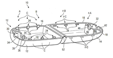
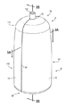
도 1은 본 개시의 일 실시 예에 따른 용기 절반부 및 상대되는 용기 절반부의 사시도이다.
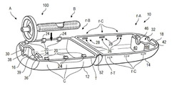
도 2a는 본 개시의 일 실시 예에 따른 용기 절반부에 삽입되는 SBoV(sleeve bag on valve) 어셈블리의 사시도이다.
도 2b는 본 개시의 일 실시 예에 따른 용기 절반부에 삽입된 SBoV 어셈블리의 사시도이다.
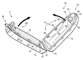
도 2c는 SBoV 어셈블리가 그 내부에 삽입되고, 상대되는 용기 절반부와 결합하는 용기 절반부의 사시도이다.
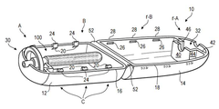
도 3은 본 개시의 일 실시 예에 따른 SBoV를 보유하는 용기를 형성하도록 결합된 용기 절반부 및 상대되는 용기 절반부의 사시도이다.
도 3a는 도 3의 3A-3A 선을 따라 취한 단면도이다.
도 3b는 도 3의 선 3B-3B 선을 따라 취한 단면도이다.
도 4는 본 개시의 일 실시 예에 따른 충전된 SBoV를 보유하는 용기의 3B-3B 선을 따라 취한 단면도이다.
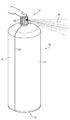
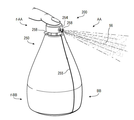
도 5는 본 개시의 일 실시 예에 따른 SBoV 어셈블리를 보유하고 유체 조성물을 분배하는 용기의 사시도이다.
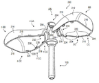
도 6은 본 개시의 일 실시 예에 따른 용기 절반부 및 상대되는 용기 절반부에 삽입되는 SBoV 어셈블리의 사시도이다.
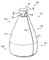
도 7은 본 개시의 일 실시 예에 따른 SBoV 어셈블리를 보유하는 용기의 사시도이다.
도 8은 도 7의 8-8 선을 따라 취한 단면도이다.
도 9는 본 개시의 일 실시 예에 따른 유체 조성물을 분사하는 SBoV 어셈블리를 보유하는 용기의 사시도이다.1 is a perspective view of a container half and an opposing container half according to one embodiment of the present disclosure;
2A is a perspective view of a sleeve bag on valve (SBoV) assembly that is inserted into a container half according to one embodiment of the present disclosure;
Figure 2B is a perspective view of an SBoV assembly inserted into a container half according to one embodiment of the present disclosure.
2C is a perspective view of a half of the container in which the SBoV assembly is inserted therein and engages with a container half that is opposed.
3 is a perspective view of a container half and a counterpart container half that are coupled to form a container holding an SBoV according to one embodiment of the present disclosure;
3A is a cross-sectional view taken along the
3B is a cross-sectional view taken along
4 is a cross-sectional view taken along
Figure 5 is a perspective view of a vessel having an SBoV assembly and dispensing a fluid composition according to one embodiment of the present disclosure;
Figure 6 is a perspective view of a SBoV assembly inserted into a container half and an opposing container half according to one embodiment of the present disclosure;
Figure 7 is a perspective view of a container having an SBoV assembly in accordance with one embodiment of the present disclosure;
8 is a sectional view taken along the line 8-8 in Fig.
9 is a perspective view of a container holding an SBoV assembly for ejecting a fluid composition according to an embodiment of the present disclosure;
본 개시는 장치를 제공한다. 일 실시 예에서, 장치는 가압된 물질(pressurized material) 용 디스펜서(dispenser)이다. 디스펜서는 노출된 에지(exposed edge)를 갖는 용기 절반부(container half) 및 노출된 에지에서 폐쇄 부재(closure member)를 포함한다. 용기 절반부는 용기 절반부의 내부의 상부에 컵 절반부(cup half)를 갖는다. 디스펜서는 상대되는(reciprocal) 노출된 에지를 갖는 상대되는 용기 절반부 및 상대되는 노출된 에지에서 상대되는 폐쇄 부재를 포함한다. 상대되는 용기는 상대되는 용기 절반부 내부의 상부에 상대되는 컵 절반부를 갖는다. 폐쇄 부재와 상대되는 폐쇄 부재는 노출된 에지를 따라 결합하여 용기 절반부를 상대되는 용기 절반부에 부착시키고 용기를 형성한다. 밸브 상의 슬리브 백(sleeve bag on valve assembly, SBoV) 어셈블리는 용기의 내부에 있다. SBoV 어셈블리에는 밸브 시트(seat)가 포함된다. 컵과 상대되는 컵은 밸브 시트를 지지하여 SBoV 어셈블리를 용기에 고정시킨다.The present disclosure provides an apparatus. In one embodiment, the apparatus is a dispenser for pressurized material. The dispenser includes a container half with an exposed edge and a closure member at the exposed edge. The container half has a cup half on top of the interior of the container half. The dispenser includes a counterpart container half having a reciprocal exposed edge and a closing member facing away from the opposing exposed edge. The container to be counterparted has a cup half which is opposed to the top of the interior of the container half to be countered. The closure member, which is opposed to the closure member, engages along the exposed edge to attach the container half to the counterpart half of the counterpart and form the container. The sleeve bag on valve assembly (SBoV) assembly is inside the container. The SBoV assembly includes a valve seat. The cup and the opposing cup support the valve seat to secure the SBoV assembly to the vessel.
1. 용기 절반부들1. Half of container
도 1 내지 도 5에 도시된 바와 같이, 디스펜서(10)는 용기 절반부(12) 및 상대되는 용기 절반부(14) (이하 "r-용기 절반부")를 포함한다. 용기 절반부(12)는 노출된 에지(16)를 갖고 r-용기 절반부(14)는 상대되는 노출된 에지(18) (이하, "r-노출된 에지")를 갖는다. 용기 절반부(12) 및 r-용기 절반부(14)는 집합적으로 "용기 절반부들" 또는 "절반부들"로 지칭될 수 있다. 유사하게, 노출된 에지(16) 및 r-노출된 에지(18)는 집합 적으로 "노출된 에지들" 또는 "에지들"로 지칭될 수 있다.1 to 5, the
절반부들(12, 14)은 강성(rigid) 재료 또는 반-강성 재료로 구성된다. 일 실시 예에서, 절반부들(12, 14)는 강성 재료로 구성된다. 절반부(12)의 재료는 절반부(14)의 재료와 동일하거나 상이할 수 있다. 절반부들(12, 14)에 적합한 재료의 비 제한적 예들은 중합체 재료, 금속, 목재, 유리, 판지(카드보드와 같은) 및 이들의 임의의 조합물을 포함한다.The
일 실시 예에서, 각각의 절반부(12, 14)는 중합체 재료로 구성된다. 적합한 중합체 재료의 비 제한적인 예들은 올레핀-계 중합체(olefin-based polymer), 나일론(nylon)(폴리아미드(polyamide)), 폴리에틸렌 테레프탈레이트(polyethylene terephthalate, PET), 폴리우레탄(polyurethane), 폴리카보네이트(polycarbonate), 폴리아크릴레이트(polyacrylate), 폴리메타크릴레이트(polymethacrylate), 환상 올레핀 공중합체(cyclic olefin copolymers)("COC", TOPAS 또는 APEL와 같은), 폴리에스테르(polyesters)(결정질 및 비정질), 코폴리에스테르 레진(copolyester resin)(예컨대, 폴리에틸렌 테레프탈레이트 글리콜-개질된(polyethylene terephthalate glycol-modified) "PETG"), 셀룰로오스 에스테르(cellulose esters)(예컨대, 폴리락트산(polylactic acid) 또는 "PLA"), 스티렌 아크릴로니트릴 레진(SAN), 아크릴로니트릴 부타디엔 스티렌(ABS), 폴리스티렌(polystyrene), 고 충격 폴리스티렌 (HIPS) 및 이들의 조합물을 포함한다. 필러(fillers), 착색제(colorants) 또는 안료(pigments), 안정제(stabilizers), 이형제(mold release agents) 등뿐만 아니라 유리 섬유와 같은 보강 보조제(reinforcement aids)도 추가 특성을 위해 중합체 재료에 첨가될 수 있다.In one embodiment, each of the
일 실시 예에서, 각각의 절반부(12, 14)는 올레핀-계(olefin-based) 중합체이다. 적합한 올레핀-계 중합체의 비 제한적인 예는 프로필렌-계(propylene-based) 중합체 및 에틸렌-계(propylene-based) 중합체를 포함한다. 적합한 프로필렌-계 중합체의 비 제한적인 예로는 프로필렌-계 중합체(플라스토머 및 엘라스토머를 포함하는), 랜덤 프로필렌 공중합체(random propylene copolymer), 프로필렌 호모중합체(propylene homopolymer), 및 프로필렌 충격 공중합체(propylene impact copolymer), 에틸렌-계 중합체와의 블렌드와 같은 프로필렌-계 중합체와 다른 올레핀-계 중합체와의 블렌드, 폴리에틸렌 엘라스토머, 및 열가소성 올레핀(TPO)을 포함한다.In one embodiment, each of the
적합한 에틸렌-계 중합체의 비 제한적인 예들은 에틸렌/C3-C10 α-올레핀 공중합체(선형 또는 분지형(branched)), 에틸렌/ C4-C10 α-올레핀 공중합체(선형 또는 분 지형), 고밀도 폴리에틸렌("HDPE"), 저밀도 폴리에틸렌("LDPE"), 선형 저밀도 폴리에틸렌("LLDPE"), 또는 중간 밀도 폴리에틸렌("MDPE")을 포함한다. 일 실시 예에서, 에틸렌-계 중합체는 적어도 0.94g/cc, 또는 적어도 0.94g/cc 내지 0.98g/cc의 밀도를 갖고, 0.1g/10분 내지 25g/10분의 용융 지수(melting index)를 갖는 HDPE이다.Non-limiting examples of suitable ethylene-based polymers include ethylene / C3-C10 alpha-olefin copolymers (linear or branched), ethylene / C4-C10 alpha-olefin copolymers (linear or branched), high density polyethylene ("HDPE"), low density polyethylene ("LDPE"), linear low density polyethylene ("LLDPE"), or medium density polyethylene ("MDPE"). In one embodiment, the ethylene-based polymer has a density of at least 0.94 g / cc, or at least 0.94 g / cc to 0.98 g / cc, and has a melting index of 0.1 g / 10 min to 25 g / Lt; / RTI >
중합체 재료는 단일 층 또는 구조, 또는 다층 구조일 수 있다. 중합체 재료가 다층 구조인 경우, 다층 구조는 공압출되거나(coextrud) 적층될 수 있다(laminated). 절반부들을 제조하기 위한 적합한 공정은 열 성형(thermoforming) 또는 사출 성형(injection molding)을 포함한다. 사출 성형은 다중-부품(multi-component) 사출 성형일 수 있으며 이중-사출 성형(bi-injection molding), 동시-사출 성형(co-injection molding), 다중-숏 사출 성형(multi-shot injection molding) 및/또는 삽입-성형(insert-molding)을 포함하고 또는 과-성형(over-molding)이 각 절반부를 만들기 위해 사용될 수 있다. 중합체 재료는 2 축 배향(biaxially oriented) 또는 1 축 배향(monoaxially oriented)일 수 있다.The polymeric material may be a single layer or structure, or a multi-layer structure. When the polymeric material is a multilayer structure, the multilayer structure may be coextruded or laminated. Suitable processes for making the halves include thermoforming or injection molding. Injection molding may be a multi-component injection molding and may be a bi-injection molding, a co-injection molding, a multi-shot injection molding, And / or insert-molding, or over-molding may be used to make each half. The polymeric material may be biaxially oriented or monoaxially oriented.
적합한 구조의 비 제한적 예는 높은 내 충격성(impact resistance)을 위한 엘라스토머(elastomer)와 같은 단단한/연성 재료로 구성된 외부 층을 갖는 딱딱한 내측 재료 내부(섬유 강화된 중합체 물질과 같은)를 갖는 다층 구조를 갖는 공동-사출된 몰드(co-injected mold) 절반부; 발포 플라스틱 코어 위에 매끄러운 외부 층을 동시에 주입; 과-성형된 사출 성형된 절반부(예를 들어, TPE 소프트 터치 그립을 추가하거나 절반부의 일부 또는 전체 영역에 장식을 추가)를 포함한다. 인-몰드 라벨(In-mold label)은 절반부들을 만드는 과정에서 추가될 수 있다.Non-limiting examples of suitable structures include a multi-layer structure having a rigid inner material interior (such as a fiber reinforced polymeric material) having an outer layer of a rigid / flexible material such as an elastomer for high impact resistance A co-injected mold half having an inner surface; Simultaneously injecting a smooth outer layer onto the foamed plastic core; Shaped injection molded half (e.g., adding a TPE soft touch grip or adding decoration to some or all of the half area). In-mold labels can be added in the process of making half-molds.
일 실시 예에서, 절반부들(12, 14)은 분배되는 유체 조성물에 대한 내 화학성(chemical resistance)을 갖는다.In one embodiment, the
일 실시 예에서, 절반부들(12, 14)은 동일한 중합체 재료로 구성된다. 동일한 중합체 재료의 절반부들(12, 14)에 대한 비 제한적 예는 열 성형 또는 블로 몰딩(blow molding) 공정 중 하나를 위해 DOW? HDPE DMDA 8007 NT 7(8.3 MI, 0.965g/cc); UNIVAL? DMDA 6400 NT 7 HDPE(0.80g/10분, 0.961g/cc); UNIVAL? DMDA 6200 NT 7 HDPE(0.38g/10분, 0.953g/cc)와 같은 에틸렌/헥센 공중합체와 같은 HDPE를 포함한다.In one embodiment, the
일 실시 예에서, 각각의 절반부(12, 14)는 각각의 두께(T)(절반부(12)에 대한 T, r-절반부(14)에 대한 r-T)를 갖는다. 각각의 절반부(12, 14) 평균 벽 두께의 평균 벽 두께는 0.075mm 또는 0.1mm 또는 0.15mm 또는 0.2mm 또는 0.4mm 또는 0.6mm 내지 1.0mm 또는 1.5mm 또는 2mm 또는 3.0mm이다. In one embodiment, each of the
도 1에 도시된 바와 같이, 각각의 절반부(12, 14)는 깊이를 갖고 부분 공동(cavity)을 형성한다. 절반부들(12, 14)는 서로 조립되어 전체 용기를 형성하도록 제조되거나 그렇지 않으면 구성된다. 절반부들이(12, 14)가 함께 모여서 에지(16)와 r-에지(18)가 상호 맞닿도록 서로 맞물릴 때, 절반부들(12, 14)은 협력하여 내부 챔버와 같은 폐쇄된 내부를 갖는 용기를 형성하는 것을 알 수 있다. 내부 챔버는 아래에 설명된 것처럼 SBoV를 포함하거나 그렇지 않으면 지원하도록 구성된다.As shown in Figure 1, each of the
용기를 닫을 때의 형상은 원통형 또는 직선형(rectilinear)일 수 있다. 용기는 정형화된 형상 또는 맞춤 형상과 같은 윤곽(contour) 또는 비정상적인(non-regular) 형상을 가질 수 있다.The shape of the container when closed can be cylindrical or rectilinear. The container may have a contour or a non-regular shape, such as a regular or custom shape.
도 1에서, 폐쇄 부재들(C)는 노출된 에지(16)를 따라 위치되고, 상대되는 폐쇄 부재들(r-C) (이하, "r-폐쇄 부재"라 함)는 r-노출된 에지(18)를 따라 위치된다. 폐쇄 부재 및 r-폐쇄 부재는 집합적으로 "폐쇄 부재들"이라고 할 수 있다. 도 1은 공간-분리 방식으로 노출된 에지(16)를 따라 배치된 다수의 폐쇄 부재들(C)과 유사한 공간-분리 방식으로 r-노출된 에지(18)를 따라 상대되는 폐쇄 부재들(r-C)을 도시한다. 폐쇄 부재들(C / r-C)은 영구 폐쇄(permanent closures) 또는 해제 가능 폐쇄(releasable closures)일 수 있다. 노출된 에지(16) 상의 각각의 폐쇄 부재(C)는 r-노출된 에지(18)를 따라 대응하는 상대되는 폐쇄 부재(r-C)를 갖는다. 절반부들(12, 14)이 아래에 설명된 결합 공정에서 함께 결합될 때, 각각의 폐쇄 부재(C) 및 각각의 상대되는 폐쇄 부재(r-C)는 서로 맞물리도록 위치되거나 또는 달리 서로 결합되도록 위치된다.1, the closing members C are positioned along the exposed edges 16 and the opposing closing members rC (hereinafter referred to as "r-closing members" ). The closure member and the r-closure member may collectively be referred to as "closure members ". Figure 1 shows a cross-sectional view of a closure member rC (Fig. ≪ RTI ID = 0.0 > ). Closure members C / r-C may be permanent closures or releasable closures. Each closure member C on the exposed
도 1은 3개의 폐쇄 부재들을(각각은 각각의 상대되는 폐쇄 부재들(r-C)을 가짐)를 도시하지만, 절반부(12)는 1, 또는 2, 또는 3, 또는 4, 또는 5, 또는 6, 또는 7, 또는 8, 또는9, 또는 10, 또는 그 이상의 폐쇄 부재들을 가질 수 있는 것으로 이해된다(각각은 절반부(14) 상의 각각의 r-폐쇄 부재를 가짐).Figure 1 shows three closure members (each having respective counter-closure members rC), but the
디스펜서(10)에 적합한 폐쇄/r-폐쇄 부재의 비 제한적 예는 스냅 핏(snap fit), 환형 스냅 조인트(annular snap joint)(2 개의 회전 대칭 부분들), 힌지-폐쇄(hinge-closure), 수-암 폐쇄(male-female closure), 후크 및 장착(hook and mount), 마찰 핏(friction fit) 및 이들의 조합을 포함한다. 추가적으로, 폐쇄/r-폐쇄 부재들은 접착 재료, 진동 용접, 열 스테킹 또는 교반 용접, 및 이들의 조합에 의해 서로 더 부착될 수 있다.Non-limiting examples of closure / r-closure members suitable for
일 실시 예에서, 폐쇄 부재들(C, r-C)은 맞물림 결합하여 스냅 핏 조인트(snap fit joint)를 형성한다. 도 1에 도시된 바와 같이, 폐쇄 부재(C)는 후크(24)를 갖는 돌출 부재(20)를 포함하고, 폐쇄 부재(r-C)는 도 2에 도시된 바와 같이 홀(28)을 갖는 유지 부재(retaining member)(26)를 포함한다.In one embodiment, the closure members C, r-C are mated to form a snap fit joint. 1, the closure member C includes a protruding
도 1에 도시된 바와 같이, 각각의 용기 절반부(12, 14)는 상부(A(절반부(12)), r-A(r-절반부(14))) 및 하부(B(절반부(12)) 및 r-B(r-절반부(14)))를 갖는다. 절반부(12)는 상부(A)에 컵(30)을 포함하고, r-절반부(14)는 상부(r-A)에 상대되는 컵(32) (이하, "r-컵")을 포함한다. 컵 및 r-컵은 집합적으로 "컵들(cups)"으로 지칭될 수 있다.As shown in Figure 1, each
2. 밸브(valve) 상의 슬리브(sleeve) 및 백(bag) 어셈블리(assembly)2. Sleeve and bag assembly on the valve.
디스펜서(10)는 도 2a, 도 2b, 도 2c 및 도 3에 도시된 바와 같이 밸브 상의 슬리브 및 백 어셈블리(또는 "SBoV")(100)를 포함한다. "SBoV" 및 "SBoV 어셈블리"라는 용어는 서로 바꿔 사용할 수 있다. 도 3b에 가장 잘 도시된 바와 같이, SBoV(100)는 밸브 하우징(102), 밸브 시트(104), 립 부분(105), 선택적 코어 튜브(106), 백(108) 및 탄성 슬리브(110)를 포함한다.The
밸브 하우징(102)은 도 3b에 도시된 바와 같이 밸브(112)를 보유하도록 구성된다. 도 3b는 스프링 밸브의 비 제한적인 예를 도시한다. 밸브 하우징(102)은 밸브 시트(104)에 견고하게 부착된다. 밸브 하우징(102)과 밸브 시트(104) 사이의 견고한 부착은 (i) 밸브 시트(104)를 밸브 하우징(102) 상으로 크림핑(crimping), (ii) 밸브 하우징(102)과 밸브 시트(104) 사이의 접착 부착, 및 (iii) (i)과 (ii)의 조합의 방법을 통해 발생될 수 있다.The
밸브 시트(104)는 강성 재료로 구성된다. 밸브 시트(104)에 적합한 재료의 비 제한적 예는 금속(스틸, 알루미늄) 및 중합체 재료를 포함한다.The
립 부분(105)는 강성 재료로 구성된다. 립 부분(105)에 적합한 재료의 비 제한적인 예는 금속(스틸, 알루미늄) 및 중합체 재료를 포함한다.The
SBoV(100)는 코어 튜브(106)를 포함하거나 포함하지 않을 수 있다. 실시 예에서, SBoV(100)는 코어 튜브를 갖지 않는다.The
일 실시 예에서, SBoV는 코어 튜브(106)를 포함한다. 도 3b에 도시된 바와 같이, 코어 튜브(106)는 코어 튜브(108)를 둘러싸는 백(108)의 내부에 존재한다. 백(108)은 폴리머 재료로 구성된 가요성 필름 구조(flexible film structure)이다. 백(108)은 단일 층의 가요성 필름 또는 다층의 가요성 필름일 수 있다. 백(108)에 적합한 폴리머 재료의 비 제한적 예는 프로필렌-계 폴리머(propylene-based polymer), 에틸렌-계 폴리머(ethylene-based polymer) 및 이들의 조합을 포함한다.In one embodiment, SBoV includes a
일 실시 예에서, SBoV는 코어 튜브(106)를 포함한다. 도 3b에 도시된 바와 같이, 코어 튜브(106)는 코어 튜브(106)를 둘러싸는 백(108)의 내부에 존재한다. 백(108)은 폴리머 재료로 구성된 가요성 필름 구조이다. 백 (108)은 단일 층의 가요성 필름 또는 다층의 가요성 필름일 수 있다. 백(108)에 적합한 폴리머 재료의 비 제한적 예는 프로필렌-계 폴리머, 에틸렌-계 폴리머 및 이들의 조합을 포함한다. 백(108)은 금속 호일(foil) 필름과 같은 장벽 층을 포함할 수 있다. 장벽 층은 가요성 필름에 적층될 수 있다. 유체 조성물에 노출된 백 내부 벽 및 다른 SBoV 구성들은 유체 조성물에 대한 내 화학성을 가질 수 있다.In one embodiment, SBoV includes a
일 실시 예에서, 백(108)은 100 마이크로 미터(㎛), 또는 200 ㎛ 내지 225 ㎛, 또는 250 ㎛의 두께를 갖는 다층 필름이고, 다층 필름은 화학적으로 내성이며 그 안에 함유된 유체 조성물에 대한 장벽이다. 추가 실시 예에서, 백(108)은 다층 필름이며, 산소 장벽 층, 이산화탄소 장벽 층, 수분 장벽 층 및 이들의 조합을 포함한다.In one embodiment, the
코어 튜브(106)는 속이 빈 형태(hollow)일수 있고 도는 고체일 수 있다. 코어 튜브 (106)는 포트(114)로의 그리고 포트(114)를 통한 제품(product)의 이동을 촉진시키기 위해 새로로 홈이 새겨지거나(fluted), 주름지거나(pleuted) 또는 축 방향으로 채널화될 수 있다.The
코어 튜브 (106)는 프로필렌-계 중합체 또는 HDPE와 같은 에틸렌-계 중합체로 구성될 수 있다. 대안적으로는, 코어 튜브(106)는 PETG, 폴리아미드(polyamide) 또는 다른 적절한 엔지니어링 열가소성 재료와 같은 비정질(amorphous) 폴리에스테르로 구성될 수 있다.The
일 실시 예에서, 코어 튜브(106)는 최대 8 내지 20 바(bar) 또는 그 이상까지의 비-분쇄가능(crushable) 재료로 구성된다.In one embodiment, the
코어 튜브(106)는 그 길이를 따라 균일한 직경을 가질 수 있다. 선택적으로, 코어 튜브(106)는 테이퍼질(tapered) 수 있다. 일 실시 예에서, 코어 튜브(106)는 테이퍼지고, 코어 튜브(106)의 직경은 코어 튜브의 근위 단부(또는 상 단부)에서 코어 튜브의 말단부로 이동하면서 점차적으로 증가한다. 코어 튜브의 말단부는 SBoV(100)가 떨어 뜨려 지도록(dropped) 지지 용기의 백(106)의 일체 성을 유지하는 것을 돕기 위해 둥글게 될 수 있다.The
코어 튜브(106)는 밸브 하우징(102)에 통합될 수 있거나, 또는 밸브 하우징(102)에 부착된 별도의 구성일 수 있다. 일 실시 예에서, 코어 튜브(106)는 밸브 하우징(102)과 별개의 부품이고 코어 튜브(106)는 속이 빈 형태이다. 코어 튜브(106)의 속이 빈 상 단부(109)는 도 3에 도시된 바와 같이 백(108)의 개구(opening)를 통해 연장한다. 코어 튜브(106)는 포트(port)(114) 및 포트 헤드(port head)(118)를 포함한다. 포트(114)는 속이 빈 상 단부(109) 아래에 있고 속이 빈 상 단부(109)와 유체 연통(fluid communication)한다. 백(108)의 개방 단부는 개스킷(gasket)(116)과 포트 헤드(118) 사이에 배치된다. 속이 빈 상 단부(109)는 포트(114)를 밸브(112)와 유체 연통 상태로 위치시키기 위해 밸브 하우징(102)의 하부 측 상의 밸브 채널(120)에 부착된다. 개스킷(116)은 포트 헤드(118)와 밸브 하우징(102) 사이의 백 개구를 샌드위치하여 백(108)을 밸브 하우징(102)에 밀폐 시키거나 견고하게 밀봉한다.The
다른 실시 예에서, 상 단부(109)와 밸브 채널(120) 사이의 견고한 부착은 고정되고 견고한 스냅 핏(snap fit)에 의한 것이다. 상 단부(109)를 위한 재료 구성은 코어 튜브(106)의 재료 구성과 다를 수 있다. 예를 들어, INFUSE? 에틸렌/알파-올레핀 멀티-블록 공중합체(ethylene/alpha-olefin multi-block copolymer)가 사용될 수 있다. 또한, 일 실시 예에서, 백(108)은 상 단부(109)에 대해 열 밀봉되어 밀폐된(hermetic) 밀봉을 제공할 수 있고, 그 후 밸브 채널(120)에 고정될 수 있다.In another embodiment, the rigid attachment between the
슬리브(110)는 엘라스토머 재료(elastomeric material)로 제조된 튜브 형 구조이다. 본 명세서에서 사용된 "엘라스토머 재료(elastomeric material)"는 응력(stress)의 적용으로 적어도 2 배의 길이로 신장될 수 있고 응력의 완화 후에 원래의 치수와 모양이 복원되어 양호한 회복력을 나타내는 재료이다. 엘라스토머 재로는 가황되거나(vulcanized) 가교 결합되거나(cross-linked) 그래프트된(grafted) 물질일 수도 있고 아닐 수도 있다.
일 실시 예에서 엘라스토머 재료는 가황된다.In one embodiment, the elastomeric material is vulcanized.
일 실시 예에서, 엘라스토머 재료는 선형 모듈러스(linear modulus) 대 연신률(elongation) 관계를 갖는다. 엘라스토머 재료는 유체 조성물에 대해 3 개월 또는 6 개월 내지 1 년의 컵 수명을 제공하기에 충분한 소량의 크립(creep) 또는 응력 완화를 나타낸다.In one embodiment, the elastomeric material has a linear modulus versus an elongation relationship. The elastomeric material exhibits a small amount of creep or stress relief sufficient to provide a cup life of 3 months or 6 months to 1 year for the fluid composition.
적합한 엘라스토머 재료의 비 제한적인 예는 에틸렌 공중합체(ethylene copolymers)(ENGAGE?와 같은), 에틸렌 올레핀 블록 공중합체(ethylene olefin block copolymers)(INFUSE ?와 같은), 에틸렌 프로필렌 디엔 단량체 삼원공중합체(ethylene propylene diene monomer terpolymer)(NORDEL ? EPDM 중합체와 같은 EPDM), 에틸렌 프로필렌(ethylene propylene)(EPM), 니트릴 고무(nitrile rubber), 수소화 니트릴 부타디엔 고무(HNBR), 폴리아크릴 고무(polyacrylic rubber), 실리콘 고무(silicone rubber), 플루오로실리콘 고무(fluorosilicone rubber), 플루오로엘라스토머(fluoroelastomers), 퍼플루오로 고무(perfluoro rubber), 천연 고무(즉, 천연 폴리이소프렌), 합성 폴리이소프렌(synthetic polyisoprene), 클로로핀(chloropene), 폴리클로로프렌(polychloroprene), 네오프렌(neoprene), 할로겐화 또는 비-할로겐화 부틸 고무(halogenated or non-halogenated butyl rubber)(이소부틸렌과 이소프렌의 공중합체(copolymer of isobutylene and isoprene)), 스티렌-부타디엔 고무(styrene-butadiene rubber), 에피클로로히드린(epichlorohydrin), 폴리에테르 블록 아미드(polyether block amides), 클로로술폰화 폴리에틸렌(chlorosulfonated polyethylene), 및 전술 한 것들의 임의의 조합물을 포함한다. 당 업계에 공지된 엘라스토머 첨가제는 항산화제(antioxidant) 및 가공 안정제(processing stabilizers)와 같은 이점을 제공하고, 안티 블록(antiblocks), 가황제(vulcanization agents)(전형적으로 황), 과산화물(peroxides), 촉진제(accelerators), 활성제(activators) 및 선택적 분산제(dispersants)와 같은 가교제(crosslink agents), 가공 보조제(processing aids), 가소제(plasticizers) 및 유기 점토(organoclays) 및 나노클레이(nanoclays)를 포함한 충전제(fillers), 카본 블랙(carbon black) 등은 엘라스토머 성분에 포함될 수 있다.Non-limiting examples of suitable elastomeric materials include, but are not limited to, ethylene copolymers (such as ENGAGE?), Ethylene olefin block copolymers (such as INFUSE?), Ethylene propylene diene monomer terpolymers propylene diene monomer terpolymer (EPDM such as NORDEL EPDM polymer), ethylene propylene (EPM), nitrile rubber, hydrogenated nitrile butadiene rubber (HNBR), polyacrylic rubber, silicone rubber but are not limited to, silicone rubber, fluorosilicone rubber, fluoroelastomers, perfluoro rubber, natural rubber (i.e., natural polyisoprene), synthetic polyisoprene, chlorophene, polychloroprene, neoprene, halogenated or non-halogenated butyl rubber ( Styrene-butadiene rubber, epichlorohydrin, polyether block amides, chlorosulfonated polyethylene < RTI ID = 0.0 > chlorosulfonated polyethylene, and any combination of the foregoing. The elastomeric additives known in the art provide advantages such as antioxidants and processing stabilizers and can be used in combination with antiblocks, vulcanization agents (typically sulfur), peroxides, Fillers, including crosslinkers, processing aids, plasticizers and organic clays, such as accelerators, activators and selective dispersants, and nanoclays, fillers, carbon black, and the like may be included in the elastomer component.
일 실시 예에서, 엘라스토머 물질은 나노 크기의 유기 점토 또는 나노 점토를 포함하며, 예를 들어 엘라스토머 복합체 또는 엘라스토머 나노 복합체에서 그러하다.In one embodiment, the elastomeric material comprises nano-sized organic clay or nano-clay, such as in an elastomeric composite or an elastomeric nanocomposite.
슬리브(110)는 반경 방향 및 축 방향으로 확장(및 수축) 또는 다른 방식으로 신장될 수 있다.
일 실시 예에서, 슬리브(110)는 반경 방향으로 확장 및 수축한다In one embodiment, the
슬리브(110)는 백(108)을 수용하고 백(108)이 분배될 유체 조성물(또는 유체 제품)으로 채워질 때 백(108)에 압력을 가하기 위한 크기 및 형상을 갖는다. 슬리브(110)는 균일한 두께를 가질 수도 있고 그렇지 않을 수도 있다. 슬리브(110)는 백(108)으로부터의 유체 조성물의 배출 사이클 중에 균일 한 압력을 부여할 수도 있고 균일한 압력을 부여하지 않을 수도 있다.
일 실시 예에서, 슬리브(110)는 전체 분배 사이클 동안(유체 조성물로 채워진 백이 유체 조성물을 비운 백으로) 균일한 압력을 제공한다. 슬리브(110)는 또한 분배한 후에 백에 양의 압력(positive pressure)을 제공하여 백(108)으로부터 모든 또는 실질적으로 모든 유체 조성물의 완전 배출을 보장한다. 슬리브(110)는 상부 및 하부에서 개방되거나 개방되지 않을 수 있다. 탄성 슬리브(110)는 백(108) 내의 모든 내용물들을 비우는 것을 보장하기 위해 백(108)보다 길 수 있다.In one embodiment, the
슬리브(110)는 백(108)으로부터 밸브(112)를 통해 제품을 방출하기에 충분한 힘을 가할만큼 충분히 두껍다. 밸브 스템(stem)에는 액츄에이터(actuator)가 있어 제품의 바람직한 스프레이 패턴 및 유속을 제어합니다.
밸브(112)가 작동될 때, 슬리브(110)는 균일하게 수축하여 백(108)으로부터 포트(114)를 통해 유체 조성물을 밀어내서, 밸브(112)를 통해 유체 조성물을 배출한다. 실시 예에서, 슬리브 (110)는 비 팽창 시 또는 그렇지 않은 경우 스트레칭되지 않을 때 두께를 가지며 "슬리브 벽 두께"로 표시된다. 슬리브 벽 두께는 약 1.5mm, 또는 2.0mm, 3.0mm, 또는 5.0mm, 또는 7.0mm, 내지 10.0mm, 또는 15.0mm, 또는 20.0mm부터 이다.When the
일 실시 예에서, 슬리브(110)는 200 %, 또는 250 %, 또는 300 % 내지 400 %, 또는 500 %, 또는 550 %, 또는 600 %, 또는 700 %보다 큰 연신률을 갖는 엘라스토머 재료로 제조된다.In one embodiment, the
일 실시 예에서, 엘라스토머 재료는 적어도 2 메가 파스칼(MPa), 또는 3MPa, 또는 5Mpa 내지 8Mpa, 또는 10Mpa, 또는 12Mpa 또는 14MPa, 또는 그 이상의 200 % 연실율에서 인장(tensile) 모듈러스를 갖는다.In one embodiment, the elastomeric material has a tensile modulus of at least 2 megapascals (MPa), or 3 MPa, or 5 MPa to 8 MPa, or 10 MPa, or 12 MPa or 14 MPa, or even 200%
일 실시 예에서, 슬리브(110)는 연신률 300 %, 또는 연신률 400 %에서 연신률 500 %로 확장(스트레칭)된다. 일 실시 예에서, 엘라스토머 재료는 400 % 연신률에서 20MPa 이상인 모듈러스를 가질 수 있다. 슬리브(110)는 또한 1 년 이내에 200 % 연신률의 인장 모듈러스가 25 % 변화 미만으로 이완될 수 있고 및/또는 4mm/일(day) 미만의 평균 크립률 변화를 나타낼 수 있다.In one embodiment, the
일 실시 예에서, 클립(122)은 도 3b에 도시된 바와 같이 슬리브(110)를 밸브 하우징(102)에 고정시킨다.In one embodiment, the
일 실시 예에서, 결합된(SBoV) 빈 백(108)에 의해 둘러싸인 코어 튜브(106)의 최소 직경은 스트레칭되지 않은 슬리브(110)의 직경보다 크다. 이러한 구성으로, 슬리브(110)는 백(108) 상에 일정한 양의 압력을 제공하여, 백(108)으로부터 모든 또는 실질적으로 모든 제품(유체 조성물)을 전체적으로 완전하게 배출할 때까지 백으로부터의 제품의 균일한 분배를 보장한다.In one embodiment, the minimum diameter of the
일 실시 예에서, 코어 튜브(106) 및 빈 백(108)(SBoV)은 확대되지 않은 슬리브(110)의 직경보다 10 %, 또는 15 %, 또는 20 % 내지 25 %, 또는 30 %, 또는 40 %, 또는 심지어 50 % 더 큰 결합된 최소 직경을 갖는다. 이러한 방식으로, 슬리브(110)는 백(108)에 일정한 양의(positive) 압력을 가한다.In one embodiment, the
일 실시 예에서, 슬리브는 코어/밸브 상의 백보다 길며, 백의 하부에서 포트(114)를 통해 그리고 밸브(112)를 통해 제품을 배출시키기에 충분한 양의 압력이 백의 하단에 가해지는 것을 보장한다.In one embodiment, the sleeve is longer than the bag on the core / valve, ensuring that a sufficient amount of pressure is applied to the bottom of the bag through the
유체 조성물은 (백(108)으로부터 분배하기 위해) 슬리브(110)에 의한 압축하는 압력 하에서 분배될 때 유체적으로(fluidly) 전달 가능한 물질(substance)이고, 유체 조성물은 밸브(112)가 개방될 때 압력 하에 백(108)으로부터 유출된다. 유체 조성물은 액체, 페이스트(paste), 발포체(foam), 분말(power) 또는 이들의 임의의 조합물일 수 있다. 적합한 유체 조성물의 비 제한적인 예는 다음을 포함 한다:The fluid composition is a fluidly transferable substance when dispensed under compression pressure by the sleeve 110 (to dispense from the bag 108), and the fluid composition is such that the
· 마요네즈, 케첩, 머스타드, 소스, 디저트(휘핑 크림), 스프레드(spreads), 기름(oil), 과자용 구성 요소(pastry components), 그리스(grease), 버터, 마가린, 소스, 유아 식, 샐러드 드레싱, 조미료(condiments), 음료, 시럽과 같은 식품;· Mayonnaise, ketchup, mustard, sauce, dessert (whipped cream), spreads, oil, pastry components, grease, butter, margarine, sauce, baby formula, salad dressing Food such as condiments, beverages, and syrup;
· 화장품 크림, 치약, 로션, 스킨 케어 제품, 헤어 젤, 퍼스널 케어 젤, 액체 비누, 액체 샴푸, 썬 케어 제품, 면도 크림, 탈취제와 같은 개인 위생 용품;Personal hygiene products such as cosmetic creams, toothpaste, lotions, skin care products, hair gels, personal care gels, liquid soaps, liquid shampoos, sun care products, shaving creams and deodorants;
· 의약품(medicaments), 약제(pharmaceutical) 및 약물(medications)(복용량 포장 포함) 및 연고(ointments), 구강 및 비강 스프레이와 같은 의료 제품(medical products);· Medical products such as medicaments, pharmaceuticals and medications (including dose packages) and ointments, mouth and nasal sprays;
· 광택제 및 유리, 욕실 및 가구 및 기타 세제, 살충제, 공기 청정제와 같은 가정용 제품들; 및· Household products such as polishes and glass, bath and furniture and other detergents, pesticides, air fresheners; And
· 도료(paints), 래커(lacquers), 접착제(glues), 그리스 및 기타 윤활제, 오일 밀봉제, 페이스트, 화학약품, 살충제, 제초제 및 소화 부품과 같은 산업용 제품.· Industrial products such as paints, lacquers, glues, greases and other lubricants, oil sealants, pastes, chemicals, insecticides, herbicides and fire extinguishers.
3. 용기의 제작3. Production of containers
도 2a 및 도 2b에 도시된 바와 같이, SBoV(100)는 절반부(12)에 위치한 컵(30) 내로 삽입된다. 컵(30)은 베이스(base)(34), 선반(shelf)(36) 및 베이스(34)와 선반(38) 사이에서 연장되는 벽(wall)(38)을 포함한다. 유사하게, r-컵(32)은 상대되는 베이스(40)("r-베이스"), 상대되는 선반(42)("r-선반") 및 상대되는 벽(44)("r-벽")을 포함한다. 밸브 시트(valve seat)(104)는 베이스(34)와 선반(36) 사이의 컵(30) 내로 삽입된다. 립 부분(105)은 선반(36) 상에 삽입된다. 삽입은 립 부분(105)이 상부(A)에서 절반부(12)의 내부 표면과 접하거나 다른 방식으로 접촉할 때 멈춘다. 컵(30)의 베이스는 밸브 하우징(102)의 일부가 연장되는 절반부 칼라(collar)(39)(r-컵(32)은 r-절반부 칼라(46)를 갖는다)를 갖는다. 도 2a, 도 2b 및 도 2c에 도시된 바와 같이, 컵(30)은 코어 튜브(106), 백(108) 및 슬리브(110)가 베이스(34) 아래에서 자유롭게 연장되는 상태에서 밸브 시트(104)의 반 직경을 지지한다.As shown in Figs. 2A and 2B, the
일 실시 예에서, 베이스/r-베이스(34, 40)는 제거되고 밸브 립(105)은 선반/r-선반(36, 42)에 의해지지 된다.In one embodiment, the base / r-
r-절반부(14)는 r-노출된 에지(18)를 노출된 에지(16)와의 협력적인 접촉 및 배치로 가져옴으로써 절반부(12)에 결합된다. 에지들(16, 18)이 서로 접근함에 따라, 후크(24)는 r-절반반의 내부 표면과 접촉하게 되고, 돌출 부재(20)가 반경 방향 내측으로 구부러지거나 그렇지 않으면 비껴진다.The r-
각각의 후크(24)는 그 각각의 유지 부재(26)의 홀(28) 내로 스냅 함으로써 후크(24)가 그 각각의 유지 부재(26)와 결합할 때까지 r-절반부(14)의 내면을 따라 계속된다. 후크(24)는 홀(28) 내로 스냅되어, 노출된 에지들(16, 18)을 전체적으로 완전히 맞물리게 하거나 서로 접촉시킨다. 돌출 부재(20)는 결합 작업 중에 잠시 비껴진다. 후크(24)가 각각의 유지 부재(26)와 결합하면, 돌출 부재(20)는 도 3a에 도시된 바와 같이 무력(stress-free) 상태로 복귀한다.Each
일 실시 예에서, 접착 재료는 노출된 에지(16)와 r-노출된 에지(18)에 인가되어 이들 사이의 부착을 촉진한다.In one embodiment, the adhesive material is applied to the exposed edges 16 and the r-exposed
결합 절차가 완료되면, 그 안에 SBoV(100)가 배치된 용기(50)가 도 3 내지 도 5에 도시된 바와 같이 형성된다. 용기(50)는 코어 튜브(106), 백(108) 및 슬리브(110)가 컵/r-컵(30, 32)으로부터 자유롭게 매달려있는 내부 챔버(51)를 포함한다. 내부 챔버(51)는 충진되거나 또는 부분적으로 충진된 백(108)을 수용하기에 충분한 체적을 제공한다.When the combining procedure is completed, a
용기(50)가 형성되면, 컵들의 베이스(16, 18)는 밸브 시트(104)의 전체 외주(circumference)를 지지한다. 유사하게, 각각의 컵들(16, 18)의 선반들(36, 44)은 립 부분(105)의 전체 외주를 지지한다. When the
이러한 방식으로, 폐쇄부(C) 및 상대되는 폐쇄부(r-C)는 절반부들(12, 14)을 서로 고정하여 전체 용기, 즉 SBOV(100)가 견고하게 배치되는 용기(50)를 형성한다.In this manner, the closure C and the opposing closure r-C secure the
각각의 절반부(12, 14)는 절반부 눈(eye)을 가지며, 이 절반부 눈은, 용기(50)의 형성 시, 도 3에 도시된 바와 같이 밸브(112)가 용기(50)의 상부로부터 바깥쪽으로 외측으로 연장되는 전체 눈(53)을 생성하도록 협력한다.Each of the
용기 절반부(16)는 비어있는 SBoV, 부분적으로 가득찬 SBoV 또는 가득찬 SBoV를 수신할 수 있다. 도 4는 백(108)이 유체 조성물로 충전된 후의 SBoV(100)를 도시한다. 도 4는 유체 조성물을 보유하는 백(108)을 갖는 스트리칭된 슬리브(110)을 도시하며, 슬리브(110)는 압력을 가한다.The
노출된 에지들(16, 18)(도 2a 내지 도 2c)은 용기(50)에 이음매(seam)(55)를 형성한다. 이음매(55)는 용기(50)의 길이 방향 축을 따라 연장된다. 일 실시 예에서, 본 가요성 용기(50)는 유체 조성물이 백으로부터 배출될 때 치수 또는 외관을 붕괴 시키거나 변화시키지 않고 그 형상을 유지한다(내부 진공 생성).The exposed edges 16,18 (Figs. 2A-2C) form a
일 실시 예에서, 밸브 캡(54)은 도 5에 도시된 바와 같이 밸브(112)에 부착된다. 밸브 캡(54)(도 5)은 용기(50)의 사용자가 밸브(112)를 작동시키고 유체 조성물(56)의 분사를 원하는 방향으로 유도할 수 있게 한다(뿐만 아니라 스프레이 패턴을 결정하고 및/또는 스프레이 유속을 결정할 수 있다).In one embodiment, the
일 실시 예에서, 내부 챔버(51)는 0.050 리터(L), 또는 0.1 L, 0.2 L, 또는 0.3 L, 또는 0.4 L, 또는 0.5 L, 또는 0.6 L, 또는 0.75 L, 또는 1.0 L, 또는 1.5 L, 또는 2.5 L, 또는 3.0 L, 또는 3.5 L, 또는 4.0 L, 또는 5.0 L, 또는 10.0 L 내지 20.0L, 또는 25L, 또는 28.5L의 체적을 갖는다. 추가 실시 예에서, 충전된 백(108)의 체적은 용기(50)의 체적보다 5 %, 또는 10 %, 또는 15 % 내지 20 %, 또는 25 % 또는 30 % 적다.In one embodiment, the
도 5는 유체 조성물(56)의 배출 동안 용기(50)를 지지하는 하부 세그먼트(58)를 도시한다. 절반부들(12, 14)은 SBoV(100) 및 용기(50)를 수직 위치 또는 실질적으로 수직 위치로 유지 또는 보유하기에 충분한 강도 및 강성을 제공한다. 그러므로, 일 실시 예에서, 용기(50)는 "스탠드-업 용기(stand-up container)"이다.FIG. 5 illustrates a
유체 조성물의 배출의 완료 또는 실질적 완료 후에, 백(108)은 밸브(112)를 통해 유체 조성물로 재-충전될 수 있다. 일 실시 예에서, 디스펜서(10)의 SBoV(100)는 1 회, 또는 2 회, 또는 3 회, 4 회, 또는 5 회 이상 재충전될 수 있다.After completion or substantial completion of the discharge of the fluid composition, the
밸브(112)는 유체 스트림, 겔, 로션, 크림, 발포체, 유체 스프레이 또는 미스트를 포함하지만 이에 한정되지 않는 소정의 방식으로 제품을 전달하기 위해 밸브에 고정된 다양한 형태의 액추에이터들(actuators) 또는 스프레이 캡들을 가질 수 있다.
4. 힌지(hinge)4. Hinge
일 실시 예에서, 힌지(52)는 도 1 내지 도 2c에 도시된 바와 같이 각각의 노출된 에지(16, 18) 부분을 따라 위치된다. 힌지(52)는 가요성 중합체 재료로 구성되고 도 1에 도시된 바와 같이 절반부(12)를 r-절반부(14)에 연결 시키거나 그렇지 않으면 부착시킨다. 일 실시 예에서 절반부(12), r-절반부(14) 및 힌지(52)는 동일한 중합체 재료로 구성된다.In one embodiment, the
절반부(12), r-절반부(14) 및 힌지(52)는 일체의(integral) 구성 요소일 수도 있고 아닐 수도 있다. 일 실시 예에서, 절반부(12), r-절반부(14) 및 힌지(52)는 단일 일체의 구성 요소이다.
도 1은 각 절반부들(12, 14)의 하부를 따라 위치한 힌지(52)를 도시하지만, 하나 이상의 힌지가 노출된 에지(16, 18)의 다른 부분을 따라 존재할 수 있는 것으로 이해된다.Figure 1 shows a
힌지(52)는 절반부들(12, 14) 사이의 유연한 움직임을 가능하게 한다. 힌지(52)는 용기(50)의 조립 중에 정렬(alignment)에 기여한다. 용기(50)의 제조 시, 힌지(52)는 하부 세그먼트(58)의 일부를 형성한다.The
5. 가요성 밸브 캡(flexible valve cap)5. Flexible valve cap
본 발명은 장치를 제공한다. 도 6 내지 도 9는 디스펜서(200)를 도시한다. 디스펜서(200)는 용기 절반부(212) 및 상대되는 용기 절반부(214)(이하, "r-용기 절반부"라 함)를 포함한다. 용기 절반부(212)는 노출된 에지(216)를 갖고 r-용기 절반부(214)는 상대되는 노출된 에지(218)(이하, "r-노출된 에지")를 갖는다. 용기 절반부(212), r-용기 절반부(214), 노출된 에지(216), r-노출된 에지(218)는 "용기 절반부들" 또는 "절반부들"이라고 총칭하여 본 명세서에서 앞서 개시된 바와 같이, 각각의 용기 절반부, 노출된 에지일 수 있다. 유사하게, 노출된 에지(216) 및 r-노출된 에지(218)는 집합적으로 "노출된 에지들"또는 "에지들"로 지칭될 수 있다.The present invention provides an apparatus. Figures 6-9 illustrate the
디스펜서(200)는 노출된 에지(216)를 따라 위치된 폐쇄 부재(CC) 및 r-노출된 에지(218)를 따라 위치된 상대되는 폐쇄 부재(이후, "r-폐쇄 부재")를 포함한다. 폐쇄 부재들(CC, r-CC)는 전술한 바와 같이 임의의 각각의 폐쇄 부재 또는 상대되는 폐쇄 부재가 될 수 있다. 일 실시 예에서, 폐쇄 부재 (CC)는 후크(224)를 갖는 돌출 부재(220)를 포함하고, r-폐쇄 부재(r-CC)는 홀(또는 함몰부(indent))(228)을 갖는 유지 부재(226)를 포함한다.The
도 6 내지 도 9에 도시된 바와 같이, 각각의 용기 절반부(212, 214)는 상부(AA(절반부(212)), r-AA(r-절반부(214))) 및 하부(BB(절반부(212)) 및 r-BB(r-절반부(214)))를 갖는다. 절반부(212)는 상부(AA)에 컵(230)을 포함하고, r-절반부(214)는 상부(r-AA)에 상대되는 컵(232)(이하 "r-컵")을 포함한다. 컵들(230, 232)은 앞서 본 명세서에 개시된 바와 같은 임의의 컵/r-컵일 수 있다.As shown in Figs. 6-9, each
디스펜서(200)는 밸브 캡(254)을 포함한다. 밸브 캡(254)은 중합체 재료로 구성되며, 도 6 내지 도8에 도시된 바와 같이 제1 레그(leg)(256) 및 제2 레그(258)를 포함한다. 제1 레그(256)는 용기 절반부(216)에 유연하게 부착된다. 제2 레그(258)는 제1 레그 대향 측에서 밸브 캡으로부터 연장되고, 제2 레그(258)는 r-용기 절반부(218)에 유연하게 부착된다. 본 명세서에서 사용되는 용어 "유연하게 부착된(flexibly attached)"은 밸브 캡(254)과 각각의 절반부(212, 214) 사이의 다음과 같은 움직임을 가능하게 하는 구조적 연결을 의미한다: (i) 밸브 캡과 각각의 절반부 사이의 힌지 움직임(측면), (ii) 밸브 캡과 각 절반 사이의 비틀림 움직임(뒤틀림), (iii) 밸브 캡과 각 절반 사이의 압축 운동(구부림), 및 (iv) (i) 내지 (Ⅲ)의 임의의 조합. 다시 말하면, 레그들(256, 258)는 밸브 캡(254)이 절반부들(212, 214)에 대해 구부러지거나 비틀리거나 압축될 수 있게 한다. 레그들(256, 258)는 또한 밸브 캡(254)이 밸브(112)에 대해 그리고 절반부들(212, 214)에 대해 압축(구부림)될 수 있게 한다.The
SBoV(100)는 절반부(212)에 위치한 컵(230) 내로 삽입된다. 도 6, 도 8에 도시된 바와 같이, 컵(230)은 베이스(234), 선반(236) 및 베이스(234)와 선반(236) 사이에서 연장되는 벽(238)을 포함한다. 유사하게, r-컵(232)은 상대되는 베이스(240)("r-베이스"), 상대되는 선반(242)("r-선반") 및 상대되는 벽(244)("r-벽")을 포함한다. 밸브 시트(104)는 베이스(234)와 선반(236) 사이의 컵(230) 내로 삽입된다. 립 부분(105)은 선반(236)과 베이스(234) 사이에 삽입된다. 컵의 베이스(230)(및 베이스 또는 r-컵(232)) 각각은 코어 튜브, 백, 및 슬리브가 연장되는 절반부 칼라(collar)를 갖는다.The
SBoV(100)는, 도 6 내지 도 8에 도시된 바와 같이, 내부 밸브 캡(254) 내로 삽입된 밸브(112)와 함께 절반부들(212, 214) 사이에 배치된다. 밸브 캡(254)은 밸브(212)를 수용하고 밸브(212)와 밸브 캡(254) 사이에 유체 연통을 제공하는 벽(260)을 포함하고, 도 8에 도시된 바와 같이, 유체가 밸브(112)를 통해 그리고 밸브 캡(254)을 통해 분사될 수 있게 한다.The
절반부들(212, 214)은 함께 결합되고 전술한 바와 같이 폐쇄된다. r-절반부(214)은 r-노출된 에지(218)를 노출된 에지(216)와의 협동 접촉 및 배치로 가져옴으로써 절반부(212)에 결합된다. 에지들(216, 218)이 서로 접근함에 따라, 후크(224)은 r-절반부의 내부 표면과 접촉하여 돌출 부재(220)가 반경 방향 내측으로 구부러지거나 그렇지 않으면 비껴지게 한다.The
각각의 후크(224)는 그 각각의 유지 부재(226)의 홀(또는 오목부)(228) 내로 스냅함으로써 후크(224)가 그 각각의 유지 부재(226)와 결합할 때까지 그 내향 움직임을 계속한다. 후크(224)는 홀 내로 스냅되어, 노출된 에지들(216, 218)을 전체적으로 완전하게 결합 시키거나 서로 접촉시킨다. 돌출 부재(220)는 결합 작업 중에 잠시 비껴지고, 일단 휴크(224)가 각각의 유지 부재(226)와 결합하면 돌출 부재(220)는 무-응력(stress-free) 상태로 되돌아 간다.Each
용기(250)가 형성될 때, 컵들(230, 232)의 베이스는 밸브 시트(104)의 전체 외주를 지지한다. 유사하게, 립 부분(105)의 전체 외주는 선반들(236, 242)과 각각의 베이스들(234, 240) 사이에서 지지된다.When the
이런 식으로, 폐쇄(C) 및 상호 폐쇄(r-C)는 절반부들(212, 214)을 서로 고정하여 SBoV(100)가 견고하게 배치되는 전체 용기("용기(250)")를 형성한다. 에지들(216, 218)의 내향 움직임은 서로 정렬되어 맞물린다.In this way, the closure C and the interlocking (r-C) secure the
도 9에 도시된 바와 같이, 제1 레그(256) 및 제2 레그(258)는 밸브 캡(254)에 압력을 가하여(사용자의 손가락으로 표시) 밸브 캡(254)을 하향으로 가압하여 밸브를 작동시키고 유체 조성물(56)의 분무를 분배한다.9, the
SBoV 용 신청자의 2-피스 스냅 핏 지지 용기는 최종 사용 요구 사항 및/또는 사용자 선호도(인체 공학, 미학 등)에 맞춰 특별히 설계할 수 있는 수많은 용기 구성으로 SBoV 지지 용기를 제공할 수 있는 능력을 제공한다.Applicant's two-piece snap fit support container for SBoV provides the ability to provide SBoV support containers in numerous container configurations that can be specifically designed for end-use requirements and / or user preferences (ergonomics, aesthetics, etc.) do.
정의 및 테스트 방법Define and test methods
여기에 개시된 수치 범위는 낮은 값과 높은 값으로부터의 모든 값을 포함한다. 명시적 값(예를 들어, 1, 또는 2, 또는 3 내지 5, 또는 6, 또는 7)을 포함하는 범위의 경우 두 개의 명시적 값 사이의 하위 범위(예를 들어, 1 내지 2; 2 내지 6; 5 내지 7; 3 내지 7; 5 내지 6; 등)가 포함됩니다.The numerical ranges disclosed herein include all values from a low value and a high value. For ranges that include an explicit value (e.g., 1 or 2, or 3 to 5, or 6, or 7), a subrange between two explicit values (e.g., 1 to 2; 6; 5 to 7; 3 to 7; 5 to 6; etc.).
달리 명시되지 않는 한, 문맥으로부터 암묵적으로 또는 당 업계에서 통상적인 것으로서, 모든 부분 및 퍼센트는 중량(weight)에 기초하고, 모든 테스트 방법은 이 개시의 출원일 현재입니다.Unless otherwise specified, all parts and percentages are based on weight, either implicitly or as is conventional in the art, and all test methods are current as of the filing date of this disclosure.
본원에 사용된 용어 "조성물(composition)"은 반응 생성물로서의 컵으로서 조성물을 포함하는 물질의 혼합물 및 조성물의 물질로부터 형성된 분해 생성물을 지칭한다.The term " composition " as used herein refers to a mixture of materials comprising the composition as a cup as a reaction product and to a decomposition product formed from the materials of the composition.
"포함하는(comprising, including)", "갖는(having)" 및 그 파생어 등은 추가 구성 요소, 단계 또는 절차의 존재를 배제하지 않는다. 의심의 여지를 피하기 위해, "포함하는"이라는 용어의 사용을 통해 청구된 모든 조성물은 달리 언급되지 않는 한, 중합체성 또는 기타의 어떠한 추가의 첨가제, 보조제 또는 화합물을 포함할 수 있다. 대조적으로, "본질적으로 구성되는(consisting essentially of)"이라는 용어는 조작 가능성에 필수적이지 않은 것들을 제외하고, 다른 구성 요소, 단계 또는 절차를 후속 인용의 범위에서 제외한다. "구성되는"이라는 용어는 구체적으로 묘사되거나 나열되지 않은 구성 요소, 단계 또는 절차를 제외한다.&Quot; comprising, "" having ", " having ", and derivatives, etc. do not exclude the presence of additional elements, steps or procedures. In order to avoid doubt, all compositions claimed through the use of the term "comprising" may include polymeric or any other additive, adjuvant or compound, unless otherwise stated. In contrast, the term " consisting essentially of "excludes other elements, steps, or procedures from the scope of the following citations, except those that are not essential to operability. The term "comprising" excludes elements, steps or procedures not specifically depicted or listed.
"크립(creep)" 또는 "크립 속도(율)(creep rate)"라는 용어는 엘라스토머 재료의 완화 특성(relaxation characteristic)이다. 본 명세서에서 사용된 "크립"은 일정한 응력을 유지하면서 시간에 따른 변형(strain)의 변화를 나타낸다.The term "creep" or "creep rate" is a relaxation characteristic of an elastomeric material. As used herein, "creep" refers to a change in strain over time while maintaining a constant stress.
밀도는 ASTM D 792에 따라 측정된다.The density is measured in accordance with ASTM D 792.
어구 "엘라스토머 복합체"는 또한 엘라스토머 나노복합체, 나노복합체 및 나노복합체 조성물을 포함한다. 용어 "나노필러(nanofiller)"는 나노복합체 제조에 유용한 나노입자를 기술하기 위해 당해 기술 분야에서 집합적으로 사용된다. 이러한 입자들는 층들을 포함하는 입자들로부터 수득된 층들 또는 혈소판(platelet) 입자들(혈소판들)을 포함할 수 있으며, 적층된(stacked), 인터카레이트된(intercalated) 또는 박리된(exfoliated) 상태로 존재할 수 있다. 일부 경우, 나노충전제는 나노클레이(또는 NC)로서 당 업계에 공지된 클레이 재료의 입자를 포함한다.The phrase "elastomer complex" also includes elastomeric nanocomposites, nanocomposites and nanocomposite compositions. The term "nanofiller" is used collectively in the art to describe nanoparticles useful for the preparation of nanocomposites. These particles may comprise layers or platelet particles (platelets) obtained from particles comprising layers and may be stacked, intercalated or exfoliated Lt; / RTI > In some cases, the nanofiller comprises particles of a clay material known in the art as a nanoclay (or NC).
연신률은 ASTM D 412에 따라 결정된다. 연신률은 원래 길이의 백분율로 표시된 표본(즉, 엘라스토머 복합체)의 균일한 섹션의 확대이며, 다음과 같다:The elongation is determined according to ASTM D 412. Elongation is the expansion of a uniform section of the specimen (i. E., The elastomeric composite), expressed as a percentage of its original length, as follows:

본원에서 사용되는 "에틸렌-계 중합체(ethylene-based polymer)"는 50 몰 % 초과의 중합된 에틸렌 단량체를 함유하고(중합성 단량체의 총량 기준), 선택적으로 적어도 하나의 공단량체를 함유할 수 있는 중합체이다.An "ethylene-based polymer" as used herein refers to a copolymer containing 50 mol% or more of polymerized ethylene monomers (based on the total amount of polymerizable monomers), optionally containing at least one comonomer Lt; / RTI >
용융 유속(melt flow rate, MFR)은 ASTM D 1238, 조건 280℃/2.16kg(g/10분)에 따라 측정된다.The melt flow rate (MFR) is measured according to ASTM D 1238, condition 280 ° C / 2.16 kg (g / 10 min).
용융 지수(melt index, MI)는 ASTM D 1238, 조건 190℃/2.16kg(g/10분)에 따라 측정된다.The melt index (MI) is measured according to ASTM D 1238, condition 190 캜 / 2.16 kg (g / 10 min).
본원에서 사용되는 "올레핀-계 중합체(olefin-based polymer)"는 50 몰 % 초과의 중합된 올레핀 단량체를 함유하고(중합성 단량체의 총량 기준), 선택적으로 적어도 하나의 공단량체를 함유할 수 있는 중합체이다. 올레핀-계 중합체의 비 제한적인 예로는 에틸렌-계 중합체 및 프로필렌-계 중합체가 있다.As used herein, an " olefin-based polymer "refers to an olefin-based polymer that contains more than 50 mole percent of polymerized olefin monomers (based on the total amount of polymerizable monomers), and may optionally contain at least one comonomer Lt; / RTI > Non-limiting examples of olefin-based polymers include ethylene-based polymers and propylene-based polymers.
"중합체(polymer)"는 중합 형태로 중합체를 구성하는 다중 및/또는 반복 "유닛들" 또는 "머(mer) 유닛들"을 제공하는 동일하거나 상이한 유형의 단량체들을 중합함으로써 제조된 화합물이다. 따라서, 일반적인 용어 중합체는 단 하나의 유형의 단량체만으로 제조된 중합체를 지칭하게 위해 통상적으로 사용되는 호모중합체(homopolymer)라는 용어를 포함하며, 일반적으로 적어도 2 가지 유형의 단량체들로부터 제조된 중합체를 지칭하기 위해 통상적으로 사용되는 공중합체(copolymer)라는 용어를 포함한다. 또한 모든 형태의 공중합체, 예를 들면 무작위, 블록 등을 포함한다. "에틸렌/α-올레핀 중합체" 및 "프로필렌/α-올레핀 중합체"라는 용어는 각각 에틸렌 및 프로필렌 및 하나 이상의 추가의 중합 가능한 알파-올레핀 단량체를 중합시킴으로써 제조된 전술한 바와 같은 공중합체를 나타낸다. 중합체는 종종 특정 단량체 내용물 등을 "함유하는" 특정 단량체 또는 단량체 유형에 "기초하여" 하나 이상의 특정 단량체로 "만들어 지기도하지만", 이 문맥에서 "단량체"라는 용어는 특정 단량체의 중합 잔류 물을 말하며 비 중합 화 종은 언급하지 않음을 주목해야 한다. 일반적으로, 본원에서 중합체는 상응하는 단량체의 중합 형태인 "유닛들"에 기초한 것으로 언급된다."Polymer" is a compound made by polymerizing the same or different types of monomers to provide multiple and / or repeating "units" or "mer units" Thus, a generic term polymer includes the term homopolymer conventionally used to refer to a polymer made with only one type of monomer, and generally refers to a polymer made from at least two types of monomers The term " copolymer " It also includes all types of copolymers, such as random, block, and the like. The terms "ethylene / alpha -olefin polymer" and "propylene / alpha -olefin polymer" refer to the copolymers described above prepared by polymerizing ethylene and propylene and at least one additional polymerizable alpha-olefin monomer, respectively. The term "monomer" in this context refers to a polymeric residue of a particular monomer, although the term " polymer " is sometimes "made up of one or more specific monomers" It should be noted that non-polymerized species are not mentioned. In general, the polymers herein are referred to as being based on "units" which are polymeric forms of the corresponding monomers.
"프로필렌-계 중합체"는 50 몰 % 초과의 중합된 프로필렌 단량체를 함유하고(중합성 단량체의 총량 기준), 선택적으로 적어도 하나의 공단량체를 함유할 수 있는 중합체이다."Propylene-based polymer" is a polymer that contains more than 50 mol% of polymerized propylene monomer (based on the total amount of polymerizable monomers), and optionally may contain at least one comonomer.
본 명세서에서 사용되는 용어 "응력 완화(stress relaxation)"는 단순히 용어 "완화"로도 사용되며 일정한 변형을 유지하면서 응력의 시간 의존 변화를 기술한다. 변형된 엘라스토머 물질의 응력은 엘라스토머 내에서 발생하는 분자 이완 과정으로 인해 시간에 따라 감소한다.As used herein, the term " stress relaxation "is also used simply as the term " relaxation " and describes a time-dependent change in stress while maintaining a constant strain. The stress of the modified elastomeric material decreases with time due to the molecular relaxation process occurring in the elastomer.
인장 강도 및 모듈러스- "인장 강도"는 후크의 법칙(Hooke's Law)이 유효한 저 변형(strain)에서 일축 장력에서의 응력-대-변형 곡선의 선형 기울기로 정의되는 탄성 재료의 강성을 측정한 것이다. 이 값은, MPa에서, 엘라스토머 합성물이 파열되기 전에 스트레칭하는 동안 인가된 최대 인장 응력을 나타낸다. "모듈러스"는 주어진 연신률에서 엘라스토머 재료의 인장 응력, 즉 엘라스토머 재료의 균일한 섹션을 주어진 연신률로 스트레칭하는데 필요한 응력이다. 이 값은 복합체의 기능 강도를 나타낸다. M100은 100 % 연신률에서의 인장 응력이고, M200은 200 % 연신률에서의 인장 응력이다. 인장 강도 및 모듈러스는 ASTM D 412에 따라 측정된다.Tensile Strength and Modulus- "Tensile Strength" is a measure of the stiffness of an elastic material defined by the linear slope of the stress-versus-strain curve at uniaxial tension at a low strain at which Hooke's Law is valid. This value, at MPa, represents the maximum tensile stress applied during stretching before the elastomeric composition is ruptured. "Modulus" is the tensile stress of the elastomeric material at a given elongation, the stress required to stretch a uniform section of the elastomeric material to a given elongation. This value represents the functional strength of the complex. M100 is tensile stress at 100% elongation, and M200 is tensile stress at 200% elongation. Tensile strength and modulus are measured according to ASTM D 412.
본원에서 사용된 Tm 또는 "용융 점(melting point)"(플롯된 DSC 곡선의 형상과 관련하여 용융 피크라고도 함)은 전형적으로 USP 5,783,638에 기재된 바와 같이 폴리올레핀의 용융 점 또는 피크를 측정하기 위한 DSC(Differential Scanning Calorimetry) 기술에 의해 측정된다. 2 개 이상의 폴리올레핀을 포함하는 다수의 블렌드들(blends)은 하나 이상의 용융 점 또는 피크를 가질 것이고, 많은 개별 폴리올레핀은 단지 하나의 용융 점 또는 피크를 포함할 것이다.The Tm or "melting point" (also referred to as the melting peak in relation to the shape of the plotted DSC curve) used herein is typically measured using a DSC Differential Scanning Calorimetry) technique. A number of blends comprising two or more polyolefins will have at least one melting point or peak and many individual polyolefins will contain only one melting point or peak.
이하, 본 개시의 실시 예들을 이하의 실시 예들에서 상세히 기술될 것이다.Hereinafter, embodiments of the present disclosure will be described in detail in the following embodiments.
실시 예들Examples
도 1 내지 도 5에 도시된 바와 같이 상대되는 용기 절반부(14)에 힌지 결합된 용기 절반부(12)에 대한 모델은 'SolidWorks'라 불리는 3 차원(3D) 솔리드 모델링 소프트웨어로 설계된다. 디자인 파일은 '.stl' 형식으로 변환되어 3D 프린터(STRATASYS Connex 기계)로 업로드 된다. 3D 프린터는 모델을 층들로 분할한 다음 나중에 인쇄한다. 3D 프린터 헤드는 순차적인 아크릴 층들을 배치하고 아크릴을 가볍게 비추어 경화시킨다. 그 다음 3D 프린터는 CAD 모델에 정의된 바와 같이 상대되는 용기 절반부(14)에 힌지 결합된 용기 절반부(12)를 형성하도록 다른 층을 배치한다. 단계들은:The model for the
1) 3D CAD 소프트웨어에서 용기 절반부/상대되는 용기 절반부 설계;1) container half / compartment half design in 3D CAD software;
2) .slt 포멧으로 변환2) Convert to .slt format
3) 3D 프린터에서 절반부들을 인쇄; 및3) print half the shots in 3D printers; And
4) 용기 절반부들, 3D 인쇄의 가공품으로부터 지지 재료를 세척한다.4) Clean the support material from the container halves, the workpiece in 3D printing.
완성된 용기 절반부/상대되는 용기 절반부는 각각 0.1 인치의 공칭 벽 두께를 갖는다.The finished container halves / opposing container halves each have a nominal wall thickness of 0.1 inches.
밸브 어셈블리 상의 슬리브 백은 도 2 내지 도 2c에 도시된 바와 같이 밸브 시트를 용기 절반부의 컵 내로 삽입함으로써 용기 절반부에 배치된다. 밸브 시트의 립 부분은 용기 절반부의 선반에 의해 지지 된다. 그런 다음 상대되는 용기 절반부가 용기 절반부에 닫힌다. 용기 절반부의 노출된 에지를 따라 이격된 후크들은 상대되는 용기 절반부의 상대되는 노출된 에지를 따라 대응하는 홀들 내로 잠김으로써, 그에 의해 디스펜서를 형성하도록 폐쇄된 용기의 내부 챔버 내의 밸브 에셈블리 상에 슬리브 백을 고정시킨다. 완성된 디스펜서는 그 베이스에 놓여있다. 디스펜서는 똑바로 세우고(상부 상의 밸브), 수직으로 밸브 어셈블리 상의 슬리브 백을 안정적으로 견고하게 지지한다.The sleeve bag on the valve assembly is disposed in the container half by inserting the valve seat into the cup of the container half as shown in Figures 2 to 2C. The lip portion of the valve seat is supported by the shelf of the container half. The opposing container half is then closed in the container half. The hooks spaced along the exposed edges of the container halves are locked into corresponding holes along the opposite exposed edges of the opposing container halves so as to form the dispenser, Fix the bag. The completed dispenser lies on its base. The dispenser stands upright (valve on the top) and stably supports the sleeve back on the valve assembly vertically.
본 개시는 본 명세서에 포함된 실시 예 및 예시에 한정되지 않으며, 하기 청구 범위의 범주에 속하는 실시 예의 일부 및 다른 실시 예의 구성 요소의 조합을 포함하는 이들 실시 예의 수정된 형태를 포함한다.This disclosure is not limited to the embodiments and examples contained in this specification and includes modified forms of these embodiments that include some of the embodiments falling within the scope of the following claims and combinations of elements of other embodiments.
Claims (17)
노출된 에지(edge) 및 상기 노출된 에지에서 폐쇄 부재(closure member)를 갖는 용기 절반부(container half)로서, 내부 상단 부분에 컵 절반부(cup half)를 갖는, 상기 용기 절반부;
상대되는(reciprocal) 노출된 에지 및 상기 상대되는 노출된 에지에서의 상대되는 폐쇄 부재, 내부의 상단 부분에서의 상대되는 컵 절반부를 갖는 상대되는 용기 절반부;
상기 폐쇄 부재 및 상기 상대되는 폐쇄 부재는 상기 노출된 에지들을 따라 짝을 이루어 결합되어 상기 용기 절반부가 상기 상대되는 용기 절반부에 부착되여 용기를 형성하고;
상기 용기의 내부에 밸브 상의 슬리브 백(sleeve bag on valve: SBoV) 어셈블리로서, 밸브 시트(valve seat)를 포함하는, 상기 SBoV 어셈블리를 포함하되;
상기 컵 및 상기 상대되는 컵은 상기 밸브 시트를 지지하여 상기 SBoV 어셈블리를 상기 용기에 고정하는, 디스펜서.A dispenser for a pressurized material, the dispenser comprising:
A container half having an exposed edge and a closure member at the exposed edge, the container half having a cup half at an inner top portion;
A counterpart container half having a reciprocal exposed edge and a corresponding closing member at the opposing exposed edge, a relative cup half at an upper portion of the interior;
The closure member and the opposing closure member are mated together along the exposed edges to attach the container half to the counterpart container half to form a container;
Said SBoV assembly comprising a valve seat as a sleeve bag on valve (SBoV) assembly within said vessel;
Wherein the cup and the opposing cup support the valve seat to secure the SBoV assembly to the vessel.
노출된 에지 및 상기 노출된 에지에서의 폐쇄 부재를 갖는 용기 절반부로서, 내부 상단 부분에 컵 절반부를 갖는, 상기 용기 절반부;
상대되는 노출된 에지 및 상기 상대되는 노출된 에지에서의 상대되는 폐쇄 부재, 내부의 상단 부분에서의 상대되는 컵 절반부를 갖는 상대되는 용기 절반부;
상기 노출된 에지들을 따라 짝을 이루어 결합되어, 상기 용기 절반부를 상기 상대되는 용기 절반부에 부착시켜 용기를 형성하는 상기 폐쇄 부재와 상기 상대되는 폐쇄 부재;
상기 용기 내부에 밸브 상의 슬리브 백(sleeve bag on valve: SBoV) 어셈블리로서, 상기 용기의 상단 부분으로부터 연장되는 밸브를 포함하는, 상기 SBoV 어셈블리; 및
상기 용기 절반부에 유연하게 부착되는 제1 레그(leg) 및 상기 상대되는 용기 절반부에 유연하게 부착되는 제2 레그를 포함하는 밸브 캡으로서, 상기 밸브와 유체 연통(fluid communication)하는, 상기 밸브 캡을 포함하는, 디스펜서.A dispenser for pressurized material comprising:
A container half having an exposed edge and a closing member at the exposed edge, the container half having a cup half at an inner upper portion;
A counterpart container half having an opposing exposed edge and an opposing closing member at said opposing exposed edge, a counterpart half of the cup at the top portion of the interior;
A closing member that is coupled in pairs along the exposed edges to attach the container half to the opposing container half to form a container;
A sleeve valve on valve (SBoV) assembly within the vessel, the valve comprising a valve extending from an upper portion of the vessel; And
A valve cap including a first leg flexibly attached to the container half and a second leg flexibly attached to the opposing container half, the valve cap fluidly communicating with the valve, A dispenser comprising a cap.
상기 컵 및 상기 상대되는 컵은 상기 밸브 시트를 지지하여 상기 SBoV 어셈블리를 상기 용기에 고정시키는, 디스펜서.The system of claim 9, wherein the SBoV assembly comprises a valve seat; And
Wherein the cup and the opposing cup support the valve seat to secure the SBoV assembly to the vessel.
노출된 에지 및 상기 노출된 에지에서의 폐쇄 부재를 갖는 용기 절반부를 제공하는 단계로서, 상기 용기 절반부는 내부 상단 부분에 컵 절반부를 갖는, 상기 용기 절반부를 제공하는 단계;
상대되는 노출된 에지 및 상기 상대되는 노출된 에지에서의 상대되는 폐쇄 부재, 내부 상단 부분에서의 상대되는 컵 절반부를 갖는 상대되는 용기 절반부를 제공하는 단계;
밸브 상의 슬리브 백(SBoV) 어셈블리를 상기 용기 절반부의 내부에 삽입하는 단계;
상기 폐쇄 부재들로, 상기 용기 절반부들을 상기 노출된 에지들을 따라 결합시키는 단계; 및
내부에 상기 SBoV를 갖는 용기를 형성하는 단계를 포함하는, 방법.In the method,
Providing a container half having an exposed edge and a closing member at the exposed edge, the container half having a cup half at an inner top portion;
Providing a counterpart container half having an opposing exposed edge and an opposing closing member at the opposing exposed edge, a counterpart half of the cup at the inner top portion;
Inserting a sleeve back (SBoV) assembly on the valve into the interior of the container half;
Coupling the container halves along the exposed edges with the closing members; And
And forming a container having said SBoV therein.
Applications Claiming Priority (3)
| Application Number | Priority Date | Filing Date | Title |
|---|---|---|---|
| US15/084,860 US9908689B2 (en) | 2016-03-30 | 2016-03-30 | Container with spray valve |
| US15/084,860 | 2016-03-30 | ||
| PCT/US2017/023815 WO2017172482A1 (en) | 2016-03-30 | 2017-03-23 | Container with spray valve |
Publications (1)
| Publication Number | Publication Date |
|---|---|
| KR20180123218A true KR20180123218A (en) | 2018-11-15 |
Family
ID=58489104
Family Applications (1)
| Application Number | Title | Priority Date | Filing Date |
|---|---|---|---|
| KR1020187029025A KR20180123218A (en) | 2016-03-30 | 2017-03-23 | Containers with spray valves |
Country Status (11)
| Country | Link |
|---|---|
| US (2) | US9908689B2 (en) |
| EP (1) | EP3436369A1 (en) |
| JP (1) | JP2019511425A (en) |
| KR (1) | KR20180123218A (en) |
| CN (1) | CN108778954A (en) |
| AR (1) | AR107958A1 (en) |
| AU (1) | AU2017241359A1 (en) |
| BR (1) | BR112018069608A2 (en) |
| CA (1) | CA3019348A1 (en) |
| MX (1) | MX2018011118A (en) |
| WO (1) | WO2017172482A1 (en) |
Families Citing this family (13)
| Publication number | Priority date | Publication date | Assignee | Title |
|---|---|---|---|---|
| US10604332B2 (en) | 2013-10-23 | 2020-03-31 | The Procter & Gamble Company | Aerosol container having valve cup with integral bag |
| FR3048236B1 (en) * | 2016-02-29 | 2019-07-12 | Albea Le Treport | PRODUCT DELIVERY SYSTEM FOR BOTTLE |
| US9908689B2 (en) * | 2016-03-30 | 2018-03-06 | Dow Global Technologies Llc | Container with spray valve |
| CA3018555A1 (en) | 2016-04-01 | 2017-10-05 | The Procter & Gamble Company | Oral care compositions containing a gel network phase |
| US10661974B2 (en) * | 2016-08-12 | 2020-05-26 | The Procter & Gamble Company | Internally fitted aerosol dispenser |
| US11104504B1 (en) * | 2016-10-17 | 2021-08-31 | Kory Solberg | Remote controlled attractant or repellent dispersing apparatus |
| CN110770133B (en) * | 2017-04-05 | 2021-11-05 | 龟甲万株式会社 | Discharge container |
| US11141873B2 (en) * | 2017-04-18 | 2021-10-12 | The Gillette Company Llc | Shaving razor system |
| US20200254471A1 (en) * | 2018-07-12 | 2020-08-13 | Tom Beaumont | Precision real-time laser measurement and marking apparatus |
| US11312613B2 (en) * | 2018-09-27 | 2022-04-26 | Silgan Dispensing Systems Corporation | Dispensing tap and methods for using the same |
| ES2755807A1 (en) * | 2018-10-22 | 2020-04-23 | Disarp S A | LIQUID DISPENSER DEVICE (Machine-translation by Google Translate, not legally binding) |
| US10858152B2 (en) * | 2019-04-15 | 2020-12-08 | Plastic Technologies, Inc. | Method and device for dispensing from a shippable container |
| PL3904227T3 (en) * | 2020-04-30 | 2024-01-22 | James Cropper 3D Products Limited | Improved container packaging |
Family Cites Families (43)
| Publication number | Priority date | Publication date | Assignee | Title |
|---|---|---|---|---|
| US3940026A (en) | 1973-03-26 | 1976-02-24 | Krdc | Container for pressure dispensing of fluid |
| US3961725A (en) * | 1974-04-09 | 1976-06-08 | Clark Richard A | Method and apparatus for dispensing fluids under pressure |
| US4121737A (en) * | 1975-11-24 | 1978-10-24 | Kain's Research and Development Co., Inc. | Apparatus for pressure dispensing of fluids |
| US4324350A (en) | 1978-04-24 | 1982-04-13 | Thompson Kenneth W | Elastomeric apparatus for pressure dispensing of fluid |
| US4423829A (en) | 1980-08-28 | 1984-01-03 | Container Industries Inc. | Apparatus for containing and dispensing fluids under pressure and method of manufacturing same |
| US4387833A (en) | 1980-12-16 | 1983-06-14 | Container Industries, Inc. | Apparatus for containing and dispensing fluids under pressure and method of producing same |
| MX171722B (en) * | 1987-07-16 | 1993-11-11 | Paul Wenmaekers | VISCOSE SUBSTANCE DISTRIBUTOR CONTAINER |
| DE3914517A1 (en) | 1989-03-10 | 1990-09-13 | Coster Tecnologie Speciali Spa | TWO CHAMBER PACK |
| US5111971A (en) * | 1989-05-26 | 1992-05-12 | Robert Winer | Self-pressurized container having a convoluted liner and an elastomeric sleeve |
| DE4105787A1 (en) * | 1991-02-23 | 1992-11-12 | Daimler Benz Ag | PRESSURE TANK FOR STORING PRINT MEDIA |
| US5783638A (en) | 1991-10-15 | 1998-07-21 | The Dow Chemical Company | Elastic substantially linear ethylene polymers |
| JPH07223689A (en) * | 1994-02-03 | 1995-08-22 | Hosokawa Yoko:Kk | Liquid content discharging container |
| US5927551A (en) * | 1996-11-01 | 1999-07-27 | Exxel Container, Inc. | Power assembly apparatus |
| FR2765560B1 (en) * | 1997-07-02 | 1999-08-13 | Oreal | DISPENSER FOR A LIQUID OR PASTY PRODUCT COMPRISING IMPROVED PUMPING MEANS |
| JPH11236084A (en) * | 1998-02-23 | 1999-08-31 | Setsuko Nakano | Ecological pack holder |
| JP2000118562A (en) * | 1998-07-29 | 2000-04-25 | Shigeo Kai | Housing and spout |
| FR2792622B1 (en) * | 1999-04-23 | 2001-07-06 | Valois Sa | FLEXIBLE POCKET FLUID PRODUCT DISPENSER |
| US6569387B1 (en) * | 1999-08-10 | 2003-05-27 | S.C. Johnson & Son, Inc. | Dual function dispenser |
| US6997353B2 (en) * | 2003-03-26 | 2006-02-14 | Airlesssystems | Fluid product dispenser |
| NL1023568C2 (en) * | 2003-05-28 | 2004-11-30 | Akzo Nobel Nv | System for delivering a substance. |
| US7121431B2 (en) * | 2004-05-06 | 2006-10-17 | Duke Larry R | Battlefield flask |
| US7395949B2 (en) * | 2005-01-27 | 2008-07-08 | Vincent Ehret | Volumetric displacement dispenser |
| US20060186140A1 (en) * | 2005-02-24 | 2006-08-24 | Kanfer Joseph S | Fluid dispensers for personal use |
| US7815075B2 (en) * | 2005-07-28 | 2010-10-19 | Joseph S Kanfer | Personal squeeze bottle dispenser |
| EP1933409B1 (en) * | 2005-09-12 | 2012-05-16 | Toyo Seikan Kaisha, Ltd. | Fuel supply container for fuel cell, fuel supply method, and holder for fuel supply container |
| US9033185B2 (en) | 2005-12-16 | 2015-05-19 | Power Container Corp | Variable volume pocket, fluid dispensing device comprising said pocket and method for filling said device |
| GB0607273D0 (en) | 2006-04-11 | 2006-05-17 | Rawlplug Ltd | Improved dispensing apparatus |
| WO2008024097A1 (en) | 2006-08-19 | 2008-02-28 | Kanfer, Joseph | Fluid dispensers for personal use |
| US7686193B1 (en) * | 2007-04-13 | 2010-03-30 | George Gervais | Mechanical actuator for aerosol can |
| DE202008002856U1 (en) * | 2007-12-19 | 2008-05-15 | Hetmaniok, Christoph | Perfume bottle |
| WO2013036695A1 (en) * | 2011-09-09 | 2013-03-14 | Eco. Logic Brands | Containers for holding materials |
| US8328047B2 (en) * | 2009-11-03 | 2012-12-11 | Aptargroup, Inc. | Robust pouch and valve assembly for containing and dispensing a fluent substance |
| US20120168461A1 (en) * | 2011-01-05 | 2012-07-05 | Diversapack Llc | Reuseable housing for flexible pouch with fitment |
| US8464908B1 (en) * | 2011-02-17 | 2013-06-18 | Norman W. Tabor | Multi-directional fluid dispenser |
| US9409698B2 (en) | 2011-03-02 | 2016-08-09 | Greenspense Ltd. | Propellant-free pressurized material dispenser |
| US20130341354A1 (en) * | 2012-06-26 | 2013-12-26 | Gojo Industries, Inc. | Portable liquid dispenser |
| US9586740B2 (en) * | 2013-02-20 | 2017-03-07 | Dow Global Technologies Llc | Dispensing container and method |
| CN104340502B (en) * | 2013-08-05 | 2017-03-01 | 丁要武 | Replace packing bag and its use device |
| US20150083755A1 (en) * | 2013-09-26 | 2015-03-26 | Alex Mecker | Dispensing System with Bracket |
| FR3012434A1 (en) | 2013-10-25 | 2015-05-01 | Power Container Corp | |
| US20150158042A1 (en) * | 2013-12-08 | 2015-06-11 | Ivonne Parker | Liquid Dispenser That Can Be Worn As Jewelry |
| NL2013186B1 (en) * | 2014-07-15 | 2016-09-09 | Dutch Renewable Energy B V | Atomizing device and spacer for locally applying a liquid and / or solid on a surface. |
| US9908689B2 (en) * | 2016-03-30 | 2018-03-06 | Dow Global Technologies Llc | Container with spray valve |
-
2016
- 2016-03-30 US US15/084,860 patent/US9908689B2/en not_active Expired - Fee Related
-
2017
- 2017-03-23 KR KR1020187029025A patent/KR20180123218A/en not_active Application Discontinuation
- 2017-03-23 WO PCT/US2017/023815 patent/WO2017172482A1/en active Application Filing
- 2017-03-23 AR ARP170100721A patent/AR107958A1/en unknown
- 2017-03-23 AU AU2017241359A patent/AU2017241359A1/en not_active Abandoned
- 2017-03-23 EP EP17715609.8A patent/EP3436369A1/en not_active Withdrawn
- 2017-03-23 CA CA3019348A patent/CA3019348A1/en not_active Abandoned
- 2017-03-23 BR BR112018069608A patent/BR112018069608A2/en not_active IP Right Cessation
- 2017-03-23 JP JP2018548108A patent/JP2019511425A/en not_active Withdrawn
- 2017-03-23 MX MX2018011118A patent/MX2018011118A/en unknown
- 2017-03-23 CN CN201780017847.2A patent/CN108778954A/en active Pending
-
2018
- 2018-02-01 US US15/886,441 patent/US10301103B2/en not_active Expired - Fee Related
Also Published As
| Publication number | Publication date |
|---|---|
| CN108778954A (en) | 2018-11-09 |
| CA3019348A1 (en) | 2017-10-05 |
| AR107958A1 (en) | 2018-07-04 |
| JP2019511425A (en) | 2019-04-25 |
| EP3436369A1 (en) | 2019-02-06 |
| US9908689B2 (en) | 2018-03-06 |
| US20170283158A1 (en) | 2017-10-05 |
| MX2018011118A (en) | 2018-11-09 |
| BR112018069608A2 (en) | 2019-01-29 |
| AU2017241359A1 (en) | 2018-11-08 |
| WO2017172482A1 (en) | 2017-10-05 |
| US20180155114A1 (en) | 2018-06-07 |
| US10301103B2 (en) | 2019-05-28 |
Similar Documents
| Publication | Publication Date | Title |
|---|---|---|
| KR20180123218A (en) | Containers with spray valves | |
| US9573737B2 (en) | Flexible container with a spray valve | |
| US10450114B2 (en) | Container with molded bag on valve assembly | |
| US10676272B2 (en) | Recyclable plastic aerosol dispenser | |
| US10988306B2 (en) | Dispenser comprising pressure control device, method of manufacturing dispenser parts and method of assembly | |
| EP2361175B1 (en) | Method of making a material dispensing system | |
| CN109562886A (en) | Aerosol container with the valve seat with integral type bag | |
| EP3283395B1 (en) | Flexible container with a spray valve | |
| WO2013137443A1 (en) | Check valve | |
| US20210016931A1 (en) | Valve for a dispensing container | |
| JP2010522674A (en) | Integrated dispensing component | |
| JP5034452B2 (en) | Tube with check valve | |
| US20020039630A1 (en) | Container and method of making same | |
| US8226318B1 (en) | Tube with integral elastomeric applicator and method of manufacture therefor |
Legal Events
| Date | Code | Title | Description |
|---|---|---|---|
| A201 | Request for examination | ||
| WITB | Written withdrawal of application |