KR20180121105A - Apparatus and method for charging and discharging electric vehcile under smart grid environment - Google Patents
Apparatus and method for charging and discharging electric vehcile under smart grid environment Download PDFInfo
- Publication number
- KR20180121105A KR20180121105A KR1020170055393A KR20170055393A KR20180121105A KR 20180121105 A KR20180121105 A KR 20180121105A KR 1020170055393 A KR1020170055393 A KR 1020170055393A KR 20170055393 A KR20170055393 A KR 20170055393A KR 20180121105 A KR20180121105 A KR 20180121105A
- Authority
- KR
- South Korea
- Prior art keywords
- charge
- charging
- power signal
- battery
- power
- Prior art date
Links
Images


Classifications
-
- B60L11/1861—
-
- B—PERFORMING OPERATIONS; TRANSPORTING
- B60—VEHICLES IN GENERAL
- B60L—PROPULSION OF ELECTRICALLY-PROPELLED VEHICLES; SUPPLYING ELECTRIC POWER FOR AUXILIARY EQUIPMENT OF ELECTRICALLY-PROPELLED VEHICLES; ELECTRODYNAMIC BRAKE SYSTEMS FOR VEHICLES IN GENERAL; MAGNETIC SUSPENSION OR LEVITATION FOR VEHICLES; MONITORING OPERATING VARIABLES OF ELECTRICALLY-PROPELLED VEHICLES; ELECTRIC SAFETY DEVICES FOR ELECTRICALLY-PROPELLED VEHICLES
- B60L58/00—Methods or circuit arrangements for monitoring or controlling batteries or fuel cells, specially adapted for electric vehicles
- B60L58/10—Methods or circuit arrangements for monitoring or controlling batteries or fuel cells, specially adapted for electric vehicles for monitoring or controlling batteries
- B60L58/12—Methods or circuit arrangements for monitoring or controlling batteries or fuel cells, specially adapted for electric vehicles for monitoring or controlling batteries responding to state of charge [SoC]
-
- H—ELECTRICITY
- H02—GENERATION; CONVERSION OR DISTRIBUTION OF ELECTRIC POWER
- H02J—CIRCUIT ARRANGEMENTS OR SYSTEMS FOR SUPPLYING OR DISTRIBUTING ELECTRIC POWER; SYSTEMS FOR STORING ELECTRIC ENERGY
- H02J7/00—Circuit arrangements for charging or depolarising batteries or for supplying loads from batteries
- H02J7/0013—Circuit arrangements for charging or depolarising batteries or for supplying loads from batteries acting upon several batteries simultaneously or sequentially
-
- B60L11/1838—
-
- B60L11/1848—
-
- B—PERFORMING OPERATIONS; TRANSPORTING
- B60—VEHICLES IN GENERAL
- B60L—PROPULSION OF ELECTRICALLY-PROPELLED VEHICLES; SUPPLYING ELECTRIC POWER FOR AUXILIARY EQUIPMENT OF ELECTRICALLY-PROPELLED VEHICLES; ELECTRODYNAMIC BRAKE SYSTEMS FOR VEHICLES IN GENERAL; MAGNETIC SUSPENSION OR LEVITATION FOR VEHICLES; MONITORING OPERATING VARIABLES OF ELECTRICALLY-PROPELLED VEHICLES; ELECTRIC SAFETY DEVICES FOR ELECTRICALLY-PROPELLED VEHICLES
- B60L50/00—Electric propulsion with power supplied within the vehicle
- B60L50/50—Electric propulsion with power supplied within the vehicle using propulsion power supplied by batteries or fuel cells
-
- B—PERFORMING OPERATIONS; TRANSPORTING
- B60—VEHICLES IN GENERAL
- B60L—PROPULSION OF ELECTRICALLY-PROPELLED VEHICLES; SUPPLYING ELECTRIC POWER FOR AUXILIARY EQUIPMENT OF ELECTRICALLY-PROPELLED VEHICLES; ELECTRODYNAMIC BRAKE SYSTEMS FOR VEHICLES IN GENERAL; MAGNETIC SUSPENSION OR LEVITATION FOR VEHICLES; MONITORING OPERATING VARIABLES OF ELECTRICALLY-PROPELLED VEHICLES; ELECTRIC SAFETY DEVICES FOR ELECTRICALLY-PROPELLED VEHICLES
- B60L53/00—Methods of charging batteries, specially adapted for electric vehicles; Charging stations or on-board charging equipment therefor; Exchange of energy storage elements in electric vehicles
- B60L53/10—Methods of charging batteries, specially adapted for electric vehicles; Charging stations or on-board charging equipment therefor; Exchange of energy storage elements in electric vehicles characterised by the energy transfer between the charging station and the vehicle
- B60L53/11—DC charging controlled by the charging station, e.g. mode 4
-
- B—PERFORMING OPERATIONS; TRANSPORTING
- B60—VEHICLES IN GENERAL
- B60L—PROPULSION OF ELECTRICALLY-PROPELLED VEHICLES; SUPPLYING ELECTRIC POWER FOR AUXILIARY EQUIPMENT OF ELECTRICALLY-PROPELLED VEHICLES; ELECTRODYNAMIC BRAKE SYSTEMS FOR VEHICLES IN GENERAL; MAGNETIC SUSPENSION OR LEVITATION FOR VEHICLES; MONITORING OPERATING VARIABLES OF ELECTRICALLY-PROPELLED VEHICLES; ELECTRIC SAFETY DEVICES FOR ELECTRICALLY-PROPELLED VEHICLES
- B60L53/00—Methods of charging batteries, specially adapted for electric vehicles; Charging stations or on-board charging equipment therefor; Exchange of energy storage elements in electric vehicles
- B60L53/30—Constructional details of charging stations
- B60L53/305—Communication interfaces
-
- B—PERFORMING OPERATIONS; TRANSPORTING
- B60—VEHICLES IN GENERAL
- B60L—PROPULSION OF ELECTRICALLY-PROPELLED VEHICLES; SUPPLYING ELECTRIC POWER FOR AUXILIARY EQUIPMENT OF ELECTRICALLY-PROPELLED VEHICLES; ELECTRODYNAMIC BRAKE SYSTEMS FOR VEHICLES IN GENERAL; MAGNETIC SUSPENSION OR LEVITATION FOR VEHICLES; MONITORING OPERATING VARIABLES OF ELECTRICALLY-PROPELLED VEHICLES; ELECTRIC SAFETY DEVICES FOR ELECTRICALLY-PROPELLED VEHICLES
- B60L53/00—Methods of charging batteries, specially adapted for electric vehicles; Charging stations or on-board charging equipment therefor; Exchange of energy storage elements in electric vehicles
- B60L53/60—Monitoring or controlling charging stations
- B60L53/62—Monitoring or controlling charging stations in response to charging parameters, e.g. current, voltage or electrical charge
-
- B—PERFORMING OPERATIONS; TRANSPORTING
- B60—VEHICLES IN GENERAL
- B60L—PROPULSION OF ELECTRICALLY-PROPELLED VEHICLES; SUPPLYING ELECTRIC POWER FOR AUXILIARY EQUIPMENT OF ELECTRICALLY-PROPELLED VEHICLES; ELECTRODYNAMIC BRAKE SYSTEMS FOR VEHICLES IN GENERAL; MAGNETIC SUSPENSION OR LEVITATION FOR VEHICLES; MONITORING OPERATING VARIABLES OF ELECTRICALLY-PROPELLED VEHICLES; ELECTRIC SAFETY DEVICES FOR ELECTRICALLY-PROPELLED VEHICLES
- B60L53/00—Methods of charging batteries, specially adapted for electric vehicles; Charging stations or on-board charging equipment therefor; Exchange of energy storage elements in electric vehicles
- B60L53/60—Monitoring or controlling charging stations
- B60L53/63—Monitoring or controlling charging stations in response to network capacity
-
- B—PERFORMING OPERATIONS; TRANSPORTING
- B60—VEHICLES IN GENERAL
- B60L—PROPULSION OF ELECTRICALLY-PROPELLED VEHICLES; SUPPLYING ELECTRIC POWER FOR AUXILIARY EQUIPMENT OF ELECTRICALLY-PROPELLED VEHICLES; ELECTRODYNAMIC BRAKE SYSTEMS FOR VEHICLES IN GENERAL; MAGNETIC SUSPENSION OR LEVITATION FOR VEHICLES; MONITORING OPERATING VARIABLES OF ELECTRICALLY-PROPELLED VEHICLES; ELECTRIC SAFETY DEVICES FOR ELECTRICALLY-PROPELLED VEHICLES
- B60L53/00—Methods of charging batteries, specially adapted for electric vehicles; Charging stations or on-board charging equipment therefor; Exchange of energy storage elements in electric vehicles
- B60L53/60—Monitoring or controlling charging stations
- B60L53/64—Optimising energy costs, e.g. responding to electricity rates
-
- B—PERFORMING OPERATIONS; TRANSPORTING
- B60—VEHICLES IN GENERAL
- B60L—PROPULSION OF ELECTRICALLY-PROPELLED VEHICLES; SUPPLYING ELECTRIC POWER FOR AUXILIARY EQUIPMENT OF ELECTRICALLY-PROPELLED VEHICLES; ELECTRODYNAMIC BRAKE SYSTEMS FOR VEHICLES IN GENERAL; MAGNETIC SUSPENSION OR LEVITATION FOR VEHICLES; MONITORING OPERATING VARIABLES OF ELECTRICALLY-PROPELLED VEHICLES; ELECTRIC SAFETY DEVICES FOR ELECTRICALLY-PROPELLED VEHICLES
- B60L53/00—Methods of charging batteries, specially adapted for electric vehicles; Charging stations or on-board charging equipment therefor; Exchange of energy storage elements in electric vehicles
- B60L53/60—Monitoring or controlling charging stations
- B60L53/66—Data transfer between charging stations and vehicles
- B60L53/665—Methods related to measuring, billing or payment
-
- B—PERFORMING OPERATIONS; TRANSPORTING
- B60—VEHICLES IN GENERAL
- B60L—PROPULSION OF ELECTRICALLY-PROPELLED VEHICLES; SUPPLYING ELECTRIC POWER FOR AUXILIARY EQUIPMENT OF ELECTRICALLY-PROPELLED VEHICLES; ELECTRODYNAMIC BRAKE SYSTEMS FOR VEHICLES IN GENERAL; MAGNETIC SUSPENSION OR LEVITATION FOR VEHICLES; MONITORING OPERATING VARIABLES OF ELECTRICALLY-PROPELLED VEHICLES; ELECTRIC SAFETY DEVICES FOR ELECTRICALLY-PROPELLED VEHICLES
- B60L53/00—Methods of charging batteries, specially adapted for electric vehicles; Charging stations or on-board charging equipment therefor; Exchange of energy storage elements in electric vehicles
- B60L53/60—Monitoring or controlling charging stations
- B60L53/67—Controlling two or more charging stations
-
- B—PERFORMING OPERATIONS; TRANSPORTING
- B60—VEHICLES IN GENERAL
- B60L—PROPULSION OF ELECTRICALLY-PROPELLED VEHICLES; SUPPLYING ELECTRIC POWER FOR AUXILIARY EQUIPMENT OF ELECTRICALLY-PROPELLED VEHICLES; ELECTRODYNAMIC BRAKE SYSTEMS FOR VEHICLES IN GENERAL; MAGNETIC SUSPENSION OR LEVITATION FOR VEHICLES; MONITORING OPERATING VARIABLES OF ELECTRICALLY-PROPELLED VEHICLES; ELECTRIC SAFETY DEVICES FOR ELECTRICALLY-PROPELLED VEHICLES
- B60L55/00—Arrangements for supplying energy stored within a vehicle to a power network, i.e. vehicle-to-grid [V2G] arrangements
-
- H—ELECTRICITY
- H02—GENERATION; CONVERSION OR DISTRIBUTION OF ELECTRIC POWER
- H02J—CIRCUIT ARRANGEMENTS OR SYSTEMS FOR SUPPLYING OR DISTRIBUTING ELECTRIC POWER; SYSTEMS FOR STORING ELECTRIC ENERGY
- H02J3/00—Circuit arrangements for ac mains or ac distribution networks
- H02J3/008—Circuit arrangements for ac mains or ac distribution networks involving trading of energy or energy transmission rights
-
- H—ELECTRICITY
- H02—GENERATION; CONVERSION OR DISTRIBUTION OF ELECTRIC POWER
- H02J—CIRCUIT ARRANGEMENTS OR SYSTEMS FOR SUPPLYING OR DISTRIBUTING ELECTRIC POWER; SYSTEMS FOR STORING ELECTRIC ENERGY
- H02J7/00—Circuit arrangements for charging or depolarising batteries or for supplying loads from batteries
- H02J7/02—Circuit arrangements for charging or depolarising batteries or for supplying loads from batteries for charging batteries from ac mains by converters
-
- H—ELECTRICITY
- H02—GENERATION; CONVERSION OR DISTRIBUTION OF ELECTRIC POWER
- H02J—CIRCUIT ARRANGEMENTS OR SYSTEMS FOR SUPPLYING OR DISTRIBUTING ELECTRIC POWER; SYSTEMS FOR STORING ELECTRIC ENERGY
- H02J7/00—Circuit arrangements for charging or depolarising batteries or for supplying loads from batteries
- H02J7/34—Parallel operation in networks using both storage and other dc sources, e.g. providing buffering
- H02J7/342—The other DC source being a battery actively interacting with the first one, i.e. battery to battery charging
-
- B—PERFORMING OPERATIONS; TRANSPORTING
- B60—VEHICLES IN GENERAL
- B60L—PROPULSION OF ELECTRICALLY-PROPELLED VEHICLES; SUPPLYING ELECTRIC POWER FOR AUXILIARY EQUIPMENT OF ELECTRICALLY-PROPELLED VEHICLES; ELECTRODYNAMIC BRAKE SYSTEMS FOR VEHICLES IN GENERAL; MAGNETIC SUSPENSION OR LEVITATION FOR VEHICLES; MONITORING OPERATING VARIABLES OF ELECTRICALLY-PROPELLED VEHICLES; ELECTRIC SAFETY DEVICES FOR ELECTRICALLY-PROPELLED VEHICLES
- B60L2200/00—Type of vehicles
- B60L2200/24—Personal mobility vehicles
-
- B—PERFORMING OPERATIONS; TRANSPORTING
- B60—VEHICLES IN GENERAL
- B60L—PROPULSION OF ELECTRICALLY-PROPELLED VEHICLES; SUPPLYING ELECTRIC POWER FOR AUXILIARY EQUIPMENT OF ELECTRICALLY-PROPELLED VEHICLES; ELECTRODYNAMIC BRAKE SYSTEMS FOR VEHICLES IN GENERAL; MAGNETIC SUSPENSION OR LEVITATION FOR VEHICLES; MONITORING OPERATING VARIABLES OF ELECTRICALLY-PROPELLED VEHICLES; ELECTRIC SAFETY DEVICES FOR ELECTRICALLY-PROPELLED VEHICLES
- B60L2240/00—Control parameters of input or output; Target parameters
- B60L2240/40—Drive Train control parameters
- B60L2240/54—Drive Train control parameters related to batteries
- B60L2240/545—Temperature
-
- B—PERFORMING OPERATIONS; TRANSPORTING
- B60—VEHICLES IN GENERAL
- B60L—PROPULSION OF ELECTRICALLY-PROPELLED VEHICLES; SUPPLYING ELECTRIC POWER FOR AUXILIARY EQUIPMENT OF ELECTRICALLY-PROPELLED VEHICLES; ELECTRODYNAMIC BRAKE SYSTEMS FOR VEHICLES IN GENERAL; MAGNETIC SUSPENSION OR LEVITATION FOR VEHICLES; MONITORING OPERATING VARIABLES OF ELECTRICALLY-PROPELLED VEHICLES; ELECTRIC SAFETY DEVICES FOR ELECTRICALLY-PROPELLED VEHICLES
- B60L2240/00—Control parameters of input or output; Target parameters
- B60L2240/60—Navigation input
-
- B—PERFORMING OPERATIONS; TRANSPORTING
- B60—VEHICLES IN GENERAL
- B60L—PROPULSION OF ELECTRICALLY-PROPELLED VEHICLES; SUPPLYING ELECTRIC POWER FOR AUXILIARY EQUIPMENT OF ELECTRICALLY-PROPELLED VEHICLES; ELECTRODYNAMIC BRAKE SYSTEMS FOR VEHICLES IN GENERAL; MAGNETIC SUSPENSION OR LEVITATION FOR VEHICLES; MONITORING OPERATING VARIABLES OF ELECTRICALLY-PROPELLED VEHICLES; ELECTRIC SAFETY DEVICES FOR ELECTRICALLY-PROPELLED VEHICLES
- B60L2240/00—Control parameters of input or output; Target parameters
- B60L2240/80—Time limits
-
- B—PERFORMING OPERATIONS; TRANSPORTING
- B60—VEHICLES IN GENERAL
- B60Y—INDEXING SCHEME RELATING TO ASPECTS CROSS-CUTTING VEHICLE TECHNOLOGY
- B60Y2200/00—Type of vehicle
- B60Y2200/90—Vehicles comprising electric prime movers
- B60Y2200/91—Electric vehicles
-
- Y—GENERAL TAGGING OF NEW TECHNOLOGICAL DEVELOPMENTS; GENERAL TAGGING OF CROSS-SECTIONAL TECHNOLOGIES SPANNING OVER SEVERAL SECTIONS OF THE IPC; TECHNICAL SUBJECTS COVERED BY FORMER USPC CROSS-REFERENCE ART COLLECTIONS [XRACs] AND DIGESTS
- Y02—TECHNOLOGIES OR APPLICATIONS FOR MITIGATION OR ADAPTATION AGAINST CLIMATE CHANGE
- Y02E—REDUCTION OF GREENHOUSE GAS [GHG] EMISSIONS, RELATED TO ENERGY GENERATION, TRANSMISSION OR DISTRIBUTION
- Y02E60/00—Enabling technologies; Technologies with a potential or indirect contribution to GHG emissions mitigation
-
- Y—GENERAL TAGGING OF NEW TECHNOLOGICAL DEVELOPMENTS; GENERAL TAGGING OF CROSS-SECTIONAL TECHNOLOGIES SPANNING OVER SEVERAL SECTIONS OF THE IPC; TECHNICAL SUBJECTS COVERED BY FORMER USPC CROSS-REFERENCE ART COLLECTIONS [XRACs] AND DIGESTS
- Y02—TECHNOLOGIES OR APPLICATIONS FOR MITIGATION OR ADAPTATION AGAINST CLIMATE CHANGE
- Y02T—CLIMATE CHANGE MITIGATION TECHNOLOGIES RELATED TO TRANSPORTATION
- Y02T90/00—Enabling technologies or technologies with a potential or indirect contribution to GHG emissions mitigation
- Y02T90/10—Technologies relating to charging of electric vehicles
- Y02T90/16—Information or communication technologies improving the operation of electric vehicles
- Y02T90/167—Systems integrating technologies related to power network operation and communication or information technologies for supporting the interoperability of electric or hybrid vehicles, i.e. smartgrids as interface for battery charging of electric vehicles [EV] or hybrid vehicles [HEV]
-
- Y—GENERAL TAGGING OF NEW TECHNOLOGICAL DEVELOPMENTS; GENERAL TAGGING OF CROSS-SECTIONAL TECHNOLOGIES SPANNING OVER SEVERAL SECTIONS OF THE IPC; TECHNICAL SUBJECTS COVERED BY FORMER USPC CROSS-REFERENCE ART COLLECTIONS [XRACs] AND DIGESTS
- Y04—INFORMATION OR COMMUNICATION TECHNOLOGIES HAVING AN IMPACT ON OTHER TECHNOLOGY AREAS
- Y04S—SYSTEMS INTEGRATING TECHNOLOGIES RELATED TO POWER NETWORK OPERATION, COMMUNICATION OR INFORMATION TECHNOLOGIES FOR IMPROVING THE ELECTRICAL POWER GENERATION, TRANSMISSION, DISTRIBUTION, MANAGEMENT OR USAGE, i.e. SMART GRIDS
- Y04S30/00—Systems supporting specific end-user applications in the sector of transportation
- Y04S30/10—Systems supporting the interoperability of electric or hybrid vehicles
- Y04S30/12—Remote or cooperative charging
-
- Y—GENERAL TAGGING OF NEW TECHNOLOGICAL DEVELOPMENTS; GENERAL TAGGING OF CROSS-SECTIONAL TECHNOLOGIES SPANNING OVER SEVERAL SECTIONS OF THE IPC; TECHNICAL SUBJECTS COVERED BY FORMER USPC CROSS-REFERENCE ART COLLECTIONS [XRACs] AND DIGESTS
- Y04—INFORMATION OR COMMUNICATION TECHNOLOGIES HAVING AN IMPACT ON OTHER TECHNOLOGY AREAS
- Y04S—SYSTEMS INTEGRATING TECHNOLOGIES RELATED TO POWER NETWORK OPERATION, COMMUNICATION OR INFORMATION TECHNOLOGIES FOR IMPROVING THE ELECTRICAL POWER GENERATION, TRANSMISSION, DISTRIBUTION, MANAGEMENT OR USAGE, i.e. SMART GRIDS
- Y04S30/00—Systems supporting specific end-user applications in the sector of transportation
- Y04S30/10—Systems supporting the interoperability of electric or hybrid vehicles
- Y04S30/14—Details associated with the interoperability, e.g. vehicle recognition, authentication, identification or billing
Abstract
Description
본 발명은 스마트그리드용 전기자동차의 양방향 충방전 방법 및 장치에 관한 것으로, 더욱 상세하게는 스마트그리드와 전기자동차간 전력 이동을 보다 효율적으로 관리할 수 있는 방법 과 장치에 관한 것이다.BACKGROUND OF THE
친환경 자동차로서 하이브리드 차량 및 전기 차량이 사람들에게 알려져 있다. 통상적으로, 하이브리드 차량은 엔진과 모터와 같이 두 개 이상의 동력원을 가진 자동차로 정의될 수 있고, 전기 차량은 순수 배터리를 사용하는 자동차로 정의될 수 있다. 하이브리드 차량은 차량의 주행 중 발전기를 돌려 배터리를 자가충전하고 주행에너지로 바꿀 수 있다. 특히, 하이브리드 차량은 회생 제동 브레이크 시스템을 사용하여 차량 감속 시 역회전하는 전기 모터의 운동에너지를 전기 에너지로 변환하여 배터리에 저장하고, 주행 중에 저장된 에너지를 사용할 수 있도록 하여 에너지 효율을 높이고 있다.Hybrid vehicles and electric vehicles are known to people as eco-friendly cars. Typically, a hybrid vehicle may be defined as a vehicle having two or more power sources, such as an engine and a motor, and an electric vehicle may be defined as a vehicle using a pure battery. The hybrid vehicle can turn the generator during the running of the vehicle to self-charge the battery and turn it into driving energy. In particular, a hybrid vehicle uses a regenerative braking brake system to convert the kinetic energy of an electric motor, which rotates reversely when the vehicle decelerates, into electric energy, stores it in a battery, and uses energy stored during driving to improve energy efficiency.
한편, 전기 차량은 전자제품처럼 충전 후 사용할 수 있도록 설계되어 있다. 하지만, 차량을 충전하기 위한 인프라가 없다면 전기 차량을 사용하는 것이 매우 어려울 수 있다. 이러한 점을 극복하기 위해, 플러그인 하이브리드 차량(plug-in hybrid electric vehicle, PHEV)이 제안되었다. 플러그인 하이브리드 차량(PHEV)은 하이브리드 차량과 전기차량의 중간 상태까지 에너지 활용의 효율성을 끌어 올린 차량으로, 운전자가 자동차를 전기차처럼 충전(Plug-in)한다는 점에서 하이브리드 차량과는 차이가 있다.On the other hand, electric vehicles are designed to be used after being charged like electronic products. However, using an electric vehicle can be very difficult if there is no infrastructure to charge the vehicle. To overcome this, a plug-in hybrid electric vehicle (PHEV) has been proposed. The plug-in hybrid vehicle (PHEV) is an energy-efficient vehicle that is halfway between a hybrid vehicle and an electric vehicle. The plug-in hybrid vehicle differs from a hybrid vehicle in that the driver plugs in the car like an electric car.
플러그인 하이브리드 차량 및 전기 차량을 사용하기 위해서는 차량을 충전할 수 있는 인프라가 필요하다. 또한, 전기 차량을 위한 이동성(E-Mobility)를 위해 인프라들의 상호 호환은 중요한 요소이다. 차량을 충전할 수 있는 인프라는 복수의 차종을 충전할 수 있어야 하며, 이에 따라 표준화 기구를 통해 차량을 충전하는 방법과 기술이 표준화 되어가고 있다.Plug-in hybrid vehicles and electric vehicles require an infrastructure to charge the vehicle. In addition, interoperability of infrastructures for E-mobility for electric vehicles is an important factor. The infrastructure that can charge the vehicle must be capable of charging multiple vehicles, and methods and techniques for charging the vehicle through the standardization organization are becoming standardized.
스마트그리드(Smart Grid)란 기존의 전력망에 ICT(Information & Communication Technology)기술을 접목하여, 공급자와 소비자가 양방향으로 실시간 전력 정보를 교환함으로써 에너지 효율을 최적화할 수 있는 전력망을 포함할 수 있다. 여기서, 전력의 양방향 보급이란, 기존의 발전-송·배전-판매 단계로 전력의 보급이 단방향으로 이루어지는 것이 아니라, 전력망과 소비자 간에 양방향으로 전력을 주고받을 수 있는 보급 시스템을 말한다. 예를 들어, 단방향으로 전력이 제공되는 시스템의 경우 소비자는 전력을 소비만 하고 발전사 측은 수요만큼의 발전과 공급을 하지만, 스마트그리드 시스템에서는 소비자 측에 충전이 되어 있는 전기차 ESS(Energy Storage System)등 소비자 측에서 남는 전기에너지를 이용하여 전력망 운영자에게 에너지를 팔 수 있다.The Smart Grid can incorporate information and communication technology (ICT) technology into existing power grids and include power grids that enable suppliers and consumers to optimize energy efficiency by exchanging real-time power information in both directions. Here, the bi-directional power supply refers to a supply system that allows power to be supplied and received between a power grid and a consumer in both directions, rather than a one-way supply of electric power to the existing power generation-transmission-power distribution-sales phase. For example, in a system where unidirectional power is supplied, the consumer consumes only electricity, while the generation side generates and supplies electricity as much as the demand. In the smart grid system, however, the ESS (Energy Storage System) The consumer can use the remaining electrical energy to sell the energy to the operator.
본 발명은 스마트그리드용 전기자동차의 양방향 충방전 방법에 있어 전력 계통사업자가 제공하는 전기 요율을 전력선 통신망(Power Line Communication, PLC) 모뎀을 이용하여 수신하고, 수집된 정보를 사용자의 스케줄과 연동하여 최적의 조건을 자동으로 계산하여 전력을 수급할 수 있는 장치와 방법을 제공할 수 있다.The present invention relates to a bidirectional charging / discharging method for an electric vehicle for a smart grid, in which an electric power rate provided by a power system operator is received using a power line communication (PLC) modem and the collected information is linked to a user's schedule It is possible to provide an apparatus and a method for automatically calculating optimum conditions to supply power.
또한, 본 발명은 사용자 또는 운전자의 이용 패턴에 대한 간단한 설정으로 주택(가정)과 전기자동차 간의 효율적인 전력 이동을 휴대용 단말기(예, 스마트폰 등), 또는 가정내 단말기(예, PC, 월패드 등)를 사용하여 제어, 관리할 수 있는 장치와 방법을 제공할 수 있다.The present invention can also be applied to a portable terminal (e.g., a smart phone) or an in-home terminal (e.g., a PC, a wall pad, or the like) ) Can be used to control and manage the device and method.
또한, 본 발명은 차량에 탑재된 충전기(On Board Charger, OBC)를 활용하여 주택(가정)에 배치된 축전지에 전력을 저장하고 차량에 탑재된 배터리를 충전할 뿐만 아니라 주택에서 사용되는 전력으로 활용할 수 있어 전력의 균형적인 사용을 통한 전력 수급문제를 원활히 할 수 있는 장치와 방법을 제공할 수 있다.In addition, the present invention utilizes an on board charger (OBC) mounted on a vehicle to store electric power in a battery disposed in a house (home), charge the battery mounted on the vehicle, It is possible to provide a device and a method capable of smoothly performing a power supply problem through a balanced use of electric power.
본 발명에서 이루고자 하는 기술적 과제들은 이상에서 언급한 기술적 과제들로 제한되지 않으며, 언급하지 않은 또 다른 기술적 과제들은 아래의 기재로부터 본 발명이 속하는 기술 분야에서 통상의 지식을 가진 자에게 명확하게 이해될 수 있을 것이다.It is to be understood that both the foregoing general description and the following detailed description are exemplary and explanatory and are not restrictive of the invention, unless further departing from the spirit and scope of the invention as defined by the appended claims. It will be possible.
본 발명의 일 실시예에 따른 차량용 전력 장치는 제1전력 신호를 수신하여 전달하는 충전기능과 제2전력 신호를 송출하는 방전기능을 선택적으로 수행할 수 있는 충방전 장치; 상기 제1전력 신호가 직류 변환되어 전달된 전기 에너지를 저장하는 배터리; 및 사용자의 입력 또는 기 설정된 제어 패턴에 대응하여 상기 충방전 장치를 제어하는 충방전 제어 장치를 포함할 수 있다.The power device for a vehicle according to an embodiment of the present invention includes a charge / discharge device capable of selectively performing a charging function for receiving and delivering a first power signal and a discharging function for transmitting a second power signal; A battery for storing electric energy transferred by DC conversion of the first power signal; And a charge / discharge control device for controlling the charge / discharge device corresponding to a user's input or a predetermined control pattern.
또한, 상기 제1전력 신호는 교류 전력 신호이고, 상기 제2전력 신호는 직류 전력 신호일 수 있다.The first power signal may be an AC power signal, and the second power signal may be a DC power signal.
또한, 상기 충방전 장치는 차량 내 상기 제1전력 신호 및 상기 제2전력 신호를 송수신하기 위한 하나의 충전구와 연결될 수 있다.The charging and discharging device may be connected to one charging port for transmitting and receiving the first power signal and the second power signal in the vehicle.
또한, 상기 충방전 장치는 차량 내 상기 제1전력 신호를 수신하기 위한 제1충전구 및 상기 제2전력 신호를 송신하기 위한 제2충전구와 연결될 수 있다.The charging and discharging device may be connected to a first charging port for receiving the first power signal in the vehicle and a second charging port for transmitting the second power signal.
또한, 차량용 전력 장치는 상기 배터리의 충전상태 및 온도를 모니터링하여 상기 충방전 제어 장치에 보고하는 배터리 관리장치를 더 포함할 수 있다.The vehicle power device may further include a battery management device for monitoring the charge state and temperature of the battery and reporting the charge state to the charge / discharge control device.
또한, 상기 제어 패턴은 시간대, 상기 제1전력 신호에 대한 요금, 및 상기 배터리를 충전하기 위한 옵션 중 적어도 하나에 따라 결정될 수 있다.In addition, the control pattern may be determined according to at least one of a time zone, a charge for the first power signal, and an option for charging the battery.
또한, 상기 제1전력 신호에 대한 요금은 상기 시간대에 따라 변화될 수 있으며, 상기 충방전 장치는 상기 요금이 낮은 경우, 상기 충전 기능을 수행하고, 상기 요금이 높은 경우, 상기 방전기능을 수행할 수 있다.Also, the charge for the first power signal may be varied according to the time zone, and the charge / discharge device performs the charge function when the charge is low, and performs the charge function when the charge is high .
또한, 상기 방전기능은 상기 배터리가 기 설정된 충전 최소요구 잔량 이상으로 충전되어 있는 경우에만 수행될 수 있다.The discharging function may be performed only when the battery is charged to a predetermined minimum charging remaining capacity.
또한, 상기 충전기능은 상기 요금과 상기 배터리의 충전 목표량에 따라 수행될 수 있다.Further, the charging function may be performed according to the charge and the charge target amount of the battery.
또한, 상기 충방전 장치는 상기 제1전력 신호가 공급되지 않는 경우, 상기 제1전력 신호와 구별되는 제3전력 신호를 수신할 수 있다.The charging and discharging device may receive a third power signal that is different from the first power signal when the first power signal is not supplied.
또한, 상기 제3전력 신호는 직류 전력 신호일 수 있다.Also, the third power signal may be a DC power signal.
또한, 상기 사용자의 입력은 차량에 탑재된 오디오-비디오-내비게이션 장치를 통해 전달되거나, 기 설정된 제어 패턴은 상기 오디오-비디오-내비게이션 장치와 연동하는 저장 장치에 저장될 수 있다.Further, the input of the user may be transmitted through an audio-video-navigation device mounted on the vehicle, or a predetermined control pattern may be stored in a storage device associated with the audio-video-navigation device.
또한, 상기 사용자의 입력 및 상기 제어 패턴의 설정은 상기 오디오-비디오-내비게이션 장치와 연동하는 무선통신장치를 통해 이루어질 수 있다.Further, the input of the user and the setting of the control pattern may be performed through a wireless communication device interlocked with the audio-video-navigation device.
또한, 상기 충방전 제어 장치는 상기 무선통신장치를 통해 상기 충전기능, 상기 방전기능, 상기 배터리 상태 중 적어도 하나에 대한 정보를 전달할 수 있다.Also, the charge / discharge control device may transmit information on at least one of the charging function, the discharging function, and the battery state through the wireless communication device.
본 발명의 다른 실시예에 따른 차량의 충방전 제어 방법은 제1전력 신호의 요금에 대응하여 상기 제1전력 신호를 수신하여 배터리를 충전하는 단계; 및 상기 배터리의 충전 잔량이 기 설정된 레벨 이상이면 상기 요금에 대응하여 상기 배터리에 저장된 에너지를 제2전력 신호로 송출하는 단계를 포함할 수 있다.According to another aspect of the present invention, there is provided a charging / discharging control method for a vehicle, comprising: charging the battery by receiving the first power signal corresponding to a charge of a first power signal; And transmitting the energy stored in the battery as a second power signal in response to the charge if the remaining charge of the battery is greater than a predetermined level.
또한, 상기 배터리를 충전하는 단계는 상기 제1전력 신호를 직류 전원으로 변환하는 단계; 및 상기 직류 전원을 배터리에 축적하는 단계를 포함하고, 상기 제1전력 신호는 교류 전원일 수 있다.The charging of the battery may include converting the first power signal to a DC power source; And accumulating the DC power in a battery, wherein the first power signal may be an AC power source.
또한, 상기 제2전력 신호로 송출하는 단계는 사용자의 입력 또는 기 설정된 제어 패턴에 대응하여 수행될 수 있다.In addition, the step of transmitting the second power signal may be performed in response to a user input or a predetermined control pattern.
또한, 상기 제어 패턴은 시간대, 상기 제1전력 신호에 대한 요금, 및 상기 배터리를 충전하기 위한 옵션 중 적어도 하나에 따라 결정될 수 있다.In addition, the control pattern may be determined according to at least one of a time zone, a charge for the first power signal, and an option for charging the battery.
또한, 상기 제1전력 신호의 요금은 상기 시간대에 따라 변화될 수 있으며, 상기 요금이 낮은 경우, 상기 배터리를 충전하는 단계를 수행하고, 상기 요금이 높은 경우, 상기 제2전력 신호를 송출하는 단계를 수행할 수 있다.In addition, the charge of the first power signal may be varied according to the time zone, and if the charge is low, charging the battery may be performed, and if the charge is high, transmitting the second power signal Can be performed.
또한, 상기 배터리를 충전하는 단계는 상기 요금과 상기 배터리의 충전 목표량에 따라 수행될 수 있다.The step of charging the battery may be performed according to the charge and the charge target amount of the battery.
본 발명의 또 다른 실시예에 따른 컴퓨터 판독 가능한 기록매체는 프로세서에 의해 실행되는 것을 통하여, 전술한 차량의 충방전 제어 방법을 포함하는 것을 특징으로 하는 응용 프로그램이 기록될 수 있다.A computer-readable recording medium according to another embodiment of the present invention may be recorded with an application program which is characterized in that it comprises a method for controlling charge / discharge of the vehicle as described above, executed by a processor.
본 발명의 또 다른 실시예에 따른 가정용 전력 관리 장치는 전력선 통신망과 연결되어 차량을 충전하기 위한 제1전력 신호를 공급하는 분배기; 상기 분배기로부터 전달되는 전기 에너지를 저장하는 배터리; 및 상기 배터리와 상기 차량 간 상기 전기 에너지를 송수신하기 위한 전력이동기를 포함할 수 있다.According to another aspect of the present invention, there is provided a household power management apparatus comprising: a distributor connected to a power line communication network to supply a first power signal for charging a vehicle; A battery for storing electric energy transferred from the distributor; And a power mover for transmitting and receiving the electric energy between the battery and the vehicle.
또한, 상기 전력이동기는 상기 차량의 요구에 의해 상기 배터리에 저장된 상기 전기 에너지를 송신하거나 상기 차량으로부터 상기 전기 에너지를 수신할 수 있다.Further, the power mobile device can transmit the electric energy stored in the battery or receive the electric energy from the vehicle at the request of the vehicle.
또한, 가정용 전력 관리 장치는 상기 제1전력 신호의 요금에 대응하여 상기 배터리를 충전하며 상기 배터리의 충전 상태 및 온도를 모니터링할 수 있는 배터리 관리장치를 더 포함할 수 있다.The home power management apparatus may further include a battery management device that can charge the battery in response to the charge of the first power signal and monitor the charge state and temperature of the battery.
또한, 상기 분배기는 가정에서 사용하는 가전제품에 제4전력 신호를 공급하며, 상기 제1전력 신호 및 상기 제2전력 신호에 대한 과금 정보를 결정할 수 있다.In addition, the distributor may supply a fourth power signal to household appliances used in the home, and may determine charging information for the first power signal and the second power signal.
또한, 상기 전력이동기는 상기 차량에 공급되는 상기 제1전력 신호를 전달하고 상기 차량으로부터 제2전력 신호를 수신하기 위한 하나의 충전구와 연결될 수 있다.The power mover may also be coupled to one charging port for transmitting the first power signal supplied to the vehicle and for receiving a second power signal from the vehicle.
또한, 상기 전력이동기는 상기 차량에 공급되는 상기 제1전력 신호를 전달하기 위한 제1충전구 및 상기 차량으로부터 제2전력 신호를 송신하기 위한 제2충전구와 연결될 수 있다.The power mover may be connected to a first charging port for transmitting the first power signal supplied to the vehicle and a second charging port for transmitting a second power signal from the vehicle.
상기 본 발명의 양태들은 본 발명의 바람직한 실시예들 중 일부에 불과하며, 본원 발명의 기술적 특징들이 반영된 다양한 실시예들이 당해 기술분야의 통상적인 지식을 가진 자에 의해 이하 상술할 본 발명의 상세한 설명을 기반으로 도출되고 이해될 수 있다.While the present invention has been particularly shown and described with reference to exemplary embodiments thereof, it is to be understood that the invention is not limited to the disclosed exemplary embodiments, but, on the contrary, And can be understood and understood.
본 발명에 따른 장치에 대한 효과에 대해 설명하면 다음과 같다.The effect of the device according to the present invention will be described as follows.
본 발명은 스마트폰 이나 가정내 PC, 월패드, 차량내 AVN 등의 사용자가 용이하게 제어할 수 있는 단말기를 통한 간단한 조작, 입력만으로 전력의 효율적인 관리(예, 전력의 이동, 소모, 저장 등)를 가능하게 하는 장점이 있다.The present invention can efficiently manage power (for example, power shift, consumption, storage, etc.) by simple operation and input through a terminal that can be easily controlled by a user such as a smart phone, a home PC, a wall pad, And the like.
또한, 본 발명은 전기자동차 및 주택(가정)에서 사용되는 전력을 효율적으로 관리함으로써 사용자가 동일한 전력을 소비하더라도 사용하는 전력에 대한 요금을 절감할 수 있도록 할 수 있다.In addition, the present invention can efficiently manage the electric power used in an electric vehicle and a house (home), so that a user can reduce a charge on electric power to be consumed even if the same electric power is consumed.
또한, 본 발명은 천재지변, 정전 등 유사시 가정 내 전력공급이 가능하며, 긴급하게 전기자동차를 충전해야 할 경우 충전소를 이용하지 않고도 가정내에서 빠르게 충전할 수 있는 장점이 있다.In addition, the present invention is capable of supplying electric power in a home in case of emergency such as natural disaster or power failure, and it is advantageous in that it can be charged quickly in a home without using a charging station when an electric vehicle is urgently charged.
본 발명에서 얻을 수 있는 효과는 이상에서 언급한 효과들로 제한되지 않으며 언급하지 않은 또 다른 효과들은 아래의 기재로부터 본 발명이 속하는 분야에서 통상의 지식을 가진 자에게 명확하게 이해될 수 있을 것이다.The effects obtainable by the present invention are not limited to the effects mentioned above, and other effects not mentioned can be clearly understood by those skilled in the art from the following description.
이하에 첨부되는 도면들은 본 발명에 관한 이해를 돕기 위한 것으로, 상세한 설명과 함께 본 발명에 대한 실시예들을 제공한다. 다만, 본 발명의 기술적 특징이 특정 도면에 한정되는 것은 아니며, 각 도면에서 개시하는 특징들은 서로 조합되어 새로운 실시예로 구성될 수 있다.
도1은 스마트 그리드를 이용하는 전력 이동 구상도이다.
도2는 스마트 그리드에서 전력 이동을 위한 차량 및 주택을 설명한다.
도3a 내지 도3c는 시간대, 요금에 대응하는 충방전 동작을 설명한다.
도4는 차량의 충방전 제어 방법을 설명한다.
도5는 충전모드의 설정과 요금에 대응하는 충전 동작의 예를 설명한다.
도6은 충전모드와 방전모드에 따른 전력이동의 예를 설명한다.BRIEF DESCRIPTION OF THE DRAWINGS The accompanying drawings, which are included to provide a further understanding of the invention and are incorporated in and constitute a part of this specification, illustrate embodiments of the invention and, together with the description, serve to explain the principles of the invention. It is to be understood, however, that the technical features of the present invention are not limited to the specific drawings, and the features disclosed in the drawings may be combined with each other to constitute a new embodiment.
Figure 1 is a power mobility diagram utilizing a smart grid.
Figure 2 illustrates a vehicle and a home for power transfer in a smart grid.
Figs. 3A to 3C illustrate charging and discharging operations corresponding to a time zone and a charge.
4 illustrates a charge / discharge control method for a vehicle.
5 illustrates an example of the charging operation corresponding to the setting of the charging mode and the charge.
6 illustrates an example of power transfer according to the charge mode and the discharge mode.
이하, 본 발명의 실시예들이 적용되는 장치 및 다양한 방법들에 대하여 도면을 참조하여 보다 상세하게 설명한다. 이하의 설명에서 사용되는 구성요소에 대한 접미사 "모듈" 및 "부"는 명세서 작성의 용이함만이 고려되어 부여되거나 혼용되는 것으로서, 그 자체로 서로 구별되는 의미 또는 역할을 갖는 것은 아니다.DETAILED DESCRIPTION OF THE PREFERRED EMBODIMENTS Hereinafter, an apparatus and various methods to which embodiments of the present invention are applied will be described in detail with reference to the drawings. The suffix "module" and " part "for the components used in the following description are given or mixed in consideration of ease of specification, and do not have their own meaning or role.
실시예의 설명에 있어서, 각 구성 요소의 "상(위) 또는 하(아래)"에 형성되는 것으로 기재되는 경우에 있어, 상(위) 또는 하(아래)는 두 개의 구성 요소들이 서로 직접 접촉되거나 하나 이상의 또 다른 구성 요소가 두 개의 구성 요소들 사이에 배치되어 형성되는 것을 모두 포함한다. 또한, "상(위) 또는 하(아래)"으로 표현되는 경우 하나의 구성 요소를 기준으로 위쪽 방향뿐만 아니라 아래쪽 방향의 의미도 포함할 수 있다.In the description of the embodiments, when it is described as being formed on the "upper" or "lower" of each element, the upper or lower (lower) And that at least one further component is formed and arranged between the two components. Also, the expression "upward" or "downward" may include not only an upward direction but also a downward direction on the basis of one component.
충전 인프라(charging infrastructures)를 위한 국제 표준으로 ISO/IEC 15118 및 IEC 61851-1을 들 수 있다. 이러한 표준은 전기 차량과 충전소(charge spots) 간의 효과적인 충전을 위한 통신절차와 신호처리과정에 있어서 기본적인 호환성을 높이기 위한 것이다.ISO / IEC 15118 and IEC 61851-1 are international standards for charging infrastructures. This standard is intended to improve basic compatibility in communication procedures and signal processing for efficient charging between electric vehicles and charge spots.
예를 들어, 전기 자동차(EV)용 충전 규격인 보통 충전과 급속 충전을 1개의 연결기로 실시할 수 있는 콤보(Combined Charging System, Combo) 방식에서 사용하는 통신 프로토콜은 ISO/IEC 15118을 통해 국제 표준화 되고 있다. 구체적으로, ISO/IEC 15118의 물리층과 데이터 링크층의 요건은 ISO/IEC 15118-3로 규정되고 있고, IEEE 1901 Profile Green PHY와 IEEE802.3 MAC를 사용한다. IEEE 1901 Profile Green PHY는 IEEE 1901 준거 프로파일(Profile criterion)의 하나이며, HomePlug Powerline 얼라이언스가 전력선통신(Power Line Communication, PLC) 기술을 기반으로 HomePlug Green PHY(HPGP)로서 결정한 것이다. HPGP 기술은 1.8-28MHz 대역을 사용하는 광대역 전력선 통신기술로 통신 속도는 10Mbps 정도일 수 있다.For example, a communication protocol used in a combo (Combined Charging System, Combo) method, which can charge a charging standard for an electric vehicle (EV) using a single connector for normal charging and rapid charging, is international standardized through ISO / IEC 15118 . Specifically, the requirements of the physical layer and the data link layer of ISO / IEC 15118 are defined in ISO / IEC 15118-3, and IEEE 1901 Profile Green PHY and IEEE 802.3 MAC are used. The IEEE 1901 Profile Green PHY is an IEEE 1901 profile criterion and the HomePlug Powerline Alliance has determined it as HomePlug Green PHY (HPGP) based on Power Line Communication (PLC) technology. HPGP technology is a broadband powerline communication technology using the 1.8-28MHz band, and the communication speed can be about 10Mbps.
또한, 충전시스템의 표준인 IEC 61851-1(Electric Vehicle Conductive Charging System - Part1 : General Requirements)은 충전시스템의 정격전압 및 전류, 충전 연결방식, 충전모드, 충전인터페이스 등 일반적 사항을 다루고 있으며, 탑재형 충전기의 전기자기 적합성에 관한 표준은 IEC 61851-21-1(Electric Vehicle Onboard Charger EMC Requirements for Conductive Connection to A.C./D.C. Supply)에서, 직류 충전기 전기자기 적합성의 경우 IEC 61851-21-2(EMC Requirements for Off Board Electric Vehicle Chargng Systems)에서 각각 다루고 있다. 또한, IEC 61851-23(D.C. Electric Vehicle Charging Station)에서는 Off-Board Charger 충전시스템에 대한 표준이 개발되고 있다.In addition, IEC 61851-1 (Electric Vehicle Conductive Charging System - Part 1: General Requirements), which is the standard of the charging system, covers general matters such as the rated voltage and current of the charging system, charging connection method, charging mode, charging interface, IEC 61851-21-1 (EMC Requirements for Conductive Connection to AC / DC Supply) and IEC 61851-21-2 (EMC Requirements for AC Charger Electro- Off Board Electric Vehicle Chargng Systems). In addition, IEC 61851-23 (D.C. Electric Vehicle Charging Station) is developing a standard for an off-board charging system.
도1은 스마트 그리드를 이용하는 전력 이동 구상도이다.Figure 1 is a power mobility diagram utilizing a smart grid.
도시된 바와 같이, 사용자 또는 운전자는 가정(집, 주택, 20)에서 자신의 전기자동차(30)를 충전할 수 있고, 전기자동차(30)를 이용하여 목적지인 사무용빌딩(40)으로 이동할 수 있다. 발전시설 또는 전력공급시설(48)은 전력선 통신망(PLC, 12)을 통해 가정(20)에서 요구하는 전력을 공급할 수 있다.As shown, the user or the driver can charge his or her
통상적으로 가정(20)으로 공급되는 전력은 전기자동차(30)를 충전하는 데 사용할 수 있지만, 전기자동차(30)에 축적된 전기에너지를 가정(20)이 사용하지 못해왔다. 이러한 점을 해결하여, 전기자동차(30)에 축적된 전기에너지를 가정(20)으로 이동시켜 가정(20)에서 소모될 수 있도록 하면, 전력을 효율적으로 이용할 수 있다.Generally, electric power supplied to the
가정(20)에는 전기자동차(30)의 충전을 위한 충전 아웃렛이 구비될 수 있고, 아울렛에 전기자동차(30)를 연결할 수 있다. 사용자 또는 운전자는 전기자동차(30)의 이용에 대해 익일 스케줄에 대하여 개인 PC(태블릿 PC), 스마트폰 등을 통해 기본 정보 입력(차량 내 AVN과 연동하여 공유)할 수 있다. 단말기 또는 통신매체를 통해 집(현재위치)의 위치(차량) 설정하고, 운행 거리 측정을 위한 목적지 설정하며, 충전 종료 시간 파악을 위한 출발 시간 설정할 수 있다. 예를 들어, 익일 전기자동차(30)의 사용에 대한 정보와 전기자동차(30)의 충전 스케줄을 설정하면, 보다 효율적으로 충전을 수행할 수 있다.The
가정(20) 내 전기에너지를 저장할 수 있는 배터리, 축전지 등이 배치되어 있다면 전기자동차(30)의 충전과 방전을 통해 전기에너지를 가정(20)과 전기자동차(30) 사이에 전력을 이동시킬 수 있다. 예를 들면, 가정(20)에 공급되는 전력은 사용 용도 또는 시간대에 따라 요금이 달라질 수 있다. 가정(20)과 전기자동차(30) 사이에 전력을 이동시킬 수 있다면, 보다 저렴한 시간대에 가정(20) 및 전기자동차(30)를 충전할 수 있고, 충전이 어려운 경우 전력을 이동시킬 수도 있다.Electric power can be transferred between the
전기자동차(30)와 가정(20)에 배치된 배터리, 축전지 등을 전력 요금이 저렴한 시간대에 충전하고, 필요에 따라 전력을 이동시켜 사용할 수 있도록 할 수 있다. 이를 위해, 전기자동차(30)와 가정(20)에 배치된 배터리, 축전지의 충전 상태(State Of Charge, SOC)를 사용자에게 인식할 수 있게 전달할 필요가 있다. 배터리, 축전지의 충전 상태(State Of Charge, SOC)는 근거리 무선통신, 무선 통신 기술, 유선 통신 기술 등을 통해 사용자 또는 운전자가 소지하고 있는 단말기에 전달될 수 있다. 예를 들어, 차량에 설치된 전력선 통신(PLC) 모뎀과 가정 내 모뎀 간 전력선 통신(PLC) 신호를 이용하여 가정 내 월패드, PC, 스마트폰 등 사용자가 사용할 수 있는 단말기로 정보 공유할 수 있다. 단말기를 통해 사용자 또는 운전자는 충전 모드, 충전 방식 등을 제어할 수 있다.It is possible to charge the
충전모드는 사용자에 의해 구체적으로 설정이 가능하다. 예를 들어, 충전 모드를 무조건 완충, 스케줄 연동 맞춤, 요율/요금을 고려 완충, 최소 충전상태(SoC) 임계값(옵셋) 설정, 최소 충전 허용 전기 요금 기준 설정, 급속(빠른) 충전 등을 포함할 수 있다.The charging mode can be set by user. This includes, for example, charging mode unconditionally buffered, schedule interlocking, rate / rate buffering, minimum charge state (SoC) threshold setting, minimum charge allowable charge rate setting, fast charge can do.
전력공급 시설물(48)에서는 교류(AC) 전력과 전기 요율 등의 정보가 포함 되어 있는 전력선 통신(PLC) 신호를 송신할 수 있다. 전력공급 시설물(48)로부터 공급되는 전력은 가정(20)의 부하(전등, 냉장고, 세탁기 등)에 전달될 수 있고, 또는 분배기를 통하여 전기자동차(30)에 전력을 공급될 수 있다. 전기자동차(30)에 공급된 교류(AC) 전원은 차량에 탑재된 충전기(On Board Charger, OBC)를 통해 차량 내부의 배터리를 충전하며, 이때 차량의 배터리 관리장치(Battery Management System, BMS)는 배터리의 상태를 확인하며 충전 동작을 제어할 수 있다.The
전력공급 시설물(48)로부터 전달되는 전력선 통신(PLC) 신호 정보와 인터넷에 연결된 정보는 가정(20) 내 분배기에 있는 통신 모뎀을 거쳐 전력선 통신(PLC) 신호로 변환되고, 전기자동차(30)에 전달될 수 있다.The power line communication (PLC) signal information and the information connected to the Internet transmitted from the
전기자동차(30)에 전달된 전력선 통신(PLC) 신호의 정보를 바탕으로 전기자동차(30)에 탑재된 전력선 통신(PLC) 모뎀은 최적의 조건을 판단하여 충전 모드, 방전 모드를 선택할 수 있다. 전기자동차(30)는 사용자 또는 운전자의 입력에 대응하여 충전모드, 방전모드를 수행할 수 있지만, 실시예에 따라 사용자의 기호에 따른 모드 선택과 스케줄 정보, 전력선 통신(PLC) 신호 내 전기 요금/요율 정보를 토대로 전력선 통신(PLC) 모뎀에서 자동으로 계산한 조건에 따라 충전모드, 방전모드가 수행될 수 있다.Based on the information of the power line communication (PLC) signal transmitted to the
만약, 전기자동차(30) 내 탑재된 배터리에 충분한 전기 에너지가 축적되어 있는 상태에서, 가정(20)으로 공급되는 전력의 요율이 높다면, 전기자동차(30) 내에 저장된 전력을 가정(20)으로 이동시킬 수 있다. 이러한 방법은 가정(20)에서의 전력 사용의 경제적 효율을 높일 수 있다.If electric power supplied to the
도2는 스마트 그리드에서 전력 이동을 위한 차량 및 주택을 설명한다.Figure 2 illustrates a vehicle and a home for power transfer in a smart grid.
도시된 바와 같이, 전력선 통신망(PLC)은 가정, 주택(20)에 전력을 공급할 수 있다. 사용자 또는 운전자는 전기자동차(30)를 가정, 주택(20)에 연결하여 전기자동차(30) 내에 탑재된 배터리(34)를 충전할 수 있다.As shown, a power line communication network (PLC) can supply power to the
보다 구체적으로, 차량용 전력 장치는 제1전력 신호를 수신하여 전달하는 충전기능과 제2전력 신호를 송출하는 방전기능을 선택적으로 수행할 수 있는 충방전기(32), 제1전력 신호가 직류 변환되어 전달된 전기 에너지를 저장하는 배터리(34), 및 사용자의 입력 또는 기 설정된 제어 패턴에 대응하여 충방전기(32)를 제어하는 충방전 제어 장치(38)를 포함할 수 있다.More specifically, the vehicular power device includes a charge /
전력선 통신망(12)으로부터 전달되어 가정(20)에 배치된 분배기(26)를 통해 차량(30)에 전달되는 제1전력 신호는 교류 전력(AC) 신호이지만, 충방전기(32)가 출력하는 제2전력 신호는 직류 전력(DC) 신호일 수 있다. 이는 전력선 통신망(12)을 통해 전달되는 교류 전력 신호인 반면, 배터리(34)에 저장되는 전기에너지는 직류 전력 형태이기 때문이다. 실시예에 따라 충방전기(32)는 교류 전력 신호를 출력할 수도 있으나, 교류 전력 신호를 출력하기 위해서는 배터리(34)에 저장된 전기에너지를 교류 전력으로 다시 변경해야 한다.The first power signal transmitted from the power
한편, 충방전기(32)는 하나의 모듈로 구현되거나 복수의 모듈을 포함하는 장치의 형태로 구현될 수 있다. 이는 충반전 장치(32)의 설계 방식 및 차량(30)의 설계에 따라, 충방전기(32)는 차량(30) 내 제1전력 신호 및 제2전력 신호를 송수신하기 위한 하나의 충전구와 연결될 수 있다. 또한, 충방전기(32)는 차량(30) 내 제1전력 신호를 수신하기 위한 제1충전구 및 제2전력 신호를 송신하기 위한 제2충전구와 연결될 수 있다.The charge /
또한, 차량용 전력 장치는 배터리(34)의 충전상태 및 온도를 모니터링하여 충방전 제어 장치(38)에 보고하는 배터리 관리장치(36)를 더 포함할 수 있다. 배터리 관리장치(36)는 차량(30)의 주행 중 배터리(34)의 상태를 모니터링 할 뿐만 아니라 충전 또는 방전 과정에서도 배터리(34)의 상태를 보고할 수 있다.The vehicle electric power apparatus may further include a
충방전 제어 장치(38)는 충방전기(32)의 동작을 제어할 수 있다. 충방전기(32)의 제어는 사용자 또는 운전자의 입력에 의해 이루어질 수도 있고, 사용자 또는 운전자가 설정해 놓은 정보에 따라 결정될 수 있는 제어 패턴에 대응하여 이루어질 수도 있다. 예를 들면, 제어 패턴은 시간대, 제1전력 신호에 대한 요금, 및 상기 배터리를 충전하기 위한 옵션 중 적어도 하나에 따라 결정될 수 있다.The charge /
충반전 제어 장치(38)는 가정(20) 내 분배기(26)로부터 차량(30)의 충전과 관련한 신호를 전달받을 수 있고, 전달된 신호를 바탕으로 차량(30) 내 충반전기(32)와 배터리 관리장치(36)를 제어하여, 차량(30)의 외부에서 전달된 전력신호를 이용하여 배터리(34)를 충전하는 과정을 제어할 수 있다.The charge and
분배기(26)를 통해 전달되는 제1전력 신호에 대한 요금은 상기 시간대에 따라 변화될 수 있다. 예를 들면, 충방전기(32)는 요금이 낮은 경우 충전 기능을 수행하고, 요금이 높은 경우 방전기능을 수행할 수 있다. 가정(20)에서 충전하는 차량(30)은 도로, 시가지 등에 위치하는 충전소에서 급속 충전을 하고 충전 요금을 지불하는 것과는 다를 수 있다. 특히, 가정(20)에서 충전하는 차량(30)은 배터리(34)를 충전할 수 있는 시간적인 여유가 더 많기 때문에 가정(20)에 공급되는 전력량, 전력 요금에 대응하여 충전 기능을 수행할 필요가 있다. 예를 들어, 분배기(26)와 충방전기(32)가 연결된 시간이 긴 경우, 충방전기(32)는 전력 요금이 저렴한 시간에 차량(30) 내 배터리(34)를 충전하고 전력 요금이 비싼 시간에 차량(30) 내 배터리(34)가 충전되는 것을 피할 수 있다.The charge for the first power signal delivered via the
한편, 충방전기(32)는 배터리(34)가 기 설정된 충전 최소요구 잔량 이상으로 충전되어 있는 경우에, 사용자 또는 운전자의 입력 또는 기 설정된 제어 패턴에 대응하여 방전기능을 수행할 수 있다. 예를 들어, 차량(30) 내 배터리(34)의 충전 상태(SOC)가 충분한 경우(예, 80%), 차량(30) 내 배터리(34)에 저장된 전력을 가정(20)으로 이동시킬 수 있다. 만약, 전력선 통신망(12)을 통해 가정(20)에 공급되는 제1전력 신호의 요금이 높을 때 차량(30) 내 배터리(34)에 저장된 전기 에너지를 활용한 후, 제1전력 신호의 요금이 낮을 때 차량(30) 내 배터리(34)를 충전할 수 있다. 이 경우, 가정(20) 및 차량(30)에서 소비하는 전력에 대한 요금은 낮아질 수 있다.The charge /
전술한 바와 같이, 차량(30)에서 가정(20)으로 전력을 이동시키기 위해서는 가정(20)에도 배터리(22)가 배치될 필요가 있다. 가정(20)에 배치된 배터리(22)는 일시적으로 전기 에너지를 저장할 수 있어, 가정(20)에서 사용하는 가전제품, 조명 등의 부하(28)를 사용할 수 있도록 도울 수 있다. 가정(20)에 공급되는 제1전력 신호의 요금이 낮은 경우, 분배기(26)는 부하(28)에 전력을 공급할 수 있다. 다만, 제1전력 신호의 요금이 높을 경우, 분배기(26)는 부하(28)에 전력을 공급하기 보다는 배터리(22)에 저장된 전력을 사용할 수 있도록 하거나, 차량(30) 내 배터리(34)의 전력을 사용할 수 있다.As described above, in order to transfer electric power from the
차량(30) 내 배터리(34)와 가정(20) 내 배터리(22)는 사용자의 입력 또는 기 설정된 제어 패턴에 대응하여 전력을 서로 이동시킬 수 있다. 예를 들어, 가정(20)에 공급되는 제1전력 신호가 여러 가지 이유로 차단된 경우에도 차량(30) 내 배터리(34)와 가정(20) 내 배터리(22)가 서로 전력을 이동시킬 수 있다면 전력을 보다 효율적으로 이용할 수 있다. 만약 차량(30) 내 배터리(34)에 충전이 필요하지만 분배기(26)를 통한 제1전력 신호가 공급되지 않는 경우, 가정(20) 내 배터리(22)에 저장된 전력을 이용하여 충전할 수도 있다. 즉, 충방전기(32)는 제1전력 신호가 공급되지 않는 경우, 제1전력 신호와 구별되는 제3전력 신호를 배터리(22)로부터 수신할 수 있다. 이때, 제3전력 신호는 직류 전력 신호일 수 있다.The
충방전기(32)는 요금과 배터리의 충전 목표량에 따라 충전 기능을 수행할 수 있다. 때로는 차량(30)이 충전을 수행하는 데 어려움이 없을 정도로 가정(20) 내 분배기(26)에 연결되기 어려울 수 있다. 이런 경우, 사용자 또는 운전자의 입력 또는 기 설정된 제어 패턴에 포함된 요금, 배터리의 충전 목표량 등과 같은 인자(factor)에 대응하여 충전 기능이 수행될 수 있다. 예를 들어, 가정(20)에 공급되는 제1전력 신호의 요금이 높은 경우, 배터리의 충전 목표량이 100%가 아닌 70%로 설정되어 있다면 해당 목표량에 도달하면 충전 기능이 실행되지 않을 수 있다.The charge /
사용자의 입력은 차량에 탑재된 오디오-비디오-내비게이션 장치를 통해 전달될 수 있다. 예를 들어, 차량(30)에 탑재된 오디오-비디오-내비게이션 장치에서 제공되는 입력버튼, 터치스크린을 통해 사용자 또는 운전자가가 선호도에 맞는 충전, 방전 옵션을 선택할 수 있다. 또한, 사용자 또는 운전가가 입력하거나 설정한 내용은 오디오-비디오-내비게이션 장치와 연동하는 저장 장치에 저장되어 기 설정된 제어 패턴으로 사용될 수 있다.The user's input may be delivered via an audio-video-navigation device mounted on the vehicle. For example, an input button provided in an audio-video-navigation device mounted on the
실시예에 따라, 사용자 또는 운전자는 차량에 탑재된 오디오-비디오-내비게이션 장치가 아닌 무선 통신망(14), 근거리 통신망 등을 통해 충방전 제어 장치(38)에 접속할 수 있다. 사용자 또는 운전자가 사용하는 휴대용 단말기, 가정용 컴퓨터 등등을 이용하여 무선 통신망(14) 또는 근거리 통산망 등을 통하여 충방전 제어 장치(38)에 접속할 수 있다. 예를 들어, 사용자 또는 운전자는 무선 통신망(14) 또는 근거리 통신망을 통해 충방전 제어 장치(38) 또는 차량에 탑재된 오디오-비디오-내비게이션 장치에 접속하여 충전 방식, 충전 시간, 충전 시간대, 충전 요율/요금 등등을 설정할 수 있다. 예를 들어, 사용자 또는 운전자는 휴대용 단말기와 같은 컴퓨팅 장치를 이용하여 무선 통신망(14)을 통해 차량(30) 내 충반전 제어 장치(38)에 접속하여 충전 과정, 충전 상태를 모니터링하거나 제어할 수 있다.According to the embodiment, the user or the driver can access the charging / discharging
한편, 가정(20)에 배치되는 가정용 전력 관리 장치는 전력선 통신망과 연결되어 차량을 충전하기 위한 제1전력 신호를 공급하는 분배기(26)를 포함할 수 있다. 여기서 제1전력 신호는 교류전압을 포함할 수 있다. 또한, 가정(20)은 직류전압의 형태로 변환된 전기 에너지를 저장할 수 있는 배터리(22)를 더 포함할 수 있다. 한편, 가정(20)에는 일반적으로 교류전압의 형태인 제1전력 신호를 직류 전압의 형태로 변환하여 배터리(22)로 전달하기 위한 변환기(converter)가 설치되지 않기 때문에, 배터리(22)에 전기 에너지를 저장하기 어렵다. 하지만, 차량(30)에는 차량 내 배터리(34)를 충전하기 위한 충방전기(32)가 공급 전력을 변환(예를 들어, 교류에서 직류로의 변환)하는 기능을 포함하고 있기 때문에, 가정(20) 내 배터리(22)는 차량(30)에 탑재된 충방전기(32)를 통해 전기 에너지를 전달받을 수 있다. 실시예에 따라, 가정(20) 내 배터리(22)는 차량(30)으로부터 제2전력 신호를 송신하기 위한 제2충전구를 포함하는 복수의 충전구와 연결될 수 있다.On the other hand, the household power management apparatus disposed in the
도시되지 않았지만, 가정용 전력 관리 장치는 제1전력 신호의 요금에 대응하여 배터리(22)를 충전하며 배터리의 충전 상태 및 온도를 모니터링할 수 있는 배터리 관리장치를 더 포함할 수 있다.Although not shown, the home power management apparatus may further include a battery management device capable of charging the
차량(30)에 탑재된 충방전기(32)를 통해, 가정(20) 내 배터리(22)와 차량(30) 내 배터리(34) 간의 양방향 전력이동을 가능하게 할 수 있다. 이러한 양방향 전력이동은 차량(30) 내 배터리(34)의 충전잔량, 완충시간, 전력 요금(예, 전력선 통신망(12)을 통해 인가되는 전력의 시간대별 요금 등) 등의 요소를 고려하여 진행될 수 있다.It is possible to enable bi-directional power transfer between the
또한, 실시예에 따라, 차량(30)에 탑재된 충방전기(32)는 차량(30) 내 배터리(34)가 완충상태 등의 경우 분배기(26)로부터 전달되는 전력을 변환하여 가정(20) 내 배터리(22)를 충전할 수도 있다. 이러한 충방전기(32)의 동작도 차량(30) 내 배터리(34)의 충전잔량, 완충시간, 전력 요금(예, 전력선 통신망(12)을 통해 인가되는 전력의 시간대별 요금 등) 등의 요소를 고려하여 진행될 수 있다.According to the embodiment, the charge /
가정용 전력 관리 장치에 포함된 분배기(26)는 가정에서 사용하는 가전제품 등을 포함하는 부하(28)에 제4전력 신호를 공급할 수 있으며, 제1전력 신호 및 제2전력 신호에 대한 사용량 등의 과금 정보를 결정할 수 있다. 또한, 분배기(26)는 통신 모뎀을 포함할 수 있어, 전력선 통신망(PLC, 12)뿐만 아니라 무선 통신망(14)과 연결되어 전력 신호, 과금 정보 등을 수신할 수 있고, 사용자 또는 운전자가 사용하는 휴대용 단말기 또는 가정용 PC 등과 연동할 수 있다.The
도3a 내지 도3c는 시간대, 요금에 대응하는 충방전 동작을 설명한다. 보다 구체적으로, 차량에 탑재된 배터리의 총용량은 30kWh이고, 가정에 배치된 배터리의 총용량은 15kWh라고 가정할 수 있고, 차량은 시간당 충전 용량이 3kW이며, 차량의 연비는 10km/kWh라고 가정한다.Figs. 3A to 3C illustrate charging and discharging operations corresponding to a time zone and a charge. More specifically, it is assumed that the total capacity of the battery mounted on the vehicle is 30 kWh, the total capacity of the battery disposed in the home is 15 kWh, the vehicle has the charging capacity of 3 kW per hour, and the fuel consumption of the vehicle is 10 km / kWh.
먼저, 도3a는 차량에 탑재된 배터리의 충전 상태(SOC)가 9kWh(전체의 약 30%)이고, 사용자 또는 운전자는 충전 시작 시간은 20시(8pm), 차량 출발 시간은 8am, 익일 목적지(거리 자동 계산)는 30km(왕복 60km)라고 가정할 수 있다. 가정으로 공급되는 전력을 통해 차량을 충전하는 모드를 설명한다.First, FIG. 3A shows a state where the battery SOC of the vehicle mounted on the vehicle is 9 kWh (about 30% of the whole), the charging start time is 8:00 pm, the vehicle departure time is 8 am, Distance calculation) can be assumed to be 30 km (round trip 60 km). Explains the mode of charging the vehicle through the power supplied to the home.
사용자가 설정한 충전 스케줄 모드에 따라 충전 기능이 다르게 수행될 수 있다.The charging function may be performed differently depending on the charging schedule mode set by the user.
먼저, 충전 모드의 스케줄이 무조건 완충으로 선택된 경우에는 충전 시작(아웃렛 연결)부터 완충에 필요한 부족 전력 21kW를 요금/요율에 무관하게 7시간동안 연속 충전하여 3am까지 충전이 완료될 수 있다.First, when the schedule of the charging mode is unconditionally selected as a buffer, charging can be completed up to 3 am by continuously charging the
충전 모드의 스케줄이 요율을 고려한 완충으로 선택된 경우에는 충전 시작(아웃렛 연결)부터 완충에 필요한 부족 전력 21kW를 충전하기 위한 7시간을 전기 요율이 낮은 구간에서만 충전하여 22시(10pm)부터 4am까지 6시간과 6am부터 7am까지 1시간 동안 충전을 수행하여 7am까지 충전을 완료할 수 있다.If the schedule of the charging mode is selected as the buffer considering the rate,
또한, 충전 모드의 스케줄이 최대 충전량 적용 충전으로 선택된 경우에는 사용자가 최대 충전량을 설정하여 충전하는 방법으로 최대 충전량을 80%(24kWh)로 설정하면 부족분 50%(15kWh, 5시간)을 충전하여 3am까지 충전할 수 있다.If the schedule of the charge mode is selected as the maximum charge, the user sets the maximum charge amount and sets the maximum charge amount to 80% (24 kWh) to charge the deficiency 50% (15 kWh, 5 hours) Can be charged.
또한, 충전 모드의 스케줄이 최소 충전량 적용 충전으로 선택된 경우에는 사용자가 익일 스케줄에 의한 사용예상량 외 최소 충전량을 설정하는 방법으로 최소 충전(옵셋)을 40%(12kWh)로 설정하면 부족분 10%(3kWh, 1시간)와 익일 스케줄에서 필요로 하는 60km(6kWh, 2시간)을 충전하여 1am까지 충전할 수 있다.Also, if the schedule of the charging mode is selected as the charging with the minimum charging amount, if the user sets the minimum charging amount other than the expected use amount by the next day schedule and sets the minimum charging (offset) to 40% (12 kWh) , 1 hour) and 60km (6kWh, 2 hours) required for the next day schedule.
도3b를 참조하면, 차량에 탑재된 배터리의 현재 충전 상태(SOC)는 3kWh(10%)이고, 가정에 배치된 배터리의 현재 충전 상태(SOC)는 12kWh(80%)라고 가정한다. 사용자 또는 운전자는 충전 시작 시간을 9am, 차량 출발 시간은 14시(2pm), 다음 목적지(거리 자동 계산)은 90km(왕복 180km)이라고 가정한다. 여기서는 가정으로 공급되는 전력을 바탕으로 한 충전(실선)과 가정에 배치된 배터리를 바탕으로 한 충전(점선)이 함께 진행될 수 있다.Referring to FIG. 3B, it is assumed that the current state of charge (SOC) of the battery mounted on the vehicle is 3 kWh (10%) and the current state of charge (SOC) of the battery disposed in the home is 12 kWh (80%). The user or the driver assumes that the charge start time is 9 am, the vehicle departure time is 14 pm (2 pm), and the next destination (distance calculation) is 90 km (180 km round trip). Here, charging (solid line) based on the power supplied to the home and charging based on the battery disposed in the home (dotted line) can be performed together.
사용자가 설정한 충전 스케줄 모드가 빠른 완충인 경우, 충전 상태(SOC)는 부족하고 목적지까지 거리가 멀기 때문에 짧은 시간 동안 가정에 배치된 배터리를 이용하여 빠르게 충전하는 방법으로 부족분 90%(27kWh)을 가정에 배치된 배터리로부터 12kWh(40%)를 수신하고, 분배기를 통해 나머지 50%(15kWh, 5시간)를 병렬로 충전하여 14시(2pm)까지 충전할 수 있다.If the charge schedule mode set by the user is a fast buffer, the charge is short and the distance to the destination is too long. Therefore, the battery is charged quickly using a battery placed in the home for a short period of time, and a shortage of 90% (27 kWh) You can receive 12kWh (40%) from the battery in your home and charge the remaining 50% (15kWh, 5 hours) in parallel through the distributor until 14:00 (2pm).
또한, 사용자가 설정한 충전 스케줄 모드가 빠른 최대 충전량 적용 충전인 경우, 항목에서 최대 충전을 90%로 설정하면 충전에 필요한 전력인 24kWh중 차량의 배터리에 12kWh를 제외한 12kWh(4시간)을 충전하여 13시(1pm)까지 충전할 수 있다.Also, if the charging schedule mode set by the user is a fast charging with the maximum charging amount, if the maximum charging is set to 90% in the item, 12 kWh (4 hours) excluding 12 kWh is charged to the battery of the vehicle during 24 kWh required for charging You can charge up to 13 o'clock (1pm).
또한, 사용자가 설정한 충전 스케줄 모드가 빠른 최소 충전 잔량 적용 충전인 경우, 배터리의 최소 충전 잔량을 10%(6kWh)로 설정 할 경우 목적지까지 필요량 18kWh(180km)과 최소 충전잔량 6kWh의 부족분 60%(18kWh)을 가정에 배치된 배터리로부터 40%(12kWh), 분배기를 통해 20%(6kWh) 충전하여 11시까지 충전할 수 있다. 예를 들면, 전력선 통신을 통해 공급되는 전기 요율이 '중'/'고'일 때는 가정에 배치된 배터리에 저장된 전력을 우선하여 충전을 위해 사용할 수 있고, 요율이 '저'일 경우 분배기를 통해 공급되는 전력을 우선하여 사용할 수 있다.If the charge schedule mode set by the user is a fast charge with the minimum charge remaining amount, if the minimum charge remaining amount of the battery is set to 10% (6 kWh), the required
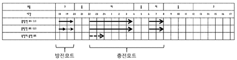
도3c를 참조하면, 차량에 탑재된 배터리의 충전 상태(SOC)는 21kWh(70%)이고, 가정에 배치된 배터리의 충전 상태(SOC)는 9kWh(60%)이고, 가정에서의 시간당 전력 사용량은 3kWh이라고 가정한다. 사용자 또는 운전자는 충전 시작 시간을 18시(6pm), 충전 출발 시간은 14시(2pm), 다음 목적지까지의 거리(거리 자동 계산)는 5km(왕복 10km)이라고 가정한다. 여기서는, 방전 모드와 충전 모드가 시간대 별로 발생할 수 있으며, 차량 내 배터리에서 방전 또는 차량 내 배터리로 충전이 수행되는 것(실선)과 가정 내 배터리에서 방전 또는 가정 내 배터리로 충전되는 것(점선)을 설명한다.Referring to FIG. 3C, the state of charge (SOC) of the battery mounted on the vehicle is 21 kWh (70%), the state of charge (SOC) of the battery disposed in the home is 9 kWh (60% Is assumed to be 3 kWh. The user or the driver assumes that the charging start time is 18:00 (6pm), the charging start time is 14:00 (2pm), and the distance to the next destination (automatic distance calculation) is 5km (10km round trip). Here, the discharge mode and the charge mode can be generated in each time zone, and the discharge from the battery in the vehicle or charging from the battery in the vehicle (solid line) and the charging from the battery in the home or the battery in the home Explain.
사용자 또는 운전자가 설정하는 충전 스케줄 모드가 방전 모드인 경우, 차량에 탑재된 배터리의 방전모드 최소요구 잔량을 20%(6kWh)로 설정하면, 전기 요율이 높은 시간대(18:00~20:00, 6pm~8pm)에 6kWh를 방전을 하고 전기 요율이 낮은 시간대(22:00~04:00 (10pm~4am), 06:00~08:00)에 설정된 방법(도3a 및 도3b의 충전 모드 참조)로 차량을 충전할 수 있다.When the charge schedule mode set by the user or the driver is the discharge mode and the minimum required residual amount of the battery mounted on the vehicle is set to 20% (6 kWh), the time period (18:00 to 20:00, 6 pm to 8 pm) and discharging at 6 kWh, and a method set at a time (22:00 to 04:00 (10 pm to 4 am), 06:00 to 08:00) in which the electric rate is low ) To charge the vehicle.
차량에 탑재된 배터리의 방전모드 최소요구 잔량을 60%(18kWh)로 설정하면, 전기 요율이 높은 시간대(18:00~20:00, 6pm~8pm)에 차량의 배터리에서 10%(3kWh), 가정에 배치된 배터리에서 3kWh를 방전하고 전기 요율이 낮은 시간대(22:00~04:00, 06:00~08:00)에 설정된 도3a 및 도3b에서 설명한 충전 모드로 차량을 충전할 수 있다.If the minimum required residual capacity of the battery mounted on the vehicle is set to 60% (18 kWh), the battery of the vehicle will be charged 10% (3 kWh) in the time period with high electricity rate (18:00 - 20:00, 6 pm - 8 pm) It is possible to discharge 3 kWh from the battery disposed in the home and charge the vehicle in the charging mode described in Fig. 3A and Fig. 3B set in the time zone (22: 00 ~ 04: 00, 06: 00 ~ 08: 00) .
가정에 배치된 배터리를 충전하기 위해, 배터리에 전력을 저장하는 방식으로 설정된 모드(예, 도3a 및 도3b의 충전 모드 참조)를 수행할 수 있다. 또한, 전기 요율이 낮은 시간대(22:00~04:00 (10pm~4am), 06:00~08)에 가정에 배치된 배터리의 완충 부족분 6kWh을 추가로 충전할 수 있다. 실시예에 따라, 전기 요율이 높은 시간대 계통에 전력 판매가 가능할 수 있다.In order to charge the battery disposed in the home, a mode set in a manner of storing power in the battery (e.g., refer to the charging mode of FIGS. 3A and 3B) can be performed. In addition, it is possible to additionally charge 6kWh of the battery shortage of the battery arranged in the home in the time period (22:00 to 04:00 (10 pm to 4 am), 06:00 to 08) in which the electric rate is low. According to the embodiment, it is possible to sell electric power in a time zone system having a high electric rate.
도4는 차량의 충방전 제어 방법을 설명한다.4 illustrates a charge / discharge control method for a vehicle.
도시된 바와 같이, 차량의 충방전 제어 방법은 제1전력 신호의 요금에 대응하여 제1전력 신호를 수신하여 배터리를 충전하는 단계(42), 및 배터리의 충전 잔량이 기 설정된 레벨 이상이면 요금에 대응하여 배터리에 저장된 에너지를 제2전력 신호로 송출하는 단계(44)를 포함할 수 있다. 도시되지 않았지만, 배터리를 충전하는 단계(42)는 제1전력 신호를 직류 전원으로 변환하는 단계, 및 직류 전원을 배터리에 축적하는 단계를 포함할 수 있다. 여기서, 전력선 통신을 통해 전달되는 제1전력 신호는 교류 전원일 수 있고, 배터리에는 직류 전원이 저장될 수 있다. 한편, 배터리를 충전하는 단계(42)는 요금과 배터리의 충전 목표량에 따라 수행될 수 있다.As shown in the figure, a charging / discharging control method of a vehicle includes a step (42) of receiving a first power signal in response to a charge of a first power signal to charge a battery, And transmitting (44) the energy stored in the battery correspondingly to the second power signal. Although not shown, step 42 of charging the battery may include converting the first power signal to DC power, and accumulating the DC power in the battery. Here, the first power signal transmitted through the power line communication may be AC power, and the DC power may be stored in the battery. On the other hand, step 42 of charging the battery may be performed according to the charge and the charge target amount of the battery.
한편, 제2전력 신호로 송출하는 단계(44)는 사용자의 입력 또는 기 설정된 제어 패턴에 대응하여 수행될 수 있다. 여기서, 제어 패턴은 시간대, 제1전력 신호에 대한 요금, 및 배터리를 충전하기 위한 옵션 중 적어도 하나에 따라 결정될 수 있다.On the other hand, the
예를 들면, 차량의 충방전은 공급되는 제1전력 신호의 요금이 시간대에 따라 변화될 수 있기 때문에, 요금이 낮은 경우 배터리를 충전하는 단계(42)를 수행하고, 요금이 높은 경우 제2전력 신호를 송출하는 단계(44)를 수행할 수 있다.For example, charging and discharging of the vehicle may be performed by charging the battery when the charge is low (step 42) because the charge of the supplied first power signal may change over time, A
보다 구체적으로, 충전하는 단계(42) 및 송출하는 단계(44) 모두 사용자의 입력 또는 기 설정된 제어 패턴에 대응하여 시간대별로 수행될 수 있다. 사용자 또는 운전자가 시간대별로 충전 또는 방전을 지정하거나 결정할 필요없이, 충전과 방전을 위한 몇가지 인자(factor)에 대한 선호도를 결정하면, 제어장치는 사용자의 선호도에 대응하는 제어 패턴을 생성할 수 있다.More specifically, both the charging
도5는 충전모드의 설정과 요금에 대응하는 충전 동작의 예를 설명한다.5 illustrates an example of the charging operation corresponding to the setting of the charging mode and the charge.
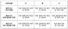
도시된 바와 같이, 충전 모드는 조건이 없는 경우, 최대 충전량을 기준으로 결정하는 경우, 최소 충전량을 기준으로 결정하는 경우 등이 있을 수 있다. 이러한 충전 모드는 집과 차량에 다르게 설정될 수도 있고, 동일하게 설정될 수도 있다. 한편, 실시예에 따라, 차량에 충전 모드를 설정하면 집에 배치된 배터리는 차량에 설정된 충전 모드에 연동할 수도 있다.As shown in the figure, the charging mode may be determined based on the maximum charging amount, on the basis of the minimum charging amount, on the condition that there is no condition, on the basis of the maximum charging amount, and the like. Such a charging mode may be set differently for the house and the vehicle, or may be set the same. On the other hand, according to the embodiment, when the charging mode is set to the vehicle, the battery disposed at the home may be linked to the charging mode set in the vehicle.
가정, 집에 공급되는 전력의 요율/요금은 다양할 수 있으나, 여기서는 '저', '중', '고'로 분류할 수 있다고 가정한다. 충전 모드는 사용자가 설정한 옵션을 바탕으로 기 설정된 전력의 요율/요금 또는 전력선 통신을 통해 전달되는 전력의 요율/요금에 따라 충전 패턴을 자동으로 결정할 수 있다. 간략하게는 전력의 요율/요금이 낮을 경우에는 차량 및 집에 포함된 배터리를 완충할 때까지 충전모드가 수행될 수 있다. 하지만, 전력의 요율이 '중' 또는 '고'에 해당하는 시간대인 경우에는 집 및 차량에 포함된 배터리는 선택적으로 충전모드가 수행될 수 있다.It is assumed that the rate of electricity supplied to the home and the house may vary, but here it can be classified as 'low', 'medium' and 'high'. The charging mode can automatically determine a charging pattern based on a preset rate / charge based on the option set by the user or a rate / rate of power transmitted through power line communication. Briefly, when the rate / charge of power is low, the charging mode can be performed until the battery contained in the vehicle and the house is fully charged. However, when the rate of power is in the middle or high, the battery included in the house and the vehicle may be selectively charged.
예를 들면, 만약 차량의 경우 현재 시간대의 요율이 높을 경우, 차량의 다음 사용 시간까지 요율이 낮은 시간대가 존재한다면 현재 충전 동작을 곧바로 수행할 필요가 없다. 하지만, 차량의 다음 사용 시간까지 요율이 낮은 시간대가 없다면 차량 내 배터리를 충전할 수 있다. 반면, 차량과 달리 집의 경우, 공급되는 전력의 요율이 높은 경우, 집에 배치되는 배터리를 충전할 필요가 없어질 수 있다.For example, if the rate of the current time zone is high for a vehicle, there is no need to perform the current charging operation immediately if there is a low rate zone until the next usage time of the vehicle. However, if the vehicle does not have a low rate until the next usage time, the battery in the vehicle can be charged. On the other hand, in the case of a house, unlike a vehicle, when the rate of supplied electric power is high, it may become unnecessary to charge the battery disposed in the house.
도6은 충전모드와 방전모드에 따른 전력이동의 예를 설명한다.6 illustrates an example of power transfer according to the charge mode and the discharge mode.
도시된 바와 같이, 전력 이동을 위한 충전 모드와 방전 모드는 가정에 공급되는 전력의 요금/요율에 대응하여 결정될 수 있다. 실시예에 따라 차량은 충전 모드와 방전 모드 중 하나를 선택적으로 수행하거나, 충전 모드와 방전 모드를 동시에 수행할 수도 있다. 충전 모드와 방전 모드를 동시에 수행할 수 있는 가에 따라 충전구의 수 및 충전 장치의 내부 설계가 달라질 수 있다.As shown, the charging mode and the discharging mode for power transfer can be determined corresponding to the charge / rate of power supplied to the home. According to the embodiment, the vehicle may selectively perform one of the charge mode and the discharge mode, or may perform the charge mode and the discharge mode at the same time. The number of charging ports and the internal design of the charging device may vary depending on whether the charging mode and the discharging mode can be performed at the same time.
예를 들어, 가정에 공급되는 전력의 요금/요율이 낮은 경우, 차량은 내부에 포함된 배터리에 저장된 전기 에너지를 송출할 필요가 없다. 이유는 가정에서도 저렴한 요금의 전력을 충전할 수 있기 때문이다.For example, if the rate / rate of power supplied to the home is low, the vehicle does not need to deliver electrical energy stored in the battery contained therein. The reason is that it is possible to charge a low-priced power at home.
반면, 가정에 공급되는 전력의 요금/요율이 높은 경우에는 차량의 운행 여부와 충전 가능한 시간 여부에 따라 차량 내부에 포함된 배터리에 저장되어 있는 전기 에너지를 가정으로 송출할 수도 있다. 이 경우, 가정에서는 보다 저렴한 전력을 이용할 수 있으며, 전력의 요금/요율이 낮아지면 차량 내부의 배터리를 충전할 수 있다.On the other hand, when the charge / rate of electric power supplied to the home is high, the electric energy stored in the battery included in the vehicle can be transmitted to the home depending on whether the vehicle is operated or not. In this case, more inexpensive power can be used at home, and the battery inside the vehicle can be charged if the charge / rate of electricity is lowered.
전술한 실시예를 통해, 종래에 스마트 그리드용 전기자동차의 양방향 전력 공급 시 개발자 중심의 충전 시스템으로 구현되어 있어 사용자에 대한 편의성이 고려되어 있지 않은 불편함을 극복하고, 스마트폰이나 가정내 PC, 월패드, 차량내 AVN 등을 통해 간단한 입력만으로 전력의 효율적인 관리가 가능할 수 있다.The above-described embodiments have overcome the inconvenience that convenience for the user is not considered due to being implemented as a developer-oriented charging system in the bidirectional power supply of an electric vehicle for a smart grid in the past, It is possible to manage the power efficiently by simple input through the wall pad, AVN in the vehicle, and the like.
또한, 실시예를 통해, 종래에 전기 요율 분석의 구체적인 방법 및 정보 수신 방법이 없거나 사용자가 직접 전기 요율 로우 데이터를 입력하는 방식으로 사용 편의성이 고려되어 있지 않은 불편함을 극복하고, 전기자동차 및 가정에서 사용되는 전력을 효율적으로 관리함으로써 전기요금 절감 가능할 수 있다.In addition, through the embodiments, it is possible to overcome the inconvenience that the convenience of use is not considered in the conventional method of analyzing the electric power rate and the method of receiving the information, or the method in which the user directly inputs the electric rate low data, It is possible to reduce the electricity bill by efficiently managing the electric power used in the power line.
상술한 실시예에 따른 방법은 컴퓨터에서 실행되기 위한 프로그램으로 제작되어 컴퓨터가 읽을 수 있는 기록 매체에 저장될 수 있으며, 컴퓨터가 읽을 수 있는 기록 매체의 예로는 ROM, RAM, CD-ROM, 자기 테이프, 플로피디스크, 광 데이터 저장장치 등이 포함된다.The method according to the above-described embodiments may be implemented as a program to be executed by a computer and stored in a computer-readable recording medium. Examples of the computer-readable recording medium include a ROM, a RAM, a CD- , Floppy disks, optical data storage devices, and the like.
컴퓨터가 읽을 수 있는 기록 매체는 네트워크로 연결된 컴퓨터 시스템에 분산되어, 분산방식으로 컴퓨터가 읽을 수 있는 코드가 저장되고 실행될 수 있다. 그리고, 상술한 방법을 구현하기 위한 기능적인(function) 프로그램, 코드 및 코드 세그먼트들은 실시예가 속하는 기술분야의 프로그래머들에 의해 용이하게 추론될 수 있다.The computer readable recording medium may be distributed over a networked computer system so that computer readable code can be stored and executed in a distributed manner. And, functional program, code, and code segments for implementing the above-described method can be easily inferred by programmers in the technical field to which the embodiment belongs.
본 발명은 본 발명의 정신 및 필수적 특징을 벗어나지 않는 범위에서 다른 특정한 형태로 구체화될 수 있음은 당업자에게 자명하다.It will be apparent to those skilled in the art that the present invention may be embodied in other specific forms without departing from the spirit or essential characteristics thereof.
따라서, 상기의 상세한 설명은 모든 면에서 제한적으로 해석되어서는 아니되고 예시적인 것으로 고려되어야 한다. 본 발명의 범위는 첨부된 청구항의 합리적 해석에 의해 결정되어야 하고, 본 발명의 등가적 범위 내에서의 모든 변경은 본 발명의 범위에 포함된다.Accordingly, the above description should not be construed in a limiting sense in all respects and should be considered illustrative. The scope of the present invention should be determined by rational interpretation of the appended claims, and all changes within the scope of equivalents of the present invention are included in the scope of the present invention.
48: 발전소, 전력공급시설물
20: 가정, 주택
30: 전기자동차
40: 사무용 빌딩
12: 전력선 통신
32: 충방전기
26: 분배기48: power plant, power supply facility 20: home, housing
30: Electric vehicle 40: Office building
12: Power line communication 32: Charger / discharger
26: Dispenser
Claims (27)
상기 제1전력 신호가 직류 변환되어 전달된 전기 에너지를 저장하는 배터리; 및
사용자의 입력 또는 기 설정된 제어 패턴에 대응하여 상기 충방전 장치를 제어하는 충방전 제어 장치
를 포함하는, 차량용 전력 장치.A charging / discharging device capable of selectively performing a charging function for receiving and transmitting the first power signal and a discharging function for transmitting the second power signal;
A battery for storing electric energy transferred by DC conversion of the first power signal; And
A charge / discharge control device for controlling the charge / discharge device corresponding to a user's input or a predetermined control pattern,
And a second power supply.
상기 제1전력 신호는 교류 전력 신호이고, 상기 제2전력 신호는 직류 전력 신호인, 차량용 전력 장치.The method according to claim 1,
Wherein the first power signal is an AC power signal and the second power signal is a DC power signal.
상기 충방전 장치는 차량 내 상기 제1전력 신호 및 상기 제2전력 신호를 송수신하기 위한 하나의 충전구와 연결되는, 차량용 전력 장치.The method according to claim 1,
Wherein the charge / discharge device is connected to one charging port for transmitting / receiving the first power signal and the second power signal in the vehicle.
상기 충방전 장치는 차량 내 상기 제1전력 신호를 수신하기 위한 제1충전구 및 상기 제2전력 신호를 송신하기 위한 제2충전구와 연결되는, 차량용 전력 장치.The method according to claim 1,
Wherein the charge / discharge device is connected to a first charging port for receiving the first power signal in the vehicle and a second charging port for transmitting the second power signal.
상기 배터리의 충전상태 및 온도를 모니터링하여 상기 충방전 제어 장치에 보고하는 배터리 관리장치
를 더 포함하는, 차량용 전력 장치.The method according to claim 1,
A battery management device for monitoring the charged state and temperature of the battery and reporting the monitored state to the charge /
Further comprising: a power supply for powering the vehicle.
상기 제어 패턴은 시간대, 상기 제1전력 신호에 대한 요금, 및 상기 배터리를 충전하기 위한 옵션 중 적어도 하나에 따라 결정되는, 차량용 전력 장치.The method according to claim 1,
Wherein the control pattern is determined according to at least one of a time zone, a charge for the first power signal, and an option for charging the battery.
상기 제1전력 신호에 대한 요금은 상기 시간대에 따라 변화될 수 있으며,
상기 충방전 장치는
상기 요금이 낮은 경우, 상기 충전 기능을 수행하고,
상기 요금이 높은 경우, 상기 방전기능을 수행하는, 차량용 전력 장치.The method according to claim 6,
The charge for the first power signal may vary according to the time zone,
The charge /
Performs the charging function when the charge is low,
And performs the discharging function when the charge is high.
상기 방전기능은 상기 배터리가 기 설정된 충전 최소요구 잔량 이상으로 충전되어 있는 경우에만 수행될 수 있는, 차량용 전력 장치.8. The method of claim 7,
Wherein the discharging function can be performed only when the battery is charged to a predetermined minimum charging remaining capacity.
상기 충전기능은 상기 요금과 상기 배터리의 충전 목표량에 따라 수행되는, 차량용 전력 장치.8. The method of claim 7,
Wherein the charging function is performed in accordance with the charge and the charging target amount of the battery.
상기 충방전 장치는 상기 제1전력 신호가 공급되지 않는 경우, 상기 제1전력 신호와 구별되는 제3전력 신호를 수신하는, 차량용 전력 장치.The method according to claim 1,
Wherein the charge / discharge device receives a third power signal that is different from the first power signal when the first power signal is not supplied.
상기 제3전력 신호는 직류 전력 신호인, 차량용 전력 장치.11. The method of claim 10,
And the third power signal is a DC power signal.
상기 사용자의 입력은 차량에 탑재된 오디오-비디오-내비게이션 장치를 통해 전달되거나, 기 설정된 제어 패턴은 상기 오디오-비디오-내비게이션 장치와 연동하는 저장 장치에 저장되는, 차량용 전력 장치.The method according to claim 1,
Wherein the input of the user is transmitted via an audio-video-navigation device mounted on the vehicle, or a predetermined control pattern is stored in a storage device associated with the audio-video-navigation device.
상기 사용자의 입력 및 상기 제어 패턴의 설정은 상기 오디오-비디오-내비게이션 장치와 연동하는 무선통신장치를 통해 이루어질 수 있는, 차량용 전력 장치.13. The method of claim 12,
Wherein the input of the user and the setting of the control pattern can be made via a wireless communication device in association with the audio-video-navigation device.
상기 충방전 제어 장치는 상기 무선통신장치를 통해 상기 충전기능, 상기 방전기능, 상기 배터리 상태 중 적어도 하나에 대한 정보를 전달할 수 있는, 차량용 전력 장치.14. The method of claim 13,
Wherein the charge / discharge control device is capable of transmitting information on at least one of the charging function, the discharging function, and the battery state via the wireless communication device.
상기 배터리의 충전 잔량이 기 설정된 레벨 이상이면 상기 요금에 대응하여 상기 배터리에 저장된 에너지를 제2전력 신호로 송출하는 단계
를 포함하는, 차량의 충방전 제어 방법.Receiving the first power signal in response to the charge of the first power signal to charge the battery; And
Transmitting the energy stored in the battery as a second power signal in response to the charge if the charge remaining amount of the battery is equal to or higher than a predetermined level
And controlling the charge / discharge of the vehicle.
상기 배터리를 충전하는 단계는
상기 제1전력 신호를 직류 전원으로 변환하는 단계; 및
상기 직류 전원을 배터리에 축적하는 단계를 포함하고,
상기 제1전력 신호는 교류 전원인, 차량의 충방전 제어 방법.16. The method of claim 15,
The step of charging the battery
Converting the first power signal to a DC power source; And
And accumulating the DC power in a battery,
Wherein the first power signal is an AC power source.
상기 제2전력 신호로 송출하는 단계는 사용자의 입력 또는 기 설정된 제어 패턴에 대응하여 수행되는, 차량의 충방전 제어 방법.16. The method of claim 15,
Wherein the step of transmitting the second power signal is performed in response to a user's input or a predetermined control pattern.
상기 제어 패턴은 시간대, 상기 제1전력 신호에 대한 요금, 및 상기 배터리를 충전하기 위한 옵션 중 적어도 하나에 따라 결정되는, 차량의 충방전 제어 방법.18. The method of claim 17,
Wherein the control pattern is determined according to at least one of a time zone, a charge for the first power signal, and an option for charging the battery.
상기 제1전력 신호의 요금은 상기 시간대에 따라 변화될 수 있으며,
상기 요금이 낮은 경우, 상기 배터리를 충전하는 단계를 수행하고,
상기 요금이 높은 경우, 상기 제2전력 신호를 송출하는 단계를 수행하는, 차량의 충방전 제어 방법.16. The method of claim 15,
The rate of the first power signal may vary according to the time zone,
If the charge is low, charging the battery,
And if the charge is high, transmitting the second power signal.
상기 배터리를 충전하는 단계는 상기 요금과 상기 배터리의 충전 목표량에 따라 수행되는, 차량의 충방전 제어 방법.16. The method of claim 15,
Wherein the step of charging the battery is performed in accordance with the charge and the charge target amount of the battery.
상기 분배기로부터 전달되는 전기 에너지를 저장하는 배터리; 및
상기 배터리와 상기 차량 간 상기 전기 에너지를 송수신하기 위한 전력이동기
를 포함하는, 가정용 전력 관리 장치.A distributor connected to the power line communication network to supply a first power signal for charging the vehicle;
A battery for storing electric energy transferred from the distributor; And
A power mover for transmitting and receiving the electric energy between the battery and the vehicle,
And a power management unit for controlling the power management unit.
상기 전력이동기는 상기 차량의 요구에 의해 상기 배터리에 저장된 상기 전기 에너지를 송신하거나 상기 차량으로부터 상기 전기 에너지를 수신하는, 가정용 전력 관리 장치.23. The method of claim 22,
Wherein the power mover transmits the electric energy stored in the battery or receives the electric energy from the vehicle at the request of the vehicle.
상기 제1전력 신호의 요금에 대응하여 상기 배터리를 충전하며 상기 배터리의 충전 상태 및 온도를 모니터링할 수 있는 배터리 관리장치
를 더 포함하는, 가정용 전력 관리 장치.23. The method of claim 22,
And a battery management device for charging the battery in response to the charge of the first power signal and monitoring a charge state and a temperature of the battery,
Further comprising: a power control unit for controlling the power supply unit.
상기 분배기는 가정에서 사용하는 가전제품에 제4전력 신호를 공급하며,
상기 제1전력 신호 및 상기 제2전력 신호에 대한 과금 정보를 결정하는, 가정용 전력 관리 장치.23. The method of claim 22,
The distributor supplies a fourth power signal to household appliances used in the home,
And determines charging information for the first power signal and the second power signal.
상기 전력이동기는 상기 차량에 공급되는 상기 제1전력 신호를 전달하고 상기 차량으로부터 제2전력 신호를 수신하기 위한 하나의 충전구와 연결되는, 가정용 전력 관리 장치.23. The method of claim 22,
Wherein the power mover is coupled to one charging port for transferring the first power signal supplied to the vehicle and for receiving a second power signal from the vehicle.
상기 전력이동기는 상기 차량에 공급되는 상기 제1전력 신호를 전달하기 위한 제1충전구 및 상기 차량으로부터 제2전력 신호를 송신하기 위한 제2충전구와 연결되는, 가정용 전력 관리 장치.23. The method of claim 22,
Wherein the power mover is connected to a first charging port for transferring the first power signal supplied to the vehicle and a second charging port for transmitting a second power signal from the vehicle.
Priority Applications (3)
| Application Number | Priority Date | Filing Date | Title |
|---|---|---|---|
| KR1020170055393A KR20180121105A (en) | 2017-04-28 | 2017-04-28 | Apparatus and method for charging and discharging electric vehcile under smart grid environment |
| US15/833,908 US11413984B2 (en) | 2017-04-28 | 2017-12-06 | Apparatus and method for charging and discharging electric vehicle under smart grid environment |
| CN201711447834.7A CN108808760A (en) | 2017-04-28 | 2017-12-27 | For under intelligent grid environment to the device and method of electric vehicle charging and electric discharge |
Applications Claiming Priority (1)
| Application Number | Priority Date | Filing Date | Title |
|---|---|---|---|
| KR1020170055393A KR20180121105A (en) | 2017-04-28 | 2017-04-28 | Apparatus and method for charging and discharging electric vehcile under smart grid environment |
Publications (1)
| Publication Number | Publication Date |
|---|---|
| KR20180121105A true KR20180121105A (en) | 2018-11-07 |
Family
ID=63915903
Family Applications (1)
| Application Number | Title | Priority Date | Filing Date |
|---|---|---|---|
| KR1020170055393A KR20180121105A (en) | 2017-04-28 | 2017-04-28 | Apparatus and method for charging and discharging electric vehcile under smart grid environment |
Country Status (3)
| Country | Link |
|---|---|
| US (1) | US11413984B2 (en) |
| KR (1) | KR20180121105A (en) |
| CN (1) | CN108808760A (en) |
Cited By (2)
| Publication number | Priority date | Publication date | Assignee | Title |
|---|---|---|---|---|
| KR20200087294A (en) * | 2018-12-26 | 2020-07-21 | 주식회사 파워큐브코리아 | V2g system using electric vehicle |
| WO2023016655A1 (en) * | 2021-08-13 | 2023-02-16 | Hitachi Energy Switzerland Ag | Controlling and scheduling of charging of electrical vehicles and related systems and methods |
Families Citing this family (22)
| Publication number | Priority date | Publication date | Assignee | Title |
|---|---|---|---|---|
| JP6724343B2 (en) | 2015-11-17 | 2020-07-15 | オムロン株式会社 | Reservation management device, reservation management system, and reservation management method |
| JP6766343B2 (en) * | 2015-11-17 | 2020-10-14 | オムロン株式会社 | Battery reservation device |
| JP6582909B2 (en) | 2015-11-17 | 2019-10-02 | オムロン株式会社 | Battery reservation device and battery reservation method |
| JP6597218B2 (en) | 2015-11-17 | 2019-10-30 | オムロン株式会社 | Battery reservation device and battery reservation method |
| JP6551424B2 (en) * | 2017-01-10 | 2019-07-31 | トヨタ自動車株式会社 | Charge control device and charge control method |
| DE102017210747A1 (en) * | 2017-06-27 | 2018-12-27 | Bayerische Motoren Werke Aktiengesellschaft | A method for preheating a battery of an electrically operated motor vehicle and charging device |
| JP7017476B2 (en) * | 2018-06-21 | 2022-02-08 | トヨタ自動車株式会社 | Information providing equipment, information providing system, information providing method, and program |
| CN109474036A (en) * | 2018-11-23 | 2019-03-15 | 重庆长安新能源汽车科技有限公司 | The charge-discharge connecting device of integrated AC charging and electric discharge |
| DE102018220311A1 (en) * | 2018-11-27 | 2020-05-28 | Audi Ag | Method for providing and performing services in a parking garage, as well as a service management system and a parking garage |
| FR3090516A1 (en) * | 2018-12-21 | 2020-06-26 | Psa Automobiles Sa | Recharging the battery of an electrified motor vehicle |
| JP7212557B2 (en) * | 2019-03-15 | 2023-01-25 | 本田技研工業株式会社 | power management device |
| JP2020156194A (en) * | 2019-03-20 | 2020-09-24 | 本田技研工業株式会社 | Control apparatus and program |
| US11218011B2 (en) * | 2019-04-26 | 2022-01-04 | StoreDot Ltd. | Fast charging and power boosting lithium-ion batteries |
| US10587309B1 (en) * | 2019-05-13 | 2020-03-10 | Robert Bosch Gmbh | Intermittent actuators powered by twisted-wire connection |
| JP7116015B2 (en) * | 2019-06-12 | 2022-08-09 | 本田技研工業株式会社 | Emergency power supply system, emergency power supply method, and program |
| US11515587B2 (en) * | 2019-10-10 | 2022-11-29 | Robert Bosch Gmbh | Physics-based control of battery temperature |
| JP7310672B2 (en) * | 2020-03-23 | 2023-07-19 | トヨタ自動車株式会社 | Information presentation system |
| KR20220023603A (en) * | 2020-08-21 | 2022-03-02 | 삼성전자주식회사 | Portable device communicating with charger and operating method thereof |
| US11845353B2 (en) * | 2020-12-04 | 2023-12-19 | Total Se | Methods and systems for optimal pricing and charging control of a plug-in electric vehicle charging station |
| CN114614515A (en) * | 2020-12-08 | 2022-06-10 | 宁德时代新能源科技股份有限公司 | Charging and discharging device and power transmission method thereof |
| CN114274827A (en) * | 2021-12-06 | 2022-04-05 | 上海电享信息科技有限公司 | Charging station control system combining cloud service and local control |
| US20230280706A1 (en) * | 2022-03-02 | 2023-09-07 | Toyota Motor North America, Inc. | Event energy muting and management |
Family Cites Families (41)
| Publication number | Priority date | Publication date | Assignee | Title |
|---|---|---|---|---|
| JP2000013924A (en) * | 1998-06-22 | 2000-01-14 | System Soken:Kk | Connected electric automobile |
| JP3985390B2 (en) | 1999-06-17 | 2007-10-03 | 日産自動車株式会社 | Power management system |
| US20070282495A1 (en) * | 2006-05-11 | 2007-12-06 | University Of Delaware | System and method for assessing vehicle to grid (v2g) integration |
| WO2008141246A2 (en) * | 2007-05-09 | 2008-11-20 | Gridpoint, Inc. | Method and system for scheduling the discharge of distributed power storage devices and for levelizing dispatch participation |
| US20100017045A1 (en) * | 2007-11-30 | 2010-01-21 | Johnson Controls Technology Company | Electrical demand response using energy storage in vehicles and buildings |
| US8872379B2 (en) * | 2007-11-30 | 2014-10-28 | Johnson Controls Technology Company | Efficient usage, storage, and sharing of energy in buildings, vehicles, and equipment |
| US7928693B2 (en) * | 2008-03-13 | 2011-04-19 | International Business Machines Corporation | Plugin hybrid electric vehicle with V2G optimization system |
| JP4713623B2 (en) * | 2008-09-25 | 2011-06-29 | 株式会社日立製作所 | Charge / discharge management device |
| JP2010154646A (en) * | 2008-12-25 | 2010-07-08 | Omron Corp | Apparatus and method for controlling charge, and program |
| JP4737307B2 (en) * | 2009-02-16 | 2011-07-27 | 株式会社デンソー | Plug-in car charging status notification system |
| KR20110054135A (en) * | 2009-11-17 | 2011-05-25 | 현대자동차주식회사 | Soc band strategy for hev |
| JP5724053B2 (en) * | 2009-12-21 | 2015-05-27 | パナソニックIpマネジメント株式会社 | Electric vehicle power supply system |
| JP5552817B2 (en) * | 2010-01-25 | 2014-07-16 | ソニー株式会社 | Power management system, power management device, power management method, power storage device, and electric vehicle |
| US9043038B2 (en) * | 2010-02-18 | 2015-05-26 | University Of Delaware | Aggregation server for grid-integrated vehicles |
| WO2011127446A2 (en) * | 2010-04-09 | 2011-10-13 | Aerovironment, Inc. | Portable charging cable with in-line controller |
| KR101132948B1 (en) * | 2010-05-13 | 2012-04-05 | 엘에스산전 주식회사 | System, Apparatus and Method for Charge and Discharge Control of Electric Vehicle |
| CN103052529B (en) * | 2010-10-05 | 2015-09-23 | 三菱电机株式会社 | Battery charge controller |
| KR101262459B1 (en) * | 2010-10-12 | 2013-05-08 | 기아자동차주식회사 | Telematics unit for remote charging control and service providing method of the same |
| JP2012123637A (en) * | 2010-12-08 | 2012-06-28 | Sharp Corp | Charge controller, control method of charge controller, charge/discharge controller, control method of charge/discharge controller, control program, and recording medium |
| US8907811B2 (en) * | 2011-01-04 | 2014-12-09 | Greenwave Systems Pte. Ltd. | Multi-mode display |
| JP2012175791A (en) * | 2011-02-21 | 2012-09-10 | Denso Corp | Electric power supply system |
| CN102859783A (en) * | 2011-04-15 | 2013-01-02 | 松下电器产业株式会社 | Battery-history information management apparatus, battery-history information management method, battery-history information management system, and power storage apparatus |
| JP5644650B2 (en) * | 2011-04-18 | 2014-12-24 | 三菱電機株式会社 | Charging / discharging system and charging / discharging device between electric vehicle and house |
| TWI443505B (en) * | 2011-07-20 | 2014-07-01 | Delta Electronics Inc | Smart charging system for vehicles and method of operating the same |
| JP5672186B2 (en) * | 2011-07-24 | 2015-02-18 | 株式会社デンソー | Power supply system |
| JP5942993B2 (en) * | 2011-09-01 | 2016-06-29 | 日本電気株式会社 | Charge control system, charge control method and program |
| JP5234159B2 (en) * | 2011-10-31 | 2013-07-10 | トヨタ自動車株式会社 | A vehicle including a power storage unit capable of discharging (power feeding) to an external load, a discharge system including the vehicle and a power cable, a discharge control method for the power storage unit, and a device outside the vehicle used in the discharge system. |
| EP2783899B1 (en) * | 2011-11-21 | 2019-05-15 | Toyota Jidosha Kabushiki Kaisha | Charging system and charging reservation method |
| JP5967516B2 (en) * | 2011-11-22 | 2016-08-10 | パナソニックIpマネジメント株式会社 | Power management apparatus, power management program, and power distribution system |
| CN102624015A (en) * | 2012-01-12 | 2012-08-01 | 清华大学 | Control device for interchanging electric energy of electric vehicle and electric energy of residence |
| EP2858211B1 (en) * | 2012-05-29 | 2017-11-22 | Panasonic Intellectual Property Management Co., Ltd. | Apparatus, system, and method for detecting unauthorized connections of a charge/discharge device |
| KR20130138954A (en) * | 2012-06-12 | 2013-12-20 | 현대모비스 주식회사 | Two-way power supply apparatus of electric vehicle for smart grid and two-way power supply method using the same |
| KR20140068384A (en) | 2012-11-28 | 2014-06-09 | 한국전기연구원 | Apartment smart power management system and method using electric vehicle |
| KR101488586B1 (en) * | 2013-03-04 | 2015-02-02 | 주식회사 엘지씨엔에스 | Method and system of dynamic charging |
| EP2842792A1 (en) * | 2013-08-27 | 2015-03-04 | Alpiq InTec AG | Method for recharging an accumulator of an electric vehicle |
| KR101610482B1 (en) * | 2014-07-28 | 2016-04-07 | 현대자동차주식회사 | Method and Apparatus for Stopping Charge Reservation and Charging Promptly Electric Vehicle |
| KR101601473B1 (en) * | 2014-08-25 | 2016-03-09 | 현대자동차주식회사 | Device and method for controlling battery SOC of hybrid vehicle |
| JP6582737B2 (en) * | 2015-08-25 | 2019-10-02 | 住友電気工業株式会社 | Charge / discharge control device and control program |
| US10011183B2 (en) * | 2016-03-09 | 2018-07-03 | Toyota Jidosha Kabushiki Kaisha | Optimized charging and discharging of a plug-in electric vehicle |
| US10411488B2 (en) * | 2016-05-02 | 2019-09-10 | Club Car, Llc | Onboard battery charging system |
| KR102322921B1 (en) * | 2017-02-22 | 2021-11-08 | 현대자동차주식회사 | Electric vehicle and control method thereof |
-
2017
- 2017-04-28 KR KR1020170055393A patent/KR20180121105A/en not_active Application Discontinuation
- 2017-12-06 US US15/833,908 patent/US11413984B2/en active Active
- 2017-12-27 CN CN201711447834.7A patent/CN108808760A/en active Pending
Cited By (2)
| Publication number | Priority date | Publication date | Assignee | Title |
|---|---|---|---|---|
| KR20200087294A (en) * | 2018-12-26 | 2020-07-21 | 주식회사 파워큐브코리아 | V2g system using electric vehicle |
| WO2023016655A1 (en) * | 2021-08-13 | 2023-02-16 | Hitachi Energy Switzerland Ag | Controlling and scheduling of charging of electrical vehicles and related systems and methods |
Also Published As
| Publication number | Publication date |
|---|---|
| US11413984B2 (en) | 2022-08-16 |
| CN108808760A (en) | 2018-11-13 |
| US20180312072A1 (en) | 2018-11-01 |
Similar Documents
| Publication | Publication Date | Title |
|---|---|---|
| KR20180121105A (en) | Apparatus and method for charging and discharging electric vehcile under smart grid environment | |
| US20190061535A1 (en) | Electric vehicle power management systems | |
| CN101436689B (en) | Power grid load management for plug-in vehicles | |
| US9428067B2 (en) | Vehicle running management system under renewable energy | |
| CN101257218B (en) | System and method for interactive battery charger for electric vehicle | |
| US10647209B2 (en) | Managing and optimizing energy supply from grid and renewable source with electric vehicle supply equipment | |
| US8664915B2 (en) | Plug-in vehicle | |
| KR101189852B1 (en) | System and method for managing charger of Electric vehicle using a network of AMI system | |
| JP6015038B2 (en) | Vehicle and vehicle control method | |
| KR101505744B1 (en) | Intelligent multi-charging system | |
| US11400827B2 (en) | Power network management | |
| JP2023508135A (en) | Electric vehicle charger power supply method | |
| Vermesan et al. | Smart, connected and mobile: Architecting future electric mobility ecosystems | |
| US20230147695A1 (en) | Electric Vehicle Charging System | |
| Zidan et al. | Design and control of V2G | |
| KR101493691B1 (en) | Electric charging system and control method thereof, and control method of apparatus for charging | |
| JP2012085406A (en) | On-vehicle charge/discharge apparatus | |
| KR20150089171A (en) | Voltage-meter of charging for Electric Vehicle | |
| US20230256855A1 (en) | Electrified vehicle fleet charging control system and method | |
| US11801767B2 (en) | Control of vehicle and home energy storage systems | |
| US20230406147A1 (en) | Bidirectional electric vehicle charging system | |
| US20240042885A1 (en) | Power system, control device, and power system control method | |
| US20230129230A1 (en) | Energy management | |
| Vasconcelos | Electric vehicle smart charging | |
| KR20230116211A (en) | Charging communication control device for electric vehicle and charging control system for electric vehicle |
Legal Events
| Date | Code | Title | Description |
|---|---|---|---|
| A201 | Request for examination | ||
| E902 | Notification of reason for refusal | ||
| E601 | Decision to refuse application |