KR20180117455A - Composite laminated insulation and structural membrane, and method for manufacturing the same - Google Patents
Composite laminated insulation and structural membrane, and method for manufacturing the same Download PDFInfo
- Publication number
- KR20180117455A KR20180117455A KR1020170050593A KR20170050593A KR20180117455A KR 20180117455 A KR20180117455 A KR 20180117455A KR 1020170050593 A KR1020170050593 A KR 1020170050593A KR 20170050593 A KR20170050593 A KR 20170050593A KR 20180117455 A KR20180117455 A KR 20180117455A
- Authority
- KR
- South Korea
- Prior art keywords
- heat insulating
- elastomer
- frame
- plate
- insulating material
- Prior art date
Links
- 238000009413 insulation Methods 0.000 title claims abstract description 104
- 239000002131 composite material Substances 0.000 title claims abstract description 78
- 238000000034 method Methods 0.000 title claims abstract description 40
- 238000004519 manufacturing process Methods 0.000 title claims abstract description 20
- 239000012528 membrane Substances 0.000 title 1
- 229920001971 elastomer Polymers 0.000 claims abstract description 145
- 239000000806 elastomer Substances 0.000 claims abstract description 145
- 239000012774 insulation material Substances 0.000 claims abstract description 71
- 239000011810 insulating material Substances 0.000 claims description 112
- 125000006850 spacer group Chemical group 0.000 claims description 16
- 239000011800 void material Substances 0.000 claims description 14
- 239000000463 material Substances 0.000 abstract description 35
- 238000010276 construction Methods 0.000 abstract description 16
- 239000012212 insulator Substances 0.000 abstract description 14
- 239000007788 liquid Substances 0.000 abstract description 10
- 230000001788 irregular Effects 0.000 abstract description 3
- 239000007769 metal material Substances 0.000 abstract description 3
- 239000002184 metal Substances 0.000 description 34
- 229910052751 metal Inorganic materials 0.000 description 34
- 238000013461 design Methods 0.000 description 17
- 239000006260 foam Substances 0.000 description 15
- 229910000831 Steel Inorganic materials 0.000 description 14
- 239000010959 steel Substances 0.000 description 14
- 239000004814 polyurethane Substances 0.000 description 10
- 238000012423 maintenance Methods 0.000 description 9
- 229920002635 polyurethane Polymers 0.000 description 8
- 230000035939 shock Effects 0.000 description 8
- 239000007787 solid Substances 0.000 description 7
- XEEYBQQBJWHFJM-UHFFFAOYSA-N Iron Chemical compound [Fe] XEEYBQQBJWHFJM-UHFFFAOYSA-N 0.000 description 6
- 238000010521 absorption reaction Methods 0.000 description 6
- 239000004964 aerogel Substances 0.000 description 6
- 238000005507 spraying Methods 0.000 description 6
- 230000000694 effects Effects 0.000 description 5
- 238000002347 injection Methods 0.000 description 5
- 239000007924 injection Substances 0.000 description 5
- 238000009434 installation Methods 0.000 description 5
- 239000000203 mixture Substances 0.000 description 5
- 239000000295 fuel oil Substances 0.000 description 4
- 238000010438 heat treatment Methods 0.000 description 4
- 239000010762 marine fuel oil Substances 0.000 description 4
- 239000000126 substance Substances 0.000 description 4
- 241000183024 Populus tremula Species 0.000 description 3
- 238000005452 bending Methods 0.000 description 3
- 239000004567 concrete Substances 0.000 description 3
- 238000010586 diagram Methods 0.000 description 3
- 238000012986 modification Methods 0.000 description 3
- 230000004048 modification Effects 0.000 description 3
- 229920002396 Polyurea Polymers 0.000 description 2
- 239000000969 carrier Substances 0.000 description 2
- 239000011248 coating agent Substances 0.000 description 2
- 238000000576 coating method Methods 0.000 description 2
- 230000006835 compression Effects 0.000 description 2
- 238000007906 compression Methods 0.000 description 2
- 238000007796 conventional method Methods 0.000 description 2
- 238000005336 cracking Methods 0.000 description 2
- 239000000446 fuel Substances 0.000 description 2
- 229920003023 plastic Polymers 0.000 description 2
- 239000004033 plastic Substances 0.000 description 2
- 239000002861 polymer material Substances 0.000 description 2
- 238000005057 refrigeration Methods 0.000 description 2
- 241000894007 species Species 0.000 description 2
- 238000012360 testing method Methods 0.000 description 2
- 238000012546 transfer Methods 0.000 description 2
- 238000003466 welding Methods 0.000 description 2
- 239000002023 wood Substances 0.000 description 2
- 239000004743 Polypropylene Substances 0.000 description 1
- 229920005830 Polyurethane Foam Polymers 0.000 description 1
- VYPSYNLAJGMNEJ-UHFFFAOYSA-N Silicium dioxide Chemical compound O=[Si]=O VYPSYNLAJGMNEJ-UHFFFAOYSA-N 0.000 description 1
- 239000000443 aerosol Substances 0.000 description 1
- 230000004075 alteration Effects 0.000 description 1
- 230000003466 anti-cipated effect Effects 0.000 description 1
- 239000004035 construction material Substances 0.000 description 1
- 230000008602 contraction Effects 0.000 description 1
- 239000002178 crystalline material Substances 0.000 description 1
- 230000002542 deteriorative effect Effects 0.000 description 1
- 239000000835 fiber Substances 0.000 description 1
- 239000004088 foaming agent Substances 0.000 description 1
- 229910021485 fumed silica Inorganic materials 0.000 description 1
- 229910052742 iron Inorganic materials 0.000 description 1
- 238000005304 joining Methods 0.000 description 1
- 239000011490 mineral wool Substances 0.000 description 1
- 229920000728 polyester Polymers 0.000 description 1
- -1 polypropylene Polymers 0.000 description 1
- 229920001155 polypropylene Polymers 0.000 description 1
- 229920003225 polyurethane elastomer Polymers 0.000 description 1
- 239000011496 polyurethane foam Substances 0.000 description 1
- 229920005989 resin Polymers 0.000 description 1
- 239000011347 resin Substances 0.000 description 1
- 238000006467 substitution reaction Methods 0.000 description 1
- 229920003002 synthetic resin Polymers 0.000 description 1
- 239000000057 synthetic resin Substances 0.000 description 1
Images


Classifications
-
- F—MECHANICAL ENGINEERING; LIGHTING; HEATING; WEAPONS; BLASTING
- F16—ENGINEERING ELEMENTS AND UNITS; GENERAL MEASURES FOR PRODUCING AND MAINTAINING EFFECTIVE FUNCTIONING OF MACHINES OR INSTALLATIONS; THERMAL INSULATION IN GENERAL
- F16L—PIPES; JOINTS OR FITTINGS FOR PIPES; SUPPORTS FOR PIPES, CABLES OR PROTECTIVE TUBING; MEANS FOR THERMAL INSULATION IN GENERAL
- F16L59/00—Thermal insulation in general
- F16L59/02—Shape or form of insulating materials, with or without coverings integral with the insulating materials
-
- B—PERFORMING OPERATIONS; TRANSPORTING
- B63—SHIPS OR OTHER WATERBORNE VESSELS; RELATED EQUIPMENT
- B63B—SHIPS OR OTHER WATERBORNE VESSELS; EQUIPMENT FOR SHIPPING
- B63B25/00—Load-accommodating arrangements, e.g. stowing, trimming; Vessels characterised thereby
- B63B25/02—Load-accommodating arrangements, e.g. stowing, trimming; Vessels characterised thereby for bulk goods
- B63B25/08—Load-accommodating arrangements, e.g. stowing, trimming; Vessels characterised thereby for bulk goods fluid
- B63B25/12—Load-accommodating arrangements, e.g. stowing, trimming; Vessels characterised thereby for bulk goods fluid closed
- B63B25/14—Load-accommodating arrangements, e.g. stowing, trimming; Vessels characterised thereby for bulk goods fluid closed pressurised
-
- B—PERFORMING OPERATIONS; TRANSPORTING
- B63—SHIPS OR OTHER WATERBORNE VESSELS; RELATED EQUIPMENT
- B63B—SHIPS OR OTHER WATERBORNE VESSELS; EQUIPMENT FOR SHIPPING
- B63B3/00—Hulls characterised by their structure or component parts
- B63B3/14—Hull parts
- B63B3/68—Panellings; Linings, e.g. for insulating purposes
-
- E—FIXED CONSTRUCTIONS
- E04—BUILDING
- E04B—GENERAL BUILDING CONSTRUCTIONS; WALLS, e.g. PARTITIONS; ROOFS; FLOORS; CEILINGS; INSULATION OR OTHER PROTECTION OF BUILDINGS
- E04B1/00—Constructions in general; Structures which are not restricted either to walls, e.g. partitions, or floors or ceilings or roofs
- E04B1/62—Insulation or other protection; Elements or use of specified material therefor
- E04B1/74—Heat, sound or noise insulation, absorption, or reflection; Other building methods affording favourable thermal or acoustical conditions, e.g. accumulating of heat within walls
- E04B1/76—Heat, sound or noise insulation, absorption, or reflection; Other building methods affording favourable thermal or acoustical conditions, e.g. accumulating of heat within walls specifically with respect to heat only
- E04B1/78—Heat insulating elements
- E04B1/80—Heat insulating elements slab-shaped
-
- F—MECHANICAL ENGINEERING; LIGHTING; HEATING; WEAPONS; BLASTING
- F16—ENGINEERING ELEMENTS AND UNITS; GENERAL MEASURES FOR PRODUCING AND MAINTAINING EFFECTIVE FUNCTIONING OF MACHINES OR INSTALLATIONS; THERMAL INSULATION IN GENERAL
- F16L—PIPES; JOINTS OR FITTINGS FOR PIPES; SUPPORTS FOR PIPES, CABLES OR PROTECTIVE TUBING; MEANS FOR THERMAL INSULATION IN GENERAL
- F16L59/00—Thermal insulation in general
- F16L59/04—Arrangements using dry fillers, e.g. using slag wool which is added to the object to be insulated by pouring, spreading, spraying or the like
-
- F—MECHANICAL ENGINEERING; LIGHTING; HEATING; WEAPONS; BLASTING
- F16—ENGINEERING ELEMENTS AND UNITS; GENERAL MEASURES FOR PRODUCING AND MAINTAINING EFFECTIVE FUNCTIONING OF MACHINES OR INSTALLATIONS; THERMAL INSULATION IN GENERAL
- F16L—PIPES; JOINTS OR FITTINGS FOR PIPES; SUPPORTS FOR PIPES, CABLES OR PROTECTIVE TUBING; MEANS FOR THERMAL INSULATION IN GENERAL
- F16L59/00—Thermal insulation in general
- F16L59/06—Arrangements using an air layer or vacuum
Abstract
Description
본 발명은 복합 라미네이트 단열 구조재 및 그 복합 라미네이트 단열 구조재 제조방법에 관한 것으로, 좀 더 구체적으로 건축물의 지붕, 벽체 및 바닥 구조, 선체 구조, LPG선 화물창 탱크 구조, 단열이 필요한 배관 구조 등에 범용(汎用)으로 적용 가능함은 물론 적용 설치시 단열재 기능과 구조재 기능이 함께 구현되므로 별도의 단열 시공이나 구조 시공이 필요없는 복합 라미네이트 단열 구조재 및 그 복합 라미네이트 단열 구조재 제조방법에 관한 것이다.The present invention relates to a composite laminate insulation material and a method for manufacturing the composite laminate insulation material. More specifically, the present invention relates to a laminate insulation material for roof, wall and bottom structure, hull structure, LPG cargo hold tank structure, The present invention also relates to a composite laminate heat insulating structural member and a method for manufacturing the composite laminate heat insulating structural member which do not require separate insulation construction or construction because the insulation function and the structural member function are implemented together.
일반적으로 복합 라미네이트 구조재는 밀폐된 금속 박스에 엘라스토머(elastomer)를 주입하여 제작하는 것으로, 건축물의 콘크리트 구조재 및 조선 분야의 철구조재를 대체하는 구조재로 사용되고 있다.In general, composite laminate structural members are manufactured by injecting an elastomer into a closed metal box, which is used as a structural material for replacing iron structural members in concrete structures and shipbuilding buildings.
특허등록 제10-0742033호 공보에는 종래 복합 라미네이트 구조재가 개시(開示)되어 있다.Patent Publication No. 10-0742033 discloses a conventional composite laminate structural member.
도 1은 상이한 형태의 종래 복합 라미네이트 구조 건축물의 측단면도이고, 도 2는 동일한 형태의 종래 복합 라미네이트 구조 건축물의 종단면도이다.Figure 1 is a side cross-sectional view of a different type of conventional composite laminate structure and Figure 2 is a longitudinal section of a conventional composite laminate structure of the same type.
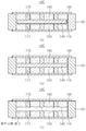
도 1 및 도 2에 도시된 바와 같이, 종래 복합 라미네이트 구조재는 제1 내면과 제1 외면이 있는 제1 금속 층(1); 제2 내면과 제2 외면이 있으며, 제1 금속 층과 이격 배치되는 제2 금속 층(2); 제1 내면 및 제2 내면 사이에 위치한 폼(10); 및 폼(10)에 의해 점유되지 않은 제1 내면 및 제2 내면 사이의 공간에 위치되고 제1 내면 및 제2 내면에 부착되는 엘라스토머로 구성된 중간층(20)을 포함한다. 여기서 엘라스토머는 플라스틱이나 폴리머 물질(plastics or polymer material)을 의미한다.As shown in FIGS. 1 and 2, a conventional composite laminate structure comprises a
폼(10)에 의해 점유되지 않은 공간은 엘라스토머인 중간층(20)으로 충전(充塡)된다.The space not occupied by the
폼(10)은 인터커넥터(12)에 의해 상호 연결된 수개의 서브섹션(11)을 포함한다. The
폼(10)은 금속 층(1,2)과, 또는 엘라스토머와 반응하지 않는 임의 종류의 경량발포제, 예를 들면 폴리우레탄(PU) 폼으로 제조될 수 있다. 폼은 밀도가 20kg/m3보다 큰 폴리프로필렌 반-경질 폼이다. 중간층(20)은 자기 중량보다 현저히 큰 하중을 지탱할 수 있도록 엘라스토머를 사용한다.The
그러나 종래 복합 라미네이트 구조재는 다음과 같은 문제들이 있다.However, the conventional composite laminated structural member has the following problems.
첫째, 종래 복합 라미네이트 구조재는, 하중과 충격만을 고려하여 제조된 구조재로서 단열을 위한 단열재로는 사용할 수 없는 한계가 있다. 즉, 금속 박스를 구성하는 제1 금속 층(1)과 제2 금속 층(2)이 상대적으로 고밀도인 엘라스토머의 중간층(20)에 접착 연결된 구조이므로, 열교 현상이 제1 금속 층(1)과 제2 금속 층(2) 전면에서 발생한다. 다시 말해서, 종래 복합 라미네이트 구조재는 그 구조상, 제1 금속 층(1)과 제2 금속 층(2)의 열전도율이 매우 높으므로, 단열재로서의 기능은 엘라스토머(elastomer)인 중간층(20) 및 내부 부속물에 의해서만 이루어진다. 하지만, 일반적으로 사용되는 엘라스토머의 열전도율(k-value)은 약 0.1774 W/mK (20℃ 기준)로, 에어로젤이나 진공단열재와 같은 단열재와는 비교조차 되지 않으며, 일반적으로 가장 널리 사용되고 있는 유기 및 무기 단열재(열전도율 0.030~0.045 W/mK)에 비해서도 단열성능이 현저히 떨어지므로, 단열재로 사용하기에는 적합하지 않다.First, the conventional composite laminated structural member is a structural member manufactured considering only the load and the impact, and thus can not be used as a heat insulating material for insulation. That is, since the
둘째, 종래 복합 라미네이트 구조재는, 폼(10)과 인터커넥터(12)와 서브섹션(11)의 높이 및 폭이 불규칙하게 형성되므로, 폴리우레탄 폼 주입시 주입공정이 매우 힘들고 주입시간이 많이 소요되는 단점이 있으며, 또한 폼(10)과 인터커넥터(12)와 서브섹션(11) 공간 안에 데드 존(dead zone)이 발생하여서 의도하지 않은 캐비티(cavity)가 생겨 복합 라미네이트 구조재 자체의 강성을 떨어뜨리는 문제가 있다.Secondly, since the height and the width of the
셋째, 종래 복합 라미네이트 구조재는, 폼(10)이 인터커넥터(12)에 의해 서브섹션(11)과 상호 연결되는 구조로, 폼(10)과 인터커넥터(12)와 서브섹션(11)의 높이 및 폭이 불규칙적으로 형성되므로, 균일한 충격흡수가 요구되는 구조재로는 적합하지 않다.Third, the conventional composite laminated structural member has a structure in which the
다시 말해서, 폼(10)의 폴리우레탄(PU) 폼은 중간층(20)의 엘라스토머보다 상대적으로 저가(低價)의 재질이므로 제조비용 절감 측면에서는 유리하지만, 도 1에 도시된 바와 같이, 제1 금속 층(1)에 가해지는 하중이 제2 금속 층(2)으로 전달될 때에, 폼(10)과 인터커넥터(12)와 서브섹션(11)의 높이 및 폭이 불규칙하게 형성되어 있기 때문에, 각 위치 (a), (b), (c), (d)에서의 충격흡수 하중이 상이하게 존재하여서 충격흡수 및 피로하중의 불균형을 초래함으로써, 복합 라미네이트 구조재 전체의 충격흡수 성능을 취약하게 하고, 피로 균열을 유발하는 문제가 있다.In other words, the polyurethane (PU) foam of the
한편, 종래 대부분의 단열재는 구조재 및 마감재로서의 특성이 없다. 따라서, 콘크리트, 목재, 철 구조와 같은 기본 구조재 시공이 선행되어야 하며, 단열재 보호 및 기밀 유지를 위해서 주의가 요하는 시공 작업 및 추가 마감재 작업이 요구된다.On the other hand, most conventional heat insulating materials have no characteristics as a structural material and a finishing material. Therefore, construction of basic structural materials such as concrete, wood, and iron structure should be preceded, and construction work and additional finishing work which require care for protection of insulation and confidentiality are required.
열전도율 0.010 W/mK 이하의 대표적 단열재는 에어로젤 단열재 및 진공단열재가 있다. 이러한 단열재들은 낮은 열전도율로 인해 기존의 유기 및 무기 단열재와 비교하여 월등히 얇은 두께로도 동일한 단열 효과를 기대할 수 있다. 하지만, 이들 모두 구조재로서의 기능은 미미하므로, 반드시 구조재를 먼저 시공한 후 별도로 상당한 주의가 요구되는 단열재 부착 시공을 하여야 그 기능을 발휘할 수 있으며, 대부분의 단열재는 단열재 보호를 위한 추가적인 마감재 공사도 요구된다.Typical insulation materials with a thermal conductivity of less than 0.010 W / mK are airgel insulation and vacuum insulation. These thermal insulation materials can be expected to have the same thermal insulation effect even with much thinner thickness than conventional organic and inorganic thermal insulation materials due to low thermal conductivity. However, since the function as a structural material is insignificant, it is necessary to apply a heat insulation material which requires a special attention after the construction material is first applied. Most of the heat insulation materials require additional finishing materials for protecting the insulation material .
특히, 진공단열재의 경우는, 충격에 매우 취약하며 기밀이 조금이라도 파손될 경우, 지속적인 가스 유입/유출로 단열 성능이 현저히 떨어질 수 있기 때문에 시공 및 마감 작업에 각별한 주의가 요구되며, 설치 이후에도 못이나 나사를 박을 수 없는 여러가지 제한 들이 수반된다.Particularly, in the case of vacuum insulation, it is very vulnerable to impact, and if a little airtightness is broken, the insulation performance due to continuous gas inflow / outflow may be considerably deteriorated, so careful attention should be paid to construction and finishing work. There are a number of limitations that can not be tolerated.
또한, 진공단열재의 경우는, 단열재 자체의 내부 진공유지가 매우 중요하다. 하지만, 진공단열재의 얇은 외피는 근본적으로 외부 충격에 취약하다. 실제로, 시공 중에 발생하는 충격으로 인해서, 단열재가 부분 파손이 발생하는 경우가 빈번하며, 이를 통한 가스 유입/유출로 단열 성능이 현저히 떨어질 수 있다. Also, in the case of a vacuum insulation material, it is very important to maintain the internal vacuum of the insulation material itself. However, the thin sheath of vacuum insulation is fundamentally vulnerable to external impacts. In fact, due to the impact generated during the construction, the thermal insulation material frequently breaks, and the insulation performance may be significantly deteriorated due to gas inflow / outflow.
또한, 미세한 틈을 통해서 지속적인 가스 유입/유출이 발생할 수 있기 때문에 내구성이나 성능 유지 측면에서 근본적인 문제가 있다.In addition, there is a fundamental problem in terms of durability and performance because continuous gas inflow / outflow can occur through fine gaps.
또한, 기존의 단열재는 운반, 설치 및 유지의 목적상 액체, 젤 타입, 기체 형태의 비정형 단열재로는 사용이 어렵기 때문에 대부분 고체형태로 제한되는 문제가 있다.In addition, existing insulation is limited to solid form because it is difficult to use as an amorphous insulation material in the form of liquid, gel or gas for the purpose of transportation, installation and maintenance.
본 발명은 전술한 문제점을 해결하기 위한 것으로, 금속재질의 하부 판과 상부 판 사이에 단열재를 설치하고, 하부 판과 단열재 사이의 공간과 상부 판과 단열재 사이의 공간에 엘라스토머를 충전함으로써, 단열재로부터의 가스의 유출 및 외부 공기의 유입이 원천적으로 차단되어 내구성 및 단열 성능을 대폭 향상시킬 수 있고, 건축물의 지붕, 벽체 및 바닥 구조, 선체 구조, LPG선 화물창 탱크 구조, 단열이 필요한 배관 구조 등에 범용(汎用)으로 적용 가능함은 물론 적용 설치시 단열재 기능과 구조재 기능이 함께 구현되므로 별도의 단열 시공이나 구조 시공이 필요 없을 뿐만 아니라, 기존에 사용되기 어려운 비정형 타입 단열재(기체, 액체, 젤 타입의 단열재)도 손쉽게 적용할 수 있는 복합 라미네이트 단열 구조재 및 그 복합 라미네이트 단열 구조재 제조방법을 제공함에 그 목적이 있다.SUMMARY OF THE INVENTION The present invention has been made in order to solve the above-mentioned problems, and it is an object of the present invention to provide a heat insulating material, The gas outflow and the inflow of outside air are fundamentally cut off, and the durability and the heat insulation performance can be greatly improved, and it is possible to improve the durability and the heat insulation performance of the roof, wall and bottom structure, hull structure, LPG cargo hold tank structure, (General purpose), as well as the insulation function and the structural function are implemented together in the installation, it is not necessary to construct a separate insulation construction or construction, and it is also possible to use an unstructured type insulation (gas, liquid, gel type insulation ) Composite laminate insulation material and its composite laminate insulation material And a manufacturing method thereof.
전술한 목적을 달성하기 위하여 복합 라미네이트 단열 구조재 및 그 복합 라미네이트 단열 구조재 제조방법을 제공한다.In order to achieve the above object, there is provided a composite laminate insulation material and a method for manufacturing the composite laminate insulation material.
본 발명의 제1 실시 예에 따른 복합 라미네이트 단열 구조재는 하측에 수평으로 위치하는 하부 판; 상기 하부 판의 상면의 테두리 부분에 설치되는 테두리 프레임; 상기 하부 판의 상측에 수평으로 위치하며, 양단부가 상기 테두리 프레임의 상면에 고정되는 상부 판; 상기 하부 판과 상기 상부 판 사이에 설치되는 단열재; 상기 하부 판과 상기 단열재 사이의 공간에 충전되는 하부 엘라스토머; 및 상기 상부 판과 상기 단열재 사이의 공간에 충전되는 상부 엘라스토머; 를 포함한다.The composite laminate heat insulating structural member according to the first embodiment of the present invention comprises a lower plate horizontally positioned on the lower side; A frame frame installed at an edge of an upper surface of the lower plate; An upper plate positioned horizontally above the lower plate and having both ends fixed to the upper surface of the frame; A heat insulating material disposed between the bottom plate and the top plate; A lower elastomer filled in a space between the lower plate and the heat insulating material; And an upper elastomer filled in a space between the top plate and the heat insulating material; .
상기 단열재는 하나의 예로서 진공단열재 또는 에어로젤 등을 포함한다.The heat insulating material includes, for example, vacuum insulating material, aerogels and the like.
상기 단열재는 단일체 구성이거나, 단위체가 복수 개로 구성된 복합체 구성중 어느 하나일 수 있다.The heat insulating material may be a monolithic structure or a composite structure composed of a plurality of unit bodies.
상기 하부 판과 상기 상부 판은 금속재로 구성할 수 있다.The lower plate and the upper plate may be made of a metal material.
상기 하부 엘라스토머와 상기 상부 엘라스토머는 개별로 형성되거나 일체로 형성되는 구성중 어느 하나로 구성될 수 있고,The lower elastomer and the upper elastomer may be formed either individually or integrally,
상기 하부 엘라스토머와 상기 상부 엘라스토머가 개별로 형성되는 경우에는 상기 하부 엘라스토머와 상기 상부 엘라스토머의 밀도 또는 성분 중 적어도 어느 하나 이상이 상이하게 구성될 수 있다.When the lower elastomer and the upper elastomer are formed separately, at least one or more of the density or the component of the lower elastomer and the upper elastomer may be different.
본 발명의 제1 실시 예에 따른 복합 라미네이트 단열 구조재는 상기 하부 판과 상기 단열재 사이의 공간을 유지하기 위한 제1 스페이서; 및 상기 상부 판과 상기 단열재 사이의 공간을 유지하기 위한 제2 스페이서; 를 더 포함한다.The composite laminate insulation material according to the first embodiment of the present invention includes: a first spacer for maintaining a space between the bottom plate and the insulation; And a second spacer for maintaining a space between the top plate and the heat insulating material; .
상기 하부 판과 상기 단열재 사이의 공간과 상기 상부 판과 상기 단열재 사이의 공간을 유지하기 위하여, 상기 테두리 프레임의 상면에 상기 단열재의 끝단 부를 지지하기 위한 단턱이 형성될 수 있다.In order to maintain a space between the lower plate and the heat insulating material and a space between the upper plate and the heat insulating material, a step for supporting the end of the heat insulating material may be formed on the upper surface of the frame.
또한, 본 발명의 제2 실시 예에 따른 복합 라미네이트 단열 구조재는 하측에 수평으로 위치하는 하부 판; 하부 판의 상면의 테두리 부분에 설치되는 테두리 프레임; 하부 판의 상측에 수평으로 위치하며, 양단부가 테두리 프레임의 상면에 고정되는 상부 판; 하부 판과 상부 판 사이에 설치되는 단열재; 하부 판과 단열재 사이의 공간에 충전되는 하부 엘라스토머; 및 상부 판과 단열재 사이의 공간에 충전되는 상부 엘라스토머를 포함하되, 테두리 프레임은 제1 테두리 프레임과, 제1 테두리 프레임과 서로 마주보게 결합하는 제2 테두리 프레임으로 구성될 수 있다.The composite laminate heat insulating structural member according to the second embodiment of the present invention includes a lower plate horizontally positioned on the lower side; A rim frame provided at a rim of an upper surface of the lower plate; An upper plate positioned horizontally above the lower plate and having both ends fixed to the upper surface of the frame frame; A heat insulating material provided between the bottom plate and the top plate; A lower elastomer charged in a space between the lower plate and the heat insulating material; And an upper elastomer filling the space between the top plate and the heat insulating material, wherein the rim frame comprises a first rim frame and a second rim frame engaging the first rim frame and facing each other.
제1 테두리 프레임과 제2 테두리 프레임은 "ㄷ"자 단면 형상을 가지며, 단열재의 양단부가 삽입되기 위한 지지 홈이 형성된다.The first frame frame and the second frame frame have a " C "cross-sectional shape, and support grooves for inserting both ends of the heat insulating material are formed.
제1 테두리 프레임과 제2 테두리 프레임은, 하부 판과 단열재 사이에 위치하는 하부 수평부재; 상부 판과 단열재 사이에 위치하는 상부 수평부재; 하부 수평부재와 상부 수평부재를 연결하는 수직부재로 구성될 수 있다.The first frame frame and the second frame frame include a lower horizontal member positioned between the bottom plate and the heat insulating material; An upper horizontal member positioned between the top plate and the heat insulating material; And a vertical member connecting the lower horizontal member and the upper horizontal member.
상기 수직부재의 양 끝단은 상기 하부 수평부재와 상기 상부 수평부재의 끝단에 용접되는 구조일 수 있다.And both ends of the vertical member may be welded to the ends of the lower horizontal member and the upper horizontal member.
또한, 본 발명의 제3 실시 예에 따른 복합 라미네이트 단열 구조재는 하측에 수평으로 위치하는 하부 판; 상기 하부 판의 상면의 테두리 부분에 설치되는 테두리 프레임; 상기 하부 판의 상방에 수평으로 위치하며, 양단부가 상기 테두리 프레임의 상면에 고정되는 상부 판; 상기 하부 판과 상기 상부 판 사이에 설치되는 단열재; 상기 하부 판과 상기 단열재 사이의 공간과, 상기 상부 판과 상기 단열재 사이의 공간에 설치되는 하, 상부 보이드 코어; 상기 하부 판과 상기 단열재 사이의 공간에 충전되는 하부 엘라스토머; 및 상기 상부 판과 상기 단열재 사이의 공간에 충전되는 상부 엘라스토머; 를 포함한다.Further, the composite laminate heat insulating structural member according to the third embodiment of the present invention includes a lower plate horizontally positioned on the lower side; A frame frame installed at an edge of an upper surface of the lower plate; An upper plate positioned horizontally above the lower plate and having both ends fixed to the upper surface of the frame; A heat insulating material disposed between the bottom plate and the top plate; An upper and a lower void core installed in a space between the lower plate and the heat insulating material, and a space between the upper plate and the heat insulating material; A lower elastomer filled in a space between the lower plate and the heat insulating material; And an upper elastomer filled in a space between the top plate and the heat insulating material; .
한편, 본 발명의 제1 실시 예에 따른 복합 라미네이트 단열 구조재 제조 방법은 판상체로 형성된 하부 판을 수평으로 설치하는 단계; 상기 하부 판의 상면의 테두리 부분에 테두리 프레임을 설치하는 단계; 상기 하부 판과 상기 상부 판 사이의 공간에 단열재를 수평으로 설치하는 단계; 상기 하측 판의 상측에 수평으로 위치하도록 상부 판의 양단부를 상기 테두리 프레임의 상면에 고정하는 단계; 및 상기 하부 판과 상기 단열재 사이의 공간에는 하부 엘라스토머를 충전하고, 상기 상부 판과 상기 단열재 사이의 공간에는 상부 엘라스토머를 충전하는 단계; 를 포함한다.Meanwhile, a method of manufacturing a composite laminated insulation material according to a first embodiment of the present invention includes the steps of: horizontally installing a lower plate formed of a plate material; Providing a rim frame on a rim of an upper surface of the lower plate; Installing a heat insulating material horizontally in a space between the bottom plate and the top plate; Fixing both ends of the upper plate to the upper surface of the frame so as to be horizontally positioned on the upper side of the lower plate; Filling a space between the lower plate and the heat insulating material with a lower elastomer and filling a space between the upper plate and the heat insulating material with an upper elastomer; .
또한, 본 발명의 제3 실시 예에 따른 복합 라미네이트 단열 구조재 제조 방법은 판상체로 형성된 하부 판을 수평으로 설치하는 단계; 하부 판의 상면 테두리 부분에 테두리 프레임을 설치하는 단계; 하부 판의 상면에 하부 보이드 코어를 설치하는 단계; 테두리 프레임의 지지 홈 안에 단열재의 단부를 탄력적으로 삽입하여 단열재를 설치하는 단계; 단열재의 상면에 상부 보이드 코어를 설치하는 단계; 상부 보이드 코어의 상측에 수평으로 위치하도록 상부 판의 양단부를 테두리 프레임의 상면에 고정하는 단계; 및 하부 판과 단열재 사이의 공간에는 하부 엘라스토머를 충전하고, 상부 판과 단열재 사이의 공간에는 상부 엘라스토머를 충전하는 단계를 포함한다.According to a third aspect of the present invention, there is provided a method of manufacturing a composite laminate heat insulating structural member, comprising: horizontally installing a lower plate formed of a plate member; Installing a rim frame on an upper surface rim of the lower plate; Installing a lower void core on the upper surface of the lower plate; Installing a heat insulating material by elastically inserting the end portion of the heat insulating material into the support groove of the frame frame; Providing an upper void core on an upper surface of the heat insulating material; Fixing both ends of the upper plate to the upper surface of the frame so as to be horizontally positioned above the upper void core; And filling the space between the bottom plate and the heat insulating material with the lower elastomer and filling the space between the top plate and the heat insulating material with the upper elastomer.
이상에서 살펴본 바와 같이, 본 발명의 적용분야 및 효과는 다음과 같다.As described above, the application fields and effects of the present invention are as follows.
1) 건축물의 지붕, 벽체 및 바닥 구조에 적용될 수 있다.1) It can be applied to roof, wall and floor structure of a building.
본 발명의 복합 라미네이트 단열 구조재가 설치되는 경우, 단열 기능과 구조기능이 함께 구현되므로 별도의 단열 시공이 필요 없게 된다. 완벽한 열교 현상 차단이 필요한 패시브 하우스(passive house)의 경우, 후속 작업으로서 열교 현상이 발생할 수 있는 금속 테두리 프레임의 접합 구역만 국부적으로 단열 시공을 수행하면 작업이 마무리될 수 있다.When the composite laminate heat insulating structural member of the present invention is installed, since the heat insulating function and the structural function are implemented together, a separate heat insulating construction is not required. In the case of a passive house requiring a complete shut-off of heat-bridging, the work may be completed by locally insulating only the joint area of the metal frame frame, which may cause thermal bridging as a subsequent operation.
2) 선박에 적용될 수 있다.2) It can be applied to ships.
온도 유지가 중요한 중 연료유 탱크 및 화학 운반선의 각종 액체 화물 탱크 구조선박의 연료로 사용되는 중 연료유(HFO)는 상온에서 점도가 매우 높기 때문에 중 연료유의 온도를 높여 유동성을 원활히 하는 장치가 필요하다. 이러한 목적으로 중 연료유 탱크 내에 각종 히팅(heating) 장비를 설치하며 그 결과 탱크 내부의 온도는 약 100℃ 정도까지 올라갈 수 있다. 기존 선박의 연료유 탱크는 모두 스틸(steel)로만 구성되어 있기 때문에 탱크를 구성하는 모든 면에서 열교 현상이 발생하여 가열 효과가 매우 떨어진다. (HFO) which is used as a fuel for ship is very high viscosity at room temperature. Therefore, it is necessary to have a device that smoothes fluidity by raising the temperature of medium fuel oil Do. For this purpose, a variety of heating equipment is installed in the fuel oil tank, and as a result, the temperature inside the tank can be increased up to about 100 ° C. Since all of the fuel oil tanks of existing vessels are made of steel only, the heat bridging phenomenon occurs on all the surfaces constituting the tank, and the heating effect is very poor.
또한, 중 연료유 탱크 인근에 설계 온도가 현저히 다른 구역(예: 냉장이 필요한 화물창)이 배치되는 경우가 빈번히 발생한다. 이 경우 탱크 외부의 단열이 요구되나 선박 구조의 특성상 단열재가 그대로 노출되어 시공된다. 예를 들어, 컨테이너선의 경우는 이러한 배치가 빈번히 발생하며, 이 경우, 컨테이너 하역 과정 중 단열재의 파손이 발생할 수 있으며 혹독한 해상 환경에 의한 유지 보수상의 여러 문제가 발생할 수 있다.In addition, it often happens that a zone with a significantly different design temperature (for example, cargo holds that require refrigeration) is placed near a medium fuel oil tank. In this case, insulation outside the tank is required, but the insulation is exposed as it is due to the nature of the ship structure. For example, in the case of a container line, this arrangement frequently occurs. In this case, the insulation of the container may be damaged during the unloading process, and various maintenance problems due to the severe marine environment may occur.
또한, 화학 운반선의 경우는, 여러 화물을 동시에 운반할 수 있도록 구분된 탱크 구조를 가지는 것이 일반적이며 화학 물질 특성에 따라 탱크 별로 다른 설계 온도를 유지하는 경우가 있다. 하지만, 금속으로 제작된 탱크 구조의 열교 현상 등으로 탱크별 온도 유지에 불가능한 경우도 발생한다. 이 경우, 부득이하게 탱크 사이에 코퍼댐(cofferdam) 또는 엠프티 탱크(empty tank)를 배치하는 경우도 발생한다.In addition, in the case of chemical carriers, it is common to have a tank structure separated to carry various cargoes at the same time. In some cases, different design temperatures are maintained for each tank depending on the chemical characteristics. However, it may not be possible to maintain the temperature of each tank due to the thermal bridge phenomenon of the metal tank structure. In this case, a cofferdam or an empty tank may be inevitably disposed between the tanks.
본 발명의 복합 라이네이트 구조 단열재를 상기와 같은 구역에 적용할 경우, 간단한 시공으로 안정적인 구조적 성능과 뛰어난 단열 성능을 동시에 확보할 수 있으며, 기존의 방식보다 얇은 구조로 시공 가능하므로 공간 활용도 측면에서 유리하고, 단열재가 튼튼한 엘라스토머(elastomer) 및 금속의 상, 하부 판으로 보호되고 있으므로, 기밀 유지 및 내 충격과 유지 보수 측면에서 월등히 우수하며, 구획 별 온도특성과 무관하게 탱크 및 구획 배치가 가능하므로 선박 구조의 활용도가 획기적으로 증대될 수 있다. When the composite lynate structure insulation material of the present invention is applied to the above-mentioned area, stable structural performance and excellent heat insulation performance can be secured at the same time by simple construction, and since it can be constructed with a thinner structure than the conventional method, And the insulation is protected by a sturdy elastomer and metal upper and lower plates. Therefore, it is superior in terms of airtightness and shock resistance and maintenance, and it is possible to arrange tanks and compartments regardless of the temperature characteristics of the compartments. The utilization of the structure can be dramatically increased.
3) 단열이 필요한 배관(pipe) 구조에 적용될 수 있다.3) It can be applied to pipe structure requiring insulation.
기존의 파이프는 여러 이유로 단열이 필요한 경우가 많다. 이 경우, 금속 파이프 위에 여러 겹의 단열재를 시공하는 번거로움이 있으며, 단열재가 외부 환경에 그대로 노출되므로 유지 보수 측면에서 근본적으로 취약하다. 진공단열재는 현재 파이프 형태로도 가공되고 있다. 이러한 진공단열재와 기존의 금속 파이프를 이용하여 손쉽게 일체형으로 제작 가능하다. 이 경우, 별도의 단열 시공 작업이 필요 없으므로 설치 작업이 간소화되며 뛰어난 단열 성능이 확보될 뿐 아니라 유지 보수가 매우 간편한 배관 작업이 가능해 진다.Conventional pipes often require insulation for a variety of reasons. In this case, it is troublesome to install multiple layers of insulation on the metal pipe, and the insulation is exposed to the external environment, which is fundamentally weak in terms of maintenance. Vacuum insulation is currently being processed in the form of a pipe. Such a vacuum insulation material and an existing metal pipe can be easily fabricated as one body. This eliminates the need for separate insulation work, which simplifies installation, provides excellent insulation performance, and makes piping work extremely easy to maintain.
4) LPG선 화물창 탱크 구조에 적용 가능하다.4) It is applicable to LPG cargo hold tank structure.
기존의 LPG 선박의 화물창 제작 방식은 철 구조에 폴리우레탄 프라이머를 바르고 그 위에 폴리우레탄을 수작업으로 분무하여 약 120~200mm 정도의 단열층을 제작한 후, 폴리우레아 코팅(polyurea coating)으로 마감하는 방식이다. 따라서, 상당한 작업 시간이 요구되고, 단열재 분무 시공 시 필연적으로 여러 비산 물질이 발생하여 환경적으로 열악하다. Conventional LPG cargo holds are made by applying a polyurethane primer to an iron structure and manually spraying polyurethane onto it to produce a heat insulation layer of about 120 to 200 mm and then closing the pipe with a polyurea coating . Therefore, a considerable working time is required, and various scattering materials are inevitably generated when spraying the thermal insulation material, which is environmentally unfavorable.
또한, 탱크 탑재 및 조립 과정에서 단열재가 시공된 이후에 여러 용접 작업이 요구되므로 화재의 위험성이 매우 높으며, 실제로 여러 조선소에서 이로 인한 대형 화재가 발생하여 인명 사고로 이어진 경우가 많다.In addition, since the welding work is required after the insulation is installed in the tank mounting and assembling process, the risk of fire is very high, and in many shipbuilding factories, there is a large fire caused by this, which leads to human accidents.
LPG선 화물창의 내부 설계 온도는 -50℃로서 화물창 구조는 저온에 버틸 수 있는 저온 강(LT 강)을 사용하여야 한다. 통상적으로 저온 강은 일반 조선 선급용 철판에 비해 고가이다.The internal design temperature of the LPG cargo holds is -50 ° C and the cargo hold structure is to be of low temperature steel (LT steel) which can withstand low temperatures. Generally, low-temperature steel is expensive compared to general steel for shipbuilding.
본 발명을 LPG선 화물창 구조에 적용할 경우, 기존의 폴리우레탄 분무 방식의 구조보다 훨씬 얇은 구조로 화물창 제작이 가능하므로 실을 수 있는 화물창 공간이 커지거나 선박 크기가 그만큼 작아질 수 있으며, 시공이 매우 간단하여 인건비를 감소할 수 있고, 화재의 위험을 근본적으로 없앨 수 있으며, LPG와 접하는 면만 LT 강으로 사용하고 외부면은 기존의 일반 조선 선급용 철판을 사용할 수 있으므로 철구조재 비용의 절감도 가능하다.When the present invention is applied to an LPG cargo hold structure, it is possible to manufacture a cargo hold structure much thinner than a conventional polyurethane spraying structure, so that the cargo hold space can be increased or the ship size can be reduced as much as possible. Because it is very simple, it can reduce the labor cost and fundamentally eliminate the risk of fire. Only LTG steel can be used for the surface that touches LPG, and the outer surface can use the existing steel plate for general shipbuilding. Do.
도 1은 상이한 형태의 종래 복합 라미네이트 구조 건축물의 측 단면도
도 2는 동일한 형태의 종래 복합 라미네이트 구조 건축물의 종단면도
도 3은 본 발명의 제1 실시 예에 따른 복합 라미네이트 단열 구조재를 도시한 분리 사시도
도 4는 본 발명의 제1 실시 예에 따른 복합 라미네이트 단열 구조재를 도시한 결합 사시도
도 5는 도 4의 I-I선 단면도
도 6은 본 발명의 제1 실시 예에 따른 복합 라미네이트 단열 구조재의 변형 예를 도시한 평면도
도 7은 도 6의 Ⅱ-Ⅱ선 단면도
도 8은 복수 개의 단위체로 구성된 플렉서블 복합단열재의 밴딩을 보인 단면도
도 9는 본 발명의 제1 실시 예에 따른 복합 라미네이트 단열 구조재의 다른 변형 예를 도시한 분리 사시도
도 10은 도 9의 종단면도
도 11은 또 다른 변형 예를 보인 종단면도
도 12는 본 발명의 제1 실시 예에 따른 복합 라미네이트 단열 구조재 제조방법을 설명하는 블록도
도 13은 본 발명의 제2 실시 예에 따른 복합 라미네이트 단열 구조재를 도시한 분리 사시도
도 14는 본 발명의 제2 실시 예에 따른 복합 라미네이트 단열 구조재를 도시한 결합 사시도
도 15는 도 14의 Ⅲ-Ⅲ선 단면도
도 16은 도 15의 변형 예를 도시한 종단면도
도 17은 본 발명의 제3 실시 예에 따른 복합 라미네이트 단열 구조재를 도시한 종단면도
도 18은 본 발명의 제3 실시 예에 따른 복합 라미네이트 단열 구조재 제조방법을 설명하는 블록도Figure 1 is a side cross-sectional view of a conventional composite laminate structure
2 is a longitudinal cross-sectional view of a conventional composite laminate structure of the same type
3 is an exploded perspective view showing a composite laminate heat insulating structural member according to a first embodiment of the present invention.
4 is a perspective view showing a combined laminate heat insulating structural member according to a first embodiment of the present invention.
5 is a sectional view taken along line II in Fig. 4
6 is a plan view showing a modified example of the composite laminate heat insulating structural member according to the first embodiment of the present invention
7 is a sectional view taken along the line II-II in Fig. 6
8 is a cross-sectional view showing the bending of the flexible composite insulation composed of a plurality of unit pieces
9 is an exploded perspective view showing another modified example of the composite laminate heat insulating structural member according to the first embodiment of the present invention.
10 is a longitudinal sectional view of Fig. 9
11 is a longitudinal sectional view showing still another modification
12 is a block diagram illustrating a method of manufacturing a composite laminate insulation structural material according to a first embodiment of the present invention
13 is an exploded perspective view showing a composite laminate heat insulating structural member according to a second embodiment of the present invention.
14 is a perspective view showing a combined laminate insulation structural member according to a second embodiment of the present invention.
15 is a sectional view taken along the line III-III in Fig. 14
16 is a longitudinal sectional view showing a modification of Fig. 15
17 is a longitudinal sectional view showing a composite laminated insulating material according to a third embodiment of the present invention
18 is a block diagram illustrating a method of manufacturing a composite laminate insulation structural material according to a third embodiment of the present invention
이하, 첨부도면을 참조하여 본 발명에 따른 복합 라미네이트 단열 구조재 및 그 복합 라미네이트 단열 구조재 제조방법에 대하여 상세하게 설명한다.DETAILED DESCRIPTION OF THE PREFERRED EMBODIMENTS The present invention will now be described in detail with reference to the accompanying drawings, in which a composite laminate insulation material and a method for manufacturing the composite laminate insulation material are described in detail.
도 3은 본 발명의 제1 실시 예에 따른 복합 라미네이트 단열 구조재를 도시한 분리 사시도, 도 4는 본 발명의 제1 실시 예에 따른 복합 라미네이트 단열 구조재를 도시한 결합 사시도, 도 5는 도 4의 I-I선 단면도, 도 6은 본 발명의 제1 실시 예에 따른 복합 라미네이트 단열 구조재의 변형 예를 도시한 평면도, 도 7은 도 6의 Ⅱ-Ⅱ선 단면도, 도 8은 복수 개의 단위체로 구성된 플렉서블 복합단열재의 밴딩을 보인 단면도, 도 9는 본 발명의 제1 실시 예에 따른 복합 라미네이트 단열 구조재의 다른 변형 예를 도시한 분리 사시도, 도 10은 도 9의 종단면도, 및 도 11은 또 다른 변형 예를 보인 종단면도이다.FIG. 3 is an exploded perspective view showing a composite laminate insulating structural member according to a first embodiment of the present invention, FIG. 4 is an assembled perspective view showing a composite laminate insulating structural member according to the first embodiment of the present invention, Fig. 6 is a plan view showing a modified example of the composite laminated thermal insulating structural member according to the first embodiment of the present invention, Fig. 7 is a sectional view taken along a line II-II in Fig. 6, and Fig. 8 is a cross- 9 is an exploded perspective view showing another modified example of the composite laminated thermal insulating structural member according to the first embodiment of the present invention, Fig. 10 is a longitudinal sectional view of Fig. 9, and Fig. 11 is a cross- Fig.
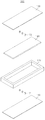
우선, 도 3 내지 도 5를 참조하면, 본 발명의 제1 실시 예에 따른 복합 라미네이트 단열 구조재(100)는 하측에 수평으로 위치하는 하부 판(110); 하부 판(110)의 상면의 테두리 부분에 설치되는 테두리 프레임(120); 하부 판(110)의 상측에 수평으로 위치하며, 양단부가 테두리 프레임(120)의 상면에 고정되는 상부 판(130); 하부 판(110)과 상부 판(130) 사이에 설치되는 단열재(140); 하부 판(110)과 단열재(140) 사이의 공간에 충전되는 하부 엘라스토머(150); 및 상부 판(130)과 단열재(140) 사이의 공간에 충전되는 상부 엘라스토머(160)를 포함한다. 엘라스토머는 플라스틱이나 폴리머 물질(plastics or polymer material)을 의미한다.3 to 5, the composite
하부 판(110)과 상부 판(130)은 강성과 단열을 유지하면서도, 상부 엘라스토머(160) 및 하부 엘라스토머(150)와의 접착성을 고려한 다양한 재질을 모두 사용할 수 있는데, 바람직하게는 금속재질로 하는 것이 가장 좋다. 하부 판(110)과 상부 판(130)은 길이가 1-10m, 폭이 0.5-5m, 두께가 3-30㎜일 수 있다.The
하부 판(110)과 상부 판(130)의 표면은 편평할 수도 있지만, 굴곡지게 형성될 수도 있고, 엠보싱 형태로 형성될 수도 있다.The surfaces of the
테두리 프레임(120)은 하부 엘라스토머(150)와 상부 엘라스토머(160)의 주위 전체를 둘러싸도록 위치되며, 그 형상은 중실 구조에 한정되지 않으며, 중공의 채널구조 등으로도 변경 가능하다.The
본 발명의 단열재(140)는 두께가 5-30㎜일 수 있으며, 수평방향으로 균일한 두께를 가지는 특징이 있다.The
단열재(140)의 균일 두께에 의하여 금속재질의 상부 판(130)에서 하부 판(110)으로 하중이 전달될 때에, 단열재(140)의 각 위치(도 1 참조)에서의 충격흡수 하중이 균일하게 존재하여서 충격흡수 및 피로하중의 균형을 유지함으로써, 복합 라미네이트 구조재 전체의 충격흡수 성능을 향상시키고, 피로 균열을 방지하는 효과가 있다.When the load is transferred from the
본 발명의 단열재로는 진공단열재는 물론, 에어로젤 단열재, 또는 슬림의 유기 단열재, 및 무기 단열재 등을 포함할 수도 있으며, 기존에 사용되기 어려운 비정형 타입 단열재(기체, 액체, 젤 타입의 단열재)도 사용할 수 있다.The insulation material of the present invention may include not only vacuum insulation materials but also air insulation materials or slim organic insulation materials and inorganic insulation materials, and it is also possible to use atypical type insulation materials (gaseous, liquid, gel type insulation materials) .
진공단열재는 양면에 금속판이 형성되고, 그 금속판 사이에 진공단열 부가 형성된 공지기술 등으로 구성될 수 있다(등록번호 제10-1243695호 참조). 에어로젤 단열재, 또는 슬림(slim)의 유기 단열재, 및 무기 단열재도 공지기술 등으로 구성될 수 있다.Vacuum heat insulators can be formed by a known technique in which a metal plate is formed on both sides and a vacuum insulation part is formed between the metal plates (refer to Registration No. 10-1243695). The aerosol insulation material or the slim organic insulation material and the inorganic insulation material may be formed by a known technique.
진공단열재의 열전도율(W/mK, 20℃ 기준)은 0.0045 이하로 한다.The thermal conductivity (W / mK, at 20 ℃) of the vacuum insulation material shall be 0.0045 or less.
에어로젤 단열재는 Aspen aerogels, Thermablok을 포함하며, 열전도율(W/mK, 20℃ 기준)은 0.000020 이하로 한다.Airgel insulation shall include Aspen aerogels and Thermablok, and the thermal conductivity (W / mK, at 20 ℃) shall be 0.000020 or less.
참고로, 열전도율과 열관류율이 낮을수록 단열성능이 높고, 열저항이 높을수록 단열성능이 높게 된다.For reference, the lower the thermal conductivity and the lower the heat conduction rate, the higher the insulation performance. The higher the thermal resistance, the higher the insulation performance.
본 발명의 단열재로 사용할 수 있는 단열재는 아래 표 1과 같다.Table 1 below shows the heat insulating materials usable as the heat insulating material of the present invention.
또한, 하부 엘라스토머(150)와 상부 엘라스토머(160)는 탄성률(E)이 최저 예상 온도, 조선 적용의 경우는, 5000MPa 미만으로 하여 지나치게 강성을 띠지 않도록 하는 것이 일반적이다.In general, the elastic modulus E of the
또한, 하부 엘라스토머(150)와 상부 엘라스토머(160)는 도 5의 (a)에 도시된 바와 같이 일체로 형성되는 구성이거나, 도 5의 (b)에 도시된 바와 같이 개별로 형성되는 구성 중 어느 하나로 구성될 수 있다.The
하부 엘라스토머(150)와 상부 엘라스토머(160)가 개별로 형성되는 경우에는 하부 엘라스토머(150)와 상부 엘라스토머(160)의 밀도와 성분이 상이하게 구성될 수도 있다. When the
이와 같이 하부 엘라스토머(150)와 상부 엘라스토머(160)의 밀도를 상이하게 하는 이유는, 하부 판(110)에 접하는 부분과 상부 판(130)에 접하는 부분의 단열을 달리해야 하는 곳에 사용할 경우, 그에 맞게 하부 엘라스토머(150)와 상부 엘라스토머(160)의 밀도 및 성분을 상이하게 구성함으로써, 상면과 하면의 설계하중 온도 및 조건이 다른 경우가 발생하기 때문이다. 따라서 각 설계조건에 맞는 최적의 성분을 갖는 엘라스토머를 배치함으로써 최적의 구조 및 단열성능을 발휘할 수 있다.The reason for making the density of the
한편, 재료 형상에 따라 단열 공법을 구분하면 성형판, 발포형, 뿜칠형 단열공법으로 나눌 수 있으나, 이러한 단열 공법들로 제작된 단열재들은 모두 제작 후에 고체 형태의 단열 구조를 가진다. On the other hand, according to the shape of the material, it is possible to divide the insulation method into a molded plate, a foamed type, and a blown type. However, all of the heat insulating materials manufactured by the above methods have a solid insulating structure.
즉, 대부분의 단열재는 내부에 작은 기포들이 포함되어 있는 고체이다. 하지만, 열역학적 측면에서 보면, 고체보다는 비정형성 물질인 액체, 젤 및 기체로 단열재를 제작하는 것이 훨씬 더 좋다. 고체의 열전도 계수는 액체의 열전도 계수보다 크며, 액체의 열전도계수는 기체의 열전도 계수보다 약 100배 이상 더 크지만, 운반, 시공 및 유지 보수의 측면에서 큰 단점이 존재하여 비정형성 단열재는 거의 사용되지 않는다.In other words, most insulation is a solid containing small bubbles inside. However, from a thermodynamic standpoint, it is much better to make insulation from liquid, gel, and gas, which are non-crystalline materials rather than solids. Although the thermal conductivity coefficient of a solid is greater than the thermal conductivity coefficient of a liquid and the thermal conductivity coefficient of the liquid is about 100 times greater than the thermal conductivity coefficient of the gas, there is a great disadvantage in terms of transportation, construction and maintenance, It does not.
하지만, 도 5의 (3)에 도시된 바와 같이, 본 발명에서는 기존에 사용되기 어려운 비정형 타입 단열재(기체, 액체, 젤 타입의 단열재)(140)도 손쉽게 적용 가능하다. 즉, 에어 매트와 같은 플렉서블 용기(flexible vessel)에 비정형성 단열 물질을 주입하여 임시 비정형 단열재를 만들어 적용하면 손쉽게 비정형성 단열재로도 본 발명의 복합 라미네이트 단열 구조재를 제작할 수 있다. 즉, 순차적으로 하부 판(110)을 설치하고, 그 하부 판(110) 위에 테두리 프레임(120)을 설치하며, 하부 판(110)의 상면에 하부 스페이서(171)를 설치하고, 임시의 비정형 단열재(140)를 삽입한 후, 그 플렉서블 용기의 상면에 상부 스페이서(172)를 설치하고, 하부 및 상부 엘라스토머(150)(160)를 주입하는 방식으로 제작할 수 있다.However, as shown in FIG. 5 (3), the present invention can be easily applied to an irregular-type heat insulating material (gas, liquid, gel-type heat insulating material) That is, if a temporary non-seamless insulation material is injected into a flexible vessel such as an air mat to form a temporary atypical insulation material, the composite laminate insulation material of the present invention can be easily fabricated as a non-seamless insulation material. That is, the
비정형 타입의 단열재(140)를 엘라스토머(elastomer)가 주입 및 경화되는 시간(통상 약 4시간) 동안에, 어느 정도의 압력만 견딜 수 있는 플렉서블 용기에 담은 후, 고체 단열재와 같은 방식으로 수평방향(평면방향)으로 균일하게 배치한 후, 본 발명의 복합 라미네이트 단열 구조재로 만들면, 내부의 유동형태의 비정형 단열재(140)가 금속 박스(상, 하부 판과 테두리 프레임이 이루는 공간) 및 상, 하부 엘라스토머(160,150)로 둘러싸여 보호될 수 있다. 플렉서블 용기는 합성수지 등을 포함한다.The irregular
또한, 단열재(140)는 도 3 내지 도 5에 도시된 바와 같이 단일체 구성될 수도 있고, 도 6 및 도 7에 도시된 바와 같이 복수 개의 단위체가 서로 연결된 복합체로 구성될 수도 있다.In addition, the
금속재질인 하부 판(110)과 상부 판(130)은 열변형에 의한 거동(movement)이 수반되므로, 하중에 의한 밴딩 시에 복합체로 구성된 단열재(140)가 도 8에 도시된 바와 같이 여유있게 휘어져서 단열재(140)의 파손이나 손상을 효과적으로 방지할 수 있다.Since the
또한, 단열재(140)를 하부 판(110)과 상부 판(130) 사이의 공간에 일정간격을 유지하여 지지하는 구조는 도 3 내지 5에 도시된 스페이서 구조, 또는 도 9 및 도 10에 도시된 단턱 구조일 수 있다.The structure for supporting the
도 3 내지 5에 도시된 바와 같이, 하부 판(110)과 단열재(140) 사이의 공간을 유지하기 위하여 제1 스페이서(171)가 구비되고, 상부 판(130)과 단열재(140) 사이의 공간을 유지하기 위하여 제2 스페이서(172)가 구비될 수 있다.3 to 5, a
제1 스페이서(171) 및 제2 스페이서(172)의 설치 개수와, 서로 간의 설치간격은 도면에 표시된 것에 한정되지 않으며, 설계조건에 따라 변경될 수 있다. 제1 스페이서(171) 및 제2 스페이서(172)의 재질은 고밀도의 엘라스토머를 사용할 수도 있다.The number of the
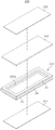
또한, 도 9 및 도 10에 도시된 바와 같이, 하부 판(110)과 단열재(140) 사이의 공간과, 상부 판(130)과 단열재(140) 사이의 공간을 유지하기 위하여, 테두리 프레임(120)의 상면에 단열재(140)의 끝단 부를 지지하기 위한 단턱(121)이 형성될 수도 있다.9 and 10, in order to maintain a space between the
또한, 도 11에 도시된 바와 같이, 스페이서(171,172) 구조와 단턱(121) 구조가 함께 적용됨으로써, 구조적 강도 및 안전성을 높일 수 있다.11, the structure of the
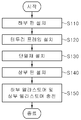
한편, 이와 같이 구성된 본 발명의 제1 실시 예에 따른 복합 라미네이트 단열 구조재(100) 제조방법은, 판상체로 형성된 하부 판(110)을 수평으로 설치하는 단계(S110); 하부 판(110)의 상면의 테두리 부분에 테두리 프레임(120)을 설치하는 단계(S120); 하부 판(110)과 상부 판(130) 사이의 공간에 단열재(140)를 수평으로 설치하는 단계(S130); 하측 판(110)의 상측에 수평으로 위치하도록 상부 판(130)의 양단부를 테두리 프레임(120)의 상면에 고정하는 단계(S140); 및 하부 판(110)과 단열재(140) 사이의 공간에는 하부 엘라스토머(150)를 충전하고, 상부 판(130)과 단열재(140) 사이의 공간에는 상부 엘라스토머(160)를 충전하는 단계(S150)를 포함한다.Meanwhile, the method of fabricating the composite laminate heat insulating
본 발명의 제1 실시 예에 따른 복합 라미네이트 단열 구조재(100) 제조방법에서는 하부 엘라스토머(150)와 상부 엘라스토머(160)를 개별로 충전하거나 일체로 충전하는 방법 중 어느 하나를 택일할 수 있다.In the method for manufacturing a composite laminate heat insulating
하부 엘라스토머(150)와 상부 엘라스토머(160)를 개별로 충전하는 경우에는 하부 엘라스토머(150)와 상부 엘라스토머(160)의 밀도를 상이하게 구성할 수 있다.When the
전술한 바와 같이, 하부 판(110)에 접하는 부분과 상부 판(130)에 접하는 부분의 단열을 달리해야 하는 곳에 사용할 경우, 그에 맞게 하부 엘라스토머(150)와 상부 엘라스토머(160)의 밀도와 성분을 상이하게 구성함으로써, 상면과 하면의 설계하중 온도 및 조건이 다른 경우가 발생하기 때문이다. 따라서 각 설계조건에 맞는 최적의 성분을 갖는 엘라스토머를 배치함으로써 최적의 구조 및 단열성능을 발휘할 수 있다.As described above, in a case where the portion contacting the
하부 엘라스토머(150)와 상부 엘라스토머(160)를 일체로 충전하는 방법은 하부 엘라스토머(150)와 상부 엘라스토머(160) 양측에서 동시에 충전하거나 일측에서 충전할 수 있다.The method of integrally charging the
한편, 도 13은 본 발명의 제2 실시 예에 따른 복합 라미네이트 단열 구조재를 도시한 분리 사시도, 도 14는 본 발명의 제2 실시 예에 따른 복합 라미네이트 단열 구조재를 도시한 결합 사시도, 도 15는 도 14의 Ⅲ-Ⅲ선 단면도, 도 16은 도 15의 변형 예를 도시한 종단면도이다.FIG. 13 is an exploded perspective view showing a composite laminate insulating structural member according to a second embodiment of the present invention, FIG. 14 is an assembled perspective view showing a composite laminate insulating structural member according to a second embodiment of the present invention, FIG. 14 is a sectional view taken along line III-III of Fig. 15, and Fig. 16 is a longitudinal sectional view showing a modification of Fig.
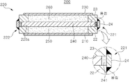
먼저, 도 13 내지 도 15를 참조하면, 본 발명의 제2 실시 예에 따른 복합 라미네이트 단열 구조재(200)는 하측에 수평으로 위치하는 하부 판(210); 하부 판(210)의 상면의 테두리 부분에 설치되는 테두리 프레임(220); 하부 판(210)의 상측에 수평으로 위치하며, 양단부가 테두리 프레임(220)의 상면에 고정되는 상부 판(230); 하부 판(210)과 상부 판(230) 사이에 설치되는 단열재(240); 하부 판(210)과 단열재(240) 사이의 공간에 충전되는 하부 엘라스토머(250); 및 상부 판(230)과 단열재(240) 사이의 공간에 충전되는 상부 엘라스토머(260)를 포함한다.13 to 15, a composite
테두리 프레임(220)은 제1 테두리 프레임(221)과, 제1 테두리 프레임(221)과 서로 마주보게 결합하는 제2 테두리 프레임(222)으로 구성될 수 있다.The
제1 테두리 프레임(221)과 제2 테두리 프레임(222)은 "ㄷ"자 단면 형상을 가지며, 단열재(240)의 양단부가 삽입되기 위한 지지 홈(220a)이 형성된다.The
제1 테두리 프레임(221)과 제2 테두리 프레임(222)은, 하부 판(210)과 단열재(240) 사이에 위치하는 하부 수평부재(22); 상부 판(230)과 단열재(240) 사이에 위치하는 상부 수평부재(23); 하부 수평부재(22)와 상부 수평부재(23)를 연결하는 수직부재(24)로 구성될 수 있다.The
하부 판(210)의 끝단 부는 하부 수평부재(22)의 하면 면적의 1/2 이하로 접하게 되고, 상부 판(210)의 끝단 부는 상부 수평부재(23)의 하면 면적의 1/2 이하로 접하게 하는 것이 열전도율 측면과 강도 측면에서 바람직하다(도 15 참조). The end of the
다시 말해서, 하부 판(210) 및 상부 판(210)과 테두리 프레임(220)의 연결면적을 최소한으로 구성하여 복합 라미네이트 단열 구조재 자체의 강성을 유지하면서도 열전도율을 낮추어 단열성능을 높이도록 하는 것이 바람직하다. In other words, it is preferable that the connection area between the
수직부재(24)의 양 끝단은 하부 수평부재(22)와 상부 수평부재(23)의 끝단에 용접되는 구조가 바람직하다.It is preferable that both ends of the
또한, 도 16에 도시된 바와 같이, 단열재(240)의 양단에 쿠션 부재(241)를 추가하여 금속재질인 하부 판(210)과 상부 판(230)의 밴딩과 수평방향 신축현상 발생 시에, 단열재(240)의 변형이나 파손을 효과적으로 방지할 수 있다.16, when a
한편, 도 17은 본 발명의 제3 실시 예에 따른 복합 라미네이트 단열 구조재를 도시한 종단면도이고, 도 18은 본 발명의 제3 실시 예에 따른 복합 라미네이트 단열 구조재 제조방법을 설명하는 블록도이다.17 is a longitudinal sectional view showing a composite laminate insulation material according to a third embodiment of the present invention, and FIG. 18 is a block diagram illustrating a method of manufacturing a composite laminate insulation material according to a third embodiment of the present invention.
도 17을 참조하면, 본 발명의 제3 실시 예에 따른 복합 라미네이트 단열 구조재(300)는 하측에 수평으로 위치하는 하부 판(310); 하부 판(310)의 상면의 테두리 부분에 설치되는 테두리 프레임(320); 하부 판(310)의 상방에 수평으로 위치하며, 양단부가 테두리 프레임(320)의 상면에 고정되는 상부 판(330); 하부 판(310)과 상부 판(330) 사이에 설치되는 단열재(340); 하부 판(310)과 단열재(340) 사이의 공간과, 상부 판(330)과 단열재(340) 사이의 공간에 설치되는 하, 상부 보이드 코어(일명, 버블 코어)(380)(390); 하부 판(310)과 단열재(340) 사이의 공간에 충전되는 하부 엘라스토머(350); 상부 판(330)과 단열재(340) 사이의 공간에 충전되는 상부 엘라스토머(360)를 포함한다.Referring to FIG. 17, a composite
하부 판(310)과 상부 판(330)은 강성과 단열을 유지하면서도, 상부 엘라스토머(360) 및 하부 엘라스토머(350)와의 접착성을 고려한 다양한 재질이라면 모두 사용할 수 있는데, 바람직하게는 금속재질로 하는 것이 가장 좋다.The
테두리 프레임(320)은 중실 구조에 한정되지 않으며, 중공의 채널구조 등으로도 변경 가능하다. 테두리 프레임(320)은 2개로 구성되는 것뿐만 아니라 4개로 구성될 수도 있다.The
단열재(340)는 진공단열재는 물론, 에어로젤 단열재, 또는 슬림(slim)의 유기 및 무기 단열재 등을 포함한다.The
진공단열재(340)의 열전도율(W/mK, 20℃ 기준)은 0.0045 이하로 한다.The thermal conductivity (W / mK, at 20 ° C) of the
에어로젤 단열재는 Aspen aerogels, Thermablok을 포함하며, 열전도율(W/mK, 20℃ 기준)은 0.000020 이하로 한다.Airgel insulation shall include Aspen aerogels and Thermablok, and the thermal conductivity (W / mK, at 20 ℃) shall be 0.000020 or less.
하부 엘라스토머(350)와 상부 엘라스토머(360)는 개별로 형성되거나, 일체로 형성되는 구성중 어느 하나로 구성될 수 있는데, 하부 엘라스토머(250)와 상부 엘라스토머(360)가 개별로 형성되는 경우에는 하부 엘라스토머(350)와 상부 엘라스토머(360)의 밀도, 성분 등을 상이하게 구성할 수 있다.When the
전술한 바와 같이, 하부 판(310)에 접하는 부분과 상부 판(330)에 접하는 부분의 단열을 달리해야 하는 곳에 사용할 경우, 그에 맞게 하부 엘라스토머(350)와 상부 엘라스토머(360)의 밀도 또는 성분을 상이하게 구성함으로써, 상면과 하면의 설계하중 온도 및 조건이 다른 경우가 발생하기 때문이다. 따라서 각 설계조건에 맞는 최적의 성분을 갖는 엘라스토머를 배치함으로써 최적의 구조 및 단열성능을 발휘할 수 있다.As described above, when the portion contacting the
또한, 도 18을 참조하면, 본 발명의 제3 실시 예에 따른 복합 라미네이트 단열 구조재(300) 제조방법은 판상체로 형성된 하부 판(310)을 수평으로 설치하는 단계(S310); 하부 판(310)의 상면 테두리 부분에 테두리 프레임(320)을 설치하는 단계(S320); 하부 판(310)의 상면에 하부 보이드 코어(380)를 설치하는 단계(S330); 테두리 프레임(320)의 지지 홈(320a) 안에 단열재(340)의 단부를 탄력적으로 삽입하여 단열재(340)를 설치하는 단계(S340); 단열재(340)의 상면에 상부 보이드 코어(390)를 설치하는 단계(S350); 상부 보이드 코어(390)의 상측에 수평으로 위치하도록 상부 판(330)의 양단부를 테두리 프레임(320)의 상면에 고정하는 단계(S360); 및 하부 판(310)과 단열재(340) 사이의 공간에는 하부 엘라스토머(350)를 충전하고, 상부 판(330)과 단열재(340) 사이의 공간에는 상부 엘라스토머(360)를 충전하는 단계(S370)를 포함한다.Referring to FIG. 18, a method of fabricating a composite
테두리 프레임(320)은 제1 테두리 프레임(321)과, 제1 테두리 프레임(321)과 서로 마주보게 결합하는 제2 테두리 프레임(322)으로 구성될 수 있다.The
하부 엘라스토머(350)와 상부 엘라스토머(360)를 개별로 충전하거나 일체로 충전하는 방법 중 어느 하나를 택일할 수 있다.The
하부 엘라스토머(350)와 상부 엘라스토머(360)를 개별로 충전하는 경우에는 하부 엘라스토머(350)와 상부 엘라스토머(360)의 밀도, 성분 등을 상이하게 구성할 수 있다.When the
전술한 바와 같이, 하부 판(310)에 접하는 부분과 상부 판(330)에 접하는 부분의 단열을 달리해야 하는 곳에 사용할 경우, 그에 맞게 하부 엘라스토머(350)와 상부 엘라스토머(360)의 밀도 또는 성분 등을 상이하게 구성함으로써, 상면과 하면의 설계하중 온도 및 조건이 다른 경우가 발생하기 때문이다. 따라서 각 설계조건에 맞는 최적의 성분을 갖는 엘라스토머를 배치함으로써 최적의 구조 및 단열성능을 발휘할 수 있다.As described above, when the portion contacting the
한편, 단열 성능을 높이기 위해서는 분자 간의 열 전달을 최대한 억제하여야 하는데, 분자들이 촘촘하게 배열된 고밀도의 자재로는 적정한 단열성능을 기대하기 어렵기 때문에, 단열재 자체만으로는 구조재로서의 성능을 기대할 수 없다. 따라서, 기존 단열재에는 콘크리트, 철 구조, 목재 등의 기초 구조 설비 작업이 반드시 더 추가로 선행되어야 한다. On the other hand, in order to increase the heat insulation performance, the heat transfer between the molecules should be suppressed to the utmost. However, since the high-density materials in which the molecules are arranged closely are not expected to have proper heat insulation performance, the heat insulation itself can not be expected as a structural material. Therefore, the existing insulation materials must be preceded by further work on the foundation structure of concrete, iron structure, and wood.
또한, 단열 성능을 유지하기 위해서는 부재 간의 기밀한 접합이 매우 중요하므로 구조재와의 접합 시공 시 상당한 주의를 요하고, 다양한 접합재가 요구된다. 그리고 대부분의 건축 사업의 경우는, 단열재의 보호를 위한 추가 마감재 작업이 요구되므로, 이에 따른 비용 및 시간이 수반된다. 에어로젤 단열재의 경우는 90~95% 이상의 높은 기공률로 인해서 기계적인 강도 측면에서 매우 취약하며 작은 충격에도 파손될 수 있다. 이러한 단점을 보완하기 위해서 파이버와 에어로젤의 복합 재료를 사용함으로써, 유연성을 높이고 기계적인 특성을 보완한 에어로젤 Blanket 타입의 단열재가 개발되었지만, 이 경우에도 구조재로서의 특성은 미미하기 때문에 구조재 작업이 선행된 후 별도의 단열재 부착 시공이 추가로 요구된다.In addition, in order to maintain the heat insulation performance, since the airtight bonding between the members is very important, a great deal of care is required when joining with a structural member, and various bonding materials are required. And, for most construction projects, additional finishing work is required for the protection of the insulation, resulting in cost and time. In the case of airgel insulation, it is very weak in terms of mechanical strength due to a high porosity of 90 to 95% or more and may be damaged even in a small impact. In order to overcome these disadvantages, airgel Blanket type heat insulation material which improves flexibility and mechanical properties has been developed by using composite material of fiber and aerogels. However, even in this case, since the characteristic as a structural material is insignificant, Additional installation of additional insulation is required.
또한, 파이프류나 가스탱크 등에 적용될 경우, 대부분 단열재를 그대로 외부에 노출해 시공하기 때문에 외부 환경에 의한 내구성 및 유지 보수 문제가 발생할 수 있다.In addition, when it is applied to a pipe or a gas tank, since most of the heat insulating material is exposed to the outside as it is, durability and maintenance problems due to external environment may occur.
본 발명의 복합 라미네이트 구조 단열재는 전술한 여러 가지 문제점들을 모두 감안하여 발명한 것으로, 1) 엘라스토머(elastomer) 주입 시, 진공단열재의 파손 여부, 2) 단열성능의 확보, 3) 단열재의 기밀성 유지, 4) 외부 충격에 대한 단열재의 보호, 5) 구조재로서의 성능구현 측면을 살펴보기로 한다.The composite laminate structure insulating material of the present invention was invented in consideration of all of the above-mentioned problems, and it was found that (1) when the elastomer is injected, the vacuum insulation material is broken, (2) the insulation performance is secured, (3) the airtightness of the insulation material is maintained, 4) protection of the insulation against external impact, and 5) performance as a structural material.
1) 엘라스토머(elastomer) 주입 시 진공단열재의 파손 여부1) Damage of vacuum insulation material when injecting elastomer
대부분의 진공단열재는 충격에는 취약하나 압축 로드(compression load) 측면에서는 어느 정도의 강도가 있다. 예를 들어, Fumed silica 방식의 진공단열재의 경우는, 압축 로드가 20㎜의 진공단열패널이 약 8~10 N/㎠ 정도이다. 금속 박스에 액체 상태의 엘라스토머를 주입하면 이후 경화가 일어나면서 온도가 상승하며 팽창 압력이 발생한다. 이때의 발생 압력은 1 N/㎠을 넘지 않는다. 실제로, 기존의 복합 라미네이트 구조를 만들기 위한 엘라스토머 주입 작업 전에 기밀성능시험(air tightness test)을 수행하는 데, 이때의 압력 기준도 대략 1~2 N/㎠ 정도의 압력을 사용하는 것으로 알려진다. 따라서, 엘라스토머 주입 과정(복합 라미네이트 단열 구조재 제작 과정)에서 진공단열재가 파손되어 단열재 내부가스가 유출/유입될 가능성은 전혀 없다.Most vacuum insulation is susceptible to impact but has some strength in terms of compression load. For example, in the case of fumed silica type vacuum insulation material, a vacuum insulation panel having a compression load of 20 mm is about 8 to 10 N /
2) 단열성능의 확보2) Securing insulation performance
패시브 하우스(passive house) 열관류율 기준인 0.15 W/m2K를 만족하는 복합 라미네이트 단열 구조재를 제공한다. 일 예로서, 금속재질의 상부 판, 상부 엘라스토머, 진공단열재, 하부 엘라스토머, 금속재질의 하부 판으로 구성된 복합 라미네이트 단열 구조재 두께를 각각 4-5㎜, 15-20㎜, 10-20㎜, 15-20㎜, 4-5㎜로 최적화하여 구성함으로써, 단열성능을 충분히 확보할 수 있다.And 0.15 W / m 2 K, which is the passive house heat conduction ratio standard. For example, the thickness of the composite laminate insulation material composed of a metal top plate, an upper elastomer, a vacuum insulation material, a lower elastomer, and a metal bottom plate is set to 4-5 mm, 15-20 mm, 10-20 mm, 20 mm, and 4-5 mm, the heat insulation performance can be sufficiently secured.
3) 단열재의 기밀성 유지3) Keep airtightness of insulation
엘라스토머 주입 전에 기밀성능시험(air tightness test)을 수행한다. 이보다 확실한 이유는 주입된 액체 상태의 엘라스토머가 경화되면서 자연스럽게 진공단열재 및 금속 박스(상, 하부 판과 테두리 프레임이 이루는 공간)의 내부 면과 기밀하게 접합되고 경화된 폴리우레탄 내부에는 공기가 존재하지 않으므로 진공단열재의 가스 유출/유입이 원천적으로 차단됨으로써, 단열재의 기밀성 유지를 확인할 수 있다.An air tightness test is performed before the elastomer injection. The more obvious reason is that since the injected liquid elastomer is cured and naturally bonded to the inner surface of the vacuum insulation and metal box (the space formed by the upper and lower plates and frame frame) and there is no air inside the hardened polyurethane The gas outflow / inflow of the vacuum insulator is fundamentally blocked, so that the airtightness of the heat insulator can be confirmed.
4) 외부충격에 대한 단열재의 보호4) Protection of insulation against external impact
복합 라미네이트 단열 구조재가 외부로부터 충격을 받을 경우, 일차적으로 금속의 상, 하부 판이 충격을 받고, 그 다음 내부의 폴리우레탄인 엘라스토머가 그 충격을 전달받게 된다. 즉, 단열재의 외부가 금속의 상, 하부 판과 폴리우레탄으로 둘러싼 구조로 보호되는 구조로서, 외부 충격에 대하여 단열재를 충분히 보호함으로써, 해양구조물의 선체 외벽, 갑판 등에 널리 사용할 수 있다.When the composite laminate heat insulating structural member is impacted from the outside, the upper and lower plates of the metal are primarily impacted, and then the inner polyurethane elastomer receives the impact. That is, a structure in which the outside of the heat insulating material is protected by a structure surrounded by the metal upper and lower plates and polyurethane, can be widely used on the outer wall of the hull, deck, etc. of an offshore structure by sufficiently protecting the heat insulating material against external impact.
5) 구조재로서의 성능 구현5) Performance as a structural material
복합 라미네이트 단열 구조재가 안정적인 구조재로서의 특성을 유지하기 위해서는, 금속 박스를 구성하는 상, 하부 판과 엘라스토머와의 전반적인 접합성이 유지되어야 한다.In order for the composite laminate insulating structural material to maintain its properties as a stable structural material, the overall bonding property between the upper and lower plates constituting the metal box and the elastomer should be maintained.
본 발명의 구조에 따르면, 상부 판 및 하부 판의 내측 면이 상, 하부 엘라스토머와 기밀하게 부착되어 있다. 단열재는 이미 기존 구조재의 표면에 별도로 접합되는 방식으로 다양한 종류의 구조물에 적용되고 있다. 즉, 통상적인 설계 하중을 만족하는 구조재의 거동에 따른 단열재의 파손 여부의 문제는 이미 해결되었다고 볼 수 있다. 따라서, 본 발명의 복합 라미네이트 단열 구조재를 구성하는 각 재질 간의 응력 및 하중 전달 문제도 해결된다. According to the structure of the present invention, the inner surfaces of the upper plate and the lower plate are hermetically attached to the upper and lower elastomers. Insulation has been applied to various types of structures in such a way that they are already bonded to the surface of existing structural members. In other words, it can be said that the problem of the breakage of the insulation due to the behavior of the structural material satisfying the normal design load has already been solved. Therefore, stress and load transfer problems between the respective materials constituting the composite laminate heat insulating structural member of the present invention are also solved.
또한, 도 4 및 도 5에 도시된 바와 같이 복수의 단위체로 구성된 복합체 형태로 진공단열재를 배치하는 경우는, 설계 하중을 초과하는 힘을 받아서 지나치게 밴딩(bending) 된 상태에서도 단열재의 파손 또는 열교 현상 없이 단열 성능을 효과적으로 유지할 수 있다.4 and 5, in the case of disposing the vacuum insulator in the form of a complex composed of a plurality of unit pieces, even when the vacuum insulator is subjected to a force exceeding the design load and is excessively bending, It is possible to effectively maintain the insulation performance.
또한, 금속재질의 상부 판에 가해지는 하중이 하부 판으로 전달될 때에, 단열재가 수평방향으로 균일하게 설치되어 있으므로, 충격흡수 하중이 균일하게 존재하여서 충격흡수 및 피로하중의 균형을 항상 유지하여 복합 라미네이트 단열 구조재 전체의 충격흡수 성능 및 강성을 더욱 향상시키고, 피로 균열 현상을 효과적으로 방지할 수 있다.In addition, when the load applied to the upper plate of the metal material is transmitted to the lower plate, since the heat insulating material is uniformly installed in the horizontal direction, the shock absorbing load is uniformly present so that the balance of shock absorption and fatigue load is always maintained It is possible to further improve the shock absorbing performance and rigidity of the entire laminate heat insulating structural member and effectively prevent the fatigue cracking phenomenon.
한편, 본 발명의 적용분야 및 효과는 다음과 같다.The application fields and effects of the present invention are as follows.
1) 건축물의 지붕, 벽체 및 바닥 구조에 적용될 수 있다.1) It can be applied to roof, wall and floor structure of a building.
본 발명의 복합 라미네이트 단열 구조재가 설치되는 경우, 단열 기능과 구조기능이 함께 구현되므로 별도의 단열 시공이 필요 없게 된다. 완벽한 열교 현상 차단이 필요한 패시브 하우스(passive house)의 경우, 후속 작업으로서 열교 현상이 발생할 수 있는 금속 테두리 프레임의 접합 구역만 국부적으로 단열 시공을 수행하면 작업이 마무리될 수 있다.When the composite laminate heat insulating structural member of the present invention is installed, since the heat insulating function and the structural function are implemented together, a separate heat insulating construction is not required. In the case of a passive house requiring a complete shut-off of heat-bridging, the work may be completed by locally insulating only the joint area of the metal frame frame, which may cause thermal bridging as a subsequent operation.
2) 선박에 적용될 수 있다.2) It can be applied to ships.
온도 유지가 중요한 중 연료유 탱크 및 화학 운반선의 각종 액체 화물 탱크 구조선박의 연료로 사용되는 중 연료유(HFO)는 상온에서 점도가 매우 높기 때문에 중 연료유의 온도를 높여 유동성을 원활히 하는 장치가 필요하다. 이러한 목적으로 중 연료유 탱크 내에 각종 히팅(heating) 장비를 설치하며 그 결과 탱크 내부의 온도는 약 100℃ 정도까지 올라갈 수 있다. 기존 선박의 연료유 탱크는 모두 스틸(steel)로만 구성되어 있기 때문에 탱크를 구성하는 모든 면에서 열교 현상이 발생하여 가열 효과가 매우 떨어진다. (HFO) which is used as a fuel for ship is very high viscosity at room temperature. Therefore, it is necessary to have a device that smoothes fluidity by raising the temperature of medium fuel oil Do. For this purpose, a variety of heating equipment is installed in the fuel oil tank, and as a result, the temperature inside the tank can be increased up to about 100 ° C. Since all of the fuel oil tanks of existing vessels are made of steel only, the heat bridging phenomenon occurs on all the surfaces constituting the tank, and the heating effect is very poor.
또한, 중 연료유 탱크 인근에 설계 온도가 현저히 다른 구역(예: 냉장이 필요한 화물창)이 배치되는 경우가 빈번히 발생한다. 이 경우 탱크 외부의 단열이 요구되나 선박 구조의 특성상 단열재가 그대로 노출되어 시공된다. 예를 들어, 컨테이너선의 경우는 이러한 배치가 빈번히 발생하며, 이 경우, 컨테이너 하역 과정 중 단열재의 파손이 발생할 수 있으며 혹독한 해상 환경에 의한 유지 보수상의 여러 문제가 발생할 수 있다.In addition, it often happens that a zone with a significantly different design temperature (for example, cargo holds that require refrigeration) is placed near a medium fuel oil tank. In this case, insulation outside the tank is required, but the insulation is exposed as it is due to the nature of the ship structure. For example, in the case of a container line, this arrangement frequently occurs. In this case, the insulation of the container may be damaged during the unloading process, and various maintenance problems due to the severe marine environment may occur.
또한, 화학 운반선의 경우는, 여러 화물을 동시에 운반할 수 있도록 구분된 탱크 구조를 가지는 것이 일반적이며 화학 물질 특성에 따라 탱크 별로 다른 설계 온도를 유지하는 경우가 있다. 하지만, 금속으로 제작된 탱크 구조의 열교 현상 등으로 탱크별 온도 유지에 불가능한 경우도 발생한다. 이 경우, 부득이하게 탱크 사이에 코퍼댐(cofferdam) 또는 엠프티 탱크(empty tank)를 배치하는 경우도 발생한다.In addition, in the case of chemical carriers, it is common to have a tank structure separated to carry various cargoes at the same time. In some cases, different design temperatures are maintained for each tank depending on the chemical characteristics. However, it may not be possible to maintain the temperature of each tank due to the thermal bridge phenomenon of the metal tank structure. In this case, a cofferdam or an empty tank may be inevitably disposed between the tanks.
본 발명의 복합 라이네이트 구조 단열재를 상기와 같은 구역에 적용할 경우, 간단한 시공으로 안정적인 구조적 성능과 뛰어난 단열 성능을 동시에 확보할 수 있으며, 기존의 방식보다 얇은 구조로 시공 가능하므로 공간 활용도 측면에서 유리하고, 단열재가 튼튼한 엘라스토머(elastomer) 및 금속의 상, 하부 판으로 보호되고 있으므로, 기밀 유지 및 내 충격과 유지 보수 측면에서 월등히 우수하며, 구획 별 온도특성과 무관하게 탱크 및 구획 배치가 가능하므로 선박 구조의 활용도가 획기적으로 증대될 수 있다. When the composite lynate structure insulation material of the present invention is applied to the above-mentioned area, stable structural performance and excellent heat insulation performance can be secured at the same time by simple construction, and since it can be constructed with a thinner structure than the conventional method, And the insulation is protected by a sturdy elastomer and metal upper and lower plates. Therefore, it is superior in terms of airtightness and shock resistance and maintenance, and it is possible to arrange tanks and compartments regardless of the temperature characteristics of the compartments. The utilization of the structure can be dramatically increased.
3) 단열이 필요한 배관(pipe) 구조에 적용될 수 있다.3) It can be applied to pipe structure requiring insulation.
기존의 파이프는 여러 이유로 단열이 필요한 경우가 많다. 이 경우, 금속 파이프 위에 여러 겹의 단열재를 시공하는 번거로움이 있으며, 단열재가 외부 환경에 그대로 노출되므로 유지 보수 측면에서 근본적으로 취약하다. 진공단열재는 현재 파이프 형태로도 가공되고 있다. 이러한 진공단열재와 기존의 금속 파이프를 이용하여 손쉽게 일체형으로 제작 가능하다. 이 경우, 별도의 단열 시공 작업이 필요 없으므로 설치 작업이 간소화되며 뛰어난 단열 성능이 확보될 뿐 아니라 유지 보수가 매우 간편한 배관 작업이 가능해 진다.Conventional pipes often require insulation for a variety of reasons. In this case, it is troublesome to install multiple layers of insulation on the metal pipe, and the insulation is exposed to the external environment, which is fundamentally weak in terms of maintenance. Vacuum insulation is currently being processed in the form of a pipe. Such a vacuum insulation material and an existing metal pipe can be easily fabricated as one body. This eliminates the need for separate insulation work, which simplifies installation, provides excellent insulation performance, and makes piping work extremely easy to maintain.
4) LPG선 화물창 탱크 구조에 적용 가능하다.4) It is applicable to LPG cargo hold tank structure.
기존의 LPG 선박의 화물창 제작 방식은 철 구조에 폴리우레탄 프라이머를 바르고 그 위에 폴리우레탄을 수작업으로 분무하여 약 120~200mm 정도의 단열층을 제작한 후, 폴리우레아 코팅(polyurea coating)으로 마감하는 방식이다. 따라서, 상당한 작업 시간이 요구되고, 단열재 분무 시공 시 필연적으로 여러 비산 물질이 발생하여 환경적으로 열악하다. 또한, 탱크 탑재 및 조립 과정에서 단열재가 시공된 이후에 여러 용접 작업이 요구되므로 화재의 위험성이 매우 높으며, 실제로 여러 조선소에서 이로 인한 대형 화재가 발생하여 인명 사고로 이어진 경우가 많다.Conventional LPG cargo holds are made by applying a polyurethane primer to an iron structure and manually spraying polyurethane onto it to produce a heat insulation layer of about 120 to 200 mm and then closing the pipe with a polyurea coating . Therefore, a considerable working time is required, and various scattering materials are inevitably generated when spraying the thermal insulation material, which is environmentally unfavorable. In addition, since the welding work is required after the insulation is installed in the tank mounting and assembling process, the risk of fire is very high, and in many shipbuilding factories, there is a large fire caused by this, which leads to human accidents.
LPG선 화물창의 내부 설계 온도는 -50℃로서 화물창 구조는 저온에 버틸 수 있는 저온 강(LT 강)을 사용하여야 한다. 통상적으로 저온 강은 일반 조선 선급용 철판에 비해 고가이다.The internal design temperature of the LPG cargo holds is -50 ° C and the cargo hold structure is to be of low temperature steel (LT steel) which can withstand low temperatures. Generally, low-temperature steel is expensive compared to general steel for shipbuilding.
본 발명을 LPG선 화물창 구조에 적용할 경우, 기존의 폴리우레탄 분무 방식의 구조보다 훨씬 얇은 구조로 화물창 제작이 가능하므로 실을 수 있는 화물창 공간이 커지거나 선박 크기가 그만큼 작아질 수 있으며, 시공이 매우 간단하여 인건비를 감소할 수 있고, 화재의 위험을 근본적으로 없앨 수 있으며, LPG와 접하는 면만 LT 강으로 사용하고 외부면은 기존의 일반 조선 선급용 철판을 사용할 수 있으므로 철구조재 비용의 절감도 가능하다.When the present invention is applied to an LPG cargo hold structure, it is possible to manufacture a cargo hold structure much thinner than a conventional polyurethane spraying structure, so that the cargo hold space can be increased or the ship size can be reduced as much as possible. Because it is very simple, it can reduce the labor cost and fundamentally eliminate the risk of fire. Only LTG steel can be used for the surface that touches LPG, and the outer surface can use the existing steel plate for general shipbuilding. Do.
이상에서 설명한 바와 같이, 본 명세서 및 청구범위에 사용된 용어나 단어는 통상적이거나 사전적인 의미로 한정하여 해석되어서는 아니 되며, 본 발명의 기술적 사상에 부합하는 의미와 개념으로 해석되어야 한다. As described above, the terms and words used in the present specification and claims should not be construed as being limited to ordinary or dictionary meanings, and should be construed as meaning and concept consistent with the technical idea of the present invention.
예를 들어, 상부 판과 하부 판은 설명의 편의를 위해서 도면을 기준으로 설명한 것으로, 벽체 등에 적용되는 절연 구조재인 경우는 수직으로 위치되므로, 상부 및 하부라는 용어는 수직으로 변경될 수 있음은 물론이다. 위에서 설명한 본 발명은 전술한 실시 예 및 첨부된 도면에 의해 한정되는 것이 아니고, 본 발명의 기술적 사상을 벗어나지 않는 범위 내에서 여러 가지 치환, 변형 및 변경 가능하다는 것이 본 발명이 속하는 기술분야에서 통상의 지식을 가진 자에게 있어 명백할 것이다.For example, the upper plate and the lower plate are described with reference to the drawings for convenience of explanation. In the case of an insulating structural material applied to a wall or the like, the upper and lower plates are vertically positioned, to be. It is to be understood that the invention is not limited to the disclosed embodiment and the accompanying drawings, and that various changes, substitutions, and alterations can be made hereto without departing from the spirit of the invention. It will be clear to those who have knowledge.
110: 하부 판
120: 테두리 프레임
121: 단턱
130: 상부 판
140: 단열재
150: 하부 엘라스토머
160: 상부 엘라스토머
171: 제1 스페이서
172: 제2 스페이서
210: 하부 판
220: 테두리 프레임
220a: 지지 홈
221: 제1 테두리 프레임
222: 제2 테두리 프레임
230: 상부 판
240: 단열재
250: 하부 엘라스토머
260: 상부 엘라스토머
310: 하부 판
320: 테두리 프레임
330: 상부 판
340: 단열재
350: 하부 엘라스토머
360: 상부 엘라스토머
380: 하부 보이드 코어
390: 상부 보이드 코어110: Lower plate
120: Border frame
121: step
130:
140: Insulation
150: Lower elastomer
160: Upper elastomer
171: First spacer
172: second spacer
210: Lower plate
220: Border frame
220a: Support groove
221: first border frame
222: second border frame
230: upper plate
240: Insulation
250: Lower elastomer
260: Upper elastomer
310: Lower plate
320: Border frame
330: Top plate
340: Insulation
350: Lower elastomer
360: Upper elastomer
380: Lower void core
390: upper void core
Claims (23)
상기 하부 판의 상면의 테두리 부분에 설치되는 테두리 프레임;
상기 하부 판의 상측에 위치하며, 양단부가 상기 테두리 프레임의 상면에 고정되는 상부 판;
상기 하부 판과 상기 상부 판 사이에 설치되며, 수평방향으로 균일한 두께를 가지는 단열재;
상기 하부 판과 상기 단열재 사이의 공간에 충전되는 하부 엘라스토머; 및
상기 상부 판과 상기 단열재 사이의 공간에 충전되는 상부 엘라스토머; 를 포함하는 복합 라미네이트 단열 구조재.Bottom plate;
A frame frame installed at an edge of an upper surface of the lower plate;
An upper plate positioned above the lower plate and having both ends fixed to the upper surface of the frame;
A heat insulating material installed between the bottom plate and the top plate and having a uniform thickness in a horizontal direction;
A lower elastomer filled in a space between the lower plate and the heat insulating material; And
An upper elastomer filled in a space between the upper plate and the heat insulating material; Wherein the composite laminate insulation structure comprises:
상기 단열재는 진공단열재, 에어로젤 단열재, 유기 단열재, 무기 단열재, 또는 비정형 타입 단열재 중에서 어느 하나로 구성되는 것을 특징으로 하는 복합 라미네이트 단열 구조재.The method according to claim 1,
Wherein the heat insulating material is composed of any one of a vacuum insulation material, an airgel insulation material, an organic insulation material, an inorganic insulation material, or an unstructured type insulation material.
상기 진공단열재의 열전도율(W/mK, 20℃ 기준)은 0.0045 이하인 것을 특징으로 하는 복합 라미네이트 단열 구조재.The method of claim 2,
Wherein the thermal conductivity of the vacuum insulation material (W / mK, based on 20 ° C) is 0.0045 or less.
상기 단열재는,
단일체 구성이거나, 복수 개의 단위체로 구성된 복합체 구성중 어느 하나인 것을 특징으로 하는 복합 라미네이트 단열 구조재.The method according to claim 1 or 2,
The heat insulating material,
Or a composite structure composed of a plurality of unit pieces. ≪ RTI ID = 0.0 > 18. < / RTI >
상기 하부 판과 상기 상부 판은 금속재인 것을 특징으로 하는 복합 라미네이트 단열 구조재.The method according to claim 1,
Wherein said bottom plate and said top plate are metallic. ≪ RTI ID = 0.0 > 11. < / RTI >
상기 하부 엘라스토머와 상기 상부 엘라스토머는 개별로 형성되거나 일체로 형성되는 구성중 어느 하나로 구성될 수 있고,
상기 하부 엘라스토머와 상기 상부 엘라스토머가 개별로 형성되는 경우에는 상기 하부 엘라스토머와 상기 상부 엘라스토머의 밀도와 성분이 상이하게 구성되는 것을 특징으로 하는 복합 라미네이트 단열 구조재.The method according to claim 1,
The lower elastomer and the upper elastomer may be formed either individually or integrally,
Wherein the lower elastomer and the upper elastomer have different densities and components when the lower elastomer and the upper elastomer are separately formed.
상기 하부 판과 상기 단열재 사이의 공간을 유지하기 위한 제1 스페이서; 및
상기 상부 판과 상기 단열재 사이의 공간을 유지하기 위한 제2 스페이서; 를 더 포함하는 복합 라미네이트 단열 구조재.The method according to claim 1,
A first spacer for maintaining a space between the bottom plate and the heat insulating material; And
A second spacer for maintaining a space between the top plate and the heat insulating material; The composite laminate insulation structure further comprising:
상기 하부 판과 상기 단열재 사이의 공간과 상기 상부 판과 상기 단열재 사이의 공간을 유지하기 위하여, 상기 테두리 프레임의 상면에 상기 단열재의 끝단 부를 지지하기 위한 단턱이 형성되는 것을 특징으로 하는 복합 라미네이트 단열 구조재.The method of claim 1 or claim 7,
And a step for supporting the end portion of the heat insulating material is formed on the upper surface of the rim frame to maintain a space between the lower plate and the heat insulating material and a space between the upper plate and the heat insulating material. .
상기 테두리 프레임은,
제1 테두리 프레임과, 상기 제1 테두리 프레임과 서로 마주보게 결합하는 제2 테두리 프레임으로 구성되며,
상기 제1 테두리 프레임과 상기 제2 테두리 프레임은 "ㄷ"자 단면형상을 가지며, 상기 단열재의 양단부가 삽입되기 위한 지지 홈이 형성되는 것을 특징으로 하는 복합 라미네이트 단열 구조재.The method according to claim 1,
The frame frame includes:
And a second frame frame coupled to the first frame frame so as to face each other,
Wherein the first frame frame and the second frame frame have a " C "cross-sectional shape, and a support groove for inserting both ends of the heat insulating material is formed.
상기 제1 테두리 프레임과 상기 제2 테두리 프레임은,
상기 하부 판과 상기 단열재 사이에 위치하는 하부 수평부재; 상기 상부 판과 상기 단열재 사이에 위치하는 상부 수평부재; 상기 하부 수평부재와 상기 상부 수평부재를 연결하는 수직부재로 구성되고,
상기 하부 판의 끝단 부는 상기 하부 수평부재의 하면 면적의 1/2 이하로 접하게 되고,
상기 상부 판의 끝단 부는 상기 상부 수평부재의 하면 면적의 1/2 이하로 접하게 되는 것을 특징으로 하는 복합 라미네이트 단열 구조재.The method of claim 9,
Wherein the first frame frame and the second frame frame,
A lower horizontal member positioned between the lower plate and the heat insulating material; An upper horizontal member positioned between the top plate and the heat insulating material; And a vertical member connecting the lower horizontal member and the upper horizontal member,
An end portion of the lower plate is brought into contact with a lower half of the lower horizontal member,
Wherein an upper end of the upper plate is contacted with a lower surface of the lower horizontal member.
상기 수직부재의 양 끝단은 상기 하부 수평부재와 상기 상부 수평부재의 끝단에 용접되는 구조인 것을 특징으로 하는 복합 라미네이트 단열 구조재.The method of claim 10,
And both ends of the vertical member are welded to the ends of the lower horizontal member and the upper horizontal member.
상기 하부 판의 상면의 테두리 부분에 설치되는 테두리 프레임;
상기 하부 판의 상방에 위치하며, 양단부가 상기 테두리 프레임의 상면에 고정되는 상부 판;
상기 하부 판과 상기 상부 판 사이에 설치되며, 수평방향으로 균일한 두께를 가지는 되는 단열재;
상기 하부 판과 상기 단열재 사이의 공간과, 상기 상부 판과 상기 단열재 사이의 공간에 설치되는 하부, 상부 보이드 코어;
상기 하부 판과 상기 단열재 사이의 공간에 충전되는 하부 엘라스토머;
상기 상부 판과 상기 단열재 사이의 공간에 충전되는 상부 엘라스토머; 를 포함하는 복합 라미네이트 단열 구조재.Bottom plate;
A frame frame installed at an edge of an upper surface of the lower plate;
An upper plate positioned above the lower plate and having both ends fixed to the upper surface of the frame;
A heat insulating material provided between the bottom plate and the top plate and having a uniform thickness in a horizontal direction;
A lower and upper void core provided in a space between the lower plate and the heat insulating material and in a space between the upper plate and the heat insulating material;
A lower elastomer filled in a space between the lower plate and the heat insulating material;
An upper elastomer filled in a space between the upper plate and the heat insulating material; Wherein the composite laminate insulation structure comprises:
상기 단열재는 진공단열재, 에어로젤 단열재, 유기 단열재, 무기 단열재, 또는 비정형 타입 단열재 중에서 어느 하나로 구성되는 것을 특징으로 하는 복합 라미네이트 단열 구조재.The method of claim 12,
Wherein the heat insulating material is composed of any one of a vacuum insulation material, an airgel insulation material, an organic insulation material, an inorganic insulation material, or an unstructured type insulation material.
상기 단열재의 열전도율(W/mK, 20℃ 기준)은 0.0045 이하인 것을 특징으로 하는 복합 라미네이트 단열 구조재.14. The method of claim 13,
Wherein the thermal conductivity (W / mK, based on 20 ° C) of the heat insulating material is 0.0045 or less.
상기 하부 판과 상기 상부 판은 금속재인 것을 특징으로 하는 복합 라미네이트 단열 구조재.The method of claim 12,
Wherein said bottom plate and said top plate are metallic. ≪ RTI ID = 0.0 > 11. < / RTI >
상기 하부 엘라스토머와 상기 상부 엘라스토머는 개별로 형성되거나 일체로 형성되는 구성중 어느 하나인 것을 특징으로 하는 복합 라미네이트 단열 구조재.The method of claim 12,
Wherein the lower elastomer and the upper elastomer are formed individually or integrally. ≪ RTI ID = 0.0 > 18. < / RTI >
상기 테두리 프레임은 제1 테두리 프레임과, 상기 제1 테두리 프레임과 서로 마주보게 결합하는 제2 테두리 프레임으로 구성되며,
상기 제1 테두리 프레임과 상기 제2 테두리 프레임은 "ㄷ"자 단면 형상을 가지며, 상기 단열재의 양단부가 삽입되기 위한 지지 홈이 형성되는 것을 특징으로 하는 복합 라미네이트 단열 구조재.18. The method of claim 16,
Wherein the frame frame comprises a first frame frame and a second frame frame which is coupled to the first frame frame so as to face each other,
Wherein the first frame frame and the second frame frame have a " C "cross-sectional shape, and a support groove for inserting both ends of the heat insulating material is formed.
판상체로 형성된 하부 판을 설치하는 단계;
상기 하부 판의 상면의 테두리 부분에 테두리 프레임을 설치하는 단계;
상기 하부 판과 상기 상부 판 사이의 공간에 단열재를 설치하는 단계;
상기 하측 판의 상측에 위치하도록 상부 판의 양단부를 상기 테두리 프레임의 상면에 고정하는 단계; 및
상기 하부 판과 상기 단열재 사이의 공간에는 하부 엘라스토머를 충전하고, 상기 상부 판과 상기 단열재 사이의 공간에는 상부 엘라스토머를 충전하는 단계; 를 포함하는 복합 라미네이트 단열 구조재 제조방법.A method of producing the composite laminate heat insulating structural member according to claim 1,
Providing a lower plate formed of a plate-like body;
Providing a rim frame on a rim of an upper surface of the lower plate;
Installing a heat insulating material in a space between the bottom plate and the top plate;
Fixing both end portions of the upper plate to the upper surface of the frame so as to be positioned on the upper side of the lower plate; And
Filling a space between the lower plate and the heat insulating material with a lower elastomer and filling a space between the upper plate and the heat insulating material with an upper elastomer; ≪ / RTI >
상기 하부 엘라스토머와 상기 상부 엘라스토머를 개별로 충전하거나 일체로 충전하는 방법 중 어느 하나를 선택하는 것을 특징으로 하는 복합 라미네이트 단열 구조재 제조방법.19. The method of claim 18,
Wherein the lower elastomer and the upper elastomer are individually charged or integrally charged. ≪ RTI ID = 0.0 > 18. < / RTI >
상기 하부 엘라스토머와 상기 상부 엘라스토머를 개별로 충전하는 경우에는 상기 하부 엘라스토머와 상기 상부 엘라스토머의 밀도와 성분 중 적어도 어느 하나를 상이하게 구성하는 것을 특징으로 하는 복합 라미네이트 단열 구조재 제조방법.The method of claim 19,
Wherein when the lower elastomer and the upper elastomer are separately packed, at least one of density and component of the lower elastomer and the upper elastomer is different.
판상체로 형성된 하부 판을 설치하는 단계;
상기 하부 판 위에 상기 테두리 프레임을 설치하는 단계;
상기 하부 판의 상면에 하부 보이드 코어를 설치하는 단계;
상기 테두리 프레임의 지지 홈 안에 단열재의 단부를 삽입하여 지지하는 단계;
상기 단열재의 상면에 상부 보이드 코어를 설치하는 단계;
상기 상부 보이드 코어의 상측에 수평으로 위치하도록 상부 판의 양단부를 상기 테두리 프레임의 상면에 고정하는 단계; 및
상기 하부 판과 상기 단열재 사이의 공간에는 하부 엘라스토머를 충전하고, 상기 상부 판과 상기 단열재 사이의 공간에는 상부 엘라스토머를 충전하는 단계; 를 포함하는 복합 라미네이트 단열 구조재 제조방법.A method for manufacturing the composite laminate heat insulating structural member according to claim 12,
Providing a lower plate formed of a plate-like body;
Installing the rim frame on the lower plate;
Providing a lower void core on an upper surface of the lower plate;
Inserting and supporting an end of a heat insulating material in a support groove of the frame frame;
Providing an upper void core on an upper surface of the heat insulating material;
Fixing both ends of the upper plate to the upper surface of the frame so as to be horizontally positioned above the upper void core; And
Filling a space between the lower plate and the heat insulating material with a lower elastomer and filling a space between the upper plate and the heat insulating material with an upper elastomer; ≪ / RTI >
상기 하부 엘라스토머와 상기 상부 엘라스토머를 개별로 충전하거나 일체로 충전하는 방법 중 어느 하나를 택일하는 것을 특징으로 하는 복합 라미네이트 단열 구조재 제조방법.23. The method of claim 21,
Wherein the lower elastomer and the upper elastomer are separately charged or integrally filled. ≪ RTI ID = 0.0 > 21. < / RTI >
상기 하부 엘라스토머와 상기 상부 엘라스토머를 개별로 충전하는 경우에는 상기 하부 엘라스토머와 상기 상부 엘라스토머의 밀도와 성분 중 적어도 어느 하나를 상이하게 구성하는 것을 특징으로 하는 복합 라미네이트 단열 구조재 제조방법.
23. The method of claim 22,
Wherein when the lower elastomer and the upper elastomer are separately packed, at least one of density and component of the lower elastomer and the upper elastomer is different.
Priority Applications (1)
| Application Number | Priority Date | Filing Date | Title |
|---|---|---|---|
| KR1020170050593A KR20180117455A (en) | 2017-04-19 | 2017-04-19 | Composite laminated insulation and structural membrane, and method for manufacturing the same |
Applications Claiming Priority (1)
| Application Number | Priority Date | Filing Date | Title |
|---|---|---|---|
| KR1020170050593A KR20180117455A (en) | 2017-04-19 | 2017-04-19 | Composite laminated insulation and structural membrane, and method for manufacturing the same |
Publications (1)
| Publication Number | Publication Date |
|---|---|
| KR20180117455A true KR20180117455A (en) | 2018-10-29 |
Family
ID=64101325
Family Applications (1)
| Application Number | Title | Priority Date | Filing Date |
|---|---|---|---|
| KR1020170050593A KR20180117455A (en) | 2017-04-19 | 2017-04-19 | Composite laminated insulation and structural membrane, and method for manufacturing the same |
Country Status (1)
| Country | Link |
|---|---|
| KR (1) | KR20180117455A (en) |
Cited By (1)
| Publication number | Priority date | Publication date | Assignee | Title |
|---|---|---|---|---|
| KR20200061590A (en) * | 2018-11-26 | 2020-06-03 | 정태영 | Insulation and structural components having cooling or heating function for ship's hfo tank |
-
2017
- 2017-04-19 KR KR1020170050593A patent/KR20180117455A/en not_active Application Discontinuation
Cited By (1)
| Publication number | Priority date | Publication date | Assignee | Title |
|---|---|---|---|---|
| KR20200061590A (en) * | 2018-11-26 | 2020-06-03 | 정태영 | Insulation and structural components having cooling or heating function for ship's hfo tank |
Similar Documents
| Publication | Publication Date | Title |
|---|---|---|
| KR101927888B1 (en) | Thermal structure | |
| KR101399843B1 (en) | Lng cargo insulation system | |
| KR20140121331A (en) | Cargo tank for extremely low temperature substance carrier | |
| CN111295327B (en) | Thermal insulation structural material and low-temperature and very-low-temperature liquefied gas carrier using same | |
| KR101865673B1 (en) | Non-foam polyurethane type insulation and structural components, and insulation cargo tank of low temperature using the same | |
| CN112303481A (en) | A type land storage tank for liquefied natural gas stores | |
| WO2011083289A1 (en) | Improved structural sandwich panel and method of manufacture thereof | |
| CN105570664A (en) | Thermal-insulating plate for thermal insulation and cold insulation of liquefied gas low-temperature storage tank | |
| JPH0761493A (en) | Panel for heat insulation of extremely low temperature tank | |
| JP2017172724A (en) | Heat insulation panel and heat insulation structure | |
| KR20180117455A (en) | Composite laminated insulation and structural membrane, and method for manufacturing the same | |
| KR101865674B1 (en) | Cargo of liquefied petroleum gas carrier, manufacture method of the cargo, and high-performance insulation and structural components thereof | |
| CN212268413U (en) | Hot angle protection structure of low-temperature full-capacity storage tank | |
| KR20120135475A (en) | Insulation structure for cargo hold of lng carrier | |
| KR100886372B1 (en) | A heat insulting materials made of glass fiber for LNG tank and it's manufacturing method | |
| KR102210924B1 (en) | Insulation and structural components having cooling or heating function for ship's hfo tank | |
| KR101927887B1 (en) | Thermal structure, and low temperature and ultra-low temperature liquefied gas carrier having the thermal structure | |
| KR102014718B1 (en) | Cargo of liquefied petroleum gas carrier and high-performance insulation and structural components thereof | |
| KR20150039597A (en) | Cargo tank using straight corrugation membrane connection member for extremely low temperature substance carrier | |
| KR20110133887A (en) | Heat insulation structure for cryogenic liquid storage tank | |
| JP4117661B2 (en) | Thermal insulation wall structure, thermal insulation ceiling structure such as cold storage warehouse, and thermal insulation structure such as cold storage warehouse using them | |
| KR101924168B1 (en) | Insulation and structural components for ultra-low temperature tank, and manufacture method of the same | |
| US20060207203A1 (en) | Structural sandwich plate members | |
| KR101865672B1 (en) | Cargo of liquefied petroleum gas carrier, manufacture method of the cargo, and high-performance insulation and structural components thereof | |
| KR20190132903A (en) | Thermal structure |
Legal Events
| Date | Code | Title | Description |
|---|---|---|---|
| A201 | Request for examination | ||
| A302 | Request for accelerated examination | ||
| E902 | Notification of reason for refusal | ||
| E90F | Notification of reason for final refusal | ||
| E601 | Decision to refuse application | ||
| J201 | Request for trial against refusal decision | ||
| J301 | Trial decision |
Free format text: TRIAL NUMBER: 2018101000967; TRIAL DECISION FOR APPEAL AGAINST DECISION TO DECLINE REFUSAL REQUESTED 20180305 Effective date: 20190911 |