KR20180107222A - Pulsed optical system - Google Patents
Pulsed optical system Download PDFInfo
- Publication number
- KR20180107222A KR20180107222A KR1020187025275A KR20187025275A KR20180107222A KR 20180107222 A KR20180107222 A KR 20180107222A KR 1020187025275 A KR1020187025275 A KR 1020187025275A KR 20187025275 A KR20187025275 A KR 20187025275A KR 20180107222 A KR20180107222 A KR 20180107222A
- Authority
- KR
- South Korea
- Prior art keywords
- light guide
- radiation source
- pulsed broadband
- broadband radiation
- light
- Prior art date
Links
- 230000003287 optical effect Effects 0.000 title 1
- 230000005855 radiation Effects 0.000 claims abstract description 199
- 239000002131 composite material Substances 0.000 claims abstract description 46
- 239000000463 material Substances 0.000 claims abstract description 30
- 238000004519 manufacturing process Methods 0.000 claims abstract description 19
- 238000000034 method Methods 0.000 claims description 73
- 238000010438 heat treatment Methods 0.000 claims description 17
- 238000000576 coating method Methods 0.000 claims description 11
- 239000011248 coating agent Substances 0.000 claims description 10
- 238000004140 cleaning Methods 0.000 claims description 9
- 238000005245 sintering Methods 0.000 claims description 9
- 238000003825 pressing Methods 0.000 claims description 5
- VYPSYNLAJGMNEJ-UHFFFAOYSA-N silicon dioxide Inorganic materials O=[Si]=O VYPSYNLAJGMNEJ-UHFFFAOYSA-N 0.000 claims description 5
- 239000010453 quartz Substances 0.000 claims description 2
- 230000001419 dependent effect Effects 0.000 claims 2
- 239000000758 substrate Substances 0.000 description 15
- 230000006835 compression Effects 0.000 description 12
- 238000007906 compression Methods 0.000 description 12
- 238000010586 diagram Methods 0.000 description 12
- 230000008569 process Effects 0.000 description 7
- 239000007789 gas Substances 0.000 description 5
- IJGRMHOSHXDMSA-UHFFFAOYSA-N Atomic nitrogen Chemical compound N#N IJGRMHOSHXDMSA-UHFFFAOYSA-N 0.000 description 4
- 230000004888 barrier function Effects 0.000 description 4
- 230000008859 change Effects 0.000 description 3
- 238000005056 compaction Methods 0.000 description 3
- 239000011521 glass Substances 0.000 description 3
- 238000001228 spectrum Methods 0.000 description 3
- XKRFYHLGVUSROY-UHFFFAOYSA-N Argon Chemical compound [Ar] XKRFYHLGVUSROY-UHFFFAOYSA-N 0.000 description 2
- 239000005350 fused silica glass Substances 0.000 description 2
- 229910052734 helium Inorganic materials 0.000 description 2
- 239000001307 helium Substances 0.000 description 2
- SWQJXJOGLNCZEY-UHFFFAOYSA-N helium atom Chemical compound [He] SWQJXJOGLNCZEY-UHFFFAOYSA-N 0.000 description 2
- 230000001678 irradiating effect Effects 0.000 description 2
- 239000007788 liquid Substances 0.000 description 2
- 239000007769 metal material Substances 0.000 description 2
- 229910052754 neon Inorganic materials 0.000 description 2
- GKAOGPIIYCISHV-UHFFFAOYSA-N neon atom Chemical compound [Ne] GKAOGPIIYCISHV-UHFFFAOYSA-N 0.000 description 2
- 229910052757 nitrogen Inorganic materials 0.000 description 2
- 229910052724 xenon Inorganic materials 0.000 description 2
- FHNFHKCVQCLJFQ-UHFFFAOYSA-N xenon atom Chemical compound [Xe] FHNFHKCVQCLJFQ-UHFFFAOYSA-N 0.000 description 2
- RZVAJINKPMORJF-UHFFFAOYSA-N Acetaminophen Chemical compound CC(=O)NC1=CC=C(O)C=C1 RZVAJINKPMORJF-UHFFFAOYSA-N 0.000 description 1
- 239000005294 BK7 Substances 0.000 description 1
- 229910052684 Cerium Inorganic materials 0.000 description 1
- -1 KG3 Substances 0.000 description 1
- BQCADISMDOOEFD-UHFFFAOYSA-N Silver Chemical compound [Ag] BQCADISMDOOEFD-UHFFFAOYSA-N 0.000 description 1
- CDBYLPFSWZWCQE-UHFFFAOYSA-L Sodium Carbonate Chemical compound [Na+].[Na+].[O-]C([O-])=O CDBYLPFSWZWCQE-UHFFFAOYSA-L 0.000 description 1
- 229910000831 Steel Inorganic materials 0.000 description 1
- XAGFODPZIPBFFR-UHFFFAOYSA-N aluminium Chemical compound [Al] XAGFODPZIPBFFR-UHFFFAOYSA-N 0.000 description 1
- 229910052782 aluminium Inorganic materials 0.000 description 1
- 229910052786 argon Inorganic materials 0.000 description 1
- 230000003190 augmentative effect Effects 0.000 description 1
- 238000009727 automated fiber placement Methods 0.000 description 1
- 230000015572 biosynthetic process Effects 0.000 description 1
- GWXLDORMOJMVQZ-UHFFFAOYSA-N cerium Chemical compound [Ce] GWXLDORMOJMVQZ-UHFFFAOYSA-N 0.000 description 1
- 239000002657 fibrous material Substances 0.000 description 1
- PCHJSUWPFVWCPO-UHFFFAOYSA-N gold Chemical compound [Au] PCHJSUWPFVWCPO-UHFFFAOYSA-N 0.000 description 1
- 229910052737 gold Inorganic materials 0.000 description 1
- 239000010931 gold Substances 0.000 description 1
- 229910052743 krypton Inorganic materials 0.000 description 1
- DNNSSWSSYDEUBZ-UHFFFAOYSA-N krypton atom Chemical compound [Kr] DNNSSWSSYDEUBZ-UHFFFAOYSA-N 0.000 description 1
- 239000000203 mixture Substances 0.000 description 1
- 238000012986 modification Methods 0.000 description 1
- 230000004048 modification Effects 0.000 description 1
- 229910052756 noble gas Inorganic materials 0.000 description 1
- 150000002835 noble gases Chemical class 0.000 description 1
- 238000013021 overheating Methods 0.000 description 1
- 238000012805 post-processing Methods 0.000 description 1
- 238000007781 pre-processing Methods 0.000 description 1
- 238000002203 pretreatment Methods 0.000 description 1
- 239000005297 pyrex Substances 0.000 description 1
- 229910052709 silver Inorganic materials 0.000 description 1
- 239000004332 silver Substances 0.000 description 1
- 239000007787 solid Substances 0.000 description 1
- 230000003595 spectral effect Effects 0.000 description 1
- 239000010959 steel Substances 0.000 description 1
- 238000007669 thermal treatment Methods 0.000 description 1
- 239000012815 thermoplastic material Substances 0.000 description 1
- 229920001187 thermosetting polymer Polymers 0.000 description 1
- 230000001960 triggered effect Effects 0.000 description 1
- 238000001429 visible spectrum Methods 0.000 description 1
Images


Classifications
-
- B—PERFORMING OPERATIONS; TRANSPORTING
- B29—WORKING OF PLASTICS; WORKING OF SUBSTANCES IN A PLASTIC STATE IN GENERAL
- B29C—SHAPING OR JOINING OF PLASTICS; SHAPING OF MATERIAL IN A PLASTIC STATE, NOT OTHERWISE PROVIDED FOR; AFTER-TREATMENT OF THE SHAPED PRODUCTS, e.g. REPAIRING
- B29C35/00—Heating, cooling or curing, e.g. crosslinking or vulcanising; Apparatus therefor
- B29C35/02—Heating or curing, e.g. crosslinking or vulcanizing during moulding, e.g. in a mould
- B29C35/08—Heating or curing, e.g. crosslinking or vulcanizing during moulding, e.g. in a mould by wave energy or particle radiation
- B29C35/0805—Heating or curing, e.g. crosslinking or vulcanizing during moulding, e.g. in a mould by wave energy or particle radiation using electromagnetic radiation
-
- B—PERFORMING OPERATIONS; TRANSPORTING
- B29—WORKING OF PLASTICS; WORKING OF SUBSTANCES IN A PLASTIC STATE IN GENERAL
- B29C—SHAPING OR JOINING OF PLASTICS; SHAPING OF MATERIAL IN A PLASTIC STATE, NOT OTHERWISE PROVIDED FOR; AFTER-TREATMENT OF THE SHAPED PRODUCTS, e.g. REPAIRING
- B29C35/00—Heating, cooling or curing, e.g. crosslinking or vulcanising; Apparatus therefor
- B29C35/02—Heating or curing, e.g. crosslinking or vulcanizing during moulding, e.g. in a mould
- B29C35/08—Heating or curing, e.g. crosslinking or vulcanizing during moulding, e.g. in a mould by wave energy or particle radiation
-
- B—PERFORMING OPERATIONS; TRANSPORTING
- B23—MACHINE TOOLS; METAL-WORKING NOT OTHERWISE PROVIDED FOR
- B23K—SOLDERING OR UNSOLDERING; WELDING; CLADDING OR PLATING BY SOLDERING OR WELDING; CUTTING BY APPLYING HEAT LOCALLY, e.g. FLAME CUTTING; WORKING BY LASER BEAM
- B23K35/00—Rods, electrodes, materials, or media, for use in soldering, welding, or cutting
- B23K35/02—Rods, electrodes, materials, or media, for use in soldering, welding, or cutting characterised by mechanical features, e.g. shape
- B23K35/0255—Rods, electrodes, materials, or media, for use in soldering, welding, or cutting characterised by mechanical features, e.g. shape for use in welding
- B23K35/0288—Welding studs
-
- B—PERFORMING OPERATIONS; TRANSPORTING
- B22—CASTING; POWDER METALLURGY
- B22F—WORKING METALLIC POWDER; MANUFACTURE OF ARTICLES FROM METALLIC POWDER; MAKING METALLIC POWDER; APPARATUS OR DEVICES SPECIALLY ADAPTED FOR METALLIC POWDER
- B22F10/00—Additive manufacturing of workpieces or articles from metallic powder
- B22F10/20—Direct sintering or melting
-
- B—PERFORMING OPERATIONS; TRANSPORTING
- B22—CASTING; POWDER METALLURGY
- B22F—WORKING METALLIC POWDER; MANUFACTURE OF ARTICLES FROM METALLIC POWDER; MAKING METALLIC POWDER; APPARATUS OR DEVICES SPECIALLY ADAPTED FOR METALLIC POWDER
- B22F12/00—Apparatus or devices specially adapted for additive manufacturing; Auxiliary means for additive manufacturing; Combinations of additive manufacturing apparatus or devices with other processing apparatus or devices
- B22F12/40—Radiation means
- B22F12/41—Radiation means characterised by the type, e.g. laser or electron beam
- B22F12/43—Radiation means characterised by the type, e.g. laser or electron beam pulsed; frequency modulated
-
- B—PERFORMING OPERATIONS; TRANSPORTING
- B23—MACHINE TOOLS; METAL-WORKING NOT OTHERWISE PROVIDED FOR
- B23K—SOLDERING OR UNSOLDERING; WELDING; CLADDING OR PLATING BY SOLDERING OR WELDING; CUTTING BY APPLYING HEAT LOCALLY, e.g. FLAME CUTTING; WORKING BY LASER BEAM
- B23K26/00—Working by laser beam, e.g. welding, cutting or boring
- B23K26/02—Positioning or observing the workpiece, e.g. with respect to the point of impact; Aligning, aiming or focusing the laser beam
- B23K26/03—Observing, e.g. monitoring, the workpiece
- B23K26/034—Observing the temperature of the workpiece
-
- B—PERFORMING OPERATIONS; TRANSPORTING
- B23—MACHINE TOOLS; METAL-WORKING NOT OTHERWISE PROVIDED FOR
- B23K—SOLDERING OR UNSOLDERING; WELDING; CLADDING OR PLATING BY SOLDERING OR WELDING; CUTTING BY APPLYING HEAT LOCALLY, e.g. FLAME CUTTING; WORKING BY LASER BEAM
- B23K26/00—Working by laser beam, e.g. welding, cutting or boring
- B23K26/08—Devices involving relative movement between laser beam and workpiece
- B23K26/083—Devices involving movement of the workpiece in at least one axial direction
- B23K26/0838—Devices involving movement of the workpiece in at least one axial direction by using an endless conveyor belt
- B23K26/0846—Devices involving movement of the workpiece in at least one axial direction by using an endless conveyor belt for moving elongated workpieces longitudinally, e.g. wire or strip material
-
- B—PERFORMING OPERATIONS; TRANSPORTING
- B29—WORKING OF PLASTICS; WORKING OF SUBSTANCES IN A PLASTIC STATE IN GENERAL
- B29C—SHAPING OR JOINING OF PLASTICS; SHAPING OF MATERIAL IN A PLASTIC STATE, NOT OTHERWISE PROVIDED FOR; AFTER-TREATMENT OF THE SHAPED PRODUCTS, e.g. REPAIRING
- B29C35/00—Heating, cooling or curing, e.g. crosslinking or vulcanising; Apparatus therefor
- B29C35/02—Heating or curing, e.g. crosslinking or vulcanizing during moulding, e.g. in a mould
- B29C35/0266—Local curing
-
- B—PERFORMING OPERATIONS; TRANSPORTING
- B29—WORKING OF PLASTICS; WORKING OF SUBSTANCES IN A PLASTIC STATE IN GENERAL
- B29C—SHAPING OR JOINING OF PLASTICS; SHAPING OF MATERIAL IN A PLASTIC STATE, NOT OTHERWISE PROVIDED FOR; AFTER-TREATMENT OF THE SHAPED PRODUCTS, e.g. REPAIRING
- B29C35/00—Heating, cooling or curing, e.g. crosslinking or vulcanising; Apparatus therefor
- B29C35/02—Heating or curing, e.g. crosslinking or vulcanizing during moulding, e.g. in a mould
- B29C35/0288—Controlling heating or curing of polymers during moulding, e.g. by measuring temperatures or properties of the polymer and regulating the process
-
- B—PERFORMING OPERATIONS; TRANSPORTING
- B29—WORKING OF PLASTICS; WORKING OF SUBSTANCES IN A PLASTIC STATE IN GENERAL
- B29C—SHAPING OR JOINING OF PLASTICS; SHAPING OF MATERIAL IN A PLASTIC STATE, NOT OTHERWISE PROVIDED FOR; AFTER-TREATMENT OF THE SHAPED PRODUCTS, e.g. REPAIRING
- B29C66/00—General aspects of processes or apparatus for joining preformed parts
- B29C66/80—General aspects of machine operations or constructions and parts thereof
- B29C66/83—General aspects of machine operations or constructions and parts thereof characterised by the movement of the joining or pressing tools
- B29C66/834—General aspects of machine operations or constructions and parts thereof characterised by the movement of the joining or pressing tools moving with the parts to be joined
- B29C66/8341—Roller, cylinder or drum types; Band or belt types; Ball types
- B29C66/83411—Roller, cylinder or drum types
- B29C66/83415—Roller, cylinder or drum types the contact angle between said rollers, cylinders or drums and said parts to be joined being a non-zero angle
-
- B—PERFORMING OPERATIONS; TRANSPORTING
- B29—WORKING OF PLASTICS; WORKING OF SUBSTANCES IN A PLASTIC STATE IN GENERAL
- B29C—SHAPING OR JOINING OF PLASTICS; SHAPING OF MATERIAL IN A PLASTIC STATE, NOT OTHERWISE PROVIDED FOR; AFTER-TREATMENT OF THE SHAPED PRODUCTS, e.g. REPAIRING
- B29C66/00—General aspects of processes or apparatus for joining preformed parts
- B29C66/90—Measuring or controlling the joining process
- B29C66/91—Measuring or controlling the joining process by measuring or controlling the temperature, the heat or the thermal flux
- B29C66/912—Measuring or controlling the joining process by measuring or controlling the temperature, the heat or the thermal flux by measuring the temperature, the heat or the thermal flux
- B29C66/9121—Measuring or controlling the joining process by measuring or controlling the temperature, the heat or the thermal flux by measuring the temperature, the heat or the thermal flux by measuring the temperature
- B29C66/91211—Measuring or controlling the joining process by measuring or controlling the temperature, the heat or the thermal flux by measuring the temperature, the heat or the thermal flux by measuring the temperature with special temperature measurement means or methods
- B29C66/91216—Measuring or controlling the joining process by measuring or controlling the temperature, the heat or the thermal flux by measuring the temperature, the heat or the thermal flux by measuring the temperature with special temperature measurement means or methods enabling contactless temperature measurements, e.g. using a pyrometer
-
- B—PERFORMING OPERATIONS; TRANSPORTING
- B29—WORKING OF PLASTICS; WORKING OF SUBSTANCES IN A PLASTIC STATE IN GENERAL
- B29C—SHAPING OR JOINING OF PLASTICS; SHAPING OF MATERIAL IN A PLASTIC STATE, NOT OTHERWISE PROVIDED FOR; AFTER-TREATMENT OF THE SHAPED PRODUCTS, e.g. REPAIRING
- B29C66/00—General aspects of processes or apparatus for joining preformed parts
- B29C66/90—Measuring or controlling the joining process
- B29C66/91—Measuring or controlling the joining process by measuring or controlling the temperature, the heat or the thermal flux
- B29C66/912—Measuring or controlling the joining process by measuring or controlling the temperature, the heat or the thermal flux by measuring the temperature, the heat or the thermal flux
- B29C66/9121—Measuring or controlling the joining process by measuring or controlling the temperature, the heat or the thermal flux by measuring the temperature, the heat or the thermal flux by measuring the temperature
- B29C66/91221—Measuring or controlling the joining process by measuring or controlling the temperature, the heat or the thermal flux by measuring the temperature, the heat or the thermal flux by measuring the temperature of the parts to be joined
-
- B—PERFORMING OPERATIONS; TRANSPORTING
- B29—WORKING OF PLASTICS; WORKING OF SUBSTANCES IN A PLASTIC STATE IN GENERAL
- B29C—SHAPING OR JOINING OF PLASTICS; SHAPING OF MATERIAL IN A PLASTIC STATE, NOT OTHERWISE PROVIDED FOR; AFTER-TREATMENT OF THE SHAPED PRODUCTS, e.g. REPAIRING
- B29C70/00—Shaping composites, i.e. plastics material comprising reinforcements, fillers or preformed parts, e.g. inserts
- B29C70/04—Shaping composites, i.e. plastics material comprising reinforcements, fillers or preformed parts, e.g. inserts comprising reinforcements only, e.g. self-reinforcing plastics
- B29C70/28—Shaping operations therefor
- B29C70/30—Shaping by lay-up, i.e. applying fibres, tape or broadsheet on a mould, former or core; Shaping by spray-up, i.e. spraying of fibres on a mould, former or core
- B29C70/34—Shaping by lay-up, i.e. applying fibres, tape or broadsheet on a mould, former or core; Shaping by spray-up, i.e. spraying of fibres on a mould, former or core and shaping or impregnating by compression, i.e. combined with compressing after the lay-up operation
-
- B—PERFORMING OPERATIONS; TRANSPORTING
- B29—WORKING OF PLASTICS; WORKING OF SUBSTANCES IN A PLASTIC STATE IN GENERAL
- B29C—SHAPING OR JOINING OF PLASTICS; SHAPING OF MATERIAL IN A PLASTIC STATE, NOT OTHERWISE PROVIDED FOR; AFTER-TREATMENT OF THE SHAPED PRODUCTS, e.g. REPAIRING
- B29C70/00—Shaping composites, i.e. plastics material comprising reinforcements, fillers or preformed parts, e.g. inserts
- B29C70/04—Shaping composites, i.e. plastics material comprising reinforcements, fillers or preformed parts, e.g. inserts comprising reinforcements only, e.g. self-reinforcing plastics
- B29C70/28—Shaping operations therefor
- B29C70/30—Shaping by lay-up, i.e. applying fibres, tape or broadsheet on a mould, former or core; Shaping by spray-up, i.e. spraying of fibres on a mould, former or core
- B29C70/38—Automated lay-up, e.g. using robots, laying filaments according to predetermined patterns
- B29C70/386—Automated tape laying [ATL]
- B29C70/388—Tape placement heads, e.g. component parts, details or accessories
-
- B—PERFORMING OPERATIONS; TRANSPORTING
- B22—CASTING; POWDER METALLURGY
- B22F—WORKING METALLIC POWDER; MANUFACTURE OF ARTICLES FROM METALLIC POWDER; MAKING METALLIC POWDER; APPARATUS OR DEVICES SPECIALLY ADAPTED FOR METALLIC POWDER
- B22F10/00—Additive manufacturing of workpieces or articles from metallic powder
- B22F10/60—Treatment of workpieces or articles after build-up
- B22F10/62—Treatment of workpieces or articles after build-up by chemical means
-
- B—PERFORMING OPERATIONS; TRANSPORTING
- B22—CASTING; POWDER METALLURGY
- B22F—WORKING METALLIC POWDER; MANUFACTURE OF ARTICLES FROM METALLIC POWDER; MAKING METALLIC POWDER; APPARATUS OR DEVICES SPECIALLY ADAPTED FOR METALLIC POWDER
- B22F12/00—Apparatus or devices specially adapted for additive manufacturing; Auxiliary means for additive manufacturing; Combinations of additive manufacturing apparatus or devices with other processing apparatus or devices
- B22F12/40—Radiation means
- B22F12/49—Scanners
-
- B—PERFORMING OPERATIONS; TRANSPORTING
- B22—CASTING; POWDER METALLURGY
- B22F—WORKING METALLIC POWDER; MANUFACTURE OF ARTICLES FROM METALLIC POWDER; MAKING METALLIC POWDER; APPARATUS OR DEVICES SPECIALLY ADAPTED FOR METALLIC POWDER
- B22F12/00—Apparatus or devices specially adapted for additive manufacturing; Auxiliary means for additive manufacturing; Combinations of additive manufacturing apparatus or devices with other processing apparatus or devices
- B22F12/60—Planarisation devices; Compression devices
- B22F12/67—Blades
-
- B—PERFORMING OPERATIONS; TRANSPORTING
- B29—WORKING OF PLASTICS; WORKING OF SUBSTANCES IN A PLASTIC STATE IN GENERAL
- B29C—SHAPING OR JOINING OF PLASTICS; SHAPING OF MATERIAL IN A PLASTIC STATE, NOT OTHERWISE PROVIDED FOR; AFTER-TREATMENT OF THE SHAPED PRODUCTS, e.g. REPAIRING
- B29C35/00—Heating, cooling or curing, e.g. crosslinking or vulcanising; Apparatus therefor
- B29C35/02—Heating or curing, e.g. crosslinking or vulcanizing during moulding, e.g. in a mould
- B29C35/08—Heating or curing, e.g. crosslinking or vulcanizing during moulding, e.g. in a mould by wave energy or particle radiation
- B29C35/0805—Heating or curing, e.g. crosslinking or vulcanizing during moulding, e.g. in a mould by wave energy or particle radiation using electromagnetic radiation
- B29C2035/0822—Heating or curing, e.g. crosslinking or vulcanizing during moulding, e.g. in a mould by wave energy or particle radiation using electromagnetic radiation using IR radiation
-
- B—PERFORMING OPERATIONS; TRANSPORTING
- B29—WORKING OF PLASTICS; WORKING OF SUBSTANCES IN A PLASTIC STATE IN GENERAL
- B29C—SHAPING OR JOINING OF PLASTICS; SHAPING OF MATERIAL IN A PLASTIC STATE, NOT OTHERWISE PROVIDED FOR; AFTER-TREATMENT OF THE SHAPED PRODUCTS, e.g. REPAIRING
- B29C35/00—Heating, cooling or curing, e.g. crosslinking or vulcanising; Apparatus therefor
- B29C35/02—Heating or curing, e.g. crosslinking or vulcanizing during moulding, e.g. in a mould
- B29C35/08—Heating or curing, e.g. crosslinking or vulcanizing during moulding, e.g. in a mould by wave energy or particle radiation
- B29C35/0805—Heating or curing, e.g. crosslinking or vulcanizing during moulding, e.g. in a mould by wave energy or particle radiation using electromagnetic radiation
- B29C2035/0827—Heating or curing, e.g. crosslinking or vulcanizing during moulding, e.g. in a mould by wave energy or particle radiation using electromagnetic radiation using UV radiation
-
- B—PERFORMING OPERATIONS; TRANSPORTING
- B29—WORKING OF PLASTICS; WORKING OF SUBSTANCES IN A PLASTIC STATE IN GENERAL
- B29C—SHAPING OR JOINING OF PLASTICS; SHAPING OF MATERIAL IN A PLASTIC STATE, NOT OTHERWISE PROVIDED FOR; AFTER-TREATMENT OF THE SHAPED PRODUCTS, e.g. REPAIRING
- B29C35/00—Heating, cooling or curing, e.g. crosslinking or vulcanising; Apparatus therefor
- B29C35/02—Heating or curing, e.g. crosslinking or vulcanizing during moulding, e.g. in a mould
- B29C35/08—Heating or curing, e.g. crosslinking or vulcanizing during moulding, e.g. in a mould by wave energy or particle radiation
- B29C35/0805—Heating or curing, e.g. crosslinking or vulcanizing during moulding, e.g. in a mould by wave energy or particle radiation using electromagnetic radiation
- B29C2035/0833—Heating or curing, e.g. crosslinking or vulcanizing during moulding, e.g. in a mould by wave energy or particle radiation using electromagnetic radiation using actinic light
-
- B—PERFORMING OPERATIONS; TRANSPORTING
- B29—WORKING OF PLASTICS; WORKING OF SUBSTANCES IN A PLASTIC STATE IN GENERAL
- B29C—SHAPING OR JOINING OF PLASTICS; SHAPING OF MATERIAL IN A PLASTIC STATE, NOT OTHERWISE PROVIDED FOR; AFTER-TREATMENT OF THE SHAPED PRODUCTS, e.g. REPAIRING
- B29C70/00—Shaping composites, i.e. plastics material comprising reinforcements, fillers or preformed parts, e.g. inserts
- B29C70/04—Shaping composites, i.e. plastics material comprising reinforcements, fillers or preformed parts, e.g. inserts comprising reinforcements only, e.g. self-reinforcing plastics
- B29C70/28—Shaping operations therefor
- B29C70/30—Shaping by lay-up, i.e. applying fibres, tape or broadsheet on a mould, former or core; Shaping by spray-up, i.e. spraying of fibres on a mould, former or core
- B29C70/38—Automated lay-up, e.g. using robots, laying filaments according to predetermined patterns
- B29C70/382—Automated fiber placement [AFP]
-
- Y—GENERAL TAGGING OF NEW TECHNOLOGICAL DEVELOPMENTS; GENERAL TAGGING OF CROSS-SECTIONAL TECHNOLOGIES SPANNING OVER SEVERAL SECTIONS OF THE IPC; TECHNICAL SUBJECTS COVERED BY FORMER USPC CROSS-REFERENCE ART COLLECTIONS [XRACs] AND DIGESTS
- Y02—TECHNOLOGIES OR APPLICATIONS FOR MITIGATION OR ADAPTATION AGAINST CLIMATE CHANGE
- Y02P—CLIMATE CHANGE MITIGATION TECHNOLOGIES IN THE PRODUCTION OR PROCESSING OF GOODS
- Y02P10/00—Technologies related to metal processing
- Y02P10/25—Process efficiency
Abstract
복합 재료로부터 복합 물품을 제조하기 위한 장치(1). 상기 장치는, 플래쉬 램프를 포함하는 펄스화된 광대역 방사선 소스(10) 및 펄스화된 광대역 방사선 소스(10)에 의해 방출된 광을 타겟 영역으로 가이드하도록 구성된 광 가이드(12)를 포함한다. 광 가이드(12)는 타겟 영역에 대해, 펄스화된 광대역 방사선 소스(10)의 앞쪽에 있는 적어도 일 부분(16)을 포함하고, 펄스화된 광대역 방사선 소스(10)의 앞쪽에 있는 적어도 일 부분(16)은 광 투과성 재료를 포함한다.An apparatus (1) for manufacturing a composite article from a composite material. The apparatus includes a pulsed broadband radiation source 10 including a flash lamp and a light guide 12 configured to guide the light emitted by the pulsed broadband radiation source 10 to a target area. The light guide 12 includes at least a portion 16 in front of the pulsed broadband radiation source 10 relative to the target region and includes at least one portion 16 in front of the pulsed broadband radiation source 10, (16) comprises a light-transmissive material.
Description
본 발명은 산업 공정들에서의 사용을 위해 펄스화된 광대역 방사선 소스(pulsed broadband radiation source)을 사용하는 펄스화된 광 시스템(pulsed light system)에 관한 것이다.The present invention relates to a pulsed light system that uses a pulsed broadband radiation source for use in industrial processes.
예를 들어, 복합물 제조(composites manufacture), 가열, 열 처리, 세정 및 소결(sintering)과 같은 산업 공정들을 위해 펄스화된 광대역 방사선 소스를 사용하는 것이 공지되어 있다. 펄스화된 광대역 방사선 소스는 요구된 애플리케이션(application)에 필요한 파장에 기초하여 선택된다.For example, it is known to use pulsed broadband radiation sources for industrial processes such as composites manufacture, heating, heat treatment, cleaning and sintering. The pulsed broadband radiation source is selected based on the wavelengths required for the required application.
WO2014/029969로부터, 펄스화된 광대역 방사선 소스에 의해 방출된 방사선 펄스들에 접촉 표면(contact surface)을 노출시킴으로써 복합 재료로부터의 복합 물품(composite article)을 제조하는 것이 공지되어 있다.From WO2014 / 029969 it is known to produce a composite article from a composite material by exposing a contact surface to radiation pulses emitted by a pulsed broadband radiation source.
본 발명의 제1 측면에 따라서, 복합 재료(composite material)로부터의 복합 물품(composite article)을 제조하기 위한 장치가 제공되며, 상기 장치는 플래쉬램프(flashlamp)를 포함하는 펄스화된 광대역 방사선 소스(pulsed broadband radiation source); 및 상기 펄스화된 광대역 방사선 소스에 의해 방출된 광(light)을 타겟 영역(target area)으로 가이드(guide)하도록 구성된 광 가이드(light guide)를 포함하고, 상기 광 가이드는, 상기 타겟 영역에 대해 상기 펄스화된 광대역 방사선 소스의 앞쪽에 있는 적어도 일 부분을 포함하고, 상기 펄스화된 광대역 방사선 소스의 앞쪽에 있는 적어도 일 부분은, 광 투과성 재료(light transmitting material)를 포함한다.According to a first aspect of the present invention, there is provided an apparatus for manufacturing a composite article from a composite material, the apparatus comprising a pulsed broadband radiation source comprising a flashlamp pulsed broadband radiation source); And a light guide configured to guide light emitted by the pulsed broadband radiation source to a target area, wherein the light guide is configured to direct light toward the target area At least a portion of a front side of the pulsed broadband radiation source, wherein at least a portion of the front side of the pulsed broadband radiation source comprises a light transmitting material.
상기 광 가이드는 수행될 특정 애플리케이션(specific application)에 대해 요구되는 상기 펄스화된 광대역 방사선 소스에 의해 방출된 방사선의 대역(band)에 대한 가이드이다.The light guide is a guide to the band of radiation emitted by the pulsed broadband radiation source required for a specific application to be performed.
상기 장치는 상기 펄스화된 광대역 방사선 소스 및 상기 광 가이드 또는 상기 광 가이드의 일 부분 중 하나 이상을 이동시키는 액추에이터(actuator)를 포함할 수 있다.The apparatus may include an actuator that moves the pulsed broadband radiation source and at least one of the light guide or a portion of the light guide.
본 발명의 제2 측면에 따라서, 복합 재료로부터의 복합 물품을 제조하기 위한 방법이 제공되며, 상기 방법은 플래쉬램프를 포함하는 펄스화된 광대역 방사선 소스로부터 방사선을 방출하는 단계, 및 상기 펄스화된 광대역 방사선 소스에 의해 방출된 광을 광 가이드로 가이드하는 단계를 포함하고, 상기 광 가이드는, 상기 복합 재료의 표면에서의 타겟 영역에 대해, 상기 펄스화된 광대역 방사선 소스의 앞쪽에 있는 적어도 일 부분을 포함하고, 상기 펄스화된 광대역 방사선 소스의 앞쪽에 있는 상기 부분은, 광 투과성 재료를 포함한다.According to a second aspect of the present invention there is provided a method for manufacturing a composite article from a composite material, the method comprising: emitting radiation from a pulsed broadband radiation source comprising a flash lamp; The method comprising guiding light emitted by a broadband radiation source to a light guide, wherein the light guide is configured to illuminate at least a portion of the front side of the pulsed broadband radiation source with respect to a target area at a surface of the composite material Wherein the portion in front of the pulsed broadband radiation source comprises a light transmissive material.
본 발명의 제3 측면에 따라서, 본 발명의 제1 측면에 따른 장치를 포함하는 시스템이 제공되며, 상기 장치는 상기 펄스화된 광대역 방사선 소스 및 상기 광 가이드 또는 상기 광 가이드의 일 부분 중 하나 이상을 이동시키는 액추에이터를 포함하고, 상기 시스템은 상기 액추에이터의 작동을 제어하도록 구성된 제어기(controller)를 더 포함한다.According to a third aspect of the invention there is provided a system comprising an apparatus according to the first aspect of the invention, the apparatus comprising at least one of a pulsed broadband radiation source and a portion of the light guide or the light guide Wherein the system further comprises a controller configured to control operation of the actuator.
본 발명의 제4 측면에 따라서, 펄스화된 광대역 방사선 소스 및 상기 펄스화된 광대역 방사선 소스에 의해 방출된 광을 타겟 영역으로 가이드하도록 구성된 광 가이드를 포함하는 장치가 제공되며, 상기 광 가이드는, 또는 상기 광 가이드의 적어도 일 부분 및 상기 펄스화된 광대역 방사선 소스는 서로에 대해 이동 가능하도록 구성된다.According to a fourth aspect of the present invention there is provided an apparatus comprising a pulsed broadband radiation source and a light guide configured to guide the light emitted by the pulsed broadband radiation source to a target area, Or at least a portion of the light guide and the pulsed broadband radiation source are configured to be movable relative to each other.
본 발명의 제5 측면에 따라서, 펄스화된 광대역 방사선 소스 및 상기 펄스화된 광대역 방사선 소스에 의해 방출된 광을 타겟 영역으로 가이드하도록 구성된 광 가이드를 포함하는 장치가 제공되며, 상기 광 가이드는, 상기 타겟 영역에 대해 상기 펄스화된 광대역 방사선 소스의 앞에 있는 적어도 일 부분을 포함한다.According to a fifth aspect of the present invention there is provided an apparatus comprising a pulsed broadband radiation source and a light guide configured to guide the light emitted by the pulsed broadband radiation source to a target area, And at least a portion of the pulsed broadband radiation source in front of the target region.
본 발명의 제6 측면에 따라서, 본 발명의 제4 측면에 따른 장치를 포함하는 가열 시스템(heating system)이 제공된다.According to a sixth aspect of the present invention there is provided a heating system comprising an apparatus according to the fourth aspect of the present invention.
본 발명의 제7 측면에 따라서, 본 발명의 제5 측면에 따른 장치를 포함하는 가열 시스템이 제공된다.According to a seventh aspect of the present invention, there is provided a heating system comprising an apparatus according to the fifth aspect of the present invention.
본 발명의 제8 측면에 따라서, 본 발명의 제4 측면에 따른 장치를 포함하는 세정 시스템(cleaning system)이 제공된다.According to an eighth aspect of the present invention, there is provided a cleaning system comprising an apparatus according to the fourth aspect of the present invention.
본 발명의 제9 측면에 따라서, 본 발명의 제5 측면에 따른 장치를 포함하는 세정 시스템이 제공된다.According to a ninth aspect of the present invention, there is provided a cleaning system comprising an apparatus according to the fifth aspect of the present invention.
본 발명의 제10 측면에 따라서, 본 발명의 제4 측면에 따른 장치를 포함하는 소결 시스템(sintering system)이 제공된다.According to a tenth aspect of the present invention there is provided a sintering system comprising an apparatus according to the fourth aspect of the present invention.
본 발명의 제11 측면에 따라서, 본 발명의 제5 측면에 따른 장치를 포함하는 소결 시스템이 제공된다.According to an eleventh aspect of the present invention, there is provided a sintering system comprising an apparatus according to the fifth aspect of the present invention.
본 발명의 제12 측면에 따라서, 타겟 영역에 방사선을 투과시키는 방법이 제공되며, 상기 방법은, 펄스화된 광대역 방사선 소스로부터 방사선을 방출시키는 단계, 상기 펄스화된 광대역 방사선 소스로부터 방출된 상기 광을 광 가이드로 가이드하는 단계, 및 상기 광 가이드 또는 상기 광 가이드의 일 부분에 대해 상기 펄스화된 광대역 방사선 소스를 이동시키는 단계를 포함한다.According to a twelfth aspect of the present invention, there is provided a method of transmitting radiation to a target area, the method comprising: emitting radiation from a pulsed broadband radiation source; irradiating the light emitted from the pulsed broadband radiation source And moving the pulsed broadband radiation source relative to a portion of the light guide or light guide.
본 발명의 제13 측면에 따라서, 복합 재료로부터의 복합 물품을 제조하기 위한 방법이 제공되며, 상기 방법은, 펄스화된 광대역 방사선 소스로부터 방사선을 방출시키는 단계, 및 상기 펄스화된 광대역 방사선 소스로부터 방출된 상기 광을 광 가이드로 가이드하는 단계를 포함하고, 상기 광 가이드는, 상기 복합 재료의 표면에서의 타겟 영역에 대해, 상기 펄스화된 광대역 방사선 소스의 앞쪽에 있는 적어도 일 부분을 포함한다.According to a thirteenth aspect of the present invention there is provided a method for manufacturing a composite article from a composite material, the method comprising: emitting radiation from a pulsed broadband radiation source; And guiding the emitted light to a light guide, wherein the light guide includes at least a portion of the pulsed broadband radiation source in front of the pulsed broadband radiation source, for a target area at the surface of the composite material.
본 발명의 다른 특징들 및 이점들은 첨부된 도면들을 참조하여 이루어진 예시의 방식으로 주어진, 본 발명의 실시예들에 대한 다음의 설명으로부터 명백해질 것이다. Other features and advantages of the present invention will become apparent from the following description of embodiments of the invention given by way of example made with reference to the accompanying drawings.
도 1은 본 발명의 실시예들에 따른 장치의 등측도(isometric view)의 개략도이다.
도 2a-도 2g는 본 발명의 실시예들에 따른 장치의 등측도의 개략도이다.
도 3은 본 발명의 실시예들에 따른 장치의 정면 단면도(front cross-section)의 개략도이다.
도 4는 본 발명의 실시예들에 따른 장치의 등측도의 개략도이다.
도 5a-도 5c는 본 발명의 실시예들에 따른 장치의 등측도의 개략도이다.
도 6a-도 6c는 본 발명의 실시예들에 따른 장치의 등측도의 개략도이다.
도 7a-도 7f는 본 발명의 실시예들에 따른 장치의 등측도의 개략도이다.
도 8은 본 발명의 실시예들에 따른 장치의 사이드 단면도(side cross-section)의 개략도이다.
도 9는 본 발명의 실시예들에 따른 장치의 사이드 단면도의 개략도이다.
도 10은 본 발명의 실시예들에 따른 장치의 개략도이다.
도 11은 본 발명의 실시예들에 따른 시스템의 개략도이다.1 is a schematic diagram of an isometric view of an apparatus according to embodiments of the present invention.
Figures 2A-2G are schematic diagrams of an isometric view of an apparatus in accordance with embodiments of the present invention.
3 is a schematic diagram of a front cross-section of an apparatus according to embodiments of the present invention.
4 is a schematic diagram of an isometric view of an apparatus in accordance with embodiments of the present invention.
Figures 5A-5C are schematic diagrams of an isometric view of an apparatus in accordance with embodiments of the present invention.
Figures 6A-6C are schematic diagrams of iso-views of an apparatus in accordance with embodiments of the present invention.
Figures 7A-7F are schematic diagrams of iso-views of an apparatus in accordance with embodiments of the present invention.
8 is a schematic diagram of a side cross-section of an apparatus according to embodiments of the present invention.
9 is a schematic diagram of a side cross-sectional view of an apparatus according to embodiments of the present invention.
10 is a schematic diagram of an apparatus according to embodiments of the present invention.
11 is a schematic diagram of a system according to embodiments of the present invention.
이제, 본 발명의 다양한 실시예들은 첨부된 도면들을 참조하여 상세히 설명될 것이다. 본 발명은 아래의 설명에서 설명되거나 도면들에 예시된 바와 같은 구성 요소들(components)의 배열 및 방법들의 세부 사항에 대해 애플리케이션에 제한되지 않음을 이해할 것이다. 설명에서 상세히 설명되지 않은 본 발명의 추가 실시예들이 가능하고, 본 청구 범위의 범위 내에 있을 수 있음을 본 기술 분야의 당업자에게 명백할 것이다. 따라서, 다음의 설명은 임의의 방식으로 제한하는 것으로 해석되어서는 안되며, 보호의 범위는 첨부된 청구 범위에 의해서 정의된다.Various embodiments of the present invention will now be described in detail with reference to the accompanying drawings. It is to be understood that the invention is not limited to application to the details of the arrangement and methods of components set forth in the following description or illustrated in the drawings. It will be apparent to those skilled in the art that additional embodiments of the invention, which are not described in detail in the description, are possible and are within the scope of the claims. Accordingly, the following description should not be construed as limiting in any way whatsoever, and the scope of protection is defined by the appended claims.
일반적으로, 본 발명의 실시예들은 "타겟 영역(target area)"을 제어 가능한 방식으로 조사하기(irradiating) 위한 펄스화된 광대역 방사선 소스, 및 펄스화된 광대역 방사선 소스로부터 타겟 영역으로의 광을 가이드 및/또는 포커싱(focusing) 및/또는 집중시키기(concentrating) 위한 광 가이드를 이용한다. 본 발명의 실시예들은 예를 들어 소결, 열 처리, 세정 및 가열과 같은 많은 상이한 산업 공정들에서 사용될 수 있다. 광 가이드는 수행될 특정 애플리케이션에 대해 요구되는 펄스화된 광대역 방사선 소스에 의해 방출된 방사선의 대역(band of radiation)의 적어도 하나의 파트(at least a part)에 대한 가이드이다. 광 가이드는 타겟 영역에서 방사선의 형태 또는 강도(intensity)를 더 잘 제어할 수 있어서, 타겟 영역에서 미리 결정된 방사선 프로파일(predetermined radiation profile)이 달성될 수 있다. 타겟 영역에서의 방사선 프로파일은 타겟 영역에서의 방사선의 형상(shape) 및/또는 강도를 정의할 수 있다.In general, embodiments of the present invention include a pulsed broadband radiation source for irradiating a "target area" in a controllable manner, and a pulsed broadband radiation source for guiding light from the pulsed broadband radiation source to the target area And / or for focusing and / or concentrating the light. Embodiments of the present invention may be used in many different industrial processes such as, for example, sintering, heat treatment, cleaning and heating. The light guide is a guide to at least a part of the band of radiation emitted by the pulsed broadband radiation source required for the particular application to be performed. The light guide can better control the shape or intensity of the radiation in the target area so that a predetermined radiation profile in the target area can be achieved. The radiation profile in the target area may define the shape and / or intensity of the radiation in the target area.
본 발명의 일부 실시예들은, 펄스화된 방사선 소스로서, 예를 들어 제논 플래쉬램프(Xenon flashlamp)와 같은 플래쉬램프를 이용하며, 이는 일반적으로 알려진 종류일 수 있으며, 이는 적외선(infrared)(IR), 가시광선(visible light) 및 자외선(ultra-violet)(UV) 방사선 구성 요소들 중 하나 이상을 포함하는 상대적 광대역 방사선 스펙트럼(relatively broadband radiation spectrum)을 방출할 수 있다. 달리 지시되지 않는 한, '플래쉬(flash)' 및 '펄스(pulse)', 및 '광(light)' 및 '방사선(radiation)'이라는 용어는, 적어도 플래쉬램프 실시예들과 관련하여 본 명세서에서 상호 교환적으로(interchangeably) 사용될 수 있다. 그러나, 일반적인 용어들로, 임의의 다른 적절한 펄스화된 방사선 소스가 본 발명의 대안적인 실시예들에 따라 이용될 수 있다.Some embodiments of the present invention use a flash lamp, such as a Xenon flashlamp, for example, as a pulsed radiation source, which may be of a generally known type, such as an infrared (IR) Visible light, and ultra-violet (UV) radiation components, as will be appreciated by those skilled in the art. Unless otherwise indicated, the terms "flash" and "pulse" and "light" and "radiation" are used herein to refer, at least in connection with flash lamp embodiments, Can be used interchangeably. However, in general terms, any other suitable pulsed radiation source may be utilized in accordance with alternative embodiments of the present invention.
펄스화된 광대역 방사선 소스는 비교적 넓은 스펙트럼 콘텐츠(relatively wide spectral content)를 갖는 소정의 에너지의 짧은 펄스들(또는 플래쉬들(flashes))을 제공할 수 있다. 플래쉬 램프들은 다수의 과학적, 산업적 및 의학적 애플리케이션들뿐만 아니라 사진 애플리케이션들에 사용되어 왔다. 연속 가열 시스템(continuous heating system) 대신, 펄스 방사선 시스템의 사용은 타겟 영역에서 더 큰 조사의 제어성(controllability of irradiation)을 제공한다.A pulsed broadband radiation source may provide short pulses (or flashes) of a predetermined energy with relatively wide spectral content. Flash lamps have been used in photographic applications as well as in a number of scientific, industrial and medical applications. Instead of a continuous heating system, the use of a pulsed radiation system provides greater controllability of irradiation in the target area.
공지된 플래쉬 램프는 일반적으로 양쪽 말단에 전극을 갖는 폐쇄된 전구(closed bulb)를 형성하는 유리 튜빙(glass tubing)의 길이를 포함한다. 전구는, 적절한 트리거링 회로(triggering circuitry)에 의해 '트리거(triggered)' 될 때, 전극들 사이에 고전압 펄스를 이온화(ionizes) 및 전도하여(conducts) 방사선(일반적으로 가시 광선을 포함)을 생성하는 가스로 채워진다. 아르곤(Argon), 제논(Xenon) 및 크립톤(Krypton)과 같은 불활성 가스들(Noble gases)이 사용될 수 있으며, 다른 애플리케이션들에 적합한 각각 다른 출력 스펙트럼을 제공한다. 다른 것들 중에서 가스, 가스 압력, 전압 및 전류 밀도의 상이한 조합들을 선택함으로써, 플래쉬램프의 출력 스펙트럼을 조절(tune)하는 것이 공지되어 있다. 질소(Nitrogen), 네온(Neon) 또는 헬륨(Helium)을 포함하나 이에 한정되지 않는 다른 가스들이 또한 사용될 수 있다. 전구의 외부 케이싱(outer casing)을 이루는 유리는 융합된 석영(fused quartz)을 포함할 수 있으며, 스펙트럼의 원하지 않는 파트를 억제하거나 걸러 내기 위해 재료들(예컨대, 세륨(cerium))으로 도핑될 수 있다. 편의를 위해, 본 명세서에서 사용된, '플래쉬 램프'라는 용어는 일반적으로 적어도 전구 및 관련 트리거링 회로를 포함한다.Known flash lamps generally include a length of glass tubing forming a closed bulb with electrodes at both ends. When a bulb is triggered by an appropriate triggering circuitry it ionizes and conducts a high voltage pulse between the electrodes to generate radiation (generally including visible light) It is filled with gas. Noble gases such as Argon, Xenon and Krypton may be used and provide different output spectra for different applications. It is known to tune the output spectrum of a flash lamp by selecting different combinations of gas, gas pressure, voltage and current density among others. Other gases may also be used, including, but not limited to, nitrogen (Nitrogen), neon (Neon), or helium (Helium). The glass that forms the outer casing of the bulb may include fused quartz and may be doped with materials such as cerium to suppress or filter unwanted parts of the spectrum. have. For convenience, the term ' flash lamp ' as used herein generally includes at least a bulb and associated triggering circuitry.
펄스화된 광대역 방사선 소스의 사용은, 펄스들, 펄스 폭(pulse width)(또는 플래쉬 지속 시간(flash duration)), 펄스 마크-공간 비율(pulse mark-space ratio), 펄스 강도(pulse intensity) 및 펄스 주파수(pulse frequency)의 수를 포함하지만 제한하지 않는, 하나 이상의 시스템 파라미터들의 수를 조정하는 것에 최적화될 수 있다. 설명되는 바와 같이, 광 가이드는 방출된 방사선의 방향을 포커싱하고 제어하는데 이용될 수 있다.The use of a pulsed broadband radiation source may be accomplished using pulses, pulse width (or flash duration), pulse mark-space ratio, pulse intensity, May be optimized for adjusting the number of one or more system parameters, including, but not limited to, the number of pulse frequencies. As will be described, the light guide can be used to focus and control the direction of the emitted radiation.
일부 실시예들은 하나보다 많은 방사선 소스를 이용할 수 있다. 이러한 구성은 타겟 영역에서의 조사의 강도를 증가시킬 수 있고, 및/또는 더 큰 타겟 영역의 조사를 허용할 수 있다. 일부 실시예들에서, 방사선 소스는 타겟 영역에서의 방사선 프로파일에 대해 더 큰 제어(greater control)를 제공하도록 구성될 수 있다. 일부 실시예들에서, 방사선 소스는 개별 소스들 및/또는 전체 장치의 과열을 피하기 위해 교대로 또는 미리 결정된 시퀀스(alternately or in a predefined sequence)로 펄스화될(pulsed) 수 있다. 일부 실시예들에서, 사용될 방사선 소스는 타겟 영역에 기초하여 선택될 수 있다. 일부 실시예들은 펄스화된 광대역 방사 소스들과 조합된 방사선 소스를 이용할 수 있다. 예를 들어, 복합물 제조에서, 방사선 소스는 타겟 영역을 특정 온도로 가열하도록 구성될 수 있고, 펄스화된 광대역 방사선 소스는 펄스에 의해 타겟 영역에서 추가의 열을 적용하도록(apply) 구성될 수 있다. 이 설명의 목적들을 위해, "제조(manufacture)"는 물품의 제조, 물품의 및/또는 물품에 사용된 재료들의 전-처리(pre-processing), 및/또는 제조된 물품의 후-처리(post-processing)를 포함한다. 전-처리 및 후-처리는, 예를 들어 가열, 경화, 및 기타 공정들을 포함하지만, 이에 제한되지는 않는다. 이러한 구성은 또한 다른 공정들을 위해 사용될 수 있다.Some embodiments may use more than one radiation source. This configuration can increase the intensity of the irradiation in the target area, and / or allow irradiation of a larger target area. In some embodiments, the radiation source may be configured to provide greater control over the radiation profile in the target area. In some embodiments, the radiation source may be pulsed alternately or in a predefined sequence to avoid overheating of individual sources and / or the entire device. In some embodiments, the radiation source to be used may be selected based on the target area. Some embodiments may utilize a radiation source in combination with pulsed broadband radiation sources. For example, in the manufacture of a composite, the radiation source may be configured to heat the target region to a specific temperature, and the pulsed broadband radiation source may be configured to apply additional heat in the target region by pulses . For the purposes of this description, "manufacture" means the manufacture of an article, the pre-processing of materials used for the article and / or article, and / or the post- -processing. Pre-treatment and post-treatment include, but are not limited to, for example, heating, curing, and other processes. This configuration can also be used for other processes.
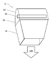
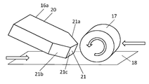
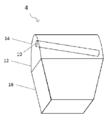
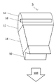
도 1은 본 발명의 실시예에 따른 장치(1)를 도시한다. 장치(1)는 펄스화된 광대역 방사선 소스(10) 및 광 가이드(12)를 포함한다. 광 가이드(12)는, 타겟 영역에 대해, 펄스화된 광대역 방사선 소스(10) 뒤쪽에 있는 제1 부분(14), 및 펄스화된 광대역 방사선 소스(10) 앞쪽에 있는 제2 부분(16)을 포함하며, 이는 화살표(100)의 일반적인 방향으로 있다. 타겟 영역은 본 발명의 파트(part)를 형성하지 않는다.Figure 1 shows an
일부 실시예에서, 광 가이드(12)의 제1 부분(14) 및 제2 부분(16)은 동일한 파트에 포함된다. 예를 들어, 광 가이드(12)는 단일 시트(single sheet)로부터 형성될 수 있다. 다른 실시예에서, 광 가이드(12)는 복수의 파트들로부터 형성될 수 있으며, 이들 중 적어도 일부는 함께 고정되거나 및/또는 다른 방식으로 연결 및/또는 결합된다. 또 다른 실시예에서, 광 가이드는 타겟 영역에 대해 광대역 방사선 소스의 앞쪽(front) 또는 뒤쪽(behind)에 있는 일 부분만을 포함할 수 있다. 그 부분은 함께 고정 및/또는 다른 방식으로 연결 및/또는 결합되는 하나 이상의 파트들을 포함할 수 있다.In some embodiments, the
일부 실시예에서, 도 1의 장치는 복합 재료로부터의 복합물을 제조하기 위한 장치이다.In some embodiments, the apparatus of Figure 1 is an apparatus for manufacturing a composite from a composite material.
광 가이드(12)의 제1 부분(14)은 펄스 광대역 방사선 소스(10)에 의해 광 가이드(12)의 제2 부분(16)을 향해 방출된 방사선을 반사시키도록 구성되고 배열된다. 일부 실시예들에서, 광 가이드(12)의 제1 부분(14)은 내부 표면에 광-반사성 코팅(light-reflective coating)을 포함한다. 광-반사 코팅은 반사될 파장을 선택할 수 있거나 파장의 광범위한 범위를 반사시킬 수 있다.The
본원에 사용된 바와 같이, 본 명세서 전체에 걸쳐, 광-반사성 코팅은 다음과 같은 방식으로 정의될 수 있다. 이 목록은 독점적인 것이 아니며, 광-반사성 코팅들의 다른 형태들도 적합할 수 있다. 확산 재료는 반사기(reflector)를 형성하기 위해 장치(1)의 표면 상에 증착될(deposited) 수 있다. 금속 재료는 반사기를 형성하기 위해 장치(1)의 표면 상에 증착될 수 있다. 적합한 금속 재료들의 예시들은 금(gold), 알루미늄(aluminium), 은(silver), 강철(steel) 또는 기타 등등을 포함한다. 대안적으로, 또는 부가적으로, 비금속성, 반사 재료(non-metallic, reflective material)는 반사기를 형성하기 위해 장치(1)의 표면 상에 증착될 수 있다. 반사성 재료는 장치(1)의 표면의 형상으로 모듈화되고(moulded), 그 표면에 부착되어(affixed) 반사기를 형성할 수 있다. 반사기는 영구적으로 또는 제거 가능하게 또는 이동 가능하게 장치에 부착될 수 있다. 일부 실시예들에서, 반사기는 특정 방식으로 광을 추가로 지향시키는(direct) 패턴(pattern)을 포함할 수 있다.As used herein, throughout this specification, a light-reflective coating may be defined in the following manner. This list is not exclusive and other forms of light-reflective coatings may be suitable. The diffusing material may be deposited on the surface of the
일부 실시예들에서, 광 가이드(12)의 제1 부분(14)은 펄스화된 광대역 방사선 소스(10)에 및/또는 광 가이드(12)의 제2 부분(16)에 대해 이동 가능하도록 구성된다. 예를 들어, 제1 부분(14)은 변형 가능하거나(deformable), 서로에 관해 이동 가능한 다수의 기계적으로-연결된 세그먼트들(mechanically-linked segments)을 포함하거나, 또는 펄스화된 광대역 방사선 소스(10)에 및/또는 광 가이드(12)의 제1 부분(14)에 대해 임의의 다른 방식으로 이동 가능하다. 광 가이드(12)의 제1 부분(14)의 이러한 이동은, 장치에 의해 착수되는(undertaken) 특정 공정에 의해 요구되는 바와 같이, 미리 결정된 강도 또는 입사각으로 광 가이드(12)의 제2 부분(16)을 향해 반사되는, 펄스화된 광대역 방사선 소스(10)에 의해 방출된 방사선을 초래할 수 있다. 일부 실시예들에서, 펄스화된 광대역 방사선 소스(10)에 및/또는 광 가이드(12)의 제2 부분(16)에 대한 광 가이드(12)의 제1 부분(14)의 이러한 이동은, 이제부터 더 상세하게 설명되는 바와 같이, 장치의 작동 동안 발생할 수 있다.In some embodiments, the
일부 실시예들에서, 광 가이드(12)의 제2 부분은 펄스화된 광대역 방사선 소스(10)에 및/또는 광 가이드(12)의 제2 부분(16)에 대해 이동 가능하도록 구성된다. 예를 들어, 제2 부분(16)은 변형 가능하거나, 서로에 관해 이동 가능한 다수의 기계적으로-연결된 세그먼트들(mechanically-linked segments)을 포함하거나, 또는 펄스화된 광대역 방사선 소스(10)에 및/또는 광 가이드(12)의 제1 부분(14)에 대해 임의의 다른 방식으로 이동 가능하다. 광 가이드(12)의 제2 부분(16)의 이러한 이동은 타겟 영역에서 방사선 프로파일의 형성 또는 변화를 초래할 수 있다. 일부 실시예들에서, 펄스화된 광대역 방사선 소스(10)에 및/또는 광 가이드(12)의 제1 부분(14)에 대한 광 가이드(12)의 제2 부분(16)의 이러한 이동은, 이제부터 더 상세하게 설명되는 바와 같이, 장치의 작동 동안 발생할 수 있다.In some embodiments, the second portion of the
일부 실시예들에서, 광 가이드(12)는 펄스화된 광대역 방사선 소스(10)에 의해 방출된 파장의 범위 또는 특정 파장의 방사선을 가이드한다. 예를 들어, 광 가이드(12)는 적외선 파장을 통과시킬(transparent) 수 있지만, 가시 스펙트럼(visible spectrum)에서의 광을 반사시킬 수 있다. 광 가이드(12)의 구성 요소(composition)는 장치(1)가 구성되는 공정, 및 따라서 타겟 영역에서 요구된 파장에 기초하여 선택된다.In some embodiments, the
일부 실시예들에서, 펄스화된 광대역 방사선 소스(10)는 복합 재료들을 가열하는데 사용된다. 일부 실시예들에서, 장치(1)는 30과 600 섭씨온도 사이의 온도로 타겟 영역에 재료를 가열하도록 배열된다. 예를 들어, 열경화성 재료들(thermoset materials)의 경우, 온도 범위는 30과 150도 사이일 수 있다. 건조 섬유 재료들(dry fibre materials)의 경우, 온도 범위는 70과 300도 사이일 수 있다. 열가소성 재료들(thermoplastic materials)의 경우, 범위는 70과 600도 사이일 수 있다. 장치(1)의 다른 애플리케이션들에서, 타겟 영역에서 요구되는 온도는 이 범위를 벗어날 수 있고, 예를 들어 20과 1000섭씨온도 사이일 수 있다. 당업자는, 명세서 개시 및 그 또는 그녀의 애플리케이션(his or her application)의 파라미터들에 대한 이해에 기초하여, 적절한 온도 프로파일 및/또는 범위를 선택할 수 있을 것이다.In some embodiments, the pulsed
일부 실시예들에서, 펄스화된 광대역 방사선 소스의 펄스 당 방출된 에너지의 양은 50과 10,000 줄(Joules) 사이의/보다 더 클 수 있고(greater than/between 50 and 10,000 Joules), 펄스화된 광대역 방사선 소스에 의해 방출된 평균 전력(average power)은 50W와 32,000W 사이일 수 있다.In some embodiments, the amount of energy emitted per pulse of the pulsed broadband radiation source may be greater than / between 50 and 10,000 Joules and between 50 and 10,000 Joules, the pulsed broadband The average power emitted by the radiation source may be between 50W and 32,000W.
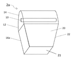
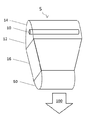
도 2a-도 2g는 본 발명의 다른 실시예를 도시한다. 장치(2a)는 장치(1)와 실질적으로 유사하고, 유사하게 번호가 매겨진 동일한 특징들(similarly-numbered features that are the same)은 다시 설명되지 않을 것이다. 도 2a에 따르면, 장치(2a)의 광 가이드(12)의 제2 부분(16a)은 광 투과성 재료의 블록(block)(20)을 포함한다. 블록(20)은 석영, 용융 실리카(fused silica), BK7, KG3, 파이렉스(Pyrex), 소다 유리(Soda glass), 로박스(Robax), 또는 임의의 다른 적절한 광 투과성 재료 중 적어도 하나를 포함할 수 있다. 일부 실시예들에서, 블록(20)은, 예를 들어 광 투과성 재료를 포함하는 지지 구조체(supporting structure) 또는 성형된 컨테이너(shaped container) 내에 광 투과성 재료의 액체 또는 겔(gel)을 포함할 수 있다. 일부 실시예들에서, 지지 구조체 또는 성형된 컨테이너는 대안적으로(alternatively) 펄스화된 광대역 방사선 소스(10)에 의해 방출된 광(또는 적어도 광 또는 방사선의 요소들)을 투과시키는 가스(gas)를 포함할 수 있다. 광 투과성 재료의 블록(20)은 타겟 영역에 광을 전달할 수 있는 임의의 형상일 수 있다. 예를 들어, 블록(20)의 기하학적 구조(geometry)는 블록의 측벽들(도 2a에서 4 개가 있음), 또는 더 구체적으로는 그 내부 표면들이, 예를 들어 펄스화된 광대역 방사선 소스(10)에 의해 방출 및 수신된(received) 광의 내부 반사(internal reflection)에 의해, 반사기(reflectors)로서 일반적으로 작용하도록 배열될 수 있다. 블록(20) 내의 예리한 내부 반사 각도는 펄스화된 광대역 방사선 소스(10)로부터의 광이 벽의 내부 표면들로부터 블록(20)으로 그리고 일반적으로 타겟 영역을 향해 반사되도록 유발한다(cause). 대조적으로, 펄스화된 광대역 방사선 소스(10)에 더 가까운 입력 단, 면 또는 표면(input end, face or surface), 및 펄스화된 광대역 방사선 소스(10)로부터 더 먼(그리고 타겟 영역에 가장 가까운) 출력 단, 면 또는 표면(output end, face or surface)(21)은 펄스화된 광대역 방사선 소스(10)에 의해 방출 및 수신되는 광을 반사하는 대신 투과시킨다. 직접적으로 펄스화된 광대역 방사선 소스(10)로부터의(또는 간접적으로 벽의 내부 표면들로부터의 하나 이상의 반사들을 통한 펄스화된 광대역 방사선 소스(10)로부터의) 광은 출력 표면(output surface)(21)에 예각으로 부딪히지(impinge) 않고, 따라서 출력 표면(21)을 통해 그리고 타겟 영역을 향해 블록(20)을 나갈(exit) 수 있다. 출력 광의 형태 또는 프로파일은 출력 단, 면 또는 표면(21)의 형태에 의해 크게 영향을 받는다.Figures 2A-2G illustrate another embodiment of the present invention. The device 2a is substantially similar to the
사실상, 블록(20)은 광 가이드(16a)의 제2 부분을 나온 광을, 출력 표면(21)을 통해, 타겟 영역을 향하는 방향으로, 포커싱 및/또는 집중시킨다. 도 2a의 출력 표면(21)은 플랫하고, 평평한 표면(flat, planar surface)을 포함하며, 이는 펄스화된 광대역 방사선 소스(10)의 종축(longitudinal axis)에 일반적으로 평행하고, 블록(20)을 나오는 광의 방향에 일반적으로 수직인 것으로 도시된다. 일부 실시예들에서, 블록(20)의 출력 표면(21)의 형상은 타겟 영역에서 요구되는 방사선 프로파일을 전달하도록 배열되며, 그 예시는도 2b-g에 도시된다.In fact, the
일부 실시예들에서, 사용시, 블록(20)은 펄스화된 광대역 소스(10)로부터 타겟 영역으로 실질적으로 연장한다. 일부 실시예들에서, 사용시, 블록(20)의 출력 표면(21)은 타겟 영역과 접촉하지 않지만, 다른 실시예들에서는 접촉한다.In some embodiments, in use, the
일부 실시예들에서, 블록(20)의 하나 이상의 표면들은, 예를 들어 광을 블록 내에 가두도록(confine) 배열된, 광 반사성 코팅(light reflective coating)(22)을 포함한다. 예를 들어, 이것은 내부 반사를 증가시켜, (예컨대, 블록에서의 내부 및/또는 표면 결함들(internal and/or surface imperfections) 또는 블록의 표면에서의 잔해(debris)로부터 생성된 산란(scattering)으로 인한) 블록의 사이드들로부터의 빛 누출(light leakage)을 감소시키고, 및/또는, 일반적으로, 타겟 영역에 증가된 광을 전달할 수 있다. 일부 실시예들에서, 광이 광 가이드(12)의 제1 부분(14)으로부터 블록으로 들어가는(enters) 입력 표면(input surface) 및 광이 타겟 영역을 향해 블록(20)을 나오는 출력 표면(21)을 제외한, 블록(20)의 각각의 표면들은 광 반사성 코팅(22)을 포함할 수 있다. 광 반사성 코팅(22)은 광을 다시 블록(20)으로 반사시킴으로써 장치(2a)의 효율성을 증가시킬 수 있으며, 이는 그렇지 않으면 블록(20)의 벽을 통해 타겟 영역으로부터 멀어지는 방향으로 나왔을 것이다.In some embodiments, one or more surfaces of the
일부 실시예들에서, 광 반사성 코팅(22)은 장치(2a)가 구성되는 공정에서 요구되지 않는 펄스화된 광대역 방사선 소스(10)에 의해 방출된 파장을 실질적으로 통과시킨다. 일부 실시예들에서, 예를 들어, 장치(2a)가 복합 재료로부터의 복합 물품의 제조에 사용될 때, 블록(20)은, 예를 들어, 적외선 파장(infrared wavelengths)과 같은, 복합 재료를 가열시키는 펄스화된 광대역 방사선 소스(10)에 의해 방출된 광의 파장을 고도로(highly) 투과시킨다(transmissive). 일부 실시예들에서, 블록(20)은 UV 파장을 고도로 투과시킬 수 있으며, 예를 들어, 애플리케이션은 경화 애플리케이션(curing application)이다. In some embodiments, the light
일부 실시예들에서, 블록(20)은 400nm와 1mm 사이의 파장을 고도로 투과시킨다. 일부 실시예들에서, 블록(20)은 700nm와 1mm 사이의 파장을 고도로 투과시킨다.In some embodiments, the
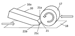
도 2b-도 2g는 복합 재료로부터의 복합 물품의 제조를 위한 자동화된 섬유 배치(automated fibre placement)에 사용되는 장치(2a)의 블록(20)의 예시들을 도시한다. 각각의 예시에서, 블록(20)의 형상 및 기하학적 구조는 타겟 영역에서 요구되는 방사선 프로파일에 기초하여 선택된다. 블록(20)의 출력 표면은 광이 원하는 방사선 프로파일로 타겟 영역으로 광 가이드(16a)의 제2 부분을 나오도록, 형상화(shaped), 패시트(faceted) 또는 멀티-패시트(multi-faceted) 될 수 있다. 타겟 영역은 기하학적으로 복잡할 수 있으며, 예를 들어 하나의 형상화된 영역 또는 하나 이상의 영역을 포함할 수 있다. 타겟 영역의 복수의 영역들이 있는 경우, 각각의 영역은 하나의 평면 또는 하나 이상의 평면에 존재(reside)할 수 있다. 예를 들어, 타겟 영역은 동일한 물체(same object)의 하나 이상의 영역들 또는 복수의 상이한 물체에 놓일 수 있다. 일부 실시예들에서, 형상화 또는 패시트된 리딩 표면(shaped or faceted leading surface)(21)은 타겟 영역을 향하는 방향으로 광 가이드(16a)의 제2 부분을 나가는 광을 포커싱 및/또는 집중시킨다. 블록(20)은 블록(20)이 사용시에 타겟 영역에 더 가깝게 위치될 수 있도록 형상화 될 수 있다. 예를 들어, 블록(20)은 원하는 타겟 영역에 더 근접하기 위해 한정된 공간 또는 체적(confined space or volume) 내에 끼워지도록 형상화 될 수 있다. 일부 예시들에서, 복합 제조와 관련하여, 타겟 영역은 압축 롤러(compaction roller)(17)의 적어도 일 부분 및 기판 표면(substrate surface)(18)의 적어도 일 부분 중 하나 또는 둘 모두를 포함할 수 있다.Figures 2B-2G illustrate examples of
도 2b는 중앙, 전방-대면 표면(central, forward-facing surface)(21c)을 통해 결합된, 인접하고 대칭인 상부 및 하부 챔퍼된 표면들 또는 패시트들(adjoining, symmetrical upper and lower chamfered surfaces or facets)(21a, 21b)을 포함하는 대칭 챔퍼된 블록(symmetrically chamfered block)(20)을 도시한다. 이 예시에서, 단지 편의를 위해, 광 가이드(12)의 제1 부분(14) 및 펄스화된 광대역 방사선 소스(10)는 도시되지 않는다. 블록(20)은 예시적인 복합 제조 공정에서 압축 롤러(17) 및 기판 표면(18)에 대해 배열되고 배치된다. 도 2a의 화살표 A, L, R은 압축 롤러(17)의 회전의 방향 및 압축 롤러(17)와 기판 표면(18)의 상대 이동을 나타낸다. 기판 표면(18), 압축 롤러(17), 또는 둘 모두는, 각각의 화살표에 의해 도시된 바와 같이 서로에 대해 수평으로 병진 이동(translate)하도록 배열될 수 있다.FIG. 2B illustrates a top view of adjacent and symmetrical upper and lower chamfered surfaces or facets (adjoining, symmetrical upper and lower chamfered surfaces or) joined through a central, forward-facing
도 2b에 도시된 바와 같이, 전방-대면 표면(21c)을 나가는 광이 압축 롤러(17)가 기판 표면(18)과 접촉하게 되는 닙 포인트(nip point)(17a)를 포함하는(encompassing) 타겟 영역의 제1 영역에 부딪히도록, 블록(20)은 배열되고 배치된다. 압축 롤러(17)는 기판 표면(18)에 압력을 가하거나 기판 표면(18) 상에 새로운 재료를 가이드하는데 사용될 수 있으며, 따라서 타겟 영역의 제1 영역은 압축 롤러(17)의 외부 표면, 또는 기판(18)에 추가될 압축 롤러(17)의 외부 표면에서의 새로운 재료의 층(layer)일 수 있다. 상부 챔퍼된 표면(upper chamfered surface)(21a)을 통해 나오는 광은 닙 포인트(17a)보다 먼저 압축 롤러(17)의 리딩 면(leading face)을 포함하는 목표 영역의 제2 영역에 부딪힌다. 하부 챔퍼된 표면(lower chamfered surface)(21c)을 나가는 광은 닙 포인트(17a)보다 먼저 기판 표면(18)의 일 부분을 포함하는 타겟 영역의 제3 영역에 부딪힌다. 블록(20)의 3개의 전술한 패시트들로부터 빠져나오는(emerging) 광의 일반적인 방향은 평행한 화살표를 사용하여 그림으로 표시된다. 이러한 방식으로, 압축 롤러(17) 및 기판 표면(18)은 전방-대면 표면(21c)을 통해 방출된 방사선에 의해 닙 포인트(17a)에서 추가로 가열되기 전에, 챔퍼된 표면(21a, 21b)을 통해 방출된 방사선에 의해 예열된다(pre-heated).2b, the light exiting the front-facing
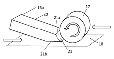
일부 실시예들에서, 블록(20)은 타겟 영역의 각각의 영역 또는 영역들에 실질적으로 평행하게 배열되는 챔퍼들(chamfers)(21a, 21b)을 포함할 수 있다. 도 2c는 압축 롤러(17)의 표면에 실질적으로 평행한(즉, 접선의(tangential to)) 챔퍼(21a) 및 기판 표면(18)에 실질적으로 평행한 챔퍼(21b)를 도시한다. 챔퍼들(21a, 21b)의 전체 표면 영역들이 타겟 영역의 각각의 영역들에 더 가깝게 위치될 수 있는 능력(ability)에 의해, 이 구성은 비-평행한 배열(non-parallel arrangement)에 비해 타겟 영역의 각각의 영역들에서 방사선 강도를 증가시킬 수 있다.In some embodiments, the
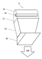
도 2d는 단일의, 플랫한 챔퍼된 패시트 또는 표면(single, flat chamfered facet or surface)(21b) 및 인접한, 플랫한 전방-대면 패시트 또는 표면(adjoining, flat forward-facing facet or surface)(21c)을 포함하는 출력 표면(21)을 갖는 블록(20)을 도시한다. 이 배열은 닙 포인트를 가열하고, 기판 표면(18)을 예열하지만 압축 롤러(17)는 예열하지 않는다.Figure 2d illustrates a single, flat chamfered facet or
도 2e는 압축 롤러(17)의 반경과 실질적으로 유사한 곡률 반경(radius of curvature)을 갖는, 곡선의 오목 챔퍼(curved concave chamfer)(21a), 및 기판 표면(18)에 실질적으로 평행한, 플랫하고, 평평한 챔퍼(flat, planar chamfer)(21b)를 포함하는 출력 표면(21)을 갖는 블록(20)을 도시한다. 이 배열은 압축 롤러(17)의 곡선의 표면(curved surface)의 더-효율적인 예열(more-efficient pre-heating)을 제공한다.Figure 2e shows a curved
도 2f는 일반적으로 오목한 전방-대면 출력 표면을 형성하는, 2 개의 인접한 좌우의 플랫한 챔퍼된 패시트들(two adjoining left and right flat chamfered facets)(21a, 21b) 및 플랫한, 전방-대면 패시트(flat, forward-facing facet)(21c)를 포함하는 리딩 표면(21)을 갖는 블록(20)을 도시한다. 이러한 배열은 닙 포인트 보다 바로 먼저 기판 표면(18) 및 압축 롤러(17)의 닙 포인트 및 영역들을 포함하는 타겟 영역에 부딪히는 광 방사선을 강화시킨다(intensifies). 부가적으로, 또는 대안적으로, 다른 실시예들에서, 오목한 배열은 블록(20)의 출력 표면(21)이 볼록한 타겟 영역(convex target area), 또는 예를 들어 볼록한 물체(convex object) 또는 기판 표면(substrate surface)에 더 효율적으로 광을 방출하게 할 수 있다.Figure 2f shows two adjoining left and right flat
도 2g는 중심 전방-대면 표면(21c)을 통해 결합되고 일반적으로 볼록한 전방-대향 출력 표면을 형성하는, 2개의 인접한, 좌우 대칭인 챔퍼된 표면들(two adjoining, left and right symmetrical chamfered surfaces)(21a, 21b)을 포함하는 대칭으로 챔퍼된 리딩 표면(21)을 갖는 블록(20)을 도시한다. 챔퍼된 표면들(21a, 21b)의 배열은, 블록의 앞쪽에서, 블록(20)의 폭보다 광을 넓게 퍼지게 한다. 부가적으로 또는 대안적으로, 다른 실시예들에서, 볼록한 전방-대향 출력 표면은 오목한 타겟 영역으로, 예를 들어 오목한 물체 또는 기판 표면(18)으로의 광의 더 효율적인 전달을 가능하게 할 수 있다.FIG. 2G shows two adjoining, left and right symmetrical chamfered surfaces (FIG. 2B) joined through the central front-facing
도 2b-도 2g는 단지 예시로서 도시된다. 블록의 벽들 및 표면들의 다른 기하학적 구조들 및 배열들은 대안적으로 타겟 영역의 모든 형태들에 적합하도록 설계될 수 있다. 이러한 블록은 각각의 타겟 영역에 원하는 방사선 프로파일을 갖는 광을 전달하는데 적합한 임의의 형상을 포함할 수 있으며, 이는 기하학적으로 복잡하고 및/또는 하나 이상의 영역들을 포함할 수 있다.2B-2G are shown by way of example only. Other geometries and arrangements of walls and surfaces of the block may alternatively be designed to suit all shapes of the target area. Such a block may include any shape suitable for transmitting light having a desired radiation profile in each of the target regions, which may be geometrically complex and / or comprise one or more regions.
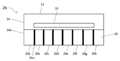
도 3은 본 발명의 실시예들에 따른 장치(2b)를 도시한다. 도 3은 광 투과성 재료의 블록(20)이 광 투과 재료의 2 개 이상의 세그먼트들(segments)을 포함하는, 장치(2b)의 대안적인 배열이다. 이 예시에서, 8 개의 이러한 세그먼트들(20a-h)이 도시된다. 일부 실시예들에서, 각 세그먼트(20a-h)는 장벽(barrier)(20a1)에 의해 분리될 수 있다. 일부 실시예들에서, 장벽은 공기(air)일 수 있다. 다른 실시예들에서, 장벽은 각각의 이웃한 세그먼트들(respective, neighbouring segments)의 하나 또는 각각의 중간 표면(one or each intermediate surface)에서의 반사기 또는 광 반사 코팅일 수 있다. 2 개 이상의 세그먼트들(20a-h)을 포함하는 블록은 타겟 영역에서 더 균일한 방사선 프로파일을 생성할 수 있다. 광 가이드(12)의 제2 부분(16a)을 통해 가이드되는 광은 타겟 영역을 향한 더 선형적인 경로(more linear path)를 따라가는 것으로 예상된다.Figure 3 shows a
일부 실시예들에서, 세그먼트들(20a-h)이 겔 또는 액체를 포함하며, 세그먼트들을 분리하는 하나 이상의 장벽들은 이동 또는 변형되도록 구성될 수 있으며, 따라서 각각의 세그먼트들(20a-h)의 형상을 변화시킨다. 일부 실시예들에서, 세그먼트들(20a-h) 중 하나 이상은 타겟 영역에 더 가깝게 또는 더 멀어지도록 이동하거나, 장치(2b)의 작동 동안 변형되도록 구성될 수 있다.Hi some embodiments, the
일부 실시예들에서, 2 개 이상의 세그먼트들(20a-h)을 포함하는 블록(20)은, 예를 들어 도 2b-도 2f에 도시된 바와 같이, 형상화, 패시트 또는 챔퍼 될 수 있다.In some embodiments, the
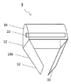
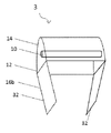
도 4는 본 발명의 실시예들에 따른 장치를 도시한다. 장치(4)는 도 1의 장치와 실질적으로 유사하고, 장치(3)의 광 가이드(12)의 제2 부분(16b)은 중공 도파관(hollow waveguide)(30)을 포함한다. 중공 도파관(30)은 적어도 하나의 광 반사성 벽(32)을 포함한다. 일부 실시예들에서, 중공 도파관(30)은 복수의 광 반사성 벽들(light reflective walls)(32)을 포함한다. 일부 실시예들에서, 광 반사성 벽(들)(32)은 장치(3)가 구성된 공정에 대해 요구되지 않은 펄스화된 광대역 방사선 소스(10)에 의해 방출된 파장을 통과시킨다(transparent). 일부 실시예들에서, 광 가이드(12)의 제2 부분(16b)은 도 2a-도 2g를 참조하여 설명된 바와 같이, 중공 도파관(30) 및 광 투과성 재료의 블록을 포함할 수 있다. 광 투과성 재료의 블록은 중공 도파관(30)보다 타겟 영역에 더 가깝거나, 그 반대일 수 있다.Figure 4 illustrates an apparatus according to embodiments of the present invention. The
일부 실시예들에서, 적어도 하나의 광 반사성 벽(32)은 폐쇄된 단면(closed cross-section)을 형성하여, 펄스화된 광대역 방사선 소스(10)에 의해 방출된 광이 적어도 하나의 광 반사성 벽(32)에 의해 형성된 광 가이드(12)의 제2 부분(16b)의 사이드들(sides)로부터 벗어나올(escape) 수 없게 한다. 이는 개방 단면(open cross-section)과 비교하여 타겟 영역에서 방사선 강도를 증가시킬 수 있다. 폐쇄된 단면의 형상은 타겟 영역에서 요구되는 방사선 프로파일을 제공할 수 있는 임의의 형상일 수 있다. 다른 실시예들에서, 광 반사성 벽들(32)은 폐쇄된 단면을 형성하지 않는다.In some embodiments, at least one light
도 5a-도 5c는 본 발명의 장치(3)에 따른 일 실시예의 도면을 도시한다. 중공 도파관(30)의 전방 및 후방 벽들(front and rear walls)(32)은 명료성을 위해 도시되지 않았다. 사실, 다른 실시예들에서, 장치(3)는 전방 및 후방 벽들(front and rear walls)(32)을 포함하지 않는다. 다른 실시예들에서, 벽들(32)은 임의의 다른 적절한 배열로 구성되어, 벽이 개별적으로 또는 함께 칸막이들(baffles) 또는 블링커들(binkles)로서 작용하여 방출된 광의 형성 또는 프로파일을 가이드 및/또는 조절하도록(tune) 할 수 있다. 본 발명의 이러한 실시예들에 따르면, 중공 도파관(30)의 광 반사성 벽들(32) 중 적어도 하나는 다른 것(들)에 대해 이동 가능하다. 벽(32) 또는 각각의 벽(32)의 이동은 타겟 영역에서 방사선 프로파일의 미리 결정된 변화를 초래한다. 일부 실시예들에서, 벽들(32)은, 예를 들어 힌지 장치(hinge arrangement) 등을 포함하는 축을 중심으로 회전한다(rotate). 다른 실시예들에서, 하나 이상의 벽들(32)은 변형 가능하다(deformable). 다른 실시예들에서, 하나 이상의 벽들(32)은 다른 것(들)에 대해 임의의 다른 방식으로 이동 가능하다.Figures 5A-5C show a view of an embodiment according to the
도 6a-도 6c는 본 발명에 따른 실시예들의 도면들을 도시한다. 장치(4)는 도 1-5를 참조하여 상기 설명된 임의의 장치와 실질적으로 유사할 수 있으며, 단독으로 또는 그의 임의의 특징들과 함께 조합되어 사용될 수 있다. 장치(4)의 펄스화된 광대역 방사선 소스(10)는 광 가이드(12)에 대해 이동 가능하도록 구성된다. 일부 실시예들에서, 펄스화된 광대역 방사선 소스(10)는 장치(4)의 작동 동안 광 가이드(12)에 대해 이동 가능하도록 구성 가능하다.Figures 6A-6C illustrate views of embodiments according to the present invention. The
일부 실시예들에서, 펄스화된 광대역 방사선 소스(10)는 광 가이드(12)의 제1 부분(14) 내에서 병진 이동하도록 장착(mounted) 및/또는 구성되어, 예를 들어 소스의 종축의 지향(orientation)이 광 가이드(12)의 지향에 대해(relative to) 일정하게 유지되도록 한다. 일부 실시예들에서, 펄스화된 광대역 방사선 소스(10)는 광 가이드(12)에 대해 기울어지거나(tilt) 회전하도록 장착 및/또는 구성되어, 예를 들어, 소스의 종축의 지향이 광 가이드(12)의 지향에 대해 변화하도록 한다. 예를 들어, 펄스화된 광대역 방사선 소스(10)는, 제1 단부가 하나의 방향으로 이동될 수 있도록 구성되는 반면, 제2 단부는 고정된 상태로 유지되거나, 제2 단부는 상이한 방향으로 이동될 수 있거나, 제2 단부는 제1 단부에 대해 상이한 양이지만, 동일한 방향으로 이동될 수 있다.In some embodiments, the pulsed
일부 실시예들에서, 예를 들어 장치(4)에 따르면, 더 일반적으로는, 펄스화된 광대역 방사선 소스(10) 및 광 가이드(12)의 적어도 일 부분(14, 16)은 서로에 대해 이동 가능하다. 실제로, 하나 이상의 방사선 소스가 있을 수 있고, 하나 이상의 소스들 및 광 가이드는 서로에 대해 이동 가능할 수 있다.In some embodiments, for example, according to
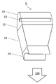
도 7a-도 7f는 본 발명에 따른 실시예들의 도면들을 도시한다. 장치(5)는 도 1-도 6을 참조하여 상기 설명된 임의의 장치와 실질적으로 유사할 수 있으며, 단독으로 또는 그의 임의의 특징들과 조합하여 사용될 수 있다. 특히, 광 가이드의 제2 부분은 광 투과성 재료의 블록을 포함할 수 있고 및/또는 중공 도파관을 포함할 수 있다. 어떤 경우에서나, 광 가이드(12)의 제2 부분은 형상화된 렌즈(shaped lens)(50)에 의해 증대된다(augmented). 일부 실시예들에서, 형상화된 렌즈(50)는 광 가이드의 제1 부분(14)과 제2 부분(16) 사이에 있을 수 있다(도시 생략). 다른 실시예들에서, 형상화된 렌즈(50)는 광 가이드(12)의 제2 부분(16)의 임의의 다른 포인트에 있을 수 있다.Figures 7A-7F illustrate views of embodiments according to the present invention. The
일부 실시예들에서, 형상화된 렌즈(50)는, 화살표(100)의 일반적인 방향인, 타겟 영역을 향하는 방향으로 광 가이드(16)의 제2 부분을 나가는 광을 형상화, 포커싱 및/또는 집중시킨다. 다른 실시예들에서, 형상화된 렌즈(50)는 광 가이드(16)의 제2 부분을 나가는 광을 굴절시킨다(refracts). 형상화된 렌즈(50)는 원하는 방사선 프로파일을 갖는 광을 타겟 영역에 전달하는데 적합한 임의의 형상을 포함할 수 있다. 형상화된 렌즈(50)의 형상들의 대안적인 예시들은 도 7a-f에 도시되어 있다. 도 7a는 볼록한 출력 면(convex output face)을 포함하는 볼록 렌즈 (50)를 도시하며, 이는 타겟 영역 위로 빛을 고르게 분포시킬 수 있다. 도 7b는 2 개의 출력 면들 또는 패시트들을 포함하는 프리즘형 렌즈(prism-like lens)(50)를 도시하며, 이는 각 면 또는 패시트 사이에서 광 가이드(12)를 나가는 광을 분리할 수 있다. 도 7c는 렌즈의 출력 면을 형성하는 베이스(base)를 갖는 사다리꼴 렌즈(trapezoidal lens)를 도시하며, 이는 광 가이드(16)의 출력 면의 유효 크기를 증가시키고, 렌즈가 없는 광 가이드(12)의 크기보다 더 큰 영역에 광을 분배할 수 있다. 도 7d는 오목 렌즈(50)를 도시하며, 이는 광 가이드(12)의 크기보다 더 작은 영역으로 광을 포커싱할 수 있다. 도 7e는 일반적으로 오목한 출력 면을 형성하는 2 개의 출력 패시트들을 갖는 다각형 렌즈(polygonal lens)(50)를 도시하며, 이는 타겟 영역에서의 복수의 위치들에 광을 지향시킬 수 있다. 도 7f는 도 7e의 출력 면과 유사하지만 더 큰 출력 면을 갖는 y-형 렌즈(y-shaped lens)(50)를 도시하며, 이는 특정 영역에 광을 강하게 포커싱 할 수 있다.In some embodiments, the shaped
일부 실시예들에서, 형상화된 렌즈는 원하는 목적에 따라 분리 가능하고 및/또는 교환 가능할 수 있다. 요구되는 특정 렌즈(50)는 타겟 영역에서 요구된 방사선 프로파일에 기초하여 선택된다.In some embodiments, the shaped lens may be separable and / or interchangeable depending on the desired purpose. The
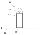
도 8은 본 발명의 실시예들에 따른 장치(6)를 도시한다. 장치(6)는 본 명세서에서 도 1 내지 도 7 중 어느 하나를 참조하여 설명된 바와 같은 장치를 포함할 수 있고, 접촉 표면(contact surface)(60)을 포함하도록 추가적으로 구성된다. 접촉 표면(60)은, 물체(62)의 접촉 영역(contact region)에, 예를 들어 압력을 가하기 위하여, 접촉하여 배치될 수 있다. 이러한 방식으로, 본 장치는, 예를 들어, 결합 작업(bonding operation)을 지원하거나 완료하기 위해, 물체를 가열하고 동시에 또는 순차적으로, 물체에 압력을 가하는데 사용될 수 있다. 일부 실시예들에서, 접촉 영역은 타겟 영역에 또는 근처에 있다. 일부 실시예들에서, 타겟 영역은 물체(62)에 있다.Figure 8 shows a
일부 실시예들에서, 물체(62)의 접촉 영역은 타겟 영역과 실질적으로 일치한다. 다른 실시예들에서, 접촉 영역은 타겟 영역의 일 부분과 실질적으로 일치, 및/또는 겹친다(overlaps). 다른 실시예들에서, 접촉 영역은 타겟 영역을 둘러싸고 있다(surrounds). 예를 들어, 접촉 영역은 그 중심 또는 그 근처에 있는 타겟 영역을 갖는 고리(annulus)일 수 있다. 다른 실시예들에서, 접촉 영역은 타겟 영역에 인접하여, 영역이 장치(6)에 의해 조사된 후에 압력은 물체(62)의 접촉 영역에 가해지도록 한다.In some embodiments, the contact area of the
일부 실시예들에서, 예를 들어, 복합 물품으로 복합 재료의 층들을 가열 및 부착시키기(adhere) 위해, 장치(6)는 복합물의 열 처리의 사용을 위해 구성된다. 물체(62)는 펄스화된 광대역 방사선 소스(10)에 의해 가열될 수 있는 복합 재료의 층들을 포함하는 복합물일 수 있다. 접촉 표면(60)은 타겟 영역의 가열 전에, 동안에 및/또는 후에 물체(62)의 접촉 영역을 압축하기 위하여 복합물에 압력을 가하도록 구성되어서, 물체(62) 내의 복합 재료의 층들이 가열되거나 또는 여전히 고온인 상태에서 함께 접착될(tacked) 수 있다. 일부 실시예들에서, 물체(62)의 특정 영역들만이 접착된다.In some embodiments, for example, to heat and adhere the layers of composite material to a composite article, the
일부 실시예들에서, 접촉 표면(60)은 광 가이드(12)의 제2 부분(16)과 일체화된다(integral). 일부 실시예들에서, 예를 들어, 장치(6)의 광 가이드(12)의 제2 부분(16)은 광 투과성 재료의 블록(20)을 포함하며, 접촉 표면(60)은 블록(20)의 출력 표면(21)이다. 블록(20)의 출력 표면은 도 2b-g에 도시된 예시들인, 형상화된 및/또는 패시트된 리딩 표면(21)일 수 있다.In some embodiments, the
일부 실시예들에서, 접촉 표면(60)은 도 7a-f에 도시된 바와 같은 형상화된 렌즈(50)에 포함된다.In some embodiments, the
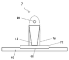
도 9는 본 발명의 실시예에 따른 장치(7)를 도시한다. 장치(7)는 도 1 내지 도 7 중 어느 하나를 참조하여 설명된 장치, 접촉 표면(60) 및 지지 프레임(support frame)(70)을 포함할 수 있다. 접촉 표면(60)은 물체(62)의 접촉 영역에 장치(7)에 의해 압력을 가하도록 구성된다. 일부 실시예들에서, 접촉 영역은 타겟 영역에 또는 그 부근에 있다. 일부 실시예들에서, 타겟 영역은 물체(62)에 있다. 지지 프레임(70)은 타겟 영역에 대한 위치에서 접촉 표면(60)을 유지하도록(hold) 배열된다.Figure 9 shows an
일부 실시예들에서, 접촉 표면(60)은 크레이들(cradle)(72)에서의 표면이다. 크레이들(72)은 펄스화된 광대역 방사선 소스(10)에 의해 방출된 방사선을 통과시킨다. 크레이들(72)은 접촉 영역에서 압력을 가하기에 적합한 임의의 형상일 수 있다. 일부 실시예들에서, 크레이들(72)은 타겟 영역에 대해 이동 가능하다.In some embodiments, the
일부 실시예들에서, 지지 프레임(70)은 광 가이드(12)와 접촉 표면(60) 사이의 거리가 변경될 수 있도록 조절 가능하도록 구성된다. 일부 실시예들에서, 장치(7)로부터의 압력은 광 가이드(12)를 통해 가해지는 힘 없이, 지지 프레임(70)을 통해 접촉 표면(60)으로 전달된다.In some embodiments, the
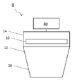
도 10은 본 발명의 실시예들에 따른 장치를 도시한다. 장치(8)는 도 1 내지 9 중 어느 하나를 참조하여 본 명세서에서 설명된 바와 같은, 장치 중 임의의 하나를 포함할 수 있으며, 액추에이터 장치(actuator arrangement)(80)를 포함한다. 액추에이터 장치(80)는 펄스화된 광대역 방사선 소스(10), 광 가이드(12)의 제1 부분(14), 및 광 가이드의(12)의 제2 부분(16) 중 하나 이상을, 제1 부분(14), 제2 부분(16) 및 펄스화된 광대역 방사선 소스(10) 중 다른 것(들)에 대해 이동시키도록 구성된다.Figure 10 shows an apparatus according to embodiments of the present invention. The
일부 실시예들에서, 액추에이터 장치(80)는 복수의 애추에이터들을 포함할 수 있다. 일부 실시예들에서, 액추에이터 장치(80)는 실질적으로 동시에 장치(8)의 2개 이상의 구성 요소들을 가동시킬(actuate) 수 있다. 일부 실시예들에서, 액추에이터 장치(80)는 펄스화된 광대역 방사선 소스(10) 및/또는 장치(8)의 작동 동안 작동할 수 있다.In some embodiments, the
이 문맥에서 실질적으로 동시에는 동일한 시간에서를 의미할 수 있거나, 하나의 전체 작동 기간의 주기 동안 둘 이상의 작동들이 수행되는 것을 의미할 수도 있다. 실질적으로 동시에는 둘 이상의 작동들이 모두 완료될 때까지 둘 이상의 작동들의 작은 부분들(fractions)을 번갈아 수행하는 것을 의미할 수도 있다.In this context may mean substantially simultaneously at the same time, or it may mean that more than one operation is performed during a period of one entire operating period. At substantially the same time, it may mean performing fractions of two or more operations alternately until two or more operations are all completed.
도 11은 본 발명의 실시예들에 따른 시스템의 개략도이다. 시스템(9)은 장치(8) 및 제어기(controller)(90)를 포함한다. 제어기(90)는 액추에이터 장치(80)의 작동을 제어하도록 구성된다. 제어기(90)는 액추에이터 장치(80)가 가동될 때 제어하도록 구성된다. 일부 실시예들에서, 제어기(90)는 액츄에이터 장치(80)의 가동 거리(distance of actuation) 및/또는 가동 속도(speed of actuation)를 제어하도록 구성된다.11 is a schematic diagram of a system according to embodiments of the present invention. The
일부 실시예들에서, 제어기(90)는 시스템(9)에 의해 착수되는 작동의 파라미터들에 따라 미리-프로그램된다(pre-programmed). 예를 들어, 타겟 영역에서 요구된 방사선 프로파일의 형상은 작동의 주기 동안 달라지도록 배열될 수 있다. 다른 실시예들에서, 제어기(90)는, 예를 들어 작동 동안, 수신되는 신호 및/또는 데이터에 응답할 수 있다. 예를 들어, 신호/데이터는 피드백 회로(feedback circuit) 또는 임의의 다른 유사한 장치(도시되지 않음)으로부터 수신될 수 있다. 이러한 피드백 장치(feedback arrangement)는, 예를 들어 타겟 영역에서의 온도 및/또는 타겟 영역의 크기를 측정할 수 있어, 장치(또는 그 요소들) 및/또는 타겟 물체가 서로에 대해 이동되거나 이동 가능할 수 있는 작동 동안, 장치가 온도 및/또는 타겟 영역 크기(또는, 실제로, 임의의 다른 측정 가능한 파라미터)를 유지하도록 제어될 수 있다.In some embodiments, the
일부 실시예들에서, 시스템(9)은 장치(8)가 장착되는 헤드(head)(92)를 포함한다. 일부 실시예들에서, 장치(8)는 헤드(92)에 일체화된다. 다른 실시예들에서, 장치(8)는 헤드(92)에 고정식으로(fixedly) 또는 피벗 가능하게(pivotably) 장착될 수 있다.In some embodiments, the
일부 실시예들에서, 시스템(9)은 타겟 물체(도시되지 않음)에 대한 헤드(92)의 이동을 제어하는 제2 제어기(second controller)(94)를 더 포함한다. 그러면 타겟 영역은 타겟 물체로 지향된다(directed).In some embodiments, the
일부 실시예들에서, 헤드(92) 및 타겟 물체는 서로 평행한 평면에서 이동(예컨대, 왕복 운동(reciprocate))하도록 구성된다. 부가적으로 또는 대안적으로, 일부 실시예들에 따르면, 헤드(92) 및 타겟 물체는 타겟 물체에 더 가깝게 그리고 타겟 물체로부터 더 멀어지게 이동하도록 구성된다.In some embodiments, the
일부 실시예들에서, 제1 및 제2 제어기들(90, 94) 중 적어도 하나는 시스템(9)의 작동 동안 작동 가능하다. 일부 실시예들에서, 제1 제어기(90) 및 제2 제어기(94)는 시스템(9)의 작동 동안 실질적으로 동시에 작동 가능하다. 이러한 구성은 시스템(9)이 타겟 영역에서 방사선 프로파일을 수용하도록(accommodate) 허용하며, 시스템(9)의 작동 동안 유지되거나 변화된다(changed).In some embodiments, at least one of the first and
시스템(9)은 가열 시스템, 열 처리 시스템, 세정 시스템 및 소결 시스템 중 어느 하나일 수 있다. 시스템(9)은 펄스화된 광대역 방사선 소스(10)가 공정을 수행하기에 적합한 임의의 다른 시스템일 수 있다.The
본 발명의 실시예들은 타겟 영역에 방사선을 투과하는 방법을 포함한다. 방사선은 펄스화된 광대역 방사선 소스로부터 방출되며, 광 가이드를 갖는 펄스화된 광대역 방사선 소스로부터 타겟 영역으로 가이드된다. 광 가이드는 도면들을 참조하여 본 명세서에 설명된 광 가이드들 중 하나에 따른다.Embodiments of the invention include a method of transmitting radiation to a target area. The radiation is emitted from the pulsed broadband radiation source and guided from the pulsed broadband radiation source with the light guide to the target area. The light guide follows one of the light guides described herein with reference to the drawings.
일부 실시예들에서, 상기 방법은 상기 제1 부분, 상기 제2 부분 및 상기 펄스화된 광대역 방사선 소스 중 적어도 하나를, 상기 제1 부분, 상기 제2 부분 및 상기 펄스화된 광대역 방사선 소스의 다른 것(들)에 대해 이동시키는 단계를 더 포함한다.In some embodiments, the method further comprises applying at least one of the first portion, the second portion, and the pulsed broadband radiation source to the other portion of the pulsed broadband radiation source, (S) of the object (s).
본 발명의 다른 실시예는 복합 재료로부터의 복합 물품을 제조하기 위한 방법을 제공한다. 방사선은 펄스화된 광대역 방사선 소스로부터 방출되고, 광 가이드를 갖는 펄스화된 광대역 방사선 소스로부터 복합 재료의 표면에서의 타겟 영역으로 가이드된다.Another embodiment of the present invention provides a method for producing a composite article from a composite material. The radiation is emitted from a pulsed broadband radiation source and guided from a pulsed broadband radiation source having a light guide to a target area at the surface of the composite material.
일부 실시예들에서, 상기 방법들은 타겟 영역의 형태, 또는 타겟 영역에서의 방사선의 강도를 변경 또는 유지하기 위해, 광 가이드의 제1 부분, 광 가이드의 제2 부분 및 펄스화된 광대역 방사선 소스 중 적어도 하나를, 장치의 작동 동안 광 가이드의 제1 부분, 광 가이드의 제2 부분 및 펄스화된 광대역 방사선 소스의 다른 것(들)에 대해 이동시키는 단계를 포함한다.In some embodiments, the methods can be used to change or maintain the shape of the target region, or the intensity of radiation in the target region, by changing the first portion of the light guide, the second portion of the light guide, and the second portion of the pulsed broadband radiation source Moving at least one of the first portion of the light guide, the second portion of the light guide, and the other (s) of the pulsed broadband radiation source during operation of the apparatus.
일부 실시예들에서, 상기 방법들은 접촉 표면과 함께, 장치에 의해 물체의 접촉 영역에 압력을 가하는 단계를 포함한다. 일부 실시예들에서, 압력은 접촉 표면을 지지하는 프레임을 통해 가해진다.In some embodiments, the methods include applying pressure to a contact area of an object with the device, along with the contact surface. In some embodiments, pressure is exerted through the frame supporting the contact surface.
일부 실시예들에서, 상기 방법은 복합물을 열 처리하는 방법이다.In some embodiments, the method is a method of heat treating the composite.
상기 실시예들은 본 발명의 예시적인 예시들로서 이해되어야 한다. 본 발명의 다른 실시예들은 구상된다. 예를 들어, 광 가이드는 펄스화된 광대역 방사선 소스가 삽입되는 리세스(recess) 또는 구멍(hole)을 구비한, 광 투과성 재료의 고체 블록(solid block)일 수 있다. 광 가이드의 다양한 다른 형태들은 본 명세서의 개시 내용에 기초하여 당업자에게 명백할 것이다. 예를 들어, 앞서 언급한 바와 같이, 광 가이드는 타겟 영역에 대하여 광대역 방사선 소스의 앞쪽에 또는 뒤쪽에 있는 일 부분만을 포함할 수 있다. 임의의 일 실시예와 관련하여 설명된 임의의 특징은 단독으로, 또는 설명된 다른 특징들과 조합하여 사용될 수 있고, 임의의 다른 실시예들의 하나 이상의 특징들, 또는 임의의 다른 실시예들의 임의의 조합과 조합하여 사용될 수도 있다. 또한, 상기 설명되지 않은 균등물 및 변형들도 첨부된 특허 청구 범위에 정의된 본 발명의 범위를 벗어나지 않으면서 이용될 수 있다.The above embodiments should be understood as illustrative examples of the present invention. Other embodiments of the invention are envisioned. For example, the light guide may be a solid block of light transmissive material having a recess or hole into which a pulsed broadband radiation source is inserted. Various other forms of the light guide will be apparent to those skilled in the art based on the disclosure herein. For example, as noted above, the light guide may include only a portion of the broadband radiation source relative to the target region, either in front of or behind it. Any feature described in connection with any one embodiment may be used alone or in combination with other features described, and may be implemented in one or more features of any other embodiment, or any Combinations may also be used. It is also to be understood that equivalents and modifications not described above may be utilized without departing from the scope of the invention as defined in the appended claims.
Claims (60)
플래쉬램프를 포함하는 펄스화된 광대역 방사선 소스; 및
상기 펄스화된 광대역 방사선 소스에 의해 방출된 광을 타겟 영역으로 가이드하도록 구성된 광 가이드
를 포함하고,
상기 광 가이드는,
상기 타겟 영역에 대해 상기 펄스화된 광대역 방사선 소스의 앞쪽에 있는 적어도 일 부분을 포함하고,
상기 펄스화된 광대역 방사선 소스의 앞쪽에 있는 적어도 일 부분은,
광 투과성 재료
를 포함하는 장치.An apparatus for producing a composite article from a composite material,
A pulsed broadband radiation source comprising a flash lamp; And
A light guide configured to guide light emitted by the pulsed broadband radiation source to a target area;
Lt; / RTI >
The light guide
At least a portion of the front side of the pulsed broadband radiation source relative to the target region,
At least a portion of the front side of the pulsed broadband radiation source,
Light-transmitting material
/ RTI >
상기 광 가이드는,
상기 타겟 영역에 대해 상기 펄스화된 광대역 방사선 소스의 뒤쪽에 있는 일 부분
을 포함하는 장치.The method according to claim 1,
The light guide
A portion of the back side of the pulsed broadband radiation source for the target region
/ RTI >
상기 광 가이드의 적어도 일 부분은, 상기 장치의 작동 동안, 상기 펄스화된 광대역 방사선 소스에 대해 이동 가능하도록 구성되는 장치.3. The method according to claim 1 or 2,
Wherein at least a portion of the light guide is configured to be movable relative to the pulsed broadband radiation source during operation of the apparatus.
상기 광 투과성 재료는,
상기 펄스화된 광대역 방사선 소스에 의해 방출되는 적외선 파장을 투과시키도록 구성되는 장치.4. The method according to any one of claims 1 to 3,
The light-
And transmit the infrared wavelength emitted by the pulsed broadband radiation source.
상기 타겟 영역에 대해 상기 펄스화된 광대역 방사선 소스 앞쪽에 있는 상기 광 가이드의 상기 부분은,
광 투과성 재료의 블록
을 포함하는 장치.5. The method according to any one of claims 1 to 4,
Said portion of said light guide in front of said pulsed broadband radiation source for said target region,
Blocks of light-transmitting material
/ RTI >
상기 블록은,
광 투과성 재료의 둘 이상의 세그먼트들
을 포함하는 장치.6. The method of claim 5,
The block includes:
At least two segments of the light-
/ RTI >
상기 블록은 석영을 포함하는 장치.The method according to claim 5 or 6,
Wherein the block comprises quartz.
상기 블록은 규산 유리(silica glass)를 포함하는 장치.The method according to claim 5 or 6,
Wherein the block comprises silica glass.
상기 블록의 적어도 하나의 표면은,
광 반사성 코팅을 포함하는 장치.9. The method according to any one of claims 5 to 8,
At least one surface of the block,
An apparatus comprising a light reflective coating.
상기 블록의 출력 표면은,
광이 상기 블록을 나가서 상기 타겟 영역에 미리 결정된 방사선 프로파일을 제공하도록 구성되는 장치.10. The method according to any one of claims 5 to 9,
The output surface of the block,
Wherein light is configured to exit the block to provide a predetermined radiation profile to the target region.
상기 블록의 출력 표면은 상기 원하는 방사선 프로파일을 제공하도록 형상화 및/또는 패시트되는 장치.11. The method of claim 10,
Wherein the output surface of the block is shaped and / or faceted to provide the desired radiation profile.
상기 타겟 영역에 대해 상기 펄스화된 광대역 방사선 소스의 앞쪽에 있는 상기 광 가이드의 상기 부분은,
중공 도파관을 포함하는 장치.4. The method according to any one of claims 1 to 3,
Said portion of said light guide in front of said pulsed broadband radiation source for said target region,
A device comprising a hollow waveguide.
상기 도파관은,
복수의 광 반사성 벽들
을 포함하고,
상기 광 반사성 벽들 중 적어도 하나는,
다른 광 반사성 벽(들)에 대해 이동 가능한 장치.13. The method of claim 12,
The waveguide,
A plurality of light reflective walls
/ RTI >
Wherein at least one of the light-
A device movable relative to another light reflective wall (s).
상기 펄스화된 광대역 방사선 소스는,
상기 광 가이드에 대해 병진 이동하거나, 기울이거나 및/또는 회전하도록 구성되는 장치.14. The method of claim 13,
Wherein the pulsed broadband radiation source comprises:
Wherein the light guide is configured to translate, tilt, and / or rotate relative to the light guide.
상기 타겟 영역에 대해, 상기 펄스화된 광대역 방사선 소스의 앞쪽에 있는 상기 광 가이드의 상기 부분은,
형상화된 렌즈를 포함하는 장치.15. The method according to any one of claims 1 to 14,
For the target area, the portion of the light guide in front of the pulsed broadband radiation source,
A device comprising a shaped lens.
물체의 접촉 영역에 상기 장치에 의한 압력을 가하기 위한 접촉 표면
을 더 포함하는 장치.16. The method according to any one of claims 1 to 15,
A contact surface for applying pressure by the device to a contact area of an object
Lt; / RTI >
상기 접촉 영역은 상기 타겟 영역에 또는 부근에 있는 장치.17. The method of claim 16,
Wherein the contact area is at or near the target area.
상기 타겟 영역은 상기 물체에 있는 장치.18. The method of claim 17,
Wherein the target area is on the object.
상기 접촉 표면은,
상기 타겟 영역에 대해 상기 펄스화된 광대역 방사선 소스의 앞쪽에 있는 상기 광 가이드의 상기 부분과 일체화되는 장치.19. The method according to any one of claims 16 to 18,
The contact surface
And is integrated with the portion of the light guide in front of the pulsed broadband radiation source relative to the target region.
상기 접촉 표면은 상기 형상화된 렌즈에 포함되는 장치.19. A method according to any one of claims 16 to 19 when dependent on claim 15,
Wherein the contact surface is included in the shaped lens.
상기 접촉 표면은 상기 형상화된 블록의 상기 출력 표면에 포함되는 장치.20. A method according to any one of claims 16 to 19, when dependent on claim 9 or claim 10,
Wherein the contact surface is included in the output surface of the shaped block.
상기 광 가이드에 대한 위치에서 상기 접촉 표면을 유지하도록 구성된 지지 프레임
을 더 포함하는 장치.21. The method according to any one of claims 16 to 20,
A support frame configured to hold the contact surface in position relative to the light guide
Lt; / RTI >
상기 접촉 표면은 방사선-통과 크레이들(radiation-transparent cradle)에 포함되는 장치.22. The method according to any one of claims 16 to 20 or 22,
Wherein the contact surface is included in a radiation-transparent cradle.
상기 펄스화된 광대역 방사선 소스 및 상기 광 가이드 또는 상기 광 가이드의 일 부분 중 하나 이상을 이동시키는 액추에이터
를 더 포함하는 장치.24. The method according to any one of claims 1 to 23,
An actuator for moving at least one of the pulsed broadband radiation source and a portion of the light guide or the light guide;
Lt; / RTI >
플래쉬램프를 포함하는 펄스화된 광대역 방사선 소스로부터 방사선을 방출시키는 단계; 및
상기 펄스화된 광대역 방사선 소스로부터 방출된 상기 광을 광 가이드로 가이드하는 단계
를 포함하고,
상기 광 가이드는,
상기 복합 재료의 표면에서의 타겟 영역에 대해, 상기 펄스화된 광대역 방사선 소스의 앞쪽에 있는 적어도 일 부분
을 포함하고,
상기 펄스화된 광대역 방사선 소스의 앞쪽에 있는 상기 부분은,
광 투과성 재료
를 포함하는 방법.A method for producing a composite article from a composite material,
Emitting radiation from a pulsed broadband radiation source comprising a flash lamp; And
Guiding the light emitted from the pulsed broadband radiation source to a light guide
Lt; / RTI >
The light guide
For a target area at the surface of the composite material, at least one portion in front of the pulsed broadband radiation source
/ RTI >
The portion of the front side of the pulsed broadband radiation source,
Light-transmitting material
≪ / RTI >
상기 광 가이드는, 상기 타겟 영역에 대해, 상기 펄스화된 광대역 방사선 소스의 뒤쪽에 있는 제1 부분을 포함하는
방법.26. The method of claim 25,
Wherein the light guide comprises, for the target area, a first portion of the pulsed broadband radiation source,
Way.
상기 타겟 영역의 형태 또는 상기 타겟 영역에서 방사선의 강도를 수정하거나 유지하기 위하여, 상기 장치의 작동 동안 상기 광 가이드의 적어도 일 부분 및 상기 펄스화된 광대역 방사선 소스를 서로에 대해 이동시키는 단계
를 포함하는 방법.27. The method of claim 25 or 26,
Moving at least a portion of the light guide and the pulsed broadband radiation source relative to each other during operation of the apparatus to modify or maintain the shape of the target region or the intensity of radiation in the target region
≪ / RTI >
미리 결정된 방사선 프로파일로 상기 광 가이드를 통해 상기 타겟 영역으로 광을 투과시키는 단계
를 포함하는 방법.28. The method according to any one of claims 25 to 27,
Transmitting light through the light guide to the target area with a predetermined radiation profile
≪ / RTI >
상기 광 투과성 재료는,
상기 펄스화된 광대역 방사선 소스에 의해 방출된 적외선 파장을 투과시키도록 구성되는 방법.29. The method according to any one of claims 25 to 28,
The light-
And transmit the infrared wavelength emitted by the pulsed broadband radiation source.
상기 타겟 영역에 대해, 상기 펄스화된 광대역 방사선 소스의 앞쪽에 있는 상기 광 가이드의 상기 부분은,
광 투과성 재료의 블록을 포함하는 방법.30. The method according to any one of claims 25 to 29,
For the target area, the portion of the light guide in front of the pulsed broadband radiation source,
≪ / RTI > wherein the block comprises a block of light-transmitting material.
상기 광 투과성 재료는 둘 이상의 세그먼트들을 포함하는
방법.31. The method of claim 30,
Wherein the light transmissive material comprises at least two segments
Way.
상기 광 가이드는,
상기 광 투과성 재료의 블록의 적어도 하나의 표면에서의 광 반사성 코팅을 포함하는 방법.32. The method according to claim 30 or 31,
The light guide
And a light reflective coating on at least one surface of the block of light transmitting material.
상기 블록의 출력 표면은,
상기 원하는 방사선 프로파일을 제공하도록 형상화 및/또는 패시트되는 방법.29. The method according to any one of claims 30-32 and 28,
The output surface of the block,
Gt; and / or < / RTI > to provide said desired radiation profile.
상기 광 가이드의 적어도 일 부분은,
상기 타겟 영역에 대해, 상기 펄스화된 광대역 방사선 소스의 앞쪽에 있고,
중공 도파관을 포함하는 방법.30. The method according to any one of claims 25 to 29,
At least a portion of the light guide,
For the target region, in front of the pulsed broadband radiation source,
A method comprising the hollow waveguide.
상기 중공 도파관에 포함된 복수의 광 반사성 벽들 중 적어도 하나를, 다른 광 반사성 벽(들)에 대해 이동시키는 단계
를 포함하는 방법.35. The method of claim 34,
Moving at least one of the plurality of light reflective walls included in the hollow waveguide relative to the other light reflective wall (s)
≪ / RTI >
상기 광 가이드와 관련하여 상기 펄스화된 광대역 방사선 소스를 기울이거나 및/또는 회전시키는 단계
를 포함하는 방법.36. The method according to any one of claims 25 to 35,
Tilting and / or rotating the pulsed broadband radiation source with respect to the light guide
≪ / RTI >
액추에이터로 상기 광 가이드 또는 상기 광 가이드의 적어도 일 부분에 관련된 상기 펄스화된 광대역 방사선 소스를 이동시키는 단계
를 포함하는 방법.37. The method according to any one of claims 25 to 36,
Moving the pulsed broadband radiation source associated with at least a portion of the light guide or light guide with an actuator
≪ / RTI >
상기 타겟 영역에 대해, 상기 펄스화된 광대역 방사선 소스의 앞쪽에 있는 상기 광 가이드의 상기 부분은,
형상화된 렌즈를 포함하는 방법.37. The method according to any one of claims 25 to 37,
For the target area, the portion of the light guide in front of the pulsed broadband radiation source,
≪ / RTI >
접촉 표면으로, 물체의 접촉 영역에 상기 장치에 의한 압력을 가하는 단계
를 포함하는 방법.39. The method according to any one of claims 25 to 38,
Applying pressure by the device to the contact area of the object to the contact surface
≪ / RTI >
상기 접촉 영역은 상기 타겟 영역에 또는 부근에 있는 방법.40. The method of claim 39,
Wherein the contact area is at or near the target area.
상기 타겟 영역은 상기 물체에 있는 방법.41. The method of claim 40,
Wherein the target area is in the object.
상기 접촉 표면은,
상기 타겟 영역에 대해, 상기 펄스화된 광대역 방사선 소스의 앞쪽에 있는 상기 광 가이드의 상기 부분과 일체화되는 방법.42. The method according to any one of claims 39 to 41,
The contact surface
And for the target area is integrated with the portion of the light guide in front of the pulsed broadband radiation source.
상기 접촉 표면은,
상기 형상화된 렌즈에 포함되는 방법.39. The method according to any one of claims 42 and 38,
The contact surface
Wherein the shaped lens is included in the shaped lens.
상기 접촉 표면은,
상기 형상화된 블록의 상기 출력 표면에 포함되는 방법.33. The method according to any one of claims 42 and 33,
The contact surface
Wherein the block is included in the output surface of the shaped block.
상기 광 가이드에 대한 위치에서 상기 접촉 표면을 유지하도록 구성되는 지지체 프레임
을 더 포함하는 방법.44. The method according to any one of claims 39 to 43,
A support frame configured to maintain the contact surface in position relative to the light guide;
≪ / RTI >
상기 접촉 표면은,
방사선-통과 크레이들에 포함되는 방법.46. The method according to any one of claims 39 to 43 or 45,
The contact surface
A method of incorporating into a radiation-passing cradle.
제25항 내지 제46항 중 어느 한 항에 따른 방법을 포함하는 방법.In a method for heat treating a composite,
46. A method comprising the method according to any one of claims 25 to 46.
제24항의 상기 장치; 및
상기 액추에이터의 작동을 제어하도록 구성된 제어기
를 포함하는 시스템.In the system,
The apparatus of claim 24; And
A controller configured to control operation of the actuator
/ RTI >
상기 장치가 장착되는 헤드; 및
상기 타겟 물체에 대해 상기 헤드의 이동을 제어하는 제2 제어기
를 포함하고,
상기 타겟 영역은 상기 타겟 물체에 있는
시스템.49. The method of claim 48,
A head on which said apparatus is mounted; And
A second controller for controlling movement of the head relative to the target object,
Lt; / RTI >
Wherein the target area
system.
상기 제1 및 제2 제어기들은,
상기 시스템의 작동 동안 실질적으로 동시에 작동 가능한 시스템.50. The method of claim 49,
The first and second controllers may comprise:
Wherein the system is operable substantially simultaneously during operation of the system.
펄스화된 광대역 방사선 소스; 및
타겟 영역에 상기 펄스화된 광대역 소스에 의해 방출된 광을 가이드하도록 구성된 광 가이드
를 포함하고,
상기 광 가이드, 또는 상기 광 가이드의 적어도 일 부분, 및 상기 펄스화된 광대역 방사선 소스는,
서로에 대해 이동 가능하도록 구성되는
장치.In the apparatus,
A pulsed broadband radiation source; And
A light guide configured to guide light emitted by the pulsed broadband source into a target area
Lt; / RTI >
The light guide, or at least a portion of the light guide, and the pulsed broadband radiation source,
Are configured to be movable relative to each other
Device.
상기 장치는,
펄스화된 광대역 방사선 소스; 및
타겟 영역에 상기 펄스화된 광대역 소스에 의해 방출된 광을 가이드하도록 구성된 광 가이드
를 포함하고,
상기 광 가이드는,
상기 타겟 영역에 대해, 상기 펄스화된 광대역 방사선 소스의 앞쪽에 있는 적어도 일 부분을 포함하는
장치.An apparatus for producing a composite article from a composite material,
The apparatus comprises:
A pulsed broadband radiation source; And
A light guide configured to guide light emitted by the pulsed broadband source into a target area
Lt; / RTI >
The light guide
For the target region, at least a portion of the front side of the pulsed broadband radiation source
Device.
상기 장치는,
펄스화된 광대역 방사선 소스; 및
타겟 영역에 상기 펄스화된 광대역 소스에 의해 방출된 광을 가이드하도록 구성된 광 가이드
를 포함하고,
상기 광 가이드, 또는 상기 광 가이드의 적어도 일 부분, 및 상기 펄스화된 광대역 방사선 소스는,
서로에 대해 이동 가능하도록 구성되는
가열 시스템.A heating system comprising an apparatus,
The apparatus comprises:
A pulsed broadband radiation source; And
A light guide configured to guide light emitted by the pulsed broadband source into a target area
Lt; / RTI >
The light guide, or at least a portion of the light guide, and the pulsed broadband radiation source,
Are configured to be movable relative to each other
Heating system.
상기 장치는,
펄스화된 광대역 방사선 소스; 및
타겟 영역에 상기 펄스화된 광대역 소스에 의해 방출된 광을 가이드하도록 구성된 광 가이드
를 포함하고,
상기 광 가이드는,
상기 타겟 영역에 대해, 상기 펄스화된 광대역 방사선 소스의 앞쪽에 있는 적어도 일 부분을 포함하는
가열 시스템.A heating system comprising an apparatus,
The apparatus comprises:
A pulsed broadband radiation source; And
A light guide configured to guide light emitted by the pulsed broadband source into a target area
Lt; / RTI >
The light guide
For the target region, at least a portion of the front side of the pulsed broadband radiation source
Heating system.
상기 장치는,
펄스화된 광대역 방사선 소스; 및
타겟 영역에 상기 펄스화된 광대역 소스에 의해 방출된 광을 가이드하도록 구성된 광 가이드
를 포함하고,
상기 광 가이드, 또는 상기 광 가이드의 적어도 일 부분, 및 상기 펄스화된 광대역 방사선 소스는,
서로에 대해 이동 가능하도록 구성되는
세정 시스템.A cleaning system comprising an apparatus,
The apparatus comprises:
A pulsed broadband radiation source; And
A light guide configured to guide light emitted by the pulsed broadband source into a target area
Lt; / RTI >
The light guide, or at least a portion of the light guide, and the pulsed broadband radiation source,
Are configured to be movable relative to each other
Cleaning system.
상기 장치는,
펄스화된 광대역 방사선 소스; 및
타겟 영역에 상기 펄스화된 광대역 소스에 의해 방출된 광을 가이드하도록 구성된 광 가이드
를 포함하고,
상기 광 가이드는,
상기 타겟 영역에 대해, 상기 펄스화된 광대역 방사선 소스의 앞쪽에 있는 적어도 일 부분을 포함하는
세정 시스템.A cleaning system comprising an apparatus,
The apparatus comprises:
A pulsed broadband radiation source; And
A light guide configured to guide light emitted by the pulsed broadband source into a target area
Lt; / RTI >
The light guide
For the target region, at least a portion of the front side of the pulsed broadband radiation source
Cleaning system.
상기 장치는,
펄스화된 광대역 방사선 소스; 및
타겟 영역에 상기 펄스화된 광대역 소스에 의해 방출된 광을 가이드하도록 구성된 광 가이드
를 포함하고,
상기 광 가이드, 또는 상기 광 가이드의 적어도 일 부분, 및 상기 펄스화된 광대역 방사선 소스는,
서로에 대해 이동 가능하도록 구성되는
소결 시스템.A sintering system comprising an apparatus,
The apparatus comprises:
A pulsed broadband radiation source; And
A light guide configured to guide light emitted by the pulsed broadband source into a target area
Lt; / RTI >
The light guide, or at least a portion of the light guide, and the pulsed broadband radiation source,
Are configured to be movable relative to each other
Sintering system.
상기 장치는,
펄스화된 광대역 방사선 소스; 및
타겟 영역에 상기 펄스화된 광대역 소스에 의해 방출된 광을 가이드하도록 구성된 광 가이드
를 포함하고,
상기 광 가이드는,
상기 타겟 영역에 대해, 상기 펄스화된 광대역 방사선 소스의 앞쪽에 있는 적어도 일 부분을 포함하는
소결 시스템.A sintering system comprising an apparatus,
The apparatus comprises:
A pulsed broadband radiation source; And
A light guide configured to guide light emitted by the pulsed broadband source into a target area
Lt; / RTI >
The light guide
For the target region, at least a portion of the front side of the pulsed broadband radiation source
Sintering system.
펄스화된 광대역 방사선 소스로부터 방사선을 방출시키는 단계;
상기 펄스화된 광대역 방사선 소스로부터 방출된 상기 광을 광 가이드로 가이드하는 단계; 및
상기 광 가이드 또는 상기 광 가이드의 일 부분에 대해 상기 펄스화된 광대역 방사선 소스를 이동시키는 단계
를 포함하는 방법.A method of transmitting radiation to a target area,
Emitting radiation from a pulsed broadband radiation source;
Guiding the light emitted from the pulsed broadband radiation source to a light guide; And
Moving the pulsed broadband radiation source relative to a portion of the light guide or light guide
≪ / RTI >
펄스화된 광대역 방사선 소스로부터 방사선을 방출시키는 단계; 및
상기 펄스화된 광대역 방사선 소스로부터 방출된 상기 광을 광 가이드로 가이드하는 단계
를 포함하고,
상기 광 가이드는,
상기 복합 재료의 표면에서의 타겟 영역에 대해, 상기 펄스화된 광대역 방사선 소스의 앞쪽에 있는 적어도 일 부분을 포함하는
방법.A method for producing a composite article from a composite material,
Emitting radiation from a pulsed broadband radiation source; And
Guiding the light emitted from the pulsed broadband radiation source to a light guide
Lt; / RTI >
The light guide
For a target region at the surface of the composite material, at least a portion of the pulsed broadband radiation source in front of it
Way.
Applications Claiming Priority (3)
| Application Number | Priority Date | Filing Date | Title |
|---|---|---|---|
| GBGB1601974.7A GB201601974D0 (en) | 2016-02-03 | 2016-02-03 | Pulsed light system |
| GB1601974.7 | 2016-02-03 | ||
| PCT/GB2017/050273 WO2017134453A1 (en) | 2016-02-03 | 2017-02-03 | Pulsed light system |
Publications (1)
| Publication Number | Publication Date |
|---|---|
| KR20180107222A true KR20180107222A (en) | 2018-10-01 |
Family
ID=55590644
Family Applications (1)
| Application Number | Title | Priority Date | Filing Date |
|---|---|---|---|
| KR1020187025275A KR20180107222A (en) | 2016-02-03 | 2017-02-03 | Pulsed optical system |
Country Status (9)
| Country | Link |
|---|---|
| US (2) | US11559922B2 (en) |
| EP (1) | EP3411210B1 (en) |
| JP (1) | JP7039474B2 (en) |
| KR (1) | KR20180107222A (en) |
| CN (2) | CN112008922B (en) |
| BR (1) | BR112018015746B1 (en) |
| CA (1) | CA3013451A1 (en) |
| GB (1) | GB201601974D0 (en) |
| WO (1) | WO2017134453A1 (en) |
Families Citing this family (10)
| Publication number | Priority date | Publication date | Assignee | Title |
|---|---|---|---|---|
| FR3080563B1 (en) | 2018-04-25 | 2021-10-15 | Coriolis Group | FIBER APPLICATION HEAD INCLUDING SEVERAL COMPACTION ROLLERS |
| FR3080562B1 (en) | 2018-04-25 | 2020-04-24 | Coriolis Group | FIBER APPLICATION HEAD COMPRISING COMPACTION JACKS ASSOCIATED WITH FUNCTIONAL MODULES |
| FR3080564B1 (en) | 2018-04-25 | 2020-04-24 | Coriolis Group | FIBER APPLICATION HEAD COMPRISING HEATING MEANS ASSOCIATED WITH FUNCTIONAL MODULES |
| FR3080565B1 (en) | 2018-04-25 | 2020-04-24 | Coriolis Group | FIBER APPLICATION HEAD COMPRISING MULTIPLE MOBILE FUNCTIONAL MODULES IN TRANSLATION FOR CARRYING OUT MAINTENANCE OPERATIONS |
| EP3703472A1 (en) | 2019-03-01 | 2020-09-02 | Heraeus Noblelight Ltd. | Arc discharge lamp system and apparatus comprising an arc discharge lamp system |
| FR3093947B1 (en) * | 2019-03-21 | 2021-04-09 | Centre Techn Ind Mecanique | Method and installation for manufacturing a composite material revolution part |
| FR3100153B1 (en) | 2019-09-02 | 2022-10-14 | Coriolis Group | FIBER APPLICATION HEAD WITH PARTICULAR SOFT ROLLER |
| FR3100154B1 (en) | 2019-09-04 | 2021-07-23 | Coriolis Group | FIBER APPLICATION HEAD WITH RIGID RING ROLLER |
| FR3105072B1 (en) | 2019-12-19 | 2021-12-31 | Coriolis Group | FIBER APPLICATION HEAD WITH RETRACTABLE SHUTTER |
| FR3107001B1 (en) | 2020-02-06 | 2023-06-02 | Coriolis Group | FIBER APPLICATION HEADS WITH ON-BOARD REELS |
Family Cites Families (33)
| Publication number | Priority date | Publication date | Assignee | Title |
|---|---|---|---|---|
| DE2552966A1 (en) | 1975-11-26 | 1977-06-02 | Dokoupil Jiri | Mechanism for testing continuity of leather - uses array of light guide fibres in roller mechanism, light source and photocell |
| JPS61196008U (en) * | 1985-05-30 | 1986-12-06 | ||
| JPS6468250A (en) * | 1987-09-08 | 1989-03-14 | Kanebo Ltd | Method and apparatus for curing dental visible light polymerizable resin |
| JP2554271B2 (en) | 1988-08-12 | 1996-11-13 | 日本化薬株式会社 | Process for producing alkali metal salt of (-)-N- (1-alkoxycarbonylpropen-2-yl) -a-amino-a- (p-hydroxyphenyl) acetic acid |
| JPH047810U (en) * | 1990-05-11 | 1992-01-24 | ||
| DE4034834C2 (en) | 1990-11-02 | 1995-03-23 | Heraeus Noblelight Gmbh | Process for the production of metallic layers on substrates and use of the layers |
| GB9614659D0 (en) * | 1996-07-12 | 1996-09-04 | Askin Michael | Method and apparatus to provide a welded plastic sealing strip |
| DE19636266A1 (en) * | 1996-09-06 | 1998-03-12 | Kaltenbach & Voigt | Method and device for curing photosensitive polymeric compositions |
| US5832362A (en) * | 1997-02-13 | 1998-11-03 | The Procter & Gamble Company | Apparatus for generating parallel radiation for curing photosensitive resin |
| US6208783B1 (en) * | 1997-03-13 | 2001-03-27 | Cirrex Corp. | Optical filtering device |
| US5975895A (en) | 1997-11-12 | 1999-11-02 | Coltene/Whaledent | Strobe light curing apparatus and method |
| US6451152B1 (en) * | 2000-05-24 | 2002-09-17 | The Boeing Company | Method for heating and controlling temperature of composite material during automated placement |
| US6751516B1 (en) * | 2000-08-10 | 2004-06-15 | Richardson Technologies, Inc. | Method and system for direct writing, editing and transmitting a three dimensional part and imaging systems therefor |
| US7270528B2 (en) * | 2002-05-07 | 2007-09-18 | 3D Systems, Inc. | Flash curing in selective deposition modeling |
| US6713713B1 (en) * | 2002-12-18 | 2004-03-30 | Branson Ultrasonics Corporation | Lens to adapt laser intensity for uniform welding |
| DE10261642A1 (en) * | 2002-12-27 | 2004-07-15 | Laserquipment Ag | Method and device for welding thermoplastic molded parts, in particular for contour welding three-dimensional molded parts |
| JP2004284244A (en) * | 2003-03-24 | 2004-10-14 | Sekisui Chem Co Ltd | Manufacturing method for fiber-reinforced plastic pipe |
| EP1697682A2 (en) | 2003-12-02 | 2006-09-06 | 3M Innovative Properties Company | Irradiation systems |
| JP2005334024A (en) * | 2004-05-24 | 2005-12-08 | Gc Corp | Dental restoration aid |
| US20070047932A1 (en) * | 2005-08-31 | 2007-03-01 | Branson Ultrasonics Corporation | Waveguide for plastics welding using an incoherent infrared light source |
| US20070189018A1 (en) | 2006-02-16 | 2007-08-16 | Delaware Capital Formation, Inc. | Curing system and method of curing |
| FR2909276A1 (en) * | 2006-12-04 | 2008-06-06 | Satelec Sa | Photopolymerization device for e.g. filling material, in dental field, has unit measuring intensity of light reflected by material, and control circuit to automatically control power and lighting duration of source based on measurement |
| ES2397294T3 (en) * | 2008-03-11 | 2013-03-06 | Shaser, Inc. | Improvement of optical radiation system used in dermatological treatments |
| JP2010015772A (en) | 2008-07-02 | 2010-01-21 | Olympus Corp | Light source device |
| FR2957841B1 (en) * | 2010-03-24 | 2012-07-06 | Plasticell | APPARATUS FOR WELDING THERMOPLASTIC MEMBRANES |
| US8907258B2 (en) * | 2010-04-08 | 2014-12-09 | Ncc Nano, Llc | Apparatus for providing transient thermal profile processing on a moving substrate |
| JP5982744B2 (en) * | 2011-07-08 | 2016-08-31 | 東洋製罐株式会社 | Heating device, heating method, molding device, and plastic molding product molding method |
| KR101656094B1 (en) * | 2012-03-22 | 2016-09-08 | 도요세이칸 그룹 홀딩스 가부시키가이샤 | Method of molding a thermoplastic resin article and apparatus for molding same |
| GB201214917D0 (en) * | 2012-08-22 | 2012-10-03 | Univ Bristol | Composite articles |
| WO2014135176A1 (en) | 2013-03-07 | 2014-09-12 | Giuseppe Caccia | Pulsed light control system for skin treatments |
| KR102147938B1 (en) * | 2013-12-27 | 2020-08-25 | 엘지이노텍 주식회사 | Lighting device |
| TR201904008T4 (en) * | 2014-03-28 | 2019-04-22 | Automotive Lighting Italia S P A A Socio Unico | Laser welding method of an automobile lamp. |
| JP6468250B2 (en) | 2016-06-21 | 2019-02-13 | 京セラドキュメントソリューションズ株式会社 | Image forming apparatus |
-
2016
- 2016-02-03 GB GBGB1601974.7A patent/GB201601974D0/en not_active Ceased
-
2017
- 2017-02-03 CA CA3013451A patent/CA3013451A1/en active Pending
- 2017-02-03 CN CN202010919677.0A patent/CN112008922B/en active Active
- 2017-02-03 BR BR112018015746-5A patent/BR112018015746B1/en active IP Right Grant
- 2017-02-03 JP JP2018541220A patent/JP7039474B2/en active Active
- 2017-02-03 CN CN201780009477.8A patent/CN108602212B/en active Active
- 2017-02-03 KR KR1020187025275A patent/KR20180107222A/en unknown
- 2017-02-03 WO PCT/GB2017/050273 patent/WO2017134453A1/en active Application Filing
- 2017-02-03 EP EP17708301.1A patent/EP3411210B1/en active Active
-
2018
- 2018-08-03 US US16/054,143 patent/US11559922B2/en active Active
-
2022
- 2022-10-05 US US17/960,536 patent/US20240116220A1/en active Pending
Also Published As
| Publication number | Publication date |
|---|---|
| EP3411210B1 (en) | 2022-05-11 |
| CN112008922A (en) | 2020-12-01 |
| US20240116220A1 (en) | 2024-04-11 |
| CN108602212A (en) | 2018-09-28 |
| JP2019507693A (en) | 2019-03-22 |
| BR112018015746B1 (en) | 2022-08-23 |
| JP7039474B2 (en) | 2022-03-22 |
| US11559922B2 (en) | 2023-01-24 |
| CN108602212B (en) | 2020-10-02 |
| US20180339434A1 (en) | 2018-11-29 |
| CN112008922B (en) | 2022-07-12 |
| WO2017134453A1 (en) | 2017-08-10 |
| BR112018015746A2 (en) | 2019-01-08 |
| EP3411210A1 (en) | 2018-12-12 |
| CA3013451A1 (en) | 2017-08-10 |
| GB201601974D0 (en) | 2016-03-16 |
Similar Documents
| Publication | Publication Date | Title |
|---|---|---|
| US20240116220A1 (en) | Pulsed light system | |
| ES2660497T3 (en) | Method and apparatus for manufacturing composite items | |
| JP6256813B2 (en) | Phototherapy device | |
| US20140305919A1 (en) | Unit for heat treating container preforms with double walls radiating in a staggered configuration | |
| KR102581430B1 (en) | hair styling device | |
| US11812834B2 (en) | Ultraviolet curing apparatus for nail art | |
| JP6014834B1 (en) | Laser welding method for light transmitting resin and laser welding apparatus for light transmitting resin | |
| JP3531567B2 (en) | Flash irradiation heating device | |
| EP2964446B1 (en) | Heating system for pet-preforms | |
| JP5710592B2 (en) | Heating system and method for heating a preform body | |
| US20100019417A1 (en) | Device and method for curing hearing aid housings | |
| EP0329604A1 (en) | Process and device for hardening similar elements fixed to a common support in a regularly spaced manner | |
| US20090039058A1 (en) | Equipment and method for fusing together laminar bands | |
| KR101953442B1 (en) | Apparatus for intense pulsed light sintering with water colorable | |
| CN107056090B (en) | Fiber coating device, fiber coating method and fiber | |
| KR102383317B1 (en) | Apparatus for intense pulsed light sintering | |
| ITTO20130252A1 (en) | MACHINE FOR CUTTING A LAMINATED GLASS SHEET | |
| NL2026720B1 (en) | Reflector for curing optical fibers and methods of using the same | |
| KR102196036B1 (en) | An ultraviolet light curing device capable of varying the ultraviolet output according to the state of the three-dimensional laminate | |
| KR20170129429A (en) | Sintering apparatus using a lighting | |
| FI124403B (en) | A method for performing infrared processing | |
| IT202000003970A1 (en) | Equipment for laser welding of plastic materials and related procedure | |
| IT201800005899A1 (en) | Equipment for laser welding of plastic materials and related procedure. | |
| TW201417977A (en) | A method for heating a mold by laser and a mold apparatus using the same |