KR20180103059A - Consistent editing of light field data - Google Patents
Consistent editing of light field data Download PDFInfo
- Publication number
- KR20180103059A KR20180103059A KR1020187019625A KR20187019625A KR20180103059A KR 20180103059 A KR20180103059 A KR 20180103059A KR 1020187019625 A KR1020187019625 A KR 1020187019625A KR 20187019625 A KR20187019625 A KR 20187019625A KR 20180103059 A KR20180103059 A KR 20180103059A
- Authority
- KR
- South Korea
- Prior art keywords
- view
- scene
- views
- location
- image
- Prior art date
Links
- 238000000034 method Methods 0.000 claims abstract description 70
- 230000003287 optical effect Effects 0.000 claims abstract description 43
- 230000009466 transformation Effects 0.000 claims description 32
- PXFBZOLANLWPMH-UHFFFAOYSA-N 16-Epiaffinine Natural products C1C(C2=CC=CC=C2N2)=C2C(=O)CC2C(=CC)CN(C)C1C2CO PXFBZOLANLWPMH-UHFFFAOYSA-N 0.000 claims description 19
- 238000004891 communication Methods 0.000 claims description 10
- 238000000844 transformation Methods 0.000 claims description 5
- 238000004422 calculation algorithm Methods 0.000 claims description 3
- 238000004590 computer program Methods 0.000 claims description 3
- 239000013598 vector Substances 0.000 claims description 3
- 238000009877 rendering Methods 0.000 claims description 2
- 125000003983 fluorenyl group Chemical group C1(=CC=CC=2C3=CC=CC=C3CC12)* 0.000 claims 1
- 230000006870 function Effects 0.000 description 12
- 239000011159 matrix material Substances 0.000 description 9
- 238000003860 storage Methods 0.000 description 9
- 238000012545 processing Methods 0.000 description 7
- 238000010586 diagram Methods 0.000 description 5
- 238000005457 optimization Methods 0.000 description 5
- 230000008569 process Effects 0.000 description 5
- 238000013459 approach Methods 0.000 description 4
- 238000009826 distribution Methods 0.000 description 3
- 238000004364 calculation method Methods 0.000 description 2
- 230000009977 dual effect Effects 0.000 description 2
- 238000003384 imaging method Methods 0.000 description 2
- 230000001902 propagating effect Effects 0.000 description 2
- 210000001747 pupil Anatomy 0.000 description 2
- 230000000007 visual effect Effects 0.000 description 2
- 238000013473 artificial intelligence Methods 0.000 description 1
- 230000008859 change Effects 0.000 description 1
- 239000000470 constituent Substances 0.000 description 1
- 238000013481 data capture Methods 0.000 description 1
- 238000000354 decomposition reaction Methods 0.000 description 1
- 238000001514 detection method Methods 0.000 description 1
- 238000005516 engineering process Methods 0.000 description 1
- 238000004519 manufacturing process Methods 0.000 description 1
- 238000012986 modification Methods 0.000 description 1
- 230000004048 modification Effects 0.000 description 1
- 230000003387 muscular Effects 0.000 description 1
- 238000004321 preservation Methods 0.000 description 1
- 239000004065 semiconductor Substances 0.000 description 1
- 230000007704 transition Effects 0.000 description 1
Images


Classifications
-
- G—PHYSICS
- G06—COMPUTING; CALCULATING OR COUNTING
- G06T—IMAGE DATA PROCESSING OR GENERATION, IN GENERAL
- G06T3/00—Geometric image transformations in the plane of the image
- G06T3/18—Image warping, e.g. rearranging pixels individually
-
- G—PHYSICS
- G06—COMPUTING; CALCULATING OR COUNTING
- G06T—IMAGE DATA PROCESSING OR GENERATION, IN GENERAL
- G06T3/00—Geometric image transformations in the plane of the image
- G06T3/06—Topological mapping of higher dimensional structures onto lower dimensional surfaces
-
- G06T3/0031—
-
- G—PHYSICS
- G06—COMPUTING; CALCULATING OR COUNTING
- G06T—IMAGE DATA PROCESSING OR GENERATION, IN GENERAL
- G06T15/00—3D [Three Dimensional] image rendering
- G06T15/10—Geometric effects
- G06T15/20—Perspective computation
- G06T15/205—Image-based rendering
-
- G06T3/0093—
-
- G—PHYSICS
- G06—COMPUTING; CALCULATING OR COUNTING
- G06T—IMAGE DATA PROCESSING OR GENERATION, IN GENERAL
- G06T2207/00—Indexing scheme for image analysis or image enhancement
- G06T2207/10—Image acquisition modality
- G06T2207/10052—Images from lightfield camera
Landscapes
- Engineering & Computer Science (AREA)
- Theoretical Computer Science (AREA)
- Physics & Mathematics (AREA)
- General Physics & Mathematics (AREA)
- Computing Systems (AREA)
- Geometry (AREA)
- Computer Graphics (AREA)
- Image Processing (AREA)
- Stereoscopic And Panoramic Photography (AREA)
Abstract
본 발명은 상이한 뷰포인트들로부터 취해진 장면의 몇몇 뷰들로 구성된, 3D 장면의 광 필드 캡처에 기하학적 워프를 적용하는 방법을 기술한다. 워프는 뷰들의 서브세트에 관한 (소스 포인트, 타겟 포인트) 위치 제약들의 세트로서 명시된다. 이러한 위치 제약들은 모든 뷰들로 전파되고, 워핑된 이미지가 각각의 뷰에 대하여 생성되며, 이러한 방식으로 이들 워핑된 이미지들은 뷰들에 걸쳐 3D 에서 기하학적으로 일치한다.The present invention describes a method of applying a geometric warp to an optical field capture of a 3D scene, consisting of several views of a scene taken from different viewpoints. A warp is specified as a set of location constraints (source point, target point) for a subset of views. These position constraints propagate to all views, and warped images are generated for each view, and in this way these warped images geometrically match in 3D across views.
Description
본 개시의 분야는 광 필드 이미징에 관한 것이다. 특히, 본 개시는 광 필드 데이터의 이미지들을 편집하는 기술들에 관한 것이다.Field of the present disclosure relates to optical field imaging. In particular, this disclosure relates to techniques for editing images of optical field data.
본 섹션은 본 기술의 다양한 양태들을 독자에게 소개하기 위한 것이고, 이는 하기에서 설명되고 및/또는 청구되는 본 개시의 다양한 양태들에 관련될 수도 있다. 이 논의는, 본 개시의 다양한 양태들의 더 우수한 이해를 촉진하기 위한 배경 정보를 독자에게 제공함에 있어서 도움이 될 것으로 사료된다. 이에 따라, 이들 진술들은 종래 기술의 시인으로서가 아니라 이러한 관점에서 판독되어야 함이 이해되어야 한다.This section is intended to introduce the reader to various aspects of the technology, which may be related to various aspects of the present disclosure described and / or claimed below. This discussion will be helpful in providing the reader with background information to facilitate a better understanding of the various aspects of the present disclosure. Accordingly, it should be understood that these statements should be read in this regard, and not as a prior art disclosure.
종래의 이미지 캡처 디바이스들은 3 차원 (3D) 장면을 2 차원 센서 상에 렌더링한다. 작동 중에, 종래의 캡처 디바이스는 디바이스 내의 센서 (또는 광 검출기) 의 각 포인트에 도달하는 광의 양을 나타내는 2 차원 (2D) 이미지를 캡처한다. 그러나, 이 2D 이미지는 (광 필드로 지칭될 수도 있는) 센서에 도달하는 광선들의 방향 분포에 관한 어떤 정보도 포함하지 않는다. 예를 들어, 심도는 포착 동안 손실된다. 따라서, 종래의 캡처 디바이스는 장면으로부터의 광 분포에 관한 정보의 대부분을 저장하지 않는다.Conventional image capture devices render a three-dimensional (3D) scene on a two-dimensional sensor. During operation, a conventional capture device captures a two-dimensional (2D) image representing the amount of light reaching each point of a sensor (or photodetector) in the device. However, this 2D image does not contain any information about the directional distribution of the rays reaching the sensor (which may be referred to as the light field). For example, depths are lost during acquisition. Thus, conventional capture devices do not store much of the information about the light distribution from the scene.
("광 필드 데이터 포착 디바이스들" 로도 지칭되는) 광 필드 캡처 디바이스들은 장면의 4 차원 (4D) 광 필드를, 그 장면의 상이한 뷰포인트들에서 광을 캡처함으로써, 측정하도록 설계되었다. 따라서, 센서를 교차하는 광의 각각의 빔을 따라 이동하는 광의 양을 측정함으로써, 이들 디바이스들은 사후 프로세싱에 의해 새로운 이미징 애플리케이션들을 제공하기 위해, 부가적인 광학 정보 (광선들의 번들의 방향성 분포에 관한 정보) 를 캡처할 수 있다. 광 필드 캡처 디바이스에 의해 포착/획득된 정보는 광 필드 데이터로 지칭된다. 광 필드 캡처 디바이스들은 본원에서, 광 필드 데이터를 캡처할 수 있는 임의의 디바이스들로 정의된다.Optical field capture devices (also referred to as " optical field data capture devices ") are designed to measure four-dimensional (4D) light fields of a scene by capturing light at different view points of the scene. Thus, by measuring the amount of light traveling along each beam of light intersecting the sensor, these devices can provide additional optical information (information about the directional distribution of the bundles of rays) to provide new imaging applications by post- Can be captured. The information captured / obtained by the optical field capture device is referred to as optical field data. Optical field capture devices are herein defined as any device capable of capturing optical field data.
광 필드 캡처 디바이스들의 몇몇 그룹들이 존재한다.There are several groups of light field capture devices.
"카메라 어레이" 로도 지칭되는, 광 필드 캡처 디바이스들의 제 1 그룹은 단일 공유 이미지 센서 또는 상이한 이미지 센서들 상에 이미지들을 투영하는 카메라들의 어레이를 구현한다. 그러므로, 이들 디바이스들은 카메라들의 매우 정확한 배열 및 배향을 요구하며, 이는 그들의 제조를 종종 복잡하고 비용이 많이 들게 한다.A first group of optical field capture devices, also referred to as a " camera array ", embodies a single shared image sensor or an array of cameras that project images onto different image sensors. Therefore, these devices require very precise alignment and orientation of the cameras, which makes their manufacture often complex and costly.
"플렌옵틱 디바이스" 또는 "플렌옵틱 카메라" 로도 지칭되는, 광 필드 캡처 디바이스들의 제 2 그룹은 메인 렌즈의 이미지 초점 필드에, 그리고 마이크로 렌즈 당 하나의 마이크로 이미지가 투영되는 포토-센서 전에 위치된 마이크로 렌즈 어레이를 구현한다. 플렌옵틱 카메라들은 마이크로 렌즈 어레이와 그 센서 사이의 거리 (d) 에 따라 2 개의 타입들로 분할된다. "타입 1 플렌옵틱 카메라" 와 관련하여, 이 거리 (d) 는 마이크로 렌즈 초점 길이 (f) 와 동일하다 (R. Ng 등, CSTR, 2(11), 2005 에 의한 문헌 "Light-field photography with a hand-held plenoptic camera" 에 제시됨). "타입 2 플렌옵틱 카메라" 와 관련하여, 이 거리 (d) 는 마이크로 렌즈 초점 길이 (f) 와 상이하다 (A. Lumsdaine 및 T. Georgiev, ICCP, 2009 에 의한 문헌 "The focused plenoptic camera" 에 제시됨). 양자의 타입 1 과 타입 2 의 플렌옵틱 카메라들에 대하여, 각 마이크로 렌즈 아래의 포토 센서의 영역은 마이크로 이미지로 지칭된다. 타입 1 플렌옵틱 카메라들에 대하여, 각각의 마이크로 이미지는 캡처된 장면의 특정 영역을 묘사하며, 마이크로 이미지의 각 픽셀은 메인 렌즈 사출 동공 상의 특정 서브-애퍼처 로케이션의 관점에서 이 특정 영역을 묘사한다. 타입 2 플렌옵틱 카메라들에 대하여, 인접한 마이크로 이미지들은 부분적으로 오버랩할 수도 있다. 따라서, 그러한 오버레이 부분들 내에 로케이트된 하나의 픽셀은 메인 렌즈 사출 동공 상의 상이한 서브-애퍼처 로케이션들에서 굴절된 광선들을 캡처할 수도 있다.A second group of optical field capture devices, also referred to as " planar optical devices " or " planar optical cameras ", are used in the image focus field of the main lens and in micro- Thereby realizing a lens array. Plane-optic cameras are divided into two types according to the distance (d) between the microlens array and its sensor. In relation to the "type flange
광 필드 데이터 프로세싱은 특히, 장면의 리포커싱된 이미지들을 생성하는 것, 장면의 투시도들을 생성하는 것, 장면의 심도 맵들을 생성하는 것, 확장된 피사계 심도 (EDOF) 이미지들을 생성하는 것, 입체 이미지들을 생성하는 것, 및/또는 이들의 임의의 조합을 포함하지만, 이에 제한되지 않는다.Optical field data processing is particularly useful for generating refocused images of scenes, generating perspective views of scenes, generating depth map of scenes, generating extended depth of field (EDOF) images, , ≪ / RTI > and / or any combination thereof.
광 필드 캡처에 대한 관심이 증가하고 있음에도 불구하고, 뷰포인트들에 걸쳐 일관되게 광 필드 데이터를 편집하기 위해 사용가능한 편집 기술들은 많지 않다. (S. Seitz 및 K. M. Kutulakos, in International Conference on Computer Vision, 1998. 에 의한 문헌 "Plenoptic Image Editing" 에 의해 예시된 것과 같은) 대부분의 제안된 방법들은 텍스처 정보를 편집하는 것을 다루지만, 이미지들의 지오메트리를 변경할 수 있는 것은 많지 않다. 그러한 이미지의 기하학적 워핑은 특정 이미지 영역들을 확대하거나 또는 압축하는데 사용될 수 있다. 예를 들어, 이미지에서 캡처된 건물의 창을 더 크게 만들 수 있거나, 또는 그 이미지에서 사람의 가슴을 더 크게 만들어 더 근육질의 외모를 제공할 수 있다.Despite the growing interest in optical field capture, there are not many editing techniques available for consistently editing optical field data across viewpoints. Most of the proposed methods, such as those exemplified by the document " Plenoptic Image Editing " by S. Seitz and KM Kutulakos, in International Conference on Computer Vision, 1998., deal with editing texture information, There is not much that can be changed. The geometric warping of such images can be used to magnify or compress certain image areas. For example, a window of a building captured from an image can be made larger, or a person's chest can be made larger in the image to provide a more muscular appearance.
구체적으로, 종래의 2D 이미지들을 편집하기 위한 편리하고 효율적인 방법은, 소스 포인트 로케이션과 타겟 포인트 로케이션의 쌍들의 세트로 이루어진 희소한 위치 제약들에 의존한다. 각 쌍은 원본 이미지에서 소스 포인트의 로케이션에 있는 픽셀이 결과 이미지에서 대응하는 타겟 포인트의 로케이션으로 이동해야만 한다는 제약들을 시행한다. 이미지 지오메트리의 변화는 소스 이미지에 고밀도 이미지 워핑 변환을 적용함으로써 획득된다. 각 이미지 포인트에서의 변환은 희소한 제어 포인트들에 대한 제약들을 만족시키면서, 로컬 이미지 텍스처 피처들의 보존을 최적화하는 계산 프로세스의 결과로서 획득된다.In particular, a convenient and efficient method for editing conventional 2D images relies on rare position constraints consisting of pairs of source point location and target point location. Each pair imposes constraints that pixels in the source image's location in the source image must move from the resulting image to the corresponding target point's location. The change in image geometry is obtained by applying a high density image warping transformation to the source image. The transformation at each image point is obtained as a result of a computation process that optimizes the preservation of local image texture features while satisfying constraints on the rare control points.
이러한 이미지 워핑 방법은 광 필드에서의 개별 뷰들에 직접 적용될 수 없으며, 이는 뷰들에 오정렬이 발생하여 부조화의 시각적인 문제들을 생성할 것이기 때문이다.This method of image warping can not be applied directly to individual views in the light field because misalignment of views will create visual problems of discrepancy.
따라서, 배경 기술에 대한 개선점들을 나타내는 장치 및 방법을 제공하는 것이 바람직할 것이다.Accordingly, it would be desirable to provide an apparatus and method that demonstrates improvements to the background art.
"일 실시형태", "실시형태", "예시적인 실시형태" 에 대한 명세서에서의 참조들은, 설명된 실시형태가 특정한 피처, 구조, 또는 특징을 포함할 수도 있지만, 모든 실시형태가 반드시 그 특정한 피처, 구조, 또는 특징을 포함하지 않을 수도 있는 것을 나타낸다. 또한, 이러한 문구들은 반드시 동일한 실시형태를 지칭하는 것은 아니다. 또한, 특정한 피처, 구조 또는 특징이 실시형태와 관련하여 설명될 때, 명시적으로 설명되는지 여부에 따라, 다른 실시형태들과 관련하여 그러한 피처, 구조 또는 특징에 영향을 미치도록 당업자의 지식 내에 있다는 것이 제시된다.References in the specification to " one embodiment, " " an embodiment, " and " exemplary embodiment " should be construed to encompass all such modifications, Features, structures, or features. Furthermore, these phrases do not necessarily refer to the same embodiment. It is also to be understood that within the knowledge of those skilled in the art, to the extent that they affect such features, structures, or features in relation to other embodiments, whether or not a particular feature, structure, or characteristic is described explicitly when described in connection with the embodiment .
본 발명의 특정 실시형태는 광 필드 데이터를 일관되게 편집하는 방법에 관한 것으로서,A particular embodiment of the invention relates to a method for consistently editing optical field data,
상기 방법은,The method comprises:
● 적어도 2 개의 참조 뷰들 및 적어도 하나의 추가 뷰를 포함하는 2D 뷰들의 세트로부터 묘사된 3D 장면의 복수의 캘리브레이션된 2D 이미지들을 포함하는 광 필드 데이터,- light field data comprising a plurality of calibrated 2D images of a 3D scene depicted from a set of 2D views comprising at least two reference views and at least one additional view,
● 상기 적어도 2 개의 참조 뷰들과 연관된 위치 제약 파라미터들의 적어도 하나의 초기 세트로서, 상기 위치 제약 파라미터들의 각각은 원래의 2D 이미지를 워핑하기 위해, 상기 적어도 2 개의 참조 뷰들 중에서, 대응하는 뷰로부터 묘사된 3D 장면의 상기 원래의 2D 이미지에서의 주어진 포인트에 적용될 변환을 표현하고, 상기 위치 제약 파라미터들은,- at least one initial set of position constraint parameters associated with the at least two reference views, each of the position constraint parameters comprising at least one of the at least two reference views, A transformation to be applied to a given point in the original 2D image of a 3D scene,
○ 상기 대응하는 뷰로부터 묘사된 상기 3D 장면의 상기 원래의 2D 이미지에서의 주어진 포인트의, 상기 대응하는 뷰에서의 2D 소스 로케이션, A 2D source location in the corresponding view of a given point in the original 2D image of the 3D scene depicted from the corresponding view,
○ 상기 대응하는 뷰로부터 묘사된 상기 3D 장면의 워핑된 2D 이미지에서의 주어진 포인트의, 상기 대응하는 뷰에서의 2D 타겟 로케이션 A 2D target location in the corresponding view of a given point in a warped 2D image of the 3D scene depicted from the corresponding view
을 포함하는, 상기 위치 제약 파라미터들의 적어도 하나의 초기 세트At least one initial set of position constraint parameters,
를 프로세싱하고,Lt; / RTI >
상기 방법은,The method comprises:
● 상기 적어도 2 개의 참조 뷰들과 연관된 상기 위치 제약 파라미터들의 각각에 대해, 상기 3D 장면에서, 상기 2D 소스 로케이션이 상기 대응하는 뷰로의 투영인 3D 소스 로케이션 및 상기 3D 장면에서, 상기 2D 타겟 로케이션이 상기 대응하는 뷰로의 투영인 3D 타겟 로케이션을 결정하는 단계,- for each of said position constraint parameters associated with said at least two reference views, in said 3D scene, in said 3D source location and said 3D scene, said 2D source location is a projection to said corresponding view, Determining a 3D target location that is a projection to a corresponding view,
● 상기 3D 소스 로케이션과 상기 3D 타겟 로케이션의 함수로서, 상기 적어도 하나의 추가 뷰들과 연관된 추가의 위치 제약 파라미터들의 추가의 세트를 결정하는 단계로서, 상기 추가의 위치 제약 파라미터들의 각각은 상기 원래의 2D 이미지를 워핑하기 위해, 상기 적어도 하나의 추가 뷰 중에서, 대응하는 뷰로부터 묘사된 3D 장면의 원래의 2D 이미지에서 주어진 포인트에 적용될 변환을 표현하는, 상기 추가의 위치 제약 파라미터들의 추가의 세트를 결정하는 단계,Determining a further set of additional position constraint parameters associated with the at least one additional views as a function of the 3D source location and the 3D target location, Determining a further set of said additional position constraint parameters representing a transformation to be applied to a given point in the original 2D image of the 3D scene depicted from the corresponding view from among said at least one additional view step,
● 편집된 광 필드 데이터를 획득하기 위해, 상기 2D 뷰들과 연관된 상기 위치 제약 파라미터들의 함수로서, 상기 2D 뷰들의 세트로부터 묘사된 상기 3D 장면의 상기 2D 이미지들의 각각을 워핑하는 단계를 포함한다.And warping each of the 2D images of the 3D scene depicted from the set of 2D views as a function of the position constraint parameters associated with the 2D views to obtain edited light field data.
본 설명에서, "캘리브레이션된 2D 뷰들" 라는 용어들은 3D 장면의 대응하는 투영 행렬이 알려진 2 차원 뷰들을 지칭한다. 이러한 투영 행렬은 3D 공간에서의 임의의 포인트의 2D 뷰로의 투영을 결정하는 것을 허용한다. 반대로, 2D 뷰의 이미지 상에 임의의 포인트가 주어진다면, 투영 행렬은 이 뷰의 뷰잉 광선, 즉 상기 포인트 상에 투영되는 3D 공간에서의 라인을 결정하는 것을 허용한다. 게다가, 2D 이미지들의 각각을 워핑함으로써, 적어도 2 개의 참조 뷰들 및 적어도 하나의 추가 뷰를, 그들 각각의 대응하는 초기 및 추가의 위치 제약 파라미터들의 함수로서, 포함하는 2D 뷰들의 세트를 워핑하는 것을 이해해야 한다.In the present description, the term " calibrated 2D views " refers to two-dimensional views in which the corresponding projection matrix of the 3D scene is known. This projection matrix allows to determine the projection of any point in the 3D space to the 2D view. Conversely, given an arbitrary point on the image of the 2D view, the projection matrix allows to determine the viewing ray of this view, i.e. the line in 3D space projected onto the point. Furthermore, it should be understood that by warping each of the 2D images, warping a set of 2D views comprising at least two reference views and at least one additional view, as a function of their respective initial and further position constraint parameters do.
본 발명은 광 필드 데이터에 대한 이미지 워핑 방법의 일반화에 대한 새롭고 창의적인 접근에 의존한다. 이러한 방법은 "참조 뷰들" 이라는 용어로 지칭된 광 필드 캡처의 뷰들의 일부에 관한 위치 제약 파라미터들에 의해 명시된 기하학적 워프를, 이러한 위치 제약 파라미터가 초기에 명시되지 않은 추가의 뷰들로 전파하는 단계를 허용한다. 그 후에, 방법은 광 필드 캡처의 각 뷰에 대해 워핑된 이미지를 생성하는 단계를 허용하며, 그러한 방식으로 워핑된 이미지들은 뷰들에 걸쳐 3D 에서 기하학적으로 일치한다. 모든 워핑된 이미지들의 세트는 편집된 광 필드 데이터에 대응한다.The present invention relies on a novel and creative approach to the generalization of image warping methods for optical field data. This method includes propagating a geometric warp specified by position constraint parameters on a portion of views of the light field capture referred to by the term " reference views " to additional views where such position constraint parameters are not initially specified Allow. Thereafter, the method allows creating warped images for each view of the light field capture, and the warped images in such a way are geometrically consistent in 3D across views. The set of all warped images corresponds to the edited light field data.
하나의 특정 실시형태에서, 3D 장면의 복수의 캘리브레이션된 2D 이미지들은 캘리브레이션 데이터로서 알려진 2D 뷰들 (Vm) 의 각각에 대한 3D 장면의 대응하는 투영 행렬들 (Cm) 의 세트로부터 추가로 묘사된다.In one particular embodiment, the plurality of calibrated 2D images of the 3D scene are further depicted from the set of corresponding projection matrices (C m ) of the 3D scene for each of the 2D views (V m ) known as calibration data .
하나의 특정 실시형태에서, 상기 방법은 위치 제약 파라미터들의 적어도 하나의 초기 세트를 입력하는 사전 단계를 포함한다.In one particular embodiment, the method includes a pre-step of inputting at least one initial set of position constraint parameters.
하나의 실시형태에서, 사용자는 인간/기계 인터페이스에 의해 이러한 위치 제약 파라미터들의 초기 세트를 입력한다.In one embodiment, the user inputs an initial set of these position constraint parameters by a human / machine interface.
하나의 특정 실시형태에서, 상기 방법은 상기 참조 뷰들과 연관된 위치 제약 파라미터들의 각각에 대해, 2D 소스 로케이션 상에 투영하는 3D 공간에서의 라인, 및 2D 타겟 로케이션 상에 투영하는 3D 공간에서의 라인을 결정하는 단계, 및 상기 라인들로부터 상기 3D 소스 로케이션 및 상기 3D 타겟 로케이션을 결정하는 단계를 포함한다.In one particular embodiment, the method further comprises, for each of the position constraint parameters associated with the reference views, a line in 3D space projecting onto the 2D source location, and a line in 3D space projecting onto the 2D target location And determining the 3D source location and the 3D target location from the lines.
바람직하게, 그 후, 각 라인은 플루커 (pluecker) 좌표들에서 한 쌍의 3D 벡터들 (d, m) 로 표현되고, 3D 장면에서, 상기 2D 소스 로케이션 (pi j) 이 대응하는 뷰로의 투영인 3D 소스 로케이션 (Pi) 를 결정하는 단계는, 최소 제곱법의 관점에서, 위치 제약들의 초기 세트에 의해 형성된 연립 방정식을 푸는 단계를 포함한다:Preferably, then each line is represented by a pair of 3D vectors (d, m) in pluecker coordinates, and in a 3D scene, the 2D source location (p i j ) Determining the projection 3D source location (P i ) comprises solving the simultaneous equations formed by the initial set of position constraints, in terms of a least squares method:

이 실시형태에 따른 방법은, 소스 포인트 및 타겟 포인트의 3D 로케이션들을 결정할 때, 잠재적 캘리브레이션 데이터 부정확성으로 인해, 3D 장면의 2D 뷰들로의 투영의 에러들을 최소화하는 것을 허용한다.The method according to this embodiment allows minimizing the errors of projection into the 2D views of the 3D scene due to potential calibration data inaccuracies when determining the 3D locations of the source point and the target point.
하나의 특정 실시형태에서, 3D 장면에서, 2D 소스 로케이션 및 타겟 로케이션이 각각 대응하는 뷰 (Vj) 로의 투영들인 3D 소스 로케이션 (Pi) 및 3D 타겟 로케이션 (Qi) 을 결정하는 단계는, 다음 기준을 최소화하는 단계를 포함한다:Determining In certain embodiments, the 3D scene, 2D source location and targeted 3D source location film in this, which are projected into the view (V j) corresponding to each (P i) and 3D target location (Q i) is Minimizing the following criteria is included:

상기 실시형태에 따른 방법은 장면 포인트들에 적용될 변형 (deformation) 에 관한 제한들을 도입하는 것을 허용한다. 예를 들어, 대응하는 3D 소스 포인트와 타겟 포인트의 각 쌍 사이의 거리들이 가능한 한 일정하다는 것을 부과함으로써 원래의 3D 장면의 지오메트리를 보존하는 것을 원할 수도 있다.The method according to the embodiment allows introducing restrictions on deformation to be applied to scene points. For example, it may be desirable to preserve the geometry of the original 3D scene by imposing that the distances between each pair of corresponding 3D source points and target points are as constant as possible.
하나의 특정 실시형태에서, 워핑하는 단계는 이동하는 이동 최소 제곱 알고리즘을 구현한다.In one particular embodiment, the step of warping implements a moving least squares algorithm.
하나의 특정 실시형태에서, 워핑하는 단계는 하나의 아핀 변환이 각각의 위치 제약에 부가되는, 아핀 변환들의 세트의 함수로서 정의된 바운드된 이중 조화 가중 워핑 모델 (bounded biharmonic weights warping model) 을 구현한다.In one particular embodiment, the warping step implements a bounded biharmonic weights warping model defined as a function of a set of affine transformations, where one affine transform is added to each position constraint .
하나의 특정 실시형태에서, 상기 방법은 각각의 위치 제약에 대해 아핀 변환을 입력하는 사전 단계를 포함한다.In one particular embodiment, the method includes a pre-step of inputting an affine transformation for each position constraint.
하나의 특정 실시형태에서, 상기 방법은 모든 다른 위치 제약 파라미터들로부터, 상기 포인트의 로케이션에서 아핀 변환을 최소 제곱 적합 (least-squares fitting) 함으로써 각 위치 제약에 대해 아핀 변환을 결정하는 사전 단계를 포함한다.In one particular embodiment, the method includes a preliminary step of determining an affine transformation for each position constraint by least-squares fitting the affine transformation at the location of the point from all other position constraint parameters do.
하나의 특정 실시형태에서, 상기 방법은 3D 장면의 워핑된 2D 이미지들 중 적어도 하나를 렌더링하는 단계를 포함한다.In one particular embodiment, the method comprises rendering at least one of the warped 2D images of the 3D scene.
본 발명은 또한, 광 필드 데이터를 일관되게 편집하기 위한 장치에 관한 것으로,The invention also relates to an apparatus for consistently editing optical field data,
● 광 필드 데이터는 2D 뷰들의 세트로부터 묘사된 3D 장면의 복수의 캘리브레이션된 2D 이미지들을 포함하고,The light field data comprises a plurality of calibrated 2D images of the 3D scene depicted from the set of 2D views,
● 2D 뷰들의 세트는 적어도 2 개의 참조 뷰들 및 적어도 하나의 추가 뷰를 포함하고,The set of 2D views includes at least two reference views and at least one additional view,
● 위치 제약 파라미터들의 적어도 하나의 초기 세트가 상기 적어도 2 개의 참조 뷰들과 연관되며, 상기 위치 제약 파라미터들의 각각은 원래의 2D 이미지를 워핑하기 위해, 상기 적어도 2 개의 참조 뷰들 중에서, 대응하는 뷰로부터 묘사된 3D 장면의 상기 원래의 2D 이미지에서의 주어진 포인트에 적용될 변환을 표현하고, 상기 위치 제약 파라미터들은,At least one initial set of position constraint parameters is associated with the at least two reference views and each of the position constraint parameters is associated with at least one of the at least two reference views, Wherein the position constraint parameters represent transformations to be applied to a given point in the original 2D image of a 3D scene,
○ 상기 대응하는 뷰로부터 묘사된 상기 3D 장면의 상기 원래의 2D 이미지에서의 주어진 포인트의, 상기 대응하는 뷰에서의 2D 소스 로케이션, A 2D source location in the corresponding view of a given point in the original 2D image of the 3D scene depicted from the corresponding view,
○ 상기 대응하는 뷰로부터 묘사된 상기 3D 장면의 워핑된 상기 2D 이미지에서의 주어진 포인트의, 상기 대응하는 뷰에서의 2D 타겟 로케이션 A 2D target location in the corresponding view of a given point in the warped 2D image of the 3D scene depicted from the corresponding view,
을 포함하며,/ RTI >
상기 장치는 프로세서를 포함하고, The apparatus includes a processor,
프로세서는,The processor,
● 상기 적어도 2 개의 참조 뷰들과 연관된 상기 위치 제약 파라미터들의 각각에 대해, 상기 2D 소스 로케이션이 상기 대응하는 뷰로의 투영인 상기 3D 장면에서의 3D 소스 로케이션 및 상기 2D 타겟 로케이션이 상기 대응하는 뷰로의 투영인 상기 3D 장면에서의 3D 타겟 로케이션을 결정하고,- for each of said position constraint parameters associated with said at least two reference views, a 3D source location in said 3D scene, where said 2D source location is a projection to said corresponding view, and a 2D source location in which said 2D target location is projected to said corresponding view Determining a 3D target location in the 3D scene,
● 상기 3D 소스 로케이션과 상기 3D 타겟 로케이션의 함수로서, 상기 적어도 하나의 추가 뷰들과 연관된 추가의 위치 제약 파라미터들의 추가의 세트를 결정하는 단계로서, 상기 추가의 위치 제약 파라미터들의 각각은 상기 원래의 2D 이미지를 워핑하기 위해, 상기 적어도 하나의 추가 뷰 중에서, 대응하는 뷰로부터 묘사된 3D 장면의 원래의 2D 이미지에서 주어진 포인트에 적용될 변환을 표현하는, 상기 추가의 세트를 결정하고,Determining a further set of additional position constraint parameters associated with the at least one additional views as a function of the 3D source location and the 3D target location, Determining the additional set of transforms to be applied to a given point in the original 2D image of the 3D scene depicted from the corresponding view from among the at least one additional view to warp the image,
● 편집된 광 필드 데이터를 획득하기 위해, 상기 2D 뷰들과 연관된 상기 위치 제약 파라미터들의 함수로서, 상기 2D 뷰들의 세트로부터 묘사된 상기 3D 장면의 상기 2D 이미지들의 각각을 워핑하도록 To warp each of the 2D images of the 3D scene depicted from the set of 2D views as a function of the position constraint parameters associated with the 2D views to obtain edited light field data
구성된다..
당업자는 본원에서 하기에 설명된 방법과 관련하여 언급된 장점들이 또한 이러한 방법을 구현하도록 구성된 프로세서를 포함하는 장치에 적용된다는 것을 이해할 것이다. 상술한 방법의 목적이 광 필드 데이터를 반드시 디스플레이하는 것이 아닌 편집하는 것이므로, 그러한 방법은 상기 방법을 프로세싱하도록 구성된 프로세서를 포함하는 임의의 장치에서 구현될 수도 있다.Those skilled in the art will appreciate that the advantages mentioned in connection with the methods described herein below also apply to an apparatus comprising a processor configured to implement such a method. Since the purpose of the method described above is to edit, rather than necessarily display, the optical field data, such method may be implemented in any device including a processor configured to process the method.
하나의 특정 실시형태에서, 상기 장치는 위치 제약 파라미터들의 적어도 하나의 초기 세트를 입력하도록 구성된 인간/기계 인터페이스를 포함한다.In one particular embodiment, the apparatus comprises a human / machine interface configured to input at least one initial set of position constraint parameters.
하나의 특정 실시형태에서, 상기 장치는 편집된 광 필드의 적어도 하나의 워핑된 2D 이미지를 디스플레이하기 위한 디스플레이 디바이스를 포함한다.In one particular embodiment, the apparatus includes a display device for displaying at least one warped 2D image of the edited light field.
일 실시형태에서, 그러한 장치는 카메라일 수도 있다.In one embodiment, such an apparatus may be a camera.
다른 실시형태에서, 상기 장치는 모바일, 텔레비전 또는 컴퓨터 모니터와 같은 시각 정보의 표현을 위한 임의의 출력 디바이스일 수도 있다.In another embodiment, the device may be any output device for presentation of visual information such as a mobile, television or computer monitor.
본 발명은 또한, 앞서 언급된 장치 (그 상이한 실시형태들 중 임의의 것에서) 를 포함하는 광 필드 캡처 디바이스에 관한 것이다.The invention also relates to a light field capture device comprising the above-mentioned device (in any of its different embodiments).
본 발명은 또한, 통신 네트워크로부터 다운로드가능하고 및/또는 컴퓨터에 의해 판독가능한 및/또는 프로세서에 의해 실행가능한 매체 상에 기록되는 컴퓨터 프로그램 제품에 관한 것으로, 앞서 언급된 방법 (그 상이한 실시형태들 중 임의의 것에서) 을 구현하기 위한 프로그램 코드 명령들을 포함한다.The present invention also relates to a computer program product downloadable from a communication network and / or recorded on a medium readable by and / or executed by a processor, said method comprising the steps of: Lt; RTI ID = 0.0 > (e. G., Any).
본 발명은 또한, 컴퓨터 또는 프로세서에 의해 실행될 때, 컴퓨터 또는 프로세서로 하여금 앞서 언급된 방법 (그 상이한 실시형태들 중 임의의 것에서) 을 실행하게 하는 프로그램을 저장하는, 비일시적 컴퓨터 판독가능 캐리어 매체에 관한 것이다.The present invention also relates to a computer readable medium having stored thereon a program for causing a computer or a processor to execute a method as described above .
바람직하게는, 상기 디바이스는 그 다양한 실시형태들 중 임의의 것에서, 상술한 편집 방법에서 수행되는 단계들을 구현하기 위한 수단을 포함한다.Advantageously, the device comprises means for implementing the steps performed in the editing method described above, in any of its various embodiments.
명시적으로 설명되지는 않지만, 본 실시형태들은 임의의 조합 또는 하위조합에서 채용될 수도 있다.Although not explicitly described, the embodiments may be employed in any combination or sub-combination.
본 개시물은 예로서 주어지고 보호의 범위를 제한하지 않는 다음의 설명 및 도면을 참조하여 더 잘 이해될 수 있다.
도 1 은 3D 장면 및 대응하는 2D 이미지들의 기하학적 워핑을 나타내는 개략도이고,
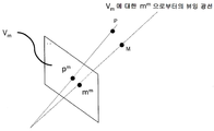
도 2 는 뷰 Vi 에 대한 카메라 투영을 나타내는 개략적 표현이고,
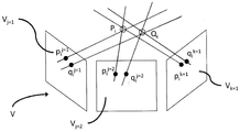
도 3 은 광 필드의 2D 뷰들에서 3 개의 위치 제약 파라미터들의 투영들을 도시하는 개략적 표현이며,
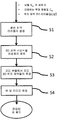
도 4는 본 발명의 일 실시형태들에 따른 방법을 수행할 때 구현되는 연속적인 단계들을 나타내는 흐름도이며,
도 5 는 본 발명의 일 실시형태에 따른 광 필드 데이터를 편집하기 위한 장치의 블록도이며,
도면들에서의 컴포넌트들은 반드시 일정한 것은 아니며, 대신 본 개시의 원리들을 설명할 때 강조된다.This disclosure can be better understood with reference to the following description and drawings which are given by way of example and do not limit the scope of protection.
1 is a schematic diagram illustrating the geometric warping of a 3D scene and corresponding 2D images,
2 is a schematic representation of a camera projection for view Vi,
3 is a schematic representation showing projections of three position constraint parameters in the 2D views of the light field,
4 is a flow chart illustrating successive steps implemented when performing a method according to one embodiment of the present invention,
5 is a block diagram of an apparatus for editing optical field data according to an embodiment of the present invention,
The components in the figures are not necessarily to scale, emphasis instead being placed upon illustrating the principles of the present disclosure.
본 개시의 특정 실시형태들의 일반적인 개념들 및 특정 세부사항들은 하기의 설명 및 도 1 내지 도 5 에서 설명되어 그러한 실시형태들의 완전한 이해를 제공한다. 그럼에도 불구하고, 본 개시는 추가의 실시형태들을 가질 수도 있거나, 또는 이하의 설명에서 설명되는 몇몇 세부사항들 없이 실시될 수도 있다.The general concepts and specific details of certain embodiments of the disclosure are set forth in the description that follows and in the figures of which provide a thorough understanding of such embodiments. Nevertheless, the present disclosure may have additional embodiments, or may be practiced without some of the details set forth in the following description.
1. 일반적인 개념들 및 전제 조건들1. General concepts and preconditions
본 발명은, 광 필드 캡처의 뷰들, 즉 참조 뷰들 중 일부에 관한 위치 제약들에 의해 명시된 기하학적 워프를 모든 뷰들에 전파하고, 각각의 뷰에 대해 워핑된 이미지를 생성하기 위한 방법을 설명하며, 그러한 방식으로 워핑된 이미지는 뷰들에 걸쳐 3D 에서 기하학적으로 일치한다.The present invention describes a method for propagating a geometric warp specified by position constraints on the views of an optical field capture, i.e., some of the reference views, to all views and generating a warped image for each view, Way warped images geometrically match in 3D across views.
도 1 에 의해 도시된 것과 같이, 광 필드는 장면이 캡처되는 뷰잉 각도를 샘플링하는 뷰들의 세트 V = {Vm} 에 의해 제공되는 것을 가정한다.As shown by FIG. 1, it is assumed that the light field is provided by a set of views V = {V m } that samples the viewing angle at which the scene is captured.
이러한 뷰들 (Vm) 의 세트 (V) 는 적어도 2 개의 참조 뷰들 (Vj) 및 적어도 하나의 추가 뷰 (Vk) 를 포함한다.The set V of these views V m includes at least two reference views V j and at least one additional view V k .
도 2 에 의해 도시된 것과 같이, 상기 뷰들의 세트 (V) 가 캘리브레이션된다고 추가로 가정하고, 이는 V 에서의 각각의 뷰 Vm 에 대해, 뷰에 대한 투영 행렬 (Cm) 이 알려진 것을 의미한다. Cm 은 3D 공간에서 임의의 포인트 P 의 뷰 Vm 로의 투영 (pm) 을 pm = CmP 로 계산하는 것을 허용한다. 반대로, 뷰 Vm 의 이미지 상에 임의의 포인트 mm 가 주어진 경우, Cm 은 뷰 Vm 에 대하여 mm 으로부터의 뷰잉 광선, 즉 뷰 Vm 에서 mm 상에 투영하는 3D 공간에서의 모든 포인트들 M 의 라인을 계산하는 것을 허용한다.As also shown by the two, it is assumed further that the set (V) of the view that the calibration, and which for each of the views V m in V, means that the projection matrix (C m) for the view-known . And C m is allowed to calculate the projection (p m) V m to the view of any point P in 3D space by p m = C m P. On the other hand, when any point m m given on the image of the view V m, C m is the viewing light from m m with respect to the view V m, that is, all the points in the 3D space to be projected on the view V m in m m Lt; RTI ID = 0.0 > M. ≪ / RTI >
최신 기술로 알려진, 뷰들에 대한 카메라 투영 행렬들을 계산하는 여러 가지 방식들, 캘리브레이션으로 알려진 프로세스가 존재한다.There are a number of ways to calculate camera projection matrices for views, known as the state of the art, processes known as calibration.
카메라 캘리브레이션에 대한 제 1 접근법은, 바둑판 패턴의 사각형들의 모서리들과 같은 용이하게 검출가능한 관심 포인트들로, 그리고 알려진 3D 지오메트리로, 장면에서 물체를 배치하는 것이다. 캘리브레이션 객체에서 관심 포인트들의 검출가능성은, 각 카메라 뷰 상의 2D 투영들을 강인하고 정확하게 발견하는 것을 허용한다. 이러한 대응들과 관심 포인트들의 3D 상대 포지션들의 정확한 지식을 통해, 내재 및 외인성 카메라 모델의 매개 변수를 데이터 피팅 절차로 계산할 수 있다. 이러한 일련의 방법들의 일 예가 R.Tsai, IEEE Journal on Robotics and Automation, Vols. RA-3, no. 4, pp. 323-344, 1987 에 의한 기사 "A Versatile Camera Calibration Technique for High-Accuracy 3D Machine Vision Metrology Using Off-The-Shelf TV Cameras and Lenses" 에 기술된다.The first approach to camera calibration is to place objects in the scene, with easily detectable points of interest, such as the corners of squares of a checkerboard pattern, and with known 3D geometry. The likelihood of detecting points of interest in the calibration object allows robust and accurate detection of 2D projections on each camera view. Through the knowledge of these correspondences and the exact 3D relative positions of the points of interest, parameters of the intrinsic and extrinsic camera models can be computed in a data fitting procedure. One example of such a set of methods is described in R. Tsai, IEEE Journal on Robotics and Automation, Vol. RA-3, no. 4, pp. 323-344, 1987, entitled " A Versatile Camera Calibration Technique for High-Accuracy 3D Machine Vision Metrology Using Off-The-Shelf TV Cameras and Lenses. &Quot;
카메라 캘리브레이션에 대한 제 2 접근법은, 뷰들의 쌍들, 즉 포인트들 (pi j, pi k) 의 쌍들 간의 2D 포인트 대응들의 세트를 입력으로 취하여, 뷰 Vj 에서의 pi j 와 뷰 Vk 에서의 pi k 이 동일한 3D 장면 포인트 Pi 의 투영들이 되게 한다. Z. Zhang, R. Deriche, O. Faugeras 및 n. Q.-T. Luo, Artificial Intelligence, vol. 78, no. 1-2, pp. 87-119, 1995. 에 의한 기사 "A Robust Technique for Matching Two Uncalibrated Images Through the Recovery of the Unknown Epipolar Geometry" 에 설명된 바와 같이, 뷰들의 쌍에 대한 기본 행렬은 적어도 여덟 (8) 개의 그러한 일치들이 알려질 경우 계산될 수 있음이 문헌으로부터 잘 알려져 있다. 뷰 Vm 에서 일부 3D 장면 포인트 M 의 투영 mm 이 주어지면, 기본 행렬은 이 뷰에서의 M 의 투영이 있어야만 하는 뷰 Vn 에서 mm 에 대한 등극선 (epipolar line) 을 정의한다. 카메라 사양들로부터 또는 지정된 캘리브레이션 절차로부터, 본질적인 카메라 파라미터들이 알려져 있다고 가정하면, 카메라들의 고려되는 쌍에 대한 카메라 투영 행렬들은 R. Hartley 및 A. Zisserman, Cambridge University Press Ed., 2003 에 의한 서적 "Multiple View Geometry in Computer Vision" 의 섹션 9 에서 설명된 것과 같이, 기본 행렬의 SVD 분해로부터 계산될 수 있다.The second approach to the camera calibration, the view pairs of, that is, points by taking a set of 2D points corresponding between pairs of (p i j, p i k) as an input, p i j in view V j and the view V k and the p i k will be in the same 3D scene point p i projection. Z. Zhang, R. Deriche, O. Faugeras and n. Q.-T. Luo, Artificial Intelligence, vol. 78, no. 1-2, pp. As described in the article "A Robust Technique for Matching Two Uncalibrated Images of Unknown Epipolar Geometry" , 87-119, 1995, the base matrix for a pair of views has at least eight (8) It is well known from the literature that it can be calculated if known. Given a projection m m of some 3D scene point M in view V m , the base matrix defines an epipolar line for m m in view V n where there must be projection of M in this view. From from the camera specifications or a specified calibration procedures, essentially assuming that the camera parameters are known, the camera projection matrix to be considered a pair of cameras R. Hartley and A. Zisserman, Cambridge University Press Ed. , According to the 2003 book "Multiple Can be calculated from the SVD decomposition of the base matrix, as described in
도 3 에 의해 도시된 바와 같이, 입력 데이터는 또한, 원래의 3D 장면의 소스 포인트 Pi 의, 및 워핑된 3D 장면에서의 대응하는 타겟 포인트 로케이션 Qi 의 참조 뷰 Vj 상의 투영들의 로케이션들을 각각 포함하는, 위치 제약 파라미터들 (pi j, qi j) 의 초기 세트 Sini 를 포함한다. 이러한 제약 파라미터 (pi j, qi j) 각각은 적어도 2 개의 참조 뷰들 Vj 에서 사용자에 의해 수동으로 지정된다. 적어도 하나의 추가 뷰 (Vk) 에서 동일한 3D 소스 포인트 (Pi) 및 3D 타겟 포인트 (Qi) 의 투영들에 적용될 기하학적 변환을 나타내는, 제약 파라미터들 (pi k, qi k) 의 세트 Sadd 는 입력 데이터의 일부가 아닌 것에 유의하여야 한다. 도 3 에서, 예시를 위해, 참조 뷰들이 표시되고 (Vj=1, Vj=2), 추가 뷰가 언급된다 (Vk=3). 참조 뷰들 Vj 에서 제공된 제약 파라미터들 (pi j, qi j) 은 참조 뷰들 Vj 에서의 투영들에 의해, 캡처된 장면의 대응하는 3D 포인트들에 적용될 기하학적 변환들을 나타낸다. 이들 대응하는 3D 포인트들에 기초하여, 본 발명에서 개시된 방법은 먼저, 제약 파라미터들 (pi k, qi k) 의 세트 Sadd 를 결정한다. 이 단계에 이어서, 추가 뷰들 Vk 의 제약 파라미터들 (pi k, qi k) 로 보완된, 참조 뷰들 Vj 의 제약 파라미터들 (pi j, qi j) 은 뷰들 Vm 의 각각에 적용될 제약 파라미터들 (pi m, qi m) 을 형성한다. 그 후, 방법은 이미지 워핑 변환들의 세트를 계산하고, 하나의 이미지 워핑 변환은 각각의 뷰 Vm 에 대해, 각각의 제약 파라미터들 (pi m, qi m) 에 따라, 뷰들 Vm 의 세트 V 에 걸쳐 뷰 이미지들을 일관되게 워핑한다.As shown by Figure 3, the input data also includes locations of the projections on the source point P i of the original 3D scene and on the reference view V j of the corresponding target point location Q i in the warped 3D scene, respectively And an initial set S ini of the position constraint parameters (p i j , q i j ), including: Each of these constraint parameters (p i j , q i j ) is manually specified by the user in at least two reference views V j . (P i k , q i k ) representing geometric transformations to be applied to projections of the same 3D source point (P i ) and 3D target point (Q i ) in at least one additional view (V k ) Note that S add is not part of the input data. In Figure 3, for reference, reference views are displayed ( Vj = 1 , Vj = 2 ) and an additional view is referred to ( Vk = 3 ). Reference pharmaceutical parameters provided by the views V j (p i j, q i j) represents the geometric transformation to be applied to corresponding 3D points of the captured scene by the projection of the reference views V j. Based on these corresponding 3D points, the method disclosed in the present invention first determines a set S add of the constraint parameters (p i k , q i k ). Following this step, the constraint parameters (p i j , q i j ) of the reference views V j supplemented with the constraint parameters (p i k , q i k ) of the further views V k are stored in each of the views V m To form the constraint parameters (p i m , q i m ) to be applied. The method then calculates a set of image warping transform, an image warping transformation in accordance with each of the constraint parameters (p i m, q i m) for each view, V m, a set of views V m V to warp view images consistently.
2. 하나의 특정 실시형태에 따라 광 필드 데이터를 일관되게 편집하기 위한 방법2. A method for consistently editing optical field data in accordance with one particular embodiment
도 4 에 도시된 바와 같이, 하나의 특정 실시형태에 따라 광 필드 데이터를 편집하는 방법은 적어도 네 (4) 개의 단계들을 포함한다:As shown in FIG. 4, a method for editing optical field data according to one specific embodiment includes at least four (4) steps:
● 적어도 2 개의 참조 뷰들 (Vj) 에서의 입력된 위치 제약 파라미터들 (pi j, qi j) 의 각각에 대해, 2D 소스 로케이션 (pi j) 상에 투영하는 3D 공간에서의 라인 및 2D 타겟 로케이션 (qi j) 상에 투영하는 3D 공간의 라인을 결정하는 단계 (S1),For each of the input position constraint parameters (p i j , q i j ) in the at least two reference views (V j ), a line in 3D space projecting onto the 2D source location (p i j ) Determining (S1) a line of 3D space to be projected on the 2D target location (q i j )
● 3D 장면에서, 2D 소스 로케이션 (pi j) 가 대응하는 뷰 (Vj) 로의 투영인 3D 소스 로케이션 (Pi), 및 3D 장면에서, 2D 타겟 로케이션 (qi j) 이 대응하는 뷰 (Vj) 로의 투영인 3D 소스 로케이션 (Qi) 을 결정하는 단계 (S2),● in the 3D scene, 2D source location (p i j) corresponds to the view (V j) projecting the 3D source location to that in (P i), and a 3D scene, 2D target location view corresponding to the (q i j) ( V j ), determining a 3D source location (Q i )
● 3D 소스 로케이션 (Pi) 및 상기 3D 타겟 로케이션 (Qi) 의 함수로서, 적어도 하나의 추가 뷰들 (Vk) 과 연관된 추가의 위치 제약 파라미터들 (pi k, qi k) 의 세트 Sadd 를 결정하는 단계 (S3), 쌍들 (pi k, qi k) 의 각각은 적어도 하나의 추가 뷰 (Vk) 에서 각각 Pi 및 Qi 의 투영들을 표현하고 상기 뷰를 워핑하기 위한 추가적인 위치 제약을 제공함,● 3D source set of location (P i) and the 3D target location as a function of (Q i), at least one additional views (V k) adding the location constraint parameters associated with the (p i k, q i k) S each step (S3), the pairs (p i k, q i k ) to determine the add is representing the projection of each p i and q i, in at least one additional views (V k) of the additional for warping the view Providing location constraints,
● 편집된 광 필드 데이터를 획득하기 위해, 대응하는 위치 제약 파라미터들 (pi m, qi m) 의 함수로서, 2D 뷰들의 세트 (Vm) 로부터 묘사된 3D 장면의 2D 이미지들의 각각을 워핑하는 단계 (S4).● to obtain the edited light field data, as a function of the corresponding position constraint parameter (p i m, q i m), warping each of the 2D image of the 3D scene depicted from the set (V m) of the 2D views (S4).
이들 스테이지들의 각각은 이하 더 상세히 설명된다.Each of these stages is described in more detail below.
단계 S1: 2D 제약 파라미터들 (pStep S1: 2D constraint parameters p ii jj , q, q ii jj ) 의 초기 세트 S) Initial set S iniini 에 대응하는 3D 장면 포인트들에 대한 광선 라인들의 생성 Lt; RTI ID = 0.0 > 3D < / RTI &
뷰 j 에서의 임의의 소스 또는 타겟 제약 포인트 pi j 는 pi j 가 투영인 3D 장면 포인트 Pi 가 있어야만 하는 3D 공간에서의 라인을 정의한다. 이 라인은 뷰 j 에서 투영들 pi j 이 주어지면, 3D 공간에서 Pi 의 로케이션을 제한한다. 그 방정식은 전제 조건들에서 가정한 대로, 각 뷰에 대해 사용가능한 캘리브레이션 데이터로부터 계산될 수 있다. 구체적으로, 3D 포인트 Pi 의 뷰 j 의 이미지 평면 상으로의 투영은 Pi 및 뷰 Vj 의 광학 중심을 통과하고, pi j 에서 뷰의 이미지 평면과 교차하는 광선에 의해 기하학적으로 모델링될 수 있다. 뷰 Vj 의 광학 중심이 카메라 투영 행렬 Cj 로부터 알려지기 때문에, 광선은 이 중심 및 Pi 를 통과하는 라인으로서 용이하게 계산될 수 있다.Any source or target constraint points p i j of the view j defines a line in 3D space that must have p i j is the projection of a 3D scene point P i. The lines are given by the view j is the projection p i j, and limits the location of the P i in the 3D space. The equation can be calculated from the calibration data available for each view, as assumed in the prerequisites. Specifically, the projection of the view point j of the 3D point P i onto the image plane can be geometrically modeled by the rays passing through the optical centers of P i and V j and intersecting the image plane of the view at p i j have. Since the optical center of view V j is known from the camera projection matrix C j , the ray can be easily calculated as a line passing through this center and P i .
3D 공간에서의 라인은 플루커 좌표들에서 d.m = 0 의 조건을 만족하는 한 쌍의 3D 벡터들 (d, m) = ((d1, d2, d3), (m1, m2, m3)) 로서 유리하게 표현될 수 있다. (di j, mi j) 가 Pi 와 pi j 를 통과하는 라인의 플루커 표현이라면, 뷰 j 상의 투영 pi j 에 의해 정의된 Pi 의 로케이션에 관한 광선 제약은 다음과 같이 표현될 수 있다:The line in 3D space is a pair of 3D vectors (d, m) = ((d 1 , d 2 , d 3 ), (m 1 , m 2 , m < 3 >). (d i j , m i j ) is a plucker representation of a line passing through P i and p i j , then the ray constraint on the location of P i defined by projection p i j on view j can be expressed as Can be:
![]()
![]()
단계 S2: 제약 파라미터들 (pStep S2: Constraining parameters p ii jj , q, q ii jj )로부터 3 차원 장면 좌표들 (PDimensional scene coordinates P ii , Q, Q ii ) 의 추정)
i 로 인덱싱된 임의의 (소스, 타겟) 제약 포인트의 로케이션은 적어도 두 (2) 개의 참조 뷰들을 포함하는 참조 뷰들 Vj 의 세트 Ri 에서 사용자에 의해 명시된다. Ri 의 각 참조 뷰 Vj 에서 소스 제한 포인트 Pi 의 투영 pi j 의 알려진 로케이션은 pi j 가 투영들인 소스 장면 포인트 Pi 에 대해, 단계 S1 에서 계산된 광선 제약들의 세트를 정의한다. 유사하게, Ri 의 각 뷰 Vj 에서 타겟 제한 포인트 Qi 의 투영 qi j 의 알려진 로케이션은 qi j 가 투영들인 타겟 장면 포인트 Qi 에 대해, 단계 S1 에서 계산된 광선 제약들의 세트를 정의한다.The location of any (source, target) constraint point indexed with i is specified by the user in a set R i of reference views V j containing at least two (2) reference views. The known location of the projection p i j of the source restriction point P i in each reference view V j of R i defines a set of ray constraints calculated in
제약 포인트들에 연관된 장면 포인트들 Pi 및 Qi 의 각각의 로케이션은 최소 제곱법의 관점에서 참조 뷰들 Vj 의 세트 Ri 에 대한 광선 제약들에 의해 형성된 연립 방정식을 푸는 것에 의해 추정된다:The location of each of the scene points P i and Q i associated with the constraint points is estimated by solving the simultaneous equations formed by the ray constraints for the set R i of the reference views V j in terms of least squares:

이 연립방정식은 표준 2 차 프로그래밍 기법들에 의해 풀이될 수 있다.This simultaneous equation can be solved by standard secondary programming techniques.
장면 포인트들의 변형에 관한 사용가능한 이전 것들이 이 스테이지에서 도입될 수 있다. 예를 들어, 대응하는 3D 소스 포인트 Pi (플루커 좌표들 (di, mi) 로 표현됨) 와 타겟 포인트 Qi (플루커 좌표들 (d'i, m'i) 로 표현됨) 의 각 쌍 간의 거리들이 가능한 한 일정하다는 것을 부과함으로써 원래의 3D 장면의 지오메트리를 보존하는 것을 원할 수도 있다. 2D 위치 제약들에 연관된 장면 포인트들의 로케이션들의 추정치들은 예를 들어, 다음 기준을 최소화함으로써 전역적으로 수행되어야만 한다:Usable prior art about deformation of scene points can be introduced in this stage. For example, the angle of the corresponding 3D source point P i (represented by the pluctor coordinates d i , m i ) and the target point Q i (represented by the pluctor coordinates d ' i , m' i ) You may want to preserve the geometry of the original 3D scene by imposing the constant distance between pairs as possible. Estimates of locations of scene points associated with 2D position constraints must be performed globally, for example, by minimizing the following criteria:

이 최적화 문제는 Gauss-Newton 최소화와 같은 표준 수치 최적화 기법들에 의해 수행될 수 있고, 이는 미지수들에 대해 최소화될 함수의 도함수들이 닫힌 형식 (closed form) 으로 사용가능하기 때문이다.This optimization problem can be performed by standard numerical optimization techniques such as Gauss-Newton minimization because the derivatives of the function to be minimized to unknowns can be used in a closed form.
단계 S3: 각 추가 뷰 (VStep S3: Each additional view (V kk ) 에서 위치 제약 파라미터들 (p), The position constraint parameters p ii kk , q, q ii kk ) 의 새로운 세트 (SNew set of addadd ) 의 생성)
기하학적 워프의 사양을 정의하는 위치 제약들의 각각은 초기에 광 필드 뷰들의 서브세트 Ri 에서 사용자에 의해 명시되었다. 단계 S2 에서 계산된 각각의 3D 제약 포인트 Pi 의 Ri 를 제외한 V 에서의 임의의 추가적인 뷰 Vk 로의 2D 투영들 pi k 은 캘리브레이션 데이터로부터 알려진 뷰 카메라 투영 행렬들 {Ck} 을 사용하여 결정될 수 있다:Each of the position constraints defining the geometric warp specification was initially specified by the user in a subset R i of the optical field views. The 2D projections p i k to any additional view V k at V except for R i of each 3D constraint point P i computed in
![]()
![]()
따라서, 단계 S3 의 출력에서, 참조 뷰들 (Vj) 의 서브세트들 Ri 에서 사용자에 의해 초기에 지정된 소스 및 타겟 로케이션 제약 파라미터들의 2D 투영들 (pi j, qi j) 이 모든 뷰들에서 알려져 있다.Thus, at the output of step S3, the 2D projections (p i j , q i j ) of the source and target location constraint parameters initially specified by the user in subsets R i of the reference views (V j ) It is known.
단계 4: 제약 파라미터들 (pStep 4: Constraint parameters p ii mm , q, q ii mm ) 을 적용하는 것에 의한 각각의 뷰 (V(V) < / RTI > by applying < RTI ID = 0.0 & mm ) 의 워핑) Warping
N 개의 상이한 (소스 Pi, 타겟 Qi) 위치 제약들이 초기에 참조 뷰들의 부분세트들 Ri 에서 그들의 투영들 (pi j, qi j) 을 통해 사용자에 의해 명시되었다고 가정한다. 단계 S3 다음에, 위치 제약 파라미터들의 1≤i≤N 에 대한 투영들 (pi j, qi j) 이 지금부터 모든 뷰들 (Vm) 에 대해 알려져 있다. 그 후, 최적의 워핑 변환 Mx m 은 뷰에서의 위치 제약들의 투영들 (pi m, qi m) 에 기초하여, 뷰의 모든 픽셀에 대해, 각각의 뷰 Vm 에서 독립적으로 계산된다.It is assumed that N different (source P i , target Q i ) position constraints are initially specified by the user through their projections (p i j , q i j ) in the subset of reference views R i . After step S3, projections (p i j , q i j ) for 1? I? N of position constraint parameters are known for all views (V m ) from now on. The optimal warping transform M x m is then computed independently for each of the views V m for all the pixels of the view, based on the projections (p i m , q i m ) of the position constraints in the view.
Mx m 의 계산은 최적화 기준 및 변환을 위한 모델의 선택에 따라, 다양한 형태들을 취할 수도 있다. 유리하게, S. Schaefer, T. McPhail 및 J. Warren, in SIGGRAPH, 2006 에 의한 기사 "Image deformation using moving least squares" 에서 제안된 Mx 에 대한 이동 최소 제곱 에너지들 및 연관된 제한된 아핀 모델들 중 하나는, Mx m 을 계산하기 위해 사용된다. 예를 들어, Mx m 은 선형 변환 Ax m 및 트랜스레이션 Tx m 으로 구성된 아핀 변환이 되도록 선택되고:The calculation of M x m may take various forms, depending on the optimization criteria and the choice of model for the transformation. Advantageously, the moving least-squares energies for M x proposed in the article "Image deformation using moving least squares" by S. Schaefer, T. McPhail and J. Warren, in SIGGRAPH, 2006 and one of the associated limited affine models Is used to calculate M x m . For example, M x m is chosen to be an affine transformation consisting of a linear transformation A x m and a transformation T x m :
![]()
![]()
pi m 과 상이한 모든 포인트 x 에 대하여 다음의 최적화 문제에 대한 솔루션으로서 정의된다:For every point x different from p i m it is defined as a solution to the following optimization problem:

Mpim ( pi m ) 은 qi m 과 동일한 것으로 정의된다. 위의 방정식에서 우측 항을 최소화하는 것은 2 차 프로그래밍 문제이며, 그 솔루션은 최신 기술에서 잘 알려진 기법들을 사용하여 획득될 수 있다.M pim (p i m ) is defined to be equal to q i m . Minimizing the right term in the above equation is a secondary programming problem, and the solution can be obtained using techniques well known in the state of the art.
본 발명은 워핑 모델 및 최적성 기준의 상기 선택에 제한되지 않는다. 예를 들어, 기사 "Bounded Biharmonic Weights for Real-Time Deformation," A. Jacobson, I. Baran, J. Popovic 및 O. Sorkine, in SIGGRAPH, 2011 에서 제안된 바운딩된 이중 조화 가중 워핑 모델은 이동 최소 제곱 알고리즘 대신 사용될 수 있다. 이러한 접근법에서, 전체 이미지가 각각의 사용자-지정 위치 제약에 연관되는 아핀 변환 및 이미지 워프는 이들 아핀 변환들의 선형 조합으로서 계산된다. 최적의 워핑 변환은, 선형 조합의 가중치들이 몇몇 제약들의 대상이 되는 이미지에 걸쳐 가능한 한 일정한 것으로 정의된다. 특히, 각 위치 제약의 로케이션에서의 워프는 제약 조건과 연관된 아핀 변환과 일치하도록 강제된다. 결과적인 최적화 문제는 유한 요소 모델링을 사용하여 불연속화되고 희소 2 차 프로그래밍을 사용하여 풀이된다.The present invention is not limited to the above selection of warping model and optimality criterion. For example, the bounded dual harmonic weighted warping model proposed in the article "Bounded Biharmonic Weights for Real-Time Deformation," A. Jacobson, I. Baran, J. Popovic and O. Sorkine, in SIGGRAPH, Algorithm can be used instead. In this approach, affine transformation and image warping, in which the entire image is associated with a respective user-specified position constraint, are computed as a linear combination of these affine transformations. The optimal warping transformation is defined as being as constant as possible over the image for which the weights of the linear combination are subject to some constraints. In particular, the warp at the location of each location constraint is forced to coincide with the affine transformation associated with the constraint. The resulting optimization problem is discretized using finite element modeling and solved using sparse quadratic programming.
이중 조화 워핑 모델은 각각의 위치 제약의 로케이션에서 아핀 변환이 명시될 것을 필요로 한다. 제 1 옵션은 이 아핀 변환을 소스로부터 타겟 제한 포인트로의 지정된 변환으로 제한하는 것이다. 대안적으로, 아핀 변환은 피팅에 대한 제약들로서 모든 다른 이용가능한 위치 제약들을 사용하여, 고려된 로케이션에 대한 아핀 변환을 최소 제곱 적합 (least-squares fitting) 함으로써 계산될 수 있다.The dual harmonic warping model requires the affine transformation to be specified at the location of each position constraint. The first option is to limit this affine transform to the specified transform from the source to the target limit point. Alternatively, the affine transformation can be computed by least-squares fitting the affine transformation on the considered location, using all other available position constraints as constraints on the fitting.
3. 광 필드 데이터를 일관되게 편집하기 위한 장치의 설명.3. A description of the device for consistently editing optical field data.
도 5 는 본 개시의 일 실시형태에 따른 광 필드 데이터를 편집하기 위한 장치 (1) 의 일 예를 도시하는 개략적인 블록도이다. 이러한 장치 (1) 는 버스 (5) 에 의해 접속된 프로세서 (2), 저장 유닛 (3) 및 인터페이스 유닛 (4) 을 포함한다. 물론, 컴퓨터 장치 (1) 의 구성 엘리먼트들은 버스 (5) 를 사용하는 버스 접속 이외의 접속에 의해 접속될 수도 있다.5 is a schematic block diagram showing an example of an
프로세서 (2) 는 장치 (1) 의 동작을 제어한다. 저장 유닛 (3) 은 프로세서 (2) 에 의해 실행될 적어도 하나의 프로그램과, 광 필드 데이터, 프로세서 (2) 에 의해 수행된 계산들에 의해 사용되는 파라미터들, 프로세서 (2) 에 의해 수행된 계산들의 중간 데이터 등을 포함하는 다양한 데이터를 저장한다. 프로세서 (2) 는 임의의 공지되고 적합한 하드웨어, 또는 소프트웨어, 또는 하드웨어와 소프트웨어의 조합에 의해 형성될 수도 있다. 예를 들어, 프로세서 (2) 는 프로세싱 회로와 같은 전용 하드웨어에 의해, 또는 그 메모리에 저장된 프로그램을 실행하는 CPU (Central Processing Unit) 와 같은 프로그래밍가능 프로세싱 유닛에 의해 형성될 수도 있다.The
저장 유닛 (3) 은 프로그램, 데이터 등을 컴퓨터 판독가능 방식으로 저장할 수 있는 임의의 적절한 스토리지 또는 수단에 의해 형성될 수도 있다. 저장 유닛 (3) 의 예들은 반도체 메모리 디바이스들과 같은 비-일시적 컴퓨터 판독가능 저장 매체 및 판독 및 기록 유닛에 로딩된 자기, 광학 또는 광자기 기록 매체를 포함한다. 프로그램은 프로세서 (2) 가 도 4 를 참조하여 전술된 것과 같이 본 개시의 일 실시형태에 따라 광 필드 데이터를 편집하기 위한 프로세스를 수행하게 한다.The
인터페이스 유닛 (4) 은 장치 (1) 와 외부 장치 사이의 인터페이스를 제공한다. 인터페이스 유닛 (4) 은 케이블 또는 무선 통신을 통해 외부 장치와 통신할 수도 있다. 이 실시형태에서, 외부 장치는 광 필드 캡처 디바이스 (6) 일 수도 있다. 이 경우, 광 필드 데이터는 인터페이스 유닛 (4) 을 통해 플렌옵틱 카메라로부터 장치 (1) 로 입력되고, 그 후에 저장 유닛 (3) 에 저장될 수 있다.The
장치 (1) 및 플렌옵틱 카메라는 케이블 또는 무선 통신을 통해 서로 통신할 수도 있다.The
장치 (1) 는 디스플레이 디바이스를 포함할 수도 있거나, 또는 하나 또는 몇몇의 워핑된 2D 이미지들을 디스플레이하기 위한 임의의 디스플레이 디스플레이에 통합될 수도 있다.The
장치 (1) 는 또한, 사용자가 위치 제약 파라미터들 (pi j, qi j) 의 적어도 하나의 초기 세트 (Sini) 를 입력하게 하도록 구성된 인간/기계 인터페이스 (7) 를 포함할 수도 있다.The
오직 하나의 프로세서 (2) 가 도 5 에 도시되지만, 당업자는 그러한 프로세서가 본 개시의 실시형태들에 따라 장치 (1) 에 의해 실행되는 기능들을 구현하는 상이한 모듈들 및 유닛들을 포함할 수도 있음을 이해할 것이며, 예컨대:Although only one
● 적어도 2 개의 참조 뷰들 (Vj) 에서의 입력된 위치 제약 파라미터들 (pi j, qi j) 의 각각에 대해, 2D 소스 로케이션 (pi j) 상에 투영하는 3D 공간에서의 라인 및 2D 타겟 로케이션 (qi j) 상에 투영하는 3D 공간에서의 라인을 결정 (S1) 하기 위한 모듈,For each of the input position constraint parameters (p i j , q i j ) in the at least two reference views (V j ), a line in 3D space projecting onto the 2D source location (p i j ) A module for determining a line (S1) in a 3D space to be projected on a 2D target location (q i j )
● 3D 장면에서, 2D 소스 로케이션 (pi j) 가 대응하는 뷰 (Vj) 로의 투영인 3D 소스 로케이션 (Pi) 및 3D 장면에서, 2D 타겟 로케이션 (qi j) 가 대응하는 뷰 (Vj) 로의 투영인 3D 타겟 로케이션 (Qi) 를 결정 (S2) 하기 위한 모듈,● In a 3D scene, in a 3D source location (P i ) and a 3D scene where a 2D source location (p i j ) is a projection to a corresponding view (V j ), a 2D target location (q i j ) the projection to j) 3D target location (module for determining (S2) a Q i),
● 3D 소스 로케이션 (Pi) 및 상기 3D 타겟 로케이션 (Qi) 의 함수로서, 적어도 하나의 추가 뷰들 (Vk) 과 연관된 추가의 위치 제약 파라미터들 (pi k, qi k) 의 세트를 결정 (S3) 하기 위한 모듈, 쌍들 (pi k, qi k) 의 각각은 적어도 하나의 추가 뷰 (Vk) 에서 각각 Pi 및 Qi 의 투영들을 표현하고 상기 뷰를 워핑하기 위한 추가적인 위치 제약을 제공함,● the 3D source location (P i) and the set of the 3D target location as a function of (Q i), at least one additional views (V k) adding the location constraint parameters associated with the (p i k, q i k ) Each of the pairs (p i k , q i k ) for determining (S3) represents the projections of P i and Q i respectively in at least one additional view (V k ) Providing constraints,
● 편집된 광 필드 데이터를 획득하기 위해, 대응하는 위치 제약 파라미터들 (pi m, qi m) 의 함수로서, 2D 뷰들의 세트 (Vm) 로부터 묘사된 3D 장면의 2D 이미지들의 각각을 워핑 (S4) 하기 위한 모듈.● to obtain the edited light field data, as a function of the corresponding position constraint parameter (p i m, q i m), warping each of the 2D image of the 3D scene depicted from the set (V m) of the 2D views (S4).
이들 모듈은 또한, 서로 통신하고 상호 작용하는 여러 프로세서들 (2) 로 구현될 수도 있다.These modules may also be implemented with
당업자가 인식하는 것과 같이, 본 원리들의 양태들은 시스템, 방법 또는 컴퓨터 판독가능 매체로서 구현될 수 있다. 따라서, 본 원리들의 양태들은 전적으로 하드웨어 실시형태, 전적으로 소프트웨어 실시형태 (펌웨어, 상주 소프트웨어, 마이크로 코드, 등을 포함 함), 또는 소프트웨어 및 하드웨어 양태들을 결합한 실시형태의 형태를 취할 수 있다.As those skilled in the art will appreciate, aspects of the present principles may be implemented as a system, method, or computer readable medium. Accordingly, aspects of the present principles may take the form of an entirely hardware embodiment, an entirely software embodiment (including firmware, resident software, microcode, etc.), or an embodiment combining software and hardware aspects.
본 원리들이 하나 또는 몇몇의 하드웨어 컴포넌트들 의해 구현되는 경우, 하드웨어 컴포넌트는 중앙 프로세싱 유닛 및/또는 마이크로프로세서와 같은 집적 회로, 및/또는 ASIC (Application-specific integrated circuit), 및/또는 ASIP (Application-specific instruction-set processor), 및/또는 GPU (graphics processing unit), 및/또는 PPU (physics processing unit), 및/또는 DSP (digital signal processor), 및/또는 이미지 프로세서, 및/또는 코프로세서, 및/또는 부동 소수점 유닛, 및/또는 네트워크 프로세서, 및/또는 오디오 프로세서, 및/또는 멀티 코어 프로세서인 프로세서를 포함하는 것에 유의할 수 있다. 또한, 하드웨어 컴포넌트는 또한, 무선 신호들을 수신 또는 송신하는 베이스밴드 프로세서 (예를 들어, 메모리 유닛들 및 펌웨어를 포함함) 및/또는 무선 전자 회로들 (안테나들을 포함할 수 있음) 을 포함할 수 있다. 일 실시형태에서, 하드웨어 컴포넌트는 ISO/IEC 18092 / ECMA-340, ISO/IEC 21481 / ECMA-352, GSMA, StoLPaN, ETSI / SCP (스마트 카드 플랫폼), GlobalPlatform (즉, 보안 엘리먼트) 와 같은 하나 이상의 표준들에 부합한다. 일 변형에서, 하드웨어 컴포넌트는 무선 주파수 식별 (RFID) 태그이다. 일 실시형태에서, 하드웨어 컴포넌트는 블루투스 통신들, 및/또는 Wi-fi 통신들, 및/또는 Zigbee 통신들, 및/또는 USB 통신들, 및/또는 Firewire 통신들 및/또는 (근거리장 용의) NFC 통신들을 가능하게 하는 회로들을 포함한다.When these principles are implemented by one or several hardware components, the hardware components may be integrated circuits such as central processing units and / or microprocessors, and / or application-specific integrated circuits (ASICs) and / specific instruction-set processor, and / or a graphics processing unit (GPU), and / or a physics processing unit (PPU), and / or a digital signal processor (DSP), and / or an image processor, and / And / or a floating-point unit, and / or a network processor, and / or an audio processor, and / or a multi-core processor. The hardware components may also include a baseband processor (e.g., including memory units and firmware) and / or wireless electronic circuits (which may include antennas) that receive or transmit wireless signals have. In one embodiment, the hardware components may be one or more of the following: ISO / IEC 18092 / ECMA-340, ISO / IEC 21481 / ECMA-352, GSMA, StoLPaN, ETSI / SCP (smart card platform), GlobalPlatform Standards. In one variation, the hardware component is a radio frequency identification (RFID) tag. In one embodiment, the hardware component may include Bluetooth communications, and / or Wi-fi communications, and / or Zigbee communications, and / or USB communications, and / or Firewire communications and / And circuits that enable NFC communications.
또한, 본 원리들의 양태들은 컴퓨터 판독가능 저장 매체의 형태를 취할 수 있다. 하나 이상의 컴퓨터 판독가능 저장 매체(들)의 임의의 조합이 활용될 수도 있다.In addition, aspects of the present principles may take the form of computer-readable storage media. Any combination of one or more computer-readable storage medium (s) may be utilized.
따라서, 예를 들어, 임의의 플로우 차트들, 플로우 다이어그램들, 상태 천이 다이어그램들, 의사코드 등은, 컴퓨터 판독가능 매체에 실질적으로 표현되고 따라서 컴퓨터 또는 프로세서에 명시적으로 나타나든지 아니든지 그러한 컴퓨터 또는 프로세서에 의해 실행될 수도 있는 다양한 프로세스들을 표현함이 인식될 것이다.Thus, for example, any flowcharts, flow diagrams, state transition diagrams, pseudocode, etc. may be stored on a computer readable medium, whether substantially represented in a computer readable medium, It will be appreciated that a variety of processes may be executed by the processor.
본 개시가 하나 이상의 예들을 참조하여 설명되었지만, 당업자는 본 개시 및/또는 첨부된 청구 범위의 범위를 벗어나지 않는 형태 및 세부 사항에서 변경들이 이루어질 수도 있음을 인식할 것이다.While this disclosure has been described with reference to one or more examples, those skilled in the art will recognize that changes may be made in form and detail without departing from the scope of the disclosure and / or the appended claims.
Claims (15)
상기 방법은,
● 2D 뷰들 (Vm) 의 세트 (V) 로부터 묘사된 3D 장면의 복수의 캘리브레이션된 2D 이미지들을 포함하는 광 필드 데이터로서, 상기 2D 뷰들 (Vm) 의 세트 (V) 는 적어도 2 개의 참조 뷰들 (Vj) 및 적어도 하나의 추가 뷰 (Vk) 를 포함하는, 상기 광 필드 데이터,
● 상기 적어도 2 개의 참조 뷰들 (Vj) 과 연관된 위치 제약 파라미터들 (pi j, qi j) 의 적어도 하나의 초기 세트로서, 상기 위치 제약 파라미터들 (pi j, qi j) 의 각각은 원래의 2D 이미지를 워핑하기 위해, 상기 적어도 2 개의 참조 뷰들 (Vj) 중에서, 대응하는 뷰 (Vj) 로부터 묘사된 상기 3D 장면의 상기 원래의 2D 이미지에서의 주어진 포인트에 적용될 변환을 표현하고, 상기 위치 제약 파라미터들 (pi j, qi j) 은,
○ 상기 대응하는 뷰 (Vj) 로부터 묘사된 상기 3D 장면의 상기 원래의 2D 이미지에서의 주어진 포인트의, 상기 대응하는 뷰 (Vj) 에서의 2D 소스 로케이션 (pi j),
○ 상기 대응하는 뷰 (Vj) 로부터 묘사된 상기 3D 장면의 워핑된 2D 이미지에서의 주어진 포인트의, 상기 대응하는 뷰 (Vj) 에서의 2D 타겟 로케이션 (qi j)
을 포함하는, 상기 위치 제약 파라미터들 (pi j, qi j) 의 적어도 하나의 초기 세트
를 프로세싱하고,
상기 방법은,
● 상기 적어도 2 개의 참조 뷰들과 연관된 상기 위치 제약 파라미터들 (pi j, qi j) 의 각각에 대해, 상기 3D 장면에서, 상기 2D 소스 로케이션 (pi j) 이 상기 대응하는 뷰 (Vj) 로의 투영인 3D 소스 로케이션 (Pi) 및 상기 3D 장면에서, 상기 2D 타겟 로케이션 (qi j) 이 상기 대응하는 뷰 (Vj) 로의 투영인 3D 타겟 로케이션 (Qi) 을 결정하는 단계 (S2),
● 상기 3D 소스 로케이션 (Pi) 과 상기 3D 타겟 로케이션 (Qi) 의 함수로서, 상기 적어도 하나의 추가 뷰들 (Vk) 와 연관된 추가의 위치 제약 파라미터들 (pi k, qi k) 의 추가의 세트를 결정하는 단계 (S3) 로서, 상기 추가의 위치 제약 파라미터들 (pi k, qi k) 의 각각은 상기 원래의 2D 이미지를 워핑하기 위해, 상기 적어도 하나의 추가 뷰 (Vk) 중에서, 대응하는 뷰 (Vk) 로부터 묘사된 3D 장면의 원래의 2D 이미지에서 주어진 포인트에 적용될 변환을 표현하는, 상기 추가의 위치 제약 파라미터들 (pi k, qi k) 의 추가의 세트를 결정하는 단계 (S3),
● 편집된 광 필드 데이터를 획득하기 위해, 상기 2D 뷰들과 연관된 상기 위치 제약 파라미터들 (pi m, qi m) 의 함수로서, 상기 2D 뷰들 (Vm) 의 세트로부터 묘사된 상기 3D 장면의 상기 2D 이미지들의 각각을 워핑하는 단계 (S4)
를 포함하는, 광 필드 데이터를 일관되게 편집하기 위한 방법.As a method for consistently editing optical field data,
The method comprises:
● 2D views (V m) the set (V), the set (V) of the 2D views (V m) as a light field data, including a plurality of calibration 2D image of a 3D scene depicted from at least two reference views (V j ) and at least one additional view (V k ).
● each, each of the location constraint parameter (p i j, q i j) as at least one initial set of the at least two reference views the position constraint parameters associated with the (V j) (p i j , q i j) Represents a transformation to be applied to a given point in the original 2D image of the 3D scene depicted from a corresponding view (V j ), of the at least two reference views (V j ), to warp the original 2D image , And the position constraint parameters (p i j , q i j )
○ the response of the 3D of the original for a given point in a 2D image of the scene, 2D source location in the view (V j) to the corresponding (p i j) depicted from the view (V j) which,
○ 2D target location at a given point in the 3D of the warped 2D image of a scene, a view (V j) and the corresponding depicted from the view (V j) and the corresponding (q i j)
At least one initial set of position constraint parameters (p i j , q i j )
Lt; / RTI >
The method comprises:
● For each of the at least two of said position constraint parameters associated with the two reference views (p i j, q i j), in the 3D scene, the 2D source location (p i j) the view (V j and the corresponding (P i ) that is a projection to the corresponding view (V j ) and a 3D target location (Q i ) in which the 2D target location (q i j ) is the projection to the corresponding view S2),
● the 3D source location (P i) and the 3D target location as a function of (Q i), the at least one additional views (V k) adding the location associated with the constraint parameter (p i k, q i k ) of Wherein each of the additional position constraint parameters (p i k , q i k ) is determined for each of the at least one additional view (V k , q i k ) to warp the original 2D image (P i k , q i k ) representing the transformation to be applied to a given point in the original 2D image of the 3D scene depicted from the corresponding view (V k ) (S3), < / RTI >
(V m ) as a function of said position constraint parameters (p i m , q i m ) associated with said 2D views to obtain edited light field data Warping each of the 2D images (S4)
Gt; a < / RTI > method for consistently editing light field data.
상기 3D 장면의 상기 복수의 캘리브레이션된 2D 이미지들은 상기 2D 뷰들 (Vm) 의 각각에 대한 상기 3D 장면의 대응하는 투영 행렬들 (Cm) 의 세트로부터 추가로 묘사되는, 광 필드 데이터를 일관되게 편집하기 위한 방법.The method according to claim 1,
Wherein the plurality of calibrated 2D images of the 3D scene are consistently represented by a set of corresponding projection matrices (C m ) of the 3D scene for each of the 2D views (V m ) How to edit.
상기 위치 제약 파라미터들 (pi j, qi j) 의 상기 적어도 하나의 초기 세트를 입력하는 사전 단계를 포함하는, 광 필드 데이터를 일관되게 편집하기 위한 방법.3. The method according to claim 1 or 2,
Inputting the at least one initial set of position constraint parameters (p i j , q i j ).
상기 적어도 2 개의 참조 뷰들 (Vj) 과 연관된 상기 위치 제약 파라미터들 (pi j, qi j) 의 각각에 대해, 상기 2D 소스 로케이션 (pi j) 상에 투영하는 3D 공간에서의 라인, 및 상기 2D 타겟 로케이션 (qi j) 상에 투영하는 3D 공간에서의 라인을 결정하는 단계 (S1), 및 상기 3D 소스 로케이션 및 상기 3D 타겟 로케이션을 상기 라인들로부터 결정하는 단계를 포함하는, 광 필드 데이터를 일관되게 편집하기 위한 방법.4. The method according to any one of claims 1 to 3,
For each of the position constraint parameters (p i j , q i j ) associated with the at least two reference views (V j ), a line in 3D space projecting onto the 2D source location (p i j ) And determining a line in a 3D space to project on the 2D target location (q i j ), and determining the 3D source location and the 3D target location from the lines. A method for consistently editing field data.
각 라인은 플루커 (Pluecker) 좌표들에서 (d, m) 으로 표시된 한 쌍의 3D 벡터들로 표현되고, 상기 3D 장면에서, 상기 2D 소스 로케이션 (pi j) 이 상기 대응하는 뷰 (Vj) 로의 투영인 상기 3D 소스 로케이션 (Pi) 을 결정하는 단계 (S2) 는, 최소 제곱법의 관점에서, 위치 제약들 (pi j, qi j) 의 초기 세트에 의해 형성된 연립 방정식을 푸는 단계를 포함하는, 광 필드 데이터를 일관되게 편집하기 위한 방법:

Each line fluorenyl large (Pluecker) in the coordinates is represented by (d, m) of a pair of 3D vector shown, in the 3D scene, the 2D source location (p i j) the view (V j and the corresponding ) step (S2) of determining the said 3D source location (P i) projected to have, in terms of the least squares method, solving the system of equations formed by the initial set of location restrictions (p i j, q i j) A method for consistently editing light field data, comprising:
상기 워핑하는 단계 (S4) 는 이동 최소 제곱 알고리즘을 구현하는, 광 필드 데이터를 일관되게 편집하기 위한 방법.6. The method according to any one of claims 1 to 5,
Wherein said warping step (S4) implements a moving least squares algorithm.
상기 워핑하는 단계 (S4) 는 하나의 아핀 변환이 각각의 위치 제약에 부가되는, 아핀 변환들의 세트의 함수로서 정의된 바운드된 이중 조화 가중 워핑 모델 (bounded biharmonic weights warping model) 을 구현하는, 광 필드 데이터를 일관되게 편집하기 위한 방법.6. The method according to any one of claims 1 to 5,
The step of warping S4 comprises the steps of applying a bounded biharmonic weights warping model defined as a function of a set of affine transformations, wherein one affine transformation is added to each position constraint, A method for consistently editing data.
각각의 위치 제약에 대해 상기 아핀 변환을 입력하는 사전 단계를 포함하는, 광 필드 데이터를 일관되게 편집하기 위한 방법.8. The method of claim 7,
And inputting the affine transformation for each location constraint. ≪ Desc / Clms Page number 19 >
모든 다른 위치 제약 파라미터들 (pi j, qi j) 로부터, 포인트의 로케이션에서의 아핀 변환을 최소 제곱 적합 (least-squares fitting) 함으로써, 각 위치 제약에 대한 아핀 변환을 결정하는 사전 단계를 포함하는, 광 필드 데이터를 일관되게 편집하기 위한 방법.8. The method of claim 7,
Includes a preliminary step of determining the affine transformation for each position constraint by least-squares fitting the affine transformation at the location of the point from all other position constraint parameters (p i j , q i j ) A method for consistently editing light field data.
상기 3D 장면의 워핑된 2D 이미지들 중 적어도 하나를 렌더링하는 단계를 포함하는, 광 필드 데이터를 일관되게 편집하기 위한 방법.10. The method according to any one of claims 1 to 9,
And rendering at least one of the warped 2D images of the 3D scene.
● 상기 광 필드 데이터는 2D 뷰들 (Vm) 의 세트로부터 묘사된 3D 장면의 복수의 캘리브레이션된 2D 이미지들을 포함하고, 상기 2D 뷰들 (Vm) 의 세트는 적어도 2 개의 참조 뷰들 (Vj) 및 적어도 하나의 추가 뷰 (Vk) 를 포함하며,
● 위치 제약 파라미터들 (pi j, qi j) 의 적어도 하나의 초기 세트가 상기 적어도 2 개의 참조 뷰들 (Vj) 과 연관되며, 상기 위치 제약 파라미터들 (pi j, qi j) 의 각각은 원래의 2D 이미지를 워핑하기 위해, 상기 적어도 2 개의 참조 뷰들 (Vj) 중에서, 대응하는 뷰 (Vj) 로부터 묘사된 3D 장면의 상기 원래의 2D 이미지에서의 주어진 포인트에 적용될 변환을 표현하고, 상기 위치 제약 파라미터들 (pi j, qi j) 은,
○ 상기 대응하는 뷰 (Vj) 로부터 묘사된 상기 3D 장면의 상기 원래의 2D 이미지에서의 주어진 포인트의, 상기 대응하는 뷰 (Vj) 에서의 2D 소스 로케이션 (pi j),
○ 상기 대응하는 뷰 (Vj) 로부터 묘사된 상기 3D 장면의 워핑된 2D 이미지에서의 주어진 포인트의, 상기 대응하는 뷰 (Vj) 에서의 2D 타겟 로케이션 (qi j)
으로 구성되며,
상기 장치 (1) 는 프로세서 (2) 를 포함하고,
상기 프로세서 (2) 는,
● 상기 적어도 2 개의 참조 뷰들과 연관된 상기 위치 제약 파라미터들 (pi j, qi j) 의 각각에 대해, 상기 3D 장면에서, 상기 2D 소스 로케이션 (pi j) 이 상기 대응하는 뷰 (Vj) 로의 투영인 3D 소스 로케이션 (Pi) 및 상기 3D 장면에서, 상기 2D 타겟 로케이션 (qi j) 이 상기 대응하는 뷰 (Vj) 로의 투영인 3D 타겟 로케이션 (Qi) 을 결정 (S2) 하고,
● 상기 3D 소스 로케이션 (Pi) 과 상기 3D 타겟 로케이션 (Qi) 의 함수로서, 상기 적어도 하나의 추가 뷰들 (Vk) 과 연관된 추가의 위치 제약 파라미터들 (pi k, qi k) 의 추가의 세트를 결정 (S3) 하는 것으로서, 상기 추가의 위치 제약 파라미터들 (pi k, qi k) 의 각각은 상기 원래의 2D 이미지를 워핑하기 위해, 상기 적어도 하나의 추가 뷰 (Vk) 중에서, 대응하는 뷰 (Vk) 로부터 묘사된 3D 장면의 원래의 2D 이미지에서 주어진 포인트에 적용될 변환을 표현하는, 상기 추가의 위치 제약 파라미터들 (pi k, qi k) 의 추가의 세트를 결정 (S3) 하고,
● 편집된 광 필드 데이터를 획득하기 위해, 상기 2D 뷰들과 연관된 상기 위치 제약 파라미터들 (pi m, qi m) 의 함수로서, 상기 2D 뷰들 (Vm) 의 세트로부터 묘사된 상기 3D 장면의 상기 2D 이미지들의 각각을 워핑 (S4) 하도록
구성되는, 광 필드 데이터를 일관되게 편집하기 위한 장치 (1).An apparatus (1) for consistently editing optical field data,
● the light field data are at least two reference views (V j) a set of 2D views (V m) with a plurality of calibrated 2D image of a 3D scene, and the 2D views (V m) depicted from a set of and At least one additional view (V k )
● the location constraint parameter (p i j, q i j ) at least one, and the initial set associated with the at least two reference views (V j), in the position constraint parameter (p i j, q i j ) of the Each representing a transformation to be applied to a given point in the original 2D image of the 3D scene depicted from a corresponding view (V j ), among the at least two reference views (V j ), to warp the original 2D image , And the position constraint parameters (p i j , q i j )
○ the response of the 3D of the original for a given point in a 2D image of the scene, 2D source location in the view (V j) to the corresponding (p i j) depicted from the view (V j) which,
○ 2D target location at a given point in the 3D of the warped 2D image of a scene, a view (V j) and the corresponding depicted from the view (V j) and the corresponding (q i j)
Lt; / RTI >
The device 1 comprises a processor 2,
The processor (2)
● For each of the at least two of said position constraint parameters associated with the two reference views (p i j, q i j), in the 3D scene, the 2D source location (p i j) the view (V j and the corresponding ) projecting the 3D source location (P i) and in the 3D scene, the 2D target location (q i j) is the response determines the projection of 3D target location (Q i) to the view (V j) to (S2) to the and,
● the 3D source location (P i) and the 3D target location as a function of (Q i), the at least one or more views (V k) adding the location associated with the constraint parameter (p i k, q i k ) of Wherein each of the additional location constraint parameters (p i k , q i k ) is determined by the at least one additional view (V k ) to warp the original 2D image, (P i k , q i k ) representing the transformation to be applied to a given point in the original 2D image of the 3D scene depicted from the corresponding view (V k ) (S3). Then,
(V m ) as a function of said position constraint parameters (p i m , q i m ) associated with said 2D views to obtain edited light field data To warp each of the 2D images (S4)
A device (1) for consistently editing optical field data.
상기 위치 제약 파라미터들 (pi j, qi j) 의 적어도 하나의 초기 세트를 입력하도록 구성된 인간/기계 인터페이스 (7) 를 포함하는, 광 필드 데이터를 일관되게 편집하기 위한 장치 (1).12. The method of claim 11,
Machine interface (7) configured to input at least one initial set of said position constraint parameters (p i j , q i j ).
편집된 광 필드의 적어도 하나의 워핑된 2D 이미지를 디스플레이하기 위한 디스플레이 디바이스를 포함하는, 광 필드 데이터를 일관되게 편집하기 위한 장치 (1).13. The method according to claim 11 or 12,
And a display device for displaying at least one warped 2D image of the edited optical field. ≪ Desc / Clms Page number 11 >
상기 장치는 광 필드 캡처 디바이스 (6) 를 포함하는 세트에 속하는, 광 필드 데이터를 일관되게 편집하기 위한 장치 (1).14. The method according to any one of claims 11 to 13,
(1) for consistently editing optical field data belonging to a set comprising an optical field capture device (6).
제 1 항 내지 제 10 항 중 어느 한 항에 기재된 방법을 구현하기 위한 프로그램 코드 명령들을 포함하는, 컴퓨터 프로그램 제품.22. A computer program product downloadable from a communication network and / or recorded on a medium readable by a computer and / or executable by a processor,
11. A computer program product comprising program code instructions for implementing the method recited in any one of claims 1 to 10.
Applications Claiming Priority (3)
| Application Number | Priority Date | Filing Date | Title |
|---|---|---|---|
| EP16305017 | 2016-01-11 | ||
| EP16305017.2 | 2016-01-11 | ||
| PCT/EP2017/050138 WO2017121670A1 (en) | 2016-01-11 | 2017-01-04 | Consistently editing light field data |
Publications (1)
| Publication Number | Publication Date |
|---|---|
| KR20180103059A true KR20180103059A (en) | 2018-09-18 |
Family
ID=55236322
Family Applications (1)
| Application Number | Title | Priority Date | Filing Date |
|---|---|---|---|
| KR1020187019625A KR20180103059A (en) | 2016-01-11 | 2017-01-04 | Consistent editing of light field data |
Country Status (6)
| Country | Link |
|---|---|
| US (1) | US20200410635A1 (en) |
| EP (1) | EP3403237A1 (en) |
| JP (1) | JP2019511026A (en) |
| KR (1) | KR20180103059A (en) |
| CN (1) | CN108475413A (en) |
| WO (1) | WO2017121670A1 (en) |
Families Citing this family (2)
| Publication number | Priority date | Publication date | Assignee | Title |
|---|---|---|---|---|
| EP3416381A1 (en) | 2017-06-12 | 2018-12-19 | Thomson Licensing | Method and apparatus for providing information to a user observing a multi view content |
| EP3416371A1 (en) * | 2017-06-12 | 2018-12-19 | Thomson Licensing | Method for displaying, on a 2d display device, a content derived from light field data |
Family Cites Families (4)
| Publication number | Priority date | Publication date | Assignee | Title |
|---|---|---|---|---|
| US7142726B2 (en) * | 2003-03-19 | 2006-11-28 | Mitsubishi Electric Research Labs, Inc. | Three-dimensional scene reconstruction from labeled two-dimensional images |
| JP4437228B2 (en) * | 2005-11-07 | 2010-03-24 | 大学共同利用機関法人情報・システム研究機構 | Imaging apparatus and imaging method using defocus structure |
| JP6230239B2 (en) * | 2013-02-14 | 2017-11-15 | キヤノン株式会社 | Image processing apparatus, imaging apparatus, image processing method, image processing program, and storage medium |
| JP2015139019A (en) * | 2014-01-21 | 2015-07-30 | 株式会社ニコン | Device and program for image composition |
-
2017
- 2017-01-04 US US16/068,676 patent/US20200410635A1/en not_active Abandoned
- 2017-01-04 WO PCT/EP2017/050138 patent/WO2017121670A1/en active Application Filing
- 2017-01-04 CN CN201780006290.2A patent/CN108475413A/en active Pending
- 2017-01-04 KR KR1020187019625A patent/KR20180103059A/en not_active Application Discontinuation
- 2017-01-04 EP EP17700111.2A patent/EP3403237A1/en not_active Withdrawn
- 2017-01-04 JP JP2018536172A patent/JP2019511026A/en not_active Ceased
Also Published As
| Publication number | Publication date |
|---|---|
| EP3403237A1 (en) | 2018-11-21 |
| CN108475413A (en) | 2018-08-31 |
| WO2017121670A1 (en) | 2017-07-20 |
| JP2019511026A (en) | 2019-04-18 |
| US20200410635A1 (en) | 2020-12-31 |
Similar Documents
| Publication | Publication Date | Title |
|---|---|---|
| US10116867B2 (en) | Method and apparatus for displaying a light field based image on a user's device, and corresponding computer program product | |
| US8447099B2 (en) | Forming 3D models using two images | |
| JP7227969B2 (en) | Three-dimensional reconstruction method and three-dimensional reconstruction apparatus | |
| US20120177284A1 (en) | Forming 3d models using multiple images | |
| Im et al. | High quality structure from small motion for rolling shutter cameras | |
| EP3340618A1 (en) | Geometric warping of a stereograph by positional constraints | |
| CN109559349A (en) | A kind of method and apparatus for calibration | |
| JP7204021B2 (en) | Apparatus and method for obtaining a registration error map representing image sharpness level | |
| US20150170331A1 (en) | Method and Device for Transforming an Image | |
| CN114080627A (en) | Three-dimensional model generation method and three-dimensional model generation device | |
| Zhang et al. | Synthetic aperture based on plenoptic camera for seeing through occlusions | |
| KR20180103059A (en) | Consistent editing of light field data | |
| KR101673144B1 (en) | Stereoscopic image registration method based on a partial linear method | |
| Cui et al. | Plane-based external camera calibration with accuracy measured by relative deflection angle | |
| US10762689B2 (en) | Method and apparatus for selecting a surface in a light field, and corresponding computer program product | |
| EP3099054A1 (en) | Method and apparatus for determining a focal stack of images from light field data associated with a scene, and corresponding computer program product | |
| JP6641313B2 (en) | Region extraction device and program | |
| Pedersini et al. | Calibration and self-calibration of multi-ocular camera systems | |
| Li et al. | Reconstruction of 3D structural semantic points based on multiple camera views | |
| Kshirsagar et al. | Camera Calibration Using Robust Intrinsic and Extrinsic Parameters | |
| Miura et al. | An easy-to-use and accurate 3D shape measurement system using two snapshots | |
| Krishna | Depth Measurement and 3D Reconstruction of the Scene from Multiple Image Sequence | |
| Stancik et al. | Software for camera calibration and 3D points reconstruction in stereophotogrammetry | |
| Riou et al. | A four-lens based plenoptic camera for depth measurements | |
| Zeller et al. | Applying a Traditional Calibration Method to a Focused Plenoptic Camera |
Legal Events
| Date | Code | Title | Description |
|---|---|---|---|
| WITB | Written withdrawal of application |