KR20180103014A - Laser line illuminator for high throughput sequencing - Google Patents
Laser line illuminator for high throughput sequencing Download PDFInfo
- Publication number
- KR20180103014A KR20180103014A KR1020180027087A KR20180027087A KR20180103014A KR 20180103014 A KR20180103014 A KR 20180103014A KR 1020180027087 A KR1020180027087 A KR 1020180027087A KR 20180027087 A KR20180027087 A KR 20180027087A KR 20180103014 A KR20180103014 A KR 20180103014A
- Authority
- KR
- South Korea
- Prior art keywords
- line
- light beam
- light
- objective lens
- sample
- Prior art date
Links
Images


Classifications
-
- G—PHYSICS
- G01—MEASURING; TESTING
- G01N—INVESTIGATING OR ANALYSING MATERIALS BY DETERMINING THEIR CHEMICAL OR PHYSICAL PROPERTIES
- G01N21/00—Investigating or analysing materials by the use of optical means, i.e. using sub-millimetre waves, infrared, visible or ultraviolet light
- G01N21/62—Systems in which the material investigated is excited whereby it emits light or causes a change in wavelength of the incident light
- G01N21/63—Systems in which the material investigated is excited whereby it emits light or causes a change in wavelength of the incident light optically excited
- G01N21/64—Fluorescence; Phosphorescence
-
- G—PHYSICS
- G02—OPTICS
- G02B—OPTICAL ELEMENTS, SYSTEMS OR APPARATUS
- G02B21/00—Microscopes
- G02B21/06—Means for illuminating specimens
-
- H—ELECTRICITY
- H01—ELECTRIC ELEMENTS
- H01S—DEVICES USING THE PROCESS OF LIGHT AMPLIFICATION BY STIMULATED EMISSION OF RADIATION [LASER] TO AMPLIFY OR GENERATE LIGHT; DEVICES USING STIMULATED EMISSION OF ELECTROMAGNETIC RADIATION IN WAVE RANGES OTHER THAN OPTICAL
- H01S3/00—Lasers, i.e. devices using stimulated emission of electromagnetic radiation in the infrared, visible or ultraviolet wave range
- H01S3/23—Arrangements of two or more lasers not provided for in groups H01S3/02 - H01S3/22, e.g. tandem arrangements of separate active media
- H01S3/2383—Parallel arrangements
- H01S3/2391—Parallel arrangements emitting at different wavelengths
-
- C—CHEMISTRY; METALLURGY
- C12—BIOCHEMISTRY; BEER; SPIRITS; WINE; VINEGAR; MICROBIOLOGY; ENZYMOLOGY; MUTATION OR GENETIC ENGINEERING
- C12Q—MEASURING OR TESTING PROCESSES INVOLVING ENZYMES, NUCLEIC ACIDS OR MICROORGANISMS; COMPOSITIONS OR TEST PAPERS THEREFOR; PROCESSES OF PREPARING SUCH COMPOSITIONS; CONDITION-RESPONSIVE CONTROL IN MICROBIOLOGICAL OR ENZYMOLOGICAL PROCESSES
- C12Q1/00—Measuring or testing processes involving enzymes, nucleic acids or microorganisms; Compositions therefor; Processes of preparing such compositions
- C12Q1/68—Measuring or testing processes involving enzymes, nucleic acids or microorganisms; Compositions therefor; Processes of preparing such compositions involving nucleic acids
- C12Q1/6809—Methods for determination or identification of nucleic acids involving differential detection
-
- C—CHEMISTRY; METALLURGY
- C12—BIOCHEMISTRY; BEER; SPIRITS; WINE; VINEGAR; MICROBIOLOGY; ENZYMOLOGY; MUTATION OR GENETIC ENGINEERING
- C12M—APPARATUS FOR ENZYMOLOGY OR MICROBIOLOGY; APPARATUS FOR CULTURING MICROORGANISMS FOR PRODUCING BIOMASS, FOR GROWING CELLS OR FOR OBTAINING FERMENTATION OR METABOLIC PRODUCTS, i.e. BIOREACTORS OR FERMENTERS
- C12M1/00—Apparatus for enzymology or microbiology
- C12M1/34—Measuring or testing with condition measuring or sensing means, e.g. colony counters
-
- C—CHEMISTRY; METALLURGY
- C12—BIOCHEMISTRY; BEER; SPIRITS; WINE; VINEGAR; MICROBIOLOGY; ENZYMOLOGY; MUTATION OR GENETIC ENGINEERING
- C12Q—MEASURING OR TESTING PROCESSES INVOLVING ENZYMES, NUCLEIC ACIDS OR MICROORGANISMS; COMPOSITIONS OR TEST PAPERS THEREFOR; PROCESSES OF PREPARING SUCH COMPOSITIONS; CONDITION-RESPONSIVE CONTROL IN MICROBIOLOGICAL OR ENZYMOLOGICAL PROCESSES
- C12Q1/00—Measuring or testing processes involving enzymes, nucleic acids or microorganisms; Compositions therefor; Processes of preparing such compositions
- C12Q1/68—Measuring or testing processes involving enzymes, nucleic acids or microorganisms; Compositions therefor; Processes of preparing such compositions involving nucleic acids
- C12Q1/6869—Methods for sequencing
-
- F—MECHANICAL ENGINEERING; LIGHTING; HEATING; WEAPONS; BLASTING
- F21—LIGHTING
- F21V—FUNCTIONAL FEATURES OR DETAILS OF LIGHTING DEVICES OR SYSTEMS THEREOF; STRUCTURAL COMBINATIONS OF LIGHTING DEVICES WITH OTHER ARTICLES, NOT OTHERWISE PROVIDED FOR
- F21V13/00—Producing particular characteristics or distribution of the light emitted by means of a combination of elements specified in two or more of main groups F21V1/00 - F21V11/00
- F21V13/02—Combinations of only two kinds of elements
-
- F—MECHANICAL ENGINEERING; LIGHTING; HEATING; WEAPONS; BLASTING
- F21—LIGHTING
- F21V—FUNCTIONAL FEATURES OR DETAILS OF LIGHTING DEVICES OR SYSTEMS THEREOF; STRUCTURAL COMBINATIONS OF LIGHTING DEVICES WITH OTHER ARTICLES, NOT OTHERWISE PROVIDED FOR
- F21V19/00—Fastening of light sources or lamp holders
- F21V19/02—Fastening of light sources or lamp holders with provision for adjustment, e.g. for focusing
-
- F—MECHANICAL ENGINEERING; LIGHTING; HEATING; WEAPONS; BLASTING
- F21—LIGHTING
- F21V—FUNCTIONAL FEATURES OR DETAILS OF LIGHTING DEVICES OR SYSTEMS THEREOF; STRUCTURAL COMBINATIONS OF LIGHTING DEVICES WITH OTHER ARTICLES, NOT OTHERWISE PROVIDED FOR
- F21V31/00—Gas-tight or water-tight arrangements
- F21V31/04—Provision of filling media
-
- G—PHYSICS
- G01—MEASURING; TESTING
- G01N—INVESTIGATING OR ANALYSING MATERIALS BY DETERMINING THEIR CHEMICAL OR PHYSICAL PROPERTIES
- G01N21/00—Investigating or analysing materials by the use of optical means, i.e. using sub-millimetre waves, infrared, visible or ultraviolet light
- G01N21/01—Arrangements or apparatus for facilitating the optical investigation
- G01N21/03—Cuvette constructions
- G01N21/0332—Cuvette constructions with temperature control
-
- G—PHYSICS
- G01—MEASURING; TESTING
- G01N—INVESTIGATING OR ANALYSING MATERIALS BY DETERMINING THEIR CHEMICAL OR PHYSICAL PROPERTIES
- G01N21/00—Investigating or analysing materials by the use of optical means, i.e. using sub-millimetre waves, infrared, visible or ultraviolet light
- G01N21/17—Systems in which incident light is modified in accordance with the properties of the material investigated
- G01N21/25—Colour; Spectral properties, i.e. comparison of effect of material on the light at two or more different wavelengths or wavelength bands
- G01N21/31—Investigating relative effect of material at wavelengths characteristic of specific elements or molecules, e.g. atomic absorption spectrometry
- G01N21/39—Investigating relative effect of material at wavelengths characteristic of specific elements or molecules, e.g. atomic absorption spectrometry using tunable lasers
-
- G—PHYSICS
- G02—OPTICS
- G02B—OPTICAL ELEMENTS, SYSTEMS OR APPARATUS
- G02B21/00—Microscopes
- G02B21/06—Means for illuminating specimens
- G02B21/08—Condensers
-
- G—PHYSICS
- G02—OPTICS
- G02B—OPTICAL ELEMENTS, SYSTEMS OR APPARATUS
- G02B21/00—Microscopes
- G02B21/33—Immersion oils, or microscope systems or objectives for use with immersion fluids
-
- G—PHYSICS
- G01—MEASURING; TESTING
- G01N—INVESTIGATING OR ANALYSING MATERIALS BY DETERMINING THEIR CHEMICAL OR PHYSICAL PROPERTIES
- G01N21/00—Investigating or analysing materials by the use of optical means, i.e. using sub-millimetre waves, infrared, visible or ultraviolet light
- G01N21/17—Systems in which incident light is modified in accordance with the properties of the material investigated
- G01N21/25—Colour; Spectral properties, i.e. comparison of effect of material on the light at two or more different wavelengths or wavelength bands
- G01N21/31—Investigating relative effect of material at wavelengths characteristic of specific elements or molecules, e.g. atomic absorption spectrometry
- G01N21/39—Investigating relative effect of material at wavelengths characteristic of specific elements or molecules, e.g. atomic absorption spectrometry using tunable lasers
- G01N2021/392—Measuring reradiation, e.g. fluorescence, backscatter
-
- G—PHYSICS
- G01—MEASURING; TESTING
- G01N—INVESTIGATING OR ANALYSING MATERIALS BY DETERMINING THEIR CHEMICAL OR PHYSICAL PROPERTIES
- G01N21/00—Investigating or analysing materials by the use of optical means, i.e. using sub-millimetre waves, infrared, visible or ultraviolet light
- G01N21/62—Systems in which the material investigated is excited whereby it emits light or causes a change in wavelength of the incident light
- G01N21/63—Systems in which the material investigated is excited whereby it emits light or causes a change in wavelength of the incident light optically excited
- G01N21/64—Fluorescence; Phosphorescence
- G01N2021/6417—Spectrofluorimetric devices
- G01N2021/6419—Excitation at two or more wavelengths
-
- G—PHYSICS
- G01—MEASURING; TESTING
- G01N—INVESTIGATING OR ANALYSING MATERIALS BY DETERMINING THEIR CHEMICAL OR PHYSICAL PROPERTIES
- G01N21/00—Investigating or analysing materials by the use of optical means, i.e. using sub-millimetre waves, infrared, visible or ultraviolet light
- G01N21/62—Systems in which the material investigated is excited whereby it emits light or causes a change in wavelength of the incident light
- G01N21/63—Systems in which the material investigated is excited whereby it emits light or causes a change in wavelength of the incident light optically excited
- G01N21/64—Fluorescence; Phosphorescence
- G01N21/645—Specially adapted constructive features of fluorimeters
- G01N2021/6463—Optics
- G01N2021/6478—Special lenses
-
- G—PHYSICS
- G01—MEASURING; TESTING
- G01N—INVESTIGATING OR ANALYSING MATERIALS BY DETERMINING THEIR CHEMICAL OR PHYSICAL PROPERTIES
- G01N21/00—Investigating or analysing materials by the use of optical means, i.e. using sub-millimetre waves, infrared, visible or ultraviolet light
- G01N21/62—Systems in which the material investigated is excited whereby it emits light or causes a change in wavelength of the incident light
- G01N21/63—Systems in which the material investigated is excited whereby it emits light or causes a change in wavelength of the incident light optically excited
- G01N21/64—Fluorescence; Phosphorescence
- G01N21/645—Specially adapted constructive features of fluorimeters
- G01N21/6456—Spatial resolved fluorescence measurements; Imaging
-
- G—PHYSICS
- G02—OPTICS
- G02B—OPTICAL ELEMENTS, SYSTEMS OR APPARATUS
- G02B27/00—Optical systems or apparatus not provided for by any of the groups G02B1/00 - G02B26/00, G02B30/00
- G02B27/09—Beam shaping, e.g. changing the cross-sectional area, not otherwise provided for
- G02B27/0927—Systems for changing the beam intensity distribution, e.g. Gaussian to top-hat
Landscapes
- Physics & Mathematics (AREA)
- Chemical & Material Sciences (AREA)
- Life Sciences & Earth Sciences (AREA)
- Analytical Chemistry (AREA)
- Health & Medical Sciences (AREA)
- Engineering & Computer Science (AREA)
- General Physics & Mathematics (AREA)
- Optics & Photonics (AREA)
- Organic Chemistry (AREA)
- General Engineering & Computer Science (AREA)
- Biochemistry (AREA)
- General Health & Medical Sciences (AREA)
- Wood Science & Technology (AREA)
- Zoology (AREA)
- Immunology (AREA)
- Bioinformatics & Cheminformatics (AREA)
- Proteomics, Peptides & Aminoacids (AREA)
- Biotechnology (AREA)
- Pathology (AREA)
- Genetics & Genomics (AREA)
- Microbiology (AREA)
- Spectroscopy & Molecular Physics (AREA)
- Molecular Biology (AREA)
- Biophysics (AREA)
- Electromagnetism (AREA)
- Medicinal Chemistry (AREA)
- Oil, Petroleum & Natural Gas (AREA)
- Biomedical Technology (AREA)
- Sustainable Development (AREA)
- Nuclear Medicine, Radiotherapy & Molecular Imaging (AREA)
- Plasma & Fusion (AREA)
- Investigating, Analyzing Materials By Fluorescence Or Luminescence (AREA)
- Microscoopes, Condenser (AREA)
- Liquid Crystal (AREA)
- Particle Accelerators (AREA)
- Lasers (AREA)
Abstract
Description
본 출원은 2017년 3월 8일자로 출원되고 발명의 명칭이 "Laser Line Illuminator For High Throughput Sequencing"인 미국 임시 특허 출원 제62/468,883호를 우선권 주장하며, 그 전부가 인용에 의해 본 명세서에 포함된다. 본 출원은 2017년 5월 5일자로 출원되고 발명의 명칭이 "Laser Line Illuminator For High Throughput Sequencing"인 네덜란드 특허 출원 제N2018855호를 또한 우선권 주장한다.This application claims priority to U.S. Provisional Patent Application No. 62 / 468,883, filed Mar. 8, 2017, entitled " Laser Line Illuminator For High Throughput Sequencing ", the entirety of which is incorporated herein by reference. do. The present application also claims priority to Dutch Patent Application No. N2018855, filed May 5, 2017, entitled " Laser Line Illuminator For High Throughput Sequencing ".
생물학적 광학 분석 기구들, 이를테면 유전자 시퀀서들이, 각각이 다수의 자유도들을 갖는 다수의 구성가능 컴포넌트들을 포함하는 경향이 있다. 이들 생물학적 광학 분석 기구들의 복잡도를 증가시키는 것은 증가된 제조 및 운전 비용으로 이어졌다. 일반적으로, 이들 유형들의 기구들은 그것들의 많은 내부 광학 컴포넌트들의 정밀한 정렬로부터 이익을 얻는다. 일부 유전자 시퀀싱 기구들에서, 예를 들어, 내부 컴포넌트들이 정밀한 허용오차들 내에서 일반적으로 정렬된다. 이러한 기구들을 위한 많은 제조 기법들은 정밀 플레이트 상에 컴포넌트들의 모두를 설치하는 것과, 그 다음에 각각의 컴포넌트를 구성하고 정렬하는 것을 수반한다. 컴포넌트 정렬이 출하 또는 사용 동안 변화할 수도 있다. 예를 들어, 온도변화들이 정렬들을 변경시킬 수도 있다. 각각의 컴포넌트를 재정렬시키는 것은 시간과 기술을 요한다. 일부 예들에서, 컴포넌트들의 모두에 걸쳐 이용 가능한 30을 초과하는 총 자유도들이 있을 수도 있고 그것들은 서로 상호작용한다. 많은 수의 자유도들은 정렬 및 구성을 복잡하게 하고 시스템 동작에 시간과 비용을 추가한다. 광학 시퀀서 제작 및 동작은 모듈식 아키텍처를 통하여 모든 시스템 컴포넌트들 전체에 걸쳐 이용 가능한 자유도들을 감소시킴으로써 단순화될 수도 있다.Biological optical analysis instruments, such as gene sequencers, tend to include multiple configurable components, each with multiple degrees of freedom. Increasing the complexity of these biological optical analysis instruments has resulted in increased manufacturing and operating costs. In general, these types of devices benefit from a precise alignment of many of their internal optical components. In some gene sequencing tools, for example, internal components are generally aligned within precise tolerances. Many fabrication techniques for these instruments entail installing all of the components on a precision plate and then constructing and aligning each component. Component alignment may change during shipment or use. For example, temperature changes may change the alignments. Rearranging each component requires time and skill. In some instances, there may be more than 30 total degrees of freedom available across all of the components and they interact with each other. A large number of degrees of freedom complicates sorting and configuration and adds time and cost to system operation. Optical sequencer fabrication and operation may be simplified by reducing the degrees of freedom available across all system components through a modular architecture.
광학 시퀀서들은 생물학적 시료를 검출하고 시퀀싱하기 위해 레이저 라인 조명을 사용할 수도 있다. 예를 들어, 레이저 라인 조명은 샘플 흐름셀(flowcell)로부터 형광 방출들을 검출하기 위해 시간 지연 적분(time delay integration, TDI) 센서를 사용하여 하이 쓰루풋 스캐닝을 가능하게 할 수도 있다. 검출된 방출들은 생물학적 샘플의 유전 성분들을 식별하는데 사용될 수도 있다. 그러나, 높은 스캐닝 속력들 및/또는 레이저 출력 전력들에서, 기능은 형광소들의 광-포화 및/또는 형광소들의 광퇴색, 및/또는 샘플에 대한 광-유발 손상에 의해 영향을 받을 수도 있다. 고 전력 레이저들은 본딩 접착제, 코팅물들 및 유리를 포함하는 대물렌즈에 손상을 또한 야기할 수 있다.Optical sequencers may use laser line illumination to detect and sequence biological samples. For example, laser line illumination may enable high throughput scanning using a time delay integration (TDI) sensor to detect fluorescence emissions from a sample flow cell. The detected emissions may be used to identify the genetic components of the biological sample. However, at high scanning speeds and / or laser output powers, the function may be affected by photo-saturation of the fluorophores and / or light-fading of the fluorophores and / or photo-induced damage to the sample. High power lasers can also cause damage to the objective, including bonding adhesives, coatings and glass.
본 명세서에서 설명되는 기술들의 다양한 구현예들은 대물렌즈와 라인 생성 모듈(line generation module)을 포함하는 이미징 시스템들을 설명하는데, 그 이미징 시스템은 생물학적 샘플의 표면 상에 라인 생성 모듈에 의해 방출된 라인들의 폭을 조정하도록 구성된다.Various implementations of the techniques described herein are directed to imaging systems including an objective lens and a line generation module that includes a plurality of lines that are exposed by the line generation module on the surface of the biological sample Width.
하나의 예에서, 이미징 시스템이 라인 생성 모듈과 대물렌즈를 포함한다. 라인 생성 모듈은, 제 1 파장으로 제 1 광 빔을 방출하는 제 1 광원; 제 2 파장으로 제 2 광 빔을 방출하는 제 2 광원; 및 제 1 광원에 의해 방출된 광 빔을 라인으로 그리고 제 2 광원에 의해 방출된 광 빔을 라인으로 성형하는 하나 또는 그 초과의 라인 형성 광학계를 포함한다. 이 예에서, 대물렌즈는 제 1 광 빔 및 제 2 광 빔을 샘플링 구조체의 샘플 외부의 초점에 포커싱하도록 구성된다.In one example, the imaging system includes a line generation module and an objective lens. The line generation module includes: a first light source that emits a first light beam at a first wavelength; A second light source for emitting a second light beam at a second wavelength; And one or more line forming optics for shaping the light beam emitted by the first light source into a line and the light beam emitted by the second light source into a line. In this example, the objective lens is configured to focus the first light beam and the second light beam onto a focal point outside the sample of the sampling structure.
하나의 예에서, 샘플링 구조체는 덮개 판과 기판, 그리고 덮개 판과 기판 사이의 액체 통로를 포함한다. 이 예에서, 액체 통로는 상단 내부 표면과 하단 내부 표면을 포함하고, 샘플은 액체 통로의 상단 내부 표면에 또는 하단 내부 표면에 위치된다. 초점은 샘플링 구조체의 상단 내부 표면에서 제 1 광 빔의 라인 폭과 제 2 라인 빔의 라인 폭을 증가시키기 위해 액체 통로의 하단 내부 표면 아래에 있을 수도 있다. 대안적으로, 초점은 샘플링 구조체의 상단 내부 표면에서 제 1 광 빔의 라인 폭과 제 2 라인 빔의 라인 폭을 증가시키기 위해 액체 통로의 하단 내부 표면 위에 있을 수도 있다.In one example, the sampling structure includes a cover plate and a substrate, and a liquid path between the cover plate and the substrate. In this example, the liquid passageway includes an upper inner surface and a lower inner surface, and the sample is located on the upper inner surface or the lower inner surface of the liquid path. The focal point may be below the lower inner surface of the liquid pathway to increase the line width of the first light beam and the line width of the second line beam at the upper inner surface of the sampling structure. Alternatively, the focal point may be on the lower inner surface of the liquid passageway to increase the line width of the first light beam and the line width of the second line beam at the upper inner surface of the sampling structure.
일부 구현예들에서, 샘플링 구조체는 이미징 시스템에 분리 가능하게 커플링된다. 특정 구현예에서, 샘플링 구조체는 흐름셀이다.In some implementations, the sampling structure is releasably coupled to the imaging system. In certain embodiments, the sampling structure is a flow cell.
특정 구현예들에서, 초점은 샘플링 구조체의 하단 내부 표면 아래 약 50 ㎛와 약 150 ㎛ 사이이다. 대안적으로, 초점은 샘플링 구조체의 하단 내부 표면 위 약 50 ㎛와 약 150 ㎛ 사이이다.In certain embodiments, the focus is between about 50 microns and about 150 microns below the lower inner surface of the sampling structure. Alternatively, the focus is between about 50 [mu] m and about 150 [mu] m above the bottom internal surface of the sampling structure.
하나의 구현예에서 이미징 시스템은 샘플로부터의 형광 방출들을 검출하기 위해 시간 지연 적분(TDI) 센서를 포함한다. 특정 구현예들에서, TDI 센서는 약 5 ㎛와 약 15 ㎛ 사이의 화소 사이즈, 약 0.4 mm와 약 0.8 mm 사이의 센서 폭, 및 약 16 mm와 약 48 mm 사이의 센서 길이를 갖는다.In one embodiment, the imaging system includes a time delay integration (TDI) sensor for detecting fluorescence emissions from the sample. In certain embodiments, the TDI sensor has a pixel size between about 5 microns and about 15 microns, a sensor width between about 0.4 mm and about 0.8 mm, and a sensor length between about 16 mm and about 48 mm.
하나의 구현예에서, 제 1 광 빔의 라인 폭과 제 2 광 빔의 라인 폭은 약 10 ㎛와 약 30 ㎛ 사이이다. 다른 구현예에서, 제 1 광 빔의 라인 길이와 제 2 광의 라인 길이는 약 1 mm와 약 1.5 mm 사이이다.In one embodiment, the line width of the first light beam and the line width of the second light beam are between about 10 microns and about 30 microns. In another embodiment, the line length of the first light beam and the line length of the second light are between about 1 mm and about 1.5 mm.
하나의 구현예에서, 하나 또는 그 초과의 라인 광폭화(widening) 광학계는 디포커스 렌즈, 프리즘, 또는 확산기를 포함한다. 특정 구현예에서, 하나 또는 그 초과의 라인 광폭화 광학계는 광원들로부터 대물렌즈로의 광경로에서 디포커스 렌즈 뒤에 위치된 파월 렌즈(Powell lens)를 포함한다.In one embodiment, one or more of the line widening optics includes a defocus lens, a prism, or a diffuser. In certain embodiments, one or more of the line broadening optics comprise a Powell lens located behind the defocus lens in the optical path from the light sources to the objective lens.
일부 구현예들에서, 제 1 광 빔의 라인 폭은, 샘플의 표면 상의 제 1 광 빔의 전체 전력 밀도가 샘플 상의 제 1 염료의 광포화 임계값 미만이도록 샘플의 표면 상의 제 1 광 빔의 전체 전력 밀도를 낮추기 위해 증가되고, 제 2 광 빔의 라인 폭은, 샘플의 표면 상의 제 2 광 빔의 전체 전력 밀도가 샘플 상의 제 2 염료의 광포화 임계값 미만이도록 샘플의 표면 상의 제 2 광 빔의 전체 전력 밀도를 낮추기 위해 증가된다.In some embodiments, the line width of the first light beam is such that the total power density of the first light beam on the surface of the sample is less than the light saturation threshold of the first dye on the sample. The line width of the second light beam is increased such that the total power density of the second light beam on the surface of the sample is less than the light saturation threshold of the second dye on the sample, Lt; RTI ID = 0.0 > power density. ≪ / RTI >
일부 구현예들에서, 이미징 시스템은 제 1 광 빔의 라인 폭을 조정하기 위해 그리고 제 2 광 빔의 라인 폭을 조정하기 위해 대물렌즈를 교합(articulation)시키는 z-스테이지를 포함한다. 추가의 구현예들에서, 이미징 시스템은 프로세서; 및 컴퓨터 실행가능 명령들을 수록하고 있는 비-일시적 컴퓨터 판독가능 매체를 포함하며, 컴퓨터 실행가능 명령들은 시스템으로 하여금, TDI 센서로부터의 신호의 품질을 결정하게 하며; 그리고 초점을 조정하고 TDI 센서로부터 신호의 품질을 최적화하기 위해 z-축에서 대물렌즈를 교합시키게 한다.In some embodiments, the imaging system includes a z-stage to adjust the line width of the first light beam and articulate the objective lens to adjust the line width of the second light beam. In further embodiments, the imaging system comprises a processor; And a non-transitory computer readable medium containing computer executable instructions, the computer executable instructions causing the system to determine the quality of the signal from the TDI sensor; And allows the objective to be meshed in the z-axis to adjust the focus and optimize the quality of the signal from the TDI sensor.
다른 예에서, DNA 시퀀싱 시스템은 라인 생성 모듈과 대물렌즈를 포함한다. 이 예에서, 라인 생성 모듈은, 각각의 광원이 광 빔을 방출하고 있는 복수의 광원들; 및 각각의 광 빔을 라인으로 성형하는 하나 또는 그 초과의 라인 형성 광학계를 포함할 수도 있으며, 대물렌즈 또는 하나 또는 그 초과의 라인 형성 광학계는 흐름셀의 제 1 표면 또는 제 2 표면에서 각각의 라인의 폭을 증가시키는 것이다.In another example, the DNA sequencing system includes a line generation module and an objective lens. In this example, the line generation module comprises: a plurality of light sources, each light source emitting a light beam; And one or more line-forming optics for shaping each light beam into a line, and the objective lens or one or more line-forming optics may be disposed on each of the first or second surface of the flow cell, The width is increased.
이 예의 구현예들에서, 대물렌즈는 흐름셀의 제 1 표면 또는 제 2 표면에서 각각의 라인의 폭을 증가시키기 위해서 각각의 광 빔을 흐름셀의 내부 표면 외부의 초점에 포커싱하는 것이다. 초점은 흐름셀의 하단 내부 표면 아래 약 50 ㎛와 약 150 ㎛ 사이 또는 흐름셀의 상단 내부 표면 위 약 50 ㎛와 약 150 ㎛ 사이에 있을 수도 있다.In embodiments of this example, the objective is to focus each light beam onto a focal point outside the inner surface of the flow cell to increase the width of each line on the first or second surface of the flow cell. The focal point may be between about 50 microns and about 150 microns below the bottom inner surface of the flow cell or between about 50 microns and about 150 microns above the top inner surface of the flow cell.
일부 구현예들에서, 이미징 시스템의 대물렌즈가 이미지화된 표면 아래 약 50 ㎛와 약 150 ㎛ 사이의 시준된 레이저 광 거리에 포커싱하기 위해 약간 유한 켤레(finite conjugate)가 되도록 설계된다.In some embodiments, the objective lens of the imaging system is designed to be slightly finite conjugate to focus at a collimated laser light distance of between about 50 microns and about 150 microns below the imaged surface.
일부 구현예들에서, 라인 생성 모듈(LGM)은 파월 렌즈, 또는 다른 빔 성형 광학계를 사용하여 원하는 애스펙트 비에서 균일한 라인 조명을 제공한다. 그 시스템은 대물면(예컨대, 흐름셀 표면들) 상에서 회절 제한된 초점을 광학적으로 조정하도록 구성될 수도 있다. 흐름셀의 표면들 위 또는 아래에서 초점을 조정함으로써, 흐름셀의 표면들 상에 입사한 빔 폭은 증가될 수도 있고, 샘플 및 흐름셀에서의 레이저 출력 세기는 감소될 수도 있다. 잡음 및 속력에 대한 TDI 센서 적분 허용오차들을 여전히 충족시키면서도, 유전자 샘플 검출(예컨대, DNA, RNA, 또는 다른 샘플 검출)을 위한 형광소(fluorophore)들의 광포화 아래 또는 근처에서 전력 밀도는 제어될 수도 있다. 일부 구현예들에서, 모듈식 광학 분석 시스템의 컴포넌트들을 모듈식 서브-어셈블리들로 그루핑하는 것과, 그 다음에 정밀 플레이트 또는 다른 안정한 구조체 상에 모듈식 서브-어셈블리들을 설치하는 것은 상대 자유도들을 감소시키고 전체 시스템 유지보수를 단순화시킬 수도 있다.In some implementations, the line generation module (LGM) uses a powell lens, or other beam shaping optics, to provide uniform line illumination at a desired aspect ratio. The system may be configured to optically adjust the diffraction limited focus on the object plane (e.g., flow cell surfaces). By adjusting the focus above or below the surfaces of the flow cell, the beam width incident on the surfaces of the flow cell may be increased and the laser output intensity in the sample and flow cell may be reduced. The power density may be controlled below or near the light saturation of the fluorophore for gene sample detection (e.g., DNA, RNA, or other sample detection) while still meeting the TDI sensor integration tolerances for noise and speed have. In some embodiments, grouping the components of the modular optical analysis system into modular sub-assemblies, and then installing modular sub-assemblies on precision plates or other stable structures reduces relative degrees of freedom It can also simplify overall system maintenance.
예를 들어, 하나의 구현예에서, 모듈식 광학 분석 시스템이 네 개의 모듈식 서브어셈블리들로 그루핑되는 컴포넌트들의 세트들을 포함할 수도 있다. 제 1 모듈식 서브어셈블리가 LGM으로 함께 그루핑되는 복수의 레이저들 및 대응하는 레이저 광학계를 포함할 수도 있다. 제 2 모듈식 서브어셈블리가 방출 광학계 모듈(emission optics module, EOM)로 그루핑되는 렌즈들, 튜닝 및 필터링 광학계를 포함할 수도 있다. 제 3 모듈식 서브어셈블리가 카메라 모듈(camera module, CAM)로 그루핑되는 카메라 센서들 및 대응하는 광기계(optomechanics)를 포함할 수도 있다. 제 4 모듈식 서브어셈블리가 초점 추적 모듈(focus tracking module, FTM)로 그루핑되는 초점 추적 센서들과 광학계를 포함할 수도 있다. 일부 구현예들에서, 시스템의 컴포넌트들은 상이한 모듈식 서브어셈블리들로 그루핑될 수도 있다. 컴포넌트들은 특정 애플리케이션 및 설계 선택들에 의존하여 더 적거나 또는 더 많은 수들의 서브어셈블리들로 그루핑될 수도 있다. 각각의 모듈식 서브어셈블리는 개개의 컴포넌트들을 장착 플레이트 또는 인클로저 속에 통합하고 모듈식 서브-어셈블리 내의 컴포넌트들을 미리 결정된 허용오차들로 정확히 정렬하고 구성함으로써 미리 제작될 수도 있다. 각각의 모듈식 서브-어셈블리는 자유도들을 최소화하도록 제작될 수도 있어서, 핵심 컴포넌트들만이 정밀 정렬을 가능하게 하기 위해 하나 또는 그 초과의 방향들로 이동되거나, 또는 회전될 수도 있다.For example, in one implementation, a modular optical analysis system may include sets of components grouped into four modular subassemblies. The first modular subassembly may include a plurality of lasers grouped together into an LGM and a corresponding laser optical system. The second modular subassembly may include lenses tuned to an emission optics module (EOM), tuning and filtering optics. The third modular subassembly may include camera sensors and corresponding optomechanics that are grouped into a camera module (CAM). The fourth modular subassembly may include an optical system and focus tracking sensors that are grouped into a focus tracking module (FTM). In some implementations, components of the system may be grouped into different modular subassemblies. The components may be grouped into fewer or greater numbers of subassemblies depending on the particular application and design choices. Each modular subassembly may be prefabricated by incorporating individual components into a mounting plate or enclosure and accurately aligning and configuring components within the modular subassembly to predetermined tolerances. Each modular sub-assembly may be made to minimize degrees of freedom such that only the core components may be moved or rotated in one or more directions to enable precise alignment.
일부 구현예들에서, LGM은 정밀 인터페이스 및 광학계로 설계된 LGM 어셈블리 벤치 상에 미리 구성될 수도 있다. LGM 어셈블리 벤치는 어셈블리 대물렌즈, 빔 프로파일러, 정렬 타겟들, 감쇠기, 정밀 플레이트, 및 병진(translation) 스테이지들을 포함할 수도 있다. 어셈블리 대물렌즈는 LGM의 레이저 모듈들 및 내부 광학계의 초기 정렬을 가능하게 하기 위해 모듈식 광학계 시스템 상의 EOM의 것보다 더 큰 시야, 초점 거리, 및 작동 거리를 가질 수도 있다. 빔 프로파일러는 다양한 타겟 로케이션들에서 빔 세기를 검출하고 보고하도록 구성되는 2D 이미징 센서일 수도 있다. 빔들의 정렬은 LGM 내의 다양한 내부 광학계 및 /또는 거울들을 조작함으로써 이들 타겟 로케이션들에서 빔 포지션, 세기, 포인팅 방향을 최적화하는 것을 포함할 수도 있다. 다양한 내부 광학 컴포넌트들의 조작과 빔 프로파일러를 사용한 레이저의 평가는 자동화된 프로세스 또는 수동 프로세스일 수도 있다.In some implementations, the LGM may be pre-configured on an LGM assembly bench designed with a precision interface and an optical system. The LGM assembly bench may include an assembly objective, a beam profiler, alignment targets, an attenuator, a precision plate, and translation stages. The assembly objective may have a greater field of view, focal length, and working distance than that of the EOM on the modular optical system to enable initial alignment of the LGM's laser modules and inner optical system. The beam profiler may be a 2D imaging sensor configured to detect and report beam intensity at various target locations. Alignment of the beams may include optimizing the beam position, intensity, and pointing direction at these target locations by manipulating various internal optical systems and / or mirrors within the LGM. The manipulation of various internal optical components and the evaluation of the laser using the beam profiler may be an automated process or a manual process.
시스템은 정밀 장착 플레이트를 또한 포함할 수도 있다. 정밀 장착 플레이트는 정렬 표면들, 이를테면 장착 핀들, 그루브들, 슬롯들, 그로밋들(grommets), 탭들, 자석들, 데이텀 표면들, 공구 볼들(tooling balls), 또는 각각의 미리 제작되고 테스트된 모듈식 서브어셈블리를 원하는 포지션에서 수용하고 장착하도록 설계된 다른 표면들로 제작될 수도 있다. 정밀 장착 플레이트는 편평 구조들, 비-편평 구조들, 입체 구조들, 중공 구조들, 벌집 모양 또는 격자형 구조들, 또는 본 기술분야에서 공지된 바와 같은 다른 유형들의 강성 장착 구조들을 포함할 수도 있다. 일부 예들에서, 정밀 장착 플레이트는 레벨 장착 표면을 유지하고 진동을 약화시키도록 구성되는 스테이지 모션 어셈블리를 통합하거나 또는 그러한 스테이지 모션 어셈블리에 커플링된다. 스테이지 어셈블리는 모듈식 서브어셈블리들(예컨대, EOM 및 CAM)을 정렬하기 위한, 예를 들어, 하나 또는 그 초과의 광학 컴포넌트들 또는 센서들을 미리 결정된 허용오차들 내에서 재배치하기 위한 피드백을 제공하기 위해 광학 타겟의 하나 또는 그 초과의 제어 표면들을 제어하는 액추에이터들을 포함할 수도 있다. 이들 정밀 모션 디바이스들은 광학적 이미징 시스템의 시야 내에서, 단계적 또는 연속적 모션들로 조명 라인들을 정확하게 위치시킬 수도 있다.The system may also include a precision mounting plate. The precision mounting plate can be used to position the alignment surfaces, such as mounting pins, grooves, slots, grommets, taps, magnets, datum surfaces, tooling balls, Or may be fabricated with other surfaces designed to receive and mount the subassembly at a desired position. The precision mounting plate may include flat structures, non-flat structures, steric structures, hollow structures, honeycomb or lattice structures, or other types of rigid mounting structures as is known in the art . In some instances, the precision mounting plate incorporates or is coupled to a stage motion assembly configured to maintain a level mounting surface and weaken vibration. The stage assembly may be configured to provide feedback for rearranging, for example, one or more optical components or sensors within predetermined tolerances, to align the modular subassemblies (e.g., EOM and CAM) And actuators that control one or more control surfaces of the optical target. These precise motion devices may accurately position the illumination lines in either stepped or continuous motions within the field of view of the optical imaging system.
모듈식 광학 분석 시스템을 조립하는 것은 정밀 장착 플레이트 상에 각각의 모듈식 서브-어셈블리를 장착하는 것과 하나 또는 그 초과의 제어 조정들을 사용하여 최종 정렬을 수행하는 것을 포함할 수도 있다. 일부 예들에서, 자신의 컴포넌트들의 각각에 걸쳐 30을 초과하는 자유도들을 갖는 광학 분석 시스템이, 자신의 컴포넌트들의 각각에 걸쳐 10 미만의 자유도들을 갖는 모듈식 광학 분석 시스템 - 그 컴포넌트들은 미리 구성된 모듈식 서브어셈블리들로 그루핑됨 - 으로 감소될 수도 있다. 이들 나머지 자유도들은 액티브 또는 빈번한 정렬 프로세스들을 구현하지 않고 컴포넌트 간 정렬 허용오차들을 최적화하도록 선택될 수도 있다. 일부 구현예들에서, 하나 또는 그 초과의 모듈식 서브어셈블리들 내의 하나 또는 그 초과의 제어 조정들은 서브어셈블리들에 장착된 하나 또는 그 초과의 대응 액추에이터들을 사용하여 작동될 수도 있다.Assembling a modular optical analysis system may include mounting each modular sub-assembly on a precision mounting plate and performing a final alignment using one or more control adjustments. In some instances, an optical analysis system having degrees of freedom greater than 30 across each of its components may be used in a modular optical analysis system having less than 10 degrees of freedom over each of its components, Grouped into assemblies. These remaining degrees of freedom may be selected to optimize alignment tolerances between components without implementing active or frequent alignment processes. In some implementations, one or more of the control adjustments in one or more of the modular subassemblies may be operated using one or more corresponding actuators mounted on the subassemblies.
모듈식 서브어셈블리들 중 하나 또는 그 초과의 모듈식 서브어셈블리(예컨대, CAM 또는 FTM) 내의 센서들 및/또는 검출기들은 데이터를 컴퓨터, 즉, 프로세서 및 머신 판독가능 명령들을 저장하고 있는 비-일시적 컴퓨터 판독가능 미디어를 포함하는 컴퓨터로 송신하도록 구성될 수도 있다. 소프트웨어는, 예를 들어, 빔 초점, 세기, 및 형상을 검출하고 분석함으로써 최적의 시스템 성능을 모니터링하도록 구성될 수도 있다. 일부 예들에서, 시스템은 각각의 모듈식 서브어셈블리의 정렬 및 성능에 특유한 패턴들을 디스플레이하도록 구성되는 광학 타겟을 포함할 수도 있다. 소프트웨어는 그러면 특정 모듈식 서브어셈블리가 차선으로 동작하고 있을 때를 그래픽 사용자 인터페이스를 통해 표시하고, 문제를 바로잡기 위해 개방루프 조정을 권고하거나 또는 폐 루프 액션의 코스를 수행할 수도 있다. 예를 들어, 소프트웨어는 특정 컴포넌트들을 미리 결정된 허용오차들 내에서 재배치하기 위한 신호를 액추에이터들에 송신하도록 구성될 수도 있거나, 또는 부족 수행(under-performing) 모듈식 서브-어셈블리를 교체할 것을 단순히 권고할 수도 있다. 그 소프트웨어는 원격 시스템 진단들 및 튜닝을 가능하게 하는 네트워크 인터페이스를 통해 국부적으로 또는 원격으로 동작될 수도 있다.Sensors and / or detectors in one or more modular subassemblies (e.g., CAM or FTM) of the modular subassemblies may communicate data to a computer, i.e., a non-transient computer that stores processor and machine- Or to a computer including readable media. The software may be configured to monitor optimal system performance, for example, by detecting and analyzing beam focus, intensity, and shape. In some instances, the system may include an optical target configured to display patterns specific to the alignment and performance of each modular subassembly. The software can then display through the graphical user interface when a particular modular subassembly is operating in the lane, recommend open loop adjustments to correct the problem, or perform a course of closed-loop actions. For example, software may be configured to send signals to actuators for relocating certain components within predetermined tolerances, or simply to recommend replacing under-performing modular sub-assemblies You may. The software may be operated locally or remotely through a network interface that enables remote system diagnostics and tuning.
개시된 기술의 다른 특징들 및 양태들이 개시된 기술의 예들에 따르는 특징들을 예로서 도시하는 첨부 도면들에 연계하여 취해지는 다음의 상세한 설명으로부터 명확하게 될 것이다. 그 요약은 청구항들 및 동등물들에 의해 정의되는, 본원에서 설명되는 임의의 발명들의 범위를 제한하는 의도는 아니다.Other features and aspects of the disclosed technology will become apparent from the following detailed description, taken in conjunction with the accompanying drawings, which illustrate, by way of example, features in accordance with the examples of the disclosed technique. The summary is not intended to limit the scope of any invention described herein, as defined by the claims and equivalents thereof.
전술한 개념들의 모든 조합들(이러한 개념들이 상호 모순되지는 않음을 전제함)은 본 명세서에서 개시되는 발명의 주제의 일부인 것으로서 생각된다는 것이 이해되어야 한다. 특히, 본 개시물의 말미에 나타나는 청구된 요지의 모든 조합들은 본 명세서에서 개시되는 발명의 주제의 일부인 것으로 생각된다.It is to be understood that all combinations of the above concepts (assuming that these concepts are not mutually contradictory) are considered to be part of the subject matter of the invention disclosed herein. In particular, all combinations of the claimed subject matter appearing at the end of this disclosure are considered to be part of the subject matter of the invention disclosed herein.
하나 또는 그 초과의 구현예들에 따르는 본 명세서에서 개시되는 기술은 다음의 도면들을 참조하여 상세히 설명된다. 이들 도면들은 개시된 기술의 독자의 이해를 용이하게 하기 위해 제공되고, 본 개시물을 총망라하거나 또는 개시된 정확한 형태들로 제한하려는 의도는 아니다. 실제로, 도면들의 그림들은 예시만을 목적으로 제공되고, 개시된 기술의 전형적 또는 예시적인 구현예들을 단순히 묘사한다. 더욱이, 예시의 명료함과 편의를 위해, 도면들에서의 엘리먼트들은 반드시 축척대로 그려진 것은 아님에 주의해야 한다.
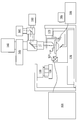
도 1a는 본 명세서에서 개시되는 시스템들 및 방법들이 구현될 수도 있는 예시적인 이미지 스캐닝 시스템의 일반화된 블록도를 도시한다.
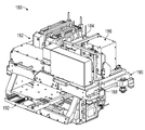
도 1b는 본 명세서에서 개시되는 구현예들에 따라서 예시적인 모듈식 광학 분석 시스템을 도시하는 사시도이다.
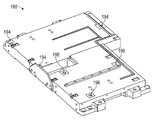
도 1c는 본 명세서에서 개시되는 구현예들에 따라서 예시적인 정밀 장착 플레이트를 도시하는 사시도이다.
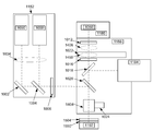
도 1d는 본 명세서에서 개시되는 구현예들에 일치하는 예시적인 모듈식 광학 분석 시스템의 블록도를 도시한다.
도 1e는 본 명세서에서 개시되는 구현예들에 일치하는 예시적인 모듈식 광학 분석 시스템의 사시도를 도시한다.
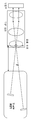
도 1f는 본 명세서에서 개시되는 구현예들에 일치하는 라인 생성 모듈(LGM) 정렬 시스템의 블록도를 도시한다.
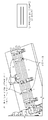
도 1g는 본 명세서에서 개시되는 구현예들에 일치하는 LGM 정렬 시스템의 사시도를 예시한다.
도 1h는 본 명세서에서 개시되는 구현예들에 일치하는 예시적인 모듈식 광학 분석 시스템의 평면도를 도시한다.
도 1i는 본 명세서에서 개시되는 구현예들에 일치하는 예시적인 모듈식 광학 분석 시스템의 측면도를 도시한다.
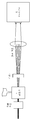
도 1j는 본 명세서에서 개시되는 구현예들에 일치하는 LGM, 대물렌즈, 및 흐름셀의 블록도를 예시한다.
도 1k는 본 명세서에서 개시되는 구현예들에 일치하는 광-포화 및 광퇴색을 피하기 위해 흐름셀 상에 레이저 라인 패턴을 디포커싱하는데 사용되는 LGM 및 EOM 시스템의 블록도를 예시한다.
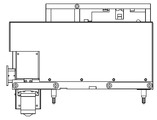
도 2a는 본 명세서에서 개시되는 구현예들에 따라서 방출 광학 모듈(EOM)을 예시하는 측면도이다.
도 2b는 본 명세서에서 개시되는 구현예들에 따라서 EOM을 예시하는 평면도이다.
도 3a는 본 명세서에서 개시되는 구현예들에 따라서 초점 추적 모듈(FTM)을 예시하는 배면도이다.
도 3b는 본 명세서에서 개시되는 구현예들에 따라서 FTM을 예시하는 측면도이다.
도 3c는 본 명세서에서 개시되는 구현예들에 따라서 FTM을 예시하는 평면도이다.
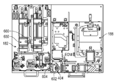
도 4a는 본 명세서에서 개시되는 구현예들에 따라서 예시적인 모듈식 광학 분석 시스템을 도시하는 측면도이다.
도 4b는 본 명세서에서 개시되는 구현예들에 따라서 EOM으로부터 튜브 렌즈 서브어셈블리를 위한 예시적인 구성을 도시하는 블록도이다.
도 4c는 본 명세서에서 개시되는 구현예들에 따라서 EOM으로부터 튜브 렌즈 서브어셈블리를 위한 다른 예시적인 구성을 도시하는 블록도이다.
도 5a는 본 명세서에서 개시되는 구현예들에 따라서 FTM 및 EOM을 예시하는 측면도이다.
도 5b는 본 명세서에서 개시되는 구현예들에 따라서 예시적인 FTM 및 EOM을 예시하는 평면도이다.
도 6은 본 명세서에서 개시되는 구현예들에 따라서 라인 생성 모듈(LGM) 및 EOM을 예시하는 측면도이다.
도 7은 본 명세서에서 개시되는 구현예들에 따라서 LGM 및 EOM을 예시하는 평면도이다.
도 8은 본 명세서에서 개시되는 구현예들에 따라서 모듈식 광학 분석 시스템을 설치하고 구성하기 위한 예시적인 프로세스를 도시하는 도면이다.
도 9는 개시되는 기술의 구현예들의 다양한 특징들을 구현함에 있어서 사용될 수도 있는 예시적인 컴퓨팅 엔진을 도시한다.
개시된 기술이 수정 및 개조로 실시될 수 있다는 것과, 개시된 기술은 청구항들 및 그 동등물들에 의해서만 제한된다는 것이 이해되어야 한다.The techniques disclosed herein in accordance with one or more embodiments are described in detail with reference to the following drawings. These drawings are provided to facilitate the reader's understanding of the disclosed technology, and are not intended to be exhaustive or to limit the disclosure to the precise forms disclosed. Indeed, the Figures in the Figures are provided for illustrative purposes only, and merely illustrate exemplary or exemplary implementations of the disclosed technology. Moreover, for clarity and convenience of illustration, it should be noted that the elements in the figures are not necessarily drawn to scale.
1A shows a generalized block diagram of an exemplary image scanning system in which the systems and methods disclosed herein may be implemented.
1B is a perspective view illustrating an exemplary modular optical analysis system in accordance with embodiments disclosed herein.
Figure 1C is a perspective view illustrating an exemplary precision mounting plate in accordance with the embodiments disclosed herein.
FIG. 1D shows a block diagram of an exemplary modular optical analysis system consistent with the implementations disclosed herein.
Figure IE illustrates a perspective view of an exemplary modular optical analysis system consistent with the implementations disclosed herein.
1F shows a block diagram of a line generation module (LGM) alignment system consistent with the implementations disclosed herein.
FIG. 1G illustrates a perspective view of an LGM alignment system consistent with the implementations disclosed herein.
Figure 1h shows a top view of an exemplary modular optical analysis system consistent with the implementations disclosed herein.
FIG. 1I shows a side view of an exemplary modular optical analysis system consistent with the implementations disclosed herein.
Figure 1J illustrates a block diagram of an LGM, an objective lens, and a flow cell in accordance with embodiments disclosed herein.
Figure 1K illustrates a block diagram of an LGM and EOM system used to defocus a laser line pattern on a flow cell to avoid photo-saturation and light discoloration consistent with the implementations disclosed herein.
2A is a side view illustrating an emission optical module (EOM) according to embodiments disclosed herein.
2B is a top view illustrating EOM in accordance with embodiments disclosed herein.
3A is a rear view illustrating a focus tracking module (FTM) in accordance with the implementations disclosed herein.
3B is a side view illustrating the FTM in accordance with the implementations disclosed herein.
3C is a top view illustrating the FTM in accordance with the implementations disclosed herein.
4A is a side view illustrating an exemplary modular optical analysis system in accordance with the implementations disclosed herein.
4B is a block diagram illustrating an exemplary configuration for a tube lens subassembly from an EOM in accordance with the implementations disclosed herein.
4C is a block diagram illustrating another exemplary configuration for a tube lens subassembly from an EOM in accordance with the implementations disclosed herein.
5A is a side view illustrating FTM and EOM in accordance with embodiments disclosed herein.
Figure 5B is a top view illustrating an exemplary FTM and EOM in accordance with the implementations disclosed herein.
Figure 6 is a side view illustrating a line creation module (LGM) and an EOM in accordance with the implementations disclosed herein.
Figure 7 is a top view illustrating LGM and EOM in accordance with embodiments disclosed herein.
8 is a diagram illustrating an exemplary process for installing and configuring a modular optical analysis system in accordance with the implementations disclosed herein.
Figure 9 illustrates an exemplary computing engine that may be used in implementing various aspects of implementations of the disclosed technology.
It is to be understood that the disclosed technique can be practiced with modification and adaptation, and that the disclosed technique is limited only by the claims and their equivalents.
본 명세서에서 사용되는 바와 같이, "xy 평면"이란 용어는 (데카르트 좌표 시스템에 따른) 일직선 축들(x 및 y)에 의해 정의되는 2 차원 영역을 의미하는 것으로 의도된다. 검출기와 그 검출기에 의해 관찰되는 대상에 관하여 사용될 때, 영역은 검출기와 검출되고 있는 대상 사이의 관찰 방향에 직교하는 것으로서 추가로 특정될 수 있다. 라인 스캐너를 언급하기 위해 본 명세서에서 사용될 때, "y 방향"이란 용어는 스캐닝하는 방향을 지칭한다.As used herein, the term "xy plane" is intended to mean a two-dimensional region defined by straight axes (x and y) (according to the Cartesian coordinate system). When used with respect to the object to be observed by the detector and its detector, the region may be further specified as being orthogonal to the viewing direction between the detector and the object being detected. When used herein to refer to a line scanner, the term "y-direction" refers to the direction of scanning.
본 명세서에서 사용되는 바와 같이, "z 방향" 또는 "z 축"이란 용어는 검출기에 의해 관찰되는 대상의 영역에 직교하는 방향 또는 축을 특정하기 위해 의도된다. 예를 들어, 광학 시스템에 대한 초점의 방향은 z 축을 따라 특정될 수도 있다.As used herein, the term "z-direction" or "z-axis" is intended to specify a direction or axis orthogonal to the area of the object being observed by the detector. For example, the direction of focus to the optical system may be specified along the z-axis.
본 명세서에서 개시되는 일부 구현예들은 모듈식 광학 시스템, 이를테면 생물학적 샘플들을 분석하는데 사용될 수도 있는 것들을 제공한다. 본 명세서에서 개시되는 다른 구현예들은 생물학적 샘플들을 분석하기 위한 모듈식 광학 시스템들을 조립 및 설치하는 방법들을 제공한다. 하나의 이러한 광학 시스템은 게놈 시퀀싱 기구일 수도 있거나, 또는 그러한 기구의 일부일 수도 있다. 그 기구는 시퀀스 DNA, RNA, 또는 다른 생물학적 샘플들을 시퀀스화하는데 사용될 수도 있다. 일부 게놈 시퀀싱 기구들은 상이한 파장들에서 동작하는 간섭성 또는 비간섭성 광원들을 내부 광학계를 통해 그리고 샘플 상으로 포커싱함으로써 동작한다. 샘플에 존재하는 염기쌍들은 그러면 형광을 발하고 광을 시퀀서의 광학계를 통해 그리고 광 센서 상으로 반환하고, 그러면 광 센서는 존재하는 염기쌍들의 유형들을 검출할 수 있다. 이들 유형들의 기구들은 내부 광학계의 정밀한 정렬 및 튜닝에 의존하고, 열 효과에 의해 (예컨대, 광원들 및 전자기기로부터의 가열에 의해) 야기된 컴포넌트들의 드리프팅 또는 오정렬, 뿐만 아니라 진동들과 같은 기계적 효과 또는 사용자들부터의 부수적인 접촉에 민감하다. 본 개시물의 구현예들은 이들 문제들과, 그것들에 연관된 설치 및 유지보수 비용들을, 모듈식 접근법을 통해 해결한다. 기능적으로 관련된 광학 컴포넌트들의 그루핑들은 모듈식 서브어셈블리들로서 미리 패키징되며, 테스트되고, 정렬될 수도 있다. 각각의 모듈식 서브어셈블리는 그러면 서브어셈블리를 정밀 정렬 플레이트 상에 장착함으로써 시스템에 설치되고 다른 모듈식 서브어셈블리들에 정렬될 수도 있는 현장 교체가능 유닛(field replaceable unit, FRU)으로서 취급될 수도 있다.Some embodiments disclosed herein provide modular optical systems, such as those that may be used to analyze biological samples. Other implementations disclosed herein provide methods for assembling and installing modular optical systems for analyzing biological samples. One such optical system may be a genome sequencing mechanism, or it may be part of such an apparatus. The instrument may be used to sequence the sequence DNA, RNA, or other biological samples. Some genome sequencing tools operate by focusing coherent or non-coherent light sources operating at different wavelengths through an internal optical system and onto a sample. The base pairs present in the sample then fluoresce and return the light through the optical system of the sequencer and onto the photosensor, which can then detect the types of base pairs present. These types of mechanisms rely on precise alignment and tuning of the internal optical system and are dependent on the mechanical properties such as drift or misalignment of components caused by thermal effects (e.g., by heating from light sources and electronics) Effect or ancillary contacts from users. Implementations of the present disclosure solve these problems and their associated installation and maintenance costs through a modular approach. The groupings of functionally related optical components may be pre-packaged, tested, and ordered as modular subassemblies. Each modular subassembly may then be treated as a field replaceable unit (FRU) that is installed in the system by mounting the subassembly on the precision alignment plate and may be aligned with other modular subassemblies.
개시물의 일부 구현예들은 복수의 모듈식 서브어셈블리들과 정밀 장착 플레이트를 포함하는 시스템을 제공하는데, 각각의 모듈식 서브어셈블리는 인클로저와 인클로저에 정렬된 복수의 광학 컴포넌트들을 포함한다. 인클로저는 복수의 정밀 장착 구조들을 포함할 수도 있고, 각각의 모듈식 서브어셈블리는 정밀 장착 플레이트에 기계적으로 커플링될 수도 있어서, 모듈식 서브어셈블리로부터의 각각의 정밀 장착 구조는 정밀 장착 플레이트 또는 인접한 모듈식 서브어셈블리 상에 위치된 대응하는 정밀 장착 구조에 직접적으로 결부된다. 일부 예들에서, 라인 생성 모듈은 제 1 파장에서 동작하는 제 1 광원, 제 2 파장에서 동작하는 제 2 광원, 및 각각의 광원에 대해 미리 결정된 각도로 정렬되는 빔 성형 렌즈를 포함한다. 예를 들어, 제 1 파장은 녹색 파장일 수도 있고 제 2 파장은 적색 파장일 수도 있다. 빔 성형 렌즈는 파월 렌즈일 수도 있다.Some embodiments of the disclosure provide a system comprising a plurality of modular subassemblies and a precision mounting plate, wherein each modular subassembly includes a plurality of optical components arranged in an enclosure and an enclosure. The enclosure may include a plurality of precision mounting structures and each modular subassembly may be mechanically coupled to the precision mounting plate so that each precision mounting structure from the modular subassembly may be coupled to the precision mounting plate or adjacent module And is directly coupled to a corresponding precision mounting structure located on the expression subassembly. In some examples, the line generation module includes a first light source that operates at a first wavelength, a second light source that operates at a second wavelength, and a beam shaping lens that is aligned at a predetermined angle for each light source. For example, the first wavelength may be a green wavelength and the second wavelength may be a red wavelength. The beam shaping lens may be a powell lens.
일부 구현예들에서, 방출 광학계 모듈은 광 생성 모듈에 광학적으로 커플링되는 대물렌즈와, 대물렌즈에 광학적으로 커플링되는 튜브 렌즈를 포함할 수도 있다. 대물렌즈는 흐름셀로부터 미리 결정된 거리에 위치된 흐름셀 상에 광을 포커싱한다. 대물렌즈는 경도 축을 따라 교합할 수도 있고, 튜브 렌즈는 정확한 이미징을 확실히 하기 위해 튜브 렌즈 내에서 경도 축을 따라 또한 교합하는 렌즈 컴포넌트를 포함할 수도 있다. 예를 들어, 렌즈 컴포넌트는 흐름셀의 하나 또는 그 초과의 표면들을 이미지화하기 위한 대물렌즈의 교합에 의해 야기된 구면수차를 보상하기 위해 이동할 수도 있다.In some embodiments, the emission optical module may include an objective lens optically coupled to the light generating module and a tube lens optically coupled to the objective lens. The objective lens focuses the light onto the flow cell located a predetermined distance from the flow cell. The objective lens may be occluded along the longitudinal axis, and the tube lens may include a lens component that also occludes along the longitudinal axis within the tube lens to ensure correct imaging. For example, the lens component may move to compensate for spherical aberration caused by occlusion of the objective lens to image one or more surfaces of the flow cell.
일부 예들에서, 흐름셀은 반투명 덮개 판, 기판, 및 그것들 사이에 끼어 있는 액체를 포함할 수도 있고, 생물학적 샘플이 반투명 덮개 판의 내부 표면 또는 기판의 내부 표면에 위치될 수도 있다. 예를 들어, 생물학적 샘플은 시퀀스화될 수도 있는 DNA, RNA, 또는 다른 게놈 재료를 포함할 수도 있다.In some instances, the flow cell may include a translucent cover plate, a substrate, and liquid interspersed therewith, and the biological sample may be located on the inner surface of the translucent cover plate or the inner surface of the substrate. For example, the biological sample may comprise DNA, RNA, or other genomic material that may be sequenced.
초점 추적 모듈은 초점 추적 광원과 초점 추적 센서를 포함할 수도 있는데, 그 광원은 광 빔을 생성하며, 그 광 빔을 광 빔이 초점 추적 센서에서 종단하도록 복수의 광학 컴포넌트들을 통해 전달할 수도 있다. 초점 추적 센서는 프로세서와 머신 판독가능 명령들을 저장하고 있는 비-일시적 컴퓨터 판독가능 매체에 통신적으로 커플링될 수도 있다. 머신 판독가능 명령들은, 실행될 때, 프로세서로 하여금, 초점 추적 센서로부터의 출력 신호를 수신하고 그 출력 신호를 분석하여 광 빔의 특성들의 세트를 결정하게 할 수도 있다. 일부 예들에서, 머신 판독가능 명령들은 추가로, 실행될 때, 프로세서로 하여금, 광학 컴포넌트들 중 하나 또는 그 초과의 광학 컴포넌트가 광 빔의 특성들의 세트를 최적화하도록 재구성되어야 함을 나타내는 피드백 신호를 생성하게 한다. 모듈식 서브어셈블리들 중 하나 또는 그 초과의 모듈식 서브어셈블리는 현장 교체가능 유닛일 수도 있다. 정밀 장착 구조들은 슬롯, 데이텀, 탭, 핀, 또는 오목한 공동, 본 기술분야에서 공지된 바와 같은 다른 기계적 장착 구조들, 또는 그것들의 임의의 조합을 포함할 수도 있다.The focus tracking module may include a focus tracking light source and a focus tracking sensor that generates a light beam and may transmit the light beam through the plurality of optical components such that the light beam terminates in a focus tracking sensor. The focus tracking sensor may be communicatively coupled to the processor and to a non-transitory computer readable medium storing machine readable instructions. The machine readable instructions, when executed, may cause the processor to receive an output signal from the focus tracking sensor and analyze the output signal to determine a set of characteristics of the light beam. In some instances, the machine-readable instructions further cause, when executed, to cause the processor to generate a feedback signal indicating that one or more of the optical components should be reconfigured to optimize the set of properties of the light beam do. One or more of the modular subassemblies may be field replaceable units. The precise mounting structures may include slots, datum, tabs, pins, or recessed cavities, other mechanical mounting structures as known in the art, or any combination thereof.
일부 예들에서, 카메라 모듈은 복수의 광 센서들을 포함하고, 광 생성 모듈은 복수의 광원들을 포함하는데, 각각의 광 센서는 광 빔을 대응하는 광원으로부터 수신하고 검출하도록 배향될 수도 있다.In some examples, the camera module includes a plurality of optical sensors, and the light generating module includes a plurality of light sources, each of which may be oriented to receive and detect a light beam from a corresponding light source.
본원에서 개시된 시스템들 및 방법들의 다양한 구현예들을 설명하기 전에, 시스템들 및 방법들이 구현될 수도 있는 예시적인 환경을 설명하는 것이 유용하다. 하나의 이러한 예시적인 환경은 도 1a에 예시된 바와 같은 광학 시스템의 환경이다. 예시적인 광학 시스템은 지역의 이미지를 획득하거나 또는 생산하기 위한 디바이스를 포함할 수도 있다. 도 1에서 약술되는 예는 백라이트 설계 구현예의 예시적인 이미징 구성을 도시한다.Before describing various implementations of the systems and methods disclosed herein, it is useful to describe an exemplary environment in which systems and methods may be implemented. One such exemplary environment is the environment of the optical system as illustrated in FIG. 1A. An exemplary optical system may include a device for acquiring or producing an image of a region. The example outlined in Figure 1 illustrates an exemplary imaging configuration of a backlight design implementation.
도 1a의 예에서 알 수 있는 바와 같이, 대상 샘플들은 대물렌즈(142) 하의 샘플 스테이지(170) 상에 위치되는 샘플 구조체 또는 컨테이너(110)(예컨대, 본 명세서에서 개시되는 바와 같은 흐름셀) 상에 위치된다. 광원(160) 및 연관된 광학계는 광, 이를테면 레이저 광의 빔을 샘플 컨테이너(110) 상의 선택된 샘플 로케이션으로 진행시킨다. 그 샘플을 형광을 발하고 결과적인 광은 대물렌즈(142)에 의해 수집되고 형광을 검출하기 위해 광 검출기(140)로 진행된다. 샘플 스테이지(170)는 대물렌즈(142)의 초점에 있는 샘플 컨테이너(110) 상의 다음 샘플 로케이션에 위치하도록 대물렌즈(142)를 기준으로 이동된다. 대물렌즈(142)를 기준으로 하는 샘플 스테이지(110)의 이동은 샘플 스테이지 자체, 대물렌즈, 전체 광학 스테이지, 또는 전술한 바의 임의의 조합을 이동시킴으로써 성취될 수 있다. 추가의 구현예들은 정지 샘플 위에서 전체 이미징 시스템을 이동시키는 것을 또한 포함할 수도 있다.As can be seen in the example of Figure 1A, the sample of interest is a sample structure or container 110 (e.g., a flow cell as disclosed herein) positioned on a
유체 전달 모듈 또는 디바이스(100)는 시약들(예컨대, 형광 뉴클레오티드, 완충제, 효소, 분열(cleavage) 시약들 등)의 흐름을 샘플 컨테이너(110) 및 폐기 밸브(120)로 (그리고 그것들을 통해) 진행시킨다. 특정 구현예들에서, 샘플 컨테이너(110)는 샘플 컨테이너(110) 상의 복수의 샘플 로케이션들에서 핵산 서열들의 클러스터들을 포함하는 흐름셀로서 구현될 수 있다. 시퀀스화될 샘플들은 다른 옵션적인 컴포넌트들과 함께, 흐름셀의 기판에 부착될 수도 있다.A fluid delivery module or
시스템은 샘플 컨테이너(110) 내의 유체들의 환경의 온도를 옵션적으로 조절할 수 있는 온도 스테이션 액추에이터(130) 및 가열기/냉각기(135)를 또한 포함한다. 카메라 시스템(140)은 샘플 컨테이너(110)의 시퀀싱을 모니터링 및 추적하기 위해 포함될 수 있다. 카메라 시스템(140)은, 예를 들어, 필터 스위칭 어셈블리(145) 내의 다양한 필터들, 대물렌즈(142), 및 포커싱 레이저/포커싱 레이저 어셈블리(150)와 상호작용할 수 있는 CCD 카메라로서 구현될 수 있다. 카메라 시스템(140)은 CCD 카메라로 제한되지 않고 다른 카메라들 및 이미지 센서 기술들이 사용될 수 있다.The system also includes a
광원(160)(예컨대, 어셈블리 내의 여기 레이저는 다수의 레이저들을 옵션적으로 포함함) 또는 다른 광원이 광섬유 인터페이스(161)(이는 하나 또는 그 초과의 재-결상 렌즈들, 광섬유 마운팅 등을 옵션적으로 포함할 수 있음)를 통하는 조명을 통해 샘플들 내의 형광 시퀀싱 반응들에 조명하기 위해 포함될 수 있다. 낮은 와트 램프(165), 포커싱 레이저(150), 및 역 이색거울(reverse dichroic)(185)이 도시된 예에서 또한 제시된다. 일부 구현예들에서 포커싱 레이저(150)는 이미징 동안 턴 오프될 수도 있다. 다른 구현들에서, 대안적 초점 구성이 제 2 포커싱 카메라(도시되지 않음)를 포함할 수 있는데, 이 제 2 포커싱 카메라는 데이터 수집과 동시에 발생하는 표면으로부터 반사된 산란된 빔의 로케이션을 측정하기 위한 사분면(quadrant) 검출기, 포지션 감응 검출기(PSD), 또는 유사한 검출기일 수 있다.The light source 160 (e.g., an excitation laser in the assembly optionally includes a plurality of lasers) or other light source may be coupled to the fiber optic interface 161 (which may include one or more re-imaging lenses, fiber- To illuminate the fluorescence sequencing reactions in the samples through the illumination through the sample. A
비록 백릿 디바이스로서 예시되지만, 다른 예들이 대물렌즈(142)를 통해 샘플 컨테이너(110) 상의 샘플들 상으로 진행되는 레이저 또는 다른 광원으로부터의 광을 포함할 수도 있다. 샘플 컨테이너(110)는 대물렌즈(142)를 기준으로 샘플 컨테이너(110)의 이동 및 정렬을 제공하기 위해 샘플 스테이지(170) 상에 궁극적으로 장착될 수도 있다. 샘플 스테이지는 자신이 세 개의 차원들 중 임의의 차원에서 이동하는 것을 허용하는 하나 또는 그 초과의 액추에이터들을 가질 수 있다. 예를 들어, 데카르트 좌표 시스템의 측면에서, 액추에이터들은 스테이지가 대물렌즈를 기준으로 X, Y 및 Z 방향들에서 이동하는 것을 허용하도록 제공될 수 있다. 이는 샘플 컨테이너(110) 상의 하나 또는 그 초과의 샘플 로케이션들이 대물렌즈(142)와 광학적 정렬로 위치되는 것을 허용할 수 있다.Although illustrated as a backlit device, other examples may include light from a laser or other light source that travels through the objective lens 142 onto the samples on the
초점(z-축) 컴포넌트(175)가 이 예에서 초점 방향(통상 z 축, 또는 z 방향이라고 지칭됨)에서 샘플 컨테이너(110)를 기준으로 광학 컴포넌트들의 포지셔닝을 제어하기 위해 포함되어 있는 것으로서 도시된다. 초점 컴포넌트(175)는 광학 컴포넌트들(예컨대, 대물렌즈(142))을 기준으로 샘플 스테이지(170) 상에서 샘플 컨테이너(110)를 이동시켜 이미징 동작을 위한 적절한 포커싱을 제공하기 위해, 광학 스테이지 또는 샘플 스테이지, 또는 둘 다에 물리적으로 커플링되는 하나 또는 그 초과의 액추에이터들을 포함할 수 있다. 예를 들어, 액추에이터는, 예를 들어, 스테이지에 또는 스테이지와는 직접적으로 또는 간접적으로 기계적, 자기적, 유체적 또는 다른 부착 또는 접촉에 의해 각각의 스테이지에 물리적으로 커플링될 수도 있다. 하나 또는 그 초과의 액추에이터들은 스테이지를 z-방향에서 이동시키면서 동시에 샘플 스테이지를 동일한 평면에서 유지(예컨대, 광축에 수직인 레벨 또는 수평 자세를 유지)시키도록 구성될 수 있다. 하나 또는 그 초과의 액추에이터들은 스테이지를 틸팅하도록 또한 구성될 수 있다. 이는, 예를 들어, 샘플 컨테이너(110)가 자신의 표면들에서의 임의의 기울기를 고려하기 위해 동적으로 수평화(leveling)될 수 있도록 행해질 수 있다.A focus (z-axis)
시스템의 포커싱은 선택된 샘플 로케이션에서 이미지화될 샘플과 대물렌즈의 초점면을 정렬하는 것을 일반적으로 지칭한다. 그러나, 포커싱은 예를 들어, 테스트 샘플의 이미지에 대한 선명도 또는 콘트라스트의 원하는 레벨과 같은 샘플의 표현을 위한 원하는 특성을 획득하기 위한 시스템에 대한 조정들을 또한 지칭할 수 있다. 대물렌즈의 초점면의 사용가능 필드 깊이가 (때때로 1 ㎛ 이하 정도로) 작을 수도 있기 때문에, 초점 컴포넌트(175)는 이미지화되고 있는 표면을 긴밀하게 추종한다. 샘플 컨테이너가 기구에 고정된 것으로서 완전히 평평하지 않기 때문에, 초점 컴포넌트(175)는 스캐닝 방향(본 명세서에서 y-축이라고 지칭됨)에서 이동하는 동안 이 프로파일을 추종하도록 설정될 수도 있다.Focusing of the system generally refers to aligning the focal plane of the objective with the sample to be imaged at the selected sample location. Focusing, however, may also refer to adjustments to the system to obtain the desired characteristics for the representation of the sample, for example, the sharpness of the image of the test sample or the desired level of contrast. Because the available field depth of the objective lens's focal plane may be small (on the order of 1 micrometer or less), the
이미지화되고 있는 샘플 로케이션에서 테스트 샘플로부터 나오는 광은 하나 또는 그 초과의 검출기들(140)로 진행될 수 있다. 검출기들은, 예를 들어 CCD 카메라를 포함할 수 있다. 개구부가 초점 영역으로부터 나오는 광만을 검출기로 전달하는 것을 허용하도록 포함되고 포지셔닝될 수 있다. 개구부는 초점 영역의 외부에 있는 영역들로부터 나오는 광의 성분들을 필터링함으로써 이미지 품질을 개선하기 위해 포함될 수 있다. 방출 필터들은 필터 스위칭 어셈블리(145)에 포함될 수 있는데, 그러한 방출 필터들은 결정된 방출 파장을 기록하고 임의의 엇나간(stray) 레이저 광을 차단하도록 선택될 수 있다.The light from the test sample in the sample location being imaged may proceed to one or
다양한 구현예들에서, 샘플 컨테이너(110)는 샘플들이 위에 제공되는 하나 또는 그 초과의 기판들을 포함할 수 있다. 예를 들어, 다수의 상이한 핵산 서열들을 분석하는 시스템의 경우, 샘플 컨테이너(110)는 서열화될 핵산들이 본딩, 부착 또는 연관될 하나 또는 그 초과의 기판들을 포함할 수 있다. 다양한 구현예들에서, 기판은, 예를 들어 유리 표면들, 플라스틱 표면들, 라텍스, 덱스트란, 폴리스티렌 표면들, 폴리프로필렌 표면들, 폴리아크릴아미드 젤들, 금 표면들, 및 실리콘 웨이퍼들과 같이, 핵산들이 부착될 수 있는 임의의 불활성 기판 또는 매트릭스를 포함할 수 있다. 일부 애플리케이션들에서, 기판은 샘플 컨테이너(110) 전체에 걸쳐 매트릭스 또는 어레이로 형성되는 복수의 로케이션들에서의 채널 또는 다른 영역 내에 있다.In various implementations, the
비록 예시되지 않았지만, 제어기가 스캐닝 시스템의 동작을 제어하기 위해 제공될 수 있다. 제어기는, 예를 들어, 포커싱, 스테이지 이동, 및 이미징 동작들과 같은 시스템 동작의 양태들을 제어하도록 구현될 수 있다. 다양한 구현예들에서, 제어기는 하드웨어, 알고리즘들(예컨대, 머신 실행가능 명령들), 또는 전술한 바의 조합을 사용하여 구현될 수 있다. 예를 들어, 일부 구현예들에서 제어기는 하나 또는 그 초과의 CPU들 또는 프로세서들을 연관된 메모리와 함께 포함할 수 있다. 다른 예로서, 제어기는 동작을 제어하는 하드웨어 또는 다른 회로부, 이를테면 컴퓨터 프로세서와 머신 판독가능 명령들을 저장하고 있는 비-일시적 컴퓨터 판독가능 매체를 포함할 수 있다. 예를 들어, 이 회로부는, 현장 프로그램가능 게이트 어레이(field programmable gate array, FPGA), 주문형 집적회로(application specific integrated circuit, ASIC), 프로그램가능 로직 디바이스(programmable logic device, PLD), 복합 프로그램가능 로직 디바이스(complex programmable logic device, CPLD), 프로그램가능 로직 어레이(programmable logic array, PLA), 프로그램가능 어레이 로직(programmable array logic, PAL) 또는 다른 유사한 프로세싱 디바이스 또는 회로부 중 하나 또는 그 초과를 포함할 수 있다. 또 다른 예로서, 제어기는 이 회로부와 하나 또는 그 초과의 프로세서들의 조합을 포함할 수 있다.Although not illustrated, a controller may be provided for controlling the operation of the scanning system. The controller may be implemented to control aspects of system operation, such as, for example, focusing, stage movement, and imaging operations. In various implementations, the controller may be implemented using hardware, algorithms (e.g., machine executable instructions), or a combination of the foregoing. For example, in some implementations the controller may include one or more CPUs or processors with associated memory. As another example, the controller may include hardware or other circuitry to control operation, such as non-transient computer readable media storing computer processors and machine-readable instructions. For example, the circuitry may be a field programmable gate array (FPGA), an application specific integrated circuit (ASIC), a programmable logic device (PLD) And may include one or more of a complex programmable logic device (CPLD), a programmable logic array (PLA), programmable array logic (PAL), or other similar processing device or circuitry . As another example, the controller may include this circuitry and a combination of one or more processors.
비록 시스템들 및 방법들이 때때로 이 예시적인 시스템의 맥락에서 본 명세서에서 설명될 수도 있지만, 이는 이들 시스템들 및 방법들이 구현될 수도 있는 단지 하나의 예이다. 이 설명을 읽은 후, 본 기술분야의 통상의 기술자는 본 명세서에서 설명되는 시스템들 및 방법들이 이런 및 다른 스캐너들, 현미경들 및 다른 이미징 시스템들로 구현될 수 있는 방법을 이해할 것이다.Although systems and methods may sometimes be described herein in the context of this exemplary system, this is just one example in which these systems and methods may be implemented. After reading this description, one of ordinary skill in the art will understand how the systems and methods described herein may be implemented with these and other scanners, microscopes, and other imaging systems.
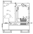
본 명세서에서 개시된 기술의 구현예들은 모듈식 광학 분석 시스템들 및 방법들을 제공한다. 도 1b는 예시적인 모듈식 광학 분석 시스템(180)을 도시하는 사시도이다. 시스템(180)은 복수의 모듈식 서브어셈블리들을 포함할 수도 있다. 예를 들어, 일부 구현예들에서, 시스템(180)은 네 개의 서브어셈블리 모듈들, 즉, 라인 생성 모듈(LGM)(182), 초점 추적 모듈(FTM)(184), 카메라 모듈(CAM)(186), 및 방출 광학 모듈(EOM)(188)을 포함한다. LGM, FTM, EOM, 또는 CAM의 맥락에서 본원에서 사용되는 바와 같이, 모듈이 하드웨어 유닛(예컨대, 모듈식 서브어셈블리)을 지칭한다.Implementations of the techniques disclosed herein provide modular optical analysis systems and methods. FIG. 1B is a perspective view illustrating an exemplary modular
일부 구현예들에서, LGM(182)은 하나 또는 그 초과의 광원들을 포함할 수도 있다. 일부 구현예들에서, 하나 또는 그 초과의 광원들은 간섭성 광원들, 이를테면 레이저 다이오드들을 포함할 수도 있다. 일부 예들에서, LGM(182)은 적색 파장들의 광을 방출하도록 구성되는 제 1 광원과, 녹색 파장들의 광을 방출하도록 구성되는 제 2 광원을 포함할 수도 있다. LGM(182)은 광학 컴포넌트들, 이를테면 포커싱 표면들, 렌즈들, 반사성 표면들, 또는 거울들을 추가로 포함할 수도 있다. 광학 컴포넌트들은 하나 또는 그 초과의 광원들로부터 방출된 광을 인접한 모듈식 서브어셈블리로 진행시키고 포커싱하기 위해 LGM(182)의 인클로저 내부에 위치될 수도 있다. LGM(182)의 광학 컴포넌트들 중 하나 또는 그 초과의 광학 컴포넌트는 하나 또는 그 초과의 광원들로부터 방출된 광을 원하는 패턴들로 성형하도록 또한 구성될 수도 있다. 예를 들어, 일부 구현예들에서, 광학 컴포넌트들은 (예컨대, 하나 또는 그 초과의 파월 렌즈들, 또는 다른 빔 성형 렌즈들, 회절 또는 산란 컴포넌트들을 사용함으로써) 광을 라인 패턴들로 성형할 수도 있다. 광학 컴포넌트들 중 하나 또는 그 초과의 광학 컴포넌트가 다른 모듈식 서브어셈블리들 중 하나 또는 그 초과의 모듈식 서브어셈블리에 위치될 수도 있다. 모듈식 서브어셈블리들 중 하나 또는 그 초과의 모듈식 서브어셈블리는 하나 또는 그 초과의 필드 대체가능 서브-컴포넌트들을 또한 포함할 수도 있다. 예를 들어, LGM(182)은 LGM(182)으로부터 개별적으로 제거되고 대체될 수도 있는 하나 또는 그 초과의 레이저 모듈들을 포함할 수도 있다.In some implementations, the
일부 예들에서, 인접한 모듈식 서브어셈블리(LGM(182)에 커플링됨)는 EOM(188)일 수도 있다. LGM(182)의 하나 또는 그 초과의 광원들로부터의 광은 LGM(182) 및/또는 EOM(188)에 부착된 인터페이스 배플을 통해 LGM(182) 밖으로 그리고 EOM(188) 속으로 진행될 수도 있다. 예를 들어, 인터페이스 배플은 외부 광원들로부터의 간섭을 차폐(obscuring)하면서 광이 자신의 중앙을 통과하는 것을 가능하게 하도록 성형된 개구부일 수도 있다. EOM(188)은 LGM(182)의 하나 또는 그 초과의 광원들에 의해 여기된 형광 광을 성형, 진행 및/또는 포커싱하도록 구성되는 대물렌즈, 튜브 렌즈, 및 또는 다른 광학 컴포넌트들을 또한 포함할 수도 있다.In some instances, an adjacent modular subassembly (coupled to LGM 182) may be an
EOM(188)을 통과하는 광은 인터페이스 포트를 통해 다른 인접한 모듈식 서브어셈블리들 중 하나, 예를 들어, CAM(186) 속으로 진행될 수도 있다. CAM(188)은 하나 또는 그 초과의 광 센서들을 포함할 수도 있다. 일부 구현예들에서, 제 1 광 센서가 LGM(182)의 제 1 광원으로부터의 광을 (예컨대, 적색 파장에서) 검출하도록 구성될 수도 있고, 제 2 광 센서가 LGM(182)의 제 2 광원으로부터의 광(예컨대, 녹색 파장)을 검출하도록 구성될 수도 있다. CAM(186)의 광 센서들은 두 개의 입사 광 빔들 - 그 입사 광 빔들은 두 개의 센서들의 피치에 기초하여 미리 결정된 거리(예컨대, 1 mm와 10 mm 사이)만큼 이격될 수도 있음 - 로부터 광을 검출하는 것과 같은 구성에서 인클로저 내부에 위치될 수도 있다. 일부 예들에서, 제 1 광 센서와 제 2 광 센서는 3 mm와 8 mm 사이만큼 서로 이격될 수도 있다. 광 센서들은, 예를 들어 열 효과 또는 기계적 크리프(creep)로 인한, 빔 드리프트를 허용하는 충분한 사이즈로 된 검출 표면을 가질 수도 있다. CAM(186)의 광 센서들로부터의 출력 데이터는 컴퓨터 프로세서에 전달될 수도 있다. 컴퓨터 프로세서는 그러면 데이터를 분석하고 빔의 특성들(예컨대, 초점, 형상, 세기, 전력, 밝기, 포지션)을 그래픽 사용자 인터페이스(GUI)에 보고 또는 디스플레이하며, 그리고/또는 레이저 빔을 최적화하기 위해 액추에이터들 및 레이저 출력을 자동으로 제어하도록 컴퓨터 소프트웨어 프로그램 명령들을 구현할 수도 있다. 빔 성형 및 포지션은 시스템(180)의 내부 광학계(예컨대, 틸팅 거울들, 교합 렌즈들 등)를 교합시킴으로써 최적화될 수도 있다.Light passing through the
FTM(184)은 인터페이스 포트를 통해 EOM(188)에 또한 커플링될 수도 있다. FTM(184)은 시스템(180)에서 광학 컴포넌트들의 모두의 정렬 및 초점을 검출하고 분석하는 기구들을 포함할 수도 있다. 예를 들어, FTM(184)은 광원(예컨대, 레이저), 광학계, 및 광 센서, 이를테면 디지털 카메라 또는 CMOS 칩을 포함할 수도 있다. 레이저는 광 소스를 전달하도록 구성될 수도 있고 광학계는 시스템(180)에서의 광학 컴포넌트들을 통해 광을 진행시키도록 구성될 수도 있고 광 센서는 시스템(180)에서의 광학 컴포넌트들을 통해 전달되고 있는 광을 검출하고 데이터를 컴퓨터 프로세서로 출력하도록 구성될 수도 있다. 컴퓨터 프로세서는 그러면 데이터를 분석하고 레이저 빔의 특성들(예컨대, 초점, 세기, 전력, 밝기, 포지션)을 그래픽 사용자 인터페이스(GUI)에 보고 또는 디스플레이하며, 그리고/또는 레이저 빔을 최적화하기 위해 액추에이터들 및 레이저 출력을 자동으로 제어하도록 컴퓨터 소프트웨어 프로그램 명령들을 구현할 수도 있다. 일부 예들에서, FTM(184)은 본 기술분야에서 공지된 바와 같은 에어 또는 액체 냉각 시스템과 같은 냉각 시스템을 포함할 수도 있다.The
일부 구현예들에서, LGM(182)은 더 빠른 스캐닝 속력들을 또한 수용하기 위해 더 높은 전력들에서 동작하는 광원들을 포함할 수도 있다(예컨대, LGM(182)에서의 레이저들은 다섯 배 큰 전력 출력에서 동작할 수도 있다). 마찬가지로, 레이저 모듈(184)의 광원은 더 높은 출력 전력에서 동작할 수도 있고 그리고/또는 더 빠른 스캐닝 속력들을 수용하기 위한 나노미터 스케일 초점 정밀도를 성취하기 위해 고 분해능 광 센서를 또한 포함할 수도 있다. FTM(184)의 냉각 시스템은 본 기술분야에서 공지된 냉각 기법들을 사용하여 더 높은 전력으로 된 레이저로부터 출력되는 추가적인 열을 수용하도록 향상될 수도 있다.In some embodiments, the
하나의 예에서, 각각의 모듈식 서브어셈블리가 하나 또는 그 초과의 다른 모듈식 서브어셈블리들에, 그리고/또는 정밀 장착 플레이트(190)에 기계적으로 커플링될 수도 있다. 일부 구현예들에서, 정밀 장착 플레이트(190)는 스테이지 어셈블리(192)에 기계적으로 커플링될 수도 있다. 스테이지 어셈블리(192)는 모션 댐퍼들, 하나 또는 그 초과의 모듈식 서브어셈블리들 내의 하나 또는 그 초과의 컴포넌트들을 작동시키기 위한 액추에이터들, 냉각 시스템들, 및/또는 본 기술분야에서 공지된 바와 같은 다른 전자 또는 기계 컴포넌트들을 포함할 수도 있다.In one example, each modular subassembly may be mechanically coupled to one or more other modular subassemblies and / or
모듈식 서브어셈블리들은 조립되며, 구성되고, 내부적으로 정렬될 수도 있다. 일부 구현예들에서, 하나 또는 그 초과의 모듈식 서브어셈블리들이 정밀 장착 플레이트(190)에 커플링된 후 그것들의 자동 또는 원격 수동 정렬을 가능하게 하기 위해 제어 유닛이 스테이지 어셈블리(192)에 전자적으로 커플링되고 사용자 인터페이스에 통신적으로 커플링될 수도 있다. 각각의 모듈식 서브어셈블리는 현장 교체가능 유닛(field replaceable unit, FRU)일 수도 있어서, 그것은 시스템에서 다른 모듈식 서브어셈블리들의 정렬 또는 구성을 방해하지 않고 정밀 장착 플레이트(190)로부터 제거되고 다른 기능적으로 동등한 모듈식 서브어셈블리로 대체될 수도 있다.The modular subassemblies may be assembled, configured, and internally aligned. In some embodiments, after one or more modular subassemblies are coupled to the
각각의 모듈은 시스템(180)으로의 통합 전에 미리 정렬되고 미리 규정된다. 예를 들어, LGM(182)의 어셈블리 및 구성은 하나 또는 그 초과의 레이저들 또는 레이저 다이오드들의 인클로저 속으로의 기계적 커플링과, 레이저들 또는 레이저 다이오드들을 동작시키는 제어 전자기기의 설치를 포함할 수도 있다. 전체 LGM(182)은 그러면 테스트 베드 상에 장착되고 인클로저, 뿐만 아니라 임의의 광학계 또는 다른 컴포넌트들 내의 레이저 다이오드들을 정렬시키도록 동작될 수도 있다. LGM 인클로저는 LGM(182)을 테스트 베드에, 뿐만 아니라 시스템(180)에 설치된 때의 정밀 장착 플레이트(190)에 관해 정렬시키도록 구성되는 외부 장착 구조체들, 이를테면 장착 핀들, 데이텀, 노치들, 탭들, 슬롯들, 리지들(ridges), 또는 다른 돌출부들 또는 오목부들을 포함할 수도 있다. 일단 LGM(182)이 구성되고 테스트되면, 그것은 시스템(182)에 설치되거나, 또는 현장 교체가능 유닛(FRU)으로서 패키징되고 보관되거나 또는 출하될 수도 있다.Each module is pre-defined and pre-defined prior to integration into
다른 모듈식 서브어셈블리들, 이를테면 FTM(184), CAM(186), 또는 EOM(188)이, 시스템(180) 상의 설치 전에 유사하게 조립되며, 구성되고, 테스트될 수도 있다. 각각의 모듈식 서브어셈블리는 서브어셈블리 내의 내부 컴포넌트들의 이동도를 원하는 대로 제한하기 위해 기계적 커플링 방법들을 사용하여 조립될 수도 있다. 예를 들어, 컴포넌트가 다른 컴포넌트들 또는 모듈식 서브어셈블리의 인클로저에 정렬되면 이동성을 중지하기 위해 컴포넌트들은 파스너들 또는 용접부들로 제자리에 고정될 수도 있다. 일부 컴포넌트들은, 원하는 대로, 그것들의 상대적인 배향이 정밀 장착 플레이트(190) 상의 설치 후에 조정될 수도 있도록 교합 조인트들과 커플링되거나 또는 인클로저 내에서 이동하는 것이 허용될 수도 있다. 예를 들어, 각각의 모듈식 서브어셈블리의 상대 포지셔닝은 제한된 수의 조정가능 자유도들(예컨대, 일부 구현예들에서 10 미만의 전체 자유도들)로 시스템(180)의 전체 광학 정렬을 가능하게 하기 위한 것과 같은 미리 결정된 기계적 허용오차들을 사용하여 (예컨대, 인접한 모듈식 서브어셈블리에서의 또는 정밀 장착 플레이트(190))에서의 수용 노치들에 데이텀을 정렬함으로써) 정확히 제어될 수도 있다.Other modular subassemblies, such as
도 1c는 예시적인 정밀 장착 플레이트(190)를 도시하는 사시도이다. 정밀 장착 플레이트(190)는 가벼운 중량, 강성, 및 내열성 재료들로 제작될 수도 있다. 일부 구현예들에서, 정밀 장착 플레이트(190)는 금속(예컨대, 알루미늄), 세라믹, 또는 본 기술분야에서 공지된 바와 같은 다른 강성 재료들로 제작될 수도 있다. 정밀 장착 플레이트(190)는 모듈식 서브어셈블리들 중 하나 또는 그 초과의 모듈식 서브어셈블리의 인클로저들 또는 하우징들 상에 통합되는 대응하는 정밀 정렬 구조체들에 기계적으로 커플링하도록 구성되는 정밀 정렬 구조체들을 포함할 수도 있다. 예를 들어, 정밀 정렬 구조체들은 (예컨대, 정밀 장착 플레이트(190) 상의) 제 1 표면을 제 2 표면(예컨대, 모듈식 서브어셈블리의 인클로저 또는 하우징의 외부 표면)에 정렬하도록 성형된 장착 핀들, 데이텀들, 탭들, 슬롯들, 노치들, 그로밋들, 자석들, 리지들, 오목부들, 및/또는 다른 정밀 장착 구조들을 포함할 수도 있다. 도 1c를 참조하면, 예시적인 정밀 장착 플레이트(190)는 LGM(182)의 인클로저의 외부 표면 상에 위치된 대응하는 정밀 장착 구조체들을 수용하고 그러한 정밀 장착 구조체들에 기계적으로 커플링하도록 구성되는 복수의 LGM 정밀 장착 구조들(194)을 포함할 수도 있다. 마찬가지로, 정밀 장착 플레이트(190)는 EOM(188)의 인클로저의 외부 표면 상에 위치된 대응하는 정밀 장착 구조체들을 수용하고 그러한 정밀 장착 구조체들에 기계적으로 커플링되도록 구성되는 복수의 EOM 정밀 장착 구조체들(196)을 포함할 수도 있다. 정밀 장착 구조체들을 사용하여 LGM(182) 및 EOM(188)을 정밀 장착 플레이트(190) 상에 위치시킴으로써, LGM(182)과 EOM(188)은 서로 정렬될 것이다. 다른 모듈식 서브어셈블리들(예컨대, FTM(184) 및 CAM(186))의 인클로저들 상에 위치되는 정밀 정렬 구조체들은 그러면 LGM(182) 또는 EOM(188) 중 어느 하나 중의 인클로저들 상에, 또는 정밀 장착 플레이트(190) 상에 위치된 각각의 정밀 정렬 구조체들에 기계적으로 커플링될 수도 있다.1C is a perspective view showing an exemplary
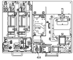
도 1d는 예시적인 모듈식 광학 분석 시스템의 블록도를 도시한다. 일부 구현예들에서, 모듈식 광학 분석 시스템은 내부에 배치된 두 개의 광원들(1650 및 1660)을 갖는 LGM(1182)을 포함할 수도 있다. 광원들(1650 및 1660)은 레이저 다이오드들, 다이오드 펌핑식 고체 상태 레이저들, 또는 본 기술분야에서 공지된 바와 같은 다른 광원들일 수도 있는데, 이들 광원들은 상이한 파장들(예컨대, 적색 또는 녹색 광)의 레이저 빔들을 출력한다. 레이저 소스들(1650 및 1660)로부터 출력된 광 빔들은 빔 성형 렌즈 또는 렌즈들(1604)을 통해 진행될 수도 있다. 일부 구현예들에서, 단일 광 성형 렌즈가 양 광원들로부터 출력되는 광 빔들을 성형하는데 사용될 수도 있다. 다른 구현들에서, 별도의 빔 성형 렌즈가 각각의 광 빔을 위해 사용될 수도 있다. 일부 예들에서, 빔 성형 렌즈는 파월 렌즈라서, 광 빔들이 라인 패턴들로 성형된다.Figure 1D shows a block diagram of an exemplary modular optical analysis system. In some implementations, the modular optical analysis system may include an
LGM(1182)은 거울들(1001, 1002, 1003, 및 1004)을 추가로 포함할 수도 있다. 광원(1650)에 의해 생성된 광 빔이 거울(1004)의 개구부 또는 반-반사(semi-reflective) 표면을 통하여, 그리고 단일 인터페이스 포트를 통하여 EOM(1188)으로 진행되기 위해 거울(1001)과 거울(1002)에서 반사할 수도 있다. 마찬가지로, 광원(1660)에 의해 생성된 광 빔이 단일 인터페이스 포트를 통해 EOM(1188)으로 진행되도록 하기 위해 거울(1003)과 거울(1004)에서 반사할 수도 있다. 일부 예들에서, 교합 거울들의 추가적인 세트가, 예를 들어, 도 1h에 예시된 바와 같이, 추가적인 튜닝 표면들을 제공하기 위해 거울들(1003 및 1004)에 인접하여 통합될 수도 있다.
양 광 빔들은 이색 거울(1004)을 사용하여 결합될 수도 있다. 양 광 빔들은 라인 형성 광학계, 이를테면 파월 렌즈를 통해 진행될 수도 있다. 거울들(1001, 1002, 1003, 및 1004)은 각각이 광원들(1650 및 1660)로부터의 광 빔들을 정렬하기 위해 수동 또는 자동화된 제어들을 사용하여 교합하도록 구성될 수도 있다. 광 빔들은 셔터 엘리먼트(1006)를 통과할 수도 있다. EOM(1188)은 대물렌즈(1404)와 대물렌즈(1404)를 길이방향으로 타겟(1192)에 더 가깝게 또는 그로부터 더 멀어지게 이동시키는 z-스테이지(1024)를 포함할 수도 있다. 예를 들어, 타겟(1192)은 액체 층(1550)과 반투명 덮개 판(1504)을 포함할 수도 있고, 생물학적 샘플이 액체 층 아래에 위치된 기판 층의 내부 표면 뿐만 아니라 반투명 덮개 판의 내부 표면에 위치될 수도 있다. z-스테이지는 그 다음에 (예컨대, 생물학적 샘플 상에 포커싱된) 흐름셀의 어느 하나의 내부 표면 상에 광 빔들을 포커싱하기 위해 대물렌즈를 이동시킬 수도 있다. 생물학적 샘플은 본 기술분야에서 공지된 바와 같은 광학적 시퀀싱에 응답하는 DNA, RNA, 단백질들, 또는 다른 생물학적 재료들일 수도 있다. 일부 구현예들에서, 대물렌즈는 광 빔들을 흐름셀 넘어서는 초점에 포커싱하도록, 이를테면 흐름셀의 표면들에서 광 빔들의 라인 폭을 증가시키도록 구성될 수도 있다.Both light beams may be combined using a
EOM(1188)은 타겟(1192)으로부터 되돌아온 광이 통과하는 것을 허용하면서도, 대물렌즈(1404)를 통하여 광을 진행시키는 반-반사 거울(1020)을 또한 포함할 수도 있다. 일부 구현예들에서, EOM(1188)은 튜브 렌즈(1406)와 교정 렌즈(1450)를 포함할 수도 있다. 교정 렌즈(1450)는 정확한 이미징을 보장하기 위해, 예컨대, 대물렌즈(1404)를 이동시킴으로써, 그리고/또는 더 두꺼운 기판을 통한 이미지화로부터 야기된 구면수차를 정정하기 위해 z-스테이지(1022)를 사용하여 대물렌즈(1404)에 더 가깝거나 또는 더 멀어지게 중 어느 하나로 길이방향으로 교합될 수도 있다. 교정 렌즈(1450) 및 튜브 렌즈(1406)를 투과한 광은 그 다음에 필터 엘리먼트(1012)를 통과하고 CAM(1186) 속으로 전달될 수도 있다. CAM(1186)은 입사 광 빔들에 응답하여 생물학적 샘플로부터 방출된 광을 검출하는 하나 또는 그 초과의 광 센서들(1050)을 포함할 수도 있다.The
일부 예들에서, EOM(1188)은 FTM(1184)으로부터 방출된 초점 추적 광 빔을 타겟(1192) 상으로 반사시킨 다음, 타겟(1192)으로부터 반환되는 광을 FTM(1184)으로 다시 반사시키는 반-반사 거울(1018)을 추가로 포함할 수도 있다. FTM(1184)은 반환된 초점 추적 광 빔의 특성들을 검출하고 타겟(1192) 상의 대물렌즈(1404)의 초점을 최적화하기 위한 피드백 신호를 생성하는 초점 추적 광 센서를 포함할 수도 있다.In some instances, the
LGM(1182)은 대물렌즈를 통해 균일한 라인 조명을 생성하도록 구성된다. 예를 들어, 대물렌즈는, LGM이 조립되고 있거나 또는 유지보수되고 (예컨대, 모듈식 광학 분석 시스템과는 물리적으로 분리되어) 있을 때 LGM의 내부 컴포넌트들을 정렬하기 위해 사용되는 LGM 정렬 시스템 상에 또는, EOM(1188) 상에 위치될 수도 있다. LGM은 단일 또는 거의-단일 모드 레이저 광원들로부터의 레이저 빔들을 확산 및/또는 성형하기 위해 하나 또는 그 초과의 파월 렌즈들을 사용할 수도 있다. 액티브 빔 확장기, 감쇠기, 하나의 릴레이 렌즈들, 실린더형 렌즈들, 교합식 거울들, 회절 엘리먼트들, 및 산란 컴포넌트들과 같은 다른 빔 성형 광학계가 균일성을 제어하고 허용오차를 증가시키는데 사용될 수도 있다. 레이저 빔들은 (예컨대, 도 1j에 예시된 바와 같이) 흐름셀 표면들 상에서 더 나은 허용오차를 제공하기 위해 대물렌즈의 후방 초점에서 교차할 수도 있다. 파월 렌즈가 대물렌즈 근처, 또는 릴레이 렌즈 근처에 위치될 수도 있다. 이미징 광학계에 들어가는 레이저 빔의 팬 각도는 이미징 광학계의 시야를 일치시키기 위해 조정될 수도 있다.The
레이저 빔들의 방향, 사이즈, 및/또는 편광은 렌즈들, 거울들, 및/또는 편광기들을 사용함으로써 조정될 수도 있다. 광학 렌즈들(예컨대, 실린더형, 구형, 또는 비구면)은 흐름셀 타겟의 이중 표면들 상에서 조명 초점을 능동적으로 조정하는데 사용될 수도 있다. LGM(1182) 상의 광 모듈들은 현장 서비스를 위해 개별적으로 대체될 수도 있다. LGM(1182)은 다수의 유닛들을 포함할 수도 있고 각각의 유닛은 특정/상이한 파장들 및 편광을 위해 설계된다. 다수의 유닛들을 적층하는 것은 레이저 출력 및 파장 옵션들을 증가시키는데 사용될 수도 있다. 둘 이상의 레이저 파장들이 이색거울들 및 편광기들로 결합될 수도 있다.The direction, size, and / or polarization of the laser beams may be adjusted by using lenses, mirrors, and / or polarizers. Optical lenses (e.g., cylindrical, spherical, or aspherical) may be used to actively adjust the illumination focus on the dual surfaces of the flow cell target. The optical modules on the
형광소들의 광-포화 또는 인접한 영역 상의 광퇴색을 피하기 위해, 조명 라인 프로파일들이 이미징 지역 내부/외부의 미리 결정된 세기 비율 허용오차들 내에 속하도록 조정될 수도 있다. 흐름셀 및/또는 센서에서 레이저 라인 패턴들을 광폭화함으로써, 더 높은 스캔 속력들 및 레이저 출력들이 채용될 수도 있다(예컨대, 전력 및 쓰루풋은 광-포화 또는 광퇴색을 경험하거나, 또는 레이저 모듈들을 손상시키지 않고 4-배를 초과하여 증가될 수도 있다). 일부 예들에서, 흐름셀에서 20 kW/cm2을 초과하는 레이저 전력 밀도들이 흐름셀에서 형광소들을 과-포화시킬 수도 있다. 이것이 발생할 때, 센서에서 검출되는 방출 신호는 레이저 모듈들로부터의 여기 전력에서의 증가와 함께 선형적으로 증가하지 않을 것이다.In order to avoid photo-discoloration on the photo-saturated or adjacent areas of the fluorophores, the illumination line profiles may be adjusted to fall within predetermined intensity ratio tolerances inside / outside the imaging area. By widening the laser line patterns in the flow cell and / or the sensor, higher scan speeds and laser outputs may be employed (e.g., power and throughput may experience light-saturated or light discoloration, And may be increased by more than 4-fold). In some instances, laser power densities in the flow cell exceeding 20 kW / cm < 2 > may over-saturate the fluorophore in the flow cell. When this happens, the emission signal detected at the sensor will not increase linearly with an increase in the excitation power from the laser modules.
광학계를 사용하여 조명 라인들을 광폭화하는 방법들은 파월 렌즈 후 또는 전에 디포커스 렌즈, 프리즘 어레이, 또는 확산기를 추가하는 것을 포함할 수도 있다. 일부 구현예들에서, 이들 방법들은 레이저 조명 빔 사이즈를 감소시키는 것 그리고/또는 대물렌즈 무한 켤레 설계를 감소시키는 것을 또한 포함할 수도 있다. 도 1k는 광-포화 및 광퇴색을 피하기 위해 흐름셀 상에서 레이저 라인 패턴을 광폭화하는데 사용되는 LGM 및 EOM 시스템의 블록도를 도시한다. 흐름셀 상에 입사하는 레이저 빔 라인 폭은 여기 전력 밀도를 감소시키고 광-포화를 피하기 위해 증가될 수도 있다. 라인 폭은, 예를 들어, 디포커스 렌즈, 프리즘, 어레이, 또는 확산기를 파월 렌즈 앞이나 또는 뒤에 중 어느 하나에 통합함으로써 증가될 수도 있다. 일부 구현예들에서, 라인 폭은 흐름셀의 표면들 너머로 라인 패턴을 포커싱하기 위해 (예컨대, 대물렌즈를 z-축에서 이동시키는) 도 1k에 예시된 바와 같이 대물렌즈를 디포커싱함으로써 증가될 수도 있다. 일부 예들에서, 흐름셀의 원단 표면으로부터 약 50 미크론과 약 150 미크론 사이의 거리로 라인 패턴을 디포커싱하는 것은 10 미크론보다 큰 라인 폭을 생성하고, 광-포화 및 광퇴색 효과들을 효과적으로 감소시킬 수도 있다.Methods of widening the illumination lines using an optical system may include adding defocus lenses, prism arrays, or diffusers after or before the powell lens. In some implementations, these methods may also include reducing the laser illumination beam size and / or reducing the objective infinite pair design. Figure 1K shows a block diagram of an LGM and EOM system used to broaden a laser line pattern on a flow cell to avoid photo-saturation and light discoloration. The width of the laser beam line incident on the flow cell may be increased to reduce excitation power density and avoid photo-saturation. The line width may be increased, for example, by incorporating defocus lenses, prisms, arrays, or diffusers either before or behind the powell lens. In some implementations, the line width may be increased by defocusing the objective lens as illustrated in Figure 1K (e.g., moving the objective in the z-axis) to focus the line pattern beyond the surfaces of the flow cell have. In some instances, defocusing the line pattern at a distance of between about 50 microns and about 150 microns from the far-end surface of the flow cell produces a line width of greater than 10 microns and may effectively reduce light-saturation and photo- have.
TDI 센서를 사용할 때, 라인 폭-대-빔 세기 프로파일은 TDI 센서의 신호 대 잡음 허용오차들로 균형을 이룰 수도 있다. 예를 들어, 매우 넓은 라인 폭들에서, 신호 대 잡음 비는 효과적이기에는 너무 낮을 수도 있다.When using a TDI sensor, the line width-to-beam intensity profile may balance the signal-to-noise tolerances of the TDI sensor. For example, at very wide line widths, the signal-to-noise ratio may be too low to be effective.
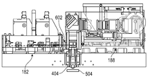
도 1f는 LGM 정렬 시스템의 블록도를 예시한다. 도 1g는 LGM 정렬 시스템의 사시도를 예시한다. 예시된 바와 같이, 일부 구현예들에서, 녹색 레이저 모듈이 두 개의 PZT 거울들에서 반사하는 제 1 레이저 빔을 생성할 수도 있다. 마찬가지로, 적색 레이저 모듈이 두 개의 PZT 거울들에서 또한 반사하는 그리고 제 1 레이저 빔과 결합하는 제 2 레이저 빔을 생성할 수도 있다. 양 레이저 빔들은 그 다음에 라인 패턴을 생성하기 위해 파월 렌즈를 통과한 다음, 셔터, EOM 광학계, 및 대물렌즈를 통과할 수도 있다. 일부 구현예들에서, 레이저 빔들은 레이저 빔들의 라인 폭을 증가시키기 위해 대물렌즈를 통과하기 전에 디포커스 렌즈를 사용하여 디포커싱될 수도 있다. 대안적으로, 레이저 빔들은 대물렌즈를 z-축에서 교합시킴으로써 디포커싱될 수도 있다. 흐름셀의 표면들을 넘어서는 초점에 레이저 빔들을 포커싱함으로써, 레이저 라인들은 샘플에서 에너지를 분산시키고 높은 스캐닝 속력들 및 높은 레이저 전력들에서 광-포화, 광퇴색, 및 레이저 손상을 피하기 위해 광폭화될 수도 있다. 일부 구현예들에서, 라인 패턴들은 5 미크론 미만부터 13 미크론 초과까지의 폭으로 증가될 수도 있다.Figure 1F illustrates a block diagram of an LGM alignment system. Figure 1G illustrates a perspective view of the LGM alignment system. As illustrated, in some embodiments, a green laser module may produce a first laser beam that is reflected at two PZT mirrors. Likewise, a red laser module may also produce a second laser beam that also reflects in the two PZT mirrors and couples with the first laser beam. Both laser beams may then pass through a power lens to produce a line pattern, and then through a shutter, an EOM optical system, and an objective lens. In some embodiments, the laser beams may be defocused using a defocus lens before passing through the objective lens to increase the line width of the laser beams. Alternatively, the laser beams may be defocused by occluding the objective lens in the z-axis. By focusing the laser beams at focal points beyond the surfaces of the flow cell, the laser lines may be widened to disperse energy in the sample and avoid photo-saturation, light fade, and laser damage at high scanning speeds and high laser powers . In some embodiments, the line patterns may be increased in width from less than 5 microns to more than 13 microns.
LGM 정렬 시스템은 LGM에서의 거울들(1001, 1002, 1003, 및 1004), 뿐만 아니라 렌즈들, 레이저들, 또는 다른 컴포넌트들 또는 광학계의 상대 포지셔닝을 조정 또는 조작하기 위한 제어 표면들을 포함할 수도 있다. 예를 들어, 조정들은 제어 노브들, 스크류들, 또는 다른 컴포넌트들의 수동 조작을 사용하여 이루어질 수도 있다. 다른 구현예들에서, 광학 컴포넌트들 중 하나 또는 그 초과의 광학 컴포넌트는 자동으로 조정되거나 또는 조작될 수도 있다. 자동 제어 디바이스들은 동력식 병진 스테이지, 작동 디바이스, 하나 또는 그 초과의 피에조 스테이지들, 및/또는 하나 또는 그 초과의 자동 스위치 및 플립 거울들 및 렌즈들을 포함할 수도 있다. 소프트웨어 인터페이스가 모든 디바이스들, 테스트 시스템, 교정, 및 테스트 절차를 제어하는데 사용될 수도 있다. 정렬 시스템은 빔 프로파일러(예컨대, 2D 이미징 센서), 결상 렌즈(EOM 대물렌즈를 대체함), 감쇠기, 및/또는 정렬 타겟들을 포함한다. 소프트웨어 인터페이스는 품질 제어 및 제품 평가에 대한 보고서들을 출력하는데 사용될 수도 있다. 예를 들어, 보고들은 LGM의 광학 컴포넌트들의 각각의 정렬 구성을 기준으로 하는 빔 세기 및 프로파일에 관련한 빔 프로파일러에 의해 생성된 데이터를 포함할 수도 있다.The LGM alignment system may include control surfaces for adjusting or manipulating the relative positioning of the
일부 구현예들에서, LGM 정렬 시스템을 사용하여 LGM을 정렬하는 방법은, LGM 정렬 시스템을 기준으로 이미징 광학계, 센서들, 및 기계에 대한 합리적인 정렬 포지션들 및 허용오차들을 식별하는 것을 포함할 수도 있다. LGM 정렬 시스템은 모듈식 광학 분석 시스템 외부에 있다. 이와 같이, LGM의 내부 컴포넌트들은 모듈식 광학 분석 시스템에서의 설치에 앞서 조립되고 정렬될 수도 있다. LGM의 내부 컴포넌트들은 유지보수 활동 동안 또한 정렬될 수도 있다.In some implementations, the method of aligning the LGM using the LGM alignment system may include identifying reasonable alignment positions and tolerances for the imaging optics, sensors, and machine, based on the LGM alignment system . The LGM alignment system is outside the modular optical analysis system. As such, the internal components of the LGM may be assembled and aligned prior to installation in a modular optical analysis system. The internal components of the LGM may also be aligned during maintenance activities.
일부 구현예들에서, LGM 광학 컴포넌트들의 정렬은 시퀀싱 동안 또는 시퀀싱 사이클들/런들 사이의 자동 추적 및 조정을 위한 작동되는 디바이스들을 사용하여 완수될 수도 있다. 예를 들어, 작동된 디바이스들은 피에조 스테이지, 동력식 액추에이터, 또는 본 기술분야에서 공지된 유사한 디바이스들일 수도 있다. 작동된 디바이스들은 온도 변화들, 뿐만 아니라 레이저들, 렌즈, 및 마운트들을 포함하는 광학 컴포넌트들의 붕괴에 의해 야기된 드리프트를 또한 보상할 수도 있다.In some implementations, the alignment of the LGM optical components may be accomplished using sequenced devices or working devices for automatic tracking and adjustment between sequencing cycles / runs. For example, the actuated devices may be piezo stages, powered actuators, or similar devices known in the art. The actuated devices may also compensate for temperature drifts, as well as drift caused by the collapse of optical components, including lasers, lenses, and mounts.
각각의 광학 컴포넌트는 정밀 접촉 패드들, 도웰(dowel) 핀들, 스톱퍼들, 또는 본 기술분야에서 공지된 바와 같은 다른 정밀 기계 장착 표면들과의 기계적 인터페이스를 사용하여 인클로저 또는 광학 프레임에 기계적으로 커플링할 수도 있다.Each optical component is mechanically coupled to the enclosure or optical frame using mechanical interfaces with precision contact pads, dowel pins, stoppers, or other precision mechanical mounting surfaces as known in the art You may.
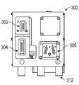
도 2a와 도 2b는 EOM(188) 상의 정밀 장착 구조들을 예시하는 도면들이다. 여러 구현예들에서, EOM(188)은 EOM 인클로저(210)를 포함할 수도 있다. EOM(188)은 LGM(182), FTM(184), 및 CAM(186)에 기계적으로 및 광학적으로 커플링할 수도 있다(예컨대, EOM(188)의 인클로저는 LGM(182) 및/또는 FTM(184)에서의 광원(들)에 의해 생성된 광이, EOM(188)의 개구부들 및 내부 광학계를 통과하는 것을 가능하게 하는, 다른 모듈식 서브어셈블리들 중 각각의 모듈식 서브어셈블리의 인클로저 상에 위치된 개구부에 대응하고 그 개구부와 정렬되는 하나 또는 그 초과의 개구부들을 포함할 수도 있다). 도 2b에 예시된 바와 같이, EOM 인클로저(210)는, FTM(184)의 인클로저의 외부 표면 상에 위치된 대응하는 정밀 장착 구조체들에 정렬되고 기계적으로 커플링하도록 (예컨대, 물리적으로 부착하도록) 구성되는 FTM 정밀 장착 구조체들(212)을 포함할 수도 있다. 마찬가지로, EOM 인클로저(210)는 CAM(186)의 인클로저(220)의 외부 표면 상에 위치된 대응하는 정밀 장착 구조체들에 정렬되고 기계적으로 커플링하도록 구성되는 CAM 장착 구조체들(222)을 포함할 수도 있다.2A and 2B are views illustrating precise mounting structures on the
도 3a, 도 3b, 및 도 3c는 FTM(184) 상의 정밀 장착 구조체들을 예시하는 도면들이다. 도 3a를 참조하면, FTM(184)은 FTM 인클로저(300) 내에 위치되는 광원과 광 센서들을 포함할 수도 있다. FTM 인클로저(300)는 광원 및 광 센서들을 제어하는 전자 인터페이스들(302, 304, 및 306)을 위한 인터페이스 포트들을 포함할 수도 있다. FTM 인클로저(300)는 정밀 장착 구조체들(312)(예컨대, 정밀 장착 플레이트(190) 상의 미리 결정된 로케이션들 또는 함요부들에 기계적으로 커플링하도록 구성되는 정밀 장착 발들)을 또한 포함할 수도 있다. FTM 인클로저(300)는 EOM 인클로저(210)의 외부 표면 상에 위치된 대응하는 정밀 장착 구조체들(212)에 정렬되고 기계적으로 커플링하도록 구성되는 정밀 장착 구조체들(314)을 추가로 포함할 수도 있다.FIGS. 3A, 3B, and 3C are views illustrating precisely mounted structures on the
시스템 정렬을 지원하기 위해 각각의 모듈식 서브어셈블리를 미리-조립, 구성, 정렬 및 테스트한 다음, 각각을 정밀 장착 플레이트(190)에 장착하는 것은, 원하는 허용오차들을 충족시키기 위해 요구된 설치 후 정렬의 양을 감소시킬 수도 있다. 하나의 예에서, EOM(188)과 다른 서브어셈블리 모듈들 중 각각의 서브어셈블리 모듈 사이의 설치 후 정렬은 대응하는 모듈 포트들(예컨대, EOM/FTM 포트, EOM/CAM 포트, 및 EOM/LGM 포트)을 인터페이싱한 다음, 각각의 모듈식 서브어셈블리의 포지션(X, Y, 또는 Z 축에서임), 각도(X 또는 Y 방향에서임), 및 회전을 수동으로 또는 자동으로 교합시킴으로써 모듈식 서브어셈블리들을 서로에 대해 정렬하는 것에 의해 완수될 수도 있다. 자유도들의 일부는 정밀 장착 플레이트(190) 및 인접한 모듈식 서브어셈블리들에 관하여 모듈식 서브어셈블리의 포지션 및 배향을 미리 결정하는 정밀 정렬 구조체들에 의해 제한될 수도 있다. 시스템(180)의 내부 광학계를 튜닝 및 정렬하는 것은 그러면 (예컨대, 어느 하나의 X, Y, 또는 Z 거울들 및 렌즈들을 틸팅 또는 이동시킴으로써) 모듈식 서브어셈블리들 내부의 컴포넌트들을 교합시킴으로써 완수될 수도 있다.Assembling, configuring, aligning, and testing each modular subassembly to support system alignment, and then mounting each of them onto
도 4a는 예시적인 모듈식 광학 분석 시스템을 도시하는 측면도이다. 도 4a에 예시된 바와 같이, LGM(182)과 EOM(188)은 정밀 장착 플레이트(190)에, 뿐만 아니라 서로에 대해 정렬되고 기계적으로 커플링될 수도 있다. EOM(188)은 거울(408)을 통해 튜브 렌즈(406)와 정렬된 대물렌즈(404)를 포함할 수도 있는데, 그 튜브 렌즈는 LGM(182)에 결국 광학적으로 커플링되어서, LGM(182)에 의해 생성된 광 빔들은 LGM(182)과 EOM(188) 사이의 인터페이스 배플을 투과하며, 대물렌즈(404)를 통과하고, 광학 타겟을 때린다. 타겟으로부터의 응답성 광 방사는 그러면 대물렌즈(404)를 다시 통과하고 튜브 렌즈(406)로 전달될 수도 있다. 튜브 렌즈(406)는 흐름셀 기판 또는 덮개 유리의 변화된 두께를 통해 결상하는 대물렌즈(404)에 의해 도입된 구면수차 아티팩트들을 정정하기 위해 z-축을 따라 교합하도록 구성되는 렌즈 엘리먼트(450)를 포함할 수도 있다. 예를 들어, 도 4b와 도 4c는 튜브 렌즈(406)의 상이한 구성들을 예시하는 블록도들이다. 예시된 바와 같이, 렌즈 엘리먼트(450)는 빔 성형 및 경로를 조정하기 위해 대물렌즈(404)에 더 가까이 또는 그로부터 더 멀어지게 교합될 수도 있다.4A is a side view illustrating an exemplary modular optical analysis system. As illustrated in FIG. 4A,
일부 구현예들에서, EOM(188)은, 예컨대 정렬 스테이지(192) 상의 액추에이터들에 의해 제어되는, z-스테이지에 기계적으로 커플링될 수도 있다. 일부 예들에서, z-스테이지는 정밀 코일에 의해 교합되고, 흐름셀 상에 초점을 유지하기 위해 대물렌즈(404)를 조정 및 이동시킬 수도 있는 포커싱 메커니즘에 의해 작동될 수도 있다. 예를 들어, 초점을 조정할 것을 제어하는 신호는 FTM(184)으로부터 출력될 수도 있다. 이 z-스테이지는 예를 들어 대물렌즈(404), 튜브 렌즈(406), 및/또는 렌즈 엘리먼트(450)를 교합시킴으로써 EOM 광학계를 정렬시킬 수도 있다.In some implementations, the
도 5a와 도 5b는 FTM(184)을 예시하는 도면들이다. FTM(184)은 FTM/EOM 인터페이스 포트(502)를 통해 EOM(188)과 인터페이싱할 수도 있다. 도 5a에 예시된 바와 같이, FTM(184)에서 유래하고 EOM(188)의 광학계를 통과하는 광 빔들은 흐름셀(504)에서 반사할 수도 있다. 본 명세서에서 개시되는 바와 같이, FTM(184)은 시스템(180) 전체를 통해 광학 컴포넌트들의 정렬 및 포지셔닝을 제어하기 위하여 컴퓨터 프로세서에 피드백을 제공하도록 구성될 수도 있다. 예를 들어, FTM(184)은 대물렌즈(404)를 통과하고 흐름셀(504)에서 반사하는 둘 이상의 평행한 광 빔들을 사용하는 초점 메커니즘을 채용할 수도 있다. 최적의 초점 포지션에서부터 멀어지는 흐름셀의 이동은 반사된 빔들이 대물렌즈(404)를 나갈 때 각도를 변화시키게 할 수도 있다. 그 각도는 FTM(184)에 위치된 광 센서에 의해 측정될 수도 있다. 일부 예들에서, 광 센서 표면과 대물렌즈(404) 사이의 광경로의 거리는 300 mm와 700 mm 사이의 거리일 수도 있다. FTM(184)은 EOM에서의 z-스테이지를 사용하여 대물렌즈(404)의 포지션을 조정함으로써 둘 이상의 평행한 광 빔들의 빔 스폿 패턴들 사이에 미리 결정된 측방향 분리를 유지하기 위해 광 센서로부터의 출력 신호를 사용하는 피드백 루프를 개시할 수도 있다.5A and 5B are views illustrating the
시스템(180)의 일부 구현예들은 흐름셀(504)의 상단 및 하단 표면 이미징을 위한 보상 방법을 제공한다. 일부 예들에서, 흐름셀(504)은 한 층의 액체와 기판 상에 층을 이루는 덮개 유리를 포함할 수도 있다. 예를 들어, 덮개 유리는 약 100 ㎛와 약 500 ㎛ 사이의 두께일 수도 있으며, 액체 층은 약 50 ㎛와 약 150 ㎛ 사이의 두께일 수도 있고, 기판은 약 0.5와 약 1.5 mm 사이의 두께일 수도 있다. 하나의 예에서, DNA 샘플이 액체 채널의 상단 및 하단에(예컨대, 기판의 상단, 그리고 덮개 유리의 하단에) 도입될 수도 있다. 그 샘플을 분석하기 위해, 흐름셀(504)의 다양한 깊이들에서 입사 광 빔들의 초점은 (예컨대, 기판의 상단 또는 덮개 유리의 하단 상에 포커싱하기 위해) z-스테이지를 이동시킴으로써 조정될 수도 있다. 흐름셀(504) 내에서 입사 빔 초점들을 변화시키는 대물렌즈(404)의 이동은 이미징 아티팩트들 또는 결함들, 이를테면 구면수차를 도입할 수도 있다. 이들 아티팩트들 또는 결함들을 수정하기 위해, 튜브 렌즈(406) 내의 렌즈 엘리먼트(450)는 대물렌즈(404)에 더 가깝게 또는 그로부터 더 멀어지게 이동될 수도 있다.Some embodiments of the
일부 예들에서 FTM(184)은 교체가능 내부 컴포넌트들이 없는 단일 FRU로서 구성될 수도 있다. FTM 내부 컴포넌트들, 이를테면 레이저의 수명 및 신뢰도를 증가시키기 위해, 레이저 출력은 (예를 들어, 5 mW 미만으로) 감소될 수도 있다.In some instances, the
도 6과 도 7은 LGM(182)과 EOM(188)을 예시하는 도면들이다. 예시된 바와 같이, LGM(182)은 LGM/EOM 인터페이스 배플(602)을 통해 EOM(188)과 인터페이싱할 수도 있다. LGM(182)은 시스템(180)을 위한 광자 소스이다. 하나 또는 그 초과의 광원들(예컨대, 광원들(650 및 660))이 LGM(182)의 인클로저 내부에 위치될 수도 있다. 광원들(650 및 660)로부터 생성된 광은 빔 성형 렌즈(604)를 통과하고 LGM/EOM 인터페이스 배플(602)을 통하여 EOM(188)의 광경로 속으로 진행될 수도 있다. 예를 들어, 광원(650)은 녹색 레이저일 수도 있고 광원(660)은 적색 레이저일 수도 있다. 레이저들은 (예컨대, 3 와트를 초과하는) 높은 전력들에서 동작할 수도 있다. 하나 또는 그 초과의 빔 성형 렌즈들(604)이 광원들로부터 생성된 광 빔들을 원하는 형상들(예컨대, 라인)로 성형하도록 구현될 수도 있다.FIGS. 6 and 7 illustrate
광원들(650 및 660)에 의해 생성된 광자들(예컨대, 녹색 파장 광자들 및 적색 파장 광자들)은 흐름셀(504) 상에 위치된 DNA에서의 형광소들을 여기시켜 DNA 내에 존재하는 염기쌍들의 분석을 가능하게 할 수도 있다. 고속 시퀀싱이 CAM(186)에서의 광 센서들에 의해 검출될 DNA 샘플로부터의 반응성 광자들의 충분한 방출을 자극하기 위해, 충분한 광자 선량(dose)을 DNA 형광소들에 전달하는 고속 스캐닝을 채용한다.The photons (e.g., green wavelength photons and red wavelength photons) generated by light sources 650 and 660 excite fluorophores in DNA located on
빔 성형 렌즈(604)는 레이저들(650 및 660)에 의해 방출된 가우시안 광을 라인을 닮은 균일한 프로파일(길이 방향에서임)로 확산시키는 파월 렌즈일 수도 있다. 일부 구현예들에서, 단일 빔 성형(604) 렌즈는 각각의 입사 레이저 빔에 대해 레이저 광의 별도의 라인을 생성하기 위해 상이한 미리 결정된 각도들(예컨대, 각도의 부분을 더하거나 또는 뺌)에서 빔 성형 렌즈(604)의 앞쪽에 입사될 수도 있는 다수의 광 빔들(예컨대, 적색 광 빔 및 녹색 광 빔 둘 다)을 위해 사용될 수도 있다. 광의 라인들은 CAM(186)에서의 다수의 광 센서들에 의한 각각의 광 빔에 대응하는 별개의 신호들의 확실한 검출을 가능하게 하는 미리 결정된 거리만큼 분리될 수도 있다. 예를 들어, 녹색 광 빔이 CAM(186)에서의 제 1 광 센서 상에 궁극적으로 입사될 수도 있고 제 2 광 빔이 CAM(186)에서의 제 2 광 센서 상에 궁극적으로 입사될 수도 있다.The
일부 예들에서, 적색 및 녹색 광 빔들은 그것들이 빔 성형 렌즈(604)에 입사할 때 일치/중첩된 다음 그것들이 대물렌즈(404)에 도달할 때 각각의 라인 형상들로 펼쳐지기 시작할 수도 있다. 빔 성형 렌즈의 포지션은 빔 발산을 제어하고 광 빔들의 성형을 최적화하기 위해 광원들(650 및 660) 근처에서 또는 그들 광원들에 가까이 근접하여 엄격한 허용오차로, 즉, 임의의 광을 자르지 않고 전체 빔 형상이 대물렌즈(404)를 통과하는 것을 여전히 가능하게 하면서도 충분한 빔 형상(예컨대, 광 빔에 의해 투영된 라인의 길이)을 제공함으로써 제어될 수도 있다. 일부 예들에서, 빔 성형 렌즈(604)와 대물렌즈(404) 사이의 거리는 약 150 mm 미만이다.In some instances, the red and green light beams may coincide / overlap as they enter the
일부 구현예들에서, 시스템(180)은 광학 타겟을 수용하는 주머니를 갖는 모듈식 서브어셈블리를 더 포함할 수도 있다. 본체는 약 6.0% 이하의 반사율을 갖는 안료를 포함하는 알루미늄을 포함할 수도 있다. 본체는 상단 표면에 그리고 주머니 주위에 위치된 인셋(inset) 지역을 포함할 수도 있다. 모듈식 서브어셈블리는 인셋 지역에 장착된 투명 격자 층(grating layer)을 더 포함할 수도 있고 광학 타겟 위쪽에 위치되고 광학 타겟으로부터 프린지 갭만큼 이격될 수도 있다. 본체는 광학 타겟을 수용하는 주머니를 포함할 수도 있다. 본체는 광학 타겟 아래에 위치된 확산 웰을 포함할 수도 있다. 확산 웰은 광학 타겟을 통과하는 여기 광을 수용할 수도 있다. 확산 웰은 약 6.0% 이하의 반사율을 나타내는 안료 계 마감재를 갖는 웰 바닥을 포함할 수도 있다.In some implementations, the
시스템(180)의 모듈식 서브어셈블리들 중 하나의 모듈식 서브어셈블리는 광 검출 디바이스를 더 포함할 수도 있다. 대물렌즈(404)는 여기 광을 광학 타겟을 향하여 방출하고 광학 타겟으로부터 형광 방출을 수신할 수도 있다. 액추에이터가 광학 타겟에 근접한 관심 있는 지역에 대물렌즈(404)를 포지셔닝하도록 구성될 수도 있다. 프로세서는 그러면 기구의 광학적 정렬 및 교정 중 적어도 하나에 관련하여 광학 타겟으로부터 형광 방출을 검출하기 위한 프로그램 명령들을 실행할 수도 있다.The modular subassembly of one of the modular subassemblies of
일부 예들에서, 대물렌즈(404)는 여기 광을 광학 타겟 상으로 진행시킬 수도 있다. 프로세서는 형광 방출로부터 참조 정보를 도출할 수도 있다. 프로세서는 기구의 광학적 정렬 및 교정 중 적어도 하나에 관련하여 참조 정보를 이용할 수도 있다. 광학 타겟은 대물렌즈(404) 근처의 교정 로케이션에 영구적으로 장착될 수도 있다. 교정 로케이션은 흐름셀(504)로부터 분리할 수도 있다. 고체 본체가 입체 호스트 재료와 그 호스트 재료에 삽입된 형광 재료를 포함하는 기판을 나타낼 수도 있다. 고체 본체는 여기 광에 의해 조사될 때 관심 있는 하나 또는 그 초과의 미리 결정된 방출 대역들에서 형광을 방출하는 양자점들을 둘러싸는 에폭시 또는 폴리머 중 적어도 하나를 나타낼 수도 있다.In some examples, the
도 8은 모듈식 광학 분석 시스템(800)을 설치 및 구성하기 위한 예시적인 프로세스를 도시하는 도면이다. 프로세스(800)는 단계 805에서 제 1 서브어셈블리 내에 복수의 광원들과 빔 성형 렌즈를 포지셔닝하는 것을 포함할 수도 있다. 예를 들어, 복수의 광원들은 광원(650)과 광원(660)을 포함할 수도 있다. 제 1 서브어셈블리는 광원들이 장착되고 정렬되는 LGM 인클로저를 포함할 수도 있는 LGM일 수도 있다. 빔 성형 렌즈는, LGM 인클로저 내에 또한 장착되는, 그리고, 광원들(650 및 660)에 의해 생성된 광 빔들을 별개의 라인 패턴들로 성형하도록 구성되는 파월 렌즈일 수도 있다.FIG. 8 is a diagram illustrating an exemplary process for installing and configuring the modular
프로세스(800)는 단계 815에서 제 2 서브어셈블리 내에 튜브 렌즈와 대물렌즈를 포지셔닝하는 것을 또한 포함할 수도 있다. 예를 들어, 제 2 서브어셈블리는 EOM일 수도 있고, 대물렌즈 및 튜브 렌즈가 장착되고 정렬되는 EOM 인클로저를 포함할 수도 있다.The
프로세스(800)는 단계 825에서 제 3 서브어셈블리 내에 복수의 광 센서들을 포지셔닝하는 것을 또한 포함할 수도 있다. 예를 들어, 제 3 서브어셈블리는 CAM일 수도 있고, 광 센서들이 정렬되고 장착되는 CAM 인클로저를 포함할 수도 있다. 단계 805로부터의 각각의 광원에 대해 대응하는 광 센서가 있을 수도 있다.The
프로세스(800)는 단계 835에서 제 4 서브어셈블리 내에 초점 추적 광원과 광 센서를 포지셔닝하는 것을 또한 포함할 수도 있다. 예를 들어, 제 4 서브어셈블리는 FTM일 수도 있고, 초점 추적 광원 및 광 센서가 장착되는 FTM 인클로저를 포함할 수도 있다.The
일부 구현예들에서, 프로세스(800)는 단계 845에서 각각의 서브어셈블리를 개별적으로 테스트하는 것을 추가로 포함할 수도 있다. 예를 들어, 테스팅은 서브어셈블리의 인클로저에 각각의 서브어셈블리의 내부 컴포넌트들을 정확히 튜닝 및/또는 정렬하는 것을 포함할 수도 있다. 각각의 서브어셈블리는 그 다음에 단계 855에서 정밀 장착 플레이트에 기계적으로 커플링될 수도 있다. 예를 들어, 정밀 장착 플레이트는 정밀 장착 플레이트(190)일 수도 있다. 전체 시스템은 그 다음에 제 4 서브어셈블리에서의 초점 추적 광원에 전력을 공급하고 광학 타겟의 최적의 초점을 발견하기 위해 제 4 서브어셈블리의 초점 추적 광 센서로부터의 출력 신호를 캡처함으로써 정렬되고 튜닝될 수도 있다. 타겟으로부터의 출력 신호는 초점 추적 광원에 의해 생성된 광 빔들의 특성들을 분석하도록 구성되는 컴퓨터 프로세서에 입력된 다음, 서브어셈블리들 중 하나 또는 그 초과의 서브어셈블리 상의 액추에이터들에, 또는 빔 형상, 전력, 및 초점을 최적화하는 광학 컴포넌트들의 튜닝을 가능하게 하는 그래픽 사용자 인터페이스에 피드백을 제공할 수도 있다.In some implementations, the
위에서 언급된 바와 같이, 다양한 구현예들에서 원하는 포커싱 설정을 성취하기 위해 샘플 스테이지 또는 광학 스테이지 (또는 그 부분들) 중 어느 하나, 또는 양쪽 모두를 재배치함으로써 광학 스테이지를 기준으로 샘플 스테이지를 포지셔닝하는데 액추에이터가 사용될 수 있다. 일부 구현예들에서, 압전 액추에이터들이 원하는 스테이지를 이동시키는데 사용될 수 있다. 다른 구현들에서, 음성 코일 액추에이터가 원하는 스테이지를 이동시키는데 사용될 수 있다. 일부 애플리케이션들에서, 음성 코일 액추에이터의 사용은 그것의 압전 대향부분들과 비교하여 감소된 포커싱 레이턴시를 제공할 수 있다. 음성 코일 액추에이터를 사용하는 구현예들의 경우, 코일 사이즈는 코일에서의 인덕턴스가 또한 최소화될 수 있도록 원하는 이동을 제공하는데 필요한 최소 코일 사이즈로서 선택될 수도 있다. 코일 사이즈를 제한하는 것과, 그러므로 그것의 인덕턴스를 제한하는 것은, 더 신속한 반응 시간들을 제공하고 액추에이터를 구동하는데 더 작은 전압을 요구한다.As noted above, in various implementations, positioning the sample stage relative to the optical stage by repositioning either or both of the sample stage or optical stage (or portions thereof) to achieve the desired focusing setting, Can be used. In some embodiments, piezoelectric actuators can be used to move the desired stage. In other implementations, voice coil actuators may be used to move the desired stage. In some applications, the use of a voice coil actuator may provide a reduced focusing latency as compared to its piezoelectric counterparts. For implementations using voice coil actuators, the coil size may be selected as the minimum coil size needed to provide the desired movement so that the inductance in the coil can also be minimized. Limiting the coil size and therefore limiting its inductance provides for faster response times and requires a smaller voltage to drive the actuator.
위에서 설명된 바와 같이, 사용되는 액추에이터에 상관없이, 현재 샘플 로케이션이 아닌 포인트들로부터의 초점 정보는 스캐닝 동작들을 위한 초점 설정에서의 변화의 기울기 또는 크기를 결정하는데 사용될 수 있다. 이 정보는 구동 신호를 액추에이터에 미리 피드할지의 여부와 구동 신호의 파라미터들을 설정하는 방법을 결정하는데 사용될 수 있다. 덧붙여, 일부 구현예들에서 시스템은 구동 임계값들이 액추에이터를 위해 결정되는 것을 허용하도록 미리 교정될 수 있다. 예를 들어, 시스템은 액추에이터가 불안정해지지 않고 견딜 수 있는 최고 제어 출력량(예컨대, 최대 구동 전류량)을 결정하기 위해 액추에이터 구동 신호들을 제어 출력의 상이한 레벨들에 공급하도록 구성될 수 있다. 이는 시스템이 액추에이터에 인가될 최대 제어 출력량을 결정하는 것을 허용할 수 있다.As described above, regardless of the actuator used, the focus information from points that are not at the current sample location can be used to determine the slope or magnitude of the change in focus settings for scanning operations. This information can be used to determine whether to pre-feed the drive signal to the actuator and how to set the parameters of the drive signal. In addition, in some implementations the system may be pre-calibrated to allow drive thresholds to be determined for the actuator. For example, the system may be configured to supply actuator drive signals to different levels of the control output to determine a maximum control output amount (e.g., a maximum drive current amount) that the actuator can tolerate without becoming unstable. This may allow the system to determine the maximum control output amount to be applied to the actuator.
본 명세서에서 사용되는 바와 같이, 엔진이란 용어는 본 명세서에서 개시되는 기술의 하나 또는 그 초과의 구현예들에 따라서 수행될 수 있는 주어진 기능 유닛을 설명할 수도 있다. 본 명세서에서 사용되는 바와 같이, 엔진이 하드웨어, 소프트웨어, 또는 그 조합 중 임의의 형태를 이용하여 구현될 수도 있다. 예를 들어, 하나 또는 그 초과의 프로세서들, 제어기들, ASIC들, PLA들, PAL들, CPLD들, FPGA들, 논리 컴포넌트들, 소프트웨어 루틴들 또는 다른 메커니즘들이 엔진을 형성하도록 구현될 수도 있다. 구현예에서, 본 명세서에서 설명되는 다양한 엔진들은 이산 엔진들로서 구현될 수도 있거나 또는 설명되는 기능들 및 특징들은 하나 또는 그 초과의 엔진들 중에서 부분적으로 또는 전체적으로 공유될 수 있다. 다르게 말하면, 이 명세서를 읽은 후의 본 기술분야의 통상의 기술자에게 명확할 바와 같이, 본 명세서에서 설명되는 다양한 특징들 및 기능은 임의의 주어진 애플리케이션에서 구현될 수도 있고 하나 또는 그 초과의 별개의 또는 공유된 엔진들에서 다양한 조합들 및 순열들로 구현될 수도 있다. 비록 다양한 특징들 또는 기능의 엘리먼트들이 별개의 엔진들로서 개별적으로 설명되거나 또는 청구될 수도 있더라도, 본 기술분야의 통상의 기술자는 이들 특징들 및 기능이 하나 또는 그 초과의 일반 소프트웨어 및 하드웨어 엘리먼트들 중에서 공유될 수 있다는 것과, 이러한 설명은 별개의 하드웨어 또는 소프트웨어 컴포넌트들이 이러한 특징들 또는 기능을 구현하기 위하여 사용됨을 요구하거나 또는 의미하지 않을 것이라는 것을 이해할 것이다.As used herein, the term engine may describe a given functional unit that may be performed in accordance with one or more implementations of the techniques disclosed herein. As used herein, an engine may be implemented using any form of hardware, software, or combination thereof. For example, one or more processors, controllers, ASICs, PLAs, PALs, CPLDs, FPGAs, logic components, software routines or other mechanisms may be implemented to form an engine. In an implementation, the various engines described herein may be implemented as discrete engines, or the described functions and features may be shared in part or in whole among one or more engines. In other words, as will be apparent to one of ordinary skill in the art after reading this specification, various features and functions described herein may be implemented in any given application and may be implemented in one or more distinct or shared May be implemented with various combinations and permutations in the < RTI ID = 0.0 > engines. ≪ / RTI > Although the various features or elements of the functionality may be individually described or claimed as separate engines, one of ordinary skill in the art will recognize that these features and functions may be shared among one or more generic software and hardware elements And that the description does not require or imply that separate hardware or software components are used to implement these features or functions.
기술의 컴포넌트들 또는 엔진들이 소프트웨어를 사용하여 전체적으로 또는 부분적으로 구현되는 경우, 하나의 구현예에서, 이들 소프트웨어 엘리먼트들은 관련하여 설명되는 기능을 수행할 수 있는 컴퓨팅 또는 프로세싱 엔진으로 동작하도록 구현될 수 있다. 하나의 이러한 예시적인 컴퓨팅 엔진이 도 9에 도시된다. 다양한 구현예들이 이 예시적인 컴퓨팅 엔진(900)의 측면에서 설명된다. 이 설명을 읽은 후, 관련 있는 기술분야의 통상의 기술자에는 그 기술을 다른 컴퓨팅 엔진들 또는 아키텍처들을 사용하여 구현하는 방법이 명확하게 될 것이다.If the components or engines of the technology are implemented wholly or in part using software, in one implementation, these software elements may be implemented to operate as a computing or processing engine capable of performing the functions described in connection with . One such exemplary computing engine is shown in FIG. Various implementations are described in terms of this
이제 도 9를 참조하면, 컴퓨팅 엔진(900)은, 예를 들어, 데스크톱, 랩톱 및 노트북 컴퓨터들 내에서 발견되는 컴퓨팅 또는 프로세싱 능력들; 핸드헬드 컴퓨팅 디바이스들(PDA들, 스마트 폰들, 셀 폰들, 팜톱들 등); 메인프레임들, 슈퍼컴퓨터들, 워크스테이션들 또는 서버들; 또는 주어진 애플리케이션 또는 환경에 바람직하거나 또는 적절할 수도 있을 임의의 다른 유형의 특수 목적 또는 범용 컴퓨팅 디바이스들을 나타낼 수도 있다. 컴퓨팅 엔진(900)은 주어진 디바이스 내에 내장되거나 또는 아니면 주어진 디바이스가 이용 가능한 컴퓨팅 능력들을 또한 나타낼 수도 있다. 예를 들어, 컴퓨팅 엔진이 일부 형태의 프로세싱 능력을 포함할 수도 있는, 예를 들어, 디지털 카메라들, 내비게이션 시스템들, 셀룰러 전화기들, 휴대용 컴퓨팅 디바이스들, 모뎀들, 라우터들, WAP들, 단말기들 및 다른 전자 디바이스들과 같은 다른 전자 디바이스들에서 발견될 수도 있다.Referring now to FIG. 9,
컴퓨팅 엔진(900)은, 예를 들어, 하나 또는 그 초과의 프로세서들, 제어기들, 제어 엔진들, 또는 다른 프로세싱 디바이스들, 이를테면 프로세서(904)를 포함할 수도 있다. 프로세서(904)는, 예를 들어, 마이크로프로세서, 제어기, 또는 다른 제어 로직과 같은 범용 또는 특수 목적 프로세싱 엔진을 사용하여 구현될 수도 있다. 예시된 예에서, 프로세서(904)는 버스(902)에 접속되지만, 임의의 통신 매체가 컴퓨팅 엔진(900)의 다른 컴포넌트들과의 상호작용을 용이하게 하는데 또는 외부적으로 통신하는데 사용될 수 있다.The
컴퓨팅 엔진(900)은, 본 명세서에서 간단히 주 메모리(908)라고 지칭되는 하나 또는 그 초과의 메모리 엔진들을 또한 포함할 수도 있다. 예를 들어, 바람직하게는 랜덤 액세스 메모리(RAM) 또는 다른 동적 메모리가, 프로세서(904)에 의해 실행될 정보 및 명령들을 저장하는데 사용될 수도 있다. 주 메모리(908)는 프로세서(904)에 의해 실행될 명령들의 실행 동안 임시 변수들 또는 다른 중간 정보를 저장하는데 또한 사용될 수도 있다. 컴퓨팅 엔진(900)은 버스(902)에 커플링되어 프로세서(904)를 위한 정적 정보 및 명령들을 저장하는 판독 전용 메모리("ROM") 또는 다른 정적 저장 디바이스를 비슷하게 포함할 수도 있다.
컴퓨팅 엔진(900)은, 예를 들어, 미디어 드라이브(912) 및 저장 유닛 인터페이스(920)를 포함할 수도 있는 정보 저장 메커니즘(910)의 하나 또는 그 초과의 다양한 형태들을 또한 포함할 수도 있다. 미디어 드라이브(912)는 고정식 또는 착탈식 스토리지 매체(914)를 지원하는 드라이브 또는 다른 메커니즘을 포함할 수도 있다. 예를 들어, 하드 디스크 드라이브, 플로피 디스크 드라이브, 자기 테이프 드라이브, 광학적 디스크 드라이브, CD 또는 DVD 드라이브(R 또는 RW), 또는 다른 착탈식 또는 고정식 매체 드라이브가 제공될 수도 있다. 따라서, 저장 매체(914)는 미디어 드라이브(912)에 의해 판독되거나, 그 드라이브에 기입되거나 또는 그 드라이브에 의해 액세스되는, 예를 들어, 하드 디스크, 플로피 디스크, 자기 테이프, 카트리지, 광 디스크, CD 또는 DVD, 또는 다른 고정식 또는 착탈식 매체를 포함할 수도 있다. 이들 예들이 예시하는 바와 같이, 저장 매체(914)는 컴퓨터 소프트웨어 또는 데이터를 저장하고 있는 컴퓨터 사용가능 저장 매체를 포함할 수 있다. The
대안적 구현예들에서, 정보 저장 메커니즘(910)은 컴퓨터 프로그램들 또는 다른 명령들 또는 데이터가 컴퓨팅 엔진(900)에 로딩되는 것을 허용하는 다른 유사한 수단들을 포함할 수도 있다. 이러한 수단들은, 예를 들어, 고정식 또는 착탈식 스토리지 유닛(922)과 인터페이스(920)를 포함할 수도 있다. 이러한 저장 유닛들(922) 및 인터페이스(920)의 예들은, 프로그램 카트리지 및 카트리지 인터페이스, 착탈식 메모리(예를 들어, 플래시 메모리 또는 다른 착탈식 메모리 엔진) 및 메모리 슬롯, PCMCIA 슬롯 및 카드, 그리고 소프트웨어 및 데이터가 저장 유닛(922)에서부터 컴퓨팅 엔진(900)으로 전송되는 것을 허용하는 다른 고정식 또는 착탈식 스토리지 유닛들(922) 및 인터페이스들(920)을 포함할 수 있다.In alternative embodiments, the information storage mechanism 910 may include other similar means that allow computer programs or other instructions or data to be loaded into the
컴퓨팅 엔진(900)은 통신 인터페이스(924)를 또한 포함할 수도 있다. 통신 인터페이스(924)는 소프트웨어 및 데이터가 컴퓨팅 엔진(900) 및 외부 디바이스들 사이에서 전송되는 것을 허용하는데 사용될 수도 있다. 통신 인터페이스(924)의 예들은 모뎀 또는 소프트모뎀, 네트워크 인터페이스(이를테면 이더넷, 네트워크 인터페이스 카드, WiMedia, IEEE(802).XX 또는 다른 인터페이스), 통신 포트(예를 들어, USB 포트, IR 포트, RS232 포트 블루투스® 인터페이스, 또는 다른 포트와 같음), 또는 다른 통신 인터페이스를 포함할 수도 있다. 통신 인터페이스(924)를 통해 전송되는 소프트웨어 및 데이터는 주어진 통신 인터페이스(924)에 의해 교환될 수 있는 전자, 전자기(이는 광학을 포함함) 또는 다른 신호들일 수 있는 신호들 상에서 운반될 수도 있다. 이들 신호들은 통신 인터페이스(924)에 채널(928)을 통해 제공될 수도 있다. 이 채널(928)은 신호들을 운반할 수도 있고 유선 또는 무선 통신 매체를 사용하여 구현될 수도 있다. 채널의 일부 예들은 폰 라인, 셀룰러 링크, RF 링크, 광학적 링크, 네트워크 인터페이스, 로컬 또는 광역 네트워크, 및 다른 유선 또는 무선 통신 채널들을 포함할 수도 있다.The
이 문서에서, "컴퓨터 프로그램 매체" 및 "컴퓨터 사용가능 매체"라는 용어들은 예를 들어, 메모리(908), 저장 유닛(920), 매체(914), 및 채널(928)과 같은 매체를 일반적으로 지칭하는데 사용된다. 컴퓨터 프로그램 매체 또는 컴퓨터 사용가능 매체의 이들 및 다른 다양한 형태들은 하나 또는 그 초과의 명령들의 하나 또는 그 초과의 시퀀스들을 프로세싱 디바이스에 실행을 위해 운반하는 것에 관련될 수도 있다. 매체 상에 수록된 이러한 명령들은, "컴퓨터 프로그램 코드" 또는 "컴퓨터 프로그램 제품"(이는 컴퓨터 프로그램들 또는 다른 그루핑들의 형태로 그루핑될 수도 있음)이라고 일반적으로 지칭된다. 실행될 때, 이러한 명령들은 컴퓨팅 엔진(900)이 본 명세서에서 논의되는 바와 같은 개시된 기술의 특징들 또는 기능들을 수행하는 것을 가능하게 할 수도 있다.In this document, the terms "computer program media" and "computer usable media" generally refer to media such as, for example,
개시된 기술의 본 발명의 다양한 구현예들이 위에서 설명되었지만, 그런 구현예들은 예로서만 제시되고 제한으로는 아님이 이해되어야 한다. 비슷하게, 다양한 도면들이 개시된 기술에 포함될 수 있는 특징들 및 기능을 이해하는 것을 돕기 위해 행해지는 개시된 기술에 대한 예시적인 구성 또는 다른 구성을 묘사할 수도 있다. 개시된 기술은 예시된 예의 아키텍처들 또는 구성들로 제한되지 않고, 원하는 특징들은 다양한 대체 아키텍처들 및 구성들을 사용하여 구현될 수 있다. 사실상, 본 기술분야의 통상의 기술자에게는 대안적인 기능적, 논리적 또는 물리적 파티셔닝 및 구성들이 본 명세서에서 개시되는 기술의 원하는 특징들을 구현하기 위해 구현될 수 있다는 것이 명백할 것이다. 또한, 본 명세서에서의 것들과는 다른 수많은 상이한 구성 엔진 이름들이 다양한 부분들에 적용될 수 있다. 덧붙여, 흐름도들, 동작 설명들 및 방법 청구항들에 관해, 단계들이 본 명세서에서 제시되는 순서는 문맥이 달리 지시하지 않는 한 다양한 구현예들이 언급된 기능을 동일한 순서로 수행하도록 구현되는 것을 요구하지 않을 것이다.While various embodiments of the present invention of the disclosed technology have been described above, it should be understood that such embodiments are presented by way of example only and not by way of limitation. Similarly, the various figures may describe exemplary configurations or other configurations of the disclosed techniques performed to assist in understanding features and functions that may be included in the disclosed technology. The disclosed technique is not limited to the examples or configurations of the illustrated example, and desired features may be implemented using various alternative architectures and configurations. In fact, it will be apparent to those of ordinary skill in the art that alternative functional, logical, or physical partitions and configurations may be implemented to implement the desired features of the techniques disclosed herein. Also, a number of different configuration engine names different from those in the present disclosure may be applied to various portions. In addition, for flowcharts, operational descriptions, and method claims, the order in which the steps are presented herein will not require that the various implementations be implemented to perform the mentioned functions in the same order, unless the context dictates otherwise will be.
전술한 개념들의 모든 조합들(이러한 개념들이 상호 모순되지는 않음을 전제함)은 본 명세서에서 개시되는 발명의 주제의 일부인 것으로서 생각된다는 것이 이해되어야 한다. 특히, 본 개시물의 말미에 나타나는 청구된 요지의 모든 조합들은 본 명세서에서 개시되는 발명의 주제의 일부인 것으로 생각된다. 예를 들어, 비록 개시된 기술이 다양한 예시적인 구현예들의 측면에서 위에서 설명되지만, 개개의 구현예들의 하나 또는 그 초과에서 설명되는 다양한 특징들, 양태들 및 기능이 그것들을 설명하는 특정 구현예에 대한 그것들의 적용가능성을 제한하지 않고, 대신에, 개시된 기술의 다른 구현예들 중 하나 또는 그 초과에, 이런 구현예들이 설명되든 아니든 그리고 이러한 특징들이 설명된 구현예의 일부로서 제시되든 아니든, 단독으로 또는 다양한 조합들로 적용될 수 있다는 것이 이해되어야 한다. 따라서, 본 명세서에서 개시되는 기술의 폭과 범위는 위에서 설명된 예시적인 구현예들 중 임의의 것에 의해 제한되지 않아야 한다.It is to be understood that all combinations of the above concepts (assuming that these concepts are not mutually contradictory) are considered to be part of the subject matter of the invention disclosed herein. In particular, all combinations of the claimed subject matter appearing at the end of this disclosure are considered to be part of the subject matter of the invention disclosed herein. For example, although the disclosed technique is described above in terms of various exemplary implementations, it should be understood that various features, aspects, and functions described in one or more of the individual implementations may be used with reference to particular implementations It is not intended to limit their applicability, but instead, to one or more of the other implementations of the disclosed technology, whether such implementations are described or not, whether or not these features are presented as part of the described implementation, It should be understood that various combinations may be applied. Accordingly, the breadth and scope of the technology disclosed herein should not be limited by any of the above-described exemplary implementations.
이 문서에서 사용되는 용어들 및 어구들과, 그것들의 변경들은, 달리 명백히 언급되지 않는 한, 제한이 아니라 무제한인 것으로서 넓게 해석되어야 한다. 전술한 바의 예들로서, "포함하는"이란 용어는 "제한 없이, 포함하는" 등을 의미하는 것으로 이해되어야 하며; "예"라는 용어는 그것의 총망라하거나 또는 제한하는 리스트가 아닌, 논의 중인 아이템의 예시적인 인스턴스들을 제공하는데 사용되며; "a" 또는 "an"라는 용어들은 "적어도 하나", "하나 또는 그 초과" 등을 의미하는 것으로서 이해되어야 하며; 그리고 "기존의", "전통적", "일반적", "표준", "공지된"과 같은 형용사들과, 유사한 의미의 용어들은 주어진 시구간에 설명되었던 아이템 또는 현재 주어진 시간에 입수 가능한 아이템을 제한하는 것으로서 해석되지 않아야 하며, 대신에, 현재 또는 장래의 임의의 시간에 입수 가능하거나 또는 공지될 수도 있는 기존의, 전통적, 일반적, 또는 표준 기술들을 포괄하는 것으로 이해되어야 한다. 비슷하게, 이 문서가 본 기술분야의 통상의 기술자에게 명확하거나 또는 공지될 기술들을 언급하는 경우, 이러한 기술들은 지금 또는 장래의 임의의 시간에 본 기술분야의 통상의 기술자에게 명확하거나 또는 공지된 것들을 포괄한다.The terms and phrases used in this document and their modifications, and variations thereof, are to be interpreted broadly as being open-ended, unless the context clearly dictates otherwise. As an example of the foregoing, the term "comprising " should be understood to mean" including without limitation " The term "yes" is used to provide exemplary instances of the item under discussion, rather than its full or restricted list; The terms "a" or "an" should be understood to mean "at least one," "one or more," and the like; And adjectives such as "traditional", "traditional", "general", "standard", "known", and similar terms are used to refer to an item that has been described for a given time period And should instead be understood to encompass existing, traditional, general, or standard technologies that may be available or known at any time now or in the future. Similarly, where this document refers to techniques that will be obvious to those of ordinary skill in the art or will be known, these techniques may be used to encompass those that are known or known to those skilled in the art at any time now or in the future do.
청구항들을 포함하여 본 개시물 전체를 통해 사용되는 "실질적으로"와 "약"이란 용어들은, 작은 변동들, 이를테면 프로세싱함에 있어서의 변동들로 인한, 작은 변동들을 설명하고 고려하는데 사용된다. 예를 들어, 그것들은 ±5% 이하, 이를테면 ±2% 이하, 이를테면 ±1% 이하, 이를테면 ±0.5% 이하, 이를테면 ±0.2% 이하, ±0.1% 이하, 이를테면 ±0.05% 이하를 지칭할 수 있다.The terms " substantially "and" about "used throughout this disclosure, including the claims, are used to account for and consider minor variations due to minor variations, such as variations in processing. For example, they may refer to less than ± 5%, such as less than ± 2%, such as less than ± 1%, such as less than ± 0.5%, such as less than ± 0.2%, less than ± 0.1% .
적용 가능한 한도로, 본 명세서에서의 "제 1", "제 2", "제 3" 등은 이들 용어들에 의해 설명되는 각각의 대상들을 개별적인 엔티티들로서 도시하기 위해 단순히 채용되고, 본 명세서에서 명시적으로 달리 언급되지 않는 한, 연대순을 함축하도록 의미하지 않는다.To the extent feasible, the terms "first", "second", "third", and the like in this specification are used merely to illustrate each of the objects described by these terms as separate entities, Unless otherwise noted, they are not meant to imply chronological order.
"커플링되는"이란 용어는 직접 또는 간접 결합, 연결, 체결, 접촉 또는 링킹을 지칭하고, 물리적, 광학적, 전기적, 유체적, 기계적, 화학적, 자기적, 전자기적, 통신적 또는 다른 커플링, 또는 전술한 바의 조합과 같은 다양한 형태들의 커플링을 지칭할 수도 있다. 하나의 형태의 커플링이 특정되는 경우, 이는 다른 형태들의 커플링이 배제됨을 의미하지 않는다. 예를 들어, 다른 컴포넌트에 물리적으로 커플링된 하나의 컴포넌트는 두 개의 컴포넌트들의 물리적 결부 또는 그것들 사이의 접촉을 (직접적으로 또는 간접적으로) 언급할 수도 있지만, 예를 들어, 두 개의 컴포넌트들을 또한 통신적으로 커플링하는 통신 링크(예컨대, RF 또는 광학 링크)와 같은 컴포넌트들 사이의 다른 형태들의 커플링을 배제하지 않는다. 비슷하게, 다양한 용어들은 그것들 자체가 상호 배타적인 것으로 의도되지 않는다. 예를 들어, 무엇보다도, 유체적 커플링, 자기적 커플링 또는 기계적 커플링이 물리적 커플링의 형태일 수도 있다.The term "coupled" refers to a direct or indirect coupling, coupling, fastening, contacting or linking and may include physical, optical, electrical, fluidic, mechanical, chemical, magnetic, electromagnetic, Or a combination of the foregoing. When one type of coupling is specified, this does not mean that coupling of the other types is excluded. For example, one component physically coupled to another component may refer to a physical association of two components or a contact between them (directly or indirectly), but for example, two components may also communicate But does not preclude coupling of other forms between components, such as a communication link (e. G., An RF or an optical link) that < / RTI > Similarly, the various terms are not intended to be mutually exclusive themselves. For example, among other things, the fluid coupling, the magnetic coupling, or the mechanical coupling may be in the form of a physical coupling.
일부 경우들에서의 "하나 또는 그 초과", "적어도", "비제한적으로" 등의 어구들과 같은 폭확장 단어들 및 어구들의 존재는 이러한 폭확장 어구들이 없을 수도 있는 경우들에서 더 좁은 경우들이 의도되거나 또는 요구되는 것을 의미하는 것으로 이해되지 않는다. "엔진"이란 용어의 사용은 엔진의 일부로서 설명되거나 또는 청구되는 컴포넌트들 또는 기능이 일반 패키지에서 모두 구성되는 것을 의미하지 않는다. 실제로, 엔진의 다양한 컴포넌트들 중 임의 것 또는 모두는, 제어 로직이든 또는 다른 컴포넌트들이든 간에, 단일 패키지로 결합되거나 또는 개별적으로 유지될 수 있고, 다수의 그루핑들 또는 패키지들에서 또는 다수의 로케이션들에 걸쳐 추가로 분산될 수 있다.The presence of broadening words and phrases such as phrases such as "one or more "," at least ", "unlimitedly ", etc. in some cases is narrower Are not intended to mean that they are intended or required. The use of the term "engine " does not imply that components or functions described or claimed as part of the engine are all comprised in a generic package. Indeed, any or all of the various components of the engine, whether control logic or other components, may be combined in a single package or may be maintained separately and may be stored in multiple groups or packages or in multiple locations Lt; / RTI >
덧붙여, 본 명세서에서 언급되는 다양한 구현예들은 예시적인 블록도들, 흐름도들 및 다른 예시도들의 측면에서 설명된다. 이 문서를 읽은 후의 본 기술분야의 통상의 기술자에게 명확하게 될 바와 같이, 예시된 구현예들 및 그것들의 다양한 대체예들은 예시된 예들로의 얽매임 없이 구현될 수 있다. 예를 들어, 블록도들 및 그것들에 수반하는 설명은 특정 아키텍처 또는 구성을 요구하는 것으로서 해석되지 않아야 한다.In addition, various implementations referred to herein are described in terms of exemplary block diagrams, flow diagrams, and other illustrative diagrams. As will be apparent to those of ordinary skill in the art after reading this document, the illustrated implementations and various alternatives thereof can be implemented without being tangled with the illustrated examples. For example, the block diagrams and accompanying descriptions should not be construed as requiring a particular architecture or configuration.
Claims (20)
상기 라인 생성 모듈은:
제 1 파장으로 제 1 광 빔을 방출하는 제 1 광원;
제 2 파장으로 제 2 광 빔을 방출하는 제 2 광원; 및
상기 제 1 광원에 의해 방출된 광 빔을 라인으로 그리고 상기 제 2 광원에 의해 방출된 광 빔을 라인으로 성형하는 하나 또는 그 초과의 라인 형성 광학계를 포함하고,
상기 대물렌즈는 상기 제 1 광 빔 및 상기 제 2 광 빔을 샘플링 구조체의 샘플 외부의 초점에 포커싱하는, 이미징 시스템.A line generation module and an objective lens,
The line generation module comprises:
A first light source for emitting a first light beam at a first wavelength;
A second light source for emitting a second light beam at a second wavelength; And
And one or more line forming optics for shaping the light beam emitted by the first light source into a line and the light beam emitted by the second light source into a line,
Wherein the objective lens focuses the first light beam and the second light beam onto a focal point outside the sample of the sampling structure.
상기 샘플링 구조체는 덮개 판, 기판, 그리고 상기 덮개 판과 기판 사이의 액체 통로를 포함하며, 상기 액체 통로는 상단 내부 표면과 하단 내부 표면을 포함하며, 상기 샘플은 상기 액체 통로의 상기 상단 내부 표면에 또는 상기 하단 내부 표면에 위치되는, 이미징 시스템.The method according to claim 1,
Wherein the sampling structure comprises a cover plate, a substrate, and a liquid passage between the cover plate and the substrate, the liquid passage comprising an upper inner surface and a lower inner surface, Or the bottom internal surface.
상기 초점은 상기 샘플링 구조체의 상기 상단 내부 표면에서 상기 제 1 광 빔의 라인 폭과 상기 제 2 라인 빔의 라인 폭을 증가시키기 위해 상기 액체 통로의 상기 하단 내부 표면 아래에 있는, 이미징 시스템.3. The method of claim 2,
Wherein said focal point is below said lower internal surface of said liquid pathway to increase the line width of said first light beam and said line width of said second line beam at said upper internal surface of said sampling structure.
상기 초점은 상기 샘플링 구조체의 상기 상단 내부 표면에서 상기 제 1 광 빔의 라인 폭과 상기 제 2 라인 빔의 라인 폭을 증가시키기 위해 상기 액체 통로의 상기 하단 내부 표면 위에 있는, 이미징 시스템.3. The method of claim 2,
Wherein the focus is on the lower inner surface of the liquid pathway to increase the line width of the first light beam and the line width of the second line beam at the upper inner surface of the sampling structure.
상기 초점은 상기 샘플링 구조체의 상기 하단 내부 표면 아래 약 50 ㎛와 약 150 ㎛ 사이에 있는, 이미징 시스템.The method of claim 3,
Wherein the focus is between about 50 microns and about 150 microns below the lower inner surface of the sampling structure.
상기 초점은 상기 샘플링 구조체의 상기 하단 내부 표면 위 약 50 ㎛와 약 150 ㎛ 사이에 있는, 이미징 시스템.5. The method of claim 4,
Wherein the focus is between about 50 microns and about 150 microns above the lower inner surface of the sampling structure.
상기 샘플로부터 형광 방출들을 검출하는 시간 지연 적분(TDI) 센서를 더 포함하며, 상기 TDI 센서는 약 5 ㎛와 약 15 ㎛ 사이의 화소 사이즈, 약 0.4 mm와 약 0.8 mm 사이의 센서 폭, 및 약 16 mm와 약 48 mm 사이의 센서 길이를 갖는, 이미징 시스템.3. The method of claim 2,
Further comprising a time delay integration (TDI) sensor for detecting fluorescence emissions from the sample, the TDI sensor having a pixel size between about 5 microns and about 15 microns, a sensor width between about 0.4 mm and about 0.8 mm, Wherein the imaging system has a sensor length between 16 mm and about 48 mm.
상기 제 1 광 빔의 라인 폭과 상기 제 2 광 빔의 라인 폭은 약 10 ㎛와 약 30 ㎛ 사이인, 이미징 시스템.3. The method of claim 2,
Wherein the line width of the first light beam and the line width of the second light beam are between about 10 microns and about 30 microns.
상기 제 1 광 빔의 라인 길이와 상기 제 2 광의 라인 길이는 약 1 mm와 약 1.5 mm 사이인, 이미징 시스템.6. The method of claim 5,
Wherein the line length of the first light beam and the line length of the second light are between about 1 mm and about 1.5 mm.
상기 제 1 광 빔의 라인 길이와 상기 제 2 광의 라인 길이는 약 1 mm와 약 1.5 mm 사이인, 이미징 시스템.The method according to claim 6,
Wherein the line length of the first light beam and the line length of the second light are between about 1 mm and about 1.5 mm.
상기 제 1 광 빔의 라인 폭과 상기 제 2 광 빔의 라인 폭을 증가시키기 위해 하나 또는 그 초과의 라인 광폭화 광학계를 더 포함하는, 이미징 시스템.3. The method of claim 2,
Further comprising one or more line broadening optics to increase the line width of the first light beam and the line width of the second light beam.
상기 하나 또는 그 초과의 라인 광폭화 광학계는 디포커스 렌즈, 프리즘, 또는 확산기를 포함하는, 이미징 시스템.12. The method of claim 11,
Wherein the one or more line broadening optics comprise a defocus lens, a prism, or a diffuser.
상기 하나 또는 그 초과의 라인 광폭화 광학계는 상기 광원들로부터 상기 대물렌즈로의 광경로에서 디포커스 렌즈 뒤에 위치된 파월 렌즈를 포함하는, 이미징 시스템.12. The method of claim 11,
Wherein the one or more line broadening optics comprise a powell lens positioned behind a defocus lens at an optical path from the light sources to the objective lens.
상기 제 1 광 빔의 라인 폭은, 상기 샘플의 표면 상의 상기 제 1 광 빔의 전체 전력 밀도가 상기 샘플 상의 제 1 염료의 광포화 임계값 미만이도록 상기 샘플의 상기 표면 상의 상기 제 1 광 빔의 상기 전력 밀도를 낮추기 위해 증가되고,
상기 제 2 광 빔의 라인 폭은, 상기 샘플의 표면 상의 상기 제 2 광 빔의 전체 전력 밀도가 상기 샘플 상의 제 2 염료의 광포화 임계값 미만이도록 상기 샘플의 상기 표면 상의 상기 제 2 광 빔의 상기 전력 밀도를 낮추기 위해 증가되는, 이미징 시스템.3. The method of claim 2,
Wherein the line width of the first light beam is such that the total power density of the first light beam on the surface of the sample is less than the light saturation threshold of the first dye on the sample. Is increased to lower the power density,
Wherein the line width of the second light beam is such that the total power density of the second light beam on the surface of the sample is less than the light saturation threshold of the second dye on the sample. Wherein the power density is increased to lower the power density.
상기 제 1 광 빔의 라인 폭을 조정하기 위해 그리고 상기 제 2 광 빔의 라인 폭을 조정하기 위해 상기 대물렌즈를 교합시키는 z-스테이지를 더 포함하는, 이미징 시스템.8. The method of claim 7,
Further comprising a z-stage for engaging the objective lens to adjust the line width of the first light beam and to adjust the line width of the second light beam.
프로세서; 및
컴퓨터 실행가능 명령들이 수록되어 있는 비-일시적 컴퓨터 판독가능 매체를 더 포함하며,
상기 컴퓨터 실행가능 명령들은, 상기 시스템으로 하여금,
상기 TDI 센서로부터 신호의 품질을 결정하게 하며; 그리고
상기 초점을 조정하고 상기 TDI 센서로부터 상기 신호의 상기 품질을 최적화하기 위해 z-축에서 상기 대물렌즈를 교합시키게 하도록 구성되는, 이미징 시스템.16. The method of claim 15,
A processor; And
Further comprising a non-transitory computer readable medium having computer executable instructions stored thereon,
The computer-executable instructions cause the system to:
Determine the quality of the signal from the TDI sensor; And
And to cause the objective lens to mate in the z-axis to adjust the focus and optimize the quality of the signal from the TDI sensor.
상기 라인 생성 모듈은:
각각의 광원이 광 빔을 방출하는, 복수의 광원들; 및
각각의 광 빔을 라인으로 성형하는 하나 또는 그 초과의 라인 형성 광학계를 포함하며,
상기 대물렌즈 또는 상기 하나 또는 그 초과의 라인 형성 광학계는 흐름셀의 제 1 표면 또는 제 2 표면에서 각각의 라인의 폭을 증가시키는, DNA 시퀀싱 시스템.A line generation module and an objective lens,
The line generation module comprises:
A plurality of light sources, each light source emitting a light beam; And
And one or more line forming optics for shaping each light beam into a line,
Wherein the objective lens or the one or more line forming optical systems increase the width of each line on a first surface or a second surface of the flow cell.
상기 대물렌즈는, 상기 흐름셀의 상기 제 1 표면 또는 상기 제 2 표면에서 각각의 라인의 폭을 증가시키기 위해 각각의 광 빔을 상기 흐름셀의 내부 표면 외부의 초점에 포커싱하는, DNA 시퀀싱 시스템.18. The method of claim 17,
Wherein the objective lens focuses each light beam onto a focal point outside the inner surface of the flow cell to increase the width of each line on the first surface or the second surface of the flow cell.
상기 초점은 상기 흐름셀의 상단 내부 표면 위 또는 상기 흐름셀의 하단 표면 아래에 있는, DNA 시퀀싱 시스템.19. The method of claim 18,
Wherein the focal point is on an upper inner surface of the flow cell or below a lower surface of the flow cell.
상기 초점은 상기 흐름셀의 상기 하단 내부 표면 아래 약 50 ㎛와 약 150 ㎛ 사이에 또는 상기 흐름셀의 상기 상단 내부 표면 위 약 50 ㎛와 약 150 ㎛ 사이에 있는, DNA 시퀀싱 시스템.20. The method of claim 19,
Wherein said focal point is between about 50 microns and about 150 microns below said lower inner surface of said flow cell or between about 50 microns and about 150 microns above said upper inner surface of said flow cell.
Priority Applications (1)
| Application Number | Priority Date | Filing Date | Title |
|---|---|---|---|
| KR1020200000323A KR102394330B1 (en) | 2017-03-08 | 2020-01-02 | Laser line illuminator for high throughput sequencing |
Applications Claiming Priority (4)
| Application Number | Priority Date | Filing Date | Title |
|---|---|---|---|
| US201762468883P | 2017-03-08 | 2017-03-08 | |
| US62/468,883 | 2017-03-08 | ||
| NL2018855A NL2018855B1 (en) | 2017-05-05 | 2017-05-05 | Laser line illuminator for high throughput sequencing |
| NLN2018855 | 2017-05-05 |
Related Child Applications (1)
| Application Number | Title | Priority Date | Filing Date |
|---|---|---|---|
| KR1020200000323A Division KR102394330B1 (en) | 2017-03-08 | 2020-01-02 | Laser line illuminator for high throughput sequencing |
Publications (1)
| Publication Number | Publication Date |
|---|---|
| KR20180103014A true KR20180103014A (en) | 2018-09-18 |
Family
ID=59974829
Family Applications (2)
| Application Number | Title | Priority Date | Filing Date |
|---|---|---|---|
| KR1020180027087A KR20180103014A (en) | 2017-03-08 | 2018-03-07 | Laser line illuminator for high throughput sequencing |
| KR1020200000323A KR102394330B1 (en) | 2017-03-08 | 2020-01-02 | Laser line illuminator for high throughput sequencing |
Family Applications After (1)
| Application Number | Title | Priority Date | Filing Date |
|---|---|---|---|
| KR1020200000323A KR102394330B1 (en) | 2017-03-08 | 2020-01-02 | Laser line illuminator for high throughput sequencing |
Country Status (14)
| Country | Link |
|---|---|
| US (1) | US10774371B2 (en) |
| EP (1) | EP3373062A1 (en) |
| JP (2) | JP6782268B2 (en) |
| KR (2) | KR20180103014A (en) |
| CN (2) | CN208705562U (en) |
| AU (1) | AU2018201388B2 (en) |
| CA (1) | CA2996788C (en) |
| IL (1) | IL257830B2 (en) |
| MY (1) | MY196535A (en) |
| NL (1) | NL2018855B1 (en) |
| NZ (1) | NZ740257A (en) |
| SA (1) | SA118390415B1 (en) |
| SG (1) | SG10201801707XA (en) |
| TW (1) | TWI721250B (en) |
Families Citing this family (14)
| Publication number | Priority date | Publication date | Assignee | Title |
|---|---|---|---|---|
| GB201704771D0 (en) * | 2017-01-05 | 2017-05-10 | Illumina Inc | Modular optical analytic systems and methods |
| NL2018855B1 (en) * | 2017-05-05 | 2018-11-14 | Illumina Inc | Laser line illuminator for high throughput sequencing |
| CN111308680B (en) * | 2018-12-11 | 2022-09-30 | 深圳华大生命科学研究院 | Linear lighting device and gene sequencer |
| CN109370900A (en) * | 2018-12-19 | 2019-02-22 | 深圳麦芽加速器科技有限公司 | A kind of gene sequencer |
| US11499924B2 (en) * | 2019-06-03 | 2022-11-15 | KLA Corp. | Determining one or more characteristics of light in an optical system |
| US20210187503A1 (en) * | 2019-12-19 | 2021-06-24 | Personal Genomics Taiwan, Inc. | Apparatus and system for single-molecule nucleic acids detection |
| CN113155826B (en) * | 2020-01-07 | 2024-08-27 | 深圳华大智造科技股份有限公司 | Detection device |
| WO2021248380A1 (en) * | 2020-06-10 | 2021-12-16 | 深圳华大生命科学研究院 | Biological sample image collection device and gene sequencer |
| US20230393073A1 (en) * | 2020-11-04 | 2023-12-07 | Mgi Tech Co., Ltd. | Test system |
| US20220365000A1 (en) * | 2021-05-17 | 2022-11-17 | Brookhaven Science Associates, Llc | Dark-Field Microscopy Imaging Apparatus |
| KR20240107114A (en) * | 2021-11-10 | 2024-07-08 | 일루미나, 인코포레이티드 | Apparatus and method for controlling heating of objective lenses in a line scan sequencing system to improve resolution |
| WO2024006234A1 (en) * | 2022-06-30 | 2024-01-04 | Illumina, Inc. | Apparatus for reduction of signal variation in sequencing system |
| US11723556B1 (en) | 2022-07-21 | 2023-08-15 | University Of Houston System | Instructional technologies for positioning a lower limb during muscular activity and detecting and tracking performance of a muscular activity |
| EP4345444A1 (en) * | 2022-09-29 | 2024-04-03 | Illumina, Inc. | Dynamic optical system calibration |
Family Cites Families (23)
| Publication number | Priority date | Publication date | Assignee | Title |
|---|---|---|---|---|
| US5736410A (en) * | 1992-09-14 | 1998-04-07 | Sri International | Up-converting reporters for biological and other assays using laser excitation techniques |
| US6361495B1 (en) * | 2000-02-07 | 2002-03-26 | Leica Microsystems Inc. | Hand-held non-contact tonometer |
| DE10227119A1 (en) | 2002-06-15 | 2004-01-15 | Carl Zeiss Jena Gmbh | Optical arrangement for obtaining information from a sample or an observation object |
| US7441703B2 (en) * | 2002-08-20 | 2008-10-28 | Illumina, Inc. | Optical reader for diffraction grating-based encoded optical identification elements |
| JP4762593B2 (en) * | 2005-04-05 | 2011-08-31 | オリンパス株式会社 | External laser introduction device |
| US7791013B2 (en) * | 2006-11-21 | 2010-09-07 | Illumina, Inc. | Biological microarray line scanning method and system |
| WO2009059022A1 (en) | 2007-10-30 | 2009-05-07 | Complete Genomics, Inc. | Apparatus for high throughput sequencing of nucleic acids |
| EP2257789B1 (en) * | 2008-02-26 | 2020-10-28 | Battelle Memorial Institute | Biological and chemical microscopic targeting |
| US10114213B2 (en) * | 2008-04-04 | 2018-10-30 | Cvi Laser, Llc | Laser systems and optical devices for manipulating laser beams |
| US8834797B2 (en) | 2008-04-04 | 2014-09-16 | Life Technologies Corporation | Scanning system and method for imaging and sequencing |
| WO2010042576A1 (en) | 2008-10-09 | 2010-04-15 | Ge Healthcare Bio-Sciences Corp. | A system and method for adjusting a beam expander in an imaging system |
| US20100157086A1 (en) * | 2008-12-15 | 2010-06-24 | Illumina, Inc | Dynamic autofocus method and system for assay imager |
| US8639012B2 (en) * | 2009-03-20 | 2014-01-28 | Bio-Rad Laboratories, Inc. | Serial-line-scan-encoded multi-color fluorescence microscopy and imaging flow cytometry |
| DE202011003570U1 (en) * | 2010-03-06 | 2012-01-30 | Illumina, Inc. | Systems and apparatus for detecting optical signals from a sample |
| CN103782141B (en) | 2011-09-08 | 2017-05-17 | 热电科学仪器有限公司 | Emission and transmission optical spectrometer |
| CN104412098B (en) * | 2012-07-06 | 2018-10-30 | Bt成像股份有限公司 | The method for checking semiconductor wafer |
| JP6053138B2 (en) * | 2013-01-24 | 2016-12-27 | 株式会社日立エルジーデータストレージ | Optical tomographic observation apparatus and optical tomographic observation method |
| US9439568B2 (en) * | 2014-07-03 | 2016-09-13 | Align Technology, Inc. | Apparatus and method for measuring surface topography optically |
| JP6583602B2 (en) * | 2014-09-19 | 2019-10-02 | コニカミノルタ株式会社 | Method for analyzing intracellular nucleic acid, and system and kit therefor |
| US20160139032A1 (en) * | 2014-11-19 | 2016-05-19 | Kla-Tencor Corporation | Inspection system and method using an off-axis unobscured objective lens |
| TW201629456A (en) | 2015-01-06 | 2016-08-16 | 鴻海精密工業股份有限公司 | Dent resistance test device |
| NL2018855B1 (en) * | 2017-05-05 | 2018-11-14 | Illumina Inc | Laser line illuminator for high throughput sequencing |
| JP2018169502A (en) * | 2017-03-30 | 2018-11-01 | オリンパス株式会社 | Microscope apparatus |
-
2017
- 2017-05-05 NL NL2018855A patent/NL2018855B1/en active
-
2018
- 2018-02-26 NZ NZ740257A patent/NZ740257A/en unknown
- 2018-02-26 AU AU2018201388A patent/AU2018201388B2/en active Active
- 2018-02-27 JP JP2018033475A patent/JP6782268B2/en active Active
- 2018-02-27 TW TW107106623A patent/TWI721250B/en active
- 2018-02-27 CA CA2996788A patent/CA2996788C/en active Active
- 2018-03-01 MY MYPI2018000308A patent/MY196535A/en unknown
- 2018-03-02 SG SG10201801707XA patent/SG10201801707XA/en unknown
- 2018-03-02 IL IL257830A patent/IL257830B2/en unknown
- 2018-03-06 EP EP18160332.5A patent/EP3373062A1/en active Pending
- 2018-03-06 US US15/913,420 patent/US10774371B2/en active Active
- 2018-03-07 KR KR1020180027087A patent/KR20180103014A/en active Application Filing
- 2018-03-07 SA SA118390415A patent/SA118390415B1/en unknown
- 2018-03-08 CN CN201820319958.0U patent/CN208705562U/en not_active Expired - Fee Related
- 2018-03-08 CN CN201810191355.1A patent/CN108572439B/en active Active
-
2020
- 2020-01-02 KR KR1020200000323A patent/KR102394330B1/en active IP Right Grant
- 2020-05-01 JP JP2020081101A patent/JP2020170165A/en active Pending
Also Published As
| Publication number | Publication date |
|---|---|
| KR20200003945A (en) | 2020-01-10 |
| NZ740257A (en) | 2019-08-30 |
| SA118390415B1 (en) | 2021-02-10 |
| JP6782268B2 (en) | 2020-11-11 |
| MY196535A (en) | 2023-04-19 |
| TW201843491A (en) | 2018-12-16 |
| CN108572439B (en) | 2021-07-09 |
| BR102018004635A2 (en) | 2018-10-30 |
| CN208705562U (en) | 2019-04-05 |
| NL2018855B1 (en) | 2018-11-14 |
| TWI721250B (en) | 2021-03-11 |
| IL257830A (en) | 2018-04-30 |
| IL257830B2 (en) | 2023-03-01 |
| IL257830B (en) | 2022-11-01 |
| CN108572439A (en) | 2018-09-25 |
| KR102394330B1 (en) | 2022-05-03 |
| CA2996788A1 (en) | 2018-09-08 |
| US20180258468A1 (en) | 2018-09-13 |
| AU2018201388A1 (en) | 2018-09-27 |
| JP2018151624A (en) | 2018-09-27 |
| SG10201801707XA (en) | 2018-10-30 |
| AU2018201388B2 (en) | 2019-10-17 |
| US10774371B2 (en) | 2020-09-15 |
| JP2020170165A (en) | 2020-10-15 |
| EP3373062A1 (en) | 2018-09-12 |
| CA2996788C (en) | 2021-06-15 |
Similar Documents
| Publication | Publication Date | Title |
|---|---|---|
| KR102394330B1 (en) | Laser line illuminator for high throughput sequencing | |
| US12044626B2 (en) | Modular optical analytic systems and methods | |
| JP7023819B2 (en) | Systems and methods with improved focus tracking using light source placement | |
| JP2020060770A (en) | Systems and methods for improved focus tracking using a hybrid mode light source | |
| JP2020024418A (en) | System and method with which focus tracking is improved using blocking structure | |
| BR102018004635B1 (en) | IMAGING SYSTEM AND DNA SEQUENCING SYSTEM |
Legal Events
| Date | Code | Title | Description |
|---|---|---|---|
| A201 | Request for examination | ||
| E902 | Notification of reason for refusal | ||
| E601 | Decision to refuse application | ||
| A107 | Divisional application of patent | ||
| J201 | Request for trial against refusal decision | ||
| J301 | Trial decision |
Free format text: TRIAL NUMBER: 2020101000008; TRIAL DECISION FOR APPEAL AGAINST DECISION TO DECLINE REFUSAL REQUESTED 20200102 Effective date: 20210205 |
|
| J121 | Written withdrawal of request for trial |