KR20180100480A - Fluid jet- or water jet cutting device - Google Patents
Fluid jet- or water jet cutting device Download PDFInfo
- Publication number
- KR20180100480A KR20180100480A KR1020180020550A KR20180020550A KR20180100480A KR 20180100480 A KR20180100480 A KR 20180100480A KR 1020180020550 A KR1020180020550 A KR 1020180020550A KR 20180020550 A KR20180020550 A KR 20180020550A KR 20180100480 A KR20180100480 A KR 20180100480A
- Authority
- KR
- South Korea
- Prior art keywords
- fluid
- water jet
- jet
- valve
- cutting
- Prior art date
Links
Images

Classifications
-
- B—PERFORMING OPERATIONS; TRANSPORTING
- B24—GRINDING; POLISHING
- B24C—ABRASIVE OR RELATED BLASTING WITH PARTICULATE MATERIAL
- B24C1/00—Methods for use of abrasive blasting for producing particular effects; Use of auxiliary equipment in connection with such methods
- B24C1/04—Methods for use of abrasive blasting for producing particular effects; Use of auxiliary equipment in connection with such methods for treating only selected parts of a surface, e.g. for carving stone or glass
- B24C1/045—Methods for use of abrasive blasting for producing particular effects; Use of auxiliary equipment in connection with such methods for treating only selected parts of a surface, e.g. for carving stone or glass for cutting
-
- B—PERFORMING OPERATIONS; TRANSPORTING
- B24—GRINDING; POLISHING
- B24C—ABRASIVE OR RELATED BLASTING WITH PARTICULATE MATERIAL
- B24C7/00—Equipment for feeding abrasive material; Controlling the flowability, constitution, or other physical characteristics of abrasive blasts
- B24C7/0007—Equipment for feeding abrasive material; Controlling the flowability, constitution, or other physical characteristics of abrasive blasts the abrasive material being fed in a liquid carrier
-
- B—PERFORMING OPERATIONS; TRANSPORTING
- B24—GRINDING; POLISHING
- B24C—ABRASIVE OR RELATED BLASTING WITH PARTICULATE MATERIAL
- B24C5/00—Devices or accessories for generating abrasive blasts
-
- B—PERFORMING OPERATIONS; TRANSPORTING
- B24—GRINDING; POLISHING
- B24C—ABRASIVE OR RELATED BLASTING WITH PARTICULATE MATERIAL
- B24C5/00—Devices or accessories for generating abrasive blasts
- B24C5/02—Blast guns, e.g. for generating high velocity abrasive fluid jets for cutting materials
- B24C5/04—Nozzles therefor
-
- B—PERFORMING OPERATIONS; TRANSPORTING
- B26—HAND CUTTING TOOLS; CUTTING; SEVERING
- B26F—PERFORATING; PUNCHING; CUTTING-OUT; STAMPING-OUT; SEVERING BY MEANS OTHER THAN CUTTING
- B26F1/00—Perforating; Punching; Cutting-out; Stamping-out; Apparatus therefor
- B26F1/26—Perforating by non-mechanical means, e.g. by fluid jet
-
- B—PERFORMING OPERATIONS; TRANSPORTING
- B26—HAND CUTTING TOOLS; CUTTING; SEVERING
- B26F—PERFORATING; PUNCHING; CUTTING-OUT; STAMPING-OUT; SEVERING BY MEANS OTHER THAN CUTTING
- B26F3/00—Severing by means other than cutting; Apparatus therefor
- B26F3/004—Severing by means other than cutting; Apparatus therefor by means of a fluid jet
-
- F—MECHANICAL ENGINEERING; LIGHTING; HEATING; WEAPONS; BLASTING
- F04—POSITIVE - DISPLACEMENT MACHINES FOR LIQUIDS; PUMPS FOR LIQUIDS OR ELASTIC FLUIDS
- F04B—POSITIVE-DISPLACEMENT MACHINES FOR LIQUIDS; PUMPS
- F04B11/00—Equalisation of pulses, e.g. by use of air vessels; Counteracting cavitation
- F04B11/0008—Equalisation of pulses, e.g. by use of air vessels; Counteracting cavitation using accumulators
-
- F—MECHANICAL ENGINEERING; LIGHTING; HEATING; WEAPONS; BLASTING
- F04—POSITIVE - DISPLACEMENT MACHINES FOR LIQUIDS; PUMPS FOR LIQUIDS OR ELASTIC FLUIDS
- F04B—POSITIVE-DISPLACEMENT MACHINES FOR LIQUIDS; PUMPS
- F04B17/00—Pumps characterised by combination with, or adaptation to, specific driving engines or motors
- F04B17/03—Pumps characterised by combination with, or adaptation to, specific driving engines or motors driven by electric motors
-
- F—MECHANICAL ENGINEERING; LIGHTING; HEATING; WEAPONS; BLASTING
- F04—POSITIVE - DISPLACEMENT MACHINES FOR LIQUIDS; PUMPS FOR LIQUIDS OR ELASTIC FLUIDS
- F04B—POSITIVE-DISPLACEMENT MACHINES FOR LIQUIDS; PUMPS
- F04B49/00—Control, e.g. of pump delivery, or pump pressure of, or safety measures for, machines, pumps, or pumping installations, not otherwise provided for, or of interest apart from, groups F04B1/00 - F04B47/00
- F04B49/02—Stopping, starting, unloading or idling control
-
- F—MECHANICAL ENGINEERING; LIGHTING; HEATING; WEAPONS; BLASTING
- F04—POSITIVE - DISPLACEMENT MACHINES FOR LIQUIDS; PUMPS FOR LIQUIDS OR ELASTIC FLUIDS
- F04B—POSITIVE-DISPLACEMENT MACHINES FOR LIQUIDS; PUMPS
- F04B53/00—Component parts, details or accessories not provided for in, or of interest apart from, groups F04B1/00 - F04B23/00 or F04B39/00 - F04B47/00
- F04B53/10—Valves; Arrangement of valves
-
- B—PERFORMING OPERATIONS; TRANSPORTING
- B24—GRINDING; POLISHING
- B24C—ABRASIVE OR RELATED BLASTING WITH PARTICULATE MATERIAL
- B24C7/00—Equipment for feeding abrasive material; Controlling the flowability, constitution, or other physical characteristics of abrasive blasts
Landscapes
- Engineering & Computer Science (AREA)
- Mechanical Engineering (AREA)
- General Engineering & Computer Science (AREA)
- Life Sciences & Earth Sciences (AREA)
- Forests & Forestry (AREA)
- Perforating, Stamping-Out Or Severing By Means Other Than Cutting (AREA)
Abstract
Description
본 발명은 유체 젯- 또는 워터 젯 절단 장치에 관한 것이며, 상기 유체 젯- 또는 워터 젯 절단 장치는 적어도 서로 다른 2개의 압력에 의해 구동 가능한 유압 유닛, 밸브들을 구비한 고압 라인 영역 내의 적어도 하나의 맥동 감쇠기(pulsation damper) 및 노즐 및 연마 재료용 혼합 장치를 구비한 절단 헤드를 포함한다.The present invention relates to a fluid jet or water jet cutting apparatus, wherein the fluid jet or water jet cutting apparatus comprises at least two different pressure actuatable hydraulic units, at least one pulsation within a high pressure line region with valves A pulsation damper and a cutting head having a nozzle and a mixing device for the abrasive material.
새로운 구조적 형상의 유체 젯- 또는 워터 젯 절단 장치들은 보통 높은 압력들에 의해 구동되고, 대부분 증압기를 포함하는 유압 유닛들에 의해 작동한다.Newly structured fluid jet or water jet cutting devices are usually driven by high pressures and are mostly operated by hydraulic units comprising a pressure intensifier.
선행 기술에 따르면, 유체 내의 압력 변동을 감소시키기 위해, 부속 설비의 안전성을 높이기 위해, 그리고 최적의 절단을 보장하기 위해, 이와 같은 절단 장치들에서 고압 라인 영역 내에 맥동 감쇠기가 삽입된다.According to the prior art, a pulsation attenuator is inserted in the high pressure line area in such cutting devices to reduce pressure fluctuations in the fluid, to increase the safety of the accessory equipment, and to ensure optimal cutting.
큰 두께를 갖는 강성 및/또는 연성의 절단될 재료는 대부분 유체 젯들에 의해 절단되는데, 상기 유체 젯들에는 연마 재료, 예컨대 미세한 금강사(garnet sand)가 혼합된다.Rigid and / or ductile material to be cut with a large thickness is mostly cut by fluid jets, which are blended with an abrasive material, such as a fine garnet sand.
대면적의 절단될 재료로부터 부품들을 제조하기 위해, 또는 내부 리세스들을 구비한 가공품들을 제조하기 위해, 절단될 재료를 관통하는 초기 중공(initial hollow)을 제조해야 하는데, 상기 초기 중공으로부터 정밀하고 예리한 절단에 의해 각이 진 에지들이 안내될 수 있다. 피어싱(piercing)으로도 언급되는 상기 유형의 중공을 형성하기 위해, 절단 공정과 비교하여 유체 젯의 형성 공정 시에 보통 현저히 더 낮은 압력이 요구된다.An initial hollow through the material to be cut must be made to manufacture parts from a large area of material to be cut, or to produce workpieces with internal recesses, from which the precise and sharp Angled edges can be guided by cutting. In order to form this type of hollow, also referred to as piercing, a significantly lower pressure is usually required in the forming process of the fluid jet as compared to the cutting process.
예를 들어 DE 10 2015 104 245 B3호가 공개하는 것과 같은, 유체 젯을 이용하여 절단될 재료를 절단하기 위한 공지된 장치들은 무엇보다, 고압 유체 라인이 절단 헤드 내에 유체 젯을 형성하기 위한 배출 노즐과 직접 유체 연결되어 있다는 단점을 갖는다.Known devices for cutting materials to be cut using a fluid jet, such as for example those disclosed in DE 10 2015 104 245 B3, are, among other things, a high-pressure fluid line, a discharge nozzle for forming a fluid jet in the cutting head It has a disadvantage that it is directly connected to the fluid.
맥동 감쇠기가 개폐 밸브에 의해 짧은 기간 유체 라인에 연결 및 분리 가능하긴 하지만, 압력 발생 유닛에 의해 이루어지는, 상기 유체 라인 내부에서, 그리고 그에 따라 절단 헤드 내 배출 노즐에서 압력의 감소 또는 증가를 위해서는 더 많은 시간이 소요된다. 그러나 상기 유체 라인 내부에서 압력의 감소 또는 증가는 상기 노즐에 의해 형성된 유체 젯의 형성 공정에 단점적으로 영향을 미친다.Although the pulsation damper can be connected to and disconnected from the fluid line for a short period of time by means of an on-off valve, it is possible to increase or decrease the pressure within the fluid line, It takes time. However, a decrease or increase in pressure within the fluid line disadvantageously affects the process of forming the fluid jet formed by the nozzle.
연마 재료를 첨가하는 경우, 노즐 다음에서, 그리고 혼합 챔버 앞에서 유체 젯의 형성 공정이 대단히 중요한데, 그 이유는 이와 같은 영역 내에서 연마 입자들이 저압에 의해 유체 젯 내로 도입되기 때문이다.The process of forming a fluid jet after the nozzle and before the mixing chamber is of great importance when abrasive material is added because the abrasive particles are introduced into the fluid jet by low pressure within such areas.
계속해서 유체 라인 내부에서 요구되는 높은 작동 압력은 단지 압력 발생 유닛을 이용한 압력 증가의 점근적 근사법(asymptotic approximation)에 의해서만 구현되는데, 그 이유는 고압 영역 내에서 위험한 맥동들이 가급적 방지되어야 하기 때문이다.Subsequently, the high working pressure required within the fluid line is only realized by the asymptotic approximation of the pressure increase with the pressure generating unit, since dangerous pulsations should be prevented as much as possible in the high pressure region.
본 발명의 목적은 선행 기술의 이와 같은 단점들을 극복하고, 적어도 서로 다른 2개의 작동 압력에 의해 원활하게 구동 가능한 유체 젯 절단 장치를 제조하는 것이다.It is an object of the present invention to overcome these disadvantages of the prior art and to manufacture a fluid jet cutting apparatus which can be driven smoothly by at least two different operating pressures.
이와 같은 목적은, 절단 헤드 내 노즐 쪽으로 향하는 유체의 공급 라인 영역 내에 개폐 가능한 스톱 밸브(stop valve), 소위 절단 밸브가 배치되어 있음으로써, 도입부에 언급된 유형의 절단 장치에 의해 달성된다.This object is achieved by means of a cutting device of the type mentioned in the introduction section, in which a stop valve, a so-called cut valve, is provided which can be opened and closed in the supply line region of the fluid towards the nozzle in the cutting head.
본 발명에 의해 달성된 장점들은 실질적으로, 노즐에 서로 다른 압력의 유체가 동시에 가해지지 않고도 고압 라인 내부의 압력 증가 또는 압력 감소가 이루어질 수 있음으로써 주어진다.The advantages achieved by the present invention are substantially given by the fact that a pressure increase or pressure reduction within the high pressure line can be achieved without simultaneously applying a fluid of different pressures to the nozzle.
바람직한 방식으로 제공될 수 있는 것처럼, 유압 유닛이, 예를 들어 AT 512322 B1호 및 EP 3012453 A2호에 실질적으로 공지된 바와 같이 저압 측에 제어 가능한 또는 조절 가능한 유압 구동 장치, 다시 말해 정량 공급 펌프용 전기 모터를 포함하는 증압기를 포함하는 경우, 짧은 기간 내에 고압 라인 내부의 압력 변동이 이루어질 수 있다.As may be provided in a preferred manner, the hydraulic unit may comprise a controllable or adjustable hydraulic drive device on the low pressure side, as is known for example from AT 512322 B1 and EP 3012453 A2, When a pressure vessel including an electric motor is included, pressure fluctuations inside the high pressure line can be made in a short period of time.
작동을 위해, 그리고 유체 고압 라인 내부의 낮은 압력 변동의 관점에서, 맥동 감쇠기가(들이) 각각 한편으로는 체크 밸브(check valve)에 의해, 그리고 다른 한편으로는 제어 가능한 개폐 밸브에 의해 상기 고압 라인에 연결되어 있는 것이 바람직할 수 있다.For the sake of operation and in view of the low pressure fluctuations inside the fluid high pressure line, the pulsation attenuators are driven by the check valves on the one hand and by the control valves, on the other hand, As shown in FIG.
스톱 밸브 또는 절단 밸브가 폐쇄된 경우, 유체의 고압 라인 내부의 압력 감소를 바람직한 방식으로 단기간에 달성하기 위해, 상기 유체 고압 라인 내에서 절단 헤드 앞에 개폐 가능한 압력 방출 밸브(pressure relief valve)가 배치되어 있는 것이 바람직할 수 있다.A pressure relief valve, which is openable and closable in front of the cutting head, is arranged in the fluid high-pressure line in order to achieve the pressure reduction inside the high-pressure line of the fluid in a desired manner in a short period when the stop valve or the cut-off valve is closed May be desirable.
본 발명의 일 형성 예에서는 유체 고압 라인 내에서 절단 헤드 내 절단 밸브 다음에서, 그러나 노즐 앞에서 개폐 가능한 스톱 밸브를 통해 유체가 펌프 장치에 의해 감소한 압력으로 유입될 수 있는 것이 특히 바람직할 수 있다.In one embodiment of the invention it may be particularly desirable that the fluid be introduced into the fluid high pressure line downstream of the cutting valve in the cutting head but through a stop valve which can be opened and closed in front of the nozzle with a reduced pressure by the pump device.
이 경우, 고압 유체와 비교하여 감소한 압력의 유체를 생성하기 위한 수단이 적어도 하나의 펌프 장치 및 스톱 밸브 쪽으로 향하는 공급 라인 내부의 체크 밸브를 포함하는 것이 바람직하다.In this case, it is preferred that the means for producing a fluid of reduced pressure as compared to the high-pressure fluid comprises at least one pump device and a check valve inside the supply line towards the stop valve.
유체 젯- 또는 워터 젯 절단 장치의 상기 유형의 형성 예에 의해, 유체 내에 일정한 공급 압력을 야기하는 유압 유닛 및 펌프 장치가 감소한 압력으로 사용될 수 있다.By way of example of the formation of this type of fluid jet or water jet cutting device, the hydraulic unit and the pump device causing a constant supply pressure in the fluid can be used at reduced pressure.
단 하나의 실시 예만을 도시하는 도면들에 의해 본 발명은 더 상세하게 설명된다.
도 1은 절단 헤드 내에 본 발명에 따른 스톱 밸브를 구비한 유체 젯- 또는 워터 젯 절단 장치를 도시하고,
도 2는 절단 헤드 내에 본 발명에 따른 스톱 밸브를 구비하고, 감소한 압력의 자체 펌프 장치를 구비한 유체 젯- 또는 워터 젯 절단 장치를 도시한다.BRIEF DESCRIPTION OF THE DRAWINGS The invention is explained in more detail by means of the drawings, which show only one embodiment.
Figure 1 shows a fluid jet or water jet cutting apparatus with a stop valve according to the invention in a cutting head,
Figure 2 shows a fluid jet or water jet cutting device with a self-pumping device with reduced pressure, with a stop valve according to the invention in the cutting head.
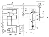
도 1에는 실질적으로 전기 제어 장치(220), 전기 모터(221), 정량 공급 펌프(222) 및 라인(4) 내부에 고압 유체를 형성하기 위한 증압기(21)를 포함하는 유압 유닛(2)을 구비한 유체 젯 절단 장치(1)가 도시되어 있다.1 shows a
체크 밸브(31) 및 제어 가능한 개폐 밸브(32)를 구비한 맥동 감쇠기(3)는, 한편으로는 개폐 가능한 압력 방출 밸브(61)에 연결되어 있고, 다른 한편으로는 절단 헤드(5)에 연결되어 있는 고압 라인(4)의 영역 내에 위치한다.The
상기 절단 헤드(5)는 고압 유체의 공급 영역 내에 스톱 밸브(54)를 구비하고, 그 다음에 노즐(51) 및 연마 재료(53)용 혼합 챔버(52)를 구비한다.The
유압 유닛(2)에 의해 상기 유체 라인(4) 내부의 압력이 변경되는 경우, 상기 스톱 밸브(54)를 폐쇄함으로써 상기 절단 헤드가 작동 정지될 수 있다.When the pressure inside the
도 2에는 고압 유체와 비교하여 더 낮은 압력의 유체를 생성하기 위한 수단(7)을 포함하는 것을 제외하고, 도 1과 동일한 유형의 장치가 도시되어 있다. 2 shows a device of the same type as in Fig. 1, except that it comprises means 7 for producing a lower pressure fluid as compared to a higher pressure fluid.
절단 헤드는 스톱 밸브(54)와 노즐(51) 사이에 저압 유체를 생성하기 위한 수단(7)의 스톱 밸브(71) 쪽으로 향하는 고압 라인의 분기 연결부를 포함하고, 이때 상기 압력 라인(41) 내부에는 고압 작동시 가급적 경우에 따른 펌프 장치(70) 쪽으로 향하는 연결부를 차단하는 체크 밸브(72)가 배치되어 있다. The cutting head includes a branch connection of a high pressure line towards the
Claims (6)
경우에 따라 적어도 서로 다른 2개의 압력에 의해 구동 가능한 유압 유닛(2), 밸브들(31, 32)을 구비한 고압 라인(4) 내부의 적어도 하나의 맥동 감쇠기(pulsation damper)(3) 및 노즐(51) 및 연마 재료(53)용 혼합 장치(52)를 구비한 절단 헤드(5)를 포함하는 상기 유체 젯- 또는 워터 젯 절단 장치에 있어서,
절단 헤드(5) 내 노즐(51) 쪽으로 향하는 유체의 공급 라인(4) 또는 고압 라인의 영역 내에 개폐 가능한 스톱 밸브(stop valve)(54), 소위 절단 밸브가 배치되어 있는 것을 특징으로 하는,
유체 젯- 또는 워터 젯 절단 장치.A fluid jet or water jet cutting apparatus (1) comprising:
At least one pulsation damper 3 in the high-pressure line 4 with the hydraulic unit 2, valves 31 and 32, which can be driven by at least two different pressures, (51) and a cutting head (5) having a mixing device (52) for the abrasive material (53), characterized in that the cutting head
Characterized in that a stop valve (54), a so-called cut valve, which can be opened or closed in the region of the supply line (4) or the high pressure line of the fluid toward the nozzle (51) in the cutting head (5)
A fluid jet or water jet cutting device.
상기 유압 유닛(2)은, 예를 들어 AT 512322 B1호 및 EP 3012453 A2호에 실질적으로 공지된 바와 같이 저압 측에 제어 가능한 또는 조절 가능한 유압 구동 장치(220), 다시 말해 정량 공급 펌프(222)용 전기 모터(221)를 포함하는 증압기를 포함하는 것을 특징으로 하는,
유체 젯- 또는 워터 젯 절단 장치.The method according to claim 1,
The hydraulic unit 2 comprises a controllable or adjustable hydraulic drive device 220, i. E. A metering feed pump 222, on the low pressure side, as is known, for example, from AT 512322 B1 and EP 3012453 A2, Characterized in that it comprises an intensifier comprising an electric motor (221)
A fluid jet or water jet cutting device.
상기 맥동 감쇠기는(들은)(3) 각각 한편으로는 체크 밸브(check valve)(31)에 의해, 그리고 다른 한편으로는 제어 가능한 개폐 밸브(32)에 의해 상기 고압 라인(4)에 연결되어 있는 것을 특징으로 하는,
유체 젯- 또는 워터 젯 절단 장치.3. The method according to claim 1 or 2,
The pulsation attenuator is connected to the high-pressure line 4 by a check valve 31 on the one hand and (3) a control valve 32 on the other hand by a controllable valve 32 ≪ / RTI >
A fluid jet or water jet cutting device.
상기 유체 고압 라인(4) 내에서 상기 절단 헤드(5) 앞에는 개폐 가능한 압력 방출 밸브(pressure relief valve)(6)가 배치되어 있는 것을 특징으로 하는,
유체 젯- 또는 워터 젯 절단 장치.4. The method according to any one of claims 1 to 3,
Characterized in that a pressure relief valve (6) capable of opening and closing is arranged in front of the cutting head (5) in the fluid high pressure line (4)
A fluid jet or water jet cutting device.
상기 유체 고압 라인(4) 내에서 상기 절단 헤드(5) 내 절단 밸브(54) 다음에서, 그러나 노즐(51) 앞에서 개폐 가능한 스톱 밸브(71)를 통해 유체는 펌프 장치에 의해 감소한 압력으로 유입될 수 있는 것을 특징으로 하는,
유체 젯- 또는 워터 젯 절단 장치.5. The method according to any one of claims 1 to 4,
The fluid is introduced into the fluid high pressure line 4 through the stop valve 71 in the cutting head 5, but after the stop valve 71, which is openable in front of the nozzle 51, Lt; RTI ID = 0.0 >
A fluid jet or water jet cutting device.
고압 유체와 비교하여 감소한 압력의 유체를 생성하기 위한 수단(7)은 적어도 하나의 펌프 장치(70) 및 스톱 밸브(71) 쪽으로 향하는 공급 라인(41) 내부의 체크 밸브(72)를 포함하는 것을 특징으로 하는,
유체 젯- 또는 워터 젯 절단 장치.
6. The method of claim 5,
The means 7 for producing a fluid of reduced pressure in comparison with the high pressure fluid comprises at least one pump device 70 and a check valve 72 inside the supply line 41 towards the stop valve 71 Features,
A fluid jet or water jet cutting device.
Applications Claiming Priority (2)
| Application Number | Priority Date | Filing Date | Title |
|---|---|---|---|
| ATA50162/2017A AT519687A1 (en) | 2017-03-01 | 2017-03-01 | Fluid jet or water jet cutter |
| ATA50162/2017 | 2017-03-01 |
Publications (1)
| Publication Number | Publication Date |
|---|---|
| KR20180100480A true KR20180100480A (en) | 2018-09-11 |
Family
ID=61132307
Family Applications (1)
| Application Number | Title | Priority Date | Filing Date |
|---|---|---|---|
| KR1020180020550A KR20180100480A (en) | 2017-03-01 | 2018-02-21 | Fluid jet- or water jet cutting device |
Country Status (4)
| Country | Link |
|---|---|
| EP (1) | EP3369527A1 (en) |
| KR (1) | KR20180100480A (en) |
| CN (1) | CN108527166A (en) |
| AT (1) | AT519687A1 (en) |
Families Citing this family (3)
| Publication number | Priority date | Publication date | Assignee | Title |
|---|---|---|---|---|
| CN109139575A (en) * | 2018-09-24 | 2019-01-04 | 佛山市元利精密机械有限公司 | A kind of Water Cutting equipment just dismounted |
| DE102018124978A1 (en) * | 2018-10-10 | 2020-04-16 | Alfred Kärcher SE & Co. KG | Apparatus and method for providing pressurized fluid to multiple consumers |
| DE102019208707A1 (en) * | 2019-06-14 | 2020-12-17 | Thyssenkrupp Ag | Device and method for providing pressurized medium for injection into a high pressure process |
Family Cites Families (10)
| Publication number | Priority date | Publication date | Assignee | Title |
|---|---|---|---|---|
| IT1073144B (en) * | 1976-10-28 | 1985-04-13 | Welko Ind Spa | HYDRAULIC EQUIPMENT FOR THE SUPPLY OF LIQUID AT TWO DIFFERENT PRESSURES TO A HYDRAULIC DEVICE |
| JPH0645119B2 (en) * | 1989-05-30 | 1994-06-15 | 川崎重工業株式会社 | Water jet processing equipment equipped with decompressor for high pressure water |
| AT9123U1 (en) * | 2006-02-22 | 2007-05-15 | Boehler Hochdrucktech Gmbh | EQUIPMENT FOR WATER JET OR ABRASIVE WATER JET CUTTING |
| JP5205481B2 (en) * | 2011-02-02 | 2013-06-05 | 株式会社スギノマシン | Abrasive water jet machine |
| AT512322B1 (en) * | 2011-12-30 | 2013-09-15 | Bhdt Gmbh | HYDRAULIC DRIVE FOR A PRESSURE TRANSLATOR |
| CN105297603A (en) * | 2014-07-04 | 2016-02-03 | 桂林电子科技大学 | Water jet cutting device for repairing craters in airport runway |
| AT515937B1 (en) | 2014-10-20 | 2016-01-15 | Bhdt Gmbh | Hydraulic drive for a pressure intensifier |
| AT515943B1 (en) * | 2014-10-20 | 2016-01-15 | Perndorfer Andreas | Method for operating a plant for water jet cutting and installation for water jet cutting |
| AT516738B1 (en) * | 2015-02-23 | 2016-08-15 | Reinhard Ing Gruber | Method and device for operating a hydraulic high pressure system |
| DE102015104245B3 (en) | 2015-03-20 | 2016-07-21 | Thyssenkrupp Ag | Apparatus and method for cutting a material to be cut by means of a fluid |
-
2017
- 2017-03-01 AT ATA50162/2017A patent/AT519687A1/en unknown
-
2018
- 2018-02-01 EP EP18154700.1A patent/EP3369527A1/en not_active Withdrawn
- 2018-02-21 KR KR1020180020550A patent/KR20180100480A/en not_active Application Discontinuation
- 2018-02-28 CN CN201810165650.XA patent/CN108527166A/en active Pending
Also Published As
| Publication number | Publication date |
|---|---|
| AT519687A1 (en) | 2018-09-15 |
| EP3369527A1 (en) | 2018-09-05 |
| CN108527166A (en) | 2018-09-14 |
Similar Documents
| Publication | Publication Date | Title |
|---|---|---|
| KR20180100480A (en) | Fluid jet- or water jet cutting device | |
| US6755725B2 (en) | Method and apparatus for fluid jet formation | |
| EP1825958B1 (en) | Device for shearing equipment with a water jet or abrasive water jet | |
| US4707952A (en) | Liquid/abrasive jet cutting apparatus | |
| CN104175230B (en) | Suspension grinding material water jet cutting equipment | |
| TW200730731A (en) | Wide range pressure control using turbo pump | |
| CN107405754B (en) | Device and method for being cut article to be cut by means of fluid | |
| CN114630715B (en) | Two-fluid nozzle spray device | |
| EP2318190B1 (en) | Mixing discharge device | |
| CA2444951A1 (en) | Abrasive fluid jet system | |
| AT515943B1 (en) | Method for operating a plant for water jet cutting and installation for water jet cutting | |
| EP1554747A2 (en) | Plasma system and method for anistropically etching structures into a substrate | |
| DE102014005533B3 (en) | Blowing station with compressed-air-operated form-locking device and method for holding together a multi-part blow mold | |
| DE1515240B2 (en) | Process for processing materials by means of a beam of charged particles and apparatus for carrying out this process | |
| RU2576951C2 (en) | Gas evacuation method for disconnected section of gas pipeline | |
| EP0780184A1 (en) | Device for longitudinal and transversely dividing cold or hot steel slaps | |
| EP3235454A1 (en) | Device and system for dispensing shock waves | |
| WO2020095291A1 (en) | Irrigation device | |
| JPH033799A (en) | Water jetting device equipped with pressure reduction device of high pressure water | |
| CN108026711B (en) | Underwater slotting apparatus and pumping apparatus | |
| EP3254807A1 (en) | Method and device for cleaning with a blasting device | |
| WO2023217950A1 (en) | Hydraulic switch and drill hammer | |
| KR20090026316A (en) | Component-feed nozzle with depressurization | |
| JP3855245B2 (en) | Wet peening method and apparatus | |
| JP2001300849A (en) | Injection opening-closing valve of air blast machine |
Legal Events
| Date | Code | Title | Description |
|---|---|---|---|
| A201 | Request for examination | ||
| E902 | Notification of reason for refusal | ||
| E601 | Decision to refuse application |