KR20180098792A - Strechable conductive film, manufacturing method of the same and uses thereof - Google Patents
Strechable conductive film, manufacturing method of the same and uses thereof Download PDFInfo
- Publication number
- KR20180098792A KR20180098792A KR1020170025363A KR20170025363A KR20180098792A KR 20180098792 A KR20180098792 A KR 20180098792A KR 1020170025363 A KR1020170025363 A KR 1020170025363A KR 20170025363 A KR20170025363 A KR 20170025363A KR 20180098792 A KR20180098792 A KR 20180098792A
- Authority
- KR
- South Korea
- Prior art keywords
- thin film
- stretchable
- conductive thin
- polymer
- xylene
- Prior art date
- Legal status (The legal status is an assumption and is not a legal conclusion. Google has not performed a legal analysis and makes no representation as to the accuracy of the status listed.)
- Withdrawn
Links
Images


Classifications
-
- H—ELECTRICITY
- H01—ELECTRIC ELEMENTS
- H01B—CABLES; CONDUCTORS; INSULATORS; SELECTION OF MATERIALS FOR THEIR CONDUCTIVE, INSULATING OR DIELECTRIC PROPERTIES
- H01B5/00—Non-insulated conductors or conductive bodies characterised by their form
- H01B5/16—Non-insulated conductors or conductive bodies characterised by their form comprising conductive material in insulating or poorly conductive material, e.g. conductive rubber
-
- B—PERFORMING OPERATIONS; TRANSPORTING
- B05—SPRAYING OR ATOMISING IN GENERAL; APPLYING FLUENT MATERIALS TO SURFACES, IN GENERAL
- B05D—PROCESSES FOR APPLYING FLUENT MATERIALS TO SURFACES, IN GENERAL
- B05D1/00—Processes for applying liquids or other fluent materials
- B05D1/002—Processes for applying liquids or other fluent materials the substrate being rotated
- B05D1/005—Spin coating
-
- C—CHEMISTRY; METALLURGY
- C09—DYES; PAINTS; POLISHES; NATURAL RESINS; ADHESIVES; COMPOSITIONS NOT OTHERWISE PROVIDED FOR; APPLICATIONS OF MATERIALS NOT OTHERWISE PROVIDED FOR
- C09D—COATING COMPOSITIONS, e.g. PAINTS, VARNISHES OR LACQUERS; FILLING PASTES; CHEMICAL PAINT OR INK REMOVERS; INKS; CORRECTING FLUIDS; WOODSTAINS; PASTES OR SOLIDS FOR COLOURING OR PRINTING; USE OF MATERIALS THEREFOR
- C09D125/00—Coating compositions based on homopolymers or copolymers of compounds having one or more unsaturated aliphatic radicals, each having only one carbon-to-carbon double bond, and at least one being terminated by an aromatic carbocyclic ring; Coating compositions based on derivatives of such polymers
- C09D125/02—Homopolymers or copolymers of hydrocarbons
- C09D125/04—Homopolymers or copolymers of styrene
- C09D125/08—Copolymers of styrene
- C09D125/10—Copolymers of styrene with conjugated dienes
-
- C—CHEMISTRY; METALLURGY
- C09—DYES; PAINTS; POLISHES; NATURAL RESINS; ADHESIVES; COMPOSITIONS NOT OTHERWISE PROVIDED FOR; APPLICATIONS OF MATERIALS NOT OTHERWISE PROVIDED FOR
- C09D—COATING COMPOSITIONS, e.g. PAINTS, VARNISHES OR LACQUERS; FILLING PASTES; CHEMICAL PAINT OR INK REMOVERS; INKS; CORRECTING FLUIDS; WOODSTAINS; PASTES OR SOLIDS FOR COLOURING OR PRINTING; USE OF MATERIALS THEREFOR
- C09D175/00—Coating compositions based on polyureas or polyurethanes; Coating compositions based on derivatives of such polymers
- C09D175/04—Polyurethanes
-
- H—ELECTRICITY
- H01—ELECTRIC ELEMENTS
- H01B—CABLES; CONDUCTORS; INSULATORS; SELECTION OF MATERIALS FOR THEIR CONDUCTIVE, INSULATING OR DIELECTRIC PROPERTIES
- H01B1/00—Conductors or conductive bodies characterised by the conductive materials; Selection of materials as conductors
- H01B1/02—Conductors or conductive bodies characterised by the conductive materials; Selection of materials as conductors mainly consisting of metals or alloys
-
- H—ELECTRICITY
- H01—ELECTRIC ELEMENTS
- H01B—CABLES; CONDUCTORS; INSULATORS; SELECTION OF MATERIALS FOR THEIR CONDUCTIVE, INSULATING OR DIELECTRIC PROPERTIES
- H01B13/00—Apparatus or processes specially adapted for manufacturing conductors or cables
- H01B13/0026—Apparatus for manufacturing conducting or semi-conducting layers, e.g. deposition of metal
-
- H—ELECTRICITY
- H01—ELECTRIC ELEMENTS
- H01B—CABLES; CONDUCTORS; INSULATORS; SELECTION OF MATERIALS FOR THEIR CONDUCTIVE, INSULATING OR DIELECTRIC PROPERTIES
- H01B7/00—Insulated conductors or cables characterised by their form
- H01B7/04—Flexible cables, conductors, or cords, e.g. trailing cables
-
- H01L31/022425—
-
- H01L31/03926—
-
- H—ELECTRICITY
- H10—SEMICONDUCTOR DEVICES; ELECTRIC SOLID-STATE DEVICES NOT OTHERWISE PROVIDED FOR
- H10F—INORGANIC SEMICONDUCTOR DEVICES SENSITIVE TO INFRARED RADIATION, LIGHT, ELECTROMAGNETIC RADIATION OF SHORTER WAVELENGTH OR CORPUSCULAR RADIATION
- H10F77/00—Constructional details of devices covered by this subclass
- H10F77/10—Semiconductor bodies
- H10F77/16—Material structures, e.g. crystalline structures, film structures or crystal plane orientations
- H10F77/169—Thin semiconductor films on metallic or insulating substrates
- H10F77/1698—Thin semiconductor films on metallic or insulating substrates the metallic or insulating substrates being flexible
-
- H—ELECTRICITY
- H10—SEMICONDUCTOR DEVICES; ELECTRIC SOLID-STATE DEVICES NOT OTHERWISE PROVIDED FOR
- H10F—INORGANIC SEMICONDUCTOR DEVICES SENSITIVE TO INFRARED RADIATION, LIGHT, ELECTROMAGNETIC RADIATION OF SHORTER WAVELENGTH OR CORPUSCULAR RADIATION
- H10F77/00—Constructional details of devices covered by this subclass
- H10F77/20—Electrodes
- H10F77/206—Electrodes for devices having potential barriers
- H10F77/211—Electrodes for devices having potential barriers for photovoltaic cells
-
- Y—GENERAL TAGGING OF NEW TECHNOLOGICAL DEVELOPMENTS; GENERAL TAGGING OF CROSS-SECTIONAL TECHNOLOGIES SPANNING OVER SEVERAL SECTIONS OF THE IPC; TECHNICAL SUBJECTS COVERED BY FORMER USPC CROSS-REFERENCE ART COLLECTIONS [XRACs] AND DIGESTS
- Y02—TECHNOLOGIES OR APPLICATIONS FOR MITIGATION OR ADAPTATION AGAINST CLIMATE CHANGE
- Y02E—REDUCTION OF GREENHOUSE GAS [GHG] EMISSIONS, RELATED TO ENERGY GENERATION, TRANSMISSION OR DISTRIBUTION
- Y02E10/00—Energy generation through renewable energy sources
- Y02E10/50—Photovoltaic [PV] energy
Landscapes
- Chemical & Material Sciences (AREA)
- Engineering & Computer Science (AREA)
- Life Sciences & Earth Sciences (AREA)
- Materials Engineering (AREA)
- Wood Science & Technology (AREA)
- Organic Chemistry (AREA)
- Manufacturing & Machinery (AREA)
- Sustainable Development (AREA)
- Sustainable Energy (AREA)
- Conductive Materials (AREA)
- Non-Insulated Conductors (AREA)
Abstract
본 발명은 전기화학소자 및 이의 제조방법에 관한 것으로, 본 발명에 따른 전기화학소자는, 기존의 액체 전해질의 화재 위험, 전해질 누출 및 외기나 습기에 노출 시 폭발 등이 안전성 문제를 해결하였고, 비표면적이 큰 탄소재를 첨가하여 소자의 효율을 극대화시켰고, 음극 및 양극에 폴리머 첨가제를 혼합하여 플렉서블(flexible)한 형태를 유지하여 다양한 분야에 적용할 수 있다. 또한, 열간 압착을 통해 원스텝(one step) 공정으로 간단하게 제조할 수 있어, 공정 비용 내지 시간을 현저히 줄일 수 있다.The present invention relates to an electrochemical device and a method for manufacturing the electrochemical device. The electrochemical device according to the present invention solves the safety problem of existing liquid electrolytes, such as fire risk, electrolyte leakage, and explosion upon exposure to outside air or moisture, By adding a carbon material with a large surface area, the efficiency of the device is maximized, and the polymer additive is mixed with the negative electrode and the positive electrode, so that the flexible material can be applied to various fields. In addition, it can be easily manufactured by a one-step process through hot pressing, and the process cost and time can be remarkably reduced.
Description
본 발명은 신축 가능한 전도성 박막, 이의 제조방법, 이를 포함하는 신축성 전극 및 상기 신축성 전극을 포함하는 플렉서블 또는 웨어러블 소자에 관한 것이다.
The present invention relates to a stretchable conductive thin film, a method of manufacturing the same, a stretchable electrode including the same, and a flexible or wearable device including the stretchable electrode.
반도체의 고집적화에 따라서 박막의 두께가 점점 얇아지고 대면적화가 되어 좀 더 안정적이고 균일한 무결점 박막을 형성 시킬 방법이 필요하게 되었다.As the semiconductor is highly integrated, the thickness of the thin film becomes thinner and larger, and a method of forming a more stable and homogeneous defect free thin film is needed.
그 대안 중 하나로써, 유기금속화합물을 사용하는 CVD(Chemical Vapor Deposition)/ALD(Atomic Layer Deposition) 증착 공정이 있다.One of the alternatives is CVD (Chemical Vapor Deposition) / ALD (Atomic Layer Deposition) deposition using an organometallic compound.
CVD/ALD 공정은, 사용되는 유기금속화합물은 반도체용 프리커서 또는 CVD/ALD 케미칼 등으로 불리는데, 박막형성을 목적으로 하는 금속에 유기 리간드를 붙여 하나의 화합물로 만드는 것이며, 특정 조건에서 상변화를 하고, 웨이퍼 표면에서 유기 리간드를 분해시켜 순수 금속막이나 산화 금속막, 질화 금속막 등을 선택적으로 형성시킬 수 있다. 또한, 박막을 제조할 때, 공간 내에서 기체의 특성을 이용하여 균일한 막을 형성할 수 있고, 투입량을 조절하여 막 두께를 조절할 수 있기 때문에, 초미세 박막의 형성이 가능하다는 장점이 있다.In the CVD / ALD process, the organometallic compound used is called a precursor for a semiconductor or a CVD / ALD chemical. In this process, an organic ligand is added to a metal for forming a thin film to form a single compound. And a pure metal film, a metal oxide film, a metal nitride film, and the like can be selectively formed by decomposing the organic ligand on the surface of the wafer. In addition, when a thin film is manufactured, a uniform film can be formed using the characteristics of gas in the space, and the film thickness can be controlled by controlling the amount of the introduced gas, so that an ultrafine thin film can be formed.
그러나, 일반적으로 많이 사용되는 금속 전극은 높은 전기 전도성을 가지고 있지만 유연성과 신축성이 매우 낮다. 반대로, 고분자나 탄성체와 같이 유연한 기질의 경우에는 높은 유연성을 가지고 있으나 전기 전도성이 매우 낮은 단점이 있다.However, generally used metal electrodes have high electrical conductivity, but have very low flexibility and stretchability. On the contrary, a flexible substrate such as a polymer or an elastomer has a high flexibility, but has a drawback in that the electric conductivity is very low.
따라서, 유연성과 신축성을 가짐과 동시에 우수한 전기 전도성을 갖는 박막을 개발해야 할 필요성이 있다.
Therefore, there is a need to develop a thin film having flexibility and stretchability and having excellent electrical conductivity.
본 발명은 신축 가능한 전도성 박막, 이의 제조방법 및 이의 용도에 관한 것으로, 유연성과 신축성을 가짐과 동시에 우수한 전기 전도성을 갖는 박막을 제공하고자 한다.
The present invention relates to a stretchable conductive thin film, a method for producing the thin film, and a use thereof, and is intended to provide a thin film having flexibility and stretchability and having excellent electrical conductivity.
본 발명은 신축 가능한 전도성 박막, 이의 제조방법 및 이의 용도에 관한 것으로, 상기 신축 가능한 전도성 박막의 하나의 예로서,The present invention relates to a stretchable conductive thin film, a method of manufacturing the same, and a use thereof, and as one example of the stretchable conductive thin film,
신축성 고분자 박막; 및Stretch polymer thin film; And
상기 신축성 고분자 박막에 화학적으로 결합된 금속 입자를 포함하며,And metal particles chemically bonded to the stretch polymer thin film,
100% 신장 후, 면 저항은 60x104 Ω/sq 이하인 신축 가능한 전도성 박막을 제공할 수 있다.
After 100% elongation, the sheet resistance can provide a stretchable conductive thin film of 60 x 10 4 ? / Sq or less.
또한, 상기 신축 가능한 전도성 박막의 제조방법의 하나의 예로서,As an example of the method of manufacturing the stretchable conductive thin film,
자일렌 및 신축성 고분자를 혼합한 용액을 스핀코팅 방법을 통해 박막으로 제조하는 단계; 및Preparing a solution of xylene and a stretch polymer in a thin film through a spin coating process; And
상기 박막을 금속 전구체 용액에 침지하고 환원제를 이용하여 금속을 환원시키는 단계를 포함하는 신축 가능한 전도성 박막의 제조방법을 제공할 수 있다.
And immersing the thin film in a metal precursor solution and reducing the metal by using a reducing agent.
또한, 본 발명은 상기 신축 가능한 전도성 박막을 포함하는 신축성 전극을 제공할 수 있다.
In addition, the present invention can provide an elastic electrode comprising the stretchable conductive thin film.
또한, 본 발명은 상기 신축성 전극을 포함하는 플렉서블 또는 웨어러블 소자를 제공할 수 있다.
In addition, the present invention can provide a flexible or wearable element including the elastic electrode.
본 발명에 따른 신축 가능한 전도성 박막은 신축성 고분자를 자일렌에 용해하고 스핀코팅하여 박막을 제조하고, 상기 박막을 금속 전구체 용액에 침지하고 금속을 환원시키는 간단한 방법으로 제조되며, 이렇게 제조된 신축 가능한 전도성 박막은 신축성이 우수하여 신장 후에도 우수한 전기 전도성을 유지할 수 있다.
The stretchable conductive thin film according to the present invention is manufactured by a simple method in which a thin film is prepared by dissolving a stretchable polymer in xylene and spin-coating the thin film, dipping the thin film in a metal precursor solution and reducing the metal, The thin film is excellent in stretchability and can maintain good electrical conductivity even after elongation.
도 1은 스핀 코터의 사진이다.
도 2는 면 저항 측정기의 사진 및 probe의 종류를 나타낸 것이다.
도 3은 다른 종류의 용매에 SEBS를 용해했을 때의 사진이다.
도 4는 신축 가능한 전도성 박막의 투명도 확인 실험 결과이다.
도 5 내지 7은 실시예 및 비교예에 따른 신축 가능한 전도성 박막의 두께에 따른 면 저항을 측정한 결과이다.
도 8은 실시예 및 비교예에 따른 신축 가능한 전도성 박막의 100 신장 후 면 저항 측정 결과이다.1 is a photograph of a spin coater.
2 shows a photograph of the surface resistance meter and the kind of the probe.
Fig. 3 is a photograph of the case where SEBS is dissolved in another kind of solvent.
Fig. 4 shows the results of confirming transparency of a stretchable conductive thin film.
FIGS. 5 to 7 are the results of measurement of the surface resistance according to the thickness of the stretchable conductive thin film according to the embodiment and the comparative example.
FIG. 8 shows the results of measurement of surface resistance after 100 stretches of stretchable conductive thin films according to Examples and Comparative Examples.
본 발명은 다양한 변경을 가할 수 있고 여러 가지 실시예를 가질 수 있는 바, 특정 실시예들을 도면에 예시하고 상세한 설명에 상세하게 설명하고자 한다.While the invention is susceptible to various modifications and alternative forms, specific embodiments thereof are shown by way of example in the drawings and will herein be described in detail.
그러나, 이는 본 발명을 특정한 실시 형태에 대해 한정하려는 것이 아니며, 본 발명의 사상 및 기술 범위에 포함되는 모든 변경, 균등물 내지 대체물을 포함하는 것으로 이해되어야 한다.It should be understood, however, that the invention is not intended to be limited to the particular embodiments, but includes all modifications, equivalents, and alternatives falling within the spirit and scope of the invention.
본 발명에서, "포함한다" 또는 "가지다" 등의 용어는 명세서상에 기재된 특징, 숫자, 단계, 동작, 구성요소, 부품 또는 이들을 조합한 것이 존재함을 지정하려는 것이지, 하나 또는 그 이상의 다른 특징들이나 숫자, 단계, 동작, 구성요소, 부품 또는 이들을 조합한 것들의 존재 또는 부가 가능성을 미리 배제하지 않는 것으로 이해되어야 한다.In the present invention, the terms "comprising" or "having ", and the like, specify that the presence of a feature, a number, a step, an operation, an element, a component, But do not preclude the presence or addition of one or more other features, integers, steps, operations, elements, components, or combinations thereof.
또한, 본 발명에서 첨부된 도면은 설명의 편의를 위하여 확대 또는 축소하여 도시된 것으로 이해되어야 한다.
It is to be understood that both the foregoing general description and the following detailed description are exemplary and explanatory and are intended to provide further explanation of the invention as claimed.
기존의 전도성 박막 제조시 일반적으로 많이 사용되는 금속 전극은 높은 전기 전도성을 가지고 있지만 유연성과 신축성이 매우 낮다. 반대로, 고분자나 탄성체와 같이 유연한 기질의 경우에는 높은 유연성을 가지고 있으나 전기 전도성이 매우 낮은 단점이 있었다.Metal electrodes, which are commonly used in the production of conventional conductive thin films, have high electrical conductivity, but have very low flexibility and stretchability. On the contrary, a flexible substrate such as a polymer or an elastomer has a high flexibility, but has a drawback in that the electric conductivity is very low.
따라서, 유연성과 신축성을 가짐과 동시에 우수한 전기 전도성을 갖는 박막을 개발해야 할 필요성이 있었다.Accordingly, there has been a need to develop a thin film having flexibility and stretchability and having excellent electrical conductivity.
이에, 본 발명에서는 신축성을 가짐과 동시에 우수한 전기 전도성을 갖는 신축 가능한 전도성 박막 및 이의 제조방법을 제공하고자 한다.Accordingly, the present invention provides a stretchable conductive thin film having stretchability and excellent electrical conductivity, and a method for producing the same.
구체적으로, 본 발명에 따른 신축 가능한 전도성 박막은 신축성 고분자를 자일렌에 용해하고 스핀코팅하여 박막을 제조하고, 상기 박막을 금속 전구체 용액에 침지하고 금속을 환원시키는 간단한 방법으로 제조되며, 이렇게 제조된 신축 가능한 전도성 박막은 신축성이 우수하여 신장 후에도 우수한 전기 전도성을 유지할 수 있다.Specifically, the stretchable conductive thin film according to the present invention is manufactured by a simple method of dissolving a stretchable polymer in xylene and spin coating to prepare a thin film, immersing the thin film in a metal precursor solution and reducing the metal, The stretchable conductive thin film is excellent in stretchability and can maintain excellent electrical conductivity even after stretching.
이렇게 신축성을 가짐과 동시에 우수한 전기 전도성을 갖는 본 발명에 따른 신축 가능한 전도성 박막은 플렉서블 디스플레이, 스마트 의류, 착용형 치료센서 시스템 등 다양한 분야에 활용이 가능하기 때문에 넓은 산업 분야에서의 적용 및 발전을 기대할 수 있다. 이와 더불어, 본 발명에 따른 신축 가능한 전도성 박막은 바이오, 환경 등을 융합한 복합 기술로의 확대 가능성이 무한하다.
The stretchable and conductive thin film according to the present invention having elasticity and excellent electrical conductivity can be applied to various fields such as flexible display, smart clothing, and wearable treatment sensor system, so that application and development in a wide industrial field can be expected . In addition, the expandable and contractible conductive thin film according to the present invention has an infinite possibility of expanding into a hybrid technology in which bio, environment and the like are fused.
이하, 본 발명에 대하여 구체적으로 설명하기로 한다.Hereinafter, the present invention will be described in detail.
본 발명은 신축 가능한 전도성 박막, 이의 제조방법 및 이의 용도에 관한 것으로, 상기 신축 가능한 전도성 박막의 하나의 예로서,The present invention relates to a stretchable conductive thin film, a method of manufacturing the same, and a use thereof, and as one example of the stretchable conductive thin film,
신축성 고분자 박막; 및Stretch polymer thin film; And
상기 신축성 고분자 박막에 화학적으로 결합된 금속 입자를 포함하며,And metal particles chemically bonded to the stretch polymer thin film,
100% 신장 후, 면 저항은 60x104 Ω/sq 이하인 신축 가능한 전도성 박막을 제공할 수 있다.After 100% elongation, the sheet resistance can provide a stretchable conductive thin film of 60 x 10 4 ? / Sq or less.
상기 신축성 고분자는 폴리부타디엔(PB), 폴리(스티렌-부타디엔)(PS-b-PB, PS-co-PB), 폴리(스티렌-부타디엔-스티렌)(PS-b-PB-b-PS)(SBS), 폴리(스티렌-에틸렌-부틸렌-스티렌)(SEBS), 폴리우레탄(PU) 및 폴리이소프렌 중 1 종 이상을 포함할 수 있다.(PS-b-PB-b-PS) (polybutadiene) SBS), poly (styrene-ethylene-butylene-styrene) (SEBS), polyurethane (PU) and polyisoprene.
상기 신축성 고분자는 SEBS일 수 있다. The stretch polymer may be SEBS.
SEBS는 SBS가 부타디엔의 C=C 결합이 제거되어 에틸렌과 부틸렌 중간 블록을 생성하는 촉매 수소화 반응(Hydrogenation)을 거쳐 만들어진다. SEBS의 구조에 의한 이점으로는 스티렌의 조성비에 따른 특성조절이 자유로우며, 빛에 강한 내후성을 가진다는 것이다.SEBS is produced by catalytic hydrogenation in which SBS removes the C = C bond of butadiene to form ethylene and butylene intermediate blocks. The advantage of the structure of SEBS is that it is free to control the characteristics according to the composition ratio of styrene and has a weather-resistant ability to light.
SEBS는 SBS를 베이스로 한 열가소성 탄성체로서, 사출, 압출 및 blow molding이 가능하며, 엔지니어링 플라스틱(Nylon, PBT, PC, ABS, PMMA, PC, PS 등)과 접착이 가능한 제품도 있다. 또한, 유연성이 뛰어나고 탄성 회복성, 내후성 및 내열성이 우수하며 접착력이 탁월하다. 또한, 사출성형, 압출성형 등 플라스틱과 같이 성형가공 할 수 있는 자연 친화적이고 친환경적인 충진재이다. 또한, SEBS는 가황고무와 PVC의 대체소재로서, 자동차, 건축자재, 가전제품 등 다양한 분야에서 쓰이고 있으며, 특히 가전제품의 고급화와 함께 안정성을 향상시키는 소재로 기존에 있는 소재의 대체제로 활발하게 사용되고 있는 고분자 재료이다.SEBS is a thermoplastic elastomer based on SBS. It can be used for injection, extrusion and blow molding. It can be bonded to engineering plastics (Nylon, PBT, PC, ABS, PMMA, PC, PS etc.). In addition, it is excellent in flexibility, excellent in elastic recovery property, weather resistance and heat resistance, and excellent in adhesion. In addition, it is a nature-friendly and environment-friendly filling material that can be molded and processed like plastic such as injection molding and extrusion molding. SEBS is a substitute for vulcanized rubber and PVC. It is used in various fields such as automobiles, building materials, home appliances, etc. Especially, it is used as a substitute for existing materials as a material to improve the stability with the upgrading of household appliances Lt; / RTI >
상기 금속 입자는 금, 은, 구리 및 백금 중 1 종 이상을 포함할 수 있다. 금속 입자는 구체적으로, 상기 금속 입자는 은을 포함할 수 있다.The metal particles may include at least one of gold, silver, copper, and platinum. Specifically, the metal particles may include silver.
상기 금속 입자는 신축 가능한 전도성 박막 전체 100 중량부를 기준으로 20 내지 80 중량부를 포함할 수 있으며, 예를 들어, 20 내지 70 중량부, 20 내지 60 중량부 또는 20 내지 50 중량부를 포함할 수 있다.The metal particles may include 20 to 80 parts by weight, for example, 20 to 70 parts by weight, 20 to 60 parts by weight, or 20 to 50 parts by weight based on 100 parts by weight of the entire stretchable conductive thin film.
상기 금속 입자의 평균 직경은 5 내지 100 nm 범위일 수 있다. 예를 들어, 상기 금속 입자의 평균 직경은 5 내지 90 nm, 5 내지 80 nm, 5 내지 70 nm, 10 내지 60 nm 또는 10 내지 50 nm 범위일 수 있다.The mean diameter of the metal particles may range from 5 to 100 nm. For example, the average diameter of the metal particles may range from 5 to 90 nm, from 5 to 80 nm, from 5 to 70 nm, from 10 to 60 nm, or from 10 to 50 nm.
본 발명에 따른 신축 가능한 전도성 박막은 상기와 같은 금속 입자를 포함함으로써, 신축성을 가짐과 동시에 우수한 전기 전도성을 구현할 수 있다.The expandable and contractible conductive thin film according to the present invention includes the metal particles as described above, so that the conductive thin film has elasticity and excellent electrical conductivity.
구체적으로, 본 발명에 따른 신축 가능한 전도성 박막이 신장되는 경우에도, 그 위의 금속 입자들은 나노미터 단위의 크기를 가지는 나노입자이므로 깨지거나 절단되지 않으며, 또한 퍼콜레이션 네트워크에 의하여 전기적인 경로를 유지할 수 있으므로 전기 전도성을 유지할 수 있다.In particular, even when the stretchable conductive thin film according to the present invention is stretched, the metal particles thereon are not broken or cut off because they are nanoparticles having a size of nanometer unit, and the electrical path is maintained by the percolation network So that the electric conductivity can be maintained.
본 발명에 따른 신축 가능한 전도성 박막의 평균 두께는 30 내지 100 ㎛ 범위일 수 있다. 예를 들어, 신축 가능한 전도성 박막의 평균 두께는 35 내지 100 ㎛, 40 내지 100 ㎛, 50 내지 100 ㎛, 60 내지 100 ㎛ 또는 60 내지 80 ㎛ 범위일 수 있다. 신축 가능한 전도성 박막의 평균 두께가 상기 범위를 벗어날 경우, 우수한 신축성과 전기 전도성을 동시에 만족하기 어렵다.
The average thickness of the stretchable conductive thin film according to the present invention may range from 30 to 100 mu m. For example, the average thickness of the stretchable conductive thin film may range from 35 to 100 mu m, from 40 to 100 mu m, from 50 to 100 mu m, from 60 to 100 mu m, or from 60 to 80 mu m. When the average thickness of the stretchable conductive thin film is out of the above range, excellent stretchability and electric conductivity are hardly satisfied at the same time.
본 발명은 상술한 신축 가능한 전도성 박막의 제조방법을 제공할 수 있다. 상기 신축 가능한 전도성 박막의 제조방법의 하나의 예로서,The present invention can provide a method of manufacturing the above-described stretchable conductive thin film. As one example of the method of manufacturing the stretchable conductive thin film,
자일렌 및 신축성 고분자를 혼합한 용액을 스핀코팅 방법을 통해 박막으로 제조하는 단계; 및Preparing a solution of xylene and a stretch polymer in a thin film through a spin coating process; And
상기 박막을 금속 전구체 용액에 침지하고 환원제를 이용하여 금속을 환원시키는 단계를 포함하는 신축 가능한 전도성 박막의 제조방법을 제공할 수 있다.And immersing the thin film in a metal precursor solution and reducing the metal by using a reducing agent.
구체적으로, 상기 자일렌은 메타 자일렌(m-Xylene)일 수 있다. 본 발명은, 신축성 고분자를 용해할 용매로서, 자일렌을 사용함으로써, 이를 이용하여 제조된 신축 가능한 전도성 박막의 신장 후 전기 전도성 저하를 최소화 하였다.Specifically, the xylene may be meta xylene (m-xylene). The present invention minimizes degradation of electrical conductivity after elongation of a stretchable conductive thin film produced by using xylene as a solvent for dissolving a stretchable polymer.
상기 자일렌 및 신축성 고분자를 혼합한 용액 100 중량부를 기준으로,Based on 100 parts by weight of a solution prepared by mixing the xylene and the stretchable polymer,
신축성 고분자는 25 내지 40 중량부를 포함할 수 있다.The stretchable polymer may include 25 to 40 parts by weight.
예를 들어, 상기 신축성 고분자는 자일렌 및 신축성 고분자를 혼합한 용액 100 중량부를 기준으로 25 내지 38 중량부, 28 내지 35 중량부 또는 30 내지 35 중량부 범위로 포함할 수 있다. 자일렌 용매에 상기 범위의 신축성 고분자를 용해함으로써, 최적의 용해도로 신축성 고분자를 용해할 수 있다. 구체적으로, 자일렌 용매에 상기 범위의 신축성 고분자를 용해함으로써, 박막 제조에 최적화된 점도를 구현할 수 있다.For example, the stretchable polymer may include 25 to 38 parts by weight, 28 to 35 parts by weight, or 30 to 35 parts by weight based on 100 parts by weight of the solution of the mixture of xylene and the stretchable polymer. By dissolving the stretchable polymer within the above range in the xylene solvent, the stretchable polymer can be dissolved with optimum solubility. Specifically, by dissolving the stretchable polymer within the above range in the xylene solvent, a viscosity optimized for thin film production can be realized.
상기 자일렌 및 신축성 고분자를 혼합한 용액을 스핀코팅 방법을 통해 박막으로 제조하는 단계에서, 스핀코팅은 500 내지 2500 RPM으로, 1 내지 60 초 동안 수행할 수 있다.In the step of preparing a solution prepared by mixing the xylene and the stretchable polymer through a spin coating method, the spin coating may be performed at 500 to 2500 rpm for 1 to 60 seconds.
예를 들어, 상기 스핀코팅의 조건을 조절하여, 신축 가능한 전도성 박막의 두께를 용이하게 조절할 있다. 구체적으로, 스핀코팅의 스핀 스피드가 느릴수록 스핀 시간이 짧을수록 신축 가능한 전도성 박막의 두께가 두꺼워지고, 스핀 속도가 빠를수록 스핀 시간이 길수록 신축 가능한 전도성 박막의 두께가 얇아진다.For example, the thickness of the stretchable conductive thin film can be easily controlled by adjusting the conditions of the spin coating. Specifically, as the spin speed of the spin coating decreases, the thickness of the conductive thin film becomes larger as the spin time becomes shorter, and as the spin speed increases, the thickness of the conductive thin film becomes smaller as the spin time becomes longer.
예를 들어, 상기 스핀 속도는 1000 내지 2500 RPM, 1500 내지 2300 RPM, 1800 내지 2200 RPM 범위일 수 있고, 스핀 시간은 10 내지 50 초, 25 내지 50 초 또는 35 내지 45초 범위일 수 있다.For example, the spin rate may be in the range of 1000 to 2500 RPM, 1500 to 2300 RPM, 1800 to 2200 RPM, and the spin time may be in the range of 10 to 50 seconds, 25 to 50 seconds, or 35 to 45 seconds.
경우에 따라서, 상기 스핀 공정은 스핀 속도 및 시간을 달리한 3단계로 나눠 진행할 수 있다.In some cases, the spinning process may be divided into three steps, which are different in spin speed and time.
예를 들어, 상기 스핀 공정은 800 내지 1200 RPM으로 1 내지 5 초 동안 수행하는 제1 단계, 1800 내지 2200 RPM으로 25 내지 35 초 동안 수행하는 제2 단계 및 600 내지 1000 RPM으로 4 내지 6 초 동안 수행하는 제3 단계로 이루어질 수 있다. 이때, 각각의 단계에 주입되는 자일렌 및 신축성 고분자를 혼합한 용액의 양을 달리하여 신축 가능한 전도성 박막의 두께를 미세하게 조절할 수 있다.For example, the spinning process may include a first step of performing 800 to 1200 RPM for 1 to 5 seconds, a second step of performing 25 to 35 seconds at 1800 to 2200 RPM, and a second step of 600 to 1000 RPM for 4 to 6 seconds And a third step of performing the second step. At this time, the thickness of the stretchable conductive thin film can be finely adjusted by varying the amount of the mixed solution of the xylene and the stretchable polymer injected in each step.
상기 박막을 금속 전구체 용액에 침지하고 환원제를 이용하여 금속을 환원시키는 단계에서,In the step of immersing the thin film in a metal precursor solution and reducing the metal by using a reducing agent,
상기 금속 전구체 용액은 AgTFA, AgNO3, AgCl, HAuCl4, CuCl2, PtCl2 및 PtCl4 중 1 종 이상을 포함하는 용액일 수 있다.It said metal precursor solution may be a solution containing AgTFA, AgNO 3, AgCl, HAuCl 4, CuCl 2, PtCl 2 , and PtCl least one of the four kinds.
이때, 상기 금속 전구체 용액을 구성하는 용매는 상기 금속 전구체를 용해시킬 수 있는 알려진 용매를 제한 없이 사용할 수 있다. 예를 들면, 금속 전구체 용액은 에탄올에 실버 트리플루오로아세테이트(silver trifluoroacetate, AgTFA)을 용해시킨 용액일 수 있다.At this time, the solvent constituting the metal precursor solution may be any known solvent capable of dissolving the metal precursor. For example, the metal precursor solution may be a solution in which silver trifluoroacetate (AgTFA) is dissolved in ethanol.
이때, 상기 금속 전구체 용액은, 금속 전구체 용액 100 중량부를 기준으로 금속 전구체 10 내지 20 중량부를 포함하는 용액일 수 있다.At this time, the metal precursor solution may be a solution containing 10 to 20 parts by weight of a metal precursor based on 100 parts by weight of the metal precursor solution.
상기 박막을 금속 전구체 용액에 침지하고 환원제를 이용하여 금속을 환원시키는 단계는 구체적으로, 제조된 박막을 금속 전구체 용액에 약 20 내지 40 분간 침지하고, 건조시킨 후, 환원제를 이용하여 금속을 환원시킬 수 있다.Specifically, the thin film is immersed in a metal precursor solution for about 20 to 40 minutes, dried, and then the metal is reduced using a reducing agent. The thin film is immersed in a metal precursor solution and the metal is reduced using a reducing agent. .
상기 환원제로서, 히드라진 화합물 및 붕수소나트륨 화합물 중 1 종 이상을 포함할 수 있다.As the reducing agent, at least one of a hydrazine compound and a sodium borohydride compound may be contained.
구체적으로, 상기 금속 전구체 용액에 침지 후 건조시킨 박막 주위에 하이드라진모노하이드레이트(Hydrazine monohydrate) 용액을 떨어뜨린 후, 박막에 흡수되게 하고, 가스를 이용하여 5분간 환원시키는 방법으로 신축 가능한 전도성 박막에 금속 입자를 환원시킬 수 있다.Specifically, a solution of hydrazine monohydrate is dropped around the thin film after dipping in the metal precursor solution, and the thin film is absorbed into the thin film, and the thin film is reduced for 5 minutes by using a gas. The particles can be reduced.
그런 다음, 환원된 박막은 증류수를 이용하여 세척함으로써 물리적으로 결합된 금속 입자를 제거할 수 있다.
The reduced thin film may then be washed with distilled water to remove the physically bound metal particles.
본 발명은 상술한 신축 가능한 전도성 박막을 포함하는 신축성 전극을 제공할 수 있다.The present invention can provide an elastic electrode comprising the stretchable conductive thin film described above.
최근 유연성과 신축성을 겸비한 전극 및 기판의 개발에 대한 요구가 증가하고, 고체상의 박막전지에 대한 관심이 크게 증가하고 있다. 그러나, 박막전지는 화학적으로 안정되지 않다는 문제점이 있었다.Recently, there is an increasing demand for the development of electrodes and substrates having both flexibility and stretchability, and interest in solid-state thin film batteries is increasing. However, there is a problem that the thin film battery is not chemically stable.
이에 대해, 본 발명에 따른 신축 가능한 전도성 박막을 포함하는 신축성 전극은 기존의 고체상 박막전지의 안정성 문제를 해소하고, 우수한 신축성, 유연성 및 전기 전도성을 가질 수 있다.
On the contrary, the elastic electrode including the expandable conductive thin film according to the present invention can solve the stability problem of the conventional solid state thin film battery, and can have excellent stretchability, flexibility, and electric conductivity.
본 발명은 상술한 신축성 전극을 포함하는 플렉서블 또는 웨어러블 소자를 제공할 수 있다.The present invention can provide a flexible or wearable element including the aforementioned elastic electrode.
최근 기술 분야의 흐름은 웨어러블 기술(wearable technology)를 이용한 웨어러블 소자(wearable device)의 개발로 이어지고 있다. 이는 초소형 부품과 초박막형의 휘어지는(flexible) 디스플레이, 스마트 센서, 저 전력 무선 통신 등의 기술이 일상생활에 접목되어 표현된다. 뿐만 아니라, 웨어러블 기술은 스마트 워치와 같은 착용 컴퓨터(wearable computer), 스마트 의류(smart clothes), 피부에 이식하는 임플란트 등으로 응용되어 개인용뿐만 아니라 산업, 의료, 군사 등 모든 분야에 활용할 수 있다.[0002] The recent trend in the technical field has led to the development of wearable devices using wearable technology. This is expressed by incorporating technologies such as ultra-small parts, ultra-thin flexible displays, smart sensors, and low-power wireless communications into everyday life. In addition, the wearable technology can be applied to wearable computers such as smart watches, smart clothes, implants to be implanted in the skin, etc., and can be applied to all fields such as industry, medical, and military as well as personal use.
이에 대해, 본 발명에 따른 신축성 전극을 포함하는 플렉서블 또는 웨어러블 소자는 유연성과 신축성을 겸비한 전극 및 기판의 개발 요구에 맞춰 기계적 변형에도 전기 전도성을 유지하여, 디스플레이, 태양전지, 인공 전자 피부 등에 응용이 가능하다.
On the other hand, the flexible or wearable element including the elastic electrode according to the present invention maintains electrical conductivity against mechanical deformation in accordance with the development needs of electrodes and substrates having flexibility and stretchability, and is applied to displays, solar cells, It is possible.
이하 본 발명에 따르는 실시예 등을 통해 본 발명을 보다 상세히 설명하나, 본 발명의 범위가 하기 제시된 실시예에 의해 제한되는 것은 아니다.
Hereinafter, the present invention will be described in more detail with reference to the following Examples. However, the scope of the present invention is not limited by the following Examples.
<실험 장치><Experimental Apparatus>
(1) 스핀 코터(1) Spin Coaters
하기 도 1과 같은 스핀 코터(spin coater)를 사용하였다.A spin coater as shown in Fig. 1 was used.
구체적으로, 스핀 코터는, 물체 위에 올린 액체 수지를 원심력에 의해 코팅하여 박막을 만들어주는 기기이다. 가운데에 물체가 회전하는 동안 밖으로 이탈하지 못하도록 물체를 잡아주는 진공튜브가 있다. 최대 8000RPM까지 회전시킬 수 있고, 1단계부터 3단계까지 단계별로 RPM을 다르게 조절할 수 있다.Specifically, the spin coater is a device that forms a thin film by coating a liquid resin placed on an object by a centrifugal force. There is a vacuum tube in the center that holds the object to prevent it from escaping while the object is rotating. The RPM can be rotated up to 8000 RPM, and the RPM can be adjusted step by step from
스핀코터는 마이크로미터 단위의 얇은 두께까지 제조가 가능하고, 재료낭비가 적으며, 높은 균일성과 재생력을 가져 많은 공정에서 사용된다. 반도체 웨이퍼(원판)나 디스플레이 연구 시 시료 등 화학 물질의 균일 코팅에 쓰이는 필수 장비로 사용되고 있다.The spin coater can be manufactured to a thickness as small as micrometers, has low material waste, has high uniformity and reproducibility, and is used in many processes. It is used as an essential equipment for uniform coating of chemicals such as semiconductor wafers and samples for display research.
(2) 면 저항 측정기(2) Surface resistance meter
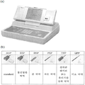
하기 도 2의 (a)와 같은 면 저항 측정기를 사용하였다.A surface resistance meter as shown in Fig. 2 (a) was used.
저항을 측정하기 위해 사용되는 측정기는 2-point-probe와 4-point-probe가 있다. 저항을 구하기 위해서는 2-point-probe로도 실험할 수 있지만 보통 4-point-probe를 사용한다. 2-point-probe는 양단간에 전압을 가하면 전류가 흐른다. 전체 저항 값을 알아야만 정확한 면 저항을 구할 수 있으나, 2-point-probe는 Rc 즉, 기판과 probe 간의 접촉 저항을 정확하게 알 수 없기 때문에 Rc, Rsp, Rb를 정확하게 구분할 수 없다. (Rp: probe 자체저항, Rc: 기판과 probe 사이의 접촉저항, Rsp: the spreding resistance)The measuring instruments used to measure the resistance are 2-point-probe and 4-point-probe. A 2-point-probe can be used to obtain the resistance, but usually a 4-point-probe is used. The 2-point-probe flows a current when a voltage is applied between both ends. Rc, Rsp, and Rb can not be accurately distinguished because the 2-point-probe can not accurately determine the contact resistance between Rc and substrate. (Rp: probe self-resistance, Rc: contact resistance between substrate and probe, Rsp: the spreding resistance)
특히, Rsp가 Rb보다 매우 크기 때문에 구하고자 하는 값을 정확하게 추출하기 어렵다.Especially, since Rsp is much larger than Rb, it is difficult to accurately extract the value to be obtained.
이를 보완하기 위해 4-point-probe를 사용한다.To compensate for this, use a 4-point probe.
박막에 따라 다양한 종류의 probe를 사용할 수 있다. 이는 도 2의 (b)에서 확인 가능하다.Various types of probes can be used depending on the film. This can be confirmed in FIG. 2 (b).
면 저항의 단위는 Ω/sq(Ω/□)이고, 4-point-probe는 4개의 탐침이 0.5 cm 간격으로 동일한 간격으로 되어있다.The unit of surface resistance is Ω / sq (Ω / □), and the 4-point probe has the same spacing of 4 probes spaced 0.5 cm apart.
구체적으로, 안쪽 두 탐침 사이의 전압과 바깥쪽 두 탐침 사이의 전류를 측정하여 박막의 면 저항을 측정한다.
Specifically, the surface resistance of the thin film is measured by measuring the voltage between the two inner probes and the current between the outer two probes.
제조예Manufacturing example : 신축 가능한 전도성 박막 제조: Conducting Thin Film Fabrication
(1) SEBS 용액 제조(1) Preparation of SEBS solution
용매 12g에 SEBS을 혼합하고, 2 내지 3일 동안 마그네틱 바를 넣은 교반기를 이용해 용해시켜, SEBS 용액을 제조하였다.SEBS was mixed with 12 g of the solvent and dissolved by using a stirrer equipped with a magnetic bar for 2 to 3 days to prepare an SEBS solution.
(2) 스핀코팅(2) Spin coating
스핀코터를 이용하여 제 1단계는 1000 RPM으로 3초, 제 2단계는 2000 RPM으로 30초, 제 3단계는 800 RPM으로 5초 동안 맞추고, 상기 SEBS 용액으로 박막을 만든 후 웨이퍼 위에서 자연건조 시켰다.Using a spin coater, the first stage was set at 1000 RPM for 3 seconds, the second stage was set at 2000 RPM for 30 seconds, the third stage was set at 800 RPM for 5 seconds, the thin film was formed with the SEBS solution, and then naturally dried on the wafer .
(3) 은 입자 흡착 및 환원(3) is a particle adsorption and reduction
에탄올에 AgTFA를 15wt%로 포함하는 용액에 상기 제조된 박막을 30분간 침지한 후 건조하였다. 그런 다음, 건조시킨 박막 주위에 하이드라진 모노하이드레이트(99.0%) 용액을 떨어뜨린 후 박막에 흡수되게 하고, 가스로 5분간 환원시켰다. 환원시킨 후 증류수로 물리적으로 부착된 은 입자를 세척하여 제거하였다.The prepared thin film was immersed in a solution containing 15 wt% AgTFA in ethanol for 30 minutes and then dried. Then, a solution of hydrazine monohydrate (99.0%) was dropped around the dried thin film, absorbed into the thin film, and reduced with a gas for 5 minutes. After the reduction, silver particles physically adhered with distilled water were washed away.
이를 통해, 신축 가능한 전도성 박막을 제조하였다.
As a result, a stretchable conductive thin film was prepared.
실시예Example 1 내지 3 및 1 to 3 and 비교예Comparative Example 1: 신축 가능한 전도성 박막 제조 1: Manufacture of stretchable conductive thin film
상기 제조예와 동일한 방법으로 제조하되, 용매의 종류, SEBS 함량 및 박막의 두께를 기 표 1과 같이 조절하여 신축 가능한 전도성 박막을 제조하였다. 이때, 박막의 두께는 스핀코팅 제2 단계에서 용액의 함량을 조절함으로써 제어하였다.The conductive thin film was prepared in the same manner as in the preparation example, except that the solvent type, the SEBS content, and the thickness of the thin film were adjusted as shown in Table 1. At this time, the thickness of the thin film was controlled by controlling the content of the solution in the second step of spin coating.
비교예Comparative Example 2 내지 5: 신축 가능한 전도성 박막 제조 2 to 5: Manufacture of stretchable conductive thin film
상기 제조예와 동일한 방법으로 제조하되, 용매의 종류, SEBS 함량 및 박막의 두께를 기 표 2와 같이 조절하여 신축 가능한 전도성 박막을 제조하였다. 이때, 박막의 두께는 스핀코팅 제2 단계에서 용액의 함량을 조절함으로써 제어하였다.The conductive thin film was prepared in the same manner as in the preparation example, except that the type of solvent, the SEBS content, and the thickness of the thin film were adjusted as shown in Table 2. At this time, the thickness of the thin film was controlled by controlling the content of the solution in the second step of spin coating.
* THF(tetrahydrofuran)
* THF (tetrahydrofuran)
비교예Comparative Example 6 내지 9: 신축 가능한 전도성 박막 제조 6 to 9: manufacture of stretchable conductive thin film
상기 제조예와 동일한 방법으로 제조하되, 용매의 종류, SEBS 함량 및 박막의 두께를 기 표 3과 같이 조절하여 신축 가능한 전도성 박막을 제조하였다. 이때, 박막의 두께는 스핀코팅 제2 단계에서 용액의 함량을 조절함으로써 제어하였다.The conductive thin film was prepared in the same manner as in the preparation example, except that the type of solvent, the SEBS content, and the thickness of the thin film were adjusted as shown in Table 3. At this time, the thickness of the thin film was controlled by controlling the content of the solution in the second step of spin coating.
비교예Comparative Example 10: 신축 가능한 전도성 박막 제조 10: Fabrication of conductive thin films
상기 제조예와 동일한 방법으로 제조하되, 용매의 종류로서 DMF(dimethylformamide)를 사용하였고, SEBS 함량은 3.98g 혼합하였다. 그러나, DMF에는 SEBS가 용해되지 않아 박막을 제조할 수 없었다.
DMF (dimethylformamide) was used as a solvent and 3.98 g of SEBS was mixed. However, the DMF did not dissolve the SEBS and the thin film could not be produced.
실험예Experimental Example 1: 용매에 따른 1: depending on the solvent SEBSSEBS 의 용해 정도Degree of dissolution
상기 제조예와 동일한 방법으로 제조하되, 용매의 종류로서 m-xylene, THF, chloroform 및 DMF를 사용하였고, SEBS 함량은 3.98g로 동일한 양으로 혼합하였다. 그 결과는 하기 도 3에 나타내었다.M-xylene, THF, chloroform and DMF were used as solvents and 3.98 g of SEBS was mixed in the same amount. The results are shown in FIG.
도 3은, 왼쪽부터 동일양의 m-xylene, THF, chloroform 및 DMF에 각각 동일양의 SEBS를 용해한 사진이다. 도 3을 보면, m-xylene, THF 및 chloroform의 경우 SEBS를 모두 용해하였으나, DMF는 SEBS를 용해하지 못한 것을 알 수 있다. 또한, m-xylene 용매를 쓴 경우 용액의 농도가 가장 묽었고, chloroform 용매를 사용한 경우 용액의 농도가 가장 짙은 것을 알 수 있었다.
3 is a photograph of the same amount of SEBS dissolved in the same amount of m-xylene, THF, chloroform, and DMF from the left. 3, m-xylene, THF and chloroform all dissolved SEBS, but DMF did not dissolve SEBS. In addition, when the m-xylene solvent was used, the concentration of the solution was the lowest, and when the chloroform solvent was used, the concentration of the solution was the highest.
실험예Experimental Example 2: 박막의 투명도 확인 2: Confirm transparency of thin film
상기 실시예 1, 비교예 2 및 비교예 6 즉, 박막을 제조하기 용이한 농도로 맞추어 SEBS를 각각 용매에 녹여 SEBS 용액을 제조하고, 같은 조건의 스핀코팅 공정을 통해 제조한 박막을 이용하여 투명도 테스트를 실시하였다. 그 결과는 하기 도 4에 나타내었다.The SEBS solution was prepared by dissolving SEBS in each solvent in the same manner as Example 1, Comparative Example 2, and Comparative Example 6, that is, at a concentration that is easy to prepare the thin film, and using the thin film prepared through the spin coating process under the same conditions, Test. The results are shown in FIG.
도 4는, 왼쪽부터 실시예 1, 비교예 2 및 비교예 6의 박막에 대한 투명도 테스트 결과이다. 도 4를 보면, 육안으로 보았을 경우 큰 차이는 없었으나, 미세하게 m-xylene과 THF 용매를 사용한 경우가 chloroform 용매를 사용한 경우와 비교하여 더욱 투명한 것을 알 수 있었다.
4 shows the results of the transparency test for the thin films of Example 1, Comparative Example 2 and Comparative Example 6 from the left. 4, there was no significant difference when viewed from the naked eye, but it was found that the m-xylene and THF solvents were more transparent than the chloroform solvents.
실험예Experimental Example 3: 박막 두께에 따른 면 저항 측정 3: Measurement of surface resistance according to thin film thickness
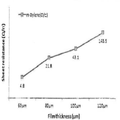
(1) 실시예 1 내지 3 및 비교예 1(1) Examples 1 to 3 and Comparative Example 1
상기 실시예 1 내지 3 및 비교예 1에 따른 신축 가능한 전도성 박막의 면 저항을 측정하였다. 그 결과는 하기 도 5에 나타내었다.The surface resistance of the stretchable conductive thin films according to Examples 1 to 3 and Comparative Example 1 was measured. The results are shown in FIG.
(2) 비교예 2 내지 5(2) Comparative Examples 2 to 5
상기 비교예 2 내지 5에 따른 신축 가능한 전도성 박막의 면 저항을 측정하였다. 그 결과는 하기 도 6에 나타내었다.The sheet resistances of the stretchable conductive thin films according to Comparative Examples 2 to 5 were measured. The results are shown in FIG.
(3) 비교예 6 내지 9(3) Comparative Examples 6 to 9
상기 비교예 6 내지 9에 따른 신축 가능한 전도성 박막의 면 저항을 측정하였다. 그 결과는 하기 도 7에 나타내었다.The sheet resistances of the stretchable conductive thin films according to Comparative Examples 6 to 9 were measured. The results are shown in FIG.
상기 도 5 내지 7을 참조하면, 박막의 두께가 두꺼워 질수록 면 저항이 증가하는 것을 확인할 수 있었다. 비교예에 따른 박막의 경우 두께 증가에 따른 면 저항 증가 폭이 현저히 높은 것을 알 수 있다. 특히, 박막의 두께가 80㎛일 때, 비교예에 따른 박막의 경우 면 저항 증가 폭이 현저히 높은 것을 알 수 있다. 구체적으로, 박막의 두께가 120㎛일 때, m-xylene을 사용하더라도(비교예 1) 면 저항이 1.44x10² Ω/sq로 측정되고, THF를 사용한 비교예 5의 면저항은 3.7x10⁷ Ω/sq로 나타나며, chloroform를 사용한 비교예 9의 면저항은 3.10x10⁷ Ω/sq로 나타나는 것을 알 수 있다. Referring to FIGS. 5 to 7, it can be seen that as the thickness of the thin film becomes thicker, the surface resistance increases. It can be seen that the increase of the surface resistance according to the increase of the thickness is remarkably high in the case of the thin film according to the comparative example. Particularly, when the thickness of the thin film is 80 탆, the increase of the surface resistance in the case of the thin film according to the comparative example is remarkably high. Specifically, when the thickness of the thin film was 120 μm, the sheet resistance was measured to be 1.44 × 10 2 Ω / sq (m-xylene) (Comparative Example 1), and the sheet resistance of Comparative Example 5 using THF was measured to be 3.7 × 10 7 Ω / sq, and the sheet resistance of Comparative Example 9 using chloroform is 3.10 x 10 7 Ω / sq.
이는, 본 발명에 따른 m-xylene 용매를 사용하며 80㎛의 두께를 갖는 박막(실시예 3)의 면 저항인 4.31x10과 비교하더라도, 최대 106배 이상 높은 수치인 것을 알 수 있다.
It can be seen that this is a value higher by at least 10 6 times than that of the thin film having the thickness of 80 탆 (m 3 xylene solvent according to the present invention) (4.31 × 10).
실험예Experimental Example 4: 신축성 실험 4: Stretch experiment
상기 실시예 1 내지 3, 비교예 1 내지 9에 따른 신축 가능한 전도성 박막에 대해서, 신장시키기 전(0%)에서 100% 신장시킨 후 각각의 박막의 저항을 측정하였다. 그 결과는 하기 도 8에 나타내었다.The stretchable conductive thin films according to Examples 1 to 3 and Comparative Examples 1 to 9 were stretched 100% before stretching (0%), and then the resistance of each thin film was measured. The results are shown in FIG.
도 8을 보면, m-xylene 용매를 사용한 실시예의 경우에는 두께 증가에 따른 면 저항 증가 추세가 박막의 신장시키지 않았을 때와 비슷한 경향을 보였고, 다른 용매를 사용하거나, 박막의 두께가 100㎛를 초과하는 경우의 비교예와 비교하여 현저히 낮은 면 저항을 나타내는 것을 알 수 있다.8, in the case of the example using m-xylene solvent, the tendency of surface resistance increase with increasing thickness was similar to that when the thin film was not elongated, and when another solvent was used, or when the thickness of the thin film exceeded 100 mu m The surface resistance is significantly lower than that of the comparative example.
Claims (11)
상기 신축성 고분자 박막에 화학적으로 결합된 금속 입자를 포함하며,
100% 신장 후, 면 저항은 60x104 Ω/sq 이하인 신축 가능한 전도성 박막.
Stretch polymer thin film; And
And metal particles chemically bonded to the stretch polymer thin film,
A stretchable conductive thin film having a sheet resistance of 60 x 10 4 ? / Sq or less after 100% elongation.
신축성 고분자는 폴리부타디엔(PB), 폴리(스티렌-부타디엔)(PS-b-PB, PS-co-PB), 폴리(스티렌-부타디엔-스티렌)(PS-b-PB-b-PS)(SBS), 폴리(스티렌-에틸렌-부틸렌-스티렌)(SEBS), 폴리우레탄(PU) 및 폴리이소프렌 중 1 종 이상을 포함하는 신축 가능한 전도성 박막.
The method according to claim 1,
The stretchable polymers include polybutadiene (PB), poly (styrene-butadiene) (PS-b-PB, PS-co-PB), poly (styrene-butadiene- ), Poly (styrene-ethylene-butylene-styrene) (SEBS), polyurethane (PU) and polyisoprene.
금속 입자는, 금, 은, 구리 및 백금 중 1 종 이상을 포함하는 신축 가능한 전도성 박막.
The method according to claim 1,
The metal particles include at least one of gold, silver, copper, and platinum.
평균 두께는 30 내지 100 ㎛ 범위인 신축 가능한 전도성 박막.
The method according to claim 1,
The stretchable conductive thin film has an average thickness in the range of 30 to 100 mu m.
상기 박막을 금속 전구체 용액에 침지하고 환원제를 이용하여 금속을 환원시키는 단계를 포함하는 신축 가능한 전도성 박막의 제조방법.
Preparing a solution of xylene and a stretch polymer in a thin film through a spin coating process; And
Immersing the thin film in a metal precursor solution and reducing the metal using a reducing agent.
자일렌 및 신축성 고분자를 혼합한 용액 100 중량부를 기준으로,
신축성 고분자는 25 내지 40 중량부를 포함하는 신축 가능한 전도성 박막의 제조방법.
6. The method of claim 5,
Based on 100 parts by weight of a solution prepared by mixing xylene and a stretchable polymer,
Wherein the stretchable polymer comprises 25 to 40 parts by weight of the stretchable polymer.
스핀코팅은 500 내지 2500 RPM으로, 1 내지 60 초 동안 수행하는 신축 가능한 전도성 박막의 제조방법.
6. The method of claim 5,
Wherein the spin coating is performed at 500 to 2500 RPM for 1 to 60 seconds.
금속 전구체 용액은 AgTFA, AgNO3, AgCl, HAuCl4, CuCl2, PtCl2 및 PtCl4 중 1 종 이상을 포함하는 신축 가능한 전도성 박막의 제조방법.
6. The method of claim 5,
Metal precursor solution AgTFA, AgNO 3, AgCl, HAuCl 4, CuCl 2, PtCl 2 , and PtCl 4 1 process for producing a stretchable conductive thin film containing at least one of.
환원제는 히드라진 화합물 및 붕수소나트륨 화합물 중 1 종 이상을 포함하는 신축 가능한 전도성 박막의 제조방법.
6. The method of claim 5,
Wherein the reducing agent comprises at least one of a hydrazine compound and a sodium borohydride compound.
A stretchable electrode comprising the stretchable conductive thin film according to claim 1.
Priority Applications (1)
| Application Number | Priority Date | Filing Date | Title |
|---|---|---|---|
| KR1020170025363A KR20180098792A (en) | 2017-02-27 | 2017-02-27 | Strechable conductive film, manufacturing method of the same and uses thereof |
Applications Claiming Priority (1)
| Application Number | Priority Date | Filing Date | Title |
|---|---|---|---|
| KR1020170025363A KR20180098792A (en) | 2017-02-27 | 2017-02-27 | Strechable conductive film, manufacturing method of the same and uses thereof |
Publications (1)
| Publication Number | Publication Date |
|---|---|
| KR20180098792A true KR20180098792A (en) | 2018-09-05 |
Family
ID=63594185
Family Applications (1)
| Application Number | Title | Priority Date | Filing Date |
|---|---|---|---|
| KR1020170025363A Withdrawn KR20180098792A (en) | 2017-02-27 | 2017-02-27 | Strechable conductive film, manufacturing method of the same and uses thereof |
Country Status (1)
| Country | Link |
|---|---|
| KR (1) | KR20180098792A (en) |
Citations (1)
| Publication number | Priority date | Publication date | Assignee | Title |
|---|---|---|---|---|
| KR20130097151A (en) | 2010-07-08 | 2013-09-02 | 오스람 옵토 세미컨덕터스 게엠베하 | Optoelectronic device having an elastic electrode |
-
2017
- 2017-02-27 KR KR1020170025363A patent/KR20180098792A/en not_active Withdrawn
Patent Citations (1)
| Publication number | Priority date | Publication date | Assignee | Title |
|---|---|---|---|---|
| KR20130097151A (en) | 2010-07-08 | 2013-09-02 | 오스람 옵토 세미컨덕터스 게엠베하 | Optoelectronic device having an elastic electrode |
Similar Documents
| Publication | Publication Date | Title |
|---|---|---|
| Hong et al. | UV curable conductive ink for the fabrication of textile-based conductive circuits and wearable UHF RFID tags | |
| EP2557207B1 (en) | Stretchable conductive nanofibers, stretchable electrode using the same and method of producing the stretchable conductive nanofibers | |
| Lv et al. | Printed sustainable elastomeric conductor for soft electronics | |
| Zhao et al. | Preparation of a self-healing polyaniline-based gel and its application as a healable all-in-one capacitor | |
| US20120251824A1 (en) | Stretchable Conductive Nanofibers, Stretchable Fiber Electrode Using The Same And Method For Producing The Same | |
| EP3286767B1 (en) | Highly conductive polymer film compositions from nanoparticle induced phase segregation of counterion templates from conducting polymers | |
| CN102906165A (en) | Method of producing electrically conductive polymer and cellulose nanocomposites | |
| CN103367247A (en) | Method for carrying out selective area deposition of silver nano particles on surface of PDMS (Polydimethylsiloxane) elastic body | |
| CN113382959A (en) | Method for producing N-doped graphene films | |
| WO2023175055A1 (en) | Autonomous self-healing, transparent, electrically conducting elastomer and method of making the same | |
| Lerond et al. | Enhancing the performance of transparent and highly stretchable organic electrochemical transistors by acid treatment and copolymer blending of electrospun PEDOT: PSS fibers | |
| JP2007533109A (en) | Electrically conductive elastomer, method of manufacturing the same and article containing | |
| CN101164122B (en) | Conductive material, conductive film and their manufacturing method | |
| CN101669223A (en) | Organic sensor device and application thereof | |
| Muhammad et al. | Highly sensitive and flexible micro-patterned PPy/PDMS strain sensors with enhanced conductivity and stretchability for wearable electronics | |
| KR20150066552A (en) | Transparent electrode and associated production method | |
| US20250206897A1 (en) | Autonomous self-healing, transparent, electrically conducting elastomer and method of making the same | |
| Li et al. | Aligned wave-like elastomer fibers with robust conductive layers via electroless deposition for stretchable electrode applications | |
| CN110724307B (en) | Preparation method of renewable cellulose conductive film with stable flexible conductivity | |
| KR20180098792A (en) | Strechable conductive film, manufacturing method of the same and uses thereof | |
| KR101999488B1 (en) | Method for removal of polymer residues on a graphene film | |
| US12305056B2 (en) | Liquid metal particle-assembled network synthesized in various polymers, and manufacturing method of the same | |
| EP3734830A1 (en) | Method for the manufacture of a triboelectric device | |
| EP3901359B1 (en) | Electric conductive textile and method for fabricating the same | |
| CN112615105B (en) | Preparation method for battery porous film, battery diaphragm and battery |
Legal Events
| Date | Code | Title | Description |
|---|---|---|---|
| PA0109 | Patent application |
Patent event code: PA01091R01D Comment text: Patent Application Patent event date: 20170227 |
|
| PG1501 | Laying open of application | ||
| PC1203 | Withdrawal of no request for examination | ||
| WITN | Application deemed withdrawn, e.g. because no request for examination was filed or no examination fee was paid |