KR20180098763A - Air conditioner - Google Patents
Air conditioner Download PDFInfo
- Publication number
- KR20180098763A KR20180098763A KR1020170025287A KR20170025287A KR20180098763A KR 20180098763 A KR20180098763 A KR 20180098763A KR 1020170025287 A KR1020170025287 A KR 1020170025287A KR 20170025287 A KR20170025287 A KR 20170025287A KR 20180098763 A KR20180098763 A KR 20180098763A
- Authority
- KR
- South Korea
- Prior art keywords
- refrigerant
- heat exchanger
- pipe
- outdoor heat
- inlet
- Prior art date
- Legal status (The legal status is an assumption and is not a legal conclusion. Google has not performed a legal analysis and makes no representation as to the accuracy of the status listed.)
- Withdrawn
Links
Images

Classifications
-
- F—MECHANICAL ENGINEERING; LIGHTING; HEATING; WEAPONS; BLASTING
- F25—REFRIGERATION OR COOLING; COMBINED HEATING AND REFRIGERATION SYSTEMS; HEAT PUMP SYSTEMS; MANUFACTURE OR STORAGE OF ICE; LIQUEFACTION SOLIDIFICATION OF GASES
- F25B—REFRIGERATION MACHINES, PLANTS OR SYSTEMS; COMBINED HEATING AND REFRIGERATION SYSTEMS; HEAT PUMP SYSTEMS
- F25B39/00—Evaporators; Condensers
- F25B39/04—Condensers
-
- F—MECHANICAL ENGINEERING; LIGHTING; HEATING; WEAPONS; BLASTING
- F25—REFRIGERATION OR COOLING; COMBINED HEATING AND REFRIGERATION SYSTEMS; HEAT PUMP SYSTEMS; MANUFACTURE OR STORAGE OF ICE; LIQUEFACTION SOLIDIFICATION OF GASES
- F25B—REFRIGERATION MACHINES, PLANTS OR SYSTEMS; COMBINED HEATING AND REFRIGERATION SYSTEMS; HEAT PUMP SYSTEMS
- F25B39/00—Evaporators; Condensers
- F25B39/02—Evaporators
- F25B39/028—Evaporators having distributing means
-
- F—MECHANICAL ENGINEERING; LIGHTING; HEATING; WEAPONS; BLASTING
- F25—REFRIGERATION OR COOLING; COMBINED HEATING AND REFRIGERATION SYSTEMS; HEAT PUMP SYSTEMS; MANUFACTURE OR STORAGE OF ICE; LIQUEFACTION SOLIDIFICATION OF GASES
- F25B—REFRIGERATION MACHINES, PLANTS OR SYSTEMS; COMBINED HEATING AND REFRIGERATION SYSTEMS; HEAT PUMP SYSTEMS
- F25B40/00—Subcoolers, desuperheaters or superheaters
- F25B40/02—Subcoolers
-
- F25B41/003—
-
- F25B41/04—
-
- F25B41/067—
-
- F—MECHANICAL ENGINEERING; LIGHTING; HEATING; WEAPONS; BLASTING
- F25—REFRIGERATION OR COOLING; COMBINED HEATING AND REFRIGERATION SYSTEMS; HEAT PUMP SYSTEMS; MANUFACTURE OR STORAGE OF ICE; LIQUEFACTION SOLIDIFICATION OF GASES
- F25B—REFRIGERATION MACHINES, PLANTS OR SYSTEMS; COMBINED HEATING AND REFRIGERATION SYSTEMS; HEAT PUMP SYSTEMS
- F25B41/00—Fluid-circulation arrangements
- F25B41/20—Disposition of valves, e.g. of on-off valves or flow control valves
-
- F—MECHANICAL ENGINEERING; LIGHTING; HEATING; WEAPONS; BLASTING
- F25—REFRIGERATION OR COOLING; COMBINED HEATING AND REFRIGERATION SYSTEMS; HEAT PUMP SYSTEMS; MANUFACTURE OR STORAGE OF ICE; LIQUEFACTION SOLIDIFICATION OF GASES
- F25B—REFRIGERATION MACHINES, PLANTS OR SYSTEMS; COMBINED HEATING AND REFRIGERATION SYSTEMS; HEAT PUMP SYSTEMS
- F25B41/00—Fluid-circulation arrangements
- F25B41/30—Expansion means; Dispositions thereof
- F25B41/37—Capillary tubes
-
- F—MECHANICAL ENGINEERING; LIGHTING; HEATING; WEAPONS; BLASTING
- F25—REFRIGERATION OR COOLING; COMBINED HEATING AND REFRIGERATION SYSTEMS; HEAT PUMP SYSTEMS; MANUFACTURE OR STORAGE OF ICE; LIQUEFACTION SOLIDIFICATION OF GASES
- F25B—REFRIGERATION MACHINES, PLANTS OR SYSTEMS; COMBINED HEATING AND REFRIGERATION SYSTEMS; HEAT PUMP SYSTEMS
- F25B41/00—Fluid-circulation arrangements
- F25B41/40—Fluid line arrangements
- F25B41/42—Arrangements for diverging or converging flows, e.g. branch lines or junctions
-
- F—MECHANICAL ENGINEERING; LIGHTING; HEATING; WEAPONS; BLASTING
- F25—REFRIGERATION OR COOLING; COMBINED HEATING AND REFRIGERATION SYSTEMS; HEAT PUMP SYSTEMS; MANUFACTURE OR STORAGE OF ICE; LIQUEFACTION SOLIDIFICATION OF GASES
- F25B—REFRIGERATION MACHINES, PLANTS OR SYSTEMS; COMBINED HEATING AND REFRIGERATION SYSTEMS; HEAT PUMP SYSTEMS
- F25B2339/00—Details of evaporators; Details of condensers
- F25B2339/02—Details of evaporators
-
- F—MECHANICAL ENGINEERING; LIGHTING; HEATING; WEAPONS; BLASTING
- F25—REFRIGERATION OR COOLING; COMBINED HEATING AND REFRIGERATION SYSTEMS; HEAT PUMP SYSTEMS; MANUFACTURE OR STORAGE OF ICE; LIQUEFACTION SOLIDIFICATION OF GASES
- F25B—REFRIGERATION MACHINES, PLANTS OR SYSTEMS; COMBINED HEATING AND REFRIGERATION SYSTEMS; HEAT PUMP SYSTEMS
- F25B2339/00—Details of evaporators; Details of condensers
- F25B2339/04—Details of condensers
Landscapes
- Engineering & Computer Science (AREA)
- Physics & Mathematics (AREA)
- Mechanical Engineering (AREA)
- Thermal Sciences (AREA)
- General Engineering & Computer Science (AREA)
- Other Air-Conditioning Systems (AREA)
Abstract
Description
본 발명은 공기 조화기에 관한 것이다.The present invention relates to an air conditioner.
공기 조화기는 소정공간의 공기를 용도, 목적에 따라 가장 적합한 상태로 유지하기 위한 기기이다. 일반적으로, 상기 공기 조화기에는, 압축기, 응축기, 팽창장치 및 증발기가 포함되며, 냉매의 압축, 응축, 팽창 및 증발과정을 수행하는 냉매 사이클이 구동되어, 상기 소정공간을 냉방 또는 난방할 수 있다.The air conditioner is a device for keeping the air in a predetermined space in a most suitable condition according to the purpose of use and purpose. Generally, the air conditioner includes a compressor, a condenser, an expansion device, and an evaporator, and a refrigerant cycle for compressing, condensing, expanding, and evaporating the refrigerant is driven to cool or heat the predetermined space .
상기 소정공간은 상기 공기 조화기가 사용되는 장소에 따라, 다양하게 제안될 수 있다. 예를 들어, 상기 공기 조화기가 가정이나 사무실에 배치되는 경우, 상기 소정공간은 집 또는 건물의 실내 공간일 수 있다. 또한, 상기 공기 조화기가 자동차에 배치되는 경우, 상기 소정 공간은 사람이 탑승하는 탑승 공간일 수 있다.The predetermined space may be variously suggested depending on the place where the air conditioner is used. For example, when the air conditioner is installed in a home or an office, the predetermined space may be an indoor space of a house or a building. In addition, when the air conditioner is disposed in a vehicle, the predetermined space may be a boarding space on which a person is boarded.
공기 조화기가 냉방 운전을 수행하는 경우, 실외기에 구비되는 실외 열교환기가 응축기 기능을 하며 실내기에 구비되는 실내 열교환기가 증발기 기능을 수행한다. 또한, 공기 조화기가 난방 운전을 수행하는 경우, 상기 실내 열교환기가 응축기 기능을 하며 상기 실외 열교환기가 증발기 기능을 수행한다.When the air conditioner performs the cooling operation, the outdoor heat exchanger provided in the outdoor unit functions as a condenser, and the indoor heat exchanger provided in the indoor unit functions as an evaporator. Further, when the air conditioner performs the heating operation, the indoor heat exchanger functions as a condenser and the outdoor heat exchanger functions as an evaporator.
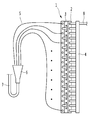
도 1은 종래의 공기조화기의 열교환기 및 그 주변 구성을 보여주는 도면이다.1 is a view showing a heat exchanger of a conventional air conditioner and its peripheral structure.
도 1을 참조하면, 종래의 공기조화기에는, 열교환기(1) 및 상기 열교환기(1)에 결합되어 냉매가 입출되는 배관 등이 포함된다.Referring to FIG. 1, the conventional air conditioner includes a
상기 열교환기(1)에는, 복수의 열로 배열되는 복수의 냉매관(2)과, 상기 냉매관(2)의 단부가 결합되며 상기 냉매관(2)을 지지하는 결합 플레이트(3) 및 상기 냉매관(2)으로 냉매를 분지하거나 상기 냉매관(2)을 통과한 냉매가 합지되도록 하는 헤더(4)가 포함된다.The
상기 헤더(4)는 상기 냉매관(2)의 배열 방향에 따라 일 방향으로 길게 연장될 수 있다. 예를 들어, 상기 헤더(4)는 도 1에 도시된 바와 같이, 상하 방향으로 연장될 수 있다.The header 4 may be elongated in one direction along the arrangement direction of the refrigerant pipe 2. For example, the header 4 may extend vertically as shown in FIG.
상기 열교환기(1)의 일 측에는 입출배관(8)이 연결된다. 자세하게는, 상기 입출배관(8)은 상기 헤더(4)와 연결되어, 냉매를 상기 헤더(4)로 가이드하거나 상기 헤더(4)에서 토출된 냉매를 가이드한다.An inlet / outlet pipe (8) is connected to one side of the heat exchanger (1). In detail, the inlet / outlet pipe 8 is connected to the header 4 to guide the refrigerant to the header 4 or to guide the refrigerant discharged from the header 4.
또한, 상기 열교환기(1)의 타 측에는 분지배관(5)이 연결된다. 상기 분지배관(5)에는, 캐필러리 튜브(capillary tube)가 포함될 수 있다. 자세하게는, 상기 분지배관(5)은 상기 결합 플레이트(3)에 연결되어, 냉매를 상기 결합 플레이트(3)측으로 유동시키거나 상기 결합 플레이트(3) 측에서 토출된 냉매를 유동시킨다.A branch pipe (5) is connected to the other side of the heat exchanger (1). The branch pipe 5 may include a capillary tube. Specifically, the branch pipe 5 is connected to the coupling plate 3 to cause the refrigerant to flow toward the coupling plate 3 or the refrigerant discharged from the coupling plate 3 side.
또한, 상기 공기조화기에는, 분배기(6)가 더 포함된다. 상기 분배기(6)는, 상기 분지배관(5)을 통하여 유입된 냉매를 합지하거나, 분배기 연결관(7)으로 유입된 냉매를 상기 분지배관(5)으로 분지하도록 구성된다.The air conditioner further includes a distributor (6). The distributor 6 is configured to mix the refrigerant introduced through the branch pipe 5 or branch the refrigerant introduced into the
이와 같은 열교환기(1)에 있어서, 냉매의 유동방향은 냉방 및 난방 운전시 반대로 형성된다. 이하에서는, 상기 열교환기(1)가 "실외 열교환기"인 경우를 예로 들어 설명한다.In such a heat exchanger (1), the flow direction of the refrigerant is reversely formed in the cooling and heating operation. Hereinafter, the case where the
공기 조화기가 냉방 운전을 하는 경우, 상기 실외 열교환기(1)는 응축기로서 기능을 수행한다. 상세히, 상기 압축기에서 압축된 고압의 냉매는 상기 헤더(4)로 유입되어 복수의 냉매관(2)으로 분지되며, 상기 복수의 냉매관(2)을 유동하면서 실외공기와 열교환 된다. 상기 열교환 된 냉매는 상기 복수의 분지배관(5)을 거쳐 상기 분배기(6)에서 합지된 후 실내기 측으로 유동된다.When the air conditioner performs cooling operation, the outdoor heat exchanger (1) functions as a condenser. In detail, the high-pressure refrigerant compressed in the compressor flows into the header 4, is branched into a plurality of refrigerant tubes 2, and is heat-exchanged with outdoor air while flowing through the plurality of refrigerant tubes 2. The heat-exchanged refrigerant flows through the plurality of branch pipes (5) to the distributor (6) and flows to the indoor unit side.
반면에, 공기 조화기가 난방 운전을 하는 경우, 상기 실외 열교환기(1)는 증발기로서 기능을 수행한다. 상세히, 실내기를 통과한 냉매는 상기 분배기 연결관(7)을 통하여 상기 분배기(6)로 유입된다. 그리고, 냉매는 상기 분배기(6)에 연결된 상기 복수의 분지배관(5)을 통하여 상기 냉매관(2)으로 유입되며, 상기 냉매관(2)에서 열교환 된 냉매는 상기 헤더(4)에서 합지되어 상기 압축기 측으로 유동될 수 있다.On the other hand, when the air conditioner performs heating operation, the
최근 부분부하 효율이 강조되고 있고, 이에 대응하기 위한 압축기 주파수를 최소화하여 공기조화기를 유동하는 냉매 유량이 점점 작아지고 있다. 냉매의 유량이 작아짐에 따라, 냉매는 중력의 영향을 비교적 많이 받게 된다. 또한, 상기 열교환기가 상하방향으로 커짐에 따라 상부와 하부 간의 중력영향이 상이하게 된다.Recently, the partial load efficiency has been emphasized, and the frequency of the compressor for minimizing the frequency of the partial load has been minimized, and the flow rate of the refrigerant flowing in the air conditioner is gradually decreasing. As the flow rate of the refrigerant becomes smaller, the refrigerant is relatively affected by gravity. Further, as the heat exchanger increases in the vertical direction, the influence of gravity between the upper part and the lower part becomes different.
그에 따라, 비교적 중력의 영향을 적게 받는 상기 열교환기의 상부는 냉매의 유량이 커지고, 비교적 중력의 영향을 크게 받는 상기 열교환기의 하부는 냉매의 유량이 작아지는 문제점이 있다. 즉, 상기 열교환기 내부에 유로 간의 불균형이 발생된다.Accordingly, the flow rate of the refrigerant in the upper portion of the heat exchanger, which is relatively less influenced by gravity, becomes large, and the flow rate of the refrigerant in the lower portion of the heat exchanger, which is relatively influenced by gravity, is reduced. That is, an unbalance between the flow paths is generated in the heat exchanger.
특히, 유량이 커지는 상기 열교환기의 상부유로에는 열교환이 충분히 이루어지지 않아 과냉도가 확보되지 않는 문제점이 있다. 또한, 유량이 작아지는 상기 열교환기의 하부유로에는 유로 내부에 액냉매가 쌓이게 되어 유로저항이 커지는 문제점이 있다. 그에 따라, 상기 열교환기의 효율이 떨어지고 운전성능이 확보되지 못한다.Particularly, there is a problem that heat exchange is not sufficiently performed in the upper flow path of the heat exchanger in which the flow rate is increased, and the subcooling degree is not ensured. Further, liquid refrigerant accumulates in the lower flow path of the heat exchanger in which the flow rate is decreased, thereby increasing the flow path resistance. As a result, the efficiency of the heat exchanger is lowered and the operation performance is not ensured.
본 발명은 이러한 문제점을 해결하기 위하여 제안된 것으로서, 열교환 효율 및 운전성능이 개선된 공기 조화기를 제공하는 것을 목적으로 한다.SUMMARY OF THE INVENTION It is an object of the present invention to provide an air conditioner having improved heat exchange efficiency and operation performance.
본 발명의 실시 예에 따른 공기 조화기에는, 압축기, 응축기, 팽창밸브 및 증발기로 구성된 공기조화기에 있어서, 상기 응축기에는, 상하방향으로 이격되어 마련되는 복수의 냉매배관 및 상기 복수의 냉매배관에 결합되도록, 상하방향으로 연장된 높이(H)를 갖는 헤더가 포함되고, 상기 응축기로 냉매를 유입시키도록 마련된 유입배관은, 상기 헤더의 중심보다 하부에 설치될 수 있다.An air conditioner according to an embodiment of the present invention includes a compressor, a condenser, an expansion valve, and an evaporator, wherein the condenser is provided with a plurality of refrigerant pipes spaced apart from each other in the vertical direction, A header having a height H extending in the up and down direction is included so that the inlet pipe provided to introduce the refrigerant into the condenser can be installed below the center of the header.
상기 유입배관은, 상기 헤더의 하단에서 상기 헤더 높이의 3분의 1지점(H/3) 사이에 설치될 수 있다.The inflow pipe may be installed between the lower end of the header and a third point (H / 3) of the height of the header.
상기 유입배관은 상기 복수의 냉매배관 중 어느 하나와 수평하게 위치되도록 설치될 수 있다.The inflow pipe may be installed horizontally with any one of the plurality of refrigerant pipes.
상기 유입배관에는, 상기 복수의 냉매배관 중 어느 하나와 각각 수평하게 위치되는 제 1 유입배관 및 제 2 유입배관이 포함될 수 있다.The inflow pipe may include a first inflow pipe and a second inflow pipe which are positioned horizontally with any one of the plurality of refrigerant pipes.
상기 유입배관에는, 유입되는 냉매를 분배하도록, 상하로 길게 연장되어 상기 헤더에 각각 연결되는 분지관이 더 포함될 수 있다.The inflow pipe may further include a branch pipe extending upward and downward so as to distribute the inflow refrigerant and connected to the header.
상기 응축기 또는 상기 증발기로 기능하는 실외 열교환기, 상기 실외 열교환기의 일 측에 연결되는 제 1 입출배관 및 상기 실외 열교환기의 타 측으로부터 상기 팽창밸브로 연장되는 제 2 입출배관이 더 포함될 수 있다.An outdoor heat exchanger functioning as the condenser or the evaporator, a first inlet / outlet pipe connected to one side of the outdoor heat exchanger, and a second inlet / outlet pipe extending from the other side of the outdoor heat exchanger to the expansion valve .
상기 제 1 입출배관에는, 상기 실외 열교환기의 상부에 결합되는 상부배관 및 상기 실외 열교환기의 하부에 결합되는 하부배관이 포함될 수 있다.The first inlet / outlet pipe may include an upper pipe coupled to an upper portion of the outdoor heat exchanger and a lower pipe coupled to a lower portion of the outdoor heat exchanger.
상기 상부배관에는 상기 실외 열교환기로 유입되는 냉매의 유동을 차단하는 체크밸브가 설치될 수 있다.The upper pipe may be provided with a check valve for blocking the flow of the refrigerant flowing into the outdoor heat exchanger.
상기 상부배관 및 상기 하부배관은, 상기 실외 열교환기의 상단 및 하단으로부터 동일한 거리로 이격되어 배치될 수 있다.The upper piping and the lower piping may be disposed at equal distances from upper and lower ends of the outdoor heat exchanger.
상기 제 2 입출배관과 상기 실외 열교환기의 사이에는, 분배기 및 상기 분배기와 상기 실외 열교환기를 연결하는 복수의 캐필러리 튜브가 배치될 수 있다.And a plurality of capillary tubes connecting the distributor and the outdoor heat exchanger may be disposed between the second inlet / outlet pipe and the outdoor heat exchanger.
이러한 본 발명에 의하면, 응축기의 유입배관을 하부에 배치함으로서 중력에 의한 유량의 불균형을 감소시킬 수 있다.According to the present invention, by disposing the inflow pipe of the condenser at the lower part, it is possible to reduce unevenness of the flow rate due to gravity.
특히, 과냉도가 더 크게 형성되는 하부측으로 유입배관을 설치하여 유동하는 냉매량을 증가시킬 수 있다. 즉, 유입배관과 하부 냉매배관 사이의 거리가 짧아짐에 따라 압력손실을 최소화할 수 있다.In particular, it is possible to increase the amount of refrigerant flowing by installing the inflow pipe to the lower side where the subcooling degree is larger. That is, as the distance between the inflow pipe and the lower refrigerant pipe is shortened, the pressure loss can be minimized.
또한, 유량의 분균형에 따라 과냉도가 확보되지 않는 상부측은 냉매량이 비교적 감소하여, 냉매의 충분한 과냉도를 확보할 수 있다. 즉, 유입배관과 상부 냉매배관 사이의 거리가 길어짐에 따라 압력손실이 비교적 많아질 수 있다.Further, the amount of refrigerant is relatively reduced in the upper side where the subcooling degree can not be ensured due to the balance of the flow rate, and sufficient subcooling of the refrigerant can be ensured. That is, as the distance between the inflow pipe and the upper refrigerant pipe becomes longer, the pressure loss can be relatively increased.
또한, 실외 열교환기가 비교적 중력의 영향을 받지 않는 증발기로 사용되는 경우, 상부배관을 더 구비하여 유량의 균형을 도모할 수 있다.In addition, when the outdoor heat exchanger is used as an evaporator which is relatively free from the effect of gravity, it is possible to further provide an upper pipeline to balance the flow rate.
또한, 실외 열교환기가 중력의 영향을 받는 응축기로 사용되는 경우, 상부배관을 폐쇄하는 체크밸브를 구비하여 상기 실외 열교환기의 하부로만 냉매를 유입시켜 유량의 균형을 도모할 수 있다.Further, when the outdoor heat exchanger is used as a condenser affected by gravity, a check valve for closing the upper piping is provided, so that the refrigerant can be flowed only into the lower portion of the outdoor heat exchanger to balance the flow rate.
도 1은 종래의 공기조화기의 열교환기 및 그 주변 구성을 보여주는 도면이다.
도 2는 본 발명의 일 실시 예에 따른 공기 조화기의 구성을 보여주는 시스템 도면이다.
도 3은 본 발명의 일 실시 예에 따른 공기조화기의 열교환기 및 그 주변 구성을 보여주는 도면이다.
도 4는 본 발명의 다른 실시 예에 따른 공기조화기의 열교환기 및 그 주변 구성을 보여주는 도면이다.
도 5는 본 발명의 또 다른 실시 예에 따른 공기조화기의 열교환기 및 그 주변 구성을 보여주는 도면이다.1 is a view showing a heat exchanger of a conventional air conditioner and its peripheral structure.
2 is a system diagram showing the configuration of an air conditioner according to an embodiment of the present invention.
FIG. 3 is a view illustrating a heat exchanger of the air conditioner according to an embodiment of the present invention and a peripheral structure thereof.
4 is a view showing a heat exchanger of the air conditioner according to another embodiment of the present invention and a peripheral structure thereof.
5 is a view showing a heat exchanger of the air conditioner according to another embodiment of the present invention and a peripheral structure thereof.
이하에서는 도면을 참조하여, 본 발명의 구체적인 실시 예를 설명한다. 다만, 본 발명의 사상은 제시되는 실시 예에 제한되지 아니하며, 본 발명의 사상을 이해하는 당업자는 동일한 사상의 범위 내에서 다른 실시 예를 용이하게 제안할 수 있을 것이다.Hereinafter, specific embodiments of the present invention will be described with reference to the drawings. It is to be understood, however, that the spirit of the invention is not limited to the embodiments shown and that those skilled in the art, upon reading and understanding the spirit of the invention, may easily suggest other embodiments within the scope of the same concept.
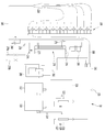
도 2는 본 발명의 일 실시 예에 따른 공기 조화기의 구성을 보여주는 시스템 도면이다.2 is a system diagram showing the configuration of an air conditioner according to an embodiment of the present invention.
도 2를 참조하면, 본 발명의 실시 예에 따른 공기 조화기(10)에는, 실외에 배치되는 실외기 및 실내에 배치되는 실내기가 포함된다. 상기 실내기에는, 실내 공간의 공기와 열교환 되는 실내 열교환기가 포함된다. 설명의 편의상 도 2에는, 상기 실외기의 구성만 도시하였다.Referring to FIG. 2, the
상기 공기 조화기(10)에는, 복수의 압축기(110, 112)와, 상기 복수의 압축기(110, 120)의 출구 측에 배치되며 상기 복수의 압축기(110, 120)에서 토출된 냉매 중 오일을 분리하기 위한 오일 분리기(120, 122)가 포함된다.The air conditioner (10) is provided with a plurality of compressors (110, 112), and an oil cooler disposed at an outlet side of the plurality of compressors (110, 120)
상기 복수의 압축기(110, 112)에는, 병렬 연결되는 제 1 압축기(110) 및 제 2 압축기(112)가 포함된다. 상기 제 1 압축기(110) 및 제 2 압축기(112)의 출구 측에는, 압축된 냉매의 온도를 감지하는 토출온도 센서(114)가 각각 제공될 수 있다.The plurality of
그리고, 상기 오일 분리기(120, 122)에는, 상기 제 1 압축기(110)의 출구 측에 배치되는 제 1 오일 분리기(120) 및 상기 제 2 압축기(112)의 출구 측에 배치되는 제 2 오일 분리기(122)가 포함된다.The
상기 공기 조화기(10)에는, 상기 오일 분리기(120, 122)로부터 상기 압축기(110, 112)로 오일을 회수하기 위한 회수 유로(116)가 포함된다. 상기 회수유로(116)는 상기 제 1, 2 오일분리기(120, 122)의 각 출구 측으로부터 각각 연장되어 합지되며, 합지된 유로는 상기 제 1, 2 압축기(110, 112)의 입구 측 배관에 연결될 수 있다.The
상기 회수 유로(116)에는, 드라이어(127) 및 캐필러리(128)가 설치될 수 잇다. 상기 드라이어(127) 및 상기 캐필러리(128)는 상기 제 1, 2 오일분리기(120, 122)의 각 출구 측에 각각 제공될 수 있다.A dryer 127 and a capillary 128 may be installed in the
또한, 상기 오일 분리기(120, 122)의 출구 측에는, 상기 압축기(110, 112)에서 토출된 냉매의 토출 고압을 감지하기 위한 고압센서(125) 및 상기 고압센서(125)를 거친 냉매를 실외 열교환기(200) 또는 실내기 측으로 가이드 하는 유동 전환부(130)가 제공된다. 예를 들어, 상기 유동 전환부(130)에는, 사방 밸브가 포함될 수 있다.A
상기 공기 조화기(10)가 냉방 운전하는 경우, 냉매는 상기 유동 전환부(130)로부터 제 1 입출배관(300)을 거쳐 상기 실외 열교환기(200)로 유입된다. 상기 제 1 입출배관(300)은 상기 유동 전환부(130)로부터 상기 실외 열교환기(200)로 연장되는 배관으로서 이해된다.When the
상기 실외 열교환기(200)에서 응축된 냉매는 제 2 입출배관(145)을 거쳐 메인 팽창밸브(260, 전자팽창밸브, EEV, Electric Expansion Valve)를 통과한다. 즉, 상기 메인 팽창밸브(260)는, 냉방 운전을 기준으로 상기 실외 열교환기(200)의 출구 측에 설치될 수 있다. 그리고, 상기 제 2 입출배관(145)은 상기 실외 열교환기(200)로부터 상기 메인 팽창밸브(260)로 연장되는 배관으로서 이해된다.The refrigerant condensed in the
상기 메인 팽창밸브(260)를 통과한 냉매는 방열판(265)을 통과하게 된다. 상기 방열판(265)은 발열 부품이 구비되는 전장 유닛에 제공될 수 있다.The refrigerant passing through the main expansion valve (260) passes through the heat sink (265). The heat dissipation plate 265 may be provided in an electrical unit provided with a heat generating component.
예를 들어, 상기 발열부품에는 전원 모듈(IPM, Intelligent Power Module, 지능형 전력모듈)이 포함될 수 있다. 상기 전원 모듈은 전력을 제어하는 전력 모스 펫(MOS FET, Metal Oxide Silicon Field Effect Transistor)이나 IGBT(Insulated Gate Bipolar mode Transistor) 등의 전력장치의 구동회로 및 자기보호 기능의 보호회로를 설치한 모듈로서 이해된다. For example, the heat generating component may include an IPM (Intelligent Power Module). The power module is a module provided with a drive circuit for a power device such as a power MOSPET (Metal Oxide Silicon Field Effect Transistor) or an IGBT (Insulated Gate Bipolar mode Transistor) and a protective circuit for a magnetic protection function I understand.
상기 응축된 냉매의 유동을 가이드 하는 냉매 배관은 상기 방열판(265)에 결합되어, 상기 발열부품을 냉각시키게 된다.The refrigerant pipe guiding the flow of the condensed refrigerant is coupled to the heat sink 265 to cool the heat generating component.
상기 공기 조화기(10)에는, 상기 방열판(265)을 거친 냉매가 유입되는 과냉각 열교환기(270) 및 상기 과냉각 열교환기(270)의 입구 측에 제공되어 냉매를 분지하는 과냉각 분배기(271)가 더 포함된다. 상기 과냉각 열교환기(270)는 시스템을 순환하는 제 1 냉매와, 상기 제 1 냉매 중 일부의 냉매(제 2 냉매)가 분지된 후 열교환되는 중간 열교환기로서 기능한다. The
여기서, 상기 제 1 냉매는 상기 과냉각 분배기(271)를 거쳐 상기 과냉각 열교환기(270)로 유입되는 냉매이며 상기 제 2 냉매에 의하여 과냉각 될 수 있다. 반면에, 상기 제 2 냉매는 상기 제 1 냉매로부터 흡열할 수 있다.Here, the first refrigerant is a refrigerant flowing into the
상기 공기 조화기(10)에는, 상기 과냉각 열교환기(270)의 출구 측에 제공되어 상기 제 1 냉매로부터 제 2 냉매가 분지되도록 하는 과냉각 유로(273)가 포함된다. 그리고, 상기 과냉각 유로(273)에는, 상기 제 2 냉매를 감압하기 위한 과냉각 팽창장치(275)가 제공된다. 상기 과냉각 팽창장치(275)에는, 전자팽창밸브(EEV)가 포함될 수 있다.The air conditioner (10) includes a supercooling flow path (273) provided at an outlet side of the supercooling heat exchanger (270) to branch the second refrigerant from the first refrigerant. The
상기 과냉각 유로(273)의 제 2 냉매는 상기 과냉각 열교환기(270)로 유입되어 상기 제 1 냉매와 열교환 된 후, 기액 분리기(280)의 입구측으로 유동할 수 있다. 상기 공기 조화기(10)에는, 상기 과냉각 열교환기(270)를 통과한 제 2 냉매의 온도를 감지하는 과냉각 토출온도 센서(276)가 더 포함된다.The second refrigerant in the
또한, 상기 공기 조화기(10)에는, 상기 과냉각 열교환기(270)의 출구측에 제공되어, 상기 과냉각 열교환기(270)를 통과한 제 1 냉매의 온도, 즉 과냉각 된 냉매의 온도를 감지하는 액관온도 센서(278)가 더 포함된다.In addition, the
상기 기액 분리기(280)는 냉매가 상기 압축기(110, 112)로 유입되기 전 기상 냉매가 분리되도록 하는 구성이다. 분리된 기상 냉매가 상기 압축기(110, 112)로 유입될 수 있다.The gas-
냉동 사이클이 구동되는 과정에서, 증발된 냉매는 상기 유동 전환부(130)를 거쳐 상기 기액 분리기(280)로 유입될 수 있다. 이때, 상기 증발된 냉매는 상기 과냉각 열교환기(270)를 거친 제 2 냉매와 합지되어 상기 기액 분리기(280)로 유입된다.In the course of driving the refrigeration cycle, the evaporated refrigerant may be introduced into the gas-
상기 기액 분리기(280)의 입구 측에는, 상기 압축기(110, 112)로 흡입될 냉매의 온도를 감지하기 위한 흡입온도 센서(282)가 제공될 수 있다.A suction temperature sensor 282 may be provided at the inlet side of the gas-
한편, 상기 과냉각 열교환기(270)를 통과한 제 1 냉매는 실내기 연결배관(279a, 279b)을 통하여 실내기로 유입될 수 있다. 상기 실내기 연결배관에는, 실내 열교환기의 일 측에 연결되는 제 1 연결배관(279a) 및 상기 실내 열교환기의 타 측에 연결되는 제 2 연결배관(279b)이 포함된다.Meanwhile, the first refrigerant passing through the supercooling
상기 제 1 연결배관(279a)을 통하여 상기 실내 열교환기로 유입된 냉매는 상기 실내 열교환기에서 열교환 된 후, 상기 제 2 연결배관(279b)을 통하여 다시 실외기 측으로 유동된다.The refrigerant introduced into the indoor heat exchanger through the
또한, 상기 공기 조화기(10)가 난방 운전하는 경우, 상기 압축기(110, 112)에서 토출된 냉매는 상기 유동 전환부(130)로부터 실내기의 실내 열교환기 측으로 유동한다. 자세하게는, 압축된 냉매는 상기 유동 전환부(130)에서 제 3 입출배관(143)을 통해 상기 제 2 연결배관(279b)으로 유동된다.In addition, when the
상기 제 2 연결배관(279b)을 통하여 상기 실내기의 실내 열교환기로 유입된 냉매는 상기 실내 열교환기에서 열교환 된 후, 상기 제 1 연결배관(279a)을 통하여 다시 실외기 측으로 유동된다.The refrigerant introduced into the indoor heat exchanger of the indoor unit through the
그에 따라, 상기 실외 열교환기(200)에서 열교환되고, 다시 상기 압축기(110, 112)로 순환된다.Thereby, heat is exchanged in the outdoor heat exchanger (200), and then circulated to the compressors (110, 112) again.
이하에서는, 상기 실외 열교환기(200) 및 그 주변 구성에 대하여 설명한다.Hereinafter, the
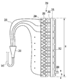
도 3은 본 발명의 일 실시 예에 따른 공기조화기의 열교환기 및 그 주변 구성을 보여주는 도면이다.FIG. 3 is a view illustrating a heat exchanger of the air conditioner according to an embodiment of the present invention and a peripheral structure thereof.
도 3에 도시된 바와 같이, 상기 실외 열교환기(200)에는, 복수의 열(列)과 단(段)을 이루는 냉매 배관(202)이 포함된다. 예를 들어, 상기 냉매 배관(202)은 가로 방향으로 3개의 열, 세로 방향으로 복수의 단을 이루도록 복수 개가 구비될 수 있으며, 복수의 냉매 배관(202)은 서로 이격되어 배치될 수 있다.As shown in FIG. 3, the
또한, 상기 복수의 냉매 배관(202)은 절곡하여 길게 연장될 수 있다. 예를 들어 도 3을 기준으로, 상기 복수의 냉매 배관(202)은 지면의 후방으로 연장된 후 다시 전방으로 연장되도록 구성될 수 있다. 이 경우, 상기 복수의 냉매 배관(202)은 'U'자 형상을 가질 수 있다.In addition, the plurality of
상기 실외 열교환기(200)에는, 상기 냉매 배관(202)을 지지하는 결합 플레이트(203)가 더 포함된다. 상기 결합 플레이트(203)는 복수 개가 제공되어, 절곡된 형상을 가지는 냉매 배관(202)의 일측 및 타측을 지지할 수 있다. 도 3에는, 상기 냉매 배관(202)의 일측을 지지하는 일 결합 플레이트(203)를 보여준다. 상기 결합 플레이트(203)는 상하 방향으로 길게 연장될 수 있다.The outdoor heat exchanger (200) further includes a coupling plate (203) for supporting the refrigerant pipe (202). A plurality of the
상기 실외 열교환기(200)에는, 상기 복수의 냉매 배관(202)의 단부에 결합되어, 일 냉매 배관(202)을 유동하는 냉매를 타 냉매 배관(202)으로 가이드 하는 리턴 배관(204)이 더 포함된다. 상기 리턴 배관(204)은 복수 개가 제공되며, 상기 결합 플레이트(203)에 결합될 수 있다.The
상기 실외 열교환기(200)에는, 냉매의 유동공간을 형성하는 헤더(205)가 더 포함된다. 상기 헤더(205)는, 공기 조화기(10)의 냉방 또는 난방운전 여부에 따라, 냉매를 상기 복수의 냉매배관(202)으로 분지하여 유입시키거나, 상기 복수의 냉매배관(202)에서 열교환 된 냉매를 합지하도록 구성될 수 있다. 상기 헤더(205)는 상기 결합 플레이트(203)의 연장방향에 대응하여, 상하 방향으로 길게 연장될 수 있다.The outdoor heat exchanger (200) further includes a header (205) forming a space for the refrigerant to flow. The
앞서 설명한 바와 같이, 상기 공기 조화기(10)에는, 상기 유동 전환부(130)로부터 상기 실외 열교환기(200)의 일 측에 연결되는 제 1 입출배관(300) 및 상기 실외 열교환기(200)의 타 측으로부터 상기 메인 팽창장치(260)로 연장되는 제 2 입출배관(145)이 포함된다.As described above, the
또한, 상기 공기 조화기(10)에는, 상기 제 2 입출배관(145)과 상기 실외 열교환기(200) 사이에 배치되는 분배기(210)가 포함된다.The
또한, 상기 분배기(210)와 상기 실외 열교환기(200)는 캐필러리 튜브(220)를 통해 연결된다. 상기 캐필러리 튜브(220)는 복수 개로 제공되며, 도 3에 도시된 바와 같이, 상기 캐플러리 튜브(220)는 상기 실외 열교환기(200)에 상하방향으로 각각 이격되어 결합된다.Also, the
상기 공기 조화기(10)의 냉방 운전시, 상기 실외 열교환기(200)는 응축기로 사용되며, 냉매는 상기 제 1 입출배관(300)을 통하여 상기 실외 열교환기(200)로 유입된다. 상기 실외 열교환기(200)에서 응축된 냉매는 상기 제 2 입출배관(145)을 통하여 상기 실외 열교환기(200)로부터 배출된다.The
또한, 상기 공기 조화기(10)의 난방 운전시, 상기 실외 열교환기(200)는 증발기로 사용되며, 냉매는 상기 제 2 입출배관(145)을 통하여 상기 실외 열교환기(200)로 유입된다. 상기 실외 열교환기(200)에서 증발된 냉매는 상기 제 1 입출배관(300)을 통하여 상기 실외 열교환기(200)로부터 배출된다.The
이하에서는, 상기에 설명한 구성을 참조하여, 공기 조화기의 냉방운전 및 난방운전시 공기 조화기(10)에서의 냉매 유동에 대하여 설명한다.Hereinafter, the refrigerant flow in the
공기 조화기가 냉방운전을 수행하는 경우, 상기 실외 열교환기(200)는 응축기로 기능하며 상기 실내 열교환기는 증발기로 가능한다. 자세하게는, 상기 실외 열교환기(200)는 상기 제 1 입출배관(300)을 통해 냉매가 유입되고 상기 제 2 입출배관(145)을 통해 냉매가 토출된다.When the air conditioner performs cooling operation, the
상기 제 1, 2 압축기(110, 112)에서 압축된 고온 고압의 냉매는 상기 제 1, 2 오일 분리기(120, 122)를 거치면서 오일이 분리되고 분리된 오일은 상기 회수유로(116)를 통하여 상기 제 1, 2 압축기(110, 112)로 복귀한다. 그리고, 오일이 분리된 냉매는 상기 유동 전환부(130)를 거쳐 제 1 입출배관(300)으로 유동하며, 상기 실외 열교환기(200)의 헤더(205)로 유입된다.The high-temperature and high-pressure refrigerant compressed by the first and
상기 헤더(205)로 유입된 냉매는 상기 복수의 냉매배관(202)으로 유입된다. 상기 냉매 배관(202)의 냉매는 열교환되는 과정에서 응축되며, 상기 캐필러리 튜브(220)로 유동될 수 있다.The refrigerant flowing into the
상기 복수의 캐필러리 튜브(220)의 냉매는 상기 분배기(210)로 유입되어 합지된 냉매는 상기 제 2 입출유로(145)로 유동된다. 계속하여, 상기 메인 팽창장치(260)를 통과하며, 상기 방열판(265) 및 과냉각 열교환기(270)를 거쳐 상기 실내기 측으로 유동할 수 있다.The refrigerant of the plurality of
냉매는 상기 실내기에서 팽창 및 증발한 후, 상기 유동 전환부(130) 및 기액 분리기(280)를 거쳐 다시 상기 제 1, 2 압축기(110, 120)로 흡입될 수 있다. 이러한 사이클이 반복될 수 있다.The refrigerant may expand and evaporate in the indoor unit and then be sucked into the first and
이와 같이, 공기 조화기(10)가 냉방 운전할 때, 냉매는 상기 실외 열교환기(200)에서 응축된 냉매는 상기 복수의 캐필러리 튜브(220)로 유동된다. 이때, 중력에 영향에 의해 상기 실외 열교환기(200)의 하부는 비교적 유량이 적어지고, 상기 실외 열교환기(200)의 상부는 비교적 유량이 클 수 있다.In this way, when the
이는 상기 실외 열교환기(200)의 하부는 중력의 영향을 비교적 크게 받기 때문이다. 자세하게는, 상기 실외 열교환기(200)의 하부에 위치된 냉매배관(200)에는 중력의 영향으로 액냉매가 쌓이게 되고, 상기 냉매배관(202) 내부의 유동저항이 커진다.This is because the lower part of the
그에 따라, 상기 실외 열교환기(200)의 상부로 많은 양의 냉매가 흐르게 되며, 상기 실외 열교환기(200)의 상부에 위치된 냉매배관(202)에서 많은 양의 냉매의 열교환이 이루어진다. 그에 따라, 냉매의 과냉도가 확보되지 않을 수 있다.Accordingly, a large amount of refrigerant flows to the upper portion of the
즉, 상기 실외 열교환기(200)의 하부에 위치된 냉매배관(200)은 냉매 유량이 적어 과도한 과냉각이 발생되며, 상기 실외 열교환기(200)의 상부에 위치된 냉매배관(202)은 냉매 유량이 많아 과냉도가 확보되지 않는다.That is, the
이와 같이, 상기 실외 열교환기(200)를 통과한 냉매의 유량 불균형 및 과냉도 편차가 커질 경우, 상기 실외 열교환기(200)의 열교환 능력은 저하될 수 있다.As described above, if the unevenness in flow rate and supercooling of the refrigerant passing through the
따라서, 본 실시 예에서는, 상기 제 1 입출배관(300)을 상기 실외 열교환기(200)의 하부에 설치한다. 상기 실외 열교환기(200)가 응축기로 기능할 때, 상기 제 1 입출배관(300)은 냉매 유입배관이 된다. 이하, 상기 제 1 입출배관(300)을 유입배관이라 하고, 상기 실외 열교환기(200)를 응축기라 한다.Accordingly, in the present embodiment, the first inlet /
앞서 설명한 바와 같이, 상기 응축기(200)에는, 복수의 열과 단을 이루는 복수의 냉매배관(202)이 포함된다. 도 3에서는, 예시적으로 상하방향으로 소정의 간격으로 이격되어 19열을 이루는 냉매배관(202)을 도시하였다.As described above, the
또한, 상기 응축기(200)에는, 상기 냉매배관(202)의 적어도 일 측에 결합되는 상기 헤더(205)가 포함된다. 도 3에 도시된 바와 같이, 상기 헤더(205)는 상하방향으로 연장되어 복수의 열을 이루는 상기 냉매배관(202)과 결합된다.In addition, the
이때, 상기 복수의 냉매배관(202)과 결합되기 위해, 상기 헤더(205)는 최상부 및 최하부에 위치된 냉매배관(202)보다 상부 및 하부로 더 연장될 수 있다. 즉, 상기 헤더(205)는 상기 응축기(200)의 최상단 및 최하단을 이루도록 상하방향으로 연장된다.At this time, in order to be coupled with the plurality of
그에 따라, 상기 헤더(205)의 상하방향길이를 상기 응축기(200)의 높이(H)라고 할 수 있다. 이때, 상기 헤더(205)의 하단, 즉, 응측기(200)의 하단에서 상기 유입배관(300)이 설치되는 높이까지의 상하방향 길이를 상기 헤더(205)에 결합되는 유입배관(300)의 설치높이(h)라 한다.Accordingly, the length of the
앞서 설명한 바와 같이, 상기 유입배관(300)은 상기 응축기(200)의 하부에 설치된다. 즉, 상기 유입배관(300)의 설치높이(h)는 상기 응축기(200)의 높이의 반 이하로 형성된다.(2h≤H)As described above, the
특히, 상기 유입배관(300)의 설치높이(h)는 상기 응축기(200)의 높이의 3분의 1이하로 형성되는 것이 바람직하다.(3h≤H)Particularly, it is preferable that the installation height h of the
상기 유입배관(300)이 상기 응축기(200)의 하부에 설치됨에 따라, 상기 유입배관(300)에서 상기 응축기(200)의 하부에 위치된 냉매배관(202) 간의 거리가 비교적 짧아진다. 그에 따라, 냉매의 압력손실이 감소되고, 상기 응축기(200)의 하부에 위치된 냉매배관(202)의 유량이 증가한다.The
또한, 상기 유입배관(300)에서 상기 응축기(200)의 상부에 위치된 냉매배관(202) 간의 거리가 비교적 길어진다. 그에 따라, 냉매의 압력손실이 증가되고, 상기 응축기(200)의 상부에 위치된 냉매배관(202)의 유량이 감소하여 과냉각을 확보할 수 있다.Further, the distance between the
도 3에서는, 상기 유입배관(300)이 복수 개로 분지되어 상기 헤더(205)에 각각 연결된 것을 도시하였다. 즉, 상기 유입배관(300)에는, 상기 헤더(205)와 각각 연결되는 분지관(302)이 포함된다. 상기 분지관(302)은 상하로 길게 연장되어 상기 헤더(205)에 결합된다.3, the
다만, 상기 분지관(302)은 냉매를 분배하기 위한 것으로 냉매의 유동통로 역할을 하고, 유입되는 냉매의 유입압과는 거의 무관하다. 즉, 상기 분지관(302)은 상기 헤더(205)를 보조하여 상기 냉매배관(202)으로 냉매를 분배하는 역할을 한다.However, the
또한, 상기 분지관(302)이 없이 상기 유입배관(300)은 상기 헤더(205)에 하나의 배관으로 결합될 수 있다. 즉, 상기 분지관(302)은 보조적인 기능을 하는 구성으로, 상기 유입배관(300)의 설치높이(h)를 정할 때는 냉매 전체가 유입되는 주 배관의 높이만을 고려한다.In addition, the
상기 유입배관(300)은 다양한 형태로 상기 응축기(200)의 하부에 설치될 수 있다. 이하, 다른 예에 대해 설명한다.The
도 4는 본 발명의 다른 실시 예에 따른 공기조화기의 열교환기 및 그 주변 구성을 보여주는 도면이다. 이상에서 설명한 내용과 동일한 부분은 그를 인용하고 설명을 생략한다.4 is a view showing a heat exchanger of the air conditioner according to another embodiment of the present invention and a peripheral structure thereof. The same parts as those described above are referred to and the description is omitted.
공기조화기에는, 상기 응축기(200)의 하부에 결합되는 유입배관(400)이 포함된다. 상기 유입배관(400)에는, 분지점(402)을 기준으로 분지된 제 1 유입배관(404) 및 제 2 유입배관(406)이 포함된다. 이때, 상기 제 1 유입배관(404) 및 상기 제 2 유입배관(406)의 설치높이는 상기 응축기(200)의 높이의 절반보다 작게 형성된다.The air conditioner includes an
또한, 상기 유입배관(400)에는, 상기 헤더(205)와 각각 연결되는 분지관(408)이 포함된다. 상기 분지관(408)은 보조적으로 냉매를 분배하기 위한 것으로, 상기 제 1 유입배관(404) 및 상기 제 2 유입배관(406)이 상기 헤더(205)에 직접 결합될 수 있다.The
냉매의 유동을 살펴보면, 상기 제 1 유입배관(404) 및 상기 제 2 유입배관(406)이 상기 응축기(200)의 하부에 설치되기 때문에, 하부에 위치된 상기 냉매배관(202)의 압력손실이 적어진다. 그에 따라, 중력에 따른 각 냉매배관(202) 사이의 유량 불균일이 보상될 수 있다.Since the first inflow pipe 404 and the
특히, 도 4에 도시된 바와 같이, 상기 제 1 유입배관(404) 및 상기 제 2 유입배관(406)과 각 분지관(408)은 수평하게 연결된다. 또한, 상기 냉매배관(202) 중 어느 하나와 상기 제 1 유입배관(404) 및 상기 제 2 유입배관(406)이 수평하게 연결된다. In particular, as shown in FIG. 4, the first inflow pipe 404 and the
따라서, 냉매가 하부에 위치된 상기 냉매배관(202)으로 바로 유입될 수 있다. 결과적으로, 하부에 위치된 상기 냉매배관(202)의 압력손실이 더 적어지고 유량이 상승된다.Therefore, the refrigerant can be directly introduced into the
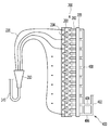
도 5는 본 발명의 또 다른 실시 예에 따른 공기조화기의 열교환기 및 그 주변 구성을 보여주는 도면이다.5 is a view showing a heat exchanger of the air conditioner according to another embodiment of the present invention and a peripheral structure thereof.
상기에서는 상기 실외 열교환기(200)가 응축기로 기능하고, 그에 따른 제 1 입출배관의 설치위치에 대해서 설명하였다. 본 발명의 공기조화기는 히트펌프로 사용될 수 있고, 상기 공기조화기는 난방운전을 수행할 수 있다.In the above description, the
공기 조화기가 난방운전을 수행하는 경우, 상기 제 1, 2 압축기(110, 112)에서 압축된 고온 고압의 냉매는 상기 제 1, 2 오일 분리기(120, 122)를 거치면서 오일이 분리되고 분리된 오일은 상기 회수유로(116)를 통하여 상기 제 1, 2 압축기(110, 112)로 복귀한다. 그리고, 오일이 분리된 냉매는 상기 유동 전환부(130)를 거쳐 실내기 측으로 유동한다.When the air conditioner performs the heating operation, the high-temperature and high-pressure refrigerant compressed by the first and
상기 실내기로 유입된 냉매는 실내 열교환기에서 응축되며, 응축된 냉매는 상기 과냉각 열교환기(270)로 유입된다. 이때, 일부의 냉매는 상기 과냉각 유로(273)로 분지되어 과냉각 팽창장치(275)에서 감압되어, 상기 과냉각 열교환기(270)로 유입될 수 있다.The refrigerant introduced into the indoor unit is condensed in the indoor heat exchanger, and the condensed refrigerant flows into the supercooling heat exchanger (270). At this time, a part of the refrigerant is branched into the
따라서, 상기 응축된 냉매와, 상기 과냉각 유로(273)를 유동한 냉매는 서로 열교환 되어, 상기 응축된 냉매가 과냉각 될 수 있다.Therefore, the condensed refrigerant and the refrigerant flowing through the
상기 과냉각 열교환기(270)를 통과한 과냉각 냉매는 상기 방열판(265)을 거치면서 상기 전장 유닛의 발열 부품을 냉각하고 상기 메인 팽창밸브(260)에서 감압될 수 있다.The supercooling refrigerant passing through the supercooling
감압된 냉매는 상기 제 2 입출배관(145) 및 분배기 배관(230)을 경유하여, 상기 분배기(210)로 유입된다. 그리고, 냉매는 상기 분배기(210)에서 분지되어, 상기 복수의 캐필러리 튜브(220)를 유동하며, 상기 복수의 냉매 배관(202)으로 유입된다. 냉매는 상기 복수의 냉매 배관(202)을 유동하는 과정에서 증발하며, 증발된 냉매는 상기 헤더(205)를 거쳐 제 1 입출배관(500)으로 배출될 수 있다.The decompressed refrigerant flows into the
또한, 상기 제 1 입출배관(500)으로 토출된 냉매는 상기 유동 전환부(130)를 거쳐 상기 기액 분리기(280)로 유입되고 분리된 기상 냉매가 상기 제 1, 2 압축기(110,112)로 흡입될 수 있다.The refrigerant discharged to the first inlet /
이때, 상기에서 설명한 바와 같이, 상기 제 1 입출배관(500)이 상기 실외 열교환기(200)의 하부에만 설치된다면, 냉매가 효율적으로 배출되지 못한다. 자세하게는, 냉매가 하부로 쏠리게되며 냉매 유량의 불균형이 발생된다.At this time, if the first inlet /
즉, 응축기의 경우, 중력의 영향으로 인해 상부로 냉매가 쏠리기 때문에, 상기 제 1 입출배관을 하부에 설치하여 유량의 균형을 도모하였다. 하지만, 증발기의 경우, 중력의 영향을 거의 받지 않기 때문에 상부로 냉매가 쏠리는 현상이 없어, 상기 제 1 입출배관이 하부에 설치되면 오히려 냉매 유량이 불균형이 발생되는 것이다.That is, in the case of the condenser, since the refrigerant is discharged to the upper part due to the effect of gravity, the first inlet / outlet pipe is installed at the lower part to balance the flow rate. However, in the case of the evaporator, since the refrigerant is hardly affected by gravity, there is no phenomenon that the refrigerant leans to the upper portion, and if the first inlet / outlet pipe is installed at the lower portion, the refrigerant flow rate is rather unbalanced.
따라서, 상기 제 1 입출배관(500)에는, 분배관(504), 상기 실외 열교환기(200)의 상부에 배치되는 상부배관(506) 및 하부에 배치되는 하부배관(502)이 포함된다. 상기 상부배관(506)에는, 냉매를 일방향으로 유동시키는 체크밸브(508)가 설치된다.Accordingly, the first inlet /
상기 체크밸브(506)에 의해, 상기 실외 열교환기(200)가 응축기로 사용되는 경우에는 상기 상부배관(506)으로 냉매가 유동되지 않는다. 그에 따라, 상기 하부배관(502)을 통해 냉매가 상기 실외 열교환기(200)로 유입되고, 목적으로 하는 유량의 균형을 도모할 수 있다.When the
또한, 상기 실외 열교환기(200)가 증발기로 사용되는 경우에는 상기 상부배관(506) 및 상기 하부배관(502)으로 냉매가 유동된다. 그에 따라, 냉매가 상기 실외 열교환기(20)의 상하부에서 각각 배출되어 유량의 균형을 도모할 수 있다.When the
이때, 상기 상부배관(506) 및 상기 하부배관(502)은 서로 대응하는 위치에 배치될 수 있다. 즉, 상기 실외 열교환기(200)의 상단 및 하단에서 동일한 거리만큼 떨어져서 배치될 수 있다.At this time, the
예를 들어, 상기 상부배관(506)은 상기 실외 열교환기(200) 높이의 3분의 2 지점에 배치되고, 상기 하부배관(502)은 상기 실외 열교환기(200) 높이의 3분 1지점에 배치될 수 있다.For example, the
Claims (10)
상기 응축기에는,
상하방향으로 이격되어 마련되는 복수의 냉매배관; 및
상기 복수의 냉매배관에 결합되도록, 상하방향으로 연장된 높이(H)를 갖는 헤더;가 포함되고,
상기 응축기로 냉매를 유입시키도록 마련된 유입배관은, 상기 헤더의 중심보다 하부에 설치되는 것을 특징으로 하는 공기조화기.An air conditioner comprising a compressor, a condenser, an expansion valve and an evaporator,
In the condenser,
A plurality of refrigerant pipes spaced apart in the vertical direction; And
And a header having a height (H) extending in a vertical direction so as to be coupled to the plurality of refrigerant pipes,
Wherein an inlet pipe provided to introduce the refrigerant into the condenser is installed below the center of the header.
상기 유입배관은,
상기 헤더의 하단에서 상기 헤더 높이의 3분의 1지점(H/3) 사이에 설치되는 것을 특징으로 하는 공기조화기.The method according to claim 1,
Wherein the inflow pipe comprises:
(H / 3) of the height of the header from the lower end of the header.
상기 유입배관은 상기 복수의 냉매배관 중 어느 하나와 수평하게 위치되도록 설치되는 것을 특징으로 하는 공기조화기.The method according to claim 1,
And the inflow pipe is installed to be positioned horizontally with any one of the plurality of refrigerant pipes.
상기 유입배관에는,
상기 복수의 냉매배관 중 어느 하나와 각각 수평하게 위치되는 제 1 유입배관 및 제 2 유입배관이 포함되는 것을 특징으로 하는 공기조화기.3. The method of claim 2,
In the inflow pipe,
And a first inlet pipe and a second inlet pipe positioned horizontally with any one of the plurality of refrigerant pipes.
상기 유입배관에는,
유입되는 냉매를 분배하도록, 상하로 길게 연장되어 상기 헤더에 각각 연결되는 분지관이 더 포함되는 것을 특징으로 하는 공기조화기.The method according to claim 1,
In the inflow pipe,
Further comprising a branch pipe extending upward and downward to distribute the introduced refrigerant and connected to the header, respectively.
상기 응축기 또는 상기 증발기로 기능하는 실외 열교환기;
상기 실외 열교환기의 일 측에 연결되는 제 1 입출배관; 및
상기 실외 열교환기의 타 측으로부터 상기 팽창밸브로 연장되는 제 2 입출배관;이 더 포함되는 공기조화기.The method according to claim 1,
An outdoor heat exchanger functioning as the condenser or the evaporator;
A first inlet / outlet pipe connected to one side of the outdoor heat exchanger; And
And a second inlet / outlet pipe extending from the other side of the outdoor heat exchanger to the expansion valve.
상기 제 1 입출배관에는,
상기 실외 열교환기의 상부에 결합되는 상부배관; 및
상기 실외 열교환기의 하부에 결합되는 하부배관;이 포함되는 것을 특징으로 하는 공기조화기.The method according to claim 6,
The first inlet /
An upper pipe connected to an upper portion of the outdoor heat exchanger; And
And a lower pipe coupled to a lower portion of the outdoor heat exchanger.
상기 상부배관에는 상기 실외 열교환기로 유입되는 냉매의 유동을 차단하는 체크밸브가 설치되는 것을 특징으로 하는 공기조화기.8. The method of claim 7,
Wherein the upper pipe is provided with a check valve for blocking the flow of the refrigerant flowing into the outdoor heat exchanger.
상기 상부배관 및 상기 하부배관은,
상기 실외 열교환기의 상단 및 하단으로부터 동일한 거리로 이격되어 배치되는 것을 특징으로 하는 공기조화기.8. The method of claim 7,
The upper pipe and the lower pipe,
Wherein the outdoor heat exchanger is disposed at an equal distance from the upper and lower ends of the outdoor heat exchanger.
상기 제 2 입출배관과 상기 실외 열교환기의 사이에는,
분배기 및 상기 분배기와 상기 실외 열교환기를 연결하는 복수의 캐필러리 튜브가 배치되는 것을 특징으로 하는 공기조화기.The method according to claim 6,
Between the second inlet / outlet pipe and the outdoor heat exchanger,
And a plurality of capillary tubes connecting the distributor and the outdoor heat exchanger are disposed.
Priority Applications (1)
| Application Number | Priority Date | Filing Date | Title |
|---|---|---|---|
| KR1020170025287A KR20180098763A (en) | 2017-02-27 | 2017-02-27 | Air conditioner |
Applications Claiming Priority (1)
| Application Number | Priority Date | Filing Date | Title |
|---|---|---|---|
| KR1020170025287A KR20180098763A (en) | 2017-02-27 | 2017-02-27 | Air conditioner |
Publications (1)
| Publication Number | Publication Date |
|---|---|
| KR20180098763A true KR20180098763A (en) | 2018-09-05 |
Family
ID=63594262
Family Applications (1)
| Application Number | Title | Priority Date | Filing Date |
|---|---|---|---|
| KR1020170025287A Withdrawn KR20180098763A (en) | 2017-02-27 | 2017-02-27 | Air conditioner |
Country Status (1)
| Country | Link |
|---|---|
| KR (1) | KR20180098763A (en) |
-
2017
- 2017-02-27 KR KR1020170025287A patent/KR20180098763A/en not_active Withdrawn
Similar Documents
| Publication | Publication Date | Title |
|---|---|---|
| KR101550549B1 (en) | An air conditioner | |
| US10156387B2 (en) | Outdoor device for an air conditioner | |
| KR101615445B1 (en) | An air conditioner | |
| CN104456722B (en) | Air conditioner | |
| US20160123645A1 (en) | Air conditioner and method of controlling the same | |
| KR101706865B1 (en) | Air conditioning system | |
| KR101694614B1 (en) | An air conditioner | |
| KR101550550B1 (en) | An air conditioner | |
| CN101592362A (en) | Air-conditioner | |
| JP2014122770A (en) | Heat exchanger | |
| JP2018138826A (en) | Air conditioner | |
| KR20180098763A (en) | Air conditioner | |
| KR20180096403A (en) | Air conditioner | |
| KR101626215B1 (en) | An air conditioner | |
| KR101644703B1 (en) | An air conditioner and Method of controlling the same | |
| KR20100036789A (en) | Air conditioner | |
| US20200200476A1 (en) | Heat exchanger | |
| KR20190055972A (en) | Air conditioner | |
| KR101626216B1 (en) | An air conditioner | |
| KR102100662B1 (en) | An air conditioner | |
| KR101630955B1 (en) | An air conditioner and Method of controlling the same | |
| WO2022255358A1 (en) | Air-conditioning device | |
| KR102760693B1 (en) | Air conditioner having a device for cooling a heat generating element using a mixed cooling heat exchanger | |
| KR101404554B1 (en) | an air conditioner with air-cooled heat exchange | |
| KR101425041B1 (en) | Outdoor heat exchanger |
Legal Events
| Date | Code | Title | Description |
|---|---|---|---|
| PA0109 | Patent application |
St.27 status event code: A-0-1-A10-A12-nap-PA0109 |
|
| R17-X000 | Change to representative recorded |
St.27 status event code: A-3-3-R10-R17-oth-X000 |
|
| PG1501 | Laying open of application |
St.27 status event code: A-1-1-Q10-Q12-nap-PG1501 |
|
| PN2301 | Change of applicant |
St.27 status event code: A-3-3-R10-R13-asn-PN2301 St.27 status event code: A-3-3-R10-R11-asn-PN2301 |
|
| P22-X000 | Classification modified |
St.27 status event code: A-2-2-P10-P22-nap-X000 |
|
| P22-X000 | Classification modified |
St.27 status event code: A-2-2-P10-P22-nap-X000 |
|
| A201 | Request for examination | ||
| PA0201 | Request for examination |
St.27 status event code: A-1-2-D10-D11-exm-PA0201 |
|
| P22-X000 | Classification modified |
St.27 status event code: A-2-2-P10-P22-nap-X000 |
|
| D13-X000 | Search requested |
St.27 status event code: A-1-2-D10-D13-srh-X000 |
|
| PC1202 | Submission of document of withdrawal before decision of registration |
St.27 status event code: N-1-6-B10-B11-nap-PC1202 |