KR20180098683A - Battery charging assembly and charging method for implementing such an assembly - Google Patents
Battery charging assembly and charging method for implementing such an assembly Download PDFInfo
- Publication number
- KR20180098683A KR20180098683A KR1020187024266A KR20187024266A KR20180098683A KR 20180098683 A KR20180098683 A KR 20180098683A KR 1020187024266 A KR1020187024266 A KR 1020187024266A KR 20187024266 A KR20187024266 A KR 20187024266A KR 20180098683 A KR20180098683 A KR 20180098683A
- Authority
- KR
- South Korea
- Prior art keywords
- connector
- electrical connector
- plug
- base
- connection
- Prior art date
- Legal status (The legal status is an assumption and is not a legal conclusion. Google has not performed a legal analysis and makes no representation as to the accuracy of the status listed.)
- Abandoned
Links
Images






Classifications
-
- H—ELECTRICITY
- H01—ELECTRIC ELEMENTS
- H01R—ELECTRICALLY-CONDUCTIVE CONNECTIONS; STRUCTURAL ASSOCIATIONS OF A PLURALITY OF MUTUALLY-INSULATED ELECTRICAL CONNECTING ELEMENTS; COUPLING DEVICES; CURRENT COLLECTORS
- H01R13/00—Details of coupling devices of the kinds covered by groups H01R12/70 or H01R24/00 - H01R33/00
- H01R13/62—Means for facilitating engagement or disengagement of coupling parts or for holding them in engagement
-
- H—ELECTRICITY
- H01—ELECTRIC ELEMENTS
- H01R—ELECTRICALLY-CONDUCTIVE CONNECTIONS; STRUCTURAL ASSOCIATIONS OF A PLURALITY OF MUTUALLY-INSULATED ELECTRICAL CONNECTING ELEMENTS; COUPLING DEVICES; CURRENT COLLECTORS
- H01R13/00—Details of coupling devices of the kinds covered by groups H01R12/70 or H01R24/00 - H01R33/00
- H01R13/62—Means for facilitating engagement or disengagement of coupling parts or for holding them in engagement
- H01R13/6205—Two-part coupling devices held in engagement by a magnet
-
- H—ELECTRICITY
- H01—ELECTRIC ELEMENTS
- H01R—ELECTRICALLY-CONDUCTIVE CONNECTIONS; STRUCTURAL ASSOCIATIONS OF A PLURALITY OF MUTUALLY-INSULATED ELECTRICAL CONNECTING ELEMENTS; COUPLING DEVICES; CURRENT COLLECTORS
- H01R13/00—Details of coupling devices of the kinds covered by groups H01R12/70 or H01R24/00 - H01R33/00
- H01R13/02—Contact members
- H01R13/22—Contacts for co-operating by abutting
- H01R13/24—Contacts for co-operating by abutting resilient; resiliently-mounted
- H01R13/2464—Contacts for co-operating by abutting resilient; resiliently-mounted characterized by the contact point
- H01R13/2478—Contacts for co-operating by abutting resilient; resiliently-mounted characterized by the contact point spherical
-
- H—ELECTRICITY
- H01—ELECTRIC ELEMENTS
- H01R—ELECTRICALLY-CONDUCTIVE CONNECTIONS; STRUCTURAL ASSOCIATIONS OF A PLURALITY OF MUTUALLY-INSULATED ELECTRICAL CONNECTING ELEMENTS; COUPLING DEVICES; CURRENT COLLECTORS
- H01R13/00—Details of coupling devices of the kinds covered by groups H01R12/70 or H01R24/00 - H01R33/00
- H01R13/66—Structural association with built-in electrical component
- H01R13/665—Structural association with built-in electrical component with built-in electronic circuit
- H01R13/6683—Structural association with built-in electrical component with built-in electronic circuit with built-in sensor
-
- H—ELECTRICITY
- H01—ELECTRIC ELEMENTS
- H01R—ELECTRICALLY-CONDUCTIVE CONNECTIONS; STRUCTURAL ASSOCIATIONS OF A PLURALITY OF MUTUALLY-INSULATED ELECTRICAL CONNECTING ELEMENTS; COUPLING DEVICES; CURRENT COLLECTORS
- H01R43/00—Apparatus or processes specially adapted for manufacturing, assembling, maintaining, or repairing of line connectors or current collectors or for joining electric conductors
- H01R43/26—Apparatus or processes specially adapted for manufacturing, assembling, maintaining, or repairing of line connectors or current collectors or for joining electric conductors for engaging or disengaging the two parts of a coupling device
-
- H—ELECTRICITY
- H02—GENERATION; CONVERSION OR DISTRIBUTION OF ELECTRIC POWER
- H02J—ELECTRIC POWER NETWORKS; CIRCUIT ARRANGEMENTS OR SYSTEMS FOR SUPPLYING OR DISTRIBUTING ELECTRIC POWER; SYSTEMS FOR STORING ELECTRIC ENERGY
- H02J7/00—Circuit arrangements for charging or discharging batteries or for supplying loads from batteries
- H02J7/70—Circuit arrangements for charging or discharging batteries or for supplying loads from batteries characterised by the mechanical construction
- H02J7/751—Circuit arrangements for charging or discharging batteries or for supplying loads from batteries characterised by the mechanical construction concerning the insertion or the connection of the batteries
-
- Y—GENERAL TAGGING OF NEW TECHNOLOGICAL DEVELOPMENTS; GENERAL TAGGING OF CROSS-SECTIONAL TECHNOLOGIES SPANNING OVER SEVERAL SECTIONS OF THE IPC; TECHNICAL SUBJECTS COVERED BY FORMER USPC CROSS-REFERENCE ART COLLECTIONS [XRACs] AND DIGESTS
- Y02—TECHNOLOGIES OR APPLICATIONS FOR MITIGATION OR ADAPTATION AGAINST CLIMATE CHANGE
- Y02T—CLIMATE CHANGE MITIGATION TECHNOLOGIES RELATED TO TRANSPORTATION
- Y02T10/00—Road transport of goods or passengers
- Y02T10/60—Other road transportation technologies with climate change mitigation effect
- Y02T10/70—Energy storage systems for electromobility, e.g. batteries
-
- Y—GENERAL TAGGING OF NEW TECHNOLOGICAL DEVELOPMENTS; GENERAL TAGGING OF CROSS-SECTIONAL TECHNOLOGIES SPANNING OVER SEVERAL SECTIONS OF THE IPC; TECHNICAL SUBJECTS COVERED BY FORMER USPC CROSS-REFERENCE ART COLLECTIONS [XRACs] AND DIGESTS
- Y02—TECHNOLOGIES OR APPLICATIONS FOR MITIGATION OR ADAPTATION AGAINST CLIMATE CHANGE
- Y02T—CLIMATE CHANGE MITIGATION TECHNOLOGIES RELATED TO TRANSPORTATION
- Y02T10/00—Road transport of goods or passengers
- Y02T10/60—Other road transportation technologies with climate change mitigation effect
- Y02T10/7072—Electromobility specific charging systems or methods for batteries, ultracapacitors, supercapacitors or double-layer capacitors
-
- Y—GENERAL TAGGING OF NEW TECHNOLOGICAL DEVELOPMENTS; GENERAL TAGGING OF CROSS-SECTIONAL TECHNOLOGIES SPANNING OVER SEVERAL SECTIONS OF THE IPC; TECHNICAL SUBJECTS COVERED BY FORMER USPC CROSS-REFERENCE ART COLLECTIONS [XRACs] AND DIGESTS
- Y02—TECHNOLOGIES OR APPLICATIONS FOR MITIGATION OR ADAPTATION AGAINST CLIMATE CHANGE
- Y02T—CLIMATE CHANGE MITIGATION TECHNOLOGIES RELATED TO TRANSPORTATION
- Y02T90/00—Enabling technologies or technologies with a potential or indirect contribution to GHG emissions mitigation
- Y02T90/10—Technologies relating to charging of electric vehicles
- Y02T90/14—Plug-in electric vehicles
Landscapes
- Engineering & Computer Science (AREA)
- Manufacturing & Machinery (AREA)
- Microelectronics & Electronic Packaging (AREA)
- Charge And Discharge Circuits For Batteries Or The Like (AREA)
- Details Of Connecting Devices For Male And Female Coupling (AREA)
- Manufacturing Of Electrical Connectors (AREA)
- Secondary Cells (AREA)
Abstract
본 발명은 배터리를 포함하는 물체와 상기 배터리를 충전하기 위한 플러그(10) - 상기 플러그(10)는 전원에 연결될 수 있음 - 를 포함하는 충전 조립체와 관련된다. 본 발명에 따르면, 물체는 플러그(10)를 수용하기에 적합하고, 제1 전기 커넥터와 베이스에 대해 플러그(10)를 위치설정하기에 적합한 제1 자기 커넥터를 포함하는 베이스를 포함한다. 플러그(10)는 베이스의 표면에 상보적인 형태를 갖는 접속 표면, 제1 전기 커넥터와 접속하여 접속 표면이 베이스의 표면 상에 위치설정될 때 제1 전기 커넥터와 제2 전기 커넥터 간 전기적 접속이 가능해지도록 위치설정되는 제2 전기 커넥터(12), 접속 표면에 근접하게 위치설정되어 제1 자기 커넥터를 끌어당겨 배터리 충전 동안 제1 전기 커넥터와 제2 전기 커넥터가 정렬되고 전기적 접속이 유지될 수 있도록 하는 제2 자기 커넥터를 포함한다. 제1 전기 커넥터와 제2 전기 커넥터 중 하나는 표면 커넥터이고 제1 전기 커넥터와 제2 전기 커넥터 중 다른 하나는 점 커넥터이며, 베이스 상에서의 접속 표면의 복수의 개별적인 배향에 대해 표면 커넥터에 놓이도록 위치설정된다.The invention relates to a charging assembly comprising an object comprising a battery and a plug (10) for charging the battery, the plug (10) being connectable to a power source. According to the present invention, an object is suitable for receiving a plug 10 and includes a base including a first electrical connector and a first magnetic connector adapted to position the plug 10 relative to the base. The plug 10 has a connection surface having a complementary shape to the surface of the base, an electrical connection between the first electrical connector and the second electrical connector when the connection surface is positioned on the surface of the base in connection with the first electrical connector A second electrical connector positioned proximate to the connection surface to pull the first magnetic connector so that the first electrical connector and the second electrical connector are aligned and the electrical connection is maintained during battery charging And a second magnetic connector. One of the first electrical connector and the second electrical connector is a surface connector and the other of the first electrical connector and the second electrical connector is a point connector and is positioned so as to be positioned on the surface connector for a plurality of individual orientations of the connection surface on the base, Respectively.
Description
본 발명은 물체와 상기 물체의 충전식 배터리를 충전하기 위한 플러그를 포함하는 충전 조립체와 관련된다. 본 발명은 배터리의 충전을 필요로 하는 임의의 분야, 가령, 전화기 또는 로봇에 적용될 수 있다. 본 발명은 또한 이러한 조립체를 구현하는 충전식 배터리 충전 방법과도 관련된다. The invention relates to a charging assembly comprising an object and a plug for charging the rechargeable battery of the object. The present invention can be applied to any field requiring charging of a battery, for example, a telephone or a robot. The present invention also relates to a rechargeable battery charging method embodying such an assembly.
배터리로 동작하는 물체는, 특정 시점에서, 자신의 배터리를 충전할 필요가 있다. 이때 이 물체는 자신의 배터리가 충전될 수 있게 하는 특정 장치를 통해 전원에 연결된다.The battery-operated object needs to charge its battery at a certain point in time. This object is then connected to the power source through a specific device that allows its battery to be charged.
그럼에도, 물체와 관련된 충전 장치의 위치설정 불량, 또는 물체의 커넥터와 장치 간 접촉 물량 때문에 물체를 충전 장치로 연결하는 데 어려움이 있을 수 있다. 또한 물체가 충전 장치에 연결될 때, 물체의 전기 커넥터와 충전 장치 간에 전기 아크가 발생하며, 이는 물체 및/또는 장치에 손상을 입힐 수 있다.Nevertheless, there may be difficulties in connecting the object to the charging device due to poor positioning of the charging device associated with the object, or due to the amount of contact between the connector and the device of the object. Also, when an object is connected to a charging device, an electric arc arises between the electrical connector of the object and the charging device, which can damage the object and / or the device.
물체는 또한 이동체, 더 구체적으로 전동 이동체일 수 있다, 즉, 스스로 움직일 수 있다. 이동체는 하나 이상의 축전 배터리, 또는 더 일반적으로 하나 이상의 배터리에 의해 전기를 공급받을 수 있다. 이는 원하는 용량의 전기 전압 발생기를 만들도록 서로 연결된 전기 저장 배터리의 세트와 관련된다. 배터리의 첫 번째 목표는 이동체의 운동에 필요한 전류 강도 및 전압을 공급하는 것이다. 배터리는 또한 이동체에 내장된 전자 기어에 전력을 공급하도록 사용될 수 있다.The object may also be a moving object, more specifically an electric moving object, i.e. it can move on its own. The moving object may be powered by one or more accumulator batteries, or more generally by one or more batteries. This relates to a set of electrical storage batteries connected together to create a desired capacity electrical voltage generator. The first goal of the battery is to supply the current intensity and voltage needed for the motion of the moving object. The battery can also be used to power an electronic gear embedded in the mobile body.
특정 시점에서, 물체 또는 이동체의 배터리를 충전하는 것이 필요하다. 일반적으로, 배터리로 작동하는 이동체는 배터리가 충전되어 있는 동안 이동할 수 있고 충전량이 끝나면 움직이지 않게 된다. 이때 예를 들면 이동체를 배터리 충전 베이스 상으로 놓기 위한 외부 개입이 필요하다. 앞서 언급된 것과 동일한 문제, 즉 이동체와 베이스 간 연결의 어려움 및/또는 바람직하지 않은 전기 아크의 발생이라는 문제가 발생할 수 있다.At some point, it is necessary to charge the battery of the object or the moving object. Generally, a battery-powered moving object can move while the battery is being charged and will not move when the charge is over. At this time, for example, external intervention is required to place the mobile body on the battery charging base. The same problems as those mentioned above may arise, that is, the difficulty of connection between the moving body and the base and / or the generation of an undesirable electric arc.
또한, 충전 동안, 베이스 상에서 위치를 유지해야 하기 때문에 이동체는 배터리가 충전될 동안 비활성화된다. 물체의 경우, 충전 중일 때, 충전 베이스 상에 유지되어야 하며 이는 이동을 억제한다. Further, during charging, the moving body is inactivated while the battery is being charged, since it must maintain its position on the base. In the case of an object, it must be kept on the charging base when charging, which inhibits movement.
본 발명의 목적은 배터리를 갖는 물체 - 상기 물체는 비이동형 물체 또는 이동형 물체일 수 있음 - 와, 상기 물체의 배터리를 충전하기 위한 플러그 - 상기 플러그는 전원에 연결될 수 있음 - 를 포함하는 충전 조립체와, 이러한 조립체를 구현하는 방법을 제안하여, 플러그와 물체 간 단순화된 연결에 의해 임의의 물체가 충전될 수 있게 함으로써, 앞서 언급된 모든 또는 일부 문제를 극복하는 것이다. 본 발명에 따르는 충전 조립체는 배터리가 충전 중일 때에도 이동체가 이동할 수 있게 하도록 구성된다. It is an object of the invention to provide a charging assembly comprising a body having a battery, the body being a non-moving object or a mobile object, and a plug for charging the battery of the object, the plug being connectable to a power source, , Suggesting a method of implementing such an assembly and overcoming all or some of the problems mentioned above by allowing any object to be charged by a simplified connection between the plug and the object. A charging assembly in accordance with the present invention is configured to allow a moving object to move even when the battery is being charged.
이러한 목적을 위한, 본 발명의 주제는 충전 조립체이며, 상기 충전 조립체는 배터리를 포함하는 물체와, 상기 배터리를 충전하기 위한 플러그를 포함하고, 상기 플러그는 전원에 연결될 수 있으며, 물체는, 플러그를 수용할 수 있는 베이스를 포함하며, 상기 베이스는 제1 전기 커넥터와, 플러그를 베이스에 대해 위치설정할 수 있는 제1 자기 커넥터를 포함하며, 상기 플러그는, 베이스의 표면에 상보적인 형태의 접속 표면과, 접속 표면이 베이스의 표면 상에 위치될 때 제1 전기 커넥터와 제2 전기 커넥터 간 전기적 접속을 가능하게 하도록 제1 전기 커넥터와 접속하도록 배열된 제2 전기 커넥터와, 상기 접속 표면에 근접하게 위치설정되며, 제1 자기 커넥터를 끌어당겨, 배터리가 충전되는 동안 제1 전기 커넥터와 제2 전기 커넥터의 정렬 및 전기적 접속이 안정화되게 하는 제2 자기 커넥터를 포함하고, 제1 전기 커넥터와 제2 전기 커넥터 중 하나는 표면 커넥터이고 제1 전기 커넥터와 제2 전기 커넥터 중 다른 하나는, 베이스 상에서의 접속 표면의 복수의 개별적인 배향에 대해, 상기 표면 커넥터에 대해 배치되도록 구성된 스팟 커넥터(spot connector)이며, 상기 플러그는 전기 케이블에 의해 전원에 연결될 수 있으며, 상기 플러그는, 제2 전기 커넥터와 제2 자기 커넥터가 고정된 몸체, 상기 몸체에 대해 회전 이동하는 이동 부분 - 상기 케이블은 상기 이동 부분의 회전을 가능하게 하는 가요성 와이어에 의해 상기 이동 부분에 고정되며 커넥터에 전기적으로 링크됨 - 을 포함한다. For this purpose, the subject of the present invention is a charging assembly, the charging assembly comprising an object comprising a battery and a plug for charging the battery, the plug being connectable to a power source, The base comprising a first electrical connector and a first magnetic connector capable of positioning the plug relative to the base, the plug comprising a connection surface in the form of a complementary shape to the surface of the base, A second electrical connector arranged to connect with a first electrical connector to enable electrical connection between the first electrical connector and the second electrical connector when the connecting surface is located on the surface of the base, And the first magnetic connector is pulled so that the alignment of the first electrical connector and the second electrical connector and the electrical connection Wherein one of the first electrical connector and the second electrical connector is a surface connector and the other of the first electrical connector and the second electrical connector comprises a plurality of individual orientations Wherein the plug is connected to a power source by means of an electric cable, the plug comprising: a body having a second electrical connector and a second magnetic connector fixedly mounted thereon, A moving portion that rotates relative to the body, the cable being secured to the moving portion by a flexible wire enabling rotation of the moving portion and electrically linked to the connector.
바람직하게는, 표면 커넥터는 원형 형태를 가진다.Preferably, the surface connector has a circular shape.
바람직하게는, 충전 조립체는 접속 표면과 베이스의 표면 간 접속을 검출할 수 있는 존재 검출기를 더 포함한다. Preferably, the filling assembly further comprises a presence detector capable of detecting a connection between the connection surface and the surface of the base.
하나의 실시예에 따라, 스팟 커넥터가 접속 표면과 제1 접속점을 형성할 때, 제1 전기 커넥터와 제2 전기 커넥터 중 하나가 상기 제1 접속점을 통과하여 접속 표면에 실질적으로 직각인 제1 축을 따라 상기 접속 표면에 대해 병진 운동하는 자유도를 갖도록 상기 조립체가 구성된다. According to one embodiment, when the spot connector forms a first connection point with the connection surface, one of the first and second electrical connectors passes through the first connection point to form a first axis substantially perpendicular to the connection surface The assembly is configured to have a degree of freedom to translate relative to the connection surface.
하나의 실시예에 따라, 스팟 커넥터가 접속 표면과 제1 접속점을 형성할 때, 제1 접속점을 통과하여 접속 표면에 실질적으로 직각인 제1 축 상에 힘을 발생시키도록 조립체가 구성된다. According to one embodiment, when the spot connector forms a first connection point with a connection surface, the assembly is configured to generate a force on a first axis passing through the first connection point and substantially perpendicular to the connection surface.
바람직하게는, 베이스는 제1 극과 제1 반경을 가지며 구체형 캡에 상보적 형태를 갖는 공동을 포함하며, 플러그는 제2 극과 상기 제1 반경과 실질적으로 동일한 제2 반경을 갖는 구체형 캡의 형태를 가지며, 표면 커넥터는 제1 극이 중심인 원 상에 센터링된다. Preferably, the base includes a cavity having a first pole and a first radius and having a complementary shape to the spherical cap, the plug having a second pole and a spherical shape having a second radius substantially equal to the first radius, And the surface connector is centered on a circle centered on the first pole.
바람직하게는, 상기 플러그는 플러그의 제2 극 상에 위치설정되는 제3 전기 커넥터를 포함하며, 상기 베이스는, 베이스의 제1 극 상에 위치설정되며, 접속 표면이 베이스 상에 위치설정될 때 제3 전기 커넥터와 접속하여 제3 전기 커넥터와 제4 전기 커넥터 간 전기적 접속을 가능하게 하는 제4 전기 커넥터를 포함한다. Preferably, the plug includes a third electrical connector positioned on a second pole of the plug, the base being positioned on a first pole of the base, and when the connection surface is positioned on the base And a fourth electrical connector connected to the third electrical connector to enable electrical connection between the third electrical connector and the fourth electrical connector.
바람직하게는, 전원은 양극과 음극을 갖는 DC 전압원이며, 제3 전기 커넥터는 전원의 음극에 연결되고, 제2 전기 커넥터는 전원의 양극에 연결된다. Preferably, the power source is a DC voltage source having an anode and a cathode, the third electrical connector is connected to the cathode of the power source, and the second electrical connector is connected to the anode of the power source.
바람직하게는, 접속 표면은 제1 축에 실질적으로 직각인 제2 축을 따라 병진 운동하는 자유도를 가지며, 접속 표면이 베이스 상에 위치설정될 때 제2 전기 커넥터와 제1 전기 커넥터의 접속을 보조하도록 구성된 가요성 구역(flexible zone)을 포함한다. Preferably, the connecting surface has a degree of freedom to translate along a second axis substantially perpendicular to the first axis and is adapted to assist in connection of the second electrical connector and the first electrical connector when the connecting surface is positioned on the base And a flexible zone configured.
본 발명의 또 다른 주제는 이러한 충전 조립체를 구현하는 충전 방법이며, 상기 방법은 접속 표면을 베이스의 표면 상에 위치설정하는 단계와, 제1 전기 커넥터와 제2 전기 커넥터를 정렬하는 단계를 포함한다. A further subject matter of the present invention is a charging method for implementing such a charging assembly, the method comprising positioning a connection surface on a surface of a base, and aligning the first electrical connector and the second electrical connector .
바람직하게는, 상기 방법은 충전 활성화 단계를 더 포함하며, 상기 충전 활성화 단계는 존재 검출기에 의해 물체 상에서의 플러그의 존재를 검증하는 단계, 배터리의 단자에서의 전압을 측정하고 측정된 전압을 최소 전압 값과 최대 전압 값에 비교하는 단계, 배터리의 내부 저항을 측정하고 측정된 저항을 최소 저항 값 및 최대 저항 값에 비교하는 단계를 포함한다. Advantageously, the method further comprises a charge activation step, wherein the charge activation step comprises verifying the presence of the plug on the object by the presence detector, measuring the voltage at the terminals of the battery, Value and a maximum voltage value, measuring the internal resistance of the battery, and comparing the measured resistance to a minimum resistance value and a maximum resistance value.
바람직하게는, 상기 방법은 충전 종료 단계를 포함하며, 상기 충전 종료 단계는 순서대로 수행되는 제2 전기 커넥터와 제1 전기 커넥터를 분리하는 단계와, 제4 전기 커넥터와 제3 전기 커넥터를 분리하는 단계를 포함한다. Preferably, the method includes a charging termination step, wherein the charging termination step comprises separating a second electrical connector and a first electrical connector, which are performed in sequence, and separating the fourth electrical connector and the third electrical connector .
상기 물체는 충전될 수 있는 배터리를 갖는 임의의 물체일 수 있다. 이는 물체, 가령, 전화기, 장난감 등일 수 있으며, 이동 물체, 가령, 자신의 수단에 의해 이동할 수 있는 전동 이동체, 가령, 로봇일 수 있다. The object may be any object having a battery that can be charged. This can be an object, such as a telephone, a toy, or the like, and can be a moving object, for example, an electric moving object that can be moved by its own means, such as a robot.
예시로 제공된 실시예의 상세한 설명과 다음의 도면을 읽음으로써 본 발명이 이해되고 그 밖의 다른 이점들이 명백해질 것이다.
도 1은 본 발명에 따르는 충전 조립체의 플러그를 개략적으로 나타낸다.
도 2는 본 발명에 따르는 충전 조립체의 베이스의 표면의 예시를 나타낸다.
도 3은 본 발명에 따르는 충전 조립체의 플러그의 접속 표면의 정면도를 개략적으로 나타낸다.
도 4는 본 발명에 따르는 도 3에 나타난 충전 조립체의 플러그를 수용할 수 있는 베이스의 표면의 정면도를 나타낸다.
도 5는 본 발명에 따르는 충전 조립체의 플러그의 횡단면도를 개략적으로 나타낸다.
도 6은 본 발명에 따르는 충전 조립체의 플러그의 횡단면도를 개략적으로 나타낸다.
도 7은 본 발명에 따르는 충전 조립체의 플러그의 횡단면도를 개략적으로 나타내고, 플러그의 접속 표면은 물체의 베이스의 표면과 접속한다.
도 8은 본 발명에 따르는 충전 조립체의 물체의 횡단면도를 개략적으로 나타낸다.
도 9는 본 발명에 따르는 충전 조립체를 구현하는 충전 방법의 단계를 도시한다.
도 10은 본 발명에 따르는 충전 조립체의 플러그를 이용해 충전되도록 구성된 휴머노이드 로봇을 나타낸다. BRIEF DESCRIPTION OF THE DRAWINGS The present invention will be understood and other advantages will become apparent upon reading the following detailed description of the embodiments given by way of illustration and the following drawings.
1 schematically shows a plug of a charging assembly according to the invention.
Figure 2 shows an illustration of the surface of the base of the filling assembly according to the invention.
Figure 3 schematically shows a front view of a connection surface of a plug of a filling assembly according to the invention.
Figure 4 shows a front view of the surface of a base capable of receiving a plug of the filling assembly shown in Figure 3 according to the present invention.
Figure 5 schematically shows a cross-sectional view of a plug of a charging assembly according to the invention.
Figure 6 schematically shows a cross-sectional view of a plug of a filling assembly according to the invention.
Figure 7 schematically shows a cross-sectional view of a plug of a filling assembly according to the invention, the connecting surface of the plug being connected to the surface of the base of the object;
Figure 8 schematically shows a cross-sectional view of an object of the filling assembly according to the invention.
Figure 9 shows the steps of a filling method embodying a filling assembly according to the present invention.
Figure 10 shows a humanoid robot configured to be charged using a plug of a charging assembly according to the present invention.
간결성을 위해, 상이한 도면에서 동일한 요소는 동일한 도면부호를 가질 것이다. For the sake of brevity, the same elements in different drawings will have the same reference numerals.
이하에서 본 발명은 물체의 예시를 들어 기재된다. 그러나 본 발명은 이동형이든 비이동형이든 그 밖의 다른 임의의 물체에 적용될 수 있는데, 즉, 배터리를 갖는 임의의 이동체가 충전될 수 있다.Hereinafter, the present invention will be described by way of example of an object. However, the present invention can be applied to any other object, whether mobile or non-mobile, i.e., any mobile with a battery can be charged.
도 1은 본 발명에 따르는 충전 조립체(100)의 플러그(10)를 개략적으로 나타낸다. Figure 1 schematically illustrates a
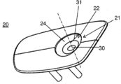
도 2는 본 발명에 따르는 충전 조립체(100)의 물체(20)의 표면의 예시를 나타낸다. Figure 2 illustrates an example of the surface of an
충전 조립체(100)는 배터리를 포함하는 물체(20)와 상기 배터리를 충전하도록 구성된 플러그(10)를 포함한다. 상기 플러그(10)는 전원에 연결될 수 있다.The
도 2에서 도시된 바와 같이, 물체(20)는 플러그(10)를 수용할 수 있는 베이스(21)를 포함한다. 상기 베이스(21)는 베이스(21)에 대해 플러그(10)를 위치시킬 수 있는 제1 전기 커넥터(22) 및 제1 자기 커넥터(23)(도 2에 도시되지 않음)를 포함한다. As shown in FIG. 2, the
본 출원에서, 커넥터는, 전기 커넥터이든 자기 커넥터이든, 접속 요소로 이해되어야 하는데, 즉, 점 또는 표면 접속 요소로서, 각각 전기 또는 자기적 연결을 만들 수 있다. In the present application, a connector, whether an electrical connector or a magnetic connector, is to be understood as a connecting element, that is to say, as a point or surface connecting element, it is possible to make electrical or magnetic connections, respectively.
도 1에 도시된 바와 같이, 플러그(10)는 베이스(21)의 표면과 상보적인 접속 표면(11)을 포함한다. 상기 플러그는 제1 전기 커넥터(22)와 접속하도록 배열되는 제2 전기 커넥터(12)를 포함함으로써, 접속 표면(11)이 베이스(21)의 표면 상에 위치할 때 제1 전기 커넥터와 제2 전기 커넥터(22, 12) 간 전기적 접속이 가능해진다. 플러그(10)는 접속 표면(11)에 근접하게 위치하는 제2 자기 커넥터(13)(도 1에 도시되지 않음)를 포함하여, 제1 자기 커넥터(23)를 끌어당겨, 제1 및 제2 전기 커넥터(22, 12)의 정렬을 가능하게 하고 배터리가 충전 중인 동안 전기적 접속을 안정화할 수 있다. As shown in Figure 1, the
본 발명에 따라, 제1 및 제2 전기 커넥터(22, 12) 중 하나는 표면 커넥터(surface connector)(24)이고 제1 및 제2 전기 커넥터(22, 12) 중 다른 하나는 베이스(21) 상에서의 접속 표면(11)의 몇 가지 개별적인 배열에 대해, 표면 커넥터(24)에 대항하여 배치되도록 배열된 스팟 커넥터(spot connector)(14)이다. One of the first and second
접속 표면(11)은 제1 전기 커넥터(22)를 포함하는 베이스(21)의 표면을 상보하는 형태를 갖기 때문에, 배터리가 충전 중일 때 두 표면은 서로 접촉한다. 2개의 자기 커넥터(23, 13)가 각각 베이스(21)의 표면 및 접속 표면(11)에 근접하여 위치한다. 제1 자기 커넥터를 끌어당기기 위해, 플러그(11)를 베이스(21)까지 가져감으로써 2개의 자기 커넥터(23, 13)가 서로에 대한 인력을 발휘한다. 2개의 자기 커넥터(23, 13)가 서로에 대해 인력을 발휘할 때 2개의 자기 커넥터(23, 13)는, 2개의 전기 커넥터(22, 12)가 서로에 대해 접촉하는 방식으로 위치한다.Since the connecting
본 발명은 플러그(10) 내 하나의 자기 커넥터와 베이스(21) 내 하나의 자기 커넥터와 관련하여 기재되지만, 플러그(10)가 복수의 자기 커넥터(13)를 포함하고 베이스(21)가 복수의 자기 커넥터(23)를 포함하는 구성 역시 포함하며, 바람직하게는 플러그와 자기 커넥터의 수가 동일하지만, 반드시 그럴 필요는 없다.Although the present invention is described with reference to one magnetic connector in a
자기 커넥터(13, 23)에 의해 전기 커넥터(12, 22)의 서로에 대한 최적의 전기적 접속을 유지하는 것이 가능하다. 이들은 또한 편광자(polarizer) 역할을 하며 플러그(10)와 베이스(21) 간 자기-정렬을 보장한다.It is possible to maintain optimal electrical connection of the
하나의 바람직한 실시예에 따르면, 표면 커넥터(24)는 원형 형태를 가진다.According to one preferred embodiment, the
덧붙여, 전기 커넥터(22, 12) 중 하나가 표면 커넥터(24)이고 나머지 하나가 표면 커넥터(24)와 접속하도록 배열된 스팟 커넥터(14)이며, 하나 또는 복수의 자기 커넥터가 플러그(10) 및 베이스(21) 각각에 분산되어 있기 때문에, 베이스(21)에 대한 플러그(10)의 접속 표면(11)의 배향과 무관하게, 플러그(10)와 베이스(21) 간 전기적 접속을 확립하는 것이 가능하며, 베이스(21)의 표면에 대한 접속 표면(11)의 몇 가지 개별 배향을 위해 그렇게 한다. 예를 들어, 도 2에 도시된 바와 같은 고리형 표면 커넥터(24)의 경우, 베이스(21) 상에서의 플러그(10)의 접속 표면(11)의 배향에 무관하게, 스팟 커넥터(14)는 표면 커넥터(24)와 접속될 수 있다. 다시 말하면, 접속 표면(11)은 베이스(21)의 표면에 대해 약 360° 회전하는 임의의 위치를 추정할 수 있다. 고리의 중앙을 관통하며 고리의 둘레를 포함하는 평면에 실질적으로 직각인 축을 고려하면, 플러그(10)와 이의 접속 표면(11)은 초기 위치를 추정하고 베이스(21)의 표면에 대해 상기 축을 중심으로 하는 0 내지 360°의 임의의 각도의 회전까지 수행할 수 있고, 어느 각도라도, 스팟 커넥터(14)는 표면 커넥터(24)와 접속한다. 이는 또한 표면 커넥터(24)가 다각형, 가령, 사각형인 경우에도 적용된다. 베이스(21)에 대한 접속 표면(11)의 몇 가지 개별 배향에 대해, 동일한 스팟 커넥터(14)가 상기 표면 커넥터(24)와 전기적 접속을 형성할 수 있다. In addition, the
이 구성은 플러그(10)를 베이스(21) 상에 배치할 때 물체(20)에 플러그(10)를 가져가는 단계에서 바람직한데, 왜냐하면 두 전기 커넥터(12, 22) 간 접속을 만들기 위해 베이스(21)의 표면에 대한 플러그(10)의 접속 표면의 특정 정렬을 관측할 필요가 없기 때문이며, 또한 배터리가 충전 중일 때 바람직한데, 왜냐하면 두 전기 커넥터(12, 22) 간 접속이 이뤄진 후, 두 전기 커넥터(12, 22) 간 전기적 접속을 어떠한 식으로도 끊지 않으면서 플러그는 작은 회전 운동력을 유지할 수 있기 때문이다. 실제로, 전기적 접속이 확립되면, 외부 동작이 플러그(10)를 이동시켜 베이스(21)의 표면 위에서 가볍게 미끄러트릴 수 있다. 표면 커넥터(24)와 스팟 커넥터(14) 간 접속과 허용 가능한 수준의 회전 덕분에, 전기적 접속이 유지될 수 있다.This configuration is preferable in the step of bringing the
표면 커넥터(24)는 원형 형태를 가질 수 있다. 도 2에서, 이는 고리(ring)이다. 본 발명은 또한 원, 즉, 매우 작은 두께의 고리를 형성하는 표면 커넥터(24)에 적용된다. 본 발명은 또한 원의 일부분 또는 고리의 일부분인 표면 커넥터(24)에 적용된다. 이 경우, 앞서 언급된 각도가 더는 0 내지 360°에 있지 않는다. 예를 들어, 원의 일부분 또는 고리의 일부분이 반원 또는 반고리인 경우, 각도는 0 내지 180°이다. 원의 일부분 또는 고리의 일부분이 4분의 1 원 또는 4분의 1 고리인 경우, 각은 0 내지 90°이다. The
본 발명에 의해, 기계적 접속과 전기적 접속 간 링크를 제거하는 것이 가능하다. 따라서 전기적 접속과 베이스(21)에 대한 플러그(10)의 위치설정을 가능하게 하는 기계적 구조물 간 위치설정 공차로부터 완전히 자유롭다. 다시 말하면, 본 발명에 의해 베이스에 대한 플러그의 여러 개별 배향에 대해 전기 커넥터들 간 전기적 접속이 확립될 수 있다. 따라서 베이스(21) 상에서의 플러그(10)의 복수의 위치설정에 대해 하나의 스팟 커넥터(14)가 표면 커넥터(24)와의 전기적 접속을 생성할 수 있다.With the present invention, it is possible to eliminate the link between the mechanical connection and the electrical connection. Thus being completely free from positioning tolerances between the mechanical structures that enable electrical connection and positioning of the
앞서 설명된 바와 같이, 전기 커넥터(22, 12) 중 하나가 표면 커넥터(24)이며 다른 하나가 스팟 커넥터(14)인 것이 바람직하다. 도 1 및 2에서, 제1 전기 커넥터(22)가 표면 커넥터(24)이며 제2 전기 커넥터(12)가 스팟 커넥터(14)이다. 이는 표면 커넥터(24)가 베이스(21) 상에 있고 스팟 커넥터(14)가 플러그(10)의 접속 표면(11) 상에 있는 구성이다. 그럼에도, 본 발명은 표면 커넥터(24)가 플러그(10)의 접속 표면(11) 상에 있고 스팟 커넥터(14)가 베이스(21) 상에 있는 구성을 더 포함한다. As described above, it is preferable that one of the
본 발명은 복수의 스팟 커넥터(14)가 존재하는 구성을 더 포함한다. 복수의 스팟 커넥터(14)를 사용해, 접속 표면(11)과 베이스(21) 간 단락(short-circuit)의 위험이 감소될 수 있다. The present invention further includes a configuration in which a plurality of
도 1 및 2에 나타난 바와 같이 바람직한 실시예에서, 베이스(21)는 제1 극(30)과 제1 반경(31)을 가지며 구체형 캡(spherical cap)의 상보적 형태를 갖는 공동을 포함한다. 상기 플러그(10)는 제2 극 및 제1 반경(31)과 실질적으로 동일한 제2 반경을 갖는 구체형 캡의 형태를 가지며, 표면 커넥터(24)는 중심이 제1 극(30)인 원 상에 센터링된다.In a preferred embodiment, as shown in Figures 1 and 2, the
이 구성은 특히 전기적 접속을 형성하기 위해 바람직하다. 따라서 표면 커넥터(24)는 접속 표면(11) 또는 베이스(21)의 표면 상에서 접속을 이루는 표면의 일부를 형성하고, 베이스(21)의 표면 또는 접속 표면(11)상에 배열되는 스팟 커넥터(14)가, 표면 커넥터(24) 상에 접속이 이뤄지는 어느 포인트에서라도, 표면 커넥터(24)와 전기적 접속을 형성할 수 있다.This configuration is particularly desirable for forming electrical connections. The
따라서 이 구성에 의해 플러그가 베이스 상에 완벽하게 위치되어, 전기 커넥터의 정렬이 보장되고 배터리 충전 전류의 통과를 위해 필요한 전기적 접속이 유지될 수 있다. 베이스(21)가 플러그(10)의 형태에 완벽히 정합되는 플러그 및 베이스의 구체 부분에 의해, 이들이 서로에 대해 고정될 수 있다. Thus, with this arrangement, the plug is perfectly located on the base, the alignment of the electrical connector is guaranteed and the electrical connection necessary for the passage of the battery charging current can be maintained. The
본 명세서에서 설명된 바와 같이, 구체형 캡의 형태로 된 플러그 및 상기 구체형 캡의 상보적 형태인 베이스가 특히 바람직한 구성이다. 그럼에도, 본 발명은 서로에 대해 밀착되는 2개의 평면 표면(접속 표면(11) 및 베이스(21)의 표면), 또는 입방체 플러그와 상기 플러그의 입방체를 수용하기 위한 상보적 형태의 베이스, 또는 8각형 섹션의 플러그와 상보적 형태의 베이스, 또는 더 일반적으로 타원형 또는 다각형 섹션을 갖는 플러그 및 상보적 형태의 베이스에 유사하게 적용되고, 각각의 구성에 대해, 스팟 커넥터가 표면 커넥터에 대해 밀착된다. 다시 말하면, 스팟 커넥터와 표면 커넥터 간 접속이 표면 커넥터를 포함하는 요소의 표면(베이스 또는 접속 표면) 상에서 이뤄진다. 따라서 스팟 커넥터는 표면 커넥터를 포함하는 요소의 표면(선택된 구성에 따라 베이스 또는 플러그의 접속 표면)(도 2의 경우 베이스)과 접속하고 스팟 커넥터와 요소의 표면의 이 물리적 접속이 스팟 커넥터와 표면 커넥터 간 접속에 대응한다. As described herein, a plug in the form of a spherical cap and a base in complementary form to the spherical cap are particularly preferred configurations. Nonetheless, the present invention is also applicable to two planar surfaces (surfaces of the
충전 조립체(100)가 또한 접속 표면(11)과 베이스(21)의 표면 간 접속을 검출할 수 있는 존재 검출기(presence detector)(33)를 포함하는 것이 바람직할 수 있다. 존재 검출기(33)에 의해 베이스(21)의 표면에 대한 접속 표면(11)의 존재를 검출할 수 있다. 이 접속이 이뤄질 때, 배터리의 충전이 시작된다.It may be desirable for the filling
도 1에서, 존재 검출기(33)는 접속 표면(11) 상에 있다. 스팟 커넥터의 경우와 같이, 본 발명은 표면 커넥터(24)가 플러그(10)의 접속 표면(11) 상에 있을 때 존재 검출기가 베이스(21)의 표면 상에 있는 구성을 더 포함한다.In FIG. 1,
도 1은 3개의 존재 검출기(33)를 갖는 것으로 나타난다. 본 발명은 단 1개, 2개, 3개, 또는 그 이상의 존재 검출기에도 마찬가지로 적용된다. Figure 1 is shown to have three
바람직하게는, 존재 검출기(33)의 개수가 스팟 커넥터(14)의 개수와 동일하며, 존재 검출기(33)와 스팟 커넥터(14)는 표면, 즉, 접속 구체 부분의 원주 상에 교대로 배열된다. Preferably, the number of
도 3은 본 발명에 따르는 충전 조립체(100)의 플러그(10)의 접속 표면(11)의 정면도를 개략적으로 나타낸다. 플러그(10)는 전기 케이블(15)에 의해 전원에 연결될 수 있다. 상기 플러그(10)는 제2 전기 커넥터(12)와 제2 자기 커넥터(13)가 고정되는 몸체(16)를 포함한다. 플러그(10)는 또한 몸체(16)에 대해 회전 가능한 이동 부분(17)을 포함하고, 이동 부분(17)의 회전을 가능하게 하는 가요성 와이어에 의해, 케이블(15)이 이동 부분(17)에 고정되고 커넥터(12)에 전기적으로 링크된다. 이 특징은 배터리가 충전 중일 때 물체(비이동형 또는 이동형) 및 인근의 사람에게 이점을 제공한다. 실제로, 배터리가 충전 중이고, 물체가 케이블에 링크되어 있을 때, 사람이 자신의 경로 중에 뜻하지 않게 전기 케이블에 걸려 넘어지거나 및/또는 물체를 넘어뜨리는 위험이 존재한다. 그러나 몸체(16)에 대해 회전 이동되는 부분(17) 덕분에, 어떤 것(또는 어떤 사람)이 케이블과 접속하는 경우, 접속의 유형에 따라서, 베이스(21)로부터 연결해제되지 않은 채 또는 베이스 또는 플러그의 임의의 부분의 움직임을 요구하지 않으면서, 이동 부분(17)이 몸체(16)에 대한 회전 움직임을 가질 수 있다. 다시 말하면, 전기 케이블(15)은 충전 동안에도 베이스(21)를 중심으로 하는 360°의 연속 회전 움직임을 가질 수 있다. 접속이 더 큰 힘을 가하는 경우, 플러그(10)는 베이스(21)로부터 연결 해제될 수 있다. Figure 3 schematically shows a front view of the
이동 부분(17)의 회전 이동이 플러그뿐 아니라 케이블의 축을 중심으로 이뤄질 수 있다.The rotational movement of the moving
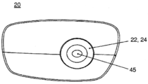
도 4는 본 발명에 따라 도 3에 도시된 충전 조립체(100)의 플러그(10)를 수용할 수 있는 베이스(21)의 표면의 정면도를 나타낸다. 또 다른 실시예에 따르면, 플러그(10)는 플러그(10)의 제2 극 상에 위치하는 제3 전기 커넥터를 포함할 수 있다. 그 후 베이스(21)는, 베이스(21)의 제1 극 상에 위치하여, 접속 표면(11)이 베이스(21) 상에 위치할 때 제3 전기 커넥터(35)와 접속하여 제3 및 제 4 전기 커넥터(35, 45) 간 전기적 접속을 가능하게 할 수 있는 제4 전기 커넥터(45)를 포함할 수 있다. 구체형 캡의 형태를 갖는 플러그(10)와 상보적 형태의 베이스(21)의 경우, 제4 전기 커넥터(45)는 표면 커넥터(24)의 중앙에 위치하는 중앙 블록을 형성한다. 표면 커넥터(24)와 제4 전기 커넥터(45)는 동심인 것이 바람직하다.Figure 4 shows a front view of the surface of the base 21 capable of receiving the
도 5는 본 발명에 따라 충전 조립체(100)의 플러그(10)의 전기 커넥터의 횡단면도를 개략적으로 나타낸다. 이는 스팟 커넥터(50)이다. 스팟 커넥터(50)는 접속 표면(11)과의 제1 접속점(51)을 형성한다. 본 발명에 따르면, 조립체(100)는 제1 전기 커넥터 및 제2 전기 커넥터 중 하나가 제1 접속점(51)을 통과하여 접속 표면(11)에 실질적으로 직각으로 제1 축(52)을 따라 접속 표면(11)에 대해 병진 운동 자유도를 갖도록 구성된다. 이는 각각의 스팟 커넥터에 적용된다. 이 자유도는 각각의 스팟 커넥터의 가벼운 방사 방향 및 독립적 움직임을 가능하게 한다. 존재 검출기는, 각자의 부분에 대해, 견고하게 장착되고 케이블에 의해 지지되는 힘을 견딘다. 케이블의 움직임이 구체의 부분의 표면 상에 분포되며, 들어 올려지고 플러그와 베이스 간 물리적 접속을 끊는 하나 이상의 존재 검출기로 전달된다. 자기 커넥터를 제자리로 고정하는 힘과 연관된 전기 커넥터의 장착의 가요성이, 즉시 반응하는 존재 검출기와 달리, 충전 접속을 끊을 때 딜레이를 도입한다. 이 순서화에 의해 존재 검출기가 플러그가 갑작스럽게 뽑혔음을 충전기에게 알려주고 전기적 접속의 끊김에 앞서 이를 할 수 있다. 그 후 전기 커넥터들 간 전기 아크의 형성을 피하기 위해 전달된 전력이 차단될 수 있다.5 schematically illustrates a cross-sectional view of an electrical connector of a
바람직하게는, 접속 표면(11)이 제1 축(51)에 실질적으로 직각으로 제2 축을 따르는 병진 운동 자유도를 가지며 접속 표면(11)이 베이스(21) 상에 위치될 때 제1 전기 커넥터(22)와 제2 전기 커넥터(12)의 접속을 촉진시키도록 구성된 가요성 구역(32)을 포함한다. 가요성 구역(32)에 의해 플러그(11)의 전기 커넥터가 플러그(11) 및 베이스(21)와의 적절한 접속을 보장하기 위한 특정 자유도를 가능하게 한다. 따라서 가요성 구역(32)의 가요성에 의해 제2 전기 커넥터(12)가 베이스(21)의 표면에 직각으로 축을 따라 배향될 수 있는 것이 바람직하다.Preferably the connecting
전기 커넥터와 자기 커넥터와 연관된 존재 검출기의 교대하는 분포가 표면 커넥터 상의 스팟 커넥터의 위치에 무관하게 세밀한 정렬 시스템 및 작업을 필요로 하지 않는다는 이점을 제공한다. The alternate distribution of the presence detectors associated with the electrical connector and the magnetic connector provides the advantage that a fine alignment system and operation is not required regardless of the position of the spot connector on the surface connector.
하나의 실시예에서, 전원이 양극과 음극을 갖는 DC 전압원이다. 바람직하게는, 제3 전기 커넥터(35)가 전원의 음극에 연결되고 제2 전기 커넥터(12)가 전원의 양극에 연결된다. 가요성 구역(32) 및 제3 전기 커넥터(35)의 중앙 위치설정 덕분에, 플러그(10)가 원치 않게 뽑히는 경우가 발생하는 경우, 제3 커넥터(35)가 베이스로부터 가장 나중에 분리되고, 이로써 전기 아크의 형성이 피해질 수 있다. 예를 들어, 전기 커넥터(35)가 스프링 또는 엘라스토머로 만들어진 부품 또는 특정 탄성을 갖는 그 밖의 다른 임의의 부품 상에 장착될 수 있다. 동일한 원리로, 플러그(10)가 베이스(21)로 가져가 질 때, 제3 전기 커넥터(35)는 우선 연결되는 전기 커넥터이다. In one embodiment, the power source is a DC voltage source having an anode and a cathode. Preferably, the third
추가로, 배터리가 충전되는 동안 전기적 접속을 안정화하도록 제1 접속점(51)을 통과하여 접속 표면(11)에 실질적으로 수직으로 제1 축(52)을 따라 힘을 발생시키도록 충전 조립체가 구성될 수 있다. In addition, the charging assembly is configured to generate a force along the
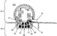
도 6은 본 발명에 따르는 충전 조립체(100)의 플러그(10)의 횡단면도를 개략적으로 나타낸다. 이 횡단면도에 의해 플러그(10)의 접속 표면(11) 상의 존재 검출기(33)의 하나의 가능한 구성을 나타내는 것이 가능하다. 마찬가지로, 자기 커넥터(13)는 전기 커넥터(12)와 교대로 배열되어, 베이스(21)의 전기 커넥터(22)와 전기 커넥터(12)의 우수한 정렬을 지지할 수 있다. Figure 6 schematically illustrates a cross-sectional view of a
도 7은 본 발명에 따르는 충전 조립체(100)의 플러그(10)의 횡단면도를 개략적으로 나타내는데, 여기서 플러그(10)의 접속 표면(11)이 물체(20)의 베이스(21)의 표면과 접촉한다. 자기 커넥터(13, 23)는 플러그(10)가 베이스(21)로 제공되는 동안 우선순위화된 축 없이 임의의 기계적 안내부 및 작업을 제거한다. 어떠한 부품도 다른 곳으로 삽입되지 않기 때문에 어떠한 특정 안내부도 필요하지 않다. 플러그(10)가 베이스(21) 상에 올바르게 위치하기에는 비교적 낮은 정확도의 움직임이 충분하다.Figure 7 schematically shows a cross-sectional view of a
또한, 전기 커넥터의 구체형 배열이 접속 평면으로 배향될 필요성을 제거하고 베이스(21) 상에 놓도록 플러그(10)를 쥘 때 전기 커넥터의 어떠한 특정 배향도 부가하지 않는다. It also does not add any particular orientation of the electrical connector when gripping the
도 8은 본 발명에 따르는 충전 조립체(100)의 물체(20)의 횡단면도를 개략적으로 나타낸다. 이 횡단면도에 의해 베이스(21)의 표면의 중앙에 위치하는 제4 전기 커넥터(45)의 한 가지 가능한 구성을 나타내는 것이 가능하다. 이 구성에서, 베이스(21)의 전기 커넥터는 표면 커넥터(24)이다. 도 6에서와 같이, 자기 커넥터(23)는 전기 커넥터(45, 24)와 교대로 배열되어, 베이스(21)의 전기 커넥터와 전기 커넥터(12)의 바람직한 정렬이 촉진될 수 있다. Figure 8 schematically shows a cross-sectional view of an
도 9는 본 발명에 따르는 충전 조립체(100)를 구현하는 충전 방법의 단계를 도시한다. 상기 방법은 베이스(21) 상으로의 플러그(10)의 접속 표면(11)의 위치 설정 단계(1001)와 제1 및 제2 전기 커넥터(22, 12)의 정렬 단계(1002)를 포함한다. Figure 9 illustrates the steps of a charging method for implementing a charging
상기 방법은 또한 다음의 단계를 포함하는 충전을 활성화하는 단계(1003)를 포함할 수 있다:The method may also include activating a charge (1003) comprising the following steps:
·존재 검출기(33)에 의해 물체 상의 플러그(10)의 존재 여부를 검증하는 단계,Verifying the presence of the
·배터리의 단자에서 전압을 측정하고 측정된 전압을 최소 전압 값 및 최대 전압 값과 비교하는 단계, Measuring the voltage at the terminals of the battery and comparing the measured voltage with a minimum voltage value and a maximum voltage value,
·배터리의 내부 저항을 측정하고 측정된 저항을 최소 저항 값과 최대 저항 값과 비교하는 단계. Measuring the internal resistance of the battery and comparing the measured resistance with the minimum resistance value and the maximum resistance value.
상기 방법은 또한 다음에서 나열된 순서로 수행되는 다음의 단계들을 포함하는 충전 종료 단계(1004)를 포함한다:The method also includes a
·제2 전기 커넥터(12)와 제1 전기 커넥터(22)를 분리하는 단계,Separating the second
·제4 전기 커넥터(45)와 제3 전기 커넥터(35)를 분리하는 단계.Separating the fourth
도 10은 본 발명에 따르는 충전 조립체(100)의 플러그(10)를 이용해 충전되도록 구성된 휴머노이드 로봇을 나타낸다. 도 10의 로봇(200)이 본 발명에 따라 충전 조립체(100)의 플러그(10)를 이용해 충전되도록 구성된 휴머노이드 로봇의 하나의 예시이다. 도 10의 로봇(200)의 하부 부분은 보행을 위해 동작하지 않고, 로봇(200)이 위치하는 표면 상에서 구르는 주춧대(140) 상에서 임의의 방향으로 이동할 수 있다. 이 예시에서, 로봇(200)은 대략 120cm일 수 있는 높이(110), 대략 65cm의 깊이(120), 및 대략 40cm의 폭(130)을 가진다. 특정 구성에서, 로봇은 메시지(오디오, 비디오, 인터넷 페이지)를 자신의 주위로 통신하거나 태블릿의 터치 인터페이스를 통해 사용자 입력을 수신할 수 있는 태블릿(150)을 가진다. 태블릿의 프로세서에 추가로, 로봇은 또한 예를 들어, Intel™의 ATOM™ Z530 보드일 수 있는 자신의 고유 마더보드의 프로세서를 이용한다. 바람직하게는, 본 발명의 하나의 실시예에서, 로봇은 마더보드와 자기 회전 센서(MRE: Magnetic Rotary Encoder)와 사지의 관절과 로봇이 휠로서 사용하는 볼(ball)의 모터를 제어하는 센서를 지원하는 보드 간 데이터 스트림에 특화된 프로세서를 가진다. 모터는 정의된 관절을 위해 요구되는 최대 토크의 진폭에 따라 달라지는 여러 다른 유형의 모터일 수 있다. 예를 들어, e-minebea™의 코어리스(coreless) DC 브러시 모터(가령, SE24P2CTCA) 또는 Maxon™의 브러시리스(brushless) DC 모터(가령, EC45_70W)가 사용될 수 있다. 자기 회전 센서는 12 또는 14비트의 정밀도로 홀 효과(Hall effect)를 이용하는 것이 바람직하다. 10 shows a humanoid robot configured to be charged using a
도 10에 도시된 로봇은 여러 다른 유형의 센서를 더 포함할 수 있다. 특정 센서가 로봇의 위치 및 운동을 제어하는 데 사용된다. 예를 들어 로봇의 몸통에 위치하고 3축 자이로미터 및 3축 가속도계를 포함하는 관성 유닛이 있다. 로봇은 로봇의 전면에 시스템 온 칩(즉, SOC) 유형의 2개의 RGB 컬러 2D 카메라, 가령, 초당 5개의 이미지로 5메가픽셀의 해상도 및 수평으로 대략 57° 및 수직으로 44°의 시야(이른바 FOV)를 갖는 Shenzen V-Vision Technology Ltd™의 카메라(OV5640)를 더 포함할 수 있다. 3D 센서, 가령, 초당 20개의 이미지로 0.3메가픽셀의 해상도를 가지며 2D 카메라와 거의 동일한 시야를 갖는 ASUS XTION™ SOC 센서가 로봇의 눈 뒤에 포함될 수 있다. 상기 로봇은 레이저 라인 발생기, 가령, 머리 높이에 3개 및 베이스에 3개를 구비하여, 주위 물체 및/또는 인간과 관련된 자신의 상대적 위치를 검출할 수 있다. 상기 로봇은 자신의 주위 소리를 검출할 수 있도록 마이크로폰을 더 포함할 수 있다. 하나의 실시예에서, 1kHz에서 300 mV/Pa +/-3dB의 감도 및 300Hz 내지 12kHz의 주파수 범위(1kHz에 대해 -10dB)를 갖는 4개의 마이크로폰이 로봇의 머리에 이식될 수 있다. 로봇은 자신의 베이스의 정면 및 후면에 위치할 수 있는 2개의 소나 센서(sonar sensor)를 더 포함하여 로봇을 주위의 물체 및/또는 사람으로부터 분리시키는 거리를 측정할 수 있다. 로봇은 또한 자신의 머리 및 손 상에 터치 센서를 포함하여, 인간과의 상호대화를 가능하게 할 수 있다. 로봇은 또한 경로 중에 만나게 되는 장애물로부터 스스로를 보호하기 위해 베이스 상에 범퍼(bumper)를 포함할 수 있다. The robot shown in Fig. 10 may further include various other types of sensors. A specific sensor is used to control the position and movement of the robot. For example, there is an inertial unit located in the torso of a robot and including a triaxial gyrometer and a triaxial accelerometer. The robot has two RGB color 2D cameras of the system on chip (i.e., SOC) type on the front of the robot, a resolution of 5 megapixels with five images per second, and a view angle of about 57 degrees horizontally and 44 degrees vertically (OV5640) of Shenzen V-Vision Technology Ltd < / RTI > 3D sensors, such as the ASUS XTION ™ SOC sensor with a resolution of 0.3 megapixels, for example, 20 images per second, with nearly the same field of view as a 2D camera, can be included behind the eyes of the robot. The robots may be equipped with a laser line generator, e.g. three at the head height and three at the base, to detect their relative position with respect to the surrounding object and / or the human being. The robot may further include a microphone for detecting the surround sound of the robot. In one embodiment, four microphones having a sensitivity of 300 mV / Pa +/- 3dB at 1 kHz and a frequency range of 300 Hz to 12 kHz (-10 dB versus 1 kHz) can be implanted in the head of the robot. The robot may further include two sonar sensors that can be positioned at the front and back of its base to measure the distance separating the robot from surrounding objects and / or persons. The robot can also include a touch sensor on its head and hands to enable interaction with humans. The robot may also include a bumper on the base to protect itself from obstacles encountered in the path.
로봇의 감정을 반영하고 주위 인간과 통신하기 위해, 로봇은 다음을 더 포함할 수 있다:In order to reflect the feelings of the robot and communicate with the surrounding human beings, the robot may further include:
- 가령, 로봇의 눈, 귀, 및 어깨에 LED, 즉, 발광 다이오드, For example, LEDs on the eyes, ears, and shoulders of robots, ie light emitting diodes,
- 확성기, 예를 들어 2개의 확성기가 귀에 위치함.- loudspeakers, eg two loudspeakers located in the ear.
로봇은 이더넷 RJ45 또는 WiFi 802.11 연결을 통해 기지국 또는 다른 로봇과 통신할 수 있다. The robot can communicate with the base station or other robots via an Ethernet RJ45 or WiFi 802.11 connection.
로봇은 대략 400Wh의 에너지를 갖는 리튬 철 인산염 배터리 또는 대략 860Wh의 리튬 폴리머 트리믹스(리튬 코발트 망간) 배터리에 의해 전력을 공급받을 수 있다. 상기 로봇은 자신이 갖고 있는 배터리의 유형에 적합한 충전 장치를 액세스할 수 있다. The robot can be powered by a lithium iron phosphate battery with an energy of approximately 400 Wh or a lithium polymer trimmix (lithium cobalt manganese) battery of approximately 860 Wh. The robot can access a charging device suitable for the type of battery it has.
로봇의 위치 및 운동이, 센서로부터의 측정치가 주어질 때, 각각의 사지 및 각각의 사지의 말단에서 형성된 실행기(effector)로 형성된 체인에 의해 활성화되는 알고리즘을 이용함으로써 모터에 의해 제어된다. The position and motion of the robot is controlled by the motor by using an algorithm that is activated by a chain formed by an effector formed at the extremities of each limb and each extremity when given a measurement from the sensor.
본 발명에 따르는 충전 조립체(100)을 이용해 충전되도록 로봇(200)은 플러그(10)를 수용할 수 있는 베이스(21)를 포함한다. 이는 충전 조립체(100)가 인가될 수 있는 물체의 하나의 예시로서 역할한다. The
Claims (12)
배터리를 포함하는 물체(20)와,
상기 배터리를 충전하기 위한 플러그(10)
를 포함하고, 상기 플러그(10)는 전원에 연결될 수 있으며,
물체(20)는,
플러그(10)를 수용할 수 있는 베이스(21)를 포함하며, 상기 베이스는
제1 전기 커넥터(22)와,
플러그(10)를 베이스(21)에 대해 위치설정할 수 있는 제1 자기 커넥터(23)
를 포함하며, 상기 플러그(10)는,
베이스(21)의 표면에 상보적인 형태의 접속 표면(11)과,
접속 표면(11)이 베이스(21)의 표면 상에 위치될 때 제1 전기 커넥터(22)와 제2 전기 커넥터(12) 간 전기적 접속을 가능하게 하도록 제1 전기 커넥터(22)와 접속하도록 배열된 제2 전기 커넥터(12)와,
상기 접속 표면(11)에 근접하게 위치설정되며, 제1 자기 커넥터(23)를 끌어 당겨, 배터리가 충전되는 동안 제1 전기 커넥터와 제2 전기 커넥터의 정렬 및 전기적 접속이 안정화되게 하는 제2 자기 커넥터(13)를 포함하고,
제1 전기 커넥터(22)와 제2 전기 커넥터(12) 중 하나는 표면 커넥터(24)이고 제1 전기 커넥터와 제2 전기 커넥터 중 다른 하나는, 베이스(21) 상에서의 접속 표면(11)의 복수의 개별적인 배향에 대해, 상기 표면 커넥터(24)에 대해 배치되도록 구성된 스팟 커넥터(spot connector)(14)이며,
상기 플러그(10)는 전기 케이블(15)에 의해 전원에 연결될 수 있으며, 상기 플러그(10)는,
제2 전기 커넥터(12)와 제2 자기 커넥터(13)가 고정된 몸체(16),
상기 몸체(16)에 대해 회전 이동하는 이동 부분(17) - 상기 케이블(15)은 상기 이동 부분(17)의 회전을 가능하게 하는 가요성 와이어에 의해 상기 이동 부분(17)에 고정되며 커넥터(12)에 전기적으로 링크됨 - 을 포함하는, 충전 조립체.A charging assembly (100), the charging assembly
An object 20 including a battery,
A plug 10 for charging the battery,
, Said plug (10) being connectable to a power source,
The object (20)
And a base (21) capable of receiving the plug (10), said base
A first electrical connector 22,
A first magnetic connector (23) capable of positioning the plug (10) relative to the base (21)
Wherein the plug (10)
A connection surface 11 of a complementary type to the surface of the base 21,
Is arranged to connect with the first electrical connector 22 to enable electrical connection between the first electrical connector 22 and the second electrical connector 12 when the connecting surface 11 is located on the surface of the base 21 A second electrical connector 12,
A second magnetic connector positioned proximate to the connection surface and pulling the first magnetic connector to allow alignment and electrical connection of the first electrical connector and the second electrical connector to be stabilized while the battery is being charged, And a connector (13)
One of the first electrical connector 22 and the second electrical connector 12 is a surface connector 24 and the other of the first electrical connector and the second electrical connector is connected to the connection surface 11 A spot connector (14) configured to be positioned relative to the surface connector (24) for a plurality of individual orientations,
The plug 10 may be connected to a power source by means of an electrical cable 15,
A body 16 to which the second electrical connector 12 and the second magnetic connector 13 are fixed,
A moving part (17) rotating with respect to the body (16), the cable (15) being fixed to the moving part (17) by means of a flexible wire enabling rotation of the moving part (17) 12). ≪ / RTI >
접속 표면(11)을 베이스(21)의 표면 상에 위치설정하는 단계(1001),
제1 전기 커넥터(22)와 제2 전기 커넥터(12)를 정렬하는 단계(1002)를 포함하는, 충전 방법.10. A charging method for implementing a charging assembly (100) according to any one of claims 1 to 9,
Positioning (1001) the connecting surface (11) on the surface of the base (21)
And aligning (1002) the first electrical connector (22) and the second electrical connector (12).
존재 검출기(33)에 의해 물체(20) 상에서의 플러그(10)의 존재를 검증하는 단계,
배터리의 단자에서의 전압을 측정하고 측정된 전압을 최소 전압 값과 최대 전압 값에 비교하는 단계,
배터리의 내부 저항을 측정하고 측정된 저항을 최소 저항 값 및 최대 저항 값에 비교하는 단계
를 포함하는, 충전 방법. 11. The method of claim 10, wherein when implementing the filler assembly (100) according to any one of claims 3 to 10, the method further comprises a filler activation step (1003)
Verifying the presence of the plug 10 on the object 20 by the presence detector 33,
Measuring a voltage at a terminal of the battery and comparing the measured voltage to a minimum voltage value and a maximum voltage value,
Measuring the internal resistance of the battery and comparing the measured resistance to a minimum resistance value and a maximum resistance value
. ≪ / RTI >
제2 전기 커넥터와 제1 전기 커넥터를 분리하는 단계,
제4 전기 커넥터와 제3 전기 커넥터를 분리하는 단계
를 포함하는, 충전 방법.
12. The method of claim 10 or claim 11, wherein when implementing the charging assembly (100) according to any one of claims 7 to 9, the method comprises a charging termination step (1004) Are performed in order
Separating the second electrical connector and the first electrical connector,
Separating the fourth electrical connector and the third electrical connector
. ≪ / RTI >
Applications Claiming Priority (3)
| Application Number | Priority Date | Filing Date | Title |
|---|---|---|---|
| FR1651785 | 2016-03-02 | ||
| FR1651785A FR3048560B1 (en) | 2016-03-02 | 2016-03-02 | BATTERY RECHARGING ASSEMBLY AND RECHARGING METHOD USING SUCH ASSEMBLY |
| PCT/EP2017/054519 WO2017148867A1 (en) | 2016-03-02 | 2017-02-27 | Assembly for charging a battery and charging method implementing such an asssembly |
Publications (1)
| Publication Number | Publication Date |
|---|---|
| KR20180098683A true KR20180098683A (en) | 2018-09-04 |
Family
ID=56101604
Family Applications (1)
| Application Number | Title | Priority Date | Filing Date |
|---|---|---|---|
| KR1020187024266A Abandoned KR20180098683A (en) | 2016-03-02 | 2017-02-27 | Battery charging assembly and charging method for implementing such an assembly |
Country Status (13)
| Country | Link |
|---|---|
| US (1) | US20210184396A1 (en) |
| EP (1) | EP3424111A1 (en) |
| JP (1) | JP2019509595A (en) |
| KR (1) | KR20180098683A (en) |
| CN (1) | CN108701938B (en) |
| AU (1) | AU2017226859B2 (en) |
| BR (1) | BR112018017158A2 (en) |
| CA (1) | CA3015586C (en) |
| FR (1) | FR3048560B1 (en) |
| MX (1) | MX2018009754A (en) |
| RU (1) | RU2692767C1 (en) |
| SG (1) | SG11201806732SA (en) |
| WO (1) | WO2017148867A1 (en) |
Cited By (1)
| Publication number | Priority date | Publication date | Assignee | Title |
|---|---|---|---|---|
| WO2026023828A1 (en) * | 2024-07-26 | 2026-01-29 | 주식회사 센서뷰 | Connector system configured to be coupled or separated on basis of magnetic force |
Families Citing this family (4)
| Publication number | Priority date | Publication date | Assignee | Title |
|---|---|---|---|---|
| JP7013398B2 (en) * | 2019-01-15 | 2022-01-31 | 本田技研工業株式会社 | Connector device and connector connection judgment device |
| CN111817394B (en) * | 2020-07-17 | 2022-03-01 | 上海布鲁可积木科技有限公司 | Pairing structure between pairing parts |
| WO2024090164A1 (en) * | 2022-10-24 | 2024-05-02 | ソニーグループ株式会社 | Magnet device, magnet connection structure, and magnet connection method |
| FR3160067A1 (en) | 2024-03-06 | 2025-09-12 | Stellantis Auto Sas | ELECTRICAL PLUG FORMING A SOLID ROUND HANDLE |
Family Cites Families (21)
| Publication number | Priority date | Publication date | Assignee | Title |
|---|---|---|---|---|
| US1984181A (en) * | 1933-03-24 | 1934-12-11 | Anaconda Wire & Cable Co | Attachment plug |
| JPH02140775U (en) * | 1989-04-28 | 1990-11-26 | ||
| IL159032A0 (en) * | 2003-11-24 | 2004-05-12 | Safety Quick Light Ltd | Swivellable electric socket-plug combination |
| JP2006210269A (en) * | 2005-01-31 | 2006-08-10 | Sanyo Electric Co Ltd | Connector |
| US7477039B2 (en) * | 2005-05-19 | 2009-01-13 | International Business Machines Corporation | Method and apparatus for charging a portable electrical device |
| JP2009106096A (en) * | 2007-10-24 | 2009-05-14 | Panasonic Corp | Autonomous traveling device and program |
| JP4943296B2 (en) * | 2007-10-30 | 2012-05-30 | ソニー株式会社 | Battery pack, secondary battery charging method, and charging device |
| DE202008013600U1 (en) * | 2008-08-12 | 2008-12-24 | Magcode Ag | Device for producing a compound |
| EP2533374A1 (en) * | 2011-06-06 | 2012-12-12 | novero GmbH | Connector assembly with a magnetic fixation |
| CN202134730U (en) * | 2011-06-10 | 2012-02-01 | 陈宏宇 | power supply unit |
| TWI429147B (en) * | 2011-06-21 | 2014-03-01 | Wistron Corp | Plug assembly adapted to an adapter and a computer device |
| JP5610086B2 (en) * | 2011-10-25 | 2014-10-22 | 住友電装株式会社 | Vehicle charging device |
| US9153983B2 (en) * | 2011-12-29 | 2015-10-06 | Sony Corporation | Charging device |
| US20140120746A1 (en) * | 2012-10-24 | 2014-05-01 | Rostislav Persion | Electrical and fiber optic connector with magnetic electrical contacts |
| CN103972688B (en) * | 2013-01-31 | 2016-07-06 | 纬创资通股份有限公司 | swivel plug |
| KR101265730B1 (en) * | 2013-02-20 | 2013-05-21 | (주)에스피에스 | Magnetic connector module having a circuit for restricting power supply |
| CN203312601U (en) * | 2013-04-12 | 2013-11-27 | 沈单枫 | Plug with rotary function |
| CN203660227U (en) * | 2014-01-04 | 2014-06-18 | 台州鑫来电缆有限公司 | Rotary plug |
| CN204179359U (en) * | 2014-11-18 | 2015-02-25 | 厦门理工学院 | A kind of Novel socket assembly |
| CN104485546B (en) * | 2014-11-28 | 2016-08-17 | 上海理工大学 | Plug-assembly |
| CN104466509A (en) * | 2014-12-24 | 2015-03-25 | 常熟市斯佳登电器有限公司 | Split type power plug |
-
2016
- 2016-03-02 FR FR1651785A patent/FR3048560B1/en not_active Expired - Fee Related
-
2017
- 2017-02-27 JP JP2018545866A patent/JP2019509595A/en not_active Ceased
- 2017-02-27 KR KR1020187024266A patent/KR20180098683A/en not_active Abandoned
- 2017-02-27 MX MX2018009754A patent/MX2018009754A/en unknown
- 2017-02-27 EP EP17707555.3A patent/EP3424111A1/en not_active Withdrawn
- 2017-02-27 AU AU2017226859A patent/AU2017226859B2/en not_active Ceased
- 2017-02-27 RU RU2018134338A patent/RU2692767C1/en not_active IP Right Cessation
- 2017-02-27 SG SG11201806732SA patent/SG11201806732SA/en unknown
- 2017-02-27 US US16/079,506 patent/US20210184396A1/en not_active Abandoned
- 2017-02-27 CN CN201780013799.XA patent/CN108701938B/en not_active Expired - Fee Related
- 2017-02-27 CA CA3015586A patent/CA3015586C/en not_active Expired - Fee Related
- 2017-02-27 WO PCT/EP2017/054519 patent/WO2017148867A1/en not_active Ceased
- 2017-02-27 BR BR112018017158-1A patent/BR112018017158A2/en not_active IP Right Cessation
Cited By (1)
| Publication number | Priority date | Publication date | Assignee | Title |
|---|---|---|---|---|
| WO2026023828A1 (en) * | 2024-07-26 | 2026-01-29 | 주식회사 센서뷰 | Connector system configured to be coupled or separated on basis of magnetic force |
Also Published As
| Publication number | Publication date |
|---|---|
| CA3015586A1 (en) | 2017-09-08 |
| CA3015586C (en) | 2020-08-04 |
| WO2017148867A1 (en) | 2017-09-08 |
| FR3048560B1 (en) | 2019-07-05 |
| CN108701938B (en) | 2020-06-19 |
| AU2017226859B2 (en) | 2019-05-09 |
| BR112018017158A2 (en) | 2018-12-26 |
| US20210184396A1 (en) | 2021-06-17 |
| RU2692767C1 (en) | 2019-06-27 |
| SG11201806732SA (en) | 2018-09-27 |
| AU2017226859A1 (en) | 2018-09-13 |
| JP2019509595A (en) | 2019-04-04 |
| FR3048560A1 (en) | 2017-09-08 |
| MX2018009754A (en) | 2018-12-19 |
| EP3424111A1 (en) | 2019-01-09 |
| CN108701938A (en) | 2018-10-23 |
Similar Documents
| Publication | Publication Date | Title |
|---|---|---|
| KR20180098683A (en) | Battery charging assembly and charging method for implementing such an assembly | |
| DK3152080T3 (en) | CHARGING BASE FOR A BATTERY AND PROCEDURE FOR CHARGING USING SUCH BASE | |
| EP3840398B1 (en) | A wireless hearing device and a charging base | |
| US10056791B2 (en) | Self-optimizing power transfer | |
| US9673647B2 (en) | Charging apparatus for mobile device | |
| US20190157890A1 (en) | Device charging system | |
| EP2793359A1 (en) | Wireless charger capable of automatic position adjustment and charging method using same | |
| US10177490B2 (en) | Magnetic connecting apparatus | |
| US10805547B2 (en) | Imaging device having an elongated bendable section carries an imaging section to capture an image in a predetermined direction | |
| CN105962879A (en) | Pose control system and control method of capsule endoscope and capsule endoscope | |
| FR3048386B1 (en) | METHOD FOR RECHARGING A BATTERY OF A MOBILE VEHICLE BY A RECHARGING PLUG | |
| CN109547889B (en) | Magnetic connectors and bone conduction speaker devices | |
| US20230098043A1 (en) | Connection systems | |
| CN214412345U (en) | Intelligent cradle head | |
| WO2018146088A1 (en) | A wireless binaural hearing device with two charging connectors and a system comprising such a hearing device | |
| CN112531917A (en) | Wireless charging receiving device and electronic equipment | |
| CN109561366B (en) | Magnetic connector and bone conduction speaker | |
| PL70288Y1 (en) | Assembly unit |
Legal Events
| Date | Code | Title | Description |
|---|---|---|---|
| A201 | Request for examination | ||
| PA0105 | International application |
Patent event date: 20180823 Patent event code: PA01051R01D Comment text: International Patent Application |
|
| PA0201 | Request for examination | ||
| PG1501 | Laying open of application | ||
| E902 | Notification of reason for refusal | ||
| PE0902 | Notice of grounds for rejection |
Comment text: Notification of reason for refusal Patent event date: 20191217 Patent event code: PE09021S01D |
|
| E701 | Decision to grant or registration of patent right | ||
| PE0701 | Decision of registration |
Patent event code: PE07011S01D Comment text: Decision to Grant Registration Patent event date: 20200625 |
|
| PC1904 | Unpaid initial registration fee |