KR20180098667A - Method and apparatus for transmitting and receiving wireless signals in a wireless communication system - Google Patents
Method and apparatus for transmitting and receiving wireless signals in a wireless communication system Download PDFInfo
- Publication number
- KR20180098667A KR20180098667A KR1020187022186A KR20187022186A KR20180098667A KR 20180098667 A KR20180098667 A KR 20180098667A KR 1020187022186 A KR1020187022186 A KR 1020187022186A KR 20187022186 A KR20187022186 A KR 20187022186A KR 20180098667 A KR20180098667 A KR 20180098667A
- Authority
- KR
- South Korea
- Prior art keywords
- information
- dci
- subframes
- nsf
- transmission
- Prior art date
- Legal status (The legal status is an assumption and is not a legal conclusion. Google has not performed a legal analysis and makes no representation as to the accuracy of the status listed.)
- Granted
Links
Images


Classifications
-
- H—ELECTRICITY
- H04—ELECTRIC COMMUNICATION TECHNIQUE
- H04W—WIRELESS COMMUNICATION NETWORKS
- H04W72/00—Local resource management
- H04W72/12—Wireless traffic scheduling
- H04W72/1263—Mapping of traffic onto schedule, e.g. scheduled allocation or multiplexing of flows
- H04W72/1268—Mapping of traffic onto schedule, e.g. scheduled allocation or multiplexing of flows of uplink data flows
-
- H—ELECTRICITY
- H04—ELECTRIC COMMUNICATION TECHNIQUE
- H04W—WIRELESS COMMUNICATION NETWORKS
- H04W72/00—Local resource management
- H04W72/04—Wireless resource allocation
- H04W72/044—Wireless resource allocation based on the type of the allocated resource
- H04W72/0446—Resources in time domain, e.g. slots or frames
-
- H—ELECTRICITY
- H04—ELECTRIC COMMUNICATION TECHNIQUE
- H04L—TRANSMISSION OF DIGITAL INFORMATION, e.g. TELEGRAPHIC COMMUNICATION
- H04L5/00—Arrangements affording multiple use of the transmission path
- H04L5/003—Arrangements for allocating sub-channels of the transmission path
- H04L5/0053—Allocation of signalling, i.e. of overhead other than pilot signals
-
- H—ELECTRICITY
- H04—ELECTRIC COMMUNICATION TECHNIQUE
- H04W—WIRELESS COMMUNICATION NETWORKS
- H04W72/00—Local resource management
- H04W72/12—Wireless traffic scheduling
-
- H04W72/1289—
-
- H—ELECTRICITY
- H04—ELECTRIC COMMUNICATION TECHNIQUE
- H04W—WIRELESS COMMUNICATION NETWORKS
- H04W72/00—Local resource management
- H04W72/20—Control channels or signalling for resource management
- H04W72/21—Control channels or signalling for resource management in the uplink direction of a wireless link, i.e. towards the network
-
- H—ELECTRICITY
- H04—ELECTRIC COMMUNICATION TECHNIQUE
- H04W—WIRELESS COMMUNICATION NETWORKS
- H04W72/00—Local resource management
- H04W72/20—Control channels or signalling for resource management
- H04W72/23—Control channels or signalling for resource management in the downlink direction of a wireless link, i.e. towards a terminal
- H04W72/232—Control channels or signalling for resource management in the downlink direction of a wireless link, i.e. towards a terminal the control data signalling from the physical layer, e.g. DCI signalling
Landscapes
- Engineering & Computer Science (AREA)
- Signal Processing (AREA)
- Computer Networks & Wireless Communication (AREA)
- Mobile Radio Communication Systems (AREA)
Abstract
본 발명은 무선 통신 시스템에 관한 것으로서, 구체적으로 복수 서브프레임에 대한 UL 스케줄링 정보를 포함하는 DCI를 수신하되, 상기 DCI는 SRS 요청 정보를 더 포함하는 단계; 및 상기 SRS 요청 정보의 지시에 따라, 상기 복수 서브프레임 내의 기-지정된 서브프레임을 통해 1회만 SRS를 전송하는 단계를 포함하고, 상기 기-지정된 서브프레임은 상기 복수 서브프레임 내에서 UL 전송이 스케줄링된 첫 번째 서브프레임 또는 UL 전송이 스케줄링된 마지막 서브프레임을 포함하는 방법 및 이를 위한 장치에 관한 것이다.The present invention relates to a wireless communication system, and more particularly, to a method and apparatus for receiving a DCI including UL scheduling information for a plurality of subframes, the DCI further including SRS request information. And transmitting SRS only once over a pre-designated subframe in the plurality of subframes according to an indication of the SRS request information, wherein the pre-designated subframe is configured such that UL transmission within the plurality of subframes is scheduled To a first sub-frame or a UL sub-frame that is scheduled for UL transmission, and an apparatus therefor.
Description
본 발명은 무선 통신 시스템에 관한 것으로, 보다 상세하게는 무선 신호 송수신 방법 및 장치에 관한 것이다. 무선 통신 시스템은 CA(Carrier Aggregation)-기반 무선 통신 시스템을 포함한다.BACKGROUND OF THE
무선 통신 시스템이 음성이나 데이터 등과 같은 다양한 종류의 통신 서비스를 제공하기 위해 광범위하게 전개되고 있다. 일반적으로 무선통신 시스템은 가용한 시스템 자원(대역폭, 전송 파워 등)을 공유하여 다중 사용자와의 통신을 지원할 수 있는 다중 접속(multiple access) 시스템이다. 다중 접속 시스템의 예들로는 CDMA(code division multiple access) 시스템, FDMA(frequency division multiple access) 시스템, TDMA(time division multiple access) 시스템, OFDMA(orthogonal frequency division multiple access) 시스템, SC-FDMA(single carrier frequency division multiple access) 시스템 등이 있다.Background of the Invention [0002] Wireless communication systems are widely deployed to provide various types of communication services such as voice and data. Generally, a wireless communication system is a multiple access system capable of supporting communication with multiple users by sharing available system resources (bandwidth, transmission power, etc.). Examples of multiple access systems include a code division multiple access (CDMA) system, a frequency division multiple access (FDMA) system, a time division multiple access (TDMA) system, an orthogonal frequency division multiple access (OFDMA) system, a single carrier frequency division multiple access) systems.
본 발명의 목적은 무선 신호 송수신 과정을 효율적으로 수행하는 방법 및 이를 위한 장치를 제공하는데 있다.SUMMARY OF THE INVENTION It is an object of the present invention to provide a method and apparatus for efficiently performing a wireless signal transmission and reception process.
본 발명에서 이루고자 하는 기술적 과제들은 상기 기술적 과제로 제한되지 않으며, 언급하지 않은 또 다른 기술적 과제들은 아래의 기재로부터 본 발명이 속하는 기술분야에서 통상의 지식을 가진 자에게 명확하게 이해될 수 있을 것이다.The technical problems to be solved by the present invention are not limited to the technical problems and other technical problems which are not mentioned can be understood by those skilled in the art from the following description.
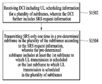
본 발명의 일 양상으로, 무선 통신 시스템에서 단말이 통신을 수행하는 방법에 있어서, 복수 서브프레임에 대한 UL 스케줄링 정보를 포함하는 DCI(Downlink Control Information)를 수신하되, 상기 DCI는 SRS(Sounding Reference Signal) 요청 정보를 더 포함하는 단계; 및 상기 SRS 요청 정보의 지시에 따라, 상기 복수 서브프레임 내의 기-지정된 서브프레임을 통해 1회만 SRS를 전송하는 단계를 포함하고, 상기 기-지정된 서브프레임은 상기 복수 서브프레임 내에서 UL 전송이 스케줄링된 첫 번째 서브프레임 또는 UL 전송이 스케줄링된 마지막 서브프레임을 포함하는 방법이 제공된다.According to an aspect of the present invention, there is provided a method for performing communication in a wireless communication system, the method comprising: receiving DCI (Downlink Control Information) including UL scheduling information for a plurality of subframes, ) Request information; And transmitting SRS only once over a pre-designated subframe in the plurality of subframes according to an indication of the SRS request information, wherein the pre-designated subframe is configured such that UL transmission within the plurality of subframes is scheduled A first sub-frame that has been scheduled or an UL sub-frame that is scheduled for UL transmission is provided.
본 발명의 다른 양상으로, 무선 통신 시스템에 사용되는 단말에 있어서, RF(Radio Frequency) 모듈; 및 프로세서를 포함하고, 상기 프로세서는, 복수 서브프레임에 대한 UL 스케줄링 정보를 포함하는 DCI(Downlink Control Information)를 수신하되, 상기 DCI는 SRS(Sounding Reference Signal) 요청 정보를 더 포함하며, 상기 SRS 요청 정보의 지시에 따라, 상기 복수 서브프레임 내의 기-지정된 서브프레임을 통해 1회만 SRS를 전송하도록 구성되고, 상기 기-지정된 서브프레임은 상기 복수 서브프레임 내에서 UL 전송이 스케줄링된 첫 번째 서브프레임 또는 UL 전송이 스케줄링된 마지막 서브프레임을 포함하는 단말이 제공된다.According to another aspect of the present invention, there is provided a terminal used in a wireless communication system, the terminal comprising: a Radio Frequency (RF) module; And a processor, the processor receiving downlink control information (DCI) including UL scheduling information for a plurality of subframes, the DCI further including SRS (Sounding Reference Signal) request information, wherein the SRS request Wherein the first sub-frame is configured to transmit SRS only once over a pre-specified sub-frame in the plurality of sub-frames, in accordance with an indication of information, the first-sub-frame in which the UL transmission is scheduled within the plurality of sub- A terminal is provided in which the UL transmission includes the last scheduled subframe.
바람직하게, 상기 UL 스케줄링 정보에 기반하여, 상기 복수 서브프레임에서 복수의 UL 전송을 더 수행할 수 있다.Preferably, based on the UL scheduling information, a plurality of UL transmissions may be further performed in the plurality of subframes.
바람직하게, 상기 UL 전송은 PUSCH(Physical Uplink Shared Channel)을 포함할 수 있다.Preferably, the UL transmission may include a Physical Uplink Shared Channel (PUSCH).
바람직하게, 상기 DCI는 비면허 밴드에서 동작하는 UCell(unlicensed cell) 상의 복수 서브프레임에 대한 UL 스케줄링 정보를 포함하고, 상기 SRS는 상기 UCell 상에서 전송될 수 있다.Preferably, the DCI includes UL scheduling information for a plurality of subframes on an unlicensed cell (UCell) operating in a license-exempt band, and the SRS can be transmitted on the UCell.
바람직하게, 상기 DCI는 상기 UCell 또는 면허 밴드에서 동작하는 LCell(licensed cell) 상에서 수신될 수 있다.Preferably, the DCI may be received on a licensed cell (LCell) operating in the UCell or license band.
바람직하게, 상기 DCI는 상기 복수 서브프레임에서 UL 전송이 스케줄링된 서브프레임의 개수를 지시하는 정보를 더 포함할 수 있다.Advantageously, the DCI may further comprise information indicating the number of subframes for which UL transmission is scheduled in the plurality of subframes.
바람직하게, 상기 무선 통신 시스템은 LTE(Long Term Evolution) LAA(License Assisted Access)-기반 무선 통신 시스템을 포함할 수 있다.Advantageously, the wireless communication system may comprise a Long Term Evolution (LTE) License Assisted Access (LAA) -based wireless communication system.
본 발명의 또 다른 양상으로, 무선 통신 시스템에서 단말이 통신을 수행하는 방법에 있어서, 복수 서브프레임에 대한 UL 스케줄링 정보를 포함하는 DCI(Downlink Control Information)를 수신하되, 상기 DCI는 UL 전송이 스케줄링된 서브프레임의 개수 Nsf를 지시하는 정보를 더 포함하고, 상기 UL 스케줄링 정보에 기반하여, 상기 복수 서브프레임에서 Nsf개의 UL 전송을 수행하는 단계를 포함하고, 상기 DCI의 사이즈는 UL 전송이 스케줄링 될 수 있는 서브프레임의 최대 개수 Nsf_max에 맞춰 정의되며, Nsf가 Nsf_max보다 작은 방법이 제공된다.According to another aspect of the present invention, there is provided a method for performing communication in a wireless communication system, the method comprising: receiving DCI (Downlink Control Information) including UL scheduling information for a plurality of subframes, And performing Nsf UL transmissions in the plurality of subframes based on the UL scheduling information, wherein the size of the DCI is determined such that UL transmission is scheduled Lt; RTI ID = 0.0 > Nsf_max, < / RTI > and Nsf is less than Nsf_max.
본 발명의 또 다른 양상으로, 무선 통신 시스템에 사용되는 단말에 있어서, RF(Radio Frequency) 모듈; 및 프로세서를 포함하고, 상기 프로세서는, 복수 서브프레임에 대한 UL 스케줄링 정보를 포함하는 DCI(Downlink Control Information)를 수신하되, 상기 DCI는 UL 전송이 스케줄링된 서브프레임의 개수 Nsf를 지시하며, 상기 UL 스케줄링 정보에 기반하여, 상기 복수 서브프레임에서 Nsf개의 UL 전송을 수행하도록 구성되고, 상기 DCI의 사이즈는 UL 전송이 스케줄링 될 수 있는 서브프레임의 최대 개수 Nsf_max에 맞춰 정의되며, Nsf가 Nsf_max보다 작은 단말이 제공될 수 있다.According to still another aspect of the present invention, there is provided a terminal used in a wireless communication system, the terminal comprising: a Radio Frequency (RF) module; And a processor, the processor receiving DCI (Downlink Control Information) including UL scheduling information for a plurality of subframes, wherein the DCI indicates the number of scheduled subframes, Nsf, Wherein the size of the DCI is defined according to a maximum number Nsf_max of subframes in which UL transmission can be scheduled, and the size of the DCI is defined according to the number of subframes whose Nsf is smaller than Nsf_max Can be provided.
바람직하게, 상기 DCI의 사이즈는 Nsf_max개의 NDI(New Data Indication) 비트를 기준으로 정의되며, 상기 DCI에서는 UL 전송이 스케줄링된 서브프레임에 대응하는 Nsf개의 NDI 비트만 사용될 수 있다.Preferably, the size of the DCI is defined based on Nsf_max NDI (New Data Indication) bits. In the DCI, only Nsf NDI bits corresponding to a scheduled subframe for UL transmission can be used.
바람직하게, 상기 DCI는 Nsf개의 서브프레임에 공통으로 적용되는 제1 정보, Nsf개의 서브프레임 중 하나의 서브프레임에만 적용되는 제2 정보, Nsf개의 서브프레임에 속하는 각각의 서브프레임에 개별적으로 적용되는 제3 정보를 포함하고,Preferably, the DCI includes first information commonly applied to Nsf subframes, second information applied only to one subframe among Nsf subframes, and second information applied to each subframe belonging to Nsf subframes Third information,
- 상기 제1 정보는 RA(Resource Allocation) 정보, MCS(Modulation and Coding Scheme) 정보, DMRS CS(Demodulation Reference Signal Cyclic Shift) 정보, 및 TPC(Transmit Power Control) 정보를 포함하며,The first information includes Resource Allocation (RA) information, MCS (Modulation and Coding Scheme) information, DMRS CS (Demodulation Reference Signal Cyclic Shift) information, and TPC (Transmit Power Control)
- 상기 제2 정보는 CSI(Channel State Information) 요청 정보, 및 SRS(Sounding Reference Signal) 정보를 포함하고,The second information includes CSI (Channel State Information) request information and SRS (Sounding Reference Signal) information,
- 상기 제3 정보는 NDI(New Data Indicator) 정보, RV(Redundancy Version) 정보, 및 HARQ(Hybrid ARQ) 프로세스 번호 정보를 포함할 수 있다.The third information may include NDI (New Data Indicator) information, RV (Redundancy Version) information, and HARQ (Hybrid ARQ) process number information.
본 발명에 의하면, 무선 통신 시스템에서 무선 신호 송수신을 효율적으로 수행할 수 있다.According to the present invention, wireless signal transmission and reception can be efficiently performed in a wireless communication system.
본 발명에서 얻은 수 있는 효과는 이상에서 언급한 효과들로 제한되지 않으며, 언급하지 않은 또 다른 효과들은 아래의 기재로부터 본 발명이 속하는 기술분야에서 통상의 지식을 가진 자에게 명확하게 이해될 수 있을 것이다.The effects obtained by the present invention are not limited to the above-mentioned effects, and other effects not mentioned can be clearly understood by those skilled in the art from the following description will be.
본 발명에 관한 이해를 돕기 위해 상세한 설명의 일부로 포함되는, 첨부 도면은 본 발명에 대한 실시예를 제공하고, 상세한 설명과 함께 본 발명의 기술적 사상을 설명한다.
도 1은 무선 통신 시스템의 일례인 3GPP LTE(-A) 시스템에 이용되는 물리 채널들 및 이들을 이용한 일반적인 신호 전송 방법을 예시한다.
도 2는 무선 프레임(radio frame)의 구조를 예시한다.
도 3은 하향링크 슬롯의 자원 그리드(resource grid)를 예시한다.
도 4는 하향링크 서브프레임의 구조를 나타낸다.
도 5는 EPDCCH(enhanced Physical Downlink Control Channel)를 예시한다.
도 6은 LTE(-A)에서 사용되는 상향링크 서브프레임의 구조를 예시한다.
도 7은 상향링크-하향링크 프레임 타이밍을 예시한다.
도 8은 UL HARQ(Uplink Hybrid Automatic Repeat reQuest) 동작을 예시한다.
도 9는 캐리어 병합(Carrier Aggregation, CA) 통신 시스템을 예시한다.
도 10은 크로스-캐리어 스케줄링(cross-carrier scheduling)을 예시한다.
도 11은 면허 밴드(licensed band)와 비면허 밴드(unlicensed band)의 캐리어 병합을 예시한다.
도 12~13은 비면허 밴드 내에서 자원을 점유하는 방법을 예시한다.
도 14는 본 발명에 따른 UL 전송 과정을 예시한다.
도 15는 본 발명에 따른 SRS 전송 과정을 예시한다.
도 16은 본 발명에 적용될 수 있는 기지국 및 단말을 예시한다.BRIEF DESCRIPTION OF THE DRAWINGS The accompanying drawings, which are included to provide a further understanding of the invention and are incorporated in and constitute a part of the specification, illustrate embodiments of the invention and, together with the description, serve to explain the principles of the invention.
FIG. 1 illustrates physical channels used in a 3GPP LTE (-A) system, which is an example of a wireless communication system, and a general signal transmission method using them.
Fig. 2 illustrates the structure of a radio frame.
3 illustrates a resource grid of a downlink slot.
4 shows a structure of a downlink sub-frame.
5 illustrates an enhanced Physical Downlink Control Channel (EPDCCH).
6 illustrates a structure of an uplink subframe used in LTE (-A).
FIG. 7 illustrates uplink-downlink frame timing.
FIG. 8 illustrates an uplink Hybrid Automatic Repeat reQuest (UL HARQ) operation.
Figure 9 illustrates a Carrier Aggregation (CA) communication system.
Figure 10 illustrates cross-carrier scheduling.
Figure 11 illustrates the merging of licensed bands and unlicensed bands.
Figures 12-13 illustrate how to occupy resources within a license-exempt band.
14 illustrates a UL transmission process according to the present invention.
15 illustrates an SRS transmission process according to the present invention.
16 illustrates a base station and a terminal that can be applied to the present invention.
이하의 기술은 CDMA(code division multiple access), FDMA(frequency division multiple access), TDMA(time division multiple access), OFDMA(orthogonal frequency division multiple access), SC-FDMA(single carrier frequency division multiple access) 등과 같은 다양한 무선 접속 시스템에 사용될 수 있다. CDMA는 UTRA(Universal Terrestrial Radio Access)나 CDMA2000과 같은 무선 기술(radio technology)로 구현될 수 있다. TDMA는 GSM(Global System for Mobile communications)/GPRS(General Packet Radio Service)/EDGE(Enhanced Data Rates for GSM Evolution)와 같은 무선 기술로 구현될 수 있다. OFDMA는 IEEE 802.11 (Wi-Fi), IEEE 802.16 (WiMAX), IEEE 802-20, E-UTRA(Evolved UTRA) 등과 같은 무선 기술로 구현될 수 있다. UTRA는 UMTS(Universal Mobile Telecommunications System)의 일부이다. 3GPP(3rd Generation Partnership Project) LTE(long term evolution)은 E-UTRA를 사용하는 E-UMTS(Evolved UMTS)의 일부이고 LTE-A(Advanced)는 3GPP LTE의 진화된 버전이다. 설명을 명확하게 하기 위해, 3GPP LTE/LTE-A를 위주로 기술하지만 본 발명의 기술적 사상이 이에 제한되는 것은 아니다.The following description is to be understood as illustrative and non-limiting, such as code division multiple access (CDMA), frequency division multiple access (FDMA), time division multiple access (TDMA), orthogonal frequency division multiple access (OFDMA), single carrier frequency division multiple access And can be used in various wireless access systems. CDMA may be implemented in radio technology such as Universal Terrestrial Radio Access (UTRA) or CDMA2000. The TDMA may be implemented in a wireless technology such as Global System for Mobile communications (GSM) / General Packet Radio Service (GPRS) / Enhanced Data Rates for GSM Evolution (EDGE). OFDMA may be implemented in wireless technologies such as IEEE 802.11 (Wi-Fi), IEEE 802.16 (WiMAX), IEEE 802-20, and Evolved UTRA (E-UTRA). UTRA is part of the Universal Mobile Telecommunications System (UMTS). 3rd Generation Partnership Project (3GPP) Long term evolution (LTE) is part of E-UMTS (Evolved UMTS) using E-UTRA and LTE-A (Advanced) is an evolved version of 3GPP LTE. For clarity of description, 3GPP LTE / LTE-A is mainly described, but the technical idea of the present invention is not limited thereto.
무선 통신 시스템에서 단말은 기지국으로부터 하향링크(Downlink, DL)를 통해 정보를 수신하고, 단말은 기지국으로 상향링크(Uplink, UL)를 통해 정보를 전송한다. 기지국과 단말이 송수신하는 정보는 데이터 및 다양한 제어 정보를 포함하고, 이들이 송수신 하는 정보의 종류/용도에 따라 다양한 물리 채널이 존재한다.In a wireless communication system, a terminal receives information from a base station through a downlink (DL), and the terminal transmits information through an uplink (UL) to a base station. The information transmitted and received by the base station and the terminal includes data and various control information, and various physical channels exist depending on the type / use of the information transmitted / received.
도 1은 3GPP LTE(-A) 시스템에 이용되는 물리 채널들 및 이들을 이용한 일반적인 신호 전송 방법을 설명하기 위한 도면이다. 1 is a view for explaining a physical channel used in a 3GPP LTE (-A) system and a general signal transmission method using the same.
전원이 꺼진 상태에서 다시 전원이 켜지거나, 새로이 셀에 진입한 단말은 단계 S101에서 기지국과 동기를 맞추는 등의 초기 셀 탐색(Initial cell search) 작업을 수행한다. 이를 위해 단말은 기지국으로부터 주동기 채널(Primary Synchronization Channel, P-SCH) 및 부동기 채널(Secondary Synchronization Channel, S-SCH)을 수신하여 기지국과 동기를 맞추고, 셀 ID(cell identity)등의 정보를 획득한다. 그 후, 단말은 기지국으로부터 물리 방송 채널(Physical Broadcast Channel, PBCH)을 수신하여 셀 내 방송 정보를 획득할 수 있다. 한편, 단말은 초기 셀 탐색 단계에서 하향링크 참조 신호(Downlink Reference Signal, DL RS)를 수신하여 하향링크 채널 상태를 확인할 수 있다.The terminal that is powered on again or the cell that has entered a new cell performs an initial cell search operation such as synchronizing with the base station in step S101. To this end, a mobile station receives a primary synchronization channel (P-SCH) and a secondary synchronization channel (S-SCH) from a base station and synchronizes with the base station and stores information such as a cell identity . Then, the terminal can receive the physical broadcast channel (PBCH) from the base station and obtain the in-cell broadcast information. Meanwhile, the UE can receive the downlink reference signal (DL RS) in the initial cell search step to check the downlink channel state.
초기 셀 탐색을 마친 단말은 단계 S102에서 물리 하향링크 제어 채널(Physical Downlink Control Channel, PDCCH) 및 물리 하향링크 제어 채널 정보에 따른 물리 하향링크 공유 채널(Physical Downlink Control Channel, PDSCH)을 수신하여 좀더 구체적인 시스템 정보를 획득할 수 있다.Upon completion of the initial cell search, the UE receives a Physical Downlink Control Channel (PDCCH) and a physical downlink control channel (PDSCH) according to physical downlink control channel information in step S102, System information can be obtained.
이후, 단말은 기지국에 접속을 완료하기 위해 단계 S103 내지 단계 S106과 같은 임의 접속 과정(Random Access Procedure)을 수행할 수 있다. 이를 위해 단말은 물리 임의 접속 채널(Physical Random Access Channel, PRACH)을 통해 프리앰블(preamble)을 전송하고(S103), 물리 하향링크 제어 채널 및 이에 대응하는 물리 하향링크 공유 채널을 통해 프리앰블에 대한 응답 메시지를 수신할 수 있다(S104). 경쟁 기반 임의 접속(Contention based random access)의 경우 추가적인 물리 임의 접속 채널의 전송(S105) 및 물리 하향링크 제어 채널 및 이에 대응하는 물리 하향링크 공유 채널 수신(S106)과 같은 충돌 해결 절차(Contention Resolution Procedure)를 수행할 수 있다.Then, the terminal may perform a random access procedure such as steps S103 to S106 to complete the connection to the base station. To this end, the UE transmits a preamble through a Physical Random Access Channel (PRACH) (S103), and transmits a response message for a preamble through the physical downlink control channel and the corresponding physical downlink shared channel (S104). In the case of contention based random access, the transmission of the additional physical random access channel (S105) and the physical downlink control channel and corresponding physical downlink shared channel reception (S106) ). ≪ / RTI >
상술한 바와 같은 절차를 수행한 단말은 이후 일반적인 상향/하향링크 신호 전송 절차로서 물리 하향링크 제어 채널/물리 하향링크 공유 채널 수신(S107) 및 물리 상향링크 공유 채널(Physical Uplink Shared Channel, PUSCH)/물리 상향링크 제어 채널(Physical Uplink Control Channel, PUCCH) 전송(S108)을 수행할 수 있다. 단말이 기지국으로 전송하는 제어 정보를 통칭하여 상향링크 제어 정보(Uplink Control Information, UCI)라고 지칭한다. UCI는 HARQ ACK/NACK(Hybrid Automatic Repeat and reQuest Acknowledgement/Negative-ACK), SR(Scheduling Request), CSI(Channel State Information) 등을 포함한다. CSI는 CQI(Channel Quality Indicator), PMI(Precoding Matrix Indicator), RI(Rank Indication) 등을 포함한다. UCI는 일반적으로 PUCCH를 통해 전송되지만, 제어 정보와 트래픽 데이터가 동시에 전송되어야 할 경우 PUSCH를 통해 전송될 수 있다. 또한, 네트워크의 요청/지시에 의해 PUSCH를 통해 UCI를 비주기적으로 전송할 수 있다.The UE having performed the procedure described above transmits a physical downlink control channel / physical downlink shared channel reception step S107 and a physical uplink shared channel (PUSCH) / physical downlink shared channel A Physical Uplink Control Channel (PUCCH) transmission (S108) may be performed. The control information transmitted from the UE to the Node B is collectively referred to as Uplink Control Information (UCI). The UCI includes HARQ ACK / NACK (Hybrid Automatic Repeat and Request Acknowledgment / Negative ACK), SR (Scheduling Request), CSI (Channel State Information) The CSI includes a Channel Quality Indicator (CQI), a Precoding Matrix Indicator (PMI), a Rank Indication (RI), and the like. The UCI is generally transmitted through the PUCCH, but may be transmitted via the PUSCH when the control information and the traffic data are to be simultaneously transmitted. In addition, UCI can be transmitted non-periodically through the PUSCH according to the request / instruction of the network.
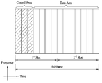
도 2는 무선 프레임(radio frame)의 구조를 예시한다. 상향/하향링크 데이터 패킷 전송은 서브프레임 단위로 이루어지며, 서브프레임은 다수의 심볼을 포함하는 시간 구간으로 정의된다. 3GPP LTE 표준에서는 FDD(Frequency Division Duplex)에 적용 가능한 타입 1 무선 프레임(radio frame) 구조와 TDD(Time Division Duplex)에 적용 가능한 타입 2의 무선 프레임 구조를 지원한다. Fig. 2 illustrates the structure of a radio frame. The uplink / downlink data packet transmission is performed in units of subframes, and a subframe is defined as a time interval including a plurality of symbols. The 3GPP LTE standard supports a
도 2(a)는 타입 1 무선 프레임의 구조를 예시한다. 하향링크 무선 프레임은 10개의 서브프레임으로 구성되고, 하나의 서브프레임은 시간 도메인(time domain)에서 2개의 슬롯(slot)으로 구성된다. 하나의 서브프레임이 전송되는 데 걸리는 시간을 TTI(transmission time interval)라 한다. 예를 들어 하나의 서브프레임의 길이는 1ms이고, 하나의 슬롯의 길이는 0.5ms 일 수 있다. 하나의 슬롯은 시간 영역에서 복수의 OFDM 심볼을 포함하고, 주파수 영역에서 다수의 자원블록(Resource Block, RB)을 포함한다. 3GPP LTE 시스템에서는 하향링크에서 OFDM을 사용하므로, OFDM 심볼이 하나의 심볼 구간을 나타낸다. OFDM 심볼은 또한 SC-FDMA 심볼 또는 심볼 구간으로 지칭될 수 있다. 자원 할당 단위로서의 자원 블록(RB)은 하나의 슬롯에서 복수의 연속적인 부반송파(subcarrier)를 포함할 수 있다. 2 (a) illustrates the structure of a
슬롯에 포함되는 OFDM 심볼의 수는 CP(Cyclic Prefix)의 구성(configuration)에 따라 달라질 수 있다. CP에는 확장 CP(extended CP)와 노멀 CP(normal CP)가 있다. 예를 들어, OFDM 심볼이 노멀 CP에 의해 구성된 경우, 하나의 슬롯에 포함되는 OFDM 심볼의 수는 7개일 수 있다. OFDM 심볼이 확장된 CP에 의해 구성된 경우, 한 OFDM 심볼의 길이가 늘어나므로, 한 슬롯에 포함되는 OFDM 심볼의 수는 노멀 CP인 경우보다 적다. 예를 들어, 확장 CP의 경우, 하나의 슬롯에 포함되는 OFDM 심볼의 수는 6개일 수 있다. 단말이 빠른 속도로 이동하는 등의 경우와 같이 채널상태가 불안정한 경우, 심볼간 간섭을 더욱 줄이기 위해 확장 CP가 사용될 수 있다.The number of OFDM symbols included in the slot may vary according to the configuration of the CP (Cyclic Prefix). CP has an extended CP and a normal CP. For example, when an OFDM symbol is configured by a normal CP, the number of OFDM symbols included in one slot may be seven. When the OFDM symbol is configured by the extended CP, since the length of one OFDM symbol is increased, the number of OFDM symbols included in one slot is smaller than that of the normal CP. For example, in the case of the extended CP, the number of OFDM symbols included in one slot may be six. If the channel state is unstable, such as when the UE moves at a high speed, an extended CP may be used to further reduce inter-symbol interference.
노멀 CP가 사용되는 경우, 슬롯은 7개의 OFDM 심볼을 포함하므로, 서브프레임은 14개의 OFDM 심볼을 포함한다. 서브프레임의 처음 최대 3 개의 OFDM 심볼은 PDCCH(physical downlink control channel)에 할당되고, 나머지 OFDM 심볼은 PDSCH(physical downlink shared channel)에 할당될 수 있다.When a normal CP is used, the slot includes 7 OFDM symbols, so that the subframe includes 14 OFDM symbols. The first three OFDM symbols at the beginning of a subframe may be allocated to a physical downlink control channel (PDCCH), and the remaining OFDM symbols may be allocated to a physical downlink shared channel (PDSCH).
도 2(b)는 타입 2 무선 프레임의 구조를 예시한다. 타입 2 무선 프레임은 2개의 하프 프레임(half frame)으로 구성된다. 하프 프레임은 4(5)개의 일반 서브프레임과 1(0)개의 스페셜 서브프레임을 포함한다. 일반 서브프레임은 UL-DL 구성(Uplink-Downlink Configuration)에 따라 상향링크 또는 하향링크에 사용된다. 서브프레임은 2개의 슬롯으로 구성된다.2 (b) illustrates the structure of a
표 1은 UL-DL 구성에 따른 무선 프레임 내 서브프레임 구성을 예시한다.Table 1 illustrates a subframe configuration in a radio frame according to the UL-DL configuration.
표에서 D는 하향링크 서브프레임을, U는 상향링크 서브프레임을, S는 스페셜(special) 서브프레임을 나타낸다. 스페셜 서브프레임은 DwPTS(Downlink Pilot TimeSlot), GP(Guard Period), UpPTS(Uplink Pilot TimeSlot)를 포함한다. DwPTS는 단말에서의 초기 셀 탐색, 동기화 또는 채널 추정에 사용된다. UpPTS는 기지국에서의 채널 추정과 단말의 상향링크 전송 동기를 맞추는 데 사용된다. 보호 구간은 상향링크와 하향링크 사이에 하향링크 신호의 다중경로 지연으로 인해 상향링크에서 생기는 간섭을 제거하기 위한 구간이다.In the table, D denotes a downlink subframe, U denotes an uplink subframe, and S denotes a special subframe. The special subframe includes a downlink pilot time slot (DwPTS), a guard period (GP), and an uplink pilot time slot (UpPTS). The DwPTS is used for initial cell search, synchronization, or channel estimation in the UE. UpPTS is used to synchronize the channel estimation at the base station and the uplink transmission synchronization of the UE. The guard interval is a period for eliminating the interference occurring in the uplink due to the multipath delay of the downlink signal between the uplink and the downlink.
무선 프레임의 구조는 예시에 불과하고, 무선 프레임에서 서브프레임의 수, 슬롯의 수, 심볼의 수는 다양하게 변경될 수 있다.The structure of the radio frame is merely an example, and the number of subframes, the number of slots, and the number of symbols in the radio frame can be variously changed.
도 3은 하향링크 슬롯의 자원 그리드를 예시한다.3 illustrates a resource grid of a downlink slot.
도 3을 참조하면, 하향링크 슬롯은 시간 도메인에서 복수의 OFDM 심볼을 포함한다. 여기에서, 하나의 하향링크 슬롯은 7개의 OFDM 심볼을 포함하고, 하나의 자원블록(RB)은 주파수 도메인에서 12개의 부반송파를 포함하는 것으로 예시되었다. 그러나, 본 발명이 이로 제한되는 것은 아니다. 자원 그리드 상에서 각각의 요소는 자원요소(Resource Element, RE)로 지칭된다. 하나의 RB는 12×7 RE들을 포함한다. 하향링크 슬롯에 포함된 RB의 개수 NDL는 하향링크 전송 대역에 의존한다. 상향링크 슬롯의 구조는 하향링크 슬롯의 구조와 동일할 수 있다.Referring to FIG. 3, the downlink slot includes a plurality of OFDM symbols in the time domain. Here, one downlink slot includes seven OFDM symbols, and one resource block (RB) is illustrated as including 12 subcarriers in the frequency domain. However, the present invention is not limited thereto. Each element on the resource grid is referred to as a Resource Element (RE). One RB includes 12 x 7 REs. The number NDL of RBs included in the downlink slot depends on the downlink transmission band. The structure of the uplink slot may be the same as the structure of the downlink slot.
도 4는 하향링크 서브프레임의 구조를 예시한다.4 illustrates a structure of a downlink subframe.
도 4를 참조하면, 서브프레임 내에서 첫 번째 슬롯의 앞에 위치한 최대 3(4)개의 OFDM 심볼이 제어 채널이 할당되는 제어 영역에 해당한다. 남은 OFDM 심볼은 PDSCH(physical downlink shared chancel)가 할당되는 데이터 영역에 해당하며, 데이터 영역의 기본 자원 단위는 RB이다. LTE 에서 사용되는 하향링크 제어 채널의 예는 PCFICH(physical control format indicator channel), PDCCH(physical downlink control channel), PHICH(physical hybrid ARQ indicator channel) 등을 포함한다. PCFICH는 서브프레임의 첫 번째 OFDM 심볼에서 전송되며 서브프레임 내에서 제어 채널의 전송에 사용되는 OFDM 심볼의 개수에 관한 정보를 나른다. PHICH는 상향링크 전송에 대한 응답이고 HARQ ACK/NACK(acknowledgment/negative-acknowledgment) 신호를 나른다. PDCCH를 통해 전송되는 제어 정보는 DCI(downlink control information)라고 지칭된다. DCI는 상향링크 또는 하향링크 스케줄링 정보 또는 임의의 단말 그룹을 위한 상향링크 전송 전력 제어 명령(Transmit Power Control Command)를 포함한다.Referring to FIG. 4, a maximum of 3 (4) OFDM symbols located in front of a first slot in a subframe corresponds to a control region to which a control channel is allocated. The remaining OFDM symbol corresponds to a data area to which a physical downlink shared chanel (PDSCH) is allocated, and the basic resource unit of the data area is RB. Examples of downlink control channels used in LTE include physical control format indicator channel (PCFICH), physical downlink control channel (PDCCH), physical hybrid ARQ indicator channel (PHICH), and the like. The PCFICH is transmitted in the first OFDM symbol of the subframe and carries information about the number of OFDM symbols used for transmission of the control channel in the subframe. The PHICH is a response to an uplink transmission and carries an HARQ ACK / NACK (acknowledgment / negative-acknowledgment) signal. The control information transmitted via the PDCCH is referred to as DCI (downlink control information). The DCI includes uplink or downlink scheduling information or an uplink transmission power control command for an arbitrary terminal group.
PDCCH를 통해 전송되는 제어 정보를 DCI(Downlink Control Information)라고 한다. DCI 포맷(format)은 상향링크용으로 포맷 0, 3, 3A, 4, 하향링크용으로 포맷 1, 1A, 1B, 1C, 1D, 2, 2A, 2B, 2C 등의 포맷이 정의되어 있다. DCI 포맷에 따라 정보 필드의 종류, 정보 필드의 개수, 각 정보 필드의 비트 수 등이 달라진다. 예를 들어, DCI 포맷은 용도에 따라 호핑 플래그(hopping flag), RB 할당(assignment), MCS(modulation coding scheme), RV(redundancy version), NDI(new data indicator), TPC(transmit power control), HARQ 프로세스 번호, PMI(precoding matrix indicator) 확인(confirmation) 등의 정보를 선택적으로 포함한다. 따라서, DCI 포맷에 따라 DCI 포맷에 정합되는 제어 정보의 사이즈(size)가 달라진다. 한편, 임의의 DCI 포맷은 두 종류 이상의 제어 정보 전송에 사용될 수 있다. 예를 들어, DCI 포맷 0/1A는 DCI 포맷 0 또는 DCI 포맷 1을 나르는데 사용되며, 이들은 플래그 필드(flag field)에 의해 구분된다.The control information transmitted through the PDCCH is called DCI (Downlink Control Information). The DCI format defines the
PDCCH는 DL-SCH(downlink shared channel)의 전송 포맷 및 자원 할당, UL-SCH(uplink shared channel)에 대한 자원 할당 정보, PCH(paging channel)에 대한 페이징 정보, DL-SCH 상의 시스템 정보(system information), PDSCH 상에서 전송되는 랜덤 접속 응답과 같은 상위-계층 제어 메시지의 자원 할당 정보, 임의의 단말 그룹 내에서 개별 단말에 대한 전송 전력 제어 명령, VoIP(voice over IP)의 활성화(activation) 등을 나른다. 제어 영역 내에서 복수의 PDCCH가 전송될 수 있다. 단말은 복수의 PDCCH를 모니터링 할 수 있다. PDCCH는 하나 또는 복수의 연속된 CCE(consecutive control channel element)의 집합(aggregation) 상에서 전송된다. CCE는 무선 채널의 상태에 따라 소정 부호율 (coding rate)의 PDCCH를 제공하기 위해 사용되는 논리적 할당 단위이다. CCE는 복수의 REG(resource element group)에 대응한다. PDCCH의 포맷 및 가용한 PDCCH의 비트 수는 CCE의 개수와 CCE에 의해 제공되는 부호율 사이의 상관 관계에 따라 결정된다. 기지국은 단말에게 전송될 DCI에 따라 PDCCH 포맷을 결정하고, CRC(cyclic redundancy check)를 제어 정보에 부가한다. CRC는 PDCCH의 소유자 또는 사용 용도에 따라 유일 식별자(RNTI(radio network temporary identifier)로 지칭됨)로 마스킹 된다. PDCCH가 특정 단말을 위한 것이면, 해당 단말의 유일 식별자(예, C-RNTI (cell-RNTI))가 CRC에 마스킹 된다. 다른 예로, PDCCH가 페이징 메시지를 위한 것이면, 페이징 지시 식별자(예, P-RNTI(paging-RNTI))가 CRC에 마스킹 된다. PDCCH가 시스템 정보 (보다 구체적으로, 후술하는 SIB(system information block))에 관한 것이면, 시스템 정보 식별자(예, SI-RNTI(system information RNTI))가 CRC에 마스킹 된다. 단말의 랜덤 접속 프리앰블의 전송에 대한 응답인, 랜덤 접속 응답을 지시하기 위해 RA-RNTI(random access-RNTI)가 CRC에 마스킹 된다.The PDCCH includes a transmission format and a resource allocation of a downlink shared channel (DL-SCH), resource allocation information on an uplink shared channel (UL-SCH), paging information on a paging channel (PCH), system information , Resource allocation information of a higher-layer control message such as a random access response transmitted on the PDSCH, transmission power control command for an individual terminal in an arbitrary terminal group, activation of VoIP (voice over IP), and the like . A plurality of PDCCHs may be transmitted within the control domain. The UE can monitor a plurality of PDCCHs. The PDCCH is transmitted on one or a plurality of consecutive control channel element (CCE) aggregations. The CCE is a logical allocation unit used to provide a PDCCH of a predetermined coding rate according to a state of a radio channel. The CCE corresponds to a plurality of resource element groups (REGs). The format of the PDCCH and the number of bits of the available PDCCH are determined according to the correlation between the number of CCEs and the code rate provided by the CCE. The base station determines the PDCCH format according to the DCI to be transmitted to the UE, and adds a CRC (cyclic redundancy check) to the control information. The CRC is masked with a unique identifier (called a radio network temporary identifier (RNTI)) according to the owner of the PDCCH or usage purpose. If the PDCCH is for a particular terminal, the unique identifier of the terminal (e.g., C-RNTI (cell-RNTI)) is masked in the CRC. In another example, if the PDCCH is for a paging message, a paging indication identifier (e.g., P-RNTI (p-RNTI)) is masked to the CRC. If the PDCCH is related to system information (more specifically, a system information block (SIB) described later), a system information identifier (e.g. SI-RNTI) is masked in the CRC. A random access-RNTI (RA-RNTI) is masked in the CRC to indicate a random access response, which is a response to the transmission of the terminal's random access preamble.
PDCCH는 DCI(Downlink Control Information)로 알려진 메시지를 나르고, DCI는 하나의 단말 또는 단말 그룹을 위한 자원 할당 및 다른 제어 정보를 포함한다. 일반적으로, 복수의 PDCCH가 하나의 서브프레임 내에서 전송될 수 있다. 각각의 PDCCH는 하나 이상의 CCE(Control Channel Element)를 이용해 전송되고, 각각의 CCE는 9세트의 4개 자원요소에 대응한다. 4개 자원요소는 REG(Resource Element Group)로 지칭된다. 4개의 QPSK 심볼이 한 REG에 맵핑된다. 참조 신호에 할당된 자원요소는 REG에 포함되지 않으며, 이로 인해 주어진 OFDM 심볼 내에서 REG의 총 개수는 셀-특정(cell-specific) 참조 신호의 존재 여부에 따라 달라진다. REG 개념(즉, 그룹 단위 맵핑, 각 그룹은 4개의 자원요소를 포함)은 다른 하향링크 제어 채널 (PCFICH 및 PHICH)에도 사용된다. 즉, REG는 제어 영역의 기본 자원 단위로 사용된다. 4개의 PDCCH 포맷이 표 2에 나열된 바와 같이 지원된다.The PDCCH carries a message known as Downlink Control Information (DCI), and the DCI includes resource allocation and other control information for one terminal or terminal group. In general, a plurality of PDCCHs may be transmitted in one subframe. Each PDCCH is transmitted using one or more CCEs (Control Channel Elements), and each CCE corresponds to nine sets of four resource elements. The four resource elements are referred to as Resource Element Groups (REGs). Four QPSK symbols are mapped to one REG. The resource element assigned to the reference signal is not included in the REG, and thus the total number of REGs within a given OFDM symbol depends on the presence of a cell-specific reference signal. The REG concept (i.e., group-by-group mapping, each group including four resource elements) is also used for other downlink control channels (PCFICH and PHICH). That is, REG is used as a basic resource unit of the control area. Four PDCCH formats are supported as listed in Table 2.
CCE들은 연속적으로 번호가 매겨지어 사용되고, 디코딩 프로세스를 단순화 하기 위해, n CCEs로 구성된 포맷을 갖는 PDCCH는 n의 배수와 동일한 수를 갖는 CCE에서만 시작될 수 있다. 특정 PDCCH의 전송을 위해 사용되는 CCE의 개수는 채널 조건에 따라 기지국에 의해 결정된다. 예를 들어, PDCCH가 좋은 하향링크 채널(예, 기지국에 가까움)를 갖는 단말을 위한 것인 경우, 하나의 CCE로도 충분할 수 있다. 그러나, 나쁜 채널(예, 셀 경계에 가까움)을 갖는 단말의 경우, 충분한 로버스트(robustness)를 얻기 위해 8개의 CCE가 사용될 수 있다. 또한, PDCCH의 파워 레벨이 채널 조건에 맞춰 조절될 수 있다.CCEs are used consecutively numbered, and in order to simplify the decoding process, a PDCCH with a format composed of n CCEs can only be started with a CCE having the same number as a multiple of n. The number of CCEs used for transmission of a specific PDCCH is determined by the base station according to the channel condition. For example, if the PDCCH is for a terminal with a good downlink channel (e.g., close to the base station), a single CCE may be sufficient. However, for a terminal with a bad channel (e. G., Near cell boundaries), eight CCEs may be used to obtain sufficient robustness. In addition, the power level of the PDCCH can be adjusted to meet the channel conditions.
LTE에 도입된 방안은 각각의 단말을 위해 PDCCH가 위치할 수 있는 제한된 세트의 CCE 위치를 정의하는 것이다. 단말이 자신의 PDCCH를 찾을 수 있는 제한된 세트의 CCE 위치는 검색 공간(Search Space, SS)으로 지칭될 수 있다. LTE에서, 검색 공간은 각각의 PDCCH 포맷에 따라 다른 사이즈를 갖는다. 또한, UE-특정(UE-specific) 및 공통(common) 검색 공간이 별도로 정의된다. UE-특정 검색 공간(UE-Specific Search Space, USS)은 각 단말을 위해 개별적으로 설정되고, 공통 검색 공간(Common Search Space, CSS)의 범위는 모든 단말에게 알려진다. UE-특정 및 공통 검색 공간은 주어진 단말에 대해 오버랩 될 수 있다. 상당히 작은 검색 공간을 가진 경우, 특정 단말을 위한 검색 공간에서 일부 CCE 위치가 할당된 경우 남는 CCE가 없기 때문에, 주어진 서브프레임 내에서 기지국은 가능한 모든 단말에게 PDCCH를 전송할 CCE 자원들을 찾지 못할 수 있다. 위와 같은 블록킹이 다음 서브프레임으로 이어질 가능성을 최소화하기 위하여 UE-특정 검색 공간의 시작 위치에 단말-특정 호핑 시퀀스가 적용된다.The approach introduced in LTE is to define a limited set of CCE locations where the PDCCH can be located for each terminal. A limited set of CCE locations where a terminal can locate its PDCCH may be referred to as a Search Space (SS). In LTE, the search space has a different size according to each PDCCH format. In addition, UE-specific and common search spaces are separately defined. The UE-Specific Search Space (USS) is set individually for each UE, and the range of the Common Search Space (CSS) is known to all UEs. The UE-specific and common search space may overlap for a given UE. In case of having a fairly small search space, since there is no remaining CCE when some CCE locations are allocated in a search space for a specific UE, the base station in the given subframe may not be able to find CCE resources to transmit PDCCH to all available UEs. In order to minimize the possibility of such blocking leading to the next sub-frame, a UE-specific hopping sequence is applied to the starting position of the UE-specific search space.
표 3은 공통 및 UE-특정 검색 공간의 사이즈를 나타낸다.Table 3 shows the sizes of common and UE-specific search spaces.
블라인드 디코딩(Blind Decoding, BD)의 총 회수에 따른 계산 부하를 통제 하에 두기 위해, 단말은 정의된 모든 DCI 포맷을 동시에 검색하도록 요구되지 않는다. 일반적으로, UE-특정 검색 공간 내에서 단말은 항상 포맷 0과 1A를 검색한다. 포맷 0과 1A는 동일 사이즈를 가지며 메시지 내의 플래그에 의해 구분된다. 또한, 단말은 추가 포맷을 수신하도록 요구될 수 있다 (예, 기지국에 의해 설정된 PDSCH 전송모드에 따라 1, 1B 또는 2). 공통 검색 공간에서 단말은 포맷 1A 및 1C를 서치한다. 또한, 단말은 포맷 3 또는 3A를 서치하도록 설정될 수 있다. 포맷 3 및 3A는 포맷 0 및 1A와 동일한 사이즈를 가지며, 단말-특정 식별자 보다는, 서로 다른 (공통) 식별자로 CRC를 스크램블함으로써 구분될 수 있다. 전송모드에 따른 PDSCH 전송 기법과, DCI 포맷들의 정보 컨텐츠를 아래에 나열하였다.In order to keep the computational load under the total number of blind decodings (BDs) under control, the terminal is not required to search all defined DCI formats simultaneously. Generally, within a UE-specific search space, the terminal always searches
전송모드(Transmission Mode, TM)Transmission Mode (TM)
● 전송모드 1: 단일 기지국 안테나포트로부터의 전송● Transmission mode 1: Transmission from single base station antenna port
● 전송모드 2: 전송 다이버시티 ● Transmission mode 2: Transmit diversity
● 전송모드 3: 개-루프 공간 다중화 ● Transmission mode 3: Open-loop space multiplexing
● 전송모드 4: 폐-루프 공간 다중화● Transmission mode 4: closed-loop spatial multiplexing
● 전송모드 5: 다중-사용자 MIMO ● Transmission mode 5: Multi-user MIMO
● 전송모드 6: 폐-루프 랭크-1 프리코딩● Transmission mode 6: closed-loop rank-1 precoding
● 전송모드 7: 단일-안테나 포트(포트 5) 전송● Transmission mode 7: Single-antenna port (port 5) transmission
● 전송모드 8: 이중 레이어 전송(포트 7 및 8) 또는 단일-안테나 포트(포트 7 또는 8) 전송● Transmission Mode 8: Transmission of dual-layer transmission (
● 전송모드 9: 최대 8개의 레이어 전송(포트 7 ~14) 또는 단일-안테나 포트(포트 7 또는 8) 전송● Transmission mode 9: Transmission of up to 8 layers (
DCI 포맷DCI format
● 포맷 0: PUSCH 전송 (상향링크)을 위한 자원 그랜트● Format 0: Resource Grant for PUSCH transmission (uplink)
● 포맷 1: 단일 코드워드 PDSCH 전송 (전송모드 1, 2 및 7)을 위한 자원 할당● Format 1: Resource allocation for single codeword PDSCH transmission (
● 포맷 1A: 단일 코드워드 PDSCH (모든 모드)를 위한 자원 할당의 콤팩트 시그널링● Format 1A: Compact signaling of resource allocation for single codeword PDSCH (all modes)
● 포맷 1B: 랭크-1 폐-루프 프리코딩을 이용하는 PDSCH (모드 6)를 위한 콤팩트 자원 할당Format 1B: Compact resource allocation for PDSCH (mode 6) using rank-1 closed-loop precoding
● 포맷 1C: PDSCH (예, 페이징/브로드캐스트 시스템 정보)를 위한 매우 콤팩트한 자원 할당● Format 1C: Very compact resource allocation for PDSCH (eg, paging / broadcast system information)
● 포맷 1D: 다중-사용자 MIMO를 이용하는 PDSCH (모드 5)를 위한 콤팩트 자원 할당● Format 1D: Compact resource allocation for PDSCH (mode 5) using multi-user MIMO
● 포맷 2: 폐-루트 MIMO 동작의 PDSCH (모드 4)를 위한 자원 할당Format 2: Closed - Resource allocation for PDSCH (mode 4) of root MIMO operation
● 포맷 2A: 개-루프 MIMO 동작의 PDSCH (모드 3)를 위한 자원 할당Format 2A: resource allocation for PDSCH (mode 3) of open-loop MIMO operation
● 포맷 3/3A: PUCCH 및 PUSCH를 위해 2-비트/1-비트 파워 조정 값을 갖는 파워 콘트롤 커맨드●
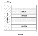
도 5는 EPDCCH를 예시한다. EPDCCH는 LTE-A에서 추가로 도입된 채널이다.Figure 5 illustrates EPDCCH. EPDCCH is an additional channel introduced in LTE-A.
도 5를 참조하면, 서브프레임의 제어 영역(도 4 참조)에는 기존 LTE에 따른 PDCCH(편의상, Legacy PDCCH, L-PDCCH)가 할당될 수 있다. 도면에서 L-PDCCH 영역은 L-PDCCH가 할당될 수 있는 영역을 의미한다. 한편, 데이터 영역(예, PDSCH를 위한 자원 영역) 내에 PDCCH가 추가로 할당될 수 있다. 데이터 영역에 할당된 PDCCH를 EPDCCH라고 지칭한다. 도시된 바와 같이, EPDCCH를 통해 제어 채널 자원을 추가 확보함으로써, L-PDCCH 영역의 제한된 제어 채널 자원으로 인한 스케줄링 제약을 완화할 수 있다. L-PDCCH와 마찬가지로, EPDCCH는 DCI를 나른다. 예를 들어, EPDCCH는 하향링크 스케줄링 정보, 상향링크 스케줄링 정보를 나를 수 있다. 예를 들어, 단말은 EPDCCH를 수신하고 EPDCCH에 대응되는 PDSCH를 통해 데이터/제어 정보를 수신할 수 있다. 또한, 단말은 EPDCCH를 수신하고 EPDCCH에 대응되는 PUSCH를 통해 데이터/제어 정보를 송신할 수 있다. 셀 타입에 따라 EPDCCH/PDSCH는 서브프레임의 첫 번째 OFDM 심볼부터 할당될 수 있다. 특별히 구별하지 않는 한, 본 명세서에서 PDCCH는 L-PDCCH와 EPDCCH를 모두 포함한다.Referring to FIG. 5, a PDCCH (Legacy PDCCH, L-PDCCH) may be allocated to a control region of a subframe (see FIG. 4) according to existing LTE. In the figure, an L-PDCCH region refers to an area to which an L-PDCCH can be allocated. On the other hand, a PDCCH can be additionally allocated in a data area (e.g., a resource area for PDSCH). The PDCCH allocated to the data area is referred to as EPDCCH. As shown, the scheduling constraint due to the limited control channel resources in the L-PDCCH region can be relaxed by securing additional control channel resources through the EPDCCH. Like the L-PDCCH, the EPDCCH carries the DCI. For example, the EPDCCH may carry downlink scheduling information and uplink scheduling information. For example, the terminal may receive the EPDCCH and receive the data / control information on the PDSCH corresponding to the EPDCCH. Also, the UE can receive the EPDCCH and transmit the data / control information through the PUSCH corresponding to the EPDCCH. Depending on the cell type, the EPDCCH / PDSCH can be allocated from the first OFDM symbol of the subframe. Unless otherwise specified, the PDCCH herein includes both L-PDCCH and EPDCCH.
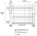
도 6은 LTE(-A)에서 사용되는 상향링크 서브프레임의 구조를 예시한다.6 illustrates a structure of an uplink subframe used in LTE (-A).
도 6을 참조하면, 서브프레임(500)은 두 개의 0.5ms 슬롯(501)으로 구성된다. 보통(Normal) 순환 전치(Cyclic Prefix, CP)의 길이를 가정할 때, 각 슬롯은 7개의 심볼(502)로 구성되며 하나의 심볼은 하나의 SC-FDMA 심볼에 대응된다. 자원 블록(Resource Block, RB)(503)은 주파수 영역에서 12개의 부반송파, 그리고 시간 영역에서 한 슬롯에 해당되는 자원 할당 단위이다. LTE(-A)의 상향링크 서브프레임의 구조는 크게 데이터 영역(504)과 제어 영역(505)으로 구분된다. 데이터 영역은 각 단말로 전송되는 음성, 패킷 등의 데이터를 송신함에 있어 사용되는 통신 자원을 의미하며 PUSCH(Physical Uplink Shared Channel)을 포함한다. 제어 영역은 상향링크 제어 신호, 예를 들어 각 단말로부터의 하향링크 채널 품질보고, 하향링크 신호에 대한 수신 ACK/NACK, 상향링크 스케줄링 요청 등을 전송하는데 사용되는 통신 자원을 의미하며 PUCCH(Physical Uplink Control Channel)을 포함한다. 사운딩 참조 신호(Sounding Reference Signal, SRS)는 하나의 서브프레임에서 시간 축 상에서 가장 마지막에 위치하는 SC-FDMA 심볼을 통하여 전송된다. 동일한 서브프레임의 마지막 SC-FDMA로 전송되는 여러 단말의 SRS들은 주파수 위치/시퀀스에 따라 구분이 가능하다. SRS는 상향링크 채널 상태를 기지국에게 전송하는데 사용되며, 상위 계층(예, RRC 계층)에 의해 설정된 서브프레임 주기/오프셋에 따라 주기적으로 전송되거나, 기지국의 요청에 따라 비주기적으로 전송된다.Referring to FIG. 6, the
도 7은 상향링크-하향링크 프레임 타이밍 관계를 예시한다.7 illustrates an uplink-downlink frame timing relationship.
도 7을 참조하면, 상향링크 무선 프레임 i의 전송은 해당 하향링크 무선 프레임보다 (NTA+NTAoffset)*Ts초 이전에 시작된다. LTE 시스템의 경우, 0≤NTA≤20512이고, FDD에서 NTAoffset=0이며, TDD에서 NTAoffset=624이다. NTAoffset 값은 기지국과 단말이 사전에 인지하고 있는 값이다. 랜덤 접속 과정에서 타이밍 어드밴스 명령을 통해 NTA이 지시되면, 단말은 UL 신호(예, PUCCH/PUSCH/SRS)의 전송 타이밍을 위의 수식을 통해 조정한다. UL 전송 타이밍은 16Ts의 배수로 설정된다. 타이밍 어드밴스 명령은 현 UL 타이밍을 기준으로 UL 타이밍의 변화를 지시한다. 랜덤 접속 응답 내의 타이밍 어드밴스 명령(TA)은 11-비트로서 TA는 0,1,2,…,1282의 값을 나타내고 타이밍 조정 값(NTA)은 NTA=TA*16으로 주어진다. 그 외의 경우, 타이밍 어드밴스 명령(TA)은 6-비트로서 TA는 0,1,2,…,63의 값을 나타내고 타이밍 조정 값(NTA)은 NTA,new=NTA,old+(TA-31)*16으로 주어진다. 서브프레임 n에서 수신된 타이밍 어드밴스 명령은 서브프레임 n+6부터 적용된다. FDD의 경우, 도시된 바와 같이, UL 서브프레임 n의 전송 시점은 DL 서브프레임 n의 시작 시점을 기준으로 앞당겨진다. 반면, TDD의 경우, UL 서브프레임 n의 전송 시점은 DL 서브프레임 n+1의 종료 시점을 기준으로 앞당겨진다(미도시).Referring to FIG. 7, the transmission of the uplink radio frame i starts before (N TA + N TAoffset ) * T s seconds earlier than the corresponding downlink radio frame. For LTE systems, 0? N TA? 20512, N TAoffset = 0 in FDD, and N TAoffset = 624 in TDD. The N TAoffset value is a value previously recognized by the BS and the UE. If N TA is indicated through the timing advance command in the random access procedure, the UE adjusts the transmission timing of the UL signal (e.g., PUCCH / PUSCH / SRS) through the above equation. The UL transmission timing is set to a multiple of 16T s . The timing advance command indicates a change in UL timing with reference to the current UL timing. The timing advance instruction (T A ) in the random access response is 11-bit, and T A is 0, 1, 2, ... , 1282, and the timing adjustment value NTA is given by N TA = T A * 16. Otherwise, the timing advance instruction (T A ) is 6-bit and T A is 0, 1, 2, ... , 63 and the timing adjustment value (N TA ) is given by N TA, new = N TA, old + (T A -31) * 16. The timing advance command received in subframe n is applied from subframe n + 6. In the case of FDD, as shown, the transmission time of UL subframe n is advanced based on the start time of DL subframe n. On the other hand, in the case of TDD, the transmission time of the UL subframe n is advanced (not shown) based on the end time of the DL subframe n + 1.
다음으로 HARQ (Hybrid Automatic Repeat reQuest)에 대해 설명한다. 무선 통신 시스템에서 상향/하향링크로 전송해야 할 데이터가 있는 단말이 다수 존재할 때, 기지국은 전송 단위 시간(Transmission Time Interval: TTI)(예, 서브프레임) 마다 데이터를 전송할 단말을 선택한다. 다중 반송파 및 이와 유사하게 운영되는 시스템에서 기지국은 TTI마다 상향/하향링크로 데이터를 전송할 단말들을 선택하고 해당 단말이 데이터 전송을 위해 사용하는 주파수 대역도 함께 선택하여 준다. Next, HARQ (Hybrid Automatic Repeat reQuest) will be described. In a wireless communication system, when there are a plurality of terminals having data to be transmitted in the uplink / downlink, the base station selects a terminal to transmit data for each transmission time interval (TTI) (e.g., subframe). In a multi-carrier and similarly operated system, a base station selects terminals to transmit data in uplink / downlink for each TTI, and also selects a frequency band used by the terminal for data transmission.
상향링크를 기준으로 설명하면, 단말들은 상향링크로 참조 신호(또는 파일럿)를 전송하고, 기지국은 단말들로부터 전송된 참조 신호를 이용하여 단말들의 채널 상태를 파악하여 TTI마다 각각의 단위 주파수 대역에서 상향링크로 데이터를 전송할 단말들을 선택한다. 기지국은 이러한 결과를 단말에게 알려준다. 즉, 기지국은 특정 TTI에 상향링크 스케줄링 된 단말에게 특정 주파수 대역을 이용하여 데이터를 보내라는 상향링크 할당 메시지(assignment message)를 전송한다. 상향링크 할당 메시지는 UL 그랜트(grant)라고도 지칭된다. 단말은 상향링크 할당 메시지에 따라 데이터를 상향링크로 전송한다. 상향링크 할당 메시지는 단말 ID(UE Identity), RB 할당 정보, MCS(Modulation and Coding Scheme), RV(Redundancy Version) 버전, 신규 데이터 지시자(New Data indication, NDI) 등을 포함할 수 있다. Referring to the uplink, the UEs transmit a reference signal (or pilot) in the uplink, and the BS determines the channel state of the UEs using the reference signal transmitted from the UEs, And selects the terminals to transmit data on the uplink. The base station informs the terminal of the result. That is, the base station transmits an uplink assignment message to transmit data using a specific frequency band to a UE scheduled in a specific TTI. The UL allocation message is also referred to as an UL grant. The UE transmits data on the uplink according to the uplink assignment message. The uplink assignment message may include a UE ID, RB allocation information, a Modulation and Coding Scheme (MCS), a Redundancy Version (RV) version, a New Data Indication (NDI), and the like.
동기 비적응(Synchronous non-adaptive) HARQ 방식의 경우, 재전송 시간은 시스템적으로 약속되어 있다(예, NACK 수신 시점으로부터 4 서브프레임 후). 따라서, 기지국이 단말에게 보내는 UL 그랜트 메시지는 초기 전송 시에만 보내면 되고, 이후의 재전송은 ACK/NACK 신호(예, PHICH 신호)에 의해 이뤄진다. 반면, 비동기 적응(Asynchronous adaptive) HARQ 방식의 경우, 재전송 시간이 서로 약속되어 있지 않으므로, 기지국이 단말에게 재전송 요청 메시지를 보내야 한다. 또한, 재전송을 위한 주파수 자원이나 MCS가 전송 시점마다 달라지므로, 재전송 요청 메시지는 단말 ID, RB 할당 정보, HARQ 프로세스 ID/번호, RV, NDI 정보를 포함할 수 있다. In the case of the synchronous non-adaptive HARQ scheme, the retransmission time is systematically promised (for example, after 4 subframes from the NACK reception time). Therefore, the UL grant message that the base station sends to the UE can be transmitted only at the initial transmission, and the subsequent retransmission is performed by the ACK / NACK signal (e.g., the PHICH signal). On the other hand, in the asynchronous adaptive HARQ scheme, since the retransmission times are not agreed with each other, the base station must send a retransmission request message to the UE. The retransmission request message may include the UE ID, RB allocation information, HARQ process ID / number, RV, and NDI information because the frequency resource and the MCS for retransmission are changed at each transmission time.
도 8은 LTE(-A) 시스템에서 UL HARQ 동작을 예시한다. LTE(-A) 시스템에서 UL HARQ 방식은 동기 비적응 HARQ를 사용한다. 8 채널 HARQ를 사용할 경우 HARQ 프로세스 번호는 0~7로 주어진다. TTI(예, 서브프레임) 마다 하나의 HARQ 프로세스가 동작한다. 도 8을 참조하면, 기지국(110)은 PDCCH를 통해 UL 그랜트를 단말(120)에게 전송한다(S600). 단말(120)은 UL 그랜트를 수신한 시점(예, 서브프레임 0)으로부터 4 서브프레임 이후(예, 서브프레임 4)에 UL 그랜트에 의해 지정된 RB 및 MCS를 이용해 기지국(S110)에게 상향링크 데이터를 전송한다(S602). 기지국(110)은 단말(120)로부터 수신한 상향링크 데이터를 복호한 뒤 ACK/NACK을 생성한다. 상향링크 데이터에 대한 복호가 실패한 경우, 기지국(110)은 단말(120)에게 NACK을 전송한다(S604). 단말(120)은 NACK을 수신한 시점으로부터 4 서브프레임 이후에 상향링크 데이터를 재전송한다(S606). 상향링크 데이터의 초기 전송과 재전송은 동일한 HARQ 프로세서가 담당한다(예, HARQ 프로세스 4). ACK/NACK 정보는 PHICH를 통해 전송될 수 있다.Figure 8 illustrates UL HARQ operation in an LTE (-A) system. In the LTE (-A) system, the UL HARQ scheme uses synchronous non-adaptive HARQ. When 8-channel HARQ is used, the HARQ process number is given as 0 to 7. One HARQ process operates for each TTI (e.g., subframe). Referring to FIG. 8, the
도 9는 캐리어 병합(Carrier Aggregation, CA) 통신 시스템을 예시한다.Figure 9 illustrates a Carrier Aggregation (CA) communication system.
도 9를 참조하면, 복수의 상/하향링크 콤포넌트 캐리어(Component Carrier, CC)들을 모아서 더 넓은 상/하향링크 대역폭을 지원할 수 있다. 각각의 CC들은 주파수 영역에서 서로 인접하거나 비-인접할 수 있다. 각 콤포넌트 캐리어의 대역폭은 독립적으로 정해질 수 있다. UL CC의 개수와 DL CC의 개수가 다른 비대칭 캐리어 병합도 가능하다. 한편, 제어 정보는 특정 CC를 통해서만 송수신 되도록 설정될 수 있다. 이러한 특정 CC를 프라이머리 CC로 지칭하고, 나머지 CC를 세컨더리 CC로 지칭할 수 있다. 일 예로, 크로스-캐리어 스케줄링(cross-carrier scheduling) (또는 크로스-CC 스케줄링)이 적용될 경우, 하향링크 할당을 위한 PDCCH는 DL CC#0으로 전송되고, 해당 PDSCH는 DL CC#2로 전송될 수 있다. 용어 “콤포넌트 캐리어”는 등가의 다른 용어(예, 캐리어, 셀 등)로 대체될 수 있다.Referring to FIG. 9, a plurality of uplink / downlink component carriers (CCs) may be aggregated to support a wider uplink / downlink bandwidth. Each CC may be adjacent or non-adjacent to one another in the frequency domain. The bandwidth of each component carrier can be determined independently. It is also possible to combine asymmetric carriers with different numbers of UL CCs and DL CCs. On the other hand, the control information can be set to be transmitted and received only through a specific CC. This particular CC may be referred to as a primary CC and the remaining CC as a secondary CC. For example, when cross-carrier scheduling (or cross-CC scheduling) is applied, the PDCCH for downlink allocation is transmitted to
크로스-CC 스케줄링을 위해, CIF(carrier indicator field)가 사용된다. PDCCH 내에 CIF의 존재 또는 부재를 위한 설정이 반-정적으로 단말-특정 (또는 단말 그룹-특정)하게 상위 계층 시그널링(예, RRC 시그널링)에 의해 이네이블(enable) 될 수 있다. PDCCH 전송의 기본 사항이 아래와 같이 정리될 수 있다.For cross-CC scheduling, a carrier indicator field (CIF) is used. The configuration for the presence or absence of the CIF in the PDCCH may be enabled semi-statically by higher layer signaling (e.g., RRC signaling) in a terminal-specific (or terminal group-specific) manner. The basics of PDCCH transmission can be summarized as follows.
■ CIF 디스에이블드(disabled): DL CC 상의 PDCCH는 동일 DL CC 상의 PDSCH 자원 및 단일의 링크된 UL CC 상에서의 PUSCH 자원을 할당한다.CIF Disable: The PDCCH on the DL CC allocates the PDSCH resources on the same DL CC and the PUSCH resources on the single linked UL CC.
● No CIF ● No CIF
■ CIF 이네이블드(enabled): DL CC 상의 PDCCH는 CIF를 이용하여 복수의 병합된 DL/UL CC들 중 한 DL/UL CC 상의 PDSCH 또는 PUSCH 자원을 할당할 수 있다.CIF enabled: The PDCCH on DL CC can allocate PDSCH or PUSCH resources on one DL / UL CC among a plurality of merged DL / UL CCs using CIF.
● CIF를 갖도록 확장된 LTE DCI 포맷 ● Extended LTE DCI format with CIF
- CIF (설정될 경우)는 고정된 x-비트 필드 (예, x=3) - CIF (if set) is a fixed x-bit field (eg x = 3)
- CIF (설정될 경우) 위치는 DCI 포맷 사이즈와 관계 없이 고정됨 - CIF (if set) position is fixed regardless of DCI format size
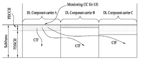
CIF 존재 시, 기지국은 단말 측에서의 BD 복잡도를 낮추기 위해 모니터링 DL CC (세트)를 할당할 수 있다. PDSCH/PUSCH 스케줄링 위해, 단말은 해당 DL CC에서만 PDCCH의 검출/디코딩을 수행할 수 있다. 또한, 기지국은 모니터링 DL CC (세트)를 통해서만 PDCCH를 전송할 수 있다. 모니터링 DL CC 세트는 단말-특정, 단말-그룹-특정 또는 셀-특정 방식으로 세팅될 수 있다.In the presence of the CIF, the BS may allocate a monitoring DL CC (set) to lower the BD complexity on the UE side. For PDSCH / PUSCH scheduling, the UE can perform PDCCH detection / decoding only in the corresponding DL CC. In addition, the base station can transmit the PDCCH only through the monitoring DL CC (set). The monitoring DL CC set may be set in a UE-specific, UE-group-specific or cell-specific manner.
도 10은 복수의 캐리어가 병합된 경우의 스케줄링을 예시한다. 3개의 DL CC가 병합되었다고 가정한다. DL CC A가 PDCCH CC로 설정되었다고 가정한다. DL CC A~C는 서빙 CC, 서빙 캐리어, 서빙 셀 등으로 지칭될 수 있다. CIF가 디스에이블 되면, 각각의 DL CC는 LTE PDCCH 규칙에 따라 CIF 없이 자신의 PDSCH를 스케줄링 하는 PDCCH만을 전송할 수 있다(논-크로스-CC 스케줄링). 반면, 단말-특정 (또는 단말-그룹-특정 또는 셀-특정) 상위 계층 시그널링에 의해 CIF가 이네이블 되면, 특정 CC(예, DL CC A)는 CIF를 이용하여 DL CC A의 PDSCH를 스케줄링 하는 PDCCH뿐만 아니라 다른 CC의 PDSCH를 스케줄링 하는 PDCCH도 전송할 수 있다(크로스-CC 스케줄링). 반면, DL CC B/C에서는 PDCCH가 전송되지 않는다.FIG. 10 illustrates scheduling when a plurality of carriers are merged. It is assumed that three DL CCs are merged. It is assumed that DL CC A is set to PDCCH CC. DL CC A-C may be referred to as serving CC, serving carrier, serving cell, and the like. If the CIF is disabled, each DL CC may send only a PDCCH that schedules its PDSCH without CIF (non-cross-CC scheduling) according to the LTE PDCCH rules. On the other hand, when the CIF is enabled by the UE-specific (or UE-group-specific or cell-specific) higher layer signaling, the specific CC (e.g., DL CC A) schedules the PDSCH of the DL CC A using the CIF (PDCCH) as well as PDCCHs scheduling PDSCHs of other CCs (cross-CC scheduling). On the other hand, in the DL CC B / C, the PDCCH is not transmitted.
더욱 많은 통신 기기들이 더욱 큰 통신 용량을 요구하게 됨에 따라 차기 무선 통신 시스템에서 제한된 주파수 대역의 효율적 활용은 점점 더 중요한 요구가 되고 있다. 기본적으로 주파수 스펙트럼은 면허 밴드(licensed band)와 비면허 밴드(unlicensed band)로 나뉜다. 면허 밴드는 특정 용도를 위해 점유된 주파수 밴드를 포함한다. 예를 들어, 면허 밴드는 셀룰러 통신(예, LTE 주파수 밴드)을 위해 정부가 할당한 주파수 밴드를 포함한다. 비면허 밴드는 공공 용도를 위해 점유된 주파수 밴드이며 라이센스-프리 밴드라고도 지칭된다. 비면허 밴드는 전파 규제에 대한 조건을 만족하면 허가나 신고 없이 누구나 사용할 수 있다. 비면허 밴드는 다른 무선국의 통신을 저해하지 아니하는 출력 범위에서 특정 구역이나 건물 내 등의 가까운 거리에서 누구나 사용할 목적으로 분배 또는 지정되었으며, 무선 리모컨, 무선 전력 전송, 무선랜(WiFi) 등에 다양하게 사용되고 있다.As more and more communication devices require greater communication capacity, efficient utilization of limited frequency bands in future wireless communication systems is becoming an increasingly important requirement. Basically, the frequency spectrum is divided into the licensed band and the unlicensed band. License bands include frequency bands occupied for specific uses. For example, the license band includes government allocated frequency bands for cellular communications (eg, LTE frequency bands). The license-exempt band is the occupied frequency band for public use and is also referred to as the license-free band. The license-exempt band can be used by anyone without permission or declaration if they meet the requirements for radio regulations. The license-exempt band is distributed or designated for use by anyone at a close range, such as within a specific area or building, in an output range that does not interfere with the communication of other stations, and is widely used for wireless remote control, wireless power transmission, WiFi have.
LTE 시스템과 같은 셀룰라 통신 시스템도 기존의 WiFi 시스템이 사용하는 비면허 대역(예, 2.4GHz, 5GHz 대역)을 트래픽 오프로딩에 활용하는 방안을 검토 중이다. 기본적으로 비면허 대역은 각 통신 노드 간의 경쟁을 통해 무선 송수신을 하는 방식을 가정하므로 각 통신 노드가 신호를 전송하기 전에 채널 센싱(Channel Sensing, CS)을 수행하여 다른 통신 노드가 신호 전송을 하지 않음을 확인할 것을 요구하고 있다. 이를 CCA(Clear Channel Assessment)라고 부르며, LTE 시스템의 기지국이나 단말도 비면허 대역에서의 신호 전송을 위해서는 CCA를 수행해야 할 수 있다. 편의상, LTE-A 시스템에 사용되는 비면허 대역을 LTE-U 밴드/대역이라고 지칭한다. 또한, LTE-A 시스템의 기지국이나 단말이 신호를 전송할 때에 WiFi 등 다른 통신 노드들도 CCA를 수행하여 간섭을 일으키지 않아야 한다. 예를 들어, WiFi 표준(801.11ac)에서 CCA 임계치는 non-WiFi 신호에 대하여 -62dBm, WiFi 신호에 대하여 -82dBm으로 규정되어 있다. 따라서, WiFi 이외의 신호가 -62dBm 이상의 전력으로 수신되면, STA(Station)/AP(Access Point)는 간섭을 일으키지 않기 위해 신호 전송을 하지 않는다. WiFi 시스템에서 STA/AP는 CCA 임계치 이상의 신호를 4us 이상 검출하지 않으면 CCA를 수행하고 신호 전송을 수행할 수 있다.Cellular communication systems such as LTE systems are also exploring ways to utilize the license-exempt band (eg 2.4 GHz, 5 GHz band) used by existing WiFi systems for traffic offloading. Basically, the license-exempted band is assumed to transmit and receive wirelessly through competition between each communication node. Therefore, each communication node performs channel sensing (CS) before transmitting a signal, To be confirmed. This is referred to as CCA (Clear Channel Assessment), and a base station or a terminal of an LTE system may need to perform a CCA for signal transmission in the license-exempt band. For convenience, the license-exempt band used in the LTE-A system is referred to as the LTE-U band / band. In addition, when a base station or a terminal of an LTE-A system transmits a signal, other communication nodes such as WiFi should also perform CCA to prevent interference. For example, in the WiFi standard (801.11ac), the CCA threshold is specified to be -62 dBm for non-WiFi signals and -82 dBm for WiFi signals. Therefore, when a signal other than WiFi is received at a power of -62 dBm or more, the STA (Station) / AP (Access Point) does not transmit a signal in order not to cause interference. In the WiFi system, the STA / AP can perform the CCA and carry out the signal transmission if it detects no more than 4us of the signal exceeding the CCA threshold value.
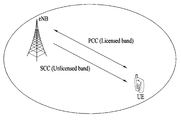
도 11은 면허 밴드와 비면허 밴드의 캐리어 병합을 예시한다. 도 11을 참조하면, 면허 밴드(이하, LTE-A 밴드, L-밴드)와 비면허 밴드(이하, LTE-U 밴드, U-밴드)의 반송파 집성 상황 하에서 기지국이 단말에게 신호를 송신하거나 단말이 기지국으로 신호를 송신할 수 있다. 여기서, 면허 대역의 중심 반송파 혹은 주파수 자원은 PCC 혹은 PCell로 해석되고, 비면허 대역의 중심 반송파 혹은 주파수 자원은 SCC 혹은 SCell로 해석될 수 있다.Figure 11 illustrates the merging of carriers in license and license-exempt bands. 11, when a base station transmits a signal to a mobile station under a carrier aggregation state of a license band (LTE-A band, L-band) and a license-exempt band (hereinafter, LTE-U band and U-band) A signal can be transmitted to the base station. Here, the center carrier or frequency resource of the license band is interpreted as PCC or PCell, and the center carrier or frequency resource of the license-exempted band can be interpreted as SCC or SCell.
도 12~13은 비면허 밴드 내에서 자원을 점유하는 방법을 예시한다. LTE-U 밴드에서 기지국과 단말이 통신을 수행하기 위해서는, LTE-A와 무관한 다른 통신(예, WiFi) 시스템과의 경쟁을 통해서 해당 대역을 특정 시간 구간 동안 점유/확보할 수 있어야 한다. 편의상, LTE-U 밴드에서 셀룰러 통신을 위해 점유/확보된 시간 구간을 RRP(Reserved Resource Period)라고 칭한다. RRP 구간을 확보하기 위해 여러 방법이 존재할 수 있다. 일 예로, WiFi 등 다른 통신 시스템 장치들이 무선 채널이 비지(busy)하다고 인식할 수 있도록 RRP 구간 내에서 특정 점유 신호를 전송할 수 있다. 예를 들어, RRP 구간 동안 특정 전력 레벨 이상의 신호가 끊임없이 전송되도록 하기 위해, 기지국은 RRP 구간 내에서 RS 및 데이터 신호를 지속적으로 전송할 수 있다. 기지국이 LTE-U 밴드 상에서 점유하고자 하는 RRP 구간을 미리 결정하였다면, 기지국은 단말한테 이를 미리 알려줌으로써 단말로 하여금 지시된 RRP 구간 동안 통신 송/수신 링크를 유지하도록 할 수 있다. 단말에게 RRP 구간 정보를 알려주는 방식으로는 반송파 집성 형태로 연결되어 있는 다른 CC (예, LTE-A 밴드)를 통해서 RRP 시간 구간 정보를 전달해주는 방식이 가능하다. Figures 12-13 illustrate how to occupy resources within a license-exempt band. In order for a base station and a terminal to communicate with each other in an LTE-U band, it is necessary to compete with other communication systems (e.g., WiFi) independent of LTE-A to occupy / secure the corresponding band for a specific time period. For convenience, the time period occupied / secured for cellular communication in the LTE-U band is called a reserved resource period (RRP). There are several ways to secure the RRP interval. For example, other communication system devices, such as WiFi, may transmit a specific occupancy signal within the RRP interval to recognize that the wireless channel is busy. For example, in order for a signal above a certain power level to be transmitted constantly during the RRP interval, the base station may continuously transmit the RS and data signals within the RRP interval. If the base station determines in advance an RRP interval to be occupied on the LTE-U band, the base station informs the UE of the RRP interval in advance so that the UE can maintain the communication transmission / reception link during the indicated RRP interval. In a method of informing the UE of the RRP interval information, it is possible to transmit the RRP time interval information through another CC (e.g., LTE-A band) connected in a carrier aggregation form.
일 예로, M개의 연속된 SF로 구성된 RRP 구간을 설정할 수 있다. 이와 달리, 하나의 RRP 구간은 불연속적으로 존재하는 SF 세트로 설정될 수도 있다(미도시). 여기서, M 값 및 M개의 SF 용도를 사전에 기지국이 단말에게 상위 계층(예, RRC 또는 MAC) 시그널링 (using PCell)이나 물리 제어/데이타 채널을 통해 알려줄 수 있다. RRP 구간의 시작 시점은 상위 계층(예, RRC 또는 MAC) 시그널링에 의해 주기적으로 설정될 수 있다. 또한, RRP 시작 지점을 SF #n 으로 설정고하고자 할 때, SF #n에서 혹은 SF #(n-k)에서 물리 계층 시그널링(예, (E)PDCCH)을 통해 RRP 구간의 시작 지점이 지정될 수 있다. k는 양의 정수(예, 4)이다.As an example, an RRP interval composed of M consecutive SFs can be set. Alternatively, one RRP section may be set to a discontinuously existing SF set (not shown). Here, the M-th value and the M SF usage can be informed to the UE by the base station in advance through an upper layer (e.g., RRC or MAC) signaling (using PCell) or a physical control / data channel. The start time of the RRP interval may be periodically set by signaling of an upper layer (e.g., RRC or MAC). Further, when it is desired to set the RRP start point to SF #n, the starting point of the RRP interval may be specified in SF # n or in physical layer signaling (e.g., (E) PDCCH) in SF # (nk) . k is a positive integer (e.g., 4).
RRP는 SF 바운더리 및 SF 번호/인덱스가 PCell과 일치되게 구성되거나(이하, aligned-RRP)(도 12), SF 바운더리 또는 SF 번호/인덱스가 PCell과 일치되지 않은 형태까지 지원되도록 구성될 수 있다(이하, 플로팅(floating)-RRP)(도 13). 본 발명에서 셀간 SF 바운더리가 일치된다는 것은, 서로 다른 2개 셀의 SF 바운더리간 간격이 특정 시간(예, CP 길이, 혹은 X us (X≥0)) 이하인 것을 의미할 수 있다. 또한, 본 발명에서 PCell은 시간 (및/또는 주파수) 동기 관점에서 UCell의 SF (및/또는 심볼) 바운더리를 결정하기 위해 참조하는 셀을 의미할 수 있다.RRP may be configured such that SF boundary and SF number / index are configured to match PCell (hereafter aligned-RRP) (FIG. 12), SF boundary or SF number / index is not matched to PCell Floating-RRP) (Fig. 13). The fact that the inter-cell SF boundary is consistent in the present invention may mean that the interval between the SF boundaries of two different cells is equal to or less than a specific time (e.g., CP length or X us (X? 0)). Also, PCell in the present invention may refer to a cell that is referenced to determine the SF (and / or symbol) boundary of the UCell in terms of time (and / or frequency) synchronization.
경쟁 기반의 임의 접속 방식으로 동작하는 비면허 대역에서의 다른 동작 예로, 기지국은 데이타 송수신 전에 먼저 캐리어 센싱을 수행할 수 있다. SCell의 현재 채널 상태가 아이들이라고 판단되면, 기지국은 PCell (LTE-A 밴드) 혹은 SCell (LTE-U 밴드)을 통해 스케줄링 그랜트(예, (E)PDCCH)를 전송하고, SCell 상에서 데이터 송수신을 시도할 수 있다. 편의상, 면허 밴드에서 동작하는 서빙 셀(예, PCell, SCell)을 LCell로 정의하고, LCell의 중심 주파수를 (DL/UL) LCC라고 정의한다. 비면허 밴드에서 동작하는 서빙 셀(예, SCell)을 UCell로 정의하고, UCell의 중심 주파수를 (DL/UL) UCC로 정의한다. 또한, UCell이 동일 셀로부터 스케줄링 되는 경우와 UCell이 다른 셀(예, PCell)로부터 스케줄링 되는 경우를 각각 self-CC 스케줄링과 cross-CC 스케줄링으로 지칭한다.Another example of operation in a license-exempt band operating in a contention-based random access scheme is that the base station can perform carrier sensing before data is transmitted and received. If it is determined that the current channel status of SCell is idle, the base station transmits a scheduling grant (e.g., (E) PDCCH) via PCell (LTE-A band) or SCell (LTE-U band) can do. For convenience, the serving cell (eg, PCell, SCell) operating in the license band is defined as LCell and the center frequency of the LCell is defined as (DL / UL) LCC. The serving cell (eg, SCell) operating in the license-exempt band is defined as UCell, and the center frequency of UCell is defined as (DL / UL) UCC. In addition, the case where the UCell is scheduled from the same cell and the case where the UCell is scheduled from another cell (e.g., PCell) are referred to as self-CC scheduling and cross-CC scheduling, respectively.
실시예: LTE LAA(Licensed Assisted Access)에서의 신호 송수신Embodiment: Signal transmission / reception in LTE LAA (Licensed Assisted Access)
기존 LTE 시스템에는 각각의 DL/UL 그랜트 DCI가 단일 DL/UL SF를 통해 전송되는 하나의 DL/UL 데이터 채널(예, PDSCH/PUSCH)을 스케줄링 하는 single-SF 스케줄링 방식이 적용된다. 반면, LTE-A 이후의 시스템에서는 데이터 스케줄링에 수반되는 DCI 오버헤드를 줄이기 위하여 하나의 DL/UL 그랜트 DCI가 복수 DL/UL SF를 통해 전송되는 복수의 DL/UL 데이터 채널을 동시에 스케줄링 하는 multi-SF 스케줄링 방식의 적용을 고려할 수 있다. multi-SF 스케줄링 방식은 비면허 밴드(즉, U-밴드) 상에서의 시스템 동작(예, UL 스케줄링) 관점에서 필요성과 장점이 더욱 부각될 수 있다. 이를 간단히 정리하면 다음과 같다.In the existing LTE system, a single-SF scheduling scheme for scheduling one DL / UL data channel (e.g., PDSCH / PUSCH) in which each DL / UL grant DCI is transmitted through a single DL / UL SF is applied. In a system after LTE-A, in order to reduce the DCI overhead associated with data scheduling, a DL / UL grant DCI may be applied to a plurality of DL / UL data channels, The application of the SF scheduling scheme can be considered. The multi-SF scheduling scheme may further highlight the need and advantage in terms of system operation (e.g., UL scheduling) on a license-exempt band (i.e., U-band). This is summarized as follows.
1) UCell에 대한 self-CC 스케줄링의 경우 유연한 듀플렉싱 동작 및 DL/UL 자원 구성을 위하여, (기지국이 UCell에 대해 CCA를 기반으로) 한번 DL 무선 채널을 획득했을 때에 복수의 UL SF를 스케줄링 할 수 있는 것이 유리할 수 있다.1) For self-CC scheduling for UCell For the flexible duplexing operation and DL / UL resource configuration, when a DL radio channel is acquired once (based on CCA for UCell), multiple UL SFs are scheduled Can be advantageous.
2) 하나의 단말 관점에서 (단말이 UCell에 대해 CCA를 기반으로) 한번 UL 무선 채널을 획득했을 때에 복수의 UL SF를 점유할 수 있는 것이 유리할 수 있다. 즉, 하나의 단말에 대하여 하나의 UL 그랜트 DCI로 복수의 연속한 SF들을 스케줄링 하는 것이 유리할 수 있다.2) It may be advantageous to be able to occupy a plurality of UL SFs when acquiring UL radio channels once from a terminal perspective (based on CCA for UCell). That is, it may be advantageous to schedule a plurality of consecutive SFs with one UL grant DCI for one terminal.
3) single-SF 스케줄링 방식만을 가정할 경우 기지국이 전송하는 UL 그랜트 DCI 개수에 비해 CCA에 성공해서 PUSCH를 전송하는 단말 개수가 작을 수 있으므로 UCell에 대해 DCI 오버헤드를 줄이는 것이 더욱 필요할 수 있다.3) Assuming only a single-SF scheduling scheme, it may be more necessary to reduce the DCI overhead for UCell since the number of terminals transmitting PUSCH may be smaller than that of the UL grant DCI transmitted by the base station.
4) UCell이 TDD LCell로부터 cross-CC 스케줄링 되도록 설정된 경우에 UCell 자원을 모두 UL SF로 사용할 수 있게 하기 위해 multi-SF 스케줄링 방식을 적용하는 것이 장점을 가질 수 있다.4) It may be advantageous to apply a multi-SF scheduling scheme to enable UCell resources to be used as UL SF when UCell is set to be cross-CC scheduled from TDD LCell.
한편, DL/UL SF가 연속적으로 혹은 주기적으로 구성되는 기존 LCell과 달리 UCell은 기지국/단말의 CCA 결과에 따라 DL/UL SF가 비주기적/기회적으로 구성되는 특성을 가진다. 따라서, UCell UL에 대해서는 PHICH 기반의 비적응적(non-adaptive) 자동 재전송을 지원하는 동기식(synchronous) HARQ 방식이 아닌, PHICH 참조 없이 UL 그랜트 기반의 적응적 재전송만을 수행하는 비동기식(synchronous) HARQ 방식이 적용될 수 있다. 동기식 HARQ 방식에서는 특정 (주기의) UL SF 집합이 하나의 UL HARQ 프로세스를 구성하며 RV(Redundancy Version)도 별도의 시그널링 없이 (사전에 정의된 패턴을 가지고) SF 번호에 따라 자동으로 결정된다. 반면, 비동기식 HARQ 방식에서는 기존 LCell DL에서와 같이 UL HARQ 프로세스 ID 및 RV가 UL 그랜트 DCI를 통해 직접 시그널링 될 수 있다.Unlike the conventional LCell in which DL / UL SFs are configured continuously or periodically, the UCell has characteristics in which DL / UL SFs are configured non-periodically / opportunely according to the CCA result of the base station / terminal. Therefore, the UCell UL is not a synchronous HARQ scheme supporting PHICH-based non-adaptive automatic retransmission but an asynchronous HARQ scheme performing only UL grant-based adaptive retransmission without reference to PHICH Can be applied. In the synchronous HARQ scheme, a set of UL SFs constitutes one UL HARQ process and a redundancy version (RV) is automatically determined according to the SF number (with a predefined pattern) without additional signaling. On the other hand, in the asynchronous HARQ scheme, the UL HARQ process ID and the RV can be directly signaled through the UL grant DCI as in the conventional LCell DL.
이하, UCell 상의 UL 데이터 전송에 수반되는 스케줄링 (UL 그랜트) DCI 오버헤드를 줄이기 위한 multi-SF 스케줄링 방법을 제안한다. 구체적으로, 본 발명에서는 multi-SF 스케줄링을 위한 UL 그랜트 DCI 내의 컨텐츠 구성 및 해당 DCI에 대한 전송/운용 방법을 제시하며, 비동기식 HARQ 동작을 고려하여 기존 LCell UL에 적용되는 UL 그랜트 DCI에 추가로 HARQ ID와 RV를 포함시키는 것을 고려한다. 본 발명은 UCell에 대한 비동기식 HARQ 기반의 UL 데이터 스케줄링뿐만 아니라, (동작 밴드 구분 없이 LCell/UCell을 비롯한) 임의의 셀에 대한 비동기식 HARQ 기반의 DL/UL 데이터 스케줄링 및 동기식 HARQ 기반의 UL 데이터 스케줄링에도 유사하게 적용될 수 있다. 또한, 본 발명은 캐리어 센싱을 기반으로 비면허 밴드에서 기회적으로 동작하는 LTE-U 시스템(혹은 LTE LAA 시스템)에 적용될 수 있다. 본 발명은 면허 밴드(즉, L-밴드)에서 동작하는 PCell과 비면허 밴드(즉, U-밴드)에서 동작하는 SCell간의 CA 상황을 고려할 수 있다.Hereinafter, a multi-SF scheduling method for reducing the scheduling (UL grant) DCI overhead associated with UL data transmission on the UCell is proposed. In detail, the present invention proposes a content configuration in a UL grant DCI for multi-SF scheduling and a transmission / operation method for a corresponding DCI. In addition, in consideration of an asynchronous HARQ operation, a UL grant DCI applied to an existing LCell UL, Consider including ID and RV. The present invention can be applied not only to asynchronous HARQ-based UL data scheduling for UCell, but also to asynchronous HARQ-based DL / UL data scheduling and synchronous HARQ based UL data scheduling for arbitrary cells (including LCell / UCell) Can be similarly applied. Further, the present invention can be applied to an LTE-U system (or an LTE LAA system) that operates opportunistically in a license-exempt band based on carrier sensing. The present invention can take into account the CA situation between PCell operating in the license band (i.e., L-band) and SCell operating in the license-exempt band (i.e., U-band).
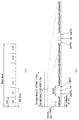
표 4는 기존 LCell UL에 적용되는 UL 그랜트 DCI(예, DCI 포맷 0)의 예이다. Table 4 is an example of UL Grant DCI (eg DCI Format 0) applied to existing LCell UL.
![]()
![]()
플래그 필드는 포맷 0과 포맷 1A의 구별을 위한 정보 필드이다. 즉, DCI 포맷 0과 1A는 동일한 페이로드 사이즈를 가지며 플래그 필드에 의해 구분된다. 자원블록 할당 및 홉핑 자원 할당 필드는 홉핑 PUSCH 또는 논-홉핑(non-hoppping) PUSCH에 따라 필드의 비트 크기가 달라질 수 있다. 논-홉핑 PUSCH를 위한 자원블록 할당 및 홉핑 자원 할당 필드는 ![]()
![]()
편의상, 먼저 UL 데이터 전송을 위한 DCI 컨텐츠를 아래와 같이 정의한다.For convenience, the DCI contents for UL data transmission are defined as follows.
1) RA(Resource Allocation): 데이터(예, UL-SCH 전송블록) 전송에 사용되는 자원(예, RB) 할당 정보(예, N 비트)1) RA (Resource Allocation): Resource (e.g., RB) allocation information (e.g., N bits) used for data (e.g., UL-
2) MCS: 데이터 전송에 사용되는 변조/부호 방식(예, 5 비트)2) MCS: modulation / coding scheme used for data transmission (eg, 5 bits)
3) DMRS CS: UL 데이터 채널(예, PUSCH)의 DMRS를 위한 CS 및 OCC(orthogonal cover code) 정보(예, 3 비트)3) DMRS CS: CS and orthogonal cover code (OCC) information (e.g., 3 bits) for the DMRS of the UL data channel (e.g., PUSCH)
4) TPC: UL 데이터 채널(예, PUSCH) 전송에 부가되는 전력 정보(예, 2 비트)4) TPC: Power information (e.g., 2 bits) added to the UL data channel (e.g., PUSCH)
5) CSI(Channel State Information) 요청(request): 비주기적 CSI 피드백 전송 여부를 지시(예, 1~3 비트)5) CSI (Channel State Information) request: Indicate whether aperiodic CSI feedback is transmitted (eg, 1 to 3 bits)
6) SRS 요청: 비주기적 SRS 신호 전송 여부를 지시(예, 1 비트)6) SRS Request: Indicate whether to transmit aperiodic SRS signal (
7) NDI: 새로운 데이터의 전송인지 이전 수신된 데이터에 대한 재전송인지의 여부를 지시(예, 1 비트)7) NDI: Indicates whether new data is transmitted or retransmitted for previously received data (eg, 1 bit)
8) HARQ ID: 데이터 전송에 대응되는 HARQ 프로세스 ID/번호(예, 3~4 비트)8) HARQ ID: HARQ process ID / number (e.g., 3 to 4 bits) corresponding to data transmission;
9) RV: 데이터 전송에 사용되는 리던던시 버전 정보(예, 2 비트)9) RV: Redundancy version information used for data transmission (eg, 2 bits)
10) DAI(Downlink Assignment Index): 단일 UL SF에 링크된 복수 DL SF(편의상, 번들링 윈도우)을 통해 스케줄링된 총 PDSCH (혹은, PDCCH) 개수를 지시(예, 2 비트)10) Downlink Assignment Index (DAI): Indicates the total number of PDSCHs (or PDCCHs) scheduled through multiple DL SFs (conveniently bundled windows) linked to a single UL SF,
이하의 설명에서 multi-SF는 문맥에 따라 multi-SF 스케줄링이 수행될 수 있는 최대 서브프레임 구간을 의미하거나, multi-SF 스케줄링이 수행되는 최대 서브프레임 구간 내에서 실제로 multi-SF 스케줄링이 적용되는 서브프레임 구간을 의미할 수 있다. 특별히 구별하지 않는 한, multi-SF는 실제로 multi-SF 스케줄링이 적용되는 서브프레임 구간을 의미할 수 있다. multi-SF는 연속된 SF일 수 있다.In the following description, multi-SF means a maximum sub-frame period in which multi-SF scheduling can be performed according to the context, or a sub-frame in which multi-SF scheduling is applied within the maximum sub- May refer to a frame period. Unless specifically distinguished, multi-SF may actually refer to a sub-frame period to which multi-SF scheduling is applied. A multi-SF can be a sequential SF.
(1) Method 1(1)
multi-SF 스케줄링 (UL 그랜트) DCI 설계를 위하여, DCI 컨텐츠를 3가지 컨텐츠 타입으로 분류할 수 있다. 또한, multi-SF 그랜트 DCI 내에 해당 DCI에 따른 스케줄링이 적용되는 SF 개수/구간을 지시하는 정보(이하, Nsf)를 추가로 시그널링 할 수 있다.Multi-SF Scheduling (UL Grant) For DCI design, DCI content can be classified into three types of content. In addition, information (hereinafter referred to as Nsf) indicating the SF number / interval to which the scheduling according to the DCI is applied in the multi-SF grant DCI can be additionally signaled.
1) 컨텐츠 타입 1: multi-SF에 공통적으로 (동일하게) 적용되는 정보1) Content type 1: Information applied in common (same) to multi-SF
A. multi-SF 그랜트 DCI 내에 하나의 값만 시그널링 되며, 해당 하나의 값이 multi-SF 전체에 모두 동일하게 적용됨A. Only one value is signaled in the multi-SF grant DCI, and one value is applied to all multi-SFs equally
B. 예, RA(N 비트), MCS(5 비트), DMRS CS(3 비트), TPC(2 비트) 등B. Yes, RA (N bits), MCS (5 bits), DMRS CS (3 bits), TPC (2 bits), etc.
2) 컨텐츠 타입 2: multi-SF에 속한 특정 SF 하나에만 (한번) 적용되는 정보2) Content type 2: information applied to only one specific SF belonging to multi-SF (once)
A. multi-SF 그랜트 DCI 내에 하나의 값만 시그널링 되며, 해당 값은 multi-SF에 속한 특정 SF 하나에만 적용됨A. Only one value is signaled in the multi-SF grant DCI, and the value applies only to one specific SF belonging to multi-SF.
B. 예, CSI 요청(2 비트), SRS 요청(1 비트), DAI(2 비트) 등B. Yes, CSI request (2 bits), SRS request (1 bit), DAI (2 bits), etc.
CSI/SRS는 특정 SF 하나에서만 전송되는 경우, 해당 SF에서 CCA가 실패하게 되면 단말은 CSI/SRS 전송 기회를 잃게 된다. 따라서, multi-SF의 각각의 SF에서 CSI/SRS를 전송하는 방안도 고려할 수 있다. 그러나, multi-SF의 각각의 SF에서 CSI/SRS를 전송하는 경우, 복수의 SRS 전송이 필요 없음에도 불구하고, 단말은 multi-SF의 매 SF에서 SRS 전송 동작을 수행하므로 UL 자원이 낭비될 수 있다. 한편, CSI/SRS는 특정 SF에서만 전송되는 경우, 해당 SF에서 CCA 실패로 CSI/SRS 전송이 실패하더라도, 기지국은 단말에게 CSI/SRS 전송을 재요청 할 수 있으므로 multi-SF에 속한 특정 SF 하나에서만 CSI/SRS를 전송하는 것이 바람직하다.If the CSI / SRS is transmitted only in one SF, the UE will lose the CSI / SRS transmission opportunity if the CC fails in the SF. Therefore, it is also possible to consider transmitting CSI / SRS in each SF of the multi-SF. However, when CSI / SRS is transmitted in each SF of multi-SF, although the UE does not need to transmit a plurality of SRSs, the UE performs an SRS transmission operation in every SF of the multi-SF, have. On the other hand, if the CSI / SRS is transmitted only in the specific SF, the BS can request the CSI / SRS transmission again, even if the CSI / SRS transmission fails due to the CCA failure in the corresponding SF. It is preferable to transmit CSI / SRS.
3) 컨텐츠 타입 3: multi-SF에 속한 각각의 SF 개별적으로 적용되는 정보3) Content type 3: Information applicable to each SF belonging to multi-SF individually
A. multi-SF 그랜트 DCI 내에 스케줄링 대상 SF 개수만큼 시그널링 되며, multi-SF에 속한 각각의 SF에 개별적으로 적용됨A. Multi-SF Grant Signals as many as the number of SFs to be scheduled in the DCI, individually applied to each SF belonging to multi-SF.
B. 예, NDI(1 비트), RV(2 비트), HARQ 프로세스 ID(3 비트) 등B. Yes, NDI (1 bit), RV (2 bits), HARQ process ID (3 bits), etc.
한편, multi-SF 그랜트 DCI는 스케줄링 대상 SF 개수/구간(즉, Nsf 값)에 관계없이 동일한 하나의 사이즈를 가지도록 구성될 수 있다. 즉, multi-SF 그랜트 DCI는 모든 Nsf 값에 대해 동일한 사이즈를 가지도록 구성될 수 있다. 일 예로, 최소 Nsf 값(예, 1)이 적용될 때의 DCI 컨텐츠 구성을 기준으로 multi-SF 그랜트 DCI 사이즈가 설정될 수 있다. 이러한 조건 하에, (1) multi-SF 그랜트 DCI 내에서 컨텐츠 타입 3에 대응되는 필드의 개수/사이즈는 Nsf 값에 비례적으로 할당될 수 있으며(즉, Nsf 값이 커질수록 해당 필드 수/사이즈가 증가), (2) multi-SF 그랜트 DCI 내에서 컨텐츠 타입 1/2에 대응되는 필드의 사이즈는 Nsf 값이 커질수록 감소되거나 해당 필드 자체가 생략될 수 있다. 다시 말해, (고정된 사이즈를 가지는 multi-SF 그랜트 DCI 내에서) Nsf 값이 커질수록 컨텐츠 타입 3(예, NDI, RV, HARQ ID)에 대응되는 필드의 개수/사이즈는 증가하는 반면, 컨텐츠 타입 1/2(예, RA, MCS, DMRS CS, TPC, CSI 요청, SRS 요청)에 대응되는 필드의 사이즈는 감소되거나 해당 필드가 생략될 수 있다. 이를 기반으로, Nsf 값에 따라 컨텐츠 타입 1/2 값의 그래뉼리티(granulity)(정보 단위의 크기)/가짓수 및/또는 대응되는 필드의 유무가 달라질 수 있다(Approach 1).Meanwhile, the multi-SF grant DCI may be configured to have the same size regardless of the number / period of SFs to be scheduled (i.e., Nsf value). That is, the multi-SF grant DCI can be configured to have the same size for all Nsf values. As an example, a multi-SF grant DCI size may be set based on the DCI content configuration when a minimum Nsf value (e.g., 1) is applied. Under this condition, (1) the number / size of the field corresponding to the
상기 과정의 일 예로, CSI 요청과 HARQ ID의 필드 사이즈를 각각 2 비트와 3 비트로 가정하고, Nsf = 1일 때를 기준으로 multi-SF 그랜트 DCI 사이즈를 (N + 19) 비트로 설정한 상황을 고려할 수 있다. 이 경우, 컨텐츠 타입 3은 NDI(1) + RV(2) + HARQ ID(3) = 6 비트가 할당될 수 있다. 괄호 안 숫자는 비트 수를 의미한다. 이러한 상황에서, Nsf = 2인 경우에는 컨텐츠 타입 3은 NDI(2) + RV(4) + HARQ ID(5 = ceiling(log2(8C2))) = 11 비트가 할당될 수 있다. 여기서, HARQ ID 필드에는 총 N = 8개의 HARQ ID들 중 Nsf = 2개를 선택하는 가짓수를 표현할 수 있는 최소 비트 수가 할당될 수 있다. Nsf = 2일 때의 컨텐츠 타입 3 필드 사이즈는 Nsf = 1일 때보다 5 비트 증가하므로, Nsf = 1일 때의 컨텐츠 타입 1/2 = RA(N) + MCS(5) + DMRS CS(3) + TPC(2) + CSI 요청(2) + SRS 요청(1) = (N + 13) 비트에서 5 비트를 뺀 (N + 8) 비트를 Nsf = 2일 때의 컨텐츠 타입 1/2 필드 사이즈로 할당할 수 있다. 예를 들면, RA(N - 2) + MCS(5 - 1) + DMRS CS(3 - 1) + TPC(2) + CSI 요청(2 - 1) + SRS 요청(1) = (N + 8) 비트로 Nsf = 2일 때의 컨텐츠 타입 1/2 필드를 구성할 수 있다. 이 경우, RA의 그래뉼리티가 커지거나(coarse)(예, RB 그룹의 사이즈가 커짐), MCS 및 DMRS CS 값의 가짓수가 줄어들 수 있다. CSI 요청의 경우 CSI 피드백 요청 대상으로 지시 가능한 DL 셀 조합 수가 감소할 수 있다.As an example of the above process, it is assumed that the field sizes of the CSI request and the HARQ ID are 2 bits and 3 bits, respectively, and a multi-SF grant DCI size is set to (N + 19) bits based on the case of Nsf = 1 . In this case, NDI (1) + RV (2) + HARQ ID (3) = 6 bits can be allocated for the
추가적으로, 위와 동일한 상황에서 Nsf = 4인 경우에 컨텐츠 타입 3은 NDI(4) + RV(8) + HARQ ID(7 = ceiling(log2(8C4))) = 19 비트가 할당될 수 있다. Nsf = 4일 때의 컨텐츠 타입 3 필드 사이즈는 Nsf = 1일 때보다 13 비트가 증가하므로 Nsf = 1일 때의 컨텐츠 타입 1/2 필드 사이즈 (N + 13) 비트에서 13 비트를 뺀 N 비트를 Nsf = 4일 때의 컨텐츠 타입 1/2 필드 사이즈로 할당할 수 있다. 예를 들면, RA(N - 6) + MCS(5 - 2) + DMRS CS(3 - 2) + TPC(2) + CSI 요청(2 - 2) + SRS 요청(1 - 1) = N 비트로 Nsf = 2일 때의 컨텐츠 타입 1/2 필드를 구성할 수 있다. 이 경우, RA의 그래뉼리티가 (Nsf = 2인 경우보다 더) 커지거나, MCS 및 DMRS CS 값의 가짓수가 (Nsf = 2인 경우보다 더) 줄어들 수 있다. 또한, CSI 요청 및 SRS 요청의 경우에는 필드가 생략되므로 Nsf = 4인 multi-SF 그랜트 DCI를 통해서는 비주기적 CSI/SRS 전송 요청이 허용되지 않을 수 있다.Additionally, in case of Nsf = 4 in the same situation as above, the
위와 다른 방법으로, 최대 Nsf 값 (Nsf_max)(예, 4 또는 8)이 적용될 때의 DCI 컨텐츠 구성을 기준으로 multi-SF 그랜트 DCI 사이즈를 설정하고, (최대 값보다 작은) 다른 Nsf 값이 적용될 경우에는 multi-SF 그랜트 DCI 내에 DCI 컨텐츠를 구성하고 남은 나머지 부분을 특정 비트(예, 0)로 패딩하는 방식으로 DCI 사이즈를 모든 Nsf 값에 대해 동일하게 설정할 수 있다(Approach 2). 즉, DCI 사이즈는 Nsf_max에 맞춰 구성되며, (Nsf_max보다 작은) 다른 Nsf 값이 적용되면 DCI 내에서 Nsf 값에 대응하는 정보만 사용된다. multi-SF가 연속된 SF인 경우를 고려하면, Nsf_max에 맞춰 multi-SF 그랜트 DCI 사이즈를 설정하는 것을 자원의 낭비일 수 있으나, Nsf 값에 관계없이 각 DCI 컨텐츠의 사이즈를 일정하게 유지함으로써 기지국과 단말간에 DCI 컨텐츠의 사이즈의 불일치를 방지할 수 있다. 또한, Nsf 값에 관계없이 DCI 컨텐츠의 사이즈를 일정하게 유지할 경우, 상기 컨텐츠 타입 1/2 값의 그래뉼리티(granulity)(정보 단위의 크기)/가짓수 및/또는 대응되는 필드의 유무가 모든 가능한 Nsf 값에 대해 동일하게 유지되므로, Nsf 값에 따른 스케줄링 제약/비효율성을 방지할 수 있다. 앞과 동일한 상황을 가정하면, 예를 들어 모든 Nsf 값에 대하여 컨텐츠 타입 1/2는 RA(N) + MCS(5) + DMRS CS(3) + TPC(2) + CSI 요청(2) + SRS 요청(1) = (N + 13) 비트가 동일하게 할당되고 최대 값인 Nsf = 4일 때의 컨텐츠 타입 3은 NDI(4) + RV(8) + HARQ ID(7 = ceiling(log2(8C4))) = 19 비트가 될 수 있다. 이를 기준으로 multi-SF 그랜트 DCI 사이즈는 (N + 32 = N + 13 + 19) 비트로 설정될 수 있다. 이러한 상황에서, Nsf = 2인 경우에는 컨텐츠 타입 3 필드 사이즈는 Nsf = 4일 때보다 8 비트가 감소한 11 비트로 할당될 수 있고, multi-SF 그랜트 DCI 내 해당 8 비트는 제로로 패딩될 수 있다. 즉, DCI 사이즈는 Nsf_max일 때의 컨텐츠 타입 3 필드의 사이즈에 기반하여 결정되며, (Nsf_max보다 작은) 다른 Nsf 값이 적용될 경우에는 DCI 내에서 Nsf에 대응하는 사이즈의 컨텐츠 타입 3 정보가 사용된다. 또한, Nsf = 1인 경우의 컨텐츠 타입 3 필드 사이즈는 Nsf = 4일 때보다 13 비트가 감소한 6 비트로 할당될 수 있고, multi-SF 그랜트 DCI 내 해당 13 비트는 제로로 패딩될 수 있다.Alternatively, if a multi-SF grant DCI size is set based on the DCI content configuration when the maximum Nsf value (Nsf_max) (e.g., 4 or 8) is applied and another Nsf value (smaller than the maximum value) is applied The DCI size can be set to the same value for all Nsf values (Approach 2) by configuring the DCI content in the multi-SF grant DCI and padding the remaining portion with a specific bit (e.g., 0). That is, the DCI size is configured for Nsf_max, and if another Nsf value (smaller than Nsf_max) is applied, only the information corresponding to the Nsf value in the DCI is used. Considering the case where multi-SFs are consecutive SFs, setting a multi-SF grant DCI size according to Nsf_max may be a waste of resources. However, by keeping the size of each DCI content constant regardless of the Nsf value, It is possible to prevent discrepancy in size of DCI contents between terminals. When the size of the DCI contents is kept constant regardless of the value of Nsf, granulity (size of information unit) / number of contents of the
Approach 2의 다른 방법으로, 최대 Nsf 값을 기준으로 DCI 사이즈를 설정하고, 최대 Nsf 값에 대응되는 DCI 컨텐츠를 구성한 상태에서(예, Nsf개 SF 각각에 개별적으로 컨텐츠 타입 3에 대응되는 정보 필드가 구성되어 총 Nsf개의 컨텐츠 타입 3 정보 필드가 구성됨), 컨텐츠 타입 3 정보를 복수의 SF에 대해 동일하게 설정할 수 있다. 이를 통해, Nsf를 묵시적(implicit)으로 알려줌으로써, multi-SF 그랜트 DCI 내에 Nsf를 별도로 시그널링 하지 않고도, 최대 값보다 작은 Nsf 값에 대응되는 multi-SF 스케줄링을 적용할 수 있다. 즉, 단말은 컨텐츠 타입 3 정보가 동일하게 설정된 SF의 개수에 기반하여 multi-SF 스케줄링이 적용될 SF 개수/구간으로 결정할 수 있다.In another approach of
일 예로, N(>1)개의 SF에 대해 컨텐츠 타입 3 정보의 전체 혹은 특정 일부(예, 적어도 HARQ ID를 포함)가 동일하게 설정된 경우, 해당 N개 SF들 중 특정 하나의 (예, 최초) SF에 대해서만 해당 컨텐츠 타입 3 정보에 기반한 PUSCH 전송을 수행하고, 나머지 (N - 1)개 SF에 대해서는 PUSCH 전송을 생략할 수 있다. 추가적인 예로, N개의 SF에 대해 NDI가 상이한 값으로 설정되고 해당 NDI를 제외한 나머지 컨텐츠 타입 3 정보의 전체 혹은 특정 일부(예, 적어도 HARQ ID를 포함)에 대해서는 동일한 값이 설정된 경우, 해당 N개 SF들 중 특정 하나의 (예, 최초) SF에 대해서만 해당 컨텐츠 타입 3 정보에 기반한 PUSCH 전송을 수행하고, 나머지 (N - 1)개 SF에 대해서는 PUSCH 전송을 생략할 수 있다.For example, when all or a specific part of the
다른 예로, MCS가 컨텐츠 타입 3로 설정/구성되는 경우에는, 특정 MCS 값 혹은 특정 MCS 값과 특정 RV 값의 조합에 대응되는 SF를 통해서는 PUSCH 전송을 생략할 수 있다. 추가적인 예로, MCS와 RA가 모두 컨텐츠 타입 3로 설정/구성되는 경우에는, 특정 MCS 값과 특정 RA(예, 특정 RB(G) 개수 및/또는 특정 RB(G) 인덱스)의 조합 혹은 특정 MCS 값과 특정 RA와 특정 RV 값의 조합에 대응되는 SF를 통해서는 PUSCH 전송을 생략할 수 있다.As another example, when the MCS is set / configured as the
또 다른 방법으로, 특정 Nsf 값이 적용될 때의 DCI 컨텐츠 구성을 기준으로 multi-SF 그랜트 DCI 사이즈를 설정하고, Nsf 값이 특정 Nsf 값보다 큰 경우에는 Approach 1을 적용하고, Nsf 값이 특정 Nsf 값보다 작은 경우에는 Approach 2를 적용할 수 있다(Approach 3). 또 다른 방법으로, (Approach 1을 통한) DCI 감소(reduction) 혹은 (Approach 2를 통한) 비트 패딩없이 각 Nsf 값 별로 (상이한 사이즈를 가지는) multi-SF 그랜트 DCI를 구성한 상태에서, multi-SF 그랜트 DCI에 대한 BD(blind decoding)을 위한 (E)PDCCH SS(search space)를 Nsf 값 별로 다르게 할당할 수 있다. 이 경우, Nsf 값에 대한 별도의 DCI 시그널링 없이 단말은 multi-SF 그랜트 DCI가 검출된 SS 자원/영역에 링크/설정된 Nsf 값을 해당 DCI 기반의 multi-SF 스케줄링이 적용될 SF 개수/구간으로 결정할 수 있다. 또 다른 방법으로, 전체 Nsf 값들을 복수의 세트로 나누고 각 Nsf 값 세트 별로 Approach 1/2/3를 적용하여 (상이한 사이즈를 가지는) multi-SF 그랜트 DCI를 구성한 상태에서, multi-SF 그랜트 DCI의 BD를 위한 SS를 Nsf 값 세트 별로 다르게 할당할 수 있다. 일 예로, Nsf = 1에 해당하는 기존 single-SF 그랜트 DCI와 (이와 상이한 사이즈를 가지는) Nsf > 1에 해당하는 (Approach 1/2/3를 적용한) multi-SF 그랜트 DCI를 구성한 상태에서, single-SF 그랜트 DCI와 multi-SF 그랜트 DCI의 BD를 위한 SS를 서로 다르게 할당할 수 있다.In another method, a multi-SF grant DCI size is set based on the DCI contents configuration when a specific Nsf value is applied. When the Nsf value is larger than a specific Nsf value,
추가적으로, 서로 다른 단말의 PUSCH 전송간 TDM 및 하나의 단말의 (상이한 RB 및/또는 MCS 및/또는 TBS(Transport Block Size) 기반의) PUSCH 전송간 TDM 등을 지원하기 위하여, (i) multi-SF 스케줄링이 적용될 최초 SF, 혹은 (ii) 스케줄링 대상 multi-SF에 속한 최초 SF (즉, multi-SF 내에서 스케줄링이 적용될 최초 SF)에 대한 정보가 multi-SF 그랜트 DCI를 통해 시그널링 될 수 있다(이하, (i)~(ii)를 first-SF로 통칭). 또는, (first-SF에 대한 별도의 DCI 시그널링 없이) 사전에 지정된 각 first-SF별로 multi-SF 그랜트 DCI를 구성한 상태에서, multi-SF 그랜트 DCI에 대한 BD를 위한 SS를 first-SF별로 다르게 할당할 수 있다. 즉, 단말은 DCI가 검출된 SS 자원/영역에 링크/설정된 first-SF를 해당 DCI 기반의 스케줄링이 적용될 multi-SF의 최초 SF로 결정할 수 있다. 또한, 서로 다른 first-SF에 대응되는 복수의 multi-SF 그랜트 DCI가 하나의 DL SF를 통해 동시 전송/검출 가능하도록 설정될 수 있다.Additionally, in order to support TUS between PUSCH transmissions of different UEs and TUS between PUSCH transmissions (based on different RBs and / or MCS and / or TBS (Transport Block Size)) of one UE, Information about the first SF to which the scheduling is to be applied, or (ii) the first SF belonging to the multi-SF to be scheduled (i.e., the first SF to be scheduled in the multi-SF) may be signaled through the multi-SF grant DCI , (i) to (ii) are referred to as first-SF). Alternatively, in a multi-SF grant DCI configured for each previously-specified first SF (without separate DCI signaling for first-SF), SS for BD for multi-SF grant DCI is allocated differently for first SF can do. That is, the UE can determine the first SF that is linked / set to the SS resource / region in which the DCI is detected as the first SF of the multi-SF to which the corresponding DCI based scheduling is applied. Further, a plurality of multi-SF grant DCIs corresponding to different first-SFs can be set to be simultaneously transmitted / detected through one DL SF.
한편, RA를 컨텐츠 타입 3으로 고려할 경우, DCI 내 RA 필드 (사이즈)는 시스템 BW(bandwidth)를 Nsf 값만큼 확장한 크기의 BW에 대한 자원 할당 정보를 포함하는 형태로 구성/할당될 수 있다. 일 예로, 시스템 BW가 N의 RB이고 Nsf = K인 경우 총 K*N개 RB에 해당하는 확장된 BW에 대한 자원 할당 정보를 포함하는 RA 필드 (사이즈)가 multi-SF 그랜트 DCI 내에 구성/할당될 수 있다. 구체적인 일례로, 해당 RA 필드상에서 (k-1)*N+1번째 RB부터 k*N번째 RB까지의 RB 구간 내에 할당된 자원이, 스케줄링된 multi-SF 내의 k번째 SF에 할당되는 PUSCH 자원으로 결정될 수 있다. 이렇게 함으로써, N개 RB에 해당하는 BW에 대한 자원 할당 정보를 포함하는 RA 필드 (사이즈)가 K개 구성/할당되는 경우에 비해 RA 필드 사이즈를 줄일 수 있다. 또한, MCS를 컨텐츠 타입 3으로 고려할 경우 (전체 multi-SF 내에서) first-SF에만 원래 그래뉼리티의 MCS 인덱스를 할당하고 나머지 SF에 대해서는 first-SF에 할당된 MCS 정보에 인덱스 오프셋을 적용하는 형태로 DCI 내 필드 (사이즈)가 구성/할당될 수 있다. 일 예로, 원래 MCS가 N 비트로 구성되고 Nsf = K인 경우, first-SF 하나에만 N-비트 MCS 인덱스가 할당되고 나머지 (K - 1)개 SF에 대해서는 L-비트 인덱스 오프셋 (L < N)가 할당되는 형태로 MCS 필드 (사이즈)가 multi-SF 그랜트 DCI 내에 구성/할당될 수 있다. 나머지 (K - 1)개 SF에 대해 적용되는 MCS 인덱스는 해당 N-비트 MCS 인덱스에 L-비트 인덱스 오프셋 (L < N)을 적용함으로써 얻어질 수 있다.On the other hand, when the RA is considered as the
또 다른 방안으로, multi-SF 스케줄링 방식을 통해서는 (이전 수신된 데이터에 대한 재전송이 아닌) 새로운 데이터의 전송에 대한 스케줄링만을 수행하는 방안을 고려할 수 있다. 재전송은 기존 single-SF 스케줄링 방식을 통해 수행할 수 있다. 이 경우, multi-SF 그랜트 DCI에서 NDI는 SF별로 개별적인 구성/지시되는 반면, RV는 필드 구성 (이를 통한 시그널링) 자체가 생략될 수 있다. 이에 따라, multi-SF 그랜트 DCI 기반 스케줄링의 경우에는 사전에 설정된 특정 RV 값(예, 초기값 0)이 적용될 수 있다. 추가로, NDI를 컨텐츠 타입 1로 고려하여 multi-SF 전체에 동일한 하나의 NDI 값을 지시/적용하는 것도 가능하다.As another alternative, it is possible to consider scheduling only the transmission of new data (not the retransmission of the previously received data) through the multi-SF scheduling scheme. The retransmission can be performed through the existing single-SF scheduling scheme. In this case, in the multi-SF grant DCI, the NDI is separately configured / indicated for each SF, whereas the RV field configuration (signaling through it) itself may be omitted. Accordingly, in the case of the multi-SF grant DCI-based scheduling, a preset specific RV value (e.g., initial value 0) may be applied. In addition, it is also possible to indicate / apply the same NDI value to the entire multi-SF by considering the NDI as the
(2) Method 2(2)
Method 1은 스케줄링 대상 SF 개수/구간의 변동을 고려한 단일 사이즈의 multi-SF 그랜트 DCI 구성 방법을 제시하며, 상이한 SF 개수/구간 (즉, Nsf 값)에 대한 multi-SF 스케줄링 지원을 가능하게 한다. 그러나, Nsf 값에 따른 DCI 그래뉼리티 변동과 비트 패딩 처리 등으로 인하여 스케줄링 정확성/오버헤드 측면에서 다소 비효율적일 수 있다. 이에, DCI에 대한 BD를 늘리지 않으면서 스케줄링 정확성/오버헤드를 개선시킬 수 있는 부분(partial) DCI 전송 기반의 multi-SF 스케줄링 방법을 제안한다.
본 방법에서 multi-SF 스케줄링을 위한 multi-SF 그랜트 DCI는 기본적으로 2개의 부분 DCI로 구성된다. 각 부분 DCI에는 채널 부호화가 개별적으로 수행되고, 각 부분 DCI는 서로 다른 제어 채널 자원(예, (E)CCE)을 통해 전송될 수 있다. 구체적으로, 첫 번째 부분 DCI(이하, 부분 DCI-1)에는 Nsf 정보, 컨텐츠 타입 1/2, 및 first-SF 하나에 대한 컨텐츠 타입 3가 포함될 수 있고, 두 번째 부분 DCI(이하, 부분 DCI-2)에는 (multi-SF 내에서) first-SF를 제외한 나머지 SF들에 대한 컨텐츠 타입 3이 포함될 수 있다. 두 개의 부분 DCI의 페이로드 사이즈는 상이하게 설정될 수 있다. 예를 들어, 부분 DCI-1는 고정된 페이로드 사이즈를 가지는 반면, 부분 DCI-2는 Nsf 값에 따라 페이로드 사이즈가 달라질 수 있다.In this method, a multi-SF grant DCI for multi-SF scheduling is basically composed of two partial DCIs. In each partial DCI, channel coding is performed separately, and each partial DCI can be transmitted via different control channel resources (e.g., (E) CCE). Specifically, the first partial DCI (hereinafter referred to as partial DCI-1) may include
한편, 각각의 부분 DCI에 대해서는 CRC가 개별적으로 생성/추가될 수 있다. 일 예로, 부분 DCI-1의 CRC에는 기존처럼 C-RNTI 기반의 스크램블링/마스킹이 적용되는 반면, 부분 DCI-2의 CRC에는 별도의 스크램블링/마스킹이 적용되지 않을 수 있다. 이 경우, 두 부분 DCI의 CRC 길이는 상이하게 설정될 수 있다(예, 부분 DCI-2의 CRC가 부분 DCI-1의 CRC보다 작은 길이를 가짐). 또한, 부분 DCI-2의 전송 자원에 대한 정보는 부분 DCI-1 검출을 통해 결정될 수 있다. 예를 들어, 부분 DCI-2이 전송되는 자원에 대한 정보는 부분 DCI-1을 통해 직접 시그널링 되거나, 부분 DCI-1의 전송 자원에 특정 오프셋이 추가된 형태로 결정될 수 있다. 부분 DCI-1의 전송 자원이 복수의 자원 유닛으로 구성된 경우, 부분 DCI-2의 전송 자원 정보는 DCI-1의 전송 자원을 구성하는 복수의 자원 유닛 중 특정(예, 첫 번째) 자원 유닛의 인덱스에 오프셋이 추가된 형태로 결정될 수 있다.On the other hand, for each partial DCI, CRCs can be individually generated / added. For example, C-RNTI-based scrambling / masking may be applied to the CRC of the partial DCI-1, whereas a separate scrambling / masking may not be applied to the CRC of the partial DCI-2. In this case, the CRC lengths of the two part DCIs may be set differently (e.g., the CRC of the partial DCI-2 has a length less than the CRC of the partial DCI-1). In addition, information about the transmission resources of the partial DCI-2 may be determined through partial DCI-1 detection. For example, information about the resource to which the partial DCI-2 is transmitted may be directly signaled through the partial DCI-1, or may be determined in the form of adding a specific offset to the transmission resource of the partial DCI-1. When the transmission resource of the partial DCI-1 is composed of a plurality of resource units, the transmission resource information of the partial DCI-2 is an index of a specific (e.g., first) resource unit among a plurality of resource units constituting transmission resources of the DCI- May be determined in a form in which an offset is added.
본 방법에 따라, 단말은 우선 BD를 통해 부분 DCI-1의 검출을 시도할 수 있으며, 부분 DCI-1 내의 정보(예, Nsf) 및/또는 부분 DCI-1 전송에 사용된 자원 등을 토대로 (부분 DCI-2의 페이로드 사이즈 및/또는 전송 자원을 결정하여) 부분 DCI-2에 대한 검출/복호를 시도할 수 있다. 부분 DCI-1과 이에 대응되는 부분 DCI-2를 모두 검출한 경우, 단말은 부분 DCI-1/2의 정보를 결합하여 multi-SF에 적용할 수 있다. 부분 DCI-1만 검출하고 부분 DCI-2 검출에는 실패한 경우, 단말은 1) 부분 DCI-1을 first-SF에만 적용하거나, 2) 부분 DCI-1을 무시하도록 동작할 수 있다. 한편, Nsf = 1인 경우에는 부분 DCI-2에 대한 전송/검출이 생략될 수 있으며, 부분 DCI-1을 first-SF에 적용하도록 동작할 수 있다.According to the present method, the terminal may first attempt to detect the partial DCI-1 via the BD, and based on the information (e.g. Nsf) in the partial DCI-1 and / or resources used in the partial DCI- (E.g., determining the payload size and / or transmission resources of the partial DCI-2) to detect / decode the partial DCI-2. If both the partial DCI-1 and the corresponding partial DCI-2 are detected, the UE can combine the partial DCI-1/2 information and apply it to the multi-SF. If only partial DCI-1 is detected and partial DCI-2 detection fails, the terminal may operate to 1) apply partial DCI-1 only to first-SF, or 2) ignore partial DCI-1. On the other hand, if Nsf = 1, transmission / detection for the partial DCI-2 may be omitted and the partial DCI-1 may be operated to apply to the first-SF.
도 14는 본 발명에 따른 UL 전송 과정을 예시한다.14 illustrates a UL transmission process according to the present invention.
도 14를 참조하면, 단말은 복수 서브프레임에 대한 UL 스케줄링 정보를 포함하는 DCI(즉, multi-SF 그랜트 DCI)를 기지국으로부터 수신할 수 있다(S1402). multi-SF 그랜트 DCI는 Method 1 또는 2에 기반하여 구성될 수 있다. 이후, 단말은 UL 스케줄링 정보에 따라 복수 서브프레임에서 복수의 UL 채널(예, PUSCH)을 전송할 수 있다. 여기서, 복수 서브프레임은 multi-SF 스케줄링이 수행될 수 있는 최대 서브프레임 구간을 의미하거나, multi-SF 스케줄링이 수행되는 최대 서브프레임 구간 내에서 실제로 multi-SF 스케줄링이 적용되는 서브프레임 구간을 의미할 수 있다. 복수 서브프레임의 개수/구간을 지시하는 정보(즉, Nsf)는 multi-SF 그랜트 DCI 내에 포함될 수 있다. multi-SF 그랜트 DCI는 UCell 상의 복수 서브프레임에 대한 UL 스케줄링 정보를 포함할 수 있다. 또한, multi-SF 그랜트 DCI는 UCell 또는 LCell(예, PCell) 상에서 수신될 수 있다. 또한, 무선 통신 시스템은 LTE LAA-기반 무선 통신 시스템을 포함할 수 있다.Referring to FIG. 14, a UE may receive DCI (i.e., multi-SF grant DCI) including UL scheduling information for a plurality of subframes from a base station (S1402). The multi-SF grant DCI can be configured based on
(3) Other issues(3) Other issues
Method 1/2 혹은 다른 방식을 기반으로 multi-SF 스케줄링이 적용될 경우, multi-SF 그랜트 DCI 내의 (컨텐츠 타입 2에 해당될 수 있는) CSI 요청 및 SRS 요청에 대응되는 UL SF 시점(예, 비주기적 CSI 피드백을 포함한 PUSCH의 전송 시점, 혹은 비주기적 SRS 신호의 전송 시점)을 설정하는 것이 필요하다. multi-SF 그랜트 DCI 내의 CSI 요청 및/또는 SRS 요청에 대응되는 UL SF 시점은 1) first-SF(즉, UL 전송이 스케줄링된 첫 번째 SF), 2) multi-SF 내 (multi-SF 스케줄링이 적용되는) 마지막 SF(예, UL 전송이 스케줄링된 마지막 SF), 혹은 3) 최초로 CCA에 성공한 SF(즉, UCell 무선 채널이 빈(idle)다고 판단된 SF)로 설정될 수 있다. 3)의 경우, CCA 결과에 따라 SRS 전송 시점이 달라지므로, 이로 인해 단말간에 SRS 전송과 PUSCH 전송이 충돌할 가능성이 높아질 수 있다. 한편, 기지국이 multi-SF에서 UL SF 전송이 종료된 직후에 바로 이어서 DL SF 전송을 구성하려고 하는 경우에는 SRS 전송에 의해 기지국의 CCA가 실패할 수 있으므로 2)보다 1)이 바람직할 수 있다. When the multi-SF scheduling is applied based on
도 15는 본 발명에 따른 SRS 전송 과정을 예시한다.15 illustrates an SRS transmission process according to the present invention.
도 15를 참조하면, 단말은 복수 서브프레임에 대한 UL 스케줄링 정보를 포함하는 DCI(즉, multi-SF 그랜트 DCI)를 기지국으로부터 수신할 수 있다(S1502). multi-SF 그랜트 DCI는 SRS 요청 정보를 더 포함할 수 있다. multi-SF 그랜트 DCI는 Method 1 또는 2에 기반하여 구성될 수 있다. 이후, 단말은 SRS 요청 정보의 지시에 따라, 복수 서브프레임 내의 기-지정된 서브프레임을 통해 1회만 SRS를 전송할 수 있다(S1504). 여기서, 기-지정된 서브프레임은 복수 서브프레임 내에서 UL 전송이 스케줄링된 첫 번째 서브프레임 또는 UL 전송이 스케줄링된 마지막 서브프레임을 포함할 수 있다. 여기서, 복수 서브프레임은 multi-SF 스케줄링이 수행될 수 있는 최대 서브프레임 구간을 의미하거나, multi-SF 스케줄링이 수행되는 최대 서브프레임 구간 내에서 실제로 multi-SF 스케줄링이 적용되는 서브프레임 구간을 의미할 수 있다. 복수 서브프레임의 개수/구간을 지시하는 정보(즉, Nsf)는 multi-SF 그랜트 DCI 내에 포함될 수 있다. 한편, 단말은 multi-SF 그랜트 DCI 내의 UL 스케줄링 정보에 기반하여, 복수 서브프레임에서 복수의 UL 전송(예, PUSCH 전송)을 수행할 수 있다. 또한, multi-SF 그랜트 DCI는 UCell 상의 복수 서브프레임에 대한 UL 스케줄링 정보를 포함하고, SRS는 UCell 상에서 전송될 수 있다. 또한, multi-SF 그랜트 DCI는 UCell 또는 LCell(예, PCell) 상에서 수신될 수 있다. 또한, 무선 통신 시스템은 LTE LAA-기반 무선 통신 시스템을 포함할 수 있다.Referring to FIG. 15, a UE may receive DCI (i.e., multi-SF grant DCI) including UL scheduling information for a plurality of subframes from a base station (S1502). The multi-SF grant DCI may further include SRS request information. The multi-SF grant DCI can be configured based on
또한, multi-SF 그랜트 DCI 내의 (컨텐츠 타입 2에 해당될 수 있는) DAI 값이 적용되는 (예, 해당 DAI 값을 기반으로 PUSCH를 통해 전송되는 HARQ-ACK 페이로드 사이즈가 결정되는) UL SF 시점은, 1) first-SF만으로 설정되거나, 2) multi-SF 내에서 최초로 HARQ-ACK 전송이 수행되는 SF만으로 설정될 수 있다. multi-SF 내 나머지 UL SF에서의 PUSCH를 통해 전송되는 HARQ-ACK 페이로드 사이즈는 최대 사이즈(예, 해당 UL SF에 링크된 번들링 윈도우 내의 총 DL SF 수)로 결정될 수 있다. 또 다른 방법으로, DCI 오버헤드를 줄이기 위하여 multi-SF 그랜트 DCI 내에 DAI 필드 구성 및 이를 통한 DAI 시그널링을 생략할 수 있다. 이에 따라, multi-SF 그랜트 DCI를 통해 스케줄링된 모든 UL SF에서의 PUSCH를 통해 전송되는 HARQ-ACK 페이로드 사이즈는 항상 최대 사이즈로 결정될 수 있다.Also, the UL SF point (for which the HARQ-ACK payload size transmitted through the PUSCH is determined based on the corresponding DAI value) to which the DAI value (corresponding to the content type 2) in the multi-SF grant DCI is applied May be set to 1) only the first SF, or 2) only the SF in which the HARQ-ACK transmission is first performed in the multi-SF. The HARQ-ACK payload size transmitted on the PUSCH in the remaining UL SF in the multi-SF may be determined to be the maximum size (e.g., the total number of DL SFs in the bundling window linked to the corresponding UL SF). Alternatively, the DAI field configuration and DAI signaling through the multi-SF grant DCI may be omitted in order to reduce the DCI overhead. Accordingly, the HARQ-ACK payload size transmitted through the PUSCH in all the UL SFs scheduled through the multi-SF grant DCI can always be determined as the maximum size.
한편, multi-SF 그랜트 DCI에 포함된 TPC에 대해서는 (수신된 TPC 커맨드에 대한) 누적(accumulation) 설정 여부에 따라, 1) 누적이 이네이블(enable)된 경우에는 해당 TPC를 first-SF에 한번만 적용하도록 동작할 수 있으며, 2) 누적이 디스에이블(disable)된 경우에는 해당 TPC를 스케줄링된 multi-SF에 속한 모든 SF에 매번 적용하도록 동작할 수 있다.On the other hand, depending on whether accumulation is set for the TPC included in the multi-SF grant DCI, 1) when accumulation is enabled, the corresponding TPC is updated only once in the first SF And 2) if accumulation is disabled, the TPC may be applied to all SFs belonging to the scheduled multi-SF every time.
(4) UCell scheduling(4) UCell scheduling
CCA를 기반으로 동작하는 UCell에 대한 UL PUSCH 스케줄링 (이를 위한 UL 그랜트 DCI 전송)을 해당 UCell에서 수행하는 self-CC 스케줄링 상황을 고려할 경우, 실제 PDSCH 스케줄링이 요구되지 않는 상황임에도 불구하고 기지국은 UL 그랜트 DCI 전송만을 위한 DL 구간을 (CCA를 기반으로) 구성/확보해야 할 수 있다. 하지만, 이로 인해, UCell 상의 유연하고 효율적인 DL/UL 자원 구간(예, SF) 구성을 용이하지 않을 수 있으며, 전체적인 시스템 성능이 저하될 수 있다.Considering a self-CC scheduling situation in which UL PUSCH scheduling (UC Grant DCI transmission for UCell) based on the CCA is performed in the UCell, although the actual PDSCH scheduling is not required, It may be necessary to configure / secure the DL interval (based on CCA) only for DCI transmissions. However, this may make it difficult to construct a flexible and efficient DL / UL resource section (e.g., SF) on the UCell, and the overall system performance may be degraded.
이러한 문제를 감안하여, 하나의 UCell에 대한 DL 스케줄링 (이를 위한 DL 그랜트 전송)을 수행하는 셀 (즉, DL 스케줄링 셀)은 기존과 동일하게 하나의 셀로 설정하는 반면, UL 스케줄링 (이를 위한 UL 그랜트 전송)을 수행하는 셀(즉, UL 스케줄링 셀)은 복수의 셀로 설정하는 방안을 고려할 수 있다. 이에 따라, 단말은 UCell DL 스케줄링에 대해서는 하나의 시점에 하나의 DL 스케줄링 셀 상에서만 DL 그랜트 DCI 검출을 수행하는 반면, UCell UL 스케줄링에 대해서는 하나의 시점에 복수의 UL 스케줄링 셀 상에서 동시에 UL 그랜트 DCI 검출을 수행하도록 동작할 수 있다. 예를 들어, 하나의 UCell에 대하여 2개의 UL 스케줄링 셀이 설정될 수 있다. 이 경우, 2개의 UL 스케줄링 셀은 1) 스케줄링 대상인 해당 UCell과 하나의 LCell로 설정되거나, 2) 서로 다른 2개의 LCell로 설정될 수 있다.In consideration of this problem, a cell (DL scheduling cell) that performs DL scheduling for one UCell (DL grant transmission for this) is set to one cell in the same manner as the conventional one, while UL scheduling (I.e., a UL scheduling cell) to be transmitted to a plurality of cells may be considered. Accordingly, the UE performs DL Grant DCI detection on only one DL scheduling cell at one time for UCell DL scheduling, while UL Grant DCI detection is performed simultaneously on a plurality of UL scheduling cells at one time for UCell UL scheduling. Lt; / RTI > For example, two UL scheduling cells may be set for one UCell. In this case, the two UL scheduling cells may be set to 1) a corresponding UCell to be scheduled and one LCell, or 2) two different LCells.
위와 같은 설정 하에서, UL 그랜트 DCI 검출을 위한 또 다른 방법으로, 복수의 UL 스케줄링 셀 중 어느 셀 상에서 (스케줄링 대상) UCell에 대한 UL 그랜트 DCI 검출을 수행할지를, 해당 UCell (또는 PCell) 상으로 전송되는 특정 시그널링(예, 단말-공통 PDCCH)을 통해 단말에게 지시하는 방식을 고려할 수 있다. 이 경우, 단말은 특정 시그널링을 통해 지시된 UL 스케줄링 셀 상에서만 해당 UCell에 대한 UL 그랜트 DCI 검출을 수행하도록 동작할 수 있다. 단말이 특정 시그널링 검출에 실패한 경우에는, 1) 가장 최근 지시된 UL 스케줄링 셀 상에서 UL 그랜트 DCI 검출을 수행하거나, 2) 복수 UL 스케줄링 셀 중 (미리 지정된) 특정 LCell 상에서 UL 그랜트 DCI 검출을 수행하도록 동작할 수 있다.Under the above setting, as another method for detecting UL grant DCI, the UL Grant DCI detection for a UCell (scheduled to be scheduled) on a cell among a plurality of UL scheduling cells is carried out on the corresponding UCell (or PCell) And a method of instructing the UE through specific signaling (e.g., UE-common PDCCH). In this case, the terminal may be operable to perform UL Grant DCI detection on the UCell only on the UL scheduling cell indicated by the specific signaling. 1) perform UL Grant DCI detection on the most recently indicated UL scheduling cell, or 2) perform UL Grant DCI detection on a (predefined) specific LCell of a plurality of UL scheduling cells. If the UE fails to detect a specific signaling, can do.
추가적으로, (위와 반대로) 하나의 UCell에 대해 하나의 UL 스케줄링 셀과 복수(예, 2개)의 DL 스케줄링 셀을 설정하는 방식도 가능하다. 2개의 DL 스케줄링 셀을 고려할 경우, DL 스케줄링 셀은 1) 스케줄링 대상인 해당 UCell과 하나의 LCell로 설정되거나, 2) 서로 다른 2개의 LCell로 설정될 수 있다. 한편, 본 방법의 DL/UL 스케줄링 셀 설정 방식은 UCell에 대한 스케줄링에만 국한되지 않으며, LCell을 포함한 임의의 셀에 대한 스케줄링에도 일반적으로 적용될 수 있다.Additionally, it is possible to configure one UL scheduling cell and a plurality of (e.g., two) DL scheduling cells for one UCell (as opposed to). Considering two DL scheduling cells, the DL scheduling cell may be set to 1) a corresponding UCell to be scheduled and one LCell, or 2) two different LCells. On the other hand, the DL / UL scheduling cell setting method of the present method is not limited to the scheduling for the UCell, and can be generally applied to the scheduling for any cell including the LCell.
도 16은 본 발명에 적용될 수 있는 기지국 및 단말을 예시한다.16 illustrates a base station and a terminal that can be applied to the present invention.
도 16을 참조하면, 무선 통신 시스템은 기지국(BS, 110) 및 단말(UE, 120)을 포함한다. 무선 통신 시스템이 릴레이를 포함하는 경우, 기지국 또는 단말은 릴레이로 대체될 수 있다.Referring to FIG. 16, a wireless communication system includes a base station (BS) 110 and a terminal (UE) 120. If the wireless communication system includes a relay, the base station or the terminal may be replaced by a relay.
기지국(110)은 프로세서(112), 메모리(114) 및 무선 주파수(Radio Frequency: RF) 유닛(116)을 포함한다. 프로세서(112)는 본 발명에서 제안한 절차 및/또는 방법들을 구현하도록 구성될 수 있다. 메모리(114)는 프로세서(112)와 연결되고 프로세서(112)의 동작과 관련한 다양한 정보를 저장한다. RF 유닛(116)은 프로세서(112)와 연결되고 무선 신호를 송신 및/또는 수신한다. 단말(120)은 프로세서(122), 메모리(124) 및 무선 주파수 유닛(126)을 포함한다. 프로세서(122)는 본 발명에서 제안한 절차 및/또는 방법들을 구현하도록 구성될 수 있다. 메모리(124)는 프로세서(122)와 연결되고 프로세서(122)의 동작과 관련한 다양한 정보를 저장한다. RF 유닛(126)은 프로세서(122)와 연결되고 무선 신호를 송신 및/또는 수신한다.The
이상에서 설명된 실시예들은 본 발명의 구성요소들과 특징들이 소정 형태로 결합된 것들이다. 각 구성요소 또는 특징은 별도의 명시적 언급이 없는 한 선택적인 것으로 고려되어야 한다. 각 구성요소 또는 특징은 다른 구성요소나 특징과 결합되지 않은 형태로 실시될 수 있다. 또한, 일부 구성요소들 및/또는 특징들을 결합하여 본 발명의 실시예를 구성하는 것도 가능하다. 본 발명의 실시예들에서 설명되는 동작들의 순서는 변경될 수 있다. 어느 실시예의 일부 구성이나 특징은 다른 실시예에 포함될 수 있고, 또는 다른 실시예의 대응하는 구성 또는 특징과 교체될 수 있다. 특허청구범위에서 명시적인 인용 관계가 있지 않은 청구항들을 결합하여 실시예를 구성하거나 출원 후의 보정에 의해 새로운 청구항으로 포함시킬 수 있음은 자명하다.The embodiments described above are those in which the elements and features of the present invention are combined in a predetermined form. Each component or feature shall be considered optional unless otherwise expressly stated. Each component or feature may be implemented in a form that is not combined with other components or features. It is also possible to construct embodiments of the present invention by combining some of the elements and / or features. The order of the operations described in the embodiments of the present invention may be changed. Some configurations or features of certain embodiments may be included in other embodiments, or may be replaced with corresponding configurations or features of other embodiments. It is clear that the claims that are not expressly cited in the claims may be combined to form an embodiment or be included in a new claim by an amendment after the application.
본 문서에서 본 발명의 실시예들은 주로 단말과 기지국 간의 신호 송수신 관계를 중심으로 설명되었다. 이러한 송수신 관계는 단말과 릴레이 또는 기지국과 릴레이간의 신호 송수신에도 동일/유사하게 확장된다. 본 문서에서 기지국에 의해 수행된다고 설명된 특정 동작은 경우에 따라서는 그 상위 노드(upper node)에 의해 수행될 수 있다. 즉, 기지국을 포함하는 복수의 네트워크 노드들(network nodes)로 이루어지는 네트워크에서 단말과의 통신을 위해 수행되는 다양한 동작들은 기지국 또는 기지국 이외의 다른 네트워크 노드들에 의해 수행될 수 있음은 자명하다. 기지국은 고정국(fixed station), Node B, eNode B(eNB), 억세스 포인트(access point) 등의 용어에 의해 대체될 수 있다. 또한, 단말은 UE(User Equipment), MS(Mobile Station), MSS(Mobile Subscriber Station) 등의 용어로 대체될 수 있다.In the present document, the embodiments of the present invention have been mainly described with reference to a signal transmission / reception relationship between a terminal and a base station. This transmission / reception relationship is equally or similarly extended to the signal transmission / reception between the terminal and the relay or between the base station and the relay. The specific operation described herein as being performed by the base station may be performed by its upper node, in some cases. That is, it is apparent that various operations performed for communication with a terminal in a network including a plurality of network nodes including a base station can be performed by a network node other than the base station or the base station. A base station may be replaced by terms such as a fixed station, a Node B, an eNode B (eNB), an access point, and the like. In addition, the terminal may be replaced by terms such as a UE (User Equipment), a Mobile Station (MS), and a Mobile Subscriber Station (MSS).
본 발명에 따른 실시예는 다양한 수단, 예를 들어, 하드웨어, 펌웨어(firmware), 소프트웨어 또는 그것들의 결합 등에 의해 구현될 수 있다. 하드웨어에 의한 구현의 경우, 본 발명의 일 실시예는 하나 또는 그 이상의 ASICs(application specific integrated circuits), DSPs(digital signal processors), DSPDs(digital signal processing devices), PLDs(programmable logic devices), FPGAs(field programmable gate arrays), 프로세서, 콘트롤러, 마이크로 콘트롤러, 마이크로 프로세서 등에 의해 구현될 수 있다.Embodiments in accordance with the present invention may be implemented by various means, for example, hardware, firmware, software, or a combination thereof. In the case of hardware implementation, an embodiment of the present invention may include one or more application specific integrated circuits (ASICs), digital signal processors (DSPs), digital signal processing devices (DSPDs), programmable logic devices (PLDs) field programmable gate arrays, processors, controllers, microcontrollers, microprocessors, and the like.
펌웨어나 소프트웨어에 의한 구현의 경우, 본 발명의 일 실시예는 이상에서 설명된 기능 또는 동작들을 수행하는 모듈, 절차, 함수 등의 형태로 구현될 수 있다. 소프트웨어 코드는 메모리 유닛에 저장되어 프로세서에 의해 구동될 수 있다. 상기 메모리 유닛은 상기 프로세서 내부 또는 외부에 위치하여, 이미 공지된 다양한 수단에 의해 상기 프로세서와 데이터를 주고 받을 수 있다.In the case of an implementation by firmware or software, an embodiment of the present invention may be implemented in the form of a module, a procedure, a function, or the like which performs the functions or operations described above. The software code can be stored in a memory unit and driven by the processor. The memory unit may be located inside or outside the processor, and may exchange data with the processor by various well-known means.
본 발명은 본 발명의 특징을 벗어나지 않는 범위에서 다른 특정한 형태로 구체화될 수 있음은 당업자에게 자명하다. 따라서, 상기의 상세한 설명은 모든 면에서 제한적으로 해석되어서는 아니되고 예시적인 것으로 고려되어야 한다. 본 발명의 범위는 첨부된 청구항의 합리적 해석에 의해 결정되어야 하고, 본 발명의 등가적 범위 내에서의 모든 변경은 본 발명의 범위에 포함된다.It will be apparent to those skilled in the art that the present invention may be embodied in other specific forms without departing from the spirit of the invention. Accordingly, the above description should not be construed in a limiting sense in all respects and should be considered illustrative. The scope of the present invention should be determined by rational interpretation of the appended claims, and all changes within the scope of equivalents of the present invention are included in the scope of the present invention.
본 발명은 무선 이동 통신 시스템의 단말기, 기지국, 또는 기타 다른 장비에 사용될 수 있다.The present invention can be used in a terminal, a base station, or other equipment of a wireless mobile communication system.
Claims (20)
복수 서브프레임에 대한 UL 스케줄링 정보를 포함하는 DCI(Downlink Control Information)를 수신하되, 상기 DCI는 SRS(Sounding Reference Signal) 요청 정보를 더 포함하는 단계; 및
상기 SRS 요청 정보의 지시에 따라, 상기 복수 서브프레임 내의 기-지정된 서브프레임을 통해 1회만 SRS를 전송하는 단계를 포함하고,
상기 기-지정된 서브프레임은 상기 복수 서브프레임 내에서 UL 전송이 스케줄링된 첫 번째 서브프레임 또는 UL 전송이 스케줄링된 마지막 서브프레임을 포함하는 방법.A method for a terminal to perform communication in a wireless communication system,
Receiving DCI (Downlink Control Information) including UL scheduling information for a plurality of subframes, the DCI further including SRS (Sounding Reference Signal) request information; And
And transmitting SRS only once over a pre-designated subframe in the plurality of subframes according to an indication of the SRS request information,
Wherein the pre-assigned sub-frame comprises a first sub-frame in which the UL transmission is scheduled in the plurality of sub-frames or a last sub-frame in which the UL transmission is scheduled.
상기 UL 스케줄링 정보에 기반하여, 상기 복수 서브프레임에서 복수의 UL 전송을 수행하는 단계를 더 포함하는 방법.The method according to claim 1,
Further comprising performing a plurality of UL transmissions in the plurality of subframes based on the UL scheduling information.
상기 UL 전송은 PUSCH(Physical Uplink Shared Channel)을 포함하는 방법.The method according to claim 1,
Wherein the UL transmission comprises a Physical Uplink Shared Channel (PUSCH).
상기 DCI는 비면허 밴드에서 동작하는 UCell(unlicensed cell) 상의 복수 서브프레임에 대한 UL 스케줄링 정보를 포함하고, 상기 SRS는 상기 UCell 상에서 전송되는 방법.The method according to claim 1,
Wherein the DCI includes UL scheduling information for a plurality of subframes on an unlicensed cell (UCell) operating in a license-exempt band, and the SRS is transmitted on the UCell.
상기 DCI는 상기 UCell 또는 면허 밴드에서 동작하는 LCell(licensed cell) 상에서 수신되는 방법.The method of claim 3,
Wherein the DCI is received on a licensed cell (LCell) operating in the UCell or license band.
상기 DCI는 상기 복수 서브프레임에서 UL 전송이 스케줄링된 서브프레임의 개수를 지시하는 정보를 더 포함하는 방법.The method according to claim 1,
Wherein the DCI further comprises information indicating the number of subframes for which UL transmission is scheduled in the plurality of subframes.
상기 무선 통신 시스템은 LTE(Long Term Evolution) LAA(License Assisted Access)-기반 무선 통신 시스템을 포함하는 방법.The method according to claim 1,
Wherein the wireless communication system comprises a Long Term Evolution (LTE) License Assisted Access (LAA) -based wireless communication system.
RF(Radio Frequency) 모듈; 및
프로세서를 포함하고, 상기 프로세서는,
복수 서브프레임에 대한 UL 스케줄링 정보를 포함하는 DCI(Downlink Control Information)를 수신하되, 상기 DCI는 SRS(Sounding Reference Signal) 요청 정보를 더 포함하며,
상기 SRS 요청 정보의 지시에 따라, 상기 복수 서브프레임 내의 기-지정된 서브프레임을 통해 1회만 SRS를 전송하도록 구성되고,
상기 기-지정된 서브프레임은 상기 복수 서브프레임 내에서 UL 전송이 스케줄링된 첫 번째 서브프레임 또는 UL 전송이 스케줄링된 마지막 서브프레임을 포함하는 단말.A terminal used in a wireless communication system,
An RF (Radio Frequency) module; And
The processor comprising:
The method comprising: receiving DCI (Downlink Control Information) including UL scheduling information for a plurality of subframes, the DCI further including SRS (Sounding Reference Signal)
In accordance with an indication of the SRS request information, to transmit SRS only once over a pre-specified subframe in the plurality of subframes,
Wherein the base-designated subframe includes a first subframe in which the UL transmission is scheduled in the plurality of subframes, or a last subframe in which the UL transmission is scheduled.
상기 UL 스케줄링 정보에 기반하여, 상기 복수 서브프레임에서 복수의 UL 전송을 수행하도록 구성된 단말.9. The apparatus of claim 8,
And configured to perform a plurality of UL transmissions in the plurality of subframes based on the UL scheduling information.
상기 UL 전송은 PUSCH(Physical Uplink Shared Channel)을 포함하는 단말.9. The method of claim 8,
The UL transmission includes a Physical Uplink Shared Channel (PUSCH).
상기 DCI는 비면허 밴드에서 동작하는 UCell(unlicensed cell) 상의 복수 서브프레임에 대한 UL 스케줄링 정보를 포함하고, 상기 SRS는 상기 UCell 상에서 전송되는 단말.9. The method of claim 8,
The DCI includes UL scheduling information for a plurality of subframes on an unlicensed cell (UCell) operating in a license-exempt band, and the SRS is transmitted on the UCell.
상기 DCI는 상기 UCell 또는 면허 밴드에서 동작하는 LCell(licensed cell) 상에서 수신되는 단말.12. The method of claim 11,
The DCI is received on an LCcell (licensed cell) operating in the UCell or license band.
상기 DCI는 상기 복수 서브프레임에서 UL 전송이 스케줄링된 서브프레임의 개수를 지시하는 정보를 더 포함하는 단말.9. The method of claim 8,
Wherein the DCI further includes information indicating a number of subframes for which UL transmission is scheduled in the plurality of subframes.
상기 무선 통신 시스템은 LTE(Long Term Evolution) LAA(License Assisted Access)-기반 무선 통신 시스템을 포함하는 단말.9. The method of claim 8,
The wireless communication system includes a Long Term Evolution (LTE) License Assisted Access (LAA) -based wireless communication system.
복수 서브프레임에 대한 UL 스케줄링 정보를 포함하는 DCI(Downlink Control Information)를 수신하되, 상기 DCI는 UL 전송이 스케줄링된 서브프레임의 개수 Nsf를 지시하는 정보를 더 포함하고,
상기 UL 스케줄링 정보에 기반하여, 상기 복수 서브프레임에서 Nsf개의 UL 전송을 수행하는 단계를 포함하고,
상기 DCI의 사이즈는 UL 전송이 스케줄링 될 수 있는 서브프레임의 최대 개수 Nsf_max에 맞춰 정의되며,
Nsf가 Nsf_max보다 작은 방법.A method for a terminal to perform communication in a wireless communication system,
The method comprising: receiving DCI (Downlink Control Information) including UL scheduling information for a plurality of subframes, wherein the DCI further includes information indicating UL transmission number Nsf of scheduled subframes;
Performing Nsf UL transmissions in the plurality of subframes based on the UL scheduling information,
The size of the DCI is defined according to the maximum number Nsf_max of subframes in which UL transmission can be scheduled,
A method in which Nsf is smaller than Nsf_max.
상기 DCI의 사이즈는 Nsf_max개의 NDI(New Data Indication) 비트를 기준으로 정의되며, 상기 DCI에서는 UL 전송이 스케줄링된 서브프레임에 대응하는 Nsf개의 NDI 비트만 사용되는 방법.16. The method of claim 15,
The size of the DCI is defined based on Nsf_max NDI (New Data Indication) bits. In the DCI, only Nsf NDI bits corresponding to the scheduled subframe are used for the UL transmission.
상기 DCI는 Nsf개의 서브프레임에 공통으로 적용되는 제1 정보, Nsf개의 서브프레임 중 하나의 서브프레임에만 적용되는 제2 정보, Nsf개의 서브프레임에 속하는 각각의 서브프레임에 개별적으로 적용되는 제3 정보를 포함하고,
- 상기 제1 정보는 RA(Resource Allocation) 정보, MCS(Modulation and Coding Scheme) 정보, DMRS CS(Demodulation Reference Signal Cyclic Shift) 정보, 및 TPC(Transmit Power Control) 정보를 포함하며,
- 상기 제2 정보는 CSI(Channel State Information) 요청 정보, 및 SRS(Sounding Reference Signal) 정보를 포함하고,
- 상기 제3 정보는 NDI(New Data Indicator) 정보, RV(Redundancy Version) 정보, 및 HARQ(Hybrid ARQ) 프로세스 번호 정보를 포함하는 방법.16. The method of claim 15,
The DCI may include first information commonly applied to Nsf subframes, second information applied only to one subframe among Nsf subframes, third information applied to each subframe belonging to Nsf subframes Lt; / RTI >
The first information includes Resource Allocation (RA) information, MCS (Modulation and Coding Scheme) information, DMRS CS (Demodulation Reference Signal Cyclic Shift) information, and TPC (Transmit Power Control)
The second information includes CSI (Channel State Information) request information and SRS (Sounding Reference Signal) information,
Wherein the third information includes NDI (New Data Indicator) information, RV (Redundancy Version) information, and HARQ (Hybrid ARQ) process number information.
RF(Radio Frequency) 모듈; 및
프로세서를 포함하고, 상기 프로세서는,
복수 서브프레임에 대한 UL 스케줄링 정보를 포함하는 DCI(Downlink Control Information)를 수신하되, 상기 DCI는 UL 전송이 스케줄링된 서브프레임의 개수 Nsf를 지시하며,
상기 UL 스케줄링 정보에 기반하여, 상기 복수 서브프레임에서 Nsf개의 UL 전송을 수행하도록 구성되고,
상기 DCI의 사이즈는 UL 전송이 스케줄링 될 수 있는 서브프레임의 최대 개수 Nsf_max에 맞춰 정의되며,
Nsf가 Nsf_max보다 작은 단말.A terminal used in a wireless communication system,
An RF (Radio Frequency) module; And
The processor comprising:
The method includes receiving DCI (Downlink Control Information) including UL scheduling information for a plurality of subframes, wherein the DCI indicates a number Nsf of UL scheduled subframes,
And perform UL transmission of Nsf in the plurality of subframes based on the UL scheduling information,
The size of the DCI is defined according to the maximum number Nsf_max of subframes in which UL transmission can be scheduled,
A terminal whose Nsf is less than Nsf_max.
상기 DCI의 사이즈는 Nsf_max개의 NDI(New Data Indication) 비트를 기준으로 정의되며, 상기 DCI에서는 UL 전송이 스케줄링된 서브프레임에 대응하는 Nsf개의 NDI 비트만 사용되는 단말.19. The method of claim 18,
The size of the DCI is defined based on Nsf_max NDI (New Data Indication) bits. In the DCI, only Nsf NDI bits corresponding to a scheduled subframe are UL-used.
상기 DCI는 Nsf개의 서브프레임에 공통으로 적용되는 제1 정보, Nsf개의 서브프레임 중 하나의 서브프레임에만 적용되는 제2 정보, Nsf개의 서브프레임에 속하는 각각의 서브프레임에 개별적으로 적용되는 제3 정보를 포함하고,
- 상기 제1 정보는 RA(Resource Allocation) 정보, MCS(Modulation and Coding Scheme) 정보, DMRS CS(Demodulation Reference Signal Cyclic Shift) 정보, 및 TPC(Transmit Power Control) 정보를 포함하며,
- 상기 제2 정보는 CSI(Channel State Information) 요청 정보, 및 SRS(Sounding Reference Signal) 정보를 포함하고,
- 상기 제3 정보는 NDI(New Data Indicator) 정보, RV(Redundancy Version) 정보, 및 HARQ(Hybrid ARQ) 프로세스 번호 정보를 포함하는 단말.19. The method of claim 18,
The DCI may include first information commonly applied to Nsf subframes, second information applied only to one subframe among Nsf subframes, third information applied to each subframe belonging to Nsf subframes Lt; / RTI >
The first information includes Resource Allocation (RA) information, MCS (Modulation and Coding Scheme) information, DMRS CS (Demodulation Reference Signal Cyclic Shift) information, and TPC (Transmit Power Control)
The second information includes CSI (Channel State Information) request information and SRS (Sounding Reference Signal) information,
The third information includes NDI (New Data Indicator) information, RV (Redundancy Version) information, and HARQ (Hybrid ARQ) process number information.
Applications Claiming Priority (9)
| Application Number | Priority Date | Filing Date | Title |
|---|---|---|---|
| US201662276243P | 2016-01-08 | 2016-01-08 | |
| US62/276,243 | 2016-01-08 | ||
| US201662290982P | 2016-02-04 | 2016-02-04 | |
| US62/290,982 | 2016-02-04 | ||
| US201662316635P | 2016-04-01 | 2016-04-01 | |
| US62/316,635 | 2016-04-01 | ||
| US201662339041P | 2016-05-19 | 2016-05-19 | |
| US62/339,041 | 2016-05-19 | ||
| PCT/KR2017/000243 WO2017119791A2 (en) | 2016-01-08 | 2017-01-09 | Method and apparatus for transmitting and receiving wireless signal in wireless communication system |
Related Child Applications (1)
| Application Number | Title | Priority Date | Filing Date |
|---|---|---|---|
| KR1020197024987A Division KR102083969B1 (en) | 2016-01-08 | 2017-01-09 | Method and apparatus for transmitting and receiving wireless signal in wireless communication system |
Publications (2)
| Publication Number | Publication Date |
|---|---|
| KR20180098667A true KR20180098667A (en) | 2018-09-04 |
| KR102017710B1 KR102017710B1 (en) | 2019-09-03 |
Family
ID=59273833
Family Applications (2)
| Application Number | Title | Priority Date | Filing Date |
|---|---|---|---|
| KR1020187022186A Active KR102017710B1 (en) | 2016-01-08 | 2017-01-09 | Method and apparatus for transmitting and receiving wireless signal in wireless communication system |
| KR1020197024987A Active KR102083969B1 (en) | 2016-01-08 | 2017-01-09 | Method and apparatus for transmitting and receiving wireless signal in wireless communication system |
Family Applications After (1)
| Application Number | Title | Priority Date | Filing Date |
|---|---|---|---|
| KR1020197024987A Active KR102083969B1 (en) | 2016-01-08 | 2017-01-09 | Method and apparatus for transmitting and receiving wireless signal in wireless communication system |
Country Status (5)
| Country | Link |
|---|---|
| US (1) | US20190045505A1 (en) |
| EP (1) | EP3402285A4 (en) |
| JP (2) | JP6619520B2 (en) |
| KR (2) | KR102017710B1 (en) |
| WO (1) | WO2017119791A2 (en) |
Cited By (3)
| Publication number | Priority date | Publication date | Assignee | Title |
|---|---|---|---|---|
| WO2020180463A1 (en) * | 2019-03-01 | 2020-09-10 | Commscope Technologies Llc | Transmit power control in a c-ran |
| KR20210138130A (en) * | 2016-07-23 | 2021-11-18 | 주식회사 윌러스표준기술연구소 | Method, apparatus, and system for channel access in unlicensed band |
| US11968680B2 (en) | 2016-03-25 | 2024-04-23 | Wilus Institute Of Standards And Technology Inc. | Method for uplink channel access to unlicensed band in wireless communication system and apparatus for same |
Families Citing this family (13)
| Publication number | Priority date | Publication date | Assignee | Title |
|---|---|---|---|---|
| KR102574506B1 (en) * | 2016-01-29 | 2023-09-05 | 한국전자통신연구원 | Method and apparatus for transmitting signal in unlicensed band communication system, method and apparatus for uplink scheduling, and method and apparatus for transmitting information about channel status measurement period |
| CN107046725B (en) * | 2016-02-05 | 2021-11-12 | 上海诺基亚贝尔股份有限公司 | Transmission method and device for uplink authorization |
| JP6490308B2 (en) | 2016-02-05 | 2019-03-27 | パナソニック インテレクチュアル プロパティ コーポレーション オブ アメリカPanasonic Intellectual Property Corporation of America | Base station, terminal and communication method |
| EP4614858A3 (en) | 2016-03-27 | 2025-11-19 | Peninsula Technologies, LLC | Channel state information transmission in a wireless network |
| EP3319390A1 (en) | 2016-11-04 | 2018-05-09 | Panasonic Intellectual Property Corporation of America | Collision handling of multiple dci |
| US11601820B2 (en) | 2017-01-27 | 2023-03-07 | Qualcomm Incorporated | Broadcast control channel for shared spectrum |
| US10623167B2 (en) * | 2017-03-29 | 2020-04-14 | Qualcomm Incorporated | Feedback processing techniques in wireless transmissions |
| KR102137605B1 (en) * | 2017-06-11 | 2020-07-27 | 엘지전자 주식회사 | Method for transmitting and receiving an uplink channel in a wireless communication system and apparatus therefor |
| JP7234979B2 (en) | 2020-03-06 | 2023-03-08 | トヨタ自動車株式会社 | Information notification device, information notification system, information notification method, and vehicle |
| EP3879738A1 (en) | 2020-03-11 | 2021-09-15 | Fraunhofer Gesellschaft zur Förderung der angewandten Forschung e.V. | Methods and apparatuses for physical uplink shared channel for multi transmit-receive-point communications in a wireless communications network |
| US12047884B2 (en) | 2020-09-29 | 2024-07-23 | Samsung Electronics Co., Ltd. | Electronic device transmitting reference signal and method for operating thereof |
| CN116349337A (en) * | 2020-10-12 | 2023-06-27 | Oppo广东移动通信有限公司 | Resource scheduling method, terminal equipment and network equipment |
| JP7763245B2 (en) * | 2021-04-07 | 2025-10-31 | 株式会社Nttドコモ | Terminal, wireless communication method and base station |
Citations (3)
| Publication number | Priority date | Publication date | Assignee | Title |
|---|---|---|---|---|
| KR20110005200A (en) * | 2009-07-09 | 2011-01-17 | 엘지전자 주식회사 | A method for transmitting downlink control information in a wireless mobile communication system supporting uplink multiple input / output |
| KR20120085879A (en) * | 2009-10-30 | 2012-08-01 | 리서치 인 모션 리미티드 | Reducing number of blind decodings for communications using carrier aggregation |
| KR20140148277A (en) * | 2013-06-21 | 2014-12-31 | 주식회사 케이티 | Methods for controlling multi-subframe scheduling and apparatuses thereof |
Family Cites Families (9)
| Publication number | Priority date | Publication date | Assignee | Title |
|---|---|---|---|---|
| CN102036398B (en) * | 2009-09-29 | 2015-06-03 | 中兴通讯股份有限公司 | Relay node (RN) and method thereof for transmitting data |
| EP2360866A1 (en) * | 2010-02-12 | 2011-08-24 | Panasonic Corporation | Component carrier activation and deactivation using resource assignments |
| CN102202408B (en) * | 2010-03-22 | 2014-01-01 | 华为技术有限公司 | Multi-subframe scheduling method, system and device |
| WO2014147673A1 (en) * | 2013-03-22 | 2014-09-25 | 富士通株式会社 | Radio communication system, radio communication method, receiver apparatus and transmitter apparatus |
| CN104113924B (en) * | 2013-04-17 | 2019-04-16 | 中兴通讯股份有限公司 | A multi-subframe scheduling method, device and system |
| WO2015042835A1 (en) * | 2013-09-26 | 2015-04-02 | Qualcomm Incorporated | METHOD AND APPARATUS FOR EFFICIENT USAGE OF DAI BITS FOR eIMTA IN LTE |
| US9743432B2 (en) * | 2013-09-23 | 2017-08-22 | Qualcomm Incorporated | LTE-U uplink waveform and variable multi-subframe scheduling |
| US9432147B2 (en) * | 2013-10-29 | 2016-08-30 | Innovative Technology Lab Co., Ltd. | Method and apparatus of transmitting control information considering TDD-FDD CA |
| US9839049B2 (en) * | 2014-02-24 | 2017-12-05 | Intel IP Corporation | Scheduling for an unlicensed carrier type |
-
2017
- 2017-01-09 KR KR1020187022186A patent/KR102017710B1/en active Active
- 2017-01-09 US US16/068,595 patent/US20190045505A1/en not_active Abandoned
- 2017-01-09 WO PCT/KR2017/000243 patent/WO2017119791A2/en not_active Ceased
- 2017-01-09 JP JP2018535416A patent/JP6619520B2/en active Active
- 2017-01-09 KR KR1020197024987A patent/KR102083969B1/en active Active
- 2017-01-09 EP EP17736163.1A patent/EP3402285A4/en not_active Withdrawn
-
2019
- 2019-11-14 JP JP2019206003A patent/JP2020039163A/en active Pending
Patent Citations (3)
| Publication number | Priority date | Publication date | Assignee | Title |
|---|---|---|---|---|
| KR20110005200A (en) * | 2009-07-09 | 2011-01-17 | 엘지전자 주식회사 | A method for transmitting downlink control information in a wireless mobile communication system supporting uplink multiple input / output |
| KR20120085879A (en) * | 2009-10-30 | 2012-08-01 | 리서치 인 모션 리미티드 | Reducing number of blind decodings for communications using carrier aggregation |
| KR20140148277A (en) * | 2013-06-21 | 2014-12-31 | 주식회사 케이티 | Methods for controlling multi-subframe scheduling and apparatuses thereof |
Cited By (7)
| Publication number | Priority date | Publication date | Assignee | Title |
|---|---|---|---|---|
| US11968680B2 (en) | 2016-03-25 | 2024-04-23 | Wilus Institute Of Standards And Technology Inc. | Method for uplink channel access to unlicensed band in wireless communication system and apparatus for same |
| US12501445B2 (en) | 2016-03-25 | 2025-12-16 | Wilus Institute Of Standards And Technology Inc. | Method for uplink channel access to unlicensed band in wireless communication system and apparatus for same |
| KR20210138130A (en) * | 2016-07-23 | 2021-11-18 | 주식회사 윌러스표준기술연구소 | Method, apparatus, and system for channel access in unlicensed band |
| US11711182B2 (en) | 2016-07-23 | 2023-07-25 | Wilus Institute Of Standards And Technology Inc. | Method, apparatus, and system for channel access in unlicensed band |
| US12101264B2 (en) | 2016-07-23 | 2024-09-24 | Wilus Institute Of Standards And Technology Inc. | Method, apparatus, and system for channel access in unlicensed band |
| WO2020180463A1 (en) * | 2019-03-01 | 2020-09-10 | Commscope Technologies Llc | Transmit power control in a c-ran |
| US11019574B2 (en) | 2019-03-01 | 2021-05-25 | Commscope Technologies Llc | Transmit power control in a C-RAN |
Also Published As
| Publication number | Publication date |
|---|---|
| KR20190102105A (en) | 2019-09-02 |
| JP6619520B2 (en) | 2019-12-11 |
| EP3402285A2 (en) | 2018-11-14 |
| US20190045505A1 (en) | 2019-02-07 |
| WO2017119791A2 (en) | 2017-07-13 |
| KR102083969B1 (en) | 2020-03-03 |
| EP3402285A4 (en) | 2019-07-31 |
| WO2017119791A3 (en) | 2018-08-02 |
| JP2020039163A (en) | 2020-03-12 |
| JP2019506062A (en) | 2019-02-28 |
| KR102017710B1 (en) | 2019-09-03 |
Similar Documents
| Publication | Publication Date | Title |
|---|---|---|
| US11963194B2 (en) | Method and apparatus for transceiving wireless signal in wireless communication system | |
| KR102102656B1 (en) | Method and apparatus for transmitting and receiving radio signals in wireless communication system | |
| KR102083969B1 (en) | Method and apparatus for transmitting and receiving wireless signal in wireless communication system | |
| KR102108079B1 (en) | Method and apparatus for transmitting and receiving wireless signals in wireless communication system | |
| KR102108074B1 (en) | Method and apparatus for transmitting and receiving wireless signals in wireless communication system | |
| KR102140744B1 (en) | Method and apparatus for transmitting and receiving wireless signals in wireless communication system | |
| KR102252515B1 (en) | Method and apparatus for transmitting and receiving wireless signal in wireless communication system | |
| CN114364047B (en) | Method for performing communication by user equipment and base station and apparatus for wireless communication | |
| US10411853B2 (en) | Method and device for transmitting and receiving wireless signal in wireless communication system | |
| KR20200033345A (en) | Method and apparatus for transmitting and receiving wireless signals in a wireless communication system | |
| KR101909036B1 (en) | Method and apparatus for transceiving signals | |
| KR20170039089A (en) | Method and apparatus for reporting channel state in wireless communicationsystem | |
| US11445493B2 (en) | Method and apparatus for transceiving wireless signal in wireless communication system | |
| KR102078373B1 (en) | Method and apparatus for transmitting and receiving wireless signals in a wireless communication system | |
| KR102052975B1 (en) | Method and device for transmitting and receiving raido signals in a wireless communication system |
Legal Events
| Date | Code | Title | Description |
|---|---|---|---|
| PA0105 | International application |
St.27 status event code: A-0-1-A10-A15-nap-PA0105 |
|
| A201 | Request for examination | ||
| E13-X000 | Pre-grant limitation requested |
St.27 status event code: A-2-3-E10-E13-lim-X000 |
|
| P11-X000 | Amendment of application requested |
St.27 status event code: A-2-2-P10-P11-nap-X000 |
|
| P13-X000 | Application amended |
St.27 status event code: A-2-2-P10-P13-nap-X000 |
|
| PA0201 | Request for examination |
St.27 status event code: A-1-2-D10-D11-exm-PA0201 |
|
| A302 | Request for accelerated examination | ||
| PA0302 | Request for accelerated examination |
St.27 status event code: A-1-2-D10-D17-exm-PA0302 St.27 status event code: A-1-2-D10-D16-exm-PA0302 |
|
| D13-X000 | Search requested |
St.27 status event code: A-1-2-D10-D13-srh-X000 |
|
| PG1501 | Laying open of application |
St.27 status event code: A-1-1-Q10-Q12-nap-PG1501 |
|
| D14-X000 | Search report completed |
St.27 status event code: A-1-2-D10-D14-srh-X000 |
|
| E902 | Notification of reason for refusal | ||
| PE0902 | Notice of grounds for rejection |
St.27 status event code: A-1-2-D10-D21-exm-PE0902 |
|
| P11-X000 | Amendment of application requested |
St.27 status event code: A-2-2-P10-P11-nap-X000 |
|
| P13-X000 | Application amended |
St.27 status event code: A-2-2-P10-P13-nap-X000 |
|
| E701 | Decision to grant or registration of patent right | ||
| PE0701 | Decision of registration |
St.27 status event code: A-1-2-D10-D22-exm-PE0701 |
|
| A107 | Divisional application of patent | ||
| PA0104 | Divisional application for international application |
St.27 status event code: A-0-1-A10-A18-div-PA0104 St.27 status event code: A-0-1-A10-A16-div-PA0104 |
|
| GRNT | Written decision to grant | ||
| PR0701 | Registration of establishment |
St.27 status event code: A-2-4-F10-F11-exm-PR0701 |
|
| PR1002 | Payment of registration fee |
St.27 status event code: A-2-2-U10-U12-oth-PR1002 Fee payment year number: 1 |
|
| PG1601 | Publication of registration |
St.27 status event code: A-4-4-Q10-Q13-nap-PG1601 |
|
| PN2301 | Change of applicant |
St.27 status event code: A-5-5-R10-R13-asn-PN2301 St.27 status event code: A-5-5-R10-R11-asn-PN2301 |
|
| FPAY | Annual fee payment |
Payment date: 20220708 Year of fee payment: 4 |
|
| PR1001 | Payment of annual fee |
St.27 status event code: A-4-4-U10-U11-oth-PR1001 Fee payment year number: 4 |
|
| P22-X000 | Classification modified |
St.27 status event code: A-4-4-P10-P22-nap-X000 |
|
| PR1001 | Payment of annual fee |
St.27 status event code: A-4-4-U10-U11-oth-PR1001 Fee payment year number: 5 |
|
| P22-X000 | Classification modified |
St.27 status event code: A-4-4-P10-P22-nap-X000 |
|
| PR1001 | Payment of annual fee |
St.27 status event code: A-4-4-U10-U11-oth-PR1001 Fee payment year number: 6 |
|
| PR1001 | Payment of annual fee |
St.27 status event code: A-4-4-U10-U11-oth-PR1001 Fee payment year number: 7 |
|
| U11 | Full renewal or maintenance fee paid |
Free format text: ST27 STATUS EVENT CODE: A-4-4-U10-U11-OTH-PR1001 (AS PROVIDED BY THE NATIONAL OFFICE) Year of fee payment: 7 |