KR20180098474A - Method for charging smart-multi card and charging cradle performing the method - Google Patents
Method for charging smart-multi card and charging cradle performing the method Download PDFInfo
- Publication number
- KR20180098474A KR20180098474A KR1020180020557A KR20180020557A KR20180098474A KR 20180098474 A KR20180098474 A KR 20180098474A KR 1020180020557 A KR1020180020557 A KR 1020180020557A KR 20180020557 A KR20180020557 A KR 20180020557A KR 20180098474 A KR20180098474 A KR 20180098474A
- Authority
- KR
- South Korea
- Prior art keywords
- card
- charging
- smart multi
- smart
- power
- Prior art date
- Legal status (The legal status is an assumption and is not a legal conclusion. Google has not performed a legal analysis and makes no representation as to the accuracy of the status listed.)
- Ceased
Links
Images


Classifications
-
- H02J7/0052—
-
- G—PHYSICS
- G06—COMPUTING OR CALCULATING; COUNTING
- G06K—GRAPHICAL DATA READING; PRESENTATION OF DATA; RECORD CARRIERS; HANDLING RECORD CARRIERS
- G06K19/00—Record carriers for use with machines and with at least a part designed to carry digital markings
- G06K19/06—Record carriers for use with machines and with at least a part designed to carry digital markings characterised by the kind of the digital marking, e.g. shape, nature, code
- G06K19/067—Record carriers with conductive marks, printed circuits or semiconductor circuit elements, e.g. credit or identity cards also with resonating or responding marks without active components
- G06K19/07—Record carriers with conductive marks, printed circuits or semiconductor circuit elements, e.g. credit or identity cards also with resonating or responding marks without active components with integrated circuit chips
-
- G—PHYSICS
- G06—COMPUTING OR CALCULATING; COUNTING
- G06Q—INFORMATION AND COMMUNICATION TECHNOLOGY [ICT] SPECIALLY ADAPTED FOR ADMINISTRATIVE, COMMERCIAL, FINANCIAL, MANAGERIAL OR SUPERVISORY PURPOSES; SYSTEMS OR METHODS SPECIALLY ADAPTED FOR ADMINISTRATIVE, COMMERCIAL, FINANCIAL, MANAGERIAL OR SUPERVISORY PURPOSES, NOT OTHERWISE PROVIDED FOR
- G06Q20/00—Payment architectures, schemes or protocols
- G06Q20/30—Payment architectures, schemes or protocols characterised by the use of specific devices or networks
- G06Q20/34—Payment architectures, schemes or protocols characterised by the use of specific devices or networks using cards, e.g. integrated circuit [IC] cards or magnetic cards
- G06Q20/341—Active cards, i.e. cards including their own processing means, e.g. including an IC or chip
-
- H02J7/0042—
-
- H—ELECTRICITY
- H02—GENERATION; CONVERSION OR DISTRIBUTION OF ELECTRIC POWER
- H02J—ELECTRIC POWER NETWORKS; CIRCUIT ARRANGEMENTS OR SYSTEMS FOR SUPPLYING OR DISTRIBUTING ELECTRIC POWER; SYSTEMS FOR STORING ELECTRIC ENERGY
- H02J7/00—Circuit arrangements for charging or discharging batteries or for supplying loads from batteries
- H02J7/70—Circuit arrangements for charging or discharging batteries or for supplying loads from batteries characterised by the mechanical construction
Landscapes
- Engineering & Computer Science (AREA)
- Business, Economics & Management (AREA)
- Microelectronics & Electronic Packaging (AREA)
- Physics & Mathematics (AREA)
- General Physics & Mathematics (AREA)
- Theoretical Computer Science (AREA)
- Computer Networks & Wireless Communication (AREA)
- Computer Hardware Design (AREA)
- Accounting & Taxation (AREA)
- Strategic Management (AREA)
- General Business, Economics & Management (AREA)
- Power Engineering (AREA)
- Charge And Discharge Circuits For Batteries Or The Like (AREA)
Abstract
본 발명은 스마트 멀티 카드의 충전 방법 및 이러한 방법을 수행하는 충전 크래들에 관한 것이다. 스마트 멀티 카드의 충전을 위한 충전 크래들은 외부 전원을 공급받아 변압하여 입력 전압을 공급하는 변압 구조, 외부 전원을 기반으로 파워팩을 충전하기 위한 파워팩 충전 구조와 외부 전원을 기반으로 스마트 멀티 카드의 내부 전원을 충전하기 위한 스마트 멀티 카드 충전 구조를 포함할 수 있다.The present invention relates to a method for charging a smart multi-card and a charging cradle for performing such a method. The charge cradle for charging the smart multi card is composed of a transformer structure that transforms the input voltage supplied from the external power source, a power pack charging structure for charging the power pack based on the external power source, and an internal power source Lt; RTI ID = 0.0 > multi-card < / RTI > charging structure.

Description
본 발명은 스마트 멀티 카드의 충전 방법 및 이러한 방법을 수행하는 충전 크래들에 관한 것이다. 보다 상세하게는 충전 크래들을 기반으로 용이하게 스마트 멀티 카드로 전원을 공급하기 위한 스마트 멀티 카드의 충전 방법 및 이러한 방법을 수행하는 충전 크래들에 관한 것이다.The present invention relates to a method for charging a smart multi-card and a charging cradle for performing such a method. To a smart multi-card charging method for easily supplying power to a smart multi-card based on a charging cradle, and a charging cradle performing such a method.
현대 사회의 산업화 이후, 급격한 정보화, 신용화를 거치면서 신용카드는 화폐와 버금갈 정도로 그 활용도가 높아지고 있다. 이에 따라 일반 성인이 소지하고 다니는 신용카드의 숫자 또한 크게 증가하여, 개인별로 적게는 2~3매에서 많은 경우 10매 이상 보유, 활용하는 경우가 빈번해 졌다. Since the industrialization of modern society, credit cards have become more and more popular with money as they have gone through rapid information and credit. As a result, the number of credit cards held by ordinary adults has also increased significantly, and the number of credit cards held by ordinary adults has increased frequently.
또한, 마케팅 활성화에 따라 다양한 포인트 카드의 발급은 B2C를 기반으로 하는 대부분의 기업에서는 필수적인 마케팅 항목이 되었으며, 이제는 골목상권에 위치한 소규모 점포에서도 매출 증가를 위해 일반적으로 활용하는 수단이 되었다. 이에 따라 개인이 발급받은 카드는 자신도 모르는 사이 수십여 장에 이르고 있는 것이 현실이다. 그러나 대부분의 경우 불필요한 발급비용만 발생되고, 폐기되어 사회적 비용을 초래하고 있는 것 또한 현실이다. 더욱이 재방문 빈도가 높지 않은 점포의 포인트 카드, 할인 카드는 실제 방문 시 소지하지 않아 활용할 수 없는 일이 일상적으로 발생하고 있다. In addition, according to the activation of marketing, issuance of various point cards became an essential marketing item for most companies based on B2C, and now it has become a common means of increasing sales even in small stores located in the alley area. As a result, it is a reality that dozens of cards have been issued by individuals without knowing them. However, in most cases, unnecessary issuance costs are incurred, and it is also true that they are discarded and cause social costs. Furthermore, point cards and discount cards at stores that are not frequently visited frequently are not available at the time of actual visit.
이러한 현상은 소비자 입장에서는 번거롭고, 복잡한 카드 관리로 인한 카드 발급 회피를 초래하고, 기업의 입장에서는 불필요한 마케팅 비용을 초래하는 수요-공급 모든 측면에서의 낭비와 불합리를 초래하게 된다. This phenomenon leads to the avoidance of card issuance due to troublesome and complicated card management from the viewpoint of the consumer and wastes and unreasonableness in all aspects of demand and supply which cause unnecessary marketing cost in the view of the enterprise.
실제 포인트 카드에 비하여 상대적으로 활용도가 높다고 판단되는 신용카드의 경우에도 2001년 1인당 신용카드 보유량이 4장으로 증가한 이후, 신용카드 유동성 위기 이후 잠시 주춤했던 신용카드 보유량은 지속적으로 증가하여 2011년 기준 1인당 신용카드 보유량은 4.9매에 이르며 전체 카드 발급 수는 약 1억 2,213만장에 이르고 있다. 한편 카드 발급 수는 지속적으로 증가되어 왔으나, 실제 사용되는 카드는 개인당 1.4장에 불과하다. 결과적으로 개인이 소지하고 있는 신용카드 중 대부분은 휴면카드가 되며, 약 2,000만장 이상(약 400억 원 이상)은 버려지고 있는 것이 현실이다. 여기에 직불카드나 체크카드, 현금카드, 선불카드 등의 다양한 화폐대용 카드나 포인트 카드나 할인카드 등의 마케팅 목적의 카드를 포함할 경우 실로 천문학적인 비용이 낭비되고 있다고 해도 과언이 아닐 것이다.In the case of credit cards, which are deemed to be relatively more efficient than actual point cards, the number of credit cards held by the credit card lender continued to increase after the credit card liquidity crisis, The number of credit cards per person is 4.9, and the total number of card issuance is about 121.23 million. Meanwhile, the number of cards issued has been steadily increasing, but only 1.4 cards are actually used. As a result, most of the credit cards held by individuals become dormant cards, and more than 20 million (about 40 billion won) are being abandoned. It would not be an exaggeration to say that if you include a variety of cards such as debit, check, cash, and prepaid cards or cards for marketing purposes such as point cards or discount cards, astronomical costs are wasted.
따라서, 기존의 카드를 대체할 스마트카드가 필요하다.Therefore, a smart card to replace the existing card is needed.
본 발명은 상술한 문제점을 모두 해결하는 것을 그 목적으로 한다.It is an object of the present invention to solve all the problems described above.
또한, 본 발명은, 충전 크래들을 사용하여 스마트 멀티 카드에 대한 충전을 용이하게 수행하는 것을 다른 목적으로 한다. Another object of the present invention is to facilitate charging of a smart multi-card using a charging cradle.
상기 목적을 달성하기 위한 본 발명의 대표적인 구성은 다음과 같다.In order to accomplish the above object, a representative structure of the present invention is as follows.
본 발명의 일 태양에 따르면, 스마트 멀티 카드의 충전을 위한 충전 크래들은 외부 전원을 공급받아 변압하여 입력 전압을 공급하는 변압 구조, 상기 외부 전원을 기반으로 파워팩을 충전하기 위한 파워팩 충전 구조와 상기 외부 전원을 기반으로 상기 스마트 멀티 카드의 내부 전원을 충전하기 위한 스마트 멀티 카드 충전 구조를 포함할 수 있다.According to an aspect of the present invention, a charging cradle for charging a smart multi-card includes a transformer structure for supplying input voltage by transforming an external power source, a power pack charging structure for charging the power pack based on the external power source, And a smart multi-card charging structure for charging the internal power of the smart multi-card based on the power source.
본 발명의 다른 태양에 따르면, 스마트 멀티 카드의 충전을 위한 충전 크래들의 충전 방법은 변압 구조가 외부 전원을 공급받아 변압하여 입력 전압을 공급하는 단계, 파워팩 충전 구조가 상기 외부 전원을 기반으로 파워팩을 충전하는 단계와 스마트 멀티 카드 충전 구조가 상기 외부 전원을 기반으로 상기 스마트 멀티 카드의 내부 전원을 충전하는 단계를 포함할 수 있다.According to another aspect of the present invention, there is provided a method of charging a charging cradle for charging a smart multi-card, comprising the steps of: transforming the transformer structure by supplying external power to transform the input voltage; And charging the internal power supply of the smart multi-card based on the external power supply.
본 발명에 의하면, 사용자가 스마트 멀티 카드의 전원을 외부 전원 없이도 충전 크래들만을 사용하여 충전할 수 있다. 따라서, 스마트 멀티 카드의 전력이 없어 결제가 어려운 상황을 방지할 수 있다.According to the present invention, a user can charge the smart multi-card by using only the charging cradle without an external power source. Therefore, it is possible to prevent a situation in which settlement is difficult because there is no power of the smart multi card.
도 1은 본 발명의 실시예에 따른 스마트 멀티 카드를 나타낸 개념도이다.
도 2는 본 발명의 실시예에 따른 스마트 멀티 카드를 충전하기 위한 충전 크래들을 나타낸 개념도이다.
도 3은 본 발명의 실시예에 따른 파워팩을 포함하는 충전 크래들 구조를 나타낸 개념도이다.
도 4는 본 발명의 실시예에 따른 파워팩과 스마트 멀티 카드의 충전 방법을 나타낸 개념도이다.
도 5는 본 발명의 실시예에 따른 파워팩과 스마트 멀티 카드의 충전 방법을 나타낸 개념도이다.
도 6은 본 발명의 실시예에 따른 스마트 멀티 카드의 동작을 나타낸 개념도이다.1 is a conceptual diagram showing a smart multi-card according to an embodiment of the present invention.
2 is a conceptual diagram illustrating a charging cradle for charging a smart multi-card according to an embodiment of the present invention.
3 is a conceptual diagram illustrating a charging cradle structure including a power pack according to an embodiment of the present invention.
4 is a conceptual diagram illustrating a charging method of a power pack and a smart multi-card according to an embodiment of the present invention.
5 is a conceptual diagram illustrating a charging method of a power pack and a smart multi-card according to an embodiment of the present invention.
FIG. 6 is a conceptual diagram illustrating an operation of a smart multi-card according to an embodiment of the present invention.
후술하는 본 발명에 대한 상세한 설명은, 본 발명이 실시될 수 있는 특정 실시예를 예시로서 도시하는 첨부 도면을 참조한다. 이러한 실시예는 당업자가 본 발명을 실시할 수 있기에 충분하도록 상세히 설명된다. 본 발명의 다양한 실시예는 서로 다르지만 상호 배타적일 필요는 없음이 이해되어야 한다. 예를 들어, 본 명세서에 기재되어 있는 특정 형상, 구조 및 특성은 본 발명의 정신과 범위를 벗어나지 않으면서 일 실시예로부터 다른 실시예로 변경되어 구현될 수 있다. 또한, 각각의 실시예 내의 개별 구성요소의 위치 또는 배치도 본 발명의 정신과 범위를 벗어나지 않으면서 변경될 수 있음이 이해되어야 한다. 따라서, 후술하는 상세한 설명은 한정적인 의미로서 행하여 지는 것이 아니며, 본 발명의 범위는 특허청구범위의 청구항들이 청구하는 범위 및 그와 균등한 모든 범위를 포괄하는 것으로 받아들여져야 한다. 도면에서 유사한 참조부호는 여러 측면에 걸쳐서 동일하거나 유사한 구성요소를 나타낸다.The following detailed description of the invention refers to the accompanying drawings, which illustrate, by way of illustration, specific embodiments in which the invention may be practiced. These embodiments are described in sufficient detail to enable those skilled in the art to practice the invention. It should be understood that the various embodiments of the present invention are different, but need not be mutually exclusive. For example, the specific shapes, structures, and characteristics described herein may be implemented by changing from one embodiment to another without departing from the spirit and scope of the invention. It should also be understood that the location or arrangement of individual components within each embodiment may be varied without departing from the spirit and scope of the present invention. Therefore, the following detailed description is not to be taken in a limiting sense, and the scope of the present invention should be construed as encompassing the scope of the appended claims and all equivalents thereof. In the drawings, like reference numbers designate the same or similar components throughout the several views.
이하에서는, 본 발명이 속하는 기술분야에서 통상의 지식을 가진 자가 본 발명을 용이하게 실시할 수 있도록 하기 위하여, 본 발명의 여러 바람직한 실시예에 관하여 첨부된 도면을 참조하여 상세히 설명하기로 한다.Hereinafter, various embodiments of the present invention will be described in detail with reference to the accompanying drawings so that those skilled in the art can easily carry out the present invention.
스마트 멀티 카드에는 정보를 표시하는 디스플레이가 구현될 수 있다. 또한, 스마트 멀티 카드에 내장되어 있는 스위치를 기반으로 스마트 멀티 카드의 각 기능들이 제어될 수 있다.A smart multi-card may be implemented with a display that displays information. In addition, each function of the smart multi-card can be controlled based on the switch built in the smart multi-card.
스마트 멀티 카드는 복수의 카드(결제 카드, 적립 카드)에 대한 정보가 저장되어 있고, 이러한 복수의 카드 정보 중 적어도 하나의 카드 정보가 마그네틱 에뮬레이터 또는 바코드와 같은 이미지 형태로 동시에 제공 가능한 장치이다.The smart multi card stores information on a plurality of cards (payment cards and accumulation cards), and at least one card information among the plurality of card information can be simultaneously provided in an image form such as a magnetic emulator or a bar code.
그러나 스마트 멀티 카드는 일반 신용 카드와 달리 배터리를 사용하는 전자 장치이다. 따라서, 스마트 멀티 카드의 기능들을 동작시키기 위해서는 전원 유지가 필수적으로 필요하다. 결제가 진행되는 순간 스마트 멀티 카드에 전원이 부족하게 된다면 결제를 진행할 수 없기 때문이다.However, smart cards are battery-powered electronic devices, unlike regular credit cards. Therefore, power maintenance is indispensable to operate the functions of the smart multi-card. If the smart card does not have enough power at the moment of payment, the payment can not be processed.
5V의 전원을 입력받아 스마트 멀티 카드를 충전하는 기존의 크래들(cradle)은 결제를 진행해야 하나, 스마트 멀티 카드의 전원 부족으로 인해 결재를 진행할 수 없는 외부에서는 무용지물에 가깝다. 또한, 만약 외부 파워 팩(power pack)을 사용하더라도 파워팩(power pack), 케이블(cable), 크레들(cradle), 스마트 멀티 카드로 연결되는 복잡하고 거추장스러운 충전 구조가 필요하다.The existing cradle that charges the smart multi card by inputting the power of 5V needs to proceed the payment but it is close to useless from the outside where the payment can not proceed due to the power shortage of the smart multi card. Also, if an external power pack is used, a complicated and cumbersome charging structure connected to a power pack, a cable, a cradle, and a smart multi-card is required.
따라서, 본 발명의 실시예에 따른 스마트 멀티 카드의 충전 방법 및 이러한 방법을 수행하는 충전 크래들에서는 파워 팩(power pack) 기능이 추가되고, 스마트 멀티 카드의 전원이 떨어지는 경우에도 외부에서 별도의 전원 없이 내장된 크래들(cradle) 전원을 이용하여 스마트 멀티 카드가 충전될 수 있다. Therefore, in the charging method of the smart multi-card according to the embodiment of the present invention and the charging cradle performing the method, a power pack function is added, and even when the power of the smart multi-card is dropped, The smart multi-card can be charged using the built-in cradle power supply.
즉, 본 발명의 실시예에 따른 파워 팩 기능이 구현된 크래들과 스마트 멀티 카드가 직접적으로 접촉되어 사용자의 편의성이 높아질 수 있다.That is, the cradle in which the power pack function according to the embodiment of the present invention is implemented and the smart multi-card are directly in contact with each other, thereby enhancing convenience for the user.
도 1은 본 발명의 실시예에 따른 스마트 멀티 카드를 나타낸 개념도이다.1 is a conceptual diagram showing a smart multi-card according to an embodiment of the present invention.
도 1을 참조하면, 스마트 멀티 카드(100)는 플레이트(110), 디스플레이부(120), 사용자 입력부(130), 제어부(140), 저장부(150), 카드 데이터 출력부(160), 무선 통신부(170), 잠금 해제부,(미도시) 및 삽입 감지부(미도시)를 포함할 수 있다.1, the smart multi-card 100 includes a plate 110, a display unit 120, a user input unit 130, a controller 140, a storage unit 150, a card data output unit 160, A communication unit 170, an unlocking unit (not shown), and an insertion detecting unit (not shown).
스마트 멀티 카드(100)는 하나의 카드 내 IC(Integrated Circuit)칩에 하나의 카드 정보만 포함하고 있었던 기존의 카드와 달리, 하나의 카드(즉, 디바이스) 내에 복수의 카드 정보를 포함할 수 있다. 즉, 스마트 멀티 카드(100) 상에 저장된 복수의 카드 정보 중에서 적어도 하나를 로드하여 결제 및/또는 포인트 적립 등을 동시에 수행할 수 있다.The smart card 100 may include a plurality of pieces of card information in one card (i.e., a device), unlike an existing card that contains only one card information in an IC (Integrated Circuit) chip in one card . That is, at least one of the plurality of pieces of card information stored on the smart multi-card 100 can be loaded for payment and / or point accumulation.
플레이트(110)는 사각 판형으로 형성되며, 사각 판형의 모서리 부분이 둥글게 구현될 수도 있다. 플레이트(110)는 카드 데이터 출력부(160), 제어부(140) 등의 스마트멀티카드(100)의 구성을 포함할 수 있다. 플레이트(110)는 일반 카드와 같이 탄력적인 재질의 플라스틱 또는 금속판으로 만들 수 있으며, 여러 장의 레이어를 겹쳐 구성할 수도 있다. 또한, 플레이트(110)는 내부에 스마트 멀티 카드(100)의 구성을 배치한 기판을 특정한 재질의 물질로 몰딩(molding)하여 생성될 수 있다.The plate 110 is formed in a rectangular plate shape, and corner portions of a rectangular plate shape may be rounded. The plate 110 may include a configuration of a smart card 100 such as a card data output unit 160, a controller 140, and the like. The plate 110 may be made of a plastic or metal plate, such as a general card, made of elastic material, or may be formed by stacking a plurality of layers. In addition, the plate 110 may be formed by molding a substrate in which the configuration of the smart multi-card 100 is disposed, with a material of a specific material.
플레이트(110) 상에 카드데이터출력부(160)가 배치될 수 있다. 예를 들어, 상기 카드 데이터 출력부(160)가 IC칩(162)(Integrated Circuit Chip)인 경우, 전면 일측에 외부로 노출되도록 배치될 수 있다. 또한, 예를 들어, 카드 데이터 출력부(160)가 마그네틱 신호(즉, 자기 신호)를 발생하는 자장 발생부(161)를 포함하는 경우, 후면 일측, 더욱 상세하게는 직사각형으로 형성된 플레이트(110)의 두 긴 변 중 하나의 변에 인접한 후면 일 측에 외부로 노출되도록 배치될 수 있다. 또한, 예를 들어, 카드 데이터 출력부(160)의 기능을 후술하는 무선 통신부가 수행하는 경우(예를 들어, 무선 통신부의 NFC(near field communication) 통신 모듈, 블루투스 통신 모듈을 통해 카드 데이터가 전송되는 경우), 플레이트(110)에 내장되어 카드 정보에 해당하는 무선 통신 신호를 외부로 발신할 수 있다.The card data output unit 160 may be disposed on the plate 110. [ For example, if the card data output unit 160 is an IC chip 162 (Integrated Circuit Chip), the card data output unit 160 may be disposed to be exposed to the outside on one side of the front side. For example, when the card data output unit 160 includes the magnetic field generating unit 161 that generates a magnetic signal (i.e., a magnetic signal), the plate 110 formed on the rear side, more specifically, To one side of one of the two long sides of the rear side. For example, when the wireless communication unit described below performs the function of the card data output unit 160 (for example, card data is transmitted through the NFC (near field communication) communication module of the wireless communication unit and the Bluetooth communication module) The wireless communication signal corresponding to the card information can be transmitted to the outside.
또한, 플레이트(110)는 자장 발생부(161)의 일단과 연속되는 방향(예를 들어, 플레이트(110)의 카드리더기 삽입 방향)에 후술하는 삽입 감지부가 외부로 노출되도록 구비될 수 있다. 또한, 플레이트(110)의 전면 일측에는 디스플레이부(120) 및 후술하는 사용자 입력부(130)가 구비되어 외부로 노출될 수 있다.The plate 110 may be provided so that the insertion sensing unit described later is exposed to the outside in a direction continuous with one end of the magnetic field generating unit 161 (for example, a card reader insertion direction of the plate 110). The display unit 120 and a user input unit 130, which will be described later, may be provided at one side of the front surface of the plate 110 to be exposed to the outside.
플레이트(110)의 내측으로는 카드 데이터 출력부(160), 삽입 감지부, 디스플레이부(120), 사용자 입력부(130) 등 외부로 노출되는 구성의 일부가 내장되며, 외부로 노출되지 않는 구성인 제어부(140), 전기 배선(미도시), 메모리(미도시), 전원부(미도시) 등의 구성이 내장될 수 있다. 전기 배선은, 플레이트(110)가 여러 겹으로 구성될 경우, 각 플레이트(110)의 겹 사이에 여러 장으로 구성될 수 있으며, 플레이트(110)의 각 겹 사이는 배선 통로에 해당하는 비아(Via)를 통해 연결될 수 있다.A portion of the card data output unit 160, the insertion detection unit, the display unit 120, and the user input unit 130, which are exposed to the outside, is embedded in the plate 110, A control unit 140, an electric wiring (not shown), a memory (not shown), and a power supply unit (not shown). When the plate 110 is composed of multiple layers, the electric wiring may be composed of a plurality of sheets between the layers of the respective plates 110. Via between the layers of the plate 110 is a via Lt; / RTI >
사용자 입력부(130)는 사용자로부터 스마트 멀티 카드(100)의 동작 제어를 위한 입력 데이터를 수신하는 기능을 수행한다. 사용자 입력부(130)는 키 패드(key pad), 돔 스위치 (dome switch), 터치 패드(정압/정전), 조그 휠, 조그 스위치 등으로 구성될 수 있다. 특히, 터치 패드가 후술하는 디스플레이부(120)와 상호 레이어 구조를 이룰 경우, 이를 터치스크린(touch screen)이라 부를 수 있다.The user input unit 130 receives input data for controlling the operation of the smart multi-card 100 from a user. The user input unit 130 may include a key pad, a dome switch, a touch pad (static / static), a jog wheel, a jog switch, and the like. Particularly, when the touch pad has a mutual layer structure with the display unit 120 described later, it can be called a touch screen.
디스플레이부(120)는 플레이트(110)의 일측에 구비되어, 화면 상에 카드관련데이터를 시각적으로 표시하여 사용자에게 제공하는 기능을 수행한다. 즉, 디스플레이부(120)는 제어부(140)에 의해 생성되어 제공되는 영상 또는 이미지 데이터를 표시하는 기능을 수행한다. 상기 카드 관련 데이터는 카드 이미지, 카드 명칭, 카드사 등의 카드 식별 정보를 포함할 수 있고, 카드의 할인 정보, 무이자 할부 정보 등의 혜택 정보를 포함할 수 있다. The display unit 120 is provided on one side of the plate 110 and visually displays card-related data on the screen and provides the data to the user. That is, the display unit 120 displays the image or image data generated by the controller 140. The card-related data may include card identification information such as a card image, a card name, a card company, and the like, and may include benefit information such as discount information and non-bonus portion information of the card.
디스플레이부(120)는 액정 디스플레이(liquid crystal display), 박막 트랜지스터 액정 디스플레이(thin film transistor-liquid crystal display), 유기 발광 다이오드(organic light-emitting diode), 플렉서블 디스플레이(flexible display), 전자종이(E-paper) 중에서 적어도 하나를 포함할 수도 있다. 그리고, 스마트 멀티 카드의 구현 형태에 따라 디스플레이부(120)가 2개 이상 존재할 수도 있다. 예를 들어, 스마트 멀티 카드의 전면부와 후면부에 각각 상기 디스플레이부(120)를 구비할 수도 있다.The display unit 120 may be a liquid crystal display, a thin film transistor-liquid crystal display, an organic light-emitting diode, a flexible display, an electronic paper E -paper). < / RTI > In addition, two or more display units 120 may exist depending on the implementation of the smart multi-card. For example, the display unit 120 may be provided on the front side and the rear side of the smart multi card.
디스플레이부(120)는 플레이트(110) 전면의 일측에 배치될 수 있다. 특히, 디스플레이부(120)는 플레이트(110)의 전면 일측에 배치되는 IC칩 및 플레이트(110)의 후면 일측에 배치되는 자장발생부와 겹치지 않는 영역에 배치될 수 있다. 이를 통해, 자장발생부에 마그네틱 카드리더기 내에 스와이핑을 수행하는 경우나 IC 카드 리더기 내에 스마트 멀티 카드를 삽입하는 경우에 디스플레이부(120)가 손상되는 것을 방지할 수 있다. 또한, 사용자가 디스플레이부(120)를 보면서 터치 조작을 용이하게 수행하도록, 디스플레이부(120)는 사용자 입력부(예를 들어, 터치부 또는 터치패드)와 인접한 플레이트(110) 상의 위치에 배치될 수 있다.The display unit 120 may be disposed on one side of the front surface of the plate 110. In particular, the display unit 120 may be disposed in an area where the IC chip is disposed on one side of the front surface of the plate 110 and the magnetic field generating unit disposed on one side of the rear surface of the plate 110. Accordingly, it is possible to prevent the display unit 120 from being damaged when the magnetic field generating unit is swiped in the magnetic card reader or when the smart card is inserted into the IC card reader. The display unit 120 may be disposed at a position on the plate 110 adjacent to a user input unit (e.g., a touch unit or a touch pad) so that the user can easily perform a touch operation while viewing the display unit 120 have.
디스플레이부(120)와 터치 센서가 상호 레이어 구조를 이루는 경우(이하, '터치스크린'이라 함)에, 디스플레이부(120)는 출력 장치 이외에 입력 장치로도 사용될 수 있다. 터치스크린은 카드의 유저 인터페이스(User Interface; UI) 화면을 표시하고, 사용자로부터 화면에 대응되는 위치에 대한 입력 조작을 수신할 수 있다. 터치스크린은 사용자로부터 접촉 조작, 슬라이드 조작, 스와이핑 조작, 노크 조작 등의 다양한 입력 조작을 수신할 수 있다. The display unit 120 may be used as an input device in addition to the output device in a case where the display unit 120 and the touch sensor have a mutual layer structure (hereinafter, referred to as a 'touch screen'). The touch screen may display a user interface (UI) screen of the card, and may receive an input operation from a user to a position corresponding to the screen. The touch screen can receive various input operations such as touch operation, slide operation, sweep operation, knock operation, etc. from the user.
카드 데이터 출력부(160)는 결제 또는 적립을 수행할 카드 정보를 전송하는 기능을 수행한다. 카드 데이터 출력부(160)는 카드 정보를 외부의 카드 리더기로 전송할 수 있는 다양한 구성이 해당될 수 있다. 예를 들어, 카드 데이터 출력부(160)는 자장 발생부, IC칩 등을 포함할 수 있다. 또한, 후술하는 무선 통신부(170)의 일부 모듈(예를 들어, NFC 통신 모듈, BLE 통신 모듈 등)은 카드 데이터를 결제 단말기로 전송함에 따라 카드 데이터 출력부(160)의 기능을 수행할 수 있다.The card data output unit 160 performs a function of transmitting card information for performing payment or accumulation. The card data output unit 160 may be configured to transmit card information to an external card reader. For example, the card data output unit 160 may include a magnetic field generator, an IC chip, and the like. In addition, some modules (for example, an NFC communication module, a BLE communication module, etc.) of the wireless communication unit 170, which will be described later, can perform the function of the card data output unit 160 by transmitting the card data to the payment terminal .
자장 발생부는 전류 흐름을 통해 자기장을 형성하여 카드 정보 자기 신호를 출력하는 자기셀을 포함한다. 자장 발생부는 적어도 하나 이상의 트랙을 포함할 수 있다. 각 트랙은 자기셀을 포함하여 카드리더기의 헤더에 제공할 자기신호를 발생할 수 있다. 자기셀은 다양한 형태로 구성될 수 있다. 예를 들어, 단일 또는 복수의 자기셀이 트랙 상에 배치될 수 있다. 또한, 자기셀은 다양한 배치방향을 가질 수 있다. 예를 들어, 자기셀은, 자기장 발생 시에 플레이트(110)의 일측면으로(즉, 자기 신호 출력 방향으로) 특정한 극성만 노출되도록 기립 배치될 수 있다. 즉, 자기셀은 특정한 플레이트(110)의 일측면 상에 배치되어 전류 방향에 따른 특정한 극성만이 자기신호 출력방향으로 노출되도록 할 수 있다. 예를 들어, 자기셀은 양 극성이 자기신호출력방향으로 노출되도록 배치될 수 있다.The magnetic field generator includes a magnetic cell that forms a magnetic field through current flow and outputs a card information magnetic signal. The magnetic field generator may include at least one track. Each track may include its own cell to generate a magnetic signal to provide to the header of the card reader. The magnetic cells can be configured in various forms. For example, a single or a plurality of magnetic cells may be arranged on a track. Further, the magnetic cells may have various arranging directions. For example, the magnetic cell may be standing up so that only a specific polarity is exposed to one side of the plate 110 (i.e., in the direction of magnetic signal output) at the time of generating a magnetic field. That is, the magnetic cell may be disposed on one side of the specific plate 110 so that only a specific polarity in accordance with the current direction is exposed in the magnetic signal output direction. For example, the magnetic cell may be arranged such that both polarities are exposed in the magnetic signal output direction.
IC칩은 접촉식 카드 리더기와의 데이터 교환을 수행할 수 있다. 즉, IC칩은 외부로 카드리더기와 물리적 접촉할 수 있는 부분인 커넥터부가 플레이트(110)의 외부로 노출되어, 접촉식 카드 리더기에 스마트 멀티 카드(100)를 삽입 시 접촉식 카드 리더기의 카드 접촉부에 접촉하여 직접적인 데이터 교환을 수행할 수 있다. The IC chip is capable of exchanging data with a contact card reader. That is, when the smart card 100 is inserted into the contact type card reader, the IC chip is exposed to the outside of the connector part plate 110, which is a part that can physically contact the card reader, So that direct data exchange can be performed.
카드 데이터 출력부(160)는, 제어부에 의해 생성된 카드 데이터를 출력할 수 있다. The card data output section 160 can output the card data generated by the control section.
제어부(140)는, 플레이트(110) 내에 구비되어, 멀티카드 사용에 필요한 전반적인 제어 기능을 수행한다. 제어부(140)는 특정한 카드 데이터 출력부(160)에 카드정보를 전달하는 기능을 수행한다. 예를 들어, 카드 데이터 출력부(160)가 자장 발생부를 포함하는 경우, 제어부(140)는 사용자의 사용자 입력부 조작에 따라 선택되는 카드에 상응하는 카드 데이터를 자장 발생부에 전달하여 특정한 자기구동 전류 신호를 생성하도록 하는 기능을 수행할 수 있다. 제어부(140)는 자기 구동 전류 신호의 공급 여부 또는 흐름 방향 조절을 통해 자장 발생부에서 발생되는 자기신호를 시계열적으로 생성할 수 있다. 즉, 자기셀은 전류 조절을 통해 카드리더기의 헤드에 가해지는 자기장의 방향을 조절할 수 있다. 또한, 특정한 트랙 내에 복수의 자기셀이 포함되는 경우, 제어부(140)는 전류 방향을 일괄 제어하여 각 자기셀에서 자기 신호 출력 방향(카드리더기 헤더 방향)으로 동일한 극성이 발생하도록 할 수 있다. 자장 발생부가 복수의 트랙을 포함하는 경우, 제어부(140)는 각 트랙별로 입력되는 자기 구동 전류 신호를 조절하여 각 트랙에 대응되는 카드 리더기의 헤드에 자기장 변화를 발생시킬 수 있다.The control unit 140 is provided in the plate 110 to perform overall control functions necessary for using the multi-card. The control unit 140 transmits the card information to the specific card data output unit 160. For example, when the card data output unit 160 includes a magnetic field generator, the controller 140 transmits card data corresponding to a card selected according to a user's operation of the user input unit to the magnetic field generator, And to generate a signal. The control unit 140 may generate the magnetic signal generated in the magnetic field generating unit in a time series manner by whether the magnetic driving current signal is supplied or the flow direction is adjusted. That is, the magnetic cell can adjust the direction of the magnetic field applied to the head of the card reader through the current control. When a plurality of magnetic cells are included in a specific track, the control unit 140 can collectively control the current direction so that the same polarity is generated in the magnetic signal output direction (card reader header direction) in each magnetic cell. When the magnetic field generating unit includes a plurality of tracks, the controller 140 may adjust a magnetic driving current signal input to each track to generate a magnetic field change in the head of the card reader corresponding to each track.
또한, 예를 들어, 제어부(140)는 디스플레이부(120)에 표시할 정보 또는 화면을 생성하는 기능을 수행할 수 있다. 즉, 제어부(140)는 카드 UI 화면을 생성하여 디스플레이부(120)에 제공할 수 있다. 사용자가 원하는 UI 화면 구성을 선택 또는 설정할 수 있는 경우, 제어부(140)는 사용자의 설정에 부합하는 UI 화면을 생성하여 디스플레이부(120)에 제공할 수 있다. In addition, for example, the control unit 140 may perform a function of generating information or a screen to be displayed on the display unit 120. That is, the control unit 140 may generate a card UI screen and provide the card UI screen to the display unit 120. If the user can select or set a desired UI screen configuration, the control unit 140 may generate a UI screen corresponding to the user's setting and provide the created UI screen to the display unit 120.
또한, 예를 들어, 제어부(140)는 사용자 입력부(130)로부터 입력 조작을 수신하여 대응하는 동작을 판단하고, 동작 수행을 명령하는 기능을 수행할 수 있다. 구체적으로, 사용자 입력부(130)가 디스플레이부(120)와 결합된 터치스크린인 경우, 제어부(140)는 터치스크린에 의해 수신된 입력조작의 위치, 입력조작의 종류 또는 입력조작의 유형을 판단하고, 그에 부합하는 제어 명령을 결정할 수 있다. 제어부(140)는 터치스크린에 대한 입력 조작이 가해지면, 입력 조작에 부합하는 카드 정보의 카드 데이터를 특정한 카드 데이터 출력부(160)로 전달할 수 있고, 입력 조작에 부합하는 카드 정보를 표시하는 화면을 생성하여 터치스크린에 전달할 수 있다.In addition, for example, the control unit 140 may perform a function of receiving an input operation from the user input unit 130, determining a corresponding operation, and instructing the operation to be performed. Specifically, when the user input unit 130 is a touch screen coupled with the display unit 120, the control unit 140 determines the position of the input operation received by the touch screen, the type of the input operation or the type of the input operation , It is possible to determine a control command corresponding thereto. When an input operation to the touch screen is applied, the control unit 140 can transmit the card data of the card information corresponding to the input operation to the specific card data output unit 160, and displays the card information corresponding to the input operation Can be generated and transmitted to the touch screen.
저장부(150)는 복수의 카드정보 및 카드데이터를 저장한다. 또한, 저장부(150)는 복수의 카드정보를 저장하는 경우에 사용자가 카드선택을 빠르고 간편하게 수행하기 위해 카드를 분류하여 저장할 수 있다. 예를 들어, 스마트멀티카드(100)는 신용카드 분류, 체크카드 분류, 포인트카드 분류, 멤버쉽카드 분류 등으로 카드 유형에 따라 카드를 분류하여 저장할 수 있고, 카드 사용 빈도 또는 카드 발급처 등을 기준으로 분류하여 저장할 수 있다. 또한, 저장부(150)는 제어부(140)의 동작을 위한 프로그램을 저장할 수 있다.The storage unit 150 stores a plurality of card information and card data. In addition, when storing a plurality of pieces of card information, the storage unit 150 may sort and store the cards so that the user can quickly and easily perform the card selection. For example, the smart multi-card 100 can classify and store cards according to card types such as a credit card classification, a check card classification, a point card classification, a membership card classification, and the like, Can be classified and stored. The storage unit 150 may store a program for the operation of the controller 140. [
무선 통신부(170)는, 플레이트(110) 내에 구비되어, 무선통신을 통해 외부로 카드정보를 발신하는 기능을 수행한다. 즉, 무선 통신부(170)는 카드데이터를 결제단말기(즉, 카드리더기)로 전송하는 기능을 수행할 수 있다.The wireless communication unit 170 is provided in the plate 110 and transmits card information to the outside through wireless communication. That is, the wireless communication unit 170 can perform the function of transmitting the card data to the payment terminal (that is, the card reader).
또한, 무선 통신부(170)는 무선통신을 통해 사용자 단말기(또는 이동 단말기)와의 데이터 송수신을 수행하여 특정한 카드에 대응하는 카드데이터를 수신할 수 있다. 즉, 스마트 멀티 카드(100)는 카드데이터를 카드정보관리서버로부터 이동단말기를 통해 수신(예를 들어, 이동단말기가 카드정보관리서버로부터 Wi-Fi, LTE셀룰러통신 등을 통해 수신하고 사용자 단말기가 근거리 무선 통신을 통해 스마트 멀티 카드로 전송)할 수 있다.In addition, the wireless communication unit 170 can transmit / receive data to / from a user terminal (or mobile terminal) through wireless communication and receive card data corresponding to a specific card. That is, the smart card 100 receives card data from the card information management server through the mobile terminal (for example, when the mobile terminal receives the card data from the card information management server through Wi-Fi, LTE cellular communication, And transmitted to a smart multi-card through short-range wireless communication).
또한, 무선 통신부(170)는 사용자 단말기로부터 사용자 인증 정보 수신을 수행하는 기능을 수행할 수 있다. 즉, 무선 통신부(170)는 추후 이동 단말기로부터 신규 카드정보 수신시에 사용자 인증을 수행하기 위한 정보(즉, 제1사용자 인증 정보)를 수신할 수 있다. 사용자 인증 정보는 사용자의 지문정보 등의 생체정보가 해당될 수 있으며, 사용자를 확인할 수 있는 다양한 정보가 해당될 수 있다.In addition, the wireless communication unit 170 may perform a function of receiving user authentication information from a user terminal. That is, the wireless communication unit 170 may receive information (i.e., first user authentication information) for performing user authentication at the time of receiving new card information from the mobile terminal in the future. The user authentication information may be biometric information such as fingerprint information of the user, and may be various information that can identify the user.
또한, 무선 통신부(170)는, 사용자 단말기에 저장된 사용자 인증 정보와 비교 수행되는 사용자 인증 정보를 사용자 단말기로 전송하며, 사용자 인증 정보 간의 일치 여부를 고려하여 사용자 장치로부터 암호화 데이터 및 시드 데이터를 수신할 수 있다. 무선 통신부(170)가 신규 카드 정보를 수신하여 제어부(140)로 전달하고, 제어부(140)가 정보 처리를 수행하여 메모리 내에 신규 카드 정보를 저장할 수 있다.Also, the wireless communication unit 170 transmits the user authentication information, which is compared with the user authentication information stored in the user terminal, to the user terminal, and receives the encrypted data and the seed data from the user apparatus in consideration of coincidence between the user authentication information . The wireless communication unit 170 receives the new card information and transfers the new card information to the control unit 140. The control unit 140 performs information processing to store the new card information in the memory.
삽입 감지부는 카드 리더기 내의 카드 삽입을 인식할 수 있다. 예를 들어, 삽입 감지부는 압력 센서를 구비하여 IC 카드 리더기 내에 카드 삽입 여부를 감지할 수 있다. 예를 들어, 스마트 멀티 카드의 일측(예를 들어, IC칩과 인접한 짧은 측면)에 압력 센서가 부착되고, 스마트 멀티 카드를 IC 카드 리더기에 삽입하여 압력 센서가 구비된 측면이 카드 리더기 내부의 일측면에 접촉되면 카드가 삽입된 것으로 판단할 수 있다.The insertion detecting unit can recognize insertion of a card in the card reader. For example, the insertion detecting unit may include a pressure sensor to detect insertion of a card into the IC card reader. For example, a pressure sensor is attached to one side of a smart multi-card (for example, a short side adjacent to the IC chip), a smart multi-card is inserted into an IC card reader, It can be judged that the card is inserted when it is contacted with the side surface.
다른 일실시예로, 삽입 감지부는 카드 리더기의 헤더가 통과하는 플레이트(110) 상의 특정 위치에 배치될 수 있다. 예를 들어, 압력 센서가 자장 발생부의 위 또는 아래에 배치되어, 카드가 삽입되는 경우 헤드에 의해서 압력 센서에 압력이 가해질 수 있다. 즉, 카드 리더기의 일측면에 헤더가 접촉되어 있는 상태에서 카드가 헤더와 카드리더기 일 측면 사이에 삽입되어 헤더가 카드를 누르게 되면, 카드는 카드리더기 내 삽입을 인식하여 자기 셀에 전원을 공급할 수 있다.In another embodiment, the insertion sensing portion may be disposed at a specific location on the plate 110 through which the header of the card reader passes. For example, a pressure sensor may be disposed above or below the magnetic field generating portion, and pressure may be applied to the pressure sensor by the head when the card is inserted. That is, when the card is inserted between the header and one side of the card reader while the header is in contact with one side of the card reader, and the header presses the card, the card recognizes insertion in the card reader and can supply power to the cell have.
또한, 예를 들어, 동적으로 카드 스와이핑(swiping)을 수행하는 경우, 삽입 감지부는 자장 발생부의 끝단에 인접한 위치에 구비되며, 카드 리더기 내에서 카드가 움직이는 경우 자장 발생부가 헤드에 인식되기 전에 헤드의 접촉을 감지할 수 있다. 이를 통해, 스마트 멀티 카드는 카드 리딩이 시작될 때 자기 신호를 발생시키기 시작하여 전력 소모를 줄일 수 있는 효과가 있다. In addition, for example, when the card swiping is performed dynamically, the insertion detecting unit is provided at a position adjacent to the end of the magnetic field generating unit. When the card is moved in the card reader, It is possible to detect the contact of the contact surface. As a result, the smart card starts to generate a magnetic signal when card reading is started, thereby reducing power consumption.
또한, 삽입 감지부는 자장 발생부로부터 카드 리더기의 헤더와의 카드정보 자기 신호의 교환에 따른 전기적 신호를 수신하여 카드 리더기 내 삽입을 감지할 수 있다. 즉, 자장 발생부의 자기 셀이 인덕티브(inductive) 센서로 역할을 하고, 카드 리더기 헤더와의 사이에게 자기장 변화를 감지하여 카드 정보를 송출할 수 있다.The insertion sensing unit may receive an electrical signal corresponding to the exchange of the card information magnetic signal with the header of the card reader from the magnetic field generating unit to sense insertion in the card reader. That is, the magnetic cell of the magnetic field generating portion serves as an inductive sensor, and the card information can be transmitted between the magnetic reader and the card reader header by detecting the magnetic field change.
또한, 다른 일실시예로, 삽입 감지부는 압력 센서와 인덕티브 센서를 함께 활용할 수 있다. 이를 통해, 카드 리더기의 헤더가 아닌 다른 구성에 의해 압력 센서에 압력이 가해져서 오작동하는 경우를 방지할 수 있고, 카드 리더기의 헤더가 아닌 다른 자기장 변화가 발생하는 물체에 의해 자기 셀에 자기장 변화가 감지되어 오작동하는 경우를 방지할 수 있다.Further, in another embodiment, the insertion sensing unit can utilize the pressure sensor and the inductive sensor together. Accordingly, it is possible to prevent a malfunction due to pressure applied to the pressure sensor by a configuration other than the header of the card reader, and it is possible to prevent a magnetic field change in the magnetic cell due to an object, It is possible to prevent a case where a malfunction is detected.
잠금해제부는 플레이트(110)의 일면에 구비되며, 터치부의 터치 조작 기능 활성화를 위한 잠금 해제 조작을 입력받는 기능을 수행한다. 즉, 사용자는 스마트 멀티 카드 조작을 수행하고자 하는 경우에 터치부 조작 이전 또는 터치부 조작과 함께 잠금 해제부를 조작하여 터치 조작 기능을 활성화할 수 있다. 예를 들어, 터치부는 사용자로부터 잠금 해제부에 대한 잠금 해제 조작이 입력되는 중에만 터치 조작 기능을 활성화할 수 있다. 이에 따라, 터치부를 통해 의도치 않은 터치 조작이 입력되는 것을 방지할 수 있다. The unlocking portion is provided on one side of the plate 110 and receives an unlocking operation for activating the touch operation function of the touch portion. That is, the user can activate the touch operation function by operating the unlock part before the touch part operation or the touch part operation in the case of performing the smart multi-card operation. For example, the touch unit can activate the touch operation function only when the unlock operation for the unlock unit is input from the user. Thus, an unintentional touch operation can be prevented from being input through the touch unit.
잠금 해제부는 버튼 또는 터치 센서(예를 들어, 신체 접촉 감지 센서)로 구비될 수 있다. 즉, 사용자가 터치 조작을 입력하고자 하는 경우에 특정한 손가락으로 버튼을 누르거나 터치 센서에 손가락을 접촉하면, 터치 조작 기능을 활성화할 수 있다. The unlocking portion may be provided with a button or a touch sensor (for example, a physical contact detection sensor). That is, when the user desires to input a touch operation, the touch operation function can be activated by pressing a button with a specific finger or touching the finger with the touch sensor.
또한, 잠금 해제부는, 사용자의 지문 정보를 수신하는 지문 인식 모듈을 포함하며, 수신된 지문 정보가 기저장된 지문 정보와 일치하면, 터치 조작 기능을 활성화할 수 있다. 즉, 지문 인식 모듈은 사용자의 손가락이 접촉되면 지문 정보를 수신하고, 멀티 카드 내에 저장된 사용자의 지문 정보와 일치 여부를 판단하여 터치 조작 기능 또는 멀티 카드의 전체 기능의 활성화 여부를 결정할 수 있다. 이를 통해, 카드 소유자가 아닌 타인이 카드를 임의 조작하거나 결제를 수행하는 것을 방지할 수 있다. The unlocking unit may include a fingerprint recognition module that receives the fingerprint information of the user, and may activate the touch operation function when the received fingerprint information coincides with the previously stored fingerprint information. That is, the fingerprint recognition module can receive the fingerprint information when the finger of the user is contacted, determine whether the fingerprint information matches the user's fingerprint information stored in the multi card, and determine whether the touch operation function or the entire function of the multi card is activated. This makes it possible to prevent a person other than the card owner from arbitrarily manipulating the card or performing the payment.
스마트 멀티 카드는 내부 전원에 의해 공급되는 전력을 기반으로 동작할 수 있고, 내부 전원에 의해 공급되는 전력은 충전 크래들과 같은 별도의 충전 장치를 기반으로 충전될 수 있다.The smart multi-card may operate based on power supplied by the internal power source, and the power supplied by the internal power source may be charged based on a separate charging device, such as a charging cradle.
이하, 본 발명의 실시예에서는 스마트 멀티 카드의 충전을 위한 충전 크래들 구조가 개시된다.Hereinafter, an embodiment of the present invention discloses a charging cradle structure for charging a smart multi-card.
도 2는 본 발명의 실시예에 따른 스마트 멀티 카드를 충전하기 위한 충전 크래들을 나타낸 개념도이다.2 is a conceptual diagram illustrating a charging cradle for charging a smart multi-card according to an embodiment of the present invention.
도 2를 참조하면, 충전 크래들(200)은 외부 전원(예를 들어, 220V)을 변압하여 스마트 멀티 카드로 제1 전원(예를 들어, 5V)(또는 입력 전원)을 공급할 수 있다.2, the charging cradle 200 may supply a first power source (e.g., 5V) (or an input power source) to the smart multi-card by transforming an external power source (e.g., 220V).
스마트 멀티 카드는 충전 크래들(200)과 연결될 수 있고, 제1 전원을 기반으로 스마트 멀티 카드의 충전가능한 내부 배터리가 충전될 수 있다. 스마트 멀티 카드의 일면에는 전원을 공급받을 수 있는 제1 접촉 구조가 구현될 수 있고, 충전 크래들(200)의 일면에는 전원을 공급할 수 있는 제1 접촉 구조와 만나는 제2 접촉 구조(250)가 구현될 수 있다.The smart multi-card can be connected to the charging cradle 200, and the rechargeable internal battery of the smart multi-card can be charged based on the first power source. A first contact structure capable of receiving power can be implemented on one side of the smart multi card and a
또한, 본 발명의 실시예에 따른 충전 크래들(200)은 내부에 별도의 충전 배터리 구조(예를 들어, 파워팩(power pack)(240))를 포함할 수 있다. 충전 배터리 구조인 파워팩(240)은 외부 전원이 공급될 경우, 충전 동작을 수행할 수 있다. In addition, the charging cradle 200 according to an embodiment of the present invention may include a separate rechargeable battery structure (e.g., a power pack 240). The
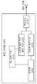
즉, 본 발명의 실시예에 따른 충전 크래들(200)은 외부 전원을 공급받아 변압하여 입력 전압을 공급하는 변압 구조(210), 외부 전원을 기반으로 파워팩(240)을 충전하기 위한 파워팩 충전 구조(230)와 외부 전원을 기반으로 상기 스마트 멀티 카드의 내부 전원을 충전하기 위한 스마트 멀티 카드 충전 구조(220)를 포함할 수 있다.That is, the charging cradle 200 according to an embodiment of the present invention includes a transforming
스마트 멀티 카드의 일면에는 전원을 공급기 위한 제1 접촉 구조가 구현되고, 충전 크래들(200)의 일면에는 상기 제1 접촉 구조와 만나는 제2 접촉 구조(250)가 구현될 수 있다. 외부 전원의 연결시에는 스마트 멀티 카드 충전 구조(220)가 제2 접촉 구조(250)와 연결되고, 외부 전원의 미연결시에는 파워팩 충전 구조(230)가 제2 접촉 구조(250)와 연결될 수 있다. 스마트 멀티 카드 충전 구조(220)와 제2 접촉 구조(250)의 연결 및 파워팩(240)과 제2 접촉 구조(250)의 연결은 외부 전원의 입력 여부를 센싱하여 스위칭될 수 있다.A first contact structure for supplying power may be implemented on one side of the smart card and a
충전 크래들(200)을 기반으로 한 스마트 멀티 카드 및 파워팩(240)의 충전은 다양한 방식으로 수행될 수 있다.The charging of the smart multi card and the
충전 크래들(200)은 외부 전원의 공급시 1차적으로 스마트 멀티 카드 충전 구조(220)를 기반으로 스마트 멀티 카드를 충전하고, 충전 크래들(200)은 스마트 멀티 카드가 완충된 경우, 2차적으로 파워팩 충전 구조(230)를 기반으로 파워팩(240)을 충전할 수 있다.The charging cradle 200 charges the smart multi-card based on the smart multi-card charging structure 220 when the external power is supplied, and the charging cradle 200 charges the smart multi- The
충전 크래들(200)은 외부 전원의 공급시 1차적으로 스마트 멀티 카드 충전 구조(220)를 기반으로 스마트 멀티 카드를 충전하고, 충전 크래들(200)은 스마트 멀티 카드의 충전률이 임계 퍼센티지 이상인 경우, 2차적으로 스마트 멀티 카드 충전 구조(220)와 파워팩 충전 구조(230)를 기반으로 스마트 멀티 카드와 파워팩(240)을 동시에 충전할 수 있고, 스마트 멀티 카드 충전 구조(220)와 파워팩 충전 구조(230)의 동시 충전시 스마트 멀티 카드 충전 구조(220)와 파워팩 충전 구조(230) 각각으로 공급되는 전력은 충전률을 기반으로 변화될 수 있다.The charging cradle 200 charges the smart multi-card based on the smart multi-card charging structure 220 when the external power is supplied, and the charging cradle 200 charges the smart multi-card when the charging rate of the smart multi- The smart multi card recharging structure 220 and the power pack recharging structure 230 can be charged at the same time and the smart multi card recharging structure 220 and the power pack recharging structure 230 The power supplied to each of the smart multi-card charging structure 220 and the power pack charging structure 230 can be changed based on the charging rate.
즉, 충전 크래들(200)로 외부 전원이 공급되는 경우 변압된 제1 전원(입력 전원)을 기반으로 스마트 멀티 카드를 직접적으로 충전시킬 뿐만 아니라, 충전 크래들 내부의 파워팩(240)을 충전시킬 수도 있다. That is, when external power is supplied to the charging cradle 200, the smart card may be directly charged based on the transformed first power (input power), and the
충전 크래들(200)은 외부 전원을 제공받는 케이블과 분리 가능하고, 사용자는 이후 외부 전원 없이도 충전 크래들(200) 내부의 파워팩(240)만을 사용하여 스마트 멀티 카드에 대한 충전을 수행할 수 있다.The charging cradle 200 is detachable from a cable supplied with external power, and the user can then charge the smart multi card using only the
예를 들어, 외부 전원이 연결시에는 파워팩(240)으로부터 스마트 멀티 카드로의 전원 공급이 차단될 수 있다. 반대로 외부 전원이 연결되지 않은 경우, 파워팩(240)으로부터 스마트 멀티 카드로의 전원이 공급될 수 있도록 제1 접촉 구조와 파워팩(240)이 연결될 수 있다.For example, when an external power source is connected, power supply from the
즉, 파워팩(240)이 포함된 충전 크래들이 사용되는 경우, 스마트 멀티 카드는 외부 전원 없이도 충전 크래들 내부의 파워팩(240)을 기반으로 공급되는 전력으로 충전될 수 있다.That is, when the charging cradle including the
도 3은 본 발명의 실시예에 따른 파워팩을 포함하는 충전 크래들 구조를 나타낸 개념도이다.3 is a conceptual diagram illustrating a charging cradle structure including a power pack according to an embodiment of the present invention.
도 3에서는 외부 전원의 연결 여부에 따라 충전 크래들(300)을 연결하는 구조가 개시된다.3, a structure for connecting the charging cradle 300 according to whether an external power source is connected or not is disclosed.
도 3을 참조하면, 충전 크래들(300)을 통해 스마트 멀티 카드와 외부 전원이 연결된 경우, 스마트 멀티 카드의 제1 접촉 구조는 충전 크래들(300)의 제2 접촉 구조(350)와 연결되어 외부 전원으로부터 전력을 공급받을 수 있다.3, when a smart card is connected to an external power source through the charging cradle 300, the first contact structure of the smart card is connected to the
충전 크래들(300)을 통해 스마트 멀티 카드와 외부 전원이 연결되지 않은 경우, 스마트 멀티 카드의 제1 접촉 구조는 충전 크래들(300)의 제2 접촉 구조(350)(또는 파워팩(340)의 제3 접촉 구조)와 연결되어 파워팩(340)으로부터 전력을 공급받을 수 있다.The first contact structure of the smart multi-card is connected to the
외부 전원이 연결된 경우, 파워팩(340)과 제2 접촉 구조(350) 간의 연결이 분리될 수 있다. 일정 전압 크기 이상의 전압이 공급되는 경우, 스위칭을 통해 파워팩(340)과 제2 접촉 구조(350) 간의 연결이 끊어지고, 외부 전원이 스마트 멀티 카드 충전 구조(320)를 통해 제2 접촉 구조(350)와 연결될 수 있다. 반대로 일정 전압 크기 미만이 공급되는 경우, 스위칭을 통해 파워팩(340)과 제2 접촉 구조(350)가 연결되고, 외부 전원과 제2 접촉 구조(350) 간의 연결이 끊어질 수 있다. 스위치는 외부 전원에 의한 전원 공급 여부를 센싱하고, 센싱 결과를 기반으로 on/off될 수 있다.When an external power source is connected, the connection between the
도 3에 개시된 스위치는 임의적인 것으로서 위와 같은 동작을 수행하기 위한 다양한 스위치 구조가 충전 크래들 내부에 구현될 수 있다.The switches disclosed in FIG. 3 are arbitrary and various switch structures for performing the above operation can be implemented inside the charge cradle.
도 4는 본 발명의 실시예에 따른 파워팩과 스마트 멀티 카드의 충전 방법을 나타낸 개념도이다.4 is a conceptual diagram illustrating a charging method of a power pack and a smart multi-card according to an embodiment of the present invention.
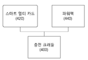
도 4에서는 외부 전원의 연결시 파워팩(440)과 스마트 멀티 카드(420)가 연결될 수 있고, 파워팩(440) 및/또는 스마트 멀티 카드(420)에 대한 충전이 진행될 수 있다.4, the
외부 전원의 연결시 스마트 멀티 카드(420)에 대한 충전이 1차적으로 진행될 수 있다. 외부 전원은 우선적으로 스마트 멀티 카드(420)에 대한 충전을 수행하여 사용자가 완충된 스마트 멀티 카드(420)를 최대한 빠르게 사용하도록 할 수 있다. 스마트 멀티 카드(420)가 완충된 경우, 스마트 멀티 카드(420)는 충전 크래들(400)로 완충되었음을 알리는 제1 충전 완료 신호를 전송할 수 있다. 충전 크래들(400)은 제1 충전 완료 신호를 수신한 이후, 파워팩(440)에 대한 충전을 진행할 수 있다.When the external power source is connected, charging of the
파워팩(440)에 대한 충전이 진행되고, 파워팩(440)에 대한 충전이 완료된 경우, 파워팩(440)은 충전 크래들(400)로 완충되었음을 알리는 제2 충전 완료 신호를 전송할 수 있다. 충전 크래들(400)은 제2 충전 완료 신호를 수신한 이후, 다시 스마트 멀티 카드(420)로 전력을 공급하여 2차 충전을 진행할 수 있다. 충전 크래들(400)은 2차 충전 이후 다시 제1 충전 완료 신호를 수신한다면, 임계 시간 동안 스마트 멀티 카드(420)와 파워팩(440)으로의 전력 공급을 중단할 수 있다.When the charging of the
임계 시간이 흐른뒤, 충전 크래들(400)은 스마트 멀티 카드(420)와 파워팩(440)의 연결 여부를 판단할 수 있다. 충전 크래들(400)에 스마트 멀티 카드(420)와 파워팩(440)이 모두 연결된 경우, 충전 크래들(400)은 스마트 멀티 카드(420)와 파워팩(440)으로의 전원 공급을 전술한 방식으로 재수행할 수 있다.After the critical time has elapsed, the charging
또는 임계 시간이 흐른뒤, 충전 크래들(400)은 스마트 멀티 카드(420)와 파워팩(440)의 연결 여부를 판단할 수 있고, 사용자가 스마트 멀티 카드(420)를 분리하여 파워팩(440)만이 충전 크래들(400)에 연결된 경우, 충전 크래들(400)은 파워팩(440)으로의 전원 공급을 진행하고, 파워팩(440)의 완충 이후, 임계 시간의 경과 여부를 판단하여 파워팩(440)으로의 전원 공급을 다시 진행할 수 있다.The charging
위와 같은 방식으로 시간에 따른 자연 방전으로 인한 스마트 멀티 카드(420) 및 파워팩(440)의 전력 소모를 고려하여 스마트 멀티 카드(420) 및 파워팩(440)을 완충 상태로 유지할 수 있다.The
도 5는 본 발명의 실시예에 따른 파워팩과 스마트 멀티 카드의 충전 방법을 나타낸 개념도이다.5 is a conceptual diagram illustrating a charging method of a power pack and a smart multi-card according to an embodiment of the present invention.
도 5에서는 충전 크래들에 외부 전원의 연결시 파워팩과 스마트 멀티 카드를 순환하여 충전하기 위한 방법이 개시된다.5 illustrates a method for cyclically charging a power pack and a smart multi card when an external power source is connected to the charging cradle.
도 5를 참조하면, 외부 전원을 통해 전력이 스마트 멀티 카드(520) 및 파워팩(540)으로 공급되는 경우, 스마트 멀티 카드(520) 및 파워팩(540)을 충전하기 위한 방법이 개시된다.Referring to FIG. 5, a method for charging a
충전 크래들(500)은 우선적으로 스마트 멀티 카드(520)로 외부 전력을 기반으로 100% 전력을 공급할 수 있다. 스마트 멀티 카드(520)에 제1 임계 퍼센트 이상의 전력이 충전된 경우, 스마트 멀티 카드(520)는 제1 임계 퍼센트 완충 신호를 충전 크래들(500)로 전송할 수 있다.The charging
충전 크래들(500)은 제1 임계 퍼센트 완충 신호의 수신 이후, 스마트 멀티 카드(520)와 파워팩(540)으로 동시에 전력을 공급할 수 있다. 충전 크래들(500)은 스마트 멀티 카드(520)의 충전 상태가 완충에 가까워질수록 스마트 멀티 카드(520)로 공급하는 전력을 상대적으로 감소시키고, 충전 크래들(500)로 공급하는 전력은 상대적으로 증가시킬 수 있다.The charging
충전 크래들(500)은 스마트 멀티 카드(520)의 완충 이후, 스마트 멀티 카드(520)로부터 충전 완료 신호를 수신하고, 파워팩(540)으로 전체 전력을 공급하여 파워팩(540)을 완충시킬 수 있다.The charging
이후, 임계 시간이 흐른뒤, 충전 크래들(500)은 스마트 멀티 카드(520)와 파워팩(540)의 연결 여부를 판단할 수 있다. 충전 크래들(500)에 스마트 멀티 카드(520)와 파워팩(540)이 모두 연결된 경우, 충전 크래들(500)은 스마트 멀티 카드(520)와 파워팩(540)으로의 전원 공급을 전술한 방식으로 재수행할 수 있다.Thereafter, after the threshold time has elapsed, the charging
또는 임계 시간이 흐른뒤, 충전 크래들(500)은 스마트 멀티 카드(520)로와 파워팩(540)의 연결 여부를 판단할 수 있고, 사용자가 스마트 멀티 카드(520)는 분리하여 파워팩(540)만이 충전 크래들(500)에 연결된 경우, 충전 크래들(500)은 파워팩(540)으로의 전원 공급을 진행하고, 파워팩(540)의 완충 이후, 임계 시간의 경과 여부를 판단하여 파워팩(540)으로의 전원 공급을 다시 진행할 수 있다.The charging
이러한 방식으로 스마트 멀티 카드(520)에 대해 우선적으로 충전을 진행하고, 파워팩(540)과 스마트 멀티 카드(520)를 동시에 충전시키는 방식으로 스마트 멀티 카드(520)에 대한 충전 및 파워팩(540)에 대한 충전을 진행할 수 있다.In this manner, the charging for the
도 6은 본 발명의 실시예에 따른 스마트 멀티 카드의 동작을 나타낸 개념도이다.FIG. 6 is a conceptual diagram illustrating an operation of a smart multi-card according to an embodiment of the present invention.
도 6에서는 스마트 멀티 카드의 내부 배터리에서 공급가능한 전력이 임계 비율 미만으로 감소된 경우, 스마트 멀티 카드의 동작이 개시된다.In Fig. 6, when the power available in the internal battery of the smart multi-card is reduced below the threshold ratio, the operation of the smart multi-card is started.
도 6을 참조하면, 스마트 멀티 카드의 내부 배터리에 충전된 전력이 임계 비율 미만으로 감소된 경우, 스마트 멀티 카드는 동작 모드를 변경할 수 있다.Referring to FIG. 6, when the power charged in the internal battery of the smart multi-card is reduced to less than the threshold ratio, the smart multi-card can change the operation mode.
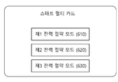
구체적으로 스마트 멀티 카드의 내부 배터리에 충전된 전력이 제1 임계 비율 미만으로 감소된 경우, 스마트 멀티 카드는 동작 모드를 제1 전력 절약 모드(610)로 변경할 수 있다.Specifically, when the power charged in the internal battery of the smart multi-card is reduced below the first threshold ratio, the smart multi-card can change the operation mode to the first power saving mode 610. [
제1 전력 절약 모드(610)에서는 디스플레이 창에 전원을 공급해줄 것을 지시하는 지시자가 표시될 수 있다. 스마트 멀티 카드는 복수의 카드 중 선택된 카드의 카드 정보에 대응되는 마그네틱 신호를 에뮬레이팅한 마그네틱 에뮬레이팅 신호를 제공할 수 있다. 또한, 스마트 멀티 카드는 복수의 카드 중 선택된 카드의 카드 정보에 대응되는 바코드 신호를 디스플레이 창을 통해 표시할 수 있다.In the first power saving mode 610, an indicator for indicating power supply to the display window may be displayed. The smart multi-card can provide a magnetic emulation signal that emulates a magnetic signal corresponding to card information of a selected card among a plurality of cards. In addition, the smart multi-card can display a barcode signal corresponding to card information of a selected card among a plurality of cards through a display window.
제1 전력 절약 모드(610)에서는 마그네틱 에뮬레이팅 신호의 세기의 제1 비율로 감소 및/또는 선택된 카드의 카드 정보를 디스플레이의 밝기가 제1 비율로 감소될 수 있다.In the first power saving mode 610, the brightness of the display may be reduced to a first rate of the magnitude of the magnetic emulation signal and / or the card information of the selected card may be reduced to a first rate.
또한, 스마트 멀티 카드의 내부 배터리에 충전된 전력이 제2 임계 비율 미만으로 감소된 경우, 스마트 멀티 카드는 동작 모드를 제2 전력 절약 모드(620)로 변경할 수 있다. 제2 전력 절약 모드(620)에서는 디스플레이 창에 전원을 공급해줄 것을 지시하는 지시자가 표시될 수 있다. 제2 전력 절약 모드(620)에서는 마그네틱 에뮬레이팅 신호의 세기의 제2 비율로 감소 및/또는 선택된 카드의 카드 정보를 디스플레이의 밝기가 제2 비율로 감소될 수 있다.In addition, if the power charged in the internal battery of the smart multi-card is reduced below the second threshold rate, the smart multi-card can change the operation mode to the second power saving mode 620. [ In the second power saving mode 620, an indicator for indicating power supply to the display window may be displayed. In the second power saving mode 620, the brightness of the display can be reduced to a second rate of intensity of the magnetic emulation signal and / or the card information of the selected card to a second rate.
또한, 스마트 멀티 카드의 내부 배터리에 충전된 전력이 제3 임계 비율 미만으로 감소된 경우, 스마트 멀티 카드는 동작 모드를 제3 전력 절약 모드(630)로 변경할 수 있다. 제3 전력 절약 모드(630)에서는 디스플레이 창에 전원을 공급해줄 것을 지시하는 지시자가 표시될 수 있다. 또한, 제3 전력 절약 모드(630)에서는 마그네틱 에뮬레이팅 신호가 출력되지 않고, 디스플레이 상에서 선택된 카드의 바코드 정보만이 생성되거나, 마그네틱 에뮬레이팅 신호가 출력되고, 디스플레이 상에서 선택된 카드의 바코드 정보가 출력되지 않거나 바코드 정보의 이미지가 일정 크기로 감소되어 제공될 수도 있다.Further, if the power charged in the internal battery of the smart multi-card is reduced to less than the third threshold ratio, the smart multi-card can change the operation mode to the third power saving mode 630. [ In the third power saving mode 630, an indicator for instructing power supply to the display window may be displayed. In the third power saving mode 630, the magnetic emulation signal is not output, only the barcode information of the card selected on the display is generated, the magnetic emulation signal is output, and the barcode information of the selected card on the display is not output Or the image of the barcode information may be reduced to a certain size.
또한 본 발명의 실시예에 따르면 스마트 멀티 카드는 에너지 하베스팅을 기반으로 내부 전원을 충전할 수도 있다. 스마트 멀티 카드의 내부 전원은 에너지 하베스팅을 기반으로 충전이 가능할 수 있다. 예를 들어, 카드 리더기는 무선 신호를 발생시킬 수 있고, 스마트 멀티 카드의 내부 전원은 카드 결제시 무선 신호를 기반으로 에너지 하베스팅 동작을 수행하여 충전될 수 있다. 또한, 스마트 멀티 카드는 무선 스위칭 동작을 기반으로 카드 리더기의 무선 신호를 수신한 이후, 마그네틱 에뮬레이터를 액티브 상태로 전환하여 카드 정보를 제공할 수 있다.Also, according to the embodiment of the present invention, the smart multi-card may charge internal power based on energy harvesting. The internal power of the smart card can be charged based on energy harvesting. For example, the card reader may generate a wireless signal, and the internal power source of the smart multi-card may be charged by performing an energy harvesting operation based on a wireless signal at the time of card settlement. In addition, the smart multi-card can provide the card information by switching the magnetic emulator to the active state after receiving the wireless signal of the card reader based on the wireless switching operation.
이러한 에너지 하베스팅 동작이 수행되는 경우, 스마트 멀티 카드의 전력 상태에 따라 에너지 하베스팅을 위한 시간이 다르게 설정될 수 있다. 에너지 하베스팅 량을 조절하기 위해 스마트 멀티 카드는 고의적으로 결제 카드 정보를 카드 결제기와 일정 시간 동안 접촉 이후 제공할 수도 있다.When this energy harvesting operation is performed, the time for energy harvesting may be set differently depending on the power state of the smart multi-card. To control the amount of energy harvesting, the smart card may intentionally provide payment card information after contact with the card dispenser for a period of time.
예를 들어, 스마트 멀티카드에 저장된 전력의 양이 작은 경우, 카드 리더기와의 접촉 시간을 상대적으로 더 가질 수 있도록 설정하여 카드 리더기에 의해 발생되는 무선 신호를 기반으로 한 충전 시간이 상대적으로 더 길어지도록 할 수 있다. 또한, 본 발명에서는 기존의 카드 결제 시간 등을 고려하여 내부 전원에 대한 충전을 위한 카드리더기와의 접촉 시간을 다르게 설정할 수도 있다. 예를 들어, 카드 결제 및 스마트 멀티 카드의 사용이 아침 9시 이후 저녁 9시 이전에 상대적으로 많이 발생되고, 저녁 9시 이후 아침 9시 이전에는 상대적으로 적게 발생되는 경우가 가정될 수 있다. 이러한 경우, 카드 사용량을 예측하여 카드 사용량에 따른 전력 소비량을 예측하여 에너지 하베스팅을 위한 시간을 조절할 수 있다.For example, when the amount of power stored in the smart card is small, the contact time with the card reader is set to be relatively longer, and the charging time based on the wireless signal generated by the card reader is relatively long . In addition, in the present invention, the contact time with the card reader for charging the internal power source may be set differently in consideration of the existing card settlement time. For example, it can be assumed that the use of card payment and smart multi-card is relatively frequent before 9:00 am after 9:00 am, and relatively few after 9:00 pm and before 9:00 am. In such a case, the time for energy harvesting can be adjusted by predicting the amount of card usage and estimating the power consumption according to the card usage amount.
이상 설명된 본 발명에 따른 실시예는 다양한 컴퓨터 구성요소를 통하여 실행될 수 있는 프로그램 명령어의 형태로 구현되어 컴퓨터 판독 가능한 기록 매체에 기록될 수 있다. 상기 컴퓨터 판독 가능한 기록 매체는 프로그램 명령어, 데이터 파일, 데이터 구조 등을 단독으로 또는 조합하여 포함할 수 있다. 상기 컴퓨터 판독 가능한 기록 매체에 기록되는 프로그램 명령어는 본 발명을 위하여 특별히 설계되고 구성된 것이거나 컴퓨터 소프트웨어 분야의 당업자에게 공지되어 사용 가능한 것일 수 있다. 컴퓨터 판독 가능한 기록 매체의 예에는, 하드 디스크, 플로피 디스크 및 자기 테이프와 같은 자기 매체, CD-ROM 및 DVD와 같은 광기록 매체, 플롭티컬 디스크(floptical disk)와 같은 자기-광 매체(magneto-optical medium), 및 ROM, RAM, 플래시 메모리 등과 같은, 프로그램 명령어를 저장하고 실행하도록 특별히 구성된 하드웨어 장치가 포함된다. 프로그램 명령어의 예에는, 컴파일러에 의하여 만들어지는 것과 같은 기계어 코드뿐만 아니라 인터프리터 등을 사용하여 컴퓨터에 의해서 실행될 수 있는 고급 언어 코드도 포함된다. 하드웨어 장치는 본 발명에 따른 처리를 수행하기 위하여 하나 이상의 소프트웨어 모듈로 변경될 수 있으며, 그 역도 마찬가지이다.The embodiments of the present invention described above can be implemented in the form of program instructions that can be executed through various computer components and recorded in a computer-readable recording medium. The computer-readable recording medium may include program commands, data files, data structures, and the like, alone or in combination. The program instructions recorded on the computer-readable recording medium may be those specifically designed and configured for the present invention or may be those known and used by those skilled in the computer software arts. Examples of computer-readable media include magnetic media such as hard disks, floppy disks and magnetic tape, optical recording media such as CD-ROM and DVD, magneto-optical media such as floptical disks, medium, and hardware devices specifically configured to store and execute program instructions, such as ROM, RAM, flash memory, and the like. Examples of program instructions include machine language code, such as those generated by a compiler, as well as high-level language code that can be executed by a computer using an interpreter or the like. The hardware device may be modified into one or more software modules for performing the processing according to the present invention, and vice versa.
이상에서 본 발명이 구체적인 구성요소 등과 같은 특정 사항과 한정된 실시예 및 도면에 의하여 설명되었으나, 이는 본 발명의 보다 전반적인 이해를 돕기 위하여 제공된 것일 뿐, 본 발명이 상기 실시예에 한정되는 것은 아니며, 본 발명이 속하는 기술분야에서 통상적인 지식을 가진 자라면 이러한 기재로부터 다양한 수정과 변경을 꾀할 수 있다.While the present invention has been particularly shown and described with reference to exemplary embodiments thereof, it is to be understood that the invention is not limited to the disclosed embodiments, but, on the contrary, Those skilled in the art will appreciate that various modifications and changes may be made thereto without departing from the scope of the present invention.
따라서, 본 발명의 사상은 상기 설명된 실시예에 국한되어 정해져서는 아니 되며, 후술하는 특허청구범위뿐만 아니라 이 특허청구범위와 균등한 또는 이로부터 등가적으로 변경된 모든 범위는 본 발명의 사상의 범주에 속한다고 할 것이다.Accordingly, the spirit of the present invention should not be construed as being limited to the above-described embodiments, and all ranges that are equivalent to or equivalent to the claims of the present invention as well as the claims .
Claims (10)
외부 전원을 공급받아 변압하여 입력 전압을 공급하는 변압 구조;
상기 외부 전원을 기반으로 파워팩을 충전하기 위한 파워팩 충전 구조; 및
상기 외부 전원을 기반으로 상기 스마트 멀티 카드의 내부 전원을 충전하기 위한 스마트 멀티 카드 충전 구조를 포함하는 것을 특징으로 충전 크래들.The charging cradle for charging the smart multi-
A transformer structure that receives external power and transforms the voltage to supply an input voltage;
A power pack charging structure for charging the power pack based on the external power source; And
And a smart multi-card charging structure for charging the internal power of the smart multi-card based on the external power.
상기 스마트 멀티 카드의 일면에는 전원을 공급기 위한 제1 접촉 구조가 구현되고,
상기 충전 크래들의 일면에는 상기 제1 접촉 구조와 만나는 제2 접촉 구조가 구현되고,
상기 외부 전원의 연결시에는 상기 스마트 멀티 카드 충전 구조가 상기 제2 접촉 구조와 연결되고,
상기 외부 전원의 미연결시에는 상기 파워팩 충전 구조가 상기 제2 접촉 구조와 연결되는 것을 특징으로 하는 충전 크래들.The method according to claim 1,
A first contact structure for supplying power is implemented on one side of the smart multi card,
A second contact structure that meets the first contact structure is implemented on one surface of the charging cradle,
When the external power source is connected, the smart card charging structure is connected to the second contact structure,
And when the external power source is not connected, the power pack charging structure is connected to the second contact structure.
상기 스마트 멀티 카드 충전 구조와 상기 제2 접촉 구조의 연결 및 상기 파워팩 구조와 상기 제2 접촉 구조의 연결은 상기 외부 전원의 입력 여부를 센싱하여 스위칭되는 것을 특징으로 하는 방법.3. The method of claim 2,
Wherein the connection between the smart multi-card charging structure and the second contact structure and the connection between the power pack structure and the second contact structure are switched by sensing whether the external power source is input.
상기 충전 크래들은 상기 외부 전원의 공급시 1차적으로 상기 스마트 멀티 카드 충전 구조를 기반으로 상기 스마트 멀티 카드를 충전하고,
상기 충전 크래들은 상기 스마트 멀티 카드가 완충된 경우, 2차적으로 상기 파워팩 충전 구조를 기반으로 상기 파워팩을 충전하는 것을 특징으로 하는 충전 크래들.The method of claim 3,
Wherein the charging cradle charges the smart multi-card based on the smart multi-card charging structure when the external power is supplied,
Wherein the charging cradle charges the power pack based on the power pack charging structure when the smart multi card is fully charged.
상기 충전 크래들은 상기 외부 전원의 공급시 1차적으로 상기 스마트 멀티 카드 충전 구조를 기반으로 상기 스마트 멀티 카드를 충전하고,
상기 충전 크래들은 상기 스마트 멀티 카드의 충전률이 임계 퍼센티지 이상인 경우, 2차적으로 상기 스마트 멀티 카드 충전 구조와 상기 파워팩 충전 구조를 기반으로 상기 스마트 멀티 카드와 상기 파워팩을 동시에 충전하고,
상기 스마트 멀티 카드 충전 구조와 상기 파워팩 충전 구조의 동시 충전시 상기 스마트 멀티 카드 충전 구조와 상기 파워팩 충전 구조 각각으로 공급되는 전력은 상기 충전률을 기반으로 변화되는 것을 특징으로 하는 충전 크래들.The method of claim 3,
Wherein the charging cradle charges the smart multi-card primarily based on the smart multi-card charging structure when the external power is supplied,
Wherein the charging cradle simultaneously charges the smart multi card and the power pack based on the smart multi card charging structure and the power pack charging structure when the charging rate of the smart multi card is equal to or greater than a threshold percentage,
Wherein the power supplied to each of the smart multi-card charging structure and the power pack charging structure during simultaneous charging of the smart multi-card charging structure and the power pack charging structure is changed based on the charging rate.
변압 구조가 외부 전원을 공급받아 변압하여 입력 전압을 공급하는 단계;
파워팩 충전 구조가 상기 외부 전원을 기반으로 파워팩을 충전하는 단계;
스마트 멀티 카드 충전 구조가 상기 외부 전원을 기반으로 상기 스마트 멀티 카드의 내부 전원을 충전하는 단계를 포함하는 것을 특징으로 하는 방법.The charging method of the charging cradle for charging the smart multi-
Supplying the input voltage by transforming the transformer structure by receiving external power;
Charging the power pack based on the external power source;
Wherein the smart multi-card charging structure charges the internal power of the smart multi-card based on the external power source.
상기 스마트 멀티 카드의 일면에는 전원을 공급기 위한 제1 접촉 구조가 구현되고,
상기 충전 크래들의 일면에는 상기 제1 접촉 구조와 만나는 제2 접촉 구조가 구현되고,
상기 외부 전원의 연결시에는 상기 스마트 멀티 카드 충전 구조가 상기 제2 접촉 구조와 연결되고,
상기 외부 전원의 미연결시에는 상기 파워팩 충전 구조가 상기 제2 접촉 구조와 연결되는 것을 특징으로 하는 방법.The method according to claim 6,
A first contact structure for supplying power is implemented on one side of the smart multi card,
A second contact structure that meets the first contact structure is implemented on one surface of the charging cradle,
When the external power source is connected, the smart card charging structure is connected to the second contact structure,
And when the external power source is not connected, the power pack charging structure is connected to the second contact structure.
상기 스마트 멀티 카드 충전 구조와 상기 제2 접촉 구조의 연결 및 상기 파워팩 구조와 상기 제2 접촉 구조의 연결은 상기 외부 전원의 입력 여부를 센싱하여 스위칭되는 것을 특징으로 하는 방법.8. The method of claim 7,
Wherein the connection between the smart multi-card charging structure and the second contact structure and the connection between the power pack structure and the second contact structure are switched by sensing whether the external power source is input.
상기 충전 크래들은 상기 외부 전원의 공급시 1차적으로 상기 스마트 멀티 카드 충전 구조를 기반으로 상기 스마트 멀티 카드를 충전하고,
상기 충전 크래들은 상기 스마트 멀티 카드가 완충된 경우, 2차적으로 상기 파워팩 충전 구조를 기반으로 상기 파워팩을 충전하는 것을 특징으로 하는 방법.9. The method of claim 8,
Wherein the charging cradle charges the smart multi-card based on the smart multi-card charging structure when the external power is supplied,
Wherein the charging cradle charges the power pack based on the power pack charging structure when the smart multi card is fully charged.
상기 충전 크래들은 상기 외부 전원의 공급시 1차적으로 상기 스마트 멀티 카드 충전 구조를 기반으로 상기 스마트 멀티 카드를 충전하고,
상기 충전 크래들은 상기 스마트 멀티 카드의 충전률이 임계 퍼센티지 이상인 경우, 2차적으로 상기 스마트 멀티 카드 충전 구조와 상기 파워팩 충전 구조를 기반으로 상기 스마트 멀티 카드와 상기 파워팩을 동시에 충전하고,
상기 스마트 멀티 카드 충전 구조와 상기 파워팩 충전 구조의 동시 충전시 상기 스마트 멀티 카드 충전 구조와 상기 파워팩 충전 구조 각각으로 공급되는 전력은 상기 충전률을 기반으로 변화되는 것을 특징으로 하는 방법.9. The method of claim 8,
Wherein the charging cradle charges the smart multi-card primarily based on the smart multi-card charging structure when the external power is supplied,
Wherein the charging cradle simultaneously charges the smart multi card and the power pack based on the smart multi card charging structure and the power pack charging structure when the charging rate of the smart multi card is equal to or greater than a threshold percentage,
Wherein the power supplied to each of the smart multi-card charging structure and the power pack charging structure during simultaneous charging of the smart multi-card charging structure and the power pack charging structure is changed based on the charging rate.
Priority Applications (1)
| Application Number | Priority Date | Filing Date | Title |
|---|---|---|---|
| PCT/KR2018/002148 WO2018155911A1 (en) | 2017-02-25 | 2018-02-21 | Method for charging smart multi-card, and charging cradle for performing said method |
Applications Claiming Priority (2)
| Application Number | Priority Date | Filing Date | Title |
|---|---|---|---|
| KR20170025135 | 2017-02-25 | ||
| KR1020170025135 | 2017-02-25 |
Publications (1)
| Publication Number | Publication Date |
|---|---|
| KR20180098474A true KR20180098474A (en) | 2018-09-04 |
Family
ID=63598456
Family Applications (1)
| Application Number | Title | Priority Date | Filing Date |
|---|---|---|---|
| KR1020180020557A Ceased KR20180098474A (en) | 2017-02-25 | 2018-02-21 | Method for charging smart-multi card and charging cradle performing the method |
Country Status (1)
| Country | Link |
|---|---|
| KR (1) | KR20180098474A (en) |
Cited By (1)
| Publication number | Priority date | Publication date | Assignee | Title |
|---|---|---|---|---|
| WO2024129115A1 (en) * | 2022-12-11 | 2024-06-20 | Visa International Service Association | Vicinity use card |
-
2018
- 2018-02-21 KR KR1020180020557A patent/KR20180098474A/en not_active Ceased
Cited By (1)
| Publication number | Priority date | Publication date | Assignee | Title |
|---|---|---|---|---|
| WO2024129115A1 (en) * | 2022-12-11 | 2024-06-20 | Visa International Service Association | Vicinity use card |
Similar Documents
| Publication | Publication Date | Title |
|---|---|---|
| KR101613855B1 (en) | Multi smart card | |
| KR101728523B1 (en) | Smart multi card and method for issuing card data | |
| US10380471B2 (en) | Dynamic transaction card power management | |
| US9870557B2 (en) | Payment object reader device with multiple types of reader circuitry | |
| US20190220719A1 (en) | Dynamic transaction card power management | |
| US20030019942A1 (en) | System and method for electronically readable card having power source | |
| CN107533656A (en) | Antenna decoupled from programmable smart card | |
| US20180102812A1 (en) | Recharging an electronic device using an nfc front end | |
| US20150254621A1 (en) | Settlement terminal device | |
| JP2020046941A (en) | IC card and portable electronic device | |
| KR20180098474A (en) | Method for charging smart-multi card and charging cradle performing the method | |
| KR20180097460A (en) | Method for controlling smart-multi card and smart-multicard using the method | |
| KR20170121086A (en) | Smart card and control method thereof and charging apparatus therefor and smart card reader | |
| CN102306434A (en) | Mobile POS (point of sales) machine | |
| KR20160145298A (en) | Multi card for combining mobile device | |
| KR20190143610A (en) | Smart card | |
| KR20190046342A (en) | Method for controlling power of smart-multi card and apparatus for performing the method | |
| KR20170123744A (en) | Smart multi card with plural track | |
| CN105989381B (en) | Truth cards manager | |
| KR101577251B1 (en) | Multi-variable magnetic field generator and a multi-magnet stripe card | |
| KR20170003134U (en) | Multi-card | |
| CN105989382A (en) | Real card management device and data interaction method |
Legal Events
| Date | Code | Title | Description |
|---|---|---|---|
| A201 | Request for examination | ||
| PA0109 | Patent application |
St.27 status event code: A-0-1-A10-A12-nap-PA0109 |
|
| PA0201 | Request for examination |
St.27 status event code: A-1-2-D10-D11-exm-PA0201 |
|
| R18-X000 | Changes to party contact information recorded |
St.27 status event code: A-3-3-R10-R18-oth-X000 |
|
| PG1501 | Laying open of application |
St.27 status event code: A-1-1-Q10-Q12-nap-PG1501 |
|
| E902 | Notification of reason for refusal | ||
| PE0902 | Notice of grounds for rejection |
St.27 status event code: A-1-2-D10-D21-exm-PE0902 |
|
| E601 | Decision to refuse application | ||
| PE0601 | Decision on rejection of patent |
St.27 status event code: N-2-6-B10-B15-exm-PE0601 |
|
| R18-X000 | Changes to party contact information recorded |
St.27 status event code: A-3-3-R10-R18-oth-X000 |
|
| P22-X000 | Classification modified |
St.27 status event code: A-2-2-P10-P22-nap-X000 |
|
| P22-X000 | Classification modified |
St.27 status event code: A-2-2-P10-P22-nap-X000 |