KR20180098456A - United apparatus for implementing shift lock and shift lock release of automatic transmission vehicle - Google Patents
United apparatus for implementing shift lock and shift lock release of automatic transmission vehicle Download PDFInfo
- Publication number
- KR20180098456A KR20180098456A KR1020170025027A KR20170025027A KR20180098456A KR 20180098456 A KR20180098456 A KR 20180098456A KR 1020170025027 A KR1020170025027 A KR 1020170025027A KR 20170025027 A KR20170025027 A KR 20170025027A KR 20180098456 A KR20180098456 A KR 20180098456A
- Authority
- KR
- South Korea
- Prior art keywords
- shift lock
- shift
- plunger
- lever
- lock release
- Prior art date
- Legal status (The legal status is an assumption and is not a legal conclusion. Google has not performed a legal analysis and makes no representation as to the accuracy of the status listed.)
- Granted
Links
Images


Classifications
-
- F—MECHANICAL ENGINEERING; LIGHTING; HEATING; WEAPONS; BLASTING
- F16—ENGINEERING ELEMENTS AND UNITS; GENERAL MEASURES FOR PRODUCING AND MAINTAINING EFFECTIVE FUNCTIONING OF MACHINES OR INSTALLATIONS; THERMAL INSULATION IN GENERAL
- F16H—GEARING
- F16H59/00—Control inputs to control units of change-speed- or reversing-gearings for conveying rotary motion
- F16H59/02—Selector apparatus
- F16H59/08—Range selector apparatus
- F16H59/10—Range selector apparatus comprising levers
- F16H59/105—Range selector apparatus comprising levers consisting of electrical switches or sensors
-
- F—MECHANICAL ENGINEERING; LIGHTING; HEATING; WEAPONS; BLASTING
- F16—ENGINEERING ELEMENTS AND UNITS; GENERAL MEASURES FOR PRODUCING AND MAINTAINING EFFECTIVE FUNCTIONING OF MACHINES OR INSTALLATIONS; THERMAL INSULATION IN GENERAL
- F16H—GEARING
- F16H59/00—Control inputs to control units of change-speed- or reversing-gearings for conveying rotary motion
- F16H59/02—Selector apparatus
- F16H59/0278—Constructional features of the selector lever, e.g. grip parts, mounting or manufacturing
-
- F—MECHANICAL ENGINEERING; LIGHTING; HEATING; WEAPONS; BLASTING
- F16—ENGINEERING ELEMENTS AND UNITS; GENERAL MEASURES FOR PRODUCING AND MAINTAINING EFFECTIVE FUNCTIONING OF MACHINES OR INSTALLATIONS; THERMAL INSULATION IN GENERAL
- F16H—GEARING
- F16H61/00—Control functions within control units of change-speed- or reversing-gearings for conveying rotary motion ; Control of exclusively fluid gearing, friction gearing, gearings with endless flexible members or other particular types of gearing
- F16H61/22—Locking of the control input devices
-
- F—MECHANICAL ENGINEERING; LIGHTING; HEATING; WEAPONS; BLASTING
- F16—ENGINEERING ELEMENTS AND UNITS; GENERAL MEASURES FOR PRODUCING AND MAINTAINING EFFECTIVE FUNCTIONING OF MACHINES OR INSTALLATIONS; THERMAL INSULATION IN GENERAL
- F16H—GEARING
- F16H59/00—Control inputs to control units of change-speed- or reversing-gearings for conveying rotary motion
- F16H59/02—Selector apparatus
- F16H2059/0221—Selector apparatus for selecting modes, e.g. sport, normal, economy
-
- F—MECHANICAL ENGINEERING; LIGHTING; HEATING; WEAPONS; BLASTING
- F16—ENGINEERING ELEMENTS AND UNITS; GENERAL MEASURES FOR PRODUCING AND MAINTAINING EFFECTIVE FUNCTIONING OF MACHINES OR INSTALLATIONS; THERMAL INSULATION IN GENERAL
- F16H—GEARING
- F16H59/00—Control inputs to control units of change-speed- or reversing-gearings for conveying rotary motion
- F16H59/02—Selector apparatus
- F16H2059/026—Details or special features of the selector casing or lever support
-
- F—MECHANICAL ENGINEERING; LIGHTING; HEATING; WEAPONS; BLASTING
- F16—ENGINEERING ELEMENTS AND UNITS; GENERAL MEASURES FOR PRODUCING AND MAINTAINING EFFECTIVE FUNCTIONING OF MACHINES OR INSTALLATIONS; THERMAL INSULATION IN GENERAL
- F16H—GEARING
- F16H59/00—Control inputs to control units of change-speed- or reversing-gearings for conveying rotary motion
- F16H59/02—Selector apparatus
- F16H59/0278—Constructional features of the selector lever, e.g. grip parts, mounting or manufacturing
- F16H2059/0282—Lever handles with lock mechanisms, e.g. for allowing selection of reverse gear or releasing lever from park position
-
- F—MECHANICAL ENGINEERING; LIGHTING; HEATING; WEAPONS; BLASTING
- F16—ENGINEERING ELEMENTS AND UNITS; GENERAL MEASURES FOR PRODUCING AND MAINTAINING EFFECTIVE FUNCTIONING OF MACHINES OR INSTALLATIONS; THERMAL INSULATION IN GENERAL
- F16H—GEARING
- F16H61/00—Control functions within control units of change-speed- or reversing-gearings for conveying rotary motion ; Control of exclusively fluid gearing, friction gearing, gearings with endless flexible members or other particular types of gearing
- F16H61/22—Locking of the control input devices
- F16H2061/223—Electrical gear shift lock, e.g. locking of lever in park or neutral position by electric means if brake is not applied; Key interlock, i.e. locking the key if lever is not in park position
-
- F—MECHANICAL ENGINEERING; LIGHTING; HEATING; WEAPONS; BLASTING
- F16—ENGINEERING ELEMENTS AND UNITS; GENERAL MEASURES FOR PRODUCING AND MAINTAINING EFFECTIVE FUNCTIONING OF MACHINES OR INSTALLATIONS; THERMAL INSULATION IN GENERAL
- F16H—GEARING
- F16H61/00—Control functions within control units of change-speed- or reversing-gearings for conveying rotary motion ; Control of exclusively fluid gearing, friction gearing, gearings with endless flexible members or other particular types of gearing
- F16H61/22—Locking of the control input devices
- F16H2061/226—Manual distress release of the locking means for shift levers, e.g. to allow towing of vehicle in case of breakdown
-
- F—MECHANICAL ENGINEERING; LIGHTING; HEATING; WEAPONS; BLASTING
- F16—ENGINEERING ELEMENTS AND UNITS; GENERAL MEASURES FOR PRODUCING AND MAINTAINING EFFECTIVE FUNCTIONING OF MACHINES OR INSTALLATIONS; THERMAL INSULATION IN GENERAL
- F16H—GEARING
- F16H59/00—Control inputs to control units of change-speed- or reversing-gearings for conveying rotary motion
- F16H59/50—Inputs being a function of the status of the machine, e.g. position of doors or safety belts
- F16H59/54—Inputs being a function of the status of the machine, e.g. position of doors or safety belts dependent on signals from the brakes, e.g. parking brakes
Landscapes
- Engineering & Computer Science (AREA)
- General Engineering & Computer Science (AREA)
- Mechanical Engineering (AREA)
- Arrangement Or Mounting Of Control Devices For Change-Speed Gearing (AREA)
Abstract
본 발명은 자동변속기 차량의 시프트 락 및 시프트 락 릴리즈를 구현하기 위한 일체형 장치에 관한 것으로, 시프트 락 솔레노이드와 시프트 락 릴리즈레버가 1개의 케이스에 의해서 일체형으로 모듈화된 구성이면서, 시프트 락 솔레노이드만을 사용해서 시프트 락의 기능을 구현하고, 시프트 락 릴리즈 레버가 시프트 락 솔레노이드를 직접 작동시키서 시프트 락 릴리즈 기능을 구현할 수 있도록 된 것이다.The present invention relates to an integrated device for implementing a shift lock and a shift lock release of an automatic transmission vehicle, in which a shift lock solenoid and a shift lock release lever are integrally modularized by a single case while using only a shift lock solenoid The shift lock function is realized and the shift lock release lever can operate the shift lock solenoid directly to implement the shift lock release function.
Description
본 발명은 시프트 락 솔레노이드와 시프트 락 릴리즈레버가 1개의 케이스에 의해서 일체형으로 모듈화된 자동변속기 차량의 시프트 락 및 시프트 락 릴리즈를 구현하기 위한 일체형 장치에 관한 기술이다.The present invention relates to an integrated device for implementing a shift lock and a shift lock release of an automatic transmission vehicle in which a shift lock solenoid and a shift lock release lever are modularly integrated by a single case.
자동변속기의 차량에서 운전석 주변에 위치하도록 설치된 시프트레버는 운전자의 조작시 디텐트플레이트에 형성된 레인지(range)의 홈을 따라 이동하면서 P(파킹)단, R(후진)단, N(중립)단, D(주행)단 중 어느 하나에 선택적으로 위치할 수 있도록 하단이 회전 가능하게 힌지 결합되어 설치된다.The shift lever installed in the vicinity of the driver's seat in the vehicle of the automatic transmission moves along the groove of the range formed on the detent plate during operation of the driver, , And a D (driving) stage, respectively, so that the lower ends thereof can be selectively positioned.
한편, 자동변속기 차량은 운전자가 브레이크페달을 밟지 않으면 시프트레버의 P → R단 시프트가 불가능하도록 한 시프트 락 기능이 함께 구비되어 있는 바, 이러한 시프트 락 기능으로 인해 운전자의 부주의로 인한 안전사고의 발생을 미리 예방할 수 있도록 되어 있다.On the other hand, the automatic transmission vehicle is equipped with a shift lock function which prevents the shift lever from being shifted P → R when the driver does not step on the brake pedal. This shift lock function causes a safety accident Can be prevented in advance.
시프트 락의 기능을 구현하기 위한 장치는 시프트 락 솔레노이드 및 시프트 락 레버로 구성된다.An apparatus for implementing the function of a shift lock is composed of a shift lock solenoid and a shift lock lever.
시프트레버가 P단에 위치하고 있고 운전자가 브레이크페달을 밟지 않은 상태일 때, 시프트 락 레버의 일단은 시프트레버의 몸체에 걸려진 상태를 유지하게 됨으로써 시프트레버가 P단의 위치에서 R단 또는 다른 변속단으로 원치않게 변경되는 것을 방지하게 된다.When the shift lever is positioned at the P-end and the driver does not step on the brake pedal, one end of the shift lock lever remains engaged with the body of the shift lever, so that the shift lever is moved from the P- Thereby preventing unwanted changes.
그리고, 시프트레버가 P단에 위치한 상태에서 운전자가 브레이크페달을 밟으면, 센서가 브레이크페달의 작동상태를 검출해서 콘트롤러(BCM, Body Control Module)로 전송하고, BCM의 제어에 의해 시프트 락 솔레노이드가 동작하며, 시프트 락 솔레노이드의 동작에 연동하여 시프트 락 레버가 동작하게 되는 바, 따라서 시프트레버의 몸체에 걸려져 있던 시프트 락 레버의 일단이 해제됨으로써 시프트레버의 락이 해제되고, 이에 따라 시프트레버는 운전자의 의지대로 P단의 위치에서 R단 또는 다른 변속단으로 이동이 가능한 상태가 되는 것이다.Then, when the driver depresses the brake pedal while the shift lever is located at the P-end, the sensor detects the operation state of the brake pedal and transmits the brake pedal to the controller (BCM, Body Control Module), and the shift lock solenoid Accordingly, the shift lock lever is operated in conjunction with the operation of the shift lock solenoid. Thus, the one end of the shift lock lever held in the body of the shift lever is released to release the lock of the shift lever, It is in a state in which it is possible to move from the position of the P-stage to the R-stage or the other gear position as it is.
또한, 자동변속기 차량은 전술한 시프트 락 기능 외에 시프트 락 릴리즈 기능을 더 구비하고 있는 바, 상기 시프트 락 릴리즈 기능은 시프트레버가 P단에 위치한 상태에서 운전자가 브레이크페달을 밟은 상태일지라도 시프트 락 솔레노이드 등의 고장으로 인해 시프트 락이 해제되지 못하는 경우 사용하는 기능이다.In addition, the automatic transmission vehicle further includes a shift lock release function in addition to the above-described shift lock function. In the shift lock release function, even if the driver depresses the brake pedal while the shift lever is positioned at the P- When the shift lock can not be released due to a failure of the shift lever.
시프트 락 릴리즈 기능의 구현을 위해 시프트 락 릴리즈 레버가 구비되고, 시프트 락 릴리즈 레버의 수동 조작시 시프트 락 솔레노이드의 플런저가 강제로 움직이고, 이에 따라 시프트레버의 몸체에 걸려져 있던 시프트 락 레버의 일단이 강제로 해제됨으로써 시프트레버의 락 상태를 해제시키는 것이다.The shift lock release lever is provided for realizing the shift lock release function and the plunger of the shift lock solenoid forcibly moves during the manual operation of the shift lock release lever so that one end of the shift lock lever held in the body of the shift lever So that the locked state of the shift lever is released.
그런데, 종래의 구조는 시프트 락 솔레노이드 및 시프트 락 레버가 각각 독립적인 위치에서 서로 연결구조를 갖도록 설치되고, 또한 시프트 락 레버 및 시프트 락 릴리즈 레버도 각각 독립적인 위치에서 서로 연결구조를 갖도록 설치된 구조로, 즉 3개 부품인 시프트 락 솔레노이드와 시프트 락 레버 및 시프트 락 릴리즈 레버가 각각 개별적으로 구분된 위치에 설치된 구조로, 이에 따라 각각의 부품마다 개별적으로 설치공간을 확보해야 하는 단점이 있고, 시프트레버와의 조립시 전체적인 사이즈가 커지는 단점이 있다.However, in the conventional structure, the shift lock solenoid and the shift lock lever are provided so as to have a connection structure with each other at independent positions, and the shift lock lever and the shift lock release lever are also provided so as to have connection structures at independent positions A shift lock solenoid, a shift lock lever, and a shift lock release lever are separately provided at positions where the shift lock solenoid, the shift lock lever, and the shift lock release lever are separately provided. There is a disadvantage in that the overall size is increased when assembled with the motor.
또한, 3개 부품인 시프트 락 솔레노이드와 시프트 락 레버 및 시프트 락 릴리즈 레버가 각각 개별적으로 구분된 위치에서 서로 연결구조를 갖도록 조립됨에 따라 부품간 연결부위에 조립 공차에 따른 산포가 커서 품질 확보에 어려움이 있는 단점이 있고, 이로 인해 시프트 락 또는 시프트 락 릴리즈 작동시 응답속도가 느려서 품질문제를 야기하는 단점도 있다.In addition, since the three parts, the shift lock solenoid, the shift lock lever, and the shift lock release lever are assembled so as to have a mutual connection structure at positions where they are individually separated, There is a disadvantage that the response speed is slow when the shift lock or the shift lock release operation is performed, thereby causing a quality problem.
또한, 전술한 바와 같은 개별적인 조립구조로 인해 조립시간의 과다소요 및 생산성의 감소의 원인이 되는 단점도 있다.In addition, there is also a disadvantage that it causes an excessive assembly time and a decrease in productivity due to the individual assembling structure as described above.
상기의 배경기술로서 설명된 사항들은 본 발명의 배경에 대한 이해 증진을 위한 것일 뿐, 이 기술분야에서 통상의 지식을 가진 자에게 이미 알려진 종래기술에 해당함을 인정하는 것으로 받아들여져서는 안 될 것이다.It should be understood that the foregoing description of the background art is merely for the purpose of promoting an understanding of the background of the present invention and is not to be construed as an admission that the prior art is known to those skilled in the art.
본 발명은, 시프트 락의 기능 및 시프트 락 릴리즈의 기능을 구현하기 위한 시프트 락 솔레노이드와 시프트 락 릴리즈레버가 1개의 케이스에 의해서 일체형으로 모듈화된 자동변속기 차량의 시프트 락 및 시프트 락 릴리즈를 구현하기 위한 일체형 장치를 제공한 것으로, 이를 통해 설치공간의 확보를 최소화함에 따라 전체적인 사이즈 축소 및 경량화를 도모할 수 있도록 하고, 조립에 따른 산포를 크게 줄일 수 있게 됨에 따라 우수한 품질을 확보할 수 있도록 하며, 더 나아가 시프트 락 또는 시프트 락 릴리즈 작동시 빠른 응답속도를 확보함으로써 품질 향상을 도모할 수 있도록 하는 데에 그 목적이 있다.A shift lock solenoid and a shift lock release lever for implementing the function of a shift lock and a shift lock release function are provided for implementing a shift lock and a shift lock release of an automatic transmission vehicle that are integrally modularized by a single case The present invention provides an integrated device capable of minimizing the size of the installation space and reducing the overall size and weight of the device, Furthermore, the present invention aims to improve the quality by securing a quick response speed in shift lock or shift lock release operation.
또한, 본 발명은 시프트 락 솔레노이드만을 사용해서 시프트 락의 기능을 구현하고, 또한 시프트 락 릴리즈 레버가 시프트 락 솔레노이드를 직접 작동시키서 시프트 락 릴리즈 기능을 구현할 수 있도록 한 구조로, 이를 통해 종래에 사용하던 시프트 락 레버의 사용을 없앨 수 있게 됨으로써 부품수 감축과 원가절감 및 중량감소를 도모하고, 더 나아가 조립시간의 단축을 통해 생산성 향상을 도모할 수 있도록 하는 데에 다른 목적이 있다.In addition, the present invention realizes the function of a shift lock using only a shift lock solenoid, and also enables a shift lock release lever to implement a shift lock release function by directly operating a shift lock solenoid. It is possible to eliminate the use of the shift lock lever, thereby reducing the number of parts, reducing the cost and weight, and further improving the productivity by shortening the assembly time.
상기한 바의 목적을 달성하기 위한 본 발명 자동변속기 차량의 시프트 락 및 시프트 락 릴리즈를 구현하기 위한 일체형 장치는, 진퇴이동이 가능한 플런저를 구비한 시프트 락 솔레노이드; 상기 시프트 락 솔레노이드를 향한 이동시 플런저와의 접촉으로 플런저를 강제로 후퇴 이동시키는 시프트 락 릴리즈레버; 및 상기 시프트 락 솔레노이드와 시프트 락 릴리즈레버가 일체형으로 모듈화가 되도록 결합되는 1개의 케이스;를 포함하는 것을 특징으로 한다.According to an aspect of the present invention, there is provided an integrated device for implementing a shift lock and a shift lock release of an automatic transmission vehicle, including: a shift lock solenoid having a plunger movable forward and backward; A shift lock release lever for forcibly retracting the plunger by contact with the plunger when the shift lock solenoid is moved toward the shift lock solenoid; And a case coupled to the shift lock solenoid and the shift lock release lever such that the shift lock solenoid and the shift lock release lever are integrally modularized.
상기 시프트 락 릴리즈레버와 케이스에 양단이 지지되게 설치된 것으로 시프트 락 릴리즈레버의 이동시 복귀력을 제공하는 레버스프링;을 더 포함하는 것을 특징으로 한다.And a lever spring provided at both ends of the shift lock release lever and the case to provide a return force when the shift lock release lever is moved.
상기 케이스는 시프트레버 하우징에 고정되게 결합되고; 상기 시프트레버 하우징에는 시프트레버를 구비한 시프트레버 바디가 회전 가능하게 결합되며; 상기 플런저의 일단은 시프트레버 하우징을 관통해서 시프트레버 바디와 대면하도록 설치된 것을 특징으로 한다.The case being fixedly coupled to the shift lever housing; A shift lever body having a shift lever is rotatably coupled to the shift lever housing; And one end of the plunger is installed to face the shift lever body through the shift lever housing.
상기 플런저는 시프트 락 솔레노이드를 관통해서 양단이 시프트 락 솔레노이드의 외부로 노출되도록 구성된 것을 특징으로 한다.And the plunger passes through the shift lock solenoid so that both ends are exposed to the outside of the shift lock solenoid.
상기 플런저의 일단은 시프트레버 하우징에 결합된 시프트레버 바디와 대면하도록 구성되고; 상기 플런저의 타단은 시프트 락 릴리즈레버의 이동경로상에 위치하도록 구성된 것을 특징으로 한다.One end of the plunger being configured to face a shift lever body coupled to the shift lever housing; And the other end of the plunger is positioned on the movement path of the shift lock release lever.
상기 플런저는 시프트 락 솔레노이드로 전원 인가시 시프트레버 바디로부터 멀어지는 방향으로 후퇴 이동하고 전원 차단시 플런저스프링의 탄성력으로 시프트레버 바디쪽으로 전진 이동하는 것을 특징으로 한다.The plunger is moved backward in a direction away from the shift lever body when the power is applied to the shift lock solenoid and is moved forward toward the shift lever body by the elastic force of the plunger spring when the power is cut off.
상기 시프트레버 바디에는 플런저삽입홈이 형성되고; 상기 플런저삽입홈에 플런저의 일단이 삽입시 시프트 락 기능이 구현되는 것을 특징으로 한다.A plunger insertion groove is formed in the shift lever body; And a shift lock function is implemented when one end of the plunger is inserted into the plunger insertion groove.
상기 플런저의 타단에는 플런저보다 직경이 큰 플런저플레이트가 결합되고; 상기 시프트 락 릴리즈레버가 시프트 락 솔레노이드를 향해서 이동할 때에 플런저플레이트와 접촉하고; 상기 시프트 락 릴리즈레버와 플런저플레이트의 접촉시 플런저는 시프트 락 릴리즈레버의 이동력을 전달받아서 시프트레버 바디로부터 멀어지는 방향으로 강제 후퇴 이동하고; 상기 플러저의 강제 후퇴 이동시 시프트 락 릴리즈 기능이 구현되는 것을 특징으로 한다.A plunger plate having a larger diameter than the plunger is coupled to the other end of the plunger; The shift lock release lever contacts the plunger plate as it moves toward the shift lock solenoid; When the shift lock release lever and the plunger plate are in contact with each other, the plunger receives the movement force of the shift lock release lever and forcibly retracts in a direction away from the shift lever body; And a shift lock release function is implemented when the plunger is forcibly retracted.
상기 케이스의 세로방향 중간위치에 시프트 락 솔레노이드가 결합되고; 상기 시프트 락 솔레노이드의 위쪽으로 시프트 락 릴리즈레버가 케이스에 결합되며; 상기 시프트 락 솔레노이드에는 솔레노이드 단자가 일체로 구비되고; 상기 솔레노이드 단자와 전원선의 연결부는 시프트 락 솔레노이드를 기준으로 케이스의 아래쪽부위에 의해 커버링되는 것을 특징으로 한다.A shift lock solenoid is coupled to a longitudinally intermediate position of the case; A shift lock release lever is coupled to the case upwardly of the shift lock solenoid; A solenoid terminal is integrally provided in the shift lock solenoid; And the connecting portion between the solenoid terminal and the power supply line is covered by the lower portion of the case with respect to the shift lock solenoid.
상기 케이스는 시프트 락 릴리즈레버가 결합된 상측부와 시프트 락 솔레노이드가 결합된 중간부 및 솔레노이드 단자와 전원선의 연결부를 커버링하는 하측부가 각각 시프트레버 하우징에 고정되도록 결합된 것을 특징으로 한다.The case is characterized in that the upper part to which the shift lock release lever is coupled and the middle part to which the shift lock solenoid is coupled and the lower part to cover the connection part of the solenoid terminal and the power supply line are respectively fixed to the shift lever housing.
상기 시프트 락 릴리즈레버는 시프트 락 솔레노이드의 위쪽에서 상하이동이 가능하도록 케이스에 결합된 것으로 작업자의 조작력을 전달받는 최상단의 조작부; 상기 조작부의 하측으로 연장되어서 상하이동시 안내역할을 하는 중간의 몸통부; 및 상기 몸통부의 하측으로 돌출되어서 하측으로 이동시 플런저플레이트와 접촉하는 로드부를 포함하는 것을 특징으로 한다.The shift lock release lever is coupled to the case so that the shift lock release lever can move up and down from the upper side of the shift lock solenoid. An intermediate body portion extending downward from the operation portion and serving as simultaneous upper and lower guide portions; And a rod portion protruding downward from the body portion and contacting the plunger plate when moved downward.
상기 시프트 락 릴리즈레버는 조작부의 가로방향 단면적이 가장 크고 로드부가 가장 작으며 몸통부는 조작부와 로드부사이의 단면적을 갖도록 형성된 것을 특징으로 한다.The shift lock release lever has the largest cross-sectional area in the transverse direction of the operating portion, the smallest load portion, and the body portion is formed to have a cross-sectional area of the operating portion and the rod portion.
상기 몸통부가 삽입된 케이스의 마주 대하는 두 측벽에는 상하로 연장된 슬롯홀이 형성되고; 상기 슬롯홀에는 몸통부에 형성된 스토퍼돌기가 삽입되며; 상기 슬롯홀과 스토퍼돌기는 시프트 락 릴리즈레버의 상하이동을 안내함과 더불어 케이스에서 시프트 락 릴리즈레버의 이탈을 방지하는 것을 특징으로 한다.Wherein a slot hole extending vertically is formed on two opposing side walls of the case into which the body is inserted; A stopper projection formed in the body portion is inserted into the slot hole; The slot hole and the stopper protrusion guide the up and down shift of the shift lock release lever and prevent the shift lock release lever from being disengaged from the case.
본 발명에 따른 시프트 락 및 시프트 락 릴리즈를 구현하기 위한 일체형 장치는, 시프트 락의 기능 및 시프트 락 릴리즈의 기능을 구현하기 위한 시프트 락 솔레노이드와 시프트 락 릴리즈레버가 1개의 케이스에 의해서 일체형으로 모듈화된 구성으로, 이를 통해 설치공간의 확보를 최소화할 수 있게 됨에 따라 전체적인 사이즈 축소 및 경량화를 도모할 수 있는 효과가 있고, 조립에 따른 산포를 크게 줄일 수 있게 됨에 따라 우수한 품질을 확보할 수 있는 효과가 있으며, 더 나아가 시프트 락 또는 시프트 락 릴리즈 작동시 빠른 응답속도를 확보할 수 있게 됨으로써 품질 향상을 도모할 수 있는 효과가 있다.The integrated device for implementing the shift lock and the shift lock release according to the present invention is characterized in that the shift lock solenoid and the shift lock release lever for implementing the function of the shift lock and the function of the shift lock release are integrally modularized As a result, it is possible to minimize the size of the installation space and to reduce the overall size of the apparatus, and it is possible to greatly reduce the scattering due to the assembly, In addition, it is possible to secure a quick response speed in shift lock or shift lock release operation, thereby improving the quality.
또한, 본 발명은 시프트 락 솔레노이드만을 사용해서 시프트 락의 기능을 구현하고, 시프트 락 릴리즈 레버가 시프트 락 솔레노이드를 직접 작동시키서 시프트 락 릴리즈 기능을 구현할 수 있는 구성으로, 이를 통해 시프트 락 솔레노이드와 시프트 락 릴리즈 레버를 연결하는 중간부품(종래의 시프트 락 레버)의 사용을 없앨 수 있게 됨으로써 부품수 감축과 원가절감 및 중량감소를 도모할 수 있는 장점이 있고, 더 나아가 조립시간의 단축을 통해 생산성 향상을 도모할 수 있는 효과가 있다.In addition, the present invention realizes a shift lock function by using only a shift lock solenoid, and a shift lock release lever can directly implement a shift lock solenoid to implement a shift lock release function, thereby enabling a shift lock solenoid and a shift By eliminating the use of intermediate parts (conventional shift lock levers) that connect the lock release lever, it is possible to reduce the number of parts, reduce the cost and weight, and further improve the productivity by shortening the assembly time There is an effect that it can be achieved.
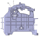
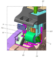
도 1은 본 발명에 따른 자동변속기 차량의 시프트 락 및 시프트 락 릴리즈를 구현하기 위한 일체형 장치가 결합된 시프트레버 장치의 측면도,
도 2는 도 1의 시프트레버 하우징의 측면도,
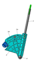
도 3은 도 1의 시프트레버를 구비한 시프트레버 바디의 측면도,
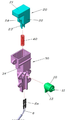
도 4는 본 발명에 따른 시프트 락 및 시프트 락 릴리즈를 구현하기 위한 일체형 장치의 분해 사시도,
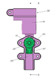
도 5는 도 4의 결합상태 사시도,
도 6과 도 7은 도 5를 A방향과 B방향에서 바라본 도면,
도 8은 도 7의 Ⅰ-Ⅰ선 단면도,
도 9는 도 6의 Ⅱ-Ⅱ선 단면도,
도 10과 도 11은 본 발명에 따른 장치에 의해서 시프트 락 기능 및 시프트 락 릴리즈 기능이 구현된 상태를 보여주기 위한 도면이다.1 is a side view of a shift lever device incorporating an integrated device for implementing a shift lock and a shift lock release of an automatic transmission vehicle according to the present invention;
Figure 2 is a side view of the shift lever housing of Figure 1,
FIG. 3 is a side view of a shift lever body having the shift lever of FIG. 1;
4 is an exploded perspective view of an integrated device for implementing a shift lock and a shift lock release according to the present invention,
FIG. 5 is a perspective view of the coupled state of FIG. 4,
Figs. 6 and 7 are views of Fig. 5 viewed from directions A and B,
8 is a sectional view taken along the line I-I in Fig. 7,
9 is a sectional view taken along a line II-II in Fig. 6,
10 and 11 are views showing a state in which the shift lock function and the shift lock release function are implemented by the apparatus according to the present invention.
이하에서는 첨부된 도면을 참조하여 본 발명의 바람직한 일실시예에 따른 자동변속기 차량의 시프트 락 및 시프트 락 릴리즈를 구현하기 위한 일체형 장치에 대해 살펴보기로 한다.Hereinafter, an integrated device for implementing a shift lock and a shift lock release of an automatic transmission vehicle according to a preferred embodiment of the present invention will be described with reference to the accompanying drawings.
도 1 내지 도 11에 도시된 바와 같이 자동변속기 차량에서 운전석 측부에는 시프트레버 하우징(1)이 차체에 고정되게 설치되고, 시프트레버 하우징(1)에는 시프트레버(2)를 구비한 시프트레버 바디(3)의 하단이 힌지축(4)을 중심으로 전후방향 회전 가능하게 결합된다.1 to 11, a
따라서, 운전자가 시프트레버(2)를 전후방향으로 조작하면 시프트레버(2)는 디텐트플레이트(5)에 형성된 레인지(range)의 홈을 따라 이동하면서 P(파킹)단, R(후진)단, N(중립)단, D(주행)단 중 어느 하나에 선택적으로 위치함에 따라 변속기의 변속단을 결정하게 된다.Accordingly, when the driver operates the
상기 시프트레버 하우징(1)의 측면에는 본 발명의 일 실시예에 따라서 시프트 락의 기능 및 시프트 락 릴리즈의 기능을 구현하기 위한 시프트 락 솔레노이드(10)와 시프트 락 릴리즈레버(20)가 1개의 케이스(30)에 의해서 일체형으로 모듈화된 일체형 장치가 고정되게 결합된다.A
즉, 본 발명에 따른 일체형 장치는 진퇴이동이 가능한 플런저(11)를 구비한 시프트 락 솔레노이드(10); 상기 시프트 락 솔레노이드(10)를 향한 이동시 플런저(11)와의 접촉으로 플런저(11)를 강제로 후퇴 이동시키는 시프트 락 릴리즈레버(20); 상기 시프트 락 솔레노이드(10)와 시프트 락 릴리즈레버(20)가 일체형으로 모듈화가 되도록 결합되는 1개의 케이스(30); 및 상기 시프트 락 릴리즈레버(20)와 케이스(30)에 양단이 지지되게 설치된 것으로 시프트 락 릴리즈레버(20)의 이동시 복귀력을 제공하는 레버스프링(40);을 포함한다.That is, the integrated device according to the present invention includes a
상기 케이스(30)는 시프트레버 하우징(1)의 일측면에 고정되게 결합되고, 상기 시프트레버 하우징(1)에는 시프트레버(2)를 구비한 시프트레버 바디(3)가 회전 가능하게 결합되며, 상기 플런저(11)의 일단은 시프트레버 하우징(1)의 구멍(1a)을 통해서 시프트레버 바디(3)와 대면하도록 설치된다.The
상기 플런저(11)는 시프트 락 솔레노이드(10)를 관통해서 양단이 시프트 락 솔레노이드(10)의 외부로 노출되도록 구성되는 바, 케이스(30)가 시프트레버 하우징(1)에 결합된 상태를 기준으로 도 8의 도시상태에서 시프트 락 솔레노이드(10)의 좌측으로 돌출된 일단은 시프트레버 하우징(1)의 구멍(1a)을 통해서 시프트레버 바디(3)와 대면하고 시프트 락 솔레노이드(10)의 우측으로 돌출된 타단은 케이스(30)내에 위치하면서 시프트 락 릴리즈레버(20)의 이동경로상에 위치하도록 구비된다.The
상기 플런저(11)는 시프트 락 솔레노이드(10)로 전원 인가시 시프트레버 바디(3)로부터 멀어지는 방향으로 후퇴 이동하고 전원 차단시 플런저스프링(12)의 탄성력으로 시프트레버 바디(2)쪽으로 전진 이동하는 동작을 하게 된다.The
운전자가 브레이크페달을 밟으면 브레이크페달 센서의 신호를 전달받은 콘트롤러(BCM)의 제어에 의해서 시프트 락 솔레노이드(10)로 전원이 인가되고, 시프트 락 솔레노이드(10)로 전원이 인가되면 자력에 의해 플런저(11)가 플런저스프링(12)의 탄성력을 이기면서 시프트레버 바디(3)로부터 멀어지는 방향으로 후퇴 이동을 하게 된다.When the driver depresses the brake pedal, power is applied to the
그리고, 운전자가 브레이크페달로부터 발을 떼면 콘트롤러(BCM)의 제어에 의해서 시프트 락 솔레노이드(10)로 인가되던 전원이 차단되고, 전원이 차단되면 솔레노이드의 자력이 소멸됨에 따라 플런저(11)는 플런저스프링(12)의 탄성력에 의해서 시프트레버 바디(2)쪽으로 전진 이동하는 동작을 하게 된다.When the driver releases his / her foot from the brake pedal, the power applied to the
시프트 락 솔레노이드(10)로 전원을 인가하기 위해 시프트 락 솔레노이드(10)에는 솔레노이드 단자(13)가 일체로 구비되고, 상기 솔레노이드 단자(13)는 전원선(6)의 단자(6a)와 전기적으로 연결된다.The
상기 시프트레버 바디(3)에는 플런저삽입홈(3a,3b)이 형성되고, 상기 플런저삽입홈(3a,3b)에 플런저(11)의 일단이 삽입되면 시프트 락 기능이 구현된다.
즉, 시프트 락 솔레노이드(10)로 전원이 차단됨에 따라 플런저(11)가 플런저스프링(12)의 탄성력에 의해서 시프트레버 바디(2)쪽으로 전진 이동하고, 이의 동작에 의해 도 10과 같이 플런저(11)의 일단이 시프트레버 하우징(1)의 구멍(1a)을 관통한 후 시프트레버 바디(3)에 형성된 플런저삽입홈(3a,3b)에 삽입되면 시프트레버(2)의 조작이 불가능한 상태 다시 말해서 시프트 락의 기능이 구현되는 것이다.10, the
도 3에서 시프트레버(2)로부터 근접거리에 형성된 플런저삽입홈(3a)은 P단 시프트 락을 구현하기 위한 홈이고, 좌측방향으로 이격된 타원형의 플런저삽입홈(3b)은 R단 시프트 락을 구현하기 위한 홈으로, 상기 타원형의 플런저삽입홈(3b)에서 플런저(11)가 우측 끝에 위치해서 걸려지면 R단 시프트 락이 구현된다.3, the
상기 플런저(11)의 타단에는 플런저(11)보다 직경이 큰 플런저플레이트(14)가 결합되고, 상기 시프트 락 릴리즈레버(20)가 레버스프링(40)의 탄성력을 이기면서 시프트 락 솔레노이드(10)를 향해서 이동할 때에 도 11과 같이 시프트 락 릴리즈레버(20)는 플런저플레이트(14)와 접촉하고, 상기 시프트 락 릴리즈레버(20)와 플런저플레이트(14)의 접촉시 플런저(11)는 시프트 락 릴리즈레버(20)의 이동력을 전달받아서 시프트레버 바디(3)로부터 멀어지는 방향으로 강제 후퇴 이동하고, 상기 플러저(11)의 강제 후퇴 이동시 플러저(11)의 일단이 플런저삽입홈(3a)으로부터 빠지게 됨에 따라 시프트 락 릴리즈 기능이 구현된다.A
도 11에 도시된 도면부호 M2는 시프트 락 릴리즈레버(20)를 가압하는 공구이다.Reference numeral M2 shown in Fig. 11 is a tool for pressing the shift
시프트 락 릴리즈 기능은 플런저(11)가 플런저삽입홈(3a)에 삽입되어 있음에 따라 시프트 락의 기능이 구현되고 있는 상태에서, 솔레노이드 등의 고장으로 인해 운전자가 브레이크페달을 밟아주더라도 플런저(11)가 플런저삽입홈(3a)으로부터 빠지지 않는 상태일 때, 작업자가 시프트 락 릴리즈레버(20)를 조작해서 플런저(11)를 강제 후퇴 이동시킴에 따라 시프트 락을 수동으로 해제시켜 주는 안전기능이다.The shift lock releasing function is a function of releasing the
본 발명에 따른 일체형 장치는 케이스(30)의 세로방향 중간위치에 시프트 락 솔레노이드(10)가 결합되고, 상기 시프트 락 솔레노이드(10)의 위쪽으로 시프트 락 릴리즈레버(20)가 케이스(30)에 결합되며, 상기 시프트 락 솔레노이드(10)에는 솔레노이드 단자(13)가 일체로 구비되고, 상기 솔레노이드 단자(13)와 전원선(6)의 단자(6a)가 연결된 연결부(M1)는 시프트 락 솔레노이드(10)를 기준으로 케이스(30)의 아래쪽부위에 의해 커버링되는 구조를 갖는다.The integrated device according to the present invention is characterized in that a
즉, 본 발명에 따른 일체형 장치는 세로방향을 따라 위에서부터 시프트 락 릴리즈레버(20)와 시프트 락 솔레노이드(10) 및 솔레노이드 단자(13)와 전원선(6)의 단자(6a)가 연결된 연결부(M1)가 배치되도록 1개의 케이스(30)에 의해서 일체형으로 모듈화된 구성인 바, 이를 통해 전체적인 외형적 크기를 컴팩트하게 구성할 수 있는 장점이 있다.That is, in the integrated device according to the present invention, the shift
상기 케이스(30)는 세로방향을 따라 위에서부터 시프트 락 릴리즈레버(20)가 결합되는 상측부(31)와, 시프트 락 솔레노이드(10)가 결합된 중간부(32), 및 솔레노이드 단자(13)와 전원선(6)의 단자(6a)가 연결된 연결부(M1)를 커버링하는 하측부(33)로 구분되고, 상기 상측부(31)와 중간부(32) 및 하측부(33)가 각각 시프트레버 하우징(1)에 스크루와 같은 체결부재(7)를 매개로 고정되도록 결합된다.The
즉, 시프트 락 릴리즈레버(20)는 사용자의 조작력 및 레버스프링(40)의 탄성력에 의해서 상하로 이동하는 부품이기에 시프트 락 릴리즈레버(20)가 결합된 케이스(30)의 상측부(31)는 강한 지지력을 확보하는 것이 바람직 한 바, 이를 위해 시프트 락 릴리즈레버(20)가 결합된 케이스(30)의 상측부(31)가 체결부재(7)를 매개로 시프트레버 하우징(1)에 고정 결합되는 것이 바람직하다.That is, since the shift
그리고, 시프트 락 솔레노이드(10)는 플런저(11)의 작동시 진동이 발생하는 부품으로 진동에 의한 떨림 및 소음의 발생을 방지할 수 있도록 강한 지지력을 확보하는 것이 바람직 한 바, 이를 위해 시프트 락 솔레노이드(10)가 결합된 케이스(30)의 중간부(32)도 체결부재(7)를 매개로 시프트레버 하우징(1)에 고정 결합되는 것이 바람직하다.The
또한, 솔레노이드 단자(13)와 전원선(6)의 단자(6a)가 연결된 연결부(M1)는 외력 또는 충격이 전달되면 쉽게 전기적 연결상태가 쉽게 분리될 수 있는 바, 이를 예방하기 위해 솔레노이드 단자(13)와 전원선(6)의 단자(6a)가 연결된 연결부(M1)를 커버링하는 케이스(30)의 하측부(33)도 체결부재(7)를 매개로 시프트레버 하우징(1)에 고정 결합되는 것이 바람직하다.The connection part M1 to which the
시프트 락 릴리즈레버(20)는 시프트 락 솔레노이드(10)의 위쪽에서 상하이동이 가능하도록 케이스(30)의 상측부(31)에 결합된 것으로 작업자의 조작력을 전달받는 최상단의 조작부(21), 상기 조작부(21)의 하측으로 연장되어서 상하이동시 안내역할을 하는 중간의 몸통부(22), 및 상기 몸통부(22)의 하측으로 돌출되어서 하측으로 이동시 플런저플레이트(14)와 접촉하는 로드부(23)를 포함한다.The shift
상기 시프트 락 릴리즈레버(20)는 조작부(21)의 가로방향 단면적이 가장 크고 로드부(23)가 가장 작으며 몸통부(22)는 조작부(21)와 로드부(23)사이의 단면적을 갖도록 형성된다.The shift
상기 조작부(21)는 작업자의 조작력을 전달받는 부위로서 보다 넓은 면적으로 조작력을 전달받을 수 있도록 가장 넓은 단면적으로 형성되는 것이 바람직하고, 그 외에 몸통부(22)와 로드부(23)는 조작부(21)보다 상대적으로 작은 단면적으로 형성함으로써 시프트 락 릴리즈레버(20)의 전체적인 외형적 크기를 축소할 수 있도록 하고, 이를 통해 경량화를 도모할 수 있도록 하는 것이 바람직하다.The
한편, 케이스(30)의 상측부(31)에서 시프트 락 릴리즈레버(20)의 몸통부(22)가 삽입된 마주 대하는 두 측벽에는 상하로 연장된 슬롯홀(34)이 형성되고, 상기 슬롯홀(34)에는 몸통부(22)에 형성된 스토퍼돌기(24)가 삽입되는 바, 상기 슬롯홀(34)과 스토퍼돌기(24)는 시프트 락 릴리즈레버(20)의 상하이동을 안내함과 더불어 케이스(30)에서 시프트 락 릴리즈레버(20)의 이탈을 방지하는 역할을 한다.On the other hand, a
이상 설명한 바와 같이 본 발명에 따른 실시예는, 시프트 락의 기능 및 시프트 락 릴리즈의 기능을 구현하기 위한 시프트 락 솔레노이드(10)와 시프트 락 릴리즈레버(20)가 1개의 케이스(30)에 의해서 일체형으로 모듈화된 구성으로, 이를 통해 설치공간의 확보를 최소화할 수 있게 됨에 따라 전체적인 사이즈 축소 및 경량화를 도모할 수 있는 장점이 있고, 조립에 따른 산포를 크게 줄일 수 있게 됨에 따라 우수한 품질을 확보할 수 있는 장점이 있으며, 더 나아가 시프트 락 또는 시프트 락 릴리즈 작동시 빠른 응답속도를 확보할 수 있게 됨으로써 품질 향상을 도모할 수 있는 장점이 있다.As described above, according to the embodiment of the present invention, the
또한, 본 발명은 시프트 락 솔레노이드(10)만을 사용해서 시프트 락의 기능을 구현하고, 시프트 락 릴리즈 레버(20)가 시프트 락 솔레노이드(10)를 직접 작동시키서 시프트 락 릴리즈 기능을 구현할 수 있는 구성으로, 이를 통해 시프트 락 솔레노이드(10)와 시프트 락 릴리즈 레버(20)를 연결하는 중간부품(종래의 시프트 락 레버)의 사용을 없앨 수 있게 됨으로써 부품수 감축과 원가절감 및 중량감소를 도모할 수 있는 장점이 있고, 더 나아가 조립시간의 단축을 통해 생산성 향상을 도모할 수 있는 장점이 있다.In addition, the present invention can realize a shift lock function by using only the
본 발명은 특정한 실시예에 관련하여 도시하고 설명하였지만, 이하의 특허청구범위에 의해 제공되는 본 발명의 기술적 사상을 벗어나지 않는 한도 내에서, 본 발명이 다양하게 개량 및 변화될 수 있다는 것은 당업계에서 통상의 지식을 가진 자에게 있어서 자명할 것이다.While the present invention has been particularly shown and described with reference to specific embodiments thereof, it will be understood by those skilled in the art that various changes in form and details may be made therein without departing from the spirit and scope of the invention as defined by the following claims It will be apparent to those of ordinary skill in the art.
1 - 시프트레버 하우징 2 - 시프트레버
3- 시프트레버 바디 3a,3b - 플런저삽입홈
6 - 전원선 10 - 시프트 락 솔레노이드
11 - 플런저 20 - 시프트 락 릴리즈레버
30 - 케이스 40 - 레버스프링1 - Shift lever housing 2 - Shift lever
3-
6 - Power line 10 - Shift lock solenoid
11 - Plunger 20 - Shift lock release lever
30 - Case 40 - Lever spring
Claims (13)
상기 시프트 락 솔레노이드를 향한 이동시 플런저와의 접촉으로 플런저를 강제로 후퇴 이동시키는 시프트 락 릴리즈레버; 및
상기 시프트 락 솔레노이드와 시프트 락 릴리즈레버가 일체형으로 모듈화가 되도록 결합되는 1개의 케이스;를 포함하는 자동변속기 차량의 시프트 락 및 시프트 락 릴리즈를 구현하기 위한 일체형 장치.A shift lock solenoid having a plunger capable of moving forward and backward;
A shift lock release lever for forcibly retracting the plunger by contact with the plunger when the shift lock solenoid is moved toward the shift lock solenoid; And
And a single case in which the shift lock solenoid and the shift lock release lever are combined so as to be integrated and modularized.
상기 시프트 락 릴리즈레버와 케이스에 양단이 지지되게 설치된 것으로 시프트 락 릴리즈레버의 이동시 복귀력을 제공하는 레버스프링;을 더 포함하는 것을 특징으로 하는 자동변속기 차량의 시프트 락 및 시프트 락 릴리즈를 구현하기 위한 일체형 장치.The method according to claim 1,
And a lever spring for supporting both ends of the shift lock release lever and the case to provide a return force when the shift lock release lever is moved. Integrated device.
상기 케이스는 시프트레버 하우징에 고정되게 결합되고;
상기 시프트레버 하우징에는 시프트레버를 구비한 시프트레버 바디가 회전 가능하게 결합되며;
상기 플런저의 일단은 시프트레버 하우징을 관통해서 시프트레버 바디와 대면하도록 설치된 것을 특징으로 하는 자동변속기 차량의 시프트 락 및 시프트 락 릴리즈를 구현하기 위한 일체형 장치.The method according to claim 1,
The case being fixedly coupled to the shift lever housing;
A shift lever body having a shift lever is rotatably coupled to the shift lever housing;
Wherein the one end of the plunger is installed to face the shift lever body through the shift lever housing, and the one end of the plunger faces the shift lever body.
상기 플런저는 시프트 락 솔레노이드를 관통해서 양단이 시프트 락 솔레노이드의 외부로 노출되도록 구성된 것을 특징으로 하는 자동변속기 차량의 시프트 락 및 시프트 락 릴리즈를 구현하기 위한 일체형 장치.The method according to claim 1,
Wherein the plunger passes through a shift lock solenoid and is exposed at both ends to the outside of a shift lock solenoid.
상기 플런저의 일단은 시프트레버 하우징에 결합된 시프트레버 바디와 대면하도록 구성되고;
상기 플런저의 타단은 시프트 락 릴리즈레버의 이동경로상에 위치하도록 구성된 것을 특징으로 하는 자동변속기 차량의 시프트 락 및 시프트 락 릴리즈를 구현하기 위한 일체형 장치.The method of claim 4,
One end of the plunger being configured to face a shift lever body coupled to the shift lever housing;
And the other end of the plunger is positioned on the movement path of the shift lock release lever.
상기 플런저는 시프트 락 솔레노이드로 전원 인가시 시프트레버 바디로부터 멀어지는 방향으로 후퇴 이동하고 전원 차단시 플런저스프링의 탄성력으로 시프트레버 바디쪽으로 전진 이동하는 것을 특징으로 하는 자동변속기 차량의 시프트 락 및 시프트 락 릴리즈를 구현하기 위한 일체형 장치.The method of claim 5,
Wherein the plunger is moved backward in a direction away from the shift lever body when the power is applied to the shift lock solenoid and is moved forward toward the shift lever body by the elastic force of the plunger spring when the power is cut off. An integrated device for implementation.
상기 시프트레버 바디에는 플런저삽입홈이 형성되고;
상기 플런저삽입홈에 플런저의 일단이 삽입시 시프트 락 기능이 구현되는 것을 특징으로 하는 자동변속기 차량의 시프트 락 및 시프트 락 릴리즈를 구현하기 위한 일체형 장치.The method of claim 5,
A plunger insertion groove is formed in the shift lever body;
And a shift lock function is implemented when one end of the plunger is inserted into the plunger insertion groove. The integrated device for implementing the shift lock and the shift lock release of the automatic transmission vehicle.
상기 플런저의 타단에는 플런저보다 직경이 큰 플런저플레이트가 결합되고;
상기 시프트 락 릴리즈레버가 시프트 락 솔레노이드를 향해서 이동할 때에 플런저플레이트와 접촉하고;
상기 시프트 락 릴리즈레버와 플런저플레이트의 접촉시 플런저는 시프트 락 릴리즈레버의 이동력을 전달받아서 시프트레버 바디로부터 멀어지는 방향으로 강제 후퇴 이동하고;
상기 플러저의 강제 후퇴 이동시 시프트 락 릴리즈 기능이 구현되는 것을 특징으로 하는 자동변속기 차량의 시프트 락 및 시프트 락 릴리즈를 구현하기 위한 일체형 장치.The method of claim 5,
A plunger plate having a larger diameter than the plunger is coupled to the other end of the plunger;
The shift lock release lever contacts the plunger plate as it moves toward the shift lock solenoid;
When the shift lock release lever and the plunger plate are in contact with each other, the plunger receives the movement force of the shift lock release lever and forcibly retracts in a direction away from the shift lever body;
And a shift lock release function is implemented when the plunger is forcibly retracted. 2. The apparatus of claim 1, wherein the shift lock release function is implemented when the plunger is forcibly retracted.
상기 케이스의 세로방향 중간위치에 시프트 락 솔레노이드가 결합되고;
상기 시프트 락 솔레노이드의 위쪽으로 시프트 락 릴리즈레버가 케이스에 결합되며;
상기 시프트 락 솔레노이드에는 솔레노이드 단자가 일체로 구비되고;
상기 솔레노이드 단자와 전원선의 연결부는 시프트 락 솔레노이드를 기준으로 케이스의 아래쪽부위에 의해 커버링되는 것을 특징으로 하는 자동변속기 차량의 시프트 락 및 시프트 락 릴리즈를 구현하기 위한 일체형 장치.The method according to claim 1,
A shift lock solenoid is coupled to a longitudinally intermediate position of the case;
A shift lock release lever is coupled to the case upwardly of the shift lock solenoid;
A solenoid terminal is integrally provided in the shift lock solenoid;
Wherein the connecting portion of the solenoid terminal and the power line is covered by a lower portion of the case with reference to a shift lock solenoid.
상기 케이스는 시프트 락 릴리즈레버가 결합된 상측부와 시프트 락 솔레노이드가 결합된 중간부 및 솔레노이드 단자와 전원선의 연결부를 커버링하는 하측부가 각각 시프트레버 하우징에 고정되도록 결합된 것을 특징으로 하는 자동변속기 차량의 시프트 락 및 시프트 락 릴리즈를 구현하기 위한 일체형 장치.The method of claim 9,
Wherein the case is coupled such that an upper portion to which the shift lock release lever is coupled and an intermediate portion to which the shift lock solenoid is coupled and a lower portion that covers the connection portion of the solenoid terminal and the power line are respectively fixed to the shift lever housing. An integrated device for implementing shift lock and shift lock release.
상기 시프트 락 릴리즈레버는 시프트 락 솔레노이드의 위쪽에서 상하이동이 가능하도록 케이스에 결합된 것으로 작업자의 조작력을 전달받는 최상단의 조작부;
상기 조작부의 하측으로 연장되어서 상하이동시 안내역할을 하는 중간의 몸통부; 및
상기 몸통부의 하측으로 돌출되어서 하측으로 이동시 플런저플레이트와 접촉하는 로드부를 포함하는 것을 특징으로 하는 자동변속기 차량의 시프트 락 및 시프트 락 릴리즈를 구현하기 위한 일체형 장치.The method of claim 8,
The shift lock release lever is coupled to the case so that the shift lock release lever can move up and down from the upper side of the shift lock solenoid.
An intermediate body portion extending downward from the operation portion and serving as simultaneous upper and lower guide portions; And
And a rod portion protruding downward from the body portion and contacting the plunger plate when moved downward. The integrated device for implementing the shift lock and the shift lock release of an automatic transmission vehicle.
상기 시프트 락 릴리즈레버는 조작부의 가로방향 단면적이 가장 크고 로드부가 가장 작으며 몸통부는 조작부와 로드부사이의 단면적을 갖도록 형성된 것을 특징으로 하는 자동변속기 차량의 시프트 락 및 시프트 락 릴리즈를 구현하기 위한 일체형 장치.The method of claim 11,
Wherein the shift lock release lever has the largest cross sectional area in the lateral direction of the operating portion and the smallest load portion and the body portion is formed to have a cross sectional area of the operating portion and the rod portion. .
상기 몸통부가 삽입된 케이스의 마주 대하는 두 측벽에는 상하로 연장된 슬롯홀이 형성되고;
상기 슬롯홀에는 몸통부에 형성된 스토퍼돌기가 삽입되며;
상기 슬롯홀과 스토퍼돌기는 시프트 락 릴리즈레버의 상하이동을 안내함과 더불어 케이스에서 시프트 락 릴리즈레버의 이탈을 방지하는 것을 특징으로 하는 자동변속기 차량의 시프트 락 및 시프트 락 릴리즈를 구현하기 위한 일체형 장치.The method of claim 11,
Wherein a slot hole extending vertically is formed on two opposing side walls of the case into which the body is inserted;
A stopper projection formed in the body portion is inserted into the slot hole;
Wherein the slot hole and the stopper projection guide the up and down shift of the shift lock release lever and prevent the shift lock release lever from being released from the case. .
Priority Applications (4)
| Application Number | Priority Date | Filing Date | Title |
|---|---|---|---|
| KR1020170025027A KR102325546B1 (en) | 2017-02-24 | 2017-02-24 | United apparatus for implementing shift lock and shift lock release of automatic transmission vehicle |
| US15/825,578 US10571014B2 (en) | 2017-02-24 | 2017-11-29 | Integrated apparatus for implementing shift lock and shift lock release functions of automatic transmission vehicle |
| CN201711274052.8A CN108506479B (en) | 2017-02-24 | 2017-12-06 | Integrated device for implementing shift lock and shift lock release functions |
| DE102017222053.8A DE102017222053A1 (en) | 2017-02-24 | 2017-12-06 | INTEGRATED DEVICE FOR IMPLEMENTING A SWITCH LOCK AND SWITCH LOCK RELEASE FUNCTION OF AN AUTOMATIC TRANSMISSION FROM A VEHICLE |
Applications Claiming Priority (1)
| Application Number | Priority Date | Filing Date | Title |
|---|---|---|---|
| KR1020170025027A KR102325546B1 (en) | 2017-02-24 | 2017-02-24 | United apparatus for implementing shift lock and shift lock release of automatic transmission vehicle |
Publications (2)
| Publication Number | Publication Date |
|---|---|
| KR20180098456A true KR20180098456A (en) | 2018-09-04 |
| KR102325546B1 KR102325546B1 (en) | 2021-11-15 |
Family
ID=63112655
Family Applications (1)
| Application Number | Title | Priority Date | Filing Date |
|---|---|---|---|
| KR1020170025027A Active KR102325546B1 (en) | 2017-02-24 | 2017-02-24 | United apparatus for implementing shift lock and shift lock release of automatic transmission vehicle |
Country Status (4)
| Country | Link |
|---|---|
| US (1) | US10571014B2 (en) |
| KR (1) | KR102325546B1 (en) |
| CN (1) | CN108506479B (en) |
| DE (1) | DE102017222053A1 (en) |
Cited By (1)
| Publication number | Priority date | Publication date | Assignee | Title |
|---|---|---|---|---|
| KR102347764B1 (en) * | 2020-07-21 | 2022-01-05 | 현대자동차주식회사 | Shift lever assembly system for vehicle |
Families Citing this family (4)
| Publication number | Priority date | Publication date | Assignee | Title |
|---|---|---|---|---|
| CN109555851A (en) * | 2018-12-29 | 2019-04-02 | 宁波正朗汽车零部件有限公司 | A kind of locking structure of automatic gear shifting device |
| CN113840992B (en) * | 2019-04-10 | 2022-09-09 | 北美日产公司 | Shifter assembly, shift lock protection method, and shift lock lever |
| JP2022131692A (en) * | 2021-02-26 | 2022-09-07 | 株式会社東海理化電機製作所 | Shifter |
| JP7849977B2 (en) * | 2022-02-02 | 2026-04-22 | 株式会社Subaru | Vehicle shift lock mechanism |
Citations (4)
| Publication number | Priority date | Publication date | Assignee | Title |
|---|---|---|---|---|
| US5078242A (en) * | 1988-06-13 | 1992-01-07 | United Technologies Automotive, Inc. | Solenoid system for, for example, a brake/shift interlock for vehicular transmission control |
| US5402870A (en) * | 1993-05-18 | 1995-04-04 | Grand Haven Stamped Products, Div. Of Jsj Corporation | Vehicle park/lock mechanism |
| KR200373783Y1 (en) | 2004-10-25 | 2005-01-27 | 삼립산업 주식회사 | Shift locking device for automatic transmission |
| US20080022805A1 (en) * | 2006-07-28 | 2008-01-31 | Brian Douglas Howe | Shift lever locking mechanism |
Family Cites Families (12)
| Publication number | Priority date | Publication date | Assignee | Title |
|---|---|---|---|---|
| US4061250A (en) * | 1975-05-31 | 1977-12-06 | Tetsuya Tada | Depress button type sprayer |
| JPH071317Y2 (en) * | 1987-11-04 | 1995-01-18 | 三菱自動車工業株式会社 | Vehicle selector lever device |
| US5465818A (en) * | 1994-01-07 | 1995-11-14 | Grand Haven Stamped Products Div Of Jsj Corporation | Park lock mechanism with means to prevent lockout member from accidentially becoming inoperative |
| US5799517A (en) * | 1994-08-30 | 1998-09-01 | Kabushiki Kaisha Tokai Rika Denki Seisakusho | Vehicle locking device |
| EP1210242A4 (en) * | 1999-07-29 | 2006-01-25 | Grand Haven Stamped Products | GEARBOX WITH PARK POSITION AND POSITION POINT DEATH BLOCKED |
| US6676564B2 (en) * | 2002-01-18 | 2004-01-13 | Saia-Burgess Inc. | Brake-shift lever interlock unit |
| JP4199951B2 (en) * | 2002-03-06 | 2008-12-24 | アルプス電気株式会社 | By-wire shift lever device for vehicles |
| DE102008006398A1 (en) * | 2008-01-28 | 2009-07-30 | Zf Friedrichshafen Ag | Emergency unlocking device for parking brake |
| JP2015006866A (en) * | 2013-06-26 | 2015-01-15 | デルタ工業株式会社 | Automatic transmission shift device |
| CN103821925B (en) * | 2014-03-05 | 2016-07-13 | 十堰达峰软轴有限公司 | Electron gear shifting device |
| KR101558766B1 (en) * | 2014-05-08 | 2015-10-12 | 현대자동차주식회사 | Gear-shift lever module |
| JP6379014B2 (en) * | 2014-11-13 | 2018-08-22 | 株式会社東海理化電機製作所 | Shift device |
-
2017
- 2017-02-24 KR KR1020170025027A patent/KR102325546B1/en active Active
- 2017-11-29 US US15/825,578 patent/US10571014B2/en active Active
- 2017-12-06 DE DE102017222053.8A patent/DE102017222053A1/en not_active Withdrawn
- 2017-12-06 CN CN201711274052.8A patent/CN108506479B/en active Active
Patent Citations (4)
| Publication number | Priority date | Publication date | Assignee | Title |
|---|---|---|---|---|
| US5078242A (en) * | 1988-06-13 | 1992-01-07 | United Technologies Automotive, Inc. | Solenoid system for, for example, a brake/shift interlock for vehicular transmission control |
| US5402870A (en) * | 1993-05-18 | 1995-04-04 | Grand Haven Stamped Products, Div. Of Jsj Corporation | Vehicle park/lock mechanism |
| KR200373783Y1 (en) | 2004-10-25 | 2005-01-27 | 삼립산업 주식회사 | Shift locking device for automatic transmission |
| US20080022805A1 (en) * | 2006-07-28 | 2008-01-31 | Brian Douglas Howe | Shift lever locking mechanism |
Cited By (1)
| Publication number | Priority date | Publication date | Assignee | Title |
|---|---|---|---|---|
| KR102347764B1 (en) * | 2020-07-21 | 2022-01-05 | 현대자동차주식회사 | Shift lever assembly system for vehicle |
Also Published As
| Publication number | Publication date |
|---|---|
| CN108506479A (en) | 2018-09-07 |
| CN108506479B (en) | 2021-03-26 |
| KR102325546B1 (en) | 2021-11-15 |
| DE102017222053A1 (en) | 2018-08-30 |
| US10571014B2 (en) | 2020-02-25 |
| US20180245683A1 (en) | 2018-08-30 |
Similar Documents
| Publication | Publication Date | Title |
|---|---|---|
| KR20180098456A (en) | United apparatus for implementing shift lock and shift lock release of automatic transmission vehicle | |
| EP0315173B1 (en) | Locking apparatus for shift lever in automatic transmission | |
| US10436310B2 (en) | Activation apparatus for a transmission of a motor vehicle | |
| CN104661883B (en) | Parking brake valve signaling incomplete reaching of the parking brake position | |
| US20170114892A1 (en) | Shift lever device | |
| JP5976304B2 (en) | Parking brake locking device | |
| JP3103291B2 (en) | Vehicle lock device | |
| US9970536B2 (en) | Shift device | |
| KR20160145916A (en) | Button type electronic shift lever system | |
| JP2000272370A (en) | Shift lever unit | |
| KR100892484B1 (en) | Shift lock release device of transmission | |
| CN113236762B (en) | Key type gear shifter | |
| JP2004243927A (en) | Shift device of vehicle | |
| KR101375779B1 (en) | Shift lever assembly where locking is releasable by electronic button | |
| JP6890892B2 (en) | Shift lock mechanism of automatic transmission | |
| JP7431202B2 (en) | shift device | |
| KR100212796B1 (en) | Transmission operation device for automatic transmission of automobile | |
| JP7528859B2 (en) | Vehicle shift device | |
| JP2001171384A (en) | Shift lever device | |
| KR102347764B1 (en) | Shift lever assembly system for vehicle | |
| JP2018127105A (en) | Shift device | |
| KR100887827B1 (en) | Shift lever device of an automatic transmission for an automobile | |
| KR101619408B1 (en) | Shift lock adjustment button for vehicles | |
| JPH0744846Y2 (en) | Shift lock device for vehicle | |
| JP4630191B2 (en) | Shift lock mechanism |
Legal Events
| Date | Code | Title | Description |
|---|---|---|---|
| PA0109 | Patent application |
St.27 status event code: A-0-1-A10-A12-nap-PA0109 |
|
| R18-X000 | Changes to party contact information recorded |
St.27 status event code: A-3-3-R10-R18-oth-X000 |
|
| R18-X000 | Changes to party contact information recorded |
St.27 status event code: A-3-3-R10-R18-oth-X000 |
|
| PG1501 | Laying open of application |
St.27 status event code: A-1-1-Q10-Q12-nap-PG1501 |
|
| PN2301 | Change of applicant |
St.27 status event code: A-3-3-R10-R13-asn-PN2301 St.27 status event code: A-3-3-R10-R11-asn-PN2301 |
|
| PN2301 | Change of applicant |
St.27 status event code: A-3-3-R10-R13-asn-PN2301 St.27 status event code: A-3-3-R10-R11-asn-PN2301 |
|
| R18-X000 | Changes to party contact information recorded |
St.27 status event code: A-3-3-R10-R18-oth-X000 |
|
| R18-X000 | Changes to party contact information recorded |
St.27 status event code: A-3-3-R10-R18-oth-X000 |
|
| A201 | Request for examination | ||
| PA0201 | Request for examination |
St.27 status event code: A-1-2-D10-D11-exm-PA0201 |
|
| D13-X000 | Search requested |
St.27 status event code: A-1-2-D10-D13-srh-X000 |
|
| D14-X000 | Search report completed |
St.27 status event code: A-1-2-D10-D14-srh-X000 |
|
| E902 | Notification of reason for refusal | ||
| PE0902 | Notice of grounds for rejection |
St.27 status event code: A-1-2-D10-D21-exm-PE0902 |
|
| PN2301 | Change of applicant |
St.27 status event code: A-3-3-R10-R13-asn-PN2301 St.27 status event code: A-3-3-R10-R11-asn-PN2301 |
|
| E13-X000 | Pre-grant limitation requested |
St.27 status event code: A-2-3-E10-E13-lim-X000 |
|
| P11-X000 | Amendment of application requested |
St.27 status event code: A-2-2-P10-P11-nap-X000 |
|
| P13-X000 | Application amended |
St.27 status event code: A-2-2-P10-P13-nap-X000 |
|
| E701 | Decision to grant or registration of patent right | ||
| PE0701 | Decision of registration |
St.27 status event code: A-1-2-D10-D22-exm-PE0701 |
|
| GRNT | Written decision to grant | ||
| PR0701 | Registration of establishment |
St.27 status event code: A-2-4-F10-F11-exm-PR0701 |
|
| PR1002 | Payment of registration fee |
St.27 status event code: A-2-2-U10-U11-oth-PR1002 Fee payment year number: 1 |
|
| PG1601 | Publication of registration |
St.27 status event code: A-4-4-Q10-Q13-nap-PG1601 |
|
| PN2301 | Change of applicant |
St.27 status event code: A-5-5-R10-R13-asn-PN2301 St.27 status event code: A-5-5-R10-R11-asn-PN2301 |
|
| PR1001 | Payment of annual fee |
St.27 status event code: A-4-4-U10-U11-oth-PR1001 Fee payment year number: 4 |
|
| PR1001 | Payment of annual fee |
St.27 status event code: A-4-4-U10-U11-oth-PR1001 Fee payment year number: 5 |
|
| U11 | Full renewal or maintenance fee paid |
Free format text: ST27 STATUS EVENT CODE: A-4-4-U10-U11-OTH-PR1001 (AS PROVIDED BY THE NATIONAL OFFICE) Year of fee payment: 5 |