KR20180098422A - Footwear fluid-filled chamber having central tensile feature - Google Patents
Footwear fluid-filled chamber having central tensile feature Download PDFInfo
- Publication number
- KR20180098422A KR20180098422A KR1020187024380A KR20187024380A KR20180098422A KR 20180098422 A KR20180098422 A KR 20180098422A KR 1020187024380 A KR1020187024380 A KR 1020187024380A KR 20187024380 A KR20187024380 A KR 20187024380A KR 20180098422 A KR20180098422 A KR 20180098422A
- Authority
- KR
- South Korea
- Prior art keywords
- chamber
- forming
- fill chamber
- fluid fill
- support structure
- Prior art date
- Legal status (The legal status is an assumption and is not a legal conclusion. Google has not performed a legal analysis and makes no representation as to the accuracy of the status listed.)
- Granted
Links
Images


Classifications
-
- A—HUMAN NECESSITIES
- A43—FOOTWEAR
- A43B—CHARACTERISTIC FEATURES OF FOOTWEAR; PARTS OF FOOTWEAR
- A43B13/00—Soles; Sole-and-heel integral units
- A43B13/14—Soles; Sole-and-heel integral units characterised by the constructive form
- A43B13/18—Resilient soles
- A43B13/189—Resilient soles filled with a non-compressible fluid, e.g. gel, water
-
- A—HUMAN NECESSITIES
- A43—FOOTWEAR
- A43B—CHARACTERISTIC FEATURES OF FOOTWEAR; PARTS OF FOOTWEAR
- A43B13/00—Soles; Sole-and-heel integral units
- A43B13/14—Soles; Sole-and-heel integral units characterised by the constructive form
- A43B13/18—Resilient soles
- A43B13/20—Pneumatic soles filled with a compressible fluid, e.g. air, gas
-
- A—HUMAN NECESSITIES
- A43—FOOTWEAR
- A43B—CHARACTERISTIC FEATURES OF FOOTWEAR; PARTS OF FOOTWEAR
- A43B7/00—Footwear with health or hygienic arrangements
- A43B7/14—Footwear with health or hygienic arrangements with foot-supporting parts
- A43B7/1405—Footwear with health or hygienic arrangements with foot-supporting parts with pads or holes on one or more locations, or having an anatomical or curved form
- A43B7/1415—Footwear with health or hygienic arrangements with foot-supporting parts with pads or holes on one or more locations, or having an anatomical or curved form characterised by the location under the foot
- A43B7/144—Footwear with health or hygienic arrangements with foot-supporting parts with pads or holes on one or more locations, or having an anatomical or curved form characterised by the location under the foot situated under the heel, i.e. the calcaneus bone
-
- A—HUMAN NECESSITIES
- A43—FOOTWEAR
- A43B—CHARACTERISTIC FEATURES OF FOOTWEAR; PARTS OF FOOTWEAR
- A43B7/00—Footwear with health or hygienic arrangements
- A43B7/14—Footwear with health or hygienic arrangements with foot-supporting parts
- A43B7/1405—Footwear with health or hygienic arrangements with foot-supporting parts with pads or holes on one or more locations, or having an anatomical or curved form
- A43B7/1475—Footwear with health or hygienic arrangements with foot-supporting parts with pads or holes on one or more locations, or having an anatomical or curved form characterised by the type of support
- A43B7/148—Recesses or holes filled with supports or pads
-
- B—PERFORMING OPERATIONS; TRANSPORTING
- B33—ADDITIVE MANUFACTURING TECHNOLOGY
- B33Y—ADDITIVE MANUFACTURING, i.e. MANUFACTURING OF THREE-DIMENSIONAL [3D] OBJECTS BY ADDITIVE DEPOSITION, ADDITIVE AGGLOMERATION OR ADDITIVE LAYERING, e.g. BY 3D PRINTING, STEREOLITHOGRAPHY OR SELECTIVE LASER SINTERING
- B33Y80/00—Products made by additive manufacturing
Landscapes
- Health & Medical Sciences (AREA)
- Epidemiology (AREA)
- General Health & Medical Sciences (AREA)
- Public Health (AREA)
- Chemical & Material Sciences (AREA)
- Engineering & Computer Science (AREA)
- Manufacturing & Machinery (AREA)
- Materials Engineering (AREA)
- Footwear And Its Accessory, Manufacturing Method And Apparatuses (AREA)
Abstract
신발류 물품은 가압된 유체를 수용하고, 정상부, 저부, 및 상기 챔버의 주변부 주위의 측부들을 갖는 챔버를 포함하는 밑창 구조체를 포함한다. 밑창 구조체는 또한 챔버의 대향하는 측부들 사이의 챔버의 중심부에 위치되는 중심 구조를 포함하여, 상기 챔버는 상기 중심 구조의 주위에서 상기 중심 구조로부터 상기 챔버의 측부들까지 연장되는 주변 영역에 부가적인 구조들이 없다. 중심 구조의 모든 방향에서, 상기 중심 구조와 최근접 측부 사이의 상기 주변 영역의 치수는 대향하는 측부들 사이의 상기 챔버를 가로지르는 길이의 1/3 이상으로 된다. The footwear article includes a sole structure that contains a pressurized fluid and a chamber having a top, a bottom, and sides about the periphery of the chamber. The sole structure also includes a central structure located in a central portion of the chamber between opposite sides of the chamber such that the chamber has an additional peripheral region extending from the central structure to the sides of the chamber, There are no structures. In all directions of the central structure, the dimension of the peripheral region between the central structure and the closest side portion is at least 1/3 of the length across the chamber between the opposing side portions.
Description
종래의 운동화류 물품은 2개의 주요 구성요소, 즉 갑피(upper) 및 밑창 구조체를 포함한다. 갑피는 밑창 구조체에 대하여 발을 확실하게 수용하고 고정시키는 빈 공간을 획정하는 복수의 재료 구성요소들[예를 들어, 직물, 가죽 및 포옴(foam) 재료들]로 형성될 수 있다. 밑창 구조체는 갑피의 하면에 고정되고 일반적으로 발과 지면 간에 연장되도록 위치되어 있다. 지면반력을 약화시키는 것에 더하여, 밑창 구조체는 정지 마찰력을 제공하고, 안정성을 전달하며, 회내(廻內)와 같은 다양한 발 움직임들을 제한할 수 있다. 따라서, 갑피 및 밑창 구조체는 협조적으로 동작하여 걷기 및 달리기 등의 매우 다양한 보행 활동들에 적합한 편안한 구조를 제공한다.A conventional running shoes article includes two main components, an upper and a sole structure. The upper may be formed of a plurality of material components (e.g., fabric, leather, and foam materials) that define voids that securely receive and secure the feet against the sole structure. The sole structure is secured to the lower surface of the upper and is generally positioned to extend between the foot and the ground. In addition to weakening the ground reaction force, the sole structure can provide static traction, transmit stability, and limit various foot movements such as rotation. Thus, the upper and sole structures operate cooperatively to provide a comfortable fit for a wide variety of walking activities, such as walking and running.
운동화류 물품의 밑창 구조체는 일반적으로 안락감을 향상시키는 안창 (insole), 적어도 부분적으로 폴리머 포옴 재료로 형성된 탄력성 중창(midsole), 및 내마모성 및 정지 마찰력을 제공하는 지면접촉 바깥창(outsole)을 포함하는 계층 구조를 보인다. 중창을 위한 적절한 폴리머 포옴 재료는 인가된 부하에 대하여 탄력적으로 압축되어 지면반력을 약화시키는 에틸비닐아세테이트 또는 폴리우레탄을 포함한다. 종래의 폴리머 포옴 재료는, 실질적으로 가스로 대체되는 내부 볼륨을 정의하는 복수의 개방 또는 폐쇄된 셀들을 포함하는 것에 기인하여, 부분적으로 탄력적으로 압축된다. 반복된 압축 후에는 폴리머 포옴 셀들이 열화하여, 밑창 구조체의 압축성 감소 및 힘을 약화시키는 특성의 감소를 야기시킬 수 있다.A sole structure of a running shoes article generally includes an insole enhancing comfort, a resilient midsole formed at least partially of a polymer foam material, and a ground contacting outsole providing abrasion and static frictional forces It looks hierarchical. Suitable polymer foam materials for the midsole include ethyl vinyl acetate or polyurethane that weakens the reaction force when elastically compressed against an applied load. Conventional polymer foam materials are partially and resiliently compressed due to the fact that they contain a plurality of open or closed cells that define an internal volume that is substantially replaced by a gas. After repeated compression, the polymer foam cells may deteriorate resulting in reduced compressibility of the sole structure and reduced properties that weaken the force.
폴리머 포옴 중창의 매스(mass)를 감소시키고 반복된 압축에 따른 열화의 효과를 감소시키는 방식 중 하나는 유체충전(fluid-filled) 챔버를 중창에 포함시키는 것이다. 일반적으로, 유체충전 챔버들은 가압될 수 있는 밀봉된 탄성중합체 폴리머 재료로 형성된다. 그 후, 챔버들이 중창의 폴리머 포옴 내에 캡슐화되어 챔버와 캡슐화 폴리머 포옴의 조합이 중창으로서 기능한다. 일부 구성들에서는, 직물 또는 포옴 인장 부재들이 챔버 내에 위치되거나 또는 보강 구조들이 챔버의 외측면에 접합되어 챔버의 형상을 만들거나 챔버의 의도된 형상을 유지할 수 있다.One way to reduce the mass of the polymer foam midsole and reduce the effect of deterioration due to repeated compression is to include a fluid-filled chamber in the midsole. Generally, the fluid fill chambers are formed of a sealed elastomeric polymer material that can be pressurized. The chambers are then encapsulated in a polymer foam of the midsole such that the combination of the chamber and the encapsulating polymer foam functions as a midsole. In some arrangements, fabric or foam tension members may be positioned within the chamber or the reinforcing structures may be bonded to the outer surface of the chamber to shape the chamber or maintain the intended shape of the chamber.
신발류 용례에 적절한 유체충전 챔버들은, 탄성중합체막의 2개의 별개의 시트들이 형성되어 챔버의 전체적인 주변부 형상을 보이는 이중막 기술(two-film technique)에 의해 제조될 수 있다. 그 후, 시트들은 각각의 주변부를 따라 함께 접합되어 밀봉된 구조를 형성하고, 시트들은 또한 미리 정해진 내부 영역들에서 함께 접합되어 원하는 구성을 챔버에 제공한다. 즉, 내측 접합들(즉, 주변부로부터 내측으로 이격된 접합들)은 가압시 미리 정해진 형상 및 사이즈를 챔버에 제공한다. 챔버를 가압하기 위하여, 유체 압력원에 연결된 바늘 또는 노즐이 챔버 내에 형성된 충전 주입구(fill inlet) 내에 삽입된다. 챔버의 가압에 후속하여, 충전 주입구가 밀봉되고 노즐이 제거된다. 열성형(thermoforming)으로 호칭하는 유사한 절차도 이용될 수 있는데, 이 절차에서는 제조 공정 동안 가열된 몰드가 탄성중합체막의 시트들을 형성 또는 성형한다.Fluid filling chambers suitable for footwear use can be made by a two-film technique in which two separate sheets of an elastomeric membrane are formed to show the overall peripheral shape of the chamber. The sheets are then joined together along their respective peripheries to form a sealed structure, and the sheets are also bonded together in predetermined internal areas to provide the desired configuration to the chamber. That is, the inner joints (i.e., the inwardly spaced joints from the periphery) provide a predetermined shape and size to the chamber upon pressurization. To pressurize the chamber, a needle or nozzle connected to a fluid pressure source is inserted into the fill inlet formed in the chamber. Following the pressurization of the chamber, the filling inlet is sealed and the nozzle is removed. A similar procedure, also referred to as thermoforming, may be used in which a heated mold forms or shapes sheets of an elastomeric film during the manufacturing process.
챔버들은 또한, 튜브 형상의 용융 또는 연화된 탄성중합체 재료가 챔버의 원하는 전체적인 형상 및 구성을 갖는 몰드 내에 배치되는 블로우몰딩(blow-molding) 기술에 의해 제조될 수 있다. 몰드는 일 위치에 개구를 가지며, 이 개구를 통하여 가압된 공기가 제공된다. 가압된 공기는 액화된 탄성중합체 재료가 몰드의 내측 표면들의 형상을 따르도록 유도한다. 그 후, 탄성중합체 재료는 냉각되어, 원하는 형상 및 구성의 챔버를 형성한다. 이중막 기술과 같이, 챔버를 가압하기 위하여, 유체 압력원에 연결된 바늘 또는 노즐이 챔버에 형성된 충전 주입구 내로 삽입된다. 챔버의 가압에 후속하여, 충전 주입구가 밀봉되고 노즐이 제거된다.The chambers may also be manufactured by blow-molding techniques in which a tube-shaped molten or softened elastomeric material is placed in a mold having the desired overall shape and configuration of the chamber. The mold has an opening in one position, and the pressurized air is provided through the opening. The pressurized air induces the liquefied elastomeric material to follow the shape of the inner surfaces of the mold. The elastomeric material is then cooled to form a chamber of the desired shape and configuration. As with the double membrane technique, a needle or nozzle connected to a source of fluid pressure is inserted into a fill inlet formed in the chamber to pressurize the chamber. Following the pressurization of the chamber, the filling inlet is sealed and the nozzle is removed.
신발류 물품은 갑피 및 갑피에 고정된 밑창 구조체를 가질 수 있다. 밑창 구조체는, 가압된 유체를 수용하기 위한 내부 빈 공간을 획정하는 챔버를 포함할 수 있으며, 상기 챔버는 정상부, 저부, 및 챔버의 주변부 주위의 정상부와 저부 사이에 연장되는 측부들을 포함한다. 또한, 밑창 구조체는 챔버의 대향하는 측부들 사이의 챔버의 중심부에 위치한 중심 구조를 포함하여, 챔버는 중심 구조의 주위의 주변 영역에 중심 구조로부터 챔버의 측부들까지 연장되는 부가적인 구조들이 없을 수 있다. 또한, 중심 구조의 모든 측면에서 중심 구조와 최근접 측부 사이의 주변 영역의 치수는 대향하는 측부들 사이의 챔버를 가로지르는 길이의 1/3 이상이다.The footwear article may have a sole structure fixed to the upper and upper. The sole structure may include a chamber defining an interior hollow space for receiving pressurized fluid, the chamber including a top, a bottom, and sides extending between a top and a bottom around the periphery of the chamber. The sole structure also includes a central structure located in the center of the chamber between opposing sides of the chamber such that the chamber has no additional structures extending from the center structure to the sides of the chamber in a peripheral region around the central structure have. Also, in all aspects of the central structure, the dimensions of the peripheral region between the central structure and the nearest side are more than one third of the length across the chamber between opposing sides.
신발류 물품은 갑피 및 갑피에 고정된 밑창 구조체를 가질 수 있다. 밑창 구조체는, 가압된 유체를 수용하기 위한 내부 빈 공간을 획정하는 챔버를 포함할 수 있으며, 상기 챔버는 실질적으로 투명한 재료로 형성되고 정상부, 저부, 및 챔버의 주변부 주위의 정상부와 저부 사이에서 연장되는 측부들을 포함한다. 또한, 밑창 구조체는, 횡방향 및 종방향에서 챔버의 중심부에 위치되고 횡방향 및 종방향에서 챔버의 대향하는 측부들 사이의 거리의 1/3 이하를 점유하는 중심 구조를 포함할 수 있다.The footwear article may have a sole structure fixed to the upper and upper. The sole structure may include a chamber defining an interior hollow space for receiving pressurized fluid, the chamber being formed of a substantially transparent material and extending between the top and bottom portions around the top, bottom, and periphery of the chamber Respectively. The sole structure may also include a centering structure located in the center of the chamber in the lateral and longitudinal directions and occupying less than one-third of the distance between the opposing sides of the chamber in the lateral and longitudinal directions.
신발류 물품은 갑피 및 갑피에 고정된 밑창 구조체를 가질 수 있다. 밑창 구조체는 가압된 유체를 수용하기 위한 내부 빈 공간을 획정하는 챔버를 포함할 수 있으며, 상기 챔버는 정상부, 저부, 및 챔버의 주변부 주위의 정상부와 저부 사이에서 연장되는 측부들을 포함한다. 또한, 밑창 구조체는, 챔버의 정상부와 챔버의 저부 사이에서 연장되어 상기 정상부와 상기 저부를 연결하는 인장 부재를 포함하는 중심 구조를 포함할 수 있다. 중심 구조는 횡방향 및 종방향에서 챔버의 중심부에 위치될 수 있으며, 횡방향 및 종방향에서 챔버의 대향하는 측부들 사이의 거리의 1/3 이하를 점유할 수 있다. 또한, 중심 구조는 접촉 영역 내에서 챔버의 정상부에 부착될 수 있으며, 챔버의 정상부는 챔버의 정상부의 다른 부분들보다 아래 방향으로 더 연장되어 챔버의 정상부에 리세스를 형성하는 접촉 영역을 포함한다. 또한, 밑창 구조체는 보강 부재를 포함하고, 보강 부재는 챔버의 정상부에 접합된 하면을 갖는 상부와, 상기 하면으로부터 아래 방향으로 챔버의 정상부의 리세스 내로 연장되는 지지 구조를 포함할 수 있다.The footwear article may have a sole structure fixed to the upper and upper. The sole structure may include a chamber defining an interior void space for receiving pressurized fluid, the chamber including a top, a bottom, and sides extending between a top and a bottom around the periphery of the chamber. The sole structure may also include a central structure including a tension member extending between the top of the chamber and the bottom of the chamber and connecting the top and bottom. The central structure may be located in the center of the chamber in the transverse and longitudinal directions and may occupy less than one-third of the distance between the opposing sides of the chamber in the transverse and longitudinal directions. The central structure may also be attached to the top of the chamber within the contact area and the top of the chamber includes a contact area that extends further downward than other parts of the top of the chamber and forms a recess in the top of the chamber . The sole structure may also include a reinforcement member, which may include a support structure extending from the top with the bottom surface bonded to the top of the chamber and into the recess of the top of the chamber downwardly from the bottom surface.
신발류 물품은 갑피 및 갑피에 고정된 밑창 구조체를 가질 수 있다. 밑창 구조체는 가압된 유체를 수용하기 위한 내부 빈 공간을 획정하는 챔버를 포함할 수 있으며, 상기 챔버는 정상부, 저부, 및 챔버의 주변부 주위에서 정상부와 저부 간에 연장되는 측부들을 포함한다. 또한, 밑창 구조체는 챔버의 대향하는 측부들 사이의 챔버의 중심부에 위치된 중심 구조를 포함하여, 챔버는 중심 구조의 주위의 주변 영역에 중심 구조로부터 챔버의 측부들까지 연장되는 부가적인 구조들이 없을 수 있다. 또한, 밑창 구조체는 아래 방향으로 챔버의 정상부의 리세스 내로 연장되어 실질적으로 리세스를 채우는 포옴 기둥(foam pillar)을 포함할 수 있다.The footwear article may have a sole structure fixed to the upper and upper. The sole structure may include a chamber defining an interior hollow space for receiving pressurized fluid, the chamber including a top, a bottom, and sides extending between the top and bottom around the periphery of the chamber. The sole structure also includes a central structure located in the center of the chamber between opposite sides of the chamber such that the chamber has no additional structures extending from the center structure to the sides of the chamber in the peripheral region around the central structure . The sole structure may also include a foam pillar extending downwardly into the recess of the top of the chamber to substantially fill the recess.
신발류 물품용 밑창 구조체를 제조하는 방법은 예비 성형된 보강 부재를 몰드의 제1 절반부 내에 삽입하는 단계, 예비 성형된 바깥창을 몰드의 제2 절반부 내에 삽입하는 단계, 및 블래더 재료(bladder material)에 대하여 몰드의 제1 절반부와 제2 절반부를 폐쇄하는 단계를 포함할 수 있다. 또한, 상기 방법은, 가압된 유체를 수용하기 위한 내부 빈 공간을 획정하는 챔버 형태로 블래더 재료를 형성하는 동시에 챔버를 보강 부재 및 바깥창에 연결하도록 열 및 압력을 가하는 단계를 포함할 수 있다. 보강 부재 및 블래더 재료 중 적어도 하나는 중심 구조를 포함한다. 열 및 압력을 가하는 단계는 중심 구조로 챔버의 정상부와 저부를 연결하는 단계를 포함할 수 있다. 또한 중심 구조로 챔버의 정상부와 저부를 연결하는 단계는, 횡방향 및 종방향에서, 챔버의 대향하는 측부들 사이의 챔버의 중심부에 중심 구조를 위치시켜, 챔버는 중심 구조의 주위의 주변 영역에 중심 구조로부터 챔버의 측부들까지 연장되는 부가적인 구조들이 없고, 중심 구조는 횡방향 및 종방향에서 챔버의 대향하는 측부들 사이의 거리의 1/3 이하를 점유할 수 있다.A method of making a sole structure for a footwear article includes the steps of inserting a preformed reinforcing member into the first half of the mold, inserting the preformed outsole into the second half of the mold, and closing the first and second halves of the mold with respect to the material. The method may also include the step of forming a bladder material in the form of a chamber defining an internal void space for receiving the pressurized fluid and simultaneously applying heat and pressure to connect the chamber to the stiffening member and the outsole . At least one of the stiffening member and the bladder material comprises a central structure. The step of applying heat and pressure may comprise coupling the top and bottom of the chamber to a central structure. The step of connecting the top and bottom of the chamber to the central structure also includes positioning the central structure in the center of the chamber between the opposing sides of the chamber in the transverse and longitudinal directions, There are no additional structures extending from the central structure to the sides of the chamber, and the central structure can occupy less than one-third of the distance between the opposing sides of the chamber in the transverse and longitudinal directions.
본 발명의 신규성이 있는 측면들의 장점들 및 특징들은 청구범위에 구체적으로 기재되어 있다. 그러나, 신규성의 장점들 및 특징들을 더 잘 이해하기 위해, 본 발명과 관련된 다양한 실시예들 및 개념들을 설명하고 예시하는 이하의 설명 및 첨부 도면들을 참조할 수 있다.The advantages and features of the novel aspects of the invention are set forth in the claims. However, for a better understanding of the novelty advantages and features, reference is made to the following description and accompanying drawings, which illustrate and exemplify various embodiments and concepts related to the present invention.
이전의 개요 및 이하의 상세한 설명은 첨부 도면들과 연계하여 읽어보면 더 잘 이해될 것이다.
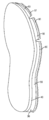
도 1은 챔버를 포함하는 밑창 구조체를 갖는 신발류 물품의 측면.
도 2는 도 1의 신발류 물품의 밑창 구조체의 챔버 구성요소의 투시도.
도 3은 도 2의 3-3선을 따라 취한 도 2에 도시된 챔버의 단면도.
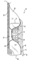
도 4는 추가적인 밑창 구조체 구성요소들을 더 도시하는 도 3에 도시된 챔버의 단면도.
도 5a는 복수의 챔버들을 포함하는 전체 길이 밑창 구조체의 측면도.
도 5b는 도 5a에 도시된 전체 길이 밑창 구조체의 저부 투시도.
도 6a는 도 5a 및 도 5b에 도시된 밑창 구조체를 조립하기 위한 몰드의 2개의 절반부들을 도시하는 도면.
도 6b는 도 6a에 도시된 몰드의 2개의 절반부들이 합쳐진 것을 도시하는 도면.
도 6c는 도 5a 및 도 5b의 밑창 구조체의 구성요소들이 도 6a의 몰드 내로 삽입되는 것을 도시하는 도면.
도 6d는 도 6a의 몰드 내에서 성형되고 접합된 밑창 구조체 구성요소들의 최종 어셈블리를 도시하는 도면.
도 7은 챔버를 포함하는 다른 밑창 구조체의 측면도.
도 8은 챔버를 포함하는 다른 밑창 구조체의 측면도.
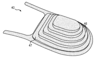
도 9는 도 8에 도시된 밑창 구조체의 보강 부재의 투시도.
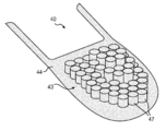
도 10은 밑창 구조체에 사용하기 위한 다른 보강 부재의 투시도.
도 11은 챔버를 포함하는 다른 밑창 구조체의 측면도.
도 12는 도 11의 12-12선을 따라 취한 도 11에 도시된 밑창 구조체의 단면도.
도 13은 챔버를 포함하는 다른 밑창 구조체 구성을 갖는 신발류 물품의 측면도.
도 14는 도 13의 신발류 물품의 밑창 구조체의 챔버 구성요소의 투시도.
도 15는 도 14에 도시된 챔버의 측면도.
도 16은 도 13에 도시된 신발류 물품의 밑창 구조체의 일 부분의 측면도.
도 17은 신발류 물품의 밑창 구조체에 사용하기 위한 다른 예시적인 챔버의 투시도.
도 18은 도 17에 도시된 챔버의 단면도.
도 19는 도 18에 도시된 챔버의 단면도로서, 챔버의 정상부 패널이 아래 방향으로 편향된 위치에 있는 것을 도시하는 단면도.
도 20은 신발류 물품을 위한 다른 밑창 구조체 구성의 측면도.The foregoing summary and the following detailed description will be better understood when read in conjunction with the accompanying drawings.
Figure 1 is a side view of an article of footwear having a sole structure comprising a chamber.
Figure 2 is a perspective view of the chamber components of the sole structure of the footwear article of Figure 1;
Figure 3 is a cross-sectional view of the chamber shown in Figure 2 taken along line 3-3 of Figure 2;
Figure 4 is a cross-sectional view of the chamber shown in Figure 3 further illustrating additional sole structure components.
Figure 5a is a side view of a full length sole structure comprising a plurality of chambers.
Figure 5b is a bottom perspective view of the full length sole structure shown in Figure 5a.
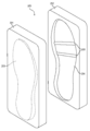
Figure 6a shows two halves of the mold for assembling the sole structure shown in Figures 5a and 5b.
Fig. 6B shows the two halves of the mold shown in Fig. 6A combined. Fig.
Fig. 6c shows that the components of the sole structure of Figs. 5a and 5b are inserted into the mold of Fig. 6a. Fig.
Figure 6d shows a final assembly of the sole structure components molded and bonded in the mold of Figure 6a.
7 is a side view of another sole structure including a chamber;
8 is a side view of another sole structure including a chamber.
9 is a perspective view of the reinforcing member of the sole structure shown in Fig.
10 is a perspective view of another reinforcing member for use in a sole structure.
11 is a side view of another sole structure including a chamber.
12 is a cross-sectional view of the sole structure shown in Fig. 11 taken along line 12-12 of Fig. 11. Fig.
Figure 13 is a side view of an article of footwear having another sole structure configuration including a chamber.
14 is a perspective view of a chamber component of the sole structure of the footwear article of FIG.
Figure 15 is a side view of the chamber shown in Figure 14;
Figure 16 is a side view of a portion of the sole structure of the footwear article shown in Figure 13;
17 is a perspective view of another exemplary chamber for use in a sole structure of a footwear article.
Figure 18 is a cross-sectional view of the chamber shown in Figure 17;
Fig. 19 is a cross-sectional view of the chamber shown in Fig. 18, showing a top panel of the chamber in a downwardly deflected position; Fig.
Figure 20 is a side view of another sole structure construction for a footwear article.
이하의 설명 및 첨부 도면들은 챔버들 및 다른 구성요소들을 포함하는 신발류 밑창 구조체들의 다양한 구성들을 개시한다. 밑창 구조체들은 임의의 보행 활동에 적합한 구성을 갖는 신발류를 참조하여 개시된다. 개시된 밑창 구조체 구성들은 첨부 도면들에서 농구화 및 러닝 또는 일반적인 트레이닝화에서 구현되는 것으로 도시된다. 개시된 밑창 구조체들과 관련된 개념들은 농구, 러닝, 또는 일반적인 운동 트레이닝화 용으로 디자인된 신발류에 한정되는 것은 아니며, 예를 들어 테니스화, 풋볼화, 크로스트레이닝화, 워킹화 및 축구화를 포함하는 다양한 범위의 운동 신발류 스타일들에 대하여 이용될 수 있다. 밑창 구조체들과 연관된 개념들은 드레스 슈즈, 로퍼(loafer), 샌들 및 부츠를 포함하는 일반적으로 비운동적인 것으로 여겨지는 신발류 스타일들에 대하여도 이용될 수 있다. 따라서, 본 명세서에 개시된 개념들은 다양한 신발류 물품들에 적용된다.The following description and the annexed drawings disclose various configurations of footwear sole structures including chambers and other components. Sole structures are described with reference to footwear having a configuration suitable for any walking activity. The disclosed sole structure configurations are shown to be implemented in basketball and running or general training, in the accompanying drawings. The concepts associated with the disclosed sole structures are not limited to footwear designed for basketball, running, or general athletic training, but may be applied to a wide range of athletic footwear including tennis shoes, football shoes, cross-training shoes, walking shoes, Styles. ≪ / RTI > The concepts associated with sole structures can also be used for footwear styles that are generally considered non-kinetic, including dress shoes, loafer, sandals, and boots. Accordingly, the concepts disclosed herein apply to various footwear articles.
일관성 및 편의성을 위해, 예시된 구성들에 대응하는 상세한 설명에서는 방향 형용사들이 이용된다. 상세한 설명 및 청구범위에 걸쳐 이용된 용어 "종방향"은 밑창 구조체의 길이를 연장하는 방향, 즉 밑창의 전족부로부터 힐부로 연장되는 방향을 의미한다. 용어 "전방"은 발의 발가락들이 가리키는 일반적인 방향을 나타내기 위해 이용되고, 용어 "후방"은 그 반대 방향, 즉 발의 뒤꿈치가 향하고 있는 방향을 나타내기 위해 이용된다.For consistency and convenience, directional adjectives are used in the detailed description corresponding to the illustrated configurations. The term "longitudinal " as used throughout the description and claims means the direction extending the length of the sole structure, i.e. the direction extending from the forefoot of the sole to the heel. The term " front "is used to denote the general direction in which the toes of the foot are pointed, and the term" rear "is used to indicate the opposite direction, i.e., the direction in which the heel of the foot is pointing.
상세한 설명 및 청구범위에 걸쳐 사용된 용어 "횡방향(lateral direction)"은 밑창의 폭을 연장하는 측-대-측(side-to-side) 방향을 나타낸다. 즉, 횡방향은 신발류 물품의 안쪽 측부(medial side)와 바깥쪽 측부(lateral side) 사이에서 연장될 수 있으며, 신발류 물품의 바깥쪽 측부는 다른 발로부터 멀어지는 쪽을 향하는 표면이고, 안쪽 측부는 다른 발 쪽을 향하는 표면이다.The term "lateral direction " used throughout the description and claims refers to a side-to-side direction that extends the width of the sole. That is, the transverse direction may extend between the medial side and the lateral side of the article of footwear, the outer side of the footwear article is a surface facing away from the other foot, It is the surface facing the foot.
상세한 설명 및 청구범위에 걸쳐 사용된 용어 "수평의"는 지면과 실질적으로 평행한 임의의 방향을 나타내며, 그 사이의 종방향, 횡방향 및 모든 방향들을 포함한다. 유사하게, 상세한 설명 및 청구범위에서 사용된 용어 "측(side)"은 위쪽 방향 또는 아래 방향이 아닌, 일반적으로 횡방향, 내측 방향, 전방 및/또는 후방으로 향하는 구성요소의 임의의 부분을 나타낸다.The term "horizontal" used throughout the description and claims refers to any direction that is substantially parallel to the paper surface and includes longitudinal, transverse, and all directions therebetween. Similarly, the term "side" as used in the description and claims refers to any portion of a component that is generally transverse, inward, forward, and / or rearward rather than upward or downward .
상세한 설명 및 청구범위 전반에 걸쳐 사용된 용어 "수직의"는 일반적으로 횡방향 및 종방향에 직교하는 방향을 나타낸다. 예를 들어, 밑창이 지면 상에 평평하게 배치되어 있는 경우, 수직 방향은 지면으로부터 위쪽 방향으로 연장될 수 있다. 이 방향 형용사들의 각각은 전체로서의 신발류 물품 또는 신발류의 개별 구성요소들에 적용될 수 있다. 용어 "위쪽 방향"은 지면으로부터 멀어지는 수직 방향을 나타내는 한편, 용어 "아래 방향"은 면 쪽으로 향하는 수직 방향을 나타낸다. 유사하게, 용어들 "정상", "상부", 및 다른 유사한 용어들은 지면으로부터 수직 방향으로 실질적으로 가장 멀리 있는 물체의 부분을 나타내며, 용어들 "저부", "하부", 및 다른 유사한 용어들은 지면으로부터 수직 방향으로 실질적으로 가장 가까운 물체의 부분을 나타낸다.The term "vertical" as used throughout the description and claims generally refers to directions transverse and longitudinally orthogonal. For example, when the sole is placed flat on the ground, the vertical direction can extend upward from the ground. Each of these adjectives can be applied to the footwear article as a whole or individual components of the footwear. The term " upward direction "refers to the vertical direction away from the ground, while the term" downward direction " refers to the vertical direction toward the plane. Similarly, the terms "normal "," upper ", and other like terms refer to a portion of an object that is substantially furthest in the vertical direction from the ground and the terms "bottom," Lt; RTI ID = 0.0 > substantially < / RTI >
본 개시를 위하여, 이전의 방향 관련 용어들은, 신발류 물품과 관련하여 사용되는 경우, 밑창이 지면 쪽으로 향하면서 바로 세워져 있는 경우의 신발류 물품을 나타내며, 즉 실질적으로 수평면 상에 서 있는 착용자에 의해 착용되었을 경우 위치되는 바와 같다.For the purposes of this disclosure, previous directional terms, when used in connection with an article of footwear, indicate an article of footwear when the sole is pointed straight toward the ground, i.e., worn by a wearer standing on a substantially horizontal plane As shown in FIG.
또한, 본 개시를 위하여, 용어 "고정 부착된"은 2개의 구성요소들이 용이하게 분리될 수 없는 방식으로(예를 들어, 구성요소들 중 한 쪽 또는 양쪽을 파괴하지 않으면서) 연결되는 것을 나타낸다. 고정 부착의 예시적인 양상들은 영구 접착제, 리벳, 스티치, 못, 스테이플, 용접 또는 다른 열적 접합, 및/또는 다른 접합 기술들로 연결하는 것을 포함한다. 또한, 두 구성요소들은, 예를 들어 몰딩 프로세스에서, 일체로 형성되어 "고정 부착"될 수 있다.Further, for purposes of this disclosure, the term "fixedly attached" indicates that two components are connected in a manner that is not easily separable (e.g., without destroying one or both of the components) . Exemplary aspects of fixed attachment include connecting with permanent adhesives, rivets, stitches, nails, staples, welding or other thermal bonding, and / or other bonding techniques. In addition, the two components can be integrally formed and "fixedly attached" in, for example, a molding process.
일반적인 신발류 구조General footwear structure
신발류(10) 물품은 갑피(20) 및 밑창 구조체(30)를 포함하는 것으로 도 1에 도시되어 있다. 참고로, 도 1에 도시된 바와 같이, 신발류(10)는 3개의 일반적인 영역들, 즉 전족 영역(11), 중족 영역(12) 및 힐 영역(13)으로 구분될 수 있다. 또한, 신발류(10)는 바깥쪽 측부(14) 및 안쪽 측부(15)를 포함한다. 전족 영역(11)은 일반적으로 중족골(metatarsals)과 지골(phalanges)을 연결하는 관절들 및 발가락들에 대응하는 신발류(10)의 부분들을 포함한다. 중족 영역(12)은 일반적으로 발의 장심 영역(arch area)에 대응하는 신발류(10)의 부분들을 포함하며, 힐 영역(13)은 종골(calcaneus bone)을 포함하는 발의 뒷부분들에 대응한다. 바깥쪽 측부(14) 및 안쪽 측부(15)는 각각의 영역들(11 내지 13)에 걸쳐 연장되며 신발류(10)의 반대되는 측부들에 대응한다. 영역들(11 내지 13) 및 측부들(14 및 15)은 신발류(10)의 정확한 영역들을 구분하기 위한 것은 아니다. 오히려, 영역들(11 내지 13) 및 측부들(14 및 15)은 신발류(10)의 일반적인 영역들을 표현하여 이하의 설명을 돕기 위한 것이다. 신발류(10) 이외에, 영역들(11 내지 13) 및 측부들(14 및 15)은 갑피(20), 밑창 구조체(30), 및 그들의 개별 구성요소들에 적용될 수도 있다.
갑피(20)는 실질적으로 종래의 구성을 갖는 것으로 도시된다. 또한, 갑피(20)는 스티치되거나(stitched) 서로 끈끈하게 접합되어 발을 안전하고 편안하게 수용하기 위한 내부 빈 공간을 형성하는 복수의 적절한 재료 구성요소들(예를 들어, 직물들, 포옴, 가죽, 합성 가죽 및 다른 재료들) 중 어느 하나를 포함할 수 있다. 상기 재료 구성요소들은 갑피(20)에 대하여, 예를 들어 내구성, 통기성, 내마모성, 유연성 및 안락감의 특성들을 선택적으로 제공하도록 선택되어 위치될 수 있다. 본 명세서에 개시되는 갑피 및/또는 다른 신발류 구성요소들은 임의의 적절한 재료들로 형성될 수 있다. 일부 구성들에서, 개시된 신발류(10)는, 참조로 그 내용 전체가 인용되는 라이덴 등의 미국 특허 제5,709,954호에 개시된 하나 이상의 재료들을 채택할 수 있다.The upper 20 is shown as having a substantially conventional configuration. The upper 20 may also include a plurality of suitable material components (e.g., fabrics, foams, leather, etc.) that are stitched and adhesively bonded to one another to form an interior void space for securely and comfortably receiving the feet , Synthetic leather and other materials). The material components can be selected and positioned relative to the upper 20 to selectively provide, for example, the characteristics of durability, breathability, abrasion resistance, flexibility and comfort. The upper and / or other footwear components disclosed herein may be formed of any suitable materials. In some arrangements, the disclosed
힐 영역(13)의 발목 개구(ankle opening; 21)는 내부 빈 공간으로의 접근을 제공한다. 또한, 갑피(20)는 내부 빈 공간의 치수를 변형시키도록 종래의 방식으로 이용되는 레이스(22)를 포함하여, 내부 빈 공간 내에 발을 고정시키고 내부 빈 공간에 발을 진입시키고 제거하는 것을 용이하게 할 수 있다. 레이스(22)는 갑피(20)의 구멍들을 통하여 연장될 수 있고, 갑피(20)의 설포 부분(tong portion)은 내부 빈 공간과 레이스(22) 사이에서 연장될 수 있다. 본 발명의 다양한 측면들이 주로 밑창 구조체(30)와 관련되는 것을 고려하면, 갑피(20)는 위에서 설명한 일반적인 구성 또는 실질적으로 임의의 다른 종래 또는 비종래 갑피의 일반적인 구성을 보일 수 있다. 따라서, 갑피(20)의 전체적인 구조는 크게 변화할 수 있다.The
밑창 구조체(30)는 갑피(20)에 고정되고, 갑피(20)와 지면 사이에서 연장되는 구성을 갖는다. 지면반력을 약화시키는 것에 더하여(즉, 발에 대한 완충 작용 제공), 밑창 구조체(30)는 정지 마찰력을 제공하고, 안정성을 전달하며, 회내와 같은 다양한 발 움직임들을 제한할 수 있다. 이하에 상세히 설명되는 다양한 구성요소들 이외에, 밑창 구조체(30)는, 예를 들어 밑창 구조체(30)의 지면반력 약화 특성 또는 신발류(10)의 다른 성능 특성을 더 강화시키는 하나 이상의 지지 부재들, 조정기 또는 보강 구조들을 포함할 수 있다. 밑창 구조체(30)는 갑피(20)의 빈 공간 내에서 발의 발바닥(즉, 하부) 표면에 인접하여 위치되어 신발류(10)의 안락감을 향상시키는 안창 또는 깔창(sockliner)을 포함할 수도 있다.The
제1 밑창 구조체 구성First sole structure construction
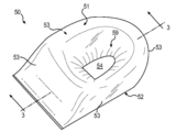
밑창 구조체(30)는, 도 1 내지 도 4에 도시된 보강 부재(40), 가압된 유체를 수용하도록 구성된 빈 공간(58)을 획정하는 챔버(50), 바깥창(60) 등의 복수의 구성요소들을 포함할 수 있다. 일부 실시예들에서, 보강 부재(40)는 밑창 구조체(30)의 상부를 형성할 수 있으며 갑피(20) 및 챔버(50)에 인접하여 고정 부착될 수 있다. 챔버(50)는 밑창 구조체(30)의 중간부를 형성하고, 보강 부재(4)와 바깥창(60) 사이에서 보강 부재(4) 및 바깥창(60)에 고정 부착된다. 또한, 바깥창(60)은 밑창 구조체(30)의 하부를 형성하고, 지면과 닿도록 위치된다.The
일부 구성들에서, 보강 부재(40), 챔버(50) 및/또는 바깥창(60)은 밑창 구조체(30)의 둘레 주위에서 연장될 수 있다. 따라서, 일부 구성들에서, 이들 구성요소들 중 하나 이상은 일반적으로 발의 윤곽과 대응하는 형상을 가질 수 있다. 이하에서 더 상세히 설명되는 바와 같이, 보강 부재(40), 챔버(50) 및/또는 바깥창(60)은 전족부(11)로부터 힐부(13)까지 연장될 수 있고, 또한 바깥쪽 측부(14)로부터 안쪽 측부(15)까지 연장될 수 있다. 그러나, 다른 구성들에서, 보강 부재(40), 챔버(50) 및/또는 바깥창(60)은 발뒤꿈치, 중족 및/또는 전족과 같은 발의 더 작은 영역에 대응하는 영역에서만 연장될 수 있다. 예를 들어, 도 1 내지 도 4에 도시된 이 구성요소들의 구성은 신발류(10)의 힐 영역(13)에 이용되도록 구성된다(도 1 참조).In some arrangements, the
일부 구성들에서, 보강 부재(40) 및/또는 챔버(50)는 신발류(10)의 외부에 노출될 수 있고, 협조하여 밑창 구조체(30)의 측면의 적어도 일 부분을 형성할 수 있다. 예를 들어, 챔버(50)의 하나 이상의 부분들이 노출될 수 있다. 일부 구성들에서, 적어도 챔버(50)의 내측부 및 외측부가 노출될 수 있다. 또한, 일부 구성들에서, 도 1에 도시되는 바와 같이, 노출되는 챔버(50)의 내측부 및 외측부 이외에, 챔버(50)의 후부(후방부)도 노출될 수 있다. 일부 구성들에서는, 챔버(50)를 형성하는 재료가 투명하게 만들어져, 챔버(50)의 중심 영역의 구조적인 특징들이 챔버(50)의 노출된 측부들을 통해 보여질 수 있다.In some arrangements, the
일부 구성들에서, 갑피(20)는 보강 부재(40)의 측부들을 따라 연장되고, 보강 부재(4)의 에지들은 밑창 구조체(30)의 측면으로부터 내부 방향으로 이격될 수 있다. 유사하게, 보강 부재(40) 및/또는 바깥창(60)의 부분들은 챔버(50)의 측부들(또는 측부들의 일부)을 커버할 수 있다. 예를 들어, 도 1에 도시된 바와 같이, 보강 부재(40)는 갑피(20)의 다른 부분 및/또는 밑창 구조체(30)의 다른 부분들에 의해 커버될 수 있다. 따라서, 보강 부재(40)의 상부면(41)은 도 1에 점선으로 나타낸다.In some arrangements the upper 20 extends along the sides of the stiffening
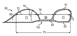
챔버(50)는 도 2 및 도 3에 개별적으로 도시되어 있다. 도 2는 챔버(50)의 투시도이고, 도 3은 도 2의 3-3선을 따라 취한 단면도이다. 챔버(50)는 블래더 재료로 형성될 수 있으며, 가압된 유체를 수용하기 위한 내부 빈 공간(58)을 획정한다. 챔버(50)는 정상부(51), 저부(52), 및 정상부(51)와 저부(52) 사이에서 연장되는 측부들(53)을 포함할 수 있다. 위에서도 설명한 바와 같이, 챔버(50)는 일반적으로 발의 바닥의 하나 이상의 부분들에 대응하는 형상을 가질 수 있다. 도 2 및 3에 도시된 챔버(50)의 구성은 일반적으로 신발류의 힐 영역 내에 포함되도록 구성된다(도 1 참조).The
일반적으로 발의 윤곽에 대응하는 형상을 갖는 것 이외에, 챔버(50)는 하나 이상의 신발류 용례들에 특히 적절한 크기 및 형상을 가질 수 있다. 예를 들어, 쿠션 작용이 가장 바람직한 성능 특성으로 되는 런닝화에서는 더 높은 (더 두꺼운) 챔버들(50)이 적절할 수 있지만, 횡방향 안정성 및 반응성을 제공하기 위해 낮은 프로파일이 적절한 농구화에서는 더 짧은 챔버들(50)이 적절할 수 있다. 또한, 챔버(50)는 테이퍼질 수 있다. 예를 들어, 도 2 및 도 3에 도시된 바와 같이, 포옴 층(foam layer) 등의 상이한 쿠션 작용 시스템을 이용할 수 있는 (연관된 유체충전 챔버 없이) 중족 및 전족 영역들과 같은 발의 다른 부분들에서 이용되는 다른 쿠션 작용 구조들로의 이동을 제공하기 위해, 챔버(50)는 전단부를 향하여 테이퍼질 수 있다.In addition to having a shape generally corresponding to the contour of the foot, the
챔버(50)는 유체를 둘러싸도록 밀봉된 배리어를 제공하는 폴리머 또는 다른 블래더 재료로 형성될 수 있다. 위에서 설명된 바와 같이, 블래더 재료는 투명할 수 있다. 챔버(50)를 위해 광범위한 폴리머 재료들이 이용될 수 있다. 챔버(50)를 위한 재료를 선택할 때, 챔버(50)에 의해 포함되는 유체의 확산을 방지하는 유체의 능력뿐만 아니라 재료의 공학 특성들(예를 들어, 인장 강도, 신축성, 피로 특성, 동적 탄성률 및 손실 탄젠트)이 고려될 수 있다. 예를 들어, 열가소성 우레탄으로 형성되는 경우, 챔버(50)의 외측 배리어(outer barrier)는 대략 1.0 ㎜의 두께를 가질 수 있지만, 두께는 예컨대 0.25 내지 2.0 ㎜ 또는 그 이상일 수 있다.The
열가소성 우레탄 이외에, 챔버(50)에 적절할 수 있는 폴리머 재료의 예들은, 폴리우레탄, 폴리에스테르, 폴리에스테르 폴리우레탄, 및 폴리에테르 폴리우레탄을 포함한다. 챔버(50)는 미첼 등의 미국특허 제5,713,141호 및 제5,952,065호에 개시된 바와 같이, 열가소성 폴리우레탄 및 에틸렌 비닐 알코올 공중합체의 교번하는 층들을 포함하는 재료로 형성될 수도 있다. 이 재료에 대한 변화도 이용될 수 있는데, 이 경우 중심층은 에틸렌 비닐 알코올 공중합체로 형성되고, 중심층에 인접한 층들은 열가소성 폴리우레탄으로 형성되며, 외측의 층들은 열가소성 폴리우레탄 및 에틸렌 비닐 알코올 공중합체의 분쇄재생 재료로 형성된다. 챔버(50)를 위한 다른 적절한 재료는, 봉크 등의 미국특허 제6,082,025호 및 제6,127,026호에 개시된 바와 같이, 가스 배리어 재료 및 열가소성 재료의 교번하는 층들을 포함하는 유연성 있는 마이크로층 멤브레인이다. 추가적인 적절한 재료는 루디의 미국특허 제4,183,156호 및 제4,219,945호에 개시되어 있다. 또한, 적절한 재료들은, 루디의 미국특허 제4,936,029호 및 제5,042,176호에 개시된 결정질 재료를 함유하는 열가소성 막들, 및 봉크 등의 미국특허 제6,013,340호, 제6,203,868호 및 제6,321,465호에 개시된 폴리에스테르 폴리올을 포함하는 폴리우레탄을 포함한다.In addition to thermoplastic urethanes, examples of polymeric materials that may be suitable for
챔버(50) 내의 유체는 압력이 0 내지 350 ㎪(즉, 제곱 인치 당 대략 51 파운드) 이상의 범위에 있을 수 있다. 밑창 구조체(30)의 일부 구성들에서, 유체에 대한 적절한 압력은 실질적으로 주변 압력일 수 있다. 즉, 유체의 압력은 신발류(10)를 둘러싸는 대기의 주변 압력의 5 ㎪ 이내일 수 있다. 챔버(50) 내의 유체의 압력은 바람직한 성능 특성들을 제공하도록 선택될 수 있다. 예를 들어, 압력이 높을수록 더욱 반응성이 좋은 쿠션 작용 구성요소를 제공할 수 있는 한편, 압력이 낮을수록 지면력을 더 약화시킬 수 있다(더 부드러운 쿠션). 챔버(50) 내의 유체의 압력은, 포옴 부재들 및/또는 인솔(비도시) 등 신발류(10)의 다른 쿠션 작용 구성요소들과 협력하여 작용하도록 선택될 수 있다.The fluid in the
일부 구성들에서, 챔버(50)는 실질적으로 순수한 질소로 팽창될 수 있다. 그러한 팽창 가스는 확산 펌핑(diffusion pumping)을 통해 챔버(50) 내의 압력의 유지를 촉진하며, 그로 인해 챔버 (50) 내의 산소 등 (질소 이외의) 다른 가스들 의 결핍은 시스템을 그러한 가스들의 챔버(50) 내로의 내향 확산으로 편향시킨다. 또한, 위에서 설명한 바와 같은 블래더 재료는 실질적으로 질소를 통과시키지 않아, 질소가 챔버(50)로부터 빠져나가는 것을 방지할 수 있다.In some configurations, the
일부 구성들에서, 챔버(50) 내의 부피 대부분을 점유하는 질소에 비교적 소량의 산소와 같은 다른 가스들 또는 공기와 같은 가스들의 혼합물이 부가될 수 있다. 공기 및 질소 이외에, 챔버(50)에 포함된 유체는 옥타플루오로프로판을 포함하거나, 예를 들어 헥사플루오로에탄 및 육불화황 등 루디의 미국특허 제4,340,626호에 개시된 가스들 중 어느 하나 일 수 있다. 일부 구성들에서, 챔버(50)는 개인이 유체의 압력을 조절할 수 있도록 해주는 밸브를 포함할 수 있다. 다른 구성들에서, 챔버(50)는, 파스케 등의 미국특허 제7,210,249호에 개시된 바와 같이, 펌프 챔버 또는 압력 챔버로서 유체 시스템 내에 포함될 수 있다. 챔버(50) 또는 챔버(50)의 부분들을 가압하기 위하여, 2012년 8월 14일자로 허여된 헨슬리 등의 미국특허 제8,241,450호 "Method For Inflating A Fluid-Filled Chamber", 및 일자로 허여된 쉰들러 등의 미국특허 제 호 "Article Of Footwear Having A Sole Structure With A Fluid-Filled Chamber"(현재 2009년 6월 18일자로 공개된 미국 특허출원 공개 US2009/0151196)에 개시된 일반적인 팽창 방법들이 이용될 수 있다. 본 단락에서 열거된 특허들 및 공개된 특허출원들은 참조에 의해 그 전체가 본 명세서에 포함된다.In some arrangements, a mixture of gases such as air or other gases such as a relatively small amount of oxygen may be added to the nitrogen occupying most of the volume within the
팽창시, 챔버들에서는 챔버를 형성하는 블래더 재료의 내측면의 모든 부분들에 균등하게 압력이 분포된다. 따라서, 팽창시, 챔버들은 외형상 둥근 형상을 취하는 경향이 있다. 그러나, 신발류의 쿠션 작용 부재들로서의 사용을 위해, 비교적 평평한 형상의 챔버들을 제공하여, 착용자의 발의 바닥을 수용하기 위한 플랫폼으로서 기능하도록 하는 것이 바람직하다. 따라서, 팽창시 챔버의 정상부 및 저부의 확장을 제한하기 위해, 하나 이상의 중심 구조들이 챔버의 정상부를 챔버의 저부에 연결할 수 있다. 예시적인 중심 구조들이 이하에 더 상세히 설명된다.At the time of expansion, pressure is evenly distributed in all parts of the inner surface of the bladder material forming the chambers in the chambers. Thus, upon swelling, the chambers tend to assume an outer rounded shape. However, for use as cushioning members of footwear, it is desirable to provide chambers of relatively flat shape to serve as a platform for receiving the floor of the wearer's foot. Thus, in order to limit the expansion of the top and bottom of the chamber upon expansion, one or more central structures may connect the top of the chamber to the bottom of the chamber. Exemplary central structures are described in greater detail below.
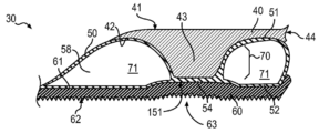
도 2 내지 도 4에 도시된 바와 같이, 리세스(59)는 밑창 구조체(30)의 중심 구조(70)의 부분일 수 있다. 도 2 및 도 3에 도시된 바와 같이, 챔버(30)의 한 섹션은, 정상부(51)가 저부(52)에 접합 또는 연결되는 접합 영역(54)을 포함할 수 있다. 접합 영역(54)은 챔버(50)의 정상부(51) 내에 리세스(59)를 형성할 수 있다.2 to 4, the
중심 구조(70)는 챔버(50)의 대향하는 측부들(53) 사이에서 챔버(50)의 중심 부분에 위치되어, 중심 구조(70) 주위의 주변 영역(71)에 중심 구조(70)로부터 챔버(50)의 측부들(53)까지 연장되는 부가적인 구조들이 없을 수 있다.The
중심 구조(70)(및 본 명세서에 개시된 다른 중심 구조들)는 챔버(50) 내에서 실질적으로 중심에 위치될 수 있다. 예를 들어, 중심 구조(70)는, 중심 구조(70)의 모든 측면에서 중심 구조(70)와 최근접 측부(53) 사이의 주변 영역(71)의 치수(72)가 대향하는 측부들(53) 사이의 챔버(50)를 가로지르는 길이(span; 73)의 1/3 이상이 되도록 챔버(50) 내에 위치될 수 있다. 일부 구성들에서, 중심 구조(70)는 횡방향 및 종방향에서 챔버(50)의 중심부에 위치될 수 있으며, 횡방향 및 종방향에서 챔버(50)의 대향하는 측부들 사이의 거리(길이; 73)의 1/3 이하인 치수(78)를 점유할 수 있다. 일부 구성들에서, 중심 구조(70)는 횡방향 및 종방향에서 챔버(50)의 중심 부분에 위치될 수 있고, 챔버(50)의 대략 1/3 이하를 점유할 수 있다. 중심 구조들에 대한 이전의 크기 및 위치 파라미터들은 일부 경우의 체적 측정, 표면적 측정, 및/또는 길이 측정에 적용될 수 있다. 일부의 경우, 접속부의 가장 큰 부분 또는 가장 작은 부분, 또는 그 사이의 임의의 부분에서 이전의 파라미터들이 취해질 수 있다. 예를 들어, 테이퍼형 중심 구조는, 예를 들어 테이퍼형 중심 구조의 가장 좁은 부분에서 챔버의 측부들로부터의 간격과 같은 위에서 설명한 파라미터들에 대하여 평가될 수 있다.The central structure 70 (and other central structures disclosed herein) may be positioned substantially centrally within the
보강 부재(40)는, 챔버(50)의 정상부(51)에 접합된 하면(42)을 포함하는 상부(44) 및 하면(42)으로부터 챔버(50)의 정상부(51) 내의 리세스(59) 내로 연장되는 지지 구조(43)를 포함할 수 있다. 지지 구조(43)는 밑창 구조체(30) 내에서 수직방향 지지를 제공할 수 있다. 지지 구조(43)는 임의의 적절한 형상을 가질 수 있다. 예를 들어, 일부 구성들에서, 지지 구조(43)는, 도 4 에 도시된 바와 같이(또한 도 1 참조), 실질적으로 절단된 원뿔형 형상을 가질 수 있다. 일부 실시예들에서, 지지 구조(43)는 기둥 형상 구성 또는 컬럼 형상(column-like) 구성을 가질 수 있다. 지지 구조(43)의 기둥 형상 또는 컬럼 형상 구성들은 임의의 적절한 형상을 가질 수 있을 것이다. 일부 구성들에서, 그러한 지지 구조들은 실질적으로 실린더형일 수 있다. 즉, 그러한 지지 구조들은 실질적으로 원형의 수평 단면 형상, 및 지지 구조의 상부로부터 지지 구조의 하부까지 실질적으로 일관된 단면 면적을 가질 수 있다. 다른 구성들에서, 그러한 지지 구조들은, 타원 형상들, 다각형 형상들, 및 불규칙 형상들을 포함하는 다른 비원형의 수평 단면 형상들을 가질 수 있다. 또한, 그러한 지지 구조들의 단면 면적은 지지 구조의 상부로부터 지지 구조의 하부에 이르기까지 변화할 수 있다.The
챔버(50)의 정상부(51)로의 보강 부재(40)의 접합은 챔버(50)의 팽출을 방지할 수 있으며, 블래더의 만곡(curvature)을 조정하여 발을 수용하기 위한 적절한 표면을 제공할 수도 있다. 예를 들어, 보강 부재(40)의 상부(44)의 하면(42)은 오목하게 되어 챔버(50)의 정상부(51)의 볼록 만곡(convex curvatures)을 수용할 수 있다. 반면, 보강 부재(40)의 상부면(41)은 비교적 평평하게 되어 있어 발을 위한 플랫폼 기능을 할 수 있다. 그러나, 핏(fit), 안락감, 및 안정성을 향상시키기 위해, 보강 부재(40)의 상부면(41)의 하나 이상의 부분들은 대응하는 발의 부분에 따라 예비 성형된 해부학적 형상을 가질 수 있다. 따라서, 상부면(41)의 힐부와 같은 일부 부분들은 착용자의 발뒤꿈치의 윤곽에 대응하는 오목 형상을 가질 수 있다. 아치부와 같은, 보강 부재(40)의 상부면(41)의 다른 부분들은 볼록 형상을 가질 수 있다.The joining of the
보강 부재(40)는 임의의 적절한 재료로 형성될 수 있다. 일부 실시예들에서, 보강 부재(40)는 플레이트로 형성될 수 있다. 그러한 플레이트는 실질적으로 비압축성일 수 있다. 또한, 일부 실시예들에서, 그러한 플레이트는 강성 또는 반강성(semi-rigid) 구성을 가질 수 있다. 적절한 플레이트는, 폴리우레탄 및/또는 비닐과 같은 강성 또는 반강성 플라스틱들, 탄소섬유 또는 다른 합성 재료들을 포함하는 임의의 적절한 재료, 또는 임의의 다른 적절한 재료로 형성될 수 있다. 그러한 예비 성형된 플레이트의 강성은, 위에서 설명한 바와 같이, 챔버(50)의 팽출을 방지할 수 있다. 또한, 그러한 플레이트는, 횡방향 및 비틀림 안정성뿐만 아니라 밑창 구조체(30)의 강도 및 지지를 제공할 수 있다.The reinforcing
일부 실시예들에서, 보강 부재(40)는, 적어도 부분적으로, 포옴 재료로 형성될 수 있다. 그러한 포옴 보강 부재는, 예를 들어, 폴리머, 폴리머 포옴, 및 다른 적절한 재료를 포함하는 다양한 범위의 재료로 제조될 수 있다. 적절한 폴리머는, 폴리에스테르, 폴리우레탄, 에틸비닐아세테이트(EVA), 열경화성 우레탄, 열가소성 우레탄, 각종 나일론 제제(nylon formulations), 고무, 폴리에테르 블록 아미드, 폴리부틸렌 테레프탈레이트 또는 이 재료들의 혼합물들을 포함한다. 예를 들어, 일부 실시예들에서, 보강 재료(40)는 폴리우레탄 포옴 또는 에틸비닐아세테이트 (EVA) 포옴으로 형성될 수 있다. 보강 재료(40)를 형성할 수 있는 부가적인 재료는, 위에서 설명한 각종 폴리머 재료에 포함된 유리 섬유들 및/또는 탄소 섬유들을 포함할 수 있는 합성 재료를 포함한다.In some embodiments, the reinforcing
또한, 일부 실시예들에서, 강성 또는 반강성 플레이트는 포옴 재료와 결합되어 보강 부재(40)를 형성할 수 있다. 예를 들어, 일부 실시예들에서, 보강 부재(40)의 상부(44)는 강성 또는 반강성 플레이트로 형성될 수 있으며 지지 구조(43)는 압축성 포옴과 같은 압축성 재료로 형성될 수 있다.Also, in some embodiments, a rigid or semi-rigid plate may be combined with a foam material to form the stiffening
일부 실시예들에서, 보강 부재(40)는 적절한 재료들의 SLS(selective laser sintering) 소립자들에 의해 형성될 수 있다. 따라서, 밑창 구조체(30)에 대하여 원하는 특성들에 따라, 보강 부재(40)를 제조시 각종 상이한 재료들이 이용될 수 있다.In some embodiments, the stiffening
도 4에 도시되는 바깥창(60)은 신발류(10)의 지면 접촉부를 형성한다. 바깥창(60)은 상부면(61) 및 반대측의 하면(62)을 갖는다. 상부면(61)은, 접착제, 용접, 스티칭, 및/또는 임의의 다른 적절한 수단과 같은 임의의 적절한 구성에 의해 챔버(50)의 저부(52)에 단단히 부착될 수 있다. 바깥창(60)을 위하여 다양한 재료들이 이용될 수 있지만, 고무 재료들이 이용되어 내구성 및 내마모성을 제공할 수 있다. 또한, 하면(62)은 신발류(10)와 지면 간에 정지 마찰력(즉, 마찰력) 특성을 제공하도록 질감이 만들어질 수 있다.The
도 4에 더 도시된 바와 같이, 일부 구성들에서, 접합 영역(54)은 챔버(50)의 저부(52)에 움푹 들어간 곳(151)을 형성할 수 있다. 챔버(50)의 정상부(51) 내의 리세스(59)는 보강 부재(40)의 아래 방향으로 연장되는 부분인 지지 구조(43)를 수용할 수 있는 반면, 챔버(50)의 저부(52) 내의 움푹 들어간 곳(151)은 포옴 재료의 대향하는 부분을 수용할 수 있거나, 도 4에 도시된 바와 같이 바깥창(60)이 움푹 들어간 챔버 재료에 직접 부착될 수 있다. 일부 구성들에서, 이것은 바깥창(60)의 저면(62)도 움푹 들어가게 할 수 있다. 다른 구성들에서, 바깥창(60)에 비교적 평평한 저면(62)을 제공하기 위해, 바깥창(60)은 움푹 들어간 곳(151)에 대응하는 영역에서 더 두껍게 만들어질 수 있다.As further shown in FIG. 4, in some arrangements, the
도 2 및 도 3은 지지 구조(43)가 챔버(50)의 외부에 배치되는 실시예를 예시하지만, 일부 실시예들에서, 지지 구조(43)는 챔버(50)의 내부에 배치될 수 있다. 예를 들어, 일부 실시예들에서, 지지 구조(43)의 상부는 챔버(50)의 정상부(51)에 연결될 수 있고, 지지 구조(43)의 저부는 챔버(50)의 저부(52)에 연결될 수 있다. 이하에 설명되는 유사한 실시예들도 챔버(50) 내부에 지지 구조를 갖고 유사하게 구성될 수 있다.Figures 2 and 3 illustrate an embodiment in which the
챔버(40) 및 보강 부재(50)는 밑창 구조체(30)의 풋베드(footbed)의 일부 또는 실질적으로 전체에 걸쳐 연장될 수 있다. 예를 들어, 도 5a는 전체 길이 밑창 구조체(30)를 예시한다. 일부 구성들에서, 챔버(50)는 신발류(10)의 전체 길이를 연장하는 단일의 빈 공간을 포함할 수 있다. 다른 구성들에서, 챔버(50)는 복수의 빈 공간들 또는 서브챔버들을 포함할 수 있다. 예를 들어, 도 5a에 도시된 바와 같이, 챔버(50)는 힐 서브챔버(55), 제1 전족 서브챔버(56) 및 제2 전족 서브챔버(57)를 포함할 수 있다. 일부 구성들에서, 서브챔버들(55, 56, 및 57)은 서로 유체 연통할 수 있다. 다른 구성들에서, 서브챔버들(55, 56, 및 57)은 도 5a에 도시된 바와 같이 3개의 독립적인 빈 공간들을 형성할 수 있다. 이 구성은 서브챔버들(55, 56, 및 57)이 상이한 압력들로 팽창되도록 할 수 있다. 따라서, 챔버(50)의 부분들은 분리되어 상이한 압력 존들을 형성하여 원하는 성능 특성을 제공할 수 있다.The
도 5a에 도시된 바와 같이, 각각의 서브챔버는 별개의 중심 구조를 포함할 수 있다. 예를 들어, 밑창 구조체(30)는 제1 중심 구조(74), 제2 중심 구조(75) 및 제3 중심 구조(76)를 포함할 수 있다. 중심 구조들(74, 75, 및 76)의 각각은 본 명세서에 설명된 구성들 중 어느 하나를 가질 수 있다. 위에서 설명된 바와 같이, 중심 구조들(74, 75, 및 76) 중 하나 이상은 실질적으로 집중화된 위치(centralized location)를 가질 수 있다.As shown in FIG. 5A, each of the sub-chambers may include a separate central structure. For example, the
또한, 도 5a에 도시된 바와 같이, 챔버(50)는 힐 영역(13)과 전족 영역(11) 사이에서 테이퍼형 구성을 보일 수 있다. 즉, 힐 영역(13)의 챔버(50)의 부분은 전족 영역(11)의 챔버(50)의 부분보다 더 큰 전체 두께를 보인다. 테이퍼링은 힐 영역(13)의 정상부(51)의 부분이 전족 영역(11)의 정상부(51)의 부분보다 일반적으로 더 큰 엘리베이션(elevation)에 있는 구성을 챔버(50)에 제공한다. 챔버(50)의 테이퍼링 및 결과적인 엘리베이션의 차이들은 발의 일반적인 해부학적 구조를 보완하는 전체적인 윤곽을 챔버(50)에 제공한다. 즉, 이 윤곽은 발의 뒤꿈치가 전족과 비교하여 약간 상승되는 것을 확실하게 해준다. 도면에 도시되어 있지는 않지만, 챔버(50)의 일부 구성들은 뒤꿈치를 수용하기 위한 힐 영역(13)의 함몰부를 포함할 수 있고, 챔버(50)는 발의 장심을 지지하는 중족 영역(12)의 돌출부를 포함할 수 있다.5A, the
도 5b는 도 5a에 도시된 전체 길이 밑창 구조체(30)의 저부 투시도를 예시한다. 도 5b에 도시된 바와 같이, 밑창 구조체(30)에 별개의 서브챔버들을 제공함으로써, 발볼(ball of the foot)에 대응하는 영역에서 밑창 구조체(30)의 해부학적 벤딩(bending)을 용이하게 할 수 있는 그루브들(77)을 형성할 수 있다.Figure 5b illustrates a bottom perspective view of the full length
밑창 구조체(30)를 제조하기 위하여 다양한 기술들이 이용될 수 있다. 일 예로서, 챔버(50)는 열성형 프로세스 동안 성형되고 접합되는 한 쌍의 폴리머 시트들로 형성될 수 있다. 구체적으로, 열성형 프로세스는, (a) 정상부(51)를 형성하기 위하여 폴리머 시트들 중 하나에 형상을 제공하고, (b) 하부(52)를 형성하기 위하여 폴리머 시트들 중 다른 하나에 형성을 제공하고, (c) 시트들 중 하나 또는 모두로부터 측부들(53)을 형성하며, (d) 정상부(51)의 내측 부분들과 챔버(50)의 저부(52)를 연결하는 접합 영역들(54)을 형성한다. 챔버(50)가 형성되면, 보강 부재(40) 및 바깥창(60)의 각각은, 예를 들어 접착제 접합 또는 열 접합을 통하여, 챔버(50)의 반대되는 측부들에 고정된다. 챔버(50)는 파리손(parison) 또는 용융된 또는 경화되지 않은(uncured) 폴리머 재료가 챔버(50)의 형상을 갖는 몰드부들 사이에서 연장되는 블로우몰딩 프로세스로 형성될 수도 있다. 그 후, 폴리머 재료는 몰드 내로 들어가서 챔버(50)의 형상을 전한다. 냉각 또는 경화 후, 챔버(50)는 몰드로부터 제거되고 보강 부재(40) 및 바깥창(60)의 각각은 챔버(50)의 반대되는 측부들에 고정된다. 밑창 구조체(30)는, 상기 열성형 및 블로우몰딩 프로세스들을 개시하는 2012년 8월 14일자 헨슬리 등의 미국특허 제8,241,450호 "Method For Inflating A Fluid-Filled Chamber", 및 일자 미국특허 제 호 "Article Of Footwear Having a Sole Structure With A Fluid-Filled Chamber" (현재는 2009년 6월 18일자 공개된 미국 특허출원 공개 US2009/0151196)에 개시된 방법들을 포함하는 임의의 적절한 방법으로 형성될 수 있다.Various techniques may be used to fabricate the
또한, 일부 경우들에서는, 일자 미국특허 제 호 "Article Of Footwear Having A Sole Structure With A Fluid-Filled Chamber" (현재는 2009년 6월 18일자 공개된 미국 특허출원 공개 US2009/0151196)에 개시된 바와 같이, 챔버(50)의 몰딩은 챔버(50)의 바깥창(60) 및 보강 부재(40)로의 연결과 동시에 수행될 수 있다. 도 6a는 도 5a 및 도 5b에 도시된 밑창 구조체(30)를 어셈블링하기 위한 몰드(200)를 예시한다. 도 6a에 도시된 바와 같이, 몰드(200)는 상부 절반부(201) 및 하부 절반부(202)를 포함할 수 있다. 상부 절반부(201)는 제1 리세스(203)를 포함할 수 있고, 하부 절반부(202)는 제2 리세스(204)를 포함할 수 있다. 도 6b는 몰드(200)의 상부 절반부(201)와 하부 절반부(202)가 합쳐진 것을 도시한다.Also, in some cases, Date US Patent As disclosed in U.S. Patent Application Publication No. US2009 / 0151196, published June 18, 2009, the molding of the
도 6c는 밑창 구조체(300)의 구성요소들이 몰드(200) 내로 삽입되는 것을 도시한다. 도 6c에 도시된 바와 같이, 몰드(200)의 하부 절반부(202)는 밑창 구조체(300)에 그루브들(77)을 형성하기 위한 리지들(205)을 포함할 수 있다(또한, 도 6a 참조). 도 6c에 도시된 바와 같이, 미리 성형된 형태의 바깥창(60)(또는 여기에서와 같이 바깥창의 조각들)이 몰드(200)의 하부 절반부(202)에 삽입될 수 있다. 유사하게, 역시 미리 성형된 형태의 보강 부재(40)[예를 들어, 포옴 지지 구조(43)를 포함]가 몰드(200)의 상부 절반부(201)에 삽입될 수 있다.6C illustrates that the components of the sole structure 300 are inserted into the
그 후, 미리 로드된 몰드 절반부들은 블래더 재료의 블랭크(155) 위에서 폐쇄될 수 있다. 도 6c에 도시된 바와 같이, 블래더 재료의 블랭크(155)는 블래더 재료의 2개의 시트들을 포함할 수 있다. 열 및 압력을 가함으로써, 블래더 재료의 블랭크(155)는 도 6d에 도시된 바와 같은 챔버(50)와 같은 챔버로 형성될 수 있다. 또한, 열 및 압력을 가함으로써 [일부 경우들에서는 몰드가 폐쇄된 상태에서 챔버(50)의 팽창을 통하여], 보강 부재(40), 챔버(50) 및 바깥창(60)이 연결될 수 있고, 챔버(50)는 성형될 수 있다. 즉, 챔버(50)는 보강 부재(40) 및 바깥창(60)과 매칭되는 형태를 갖도록 성형된다. 이 프로세스를 이용하여 형성된 예시적인 완성된 밑창 구조체 어셈블리는 도 6d에 예시된다. 일부 경우들에서, 몰딩 프로세스 동안 접착제 또는 핫 멜트가 이용되어 각종 구성요소들을 서로 접착시킬 수 있다.The preloaded mold halves can then be closed on the blank 155 of bladder material. As shown in Figure 6C, the blank 155 of bladder material may comprise two sheets of bladder material. By applying heat and pressure, the blank 155 of the bladder material can be formed into the same chamber as the
이 방법은 본 명세서에 개시된 어떠한 밑창 구조체 구성들에 대하여도 이용될 수 있다. 예를 들어, 일부 경우들에서, 중심 구조(70)는, 도 6c에 예시된 바와 같이, 보강 부재(40)의 일 부분을 형성할 수 있는 포옴 지지 구조(43)를 포함할 수 있다. 일부 경우들에서, 중심 구조는, 다른 구성들에 관하여 후술되는 바와 같이, 챔버의 정상부와 챔버의 저부 사이에 위치된 인장 부재일 수 있다.This method can be used for any sole structure configurations disclosed herein. For example, in some cases, the
성능에 관하여, 밑창 구조체(30)의 상이한 구성요소들은, 밑창 구조체(30)의 하나 이상의 영역들에서, 지지, 안정성, 지면반력의 약화(쿠션 작용), 또는 발 동작들의 제한과 같은 성능 특성들을 전한다. 포옴 기둥 구조들과 같은 중심에 위치된 지지 구조들을 갖는 구성들에서는, 신발류에 포옴 쿠션작용 구성요소들 및 유체충전 챔버의 장점들을 제공한다. 따라서, 챔버의 크기 및 두께 및/또는 챔버를 팽창시키는 가스들의 압력 및 종류뿐만 아니라, 보강 부재의 형상 및/또는 크기를 변형함으로써 그러한 신발류의 성능이 조정될 수 있다. 보강 부재(40), 챔버(50) 및 바깥창(60)의 형상 및 치수뿐만 아니라, 재료들은, 예를 들어 밑창 구조체(30)가 지면반력을 약화시키고, 안정성을 제공하며, 발의 움직임들을 제한하는 정도에 영향을 미칠 수 있다. 보강 부재(40), 챔버(50) 및 바깥창(60)의 형상, 치수, 및/또는 재료들을 변화시킴으로써, 신발류(10)의 성능 특성이 바뀔 수 있다. 즉, 신발류(10)는 보강 부재(40), 챔버(50) 및 바깥창(60) 중 하나 이상의 형상, 치수, 또는 재료들을 변형시킴으로써, 상이한 운동 활동들에 대하여 제조될 수 있다.In terms of performance, the different components of the
제1 밑창 구조체의 변형예들Modifications of the first sole structure
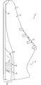
도 7에 도시된 바와 같이, 일부 구성들에서, 보강 부재(40)의 지지 구조(43)는 복수의 빈 공간들(45)을 포함할 수 있다. 예를 들어, 도 7에 도시된 바와 같이, 빈 공간들(45)은 지지 구조(43)에 절단된 원뿔형 구조를 제공한다. 지지 구조(43)의 그러한 빈 공간들은 보강 부재(40)를 가볍게 해주고/거나 지지 구조(43)를 더욱 순응적(compliant)으로 만드는 기능을 할 수 있다. 복수의 빈 공간들(45)은 보강 부재(40)의 지지 구조(43)에 허니컴 구조를 제공할 수 있다. 빈 공간들(45)은 임의의 적절한 크기 및/또는 형상을 가질 수 있다. 도 7에 도시된 바와 같이, 빈 공간들(45)은 6각형 홀들 또는 보어들일 수 있다. 또한, 지지 구조(43)는 일부 구성들에서는 속이 비어있을 수 있다. 그런 구성들에서, 빈 공간들(45)은 지지 구조(43)의 쉘에 천공부들을 형성할 수 있다. 다른 구성들에서, 지지 구조(43)는 속이 비어 있지 않아서, 빈 공간들(45)은 단순히 지지 구조(43) 내의 보어들 또는 리세스들일 수 있다. 도 7에 도시된 바와 같이, 중심 구조(70)는 하부 지지 구조(79)를 포함할 수 있다. 하부 지지 구조(79)는 저부(52)를 지지 구조(43)에 연결하는 챔버(50)의 두꺼워진 부분, 부가적인 포옴 컬럼 재료의 조각, 또는 임의의 다른 적절한 재료를 포함할 수 있다. 일부 구성들에서, 하부 지지 구조(79)는 실질적으로 비압축성일 수 있다. 다른 구성들에서, 하부 지지 구조(79)는 지지 구조(43)의 압축성과 협력하여 기능할 수 있는 어느 정도의 압축성을 가질 수 있다.7, in some configurations, the
일부 구성들에서, 바깥창(60)은, 도 7의 밑창 구조체(30)의 뒷부분에 도시된 바와 같이, 챔버(50)의 주변 에지들 주위에서 위쪽 방향으로 둘러쌀 수 있다. 중심 구조(70)를 노출하기 위하여 도 7의 바깥창(60)의 앞부분들이 단면도로 도시된다. 챔버(50)의 주변 에지들의 주위에서 위쪽 방향으로 둘러싸는 것에 의해, 바깥창(60)은 가압된 유체에 의한 팽창으로부터의 챔버(50)의 팽출을 제한하도록 더 구현될 수 있다. 이 구성은 또한 부가된 안정성 및 다른 성능 이점들을 제공할 수 있다.In some configurations, the
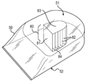
도 8 및 도 9에 도시된 바와 같이, 일부 구성들에서, 보강 부재(40)의 지지 구조(43)는 층이 진 형상(tiered shape)을 가질 수 있다. 예를 들어, 도 8에 도시된 바와 같이, 지지 구조(43)는 보강 부재(40)의 상부(44)에 인접하는 상부 스텝(47)을 포함하는 복수의 스텝들(46)을 포함할 수 있다. 그러한 구성들에서, 지지 구조(43)는 챔버(50)의 정상부(51)의 리세스 내로 아래 방향으로 연장되는 복수의 점진적으로 좁아지는 스텝들을 포함할 수 있다. 일부 구성들에서, 중심 구조(70)는, 도 8에 도시된 바와 같이, 스텝들(46)과 챔버(50)의 저부(52) 사이에 위치된 하부 지지 구조(79)를 포함할 수 있다.8 and 9, in some configurations, the
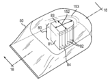
도 10은 도 8 및 도 9에 도시된 것과 유사한 다른 층이 진 지지 구조 구성을 예시한다. 도 10에 도시된 구성은 지지 구조(43)의 중심부를 향하여 점진적으로 높은 높이들을 갖는 복수의 컬럼들(47)을 구현한다. 도 10에 도시된 바와 같이, 개별 컬럼들(47)을 이용함으로써, 각각의 컬럼이 크기가 정해지고, 성형되며, 커스텀 성능 특성을 제공하는 재료로 형성될 수 있으므로, 지지 구조의 조정시 더욱 다재성(versatility)을 갖게 할 수 있다. 특히, 컬럼들(47)은 실질적으로 실린더형의 형상들, 및 비실린더형의 형상들을 포함하는 임의의 적절한 형상을 가질 수 있다. 실질적으로 실린더형의 컬럼들은 실질적으로 원형의 수평 단면 형상을 가질 수 있다. 또한, 실질적으로 실리더형의 컬럼들은 정상부로부터 저부까지 실질적으로 일관된 수평 단면 면적을 가질 수도 있다. 비실린더형의 컬럼들은 비원형 수평 단면 형상들을 가질 수 있다. 또한, 비실린더형의 컬럼들은 정상부로부터 저부까지 일관되지 않은 수평 단면 면적을 가질 수 있다.Figure 10 illustrates another layered structure similar to that shown in Figures 8 and 9; The configuration shown in FIG. 10 implements a plurality of
테이퍼지거나 층이 진 지지 구조 구성들은 부하에 대하여 점진적 컴플라이언스를 제공하도록 조정될 수 있다. 즉, 그러한 지지 구조들이 더 많이 압축될수록, 지지 구조들의 동일한 압축량을 야기시키기 위해 더 많은 부하가 요구된다. 즉, 지지 구조들은 점진적 탄성률이 제공될 수 있다.The tapered or stratified support structure configurations can be adjusted to provide gradual compliance to the load. That is, the more the support structures are compressed, the more load is required to cause the same amount of compression of the support structures. That is, the support structures may be provided with a progressive modulus of elasticity.
테이퍼형 지지 구조의 경우(도 4 내지 7 참조), 비교적 소량의 부하로 더 좁은 부분이 압축될 수 있다. 부하가 증가하고 지지 구조의 점점 더 많은 (및 점점 더 넓은) 부분들이 압축됨에 따라, 주어진 부하의 양에 대한 수직 압력의 양은 증가할 수 있다.In the case of a tapered support structure (see Figs. 4-7), a narrower portion can be compressed with a relatively small amount of load. As the load increases and the more (and increasingly wider) portions of the support structure are compressed, the amount of vertical pressure relative to the amount of load given can increase.
도 8 내지 도 10에 도시된 바와 같은 층이 진 지지 구조 구성의 경우, 비교적 소량의 부하 하에, 가장 좁은 스텝이 먼저 압축될 수 있다. 더 많고 더 넓은 스텝들이 압축됨에 따라, 동일한 양의 수직 압축을 발생시키기 위해 부하의 양을 증가시키는 것이 요구될 것이다.In the case of a layered support structure configuration as shown in Figures 8-10, under the relatively small amount of load, the narrowest step can be compressed first. As more and wider steps are compressed, it will be required to increase the amount of load to produce the same amount of vertical compression.
이 특성(점진적 탄성률)은 실질적으로 균일한 재료의 조성을 갖는 테이퍼형 (또는 계단형) 지지 구조 구성으로 제공될 수 있다. 그러나, 이 점진적 탄성률은, 층이 진 지지 구조의 상이한 스텝들에 대하여 상이한 재료들을 이용하는 것과 같이 지지 구조의 상이한 부분들에 대하여 상이한 재료들을 이용함으로써 더 증대될 수 있다. 또한, 지지 구조는 첨부도면들에 도시된 바와 같은 지지 구조의 저부 또는 정상부에서 더 좁은 부분으로 구성될 수 있다. 또한, 도 11에 도시된 구성에 관하여 후술되는 바와 같이, 모래시계 형상 또는 배럴 형상 (중간이 더 넓음) 지지 구조가 이용될 수 있다.This property (progressive modulus of elasticity) can be provided in a tapered (or stepped) support structure configuration having a composition of substantially uniform material. However, this progressive modulus can be further increased by using different materials for different parts of the support structure, such as using different materials for different steps of the layered support structure. In addition, the support structure can be composed of a narrower portion at the bottom or top of the support structure as shown in the accompanying drawings. Further, as described later with respect to the configuration shown in Fig. 11, an hourglass shape or a barrel shape (medium is wider) support structure may be used.
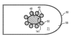
도 11 및 도 12는 다른 예시적인 지지 구조 구성을 예시한다. 도 11 및 도 12에 도시된 바와 같이, 보강 부재(40)의 지지 구조(43)는 중심 부재(48) 및 실질적으로 중심 부재(48)보다 더 작고 중심 부재(48)의 주위에서 중심 부재(48)에 인접하여 배치되는 복수의 주변 부재들(49)을 포함할 수 있다. 일부 구성들에서, 중심 부재(48)는 실린더형일 수 있는 반면, 다른 구성들에서, 중심 부재(48)는 도 12에 도시된 바와 같이 타원화된 단면 형상을 가질 수 있다. 일부 구성들에서, 도 12에 도시된 바와 같이, 복수의 실질적으로 실린더형인 주변 부재들(49)이 복수의 연결 부재들(141)을 통하여 중심 부재(48)에 부착될 수 있다. 도 12에 도시된 바와 같이, 주변 부재들(49) 중 하나 이상은 절단된 원뿔형 하부(142) 및 반전된 절단된 원뿔형 상부(143)를 갖고, 제1 직경을 갖는 정상부 및 저부와 더 좁은 제2 직경을 갖는 허리 부분(144)을 형성할 수 있다.Figures 11 and 12 illustrate other exemplary support structure configurations. 11 and 12, the
제2 밑창 구조체 구성Second sole structure construction
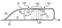
도 13은 유체충전 챔버(50)를 구현하는 다른 밑창 구조체(30)를 포함하는 신발류(10)의 물품을 예시한다. 도 13에 도시된 바와 같이, 신발류(10)는 중심 구조(80)를 포함할 수 있다. 도 14 내지 도 16에 도시된 바와 같이, 중심 구조(80)는 챔버(50)의 정상부(51)와 챔버(50)의 저부(52) 사이에서 연장되는 인장 부재(81)를 포함할 수 있다.FIG. 13 illustrates an article of
인장 부재(81)는, 팽창시, 챔버(50)의 정상부(51)와 저부(52) 사이의 거리를 제한하는 데에 적절한 임의의 구성을 가질 수 있다. 예를 들어, 인장 부재(81)는, 참조로 그 전체 내용이 본 명세서에 인용되는, 페이튼 등의 일자 미국특허 제 호 "Tethered Fluid-Filled Chambers" (현재는 2011년 6월 9일자 공개된 미국 특허출원 공개 제 2011/0131831호)에 개시된 구성들 중 어느 하나일 수 있다. 일반적으로, 일부 구성들에서, 인장 부재(81)는, 도 14 내지 도 16에 도시된 바와 같이, 실질적으로 수직 방향으로 배열된 복수의 직물 슬랫들(82)을 포함할 수 있다. 도 14 내지 도 16에 더 도시된 바와 같이, 인장 부재(81)는 챔버(50)의 정상부(51)에 접합된 정상부 직물 패널(83), 및 챔버(50)의 저부(52)에 접합된 저부 직물 패널(84)을 더 포함할 수 있으며, 직물 슬랫들(82)은 정상부 직물 패널(83)과 저부 직물 패널(84)에 부착되어 그들 사이에서 연장될 수 있다.The
도 17 내지 도 19는 도 14 내지 도 16에 도시된 구성과 유사한 다른 챔버 구성을 예시한다. 인장 부재(81)[특히 정상부 직물 패널(83)]는 접촉 영역(152) 내의 챔버(50)의 정상부(51)에 접촉한다. 일부 구성들에서, 도 17 내지 도 19에 도시된 바와 같이, 챔버(50)의 정상부(51)는 접촉 영역(152)을 둘러싸는 그루브(153)를 포함할 수 있다. 그루브(152)는 챔버(50)의 정상부(51)의 중심 패널 부재(154)를 획정하고 챔버(50)의 정상부(51)의 주변 패널로부터 중심 패널 부재(154)를 분리한다.Figures 17-19 illustrate another chamber configuration similar to that shown in Figures 14-16. The tension members 81 (in particular the top fabric panels 83) contact the
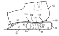
도 19에 도시된 바와 같이, 착용자의 발뒤꿈치(20)의 부하(load)에 대하여, 중심 패널(154)은 중심 패널 부재(154)의 초기 부하 동안 챔버(50)의 정상부(51)의 주위 패널과는 독립적으로 아래 방향으로 편향하도록 구성된다. 도 19에 도시된 바와 같이, 발뒤꿈치(120)가 아래 방향으로 [화살표(101)에 의해 도시됨] 부하를 가하는 경우, 중심 패널(154)은 아래 방향으로 편향한다. 이것은 위에서 설명했던 바와 유사한 점진적 압축 특성을 제공할 수 있다. 또한, 이것은 발뒤꿈치를 감싸 안도록 구성된 리세스를 제공할 수 있다. 그러한 감싸 안는(cradling) 리세스는 안락감 및 횡방향 안정성을 제공할 수 있다.19, the
제3 밑창 구조체 구성Structure of the third sole structure
위에서 설명한 중심 구조들 중 하나 이상을 이용하는 밑창 구조체가 제공될 수 있다. 예를 들어, 하나보다 많은 지지 구조가 적층된 구성으로 이용될 수 있다. 유사하게, 하나보다 많은 인장 부재가 적층되어 비교적 두꺼운 챔버의 높이에 걸치도록 원하는 길이를 달성할 수 있다. 또한, 지지 구조들은 인장 부재들과 적층된 구성으로 결합될 수 있다. 그러한 구성은 지지 구조와 인장 부재를 단일의 밑창 구조체로 하는 이점들을 제공할 수 있다. 예를 들어, 지지 구조는 압축시 수직 지지를 제공할 수 있다. 그러한 지지는 지지 구조가 압축 가능한 실시예들에서 쿠션작용을 포함할 수 있다. 또한, 지지 부재는 밑창 구조체에 많은 양의 무게를 가하지 않으면서 챔버의 상부와 하부 사이에 장력을 제공할 수 있다. 일부 구성들에서, 비교적 두꺼운 (예를 들어, 높은) 가압된 챔버는 위에서 설명한 것과 같은 복수의 연결 구조들을 적층함으로써 최소의 연결 구조가 제공될 수 있다.A sole structure using one or more of the central structures described above may be provided. For example, more than one support structure may be used in a stacked configuration. Similarly, more than one tensile member may be laminated to achieve the desired length to span the height of the relatively thick chamber. Further, the support structures may be combined with the tension members in a laminated configuration. Such a configuration can provide advantages in that the support structure and the tension member are a single sole structure. For example, the support structure may provide vertical support during compression. Such support may include a cushioning action in embodiments in which the support structure is compressible. In addition, the support member can provide tension between the top and bottom of the chamber without exerting a large amount of weight on the sole structure. In some arrangements, a relatively thick (e.g., high) pressurized chamber may be provided with a minimum connection structure by stacking a plurality of connection structures as described above.
도 20은 두 개의 적층된 직물 인장 부재들 위에 적층된 계단형 포옴 기둥을 채용하는 밑창 구조체(30)의 비교적 두꺼운 구성을 예시한다. 도 20에 도시된 바와 같이, 밑창 구조체(30)는 접촉 영역(152) 내의 챔버(50)의 정상부(51)에 부착된 중심 구조(90)를 포함할 수 있다. 접촉 영역(152)을 포함하는 정상부(51)의 영역은 챔버(50)의 정상부(51)의 다른 부분들보다 아래 방향으로 더 연장되어, 챔버(50)의 정상부(51) 내의 리세스(159)를 형성한다(유사한 구성을 위한 도 2 및 도 3 참조). 보강 부재(40)는 챔버(50)의 정상부(51)에 접합된 하면을 갖는 상부(44) 및 상기 하면으로부터 챔버(50)의 정상부(51) 내의 리세스(159) 내로 아래 방향으로 연장되는 지지 구조(43)를 포함할 수 있다. 지지 구조(43)는 실질적으로 챔버(50)의 정상부(51) 내의 리세스(159)를 채운다. 일부 구성들에서, 지지 구조(43)는 위에서 설명한 바와 같이 층이 진 구성 또는 테이퍼진 구성을 가질 수 있다. 예를 들어, 도 20은 지지 구조(43)의 층이 진(계단형) 구성을 도시한다.20 illustrates a relatively thick configuration of a
도 20에 더 도시된 바와 같이, 중심 구조(90)는 인장 부재(81)를 포함할 수도 있다. 인장 부재(81)는 2층 적층된 구성을 가질 수 있다. 예를 들어, 도 20에 도시된 바와 같이, 인장 부재(81)는 정상부 직물 패널(83), 저부 직물 패널(84), 및 정상부 직물 패널(83)과 저부 직물 패널(84) 사이의 대략 중간에 위치된 중간 직물 패널(87)을 포함할 수 있다. 인장 부재(81)는 또한 실질적으로 수직 방향으로 배열된 복수의 직물 슬랫들을 포함할 수 있다. 예를 들어, 인장 부재(81)는 정상부 직물 패널(83)과 중간 직물 패널(87) 사이에서 연장되는 직물 슬랫들(85)의 상부 세트, 및 중간 직물 패널(87)과 저부 직물 패널(84) 사이에서 연장되는 직물 슬랫들(86)의 하부 세트를 포함할 수 있다.As further shown in FIG. 20, the
위에서 설명한 바와 같이, 일부 구성들에서, 챔버(50)의 적어도 일부는 신발류(10)의 노출된 부분을 구성할 수 있다. 예를 들어, 일부 구성들에서, 챔버(51)의 적어도 내측 및 바깥쪽 측부들이 노출되어, 중심 구조(90)가 보여질 수 있도록 만들 수 있다. 그러한 적층된 중심 구조 구성이 이용되어 실질적으로 높은 챔버 실시예들을 형성할 수 있다. 예를 들어, 일부 구성들에서, 챔버(50)는 3/4 인치 내지 2 인치 이상의 높이를 가질 수 있다. 챔버 내에 최소의 중심 구조를 갖는 그러한 높은 투명 챔버가 이용되어 신발류(10)의 밑창 구조체를 들여다 보는 (일부 경우, 그것을 관통해서 보는) 비교적 큰 창(window)을 형성할 수 있다.As described above, in some arrangements, at least a portion of the
그러한 비교적 두꺼운 챔버들은 어떠한 적절한 유형의 신발류에도 이용될 수 있다. 일부 구성들에서, 상당한 힐을 갖는 신발류에서 비교적 두꺼운 챔버들(예를 들어, 두께가 1인치 이상)이 이용될 수 있다. 다른 구현들은 상당한 충격 흡수가 바람직한 고충격 활동들을 위한 신발류를 포함할 수 있다. 예를 들어, 그러한 신발류는 스키 및 스노우보딩 부츠들 (특히, 고충격 착지를 유발하는 에어리얼 트릭 또는 점프에 참가하는 운동선수들에 의해 이용되는 것들)을 포함할 수 있다. 비교적 두꺼운 챔버는, 큰 충격을 흡수하기 위해, 챔버의 정상부와 저부가 서로를 향하여 압축될 수 있는 비교적 긴 이동량을 제공할 수 있다.Such relatively thick chambers may be used in any suitable type of footwear. In some configurations, relatively thick chambers (e.g., one inch or more in thickness) may be used in footwear having substantial heights. Other implementations may include footwear for high impact activities where substantial shock absorption is desirable. For example, such footwear may include ski and snowboarding boots (especially those used by athletes participating in aerial tricks or jumps that cause high impact landing). A relatively thick chamber can provide a relatively long amount of travel that the top and bottom of the chamber can be compressed towards one another to absorb large impacts.
본 발명은 다양한 실시예들을 참조하여 상기 및 첨부 도면들에서 개시된다. 그러나 본 개시에 의해 제공되는 목적은 본 발명에 관련된 다양한 특징들 및 개념들의 일 예를 제공하는 것이지, 본 발명의 범위를 제한하는 것은 아니다. 당업자는 청구범위에 의해 정의된 본 발명의 범위로부터 벗어나지 않고 상기 실시예들에 대하여 다수의 변경 및 변형이 이루어질 수 있는 것을 이해할 것이다.The invention is disclosed above and in the accompanying drawings with reference to various embodiments. However, the object provided by this disclosure is merely to provide an example of various features and concepts related to the present invention, and not to limit the scope of the present invention. Those skilled in the art will appreciate that numerous modifications and variations can be made to the embodiments without departing from the scope of the invention as defined by the claims.
Claims (22)
유체 충전 챔버의 제1 표면에 제1 리세스를 형성하는 단계; 및
상부와 제1 지지 구조를 갖는 보강 부재를 상기 유체 충전 챔버의 제1 표면에 부착하는 단계
를 포함하고, 상기 제1 지지 구조는, 상기 상부로부터 상기 유체 충전 챔버의 제1 리세스 내로 연장되는 것인 신발류 물품용 밑창 구조체를 제조하는 방법.A method of making a sole structure for a footwear article,
Forming a first recess on a first surface of the fluid fill chamber; And
Attaching a reinforcement member having an upper portion and a first support structure to a first surface of the fluid fill chamber,
Wherein the first support structure extends from the top into the first recess of the fluid fill chamber.
상기 유체 충전 챔버의 재료보다 더 강성인 재료로 상기 보강 부재를 형성하는 단계를 더 포함하는 신발류 물품용 밑창 구조체를 제조하는 방법.The method according to claim 1,
Further comprising forming the reinforcing member with a material that is stiffer than the material of the fluid filling chamber.
보강 부재를 상기 유체 충전 챔버에 부착하는 단계는, 플레이트를 상기 유체 충전 챔버에 부착하는 단계를 포함하는 것인 신발류 물품용 밑창 구조체를 제조하는 방법.The method according to claim 1,
Wherein attaching a reinforcing member to the fluid fill chamber comprises attaching a plate to the fluid fill chamber.
강성 재료로 상기 보강 부재를 형성하는 단계 및 압축성 재료로 상기 제1 지지 구조를 형성하는 단계를 더 포함하는 신발류 물품용 밑창 구조체를 제조하는 방법.The method according to claim 1,
Further comprising forming the reinforcing member with a rigid material and forming the first support structure with a compressible material.
강성 재료로 상기 보강 부재를 형성하는 단계는, 합성 재료, 폴리우레탄 및/또는 비닐로 상기 보강 부재를 형성하는 단계를 포함하는 것인 신발류 물품용 밑창 구조체를 제조하는 방법.5. The method of claim 4,
Wherein forming the reinforcing member with a rigid material comprises forming the reinforcing member with a synthetic material, polyurethane and / or vinyl.
합성 재료로 상기 보강 부재를 형성하는 단계는, 탄소 섬유로 상기 보강 부재를 형성하는 단계를 포함하는 것인 신발류 물품용 밑창 구조체를 제조하는 방법.6. The method of claim 5,
Wherein forming the reinforcing member with a synthetic material comprises forming the reinforcing member with carbon fibers.
압축성 재료로 상기 제1 지지 구조를 형성하는 단계는, 포옴(foam)으로 상기 제1 지지 구조를 형성하는 단계를 포함하는 것인 신발류 물품용 밑창 구조체를 제조하는 방법.5. The method of claim 4,
Wherein forming the first support structure with a compressible material comprises forming the first support structure with foam. ≪ RTI ID = 0.0 > 11. < / RTI >
상기 보강 부재를 상기 유체 충전 챔버에 부착하는 단계는, 상기 보강 부재의 주변 에지가 상기 유체 충전 챔버의 주변 에지로부터 이격되는 단계를 포함하는 것인 신발류 물품용 밑창 구조체를 제조하는 방법.The method according to claim 1,
Wherein attaching the stiffening member to the fluid fill chamber comprises spacing the peripheral edge of the stiffening member away from a peripheral edge of the fluid fill chamber.
상기 밑창 구조체의 실질적인 전체 길이에 걸쳐 상기 보강 부재 및 상기 유체 충전 챔버가 연장되는 단계를 더 포함하는 신발류 물품용 밑창 구조체를 제조하는 방법.The method according to claim 1,
Further comprising extending the stiffening member and the fluid fill chamber over substantially the entire length of the sole structure.
상기 유체 충전 챔버의 제1 표면에 제2 리세스를 형성하는 단계 및 상기 상부에 매달리는 제2 지지 구조를 갖는 상기 보강 부재를 제공하는 단계를 더 포함하고, 상기 제2 지지 구조는 상기 상부로부터 상기 유체 충전 챔버의 제2 리세스 내로 연장되는 것인 신발류 물품용 밑창 구조체를 제조하는 방법.The method according to claim 1,
Further comprising providing the reinforcement member having a second support structure on the first surface and a second recess on the first surface of the fluid fill chamber, the second support structure being suspended from the top, And extends into the second recess of the fluid filling chamber.
상기 유체 충전 챔버의 제1 표면에 제2 리세스를 형성하는 단계는, 상기 제2 리세스가 제1 리세스로부터 이격되는 단계를 포함하는 것인 신발류 물품용 밑창 구조체를 제조하는 방법.11. The method of claim 10,
Wherein forming a second recess on a first surface of the fluid fill chamber comprises spacing the second recess away from the first recess.
상기 유체 충전 챔버로부터 분리된 상기 보강 부재를 형성하는 단계를 더 포함하는 신발류 물품용 밑창 구조체를 제조하는 방법.The method according to claim 1,
Further comprising forming the reinforcing member separated from the fluid filling chamber. ≪ Desc / Clms Page number 21 >
블래더 재료(bladder material)의 블랭크를 몰드 내로 삽입하는 단계를 더 포함하고, 상기 유체 충전 챔버를 형성하는 단계는, 상기 몰드 내의 상기 블래더 재료의 블랭크에 열과 압력을 가하는 단계를 포함하는 것인 신발류 물품용 밑창 구조체를 제조하는 방법.13. The method of claim 12,
Further comprising inserting a blank of the bladder material into the mold, wherein forming the fluid fill chamber comprises applying heat and pressure to the blank of the bladder material in the mold, A method for manufacturing a sole structure for a footwear article.
상기 블래더 재료의 블랭크에 열과 압력을 가하기 전에, 상기 보강 부재를 상기 블래더 재료의 블랭크에 인접한 상기 몰드 내로 삽입하는 단계를 더 포함하는 신발류 물품용 밑창 구조체를 제조하는 방법.14. The method of claim 13,
Further comprising inserting the reinforcing member into the mold adjacent the blank of the bladder material prior to applying heat and pressure to the blank of the bladder material.
상기 보강 부재가 상기 몰드 내에 배치될 때, 상기 블래더 재료의 블랭크에 열과 압력을 가하는 단계를 더 포함하는 신발류 물품용 밑창 구조체를 제조하는 방법.15. The method of claim 14,
Further comprising applying heat and pressure to a blank of the bladder material when the stiffening member is disposed within the mold.
블래더 재료의 블랭크를 상기 몰드 내로 삽입하는 단계는, 제1 시트 및 제2 시트를 상기 몰드 내로 삽입하는 단계를 포함하는 것인 신발류 물품용 밑창 구조체를 제조하는 방법.14. The method of claim 13,
Wherein inserting a blank of bladder material into the mold comprises inserting a first sheet and a second sheet into the mold.
상기 유체 충전 챔버의 상기 제1 표면에 상기 제1 리세스를 형성하는 단계는, 상기 제1 리세스에서 상기 제1 시트를 상기 제2 시트에 접합하는 단계를 포함하는 것인 신발류 물품용 밑창 구조체를 제조하는 방법.17. The method of claim 16,
Wherein forming the first recess on the first surface of the fluid fill chamber comprises bonding the first sheet to the second seat at the first recess. ≪ / RTI >
상기 보강 부재를 상기 유체 충전 챔버에 부착하는 단계는, 상기 상부의 오목면을 상기 유체 충전 챔버의 상기 제1 표면의 볼록면에 부착하는 단계를 포함하는 것인 신발류 물품용 밑창 구조체를 제조하는 방법.The method according to claim 1,
Wherein attaching the stiffening member to the fluid fill chamber comprises attaching the top concave surface to the convex surface of the first surface of the fluid fill chamber. .
상기 보강 부재를 상기 유체 충전 챔버에 부착하는 단계는, 상기 보강 부재를 상기 유체 충전 챔버의 상기 제1 표면에 접합하는 단계를 포함하는 것인 신발류 물품용 밑창 구조체를 제조하는 방법.The method according to claim 1,
Wherein attaching the reinforcing member to the fluid fill chamber comprises bonding the reinforcement member to the first surface of the fluid fill chamber.
상기 상부와는 다른 재료로 상기 제1 지지 구조를 형성하는 단계를 더 포함하는 신발류 물품용 밑창 구조체를 제조하는 방법.The method according to claim 1,
Further comprising forming the first support structure with a different material from the top. ≪ Desc / Clms Page number 17 >
상기 상부보다 더 압축성 재료로 상기 제1 지지 구조를 형성하는 단계를 더 포함하는 신발류 물품용 밑창 구조체를 제조하는 방법.The method according to claim 1,
Further comprising forming the first support structure with a more compressible material than the upper portion. ≪ RTI ID = 0.0 > 31. < / RTI >
상기 제1 표면보다 상기 유체 충전 챔버의 대향하는 측면 상에 배치된 상기 유체 충전 챔버의 제2 표면에서, 바깥창을 상기 유체 충전 챔버에 부착하는 단계를 더 포함하는 신발류 물품용 밑창 구조체를 제조하는 방법.
The method according to claim 1,
Further comprising attaching an outsole to the fluid fill chamber at a second surface of the fluid fill chamber disposed on an opposite side of the fluid fill chamber than the first surface, Way.
Applications Claiming Priority (3)
| Application Number | Priority Date | Filing Date | Title |
|---|---|---|---|
| US13/790,501 | 2013-03-08 | ||
| US13/790,501 US10806214B2 (en) | 2013-03-08 | 2013-03-08 | Footwear fluid-filled chamber having central tensile feature |
| PCT/US2014/020961 WO2014138322A1 (en) | 2013-03-08 | 2014-03-06 | Footwear fluid-filled chamber having central tensile feature |
Related Parent Applications (1)
| Application Number | Title | Priority Date | Filing Date |
|---|---|---|---|
| KR1020157026980A Division KR101893181B1 (en) | 2013-03-08 | 2014-03-06 | Footwear fluid-filled chamber having central tensile feature |
Publications (2)
| Publication Number | Publication Date |
|---|---|
| KR20180098422A true KR20180098422A (en) | 2018-09-03 |
| KR102135439B1 KR102135439B1 (en) | 2020-07-17 |
Family
ID=50639898
Family Applications (2)
| Application Number | Title | Priority Date | Filing Date |
|---|---|---|---|
| KR1020157026980A Active KR101893181B1 (en) | 2013-03-08 | 2014-03-06 | Footwear fluid-filled chamber having central tensile feature |
| KR1020187024380A Active KR102135439B1 (en) | 2013-03-08 | 2014-03-06 | Footwear fluid-filled chamber having central tensile feature |
Family Applications Before (1)
| Application Number | Title | Priority Date | Filing Date |
|---|---|---|---|
| KR1020157026980A Active KR101893181B1 (en) | 2013-03-08 | 2014-03-06 | Footwear fluid-filled chamber having central tensile feature |
Country Status (6)
| Country | Link |
|---|---|
| US (3) | US10806214B2 (en) |
| EP (3) | EP2964045B1 (en) |
| JP (2) | JP6549488B2 (en) |
| KR (2) | KR101893181B1 (en) |
| CN (2) | CN105101830B (en) |
| WO (1) | WO2014138322A1 (en) |
Families Citing this family (44)
| Publication number | Priority date | Publication date | Assignee | Title |
|---|---|---|---|---|
| US9987814B2 (en) | 2013-02-21 | 2018-06-05 | Nike, Inc. | Method of co-molding |
| US11039662B2 (en) | 2009-12-03 | 2021-06-22 | Nike, Inc. | Tethered fluid-filled chamber with multiple tether configurations |
| US9750307B2 (en) | 2013-02-21 | 2017-09-05 | Nike, Inc. | Article of footwear having a sole structure including a fluid-filled chamber and an outsole, the sole structure, and methods for manufacturing |
| US9894959B2 (en) * | 2009-12-03 | 2018-02-20 | Nike, Inc. | Tethered fluid-filled chamber with multiple tether configurations |
| US9872535B2 (en) * | 2012-12-20 | 2018-01-23 | Nike, Inc. | Article of footwear with a harness and fluid-filled chamber arrangement |
| US10806214B2 (en) * | 2013-03-08 | 2020-10-20 | Nike, Inc. | Footwear fluid-filled chamber having central tensile feature |
| EP3267828B1 (en) * | 2015-03-09 | 2020-06-03 | Nike Innovate C.V. | Method of co-molding |
| WO2016144649A1 (en) * | 2015-03-09 | 2016-09-15 | Nike Innovate C.V. | A sole structure for an article of footwear, including a fluid-filled chamber and an outsole, and methods for manufacturing |
| EP3280501B1 (en) | 2015-04-08 | 2020-04-01 | NIKE Innovate C.V. | Article with a cushioning assembly having inner and outer bladder elements with interfitting features and method of manufacturing an article |
| EP3552509B1 (en) | 2015-04-08 | 2021-03-17 | NIKE Innovate C.V. | Article with a cushioning assembly having inner and outer bladder elements and a reinforcement element and method of manufacturing an article |
| CN107405851B (en) | 2015-04-21 | 2019-10-22 | 耐克创新有限合伙公司 | Capsule-like element formed from three sheets and method of making a pouch-like element |
| US10448704B2 (en) * | 2015-10-02 | 2019-10-22 | Nike, Inc. | Plate with foam for footwear |
| JP3221315U (en) * | 2016-03-15 | 2019-05-23 | ナイキ イノヴェイト シーヴィーNike Innovate C.V. | Footwear having first and second outsole components |
| US10130137B2 (en) * | 2016-07-22 | 2018-11-20 | D'Wayne Edwards | Flexible footwear article and method of manufacture |
| KR102326973B1 (en) | 2017-05-23 | 2021-11-16 | 나이키 이노베이트 씨.브이. | Midsole with graded response |
| EP4140349A1 (en) | 2017-05-23 | 2023-03-01 | Nike Innovate C.V. | Domed midsole with staged compressive stiffness |
| CN113598471B (en) | 2017-05-23 | 2022-08-09 | 耐克创新有限合伙公司 | Midsole system with graded response |
| WO2019060242A1 (en) * | 2017-09-21 | 2019-03-28 | O2 Partners, Llc | Improved method for the manufacture of inner soles |
| USD954412S1 (en) * | 2017-12-01 | 2022-06-14 | Nike, Inc. | Shoe |
| USD923306S1 (en) | 2017-12-01 | 2021-06-29 | Nike, Inc. | Shoe |
| USD912964S1 (en) | 2018-01-29 | 2021-03-16 | Nike, Inc. | Shoe |
| US10149513B1 (en) * | 2018-01-31 | 2018-12-11 | Nike, Inc. | Sole structure for article of footwear |
| WO2019195089A1 (en) * | 2018-04-03 | 2019-10-10 | Wolverine Outdoors, Inc. | System and method for customizing footwear |
| USD874104S1 (en) * | 2018-05-18 | 2020-02-04 | Nike, Inc. | Shoe |
| USD933341S1 (en) * | 2018-05-18 | 2021-10-19 | Nike, Inc. | Shoe |
| CN110721440A (en) * | 2018-07-16 | 2020-01-24 | 王尧 | Foot arch training shoe |
| CN121220849A (en) * | 2018-07-31 | 2025-12-30 | 耐克创新有限合伙公司 | Sole structure for footwear |
| USD861303S1 (en) * | 2018-09-13 | 2019-10-01 | Nike, Inc. | Shoe |
| USD866140S1 (en) * | 2019-01-10 | 2019-11-12 | Nike, Inc. | Shoe |
| US11730233B2 (en) * | 2019-05-30 | 2023-08-22 | Nike, Inc. | Sole structure for article of footwear |
| USD912949S1 (en) * | 2019-08-30 | 2021-03-16 | Nike, Inc. | Shoe |
| USD936944S1 (en) * | 2019-09-06 | 2021-11-30 | Nike, Inc. | Shoe |
| WO2021242832A1 (en) * | 2020-05-29 | 2021-12-02 | Nike Innovate C.V. | Sole structure for article of footwear |
| USD932158S1 (en) * | 2020-10-29 | 2021-10-05 | Nike, Inc. | Shoe |
| US12295451B2 (en) | 2020-11-05 | 2025-05-13 | Fuerst Group, Inc. | Article of footwear with heel cushion |
| USD929726S1 (en) * | 2021-01-13 | 2021-09-07 | Nike, Inc. | Cushioning device for footwear |
| USD929725S1 (en) * | 2021-01-13 | 2021-09-07 | Nike, Inc. | Cushioning device for footwear |
| USD929100S1 (en) * | 2021-01-13 | 2021-08-31 | Nike, Inc. | Cushioning device for footwear |
| USD929723S1 (en) * | 2021-01-13 | 2021-09-07 | Nike, Inc. | Cushioning device for footwear |
| USD929724S1 (en) * | 2021-01-13 | 2021-09-07 | Nike, Inc. | Cushioning device for footwear |
| WO2022183627A1 (en) * | 2021-03-01 | 2022-09-09 | 安踏(中国)有限公司 | Sole shock-absorbing piece and sole |
| CN115195176A (en) * | 2021-04-13 | 2022-10-18 | 安踏(中国)有限公司 | Shoe forming process and shoe |
| EP4496490A1 (en) * | 2022-03-23 | 2025-01-29 | NIKE Innovate C.V. | Article of footwear comprising a sole structure |
| USD1046401S1 (en) * | 2023-02-03 | 2024-10-15 | Nike, Inc. | Shoe |
Citations (4)
| Publication number | Priority date | Publication date | Assignee | Title |
|---|---|---|---|---|
| US5575088A (en) * | 1991-09-27 | 1996-11-19 | Converse Inc. | Shoe sole with reactive energy fluid filled toroid apparatus |
| US6374514B1 (en) * | 2000-03-16 | 2002-04-23 | Nike, Inc. | Footwear having a bladder with support members |
| WO2003063629A1 (en) * | 2002-01-28 | 2003-08-07 | Yokohama Tlo Company, Ltd. | Shoe |
| US20090151196A1 (en) * | 2007-12-17 | 2009-06-18 | Nike, Inc. | Article Of Footwear Having A Sole Structure With A Fluid-Filled Chamber |
Family Cites Families (177)
| Publication number | Priority date | Publication date | Assignee | Title |
|---|---|---|---|---|
| DE135595C (en) | ||||
| US836364A (en) * | 1906-02-05 | 1906-11-20 | E A G Busby | Detachable tread for boots and shoes. |
| US1506975A (en) * | 1922-08-21 | 1924-09-02 | Cooney Charles | Boot and shoe having inflated air cushion inserted in the sole and heel thereof |
| US2080469A (en) * | 1933-05-17 | 1937-05-18 | Levi L Gilbert | Pneumatic foot support |
| US2532742A (en) * | 1949-02-17 | 1950-12-05 | Stoiner Stephen | Cushion heel |
| US2645865A (en) * | 1952-07-25 | 1953-07-21 | Edward W Town | Cushioning insole for shoes |
| US3335045A (en) * | 1964-06-15 | 1967-08-08 | Post Louis | Method for making an inflatable article |
| US3205106A (en) | 1964-07-16 | 1965-09-07 | Goodyear Aerospace Corp | Method of increasing stiffness of an inflated structure |
| US4183156A (en) | 1977-01-14 | 1980-01-15 | Robert C. Bogert | Insole construction for articles of footwear |
| US4340626A (en) | 1978-05-05 | 1982-07-20 | Rudy Marion F | Diffusion pumping apparatus self-inflating device |
| US4187620A (en) * | 1978-06-15 | 1980-02-12 | Selner Allen J | Biomechanical shoe |
| US4219945B1 (en) | 1978-06-26 | 1993-10-19 | Robert C. Bogert | Footwear |
| US4271606A (en) * | 1979-10-15 | 1981-06-09 | Robert C. Bogert | Shoes with studded soles |
| US4342158A (en) * | 1980-06-19 | 1982-08-03 | Mcmahon Thomas A | Biomechanically tuned shoe construction |
| US4541185A (en) * | 1983-09-26 | 1985-09-17 | Chou Jin Jong | Game shoe |
| US4521979A (en) * | 1984-03-01 | 1985-06-11 | Blaser Anton J | Shock absorbing shoe sole |
| US4759136A (en) * | 1987-02-06 | 1988-07-26 | Reebok International Ltd. | Athletic shoe with dynamic cradle |
| US5025575A (en) * | 1989-03-14 | 1991-06-25 | Nikola Lakic | Inflatable sole lining for shoes and boots |
| IT1204662B (en) | 1987-05-29 | 1989-03-10 | Armenak Moumdjian | PNEUMATIC CHAMBER INSOLE FOR FOOTWEAR, MOLD AND FORMING METHOD RELATED |
| US5199191A (en) * | 1987-05-29 | 1993-04-06 | Armenak Moumdjian | Athletic shoe with inflatable mobile inner sole |
| US5005300A (en) * | 1987-07-06 | 1991-04-09 | Reebok International Ltd. | Tubular cushioning system for shoes |
| US4817304A (en) * | 1987-08-31 | 1989-04-04 | Nike, Inc. And Nike International Ltd. | Footwear with adjustable viscoelastic unit |
| US5046267A (en) * | 1987-11-06 | 1991-09-10 | Nike, Inc. | Athletic shoe with pronation control device |
| DE3802607A1 (en) * | 1987-12-17 | 1989-06-29 | Adidas Sportschuhe | OUTSOLE FOR SPORTSHOES |
| MY106949A (en) | 1988-02-05 | 1995-08-30 | Rudy Marion F | Pressurizable envelope and method |
| US4936029A (en) | 1989-01-19 | 1990-06-26 | R. C. Bogert | Load carrying cushioning device with improved barrier material for control of diffusion pumping |
| US5042176A (en) | 1989-01-19 | 1991-08-27 | Robert C. Bogert | Load carrying cushioning device with improved barrier material for control of diffusion pumping |
| DE8901236U1 (en) * | 1989-02-03 | 1990-06-07 | Puma Ag Rudolf Dassler Sport, 91074 Herzogenaurach | Shoe, especially sports shoe or rehabilitation shoe |
| IT1226514B (en) * | 1989-05-24 | 1991-01-24 | Fila Sport | SPORTS FOOTWEAR INCORPORATING, IN THE HEEL, AN ELASTIC INSERT. |
| FR2851130B1 (en) * | 2003-02-14 | 2005-06-24 | Salomon Sa | SHOE WEEK |
| US5564202A (en) * | 1990-05-24 | 1996-10-15 | Hoppenstein; Reuben | Hydropneumatic support system for footwear |
| US5131174A (en) * | 1990-08-27 | 1992-07-21 | Alden Laboratories, Inc. | Self-reinitializing padding device |
| US5353523A (en) * | 1991-08-02 | 1994-10-11 | Nike, Inc. | Shoe with an improved midsole |
| EP0605485B2 (en) * | 1991-09-26 | 2005-03-30 | Skydex Technologies, Inc. | Shoe sole component |
| US5572804A (en) | 1991-09-26 | 1996-11-12 | Retama Technology Corp. | Shoe sole component and shoe sole component construction method |
| US5220737A (en) * | 1991-09-27 | 1993-06-22 | Converse Inc. | Shoe sole having improved lateral and medial stability |
| WO1994013164A1 (en) | 1992-12-10 | 1994-06-23 | Nike International Ltd. | Bonding of rubber to plastic in footwear |
| TW234081B (en) * | 1993-02-04 | 1994-11-11 | Converse Inc | |
| US5353459A (en) * | 1993-09-01 | 1994-10-11 | Nike, Inc. | Method for inflating a bladder |
| US6453577B1 (en) * | 1996-02-09 | 2002-09-24 | Reebok International Ltd. | Support and cushioning system for an article of footwear |
| US5952065A (en) * | 1994-08-31 | 1999-09-14 | Nike, Inc. | Cushioning device with improved flexible barrier membrane |
| TW286269B (en) * | 1994-11-28 | 1996-09-21 | Marion Frank Rudy | |
| US6013340A (en) | 1995-06-07 | 2000-01-11 | Nike, Inc. | Membranes of polyurethane based materials including polyester polyols |
| JP4210328B2 (en) | 1995-06-07 | 2009-01-14 | ナイキ,インコーポレイテッド | Membranes made of polyurethane-based materials containing polyester polyols |
| US5718063A (en) * | 1995-07-17 | 1998-02-17 | Asics Corporation | Midsole cushioning system |
| US5741568A (en) * | 1995-08-18 | 1998-04-21 | Robert C. Bogert | Shock absorbing cushion |
| US5918383A (en) * | 1995-10-16 | 1999-07-06 | Fila U.S.A., Inc. | Sports shoe having an elastic insert |
| US5842291A (en) * | 1995-10-26 | 1998-12-01 | Energaire Corporation | Thrust producing multiple channel-multiple chamber shoe and bladder |
| US5864968A (en) * | 1997-03-07 | 1999-02-02 | Mann; Morris A. | Shoe with perfluoropolyether insole |
| JPH10327906A (en) | 1997-05-30 | 1998-12-15 | Asahi Corp | Shock absorber for soles of soles |
| IT1292147B1 (en) * | 1997-06-12 | 1999-01-25 | Global Sports Tech Inc | SPORTS FOOTWEAR INCORPORATING A PLURALITY OF INSERTS HAVING DIFFERENT ELASTIC RESPONSES TO FOOT STRESS |
| US5815950A (en) * | 1997-09-11 | 1998-10-06 | Wang; Sui-Mu | Air-cushioning sole insert lined with iridescent film |
| US6029962A (en) | 1997-10-24 | 2000-02-29 | Retama Technology Corporation | Shock absorbing component and construction method |
| US5930918A (en) * | 1997-11-18 | 1999-08-03 | Converse Inc. | Shoe with dual cushioning component |
| US5901467A (en) * | 1997-12-11 | 1999-05-11 | American Sporting Goods Corporation | Shoe construction including pneumatic shock attenuation members |
| US5993585A (en) * | 1998-01-09 | 1999-11-30 | Nike, Inc. | Resilient bladder for use in footwear and method of making the bladder |
| US20020121031A1 (en) * | 1998-01-30 | 2002-09-05 | Steven Smith | 2a improvements |
| US6009637A (en) * | 1998-03-02 | 2000-01-04 | Pavone; Luigi Alessio | Helium footwear sole |
| US5956869A (en) * | 1998-03-06 | 1999-09-28 | Energaire Corporation | Shoe sole construction with mesh liner for mid-sole cavity |
| KR19980025330A (en) * | 1998-04-14 | 1998-07-06 | 전정효 | Shock Absorption System for Shoes |
| JPH11318507A (en) | 1998-05-15 | 1999-11-24 | Mizuno Corp | Golf shoe sole and method of manufacturing the sole |
| USD409363S (en) * | 1998-09-01 | 1999-05-11 | Nike, Inc. | Bladder for a shoe sole |
| US6127026A (en) | 1998-09-11 | 2000-10-03 | Nike, Inc. | Flexible membranes |
| US6082025A (en) | 1998-09-11 | 2000-07-04 | Nike, Inc. | Flexible membranes |
| US6205684B1 (en) * | 1998-11-13 | 2001-03-27 | Zephyr Athletic Footwear, Inc. | Strike pad assembly |
| US6170173B1 (en) * | 1999-05-18 | 2001-01-09 | Gayford Caston | Method and apparatus for fluid flow transfer in shoes |
| US6176025B1 (en) * | 1999-05-28 | 2001-01-23 | Spalding Sports Worldwide, Inc. | Cushioning system for golf shoes |
| US6553691B2 (en) * | 1999-09-02 | 2003-04-29 | Ing-Chung Huang | Self-inflatable air cushion for shoes |
| US6510624B1 (en) * | 1999-09-10 | 2003-01-28 | Nikola Lakic | Inflatable lining for footwear with protective and comfortable coatings or surrounds |
| US6976321B1 (en) * | 2002-11-07 | 2005-12-20 | Nikola Lakic | Adjustable air cushion insole with additional upper chamber |
| US6354020B1 (en) * | 1999-09-16 | 2002-03-12 | Reebok International Ltd. | Support and cushioning system for an article of footwear |
| US7225564B1 (en) * | 1999-12-10 | 2007-06-05 | Srl, Inc. | Shoe outsole |
| US6385864B1 (en) * | 2000-03-16 | 2002-05-14 | Nike, Inc. | Footwear bladder with controlled flex tensile member |
| US6457262B1 (en) * | 2000-03-16 | 2002-10-01 | Nike, Inc. | Article of footwear with a motion control device |
| US6589614B2 (en) * | 2000-08-17 | 2003-07-08 | Bmc Players | Cushioning device for an athletic shoe |
| US6777062B2 (en) | 2000-10-12 | 2004-08-17 | Skydex Technologies, Inc. | Cushioning structure for floor and ground surfaces |
| US6665957B2 (en) * | 2000-10-19 | 2003-12-23 | Shoe Spring, Inc. | Fluid flow system for spring-cushioned shoe |
| KR20020032246A (en) * | 2000-10-26 | 2002-05-03 | 김갑진 | shoes with a ventilating coverlet |
| US7000334B2 (en) * | 2001-02-16 | 2006-02-21 | Srl, Inc. | Shoe outsole |
| DE10112821B9 (en) * | 2001-03-16 | 2004-10-28 | Adidas International Marketing B.V. | Sole and shoe |
| US6598251B2 (en) * | 2001-06-15 | 2003-07-29 | Hon Technology Inc. | Body support system |
| US20020194747A1 (en) * | 2001-06-21 | 2002-12-26 | Passke Joel L. | Footwear with bladder filter |
| US6694642B2 (en) * | 2001-09-28 | 2004-02-24 | American Sporting Goods Corporation | Shoe incorporating improved shock absorption and stabilizing elements |
| US7131218B2 (en) * | 2004-02-23 | 2006-11-07 | Nike, Inc. | Fluid-filled bladder incorporating a foam tensile member |
| US20030097767A1 (en) * | 2001-11-28 | 2003-05-29 | Perkinson Jermaine Derelle | 4-E.V.A system |
| US6754982B2 (en) * | 2001-11-30 | 2004-06-29 | Wolverine World Wide, Inc. | Shoe cushioning system and related method of manufacture |
| BRPI0306189A2 (en) * | 2002-01-04 | 2016-06-28 | New Balance Athletic Shoe Inc | shoe sole and cushioning for a shoe sole |
| US6796056B2 (en) * | 2002-05-09 | 2004-09-28 | Nike, Inc. | Footwear sole component with a single sealed chamber |
| US6745499B2 (en) * | 2002-05-24 | 2004-06-08 | Reebok International Ltd. | Shoe sole having a resilient insert |
| US6782641B2 (en) * | 2002-08-12 | 2004-08-31 | American Sporting Goods Corporation | Heel construction for footwear |
| US20040098882A1 (en) * | 2002-11-26 | 2004-05-27 | Wei-Jei Tuan | Airbag buffer for footwear |
| US6946050B2 (en) * | 2003-01-27 | 2005-09-20 | Nike, Llc | Method for flange bonding |
| US20040154189A1 (en) * | 2003-02-12 | 2004-08-12 | Wang Swei Mu | Shoe sole structure |
| ITTV20030095A1 (en) * | 2003-07-14 | 2005-01-15 | Asolo Spa | FOOTWEAR WITH COMPOSITE INSOLE. |
| US7707744B2 (en) * | 2003-07-16 | 2010-05-04 | Nike, Inc. | Footwear with a sole structure incorporating a lobed fluid-filled chamber |
| US7707745B2 (en) * | 2003-07-16 | 2010-05-04 | Nike, Inc. | Footwear with a sole structure incorporating a lobed fluid-filled chamber |
| US7000335B2 (en) * | 2003-07-16 | 2006-02-21 | Nike, Inc. | Footwear with a sole structure incorporating a lobed fluid-filled chamber |
| US7128796B2 (en) * | 2003-07-16 | 2006-10-31 | Nike, Inc. | Footwear with a sole structure incorporating a lobed fluid-filled chamber |
| US7051456B2 (en) * | 2003-07-29 | 2006-05-30 | Nike, Inc. | Article of footwear incorporating an inflatable chamber |
| US6931764B2 (en) * | 2003-08-04 | 2005-08-23 | Nike, Inc. | Footwear sole structure incorporating a cushioning component |
| US7070845B2 (en) * | 2003-08-18 | 2006-07-04 | Nike, Inc. | Fluid-filled bladder for an article of footwear |
| US7331124B2 (en) * | 2003-08-22 | 2008-02-19 | Akeva L.L.C. | Plate support for athletic shoe |
| US7020988B1 (en) * | 2003-08-29 | 2006-04-04 | Pierre Andre Senizergues | Footwear with enhanced impact protection |
| US7096605B1 (en) * | 2003-10-08 | 2006-08-29 | Nike, Inc. | Article of footwear having an embedded plate structure |
| US7353625B2 (en) * | 2003-11-03 | 2008-04-08 | Reebok International, Ltd. | Resilient cushioning device for the heel portion of a sole |
| US7076891B2 (en) * | 2003-11-12 | 2006-07-18 | Nike, Inc. | Flexible fluid-filled bladder for an article of footwear |
| US7562469B2 (en) * | 2003-12-23 | 2009-07-21 | Nike, Inc. | Footwear with fluid-filled bladder and a reinforcing structure |
| ATE524305T1 (en) * | 2003-12-23 | 2011-09-15 | Nike International Ltd | FLUID-FILLED BLADDER WITH A REINFORCEMENT STRUCTURE |
| US7086180B2 (en) * | 2003-12-23 | 2006-08-08 | Nike, Inc. | Article of footwear having a fluid-filled bladder with a reinforcing structure |
| US7200955B2 (en) * | 2004-06-04 | 2007-04-10 | Nike, Inc. | Article of footwear incorporating a sole structure with compressible inserts |
| US7152343B2 (en) * | 2004-06-25 | 2006-12-26 | Cronus, Inc. | Footwear system |
| US7334349B2 (en) * | 2004-08-24 | 2008-02-26 | Nike, Inc. | Midsole element for an article of footwear |
| US20060086003A1 (en) * | 2004-10-22 | 2006-04-27 | Yu-Sheng Tseng | Shoe sole with air cushion |
| CA2630817C (en) * | 2004-11-22 | 2016-10-18 | Frampton E. Ellis | Devices with internal flexibility sipes, including siped chambers for footwear |
| US9078491B2 (en) * | 2004-11-29 | 2015-07-14 | Nike, Inc. | Impact-attenuating elements removably mounted in footwear or other products |
| US7574760B2 (en) | 2005-01-05 | 2009-08-18 | Skydex Technologies, Inc. | Cushioning system with parallel sheets having opposing indentions for linear deflection under load |
| DE202005001005U1 (en) | 2005-01-22 | 2006-06-08 | Puma Aktiengesellschaft Rudolf Dassler Sport | Shoe, in particular sports shoe |
| US7249425B2 (en) * | 2005-04-12 | 2007-07-31 | Swei Mu Wang | Shoe sole having soft cushioning device |
| US7464490B2 (en) * | 2005-06-06 | 2008-12-16 | Columbia Insurance Company | Multilayered sole |
| US7533477B2 (en) | 2005-10-03 | 2009-05-19 | Nike, Inc. | Article of footwear with a sole structure having fluid-filled support elements |
| US7395616B2 (en) * | 2005-10-14 | 2008-07-08 | Nike, Inc. | Article of footwear with a pivoting sole element |
| US20100058616A1 (en) * | 2006-05-23 | 2010-03-11 | Hyun-Wook Ryoo | Shoe having an elastic body |
| US20110162233A1 (en) * | 2006-06-27 | 2011-07-07 | Dah Lih Puh Co., Ltd | Air cushion with multistage shock-absorbing assembly and fabricating method |
| JP4520968B2 (en) * | 2006-08-24 | 2010-08-11 | 美津濃株式会社 | Sole sole structure |
| WO2008051165A1 (en) * | 2006-10-27 | 2008-05-02 | Osim International Ltd | An air bag and an apparatus and system having the same |
| US8015730B2 (en) * | 2007-01-08 | 2011-09-13 | Nike, Inc. | Footwear with vertically-arranged pump and pressure chambers |
| US7810255B2 (en) | 2007-02-06 | 2010-10-12 | Nike, Inc. | Interlocking fluid-filled chambers for an article of footwear |
| US20080189982A1 (en) * | 2007-02-09 | 2008-08-14 | Krafsur Andrew B | Shoe spring sole insert |
| US7950167B2 (en) * | 2007-05-22 | 2011-05-31 | Wolverine World Wide, Inc. | Adjustable footwear sole construction |
| US8978273B2 (en) * | 2007-10-19 | 2015-03-17 | Nike, Inc. | Article of footwear with a sole structure having fluid-filled support elements |
| US8125796B2 (en) * | 2007-11-21 | 2012-02-28 | Frampton E. Ellis | Devices with faraday cages and internal flexibility sipes |
| US8241450B2 (en) | 2007-12-17 | 2012-08-14 | Nike, Inc. | Method for inflating a fluid-filled chamber |
| US8178022B2 (en) * | 2007-12-17 | 2012-05-15 | Nike, Inc. | Method of manufacturing an article of footwear with a fluid-filled chamber |
| US7937856B2 (en) * | 2007-12-21 | 2011-05-10 | Nike, Inc. | Article of footwear with illuminated chamber |
| US8341857B2 (en) * | 2008-01-16 | 2013-01-01 | Nike, Inc. | Fluid-filled chamber with a reinforced surface |
| US7966749B2 (en) * | 2008-02-08 | 2011-06-28 | Reebok International Ltd. | Multi-chamber cushion for footwear |
| JP4874349B2 (en) * | 2008-03-31 | 2012-02-15 | 美津濃株式会社 | Sole sole structure |
| US8241451B2 (en) | 2008-05-20 | 2012-08-14 | Nike, Inc. | Contoured fluid-filled chamber with a tensile member |
| EP2132999B1 (en) * | 2008-06-11 | 2015-10-28 | Zurinvest AG | Shoe sole element |
| US9055782B2 (en) * | 2008-10-24 | 2015-06-16 | Kevin McDonnell | Multistructural support system for a sole in a running shoe |
| US8087187B2 (en) * | 2008-11-06 | 2012-01-03 | Nike, Inc. | Article of footwear with support assemblies |
| US8943709B2 (en) * | 2008-11-06 | 2015-02-03 | Nike, Inc. | Article of footwear with support columns having fluid-filled bladders |
| US8424221B2 (en) * | 2009-04-01 | 2013-04-23 | Reebok International Limited | Training footwear |
| US8650775B2 (en) * | 2009-06-25 | 2014-02-18 | Nike, Inc. | Article of footwear having a sole structure with perimeter and central elements |
| NL2003367C2 (en) * | 2009-08-20 | 2011-02-22 | Sara Lee De Nv | Cushioning element, footwear, insole, deformable filling, and envelope. |
| US8850718B2 (en) | 2009-09-23 | 2014-10-07 | Shoes For Crews, Llc | Shoe with support system |
| CH702184A2 (en) | 2009-11-03 | 2011-05-13 | Marcel Renggli | Shoe i.e. lady shoe, has cone- or truncated cone-shaped elastic element integrated into heel, and sole part and upper part, which are connected with each other, where elastic element is made from cork and/or rubber |
| US8479412B2 (en) * | 2009-12-03 | 2013-07-09 | Nike, Inc. | Tethered fluid-filled chambers |
| US9521877B2 (en) * | 2013-02-21 | 2016-12-20 | Nike, Inc. | Article of footwear with outsole bonded to cushioning component and method of manufacturing an article of footwear |
| US9420848B2 (en) * | 2013-02-21 | 2016-08-23 | Nike, Inc. | Article of footwear incorporating a chamber system and methods for manufacturing the chamber system |
| US9119439B2 (en) * | 2009-12-03 | 2015-09-01 | Nike, Inc. | Fluid-filled structure |
| US9801428B2 (en) * | 2009-12-03 | 2017-10-31 | Nike, Inc. | Tethered fluid-filled chamber with multiple tether configurations |
| US8316560B2 (en) * | 2010-02-15 | 2012-11-27 | Nike, Inc. | Air cushioning outsole window |
| US8381418B2 (en) * | 2010-05-10 | 2013-02-26 | Nike, Inc. | Fluid-filled chambers with tether elements |
| US8464439B2 (en) * | 2010-05-12 | 2013-06-18 | Nike, Inc. | Contoured fluid-filled chamber with a tensile member |
| KR101008305B1 (en) | 2010-07-05 | 2011-01-14 | 김성순 | Shoe insole with airbag |
| DE202010010359U1 (en) | 2010-07-16 | 2010-10-21 | Ds Produkte Gmbh | shoe |
| US20130247411A1 (en) * | 2010-10-08 | 2013-09-26 | Teng-Jen Yang | Air pressure adjustable elastic body used in shoe sole as a shock absorber |
| US9055784B2 (en) * | 2011-01-06 | 2015-06-16 | Nike, Inc. | Article of footwear having a sole structure incorporating a plate and chamber |
| US9021720B2 (en) * | 2011-03-16 | 2015-05-05 | Nike, Inc. | Fluid-filled chamber with a tensile member |
| KR20120007242U (en) * | 2011-04-12 | 2012-10-22 | 주식회사 엘에스네트웍스 | Cushion materials and insole comprising thereof |
| US9144265B2 (en) * | 2011-09-14 | 2015-09-29 | Shoes For Crews, Llc | Shoe with support system |
| CN102429401A (en) | 2011-12-22 | 2012-05-02 | 吴荣照 | Sports shoes and soles thereof |
| US9750300B2 (en) * | 2011-12-23 | 2017-09-05 | Nike, Inc. | Article of footwear having an elevated plate sole structure |
| US9131748B2 (en) * | 2012-04-24 | 2015-09-15 | Nike, Inc. | Sole assembly with gas and viscous fluid-filled bladder assembly |
| US9510646B2 (en) * | 2012-07-17 | 2016-12-06 | Nike, Inc. | Article of footwear having a flexible fluid-filled chamber |
| US20140230272A1 (en) * | 2013-02-11 | 2014-08-21 | The Walking Company Holdings, Inc. | Cushioned Sole with Air Chamber and Resistance Protrusions |
| US10806214B2 (en) * | 2013-03-08 | 2020-10-20 | Nike, Inc. | Footwear fluid-filled chamber having central tensile feature |
| US9603414B2 (en) * | 2013-03-15 | 2017-03-28 | Nike, Inc. | Fluid-filled chamber with a tensile element |
| US9775403B2 (en) * | 2013-03-15 | 2017-10-03 | On Clouds Gmbh | Sole structure for a running shoe |
| US9480298B2 (en) * | 2013-08-01 | 2016-11-01 | Nike, Inc. | Article of footwear with support assembly having primary and secondary members |
| US10463106B2 (en) * | 2014-02-13 | 2019-11-05 | Nike, Inc. | Sole assembly with textile shell and method of manufacturing same |
| US20150272272A1 (en) * | 2014-03-27 | 2015-10-01 | Chinook Asia Llc | Footwear cushioning system |
| US9516919B2 (en) * | 2014-09-16 | 2016-12-13 | Nike, Inc. | Sole structure with bladder for article of footwear and method of manufacturing the same |
| US11666118B2 (en) * | 2019-11-19 | 2023-06-06 | Nike, Inc. | Bladder and sole structure for article of footwear |
| US11930884B2 (en) * | 2020-03-29 | 2024-03-19 | Nike, Inc. | Sole structure of an article of footwear |
| US11877620B2 (en) * | 2020-05-31 | 2024-01-23 | Nike, Inc. | Sole structure for article of footwear |
-
2013
- 2013-03-08 US US13/790,501 patent/US10806214B2/en active Active
-
2014
- 2014-03-06 WO PCT/US2014/020961 patent/WO2014138322A1/en not_active Ceased
- 2014-03-06 KR KR1020157026980A patent/KR101893181B1/en active Active
- 2014-03-06 EP EP14721567.7A patent/EP2964045B1/en active Active
- 2014-03-06 JP JP2015561631A patent/JP6549488B2/en not_active Expired - Fee Related
- 2014-03-06 CN CN201480013046.5A patent/CN105101830B/en active Active
- 2014-03-06 KR KR1020187024380A patent/KR102135439B1/en active Active
- 2014-03-06 EP EP20171152.0A patent/EP3718427B1/en active Active
- 2014-03-06 EP EP19151954.5A patent/EP3488721B1/en active Active
- 2014-03-06 CN CN201711145991.2A patent/CN108013538B/en active Active
-
2017
- 2017-12-07 JP JP2017235151A patent/JP6592069B2/en active Active
-
2020
- 2020-09-28 US US17/035,628 patent/US11918073B2/en active Active
-
2024
- 2024-01-29 US US18/425,753 patent/US20240164478A1/en active Pending
Patent Citations (4)
| Publication number | Priority date | Publication date | Assignee | Title |
|---|---|---|---|---|
| US5575088A (en) * | 1991-09-27 | 1996-11-19 | Converse Inc. | Shoe sole with reactive energy fluid filled toroid apparatus |
| US6374514B1 (en) * | 2000-03-16 | 2002-04-23 | Nike, Inc. | Footwear having a bladder with support members |
| WO2003063629A1 (en) * | 2002-01-28 | 2003-08-07 | Yokohama Tlo Company, Ltd. | Shoe |
| US20090151196A1 (en) * | 2007-12-17 | 2009-06-18 | Nike, Inc. | Article Of Footwear Having A Sole Structure With A Fluid-Filled Chamber |
Also Published As
| Publication number | Publication date |
|---|---|
| KR102135439B1 (en) | 2020-07-17 |
| EP3488721A1 (en) | 2019-05-29 |
| KR101893181B1 (en) | 2018-08-29 |
| CN108013538B (en) | 2021-12-03 |
| EP3488721B1 (en) | 2020-06-03 |
| JP6549488B2 (en) | 2019-07-24 |
| CN105101830B (en) | 2017-12-26 |
| US11918073B2 (en) | 2024-03-05 |
| US20210007440A1 (en) | 2021-01-14 |
| EP2964045B1 (en) | 2019-01-16 |
| JP6592069B2 (en) | 2019-10-16 |
| KR20150122236A (en) | 2015-10-30 |
| JP2016509886A (en) | 2016-04-04 |
| JP2018069086A (en) | 2018-05-10 |
| EP2964045A1 (en) | 2016-01-13 |
| US10806214B2 (en) | 2020-10-20 |
| CN108013538A (en) | 2018-05-11 |
| US20240164478A1 (en) | 2024-05-23 |
| EP3718427B1 (en) | 2021-12-01 |
| EP3718427A1 (en) | 2020-10-07 |
| WO2014138322A1 (en) | 2014-09-12 |
| CN105101830A (en) | 2015-11-25 |
| US20140250728A1 (en) | 2014-09-11 |
Similar Documents
| Publication | Publication Date | Title |
|---|---|---|
| KR101893181B1 (en) | Footwear fluid-filled chamber having central tensile feature | |
| CN100556328C (en) | Fluid-filled bladder with reinforcing structure | |
| US8943709B2 (en) | Article of footwear with support columns having fluid-filled bladders | |
| CN101431911B (en) | Article of footwear having a support assembly with a plate and a depression formed therein | |
| JP6105713B2 (en) | Footwear having a footwear structure with a fluid-filled chamber | |
| US7401419B2 (en) | Structural element for a shoe sole | |
| EP2514332B1 (en) | Article of footwear with a sole structure having fluid-filled support elements | |
| US8657979B2 (en) | Method of manufacturing a fluid-filled bladder with a reinforcing structure | |
| EP2661978B1 (en) | Interlocking fluid-filled chambers for an article of footwear | |
| US10645995B2 (en) | Method of making and article of footwear formed with gas-filled pockets or chambers | |
| EP2979566A2 (en) | Article of footwear with a sole structure having fluid-filled support elements | |
| CN105407754A (en) | Contoured fluid-filled chamber |
Legal Events
| Date | Code | Title | Description |
|---|---|---|---|
| A107 | Divisional application of patent | ||
| A201 | Request for examination | ||
| PA0104 | Divisional application for international application |
Comment text: Divisional Application for International Patent Patent event code: PA01041R01D Patent event date: 20180823 Application number text: 1020157026980 Filing date: 20150930 |
|
| PA0201 | Request for examination | ||
| PG1501 | Laying open of application | ||
| E902 | Notification of reason for refusal | ||
| PE0902 | Notice of grounds for rejection |
Comment text: Notification of reason for refusal Patent event date: 20181011 Patent event code: PE09021S01D |
|
| AMND | Amendment | ||
| E902 | Notification of reason for refusal | ||
| PE0902 | Notice of grounds for rejection |
Comment text: Notification of reason for refusal Patent event date: 20190627 Patent event code: PE09021S01D |
|
| AMND | Amendment | ||
| E601 | Decision to refuse application | ||
| PE0601 | Decision on rejection of patent |
Patent event date: 20200217 Comment text: Decision to Refuse Application Patent event code: PE06012S01D Patent event date: 20190627 Comment text: Notification of reason for refusal Patent event code: PE06011S01I Patent event date: 20181011 Comment text: Notification of reason for refusal Patent event code: PE06011S01I |
|
| X091 | Application refused [patent] | ||
| AMND | Amendment | ||
| PX0901 | Re-examination |
Patent event code: PX09011S01I Patent event date: 20200217 Comment text: Decision to Refuse Application Patent event code: PX09012R01I Patent event date: 20190927 Comment text: Amendment to Specification, etc. Patent event code: PX09012R01I Patent event date: 20190207 Comment text: Amendment to Specification, etc. |
|
| PX0701 | Decision of registration after re-examination |
Patent event date: 20200416 Comment text: Decision to Grant Registration Patent event code: PX07013S01D Patent event date: 20200319 Comment text: Amendment to Specification, etc. Patent event code: PX07012R01I Patent event date: 20200217 Comment text: Decision to Refuse Application Patent event code: PX07011S01I Patent event date: 20190927 Comment text: Amendment to Specification, etc. Patent event code: PX07012R01I Patent event date: 20190207 Comment text: Amendment to Specification, etc. Patent event code: PX07012R01I |
|
| X701 | Decision to grant (after re-examination) | ||
| GRNT | Written decision to grant | ||
| PR0701 | Registration of establishment |
Comment text: Registration of Establishment Patent event date: 20200713 Patent event code: PR07011E01D |
|
| PR1002 | Payment of registration fee |
Payment date: 20200714 End annual number: 3 Start annual number: 1 |
|
| PG1601 | Publication of registration | ||
| PR1001 | Payment of annual fee |
Payment date: 20250529 Start annual number: 6 End annual number: 6 |