KR20180098413A - Apparatus and method for D2D terminal to transmit geographic information in a wireless communication system - Google Patents
Apparatus and method for D2D terminal to transmit geographic information in a wireless communication system Download PDFInfo
- Publication number
- KR20180098413A KR20180098413A KR1020187023359A KR20187023359A KR20180098413A KR 20180098413 A KR20180098413 A KR 20180098413A KR 1020187023359 A KR1020187023359 A KR 1020187023359A KR 20187023359 A KR20187023359 A KR 20187023359A KR 20180098413 A KR20180098413 A KR 20180098413A
- Authority
- KR
- South Korea
- Prior art keywords
- terminal
- information
- resource
- geographical information
- base station
- Prior art date
- Legal status (The legal status is an assumption and is not a legal conclusion. Google has not performed a legal analysis and makes no representation as to the accuracy of the status listed.)
- Granted
Links
- 238000004891 communication Methods 0.000 title claims abstract description 65
- 238000000034 method Methods 0.000 title claims abstract description 37
- 230000005540 biological transmission Effects 0.000 claims description 53
- 238000010586 diagram Methods 0.000 description 16
- 230000006870 function Effects 0.000 description 4
- 238000005259 measurement Methods 0.000 description 4
- 238000013468 resource allocation Methods 0.000 description 4
- 230000004044 response Effects 0.000 description 4
- 230000008859 change Effects 0.000 description 3
- 125000004122 cyclic group Chemical group 0.000 description 3
- 230000000694 effects Effects 0.000 description 3
- 238000005516 engineering process Methods 0.000 description 3
- 238000012545 processing Methods 0.000 description 3
- 230000008054 signal transmission Effects 0.000 description 3
- 230000011664 signaling Effects 0.000 description 3
- 241000282472 Canis lupus familiaris Species 0.000 description 2
- 230000001413 cellular effect Effects 0.000 description 2
- 238000010295 mobile communication Methods 0.000 description 2
- 230000008569 process Effects 0.000 description 2
- 241000760358 Enodes Species 0.000 description 1
- 101000741965 Homo sapiens Inactive tyrosine-protein kinase PRAG1 Proteins 0.000 description 1
- 102100038659 Inactive tyrosine-protein kinase PRAG1 Human genes 0.000 description 1
- 230000004913 activation Effects 0.000 description 1
- 230000002776 aggregation Effects 0.000 description 1
- 238000004220 aggregation Methods 0.000 description 1
- 238000003491 array Methods 0.000 description 1
- 230000008901 benefit Effects 0.000 description 1
- 230000007613 environmental effect Effects 0.000 description 1
- 230000007774 longterm Effects 0.000 description 1
- 238000012986 modification Methods 0.000 description 1
- 230000004048 modification Effects 0.000 description 1
- 230000001151 other effect Effects 0.000 description 1
- 230000003068 static effect Effects 0.000 description 1
Images


Classifications
-
- H—ELECTRICITY
- H04—ELECTRIC COMMUNICATION TECHNIQUE
- H04W—WIRELESS COMMUNICATION NETWORKS
- H04W4/00—Services specially adapted for wireless communication networks; Facilities therefor
- H04W4/02—Services making use of location information
-
- H—ELECTRICITY
- H04—ELECTRIC COMMUNICATION TECHNIQUE
- H04W—WIRELESS COMMUNICATION NETWORKS
- H04W4/00—Services specially adapted for wireless communication networks; Facilities therefor
- H04W4/02—Services making use of location information
- H04W4/023—Services making use of location information using mutual or relative location information between multiple location based services [LBS] targets or of distance thresholds
-
- H—ELECTRICITY
- H04—ELECTRIC COMMUNICATION TECHNIQUE
- H04W—WIRELESS COMMUNICATION NETWORKS
- H04W40/00—Communication routing or communication path finding
- H04W40/02—Communication route or path selection, e.g. power-based or shortest path routing
- H04W40/20—Communication route or path selection, e.g. power-based or shortest path routing based on geographic position or location
-
- H—ELECTRICITY
- H04—ELECTRIC COMMUNICATION TECHNIQUE
- H04L—TRANSMISSION OF DIGITAL INFORMATION, e.g. TELEGRAPHIC COMMUNICATION
- H04L67/00—Network arrangements or protocols for supporting network services or applications
- H04L67/50—Network services
- H04L67/52—Network services specially adapted for the location of the user terminal
-
- H—ELECTRICITY
- H04—ELECTRIC COMMUNICATION TECHNIQUE
- H04L—TRANSMISSION OF DIGITAL INFORMATION, e.g. TELEGRAPHIC COMMUNICATION
- H04L67/00—Network arrangements or protocols for supporting network services or applications
- H04L67/50—Network services
- H04L67/60—Scheduling or organising the servicing of application requests, e.g. requests for application data transmissions using the analysis and optimisation of the required network resources
- H04L67/61—Scheduling or organising the servicing of application requests, e.g. requests for application data transmissions using the analysis and optimisation of the required network resources taking into account QoS or priority requirements
-
- H—ELECTRICITY
- H04—ELECTRIC COMMUNICATION TECHNIQUE
- H04W—WIRELESS COMMUNICATION NETWORKS
- H04W4/00—Services specially adapted for wireless communication networks; Facilities therefor
- H04W4/02—Services making use of location information
- H04W4/021—Services related to particular areas, e.g. point of interest [POI] services, venue services or geofences
-
- H—ELECTRICITY
- H04—ELECTRIC COMMUNICATION TECHNIQUE
- H04W—WIRELESS COMMUNICATION NETWORKS
- H04W4/00—Services specially adapted for wireless communication networks; Facilities therefor
- H04W4/02—Services making use of location information
- H04W4/025—Services making use of location information using location based information parameters
-
- H—ELECTRICITY
- H04—ELECTRIC COMMUNICATION TECHNIQUE
- H04W—WIRELESS COMMUNICATION NETWORKS
- H04W4/00—Services specially adapted for wireless communication networks; Facilities therefor
- H04W4/02—Services making use of location information
- H04W4/029—Location-based management or tracking services
-
- H—ELECTRICITY
- H04—ELECTRIC COMMUNICATION TECHNIQUE
- H04W—WIRELESS COMMUNICATION NETWORKS
- H04W64/00—Locating users or terminals or network equipment for network management purposes, e.g. mobility management
-
- H—ELECTRICITY
- H04—ELECTRIC COMMUNICATION TECHNIQUE
- H04W—WIRELESS COMMUNICATION NETWORKS
- H04W64/00—Locating users or terminals or network equipment for network management purposes, e.g. mobility management
- H04W64/006—Locating users or terminals or network equipment for network management purposes, e.g. mobility management with additional information processing, e.g. for direction or speed determination
Landscapes
- Engineering & Computer Science (AREA)
- Computer Networks & Wireless Communication (AREA)
- Signal Processing (AREA)
- Mobile Radio Communication Systems (AREA)
Abstract
본 발명에서는 단말 간 통신 (D2D; Device to Device communication)을 지원하는 무선통신시스템에서 D2D 단말의 지리적 정보를 전송하는 방법 방법이 개시된다. 구체적으로, 단말 간 통신 (D2D; Device to Device communication)을 지원하는 무선통신시스템에서 D2D 단말이 지리적 정보를 전송하는 방법은 상기 D2D 단말의 지리적 정보를 측정하는 단계; 및 상기 D2D 단말의 위치에 따라 결정되는 특정 자원 영역을 통하여 상기 측정된 D2D 단말의 지리적 정보를 포함하는 메시지를 전송하는 단계를 포함한다.A method for transmitting geographical information of a D2D terminal in a wireless communication system supporting D2D (Device to Device communication) is disclosed. Specifically, a method for transmitting geographical information by a D2D terminal in a wireless communication system supporting D2D (Device to Device communication) includes: measuring geographical information of the D2D terminal; And transmitting a message including geographic information of the measured D2D terminal through a specific resource area determined according to the location of the D2D terminal.
Description
이하의 설명은 무선 통신 시스템에 대한 것으로, 보다 상세하게는 단말 간 통신 (D2D; Device to Device communication)을 지원하는 무선통신시스템에서 D2D 단말의 지리적 정보를 전송하는 방법 및 장치에 대한 것이다.The present invention relates to a wireless communication system, and more particularly, to a method and apparatus for transmitting geographical information of a D2D terminal in a wireless communication system supporting Device to Device communication (D2D).
무선 통신 시스템이 음성이나 데이터 등과 같은 다양한 종류의 통신 서비스를 제공하기 위해 광범위하게 전개되고 있다. 일반적으로 무선 통신 시스템은 가용한 시스템 자원(대역폭, 전송 파워 등)을 공유하여 다중 사용자와의 통신을 지원할 수 있는 다중 접속(multiple access) 시스템이다. 다중 접속 시스템의 예들로는 CDMA(code division multiple access) 시스템, FDMA(frequency division multiple access) 시스템, TDMA(time division multiple access) 시스템, OFDMA(orthogonal frequency division multiple access) 시스템, SC-FDMA(single carrier frequency division multiple access) 시스템, MC-FDMA(multi carrier frequency division multiple access) 시스템 등이 있다.Background of the Invention [0002] Wireless communication systems are widely deployed to provide various types of communication services such as voice and data. Generally, a wireless communication system is a multiple access system capable of supporting communication with multiple users by sharing available system resources (bandwidth, transmission power, etc.). Examples of multiple access systems include a code division multiple access (CDMA) system, a frequency division multiple access (FDMA) system, a time division multiple access (TDMA) system, an orthogonal frequency division multiple access (OFDMA) system, a single carrier frequency division multiple access (MC-FDMA) system, and a multi-carrier frequency division multiple access (MC-FDMA) system.
장치 대 장치(Device-to-Device; D2D) 통신이란 단말(User Equipment; UE)들 간에 직접적인 링크를 설정하여, 기지국(evolved NodeB; eNB)을 거치지 않고 단말 간에 음성, 데이터 등을 직접 주고 받는 통신 방식을 말한다. D2D 통신은 단말-대-단말(UE-to-UE) 통신, 피어-대-피어(Peer-to-Peer) 통신 등의 방식을 포함할 수 있다. 또한, D2D 통신 방식은 M2M(Machine-to-Machine) 통신, MTC(Machine Type Communication) 등에 응용될 수 있다.Device-to-device (D2D) communication is a communication that establishes a direct link between UEs and directly communicates voice, data, etc. between UEs without going through an evolved NodeB (eNB) . D2D communication may include a method such as UE-to-UE communication, peer-to-peer communication, and the like. Also, the D2D communication method can be applied to M2M (Machine-to-Machine) communication, MTC (Machine Type Communication), and the like.
D2D 통신은 급속도로 증가하는 데이터 트래픽에 따른 기지국의 부담을 해결할 수 있는 하나의 방안으로서 고려되고 있다. 예를 들어, D2D 통신에 의하면 기존의 무선 통신 시스템과 달리 기지국을 거치지 않고 장치 간에 데이터를 주고 받기 때문에 네트워크의 과부하를 줄일 수 있게 된다. 또한, D2D 통신을 도입함으로써, 기지국의 절차 감소, D2D에 참여하는 장치들의 소비 전력 감소, 데이터 전송 속도 증가, 네트워크의 수용 능력 증가, 부하 분산, 셀 커버리지 확대 등의 효과를 기대할 수 있다.D2D communication is considered as a solution to overcome the burden of the base station due to the rapidly increasing data traffic. For example, according to D2D communication, unlike a conventional wireless communication system, since data is exchanged between devices without going through a base station, overload of the network can be reduced. In addition, by introducing D2D communication, it is expected to reduce the procedure of the base station, reduce the power consumption of devices participating in D2D, increase the data transmission speed, increase the capacity of the network, load distribution, and increase the cell coverage.
본 발명에서는 단말 간 통신 (D2D; Device to Device communication)을 지원하는 무선통신시스템에서 D2D 단말의 지리적 정보를 전송하는 방법을 기술적 과제로 한다.The present invention provides a method for transmitting geographical information of a D2D terminal in a wireless communication system supporting D2D (Device to Device communication).
본 발명에서 이루고자 하는 기술적 과제들은 이상에서 언급한 기술적 과제들로 제한되지 않으며, 언급하지 않은 또 다른 기술적 과제들은 아래의 기재로부터 본 발명이 속하는 기술분야에서 통상의 지식을 가진 자에게 명확하게 이해될 수 있을 것이다.It is to be understood that both the foregoing general description and the following detailed description are exemplary and explanatory and are not restrictive of the invention, unless further departing from the spirit and scope of the invention as defined by the appended claims. It will be possible.
일 양상에 따르면, 단말 간 통신 (D2D; Device to Device communication)을 지원하는 무선통신시스템에서 D2D 단말이 지리적 정보를 전송하는 방법은 D2D 단말의 지리적 정보를 측정하는 단계; 및 D2D 단말의 위치에 따라 결정되는 특정 자원 영역을 통하여 측정된 D2D 단말의 지리적 정보를 포함하는 메시지를 전송하는 단계를 포함할 수 있다. According to an aspect of the present invention, there is provided a method of transmitting geographic information by a D2D terminal in a wireless communication system supporting D2D (Device to Device communication), comprising: measuring geographical information of a D2D terminal; And transmitting the message including the measured geographical information of the D2D terminal through the specific resource area determined according to the location of the D2D terminal.
다른 양상에 따르면, 단말 간 통신 (D2D; Device to Device communication)을 지원하는 무선통신시스템에서 지리적 정보를 전송하는 D2D 단말은 송신 모듈; 및 송신 모듈과 연결된 프로세서를 포함할 수 있으며, 프로세서는 D2D 단말의 지리적 정보를 측정하고, D2D 단말의 위치에 따라 결정되는 특정 자원 영역을 통하여 측정된 D2D 단말의 지리적 정보를 포함하는 메시지를 송신 모듈을 통하여 전송하도록 구성될 수 있다.According to another aspect, a D2D terminal for transmitting geographical information in a wireless communication system supporting device-to-device communication (D2D) includes a transmitting module; And a processor coupled to the transmitting module. The processor measures the geographical information of the D2D terminal and transmits a message including the measured geographical information of the D2D terminal through the specific resource area determined according to the location of the D2D terminal, Lt; / RTI >
전송 자원은 복수 개의 자원 영역들로 분할되며, 각각의 복수 개의 자원 영역들은 하나 이상의 기준점(reference point)들 각각에 매핑될 수 있다. The transmission resource is divided into a plurality of resource regions, and each of the plurality of resource regions may be mapped to each of one or more reference points.
상기 하나 이상의 기준점들은 기지국 또는 노변장치(RSU: Road-Side Unit) 중 적어도 하나일 수 있으며, 복수 개의 자원 영역들은 각각 매핑된 하나 이상의 기준점들로부터 수신한 신호의 수신 전력이 소정의 조건을 만족하는 경우에 사용 가능할 수 있다.The at least one reference point may be at least one of a base station and a road-side unit (RSU), and the plurality of resource areas may be configured such that a received power of a signal received from each mapped reference point satisfies a predetermined condition And may be available in some cases.
특정 자원 영역은 사용 가능한 자원 영역들 중 하나 이상일 수 있다.A particular resource area may be one or more of the available resource areas.
하나 이상의 기준점들은 좌표 정보로 구성된 가상의 지점들 또는 좌표 정보로 구성된 가상의 범위 중 어느 하나일 수 있다.The one or more reference points may be any one of virtual points composed of coordinate information or a virtual range composed of coordinate information.
D2D 단말의 지리적 정보는 메시지의 MAC(media access control) 헤더 또는 제어 요소(control element) 중 어느 하나에 포함될 수 있다.The geographical information of the D2D terminal may be included in either a media access control (MAC) header of the message or a control element.
D2D 단말의 지리적 정보는 D2D 단말의 위치, 속도, 또는 방향 중 적어도 하나를 포함할 수 있다.The geographic information of the D2D terminal may include at least one of the location, speed, or direction of the D2D terminal.
측정된 D2D 단말의 지리적 정보를 포함하는 메시지는 특정 조건이 만족된 경우에 전송될 수 있다.A message containing geographic information of the measured D2D terminal may be transmitted if certain conditions are satisfied.
특정 조건은 D2D 단말과 가장 가까운 기준점이 변경된 경우, 기준점과 특정 거리 이상 멀어진 경우, 단말이 메시지를 전송 시점의 위치에서 특정 범위 이상 이동한 경우, 또는 단말이 메시지를 전송 시점으로부터 일정 시간이 경과된 경우 중 하나 이상일 수 있다.The specific condition is that when the reference point closest to the D2D terminal is changed, when the terminal moves away from the reference point by a certain distance, when the terminal moves the message at a position of the transmission point by a certain range or more, Or more than one of the cases.
D2D 단말의 지리적 정보는 범지구위치결정시스템(GPS; Global Positioning System)을 이용하여 측정된 단말의 좌표 정보일 수 있다. The geographical information of the D2D terminal may be coordinate information of the terminal measured using a Global Positioning System (GPS).
D2D 단말의 지리적 정보는 D2D 단말과 가장 가까운 기준점의 좌표 정보, 아이디, 또는 기준점과의 거리 정보 중 하나 이상일 수 있다.The geographical information of the D2D terminal may be at least one of the coordinate information of the reference point closest to the D2D terminal, the ID, and the distance information to the reference point.
D2D 단말의 지리적 정보는 타임 스탬프(time stamp)를 포함할 수 있다.The geographic information of the D2D terminal may include a time stamp.
본 발명에 따르면 단말 간 통신 (D2D; Device to Device communication)을 지원하는 무선통신시스템에서 D2D 단말의 지리적 정보를 전송할 수 있다.According to the present invention, geographical information of a D2D terminal can be transmitted in a wireless communication system supporting D2D (Device to Device communication).
본 발명에서 얻을 수 있는 효과는 이상에서 언급한 효과들로 제한되지 않으며, 언급하지 않은 또 다른 효과들은 아래의 기재로부터 본 발명이 속하는 기술분야에서 통상의 지식을 가진 자에게 명확하게 이해될 수 있을 것이다.The effects obtained by the present invention are not limited to the above-mentioned effects, and other effects not mentioned can be clearly understood by those skilled in the art from the following description will be.
도 1은 무선 프레임의 구조를 나타내는 도면이다.
도 2는 하향링크 슬롯에서의 자원 그리드(resource grid)를 나타내는 도면이다.
도 3은 하향링크 서브프레임의 구조를 나타내는 도면이다.
도 4는 상향링크 서브프레임의 구조를 나타내는 도면이다.
도 5는 단말 간 통신을 설명하기 위한 도면이다.
도 6은 단말 간 통신을 위한 자원 유닛의 구성을 설명하기 위한 도면이다.
도 7(a) 내지 7(c)는 본 발명의 일 실시예에 따른 통신 시스템을 설명하기 위한 도면이다.
도 8은 본 발명의 일 실시예에 따른 기준점을 설명하기 위한 도면이다.
도 9는 본 발명의 일 실시예에 따른 자원 영역을 설명하기 위한 도면이다.
도 10은 본 발명의 일 실시예에 따른 장치의 구성을 도시한 도면이다.1 is a diagram showing a structure of a radio frame.
2 is a diagram illustrating a resource grid in a downlink slot.
3 is a diagram showing a structure of a downlink sub-frame.
4 is a diagram illustrating the structure of an uplink subframe.
5 is a diagram for explaining inter-terminal communication.
6 is a diagram for explaining a configuration of a resource unit for inter-terminal communication.
7 (a) to 7 (c) are views for explaining a communication system according to an embodiment of the present invention.
8 is a view for explaining reference points according to an embodiment of the present invention.
9 is a view for explaining a resource area according to an embodiment of the present invention.
10 is a diagram showing the configuration of an apparatus according to an embodiment of the present invention.
이하의 실시예들은 본 발명의 구성요소들과 특징들을 소정 형태로 결합한 것들이다. 각 구성요소 또는 특징은 별도의 명시적 언급이 없는 한 선택적인 것으로 고려될 수 있다. 각 구성요소 또는 특징은 다른 구성요소나 특징과 결합되지 않은 형태로 실시될 수 있다. 또한, 일부 구성요소들 및/또는 특징들을 결합하여 본 발명의 실시예를 구성할 수도 있다. 본 발명의 실시예들에서 설명되는 동작들의 순서는 변경될 수 있다. 어느 실시예의 일부 구성이나 특징은 다른 실시예에 포함될 수 있고, 또는 다른 실시예의 대응하는 구성 또는 특징과 교체될 수 있다.The following embodiments are a combination of elements and features of the present invention in a predetermined form. Each component or characteristic may be considered optional unless otherwise expressly stated. Each component or feature may be implemented in a form that is not combined with other components or features. In addition, some of the elements and / or features may be combined to form an embodiment of the present invention. The order of the operations described in the embodiments of the present invention may be changed. Some configurations or features of certain embodiments may be included in other embodiments, or may be replaced with corresponding configurations or features of other embodiments.
본 명세서에서 본 발명의 실시예들을 기지국과 단말 간의 데이터 송신 및 수신의 관계를 중심으로 설명한다. 여기서, 기지국은 단말과 직접적으로 통신을 수행하는 네트워크의 종단 노드(terminal node)로서의 의미를 갖는다. 본 문서에서 기지국에 의해 수행되는 것으로 설명된 특정 동작은 경우에 따라서는 기지국의 상위 노드(upper node)에 의해 수행될 수도 있다. Embodiments of the present invention will be described herein with reference to the relationship between data transmission and reception between a base station and a terminal. Here, the BS has a meaning as a terminal node of a network that directly communicates with the MS. The specific operation described herein as performed by the base station may be performed by an upper node of the base station, as the case may be.
즉, 기지국을 포함하는 다수의 네트워크 노드들(network nodes)로 이루어지는 네트워크에서 단말과의 통신을 위해 수행되는 다양한 동작들은 기지국 또는 기지국 이외의 다른 네트워크 노드들에 의해 수행될 수 있음은 자명하다. '기지국(BS: Base Station)'은 고정국(fixed station), Node B, eNode B(eNB), 액세스 포인트(AP: Access Point) 등의 용어에 의해 대체될 수 있다. 중계기는 Relay Node(RN), Relay Station(RS) 등의 용어에 의해 대체될 수 있다. 또한, '단말(Terminal)'은 UE(User Equipment), MS(Mobile Station), MSS(Mobile Subscriber Station), SS(Subscriber Station) 등의 용어로 대체될 수 있다.That is, it is apparent that various operations performed for communication with a terminal in a network composed of a plurality of network nodes including a base station can be performed by a network node other than the base station or the base station. A 'base station (BS)' may be replaced by a term such as a fixed station, a Node B, an eNode B (eNB), an access point (AP) Repeaters can be replaced by terms such as Relay Node (RN), Relay Station (RS), and so on. The term 'terminal' may be replaced with terms such as User Equipment (UE), Mobile Station (MS), Mobile Subscriber Station (MSS), and Subscriber Station (SS).
이하의 설명에서 사용되는 특정 용어들은 본 발명의 이해를 돕기 위해서 제공된 것이며, 이러한 특정 용어의 사용은 본 발명의 기술적 사상을 벗어나지 않는 범위에서 다른 형태로 변경될 수 있다.The specific terminology used in the following description is provided to aid understanding of the present invention, and the use of such specific terminology may be changed into other forms without departing from the technical idea of the present invention.
몇몇 경우, 본 발명의 개념이 모호해지는 것을 피하기 위하여 공지의 구조 및 장치는 생략되거나, 각 구조 및 장치의 핵심기능을 중심으로 한 블록도 형식으로 도시될 수 있다. 또한, 본 명세서 전체에서 동일한 구성요소에 대해서는 동일한 도면 부호를 사용하여 설명한다.In some instances, well-known structures and devices may be omitted or may be shown in block diagram form, centering on the core functionality of each structure and device, to avoid obscuring the concepts of the present invention. In the following description, the same components are denoted by the same reference numerals throughout the specification.
본 발명의 실시예들은 무선 접속 시스템들인 IEEE 802 시스템, 3GPP 시스템, 3GPP LTE 및 LTE-A(LTE-Advanced)시스템 및 3GPP2 시스템 중 적어도 하나에 개시된 표준 문서들에 의해 뒷받침될 수 있다. 즉, 본 발명의 실시예들 중 본 발명의 기술적 사상을 명확히 드러내기 위해 설명하지 않은 단계들 또는 부분들은 상기 문서들에 의해 뒷받침될 수 있다. 또한, 본 문서에서 개시하고 있는 모든 용어들은 상기 표준 문서에 의해 설명될 수 있다.Embodiments of the present invention may be supported by standard documents disclosed in at least one of the IEEE 802 systems, 3GPP systems, 3GPP LTE and LTE-Advanced (LTE-Advanced) systems, and 3GPP2 systems, which are wireless access systems. That is, the steps or portions of the embodiments of the present invention that are not described in order to clearly illustrate the technical idea of the present invention can be supported by the documents. In addition, all terms disclosed in this document may be described by the standard document.
이하의 기술은 CDMA(Code Division Multiple Access), FDMA(Frequency Division Multiple Access), TDMA(Time Division Multiple Access), OFDMA(Orthogonal Frequency Division Multiple Access), SC-FDMA(Single Carrier Frequency Division Multiple Access) 등과 같은 다양한 무선 접속 시스템에 사용될 수 있다. CDMA는 UTRA(Universal Terrestrial Radio Access)나 CDMA2000과 같은 무선 기술(radio technology)로 구현될 수 있다. TDMA는 GSM(Global System for Mobile communications)/GPRS(General Packet Radio Service)/EDGE(Enhanced Data Rates for GSM Evolution)와 같은 무선 기술로 구현될 수 있다. OFDMA는 IEEE 802.11 (Wi-Fi), IEEE 802.16 (WiMAX), IEEE 802-20, E-UTRA(Evolved UTRA) 등과 같은 무선 기술로 구현될 수 있다. UTRA는 UMTS(Universal Mobile Telecommunications System)의 일부이다. 3GPP(3rd Generation Partnership Project) LTE(long term evolution)는 E-UTRA를 사용하는 E-UMTS(Evolved UMTS)의 일부로써, 하향링크에서 OFDMA를 채용하고 상향링크에서 SC-FDMA를 채용한다. LTE-A(Advanced)는 3GPP LTE의 진화이다. WiMAX는 IEEE 802.16e 규격(WirelessMAN-OFDMA Reference System) 및 발전된 IEEE 802.16m 규격(WirelessMAN-OFDMA Advanced system)에 의하여 설명될 수 있다. 명확성을 위하여 이하에서는 3GPP LTE 및 3GPP LTE-A 시스템을 위주로 설명하지만 본 발명의 기술적 사상이 이에 제한되는 것은 아니다.The following description will be made on the assumption that the present invention is applicable to a CDMA system such as Code Division Multiple Access (CDMA), Frequency Division Multiple Access (FDMA), Time Division Multiple Access (TDMA), Orthogonal Frequency Division Multiple Access (OFDMA), and Single Carrier Frequency Division Multiple Access And can be used in various wireless access systems. CDMA may be implemented in radio technology such as Universal Terrestrial Radio Access (UTRA) or CDMA2000. The TDMA may be implemented in a wireless technology such as Global System for Mobile communications (GSM) / General Packet Radio Service (GPRS) / Enhanced Data Rates for GSM Evolution (EDGE). OFDMA may be implemented in wireless technologies such as IEEE 802.11 (Wi-Fi), IEEE 802.16 (WiMAX), IEEE 802-20, and Evolved UTRA (E-UTRA). UTRA is part of the Universal Mobile Telecommunications System (UMTS). 3GPP (3rd Generation Partnership Project) LTE (Long Term Evolution) is a part of E-UMTS (Evolved UMTS) using E-UTRA, adopting OFDMA in downlink and SC-FDMA in uplink. LTE-A (Advanced) is the evolution of 3GPP LTE. WiMAX can be described by the IEEE 802.16e standard (WirelessMAN-OFDMA Reference System) and the advanced IEEE 802.16m standard (WirelessMAN-OFDMA Advanced system). For the sake of clarity, the 3GPP LTE and 3GPP LTE-A systems will be described below, but the technical idea of the present invention is not limited thereto.
본 발명이 적용될 수 있는 LTE/LTE-A 시스템 일반LTE / LTE-A system to which the present invention can be applied
도 1를 참조하여 무선 프레임의 구조에 대하여 설명한다.The structure of a radio frame will be described with reference to FIG.
셀룰러 OFDM 무선 패킷 통신 시스템에서, 상/하향링크 데이터 패킷 전송은 서브프레임 (subframe) 단위로 이루어지며, 한 서브프레임은 다수의 OFDM 심볼을 포함하는 일정 시간 구간으로 정의된다. 3GPP LTE 표준에서는 FDD(Frequency Division Duplex)에 적용 가능한 타입 1 무선 프레임(radio frame) 구조와 TDD(Time Division Duplex)에 적용 가능한 타입 2의 무선 프레임 구조를 지원한다.In a cellular OFDM wireless packet communication system, uplink / downlink data packet transmission is performed on a subframe basis, and one subframe is defined as a predetermined time interval including a plurality of OFDM symbols. The 3GPP LTE standard supports a
도 1(a)는 타입 1 무선 프레임의 구조를 나타내는 도면이다. 하향링크 무선 프레임(radio frame)은 10개의 서브프레임(subframe)으로 구성되고, 하나의 서브프레임은 시간 영역(time domain)에서 2개의 슬롯(slot)으로 구성된다. 하나의 서브프레임이 전송되는 데 걸리는 시간을 TTI(전송 time interval)이라 하고, 예를 들어 하나의 서브프레임의 길이는 1ms이고, 하나의 슬롯의 길이는 0.5ms 일 수 있다. 하나의 슬롯은 시간 영역에서 복수의 OFDM 심볼을 포함하고, 주파수 영역에서 다수의 자원블록(Resource Block; RB)을 포함한다. 3GPP LTE 시스템에서는 하향링크에서 OFDMA 를 사용하므로, OFDM 심볼이 하나의 심볼 구간을 나타낸다. OFDM 심볼은 또한 SC-FDMA 심볼 또는 심볼 구간으로 칭하여질 수도 있다. 자원 블록(Resource Block; RB)은 자원 할당 단위이고, 하나의 슬롯에서 복수개의 연속적인 부반송파(subcarrier)를 포함할 수 있다. 1 (a) is a diagram showing a structure of a
하나의 슬롯에 포함되는 OFDM 심볼의 수는 CP(Cyclic Prefix)의 설정에 따라 달라질 수 있다. CP에는 확장된 CP(extended CP)와 일반 CP(normal CP)가 있다. 예를 들어, OFDM 심볼이 일반 CP에 의해 구성된 경우, 하나의 슬롯에 포함되는 OFDM 심볼의 수는 7개일 수 있다. OFDM 심볼이 확장된 CP에 의해 구성된 경우, 한 OFDM 심볼의 길이가 늘어나므로, 한 슬롯에 포함되는 OFDM 심볼의 수는 일반 CP인 경우보다 적다. 확장된 CP의 경우에, 예를 들어, 하나의 슬롯에 포함되는 OFDM 심볼의 수는 6개일 수 있다. 단말이 빠른 속도로 이동하는 등의 경우와 같이 채널상태가 불안정한 경우, 심볼간 간섭을 더욱 줄이기 위해 확장된 CP가 사용될 수 있다.The number of OFDM symbols included in one slot may vary according to the setting of CP (Cyclic Prefix). The CP has an extended CP and a normal CP. For example, when an OFDM symbol is configured by a general CP, the number of OFDM symbols included in one slot may be seven. When the OFDM symbol is configured by an extended CP, since the length of one OFDM symbol is increased, the number of OFDM symbols included in one slot is smaller than that of a normal CP. In the case of the extended CP, for example, the number of OFDM symbols included in one slot may be six. If the channel condition is unstable, such as when the UE moves at a high speed, an extended CP may be used to further reduce inter-symbol interference.
일반 CP가 사용되는 경우 하나의 슬롯은 7개의 OFDM 심볼을 포함하므로, 하나의 서브프레임은 14개의 OFDM 심볼을 포함한다. 이때, 각 서브프레임의 처음 2개 또는 3개의 OFDM 심볼은 PDCCH(physical downlink control channel)에 할당되고, 나머지 OFDM 심볼은 PDSCH(physical downlink shared channel)에 할당될 수 있다.When a normal CP is used, one slot includes 7 OFDM symbols, and therefore one subframe includes 14 OFDM symbols. At this time, the first two or three OFDM symbols of each subframe may be allocated to a physical downlink control channel (PDCCH), and the remaining OFDM symbols may be allocated to a physical downlink shared channel (PDSCH).
도 1(b)는 타입 2 무선 프레임의 구조를 나타내는 도면이다. 타입 2 무선 프레임은 2개의 하프 프레임 (half frame)으로 구성되며, 각 하프 프레임은 5개의 서브프레임과 DwPTS (Downlink Pilot Time Slot), 보호구간(Guard Period; GP), UpPTS (Uplink Pilot Time Slot)로 구성되며, 이 중 1개의 서브프레임은 2개의 슬롯으로 구성된다. DwPTS는 단말에서의 초기 셀 탐색, 동기화 또는 채널 추정에 사용된다. UpPTS는 기지국에서의 채널 추정과 단말의 상향 전송 동기를 맞추는 데 사용된다. 보호구간은 상향링크와 하향링크 사이에 하향링크 신호의 다중경로 지연으로 인해 상향링크에서 생기는 간섭을 제거하기 위한 구간이다. 한편, 무선 프레임의 타입에 관계 없이 1개의 서브프레임은 2개의 슬롯으로 구성된다.1 (b) is a diagram showing a structure of a
무선 프레임의 구조는 예시에 불과하고, 무선 프레임에 포함되는 서브프레임의 수 또는 서브프레임에 포함되는 슬롯의 수, 슬롯에 포함되는 심볼의 수는 다양하게 변경될 수 있다.The structure of the radio frame is merely an example, and the number of subframes included in a radio frame, the number of slots included in a subframe, and the number of symbols included in a slot can be variously changed.
도 2는 하향링크 슬롯에서의 자원 그리드(resource grid)를 나타내는 도면이다. 하나의 하향링크 슬롯은 시간 영역에서 7 개의 OFDM 심볼을 포함하고, 하나의 자원블록(RB)은 주파수 영역에서 12 개의 부반송파를 포함하는 것으로 도시되어 있지만, 본 발명이 이에 제한되는 것은 아니다. 예를 들어, 일반 CP(Cyclic Prefix)의 경우에는 하나의 슬롯이 7 OFDM 심볼을 포함하지만, 확장된 CP(extended-CP)의 경우에는 하나의 슬롯이 6 OFDM 심볼을 포함할 수 있다. 자원 그리드 상의 각각의 요소는 자원 요소(resource element)라 한다. 하나의 자원블록은 12*7 자원 요소를 포함한다. 하향링크 슬롯에 포함되는 자원블록들의 NDL의 개수는 하향링크 전송 대역폭에 따른다. 상향링크 슬롯의 구조는 하향링크 슬롯의 구조와 동일할 수 있다. 2 is a diagram illustrating a resource grid in a downlink slot. One downlink slot includes seven OFDM symbols in the time domain, and one resource block (RB) includes 12 subcarriers in the frequency domain, but the present invention is not limited thereto. For example, one slot includes 7 OFDM symbols in the case of a normal CP (Cyclic Prefix), but one slot may include 6 OFDM symbols in an extended CP (CP). Each element on the resource grid is called a resource element. One resource block includes 12 * 7 resource elements. The number of N DLs of resource blocks included in the downlink slot depends on the downlink transmission bandwidth. The structure of the uplink slot may be the same as the structure of the downlink slot.
도 3은 하향링크 서브프레임의 구조를 나타내는 도면이다. 하나의 서브프레임 내에서 첫 번째 슬롯의 앞 부분의 최대 3 개의 OFDM 심볼은 제어 채널이 할당되는 제어 영역에 해당한다. 나머지 OFDM 심볼들은 물리하향링크공유채널(Physical Downlink Shared Chancel; PDSCH)이 할당되는 데이터 영역에 해당한다. 3GPP LTE 시스템에서 사용되는 하향링크 제어 채널들에는, 예를 들어, 물리제어포맷지시자채널(Physical Control Format Indicator Channel; PCFICH), 물리하향링크제어채널(Physical Downlink Control Channel; PDCCH), 물리HARQ지시자채널(Physical Hybrid automatic repeat request Indicator Channel; PHICH) 등이 있다. PCFICH는 서브프레임의 첫 번째 OFDM 심볼에서 전송되고 서브프레임 내의 제어 채널 전송에 사용되는 OFDM 심볼의 개수에 대한 정보를 포함한다. PHICH는 상향링크 전송의 응답으로서 HARQ ACK/NACK 신호를 포함한다. PDCCH를 통하여 전송되는 제어 정보를 하향링크제어정보(Downlink Control Information; DCI)라 한다. DCI는 상향링크 또는 하향링크 스케줄링 정보를 포함하거나 임의의 단말 그룹에 대한 상향링크 전송 전력 제어 명령을 포함한다. PDCCH는 하향링크공유채널(DL-SCH)의 자원 할당 및 전송 포맷, 상향링크공유채널(UL-SCH)의 자원 할당 정보, 페이징채널(PCH)의 페이징 정보, DL-SCH 상의 시스템 정보, PDSCH 상으로 전송되는 임의접속응답(Random Access Response)과 같은 상위계층 제어 메시지의 자원 할당, 임의의 단말 그룹 내의 개별 단말에 대한 전송 전력 제어 명령의 세트, 전송 전력 제어 정보, VoIP(Voice over IP)의 활성화 등을 포함할 수 있다. 복수의 PDCCH가 제어 영역 내에서 전송될 수 있다. 단말은 복수의 PDCCH를 모니터링할 수 있다. PDCCH는 하나 이상의 연속하는 제어채널요소(Control Channel Element; CCE)의 조합(aggregation)으로 전송된다. CCE는 무선 채널의 상태에 기초한 코딩 레이트로 PDCCH를 제공하기 위해 사용되는 논리 할당 단위이다. CCE는 복수개의 자원 요소 그룹에 대응한다. PDCCH의 포맷과 이용 가능한 비트 수는 CCE의 개수와 CCE에 의해 제공되는 코딩 레이트 간의 상관관계에 따라서 결정된다. 기지국은 단말에게 전송되는 DCI에 따라서 PDCCH 포맷을 결정하고, 제어 정보에 순환잉여검사(Cyclic Redundancy Check; CRC)를 부가한다. CRC는 PDCCH의 소유자 또는 용도에 따라 무선 네트워크 임시 식별자(Radio Network Temporary Identifier; RNTI)라 하는 식별자로 마스킹된다. PDCCH가 특정 단말에 대한 것이면, 단말의 cell-RNTI(C-RNTI) 식별자가 CRC에 마스킹될 수 있다. 또는, PDCCH가 페이징 메시지에 대한 것이면, 페이징 지시자 식별자(Paging Indicator Identifier; P-RNTI)가 CRC에 마스킹될 수 있다. PDCCH가 시스템 정보(보다 구체적으로, 시스템 정보 블록(SIB))에 대한 것이면, 시스템 정보 식별자 및 시스템 정보 RNTI(SI-RNTI)가 CRC에 마스킹될 수 있다. 단말의 임의 접속 프리앰블의 전송에 대한 응답인 임의접속응답을 나타내기 위해, 임의접속-RNTI(RA-RNTI)가 CRC에 마스킹될 수 있다.3 is a diagram showing a structure of a downlink sub-frame. In a subframe, a maximum of three OFDM symbols in the first part of the first slot corresponds to a control area to which a control channel is allocated. The remaining OFDM symbols correspond to a data area to which a Physical Downlink Shared Chanel (PDSCH) is allocated. The downlink control channels used in the 3GPP LTE system include, for example, a Physical Control Format Indicator Channel (PCFICH), a Physical Downlink Control Channel (PDCCH), a Physical HARQ Indicator Channel (Physical Hybrid Automatic Repeat Request Indicator Channel (PHICH)). The PCFICH includes information on the number of OFDM symbols transmitted in the first OFDM symbol of the subframe and used for control channel transmission in the subframe. The PHICH includes an HARQ ACK / NACK signal as a response to the uplink transmission. The control information transmitted through the PDCCH is referred to as downlink control information (DCI). The DCI includes uplink or downlink scheduling information or includes an uplink transmission power control command for an arbitrary terminal group. The PDCCH includes a resource allocation and transmission format of a downlink shared channel (DL-SCH), resource allocation information of an uplink shared channel (UL-SCH), paging information of a paging channel (PCH), system information on a DL- A set of transmission power control commands for individual terminals in an arbitrary terminal group, transmission power control information, activation of VoIP (Voice over IP), resource allocation of upper layer control messages such as random access response And the like. A plurality of PDCCHs may be transmitted within the control domain. The UE can monitor a plurality of PDCCHs. The PDCCH is transmitted in an aggregation of one or more contiguous Control Channel Elements (CCEs). The CCE is a logical allocation unit used to provide the PDCCH with a coding rate based on the state of the wireless channel. The CCE corresponds to a plurality of resource element groups. The format of the PDCCH and the number of available bits are determined according to the correlation between the number of CCEs and the coding rate provided by the CCE. The base station determines the PDCCH format according to the DCI transmitted to the UE and adds a cyclic redundancy check (CRC) to the control information. The CRC is masked with an identifier called a Radio Network Temporary Identifier (RNTI) according to the owner or use of the PDCCH. If the PDCCH is for a particular UE, the cell-RNTI (C-RNTI) identifier of the UE may be masked in the CRC. Alternatively, if the PDCCH is for a paging message, a Paging Indicator Identifier (P-RNTI) may be masked in the CRC. If the PDCCH is for system information (more specifically, the System Information Block (SIB)), the system information identifier and the system information RNTI (SI-RNTI) may be masked to the CRC. A random access-RNTI (RA-RNTI) may be masked to the CRC to indicate a random access response that is a response to the transmission of the UE's random access preamble.
도 4는 상향링크 서브프레임의 구조를 나타내는 도면이다. 상향링크 서브프레임은 주파수 영역에서 제어 영역과 데이터 영역으로 분할될 수 있다. 제어 영역에는 상향링크 제어 정보를 포함하는 물리상향링크제어채널(Physical Uplink Control Channel; PUCCH)이 할당된다. 데이터 영역에는 사용자 데이터를 포함하는 물리상향링크공유채널(Physical uplink shared channel; PUSCH)이 할당된다. 단일 반송파 특성을 유지하기 위해서, 하나의 단말은 PUCCH와 PUSCH를 동시에 전송하지 않는다. 하나의 단말에 대한 PUCCH는 서브프레임에서 자원블록 쌍(RB pair)에 할당된다. 자원블록 쌍에 속하는 자원블록들은 2 슬롯에 대하여 상이한 부반송파를 차지한다. 이를 PUCCH에 할당되는 자원블록 쌍이 슬롯 경계에서 주파수-호핑(frequency-hopped)된다고 한다.4 is a diagram illustrating the structure of an uplink subframe. The UL subframe may be divided into a control region and a data region in the frequency domain. A physical uplink control channel (PUCCH) including uplink control information is allocated to the control region. A physical uplink shared channel (PUSCH) including user data is allocated to the data area. To maintain a single carrier characteristic, one terminal does not transmit PUCCH and PUSCH at the same time. A PUCCH for one terminal is allocated to a resource block pair (RB pair) in a subframe. Resource blocks belonging to a resource block pair occupy different subcarriers for two slots. It is assumed that the resource block pair allocated to the PUCCH is frequency-hopped at the slot boundary.
단말 간 통신 (D2D; Device to Device communication)Device to Device communication (D2D)
도 5는 단말 (UE; User Equipment) 간 통신을 설명하기 위한 도면이다.5 is a diagram for explaining communication between UEs (User Equipment).
도 5를 참조하면, 일 예로, 단말 사용자의 단말을 의미할 수 있다. 또한, 다른 예로 기지국과 같은 네트워크 장비가 단말 사이의 통신 방식에 따라서 신호를 송수신하는 경우에는 역시 일종의 단말로 간주될 수 있다. 이하에서는 UE1은 일련의 자원의 집합을 의미하는 자원 풀(resource pool) 내에서 특정한 자원에 해당하는 자원 유닛(resource unit)을 선택하고 해당 자원 유닛을 사용하여 D2D 신호를 송신하도록 동작할 수 있다. 이에 대한 수신 단말인 UE2는 UE1이 신호를 전송할 수 있는 자원 풀을 설정 받고 해당 자원 풀 내에서 UE1의 신호를 검출한다. 여기서 자원 풀은 UE1이 기지국의 연결 범위에 있는 경우 기지국이 알려줄 수 있으며, 기지국의 연결 범위 밖에 있는 경우에는 다른 단말이 알려주거나 혹은 사전에 정해진 자원으로 결정될 수도 있다. 일반적으로 자원 풀은 복수의 자원 유닛으로 구성되며 각 단말은 하나 혹은 복수의 자원 유닛을 선정하여 자신의 D2D 신호 송신에 사용할 수 있다.Referring to FIG. 5, for example, it may mean a terminal of a terminal user. In another example, when a network device such as a base station transmits and receives a signal according to a communication method between terminals, the terminal can also be regarded as a terminal. Hereinafter, the
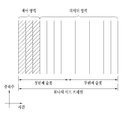
이하에서는 D2D 통신에서 사용되는 자원 구성에 대해서 설명한다. 도 6은 단말 간 통신을 위한 자원 유닛의 구성을 설명하기 위한 도면이다. Hereinafter, the resource configuration used in the D2D communication will be described. 6 is a diagram for explaining a configuration of a resource unit for inter-terminal communication.
일반적으로 자원 풀은 복수의 자원 유닛으로 구성되며 각 단말은 하나 또는 복수의 자원 유닛을 선택하여 D2D 통신을 위해 사용할 수 있다. 도 14는 자원 유닛을 구성하는 방법 중 하나를 나타내는 것으로, 전체 주파수 자원 풀이 NF개로 분할되고 전체 시간 자원이 NT개로 분할되어 총 NF*NT 개의 자원 유닛이 정의되는 경우를 나타낸다.Generally, a resource pool is composed of a plurality of resource units, and each terminal can select one or a plurality of resource units and use it for D2D communication. 14 shows a case represents one of the following methods constituting a resource unit, is divided N F dogs entire frequency resource pool is divided the total time resources dogs N T is the total N F * N T different resource units are defined.
이때, 자원 풀이 NT 서브프레임을 주기로 반복된다고 할 수 있다. 또한, 하나의 자원 유닛은 하나의 자원 풀 내에서 주기적으로 반복하여 할당될 수 있다. 예를 들어, 자원 유닛 #0, #1, ... , 및 #( NF -1)은 해당 자원 풀 내에서 소정 시간의 주기로 반복하여 할당되는 모습을 나타낸다. 즉, 자원 유닛 #0을 할당 받은 단말은 하나의 자원 풀 내에서 자원 유닛 #0으로 인덱싱 된 자원 유닛을 모두 사용할 수 있다.At this time, it can be said that the resource pool is repeated at intervals of N T subframes. Further, one resource unit may be periodically and repeatedly allocated in one resource pool. For example, the
또한, 자원 풀 내의 자원 유닛 또는 자원 풀 자체는 시간 및/또는 주파수 차원에서의 다이버시티(diversity) 효과를 얻기 위해서 하나의 논리적인 자원 유닛이 매핑되는 물리적 자원 유닛의 인덱스가 시간에 따라서 사전에 정해진 패턴으로 변화되도록 구성될 수 있다. 이러한 자원 유닛 구조에 있어서 자원 풀이란 D2D 신호를 송수신하고자 하는 단말이 D2D 신호의 송수신에 사용할 수 있는 자원 유닛의 집합을 의미할 수 있다. In addition, the resource units in the resource pool or the resource pool itself may be configured such that the index of the physical resource unit to which one logical resource unit is mapped to obtain a diversity effect at the time and / Pattern. ≪ / RTI > In this resource unit structure, a resource pool may mean a set of resource units that a terminal desiring to transmit / receive a D2D signal can use to transmit / receive a D2D signal.
본 발명의 실시예들에서 D2D 통신을 위한 자원 풀은 여러 종류로 구분될 수 있다. 먼저 각 자원 풀을 통해 전송되는 D2D 신호의 내용/종류에 따라서 구분될 수 있다. 예를 들어, D2D 신호는 스케줄링 할당(SA: Scheduling Assignment) 신호, D2D 데이터 채널 신호 및 디스커버리 채널(Discovery Channel) 신호 등으로 구분될 수 있다. In the embodiments of the present invention, resource pools for D2D communication can be classified into various kinds. First, it can be classified according to the content / type of the D2D signal transmitted through each resource pool. For example, the D2D signal may be classified into a Scheduling Assignment (SA) signal, a D2D data channel signal, and a Discovery Channel signal.
스케줄링 할당(SA) 신호는 D2D 통신을 위한 D2D 데이터 채널이 할당된 자원 위치, D2D 데이터 채널의 변/복조를 위해서 필요한 변조 및 코딩 방식(MCS: Modulation and Coding Scheme), MIMO 전송 방식 및/또는 TA(Timing Advance) 등의 정보를 포함하는 신호를 의미한다. SA 신호는 소정의 자원 유닛 상에서 독립적으로 전송되거나, 동일 자원 유닛 상에서 D2D 데이터와 함께 다중화(multiplex)되어 전송될 수 있다. SA 신호가 데이터와 다중화 되는 경우, SA 자원 풀이란 SA가 D2D 데이터와 다중화되어 전송되는 자원 유닛의 집합을 의미할 수 있다. 본 발명의 실시예들에서, SA 신호가 전송되는 자원 유닛을 SA 채널 또는 D2D 제어 채널이라 부를 수 있다. The scheduling assignment (SA) signal includes a resource location to which a D2D data channel for D2D communication is allocated, a modulation and coding scheme (MCS) required for demodulating / demodulating the D2D data channel, a MIMO transmission scheme, and / (Timing Advance), and the like. The SA signal may be transmitted independently on a predetermined resource unit, or may be multiplexed with D2D data and transmitted on the same resource unit. When the SA signal is multiplexed with the data, the SA resource pool may mean a set of resource units in which the SA is multiplexed with the D2D data and transmitted. In the embodiments of the present invention, a resource unit to which an SA signal is transmitted may be referred to as an SA channel or a D2D control channel.
D2D 데이터 채널은 단말들이 SA를 통하여 지정된 자원을 사용하여 D2D 데이터를 송수신하기 위한 자원 유닛의 집합으로 정의될 수 있다. D2D 데이터 채널은 SA 채널과 다중화될 수 있다. 또한 D2D 데이터 채널은 SA 신호 없이 D2D 데이터 신호 만이 다중화될 수 있다.The D2D data channel can be defined as a set of resource units for transmitting and receiving D2D data by using terminals and designated resources through the SA. The D2D data channel can be multiplexed with the SA channel. Also, in the D2D data channel, only the D2D data signal can be multiplexed without the SA signal.
이 때, 동일 자원 유닛 상에서 SA 신호와 D2D 데이터 채널이 함께 다중화되어 전송될 수 있는 경우에, D2D 데이터 채널을 위한 자원 풀에는 SA 신호를 제외한 형태의 D2D 데이터 채널 만이 전송되는 형태로도 구성될 수 있다. 다시 말하면 SA 자원 풀 내에의 개별 자원 유닛 상에서 SA 정보를 전송하는데 사용되었던 자원 유닛은 D2D 데이터 채널을 위한 자원 풀에서는 여전히 D2D 데이터를 전송하기 위해 사용될 수 있다.In this case, when the SA signal and the D2D data channel can be multiplexed and transmitted on the same resource unit, the resource pool for the D2D data channel may be configured to transmit only the D2D data channel except for the SA signal have. In other words, the resource unit that was used to transmit the SA information on the individual resource unit in the SA resource pool can still be used to transmit the D2D data in the resource pool for the D2D data channel.
디스커버리 채널은 D2D 통신을 수행하기 위한 단말이 자신의 식별자 등의 정보를 전송하여 인근 단말로 하여금 자신을 발견할 수 있도록 하는 신호 또는 메시지를 전송하기 위한 자원 유닛의 집합을 의미한다.The discovery channel means a set of resource units for transmitting a signal or a message for allowing a terminal for performing D2D communication to transmit information such as its identifier to discover nearby terminals.
이때, 하나의 자원 풀 내에서 SA 신호를 전송하기 위한 SA 채널, D2D 데이터를 송수신하기 위한 데이터 채널 및 디스커버리 신호를 송수신하기 위한 디스커버리 채널이 구성될 수 있다. 또는, SA 채널, D2D 데이터 채널 또는 디스커버리 채널이 각각 별도의 자원 풀로 구성될 수 있다.At this time, an SA channel for transmitting an SA signal, a data channel for transmitting and receiving D2D data, and a discovery channel for transmitting and receiving a discovery signal may be configured within one resource pool. Alternatively, the SA channel, the D2D data channel, or the discovery channel may each be configured as a separate resource pool.
또는, D2D 신호의 내용이 동일한 경우에도 D2D 신호의 송수신 속성에 따라서 상이한 자원 풀이 할당될 수 있다. Alternatively, even when the content of the D2D signal is the same, different resource pools can be allocated according to the transmission / reception property of the D2D signal.
예를 들어, 동일한 종류의 D2D 데이터 채널이나 디스커버리 채널이라 하더라도 (1) D2D 신호의 송신 타이밍 결정 방식(예를 들어, 동기 기준 신호의 수신 시점에서 송신되는지 아니면, 해당 수신 시점에서 일정한 TA를 적용하여 전송되는지)이나, (2) 자원 할당 방식(예를 들어, 개별 신호의 전송 자원을 기지국이 개별 송신 단말에게 지정해주는지 아니면 개별 송신 단말이 자원 풀 내에서 자체적으로 개별 신호 전송 자원을 선택하는지), (3) 신호 포맷(예를 들어, 각 D2D 신호가 하나의 서브프레임에서 차지하는 심볼의 개수나, 하나의 D2D 신호 전송에 사용되는 서브프레임의 개수 등), (4) 기지국으로부터의 신호 세기 및/또는 (5) D2D 단말의 송신 전력 세기 등에 따라서 상이한 자원 풀로 구성될 수 있다. For example, even in the case of a D2D data channel or a discovery channel of the same kind, (1) the transmission timing determination method of the D2D signal (for example, whether the transmission is performed at the reception timing of the synchronization reference signal or (For example, whether the base station assigns the transmission resource of the individual signal to the individual transmitting terminal or whether the individual transmitting terminal itself selects an individual signal transmission resource in the resource pool), or (2) (3) the signal format (e.g., the number of symbols each D2D signal occupies in one subframe, the number of subframes used in one D2D signal transmission, etc.), (4) Or (5) the transmission power of the D2D terminal.
본 발명의 실시예들에서는, 설명의 편의상 D2D 통신에서 기지국이 D2D 송신 단말의 자원 영역을 직접 스케줄링하는 방법을 제1모드(Mode 1)로 정의한다. 또한, D2D 전송 자원 영역이 사전에 설정되어 있거나 기지국이 전송 자원 영역을 할당하되, 단말이 해당 전송 자원 영역 중에서 D2D 통신을 위한 자원 유닛을 선택하는 방법을 제2모드(Mode 2)라 정의한다.In embodiments of the present invention, a method for directly scheduling a resource area of a D2D transmitting terminal in a D2D communication in a D2D communication is defined as a first mode (Mode 1). A second mode (Mode 2) is a method in which a D2D transmission resource region is preset or a base station allocates a transmission resource region, and a terminal selects a resource unit for D2D communication among the transmission resource regions.
D2D 디스커버리의 경우에는 사전에 설정된 자원 영역 또는 기지국이 지시한 자원 영역 중에서 단말이 D2D 디스커버리를 위한 자원 유닛을 직접 선택하는 경우는 제1타입(Type 1)이라 정의한다. 또한, 기지국이 디스커버리 채널에 대한 자원 영역을 직접 스케줄링하는 경우에는 제2타입(Type 2)이라 정의한다.In the case of D2D discovery, it is defined as a first type (Type 1) when a terminal directly selects a resource unit for D2D discovery among a preset resource region or a resource region indicated by the base station. In addition, when the base station directly schedules the resource area for the discovery channel, it is defined as a second type (Type 2).
본 발명의 실시예들에서 D2D 통신을 위한 채널들은 사이드링크(sidelink)라고 불릴 수도 있다. 이러한 경우에, SA 채널은 물리 사이드링크 제어 채널(Physical Sidelink Control Channel: PSCCH), D2D 동기 신호는 사이드링크 동기 신호(SideLink Synchronization Signal: SLSS), D2D 통신을 위한 가장 기본적인 시스템 정보를 방송하는 제어 채널을 물리 사이드링크 방송채널(Physical Sidelink Broadcast Channel: PSBCH)로 불릴 수 있다. SLSS는 다른 이름으로 PD2DSCH(Physical D2D Synchronization Channel)이라고 부를 수 있다. 또한, D2D 디스커버리 신호가 전송되기 위한 채널은 물리 사이드링크 디스커버리 채널(Physical Sidelink Discovery Channel: PSDCH)로 정의될 수 있다.In embodiments of the present invention, the channels for D2D communication may be referred to as sidelinks. In this case, the SA channel is a Physical Sidelink Control Channel (PSCCH), the D2D synchronization signal is a SideLink Synchronization Signal (SLSS), a control channel for broadcasting the most basic system information for D2D communication May be referred to as a Physical Sidelink Broadcast Channel (PSBCH). SLSS may be called PD2DSCH (Physical D2D Synchronization Channel) with a different name. In addition, a channel through which the D2D discovery signal is transmitted may be defined as a Physical Sidelink Discovery Channel (PSDCH).
LTE-A 시스템(Rel-12, 13 이상)에서는 D2D 통신 단말이 PSBCH와 SLSS와 함께 전송하거나 SLSS를 전송하도록 설정되어 있다. 또한, LTE-A 시스템은 D2D 통신에서 다른 단말과의 동기를 맞추기 위한 S-RSRP(sidelink-RSRP)를 새로이 정의하고 있다. 즉, 단말들이 D2D 통신을 하고자 할 때, S-RSRP를 측정하여 특정 값 이상이 되는 단말에 대해서만 서로 동기를 맞추고 D2D 통신을 수행할 수 있다. 이때, S-RSRP는 PSBCH 상의 DM-RS 로부터 측정될 수 있다. 다만, D2D 릴레이 동작을 위해, S-RSRP는 PSDCH 상의 DM-RS로부터 측정할 수도 있다. In the LTE-A system (Rel-12, 13 or higher), the D2D communication terminal is set to transmit with the PSBCH and the SLSS or to transmit the SLSS. In addition, the LTE-A system newly defines S-RSRP (sidelink-RSRP) for synchronizing with other terminals in D2D communication. That is, when the terminals attempt to perform D2D communication, it is possible to measure the S-RSRP and perform D2D communication only by synchronizing the terminals that are above a specific value. At this time, the S-RSRP can be measured from the DM-RS on the PSBCH. However, for D2D relay operation, S-RSRP may be measured from DM-RS on PSDCH.
또한, 커버리지 밖(out-coverage)의 단말은 SLSS 및/또는 PSBCH/PSCCH/PSSCH의 DM-RS 신호 세기의 DM-RS를 기반으로 S-RSRP 등을 측정함으로써 자신이 D2D 릴레이 동작을 수행할 동기 소스(synchronization source)가 될지 여부를 결정할 수 있다.The out-coverage terminal measures the S-RSRP based on the DM-RS of the DM-RS signal strength of the SLSS and / or the PSBCH / PSCCH / PSSCH, It can decide whether or not it will become a synchronization source.
차량간 통신에서는 아래와 같은 메시지들이 전송될 수 있다.In inter-vehicle communication, the following messages can be transmitted.
- 협동 인식 메시지(CAM; Cooperative Awareness Message): CAM 방향 및 속도 등 차량의 동적 상태 정보, 치수 등 차량 정적 데이터, 외부 빛의 상태, 경로 역사를 포함하여 기본적인 차량 정보가 포함될 수 있다. CAM 메시지의 크기는 50 내지 300 바이트 이다.- Cooperative Awareness Message (CAM): Basic vehicle information including vehicle dynamic data such as CAM direction and speed, vehicle static data such as dimensions, external light conditions, and path history can be included. The size of the CAM message is 50 to 300 bytes.
- 분산 환경 알림 메시지(DENM; Decentralized Environmental Notification Message)- Decentralized Environmental Notification Message (DENM)
CAM에서도 보안 오버헤드(security overhead)가 포함된 경우에는 그렇지 않은 경우보다 더 큰 메시지 크기를 가질 수 있다. CAM은 사전에 정해진 주기로 전송될 수 있으며, DENM은 특정 이벤트가 발생한 경우에만 전송되는 것일 수 있다.If the CAM also includes security overhead, it can have a larger message size than it would otherwise. The CAM may be transmitted in a predetermined period, and the DENM may be transmitted only when a specific event occurs.
도 7(a) 내지 7(c)는 본 발명의 일 실시예에 따른 통신 시스템을 설명하기 위한 도면이다. 7 (a) to 7 (c) are views for explaining a communication system according to an embodiment of the present invention.
본 발명에서는 단말간 통신, 특히, 차량간 통신에서 네트워크를 이용한 단말간 통신 (특히, 기지국이나 노변장치(RSU)가 단말의 신호를 중계(relay)해주는)에서 자원을 효율적으로 사용하기 위한 방법을 제안한다. In the present invention, a method for efficiently using resources in inter-terminal communication, in particular, inter-terminal communication using a network in a vehicle-to-vehicle communication (in particular, a base station or an RSU relaying a terminal's signal) I suggest.
본 발명에서는 설명의 편의상 다음과 같이 용어를 정의한다. In the present invention, the following terms are defined for convenience of explanation.
- 고정 노드(F-node): V2V (Vehicle to vehicle) 또는 V2X (Vehicle to Everything) 메시지를 전달해주는 고정된 위치의 노드. 예를 들어, 기지국이나 노변에 설치된 노변장치(RSU; roadside unit)가 고정 노드의 일 예일 수 있다. - Fixed node (F-node): A node in a fixed location that carries a Vehicle to Vehicle (V2V) or Vehicle to Everything (V2X) message. For example, a base station or a roadside unit (RSU) installed on a roadside may be an example of a fixed node.
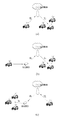
- Uu based V2V (또는 V2X): 셀룰러 네트워크 이용한 V2V 통신을 말한다. 단말은 기지국을 향해 자신의 메시지를 전송하고, 기지국은 수신 받은 메시지를 다시 하향링크 전송으로 주변 단말들에게 수신 받은 메시지를 전송한다. Uu based V2X는 도 7(a)로 표현할 수 있다.- Uu based V2V (or V2X): refers to V2V communication using a cellular network. The terminal transmits its message to the base station, and the base station transmits the received message to the neighboring terminals through the downlink transmission again. Uu based V2X can be expressed by Fig. 7 (a).
- 노변장치(RSU)를 통한 Uu 기반 V2V (또는 V2X): 도 7(b)와 같이 상향링크를 노변장치(RSU)가 중계해서 기지국으로 전달하는 동작과, 도 7(c)와 같이 하향링크를 노변장치(RSU)가 중계해주는 동작을 고려할 수 있다.- UU-based V2V (or V2X) through the RSU: As shown in FIG. 7 (b), the RSU repeats the uplink and transmits the uplink to the base station, (RSU) to the RSU.
기지국이나 노변장치(RSU)를 통한 V2V 메시지를 송수신하는 경우, 기지국이나 노변장치는 송신 단말의 위치를 정확히 알지 못할 수 있다. 이 경우, 기지국이나 노변장치는 수신 받은 패킷을 중계(relaying)해줄 때, 어떤 수신기를 대상으로 송신을 수행해야하는지 모를 수 있다. 이 경우, 기지국이나 노변장치들은 백홀 망을 통해 수신 받은 정보를 공유한 다음, 송신기가 있을 것이라고 예상되는 지역에 중첩하여 전송하는 동작이 필요할 수 있다. 이 경우, 여러 기지국이나 노변장치가 공통의 정보를 전달해야 하기 때문에, 하향링크 송신 혹은 사이드링크 송신의 부하가 심각하게 증가할 수 있다. 그러나, 만약 송신 단말의 위치를 정확하게 알 수 있다면, 해당 단말의 V2X 커버리지 안이라고 생각되는 영역에만 기지국이나 노변장치가 신호를 방송(broadcast)해줌으로써, 하향링크 또는 사이드링크의 부하를 줄일 수 있을 것이다.When a V2V message is transmitted or received through a base station or an RSU, the base station or the RS may not know the location of the transmitting terminal correctly. In this case, when the base station or the RSE relay the received packet, it may not know which receiver should perform the transmission. In this case, the base station or the sidewalk devices may need to share the information received through the backhaul network and then transmit the information overlaid on the area where the transmitter is expected to be located. In this case, the loads of the downlink transmission or the side link transmission may be seriously increased because several base stations or the sidewalk apparatus must transmit common information. However, if the location of the transmitting terminal can be accurately known, the base station or the sidewalk apparatus broadcasts signals only in the area considered as the V2X coverage of the corresponding terminal, thereby reducing the load on the downlink or the side link .
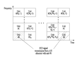
이에 대한 일 실시예로서, D2D 단말은 지리적 정보를 전송하기 위하여 D2D 단말의 지리적 정보를 측정하고, D2D 단말의 위치에 따라 결정되는 특정 자원 영역을 통하여 측정된 D2D 단말의 지리적 정보를 포함하는 메시지를 전송할 수 있다. 이러한 메시지는 safety message라고 불릴 수도 있다. 일 예로, 전송 자원은 복수 개의 자원 영역들로 분할되며, 각각의 복수 개의 자원 영역들은 하나 이상의 기준점(reference point)들 각각에 매핑될 수 있다. In one embodiment of the present invention, the D2D terminal measures geographical information of the D2D terminal to transmit geographical information and transmits a message including the geographical information of the D2D terminal measured through a specific resource area determined according to the location of the D2D terminal Lt; / RTI > These messages may be called safety messages. For example, the transmission resource may be divided into a plurality of resource regions, and each of the plurality of resource regions may be mapped to each of one or more reference points.
도 8은 본 발명의 일 실시예에 따른 기준점을 설명하기 위한 도면이다. 8 is a view for explaining reference points according to an embodiment of the present invention.
도 8을 참조하면, 특정 지역에 하나 이상의 기준점을 설정할 수 있다. 일 예로, 기준점은 기지국 또는 노변장치(RSU: Road-Side Unit)와 같은 물리적 장치의 위치일 수 있다. 다른 예로, 기준점은 좌표 정보로 구성된 가상의 지점들 또는 좌표 정보로 구성된 가상의 범위가 될 수 있다. Referring to FIG. 8, one or more reference points can be set in a specific area. As an example, the reference point may be the location of a physical device, such as a base station or a Road-Side Unit (RSU). As another example, the reference point may be a virtual range composed of virtual points or coordinate information composed of coordinate information.
일 예로, 단말의 지리적 정보는 범지구위치결정시스템(GPS; Global Positioning System)을 이용하여 측정된 단말의 좌표 정보일 수 있다. 또는, 단말의 지리적 정보는 상기 D2D 단말과 가장 가까운 기준점의 좌표 정보, 아이디, 또는 상기 기준점과의 거리 정보 중 하나 이상일 수 있다. 기존 범지구위성항법시스템(Global navigation satellite system, GNSS)에서는 단말의 위치정보가 위도는 23bit, 경도는 24bit, 고도는 15bit로 표현된다. 이러한 정보는 과도한 오버헤드가 될 수 있다. 따라서, 해당 국가, 도시, 또는 특정 지역 중심으로 간소화된 위치정보를 표현할 필요가 있다. 이러한 경우, 이를 수신한 기지국이나 노변장치(RSU)는 해당 단말이 어떤 영역에 있는지를 파악하여 수신 영역이 어디인지를 예측하고, 해당 단말의 메시지를 전달해줄 수 있다. 다시 말해, 특정 지역에 기준점을 설정하고, 각 기준점을 기준으로 위치 정보를 표시하여 기지국에 전송할 수 있다. For example, the geographical information of the terminal may be coordinate information of the terminal measured using a Global Positioning System (GPS). Alternatively, the geographical information of the terminal may be at least one of coordinate information of the reference point closest to the D2D terminal, an ID, or distance information from the reference point. In the existing global navigation satellite system (GNSS), the location information of the terminal is expressed as 23bit latitude, 24bit longitude, and 15bit altitude. This information can be excessive overhead. Therefore, it is necessary to express the simplified position information around the corresponding country, city, or specific area. In this case, the receiving base station or the RSU can determine the area of the corresponding terminal, predict where the receiving area is, and transmit the message of the corresponding terminal. In other words, a reference point can be set in a specific area, position information can be displayed based on each reference point, and transmitted to the base station.
이때, 단말들이 기지국과 공통의 기준점을 인지할 필요가 있으며, 이를 위하여 기준점에 대한 정보를 사전에 정해두거나, 네트워크에 의해 물리계층 혹은 상위계층 신호로 단말에게 시그널링 할 수 있다. 일 예로, 기준점들은 좌표 정보로 구성된 가상의 지점들 또는 좌표 정보로 구성된 가상의 범위 중 어느 하나일 수 있다. 예를 들어, 이러한 기준점에 대한 정보는 수백 km에서 수십 km단위로 설정될 수 있고, 경우에 따라서는 수십 m단위로 설정될 수도 있다. 예를 들어, 지역에 따라 기준점 간의 간격이나, 위치 정보를 시그널링하는 입도(granularity)가 변경될 수 있다. In this case, the terminals need to recognize a common reference point with the base station. For this, the base station may set information on the reference point in advance or signal the terminal to the physical layer or the higher layer signal by the network. For example, the reference points may be any of virtual points composed of coordinate information or a virtual range composed of coordinate information. For example, the information on such a reference point may be set to several hundred km to several tens km, and in some cases, to several tens of meters. For example, the spacing between reference points or the granularity for signaling location information may vary depending on the area.
일 예로, 고속도로에서는 단말의 위치정보를 나타내기 위한 기준점이 듬성듬성 있는데 반해, 도심에는 기준점이 조밀하게 구성될 수 있다. 이러한 경우에 단말은 자신의 위치를 표현하기 위해 위치 정보의 입도(granularity)를 변경할 수 있다. 이러한 입도(granularity) 정보는 사전에 정해두거나, 위치에 따라 적응적으로 결정하거나, 네트워크에 의해 단말에게 시그널링 될 수 있다. 또는, 단말이 스스로 일정 범위내의 입도(granularity)를 결정하여 네트워크 (e.g. F-node)에게 시그널링 할 수도 있다.For example, in the expressway, the reference point for indicating the location information of the terminal is sparsely populated, while the reference point in the city center is densely populated. In this case, the terminal may change the granularity of the location information to express its location. Such granularity information may be determined in advance, adaptively determined according to the location, or signaled to the terminal by the network. Alternatively, the terminal may itself determine the granularity within a certain range and signal the network (e.g., F-node).
다른 예로, 단말의 이동성이 큰 경우에는 기준점이 자주 변경될 수 있다. 이러한 경우, 단말은 자신이 가장 가까운 기준점 정보와 기준점으로부터의 자신의 위치 차이 정보를 네트워크 (e.g. F-node)로 시그널링 할 수 있다. 이 때, 기준점 위치 정보를 궤환하거나 기준점 ID (e.g. 셀 ID, RSU ID)를 궤환할 수 있다. 또한, 이러한 방법은 지역을 일부 작은 단위의 영역으로 나누고 영역에 대한 정보를 궤환하는 방법으로 해석될 수도 있다. 예를 들어, 특정 국가의 지역이 특정 위치를 중심으로 d만큼의 위도, 경도 거리단위의 사각형 영역으로 구성되어 있고, 각 영역에는 순차적으로 ID가 부여될 수 있다. 단말은 자신의 위치에 따라 영역의 ID를 궤환하는 방식으로 위치 정보를 간소화할 수 있다. 이러한 위치 정보를 보고하는 방식에서는 GNSS에서 단말의 위치를 표시하는 bit 수를 훨씬 줄일 수 있는 장점이 있다.As another example, when the mobility of the terminal is large, the reference point may be changed frequently. In this case, the terminal can signal its position difference information from the nearest reference point information and the reference point to a network (e.g., F-node). At this time, the reference point position information can be fed back or the reference point ID (e.g., cell ID, RSU ID) can be fed back. Also, this method may be interpreted as a method of dividing a region into regions of a small unit and feedbacking information about the regions. For example, a region of a specific country is constituted by a rectangular area having latitude and longitude distance units as long as d around a specific location, and IDs can be sequentially assigned to each area. The terminal can simplify the location information in such a manner that the ID of the area is fed back according to its location. This method of reporting location information has the advantage of reducing the number of bits that indicate the location of the terminal in the GNSS.
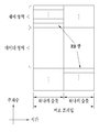
도 9는 본 발명의 일 실시예에 따른 자원 영역을 설명하기 위한 도면이다.9 is a view for explaining a resource area according to an embodiment of the present invention.
도 9를 참조하면, 전송 자원은 복수 개의 자원 영역들로 분할되며, 상기 각각의 복수 개의 자원 영역들은 하나 이상의 기준점(reference point)들 각각에 매핑될 수 있다. 일 예로, 도 9에서 나타난 바와 같이, 전송 자원은 16 개의 영역으로 분할될 수 있으며, 각 분할된 자원 영역은 각각 하나의 기준점과 일대일로 매핑될 수 있다. 이러한 다수개의 기준점은 특정 기준점으로부터 가로, 세로로 일정 거리를 떨어진 것으로 표현할 수 있다. 각 기준점을 중심으로 가장 가까운 기준점마다 자원 영역이 설정될 수 있는데, 이 때, 자원 영역과 기준점은 일대일 관계에 한정되지 않는다. 또한, 전송 자원은 전체 영역 또는 일부 영역이 분할될 수 있다.Referring to FIG. 9, a transmission resource is divided into a plurality of resource regions, and each of the plurality of resource regions may be mapped to one or more reference points. For example, as shown in FIG. 9, a transmission resource may be divided into 16 regions, and each divided resource region may be mapped to a reference point one-to-one. Such a plurality of reference points can be expressed as a certain distance from the specific reference point in the horizontal and vertical directions. A resource area may be set for each reference point closest to each reference point. In this case, the resource area and the reference point are not limited to a one-to-one relationship. Further, the transmission resource may be divided into the entire area or a part of the area.
일 예로, 기지국은 특정 자원 영역을 설정하고, 단말에게 자원 영역에 대한 정보를 전송하여 단말이 스스로 자원을 선택하여 전송할 수 있도록 할 수 있다. 이 때, 기지국은 전송 자원을 RSRP를 기준으로 분할하여 전송 자원을 설정할 수 있다. 다시 말해, 분할된 복수 개의 자원 영역들은 각각 매핑된 기준점들로부터 수신한 신호의 수신 전력이 소정의 조건을 만족하는 경우에 사용 가능한 것으로 판단하고, 해당 자원 영역을 통하여 메시지를 전송할 수 있다. For example, the base station may set a specific resource region and transmit information about the resource region to the terminal so that the terminal can select and transmit resources by itself. At this time, the base station can divide the transmission resources based on the RSRP to set transmission resources. In other words, the plurality of divided resource areas can be used when the received power of the signal received from the mapped reference points satisfies a predetermined condition, and the message can be transmitted through the corresponding resource area.
예를 들어, 단말은 해당 자원영역의 사용조건을 만족한 경우에 해당 자원 영역에서 메시지를 전송함으로써, 묵시적으로 기지국이 해당 단말이 어떤 영역에 있는지를 파악할 수 있게 된다. 이러한 동작을 위하여 기지국은 자원 영역별로 해당 자원 영역을 사용할 수 있는 RSRP 임계값의 상한/하한 값을 설정할 수 있다. 이때, 특정 자원 영역은 단순히 특정 셀의 RSRP 제한 조건만 있는 것이 아니라 인접 다른 셀의 RSRP 제한 조건이 추가로 부여될 수 있다. For example, when the terminal satisfies the use condition of the corresponding resource area, the terminal transmits the message in the corresponding resource area, so that the base station can grasp in which area the terminal is located. For this operation, the BS can set the upper / lower limit value of the RSRP threshold value that can use the corresponding resource region for each resource region. At this time, the specific resource region is not limited to the RSRP constraint of a specific cell but may be additionally given an RSRP constraint of another adjacent cell.
일 예를 들어, 셀이 A, B 두 개가 있고 두 셀의 경계에 단말들이 있다고 가정하면, 셀 A로부터의 RSRP가 일정 임계 이하이면서, 셀 B로부터의 RSRP 또한 일정 임계 이하인 단말만 사용할 수 있는 자원 영역을 네트워크가 설정할 수 있다. 그리고, 해당 조건을 만족하는 단말만이 그 자원 영역을 사용하도록 설정할 수 있다. 이러한 경우, 해당 자원 영역의 신호를 수신한 기지국은 해당 메시지를 전송한 단말 대략 어떤 위치에 있는지 파악할 수 있다. 이러한 자원 영역을 통하여 메시지를 전송하는 단말은 셀의 경계에 있다고 파악될 수 있다. 따라서, 해당 단말의 메시지는 셀 A와 B 모두에서 하향링크 전송이 수행될 수 있다. For example, assuming that there are two cells A and B and that there are terminals at the boundary between two cells, the RSRP from the cell A is less than a certain threshold, and the RSRP from the cell B is also a resource The area can be set by the network. Only the terminal satisfying the condition can be set to use the resource area. In this case, the base station receiving the signal of the corresponding resource area can know which position the terminal that transmitted the message is located. Through this resource area, the terminal transmitting the message can be recognized as being on the cell boundary. Accordingly, downlink transmission can be performed in both the cells A and B of the message of the corresponding terminal.
다른 예를 들어, 특정 셀의 RSRP가 일정 임계이상으로 설정된 자원영역이 있을 수 있다. 이 자원 영역에서 전송하는 단말들은 해당 셀의 중심에 있는 것으로 파악될 수 있다. 따라서, 해당 단말의 메시지는 단일 셀에서만 전송될 수 있다. For another example, there may be a resource region where the RSRP of a particular cell is set to a certain threshold or more. The terminals transmitting in the resource region can be regarded as being located at the center of the corresponding cell. Therefore, the message of the corresponding terminal can be transmitted only in a single cell.
다른 예로, 자원 영역을 사용하기 위한 조건으로 기지국의 RSRP 임계값을 설정하는 것과 동일한 방법으로 노변장치(RSU)의 measurement의 제한 조건(threshold)이 설정될 수 있다. 네트워크는 각 자원 영역별 RSRP 또는 RSU measurement의 제한 조건을 물리계층 혹은 상위계층 신호로 단말들에게 시그널링 하거나, 사전에 자원 영역 및 영역별 제한 조건을 특정 값으로 설정할 수 있다.As another example, a threshold of measurement of the RSU may be set in the same manner as setting the RSRP threshold of the base station as a condition for using the resource area. The network can signal RSs with constraints of RSRP or RSU measurement for each resource area to the MSs in the physical layer or higher layer signal, or can set the resource region and the constraint for each region to a specific value in advance.
일 예에 따르면, D2D 단말의 지리적 정보는 메시지의 MAC(media access control) 헤더 또는 제어 요소(control element) 중 어느 하나에 포함되어 전송될 수 있다. 단말의 지리적 정보는 단말의 위치, 속도, 또는 방향 중 적어도 하나를 포함할 수 있다. According to one example, the geographical information of the D2D terminal may be transmitted in either a media access control (MAC) header of a message or a control element. The geographical information of the terminal may include at least one of location, speed, or direction of the terminal.
종래의 CAM 메시지는 단말의 위치정보를 포함할 수 있다. 따라서, 기지국이 단말의 위치 정보를 해독할 수 있다면, 별도의 추가 동작 없이, 하향링크나 사이드링크 전송 시 해당 단말 주변의 셀들만 방송(broadcasting)을 수행하여 과도한 하향링크 또는 사이드링크 전송을 예방할 수 있다. 단, 이러한 방법은 기지국이나 노변장치(RSU)가 단말의 보안 메시지(security message)를 수신하지 못할 경우 해독이 불가능하거나, 보안 메시지를 수신할 때까지 지연이 발생할 수 있다. 따라서, 별도의 필드 (MAC header나 data영역의 일부 필드에)에 다른 단말, 기지국, 노변장치(RSU)도 security overhead 수신 없이 해독 가능한 위치정보를 명시적으로 포함하여 전송하도록 할 수 있다. 이러한 경우, 특정 단말의 신호를 여러 기지국이나 노변장치가 수신하였을 때, 해당 단말의 MAC 헤더나 특정 필드에 포함된 위치정보를 활용하여, 수신한 특정 단말의 신호를 전달(forwarding) 해야 하는지 여부를 판단할 수 있다. 이후, 이를 전달(forwarding)할 필요가 있는 경우 하향링크 또는 사이드 링크로 해당 단말의 메시지를 전송할 수 있다. A conventional CAM message may include location information of a terminal. Therefore, if the base station can decode the location information of the terminal, it can broadcast only the cells around the corresponding terminal in the downlink or side link transmission without additional operation, thereby preventing excessive downlink or side link transmission have. However, this method can not be decrypted if a base station or an RSU can not receive a security message of the terminal, or a delay may occur until a security message is received. Accordingly, another terminal, a base station, and an RSU can explicitly include detable position information without receiving security overhead in a separate field (in a MAC header or a field of a data area). In this case, when a base station or a sidetracking device receives a signal of a specific terminal, it is determined whether the signal of the specific terminal should be forwarded using the MAC header of the terminal or the location information contained in the specific field It can be judged. Thereafter, when it is necessary to forward it, the message of the corresponding terminal can be transmitted through the downlink or the side link.
다른 예를 따르면, 셀 ID 및/또는 노변장치(RSU) ID를 메시지 (e.g. V2X 메시지)의 MAC 헤더 또는 제어 요소(CE)나 메시지의 일부 영역에 포함하여 전송할 수 있다. 다시 말해, 단말이 어떤 영역에 위치하고 있는지를 판단하기 위하여 단말은 자신이 캠핑(camping)하고 있는 셀 ID나 가장 가까이에 있다고 판단되는 노변장치(RSU)의 ID를 포함하여 전송할 수 있다. 단말은 현재 가장 가까이 있는 노변장치(RSU)나 eNB의 ID를 MAC 헤더 및/또는 제어 요소나 별도의 필드에 포함하여 전송할 수 있다. 여기서 캠핑(camping) 혹은 선택하고 있다는 것은 RSRP 가 가장 좋은 셀로 간주할 수도 있고, 단말이 특정 방식을 이용하여 선택한 셀을 의미할 수도 있다. 노변장치(RSU)의 경우에는 노변장치(RSU)가 전송하는 신호를 측정하여 가장 좋은 measurement를 갖는 노변장치(RSU)를 의미하는 것일 수 있다. 이하에서, RSRP는 기지국이나 단말이 전송한 특정 참조 신호의 수신 전력을 측정한 것을 의미하며, 셀 ID와 RSRP를 전송한다는 것은 노변장치(RSU)관점에서 UE의 ID와 UE가 전송한 참조신호의 수신 전력을 전송한다는 것으로 확장될 수 있다. 본 발명에서는 ID, RSRP를 전송한다는 것은 기지국과 단말 UE 모두의 것을 포함하는 것으로 해석될 수 있다. According to another example, the cell ID and / or the RSU ID may be included in the MAC header of the message (e.g., the V2X message) or in some areas of the control element CE or message. In other words, in order to determine which area the terminal is located in, the terminal may transmit the cell ID of the camping station itself or the ID of the RSU that is determined to be closest to the camping station. The MS may transmit the ID of the nearest RSU or eNB in the MAC header and / or control element or in a separate field. Here, camping or selecting may refer to the RSRP being the best cell or the cell selected by the terminal in a particular way. In the case of an RSU, it may mean RSU having the best measurement by measuring the signal transmitted by the RSU. Hereinafter, RSRP means a measurement of the received power of a specific reference signal transmitted by a Node B or a UE. The transmission of the cell ID and the RSRP means that the ID of the UE and the reference signal transmitted from the UE It can be expanded to transmit the received power. In the present invention, transmission of ID and RSRP can be interpreted to include both the base station and the terminal UE.
또 다른 실시예를 따르면, (셀 ID 및/또는 RSU ID) + (RSRP 및/또는 RSU 참조신호 수신전력)을 메시지 (e.g. V2X 메시지)의 MAC 헤더 또는 제어 요소(CE)나 메시지의 일부 영역에 포함하여 전송할 수 있다. 다시 말해, 단말이 선택 또는 캠핑한 셀 ID만 포함하여 전송하는 것이 아니라, 각 셀 별 (또는 단말 별) 측정한 RSRP와 (RSRP가 큰 값을 기준으로 순차적으로) 상위 N개를 셀 ID (또는 단말 ID)를 함께 메시지 (또는 패킷; packet)의 별도의 필드 혹은 MAC 헤더 또는 제어 요소(CE)에 포함하여 전송할 수 있다. 이 방법을 통해 셀 경계에 있는 단말은 여러 셀의 유사한 RSRP를 전송하게 되며, 기지국이나 노변장치(RSU)는 이를 파악하여 경계에 있는 기지국이나 노변장치(RSU)가 함께 전송할 수 있게 된다. 반면, 특정 기지국 또는 특정 노변장치(RSU)의 RSRP가 다른 셀 또는 다른 노변장치(RSU)의 RSRP보다 과도하게 큰 경우에는 기지국이나 노변장치는 단말이 셀 중심에 있다고 간주할 수 있으며, 이에 따라, 인접 셀들이 메시지 전송을 수행하지 않을 수 있다. 이러한 경우, 하향링크 또는 사이드링크의 전송 오버헤드를 방지할 수 있다. 다른 예로, 셀들을 사전에 특정 순서로 정렬한 다음 RSRP가 일정수준인지 여부를 비트맵 형태로 메시지의 MAC 헤더나 또는 제어 요소(CE)나 메시지의 일부 영역에 포함하여 전송할 수 있다.According to yet another embodiment, the (Cell ID and / or RSU ID) + (RSRP and / or RSU reference signal received power) may be transmitted to the MAC header or control element CE of a message . In other words, instead of transmitting only the cell ID selected or camped by the terminal, the RSRP measured by each cell (or each terminal) and the N highest order (RSRP sequentially based on a large value) (Or terminal ID) together in a separate field of a message (or packet) or in a MAC header or control element CE. In this way, a terminal at a cell boundary transmits a similar RSRP of several cells, and a base station or an RSU can recognize the RSRP and transmit it to a boundary base station or a RSU together. On the other hand, if the RSRP of a particular base station or RSU is excessively greater than the RSRP of another cell or RSU, then the base station or the RS may consider the terminal to be at the cell center, Neighboring cells may not perform message transmission. In this case, transmission overhead of the downlink or side link can be prevented. As another example, the cells may be sorted in a specific order in advance and then transmitted in a bitmap form, including whether the RSRP is at a certain level, in the MAC header of the message or in the control element (CE) or a part of the message.
또 다른 실시예를 따르면, (RSRP가 가정 좋은 셀 ID 및/또는 RSU ID) + (이웃 셀 ID 및/또는 이웃 RSU ID)를 메시지 (e.g. V2X 메시지)의 MAC 헤더 또는 제어 요소(CE)나 메시지의 일부 영역에 포함하여 전송할 수 있다. 이를 위하여, 단말이 이동 방향에 위치하는 셀 ID를 함께 MAC 헤더 또는 제어 요소(CE)나 메시지의 특정영역에 포함하여 전송할 수 있다. 단말은 차 순위 RSRP를 가지는 셀의 셀 ID를 상위 N개까지 포함하여 전송할 수 있다. 기지국이나 노변장치(RSU)는 이를 고려하여 하향링크 또는 사이드 링크 전송을 수행할 수 있다. 기지국의 경우와 마찬가지로 RSRP가 큰 것부터 상위 N개의 주변 노변장치(RSU)의 ID를 포함하여 전송할 수도 있다.According to yet another embodiment, a message (e.g., a V2X message) MAC header or control element (CE) or message (e.g., a cell ID and / or an RSU ID) Can be included in a part of the area and transmitted. To this end, the UE may transmit the cell ID included in the movement direction together with the MAC header or the control element (CE) or a specific area of the message. The UE can transmit up to N upper cell IDs of cells having the next rank RSRP. The base station or the RSU can perform downlink or side link transmission considering this. As in the case of the base station, the ID of the upper N RSUs from the RSRP may be transmitted.
다른 실시예에 따르면, 측정된 단말의 지리적 정보를 포함하는 메시지는 특정 조건이 만족된 경우에 한하여 전송될 수 있다. 예를 들어, 특정 조건은 단말과 가장 가까운 기준점이 변경된 경우, 기준점과 특정 거리 이상 멀어진 경우, 단말이 메시지를 전송 시점의 위치에서 특정 범위 이상 이동한 경우, 또는 단말이 메시지를 전송 시점으로부터 일정 시간이 경과된 경우 중 하나 이상일 수 있다. According to another embodiment, the message including the measured geographical information of the terminal may be transmitted only when the specific condition is satisfied. For example, a specific condition may be that when the reference point closest to the terminal is changed, when the reference point is distant from the reference point by a certain distance, when the terminal moves the message beyond a specific range at the transmission timing, May be one or more of the elapsed time.
일 예로, 단말은 기준점을 중심으로 거리가 일정 이상 떨어졌을 때, 자신의 위치가 곧 다른 기준점으로 바뀔 것임을 알리기 위하여 네트워크(e.g. 고정 노드; F-node)에게 시그널링할 수도 있다. 단말은 자신의 이동경로에 따라 기준점과의 거리차이가 일정 임계 이상일 때, 위치 차이 정보 또는 임계를 넘었음을 지시하는 정보를 고정 노드(F-node)에게 보고할 수 있다. 또는 단말은 자신의 기준점이 바뀌었을 때, 이를 지시하기 위하여 고정 노드(F-node)에게 시그널링 할 수 있다.For example, the UE may signal to a network (e.g., an F-node) to notify that its location will soon be changed to another reference point when the distance is more than a predetermined distance from the reference point. When the distance difference from the reference point to the reference point is equal to or larger than a predetermined threshold according to the movement route of the mobile station, the mobile station can report the location difference information or information indicating that the mobile station has exceeded the threshold to the F-node. Alternatively, the terminal may signal to a fixed node (F-node) to indicate when its reference point has changed.
다른 예로, 단말은 기준점이 바뀌었을 때뿐만 아니라, 위치 정보의 변동이 일정 임계 이상 발생하였을 때 네트워크로 시그널링하도록 규칙이 정해질 수도 있다. 예를 들어, 단말이 매 100ms마다 메시지를 전송함에 있어서, 위치 정보의 변경이 일정 임계를 넘는 경우에만 위치 정보를 기지국이나 노변장치(RSU)가 바로 해석할 수 있는 필드에 포함하여 전송할 수 있다. 이 때, 타임 스탬프(time stamp) 정보도 함께 전송될 수 있다. 이에 따를 경우, 단말의 과도한 위치 정보 시그널링을 줄일 수 있다.As another example, the terminal may be configured to signal to the network not only when the reference point is changed, but also when the variation of the position information occurs over a certain threshold. For example, when a terminal transmits a message every 100 ms, the location information may be included in a field directly interpretable by the base station or the RSU only when the change of the location information exceeds a predetermined threshold. At this time, time stamp information may also be transmitted. Accordingly, it is possible to reduce excessive position information signaling of the terminal.
일 예로, 위에서 설명한 바와 같이, 단말이 위치 정보를 매 메시지에 포함하여 전송하는 경우 과도한 오버헤드를 발생시킬 수 있다. 따라서, 위치가 급격하게 변화하거나, 일정 시간 구간을 두고 시그널링 할 수도 있다. 이를 위하여 단말은 자신의 위치 정보를 보고할 때 언제 측정한 위치 정보인지 시간 정보 (time stamp)를 포함하여 전송할 수 있다. 이 때, 시간 정보 또한 절대 시간을 기준으로 궤환 할 경우 너무 과도한 오버헤드를 야기할 수 있다. 따라서, 오버헤드를 줄이기 위하여 특정 기준 시간을 중심으로 시간 차이 정보를 궤환할 수 있다. 예를 들어, 네트워크의 SFN (혹은 DFN)을 기준으로 현재 보고하는 위치정보의 시간 정보를 시그널링 할 수 있다.For example, as described above, excessive overhead may occur when a mobile station transmits position information in a message. Therefore, the position may change abruptly or may be signaled over a predetermined time interval. For this purpose, the terminal can transmit the time information when it reports its location information, including time information. At this time, if time information is also fed back based on absolute time, it may cause excessive overhead. Therefore, in order to reduce the overhead, the time difference information can be fed back around a specific reference time. For example, it is possible to signal time information of location information currently reporting based on SFN (or DFN) of the network.
다른 실시예에 따르면, 위에서 설명한 위치 정보는 물리계층 혹은 상위계층 신호로 단말로부터 기지국이나 노변장치(RSU)로 시그널링 될 수 있다. 단말이 어떤 채널 (물리계층, MAC header, 제어 요소(CE), 또는 RRC)을 통하여 시그널링 할 것인지, 단말이 어떤 조건에서 시그널링 하는지는 사전에 정해있거나, 네트워크가 물리계층 혹은 상위계층 신호로 단말에게 지시할 수 있다. 한편, 단말은 위치뿐만 아니라, 속도, 방향 등에 대한 정보를 물리계층 혹은 상위계층 신호로 기지국이나 RSU에 궤환할 수 있다. 이러한 정보를 통칭하여 지리적 정보(geographical information)이라고 부를 수 있다. 단말은 지리적 정보 중 어떤 정보를 어떤 상황에서 어떠한 채널로 기지국이나 RSU에게 시그널링 할 것인지를 사전에 정해져 있거나 (preconfigured), 네트워크에 의해 물리계층 혹은 상위계층 신호로 지시될 수 있다. 또한 이러한 정보 궤환은 RRC 연결된 UE들에게만 수행되는 것일 수도 있다. 또는 RRC 유휴(idle) 단말 중에서도 SIB에의해 정보 궤환 조건, 궤환 여부 등이 시그널링 될 경우, 특정 단말이 연결 모드(connected mode)로 전환하거나, 유휴 모드(idle mode)에서 Uu 링크 전송방식에 의해 기지국이나 노변장치(RSU)로 해당 정보를 시그널링 할 수 있다.According to another embodiment, the location information described above can be signaled from the terminal to the base station or the RSU with physical layer or higher layer signals. Whether a terminal signals a signal through a channel (physical layer, MAC header, control element (CE), or RRC) or a signal under which condition is determined by the terminal is determined in advance, You can tell. Meanwhile, the UE can feed back information on the location, speed, and direction as well as the physical layer or the upper layer signal to the base station or the RSU. This information collectively can be called geographical information. The terminal can pre-define (preconfigured) which channel of the geographical information the signal to be transmitted to the base station or the RSU on the certain channel under certain circumstances, and can be indicated by the network as a physical layer or an upper layer signal. This information feedback may also be performed only for RRC-connected UEs. Or an RRC idle terminal is signaled by the SIB, whether the information feedback condition, feedback or the like is signaled, the specific terminal switches to a connected mode, or in an idle mode, Or signaling the corresponding information to the RSU.
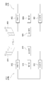
도 10은 본 발명의 실시 형태에 따른 기지국 장치 및 단말 장치의 구성을 도시한 도면이다. 10 is a diagram showing a configuration of a base station apparatus and a terminal apparatus according to an embodiment of the present invention.
도 10을 참조하여 본 발명에 따른 기지국 장치(1010)는, 수신모듈(1011), 전송모듈(1012), 프로세서(1013), 메모리(1014) 및 복수개의 안테나(1015)를 포함할 수 있다. 복수개의 안테나(1015)는 MIMO 송수신을 지원하는 기지국 장치를 의미한다. 수신모듈(1011)은 단말로부터의 상향링크 상의 각종 신호, 데이터 및 정보를 수신할 수 있다. 전송모듈(1012)은 단말로의 하향링크 상의 각종 신호, 데이터 및 정보를 전송할 수 있다. 프로세서(1013)는 기지국 장치(1010) 전반의 동작을 제어할 수 있다.10, a
본 발명의 일 실시예에 따른 기지국 장치(1010)의 프로세서(1013)는, 앞서 설명된 각 실시예들에서 필요한 사항들을 처리할 수 있다.The
기지국 장치(1010)의 프로세서(1013)는 그 외에도 기지국 장치(1010)가 수신한 정보, 외부로 전송할 정보 등을 연산 처리하는 기능을 수행하며, 메모리(1014)는 연산 처리된 정보 등을 소정시간 동안 저장할 수 있으며, 버퍼(미도시) 등의 구성요소로 대체될 수 있다. The
계속해서 도 10을 참조하면 본 발명에 따른 단말 장치(1020)는, 수신모듈(1021), 전송모듈(1022), 프로세서(1023), 메모리(1024) 및 복수개의 안테나(1025)를 포함할 수 있다. 복수개의 안테나(1025)는 MIMO 송수신을 지원하는 단말 장치를 의미한다. 수신모듈(1021)은 기지국으로부터의 하향링크 상의 각종 신호, 데이터 및 정보를 수신할 수 있다. 전송모듈(1022)은 기지국으로의 상향링크 상의 각종 신호, 데이터 및 정보를 전송할 수 있다. 프로세서(1023)는 단말 장치(1020) 전반의 동작을 제어할 수 있다.10, a
본 발명의 일 실시예에 따른 단말 장치(1020)의 프로세서(1023)는 앞서 설명된 각 실시예들에서 필요한 사항들을 처리할 수 있다.The
단말 장치(1020)의 프로세서(1023)는 그 외에도 단말 장치(1020)가 수신한 정보, 외부로 전송할 정보 등을 연산 처리하는 기능을 수행하며, 메모리(1024)는 연산 처리된 정보 등을 소정시간 동안 저장할 수 있으며, 버퍼(미도시) 등의 구성요소로 대체될 수 있다. The
위와 같은 기지국 장치 및 단말 장치의 구체적인 구성은, 전술한 본 발명의 다양한 실시예에서 설명한 사항들이 독립적으로 적용되거나 또는 2 이상의 실시예가 동시에 적용되도록 구현될 수 있으며, 중복되는 내용은 명확성을 위하여 설명을 생략한다. The specific configuration of the base station apparatus and the terminal apparatus may be implemented such that the above-described embodiments of the present invention are applied independently or two or more embodiments may be simultaneously applied. For the sake of clarity, It is omitted.
또한, 도 10에 대한 설명에 있어서 기지국 장치(1010)에 대한 설명은 하향링크 전송 주체 또는 상향링크 수신 주체로서의 중계기 장치에 대해서도 동일하게 적용될 수 있고, 단말 장치(1020)에 대한 설명은 하향링크 수신 주체 또는 상향링크 전송 주체로서의 중계기 장치에 대해서도 동일하게 적용될 수 있다.10, the description of the
상술한 본 발명의 실시예들은 다양한 수단을 통해 구현될 수 있다. 예를 들어, 본 발명의 실시예들은 하드웨어, 펌웨어(firmware), 소프트웨어 또는 그것들의 결합 등에 의해 구현될 수 있다. The above-described embodiments of the present invention can be implemented by various means. For example, embodiments of the present invention may be implemented by hardware, firmware, software, or a combination thereof.
하드웨어에 의한 구현의 경우, 본 발명의 실시예들에 따른 방법은 하나 또는 그 이상의 ASICs(Application Specific Integrated Circuits), DSPs(Digital Signal Processors), DSPDs(Digital Signal Processing Devices), PLDs(Programmable Logic Devices), FPGAs(Field Programmable Gate Arrays), 프로세서, 컨트롤러, 마이크로 컨트롤러, 마이크로 프로세서 등에 의해 구현될 수 있다.In the case of hardware implementation, the method according to embodiments of the present invention may be implemented in one or more Application Specific Integrated Circuits (ASICs), Digital Signal Processors (DSPs), Digital Signal Processing Devices (DSPDs), Programmable Logic Devices (PLDs) , FPGAs (Field Programmable Gate Arrays), processors, controllers, microcontrollers, microprocessors, and the like.
펌웨어나 소프트웨어에 의한 구현의 경우, 본 발명의 실시예들에 따른 방법은 이상에서 설명된 기능 또는 동작들을 수행하는 모듈, 절차 또는 함수 등의 형태로 구현될 수 있다. 소프트웨어 코드는 메모리 유닛에 저장되어 프로세서에 의해 구동될 수 있다. 상기 메모리 유닛은 상기 프로세서 내부 또는 외부에 위치하여, 이미 공지된 다양한 수단에 의해 상기 프로세서와 데이터를 주고 받을 수 있다.In the case of an implementation by firmware or software, the method according to embodiments of the present invention may be implemented in the form of a module, a procedure or a function for performing the functions or operations described above. The software code can be stored in a memory unit and driven by the processor. The memory unit may be located inside or outside the processor, and may exchange data with the processor by various well-known means.
상술한 바와 같이 개시된 본 발명의 바람직한 실시예들에 대한 상세한 설명은 당업자가 본 발명을 구현하고 실시할 수 있도록 제공되었다. 상기에서는 본 발명의 바람직한 실시예들을 참조하여 설명하였지만, 해당 기술 분야의 숙련된 당업자는 본 발명의 영역으로부터 벗어나지 않는 범위 내에서 본 발명을 다양하게 수정 및 변경시킬 수 있음을 이해할 수 있을 것이다. 예를 들어, 당업자는 상술한 실시예들에 기재된 각 구성을 서로 조합하는 방식으로 이용할 수 있다. 따라서, 본 발명은 여기에 나타난 실시형태들에 제한되려는 것이 아니라, 여기서 개시된 원리들 및 신규한 특징들과 일치하는 최광의 범위를 부여하려는 것이다.DETAILED DESCRIPTION OF THE PREFERRED EMBODIMENTS The foregoing description of the preferred embodiments of the invention disclosed herein has been presented to enable any person skilled in the art to make and use the present invention. While the present invention has been particularly shown and described with reference to preferred embodiments thereof, it will be understood by those skilled in the art that various changes and modifications may be made therein without departing from the spirit and scope of the invention as defined by the appended claims. For example, those skilled in the art can utilize each of the configurations described in the above-described embodiments in a manner of mutually combining them. Accordingly, the present invention is not intended to be limited to the embodiments shown herein but is to be accorded the widest scope consistent with the principles and novel features disclosed herein.
본 발명은 본 발명의 정신 및 필수적 특징을 벗어나지 않는 범위에서 다른 특정한 형태로 구체화될 수 있다. 따라서, 상기의 상세한 설명은 모든 면에서 제한적으로 해석되어서는 아니 되고 예시적인 것으로 고려되어야 한다. 본 발명의 범위는 첨부된 청구항의 합리적 해석에 의해 결정되어야 하고, 본 발명의 등가적 범위 내에서의 모든 변경은 본 발명의 범위에 포함된다. 본 발명은 여기에 나타난 실시형태들에 제한되려는 것이 아니라, 여기서 개시된 원리들 및 신규한 특징들과 일치하는 최광의 범위를 부여하려는 것이다. 또한, 특허청구범위에서 명시적인 인용 관계가 있지 않은 청구항들을 결합하여 실시예를 구성하거나 출원 후의 보정에 의해 새로운 청구항으로 포함할 수 있다.The present invention may be embodied in other specific forms without departing from the spirit or essential characteristics thereof. Accordingly, the above description should not be construed in a limiting sense in all respects and should be considered illustrative. The scope of the present invention should be determined by rational interpretation of the appended claims, and all changes within the scope of equivalents of the present invention are included in the scope of the present invention. The present invention is not intended to be limited to the embodiments shown herein but is to be accorded the widest scope consistent with the principles and novel features disclosed herein. In addition, claims that do not have an explicit citation in the claims may be combined to form an embodiment or be included in a new claim by amendment after the filing.
상술한 바와 같은 본 발명의 실시형태들은 다양한 이동통신 시스템에 적용될 수 있다.The embodiments of the present invention as described above can be applied to various mobile communication systems.
Claims (13)
상기 D2D 단말의 지리적 정보를 측정하는 단계; 및
상기 D2D 단말의 위치에 따라 결정되는 특정 자원 영역을 통하여 상기 측정된 D2D 단말의 지리적 정보를 포함하는 메시지를 전송하는 단계를 포함하는, D2D 단말이 지리적 정보를 전송하는 방법.A method for transmitting geographical information by a D2D terminal in a wireless communication system supporting D2D (Device to Device communication)
Measuring geographic information of the D2D terminal; And
And transmitting a message including the measured geographical information of the D2D terminal through a specific resource area determined according to the location of the D2D terminal.
전송 자원은 복수 개의 자원 영역들로 분할되며, 상기 각각의 복수 개의 자원 영역들은 하나 이상의 기준점(reference point)들 각각에 매핑되는, D2D 단말이 지리적 정보를 전송하는 방법.The method according to claim 1,
Wherein the transmission resource is divided into a plurality of resource regions, and each of the plurality of resource regions is mapped to one or more reference points, wherein the D2D terminal transmits geographical information.
상기 하나 이상의 기준점들은 기지국 또는 노변장치(RSU: Road-Side Unit) 중 적어도 하나이며, 상기 복수 개의 자원 영역들은 각각 매핑된 상기 하나 이상의 기준점들로부터 수신한 신호의 수신 전력이 소정의 조건을 만족하는 경우에 사용 가능한, D2D 단말이 지리적 정보를 전송하는 방법.3. The method of claim 2,
Wherein the one or more reference points are at least one of a base station and a road-side unit (RSU), and the plurality of resource areas are configured such that a received power of a signal received from the mapped one or more reference points satisfies a predetermined condition If available, a method by which the D2D terminal transmits geographic information.
상기 특정 자원 영역은 상기 사용 가능한 자원 영역들 중 하나 이상인, D2D 단말이 지리적 정보를 전송하는 방법.The method of claim 3,
Wherein the specific resource area is one or more of the available resource areas.
상기 하나 이상의 기준점들은 좌표 정보로 구성된 가상의 지점들 또는 좌표 정보로 구성된 가상의 범위 중 어느 하나인, D2D 단말이 지리적 정보를 전송하는 방법.3. The method of claim 2,
Wherein the at least one reference point is one of virtual points composed of coordinate information or a virtual range composed of coordinate information.
상기 D2D 단말의 지리적 정보는 상기 메시지의 MAC(media access control) 헤더 또는 제어 요소(control element) 중 어느 하나에 포함되는, D2D 단말이 지리적 정보를 전송하는 방법.The method according to claim 1,
Wherein the D2D terminal's geographical information is included in either a media access control (MAC) header of the message or a control element.
상기 D2D 단말의 지리적 정보는 상기 D2D 단말의 위치, 속도, 또는 방향 중 적어도 하나를 포함하는, D2D 단말이 지리적 정보를 전송하는 방법.The method according to claim 1,
Wherein the D2D terminal's geographical information comprises at least one of the location, speed, or direction of the D2D terminal.
상기 측정된 D2D 단말의 지리적 정보를 포함하는 메시지는 특정 조건이 만족된 경우에 전송되는, D2D 단말이 지리적 정보를 전송하는 방법.The method according to claim 1,
Wherein the measured D2D terminal's geographic information is transmitted when a specific condition is satisfied, wherein the D2D terminal transmits the geographical information.
상기 특정 조건은 상기 D2D 단말과 가장 가까운 기준점이 변경된 경우, 상기 기준점과 특정 거리 이상 멀어진 경우, 단말이 상기 메시지를 전송 시점의 위치에서 특정 범위 이상 이동한 경우, 또는 단말이 상기 메시지를 전송 시점으로부터 일정 시간이 경과된 경우 중 하나 이상인, D2D 단말이 지리적 정보를 전송하는 방법.9. The method of claim 8,
When the reference point closest to the D2D terminal is changed, the specific condition is more than a specific distance from the reference point, or when the terminal moves the message at a position of the transmission point by a certain range or more, Wherein the D2D terminal transmits one or more of the following conditions: a predetermined time elapses;
상기 D2D 단말의 지리적 정보는 범지구위치결정시스템(GPS; Global Positioning System)을 이용하여 측정된 단말의 좌표 정보인, D2D 단말이 지리적 정보를 전송하는 방법.The method according to claim 1,
Wherein the geographical information of the D2D terminal is coordinate information of a terminal measured using a Global Positioning System (GPS), wherein the D2D terminal transmits geographical information.
상기 D2D 단말의 지리적 정보는 상기 D2D 단말과 가장 가까운 기준점의 좌표 정보, 아이디, 또는 상기 기준점과의 거리 정보 중 하나 이상인, D2D 단말이 지리적 정보를 전송하는 방법.The method according to claim 1,
Wherein the geographical information of the D2D terminal is at least one of coordinate information of the reference point closest to the D2D terminal, ID, or distance information with respect to the reference point.
상기 D2D 단말의 지리적 정보는 타임 스탬프(time stamp)를 포함하는, D2D 단말이 지리적 정보를 전송하는 방법.The method according to claim 1,
Wherein the geographic information of the D2D terminal includes a time stamp.
송신 모듈; 및
상기 송신 모듈과 연결된 프로세서를 포함하며,
상기 프로세서는 상기 D2D 단말의 지리적 정보를 측정하고,
상기 D2D 단말의 위치에 따라 결정되는 특정 자원 영역을 통하여 상기 측정된 D2D 단말의 지리적 정보를 포함하는 메시지를 상기 송신 모듈을 통하여 전송하도록 구성된 지리적 정보를 전송하는 D2D 단말.A D2D terminal for transmitting geographical information in a wireless communication system supporting device-to-device communication (D2D)
Transmitting module; And
And a processor coupled to the transmitting module,
The processor measures geographical information of the D2D terminal,
Wherein the D2D terminal transmits geographical information configured to transmit, through the transmission module, a message including the measured geographical information of the D2D terminal through a specific resource area determined according to the location of the D2D terminal.
Applications Claiming Priority (7)
| Application Number | Priority Date | Filing Date | Title |
|---|---|---|---|
| US201662278982P | 2016-01-14 | 2016-01-14 | |
| US62/278,982 | 2016-01-14 | ||
| US201662296094P | 2016-02-17 | 2016-02-17 | |
| US62/296,094 | 2016-02-17 | ||
| US201662335700P | 2016-05-13 | 2016-05-13 | |
| US62/335,700 | 2016-05-13 | ||
| PCT/KR2017/000486 WO2017123054A1 (en) | 2016-01-14 | 2017-01-13 | Device and method for transmitting geographical information by d2d terminal in wireless communication system |
Publications (2)
| Publication Number | Publication Date |
|---|---|
| KR20180098413A true KR20180098413A (en) | 2018-09-03 |
| KR102109410B1 KR102109410B1 (en) | 2020-05-12 |
Family
ID=59311212
Family Applications (1)
| Application Number | Title | Priority Date | Filing Date |
|---|---|---|---|
| KR1020187023359A Active KR102109410B1 (en) | 2016-01-14 | 2017-01-13 | Apparatus and method for transmitting geographical information by D2D terminal in wireless communication system |
Country Status (4)
| Country | Link |
|---|---|
| US (1) | US20190021040A1 (en) |
| EP (1) | EP3404939A4 (en) |
| KR (1) | KR102109410B1 (en) |
| WO (1) | WO2017123054A1 (en) |
Cited By (2)
| Publication number | Priority date | Publication date | Assignee | Title |
|---|---|---|---|---|
| WO2021006473A1 (en) * | 2019-07-05 | 2021-01-14 | 현대자동차주식회사 | Resource allocation method in sidelink communication |
| KR20220024126A (en) * | 2019-06-25 | 2022-03-03 | 퀄컴 인코포레이티드 | Collision avoidance and implicit location encoding in vehicle-to-pedestrian networks |
Families Citing this family (9)
| Publication number | Priority date | Publication date | Assignee | Title |
|---|---|---|---|---|
| WO2018000263A1 (en) * | 2016-06-29 | 2018-01-04 | 广东欧珀移动通信有限公司 | Communication method, forwarding device, and terminal device |
| US10820303B2 (en) * | 2016-11-29 | 2020-10-27 | Lg Electronics Inc. | Resource allocation method for V2X communication in wireless communication system and device therefor |
| US10779192B2 (en) * | 2017-08-01 | 2020-09-15 | Htc Corporation | Method of handling carrier aggregation and related communication device |
| CN111279763B (en) * | 2017-10-27 | 2022-05-24 | Lg电子株式会社 | Method and apparatus for terminal receiving side link signal in wireless communication system supporting side link |
| JP6957556B2 (en) * | 2019-05-16 | 2021-11-02 | ソフトバンク株式会社 | Communication terminal devices, mobiles, communication systems, communication methods and programs |
| US11778435B2 (en) | 2021-03-04 | 2023-10-03 | Qualcomm Incorporated | Sidelink assisted cellular operation optimization |
| US11800581B2 (en) | 2021-03-04 | 2023-10-24 | Qualcomm Incorporated | Techniques for sidelink assisted device association |
| US11825440B2 (en) * | 2021-03-04 | 2023-11-21 | Qualcomm Incorporated | Vehicular and cellular wireless device colocation using uplink communications |
| CN115472004A (en) * | 2022-08-04 | 2022-12-13 | 阿波罗智联(北京)科技有限公司 | Method and device for associating road side point location with vehicle driving behavior and storage medium |
Citations (1)
| Publication number | Priority date | Publication date | Assignee | Title |
|---|---|---|---|---|
| KR20150002711A (en) * | 2012-05-11 | 2015-01-07 | 인텔 코오퍼레이션 | Determining proximity of user equipment for device-to-device communication |
Family Cites Families (25)
| Publication number | Priority date | Publication date | Assignee | Title |
|---|---|---|---|---|
| CA2403737C (en) * | 2000-03-21 | 2012-09-25 | Ted R. Rittmaster | System and process for distribution of information on a communication network |
| DE10316063A1 (en) * | 2003-04-08 | 2004-10-28 | O2 (Germany) Gmbh & Co. Ohg | Communication system for mobile radio with at least one subscriber area located in an overall area |
| US20050221813A1 (en) * | 2004-04-05 | 2005-10-06 | Jarno Rajahalme | System and method for initiating auxiliary communication interfaces via a primary communication interface |
| US7797108B2 (en) * | 2006-10-19 | 2010-09-14 | Gm Global Technology Operations, Inc. | Collision avoidance system and method of aiding rearward vehicular motion |
| JP5440601B2 (en) * | 2009-04-01 | 2014-03-12 | 富士通株式会社 | Mobile station communication device, communication system between mobile stations, and communication method between mobile stations |
| US8884817B2 (en) * | 2009-12-31 | 2014-11-11 | CSR Technology Holdings Inc. | GPS with aiding from ad-hoc peer-to-peer bluetooth networks |
| US8588803B2 (en) * | 2010-06-18 | 2013-11-19 | Nokia Corporation | Method and apparatus for resource scheduling for network controlled D2D communications |
| US20130051277A1 (en) * | 2011-08-30 | 2013-02-28 | Renesas Mobile Corporation | Method and apparatus for allocating resources for device-to-device discovery |
| US9883324B2 (en) * | 2011-12-20 | 2018-01-30 | Telefonaktiebolaget Lm Ericsson (Publ) | Methods and devices for sending and receiving location information for wireless devices |
| US9036546B2 (en) * | 2012-01-04 | 2015-05-19 | Futurewei Technologies, Inc. | System and method for device discovery for device-to-device communication in a cellular network |
| US8768876B2 (en) * | 2012-02-24 | 2014-07-01 | Placed, Inc. | Inference pipeline system and method |
| US9554408B2 (en) * | 2012-05-11 | 2017-01-24 | Kyocera Corporation | Device discovery management using peer device relationships for device-to-device (D2D) communication |
| US10602452B2 (en) * | 2012-11-20 | 2020-03-24 | Huawei Technologies Co., Ltd. | System and method for device-to-device operation in a cellular communications system |
| CN104144437A (en) * | 2013-05-08 | 2014-11-12 | 中兴通讯股份有限公司 | Device to device measurement processing method and device |
| US9357534B2 (en) * | 2013-08-09 | 2016-05-31 | Qualcomm Incorporated | Method and apparatus for location aided high frequency operations |
| KR101794689B1 (en) * | 2013-11-07 | 2017-11-07 | 한국전자통신연구원 | Network assistance method, apparatus, and terminal for D2D communication |
| KR102079553B1 (en) * | 2014-03-11 | 2020-04-07 | 삼성전자주식회사 | A method and apparatus for controlling interference of device to device communication |
| US20150289127A1 (en) * | 2014-04-02 | 2015-10-08 | Innovative Sonic Corporation | Method and apparatus for providing proximity information in a wireless communication system |
| KR101806903B1 (en) * | 2014-04-28 | 2017-12-08 | 인텔 아이피 코포레이션 | Method, apparatus and system for measuring a position of a user equipment in a wireless network |
| KR101646433B1 (en) * | 2014-06-11 | 2016-08-08 | 숭실대학교산학협력단 | D2D communication and Method for frequency resource allocation based on location using the same |
| EP3187015A4 (en) * | 2014-09-03 | 2017-09-20 | Huawei Technologies Co., Ltd. | System and method for d2d resource allocation |
| JP2016116205A (en) * | 2014-12-18 | 2016-06-23 | 富士通株式会社 | Positional information management unit, mobile apparatus and radio communication system |
| US20160196574A1 (en) * | 2015-01-02 | 2016-07-07 | Qualcomm Incorporated | Discovery and Mobile device Characteristics based Advertising and Billing Framework |
| US10375722B2 (en) * | 2015-05-14 | 2019-08-06 | Intel Corporation | Reduction of concurrent signaling in a relay user equipment (UE) |
| US10645549B2 (en) * | 2015-06-24 | 2020-05-05 | Intel IP Corporation | Enhanced support vehicle-to-anything (V2X) communication |
-
2017
- 2017-01-13 KR KR1020187023359A patent/KR102109410B1/en active Active
- 2017-01-13 EP EP17738683.6A patent/EP3404939A4/en active Pending
- 2017-01-13 US US16/070,161 patent/US20190021040A1/en not_active Abandoned
- 2017-01-13 WO PCT/KR2017/000486 patent/WO2017123054A1/en not_active Ceased
Patent Citations (1)
| Publication number | Priority date | Publication date | Assignee | Title |
|---|---|---|---|---|
| KR20150002711A (en) * | 2012-05-11 | 2015-01-07 | 인텔 코오퍼레이션 | Determining proximity of user equipment for device-to-device communication |
Cited By (3)
| Publication number | Priority date | Publication date | Assignee | Title |
|---|---|---|---|---|
| KR20220024126A (en) * | 2019-06-25 | 2022-03-03 | 퀄컴 인코포레이티드 | Collision avoidance and implicit location encoding in vehicle-to-pedestrian networks |
| WO2021006473A1 (en) * | 2019-07-05 | 2021-01-14 | 현대자동차주식회사 | Resource allocation method in sidelink communication |
| US12108421B2 (en) | 2019-07-05 | 2024-10-01 | Hyundai Motor Company | Resource allocation method in sidelink communication |
Also Published As
| Publication number | Publication date |
|---|---|
| KR102109410B1 (en) | 2020-05-12 |
| EP3404939A4 (en) | 2019-08-14 |
| US20190021040A1 (en) | 2019-01-17 |
| EP3404939A1 (en) | 2018-11-21 |
| WO2017123054A1 (en) | 2017-07-20 |
Similar Documents
| Publication | Publication Date | Title |
|---|---|---|
| US20220141870A1 (en) | Method and apparatus for selecting resource and transmitting pssch in wireless communication system | |
| KR102109410B1 (en) | Apparatus and method for transmitting geographical information by D2D terminal in wireless communication system | |
| KR102281350B1 (en) | Method and device for selecting resource and transmitting pssch in wireless communication system | |
| US10827500B2 (en) | Method and device for transmitting and receiving, by V2X terminal, signal in wireless communication system | |
| KR102360337B1 (en) | Method and apparatus for performing relay communication based on counter information in a wireless communication system | |
| US11191047B2 (en) | Method and apparatus for allowing user equipment to transmit and receive synchronization signal in plurality of component carriers in wireless communication system | |
| US11032789B2 (en) | Method and apparatus for calculating ranging information by terminal in wireless communication system supporting device to device communication | |
| JP6921211B2 (en) | In a wireless communication system, a method and device in which a terminal measures CR and transmits it. | |
| KR102210799B1 (en) | D2D signal transmission method and apparatus applying offset in wireless communication system | |
| US20190245592A1 (en) | Method for performing beam search or beam transmission in wireless communication system | |
| KR20190034668A (en) | How a terminal transmits data to another terminal in a wireless communication system | |
| KR102450886B1 (en) | Method and apparatus for resource selection and data transmission through measurement of a terminal in a wireless communication system | |
| US20200383094A1 (en) | Method and apparatus for transmitting sidelink signal in wireless communication system | |
| KR20170027736A (en) | Method and device for measurement by device-to-device terminal in wireless communication system | |
| JP7263311B2 (en) | Method and apparatus for transmitting feedback from a terminal that has received a signal from another terminal in a wireless communication system | |
| KR102426304B1 (en) | Signal transmission/reception method related to platoon communication in a wireless communication system | |
| US11102749B2 (en) | Method and apparatus for acquiring ranging information by terminal in wireless communication system supporting device to device communication | |
| KR20200028017A (en) | Method and apparatus for terminal to select resource and transmit signal in wireless communication system | |
| KR20200003204A (en) | Method for selecting a transmission resource for a transport block in a wireless communication system and apparatus therefor | |
| US20210160819A1 (en) | Method by which terminal simultaneously transmits messages in at least two carriers in wireless communication system supporting device to device communication, and apparatus therefor | |
| US11343770B2 (en) | Method and device for receiving signal through T-RPT in wireless communication system | |
| US11588589B2 (en) | Method for performing sidelink communication on basis of polar code and device therefor | |
| KR102662313B1 (en) | Method and device for a terminal to select resources and transmit signals on multiple CCs in a wireless communication system |
Legal Events
| Date | Code | Title | Description |
|---|---|---|---|
| PA0105 | International application |
Patent event date: 20180813 Patent event code: PA01051R01D Comment text: International Patent Application |
|
| PG1501 | Laying open of application | ||
| PA0201 | Request for examination |
Patent event code: PA02012R01D Patent event date: 20180913 Comment text: Request for Examination of Application |
|
| E902 | Notification of reason for refusal | ||
| PE0902 | Notice of grounds for rejection |
Comment text: Notification of reason for refusal Patent event date: 20190419 Patent event code: PE09021S01D |
|
| E701 | Decision to grant or registration of patent right | ||
| PE0701 | Decision of registration |
Patent event code: PE07011S01D Comment text: Decision to Grant Registration Patent event date: 20200205 |
|
| GRNT | Written decision to grant | ||
| PR0701 | Registration of establishment |
Comment text: Registration of Establishment Patent event date: 20200506 Patent event code: PR07011E01D |
|
| PR1002 | Payment of registration fee |
Payment date: 20200507 End annual number: 3 Start annual number: 1 |
|
| PG1601 | Publication of registration | ||
| PR1001 | Payment of annual fee |
Payment date: 20240409 Start annual number: 5 End annual number: 5 |
|
| PR1001 | Payment of annual fee |
Payment date: 20250409 Start annual number: 6 End annual number: 6 |