KR20180098405A - Method and apparatus for transmitting and receiving an uplink acknowledgment signal in a wireless LAN system - Google Patents
Method and apparatus for transmitting and receiving an uplink acknowledgment signal in a wireless LAN system Download PDFInfo
- Publication number
- KR20180098405A KR20180098405A KR1020187022689A KR20187022689A KR20180098405A KR 20180098405 A KR20180098405 A KR 20180098405A KR 1020187022689 A KR1020187022689 A KR 1020187022689A KR 20187022689 A KR20187022689 A KR 20187022689A KR 20180098405 A KR20180098405 A KR 20180098405A
- Authority
- KR
- South Korea
- Prior art keywords
- ppdu
- information
- uplink
- sta
- downlink
- Prior art date
- Legal status (The legal status is an assumption and is not a legal conclusion. Google has not performed a legal analysis and makes no representation as to the accuracy of the status listed.)
- Granted
Links
- 238000000034 method Methods 0.000 title claims abstract description 38
- 230000005540 biological transmission Effects 0.000 claims description 50
- 230000009977 dual effect Effects 0.000 claims description 6
- 238000012545 processing Methods 0.000 claims description 5
- 125000004122 cyclic group Chemical group 0.000 claims description 3
- 239000013256 coordination polymer Substances 0.000 description 20
- 238000010586 diagram Methods 0.000 description 17
- 230000011664 signaling Effects 0.000 description 13
- 230000004044 response Effects 0.000 description 11
- 238000004891 communication Methods 0.000 description 5
- 230000015654 memory Effects 0.000 description 4
- ATRSAWXXYCBXLI-UHFFFAOYSA-N 1-(3-bromophenyl)propan-2-amine Chemical compound CC(N)CC1=CC=CC(Br)=C1 ATRSAWXXYCBXLI-UHFFFAOYSA-N 0.000 description 3
- 230000003111 delayed effect Effects 0.000 description 3
- 101100161473 Arabidopsis thaliana ABCB25 gene Proteins 0.000 description 2
- 101100395869 Escherichia coli sta3 gene Proteins 0.000 description 2
- 101100096893 Mus musculus Sult2a1 gene Proteins 0.000 description 2
- 101150081243 STA1 gene Proteins 0.000 description 2
- 230000000694 effects Effects 0.000 description 2
- 238000012986 modification Methods 0.000 description 2
- 230000004048 modification Effects 0.000 description 2
- 238000012552 review Methods 0.000 description 2
- 230000006978 adaptation Effects 0.000 description 1
- 230000015556 catabolic process Effects 0.000 description 1
- 238000006731 degradation reaction Methods 0.000 description 1
- 230000001934 delay Effects 0.000 description 1
- 238000005516 engineering process Methods 0.000 description 1
- 230000001151 other effect Effects 0.000 description 1
Images


Classifications
-
- H—ELECTRICITY
- H04—ELECTRIC COMMUNICATION TECHNIQUE
- H04L—TRANSMISSION OF DIGITAL INFORMATION, e.g. TELEGRAPHIC COMMUNICATION
- H04L1/00—Arrangements for detecting or preventing errors in the information received
- H04L1/0001—Systems modifying transmission characteristics according to link quality, e.g. power backoff
- H04L1/0006—Systems modifying transmission characteristics according to link quality, e.g. power backoff by adapting the transmission format
-
- H—ELECTRICITY
- H04—ELECTRIC COMMUNICATION TECHNIQUE
- H04L—TRANSMISSION OF DIGITAL INFORMATION, e.g. TELEGRAPHIC COMMUNICATION
- H04L1/00—Arrangements for detecting or preventing errors in the information received
-
- H—ELECTRICITY
- H04—ELECTRIC COMMUNICATION TECHNIQUE
- H04L—TRANSMISSION OF DIGITAL INFORMATION, e.g. TELEGRAPHIC COMMUNICATION
- H04L1/00—Arrangements for detecting or preventing errors in the information received
- H04L1/0001—Systems modifying transmission characteristics according to link quality, e.g. power backoff
- H04L1/0006—Systems modifying transmission characteristics according to link quality, e.g. power backoff by adapting the transmission format
- H04L1/0007—Systems modifying transmission characteristics according to link quality, e.g. power backoff by adapting the transmission format by modifying the frame length
-
- H—ELECTRICITY
- H04—ELECTRIC COMMUNICATION TECHNIQUE
- H04L—TRANSMISSION OF DIGITAL INFORMATION, e.g. TELEGRAPHIC COMMUNICATION
- H04L1/00—Arrangements for detecting or preventing errors in the information received
- H04L1/0001—Systems modifying transmission characteristics according to link quality, e.g. power backoff
- H04L1/0023—Systems modifying transmission characteristics according to link quality, e.g. power backoff characterised by the signalling
- H04L1/0025—Transmission of mode-switching indication
-
- H—ELECTRICITY
- H04—ELECTRIC COMMUNICATION TECHNIQUE
- H04L—TRANSMISSION OF DIGITAL INFORMATION, e.g. TELEGRAPHIC COMMUNICATION
- H04L1/00—Arrangements for detecting or preventing errors in the information received
- H04L1/12—Arrangements for detecting or preventing errors in the information received by using return channel
- H04L1/16—Arrangements for detecting or preventing errors in the information received by using return channel in which the return channel carries supervisory signals, e.g. repetition request signals
- H04L1/1607—Details of the supervisory signal
- H04L1/1614—Details of the supervisory signal using bitmaps
-
- H—ELECTRICITY
- H04—ELECTRIC COMMUNICATION TECHNIQUE
- H04L—TRANSMISSION OF DIGITAL INFORMATION, e.g. TELEGRAPHIC COMMUNICATION
- H04L1/00—Arrangements for detecting or preventing errors in the information received
- H04L1/12—Arrangements for detecting or preventing errors in the information received by using return channel
- H04L1/16—Arrangements for detecting or preventing errors in the information received by using return channel in which the return channel carries supervisory signals, e.g. repetition request signals
- H04L1/18—Automatic repetition systems, e.g. Van Duuren systems
- H04L1/1829—Arrangements specially adapted for the receiver end
- H04L1/1861—Physical mapping arrangements
-
- H—ELECTRICITY
- H04—ELECTRIC COMMUNICATION TECHNIQUE
- H04L—TRANSMISSION OF DIGITAL INFORMATION, e.g. TELEGRAPHIC COMMUNICATION
- H04L1/00—Arrangements for detecting or preventing errors in the information received
- H04L1/12—Arrangements for detecting or preventing errors in the information received by using return channel
- H04L1/16—Arrangements for detecting or preventing errors in the information received by using return channel in which the return channel carries supervisory signals, e.g. repetition request signals
- H04L1/18—Automatic repetition systems, e.g. Van Duuren systems
- H04L1/1867—Arrangements specially adapted for the transmitter end
- H04L1/1896—ARQ related signaling
-
- H—ELECTRICITY
- H04—ELECTRIC COMMUNICATION TECHNIQUE
- H04L—TRANSMISSION OF DIGITAL INFORMATION, e.g. TELEGRAPHIC COMMUNICATION
- H04L27/00—Modulated-carrier systems
- H04L27/26—Systems using multi-frequency codes
-
- H—ELECTRICITY
- H04—ELECTRIC COMMUNICATION TECHNIQUE
- H04L—TRANSMISSION OF DIGITAL INFORMATION, e.g. TELEGRAPHIC COMMUNICATION
- H04L27/00—Modulated-carrier systems
- H04L27/26—Systems using multi-frequency codes
- H04L27/2601—Multicarrier modulation systems
- H04L27/2602—Signal structure
-
- H—ELECTRICITY
- H04—ELECTRIC COMMUNICATION TECHNIQUE
- H04L—TRANSMISSION OF DIGITAL INFORMATION, e.g. TELEGRAPHIC COMMUNICATION
- H04L27/00—Modulated-carrier systems
- H04L27/26—Systems using multi-frequency codes
- H04L27/2601—Multicarrier modulation systems
- H04L27/2602—Signal structure
- H04L27/2605—Symbol extensions, e.g. Zero Tail, Unique Word [UW]
- H04L27/2607—Cyclic extensions
-
- H—ELECTRICITY
- H04—ELECTRIC COMMUNICATION TECHNIQUE
- H04L—TRANSMISSION OF DIGITAL INFORMATION, e.g. TELEGRAPHIC COMMUNICATION
- H04L27/00—Modulated-carrier systems
- H04L27/26—Systems using multi-frequency codes
- H04L27/2601—Multicarrier modulation systems
- H04L27/2626—Arrangements specific to the transmitter only
- H04L27/2646—Arrangements specific to the transmitter only using feedback from receiver for adjusting OFDM transmission parameters, e.g. transmission timing or guard interval length
-
- H—ELECTRICITY
- H04—ELECTRIC COMMUNICATION TECHNIQUE
- H04L—TRANSMISSION OF DIGITAL INFORMATION, e.g. TELEGRAPHIC COMMUNICATION
- H04L5/00—Arrangements affording multiple use of the transmission path
- H04L5/0001—Arrangements for dividing the transmission path
- H04L5/0014—Three-dimensional division
- H04L5/0023—Time-frequency-space
-
- H—ELECTRICITY
- H04—ELECTRIC COMMUNICATION TECHNIQUE
- H04L—TRANSMISSION OF DIGITAL INFORMATION, e.g. TELEGRAPHIC COMMUNICATION
- H04L5/00—Arrangements affording multiple use of the transmission path
- H04L5/003—Arrangements for allocating sub-channels of the transmission path
- H04L5/0053—Allocation of signalling, i.e. of overhead other than pilot signals
- H04L5/0055—Physical resource allocation for ACK/NACK
-
- H—ELECTRICITY
- H04—ELECTRIC COMMUNICATION TECHNIQUE
- H04L—TRANSMISSION OF DIGITAL INFORMATION, e.g. TELEGRAPHIC COMMUNICATION
- H04L5/00—Arrangements affording multiple use of the transmission path
- H04L5/0091—Signalling for the administration of the divided path, e.g. signalling of configuration information
- H04L5/0092—Indication of how the channel is divided
-
- H—ELECTRICITY
- H04—ELECTRIC COMMUNICATION TECHNIQUE
- H04W—WIRELESS COMMUNICATION NETWORKS
- H04W72/00—Local resource management
- H04W72/20—Control channels or signalling for resource management
- H04W72/21—Control channels or signalling for resource management in the uplink direction of a wireless link, i.e. towards the network
-
- H—ELECTRICITY
- H04—ELECTRIC COMMUNICATION TECHNIQUE
- H04W—WIRELESS COMMUNICATION NETWORKS
- H04W72/00—Local resource management
- H04W72/20—Control channels or signalling for resource management
- H04W72/23—Control channels or signalling for resource management in the downlink direction of a wireless link, i.e. towards a terminal
-
- H—ELECTRICITY
- H04—ELECTRIC COMMUNICATION TECHNIQUE
- H04W—WIRELESS COMMUNICATION NETWORKS
- H04W84/00—Network topologies
- H04W84/02—Hierarchically pre-organised networks, e.g. paging networks, cellular networks, WLAN [Wireless Local Area Network] or WLL [Wireless Local Loop]
- H04W84/10—Small scale networks; Flat hierarchical networks
- H04W84/12—WLAN [Wireless Local Area Networks]
-
- H—ELECTRICITY
- H04—ELECTRIC COMMUNICATION TECHNIQUE
- H04B—TRANSMISSION
- H04B7/00—Radio transmission systems, i.e. using radiation field
- H04B7/02—Diversity systems; Multi-antenna system, i.e. transmission or reception using multiple antennas
- H04B7/04—Diversity systems; Multi-antenna system, i.e. transmission or reception using multiple antennas using two or more spaced independent antennas
- H04B7/0413—MIMO systems
- H04B7/0452—Multi-user MIMO systems
-
- H—ELECTRICITY
- H04—ELECTRIC COMMUNICATION TECHNIQUE
- H04L—TRANSMISSION OF DIGITAL INFORMATION, e.g. TELEGRAPHIC COMMUNICATION
- H04L1/00—Arrangements for detecting or preventing errors in the information received
- H04L1/0001—Systems modifying transmission characteristics according to link quality, e.g. power backoff
- H04L1/0002—Systems modifying transmission characteristics according to link quality, e.g. power backoff by adapting the transmission rate
- H04L1/0003—Systems modifying transmission characteristics according to link quality, e.g. power backoff by adapting the transmission rate by switching between different modulation schemes
-
- H—ELECTRICITY
- H04—ELECTRIC COMMUNICATION TECHNIQUE
- H04L—TRANSMISSION OF DIGITAL INFORMATION, e.g. TELEGRAPHIC COMMUNICATION
- H04L1/00—Arrangements for detecting or preventing errors in the information received
- H04L1/12—Arrangements for detecting or preventing errors in the information received by using return channel
- H04L2001/125—Arrangements for preventing errors in the return channel
Landscapes
- Engineering & Computer Science (AREA)
- Signal Processing (AREA)
- Computer Networks & Wireless Communication (AREA)
- Quality & Reliability (AREA)
- Mobile Radio Communication Systems (AREA)
Abstract
무선랜 시스템에서 스테이션(STA)이 하향링크 데이터에 대한 확인응답 신호를 전송하는 방법을 개시한다. 이를 위해 STA은 상향링크 스케줄링 정보를 포함하는 제어 정보 서브필드, 및 하향링크 데이터를 포함하는 하향링크 PPDU(Physical Protocol Data Unit)를 AP(Access Point)로부터 수신하고, 상기 상향링크 스케줄링 정보에 따라 상기 하향링크 데이터에 대한 확인응답 신호를 포함하는 상향링크 PPDU를 상기 AP에 전송한다. 이때, 상기 제어 정보 서브필드는, 상기 상향링크 PPDU의 길이 정보, 상기 상향링크 PPDU에 대한 RU(Resource Unit) 할당 정보, 상기 상향링크 PPDU에 대한 상향링크 MCS 정보, 상기 AP의 전송 전력, 및 상기 AP의 타겟 RSSI(Target receive signal strength indicator) 정보를 포함한다.A method for transmitting an acknowledgment signal for downlink data by a station (STA) in a wireless LAN system is disclosed. To this end, the STA receives a control information subfield including uplink scheduling information and a physical protocol data unit (PPDU) including downlink data from an access point (AP) And transmits an uplink PPDU including an acknowledgment signal for downlink data to the AP. In this case, the control information subfield may include at least one of length information of the uplink PPDU, RU (Resource Unit) allocation information for the uplink PPDU, uplink MCS information for the uplink PPDU, Target RSSI (target receive signal strength indicator) information of the AP.
Description
본 문서는 무선랜 시스템에서 상향링크 확인응답 신호 송수신에 대한 것으로서, 보다 상세하게는 하향링크 다중 사용자 데이터에 대한 확인응답 신호를 효율적으로 송수신하기 위한 방법 및 이를 위한 장치에 대한 것이다.The present invention relates to a method for transmitting / receiving an acknowledgment signal for downlink multi-user data, and more particularly, to a method and apparatus for efficiently transmitting / receiving an acknowledgment signal for downlink multi-user data.
이하에서 제안하는 확인응답 신호 송수신 방법은 다양한 무선 통신에 적용될 수 있으나, 이하에서는 본 발명이 적용될 수 있는 시스템의 일례로서 무선랜(wireless local area network, WLAN) 시스템에 대해 설명한다.Hereinafter, a wireless local area network (WLAN) system will be described as an example of a system to which the present invention can be applied.
무선랜 기술에 대한 표준은 IEEE(Institute of Electrical and Electronics Engineers) 802.11 표준으로서 개발되고 있다. IEEE 802.11a 및 b는 2.4. GHz 또는 5 GHz에서 비면허 대역(unlicensed band)을 이용하고, IEEE 802.11b는 11 Mbps의 전송 속도를 제공하고, IEEE 802.11a는 54 Mbps의 전송 속도를 제공한다. IEEE 802.11g는 2.4 GHz에서 직교 주파수 분할 다중화(Orthogonal frequency-division multiplexing, OFDM)를 적용하여, 54 Mbps의 전송 속도를 제공한다. IEEE 802.11n은 다중입출력 OFDM(multiple input multiple output-OFDM, MIMO-OFDM)을 적용하여, 4 개의 공간적인 스트림(spatial stream)에 대해서 300 Mbps의 전송 속도를 제공한다. IEEE 802.11n에서는 채널 대역폭(channel bandwidth)을 40 MHz까지 지원하며, 이 경우에는 600 Mbps의 전송 속도를 제공한다. The standard for wireless LAN technology is being developed as the Institute of Electrical and Electronics Engineers (IEEE) 802.11 standard. IEEE 802.11a and b 2.4. GHz or 5 GHz, the IEEE 802.11b provides a transmission rate of 11 Mbps, and the IEEE 802.11a provides a transmission rate of 54 Mbps. IEEE 802.11g employs Orthogonal Frequency-Division Multiplexing (OFDM) at 2.4 GHz to provide a transmission rate of 54 Mbps. IEEE 802.11n employs multiple input multiple output (OFDM), or OFDM (MIMO-OFDM), and provides transmission speeds of 300 Mbps for four spatial streams. IEEE 802.11n supports channel bandwidth up to 40 MHz, which in this case provides a transmission rate of 600 Mbps.
상술한 무선랜 표준은 최대 160MHz 대역폭을 사용하고, 8개의 공간 스트림을 지원하여 최대 1Gbit/s의 속도를 지원하는 IEEE 802.11ac 표준을 거쳐, IEEE 802.11ax 표준화에 대한 논의가 이루어지고 있다.The IEEE 802.11ax standard, which supports a maximum of 160 MHz bandwidth and supports 8 spatial streams, supports a maximum speed of 1 Gbit / s, and discusses IEEE 802.11ax standardization.
무선랜 시스템의 경우 각 스테이션(STA)의 데이터 전송은 각 매체를 센싱하여 유휴(idle) 상태인지, 혼잡(busy) 상태인지 여부에 대한 판단에 기초하여 경쟁기반으로 수행되는 것이 일반적이다. 다만, 상술한 IEEE 802.11ax 표준화에서는 다중 사용자 전송 방식이 이용됨에 따라 복수의 STA의 데이터를 AP (Access Point)로 전송하는 상향링크 다중 전송 및 AP의 데이터를 복수의 STA에게 전송하는 하향링크 다중 전송이 이용되며, 이에 따라 각각 상향링크 스케줄링 및 하향링크 스케줄링에 기반한 통신이 요구되고 있다.In the case of a wireless LAN system, data transmission of each station (STA) is generally performed based on a competition based on a determination as to whether each medium is in an idle state or a busy state. However, according to the IEEE 802.11ax standardization described above, as a multi-user transmission scheme is used, uplink multiplexing for transmitting data of a plurality of STAs to an access point (AP) and downlink multiplexing for transmitting data of the AP to a plurality of STAs And accordingly, communication based on uplink scheduling and downlink scheduling is required.
상향링크 다중 사용자 전송 방식에 있어서는 트리거(Trigger) 프레임을 이용하여 상향링크 다중 사용자 전송을 위한 PPDU (Physical Protocol Data Unit) 전송에 대한 스케줄링 정보를 전송할 수 있다. 다만, AP가 하향링크 다중 사용자 전송을 위한 PPDU를 전송하고 이에 대한 확인응답 신호를 다중 사용자 방식으로 수신하기 위해 별도의 트리거 프레임을 전송하는 경우, 절차가 지연되고 불필요한 시그널링 오버헤드가 발생할 수 있다.In the uplink multi-user transmission scheme, scheduling information for PPDU (Physical Protocol Data Unit) transmission for uplink multi-user transmission can be transmitted using a trigger frame. However, if the AP transmits a PPDU for downlink multi-user transmission and transmits a separate trigger frame to receive the acknowledgment signal in the multi-user mode, the procedure may be delayed and unnecessary signaling overhead may occur.
이를 위해 본 발명에서는 하향링크 다중 사용자 데이터에 대한 확인응답 신호를 효율적으로 송수신하기 위한 방법 및 이를 위한 장치를 제공하고자 한다.To this end, the present invention provides a method and apparatus for efficiently transmitting / receiving an acknowledgment signal for downlink multi-user data.
본 발명은 상술된 기술적 과제에 한정되지 않으며 다른 기술적 과제들이 본 발명의 실시예들로부터 유추될 수 있다.The present invention is not limited to the above-described technical problems, and other technical problems can be deduced from the embodiments of the present invention.
상술된 기술적 과제를 이루기 위한 본 발명의 일 측면에서는 무선랜 시스템에서 스테이션(STA)이 하향링크 데이터에 대한 확인응답 신호를 전송하는 방법에 있어서, 상향링크 스케줄링 정보를 포함하는 제어 정보 서브필드, 및 하향링크 데이터를 포함하는 하향링크 PPDU(Physical Protocol Data Unit)를 AP(Access Point)로부터 수신하고, 상기 상향링크 스케줄링 정보에 따라 상기 하향링크 데이터에 대한 확인응답 신호를 포함하는 상향링크 PPDU를 상기 AP에 전송하되, 상기 제어 정보 서브필드는, 상기 상향링크 PPDU의 길이 정보, 상기 상향링크 PPDU에 대한 RU(Resource Unit) 할당 정보, 상기 상향링크 PPDU에 대한 상향링크 MCS 정보, 상기 AP의 전송 전력, 및 상기 AP의 타겟 RSSI(Target receive signal strength indicator) 정보를 포함하는, 확인응답 신호 전송 방법을 제안한다.According to an aspect of the present invention, there is provided a method for transmitting an acknowledgment signal for downlink data in a wireless local area network (WLAN) system, the method comprising: generating a control information subfield including uplink scheduling information, The method includes receiving an uplink PPDU including an acknowledgment signal for downlink data according to the uplink scheduling information from an access point (AP), receiving a physical protocol data unit (PPDU) Field, the control information subfield includes a length information of the uplink PPDU, an RU (Resource Unit) allocation information for the uplink PPDU, an uplink MCS information for the uplink PPDU, a transmission power of the AP, And a target RSSI (Target Receive Signal Strength Indicator) information of the AP.
상기 제어 정보 서브필드는 공간 재사용 정보를 포함하지 않으며, 상기 STA은 상기 하향링크 PPDU 수신에 따라 공간 재사용이 비활성화되는 것으로 설정할 수 있다.The control information subfield does not include the space reuse information, and the STA can set the space reuse to be inactivated according to the reception of the downlink PPDU.
상기 STA은 상기 하향링크 PPDU 수신에 따라 상기 상향링크 PPDU의 CP (Cyclic Prefix) 및 LTF 구조를, (1) 4x LTF 와 3.2 us CP를 이용하는 구조, 또는 (2) 2x LTF와 1.6 us CP를 이용하는 구조, 2가지 중 하나로만 선택할 수 있다.(1) a structure using 4x LTF and 3.2 us CP, (2) a structure using 2x LTF and 1.6 us CP, and (3) a structure using a 4x LTF and a 3.2 us CP in the uplink PPDU according to the reception of the downlink PPDU. Structure, you can choose only one of two.
상기 제어 정보 서브필드는 DCM (Dual Carrier Modulation) 정보를 포함하지 않으며, 상기 STA은 상기 하향링크 PPDU의 MCS를 고려하여 상기 상향링크 PPDU의 DCM 여부를 결정할 수 있다.The control information subfield does not include DCM (Dual Carrier Modulation) information, and the STA can determine whether the uplink PPDU is DCM in consideration of the MCS of the downlink PPDU.
상기 제어 정보 서브필드는 대역폭 정보를 포함하지 않으며, 상기 STA은 상기 상향링크 PPDU의 대역폭을 상기 하향링크 PPDU의 대역폭과 동일하게 결정할 수 있다.The control information subfield does not include bandwidth information, and the STA can determine the bandwidth of the uplink PPDU to be equal to the bandwidth of the downlink PPDU.
상기 제어 정보 서브필드는 MU MIMO LTF 모드, STBC, 스트림 수, 스트림 할당, 및 코딩 타입 정보를 포함하지 않으며, 상기 STA은 상기 하향링크 PPDU 수신에 따라 상기 MU MIMO LTF 모드, 상기 STBC, 상기 스트림 수, 상기 스트림 할당 및 상기 코딩 타입에 대한 파라미터들을 0으로 설정할 수 있다.Wherein the control information subfield does not include an MU MIMO LTF mode, an STBC, a stream number, a stream allocation, and coding type information, and the STA notifies the MU MIMO LTF mode, the STBC, , The parameters for the stream allocation and the coding type may be set to zero.
상기 MCS 정보는 2비트 길이를 가지며, 상기 STA은 미리 정해진 복수의 MCS 레벨들 중 가장 낮은 4개의 MCS 레벨 중 상기 MCS 정보에 대응하는 MCS 레벨을 선택할 수 있다.The MCS information has a length of 2 bits, and the STA can select an MCS level corresponding to the MCS information among four lowest MCS levels among a plurality of predetermined MCS levels.
상기 상향링크 PPDU는 상기 하향링크 데이터에 대한 개별 확인응답 신호, BA (Block Ack) 또는 다중 사용자 BA (Multi-STA Block Ack) 중 하나를 포함할 수 있다.The uplink PPDU may include one of an individual acknowledgment signal for the downlink data, a BA (Block Ack) or a multi-user BA (Multi-STA Block Ack).
상기 제어 정보 서브필드는 4비트 길이의 제어 ID 정보를 추가적으로 포함하여 30 비트 길이를 가지며, 상기 상향링크 PPDU의 길이 정보는 5비트 길이를 가질 수 있다.The control information subfield may have a length of 30 bits including control ID information of 4 bits in length, and the length information of the uplink PPDU may have a length of 5 bits.
한편, 본 발명의 다른 일 측면에서는 무선랜 시스템에서 하향링크 데이터에 대한 확인응답 신호를 전송하는 스테이션(STA)에 있어서, 상향링크 스케줄링 정보를 포함하는 제어 정보 서브필드, 및 하향링크 데이터를 포함하는 하향링크 PPDU(Physical Protocol Data Unit)를 AP(Access Point)로부터 수신하도록 구성되는 송수신기; 및 상기 상향링크 스케줄링 정보를 처리하여, 상기 하향링크 데이터에 대한 확인응답 신호를 포함하는 상향링크 PPDU를 상기 송수신기를 통해 상기 AP에 전송하도록 제어하는 프로세서를 포함하되, 상기 프로세서는 상기 제어 정보 서브필드가, 상기 상향링크 PPDU의 길이 정보, 상기 상향링크 PPDU에 대한 RU(Resource Unit) 할당 정보, 상기 상향링크 PPDU에 대한 상향링크 MCS 정보, 상기 AP의 전송 전력, 및 상기 AP의 타겟 RSSI(Target receive signal strength indicator) 정보를 포함하는 것을 가정하여 상기 상향링크 스케줄링 정보를 처리하는, 스테이션을 제안한다.According to another aspect of the present invention, there is provided a station (STA) for transmitting an acknowledgment signal for downlink data in a wireless LAN system, the station comprising: a control information subfield including uplink scheduling information; A transceiver configured to receive a physical protocol data unit (PPDU) from an Access Point (AP); And a processor for processing the uplink scheduling information and controlling the uplink PPDU including an acknowledgment signal for the downlink data to be transmitted to the AP through the transceiver, The RL (Resource Unit) allocation information for the uplink PPDU, the uplink MCS information for the uplink PPDU, the transmission power of the AP, and the target RSSI signal strength indicator) information, and processes the uplink scheduling information.
상기 프로세서는 상기 제어 정보 서브필드가 공간 재사용 정보를 포함하지 않는 것을 가정하여, 상기 하향링크 PPDU 수신에 따라 상기 상향링크 PPDU의 공간 재사용이 비활성화되는 것으로 설정할 수 있다.The processor may set the space reuse of the uplink PPDU to be inactive according to the reception of the downlink PPDU, assuming that the control information subfield does not include the space reuse information.
상기 프로세서는 상기 하향링크 PPDU 수신에 따라 상기 상향링크 PPDU의 CP (Cyclic Prefix) 및 LTF 구조를, (1) 4x LTF 와 3.2 us CP를 이용하는 구조, 또는 (2) 2x LTF와 1.6 us CP를 이용하는 구조, 2가지 중 하나로만 선택할 수 있다.(1) a structure that uses 4x LTF and 3.2 us CP, or (2) a structure that uses 2x LTF and 1.6 us CP, and (2) a structure that uses a 4x LTF and a 3.2 us CP in a cyclic prefix and LTF structure of the uplink PPDU according to reception of the downlink PPDU. Structure, you can choose only one of two.
상기 프로세서는 상기 제어 정보 서브필드가 DCM (Dual Carrier Modulation) 정보를 포함하지 않는 것으로 가정하고, 상기 하향링크 PPDU의 MCS를 고려하여 상기 상향링크 PPDU의 DCM 여부를 결정할 수 있다.The processor can determine whether the uplink PPDU is DCM in consideration of the MCS of the downlink PPDU, assuming that the control information subfield does not include DCM (Dual Carrier Modulation) information.
한편, 본 발명의 또 다른 일 측면에서는 무선랜 시스템에서 AP (Access Point)가 스테이션(STA)으로부터 하향링크 데이터에 대한 확인응답 신호를 수신하는 방법에 있어서, 상향링크 스케줄링 정보를 포함하는 제어 정보 서브필드, 및 하향링크 데이터를 포함하는 하향링크 PPDU(Physical Protocol Data Unit)를 상기 STA에 전송하고, 상기 상향링크 스케줄링 정보에 따라 상기 하향링크 데이터에 대한 확인응답 신호를 포함하는 상향링크 PPDU를 상기 STA으로부터 수신하되, 상기 제어 정보 서브필드는, 상기 상향링크 PPDU의 길이 정보, 상기 상향링크 PPDU에 대한 RU(Resource Unit) 할당 정보, 상기 상향링크 PPDU에 대한 상향링크 MCS 정보, 상기 AP의 전송 전력, 및 상기 AP의 타겟 RSSI(Target receive signal strength indicator) 정보를 포함하는, 확인응답 신호 수신 방법을 제안한다.According to another aspect of the present invention, there is provided a method for receiving an acknowledgment signal for downlink data from an access point (STA) in an access point (AP) in a wireless LAN system, Field, and downlink data to the STA, and transmits an uplink PPDU including an acknowledgment signal for the downlink data to the STA according to the uplink scheduling information, Wherein the control information subfield includes at least one of a length information of the uplink PPDU, an RU (Resource Unit) allocation information for the uplink PPDU, an uplink MCS information for the uplink PPDU, a transmission power of the AP, And a target RSSI (Target Receive Signal Strength Indicator) information of the AP.
본 발명의 또 다른 일 측면에서는 무선랜 시스템에서 스테이션(STA)으로부터 하향링크 데이터에 대한 확인응답 신호를 수신하는 AP (Access Point)에 있어서, 상향링크 스케줄링 정보를 포함하는 제어 정보 서브필드, 및 하향링크 데이터를 포함하는 하향링크 PPDU(Physical Protocol Data Unit)를 구성하는 프로세서; 및 상기 프로세서로부터 상기 하향링크 PPDU를 수신하여 상기 STA에 전송하고, 상기 상향링크 스케줄링 정보에 따라 상기 하향링크 데이터에 대한 확인응답 신호를 포함하는 상향링크 PPDU를 상기 STA으로부터 수신하는 송수신기를 포함하되, 상기 프로세서는 상기 제어 정보 서브필드가, 상기 상향링크 PPDU의 길이 정보, 상기 상향링크 PPDU에 대한 RU(Resource Unit) 할당 정보, 상기 상향링크 PPDU에 대한 상향링크 MCS 정보, 상기 AP의 전송 전력, 및 상기 AP의 타겟 RSSI(Target receive signal strength indicator) 정보를 포함하도록 구성하는, AP를 제안한다.According to another aspect of the present invention, there is provided an access point (AP) for receiving an acknowledgment signal for downlink data from a station (STA) in a wireless LAN system, the access point comprising: a control information subfield including uplink scheduling information; A processor configuring a downlink physical protocol data unit (PPDU) including link data; And a transceiver for receiving the downlink PPDU from the processor and transmitting the downlink PPDU to the STA and receiving an uplink PPDU including an acknowledgment signal for the downlink data from the STA according to the uplink scheduling information, Wherein the control information subfield includes at least one of a length information of the uplink PPDU, an RU (Resource Unit) allocation information for the uplink PPDU, an uplink MCS information for the uplink PPDU, a transmission power of the AP, And the target receive signal strength indicator (RSSI) information of the AP.
본 발명의 일 실시예에 따르면, 하향링크 다중 사용자 데이터에 대한 확인응답 신호를 전송하기 위해 별도의 트리거 프레임 전송 없이도 효율적으로 통신을 수행할 수 있다.According to an embodiment of the present invention, communication can be efficiently performed without transmitting a separate trigger frame to transmit an acknowledgment signal for downlink multi-user data.
본 발명의 효과는 이상에서 언급한 효과들로 제한되지 않으며, 언급하지 않은 또 다른 효과들은 아래의 기재로부터 본 발명이 속하는 기술분야에서 통상의 지식을 가진 자에게 명확하게 이해될 수 있을 것이다.The effects of the present invention are not limited to the effects mentioned above, and other effects not mentioned can be clearly understood by those skilled in the art from the following description.
도 1은 무선랜 시스템에서 일반적으로 STA들이 데이터를 전송하는 방법을 설명하기 위한 도면이다.
도 2는 HE 시스템에서 상향링크 다중 사용자 전송 상황을 설명하기 위한 도면이다.
도 3 내지 5는 HE 시스템에서 이용되는 트리거 프레임의 포맷을 설명하기 위한 도면이다.
도 6은 본 발명의 일 실시예에 따라 상향링크 확인응답 신호를 전송하는 방법을 설명하기 위한 도면이다.
도 7 내지 8은 본 발명의 일 실시예에서 DL PPDU에 포함되어 상향링크 스케줄링 정보를 전송하는데 이용될 수 있는 A-Control 서브필드의 포맷을 도시한 도면이다.
도 9는 본 발명의 일 실시예에 따른 DL PPDU에 포함될 UL MU 스케줄링 정보 중 가장 기본이 되는 제어 정보를 설명하기 위한 도면이다.
도 10은 본 발명의 바람직한 일 실시예에 따라 DL PPDU의 제어 서브필드를 통해 전송될 UL MU 스케줄링 정보의 일례를 도시한 도면이다.
도 11은 본 발명의 일 실시예에 따른 AP 장치 (또는 기지국 장치) 및 스테이션 장치 (또는 단말 장치)의 예시적인 구성을 나타내는 블록도이다.1 is a diagram for explaining a method of transmitting data by STAs in a wireless LAN system.
2 is a diagram for explaining an uplink multi-user transmission situation in the HE system.
3 to 5 are diagrams for explaining the format of a trigger frame used in the HE system.
6 is a diagram for explaining a method of transmitting an uplink acknowledgment signal according to an embodiment of the present invention.
7 to 8 are diagrams illustrating the format of an A-Control subfield that can be used to transmit uplink scheduling information included in a DL PPDU in an embodiment of the present invention.
9 is a diagram for explaining the most basic control information among UL MU scheduling information to be included in a DL PPDU according to an embodiment of the present invention.
10 is a diagram illustrating an example of UL MU scheduling information to be transmitted through a control subfield of a DL PPDU according to a preferred embodiment of the present invention.
11 is a block diagram illustrating an exemplary configuration of an AP apparatus (or base station apparatus) and a station apparatus (or terminal apparatus) according to an embodiment of the present invention.
이하, 본 발명에 따른 바람직한 실시 형태를 첨부된 도면을 참조하여 상세하게 설명한다. 첨부된 도면과 함께 이하에 개시될 상세한 설명은 본 발명의 예시적인 실시형태를 설명하고자 하는 것이며, 본 발명이 실시될 수 있는 유일한 실시형태를 나타내고자 하는 것이 아니다. 이하의 상세한 설명은 본 발명의 완전한 이해를 제공하기 위해서 구체적 세부사항을 포함한다. 그러나, 당업자는 본 발명이 이러한 구체적 세부사항 없이도 실시될 수 있음을 안다. Hereinafter, preferred embodiments according to the present invention will be described in detail with reference to the accompanying drawings. DETAILED DESCRIPTION OF THE PREFERRED EMBODIMENTS The following detailed description, together with the accompanying drawings, is intended to illustrate exemplary embodiments of the invention and is not intended to represent the only embodiments in which the invention may be practiced. The following detailed description includes specific details in order to provide a thorough understanding of the present invention. However, those skilled in the art will appreciate that the present invention may be practiced without these specific details.
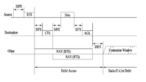
도 1은 무선랜 시스템에서 일반적으로 STA들이 데이터를 전송하는 방법을 설명하기 위한 도면이다.1 is a diagram for explaining a method of transmitting data by STAs in a wireless LAN system.
상술한 바와 같이 무선랜 시스템에서 제 1 STA(Source)이 제 2 STA (Destination)에 데이터를 전송하기 위해서는 매체가 유휴 상태인지, 혼잡 상태인지에 대한 센싱을 수행하여, 데이터 전송을 위한 TXOP(Transmission Opportunity)를 획득하는 경쟁 방식에 기반한다. As described above, in order to transmit data to the second STA (Source) in the wireless LAN system, the first STA (Source) performs sensing on whether the medium is in an idle state or a congested state and transmits a TXOP Opportunity.
도 1에서 제 1 STA은 제 2 STA에 데이터를 전송하기에 앞서 제 2 STA에 RTS (Request to Send) 프레임을 전송하고, 이에 응답하여 제 2 STA으로부터 CTS (Clear to Send) 프레임을 수신한다. 이와 같은 RTS/CTS 프레임의 교환은 잘 알려진 바와 같이 숨겨진 노드(Hidden Node)/노출된 노드(Exposed Node) 문제를 해결하기 위한 것으로서, 이를 통해 제 3 STA(other)는 RTS/CTS 수신에 따라 해당 데이터 전송 구간을 고려하여 NAV (Network Allocation Vector)를 설정할 수 있다. 제 3 STA은 NAV 설정 기간 동안 도 1에 도시된 바와 같이 매체에 접속하는 것을 지연시키며, NAV 기간이 종료된 후 경쟁 윈도우 내에서 백오프 절차를 수행하여 전송을 준비할 수 있다.In FIG. 1, the first STA transmits a request to send (RTS) frame to the second STA before transmitting data to the second STA, and receives a clear to send (CTS) frame from the second STA in response thereto. The exchange of the RTS / CTS frame is well known to solve the hidden node / exposed node problem. Accordingly, the third STA (other) A network allocation vector (NAV) can be set in consideration of a data transmission interval. The third STA delays connecting to the medium as shown in FIG. 1 during the NAV setup period, and can prepare for transmission by performing a backoff procedure within the contention window after the end of the NAV period.
한편, 제 2 STA으로부터 CTS를 수신한 제 1 STA은 SIFS (Short Interframe Space) 이후에 데이터를 전송하고, 제 1 STA으로부터 데이터를 수신한 제 2 STA은 이에 대해 ACK 프레임을 전송할 수 있다. Meanwhile, the first STA receiving the CTS from the second STA transmits data after SIFS (Short Interframe Space), and the second STA receiving the data from the first STA can transmit an ACK frame thereto.
이와 같은 일반적인 경쟁 기반 데이터 전송과 대비하여 IEEE 802.11ax 시스템 (이하 ‘High Efficiency 시스템’ 또는 ‘HE 시스템’이라 함)에서는 다중 사용자 전송 방식이 이용됨에 따라 복수의 STA의 데이터를 AP (Access Point)로 전송하는 상향링크 다중 전송 및 AP의 데이터를 복수의 STA에게 전송하는 하향링크 다중 전송이 이용되며, 이에 따라 각각 상향링크 스케줄링 및 하향링크 스케줄링에 기반한 통신이 요구되고 있다.In contrast to the conventional contention-based data transmission, a multi-user transmission scheme is used in an IEEE 802.11ax system (hereinafter referred to as a 'High Efficiency system' or 'HE system' Uplink multiplexing transmission and downlink multiplexing transmission of data of an access point (AP) to a plurality of STAs are used. Accordingly, communication based on uplink scheduling and downlink scheduling is required.
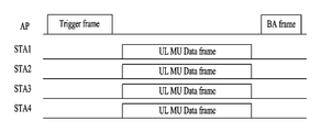
도 2는 HE 시스템에서 상향링크 다중 사용자 전송 상황을 설명하기 위한 도면이다.2 is a diagram for explaining an uplink multi-user transmission situation in the HE system.
상술한 바와 같이 HE 시스템에서는 상향링크 다중 사용자(UL MU) 전송 방식이 사용될 수 있으며, 이는 도 2에 도시된 바와 같이 AP가 복수의 STA (예를 들어, STA 1 내지 STA 4)에게 트리거 프레임(Trigger Frame)을 전송함으로써 시작될 수 있다. 트리거 프레임은 UL MU 할당 정보(예를 들어, 자원 위치 및 크기, STA ID들, MCS,MU 타입 (MIMO, OFDMA 등))를 포함할 수 있다. 구체적으로 트리거 프레임에 포함되어 전송될 수 있는 정보로는 이하에서 트리거 프레임의 구조와 함께 상세하게 설명한다.As described above, in the HE system, an UL MU transmission scheme can be used. This is because the AP transmits a trigger frame (STA1 to STA4) to a plurality of STAs (e.g., STA1 to STA4) Trigger Frame). The trigger frame may include UL MU allocation information (e.g., resource location and size, STA IDs, MCS, MU type (MIMO, OFDMA, etc.)). Specifically, the information that can be transmitted and included in the trigger frame will be described in detail below together with the structure of the trigger frame.
AP로부터 트리거 프레임을 수신한 복수의 STA (STA 1-4)는 각각 트리거 프레임의 스케줄링 정보에 기반하여 UL MU 데이터 프레임을 전송할 수 있으며, 이에 대해 AP는 각각 확인응답 신호(ACK)를 전송할 수 있으며, 효율을 위해 확인응답 신호는 BA (Block ACK) 또는 다중 사용자 BA (Multi User Block ACK) 프레임을 통해 전송할 수도 있다.A plurality of STAs (STAs 1-4) receiving a trigger frame from the AP can transmit an UL MU data frame based on the scheduling information of the trigger frame, respectively, and the AP can transmit an acknowledgment signal (ACK) For efficiency, the acknowledgment signal may be transmitted via a Block Ack (BA) or a Multi-User Block ACK (BA) frame.
상향링크 스케줄링 정보Uplink scheduling information
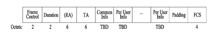
도 3 내지 5는 HE 시스템에서 이용되는 트리거 프레임의 포맷을 설명하기 위한 도면이다.3 to 5 are diagrams for explaining the format of a trigger frame used in the HE system.
구체적으로, 도 4는 도 3에 도시된 트리거 프레임에서 공통 정보 필드(Common Info)를 구체적으로 도시한 도면이며, 도 5는 도 3에 도시된 트리거 프레임에서 사용자 특정 정보 필드(Per User Info)를 구체적으로 도시한 도면이다.4 is a diagram specifically showing a common information field (Common Info) in the trigger frame shown in FIG. 3, and FIG. 5 is a view showing a user-specific information field (Per User Info) in the trigger frame shown in FIG. Fig.
도 3에서 구간(Duration) 필드는 해당 프레임의 길이를 알려주며, RA 필드는 트리거 프레임의 수신 STA, TA 필드는 트리거 프레임의 전송 STA을 나타낼 수 있다. In FIG. 3, the Duration field indicates the length of the corresponding frame. The RA field indicates a receiving STA of the trigger frame, and the TA field indicates a transmitting STA of the trigger frame.
도 4에 도시된 공통 정보 필드에서 길이 서브필드는 트리거 프레임에 응답하여 전송되는 HE 트리거 기반 PPDU의 L-SIG 길이 필드의 값을 나타낼 수 있다. 도 4에서 Cascade 지시자 서브필드가 1로 설정되는 경우 현재 수신된 트리거 프레임에 후속하여 다른 트리거 프레임이 전송되는 것을 나타낼 수 있다. 그렇지 않은 경우, Cascade 지시자 서브필드는 0으로 설정된다.In the common information field shown in FIG. 4, the length subfield may indicate the value of the L-SIG length field of the HE trigger-based PPDU transmitted in response to the trigger frame. In FIG. 4, when the Cascade indicator subfield is set to '1', it may indicate that another trigger frame is transmitted following the currently received trigger frame. Otherwise, the Cascade Indicator subfield is set to zero.
공통 정보 필드의 HE SIG-A 정보 서브필드는 트리거 프레임에 응답하여 전송되는 HE 트리거 기반 PPDU 응답의 HE-SIG A 필드의 컨텐츠를 나타낼 수 있다. The HE SIG-A information sub-field of the common information field may indicate the contents of the HE-SIG A field of the HE trigger-based PPDU response transmitted in response to the trigger frame.
도 4에서 CP 및 LTF 타입 서브필드는 HE 트리거 기반 PPDU 응답의 CP 및 HE-LTF 타입을 나타낼 수 있다. 이에 따라 나타낼 수 있는 CP 및 LTF 타입은 다음과 같다.4, the CP and LTF type subfields may represent the CP and HE-LTF types of the HE trigger-based PPDU response. The CP and LTF types that can be represented accordingly are as follows.
도 4에서 트리거 타입 서브필드는 트리거 프레임의 타입을 나타낼 수 있다. 트리거 프레임의 타입은 다음과 같은 값을 가질 수 있다.In FIG. 4, the trigger type subfield may indicate the type of the trigger frame. The type of the trigger frame can have the following values.
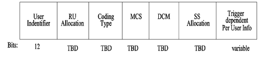
한편, 도 5에 도시한 사용자 특정 정보에 대해 설명하면 다음과 같다.The user-specific information shown in FIG. 5 will be described below.
먼저, 사용자 식별자 서브필드는 HE 트리거 기반 PPDU 내 MPDU(들)을 전송하기 위한 RU(Resource Unit)에 할당된 STA의 AID를 나타낸다. First, the user identifier subfield indicates the AID of the STA assigned to an RU (Resource Unit) for transmitting the MPDU (s) in the HE trigger-based PPDU.
그리고, 사용자 특정 정보 필드의 RU 할당 서브필드는 상술한 사용자 식별자 서브필드에 의해 지시되는 STA이 HE 트리거 기반 PPDU 전송 사용하는 RU를 나타낸다.The RU assignment sub-field of the user specific information field indicates an RU used by the STA indicated by the user identifier subfield described above to transmit the HE trigger-based PPDU.
사용자 특정 필드의 코딩 타입 서브필드는 HE 트리거 기반 PPDU의 코딩 타입을 나타낸다. 예를 들어, 해당 필드가 0으로 설정되는 경우 BCC를, 1로 설정되는 경우 LDPC를 나타낼 수 있다.The coding type subfield of the user specific field indicates the coding type of the HE trigger based PPDU. For example, BCC may be indicated if the field is set to 0, and LDPC if it is set to 1.
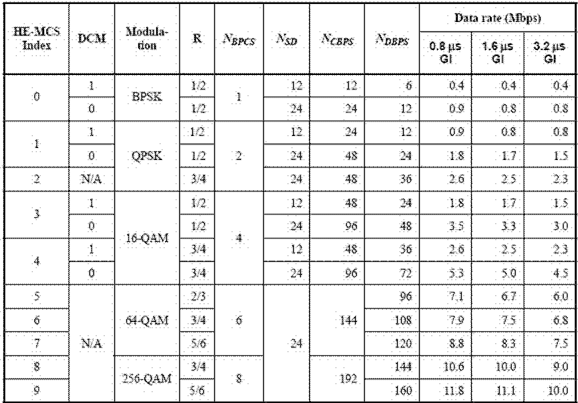
또한, MCS 서브필드는 HE 트리거 기반 PPDU 응답에 적용될 MCS를 나타낼 수 있다. 아래는 1개의 스트림, 26-톤 RU에 적용될 수 있는 MCS를 예를 든 것이다.In addition, the MCS subfield may indicate the MCS to be applied to the HE trigger-based PPDU response. Below is an example of an MCS that can be applied to one stream, 26-tone RU.
도 5에서 DCM 서브필드는 HE 트리거 기반 PPDU 응답에 DCM (Dual Carrier Modulation)이 적용되는지 여부를 나타낼 수 있다. 해당 서브필드 값이 1로 설정된 경우 HE 트리거 기반 PPDU에 DCM이 적용되는 것을 나타내며, 반대의 경우에는 해당 서브필드 값은 0으로 설정된다.In FIG. 5, the DCM subfield may indicate whether DCM (Dual Carrier Modulation) is applied to the HE trigger-based PPDU response. If the corresponding subfield value is set to 1, it indicates that the DC trigger is applied to the HE trigger-based PPDU, and in the opposite case, the corresponding subfield value is set to zero.
SS 할당 서브필드는 HE 트리거 기반 PPDU 응답의 공간 스트림의 수를 나타낼 수 있다.The SS Assignment subfield may represent the number of spatial streams of the HE trigger based PPDU response.
한편, 패딩 필드는 각 HE STA들이 UL MU 전송을 위해 준비할 수 있는 시간을 제공하기 위한 것이다.The padding field, on the other hand, is to provide a time for each HE STA to prepare for UL MU transmission.
상술한 바와 같이 상향링크 다중 사용자 전송 방식에 있어서는 트리거(Trigger) 프레임을 이용하여 상향링크 다중 사용자 전송을 위한 PPDU (Physical Protocol Data Unit) 전송에 대한 스케줄링 정보를 전송할 수 있다. 다만, AP가 하향링크 다중 사용자 전송을 위한 PPDU를 전송하고 이에 대한 확인응답 신호를 다중 사용자 방식으로 수신하기 위해 별도의 트리거 프레임을 전송하는 경우, 절차가 지연되고 불필요한 시그널링 오버헤드가 발생할 수 있다.As described above, in the uplink multi-user transmission scheme, it is possible to transmit scheduling information for PPDU (Physical Protocol Data Unit) transmission for uplink multi-user transmission using a Trigger frame. However, if the AP transmits a PPDU for downlink multi-user transmission and transmits a separate trigger frame to receive the acknowledgment signal in the multi-user mode, the procedure may be delayed and unnecessary signaling overhead may occur.
상향링크 확인응답 신호를 위한 스케줄링 정보 전송 방식Scheduling information transmission method for uplink acknowledgment signal
도 6은 본 발명의 일 실시예에 따라 상향링크 확인응답 신호를 전송하는 방법을 설명하기 위한 도면이다.6 is a diagram for explaining a method of transmitting an uplink acknowledgment signal according to an embodiment of the present invention.
하향링크 다중 사용자 전송 방식에 의한 하향링크 데이터에 대한 확인응답 신호 역시 다중 사용자 방식 등으로 전송될 수 있다. 이와 같은 확인응답 신호의 다중 사용자 방식 전송 등으로 전송되기 위해서는 이에 대한 스케줄링 정보가 요구될 수 있다.An acknowledgment signal for the downlink data by the downlink multi-user transmission scheme may also be transmitted through a multi-user scheme or the like. In order to transmit the acknowledgment signal through the multi-user scheme transmission, the scheduling information may be required.
상술한 바와 같이 일반적인 상향링크 다중 사용자 전송 방식에 있어서는 트리거(Trigger) 프레임을 이용하여 상향링크 다중 사용자 전송을 위한 PPDU (Physical Protocol Data Unit) 전송에 대한 스케줄링 정보를 전송할 수 있다. 다만, AP가 하향링크 다중 사용자 전송을 위한 PPDU를 전송하고 이에 대한 확인응답 신호를 다중 사용자 방식으로 수신하기 위해 별도의 트리거 프레임을 전송하는 경우, 절차가 지연되고 불필요한 시그널링 오버헤드가 발생할 수 있다.As described above, in a general uplink multi-user transmission scheme, it is possible to transmit scheduling information for PPDU (Physical Protocol Data Unit) transmission for uplink multi-user transmission using a Trigger frame. However, if the AP transmits a PPDU for downlink multi-user transmission and transmits a separate trigger frame to receive the acknowledgment signal in the multi-user mode, the procedure may be delayed and unnecessary signaling overhead may occur.
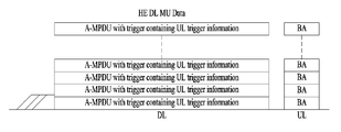
이를 위한 본 발명의 일 실시예에서는 도 6에 도시된 바와 같이 하향링크 다중 사용자 방식으로 데이터를 전송할 때 상향링크 트리거 정보를 DL PPDU에 포함하여 전송하는 방법을 이용할 수 있다. 도 6에서는 각 사용자에게 전송되는 A-MPDU에 UL 트리거 정보를 포함시켜 전송하는 것을 도시하고 있으며, 이에 따라 각 STA은 DL PPDU에 포함되어 수신된 UL 트리거 정보에 따라 BA를 전송하는 것을 도시하고 있다. 물론, 확인응답 신호를 전송하는 방식에는 일반 ACK, BA, 다중 사용자 BA 등 다양한 방법이 이용될 수 있다.For this purpose, in an embodiment of the present invention, as shown in FIG. 6, when data is transmitted in a downlink multi-user scheme, uplink trigger information may be included in a DL PPDU for transmission. FIG. 6 shows transmission of UL trigger information to an A-MPDU transmitted to each user, and each STA includes a DL PPDU and transmits BA according to the received UL trigger information . Of course, various methods such as general ACK, BA, and multi-user BA can be used as a method of transmitting an acknowledgment signal.
이와 같이 DL PPDU에 UL MU 스케줄링 정보를 포함하는 방식에는 다양한 방식이 있을 수 있으나, 이하의 실시예에서는 무선랜 시스템에서 이용되고 있는 A-Control 서브필드를 이용하는 방식을 설명한다.There are various schemes for including the UL MU scheduling information in the DL PPDU, but in the following embodiments, a method using the A-Control subfield used in the wireless LAN system will be described.
도 7 내지 8은 본 발명의 일 실시예에서 DL PPDU에 포함되어 상향링크 스케줄링 정보를 전송하는데 이용될 수 있는 A-Control 서브필드의 포맷을 도시한 도면이다.7 to 8 are diagrams illustrating the format of an A-Control subfield that can be used to transmit uplink scheduling information included in a DL PPDU in an embodiment of the present invention.
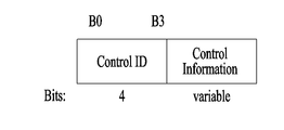
구체적으로 도 7은 복수(N개)의 A-Control 서브필드를 포함하는 구조를 도시하고 있으며, 각각의 제어 서브필드는 30 비트 길이를 가지는 것을 도시하고 있다. 또한 A-Control 서브필드를 구성하는 각각의 제어 서브필드는 도 8에 도시된 바와 같이 4비트의 제어 ID 필드를 포함할 수 있으며, 제어 ID 필드 값은 다음과 같이 설정될 수 있다.Specifically, FIG. 7 shows a structure including a plurality (N) of A-Control subfields, and each control subfield has a length of 30 bits. In addition, each control subfield constituting the A-Control subfield may include a 4-bit control ID field as shown in FIG. 8, and the control ID field value may be set as follows.
즉, 본 실시예에서 다루는 상향링크 다중 사용자 응답 스케줄링 정보를 전송하는 경우는 도 8의 제어 ID 필드 값이 0으로 설정되는 경우를 가정한다.That is, it is assumed that the control ID field value of FIG. 8 is set to 0 when the uplink multi-user response scheduling information is handled in the present embodiment.
이와 같은 고찰 하에 살펴보면, DL PPDU를 통해 UL MU 스케줄링 정보를 전송하기 위해 A-Control 서브필드를 이용하는 경우, 도 7에 도시된 30 비트의 공간 하에 제어 ID를 위한 4 비트를 제외하고 전체 26 비트의 정보를 통해 필요한 UL MU 스케줄링 정보를 전송하는 것이 요구된다. 이를 상술한 트리거 프레임을 통해 전송되는 UL 스케줄링 정보의 크기와 비교하면 상당히 제한된 공간임을 알 수 있으며, 이를 위해 본 발명의 바람직한 실시예에서는 위와 같은 A-Control 서브필드 내 제어 필드 26 비트 내에 포함되어야 할 제어 정보에 대해 살펴보고, 만일 포함되지 않은 경우 STA은 해당 정보를 어떻게 설정할 수 있을지에 대해 살펴본다.In the case of using the A-Control subfield for transmitting the UL MU scheduling information through the DL PPDU, it is assumed that a total of 26 bits except the 4 bits for the control ID are allocated in the space of 30 bits shown in FIG. It is required to transmit necessary UL MU scheduling information through information. It can be seen that it is a fairly limited space compared with the size of the UL scheduling information transmitted through the trigger frame described above. For this, in the preferred embodiment of the present invention, the control field in the A- Look at the control information, and if it is not included, the STA will look at how the information can be set.
DL PPDU의 제어 필드에 포함될 스케줄링 정보에 대한 검토Review of scheduling information to be included in control field of DL PPDU
도 9는 본 발명의 일 실시예에 따른 DL PPDU에 포함될 UL MU 스케줄링 정보 중 가장 기본이 되는 제어 정보를 설명하기 위한 도면이다.9 is a diagram for explaining the most basic control information among UL MU scheduling information to be included in a DL PPDU according to an embodiment of the present invention.
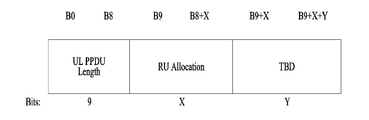
트리거 프레임을 통해 전송되는 다양한 상향링크 스케줄링 정보 중 도 8에 도시된 26 비트에 첫번째로 포함되어야 기본적인 제어 정보로는 도 9에 도시된 바와 같이 UL PPDU 길이 정보 및 RU 할당 정보가 있다. DL 데이터에 대한 BA 전송을 위해 UL MU 스케줄링 정보를 전송하는 이유는 해당 UL PPDU의 길이와 RU 할당 정보를 알려주기 위함이기 때문이다.Among the various uplink scheduling information transmitted through the trigger frame, the first control information included in the 26 bits shown in FIG. 8 includes UL PPDU length information and RU allocation information as shown in FIG. The reason for transmitting the UL MU scheduling information for the BA transmission to the DL data is to inform the length of the UL PPDU and the RU allocation information.
도 9에 도시된 바와 같이 9비트의 UL PPDU 길이 서브필드를 가지는 경우, 1 us의 granularity로는 512 us까지의 길이를 나타낼 수 있고, 2us의 granularity로는 1024us까지의 길이를 나타낼 수 있다. As shown in FIG. 9, when a 9-bit UL PPDU length subfield is used, a 1 us granularity may represent a length of 512 us, and a 2us granularity may represent a length of 1024 us.
다만, 데이터 필드의 OFDMA 심볼을 나타내는 경우, 6비트의 UL PPDU 길이는 64*(12.8us+0.8us) + legacy PHY header length + length of HE SIG-A + HE LTF length > 870us까지 나타낼 수 있고, 5비트의 UL PPDU 길이는 32*(12.8us+0.8us) + legacy PHY header length + length of HE SIG-A + HE LTF length>435.2us까지 나타낼 수 있다. 따라서, 추가적인 제어 정보를 위한 공간을 고려할 경우, 본 발명의 바람직한 실시예에서는 도 9에 도시된 바와 같이 UL PPDU 길이 서브필드에 9비트까지 할당 한 것과 달리 5/6 비트의 길이도 충분한 것으로 판단되어 이와 같이 짧은 길이의 UL PPDU 길이 서브필드를 이용하는 것을 제안한다.However, in the case of representing the OFDMA symbol of the data field, the UL PPDU length of 6 bits can be represented by 64 * (12.8us + 0.8us) + legacy PHY header length + length of HE SIG-A + HE LTF length> 870us, The 5-bit UL PPDU length can be expressed as 32 * (12.8us + 0.8us) + legacy PHY header length + length of HE SIG-A + HE LTF length> 435.2us. Therefore, in a preferred embodiment of the present invention, it is determined that a length of 5/6 bits is sufficient as compared to 9 bits allocated in the UL PPDU length subfield, as shown in FIG. 9 It is proposed to use the UL PPDU length subfield of such a short length.
한편, RU 할당 서브필드는 UL MU 응답을 전송하기 위해 할당되는 RU를 나타낸다. On the other hand, the RU assignment subfield indicates an RU assigned to transmit the UL MU response.
RU 할당 서브필드에 대한 가장 간단한 설정은 트리거 프레임에 할당되는 것과 동일하게 8비트 길이로 설정하는 것이다. 다만, 추가적으로 포함되어야 할 다른 제어 정보를 고려하여 해당 필드를 7비트로 설정하고, 다음과 같이 운용할 수도 있다.The simplest setting for the RU assignment subfield is to set it to 8 bits long, the same as that assigned to the trigger frame. However, considering the other control information to be additionally included, the corresponding field may be set to 7 bits, and the following operation may be performed.
예를 들어 하나의 80 MHz 채널을 통한 DL MU 전송은 다른 80 MHz 채널을 통한 ACK/BA/M-BA를 통해 확인되지 않도록 설정할 수 있다. 만일 위와 같은 경우 확인되지 않은 80 MHz 대역에 사용자가 많은 경우 해당 옵션은 적절한 옵션이 아닐 수 있으나, 이러한 경우는 빈번한 경우가 아니기 때문에 트리거 프레임을 이용하도록 설정할 수도 있다.For example, DL MU transmissions over one 80 MHz channel can be configured not to be acknowledged over ACK / BA / M-BA over another 80 MHz channel. If there are many users in the unconfirmed 80 MHz band, the option may not be an appropriate option, but in this case it can be set to use a trigger frame because it is not a frequent case.
도 9와 관련하여 상술한 UL PPDU 길이 및 RU 할당을 제외한 나머지 스케줄링 정보에 대해 살펴보면 다음과 같다.The remaining scheduling information excluding the UL PPDU length and the RU allocation described above with reference to FIG. 9 will be described below.
도 10은 본 발명의 바람직한 일 실시예에 따라 DL PPDU의 제어 서브필드를 통해 전송될 UL MU 스케줄링 정보의 일례를 도시한 도면이다.10 is a diagram illustrating an example of UL MU scheduling information to be transmitted through a control subfield of a DL PPDU according to a preferred embodiment of the present invention.
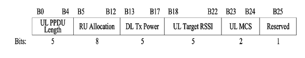
도 10에 도시된 바와 같이 본 실시예에 따른 제어 정보 서브필드는 상향링크 PPDU의 길이 정보, 상향링크 PPDU에 대한 RU(Resource Unit) 할당 정보, 상향링크 PPDU에 대한 상향링크 MCS 정보, AP의 전송 전력(DL Tx Power), 및 AP의 타겟 RSSI(Target receive signal strength indicator) 정보를 포함하도록 설정하는 것을 제안한다.As shown in FIG. 10, the control information subfield according to this embodiment includes the length information of the uplink PPDU, the RU (Resource Unit) allocation information for the uplink PPDU, the uplink MCS information for the uplink PPDU, Power (DL Tx Power), and target RSSI (target receive signal strength indicator) information of the AP.
트리거 프레임을 통해 전송되는 UL MU 스케줄링 정보 중 명시적인 시그널링이 필요한 정보로서, 상향링크 PPDU의 길이 정보, 상향링크 PPDU에 대한 RU 할당 정보, 상향링크 PPDU에 대한 상향링크 MCS 정보, AP의 전송 전력, 및 AP의 타겟 RSSI정보를 선택하는 것을 의미한다. 다른 제어 정보의 경우에는 후술하는 바와 같이 AP의 명시적인 시그널링이 없이 STA측에서 DL PPDU의 수신 정보를 통해 추정하거나, 미리 설정된 값을 이용하는 것을 제안한다.Information required for explicit signaling among UL MU scheduling information transmitted through a trigger frame includes information on the length of the uplink PPDU, RU allocation information on the uplink PPDU, uplink MCS information on the uplink PPDU, transmission power of the AP, And selecting the target RSSI information of the AP. In the case of the other control information, it is proposed that the STA side estimates the reception information of the DL PPDU using the pre-set value without explicit signaling of the AP as described later.
먼저, 상술한 상향링크 PPDU의 길이 정보 및 상향링크 PPDU에 대한 RU 할당 정보는 상술한 도 9와 관련하여 상술한 바와 같으나, 도 9의 9 비트의 UL PPDU 길이 서브필드를 포함하는 대신 상술한 바와 같은 이유로 5비트의 UL PPDU 길이 서브필드를 포함하는 것을 제안한다.The length information of the uplink PPDU and the RU allocation information of the uplink PPDU are as described above with reference to FIG. 9. However, instead of including the 9-bit UL PPDU length subfield of FIG. 9, For the same reason, it is proposed to include a 5-bit UL PPDU length subfield.
도 9와 대비하여 추가적으로 포함되는 DL Tx Power 및 UL Target RSSI 정보는 AP의 전송 전력과 AP에서 해당 UL MU PPDU 의 타겟 수신 전력이기 때문에 STA 측면에서 AP의 시그널링 없이 추정하기 어렵다. 따라서, 도 10에서는 각각의 5비트 길이를 가지는 총 10 비트를 송수신 전력 관련 정보의 시그널링을 위해 사용하는 것을 도시하고 있다.The DL Tx Power and the UL Target RSSI information, which are additionally included in comparison with FIG. 9, are difficult to estimate without signaling the AP on the STA side because the transmission power of the AP and the target receiving power of the corresponding UL MU PPDU in the AP. Therefore, in FIG. 10, a total of 10 bits each having a 5-bit length is used for signaling transmission / reception power related information.
한편, 도 10은 UL MCS 역시 명시적인 시그널링이 필요한 정보로서 포함하고 있다. 다만, 상술한 트리거 프레임에서 4비트의 MCS 정보를 알려주는 것과 달리 본 실시예에서는 2비트의 짧은 길이의 MCS를 이용하는 것을 제안한다. 이와 같은 2비트의 MCS는 전체 사용 가능한 MCS들 중 가장 낮은 변조 및 코딩 방식을 적용하는 4개의 MCS 중 어느 하나를 나타낼 수 있도록 설정하는 것이 바람직하다.On the other hand, FIG. 10 also includes UL MCS as information requiring explicit signaling. However, in the present embodiment, it is proposed to use 2-bit short-length MCS, instead of informing 4-bit MCS information in the above trigger frame. It is preferable that the 2-bit MCS is set to indicate any one of the four MCSs applying the lowest modulation and coding scheme among all available MCSs.
후술하는 바와 같이 UL MU 스케줄링 정보 중 생략되는 정보는 STA측에서 미리 결정된 값으로 설정하거나, 수신된 DL MU PPDU의 수신 정보를 이용하여 추정할 수 있다. 다만, ACK/BA/M-BA 전송의 경우 DL MU PPDU와 같은 데이터 전송에 이용된 MCS와 달리 더 Robust한 전송을 요구하는 것이 일반적이기 때문에 DL MU PPDU에 적용된 MCS를 그대로 차용하기 어렵다. 아울러, 채널 상황을 무시하고 고정된 MCS를 적용하는 것 역시 성능 열화를 가져올 수 있다.As will be described later, the information omitted in the UL MU scheduling information can be set to a predetermined value on the STA side or can be estimated using the reception information of the received DL MU PPDU. However, in the case of ACK / BA / M-BA transmission, unlike the MCS used for data transmission such as DL MU PPDU, it is difficult to borrow the MCS applied to the DL MU PPDU because it is more common to request a more robust transmission. In addition, ignoring the channel condition and applying fixed MCS can also lead to performance degradation.
도 10에 도시된 바와 같이 제어 필드에 상향링크 PPDU의 길이 정보, 상향링크 PPDU에 대한 RU(Resource Unit) 할당 정보, 상향링크 PPDU에 대한 상향링크 MCS 정보, AP의 전송 전력(DL Tx Power), 및 AP의 타겟 RSSI(Target receive signal strength indicator) 정보를 포함하도록 설정함으로써 26 비트 길이의 제어 정보를 구성할 수 있으며, 이는 도 8에 도시된 바와 같이 4비트의 제어 ID 필드와 함께 전체 30 비트의 서브필드 길이를 맞출 수 있다.As shown in FIG. 10, in the control field, the length information of the uplink PPDU, the RU (Resource Unit) allocation information for the uplink PPDU, the uplink MCS information for the uplink PPDU, the transmission power (DL Tx Power) And a target RSSI (target receive signal strength indicator) information of the AP to form control information of 26 bits in length. This is because the control ID field of 4 bits and the control ID field of all 30 bits The subfield length can be adjusted.
DL PPDU의 제어 필드에서 생략되는 스케줄링 정보의 처리에 대한 검토Review of processing of scheduling information omitted in control field of DL PPDU
1. DL MU PPDU의 수신 정보를 차용하는 제어 정보1. Control information for borrowing the reception information of the DL MU PPDU
도 10에 도시된 바와 같이 DL PPDU의 제어 정보 서브필드는 CP 및 LTF 구조 필드를 포함하지 않을 수 있다. 트리거 프레임에서는 이 필드를 나타내기 위해 2비트를 사용하고 있으나, 실제적으로는 UL MU PPDU를 위해서 사용되는 값은 2xLTF + 1.6us CP size와 4xLTF + 3.2us CP size 두 가지만 필요하다. 따라서, 본 발명의 다른 일 실시예에서는 1 bit LTF 및 CP 필드를 이용할 수도 있으며, 그러할 경우 해당 필드 값은 다음과 같이 나타내어질 수 있다.As shown in FIG. 10, the control information subfield of the DL PPDU may not include the CP and LTF structure fields. Trigger frames use 2 bits to represent this field, but in practice, only two values are needed for the UL MU PPDU: 2xLTF + 1.6us CP size and 4xLTF + 3.2us CP size. Accordingly, in another exemplary embodiment of the present invention, the 1-bit LTF and CP fields may be used. In this case, the corresponding field values may be expressed as follows.
(1) 0: 2xLTF and 1.6us CP size(1) 0: 2xLTF and 1.6us CP size
(2) 1: 4xLTF and 3.2us CP size(2) 1: 4xLTF and 3.2us CP size
다만, STA은 이와 같은 명시적인 시그널링이 없더라도 상기 하향링크 PPDU 수신에 따라 상향링크 PPDU의 CP 및 LTF 구조를 위와 같이 2가지 경우 중 어느 하나를 이용하도록 설정할 수 있다.However, even if there is no explicit signaling, the STA can set the CP and LTF structure of the uplink PPDU to use one of the above two cases according to the reception of the downlink PPDU.
또한, 도 10에 도시된 바와 같이 제어 정보 서브필드는 DCM (Dual Carrier Modulation) 정보를 포함하지 않을 수 있다. MCS의 경우 도 10과 관련하여 상술한 바와 같이 2비트의 간단한 시그널링을 통해 알려줄 수 있으며, 이에 추가적으로 DCM의 적용 여부는 STA에서 상기 DL MU PPDU의 MCS를 고려하여 상기 UL MU PPDU의 DCM 여부를 결정할 수 있다. 즉, 수신 DL MU PPDU에 DCM이 적용된 경우 UL MU PPDU에도 DCM을 적용하고, 반대의 경우에는 그에 따라 처리하도록 설정할 수 있다.In addition, as shown in FIG. 10, the control information subfield may not include DCM (Dual Carrier Modulation) information. MCS can be informed through simple 2-bit signaling as described above with reference to FIG. 10. In addition, whether the DCM is applied or not is determined by the STA in consideration of the MCS of the DL MU PPDU and whether the UL MU PPDU is DCM . That is, when DCM is applied to the receiving DL MU PPDU, DCM may be applied to the UL MU PPDU, and in the opposite case, processing may be performed accordingly.
이와 유사하게 제어 정보 서브필드는 대역폭 정보를 포함하지 않으며, STA은 UL MU PPDU의 대역폭을 DL MU PPDU의 대역폭과 동일하게 결정할 수 있다.Similarly, the control information subfield does not include bandwidth information, and the STA can determine the bandwidth of the UL MU PPDU to be equal to the bandwidth of the DL MU PPDU.
이상과 같은 제어 정보들은 STA이 AP로부터 명시적인 시그널링을 수신하지 않더라도 DL MU PPDU의 수신 정보를 통해 UL MU PPDU의 정보를 설정할 수 있다.The control information as described above can set the information of the UL MU PPDU through the reception information of the DL MU PPDU even if the STA does not receive the explicit signaling from the AP.
2. 해당 기능을 사용하지 않는 제어 정보2. Control information that does not use the feature
도 10에 도시된 바와 같이 DL PPDU의 제어 정보 서브필드는 공간 재사용(spatial reuse) 정보를 포함하지 않을 수 있다. 만일 기존 HE-SIG A에서 정의된 공간 재사용 필드가 사용된다면 이는 4비트의 길이를 차지할 것이다. 다만, UL MU 데이터 전송에 대한 ACK/BA/M-BA 전송에 있어서 공간 재사용의 적용에 따른 이득은 위와 같은 시그널링을 위한 공간 제한의 문제에 비해 크지 않다. 따라서, 본 발명의 일 실시예에서는 위와 같이 제어 정보 서브필드에 공간 재사용(spatial reuse) 정보를 포함하지 않도록 설정하고, STA은 DL PPDU 수신에 따라 공간 재사용이 비활성화(disable)되는 것으로 설정하는 것이 바람직하다.As shown in FIG. 10, the control information subfield of the DL PPDU may not include spatial reuse information. If the space reuse field defined in the existing HE-SIG A is used, it will take up to 4 bits. However, in ACK / BA / M-BA transmission for UL MU data transmission, the gain due to the application of space reuse is not large compared with the space limitation problem for the above signaling. Therefore, in one embodiment of the present invention, it is preferable to set not to include spatial reuse information in the control information subfield as described above, and to set the STA to disable the space reuse according to the reception of the DL PPDU Do.
유사한 취지에서, 상기 제어 정보 서브필드는 MU MIMO LTF 모드, STBC, 스트림 수, 스트림 할당, 및 코딩 타입 정보를 포함하지 않으며, STA은 상기 하향링크 PPDU 수신에 따라 상기 MU MIMO LTF 모드, 상기 STBC, 상기 스트림 수, 상기 스트림 할당 및 상기 코딩 타입에 대한 파라미터들을 0으로 설정할 수 있다.In a similar aspect, the control information subfield does not include MU MIMO LTF mode, STBC, stream number, stream allocation, and coding type information, and the STA may transmit the MU MIMO LTF mode, the STBC, The parameters for the number of streams, the stream allocation, and the coding type may be set to zero.
또한, Cascade indication 역시 별도의 시그널링 없이 0으로 설정되는 것이 바람직하다. Also, it is preferable that the cascade indication is set to 0 without any signaling.
차선의 실시예Lane embodiment
도 10에 도시된 실시예는 본 발명의 유일한 실시예는 아니며, 이하에서는 DL PPDU의 제어 필드의 다른 구성예들에 대해서도 살펴본다.The embodiment shown in FIG. 10 is not the only embodiment of the present invention, and other configurations of the control field of the DL PPDU will be described below.
(1) TXOP field (1) TXOP field
TXOP field는 기존에 MAC duration에서 15 bits가 사용되고, HE-SIG A에서는 5~7 bits사이 값 중 하나로 결정될 예정인데, 제한된 크기에서 TXOP을 넣기는 힘들기 때문에, 1 bit TXOP field를 이용할 수 있다. In the TXOP field, 15 bits are used for the MAC duration, and HE-SIG A is determined to be one of 5 to 7 bits. Since it is difficult to insert a TXOP in a limited size, a 1-bit TXOP field can be used.
해당 필드가 0로 설정되면, TXOP 값을 0으로 설정하라는 것을 가리킨다. 보통 해당 UL MU ACK/BA가 TXOP(TXOP의 UL)에서 마지막 프레임이면, 0으로 설정하도록 한다. If the field is set to 0, it indicates that the TXOP value should be set to zero. Normally, it should be set to 0 if the corresponding UL MU ACK / BA is the last frame in TXOP (UL of TXOP).
해당 필드가 1로 설정되면, TXOP을 계산을 통해서 나온 값으로 설정하라는 것을 지시한다. 보통 현재/이전 프레임의 MAC duration을 기반으로 설정한다.If the field is set to 1, it indicates that TXOP should be set to the value from the calculation. It is usually set based on the MAC duration of the current / previous frame.
(2-1) Delta MCS (2bits): (2-1) Delta MCS (2 bits):
0: 현재 수신된 DL 프레임의 MCS와 같은 MCS를 사용 0: Use the same MCS as the MCS of the currently received DL frame.
1: 현재 수신된 DL 프레임에서 사용된 MCS에서 X 단계 낮은 MCS를 사용 (X는 자연수, e.g., 1, 2,or 3)1: Use low-level MCS in the MCS used in the currently received DL frame (X is a natural number, e.g., 1, 2, or 3)
2: 현재 수신된 DL 프레임에서 사용된 MCS에서 Y 단계 낮은 MCS를 사용 (Y는 자연수, e.g., 2, 3 or 4)2: Y level low MCS is used in the MCS used in the currently received DL frame (Y is a natural number, e.g., 2, 3 or 4)
3: 가장 낮은 MCS(e.g., either MCS0 or MCS0 + DCM(1))를 사용3: Use the lowest MCS (eg, either MCS0 or MCS0 + DCM (1))
(2-2) Delta MCS (2bits): (2-2) Delta MCS (2 bits):
0: 현재 수신된 DL 프레임의 MCS와 같은 MCS를 사용 0: Use the same MCS as the MCS of the currently received DL frame.
1: 현재 수신된 DL 프레임에서 사용된 MCS에서 2 단계 낮은 MCS를 사용1: MCS used in the currently received DL frame is used with 2-level lower MCS
2: 가장 낮은 MCS(e.g., either MCS0 or MCS0 + DCM(1))를 사용2: Use the lowest MCS (eg, either MCS0 or MCS0 + DCM (1))
3: reserved3: reserved
(2-3) MCS (1bit): (2-3) MCS (1 bit):
0: 현재 수신된 DL 프레임의 MCS와 같은 MCS를 사용 0: Use the same MCS as the MCS of the currently received DL frame.
1: 가장 낮은 MCS(e.g., either MCS0 or MCS0 + DCM(1)) 를 사용1: Use the lowest MCS (eg, either MCS0 or MCS0 + DCM (1))
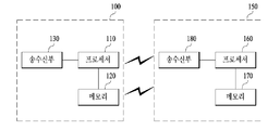
도 11은 본 발명의 일 실시예에 따른 AP 장치 (또는 기지국 장치) 및 스테이션 장치 (또는 단말 장치)의 예시적인 구성을 나타내는 블록도이다. 11 is a block diagram illustrating an exemplary configuration of an AP apparatus (or base station apparatus) and a station apparatus (or terminal apparatus) according to an embodiment of the present invention.
AP(100)는 프로세서(110), 메모리(120), 송수신기(130)를 포함할 수 있다. 스테이션(150)는 프로세서(160), 메모리(170), 송수신기(180)를 포함할 수 있다. The
송수신기(130 및 180)는 무선 신호를 송신/수신할 수 있고, 예를 들어, IEEE 802 시스템에 따른 물리 계층을 구현할 수 있다. 프로세서(110 및 160)는 송수신기(130 및 180)와 연결되어 IEEE 802 시스템에 따른 물리 계층 및/또는 MAC 계층을 구현할 수 있다. 프로세서(110 및 160)는 전술한 본 발명의 다양한 실시예들의 하나 또는 둘 이상의 조합에 따른 동작을 수행하도록 구성될 수 있다. 또한, 전술한 본 발명의 다양한 실시예에 따른 AP 및 스테이션의 동작을 구현하는 모듈이 메모리(120 및 170)에 저장되고, 프로세서(110 및 160)에 의하여 실행될 수 있다. 메모리(120 및 170)는 프로세서(110 및 160)의 내부에 포함되거나 또는 프로세서(110 및 160)의 외부에 설치되어 프로세서(110 및 160)와 공지의 수단에 의해 연결될 수 있다. The
전술한 AP 장치(100) 및 스테이션 장치(150)에 대한 설명은 다른 무선 통신 시스템(예를 들어, LTE/LTE-A 시스템)에서의 기지국 장치 및 단말 장치에 대해서 각각 적용될 수 있다. The description of the above-described
위와 같은 AP 및 스테이션 장치의 구체적인 구성은, 전술한 본 발명의 다양한 실시예에서 설명한 사항들이 독립적으로 적용되거나 또는 2 이상의 실시예가 동시에 적용되도록 구현될 수 있으며, 중복되는 내용은 명확성을 위하여 설명을 생략한다. The specific configurations of the AP and the station apparatus may be implemented such that the elements described in the various embodiments of the present invention described above are applied independently or two or more embodiments are applied at the same time. do.
상술한 바와 같이 개시된 본 발명의 바람직한 실시형태에 대한 상세한 설명은 당업자가 본 발명을 구현하고 실시할 수 있도록 제공되었다. 상기에서는 본 발명의 바람직한 실시 형태를 참조하여 설명하였지만, 해당 기술 분야의 숙련된 당업자는 하기의 특허 청구의 범위에 기재된 본 발명의 사상 및 영역으로부터 벗어나지 않는 범위 내에서 본 발명을 다양하게 수정 및 변경시킬 수 있음을 이해할 수 있을 것이다. 따라서, 본 발명은 여기에 나타난 실시형태들에 제한되려는 것이 아니라, 여기서 개시된 원리들 및 신규한 특징들과 일치하는 최광의 범위를 부여하려는 것이다. 또한, 이상에서는 본 명세서의 바람직한 실시예에 대하여 도시하고 설명하였지만, 본 명세서는 상술한 특정의 실시예에 한정되지 아니하며, 청구범위에서 청구하는 본 명세서의 요지를 벗어남이 없이 당해 발명이 속하는 기술분야에서 통상의 지식을 가진 자에 의해 다양한 변형실시가 가능한 것은 물론이고, 이러한 변형 실시들은 본 명세서의 기술적 사상이나 전망으로부터 개별적으로 이해되어서는 안될 것이다.DETAILED DESCRIPTION OF THE PREFERRED EMBODIMENTS The foregoing description of the preferred embodiments of the present invention has been presented for those skilled in the art to make and use the invention. It will be apparent to those skilled in the art that various modifications and variations can be made in the present invention without departing from the spirit or scope of the present invention as defined by the following claims It can be understood that Accordingly, the present invention is not intended to be limited to the embodiments shown herein but is to be accorded the widest scope consistent with the principles and novel features disclosed herein. While the present invention has been particularly shown and described with reference to exemplary embodiments thereof, it is to be understood that the invention is not limited to the disclosed exemplary embodiments, but, on the contrary, It will be understood by those skilled in the art that various changes and modifications may be made without departing from the spirit and scope of the present invention.
그리고 당해 명세서에서는 물건 발명과 방법 발명이 모두 설명되고 있으며, 필요에 따라 양 발명의 설명은 보충적으로 적용될 수 있다.In this specification, both the invention and the method invention are explained, and the description of both inventions can be supplemented as necessary.
상술된 바와 같이 본 발명의 실시예들은 IEEE 802.11 시스템을 비롯한 다양한 무선 통신 시스템에 적용될 수 있다.As described above, embodiments of the present invention can be applied to various wireless communication systems including an IEEE 802.11 system.
Claims (15)
상향링크 스케줄링 정보를 포함하는 제어 정보 서브필드, 및 하향링크 데이터를 포함하는 하향링크 PPDU(Physical Protocol Data Unit)를 AP(Access Point)로부터 수신하고,
상기 상향링크 스케줄링 정보에 따라 상기 하향링크 데이터에 대한 확인응답 신호를 포함하는 상향링크 PPDU를 상기 AP에 전송하되,
상기 제어 정보 서브필드는,
상기 상향링크 PPDU의 길이 정보,
상기 상향링크 PPDU에 대한 RU(Resource Unit) 할당 정보,
상기 상향링크 PPDU에 대한 상향링크 MCS 정보,
상기 AP의 전송 전력, 및
상기 AP의 타겟 RSSI(Target receive signal strength indicator) 정보
를 포함하는, 확인응답 신호 전송 방법.A method for transmitting an acknowledgment signal for downlink data in a wireless local area network (STA)
A control information subfield including uplink scheduling information, and a physical protocol data unit (PPDU) including downlink data from an access point (AP)
Transmitting an uplink PPDU including an acknowledgment signal for the downlink data to the AP according to the uplink scheduling information,
Wherein the control information subfield comprises:
Length information of the uplink PPDU,
RU (Resource Unit) allocation information for the uplink PPDU,
Uplink MCS information for the uplink PPDU,
The transmit power of the AP, and
The target receive signal strength indicator (RSSI) information of the AP
And transmitting the acknowledgment signal.
상기 제어 정보 서브필드는 공간 재사용 정보를 포함하지 않으며,
상기 STA은 상기 하향링크 PPDU 수신에 따라 공간 재사용이 비활성화되는 것으로 설정하는, 확인응답 신호 전송 방법.The method according to claim 1,
The control information subfield does not include space reuse information,
Wherein the STA sets the space reuse to be inactive according to the reception of the downlink PPDU.
상기 STA은 상기 하향링크 PPDU 수신에 따라 상기 상향링크 PPDU의 CP (Cyclic Prefix) 및 LTF 구조를,
(1) 4x LTF 와 3.2 us CP를 이용하는 구조, 또는
(2) 2x LTF와 1.6 us CP를 이용하는 구조
2가지 중 하나로만 선택하는, 확인응답 신호 전송 방법.The method according to claim 1,
The STA receives a Cyclic Prefix (CP) and an LTF structure of the uplink PPDU according to the downlink PPDU reception,
(1) a structure using 4x LTF and 3.2 us CP, or
(2) Structure using 2x LTF and 1.6 us CP
A method for transmitting an acknowledgment signal, the method comprising selecting only one of the two.
상기 제어 정보 서브필드는 DCM (Dual Carrier Modulation) 정보를 포함하지 않으며,
상기 STA은 상기 하향링크 PPDU의 MCS를 고려하여 상기 상향링크 PPDU의 DCM 여부를 결정하는, 확인응답 신호 전송 방법.The method according to claim 1,
The control information subfield does not include DCM (Dual Carrier Modulation) information,
Wherein the STA determines whether the uplink PPDU is DCM in consideration of the MCS of the downlink PPDU.
상기 제어 정보 서브필드는 대역폭 정보를 포함하지 않으며,
상기 STA은 상기 상향링크 PPDU의 대역폭을 상기 하향링크 PPDU의 대역폭과 동일하게 결정하는, 확인응답 신호 전송 방법.The method according to claim 1,
The control information subfield does not include bandwidth information,
Wherein the STA determines the bandwidth of the uplink PPDU to be equal to the bandwidth of the downlink PPDU.
상기 제어 정보 서브필드는 MU MIMO LTF 모드, STBC, 스트림 할당, 스트림 수 및 코딩 타입 정보를 포함하지 않으며,
상기 STA은 상기 하향링크 PPDU 수신에 따라 상기 MU MIMO LTF 모드, 상기 STBC, 상기 스트림 할당, 상기 스트림 수 및 상기 코딩 타입에 대한 파라미터들을 0으로 설정하는, 확인응답 신호 전송 방법.The method according to claim 1,
The control information subfield does not include MU MIMO LTF mode, STBC, stream allocation, stream number, and coding type information,
Wherein the STA sets the parameters for the MU MIMO LTF mode, the STBC, the stream allocation, the number of streams, and the coding type to zero according to the downlink PPDU reception.
상기 MCS 정보는 2비트 길이를 가지며,
상기 STA은 미리 정해진 복수의 MCS 레벨들 중 가장 낮은 4개의 MCS 레벨 중 상기 MCS 정보에 대응하는 MCS 레벨을 선택하는, 확인응답 신호 전송 방법.The method according to claim 1,
The MCS information has a length of 2 bits,
Wherein the STA selects an MCS level corresponding to the MCS information among four lowest MCS levels among a plurality of predetermined MCS levels.
상기 상향링크 PPDU는 상기 하향링크 데이터에 대한 개별 확인응답 신호, BA (Block Ack) 또는 다중 사용자 BA (Multi-STA Block Ack) 중 하나를 포함하는, 확인응답 신호 전송 방법.The method according to claim 1,
Wherein the uplink PPDU includes one of an individual acknowledgment signal for the downlink data, a BA (Block Ack) or a multi-user BA (Multi-STA Block Ack).
상기 제어 정보 서브필드는 4비트 길이의 제어 ID 정보를 추가적으로 포함하여 30 비트 길이를 가지며,
상기 상향링크 PPDU의 길이 정보는 5비트 길이를 가지는, 확인응답 신호 전송 방법.The method according to claim 1,
The control information subfield further includes control ID information of 4 bits in length and has a length of 30 bits,
Wherein the length information of the uplink PPDU has a length of 5 bits.
상향링크 스케줄링 정보를 포함하는 제어 정보 서브필드, 및 하향링크 데이터를 포함하는 하향링크 PPDU(Physical Protocol Data Unit)를 AP(Access Point)로부터 수신하도록 구성되는 송수신기; 및
상기 상향링크 스케줄링 정보를 처리하여, 상기 하향링크 데이터에 대한 확인응답 신호를 포함하는 상향링크 PPDU를 상기 송수신기를 통해 상기 AP에 전송하도록 제어하는 프로세서를 포함하되,
상기 프로세서는 상기 제어 정보 서브필드가,
상기 상향링크 PPDU의 길이 정보,
상기 상향링크 PPDU에 대한 RU(Resource Unit) 할당 정보,
상기 상향링크 PPDU에 대한 상향링크 MCS 정보,
상기 AP의 전송 전력, 및
상기 AP의 타겟 RSSI(Target receive signal strength indicator) 정보
를 포함하는 것을 가정하여 상기 상향링크 스케줄링 정보를 처리하는, 스테이션.A station (STA) for transmitting an acknowledgment signal for downlink data in a wireless LAN system,
A transceiver configured to receive a control information subfield including uplink scheduling information and a physical protocol data unit (PPDU) including downlink data from an AP; And
And a processor for processing the uplink scheduling information and controlling transmission of an uplink PPDU including an acknowledgment signal for the downlink data to the AP through the transceiver,
Wherein the processor is further configured to:
Length information of the uplink PPDU,
RU (Resource Unit) allocation information for the uplink PPDU,
Uplink MCS information for the uplink PPDU,
The transmit power of the AP, and
The target receive signal strength indicator (RSSI) information of the AP
And processing the uplink scheduling information.
상기 프로세서는 상기 제어 정보 서브필드가 공간 재사용 정보를 포함하지 않는 것을 가정하여, 상기 하향링크 PPDU 수신에 따라 상기 상향링크 PPDU의 공간 재사용이 비활성화되는 것으로 설정하는, 스테이션.11. The method of claim 10,
Wherein the processor sets the space reuse of the uplink PPDU to be inactive according to the reception of the downlink PPDU, assuming that the control information subfield does not include the space reuse information.
상기 프로세서는 상기 하향링크 PPDU 수신에 따라 상기 상향링크 PPDU의 CP (Cyclic Prefix) 및 LTF 구조를,
(1) 4x LTF 와 3.2 us CP를 이용하는 구조, 또는
(2) 2x LTF와 1.6 us CP를 이용하는 구조
2가지 중 하나로만 선택하는, 스테이션.11. The method of claim 10,
The processor receives the CP (Cyclic Prefix) and the LTF structure of the uplink PPDU according to the reception of the downlink PPDU,
(1) a structure using 4x LTF and 3.2 us CP, or
(2) Structure using 2x LTF and 1.6 us CP
A station that selects only one of the two.
상기 프로세서는 상기 제어 정보 서브필드가 DCM (Dual Carrier Modulation) 정보를 포함하지 않는 것으로 가정하고, 상기 하향링크 PPDU의 MCS를 고려하여 상기 상향링크 PPDU의 DCM 여부를 결정하는, 스테이션.11. The method of claim 10,
Wherein the processor determines whether the uplink PPDU is DCM in consideration of an MCS of the downlink PPDU, assuming that the control information subfield does not include DCM (Dual Carrier Modulation) information.
상향링크 스케줄링 정보를 포함하는 제어 정보 서브필드, 및 하향링크 데이터를 포함하는 하향링크 PPDU(Physical Protocol Data Unit)를 상기 STA에 전송하고,
상기 상향링크 스케줄링 정보에 따라 상기 하향링크 데이터에 대한 확인응답 신호를 포함하는 상향링크 PPDU를 상기 STA으로부터 수신하되,
상기 제어 정보 서브필드는,
상기 상향링크 PPDU의 길이 정보,
상기 상향링크 PPDU에 대한 RU(Resource Unit) 할당 정보,
상기 상향링크 PPDU에 대한 상향링크 MCS 정보,
상기 AP의 전송 전력, 및
상기 AP의 타겟 RSSI(Target receive signal strength indicator) 정보
를 포함하는, 확인응답 신호 수신 방법.A method of receiving an acknowledgment signal for downlink data from a station (STA) in an access point (AP) in a wireless LAN system,
A control information subfield including uplink scheduling information, and a downlink physical protocol data unit (PPDU) including downlink data to the STA,
Receiving an uplink PPDU including an acknowledgment signal for the downlink data from the STA according to the uplink scheduling information,
Wherein the control information subfield comprises:
Length information of the uplink PPDU,
RU (Resource Unit) allocation information for the uplink PPDU,
Uplink MCS information for the uplink PPDU,
The transmit power of the AP, and
The target receive signal strength indicator (RSSI) information of the AP
And transmitting the acknowledgment signal.
상향링크 스케줄링 정보를 포함하는 제어 정보 서브필드, 및 하향링크 데이터를 포함하는 하향링크 PPDU(Physical Protocol Data Unit)를 구성하는 프로세서; 및
상기 프로세서로부터 상기 하향링크 PPDU를 수신하여 상기 STA에 전송하고, 상기 상향링크 스케줄링 정보에 따라 상기 하향링크 데이터에 대한 확인응답 신호를 포함하는 상향링크 PPDU를 상기 STA으로부터 수신하는 송수신기를 포함하되,
상기 프로세서는 상기 제어 정보 서브필드가,
상기 상향링크 PPDU의 길이 정보,
상기 상향링크 PPDU에 대한 RU(Resource Unit) 할당 정보,
상기 상향링크 PPDU에 대한 상향링크 MCS 정보,
상기 AP의 전송 전력, 및
상기 AP의 타겟 RSSI(Target receive signal strength indicator) 정보
를 포함하도록 구성하는, AP.An access point (AP) for receiving an acknowledgment signal for downlink data from a station (STA) in a wireless LAN system,
A control information subfield including uplink scheduling information, and a downlink physical protocol data unit (PPDU) including downlink data; And
And a transceiver for receiving the downlink PPDU from the processor and transmitting the downlink PPDU to the STA and receiving an uplink PPDU including an acknowledgment signal for the downlink data from the STA according to the uplink scheduling information,
Wherein the processor is further configured to:
Length information of the uplink PPDU,
RU (Resource Unit) allocation information for the uplink PPDU,
Uplink MCS information for the uplink PPDU,
The transmit power of the AP, and
The target receive signal strength indicator (RSSI) information of the AP
The AP.
Applications Claiming Priority (5)
| Application Number | Priority Date | Filing Date | Title |
|---|---|---|---|
| US201662296082P | 2016-02-17 | 2016-02-17 | |
| US62/296,082 | 2016-02-17 | ||
| US201662329172P | 2016-04-28 | 2016-04-28 | |
| US62/329,172 | 2016-04-28 | ||
| PCT/KR2017/000527 WO2017142210A1 (en) | 2016-02-17 | 2017-01-16 | Method for transmitting and receiving uplink acknowledgement signal in wireless lan system and apparatus therefor |
Publications (2)
| Publication Number | Publication Date |
|---|---|
| KR20180098405A true KR20180098405A (en) | 2018-09-03 |
| KR101966132B1 KR101966132B1 (en) | 2019-04-05 |
Family
ID=59626081
Family Applications (1)
| Application Number | Title | Priority Date | Filing Date |
|---|---|---|---|
| KR1020187022689A Active KR101966132B1 (en) | 2016-02-17 | 2017-01-16 | Method and apparatus for transmitting and receiving an uplink acknowledgment signal in a wireless LAN system |
Country Status (4)
| Country | Link |
|---|---|
| US (1) | US10306667B2 (en) |
| EP (2) | EP3419203B1 (en) |
| KR (1) | KR101966132B1 (en) |
| WO (1) | WO2017142210A1 (en) |
Cited By (1)
| Publication number | Priority date | Publication date | Assignee | Title |
|---|---|---|---|---|
| KR20230129158A (en) * | 2021-01-11 | 2023-09-06 | 엘지전자 주식회사 | Method and apparatus for constructing spatial reuse field in WLAN system |
Families Citing this family (8)
| Publication number | Priority date | Publication date | Assignee | Title |
|---|---|---|---|---|
| WO2017180747A2 (en) | 2016-04-12 | 2017-10-19 | Marvell Semiconductor, Inc. | Uplink multi-user transmission |
| US20180062805A1 (en) * | 2016-08-25 | 2018-03-01 | Po-Kai Huang | Setting of spatial reuse field for he trigger-based ppdu |
| US11337183B2 (en) * | 2019-02-28 | 2022-05-17 | Qualcomm Incorporated | Aggregated control information for a wireless communication network |
| WO2020180007A1 (en) * | 2019-03-07 | 2020-09-10 | 엘지전자 주식회사 | Signal transmission using plurality of aps |
| EP3910863B1 (en) | 2020-04-23 | 2025-09-10 | Samsung Electronics Co., Ltd. | Communication based on a multi-resource unit in wireless local area network system |
| US11696178B2 (en) | 2020-05-25 | 2023-07-04 | Samsung Electronics Co., Ltd. | Apparatus and method for reducing overhead of signaling field in physical layer convergence protocol in wireless local area network system |
| WO2022133946A1 (en) * | 2020-12-24 | 2022-06-30 | Guangdong Oppo Mobile Telecommunications Corp., Ltd. | Methods and apparatuses for triggering uplink transmission in wireless local area networks |
| US12348346B2 (en) * | 2023-02-14 | 2025-07-01 | Qualcomm Incorporated | Flexible guard length interval |
Citations (4)
| Publication number | Priority date | Publication date | Assignee | Title |
|---|---|---|---|---|
| KR20070020033A (en) * | 2004-05-13 | 2007-02-16 | 코닌클리케 필립스 일렉트로닉스 엔.브이. | Multiple receiver set (MRA) with different data rates for IEEE 802.11N |
| KR20090087480A (en) * | 2006-12-15 | 2009-08-17 | 톰슨 라이센싱 | A set of MAC protocol data units in the TDMA MAC layer |
| KR20140103359A (en) * | 2010-06-15 | 2014-08-26 | 퀄컴 인코포레이티드 | Method and apparatus for sending very high throughput wlan acknowledgment frames |
| KR20160013820A (en) * | 2014-07-28 | 2016-02-05 | 뉴라컴 인코포레이티드 | Downlink acknowledgment in response to uplink multiple user transmission |
Family Cites Families (5)
| Publication number | Priority date | Publication date | Assignee | Title |
|---|---|---|---|---|
| KR20160083868A (en) | 2013-11-07 | 2016-07-12 | 엘지전자 주식회사 | Method and device for receiving multiuser uplink in wireless lan |
| US10231215B2 (en) | 2014-08-07 | 2019-03-12 | Lg Electronics Inc. | Multi-user transmission method in wireless communication system and device therefor |
| KR20160018438A (en) * | 2014-08-08 | 2016-02-17 | 뉴라컴 인코포레이티드 | Dynamic inter-frame space processing in high efficiency wireless lan |
| CN106851848B (en) * | 2015-12-07 | 2020-06-16 | 华为技术有限公司 | Method and device for parallel data transmission |
| US10366064B2 (en) * | 2016-01-29 | 2019-07-30 | Intel IP Corporation | Basic service set identifications for using non-default spatial reuse parameters |
-
2017
- 2017-01-16 KR KR1020187022689A patent/KR101966132B1/en active Active
- 2017-01-16 EP EP17753371.8A patent/EP3419203B1/en active Active
- 2017-01-16 US US15/772,799 patent/US10306667B2/en active Active
- 2017-01-16 EP EP23195120.3A patent/EP4262131B1/en active Active
- 2017-01-16 WO PCT/KR2017/000527 patent/WO2017142210A1/en not_active Ceased
Patent Citations (4)
| Publication number | Priority date | Publication date | Assignee | Title |
|---|---|---|---|---|
| KR20070020033A (en) * | 2004-05-13 | 2007-02-16 | 코닌클리케 필립스 일렉트로닉스 엔.브이. | Multiple receiver set (MRA) with different data rates for IEEE 802.11N |
| KR20090087480A (en) * | 2006-12-15 | 2009-08-17 | 톰슨 라이센싱 | A set of MAC protocol data units in the TDMA MAC layer |
| KR20140103359A (en) * | 2010-06-15 | 2014-08-26 | 퀄컴 인코포레이티드 | Method and apparatus for sending very high throughput wlan acknowledgment frames |
| KR20160013820A (en) * | 2014-07-28 | 2016-02-05 | 뉴라컴 인코포레이티드 | Downlink acknowledgment in response to uplink multiple user transmission |
Cited By (1)
| Publication number | Priority date | Publication date | Assignee | Title |
|---|---|---|---|---|
| KR20230129158A (en) * | 2021-01-11 | 2023-09-06 | 엘지전자 주식회사 | Method and apparatus for constructing spatial reuse field in WLAN system |
Also Published As
| Publication number | Publication date |
|---|---|
| EP4262131C0 (en) | 2024-08-21 |
| US10306667B2 (en) | 2019-05-28 |
| KR101966132B1 (en) | 2019-04-05 |
| EP3419203B1 (en) | 2023-09-13 |
| EP4262131B1 (en) | 2024-08-21 |
| EP3419203A1 (en) | 2018-12-26 |
| EP4262131A3 (en) | 2024-01-10 |
| WO2017142210A1 (en) | 2017-08-24 |
| EP3419203A4 (en) | 2019-09-18 |
| EP4262131A2 (en) | 2023-10-18 |
| US20180324840A1 (en) | 2018-11-08 |
Similar Documents
| Publication | Publication Date | Title |
|---|---|---|
| US10608791B2 (en) | Data transmission method in wireless communication system and device therefor | |
| US10986660B2 (en) | Data transmission method in wireless communication system and device therefor | |
| KR101966132B1 (en) | Method and apparatus for transmitting and receiving an uplink acknowledgment signal in a wireless LAN system | |
| JP7009484B2 (en) | Wireless communication method and wireless communication terminal for signaling multi-user packets | |
| JP6609067B2 (en) | Wireless communication method and wireless communication terminal using discontinuous channel | |
| CN106576020B (en) | Data transmission method in wireless communication system and apparatus thereof | |
| CN106605382B (en) | Method for transmitting data in wireless communication system and apparatus for same | |
| US10785772B2 (en) | Method for uplink transmission in wireless communication system and apparatus therefor | |
| KR101973743B1 (en) | Method and apparatus for transmitting frame | |
| WO2015194732A1 (en) | Method and apparatus for receiving frame | |
| US10568015B2 (en) | Method for performing channel access in wireless LAN system and apparatus therefor |
Legal Events
| Date | Code | Title | Description |
|---|---|---|---|
| PA0105 | International application |
Patent event date: 20180807 Patent event code: PA01051R01D Comment text: International Patent Application |
|
| A201 | Request for examination | ||
| PA0201 | Request for examination |
Patent event code: PA02012R01D Patent event date: 20180808 Comment text: Request for Examination of Application |
|
| PG1501 | Laying open of application | ||
| E701 | Decision to grant or registration of patent right | ||
| PE0701 | Decision of registration |
Patent event code: PE07011S01D Comment text: Decision to Grant Registration Patent event date: 20190102 |
|
| GRNT | Written decision to grant | ||
| PR0701 | Registration of establishment |
Comment text: Registration of Establishment Patent event date: 20190401 Patent event code: PR07011E01D |
|
| PR1002 | Payment of registration fee |
Payment date: 20190402 End annual number: 3 Start annual number: 1 |
|
| PG1601 | Publication of registration | ||
| PR1001 | Payment of annual fee |
Payment date: 20220308 Start annual number: 4 End annual number: 4 |
|
| PR1001 | Payment of annual fee |
Payment date: 20230309 Start annual number: 5 End annual number: 5 |
|
| PR1001 | Payment of annual fee |
Payment date: 20240308 Start annual number: 6 End annual number: 6 |
|
| PR1001 | Payment of annual fee |
Payment date: 20250310 Start annual number: 7 End annual number: 7 |