KR20180098399A - Electrical connector and fixing member therefor - Google Patents
Electrical connector and fixing member therefor Download PDFInfo
- Publication number
- KR20180098399A KR20180098399A KR1020187021963A KR20187021963A KR20180098399A KR 20180098399 A KR20180098399 A KR 20180098399A KR 1020187021963 A KR1020187021963 A KR 1020187021963A KR 20187021963 A KR20187021963 A KR 20187021963A KR 20180098399 A KR20180098399 A KR 20180098399A
- Authority
- KR
- South Korea
- Prior art keywords
- electrical connector
- contact member
- partial
- groove
- block
- Prior art date
- Legal status (The legal status is an assumption and is not a legal conclusion. Google has not performed a legal analysis and makes no representation as to the accuracy of the status listed.)
- Granted
Links
Images


Classifications
-
- H—ELECTRICITY
- H01—ELECTRIC ELEMENTS
- H01R—ELECTRICALLY-CONDUCTIVE CONNECTIONS; STRUCTURAL ASSOCIATIONS OF A PLURALITY OF MUTUALLY-INSULATED ELECTRICAL CONNECTING ELEMENTS; COUPLING DEVICES; CURRENT COLLECTORS
- H01R12/00—Structural associations of a plurality of mutually-insulated electrical connecting elements, specially adapted for printed circuits, e.g. printed circuit boards [PCB], flat or ribbon cables, or like generally planar structures, e.g. terminal strips, terminal blocks; Coupling devices specially adapted for printed circuits, flat or ribbon cables, or like generally planar structures; Terminals specially adapted for contact with, or insertion into, printed circuits, flat or ribbon cables, or like generally planar structures
- H01R12/70—Coupling devices
- H01R12/71—Coupling devices for rigid printing circuits or like structures
- H01R12/72—Coupling devices for rigid printing circuits or like structures coupling with the edge of the rigid printed circuits or like structures
-
- H—ELECTRICITY
- H01—ELECTRIC ELEMENTS
- H01R—ELECTRICALLY-CONDUCTIVE CONNECTIONS; STRUCTURAL ASSOCIATIONS OF A PLURALITY OF MUTUALLY-INSULATED ELECTRICAL CONNECTING ELEMENTS; COUPLING DEVICES; CURRENT COLLECTORS
- H01R13/00—Details of coupling devices of the kinds covered by groups H01R12/70 or H01R24/00 - H01R33/00
- H01R13/46—Bases; Cases
- H01R13/514—Bases; Cases composed as a modular blocks or assembly, i.e. composed of co-operating parts provided with contact members or holding contact members between them
-
- H—ELECTRICITY
- H01—ELECTRIC ELEMENTS
- H01R—ELECTRICALLY-CONDUCTIVE CONNECTIONS; STRUCTURAL ASSOCIATIONS OF A PLURALITY OF MUTUALLY-INSULATED ELECTRICAL CONNECTING ELEMENTS; COUPLING DEVICES; CURRENT COLLECTORS
- H01R12/00—Structural associations of a plurality of mutually-insulated electrical connecting elements, specially adapted for printed circuits, e.g. printed circuit boards [PCB], flat or ribbon cables, or like generally planar structures, e.g. terminal strips, terminal blocks; Coupling devices specially adapted for printed circuits, flat or ribbon cables, or like generally planar structures; Terminals specially adapted for contact with, or insertion into, printed circuits, flat or ribbon cables, or like generally planar structures
- H01R12/70—Coupling devices
- H01R12/71—Coupling devices for rigid printing circuits or like structures
- H01R12/72—Coupling devices for rigid printing circuits or like structures coupling with the edge of the rigid printed circuits or like structures
- H01R12/722—Coupling devices for rigid printing circuits or like structures coupling with the edge of the rigid printed circuits or like structures coupling devices mounted on the edge of the printed circuits
- H01R12/724—Coupling devices for rigid printing circuits or like structures coupling with the edge of the rigid printed circuits or like structures coupling devices mounted on the edge of the printed circuits containing contact members forming a right angle
-
- H—ELECTRICITY
- H01—ELECTRIC ELEMENTS
- H01R—ELECTRICALLY-CONDUCTIVE CONNECTIONS; STRUCTURAL ASSOCIATIONS OF A PLURALITY OF MUTUALLY-INSULATED ELECTRICAL CONNECTING ELEMENTS; COUPLING DEVICES; CURRENT COLLECTORS
- H01R13/00—Details of coupling devices of the kinds covered by groups H01R12/70 or H01R24/00 - H01R33/00
- H01R13/46—Bases; Cases
- H01R13/516—Means for holding or embracing insulating body, e.g. casing, hoods
- H01R13/518—Means for holding or embracing insulating body, e.g. casing, hoods for holding or embracing several coupling parts, e.g. frames
-
- H—ELECTRICITY
- H01—ELECTRIC ELEMENTS
- H01R—ELECTRICALLY-CONDUCTIVE CONNECTIONS; STRUCTURAL ASSOCIATIONS OF A PLURALITY OF MUTUALLY-INSULATED ELECTRICAL CONNECTING ELEMENTS; COUPLING DEVICES; CURRENT COLLECTORS
- H01R9/00—Structural associations of a plurality of mutually-insulated electrical connecting elements, e.g. terminal strips or terminal blocks; Terminals or binding posts mounted upon a base or in a case; Bases therefor
- H01R9/22—Bases, e.g. strip, block, panel
- H01R9/24—Terminal blocks
- H01R9/2408—Modular blocks
-
- H—ELECTRICITY
- H01—ELECTRIC ELEMENTS
- H01R—ELECTRICALLY-CONDUCTIVE CONNECTIONS; STRUCTURAL ASSOCIATIONS OF A PLURALITY OF MUTUALLY-INSULATED ELECTRICAL CONNECTING ELEMENTS; COUPLING DEVICES; CURRENT COLLECTORS
- H01R12/00—Structural associations of a plurality of mutually-insulated electrical connecting elements, specially adapted for printed circuits, e.g. printed circuit boards [PCB], flat or ribbon cables, or like generally planar structures, e.g. terminal strips, terminal blocks; Coupling devices specially adapted for printed circuits, flat or ribbon cables, or like generally planar structures; Terminals specially adapted for contact with, or insertion into, printed circuits, flat or ribbon cables, or like generally planar structures
- H01R12/50—Fixed connections
- H01R12/51—Fixed connections for rigid printed circuits or like structures
- H01R12/55—Fixed connections for rigid printed circuits or like structures characterised by the terminals
- H01R12/58—Fixed connections for rigid printed circuits or like structures characterised by the terminals terminals for insertion into holes
Landscapes
- Details Of Connecting Devices For Male And Female Coupling (AREA)
- Connector Housings Or Holding Contact Members (AREA)
- Coupling Device And Connection With Printed Circuit (AREA)
Abstract
본 발명은 커넥터 분야에 관한 것으로, 특히 전기 커넥터 및 그 고정용 만곡 부재에 관한 것이다. 선단이 삽입 연결단인 접촉부재와, 좌우로 나란히 설치되고 전후 방향으로 연장된 적어도 2개의 접촉부재 장착판을 포함하는 전기 커넥터에 있어서, 접촉부재 장착판을 고정하기 위한 고정용 만곡 부재를 더 포함하며, 고정용 만곡 부재는 전기 커넥터 상부에 고정되는 제1 부분, 전기 커넥터 테일부에 고정되는 제2 부분, 및 제1 부분과 제2 부분을 연결하는 연결 부분을 포함하며, 제1 부분과 제2 부분은 연결 부분의 동일측을 향해 연장된다. 연결 부분은 전기 커넥터 상부에 설치되고 전기 커넥터 상부에는 제1 부분이 전기 커넥터 상부에 고정되도록 제1 부분을 삽입 고정하는 상부 함몰 삽입홈이 형성된다. 또는 연결 부분은 전기 커넥터 테일부에 설치되고 전기 커넥터 테일부에는 상기 제2 부분이 전기 커넥터 테일부에 고정되도록 제2 부분을 삽입 고정하는 테일부 함몰 삽입홈이 형성된다. 이로써 종래의 전기 커넥터의 접촉부재 절연 장착판이 쉽게 변형되는 문제점을 해결한다.BACKGROUND OF THE INVENTION 1. Field of the Invention The present invention relates to a connector field, and more particularly to an electrical connector and a fixing curved member thereof. The electrical connector according to any one of claims 1 to 3, further comprising a fixing curvature member for fixing the contact member mounting plate, the electrical connector including a contact member having a tip end as an insertion connecting end and at least two contact member mounting plates arranged side by side and extending in the longitudinal direction Wherein the fixing curved member includes a first portion fixed to an upper portion of the electrical connector, a second portion fixed to the electrical connector portion, and a connecting portion connecting the first portion and the second portion, The two portions extend toward the same side of the connecting portion. The connecting portion is provided on the upper portion of the electrical connector, and on the upper portion of the electrical connector, an upper recessed insertion groove for inserting and fixing the first portion is formed so that the first portion is fixed to the upper portion of the electrical connector. Or the connecting portion is provided in the electric connector frame portion and the electric connector frame portion is formed with a tapered portion inserting groove for inserting and fixing the second portion so that the second portion is fixed to the electric connector frame portion. This solves the problem that the contact member insulating mounting plate of the conventional electric connector is easily deformed.
Description
본 발명은 커넥터 분야에 관한 것이며, 특히 전기 커넥터 및 그 고정용 만곡 부재에 관한 것이다.BACKGROUND OF THE INVENTION 1. Field of the Invention The present invention relates to a connector field, and more particularly to an electrical connector and a fixing curved member thereof.
종래의 차동 전기 커넥터는 좌우로 나란히 설치된 적어도 2개의 신호 모듈을 포함하고, 신호 모듈은 접촉부재 장착판 및 접촉부재 장착판에 설치된 만곡형 접촉부재를 포함한다. 만곡형 접촉부재의 일단은 삽입 연결단이고, 타단은 인쇄기판에 용접되는 용접다리이다. 차동 커넥터의 전측면은 만곡형 접촉부재 삽입 연결단을 설치하는 접촉부재 삽입 연결단 장착면이고, 하측면은 만곡형 접촉부재의 용접다리를 설치하는 용접다리 장착면이며, 접촉부재 삽입 연결단 장착면과 용접다리 장착면은 서로 인접하여 형성된다. 차동 커넥터의 후측면에는 서로 인접한 신호 모듈을 고정하기 위한 직선형 고정판이 설치된다. 신호 모듈은 만곡형 접촉부재를 장착하기 위한 접촉부재 절연 장착판을 더 포함하고, 서로 인접한 신호 모듈의 접촉부재 절연 장착판은 고정판에 의해 함께 고정된다. 예를 들어 공개번호 CN104167620A, 공개일 2014.11.26인 중국특허에 전기 커넥터가 개시되었으며, 상기 전기 커넥터의 선단은 삽입 연결단이고, 삽입홀 모듈을 포함하며, 삽입홀 모듈은 8개이고 나란히 설치되며, 삽입홀 모듈의 후단은 설치된 직선형 고정판에 의해 고정된다. 삽입홀 모듈은 접지판, 절연체인 접촉부재 장착판, 절연 커버판과 접촉부재를 포함하고, 접촉부재는 접촉부재 장착판에 설치되며, 접지판은 절연 커버판과 접촉부재 장착판 사이에 끼워진다. 만곡형 접촉부재의 일단은 삽입 연결단이고, 타단은 인쇄기판에 용접되는 용접다리이며, 전기 커넥터의 선단부는 삽입 연결단이고, 하측면은 만곡형 접촉부재 용접다리를 설치하기 위한 용접다리 장착면이다. 차동 커넥터의 테일부에는 서로 인접한 접촉부재 장착판을 고정하기 위한 직선형 고정판이 설치된다. 접촉부재 장착판은 조립 시 직선형 고정판 상의 걸림 홈에 의해 각 접촉부재 장착판 상의 걸림 블록이 긴밀하게 걸리도록 함으로써, 좌우로 배열된 접촉부재 절연 장착판을 고정한다. 다만, 이와 같이 직선형 고정판에 의해 접촉부재 장착판의 단일면을 고정하는 방식은 견고하게 고정되지 않으며, 접촉부재 절연 장착판이 쉽게 변형되고, 각 접촉부재 절연 장착판의 상대적 위치를 확보하기 어렵다.The conventional differential electrical connector includes at least two signal modules arranged side by side and the signal module includes a contact member mounting plate and a curved contact member provided on the contact member mounting plate. One end of the curvilinear contact member is an insertion end, and the other end is a welded leg welded to the printed substrate. The front face of the differential connector is a contact member insertion connection end mounting face for installing a curved contact member insertion connection end and a lower side is a welding leg mounting face for installing a welding leg of the curved contact member, The surfaces and the weld leg mounting surfaces are formed adjacent to each other. The rear side of the differential connector is provided with a linear fixing plate for fixing adjacent signal modules. The signal module further includes a contact member insulating mounting plate for mounting the curved contact member, and the contact member insulating mounting plates of the adjacent signal modules are fixed together by the fixing plate. For example, an electrical connector is disclosed in the Chinese Patent, Publication No. CN104167620A, publication date 2014.11.26, wherein the tip of the electrical connector is an insertion end, comprising an insertion hole module, with eight insertion hole modules, The rear end of the insertion hole module is fixed by the installed straight fixing plate. The insertion hole module includes a ground plate, a contact member mounting plate which is an insulator, an insulating cover plate and a contact member, the contact member is provided on the contact member mounting plate, and the ground plate is sandwiched between the insulating cover plate and the contact member mounting plate . Wherein the end of the electrical connector is an insertion connection end and the lower side is a welding leg mounting surface for installing a curved contact member welding leg to be. A straight fixing plate for fixing the contact member mounting plates adjacent to each other is provided on the tail portion of the differential connector. The contact member mounting plate fixes the contact member insulating mounting plate arranged in the left and right direction by fastening the latching block on each contact member mounting plate by the latching groove on the straight fixing plate at the time of assembling. However, the method of fixing the single surface of the contact member mounting plate by the linear fixing plate is not firmly fixed, and the contact member insulating mounting plate is easily deformed, and it is difficult to secure the relative position of each contact member insulating mounting plate.
본 발명의 목적은 종래의 전기 커넥터의 접촉부재 절연 장착판이 쉽게 변형되는 문제점을 해결하기 위해 전기 커넥터를 제공하는 것이다. 또한, 본 발명의 추가적인 목적은 상기 전기 커넥터에 이용되는 고정용 만곡 부재를 제공하는 것이다.It is an object of the present invention to provide an electrical connector for solving the problem that the contact member insulating mounting plate of the conventional electric connector is easily deformed. It is a further object of the present invention to provide a fixing curved member for use in the electrical connector.
상기 목적을 구현하기 위해, 본 발명에 따른 전기 커넥터의 기술적 수단은 아래와 같다. 선단이 삽입 연결단인 접촉부재와, 좌우로 나란히 설치되고 전후 방향으로 연장된 적어도 2개의 접촉부재 장착판을 포함하는 전기 커넥터에 있어서, 접촉부재 장착판을 고정하기 위한 고정용 만곡 부재를 더 포함하고, 고정용 만곡 부재는 전기 커넥터 상부에 고정되는 제1 부분, 전기 커넥터 테일부에 고정되는 제2 부분, 및 제1 부분과 제2 부분을 연결하는 연결 부분을 포함하며, 제1 부분과 제2 부분은 연결 부분의 동일측을 향해 연장되며, 연결 부분은 전기 커넥터 상부에 설치되고 상기 전기 커넥터 상부에는 제1 부분이 전기 커넥터 상부에 고정되도록 제1 부분을 삽입 고정하는 상부 함몰 삽입홈이 형성되거나, 또는 연결 부분은 전기 커넥터 테일부에 설치되고 상기 전기 커넥터 테일부에는 상기 제2 부분이 전기 커넥터 테일부에 고정되도록 제2 부분을 삽입 고정하는 테일부 함몰 삽입홈이 형성된다.In order to achieve the above object, technical means of the electrical connector according to the present invention are as follows. The electrical connector according to any one of claims 1 to 3, further comprising a fixing curvature member for fixing the contact member mounting plate, the electrical connector including a contact member having a tip end as an insertion connecting end and at least two contact member mounting plates arranged side by side and extending in the longitudinal direction And the fixing curved member includes a first portion fixed to the upper portion of the electrical connector, a second portion fixed to the electrical connector portion, and a connecting portion connecting the first portion and the second portion, The second portion extends toward the same side of the connection portion, and the connection portion is disposed on the upper portion of the electrical connector, and the upper portion of the electrical connector is formed with an upper recess insertion groove for fixing the first portion to be fixed to the upper portion of the electrical connector. Or the connecting portion is installed in the electrical connector frame portion and the second portion is fixed to the electrical connector frame portion, The insert tail portion fixed to the recessed groove is formed.
연결 부분은 전기 커넥터 상부에 설치되고, 상기 전기 커넥터 상부에는 제1 부분이 전기 커넥터 상부에 고정되도록 제1 부분을 삽입 고정하는 상부 함몰 삽입홈이 형성된다.The connection portion is provided on the upper portion of the electrical connector, and the upper recessed insertion groove is formed in the upper portion of the electrical connector to insert and fix the first portion so that the first portion is fixed to the upper portion of the electrical connector.
상기 제1 부분은 상부 함몰 삽입홈의 전측면 또는 후측면에 가압된다.And the first portion is pressed to the front side or rear side of the upper recessed insertion groove.
상기 제1 부분과 상부 함몰 삽입홈의 후측면이 서로 긴밀하게 가압하고 제2 부분과 전기 커넥터 테일부의 단면이 서로 긴밀하게 가압함으로써 고정용 만곡 부재를 접촉부재 장착판에 끼움 설치한다.The first portion and the rear side surface of the upper depression insertion groove are pressed tightly to each other, and the end surface of the second portion and the electrical connector tail portion are pressed tightly to each other, thereby fitting the fixing curved member into the contact member mounting plate.
상기 각각의 접촉부재 장착판 각각에는 상부 함몰 삽입홈 내에 위치하는 상부 걸림 블록이 형성되며, 상기 제1 부분에는 상부 걸림 블록과 대응하는 제1 부분 플러그가 형성되고, 서로 인접한 제1 부분 플러그 사이에는 상부 걸림 블록이 긴밀하게 걸리는 제1 부분 걸림홈이 형성되며, 각각의 접촉부재 장착판 각각에는 전기 커넥터 테일부에 위치하는 테일부 걸림 블록이 형성되며, 상기 제2 부분에는 테일부 걸림 블록과 대응하는 제2 부분 플러그가 형성되고, 서로 인접한 제2 부분 플러그 사이에는 테일부 걸림 블록이 긴밀하게 걸리는 제2 부분 걸림홈이 형성된다.Each of the contact member mounting plates is provided with an upper latch block located in the upper recessed insertion groove, wherein a first partial plug corresponding to the upper latch block is formed in the first portion, A first part latching groove in which the upper latching block is tightly engaged is formed, and each of the contact member mounting plates is provided with a frame part latching block located in the electrical connector frame part, And a second part engaging groove is formed between the second partial plugs adjacent to each other to tightly engage the frame part engaging block.
상기 서로 인접한 상부 걸림 블록 사이에는 제1 부분 플러그와 긴밀하게 걸림 결합되는 상부 걸림홈이 형성되고, 또한/또는 서로 인접한 테일부 걸림 블록 사이에는 제2 부분 플러그와 긴밀하게 걸림 결합되는 테일부 걸림홈이 형성된다.An upper latching groove is formed between the adjacent upper latching blocks so as to be tightly engaged with the first partial plug, and / or between the lower latching blocks adjacent to each other, .
상기 제1 플러그와 제2 플러그에는 걸림 블록과 긴밀하게 걸림 결합되는 돌기가 형성된다.The first plug and the second plug are formed with protrusions which are tightly engaged with the latch block.
상기 접촉부재는 삽입 연결부 및 삽입 연결부의 후방에 위치한 수평 방향의 장착부를 포함하고, 삽입 연결부의 선단 머리부는 위로 만곡되어 형성된 플랜지를 구비하며, 플랜지의 만곡 부분의 하측면은 적응적 접촉부재와 접촉하는 전방 접촉부를 형성하며, 삽입 연결부와 장착부 사이에는 삽입 연결부의 후단에 대해 아래로 함몰된 하나의 오목부가 구비되며, 오목부는 접촉부재의 후방 접촉부를 형성하며, 상기 접촉부는 나머지 오목부의 연결 부위로부터 뒤로부터 앞으로의 방향으로 점차 아래로 경사진다.Wherein the contact member includes a horizontal mounting portion located at the rear of the insertion connection portion and the insertion connection portion, the tip end portion of the insertion connection portion has a flange formed to be curved upward, and a lower side surface of the curved portion of the flange is in contact with the adaptive contact member And the concave portion forms a rear contact portion of the contact member, and the contact portion is formed from the connection portion of the remaining concave portion to the rear of the insertion concave portion It gradually tilts downward from the back to the forward direction.
상기 목적을 구현하기 위해, 본 발명에 따른 고정용 만곡 부재의 기술적 수단은 아래와 같다. 고정용 만곡 부재는 전기 커넥터 상부에 고정되는 제1 부분, 전기 커넥터 테일부에 고정되는 제2 부분, 및 제1 부분과 제2 부분을 연결하는 연결 부분을 포함하고, 제1 부분과 제2 부분은 연결 부분의 동일측을 향해 연장된다.In order to achieve the above object, the technical means of the fixing bending member according to the present invention is as follows. The securing curved member includes a first portion secured to the top of the electrical connector, a second portion secured to the electrical connector portion, and a connecting portion connecting the first portion and the second portion, wherein the first portion and the second portion Extend toward the same side of the connecting portion.
상기 제1 부분에는 상부 걸림 블록과 대응하는 제1 부분 플러그가 형성되고, 서로 인접한 제1 부분 플러그 사이에는 상부 걸림 블록이 긴밀하게 걸리는 제1 부분 걸림홈을 형성하며, 상기 제2 부분에는 테일부 걸림 블록과 대응하는 제2 부분 플러그가 형성되고, 서로 인접한 제2 부분 플러그 사이에는 테일부 걸림 블록이 긴밀하게 걸리는 제2 부분 걸림홈이 형성되거나, 또는 상기 제1 부분에는 테일부 걸림 블록과 대응하는 제1 부분 플러그가 형성되고, 서로 인접한 제1 부분 플러그 사이에는 테일부 걸림 블록이 긴밀하게 걸리는 제1 부분 걸림홈이 형성되며, 상기 제2 부분에는 상부 걸림 블록과 대응하는 제2 부분 플러그가 형성되고, 서로 인접한 제2 부분 플러그 사이에는 상부 걸림 블록이 긴밀하게 걸리는 제2 부분 걸림홈이 형성된다.A first partial plug corresponding to the upper latch block is formed in the first portion and a first partial latching groove in which the upper latch block is tightly engaged is formed between the adjacent first partial plugs, A second partial plug corresponding to the latch block is formed and a second partial latching groove is formed between the second partial plugs adjacent to each other to tightly engage the partial latching block, And a second partial plug corresponding to the upper latch block is formed in the second portion, and a second partial plug is formed in the second portion, And a second part engaging groove is formed between the second partial plugs adjacent to each other so that the upper engaging block is tightly engaged.
본 발명의 유익한 효과는 아래와 같다. 전기 커넥터는 서로 인접한 접촉부재 장착판을 고정하기 위한 고정용 만곡 부재를 포함하고, 제1 부분과 제2 부분은 연결 부분의 동일측을 향해 연장되며, 연결 부분은 전기 커넥터 상부에 설치되고 전기 커넥터 상부에는 제1 부분이 전기 커넥터 상부에 고정되도록 제1 부분을 삽입 고정하는 상부 함몰 삽입홈이 형성되거나, 또는 연결 부분은 전기 커넥터 테일부에 설치되고 전기 커넥터 테일부에는 상기 제2 부분이 전기 커넥터 테일부에 고정되도록 제2 부분을 삽입 고정하는 테일부 함몰 삽입홈이 형성된다. 고정용 만곡 부재의 제1 부분과 제2 부분을 전기 커넥터 상부와 전기 커넥터 테일부에 고정함으로써, 전기 커넥터의 두 면을 고정하며, 전기 커넥터의 상부와 테일부의 고정면이 상호 협동하여 서로 인접한 접촉부재 장착판이 쉽게 변형하지 않도록 한다. 종래의 전기 커넥터가 전기 커넥터의 선단면에만 고정판이 설치된 것에 비해, 본 발명에 따른 전기 커넥터의 고정용 만곡 부재는 전기 커넥터의 상부와 테일부를 고정하고, 제1 부분이 상부 함몰 삽입홈에 고정되거나 또는 제2 부분이 테일부 함몰 삽입홈 내에 고정됨으로써, 고정의 견고도를 확보하며, 서로 인접한 접촉부재 장착판이 쉽게 변형되지 않도록 한다. 이로써 종래에 서로 인접한 접촉부재 절연 장착판이 쉽게 상대적으로 이동하는 문제점을 해결한다.Advantageous effects of the present invention are as follows. The electrical connector includes a locking member for securing the contact member mounting plate adjacent to each other, the first portion and the second portion extending toward the same side of the connecting portion, the connecting portion being mounted on the upper portion of the electrical connector, An upper recessed insertion groove for inserting and fixing the first portion is formed in the upper portion so that the first portion is fixed to the upper portion of the electrical connector or the connection portion is provided in the electrical connector frame portion, And a tapered portion recessed groove for inserting and fixing the second portion to be fixed to the tapered portion is formed. The two portions of the electrical connector are fixed by securing the first and second portions of the securing curvature member to the electrical connector top and to the electrical connector frame portion so that the top surface of the electrical connector and the securing surface of the tail portion cooperate to form a contact Do not allow the member mounting plate to deform easily. In contrast to a conventional electric connector in which a fixing plate is provided only on the front end face of the electric connector, the fixing curling member of the electric connector according to the present invention fixes the top portion and the tail portion of the electric connector, and the first portion is fixed to the upper recess- Or the second portion is fixed in the tapered recessed insertion groove, thereby securing the rigidity of the fixing and preventing the contact member mounting plate adjacent to each other from being easily deformed. This solves the problem that the contact member insulation mounting plates which are conventionally adjacent to each other easily move relative to each other.
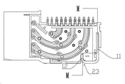
도 1은 본 발명에 따른 전기 커넥터의 구체적인 실시예 1의 구조 개략도이다.
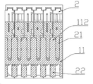
도 2는 본 발명에 따른 전기 커넥터의 구체적인 실시예 1의 정면도이다.
도 3은 도 2 중 M-M을 따른 단면도이다.
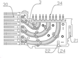
도 4는 본 발명에 따른 전기 커넥터의 구체적인 실시예 1의 고정판의 구조 개략도이다.
도 5는 본 발명에 따른 전기 커넥터의 구체적인 실시예 1의 접촉부재 고정판의 정면도이다.
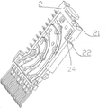
도 6은 본 발명에 따른 전기 커넥터의 구체적인 실시예 1의 접촉부재 고정판의 축측 투영도이다.
도 7은 본 발명에 따른 전기 커넥터의 구체적인 실시예 1의 만곡형 접촉부재의 구조 개략도이다.1 is a structural schematic view of a first embodiment of an electrical connector according to the present invention.
2 is a front view of a specific example 1 of an electrical connector according to the present invention.
3 is a sectional view along the line MM in Fig.
4 is a structural schematic view of the fixing plate of the first embodiment of the electrical connector according to the present invention.
5 is a front view of the contact member fixing plate of the first embodiment of the electrical connector according to the present invention.
6 is an axial side projected view of the contact member fixing plate of the first embodiment of the electrical connector according to the present invention.
7 is a structural schematic view of the curved contact member of the first embodiment of the electrical connector according to the present invention.
이하, 도면을 결부하여 본 발명의 실시형태를 더 설명한다.Hereinafter, embodiments of the present invention will be further described with reference to the drawings.
본 발명에 따른 전기 커넥터의 구체적인 실시예 1은 도 1 내지 도 7에 나타낸 바와 같다. 전기 커넥터는 좌우로 나란히 설치된 6개의 신호 모듈을 포함하고, 신호 모듈은 만곡형 접촉부재(3) 및 만곡형 접촉부재(3)를 장착하기 위한 접촉부재 장착판(2)을 포함하며, 만곡형 접촉부재(3)의 일단은 인쇄기판에 용접되는 용접다리(34)이고, 타단은 삽입 연결단(30)이다. 전기 커넥터의 선단은 삽입 연결단이고, 전기 커넥터의 선단면은 만곡형 접촉부재의 삽입 연결단이 설치되는 접촉부재 삽입 연결단 장착면이며, 저면은 만곡형 접촉부재의 용접다리를 장착하기 위한 용접다리 장착면이다.A specific embodiment 1 of the electrical connector according to the present invention is shown in Figs. 1 to 7. Fig. The electrical connector includes six signal modules arranged side by side and the signal module includes a contact member mounting plate (2) for mounting the curved contact member (3) and the curved contact member (3), and the curved contact member One end of the
전기 커넥터는 접촉부재 장착판에 끼워져 접촉부재 장착판을 고정하는 고정용 만곡 부재(1)를 포함한다. 본 실시예에서 고정용 만곡 부재는 판형 구조체이고, 고정용 만곡 부재는 전기 커넥터 상부에 고정되는 제1 부분(12), 전기 커넥터의 하측 테일부에 고정되는 제2 부분(11), 및 제1 부분과 제2 부분을 연결하는 연결 부분(13)을 포함하고, 제1 부분과 제2 부분은 연결 부분의 동일측을 향해 연장된다. 연결 부분은 전기 커넥터의 상부에 설치되고, 전기 커넥터의 상부에는 제1 부분이 삽입 고정되는 상부 함몰 삽입홈이 형성되며, 제1 부분이 상부 함몰 삽입홈 내에 삽입 고정됨으로써 제1 부분이 전기 커넥터의 상부에 설치된다.The electrical connector includes a fixing curved member (1) fitted to the contact member mounting plate to fix the contact member mounting plate. In this embodiment, the fixing curved member is a plate-like structure, and the fixing curved member has a
본 실시예에서, 제1 부분과 제2 부분은 수직 방향으로 서로 대향하여 평행으로 형성되고, 제1 부분의 길이는 제2 부분의 길이보다 작아, 상부 함몰 삽입홈이 전기 커넥터 내부의 만곡형 접촉부재와 간섭하는 것을 피한다. 제2 부분(11)은 제1 부분(12)에 가까운 제2 부분의 내측면(114)을 구비하고, 제1 부분(12)은 제2 부분에 가까운 제1 부분의 내측면(124)을 구비하며, 제2 부분의 내측면(114)은 전기 커넥터의 후단면과 가압적으로 결합한다.In the present embodiment, the first portion and the second portion are formed in parallel to face each other in the vertical direction, and the length of the first portion is smaller than the length of the second portion, Avoid interference with members. The
제2 부분(11)에 있어서 연결 부분(13)으로부터 먼 단부는 좌우로 나란히 형성된 U형 제2 부분 걸림홈(111)을 구비하고, 전기 커넥터 테일부의 후측면에는 제2 부분 걸림홈(111)에 긴밀히 걸리는 테일부 걸림 블록(21)을 구비하며, 테일부 걸림 블록(21)과 제2 부분 걸림홈(111)은 일일이 대응된다. 테일부 걸림 블록(21)은 접촉부재 장착판의 선단면 중 좌우 방향의 중간 위치에 형성된다. 서로 인접한 제2 부분 걸림홈 사이의 홈 벽은 제2 부분 플러그(112)를 구성하고, 서로 인접한 2개의 테일부 걸림 블록(21) 사이에는 제2 부분 플러그가 삽입되어 제2 부분 플러그와 긴밀히 걸리는 제2 부분 플러그 홈이 구비된다.The
상부 함몰 삽입홈(23)의 후측은 제1 부분의 내측면(124)과 가압적으로 밀착하는 함몰 삽입홈의 후측면을 구비하고, 고정용 만곡 부재(1)의 제1 부분(12)은 상부 함몰 삽입홈(23) 내에 삽입되며, 제2 부분(11)과 제1 부분(12)은 접촉부재 장착판에 끼워져 지지된다. 제2 부분(11)과 전기 커넥터 테일부의 단면이 가압적으로 결합하고, 제1 부분(12)과 상부 함몰 삽입홈(23)의 후측면이 가압적으로 결합함으로써, 고정용 만곡 부재(1)가 접촉부재 장착판(2)에 끼워져 지지되어 접촉부재 장착판을 고정하는 목적을 이룬다.The rear side of the upper recessed insertion groove 23 has a rear side of the recessed insertion groove which is in press contact with the
고정용 만곡 부재(1)의 제1 부분(12)에는 좌우로 나란히 형성된 U형의 제1 부분 걸림홈(121)이 형성되고, 서로 인접한 2개의 제1 부분 걸림홈(121) 사이의 홈 벽은 제1 부분 플러그(122)를 구성한다. 상부 함몰 삽입홈(23) 내에는 제1 부분 걸림홈(121)과 일일이 대응하여 긴밀하게 끼워 결합되는 상부 걸림 블록(22)이 형성된다. 본 실시예에서, 상부 함몰 삽입홈(23)은 각 접촉부재 장착판의 상단면에 개설된 접촉부재 장착판의 오목홈(24)이 조합되어 이루어지며, 상부 걸림 블록(22)은 접촉부재 장착판의 오목홈(24) 내에 형성된다. 서로 인접한 2개의 접촉부재 장착판의 오목홈(24)의 상부 걸림 블록(22) 사이에는 제1 부분 플러그(122)가 삽입되는 제1 부분 플러그 홈(121)이 구비되며, 제1 부분 플러그(122)는 제1 부분 플러그 홈(121)에 긴밀하게 걸린다. 제2 부분 걸림홈의 노치에는 테일부 걸림 블록이 편리하게 삽입되도록 하는 확장 구조부가 형성되고, 제1 부분 걸림홈의 노치에도 상부 걸림 블록이 편리하게 삽입되도록 하는 확장 구조부가 형성된다. 제2 부분 걸림홈의 좌우 측벽 각각에는 전후 방향으로 연장되어 테일부 걸림 블록과 긴밀하게 끼워 결합되는 제1 돌기(113)가 형성된다. 제1 부분 걸림홈의 좌우 측벽 각각에는 전후 방향으로 연장되어 상부 걸림 블록과 긴밀하게 끼워 결합되는 제2 돌기(123)가 형성된다.The
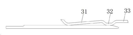
만곡형 접촉부재의 선단은 삽입 연결단이며, 삽입 연결부(31), 오목부(32) 및 삽입 연결부의 후방에 연결된 수평 방향의 장착부(33)를 포함한다. 삽입 연결부(31), 오목부(32)와 장착부(33)는 앞으로부터 뒤로의 방향으로 순차적으로 형성된다. 여기서 삽입 연결부(31)의 선단 부위는 위로 절곡된 플랜지를 구비하고, 플랜지의 만곡 부분의 하측면은 적응적 접촉부재(适配接件)와 접촉하는 전방 접촉부를 형성한다. 본 실시예에서, 오목부(32)는 U형을 나타내고 삽입 연결부(31)의 후단에 대해 아래로 함몰되며, 그 하측면은 접촉부재의 후방 접촉부를 형성한다. 장착부(33)는 수평 방향으로 오목부(32)의 후단에 위치한다. 삽입 연결부(31)는 오목부(32)와의 연결 부위로부터 뒤로부터 앞으로의 방향으로 점착 아래로 경사진다. 본 실시예에서, 전방 및 후방 접촉부는 동일한 수평면에 위치한다. 사용 시, 전방 접촉부는 적응적 접촉부재의 기저부와 탄성적으로 접촉할 수 있으며, 후방 접촉부는 적응적 접촉부재의 단부와 탄성적으로 접촉할 수 있다. 이로써, 적응적 접촉부재의 서스펜핑 구조를 소거하거나 축소시켜 상응한 커넥터의 삽입 손실을 저감시킬 수 있다.The distal end of the curved contact member is an insertion connecting end and includes a horizontal connecting
본 발명에 따른 전기 커넥터의 고정용 만곡 부재의 제2 부분과 전기 커넥터의 후단면이 가압적으로 결합하고 제1 부분과 함몰 삽입홈의 후측면이 가압적으로 결합함으로써, 고정용 만곡 부재가 제2 부분과 제1 부분에 의해 전기 커넥터에 끼워져 지지되며, 전기 커넥터의 접촉부재 장착판이 전후 방향에서 상대적으로 변위하지 않는다. 또한, 제2 부분에 형성된 제2 부분 걸림홈과 전기 커넥터 후단면 상의 테일부 걸림 블록이 좌우 방향으로 긴밀하게 걸림으로써, 접촉부재 장착판과 고정용 만곡 부재가 좌우로 상대적으로 이동하지 않도록 할 수 있다. 종래의 전기 커넥터가 단일면의 고정용 만곡 부재에 의해 접촉부재 장착판을 고정하는 것에 비해, 본 발명에 따른 고정용 만곡 부재는 전기 커넥터의 접촉부재 장착판과의 접촉 면적을 증가시킬 뿐만 아니라, 접촉부재 장착판에 대한 고정용 만곡 부재의 고정 견고도를 향상한다. 또한 고정용 만곡 부재의 제1 부분과 제2 부분을 전기 커넥터 상부와 전기 커넥터 테일부에 고정하고, 제1 부분을 상부 함몰 삽입홈에 고정함으로써, 고정의 견고도를 확보하여 전기 커넥터의 두 면을 고정한다. 고정용 만곡 부재의 제1 부분, 제2 부분과 연결 부분은 서로 협동하여 서로 인접한 접촉부재 장착판이 쉽게 변형하지 않도록 한다. 한편, 종래의 전기 커넥터 고정 시트는 수직 방향에서 모두 테일부 걸림 블록을 회피하는 일정한 회피 행정을 마련해야 하고, 수평 삽입 후 다시 수직으로 일정 거리로 밀어 고정해야 한다. 본 발명에 따른 고정용 만곡 부재는 사용 시, 바로 전기 커넥터의 상부로부터 삽입할 수 있어, 부피의 최소화를 구현하고, 다시 수직 방향으로 회피하는 행정이 필요하지 않다.The second portion of the fixing curling member of the electrical connector according to the present invention and the rear end surface of the electrical connector are press-fitted and the first portion and the rear surface of the recessed insertion groove are press-fitted together, 2 and the first portion, and the contact member mounting plate of the electrical connector is not displaced relatively in the front-rear direction. In addition, since the second part engaging groove formed in the second portion and the partly engaging block on the end surface of the electrical connector are tightly engaged in the left and right direction, the contact member mounting plate and the fixing curved member can be prevented from moving relative to each other have. The fixing curved member according to the present invention not only increases the contact area of the electrical connector with the contact member mounting plate but also reduces the contact area between the contact member mounting plate and the contact member mounting plate, Thereby improving the fixing rigidity of the fixing curved member relative to the contact member mounting plate. Also, by securing the first and second portions of the fixing curved member to the upper portion of the electrical connector and the electrical connector frame portion and fixing the first portion to the upper recessed insertion groove, . The first portion, the second portion and the connecting portion of the fixing curved member cooperate with each other to prevent the contact member mounting plates adjacent to each other from being easily deformed. On the other hand, the conventional electric connector fixing sheet has to be provided with a constant avoidance stroke to avoid the tether interlocking block in all directions in the vertical direction, and to be fixed by pushing it vertically a certain distance again after horizontally inserting. The fixing curved member according to the present invention can be inserted directly from the top of the electrical connector at the time of use so that a minimization of the volume is realized and a stroke avoiding again in the vertical direction is not required.
본 발명에 따른 전기 커넥터의 구체적인 실시예 2는 아래 면에서만 상기 실시예 1과 서로 다르다. 연결 부분은 전기 커넥터 테일부에 설치되고, 상부 함몰 삽입홈이 형성되지 않으며, 제1 부분은 전기 커넥터 상부 단면에 형성된 상부 걸림 블록과 긴밀하게 걸리며, 전기 커넥터의 테일부에는 테일부 함몰 삽입홈이 형성되고, 테일부 걸림 블록이 함몰 삽입홈 내에 설치된다.The second embodiment of the electrical connector according to the present invention is different from the first embodiment only on the lower surface. The connector portion is provided in the electrical connector frame portion, and the upper portion recessed groove is not formed. The first portion is tightly engaged with the upper connector block formed in the upper end surface of the electrical connector, And a plurality of retaining blocks are provided in the recessed insertion grooves.
본 발명에 따른 전기 커넥터의 구체적인 실시예 3은 아래 면에서만 상기 실시예 1과 서로 다르다. 상부 함몰 삽입홈 내에는 상부 걸림 블록이 형성되지 않고, 제1 부분이 상부 함몰 삽입홈 내에 가압됨으로써 제1 부분이 전기 커넥터 상부에 고정된다. 제1 부분은 상부 함몰 삽입홈의 전측면 또는 후측면에 가압될 수 있다.The third embodiment of the electrical connector according to the present invention is different from the first embodiment only on the lower surface. The first engaging block is not formed in the upper recessed insertion groove and the first portion is pressed into the upper recessed insertion groove to fix the first portion to the upper portion of the electrical connector. The first portion can be pressed to the front or rear side of the upper recessed insertion groove.
본 발명에 따른 고정용 만곡 부재의 구체적인 실시예에서 상기 고정용 만곡 부재는 상기 전기 커넥터의 구체적인 실시예 1, 실시예 2 또는 실시예 3에 따른 고정용 만곡 부재의 구조와 같으므로 더 이상 설명하지 않는다.In a specific embodiment of the fixing curved member according to the present invention, the fixing curved member is the same as the structure of the fixing curved member according to the first, second or third embodiment of the electrical connector, Do not.
본 발명에 따른 전기 커넥터 및 그 고정용 만곡 부재의 다른 실시예에서는, 상기 제1 부분과 제2 부분의 걸림홈에 형성된 돌기를 형성하지 않을 수 있으며, 별도로 삽입홈과 긴밀하게 끼워 결합되는 돌출 블록의 표면에 돌기 구조부를 형성하거나, 또는 확장 형태를 이용하여 제1 부분과 제2 부분의 걸림홈과 이에 대응하는 걸림 블록이 억지 결합되도록 할 수 있다. 상기 상부 걸림 블록은 2개의 제1 부분 플러그에 대응할 수 있으며, 이때 대응된 2개의 제1 부분 플러그 사이의 제1 부분 걸림홈은 좌우 방향으로 나란히 형성되지 않고, 전후 방향으로 일정한 이격 거리를 둘 수 있다.In another embodiment of the electrical connector and the fixing curved member according to the present invention, the protrusion formed on the engagement groove of the first portion and the second portion may not be formed, and the protrusion block Or by using the extended shape, the engaging grooves of the first and second portions and the corresponding engaging blocks can be forcedly engaged with each other. The upper latching block may correspond to the two first partial plugs. In this case, the first partial latching grooves between the two first partial plugs are not formed side by side in the lateral direction, have.
Claims (14)
접촉부재 장착판을 고정하기 위한 고정용 만곡 부재를 더 포함하고, 고정용 만곡 부재는 전기 커넥터 상부에 고정되는 제1 부분, 전기 커넥터 테일부에 고정되는 제2 부분, 및 제1 부분과 제2 부분을 연결하는 연결 부분을 포함하며, 제1 부분과 제2 부분은 연결 부분의 동일측을 향해 연장되며, 연결 부분은 전기 커넥터 상부에 설치되고 상기 전기 커넥터 상부에는 제1 부분이 전기 커넥터 상부에 고정되도록 제1 부분을 삽입 고정하는 상부 함몰 삽입홈이 형성되거나, 또는 연결 부분은 전기 커넥터 테일부에 설치되고 상기 전기 커넥터 테일부에는 상기 제2 부분이 전기 커넥터 테일부에 고정되도록 제2 부분을 삽입 고정하는 테일부 함몰 삽입홈이 형성되는, 전기 커넥터.An electrical connector comprising: a contact member whose tip is an insertion connecting end; and at least two contact member mounting plates which are arranged side by side and extend in the longitudinal direction,
Wherein the fixing curved member further comprises a first portion fixed to the upper portion of the electrical connector, a second portion fixed to the electrical connector portion, and a second portion fixed to the first portion and the second portion, Wherein the first portion and the second portion extend toward the same side of the connection portion, the connection portion is disposed on the upper portion of the electrical connector, and the first portion is disposed on the upper portion of the electrical connector on the upper portion of the electrical connector An upper recessed insertion groove for inserting and fixing the first portion to be fixed to the electrical connector frame portion is formed or a connecting portion is provided in the electrical connector frame portion and the second portion is fixed to the electrical connector frame portion, And a plurality of tapered recessed insertion grooves are formed.
연결 부분은 전기 커넥터 상부에 설치되고, 상기 전기 커넥터 상부에는 제1 부분이 전기 커넥터 상부에 고정되도록 제1 부분을 삽입 고정하는 상부 함몰 삽입홈이 형성되는, 전기 커넥터.The method according to claim 1,
And an upper recessed insertion groove is formed in the upper portion of the electrical connector so that the first portion is fixed to the upper portion of the electrical connector.
상기 제1 부분은 상부 함몰 삽입홈의 전측면 또는 후측면에 가압되는, 전기 커넥터.3. The method of claim 2,
And the first portion is pressed to the front side or rear side of the upper recessed insertion groove.
상기 제1 부분과 상부 함몰 삽입홈의 후측면이 서로 긴밀하게 가압하고 제2 부분과 전기 커넥터 테일부의 단면이 서로 긴밀하게 가압함으로써 고정용 만곡 부재를 접촉부재 장착판에 끼움 설치하는, 전기 커넥터.The method of claim 3,
The first portion and the rear surface of the upper depression insertion groove are pressed tightly with each other, and the end surface of the second portion and the electrical connector tail portion are pressed tightly with each other, thereby fitting the fixing curved member into the contact member mounting plate.
각각의 접촉부재 장착판 각각에는 상부 함몰 삽입홈 내에 위치하는 상부 걸림 블록이 형성되며, 상기 제1 부분에는 상부 걸림 블록과 대응하는 제1 부분 플러그가 형성되고, 서로 인접한 제1 부분 플러그 사이에는 상부 걸림 블록이 긴밀하게 걸리는 제1 부분 걸림홈이 형성되며,
각각의 접촉부재 장착판 각각에는 전기 커넥터 테일부에 위치하는 테일부 걸림 블록이 형성되며, 상기 제2 부분에는 테일부 걸림 블록과 대응하는 제2 부분 플러그가 형성되고, 서로 인접한 제2 부분 플러그 사이에는 테일부 걸림 블록이 긴밀하게 걸리는 제2 부분 걸림홈이 형성되는, 전기 커넥터.5. The method according to any one of claims 2 to 4,
Each of the contact member mounting plates is provided with an upper latch block located in the upper recessed insertion groove, wherein a first partial plug corresponding to the upper latch block is formed in the first portion, A first part engaging groove is formed in which the engaging block is tightly engaged,
Each of the contact member mounting plates is provided with a tab engagement block located in the electrical connector frame portion, a second partial plug corresponding to the tail portion locking block is formed in the second portion, Wherein the second part latching groove is formed so that the second latching block is tightly engaged with the second latching block.
상기 서로 인접한 상부 걸림 블록 사이에는 제1 부분 플러그와 긴밀하게 걸림 결합되는 상부 걸림홈이 형성되고, 또한/또는 서로 인접한 테일부 걸림 블록 사이에는 제2 부분 플러그와 긴밀하게 걸림 결합되는 테일부 걸림홈이 형성되는, 전기 커넥터.6. The method of claim 5,
An upper latching groove is formed between the adjacent upper latching blocks so as to be tightly engaged with the first partial plug, and / or between the lower latching blocks adjacent to each other, Is formed.
상기 제1 부분 플러그와 제2 부분 플러그에는 걸림 블록과 긴밀하게 걸림 결합되는 돌기가 형성되는, 전기 커넥터.The method according to claim 6,
Wherein the first partial plug and the second partial plug are formed with projections which are tightly engaged with the latch block.
연결 부분은 전기 커넥터 테일부에 설치되고, 상기 전기 커넥터 테일부에는 제2 부분이 전기 커넥터 테일부에 고정되도록 제2 부분을 삽입 고정하는 테일부 함몰 삽입홈이 형성되는, 전기 커넥터.The method according to claim 1,
Wherein the connecting portion is provided in the electric connector frame portion and the electric connector frame portion is formed with a tapered portion inserting groove for inserting and fixing the second portion so that the second portion is fixed to the electric connector frame portion.
상기 제2 부분은 테일부 함몰 삽입홈의 상측면 또는 하측면에 가압되는, 전기 커넥터.9. The method of claim 8,
And the second portion is pressed to the upper or lower side of the tapered depression insertion groove.
상기 제2 부분과 테일부 함몰 삽입홈의 상측면이 서로 긴밀하게 가압하고 제1 부분과 전기 커넥터 상부 단면이 서로 긴밀하게 가압함으로써 고정용 만곡 부재를 접촉부재 장착판에 끼움 설치하는, 전기 커넥터.10. The method of claim 9,
Wherein the second portion and the upper surface of the tapered depression insertion groove are pressed tightly with each other and the first portion and the upper surface of the electrical connector are pressed tightly with each other to fit the fixing curved member into the contact member mounting plate.
각각의 접촉부재 장착판 각각에는 테일부 함몰 삽입홈 내에 위치하는 테일부 걸림 블록이 형성되며, 상기 제2 부분에는 테일부 걸림 블록과 대응하는 제2 부분 플러그가 형성되고, 서로 인접한 제2 부분 플러그 사이에는 테일부 걸림 블록이 긴밀하게 걸리는 제2 부분 걸림홈이 형성되며,
각각의 접촉부재 장착판 각각에는 전기 커넥터 상부에 위치하는 상부 걸림 블록이 형성되며, 상기 제1 부분에는 상부 걸림 블록과 대응하는 제1 부분 플러그가 형성되고, 서로 인접한 제1 부분 플러그 사이에는 상부 걸림 블록이 긴밀하게 걸리는 제1 부분 걸림홈이 형성되는, 전기 커넥터.11. The method according to any one of claims 8 to 10,
Each of the contact member mounting plates is provided with a frame part locking block located in the frame part depression insertion groove, a second partial plug corresponding to the frame part locking block is formed in the second part, A second part engaging groove in which a part of the engaging block is tightly engaged is formed,
Each of the contact member mounting plates is provided with an upper latch block located on the upper portion of the electrical connector, a first partial plug corresponding to the upper latch block is formed in the first portion, And a first part latching groove is formed in which the block is tightly engaged.
상기 접촉부재는 삽입 연결부 및 삽입 연결부의 후방에 위치한 수평 방향의 장착부를 포함하고, 삽입 연결부의 선단 머리부는 위로 만곡되어 형성된 플랜지를 구비하며, 플랜지의 만곡 부분의 하측면은 적응적 접촉부재(适配接件)와 접촉하는 전방 접촉부를 형성하며, 삽입 연결부와 장착부 사이에는 삽입 연결부의 후단에 대해 아래로 함몰된 하나의 오목부가 구비되며, 오목부는 접촉부재의 후방 접촉부를 형성하며, 상기 접촉부는 나머지 오목부의 연결 부위로부터 뒤로부터 앞으로의 방향으로 점차 아래로 경사지는, 전기 커넥터.5. The method according to any one of claims 1 to 4,
Wherein the contact member includes a horizontal mounting portion located at the rear of the insertion connection portion and the insertion connection portion, the tip end portion of the insertion connection portion has a flange formed to be curved upward, and a lower side surface of the curved portion of the flange is an adaptive contact member Wherein the recess is formed with a concave portion which is depressed downwardly with respect to a rear end of the insertion connection portion, the recess portion forms a rear contact portion of the contact member, and the contact portion And gradually inclined downward from a backward direction to a forward direction from a connecting portion of the remaining recess.
상기 제1 부분에는 상부 걸림 블록과 대응하는 제1 부분 플러그가 형성되고, 서로 인접한 제1 부분 플러그 사이에는 상부 걸림 블록이 긴밀하게 걸리는 제1 부분 걸림홈이 형성되며, 상기 제2 부분에는 테일부 걸림 블록과 대응하는 제2 부분 플러그가 형성되고, 서로 인접한 제2 부분 플러그 사이에는 테일부 걸림 블록이 긴밀하게 걸리는 제2 부분 걸림홈이 형성되거나, 또는,
상기 제1 부분에는 테일부 걸림 블록과 대응하는 제1 부분 플러그가 형성되고, 서로 인접한 제1 부분 플러그 사이에는 테일부 걸림 블록이 긴밀하게 걸리는 제1 부분 걸림홈이 형성되며, 상기 제2 부분에는 상부 걸림 블록과 대응하는 제2 부분 플러그가 형성되고, 서로 인접한 제2 부분 플러그 사이에는 상부 걸림 블록이 긴밀하게 걸리는 제2 부분 걸림홈이 형성되는, 고정용 만곡 부재.14. The method of claim 13,
A first partial plug corresponding to the upper latch block is formed in the first portion, a first partial latching groove in which the upper latch block is tightly engaged is formed between the first partial plugs adjacent to each other, The second partial plugs corresponding to the latch blocks are formed and the second partial latching grooves are formed between the second partial plugs adjacent to each other to tightly engage the partial latching blocks,
A first part plug corresponding to the frame part locking block is formed in the first part and a first part engaging groove in which a frame part locking block is tightly engaged is formed between the adjacent first part plugs, Wherein a second partial plug corresponding to the upper catch block is formed, and a second partial catching groove is formed between the second partial plugs adjacent to each other so that the upper catch block tightly engages.
Applications Claiming Priority (3)
| Application Number | Priority Date | Filing Date | Title |
|---|---|---|---|
| CN201610610605.1 | 2016-07-29 | ||
| CN201610610605.1A CN106252968B (en) | 2016-07-29 | 2016-07-29 | Electric connector |
| PCT/CN2017/077477 WO2018018899A1 (en) | 2016-07-29 | 2017-03-21 | Electrical connector and fixing bending member thereof |
Publications (2)
| Publication Number | Publication Date |
|---|---|
| KR20180098399A true KR20180098399A (en) | 2018-09-03 |
| KR102153481B1 KR102153481B1 (en) | 2020-09-08 |
Family
ID=57604786
Family Applications (1)
| Application Number | Title | Priority Date | Filing Date |
|---|---|---|---|
| KR1020187021963A Active KR102153481B1 (en) | 2016-07-29 | 2017-03-21 | Electrical connector and curved member for fixing the same |
Country Status (6)
| Country | Link |
|---|---|
| US (1) | US10608367B2 (en) |
| EP (1) | EP3407433B8 (en) |
| JP (1) | JP6781763B2 (en) |
| KR (1) | KR102153481B1 (en) |
| CN (1) | CN106252968B (en) |
| WO (1) | WO2018018899A1 (en) |
Families Citing this family (5)
| Publication number | Priority date | Publication date | Assignee | Title |
|---|---|---|---|---|
| CN106252968B (en) * | 2016-07-29 | 2019-06-07 | 中航光电科技股份有限公司 | Electric connector |
| USD926701S1 (en) * | 2019-05-31 | 2021-08-03 | Starconn Electronic (Su Zhou) Co., Ltd | Electrical connector |
| CN110783756A (en) * | 2019-09-23 | 2020-02-11 | 中航光电科技股份有限公司 | A mixed printed board connector |
| WO2021174478A1 (en) * | 2020-03-05 | 2021-09-10 | 四川华丰科技股份有限公司 | Back plate connector |
| CN112952448B (en) * | 2021-01-28 | 2022-12-06 | 深圳市豪塑科技有限公司 | Connector and production process thereof |
Citations (3)
| Publication number | Priority date | Publication date | Assignee | Title |
|---|---|---|---|---|
| JP2001313112A (en) * | 1999-11-03 | 2001-11-09 | Molex Inc | Retainer for wafer connector |
| US8475209B1 (en) * | 2012-02-14 | 2013-07-02 | Tyco Electronics Corporation | Receptacle assembly |
| CN104167620A (en) * | 2013-08-29 | 2014-11-26 | 中航光电科技股份有限公司 | Bent contact member, jack module and electrical connector |
Family Cites Families (16)
| Publication number | Priority date | Publication date | Assignee | Title |
|---|---|---|---|---|
| US5993259A (en) * | 1997-02-07 | 1999-11-30 | Teradyne, Inc. | High speed, high density electrical connector |
| US6979215B2 (en) * | 2001-11-28 | 2005-12-27 | Molex Incorporated | High-density connector assembly with flexural capabilities |
| US6875031B1 (en) * | 2003-12-05 | 2005-04-05 | Hon Hai Precision Ind. Co., Ltd. | Electrical connector with circuit board module |
| US8083553B2 (en) * | 2005-06-30 | 2011-12-27 | Amphenol Corporation | Connector with improved shielding in mating contact region |
| US7503804B2 (en) | 2006-12-19 | 2009-03-17 | Fci Americas Technology Inc. | Backplane connector |
| US7497736B2 (en) * | 2006-12-19 | 2009-03-03 | Fci Americas Technology, Inc. | Shieldless, high-speed, low-cross-talk electrical connector |
| US7682193B2 (en) * | 2007-10-30 | 2010-03-23 | Fci Americas Technology, Inc. | Retention member |
| US7637767B2 (en) * | 2008-01-04 | 2009-12-29 | Tyco Electronics Corporation | Cable connector assembly |
| CN201285845Y (en) * | 2008-08-05 | 2009-08-05 | 富士康(昆山)电脑接插件有限公司 | Electric connector |
| US8366485B2 (en) * | 2009-03-19 | 2013-02-05 | Fci Americas Technology Llc | Electrical connector having ribbed ground plate |
| CN202034538U (en) * | 2011-02-26 | 2011-11-09 | 安费诺(常州)连接系统有限公司 | Wave-shaped terminal connector |
| US8662924B2 (en) | 2012-04-23 | 2014-03-04 | Tyco Electronics Corporation | Electrical connector system having impedance control |
| US9033750B2 (en) * | 2012-08-15 | 2015-05-19 | Tyco Electronics Corporation | Electrical contact |
| CN202940374U (en) * | 2012-11-13 | 2013-05-15 | 安费诺(常州)高端连接器有限公司 | Connector with anti-tilt metal support |
| WO2014134773A1 (en) * | 2013-03-04 | 2014-09-12 | 3M Innovative Properties Company | Electrical interconnection system and electrical connectors for the same |
| CN106252968B (en) * | 2016-07-29 | 2019-06-07 | 中航光电科技股份有限公司 | Electric connector |
-
2016
- 2016-07-29 CN CN201610610605.1A patent/CN106252968B/en active Active
-
2017
- 2017-03-21 WO PCT/CN2017/077477 patent/WO2018018899A1/en not_active Ceased
- 2017-03-21 EP EP17833207.8A patent/EP3407433B8/en active Active
- 2017-03-21 US US16/078,011 patent/US10608367B2/en active Active
- 2017-03-21 JP JP2018541704A patent/JP6781763B2/en active Active
- 2017-03-21 KR KR1020187021963A patent/KR102153481B1/en active Active
Patent Citations (3)
| Publication number | Priority date | Publication date | Assignee | Title |
|---|---|---|---|---|
| JP2001313112A (en) * | 1999-11-03 | 2001-11-09 | Molex Inc | Retainer for wafer connector |
| US8475209B1 (en) * | 2012-02-14 | 2013-07-02 | Tyco Electronics Corporation | Receptacle assembly |
| CN104167620A (en) * | 2013-08-29 | 2014-11-26 | 中航光电科技股份有限公司 | Bent contact member, jack module and electrical connector |
Also Published As
| Publication number | Publication date |
|---|---|
| JP6781763B2 (en) | 2020-11-04 |
| WO2018018899A1 (en) | 2018-02-01 |
| CN106252968A (en) | 2016-12-21 |
| EP3407433B8 (en) | 2022-08-03 |
| EP3407433A4 (en) | 2019-06-26 |
| KR102153481B1 (en) | 2020-09-08 |
| CN106252968B (en) | 2019-06-07 |
| EP3407433A1 (en) | 2018-11-28 |
| JP2019505079A (en) | 2019-02-21 |
| US10608367B2 (en) | 2020-03-31 |
| EP3407433B1 (en) | 2022-06-29 |
| US20190260152A1 (en) | 2019-08-22 |
Similar Documents
| Publication | Publication Date | Title |
|---|---|---|
| KR20180098399A (en) | Electrical connector and fixing member therefor | |
| KR101815093B1 (en) | Electric connector for circuit board | |
| CN102347553B (en) | Electric connector for circuit substrate | |
| KR101364231B1 (en) | Connector | |
| JP3150862U (en) | Electrical connector | |
| JP2009140678A (en) | Female terminal bracket for PCB | |
| KR20150051997A (en) | Connector | |
| JP5548308B2 (en) | connector | |
| JP6251500B2 (en) | connector | |
| CN102868056B (en) | floating connector | |
| CN204793436U (en) | Electrical connector assembly | |
| KR20160001646U (en) | Connector socket | |
| US11271349B2 (en) | Electrical connector with stop positioned on metallic shell | |
| JP2015176657A (en) | connector | |
| KR101514372B1 (en) | Connector | |
| JP2019117692A (en) | L-shaped electric connector for circuit board and manufacturing method thereof | |
| JP2005222771A (en) | Connector for base plate | |
| US10566743B2 (en) | Electrical connector having a middle shielding plate and an outer shielding shell with grounding legs held in place by the shielding plate | |
| TWM495648U (en) | Electrical connector | |
| US20120264323A1 (en) | Board connector | |
| JP2012018781A (en) | Connector | |
| CN203326218U (en) | Stacked electric connector | |
| JP5203099B2 (en) | Vertical SMT connector | |
| US10559900B2 (en) | Board connector with tool installation space for beding a terminal fitting | |
| JP2009059672A (en) | Electrical connector |
Legal Events
| Date | Code | Title | Description |
|---|---|---|---|
| A201 | Request for examination | ||
| AMND | Amendment | ||
| P11-X000 | Amendment of application requested |
St.27 status event code: A-2-2-P10-P11-nap-X000 |
|
| P13-X000 | Application amended |
St.27 status event code: A-2-2-P10-P13-nap-X000 |
|
| PA0105 | International application |
St.27 status event code: A-0-1-A10-A15-nap-PA0105 |
|
| PA0201 | Request for examination |
St.27 status event code: A-1-2-D10-D11-exm-PA0201 |
|
| PG1501 | Laying open of application |
St.27 status event code: A-1-1-Q10-Q12-nap-PG1501 |
|
| E902 | Notification of reason for refusal | ||
| PE0902 | Notice of grounds for rejection |
St.27 status event code: A-1-2-D10-D21-exm-PE0902 |
|
| AMND | Amendment | ||
| E13-X000 | Pre-grant limitation requested |
St.27 status event code: A-2-3-E10-E13-lim-X000 |
|
| P11-X000 | Amendment of application requested |
St.27 status event code: A-2-2-P10-P11-nap-X000 |
|
| P13-X000 | Application amended |
St.27 status event code: A-2-2-P10-P13-nap-X000 |
|
| E601 | Decision to refuse application | ||
| PE0601 | Decision on rejection of patent |
St.27 status event code: N-2-6-B10-B15-exm-PE0601 |
|
| X091 | Application refused [patent] | ||
| AMND | Amendment | ||
| P11-X000 | Amendment of application requested |
St.27 status event code: A-2-2-P10-P11-nap-X000 |
|
| P13-X000 | Application amended |
St.27 status event code: A-2-2-P10-P13-nap-X000 |
|
| PX0901 | Re-examination |
St.27 status event code: A-2-3-E10-E12-rex-PX0901 |
|
| PX0701 | Decision of registration after re-examination |
St.27 status event code: A-3-4-F10-F13-rex-PX0701 |
|
| X701 | Decision to grant (after re-examination) | ||
| GRNT | Written decision to grant | ||
| PR0701 | Registration of establishment |
St.27 status event code: A-2-4-F10-F11-exm-PR0701 |
|
| PR1002 | Payment of registration fee |
St.27 status event code: A-2-2-U10-U12-oth-PR1002 Fee payment year number: 1 |
|
| PG1601 | Publication of registration |
St.27 status event code: A-4-4-Q10-Q13-nap-PG1601 |
|
| R18-X000 | Changes to party contact information recorded |
St.27 status event code: A-5-5-R10-R18-oth-X000 |
|
| PR1001 | Payment of annual fee |
St.27 status event code: A-4-4-U10-U11-oth-PR1001 Fee payment year number: 4 |
|
| PR1001 | Payment of annual fee |
St.27 status event code: A-4-4-U10-U11-oth-PR1001 Fee payment year number: 5 |
|
| R18-X000 | Changes to party contact information recorded |
St.27 status event code: A-5-5-R10-R18-oth-X000 |
|
| PR1001 | Payment of annual fee |
St.27 status event code: A-4-4-U10-U11-oth-PR1001 Fee payment year number: 6 |
|
| U11 | Full renewal or maintenance fee paid |
Free format text: ST27 STATUS EVENT CODE: A-4-4-U10-U11-OTH-PR1001 (AS PROVIDED BY THE NATIONAL OFFICE) Year of fee payment: 6 |