KR20180098346A - Synchronous cylinder for extrusion equipment - Google Patents
Synchronous cylinder for extrusion equipment Download PDFInfo
- Publication number
- KR20180098346A KR20180098346A KR1020187021301A KR20187021301A KR20180098346A KR 20180098346 A KR20180098346 A KR 20180098346A KR 1020187021301 A KR1020187021301 A KR 1020187021301A KR 20187021301 A KR20187021301 A KR 20187021301A KR 20180098346 A KR20180098346 A KR 20180098346A
- Authority
- KR
- South Korea
- Prior art keywords
- cylinder
- bypass
- synchronizing
- pressure chambers
- outer cylinder
- Prior art date
- Legal status (The legal status is an assumption and is not a legal conclusion. Google has not performed a legal analysis and makes no representation as to the accuracy of the status listed.)
- Granted
Links
Images


Classifications
-
- F—MECHANICAL ENGINEERING; LIGHTING; HEATING; WEAPONS; BLASTING
- F15—FLUID-PRESSURE ACTUATORS; HYDRAULICS OR PNEUMATICS IN GENERAL
- F15B—SYSTEMS ACTING BY MEANS OF FLUIDS IN GENERAL; FLUID-PRESSURE ACTUATORS, e.g. SERVOMOTORS; DETAILS OF FLUID-PRESSURE SYSTEMS, NOT OTHERWISE PROVIDED FOR
- F15B15/00—Fluid-actuated devices for displacing a member from one position to another; Gearing associated therewith
- F15B15/08—Characterised by the construction of the motor unit
- F15B15/14—Characterised by the construction of the motor unit of the straight-cylinder type
- F15B15/149—Fluid interconnections, e.g. fluid connectors, passages
-
- F—MECHANICAL ENGINEERING; LIGHTING; HEATING; WEAPONS; BLASTING
- F15—FLUID-PRESSURE ACTUATORS; HYDRAULICS OR PNEUMATICS IN GENERAL
- F15B—SYSTEMS ACTING BY MEANS OF FLUIDS IN GENERAL; FLUID-PRESSURE ACTUATORS, e.g. SERVOMOTORS; DETAILS OF FLUID-PRESSURE SYSTEMS, NOT OTHERWISE PROVIDED FOR
- F15B11/00—Servomotor systems without provision for follow-up action; Circuits therefor
- F15B11/16—Servomotor systems without provision for follow-up action; Circuits therefor with two or more servomotors
- F15B11/22—Synchronisation of the movement of two or more servomotors
-
- F—MECHANICAL ENGINEERING; LIGHTING; HEATING; WEAPONS; BLASTING
- F15—FLUID-PRESSURE ACTUATORS; HYDRAULICS OR PNEUMATICS IN GENERAL
- F15B—SYSTEMS ACTING BY MEANS OF FLUIDS IN GENERAL; FLUID-PRESSURE ACTUATORS, e.g. SERVOMOTORS; DETAILS OF FLUID-PRESSURE SYSTEMS, NOT OTHERWISE PROVIDED FOR
- F15B13/00—Details of servomotor systems ; Valves for servomotor systems
- F15B13/02—Fluid distribution or supply devices characterised by their adaptation to the control of servomotors
- F15B13/021—Valves for interconnecting the fluid chambers of an actuator
-
- F—MECHANICAL ENGINEERING; LIGHTING; HEATING; WEAPONS; BLASTING
- F15—FLUID-PRESSURE ACTUATORS; HYDRAULICS OR PNEUMATICS IN GENERAL
- F15B—SYSTEMS ACTING BY MEANS OF FLUIDS IN GENERAL; FLUID-PRESSURE ACTUATORS, e.g. SERVOMOTORS; DETAILS OF FLUID-PRESSURE SYSTEMS, NOT OTHERWISE PROVIDED FOR
- F15B15/00—Fluid-actuated devices for displacing a member from one position to another; Gearing associated therewith
- F15B15/08—Characterised by the construction of the motor unit
- F15B15/14—Characterised by the construction of the motor unit of the straight-cylinder type
- F15B15/1423—Component parts; Constructional details
- F15B15/1428—Cylinders
-
- F—MECHANICAL ENGINEERING; LIGHTING; HEATING; WEAPONS; BLASTING
- F15—FLUID-PRESSURE ACTUATORS; HYDRAULICS OR PNEUMATICS IN GENERAL
- F15B—SYSTEMS ACTING BY MEANS OF FLUIDS IN GENERAL; FLUID-PRESSURE ACTUATORS, e.g. SERVOMOTORS; DETAILS OF FLUID-PRESSURE SYSTEMS, NOT OTHERWISE PROVIDED FOR
- F15B15/00—Fluid-actuated devices for displacing a member from one position to another; Gearing associated therewith
- F15B15/20—Other details, e.g. assembly with regulating devices
- F15B15/202—Externally-operated valves mounted in or on the actuator
-
- F—MECHANICAL ENGINEERING; LIGHTING; HEATING; WEAPONS; BLASTING
- F15—FLUID-PRESSURE ACTUATORS; HYDRAULICS OR PNEUMATICS IN GENERAL
- F15B—SYSTEMS ACTING BY MEANS OF FLUIDS IN GENERAL; FLUID-PRESSURE ACTUATORS, e.g. SERVOMOTORS; DETAILS OF FLUID-PRESSURE SYSTEMS, NOT OTHERWISE PROVIDED FOR
- F15B2211/00—Circuits for servomotor systems
- F15B2211/70—Output members, e.g. hydraulic motors or cylinders or control therefor
- F15B2211/705—Output members, e.g. hydraulic motors or cylinders or control therefor characterised by the type of output members or actuators
- F15B2211/7051—Linear output members
- F15B2211/7053—Double-acting output members
- F15B2211/7054—Having equal piston areas
Landscapes
- Engineering & Computer Science (AREA)
- Physics & Mathematics (AREA)
- Fluid Mechanics (AREA)
- Mechanical Engineering (AREA)
- General Engineering & Computer Science (AREA)
- Chemical & Material Sciences (AREA)
- Analytical Chemistry (AREA)
- Actuator (AREA)
- Press Drives And Press Lines (AREA)
- Fluid-Pressure Circuits (AREA)
Abstract
본 발명은 바람직하게는 압출 설비를 위한 동기 실린더(1)에 관한 것이며, 상기 동기 실린더는 외부 실린더(10)와; 상기 외부 실린더 내에 수용되어 상기 외부 실린더에 대해 동심으로 배치되는 내부 실린더(20)와; 내부 실린더 내에 변위 가능하게 제공되는 이중 작용식 작동 피스톤(41)과; 바이패스 밸브(52)를 구비한 바이패스 장치(50)를; 포함하고, 작동 피스톤(41)은 내부 실린더(20)를 2개의 압력 챔버(412)로 분할하면서 두 압력 챔버(42)로부터 유압 유체를 공급받을 수 있으며, 바이패스 장치(50)는, 바이패스 밸브(52)의 바이패스 위치에서 두 압력 챔버(42) 간의 유체 연결부가 직접 연결부, 바람직하게는 적어도 하나의 바이패스 라인을 통해 형성되고 바이패스 밸브(52)의 작업 위치에서는 상기 유체 연결부가 존재하지 않도록 구성된다.The present invention preferably relates to a synchronous cylinder (1) for an extruder, said synchronous cylinder comprising an outer cylinder (10); An inner cylinder (20) received in the outer cylinder and disposed concentrically with respect to the outer cylinder; A dual acting working piston (41) displaceably provided in the inner cylinder; A bypass device (50) having a bypass valve (52); And the operating piston 41 is capable of receiving hydraulic fluid from the two pressure chambers 42 while dividing the inner cylinder 20 into two pressure chambers 412. The bypass device 50 includes bypass The fluid connection between the two pressure chambers 42 at the bypass position of the valve 52 is formed through a direct connection, preferably at least one bypass line, and in the working position of the bypass valve 52, .
Description
본 발명은 바람직하게는 성형 장치, 특히 프레스 설비, 압출 설비 또는 링 압연 설비에서의 이용을 위한 동기 실린더에 관한 것이다.The present invention preferably relates to a synchronizing cylinder for use in a molding apparatus, particularly a press facility, an extrusion facility or a ring rolling facility.
압출 및 링 압연 설비들은 목표하는 힘 인가(force application)를 이용하여 소재들, 예컨대 예열된 중금속 또는 경금속 블록들의 소성 성형을 위한 장치들이다. 이렇게, 압출 설비의 경우, 예컨대 빌렛(billet)으로서도 지칭되는 상기 중금속 또는 경금속 블록은 유압 작동식 가압 펀치(pressing punch)에 의해 이른바 다이(die)를 통해 통과되며, 그럼으로써 정해진 소정의 프로파일을 갖는 반제품이 제조된다. 상기 압출 설비들은 예컨대 DE 38 36 702 C1호 및 DE 10 2012 009 182 A1호에서 개시된다.Extrusion and ring rolling facilities are devices for the plastic forming of materials, e.g., preheated heavy metal or light metal blocks, using a targeted force application. Thus, in the case of extrusion equipment, the heavy metal or light metal block, also referred to as a billet, is passed through a so-called die by a hydraulically actuated pressing punch, Semi-finished products are manufactured. The extrusion facilities are described, for example, in DE 38 36 702 C1 and DE 10 2012 009 182 A1.
피가공재의 성형을 위한 실질적인 힘 인가에 추가로, 상기 유형의 설비들은 전형적으로 다이 또는 다른 설비 구성요소들을 포함하는 수용 장치(receiving device)를 이송하거나 포지셔닝하기 위한 구동부들을 포함한다. 종래, 블록 수용 장치는 큰 행정(stroke)에 걸쳐 유압 실린더들에 의해 구성되어 해당 위치로 이동된다. 이처럼, 예컨대 수용 장치는, 상기 방식으로 블록 교체를 위한 위치와, 전방 단부 위치, 즉 밀봉 또는 압착, 환기 및 박리(stripping)가 수행되는 작업 위치(working position) 사이에서 이동된다. 그 대안으로, 블록 교체 위치와 작업 위치 사이에서 수용 장치를 이동시키는 전기 모터들이 이용된다.In addition to the substantial force application for the shaping of the material to be processed, the types of equipment typically include actuators for transporting or positioning a receiving device comprising a die or other component. Conventionally, a block receiving device is constituted by hydraulic cylinders over a large stroke and is moved to a corresponding position. As such, for example, the receiving device is moved in this manner between a position for block replacement and a forward position, i.e., a working position where sealing or compression, ventilation and stripping are performed. Alternatively, electric motors are used to move the receiving device between the block replacement position and the working position.
전기 모터들을 이용하는 경우, 유압 실린더들의 내부 힘이 극복되어야 한다. 이는, 특히, 자신의 구조(피스톤들, 경우에 따라서는 중공 원통형 피스톤들을 포함하여 안내되는 2개의 피스톤 로드)로 인해 유동 손실에 추가로 상대적으로 기계적인 마찰력도 극복되어야 하는 것인 동기 실린더들의 이용 시에 적용된다. 다른 한편으로, 동기 실린더들은 상기에서 논의한 성형 장치들에서 유용한데, 그 이유는 동기 실린더들이 자신들의 전체 행정에 걸쳐서 견인 모드(tow mode)에서 작업 모드(working mode)로 전환될 수 있기 때문이다.When using electric motors, the internal forces of the hydraulic cylinders must be overcome. This is particularly the case with the use of synchronous cylinders in which relatively mechanical frictional forces in addition to flow losses due to their structure (pistons, and possibly two piston rods guided including hollow cylindrical pistons) Time. On the other hand, synchronous cylinders are useful in the molding apparatuses discussed above, since synchronous cylinders can be switched from a tow mode to a working mode throughout their entire stroke.
본 발명의 과제는, 그 구조 유형이 조밀하고 장기 내구성을 가지면서도 외부 구동부(external drive)에 의해 바람직하게는 전기 또는 공압 모터, 그리고 유압 실린더 등에서 손실이 적고 효율적이면서 신속하게 이송될 수 있는 동기 실린더를 제공하는 것에 있다. 본 발명의 또 다른 과제는, 그 구조 유형이 조밀하고 장기 내구성을 가지면서도 작업 구성과 하나 또는 다수의 다른 구성 간에 설비의 효율적이면서 신속한 이송을 실현하는 성형 장치, 바람직하게는 프레스 설비, 압출 설비 또는 링 압연 설비를 명시하는 것에 있다.Disclosure of the Invention An object of the present invention is to provide a synchronous cylinder capable of reducing loss in an electric or pneumatic motor, a hydraulic cylinder, and the like efficiently and rapidly by an external drive, And the like. Another object of the present invention is to provide a molding apparatus, preferably a press apparatus, an extrusion apparatus or a molding apparatus, which realizes efficient and rapid transfer of the apparatus between the working configuration and one or more other configurations while having a dense structure type and long- Ring rolling facility.
상기 과제들은 청구항 제1항의 특징들을 갖는 동기 실린더, 및 청구항 제11항의 특징들을 갖는 성형 장치로 해결된다. 바람직한 개선예들은 종속 청구항들, 본 발명의 하기 설명 및 바람직한 실시예들의 기재내용에서 제시된다.These problems are solved by a synchronizing cylinder having the features of
본 발명에 따른 동기 실린더는 유압 실린더이며, 상기 동기 실린더는 외부 실린더와, 이 외부 실린더 내에 수용되고 그 외부 실린더에 대해 동심으로 배치되는 내부 실린더를 포함한다. 내부 실린더 내에는 변위 가능한 이중 작용식 작동 피스톤(double-acting working piston)이 수용된다. 이중 작용식 유압 실린더들 또는 작동 피스톤들의 경우, 유압액을 공급받는 2개의 대향하는 피스톤 표면이 있다. 그 결과, 유압 실린더는 2개의 능동적 이동 방향을 갖는다. 이를 위해, 작동 피스톤은 내부 실린더를 2개의 압력 챔버로 분할하고 두 압력 챔버로부터 유압 유체를 공급받을 수 있다. 두 압력 챔버 간에 압력차가 우세하게 존재한다면, 작동력은 작동 피스톤에 작용한다. 또한, 작동 피스톤은 피스톤 로드와 연결되어 있거나, 또는 상기 피스톤 로드와 통합형으로 또는 일체형으로 형성되며, 피스톤 로드는 바람직하게는 외부 실린더의 두 단부에서 돌출되고 그 해당 위치에서 안내되며, 예컨대 단부 측에 장착된 실린더 폐쇄부들(cylinder closure)에 의해 안내된다. 그 외에, 내부 실린더와 외부 실린더 간의 환형 간극(annular gap), 및/또는 예컨대 하나 또는 복수의 바이패스 라인의 형태인 다른 직접 연결부도 제공된다.The synchronous cylinder according to the present invention is a hydraulic cylinder, and the synchronous cylinder includes an outer cylinder and an inner cylinder accommodated in the outer cylinder and disposed concentrically with respect to the outer cylinder. A double-acting working piston is accommodated in the inner cylinder. In the case of dual acting hydraulic cylinders or actuating pistons, there are two opposing piston surfaces which are fed with hydraulic fluid. As a result, the hydraulic cylinder has two active moving directions. To this end, the working piston can divide the inner cylinder into two pressure chambers and receive hydraulic fluid from the two pressure chambers. If a pressure difference exists predominantly between the two pressure chambers, the actuating force acts on the actuating piston. Further, the working piston is connected to the piston rod, or formed integrally or integrally with the piston rod, and the piston rod is preferably protruded at the two ends of the outer cylinder and guided at the corresponding position, And is guided by the mounted cylinder closure. In addition, other annular gaps between the inner cylinder and the outer cylinder and / or other direct connections in the form of, for example, one or more bypass lines are also provided.
또한, 동기 실린더는 적어도 하나, 바람직하게는 2개의 바이패스 밸브를 구비한 바이패스 장치도 포함한다. 전술한 환형 간극 및/또는 적어도 하나의 바이패스 라인은 바이패스 장치의 구성요소이다. 바이패스 장치는, 본원에서 바이패스 위치로서 지칭되는 바이패스 밸브의 정해진 위치에서 두 압력 챔버 간의 유체 연결부가 환형 간극 및/또는 적어도 하나의 바이패스 라인을 통해 형성되고 본원에서 작업 위치로서 지칭되는 바이패스 밸브의 다른 위치에서는 (동기 실린더의 내부에서) 상기 유체 연결부가 형성되지 않도록 구성된다. 달리 말하면, 바이패스 위치는, 유압 유체가 일측 압력 챔버로부터 환형 간극 및/또는 적어도 하나의 바이패스 라인을 경유하여 타측 압력 챔버 내로 유입됨으로써 압력 챔버들 간의 유체 교환을 허용하지만, 그에 반해 작업 위치에서는 상기 유체 교환이 저지된다.The synchronizing cylinder also includes a bypass device having at least one, preferably two, bypass valves. The aforementioned annular clearance and / or at least one bypass line are components of the bypass device. The by-pass arrangement comprises a fluid passage between the two pressure chambers at a predetermined position of the bypass valve, referred to herein as the bypass position, which is formed through an annular gap and / or at least one bypass line, And the fluid connection is not formed at another position of the pass valve (inside the synchronizing cylinder). In other words, the bypass position permits fluid exchange between the pressure chambers by allowing hydraulic fluid to flow from one pressure chamber into the other pressure chamber via the annular gap and / or at least one bypass line, while in the working position The fluid exchange is blocked.
기재한 동기 실린더는, 우회 기능으로서도 지칭되는 바이패스 기능이 기술적으로 간단한 방식으로 실현되는 것인 조밀한 구조 유형을 보유한다. 동심 실린더들(내부 실린더 및 외부 실린더)을 통해 형성되는 환형 라인은 손실이 적은 바이패스 유동을 허용한다. 이와 동일한 사항은, 환형 라인에 추가로, 또는 그 대안으로, 실린더 하우징 외부의 적어도 하나의 바이패스 라인에도 적용된다. 그에 따라, 작동 피스톤은 외부 구동부에 의해 에너지를 절약하고 손실이 적으면서 신속한 방식으로 이동된다. 동기 구조를 통해, 유압 실린더는 각각의 행정 위치에서 완전한 설계력(design force)을 생성할 수 있다.The synchronizing cylinder described has a dense structure type in which the bypass function, also referred to as a bypass function, is realized in a technically simple manner. An annular line formed through the concentric cylinders (inner cylinder and outer cylinder) allows bypass flow with low losses. The same applies to at least one bypass line outside the cylinder housing, in addition to or in addition to the annular line. Thereby, the operating piston is moved by the external driving part in a quick manner, saving energy and reducing the loss. Through the synchronous structure, the hydraulic cylinder can generate a complete design force at each stroke position.
동기 실린더는, 상기에 기재한 기술적 효과들 및 장점들을 기반으로, 성형 장치들, 특히 프레스 설비들, 압출 설비들 또는 링 압연 설비들의 분야에서 특히 바람직하게 적용될 수 있다. 이런 경우, 압출 설비들은 들어올려진 위치를 취하는데, 그 이유는 그 위치에서 큰 행정에 걸쳐 수용 장치 또는 경우에 따른 다른 설비 부품들의 신속한 이송이 바람직하기 때문이다. 이런 경우, 본 발명에 따른 동기 실린더는 공동 작용 방식(synergetic way)으로 전체 행정에 걸쳐서 작업 모드 및 견인 모드를 조합한다. 특히 동기 실린더는 전체 행정에 걸쳐서 작업 모드와, 견인 모드, 다시 말하면 바이패스 밸브가 바이패스 위치로 이동되고 동기 실린더는 외부 구동부, 예컨대 하나 또는 복수의 전기 모터에 의해 이동되는 모드 간에 전환된다. 이 경우, 동기 실린더의 유동 손실 및 내부 마찰은 감소되며, 그럼으로써 견인 모드는 힘을 절약하고 에너지 효율적이면서 신속하게 실행될 수 있게 된다.Synchronous cylinders can be particularly advantageously applied in the field of molding devices, particularly press installations, extrusion installations or ring rolling installations, based on the technical advantages and advantages described above. In this case, the extruding installations take up the raised position, since rapid transfer of the receiving device or other equipment parts in some cases over a large stroke at that location is desirable. In this case, the synchronous cylinder according to the present invention combines the working mode and traction mode over the entire stroke in a synergetic way. In particular, the synchronous cylinder is switched over between the working mode and the traction mode, i.e. the mode in which the bypass valve is moved to the bypass position and the synchronous cylinder is moved by an external drive, for example by one or more electric motors. In this case, the flow loss and internal friction of the synchronizing cylinder are reduced, so that the traction mode can be performed in a power saving, energy efficient and quick manner.
바람직하게 피스톤 로드는, 양측에서 작동 피스톤으로부터 연장되어 나오고 양측에서 동일한 지름을 보유하도록 형성된다. 이런 방식으로, 동기 실린더는 기술적으로 특히 간단한 방식으로 실현되는데, 그 이유는 원통형 작동 피스톤의 경우 양측에서 유압 유체의 공급을 위한 접촉면들이 동일한 크기이기 때문이다. 유체공학적으로 불리한 중공 원통형 피스톤은 배제될 수 있다. 이런 경우, 바람직하게는 바이패스 밸브는 피스톤 로드 상에서 안내되고, 상기 바이패스 밸브는 피스톤 로드를 바람직하게 환형으로 에워싸며, 그리고 이런 경우에 바이패스 위치와 작업 위치 간의 전환을 위해 바이패스 밸브는 축 방향으로 변위된다. 이처럼, 피스톤 로드는 공동 작용 방식으로 가이드로서, 그리고 그에 따라 어느 정도까지 바이패스 밸브의 구성요소로서 이용된다. 그 결과, 동기 실린더의 기술적 구성은 간소화되며, 그리고 고장 민감성은 감소된다.Preferably, the piston rod is formed so as to extend from the working piston on both sides and to have the same diameter on both sides. In this way, the synchronizing cylinder is realized in a technically particularly simple manner, since in the case of a cylindrical operating piston the contact surfaces for the supply of hydraulic fluid on both sides are of equal size. The hollow cylinder piston, which is disadvantageous to fluid engineering, can be excluded. In this case, preferably, the bypass valve is guided on the piston rod, the bypass valve preferably encircles the piston rod, and in this case, the bypass valve is connected to the shaft Direction. As such, the piston rod is used as a guide in a cooperative manner, and thus to some extent, as a component of the bypass valve. As a result, the technical construction of the synchronous cylinder is simplified, and the fault sensitivity is reduced.
바람직하게는, 바이패스 밸브는 스프링에 의해 바이패스 위치 또는 작업 위치로, 특히 바람직하게는 바이패스 위치로 예압(preloading)되어 있거나 예압된다. 원칙상, 바이패스 밸브의 작동은 다양한 방식으로 수행될 수 있으며, 따라서 예컨대 전기식으로, 자기식으로, 유압식으로, 그리고/또는 기계식으로 수행될 수 있다. 그러나 바이패스 밸브는 외부에서부터 구동될 수 있어야 한다. 바이패스 밸브는 일측 쪽으로 예압되어 있음으로써, 구성은 간소화되는데, 그 이유는 능동적 작동이 기술적으로 타측 방향을 따라서만 실현되기만 하면 되기 때문이다. 특히 바람직하게는, 바이패스 밸브가 의도하지 않게 예컨대 압력 챔버 내의 압력을 통해 바이패스 위치로 이동되지 않도록 하기 위해, 바이패스 밸브는 작업 위치에서 견고하게 고정될 수 있다. 특히 바람직한 실시형태에 따라서, 바이패스 밸브의 복귀 또는 예압을 위한 스프링은 안쪽에 위치하며, 다시 말하면 적어도 부분적으로 외부 실린더의 내부에, 바람직하게는 완전하게 하우징의 내부에, 또는 완전하게, 헤드 섹션들을 통해 헤드 측에서 폐쇄된 동기 실린더의 내부에 제공된다.Preferably, the bypass valve is preloaded or pre-pushed by the spring to the bypass or working position, particularly preferably to the bypass position. In principle, the operation of the bypass valve may be performed in a variety of ways, and thus may be performed, for example, electrically, magnetically, hydraulically, and / or mechanically. However, the bypass valve must be able to be driven from the outside. Since the bypass valve is preloaded to one side, the configuration is simplified because the active operation only has to be realized technically along the other direction. Particularly preferably, the bypass valve can be firmly fixed in the working position, so that the bypass valve is not inadvertently moved to the bypass position, for example, through the pressure in the pressure chamber. According to a particularly preferred embodiment, the spring for return or pre-pressurization of the bypass valve is located inside, i.e. at least partly inside the outer cylinder, preferably completely inside the housing, To the inside of the closed synchronous cylinder at the head side.
바람직하게 바이패스 밸브는, 고장에 민감하지 않으면서 지속적인 기술적 해결책을 제공하기 위해, 유압 방식으로 작동될 수 있다. 특히 바람직하게는 스프링을 통한 예압 및 유압식 해결책이 조합된다. 유압식 작동의 목적을 위해, 바이패스 밸브는, 경우에 따라 작동 챔버와 연결된 작동 라인, 및 동기 실린더 상에 이를 위해 적합하게 제공된 포트(port)를 통해 공급되는 작동 유체와 접촉한다.Preferably, the bypass valve can be hydraulically operated to provide a continuous technical solution without being susceptible to failure. Particularly preferably pre-pressurized and hydraulic solutions through a spring are combined. For the purpose of hydraulic operation, the bypass valve is in contact with a working fluid supplied via an operating line, possibly connected to the operating chamber, and a port suitably provided for this purpose on the synchronizing cylinder.
바이패스 장치는, 작동 피스톤의 서로 반대되는 측들에 제공되어 있는 바람직하게는 2개의 바이패스 밸브를 포함한다. 그 결과, 환형 간극 및/또는 적어도 하나의 바이패스 라인을 통한 바이패스 경로는 기술적으로 간단하게 실현된다. 이런 경우, 특히 바람직하게는, 힘 특성을 균일화하기 위해, 바이패스 장치, 경우에 따라서는 전체 동기 실린더의 실질적으로 반사 대칭인 구성이 적용된다. 바이패스 밸브(들)는 바람직하게는 동기 실린더의 단부 영역들 또는 헤드 측들 상에 제공되며, 그럼으로써 행정은 최대화된다. 바이패스 밸브들은, 피스톤 표면들 및 내부 실린더와 함께, 압력 챔버들을 형성하는 벽부들의 일부분을 제공할 수 있다.The bypass device includes preferably two bypass valves provided on opposite sides of the actuating piston. As a result, the annular gap and / or the bypass path through at least one bypass line are realized technically simply. In this case, particularly preferably, a substantially symmetrical configuration of the bypass device, and optionally the entire synchronous cylinder, is applied in order to equalize the force characteristics. The bypass valve (s) are preferably provided on the end regions or head sides of the synchronizing cylinder, so that the stroke is maximized. The bypass valves, along with the piston surfaces and the inner cylinder, can provide a portion of the wall portions that form the pressure chambers.
외부 실린더는 자신의 단부 섹션들 상에서 각각 바람직하게는 하나의 실린더 폐쇄부로 폐쇄된다. 내부 실린더는 자신의 단부 섹션들 상에서 각각 바람직하게는 하나의 실린더 헤드 캐리어(cylinder head carrier)에 의해 외부 실린더에 상대적으로 고정된다. 이를 위해, 내부 실린더는 축 방향으로 외부 실린더보다 바람직하게는 더 짧게 형성된다. "단부 측", "헤드 측" 및 "단부면"과 같은 명칭들은 동의어로 이용되며, 축 방향으로 볼 때 동기 실린더의 바깥쪽 섹션들을 의미한다.The outer cylinder is closed on each of its end sections, preferably with one cylinder closure. The inner cylinder is fixed relative to the outer cylinder on each of its end sections, preferably by one cylinder head carrier. To this end, the inner cylinder is preferably formed axially shorter than the outer cylinder. Names such as "end side "," head side ", and "end face" are used synonymously and refer to the outer sections of the synchronizing cylinder when viewed in the axial direction.
바람직하게는, 상응하는 단부 측의 실린더 폐쇄부 및/또는 실린더 헤드 캐리어를 관통하는 유압 유체 라인을 구비한 유압 유체 포트(hydraulic fluid port)가 제공된다. 유압 유체 포트를 포함한 유압 유체 라인은 상응하는 압력 챔버와 유체로 연결되어 상기 압력 챔버에 유압 유체를 공급한다.Preferably, a hydraulic fluid port is provided having a corresponding end-side cylinder closure and / or a hydraulic fluid line through the cylinder head carrier. A hydraulic fluid line including a hydraulic fluid port is fluidly connected to a corresponding pressure chamber to supply hydraulic fluid to the pressure chamber.
실린더 헤드 캐리어들은, 바이패스 장치, 바람직하게는 환형 간극의 형성 및 정의에 한몫할 뿐만 아니라, 유압 유체 라인들을 지지하거나 포함할 수도 있는 구성요소들일 수 있다. 실린더 헤드 캐리어들은, 추가 기능으로서, 바이패스 밸브들의 기술적 구성을 보조할 수 있는데, 그 이유는 바람직하게는 바이패스 밸브들이 피스톤 로드뿐만 아니라 상응하는 실린더 헤드 캐리어와도 접촉하기 때문이다. 이처럼, 동기 실린더의 구성은 대폭 간소화되며, 동기 실린더의 고장 민감성은 감소된다.The cylinder head carriers may be components that may support or contain hydraulic fluid lines as well as contribute to the formation and definition of a bypass device, preferably an annular gap. As an additional function, the cylinder head carriers can assist in the technical construction of the bypass valves, since preferably the bypass valves also contact the piston head as well as the piston rod. As such, the configuration of the synchronous cylinder is greatly simplified, and the fault sensitivity of the synchronous cylinder is reduced.
바람직하게는, 두 실린더 헤드 캐리어는 각각 하나 또는 복수의 바이패스 라인을 포함하며, 이들 바이패스 라인은 압력 챔버들과 환형 간극 및/또는 적어도 하나의 바이패스 라인 간의 유체 연결부를 형성한다. 이런 경우에, 바이패스 밸브들은 작업 위치에서 바람직하게는 상응하는 압력 챔버와 상응하는 바이패스 라인 간의 유체 연결부를 폐쇄하며, 그리고 바이패스 위치에서는 상기 유체 연결부를 개방한다.Preferably, the two cylinder head carriers each include one or more bypass lines, which form a fluid connection between the pressure chambers and the annular gap and / or at least one bypass line. In this case, the bypass valves preferably close the fluid connection between the corresponding pressure chamber and the corresponding bypass line at the working position, and open the fluid connection at the bypass position.
비록 본 발명이 특히 바람직하게는 압출 설비들의 기술적 환경에서 이용된다고 하지만, 본 발명은 다른 분야들에서도 구현될 수 있으며, 예컨대 압연기들, 또는 예컨대 금속 블록들 또는 박판들과 같은 경질 피가공재들의 소성 성형을 위한 일반적인 장치들의 분야에서도 구현될 수 있다. 본 발명의 또 다른 장점들 및 특징들은 바람직한 실시예들의 하기 기재내용에서 명백하게 알 수 있다. 하기 실시예들에 기재되는 특징들은 단독으로 구현될 수 있거나, 또는 특징들이 서로 모순되지 않는 점에 한해, 상기에서 설명한 특징들 중 하나 또는 다수와 조합되어 구현될 수 있다. 이와 관련하여, 바람직한 실시예들의 하기 기재는 첨부한 도면을 참조하여 이루어진다.Although the present invention is particularly preferably used in the technical environment of extrusion facilities, the present invention may be implemented in other fields as well, for example, in rolling mills, or in plastic forming of hard workpieces such as, for example, Lt; RTI ID = 0.0 > devices. ≪ / RTI > Further advantages and features of the present invention are evident from the following description of the preferred embodiments. The features described in the following embodiments may be implemented alone or in combination with one or more of the features described above, provided that the features do not conflict with one another. In this regard, the following description of the preferred embodiments is made with reference to the accompanying drawings.
도 1은 본 발명의 제1 실시형태에서 동기 실린더를 도시한 종단면도이다.
도 2는 변형된 구성을 갖는 동기 실린더를 절단하여 도시한 종단면도 중 일부분을 도시한 도면이다.
도 3은 압출 설비에서 동기 실린더의 장착 위치를 도시한 도면이다.
도 4는 외부 바이패스 라인을 포함하는 본 발명의 또 다른 실시형태를 도시한 도면이다.
도 5는 동기 실린더 내에 통합된 복수의 바이패스 라인을 포함하는 본 발명의 또 다른 실시형태를 도시한 도면이다.1 is a longitudinal sectional view showing a synchronizing cylinder in a first embodiment of the present invention.
Fig. 2 is a view showing a part of a longitudinal sectional view cut along a synchronous cylinder having a modified configuration. Fig.
3 is a view showing a mounting position of the synchronous cylinder in the extrusion equipment.
4 is a diagram showing another embodiment of the present invention including an external bypass line.
5 is a diagram illustrating another embodiment of the present invention including a plurality of bypass lines integrated in a synchronizing cylinder.
하기에서는 바람직한 실시예들이 도 1에 따라서 기재된다. 여기서 동일하거나, 유사하거나, 또는 동일한 작용을 하는 요소들에는 동일한 도면부호들이 부여되며, 그리고 중복을 피하기 위해 상기 요소들의 반복적인 기재는 부분적으로 생략된다.In the following, preferred embodiments are described with reference to Fig. Elements which are the same, similar or identical in function are given the same reference numerals and repetitive descriptions of the elements are partially omitted in order to avoid redundancy.
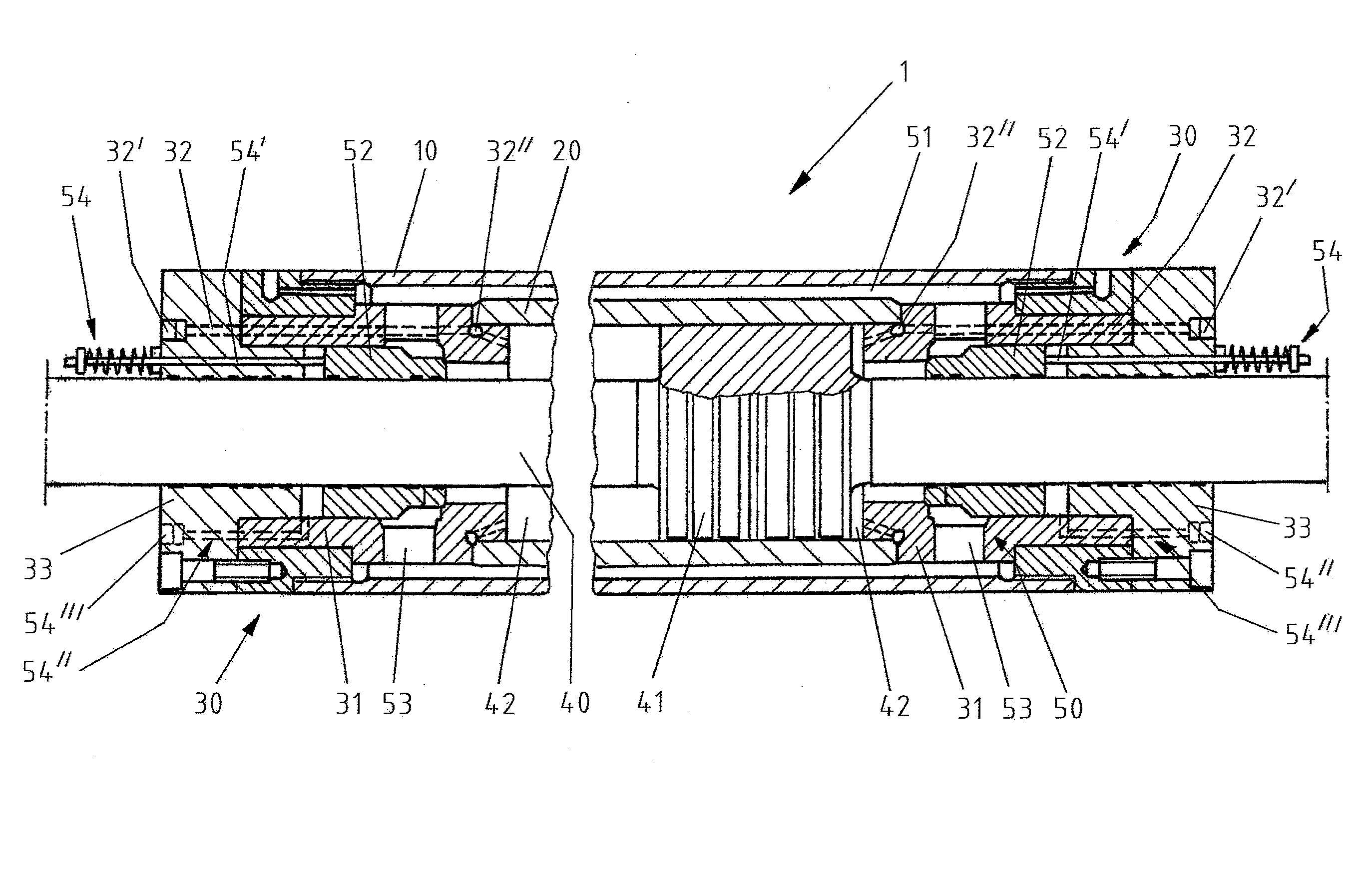
도 1에는, 동기 실린더(1)가 도시되어 있다. 더 구체적으로 말하면, 본 실시예에서 실질적으로 반사 대칭으로 구성되어 있는 실린더(1)의 두 단부 섹션이 종단면도로 도시되어 있다.In Fig. 1, a synchronizing
유압 실린더(1)는 중공 외부 실린더(10)와, 중공 내부 실린더(20)와, 좌측 및 우측의 각각 하나의 헤드 섹션(30)과, 자신에 통합되거나 자신과 연결된 작동 피스톤(41)을 구비한 피스톤 로드(40)를 포함한다. 헤드 섹션(30)은 실린더 헤드 캐리어(31)와 실린더 폐쇄부(33)를 포함하며, 그럼으로써 유압 실린더(1)는 두 단부에서 폐쇄되고 내부 실린더(20)는 외부 실린더(10)에 상대적으로 고정된다. 내부 실린더(20)는 외부 실린더(10) 내에 수용되고, 두 실린더는 서로 동심으로 위치하며, 그럼으로써 하기에서 상세하게 기재되는 바이패스 또는 우회 장치(50)의 구성요소인 환형 간극(51)이 내부 실린더(20)와 외부 실린더(10) 사이에 형성된다. 작동 피스톤(41)은 내부 실린더(20) 내에서 변위 가능하게 장착된다. 피스톤 로드(40)는 작동 피스톤(41)의 양측에서 연장되어 각각의 헤드 섹션(30)들을 관통하며, 그리고 헤드 섹션들을 통해 안내된다. 별도로 기재되지는 않지만, 그러나 도 1에는 부분적으로 도시되어 있으면서 유압 실린더(1)의 완벽한 작동을 보장하는 것이면서 피스톤 로드(40) 및 작동 피스톤(41)을 지지하기 위한 실링들 및 부재들은 적합한 위치들에 제공될 수 있다.The
작동 피스톤(41)의 좌측 및 우측에는 압력 챔버(42)들이 위치되며, 이 압력 챔버들은 작동 피스톤(41), 내부 실린더(20), 그리고 예컨대 실린더 헤드 캐리어(31) 및 하기에 기재되는 바이패스 밸브(52)와 같은 헤드 측 구성요소들에 의해 에워싸이고 이들에 의해 범위 한정된다. 작동 피스톤(41)은 양측에서부터 압력 챔버(42)들 내에 위치되는 압력 매체 또는 유압 유체(예: 유압 오일)에 의해 가압된다. 유압 유체는 본원에서는 유압 유체 라인(32)들로서 지칭되는 보어들 또는 라인들을 경유하여 압력 챔버(42)들 내로 공급된다. 유압 유체 라인(32)들은 두 헤드 섹션(30)을 통과하여 연장된다. 유압 유체 라인(32)들은 유압 유체 포트(32'), 유압 유체 환형 라인(32"), 그리고 가압된 유압 유체를 압력 챔버(42)들로 확실하게 공급하고 분배하며 배출하기에 적합한 다른 구성요소들을 포함할 수 있거나, 또는 이들과 유체공학적으로 연결될 수 있다.
두 압력 챔버(42) 사이의 유압 유체의 압력차는, 축 방향으로 작동 피스톤(41) 및 그에 따른 피스톤 로드(40)의 변위를 야기할 수 있는, 작동 피스톤(41)에 작용하는 힘을 야기한다. 이를 위해, 해당하는 유압 유체 라인(32)을 통해 두 압력 챔버(42) 중 일측 내로 유압 유체의 유입이 실행되고 타측 압력 챔버(42)에서는 유압 유체의 변위가 실행되며, 유압 유체는 타측 유압 유체 라인(32)을 경유하여 배출된다. 양측에서 작동 피스톤(41)의 가압 표면의 크기가 동일하게 됨으로써, 유압 실린더(1)는 동기식 실린더(synchronous cylinder)로서도 지칭되는 동기 실린더로서 작용한다. 이런 작동 모드는, 작동 피스톤(41)의 무압력식 또는 저압력식 변위(pressureless or low-pressure displacement)를 가능하게 하는 하기에서 기재되는 견인 작동 모드와의 구분을 위해 작업 모드로서 지칭된다.The differential pressure of the hydraulic fluid between the two
작동 피스톤(41)의 신속한 무압력식 이동을 위해(예컨대 압출 설비 내에서 수용 장치를 설정하거나 조정하기 위해), 유압 실린더(1)는 바이패스 장치(50)를 포함한다. 바이패스 장치는 본 실시예에서 환형 간극(51), 2개의 바이패스 밸브(52), 환형 간극(51)과 유체로 연결되어 있는 바이패스 라인(53)들, 및 작동 장치(54)들을 포함한다. 두 바이패스 밸브(52)는, 피스톤 로드(40) 상에서, 두 헤드 섹션(30)의 영역에서 안내되며, 그리고 작동 장치(54)에 의해 축 방향으로 작동됨으로써, 다시 말해 변위됨으로써, 바이패스 라인(53)들을 개방하고 폐쇄한다. 바이패스 밸브(52)가 개방된 경우, 유압 유체는 해당 유압 챔버(42)로부터 가까이에 배치된 바이패스 라인(53) 내로 유입되며, 그리고 유압 유체는 상기 바이패스 라인으로부터 환형 간극(51) 내에 도달한다. 두 바이패스 밸브(52)가 개방된다면, 작동 피스톤(41)은 상기 방식으로 힘이 없거나 힘이 적은 상태에서 변위되는데, 그 이유는 바이패스 라인(53)들 및 환형 간극(51)을 통해 두 압력 챔버(42) 간의 유체 연결부가 존재하기 때문이다. 이 경우, 환형 간극(51)은 자신의 외부 배치 및 환형 형상을 통해 유체공학적으로 특히 최적인 거동을 가능하게 한다.The
바이패스 밸브(52)들의 작동은 작동 장치(54)들을 통해 수행된다. 상기 작동 장치들은, 본 실시예에서, 해당 헤드 섹션(30)들을 통과하여 연장되고 바이패스 밸브(52)와 연결되어 스프링에 의해 예압된 작동 로드(54')와, 작동 포트(54"'), 보어 및 챔버(도면부호 없음)를 구비한 작동 유압 섹션(54")을 포함한다. 바이패스 밸브(54)가 여기서는 예컨대 스프링에 의해 예압됨으로써, 바이패스 밸브(52)는 자동으로 우선 위치(preference position)로 이동된다. 또한, 작동 포트(54"')를 경유하여 유체가 작동 유압 섹션(54") 내로 유입되거나 배출됨으로써, 작동 밸브(52)가 작동된다.The operation of the
작동 피스톤(41)을 무압력 또는 저압력 상태에서 이송하기 위한 바이패스 장치(50)는 상기에 기재한 환형 간극(51)에 의해 실현되며, 이 환형 간극은 동심 중공 실린더(10 및 20)들에 의해 바깥쪽에서 작동 피스톤(41)을 둘러싸면서 형성되어 있다. 이런 기술적 해결책은 공간을 절약하며, 그리고 유동 조건과 관련하여 탁월한데, 그 이유는 환형 간극(51)이 다른 해결책들과 비교하여 최소의 유동 손실을 나타내기 때문이다. 본원에서 예시로서 설명되고 피스톤 로드(40) 상에서 안내되며 그 피스톤 로드에 대해 동심으로 제공되는 환형 바이패스 밸브(52)들은 유압 실린더(1)의 작동 모드들의 신속하면서도 확실한 전환을 허용한다. 이처럼, 두 압력 챔버(42) 간, 또는 환형 간극(51)에서 압력 챔버(42)들 내로 유압 유체의 과류(overflow)의 목표하는 제어는 기술적으로 간단하고 고장에 민감하지 않으면서 장기 내구성이 있는 방식으로 실현된다. 또한, 본원에서 설명되는 기술적 해결책은 적은 개수의 유압 포트들을 포함하며, 그럼으로써 유압 실린더(1)의 작동은 추가로 간소화된다.The
도 2에는, 작동 장치(54)와 관련하여 변형된 구성이 도시되어 있다. 도해의 목적을 위해, 동기 실린더(1)를 절단한 종단면도 중 오직 일부분만이 도시되어 있지만, 그러나 상기 동기 실린더는 (도 1에서처럼) 실질적으로 반사 대칭으로 구성될 수 있다.In Fig. 2, a modified configuration is shown in relation to the
도 1의 동기 실린더와 달리, 바이패스 밸브(52)들의 작동을 위한 작동 장치(54)는 바깥쪽에 위치하는 리턴 스프링을 구비한 작동 로드(54')를 포함하는 것이 아니라, 바이패스 밸브(52)의 복귀 또는 예압은 안쪽에 위치하는 스프링(55)을 통해 수행된다. 작동 포트(54"')를 구비한 작동 유압 섹션(54")은 실질적으로 변함이 없다. 작동 포트(54"')에 대향하는 작동 유압 섹션(54")의 단부 상에는 (도면부호는 없지만, 도 2에 잘 확인될 수 있는) 환형 챔버가 제공되며, 이 환형 챔버는 바이패스 밸브(52)의 일측에 인접한다. 바이패스 밸브(52)의 작동은 도 1의 실시예에서처럼 수행되며, 다시 말하면 바이패스 밸브(52)가 여기서는 도 2에 따라서 안쪽에 위치하는 스프링(55)에 의해 예압됨으로써, 바이패스 밸브(52)는 자동으로 우선 위치로 이동된다. 작동 포트(54"')를 경유하여 유체가 작동 유압 섹션(54") 내로 유입되거나 배출됨으로써, 작동 밸브(52)가 작동된다.Unlike the synchronous cylinder of FIG. 1, the
동기 실린더(1)는, 가늘고 긴 설계를 통해, 압출 설비의 실린더 바(cylinder bar)를 통해 안내될 수 있다. 이런 이유에서, 유압 실린더(1)는 특히 바람직하게는 압출 설비들의 분야에서, 특히 힘 기능(force function)을 포함하여 수용 장치 운동학(kinematics)의 실현을 위해 이용될 수 있다. 본원의 동기 실린더는, 전체 행정에 걸친 무압력식 조정을 통해 견인 모드에서 작업 모드로 전환될 수 있다는 큰 장점을 갖는다. 그에 따라, 동기 실린더(1)는, 모든 위치에서, 온전한 실린더 힘으로 완전한 행정에 걸친 신속 이송을 위해 경우에 따라 제공된 전기 모터들을 보조할 수 있다.The synchronizing
압출 설비(100) 내에서 동기 실린더(1)의 장착 위치는 도 3에 도시되어 있다. 자신의 구성이 도 1과 도 2에서보다 도 3에서는 좀 더 덜 상세하게 도시되어 있는 동기 실린더(1)는 실린더 바(101)에 의해 안내된다. 피스톤 로드(40)의 일측은 수용 장치(102)와 연결되며, 이 수용 장치는 동기 실린더(1)를 통해 예컨대 블록 교체를 위한 위치와 전방 단부 위치, 즉 압착, 환기 및 박리가 수행되는 작업 위치 사이에서 이송될 수 있다. 그 대안으로, 수용 장치(102)는, 블록 교체 위치와 작업 위치 사이에서 수용 장치(102)를 이동시키는 미도시한 하나 또는 복수의 전기 모터를 통해 이송된다. 이 경우, 동기 실린더(1)는 외부에서 이동된다. 상기 외부 이동을 위해, 다시 말하면 동기 실린더(1)의 신속한 무압력식 작동을 위해, 상기 동기 실린더는 상기에 기재한 방식으로 견인 작동 모드로 전환된다.The mounting position of the synchronizing
도 4에는, 도 1 내지 도 3에 따른 제1 실시형태에서와 달리 바이패스 장치(50)가 바이패스 라인(103)의 형태로 하우징의 외부에 배치되어 각각의 바이패스 밸브(52)들을 통해 압력 챔버(42)들을 서로 연결하는 것인 본 발명에 따른 동기 실린더(1)의 대안의 실시형태가 도시되어 있다. 바이패스 라인(103)은 도 1 내지 도 3의 실시형태들에 따른 외부 실린더(10)와 내부 실린더(20) 간의 환형 간극을 대체한다. 그러나 바이패스 라인(103)은 도 1 내지 도 3의 실시형태들에 따른 환형 간극(51)과 동일한 기술적 효과들을 실현한다.4, the
도 5에는, 본 발명에 따른 동기 실린더(1)의 또 다른 실시형태가 측면도로, 그리고 도 5의 절단선 AA를 따라 절단된 단부면의 도면으로 도시되어 있다. 도 5b에 따른 단부면의 도면에서는, 동기 실린더(1)의 하우징의 내부에서 외부 실린더(10)의 외부에 4개의 바이패스 라인(103a~d)이 배치되어 있음이 확인된다. 상기 바이패스 라인(103a~d)들은 도 4에 따른 바이패스 라인(103)과 동일하게 도 1 내지 도 3의 실시형태들에 따른 환형 간극(51)을 전체적으로 대체한다. 바이패스 라인(103a~d)들은 도 4에 따른 바이패스 라인(103)과 동일하게 동기 실린더(1)의 압력 챔버(42)들을 서로 연결한다.5, another embodiment of the synchronizing
적용될 수 있는 점에 한해, 실시예들에서 설명되는 모든 개별 특징은, 본 발명의 범위에서 벗어나지 않으면서, 서로 조합될 수 있고, 그리고/또는 서로 교환될 수 있다. 예시적인 실시형태들의 범위에서 설명되는 기술적 특징들 모두가 본 발명에 대해 필수적인 것일 필요는 없다. 이런 식으로, 예컨대 환형 간극(51)과 압력 챔버(42)들 사이의 유입 및 유출은 본원에서 설명한 바이패스 라인(53)들에 의한 것과 다르게 실현될 수 있다. 바이패스 밸브(52)들 역시도, 비록 명시한 기술적 해결책이 선호되기는 하지만, 다르게 구성되고, 그리고/또는 포지셔닝될 수도 있다.All the individual features described in the embodiments may be combined with one another and / or exchanged with one another, without departing from the scope of the present invention, as long as they can be applied. It is not necessary that all of the technical features described in the scope of the exemplary embodiments are necessary for the present invention. In this way, for example, the inflow and outflow between the
1: 동기 실린더
10: 외부 실린더
20: 내부 실린더
30: 헤드 섹션
31: 실린더 헤드 캐리어
32: 유압 유체 라인
32': 유압 유체 포트
32": 유압 유체 환형 라인
33: 실린더 폐쇄부
40: 피스톤 로드
41: 작동 피스톤
42: 압력 챔버
50: 바이패스 장치
51: 환형 간극
52: 바이패스 밸브
53: 바이패스 라인
54: 작동 장치
54': 작동 로드
54": 작동 유압 섹션
54"': 작동 포트
55: 바이패스 밸브의 예압용 스프링
100: 압출 설비
101: 실린더 바
102: 수용 장치
103: 바이패스 라인1: synchronous cylinder
10: External cylinder
20: inner cylinder
30: head section
31: Cylinder head carrier
32: Hydraulic fluid line
32 ': Hydraulic fluid port
32 ": Hydraulic fluid annular line
33: cylinder closing portion
40: Piston rod
41: Working piston
42: Pressure chamber
50: Bypass device
51: annular clearance
52: Bypass valve
53: Bypass line
54: Operation device
54 ': operating rod
54 ": Working hydraulic section
54 "': Operation port
55: Spring for pre-pressure of bypass valve
100: Extrusion equipment
101: Cylinder bar
102: receiving device
103: Bypass line
Claims (12)
Applications Claiming Priority (5)
| Application Number | Priority Date | Filing Date | Title |
|---|---|---|---|
| DE102016202357 | 2016-02-16 | ||
| DE102016202357.8 | 2016-02-16 | ||
| DE102016214767.6A DE102016214767A1 (en) | 2016-02-16 | 2016-08-09 | Synchronous cylinder for extrusion presses |
| DE102016214767.6 | 2016-08-09 | ||
| PCT/EP2017/052135 WO2017140499A1 (en) | 2016-02-16 | 2017-02-01 | Synchronizing cylinder for extrusion plants |
Publications (2)
| Publication Number | Publication Date |
|---|---|
| KR20180098346A true KR20180098346A (en) | 2018-09-03 |
| KR102166035B1 KR102166035B1 (en) | 2020-10-15 |
Family
ID=59410422
Family Applications (1)
| Application Number | Title | Priority Date | Filing Date |
|---|---|---|---|
| KR1020187021301A Active KR102166035B1 (en) | 2016-02-16 | 2017-02-01 | Synchronous cylinder for extrusion equipment |
Country Status (9)
| Country | Link |
|---|---|
| US (1) | US10670052B2 (en) |
| EP (1) | EP3417178B1 (en) |
| JP (1) | JP6851388B2 (en) |
| KR (1) | KR102166035B1 (en) |
| CN (1) | CN108603521B (en) |
| DE (1) | DE102016214767A1 (en) |
| ES (1) | ES2880351T3 (en) |
| TW (1) | TW201738010A (en) |
| WO (1) | WO2017140499A1 (en) |
Cited By (1)
| Publication number | Priority date | Publication date | Assignee | Title |
|---|---|---|---|---|
| KR20240003312A (en) * | 2022-06-30 | 2024-01-08 | 주식회사 5G엔지니어링 | Extrusion molding system with improved heating efficiency for seamless pipe manufactured |
Families Citing this family (4)
| Publication number | Priority date | Publication date | Assignee | Title |
|---|---|---|---|---|
| DE102019007754A1 (en) * | 2019-11-08 | 2021-05-12 | Bümach Engineering International B.V. | Working cylinder and process for its manufacture |
| CN113389767B (en) * | 2021-07-23 | 2024-06-21 | 中国科学院合肥物质科学研究院 | Double-acting pneumatic actuator with long-stroke and large-cylinder-diameter structure and control system thereof |
| US11867072B2 (en) * | 2021-12-06 | 2024-01-09 | Woodward, Inc. | On-line verifiable trip and throttle valve actuator |
| EP4445031A1 (en) * | 2021-12-06 | 2024-10-16 | Woodward, Inc. | Fluid actuator |
Citations (3)
| Publication number | Priority date | Publication date | Assignee | Title |
|---|---|---|---|---|
| JPS5416078A (en) * | 1977-07-06 | 1979-02-06 | Nomura Yoshihisa | Two stages speed changable plural motion cylinder |
| JPS63141898A (en) * | 1986-11-20 | 1988-06-14 | サンドストランド・コーポレーション | Non-jamming actuator device |
| US6058826A (en) * | 1998-06-08 | 2000-05-09 | Dietrich; Otto E. | Power steering cylinder assembly |
Family Cites Families (17)
| Publication number | Priority date | Publication date | Assignee | Title |
|---|---|---|---|---|
| DE920709C (en) | 1950-05-03 | 1954-11-29 | Eduard Neumann | Hydraulic shock absorber for road or rail vehicles |
| JPS5872509U (en) * | 1981-11-11 | 1983-05-17 | オカダ鑿岩機株式会社 | Hydraulic cylinder damage prevention device |
| DE3801684A1 (en) * | 1988-01-21 | 1989-07-27 | Huperz Adalbert | Hydraulic cylinder with a dimensionally stable piston guide |
| DE3836702C1 (en) | 1988-10-28 | 1989-09-14 | Hasenclever Maschf Sms | Extrusion press for indirect extrusion of metal |
| DE19511522C1 (en) * | 1995-03-29 | 1996-07-18 | Fluidtech Gmbh | Switching mechanism for hydraulic actuator |
| US5727444A (en) * | 1996-02-20 | 1998-03-17 | Dietrich; Otto E. | Power steering cylinder assembly |
| DE19925600A1 (en) | 1999-06-04 | 2000-12-14 | Sbs Sondermaschinen Gmbh | Light construction hydraulic cylinder has tie rod mounted in outer cylinder tube that bears peripheral forces of hydraulic internal pressure, either outside or inside working chamber |
| CN2603871Y (en) * | 2003-02-04 | 2004-02-18 | 张书奇 | Hydraulic automatic reciprocating hydrocylinder |
| US8015913B2 (en) * | 2004-03-10 | 2011-09-13 | Sunstream Scientific, Inc. | Pneumatic cylinder for precision servo type applications |
| WO2006129746A1 (en) * | 2005-06-02 | 2006-12-07 | Amada Company, Limited | Ram position detection method, ram drive method, ram drive device, and press machine having the ram drive device |
| JP5401678B2 (en) | 2009-02-09 | 2014-01-29 | 株式会社イデアルスター | Dialysis patient probe gauze and dialysis patient judgment device |
| DE102010034610A1 (en) * | 2010-08-18 | 2012-02-23 | Robert Bosch Gmbh | Hydraulic linear drive |
| CN202510454U (en) * | 2012-01-11 | 2012-10-31 | 河北凯恩机电设备有限公司 | Combined hydraulic cylinder with double-acting section |
| DE102012009182A1 (en) * | 2012-05-10 | 2013-11-14 | Sms Meer Gmbh | Hydraulic extruder and method for operating a hydraulic extruder |
| DE102012012142A1 (en) * | 2012-06-20 | 2013-12-24 | Robert Bosch Gmbh | Hydraulic actuating device |
| WO2016171594A1 (en) * | 2015-04-21 | 2016-10-27 | Saab Ab | A fluid actuator arrangement |
| CN105221514B (en) * | 2015-09-29 | 2017-03-29 | 中国船舶重工集团公司第七一九研究所 | A kind of integrated hydraulic cylinder with bidirection press safeguard protection |
-
2016
- 2016-08-09 DE DE102016214767.6A patent/DE102016214767A1/en not_active Withdrawn
-
2017
- 2017-02-01 KR KR1020187021301A patent/KR102166035B1/en active Active
- 2017-02-01 CN CN201780010751.3A patent/CN108603521B/en not_active Expired - Fee Related
- 2017-02-01 JP JP2018543196A patent/JP6851388B2/en active Active
- 2017-02-01 EP EP17702621.8A patent/EP3417178B1/en active Active
- 2017-02-01 US US16/066,701 patent/US10670052B2/en active Active
- 2017-02-01 ES ES17702621T patent/ES2880351T3/en active Active
- 2017-02-01 WO PCT/EP2017/052135 patent/WO2017140499A1/en not_active Ceased
- 2017-02-07 TW TW106103952A patent/TW201738010A/en unknown
Patent Citations (3)
| Publication number | Priority date | Publication date | Assignee | Title |
|---|---|---|---|---|
| JPS5416078A (en) * | 1977-07-06 | 1979-02-06 | Nomura Yoshihisa | Two stages speed changable plural motion cylinder |
| JPS63141898A (en) * | 1986-11-20 | 1988-06-14 | サンドストランド・コーポレーション | Non-jamming actuator device |
| US6058826A (en) * | 1998-06-08 | 2000-05-09 | Dietrich; Otto E. | Power steering cylinder assembly |
Cited By (1)
| Publication number | Priority date | Publication date | Assignee | Title |
|---|---|---|---|---|
| KR20240003312A (en) * | 2022-06-30 | 2024-01-08 | 주식회사 5G엔지니어링 | Extrusion molding system with improved heating efficiency for seamless pipe manufactured |
Also Published As
| Publication number | Publication date |
|---|---|
| CN108603521B (en) | 2021-06-04 |
| EP3417178A1 (en) | 2018-12-26 |
| US10670052B2 (en) | 2020-06-02 |
| EP3417178B1 (en) | 2021-04-14 |
| KR102166035B1 (en) | 2020-10-15 |
| DE102016214767A1 (en) | 2017-08-17 |
| TW201738010A (en) | 2017-11-01 |
| US20190017522A1 (en) | 2019-01-17 |
| JP6851388B2 (en) | 2021-03-31 |
| JP2019511681A (en) | 2019-04-25 |
| ES2880351T3 (en) | 2021-11-24 |
| CN108603521A (en) | 2018-09-28 |
| WO2017140499A1 (en) | 2017-08-24 |
Similar Documents
| Publication | Publication Date | Title |
|---|---|---|
| KR20180098346A (en) | Synchronous cylinder for extrusion equipment | |
| RU2708753C2 (en) | Integrated multi-valve header | |
| US5103866A (en) | Poppet valve and valve assemblies utilizing same | |
| JP6867394B2 (en) | Valves, especially 4/2 direction slide valves | |
| US8596575B2 (en) | Aircraft actuator | |
| CN102639880B (en) | Valve arrangement | |
| EP0803651B1 (en) | Fluid-controlled actuator assembly | |
| ITBS20100177A1 (en) | PNEUMATIC GRIPPING GRIPPER | |
| KR20140142680A (en) | A Directional Valve and Method of Operation | |
| EP2670987B1 (en) | Directional valve equipped with pressure control | |
| CN108150475A (en) | Load sensing multi-way valve group and with its walking machine hydraulic system | |
| KR101717042B1 (en) | An valve actuator using air compression | |
| US20100186583A1 (en) | Hollow double rod cylinder actuator | |
| EP3885585B1 (en) | Cylinder drive device | |
| US11971119B2 (en) | Pinch valve assembly | |
| US4969387A (en) | Hydraulic drive unit with single piston rod and plural cylinder bodies | |
| EP2497958A2 (en) | Fluid operated actuation system | |
| CN211117765U (en) | Electromagnetic valve and mechanical equipment | |
| US20100206413A1 (en) | Hydraulic valve device | |
| US20250137473A1 (en) | Working cylinder with pressure medium overflow | |
| EP1070854A2 (en) | Multiway valve | |
| KR100534735B1 (en) | Oil Pressure Cylinder | |
| RU2347717C1 (en) | Redundant electrohydraulic drive | |
| JP2011075014A (en) | Hydraulic cylinder | |
| RO128106B1 (en) | Proportional pneumatic distributor with piezoelectric actuator |
Legal Events
| Date | Code | Title | Description |
|---|---|---|---|
| A201 | Request for examination | ||
| PA0105 | International application |
Patent event date: 20180724 Patent event code: PA01051R01D Comment text: International Patent Application |
|
| PA0201 | Request for examination | ||
| PG1501 | Laying open of application | ||
| E902 | Notification of reason for refusal | ||
| PE0902 | Notice of grounds for rejection |
Comment text: Notification of reason for refusal Patent event date: 20191010 Patent event code: PE09021S01D |
|
| AMND | Amendment | ||
| E601 | Decision to refuse application | ||
| PE0601 | Decision on rejection of patent |
Patent event date: 20200407 Comment text: Decision to Refuse Application Patent event code: PE06012S01D Patent event date: 20191010 Comment text: Notification of reason for refusal Patent event code: PE06011S01I |
|
| X091 | Application refused [patent] | ||
| AMND | Amendment | ||
| PX0901 | Re-examination |
Patent event code: PX09011S01I Patent event date: 20200407 Comment text: Decision to Refuse Application Patent event code: PX09012R01I Patent event date: 20191209 Comment text: Amendment to Specification, etc. |
|
| PX0701 | Decision of registration after re-examination |
Patent event date: 20200710 Comment text: Decision to Grant Registration Patent event code: PX07013S01D Patent event date: 20200703 Comment text: Amendment to Specification, etc. Patent event code: PX07012R01I Patent event date: 20200407 Comment text: Decision to Refuse Application Patent event code: PX07011S01I Patent event date: 20191209 Comment text: Amendment to Specification, etc. Patent event code: PX07012R01I |
|
| X701 | Decision to grant (after re-examination) | ||
| GRNT | Written decision to grant | ||
| PR0701 | Registration of establishment |
Comment text: Registration of Establishment Patent event date: 20201008 Patent event code: PR07011E01D |
|
| PR1002 | Payment of registration fee |
Payment date: 20201012 End annual number: 3 Start annual number: 1 |
|
| PG1601 | Publication of registration | ||
| PR1001 | Payment of annual fee |
Payment date: 20231004 Start annual number: 4 End annual number: 4 |
|
| PR1001 | Payment of annual fee |
Payment date: 20240927 Start annual number: 5 End annual number: 5 |