KR20180098335A - Lossless band division and band combining using global pass filters - Google Patents
Lossless band division and band combining using global pass filters Download PDFInfo
- Publication number
- KR20180098335A KR20180098335A KR1020187021177A KR20187021177A KR20180098335A KR 20180098335 A KR20180098335 A KR 20180098335A KR 1020187021177 A KR1020187021177 A KR 1020187021177A KR 20187021177 A KR20187021177 A KR 20187021177A KR 20180098335 A KR20180098335 A KR 20180098335A
- Authority
- KR
- South Korea
- Prior art keywords
- output
- band
- input
- samples
- stream
- Prior art date
- Legal status (The legal status is an assumption and is not a legal conclusion. Google has not performed a legal analysis and makes no representation as to the accuracy of the status listed.)
- Granted
Links
Images


Classifications
-
- G—PHYSICS
- G10—MUSICAL INSTRUMENTS; ACOUSTICS
- G10L—SPEECH ANALYSIS TECHNIQUES OR SPEECH SYNTHESIS; SPEECH RECOGNITION; SPEECH OR VOICE PROCESSING TECHNIQUES; SPEECH OR AUDIO CODING OR DECODING
- G10L19/00—Speech or audio signals analysis-synthesis techniques for redundancy reduction, e.g. in vocoders; Coding or decoding of speech or audio signals, using source filter models or psychoacoustic analysis
- G10L19/0017—Lossless audio signal coding; Perfect reconstruction of coded audio signal by transmission of coding error
-
- G—PHYSICS
- G10—MUSICAL INSTRUMENTS; ACOUSTICS
- G10L—SPEECH ANALYSIS TECHNIQUES OR SPEECH SYNTHESIS; SPEECH RECOGNITION; SPEECH OR VOICE PROCESSING TECHNIQUES; SPEECH OR AUDIO CODING OR DECODING
- G10L19/00—Speech or audio signals analysis-synthesis techniques for redundancy reduction, e.g. in vocoders; Coding or decoding of speech or audio signals, using source filter models or psychoacoustic analysis
- G10L19/008—Multichannel audio signal coding or decoding using interchannel correlation to reduce redundancy, e.g. joint-stereo, intensity-coding or matrixing
-
- G—PHYSICS
- G10—MUSICAL INSTRUMENTS; ACOUSTICS
- G10L—SPEECH ANALYSIS TECHNIQUES OR SPEECH SYNTHESIS; SPEECH RECOGNITION; SPEECH OR VOICE PROCESSING TECHNIQUES; SPEECH OR AUDIO CODING OR DECODING
- G10L19/00—Speech or audio signals analysis-synthesis techniques for redundancy reduction, e.g. in vocoders; Coding or decoding of speech or audio signals, using source filter models or psychoacoustic analysis
- G10L19/02—Speech or audio signals analysis-synthesis techniques for redundancy reduction, e.g. in vocoders; Coding or decoding of speech or audio signals, using source filter models or psychoacoustic analysis using spectral analysis, e.g. transform vocoders or subband vocoders
- G10L19/0204—Speech or audio signals analysis-synthesis techniques for redundancy reduction, e.g. in vocoders; Coding or decoding of speech or audio signals, using source filter models or psychoacoustic analysis using spectral analysis, e.g. transform vocoders or subband vocoders using subband decomposition
-
- G—PHYSICS
- G10—MUSICAL INSTRUMENTS; ACOUSTICS
- G10L—SPEECH ANALYSIS TECHNIQUES OR SPEECH SYNTHESIS; SPEECH RECOGNITION; SPEECH OR VOICE PROCESSING TECHNIQUES; SPEECH OR AUDIO CODING OR DECODING
- G10L19/00—Speech or audio signals analysis-synthesis techniques for redundancy reduction, e.g. in vocoders; Coding or decoding of speech or audio signals, using source filter models or psychoacoustic analysis
- G10L19/02—Speech or audio signals analysis-synthesis techniques for redundancy reduction, e.g. in vocoders; Coding or decoding of speech or audio signals, using source filter models or psychoacoustic analysis using spectral analysis, e.g. transform vocoders or subband vocoders
- G10L19/032—Quantisation or dequantisation of spectral components
- G10L19/038—Vector quantisation, e.g. TwinVQ audio
-
- G—PHYSICS
- G10—MUSICAL INSTRUMENTS; ACOUSTICS
- G10L—SPEECH ANALYSIS TECHNIQUES OR SPEECH SYNTHESIS; SPEECH RECOGNITION; SPEECH OR VOICE PROCESSING TECHNIQUES; SPEECH OR AUDIO CODING OR DECODING
- G10L19/00—Speech or audio signals analysis-synthesis techniques for redundancy reduction, e.g. in vocoders; Coding or decoding of speech or audio signals, using source filter models or psychoacoustic analysis
- G10L19/04—Speech or audio signals analysis-synthesis techniques for redundancy reduction, e.g. in vocoders; Coding or decoding of speech or audio signals, using source filter models or psychoacoustic analysis using predictive techniques
- G10L19/16—Vocoder architecture
- G10L19/18—Vocoders using multiple modes
- G10L19/24—Variable rate codecs, e.g. for generating different qualities using a scalable representation such as hierarchical encoding or layered encoding
-
- G—PHYSICS
- G10—MUSICAL INSTRUMENTS; ACOUSTICS
- G10L—SPEECH ANALYSIS TECHNIQUES OR SPEECH SYNTHESIS; SPEECH RECOGNITION; SPEECH OR VOICE PROCESSING TECHNIQUES; SPEECH OR AUDIO CODING OR DECODING
- G10L19/00—Speech or audio signals analysis-synthesis techniques for redundancy reduction, e.g. in vocoders; Coding or decoding of speech or audio signals, using source filter models or psychoacoustic analysis
- G10L19/04—Speech or audio signals analysis-synthesis techniques for redundancy reduction, e.g. in vocoders; Coding or decoding of speech or audio signals, using source filter models or psychoacoustic analysis using predictive techniques
- G10L19/26—Pre-filtering or post-filtering
Landscapes
- Engineering & Computer Science (AREA)
- Physics & Mathematics (AREA)
- Audiology, Speech & Language Pathology (AREA)
- Computational Linguistics (AREA)
- Signal Processing (AREA)
- Health & Medical Sciences (AREA)
- Human Computer Interaction (AREA)
- Acoustics & Sound (AREA)
- Multimedia (AREA)
- Spectroscopy & Molecular Physics (AREA)
- Quality & Reliability (AREA)
- Mathematical Physics (AREA)
- Compression, Expansion, Code Conversion, And Decoders (AREA)
- Complex Calculations (AREA)
- Networks Using Active Elements (AREA)
Abstract
전역통과 필터링을 이용한 신호 샘플들의 스트림들의 무손실 대역분할 및 대역결합을 위한 방법들 및 장치들이 설명된다. 상기 대역분할 작동은 오리지널 스트림을 상기 오리지널 스트림의 짝수 및 홀수 샘플들을 나타내는 2개의 중간 스트림들로 리포맷하고, 이후 상기 오리지널 스트림의 고주파 요소들 및 저주파 요소들을 나타내는 2개의 출력 서브스트림을 제공하도록 매트릭스가 이들을 필터링한다. 반대로, 대역결합 작동 매트릭스는 2개의 양자화된 중간 서브스트림들을 제공하기 위해 2개의 부대역 스트림들을 필터링하고, 이후 출력 스트림을 제공하기 위해 필터링된 스트림들을 인터리브하여, 중간 서브스트림들이 출력 스트림의 짝수 및 홀수 샘플들이 되도록 한다. Methods and apparatus for lossless band division and band combining of streams of signal samples using global pass filtering are described. The band division operation reformatting the original stream into two intermediate streams representing the even and odd samples of the original stream and then providing the two output substreams representing the high frequency components and low frequency components of the original stream, Lt; / RTI > filters them. Conversely, the band combining actuation matrix filters the two subband streams to provide two quantized intermediate sub-streams, and then interleaves the filtered streams to provide an output stream so that the intermediate sub-streams are even and non- Let it be an odd number of samples.

Description
본 발명은 샘플 신호들의 처리에 관한 것으로, 보다 상세하게는 이러한 신호들의 무손실 대역분할 및 대역결합(bandjoining)에 관한 것이다. The present invention relates to the processing of sample signals, and more particularly to lossless band division and band joining of such signals.
많은 어플리케이션은 낮은 샘플링 레이트에서 개별적으로 처리되거나 전송될 수 있는 부대역(subband) 신호들을 생성하기 위해 샘플 신호가 2개 이상의 주파수 대역들로 분할될 것을 요구하며, 최대 샘플링 레이트에서 신호를 생성하기 위한 재결합이 이어진다. 분할 및 결합을 수행하기 위한 (구적 거울 필터(Quadrature Mirror Filters)를 포함하는) 다위상 필터링 네트워크는 광범위한 연구의 주제로 되어 왔다. 대역분할 방법에 의해 잠재적으로 도입되는 신호 가공물들은 통과대역 리플 및 앨리어싱을 포함하지만, 리플이 제로이고, 부대역 신호들이 최종 대역결합 필터로 수정되지 않은 전송 어플리케이션의 경우 부대역 신호들에 존재하는 앨리어스 제품이 최종 재결합에서 취소되는 디자인들이 공지되어 있다.Many applications require that a sample signal be split into two or more frequency bands to produce subband signals that can be individually processed or transmitted at a low sampling rate, Rejoins follow. Multiphase filtering networks (including Quadrature Mirror Filters) for performing splitting and combining have been the subject of extensive research. The signal artifacts that are potentially introduced by the band division method include passband ripple and aliasing but can not be used for transmission applications where the ripple is zero and the subband signals are not modified by the final band combining filter. Designs are known in which the product is canceled in the final recombination.
용어 '무손실'은 상기 통신 문헌에서 이러한 디자인을 언급하기 위해 종종 사용되지만, 그러한 문헌에서 완벽한 산술이 가정되며 그렇게 표시된 디자인은 산술 반올림 에러 존재의 경우 정확한 재구축을 제공하거나 제공하지 않을 수 있다. 이 문서에서 우리는 상기 오디오 문헌의 용어를 채택할 것이며, '무손실'은 이미 양자화된 신호들의 정확한 비트 단위 재구축을 의미한다. 따라서, 무손실 디코더는 인코더에 의해 생성된 임의의 산술적 에러들 또는 양자화들을 반전시켜야 한다. Although the term " lossless " is often used to refer to such a design in the communication literature, complete arithmetic is assumed in such literature and the design so marked may or may not provide accurate reconstruction in the presence of arithmetic rounding errors. In this document we will adopt the terms of the audio document, and 'lossless' means to reconstruct the exact bit-wise of already quantized signals. Thus, a lossless decoder must invert any arithmetic errors or quantizations generated by the encoder.
'리프팅' 기술은 무손실 처리를 실행하는 데 자주 사용되었으며, 리프팅을 이용하는 대역분할/결합 아키텍처들이 A. R. Calderbank, I. Daubechies, W. Sweldens 및 B-L에 의해 설명되었다. Yeo, "정수를 정수에 맵핑하는 파형요소 변환", 특히 그림 4 및 5 참조, Applied and Computational Harmonic Analysis 5, 332-369 (1998). 인코더가 샘플 신호를 저주파(LF)와 고주파 대역(HF)으로 분할하고 이후 대응하는 디코더가 대역을 결합하기 위해, 이러한 아키텍처들은 일반적으로 인코더와 디코더 각각이 두 개의 유한 임펄스 응답(FIR) 필터들을 실행하는 것을 요구한다. 필터들은 불편하게 길어질 수 있으며, 각각은 LF와 HF 대역 간의 전이 폭에 반비례하는 다수의 탭을 필요로한다. 또한, 2-FIR 디자인은 인코더 및 디코더에서 적어도 3개의 FIR 필터들을 각각요구하는 더 큰 대칭성을 달성하기 위해 하프-나이퀴스트(Nyquist) 주파수에 대한 미러-이미지들인 LF와 HF 응답을 제공하지 않는다. The 'lifting' technique is often used to implement lossless processing, and the band division / combination architectures using lifting have been described by A. R. Calderbank, I. Daubechies, W. Sweldens and B-L. Yeo, "Transforming Waveform Elements Mapping Integer to Integer", especially Figures 4 and 5, Applied and Computational Harmonic Analysis 5, 332-369 (1998). In order for the encoder to divide the sample signal into a low frequency (LF) and a high frequency band (HF) and then a corresponding decoder to combine the bands, these architectures typically implement two finite impulse response (FIR) filters . Filters can be uncomfortably long, and each requires a number of taps that are inversely proportional to the transition width between the LF and HF bands. In addition, the 2-FIR design does not provide LF and HF responses, which are mirror-images for the half-Nyquist frequency, to achieve greater symmetry requiring at least three FIR filters at the encoder and decoder, respectively .
통신 문헌에서 대역분할 및 결합의 다른 타입은 IIR 필터링을 이용한다.IIR 필터들은 일반적으로 FIR 필터들보다 주어진 개수의 산술 작동들을 갖는 경사로 달성될 수 있지만, 상기 문헌에서 IIR 대역 분할 및 결합 필터들은 무손실 재구축을 얻지 못한다. 예를 들어, 1996년 9월 10~13일 이탈리아 트리에스테에서 열린 EUSIPCO-96 제8회 유럽 신호 처리 컨퍼런스의 진행에서, Kleinmann T 및 Lacroix A에 의한 "음성 부대역 코딩을 위한 저 지연 IIR QMF 뱅크의 효율적인 디자인"에서, 재구축된 진폭 응답은 평평하지만 크로스오버 주파수 부근에서 그룹 지연이 증가한다. 따라서 이 계획은 양자화 에러들없이 실행된 경우에도 무손실이 아니다. Other types of band segmentation and combination in the communications literature use IIR filtering. Although IR filters can generally be achieved with ramps having a given number of arithmetic operations than FIR filters, IIR band division and combination filters in this document are lossless I do not get a build. For example, in the course of the 8th European Signal Processing Conference at EUSIPCO-96, Trieste, Italy, September 10-13, 1996, a low-delay IIR QMF bank for speech subband coding by Kleinmann T and Lacroix A , The reconstructed amplitude response is flat, but the group delay increases around the crossover frequency. Therefore, this scheme is not lossless even when executed without quantization errors.
따라서, 필요한 것은 무손실 재구축을 제공하는 경제적인 IIR 아키텍처이다. 인코더가 LF 및 HF 대역들을 소비자 제품에 개별적으로 전송하는 어플리케이션들에 대하여, 디코더의 컴퓨터적인 복잡성을 최소화하는 것이 특히 바람직하다.Thus, what is needed is an economical IIR architecture that provides lossless reconstruction. It is particularly desirable to minimize the computational complexity of the decoder for applications in which the encoder individually transmits LF and HF bands to consumer products.
본 발명의 제1 양태는 오리지널 샘플링 레이트를 갖는 양자화된 신호 샘플들의 오리지널 스트림을 상기 오리지널 샘플링 레이트의 절반을 갖는 양자화된 신호 샘플들의 2개의 출력 서브스트림으로 분리하는 방법을 제공하는데, 상기 2개의 출력 서브스트림은 상기 오리지널 스트림의 고주파 요소들 및 저주파 요소들을 각각 나타내며, 상기 방법은:A first aspect of the present invention provides a method of separating an original stream of quantized signal samples having an original sampling rate into two output substreams of quantized signal samples having half the original sampling rate, The sub-stream representing the high-frequency and low-frequency components of the original stream, respectively, the method comprising:
상기 오리지널 스트림을, 상기 오리지널 스트림의 짝수 및 홀수 샘플들을 각각 나타내는 2개의 중간 스트림으로 리포맷하는 단계;Reforming the original stream into two intermediate streams each representing even and odd samples of the original stream;
2개의 출력 서브스트림을 제공하도록 상기 2개의 중간 스트림을 필터링 및 매트릭스화하는 단계를 포함하고,Filtering and matrixing the two intermediate streams to provide two output substreams,
상기 필터링 및 매트릭스화 단계는:Wherein the filtering and matrixing step comprises:
- 샘플들을 갖는 양자화된 신호를 생성하기 위해 양자화기를 이용하는 단계;- using a quantizer to generate a quantized signal having samples;
- 시간 역순으로 양자화된 신호 샘플들을 생성하는 단계; 및- generating quantized signal samples in reverse chronological order; And
- 이미 생성된 양자화된 신호의 샘플들로부터 유도되는 피드백에 따라 양자화된 신호 샘플들을 생성하는 단계를 포함하고, Generating quantized signal samples according to feedback derived from samples of quantized signals already generated,
각각의 출력 서브스트림은 최대 위상 폴들(maximum phase poles)을 포함하는 각각의 전달 함수에 의해 각각의 중간 스트림에 관련된다.Each output substream is associated with a respective intermediate stream by a respective transfer function comprising maximum phase poles.
피드백은 전달 함수에 폴들(poles)을 생성하는데 사용되는데 이는 계수들이 거의 없는 양호한 주파수 식별을 가능하게 한다. 최대 위상 폴들을 만드는 것은 인과적 대역결합기가 위상 왜곡을 제거하는 것을 가능하게 함으로써 Kleinmann 및 Lacroix의 종래기술을 향상시킨다. 샘플들에 대하여 역순으로 작동하는 것은 최대 위상 폴들을 갖는 필터링이 안정적으로 실행되는 것을 가능하게 한다.Feedback is used to generate poles in the transfer function, which allows for good frequency identification with few coefficients. Making the maximum phase poles improves the prior art of Kleinmann and Lacroix by allowing the causal band combiner to eliminate phase distortion. Operating in reverse for the samples enables filtering with maximum phase poles to be performed stably.
바람직하게는, 임의의 출력 서브스트림에 대하여, 양 중간 서브스트림들로부터의 전달 함수는 동일한 DC 이득 크기를 갖는다. 이 방식에서 가감산 매트릭스의 사용은 대역 분할기가 DC를 순수하게 하나의 출력으로 향하게 하고 나이퀴스트 주파수들을 순수하게 다른 하나로 향하게 한다. Preferably, for any output sub-stream, the transfer function from both intermediate sub-streams has the same DC gain size. In this way, the use of an additive matrix allows the band divider to direct the DC to one output purely and direct the Nyquist frequencies to the other one.
몇몇 실시예들에서, 매트릭스 필터링 단계는:In some embodiments, the matrix filtering step comprises:
2개의 중간 스트림들의 샘플들의 오버랩 블록들을 처리하는 단계;Processing overlap blocks of samples of two intermediate streams;
다른 블록과의 오버랩에 대응하는 샘플들의 각각 처리된 블록의 최종 부분을 버리는 단계; 및Discarding a last portion of each processed block of samples corresponding to an overlap with another block; And
샘플들의 각각 처리된 블록의 나머지 부분들을 결합하는 단계를 포함한다.And combining the remaining portions of each processed block of samples.
이 방식으로, 본 발명에 따른 대역분할기는 시간 역전된 블록 상에 국부적으로 작동하는 동안 전체 순방향 순서로 오디오를 처리할 수 있다. 오버랩과 버려짐은 각각의 블록의 처리가 상기 대역분할기 출력들에 영향을 주는 섹션에 도달하기 전에 소산되기 시작할 때 발생하는 트랜션트(transient)를 허용한다.In this way, the band dividers in accordance with the present invention can process audio in an overall forward order while locally operating on time reversed blocks. The overlaps and discards allow a transient that occurs when the processing of each block begins to dissipate before reaching a section that affects the band divider outputs.
바람직하게는, 2개의 출력 서브스트림들은 오리지널 양자화된 스트림이 적절히 초기화된 대역결합기에 의해 정확하게 복원(recover)되도록 하는 것에 요구되는 정보를 함께 포함한다. Preferably, the two output substreams together contain information required to cause the original quantized stream to be correctly recovered by a suitably initialized band combiner.
이 방식으로, 작동이 정확하게 반전될 수 있어 각각의 대역의 무손실 전송, 대역결합을 수반하는 시스템이 전체적으로 무손실로 되는 것을 가능하게 한다. In this manner, the operation can be reversed accurately, making it possible for the system involving lossless transmission, band combining of each band to be totally lossless.
어떠한 2개의 개별 입력 스트림들이 동일한 출력 서브스트림들 및 필터들 내의 잔류 상태 모두를 생성하지 않는 것이 바람직하다. It is desirable that no two separate input streams produce all of the residual states in the same output sub-streams and filters.
이 방식으로, 각각의 가능 출력 세트가 기껏해야 하나의 입력 스트림에 의해 생성되기 때문에, 신호 샘플들에 대한 어떠한 정보도 대역분할기의 작동으로 소실되지 않는다. 결과적으로, 대역분할기는 무손실로 설명될 수 있다. 필터링은 시간에 있어 입력 효과를 퍼트리기 때문에 비교를 포함하는 필터 상태가 필요하다.In this way, since each possible output set is generated by at most one input stream, no information about the signal samples is lost in the operation of the band splitter. As a result, the band splitter can be described as lossless. Filtering requires a filter state that includes a comparison because it spreads the input effect over time.
몇몇 실시예들에서, 필터링 및 매트릭스화 단계는:In some embodiments, the filtering and matrixing step comprises:
2개의 필터링된 중간 스트림들을 생성하기 위해 2개의 중간 스트림들을 필터링하는 단계; 및Filtering the two intermediate streams to produce two filtered intermediate streams; And
2개의 출력 서브스트림을 생성하기 위해 필터링된 중간 스트림들을 매트릭스화하는 단계를 포함한다. And < / RTI > matrixing the filtered intermediate streams to produce two output substreams.
이 방식으로, 실행은 더큰 실행 효율을 위한 단순한 매트릭스화를 갖는 2개의 필터링 작동들을 사용할 수 있다. 종종 다른 방식으로 절충될 수 있지만 낮은 차수의 전역 통과필터들을 갖는다.In this way, execution can use two filtering operations with simple matrixing for greater execution efficiency. Often they can be compromised in different ways, but have low order all-pass filters.
바람직하게는, 상기 매트릭스화는 가감산 매트릭스를 이용하여 수행된다.Preferably, the matrixing is performed using an additive / subtracted matrix.
바람직하게는, 상기 출력 서브스트림들은 추가 양자화없이 인버터블 리니어 프로세싱(invertible linear processing)에 의해 상기 양자화된 신호로부터 유도된다. Advantageously, said output substreams are derived from said quantized signal by invertible linear processing without further quantization.
이 방식에서, 상기 대역분할기는 상기 대역분할기 출력들 상의 낮은 양자화 노이즈를 갖는 신호 경로에서 단지 하나의 양자화로 작동될 수 있다.In this way, the band divider can be operated with only one quantization in the signal path with low quantization noise on the band divider outputs.
피드백이 양자화로부터 유도되기 때문에, 만약 그것을 따른다면, 후속 처리는 출력 서브스트림들로부터 양자화된 신호, 및 따라서 피드백을 분명하게 결정할 수 있다. 피드백에 대한 지식은 대역결합기의 상태 변수들이 대역분할기의 그것을정확하게 추적할 수 있도록 하기 위해 중요하다. Since the feedback is derived from the quantization, if it follows it, subsequent processing can explicitly determine the quantized signal, and hence the feedback, from the output substreams. Knowledge of the feedback is important to ensure that the state variables of the band combiner can accurately track it in the band splitter.
본 발명의 제2 양태는 상기 제1 양태의 방법을 수행하는데 적용되는 대역분할기를 제공하는 것이다.A second aspect of the present invention is to provide a band divider applied to perform the method of the first aspect.
본 발명의 제3 양태는 제2 양태에 따른 대역분할기의 고주파 출력 및 저주파 출력에 따라 유도되는 데이터를 포함하는, 기록 매체를 제공하는 것이다. A third aspect of the present invention is to provide a recording medium including data derived in accordance with a high frequency output and a low frequency output of a band splitter according to the second aspect.
이 방식으로, 기록 매체는 대역결합기를 이용하여 전체 대역폭 오디오의 복제를 재구축하는 소비자와 감소된 대역폭 오디오를 즐기지 않는 소비자 모두에게 도움이 될 수 있다. In this way, the recording medium can be beneficial to both consumers who use band combiners to reconstruct the reproduction of full bandwidth audio and consumers who do not enjoy reduced bandwidth audio.
본 발명의 제4 양태는 각각 부대역 샘플링 레이트를 갖는 양자화된 신호 샘플들의 2개의 부대역 스트림을 결합하는 방법을 제공하는 것인데, 상기 방법은 부대역 샘플링 레이트의 2배를 갖는 양자화된 신호 샘플들의 출력 스트림을 제공하고, 상기 출력 스트림은 2개의 부대역 스트림들 각각에 의해 나타내어지는 고주파 요소들 및 저주파 요소들을 가지며, 상기 방법은:,A fourth aspect of the present invention is to provide a method of combining two sub-band streams of quantized signal samples each having a sub-band sampling rate, the method comprising the steps of: Wherein the output stream has high frequency components and low frequency components represented by each of the two subband streams, the method comprising:
2개의 양자화된 중간 서브스트림들을 제공하기 위해 2개의 부대역 스트림들을 매트릭스화 및 필터링하는 단계; 및Matrixing and filtering the two sub-band streams to provide two quantized intermediate sub-streams; And
상기 출력 스트림을 제공하기 위해 2개의 양자화된 중간 서브스트림들을 인터리빙하여, 상기 중간 서브스트림들이 각각 상기 출력 스트림의 짝수 및 홀수 샘플들이 되도록 하는 단계를 포함하고,Interleaving the two quantized intermediate substreams to provide the output stream so that each of the intermediate substreams is an even and an odd sample of the output stream,
각각의 중간 서브스트림은 최대 위상 제로를 포함하는 무한 임펄스 응답(infinite impulse response) 'IIR'인 각각의 전달 함수에 의해 각각의 부대역 스트림에 관련되어지고, Each intermediate sub-stream is associated with a respective sub-band stream by a respective transfer function that is an infinite impulse response 'IIR' comprising a maximum phase zero,
상기 매트릭스화 및 필터링 단계는 상기 출력 스트림이 각각의 부대역 스트림의 양자화된 신호 샘플들이 적절히 초기화된 대역분할기에 의해 정확하게 복원되는 것을 허용하기 위해 요구되는 정보를 포함하는 것을 보장하도록 구성되는 양자화를 포함한다.The matrixing and filtering step includes quantization configured to ensure that the output stream includes information required to allow quantized signal samples of each subband stream to be correctly reconstructed by a suitably initialized band splitter do.
이 방식으로, 종래 기술의 Kleinmann 및 Lacroix의 대역결합기의 작동이 본 발명에 따른 대역분할기의 작동을 정확하게 반전시킬 수 있다는 것을 보장하도록 향상되었다. 첫째, 종래 기술의 대역분할기 대역결합기 조합의 위상 왜곡이 제거된다. 둘째, 본 발명에 따른 대역분할기에 의해 생성된 부대역 스트림들은 불가피하게 양자화 노이즈를 포함하지만, 대역결합 방법 내의 적절한 양자화가 추가의 노이즈를 더하는 대신에 대역분할 양자화에 의해 도입된 노이즈르 제거한다.In this way, the operation of the prior art Kleinmann and Lacroix band combiner has been improved to ensure that the operation of the band splitter according to the present invention can be inverted correctly. First, the phase distortion of the prior art band splitter band combiner combination is eliminated. Second, the sub-band streams generated by the band dividers according to the present invention inevitably contain quantization noise, but the appropriate quantization in the band combining method removes noise introduced by band-division quantization instead of adding additional noise.
바람직하게는, 임의의 부대역 스트림에 대하여, 양쪽 중간 스트림들에 대한 전달 함수는 동일한 DC 이득 크기를 갖는다. 이 방식으로 가감산 매트릭스의 사용은, 상기 출력에서 DC가 순수하게 하나의 입력으로부터 나오며 나이퀴스트 주파수들은 순수하게 다른 하나로부터 나오는 것을 보장한다. Preferably, for any subband streams, the transfer function for both intermediate streams has the same DC gain size. The use of an add / subtract matrix in this way ensures that DC at the output is purely from one input and that the Nyquist frequencies are purely from the other.
명확성을 위하여, 우리는, 대역결합기의 작동이 후속 대역분할에 의해 반전 될 수 있다면, 대역분할기의 작동은 또한 대역분할기에 후속 배치된 동일한 대역결합기에 의해 반전될 것이라는 것을 주목한다. For clarity, we note that if the operation of the band combiner can be reversed by a subsequent band segmentation, then the operation of the band splitter will also be reversed by the same band combiner placed subsequently to the band splitter.
몇몇 실시예들에서 2개의 부대역 스트림들을 매트릭스화 및 필터링하는 단계는:In some embodiments, the step of matrixing and filtering the two sub-band streams comprises:
2개의 매트릭스화된 서브스트림을 생성하기 위해 2개의 부대역 스트림을 매트릭스화하는 단계; 및Matrixing the two sub-band streams to produce two matrixed sub-streams; And
2개의 양자화된 중간 서브스트림을 생성하기 위해 2개의 상이한 양자화된 필터들로 2개의 매트릭스화된 서브스트림을 각각 필터링하는 단계를 포함한다. And filtering each of the two matrixed sub-streams with two different quantized filters to produce two quantized intermediate sub-streams.
이 방식으로, 실행은 더 큰 실행 효율을 위하여 단순한 매트릭스화 및 2개의 필터링 작동을 이용할 수 있다. 다른 방식으로 절충될 수 있지만 낮은 차수의 전역통과 필터들을 갖는다. In this way, execution can use simple matrixing and two filtering operations for greater execution efficiency. Can be compromised in different ways, but have low order all-pass filters.
몇몇 실시예에서 매트릭스화 단계는 양자화를 포함한다. 이는 필터링 이후 상기 매트릭스화가 수행되고 추가의 양자화를 포함하는 덜 바람직한 대역분할기 실시예들을 반전시키도록 작동한다. In some embodiments, the matrixing step includes quantization. This is done after filtering and the matrixing is performed and operates to reverse the less preferred band divider embodiments including additional quantization.
바람직하게는, 신호 처리 루프 내에 포함되는 양자화는 벡터 양자화기에 의해 수행된다. Preferably, the quantization included in the signal processing loop is performed by a vector quantizer.
이 방식으로, 대역결합기는 추가의 양자화없이 양자화된 신호로부터 유도되는 출력 서브스트림들의 바람직한 대역분할기 실시예들의 작동을 무손실적으로 반전시킬 수 있다.In this manner, the band combiner can invert the operation of the preferred band divider embodiments of the output sub-streams derived from the quantized signal without further quantization.
바람직하게는, 상기 필터링 단계는 2개의 상이한 전역통과 응답들에 의해 특징화된다. Advantageously, said filtering step is characterized by two different global pass responses.
이 방식으로, 대역 분할기 식별은 2개의 전역통과들이 90도의 차동 위상 쉬프트를 나타내는 정도로부터 도출된다. 이는 거의 계수들없이 효과적인 식별로 이어진다.In this way, the band splitter identification is derived from the degree that the two global passes represent a 90 degree differential phase shift. This leads to effective identification with few coefficients.
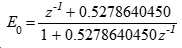
몇몇 실시예들에서, 제1 전역통과 응답은 1.0 및 0.527864045의 2-15 이내의 계수들을 가지고, 제2 전역통과 응답은 1.0 및 0.105572809의 2-15 이내의 계수들을 갖는다. In some embodiments, the first global pass response has coefficients within 2 -15 of 1.0 and 0.527864045, and the second global pass response has coefficients within 2 -15 of 1.0 and 0.105572809.
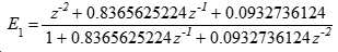
몇몇 실시예들에서, 제1 전역통과 응답은 1.0, 0.3644245374의 2-15 이내 및 0.01036373471의 2-15 이내의 계수들을 가지고, 제2 전역통과 응답은 1.0, 0.8365625224의 2-15 이내 및 0.09327361235의 2-15 이내의 계수들을 갖는다. In some embodiments, the first all-pass response is 1.0, with the 2-15 and within a factor of two less than the -15 0.01036373471 0.3644245374 of the second all-pass response is 1.0, less than 2 and -15 of 0.8365625224 0.09327361235 2 -15 . ≪ / RTI >
이러한 방식들로, 대역분할기 전달 함수들은 리플없이 1차 또는 2차 대역들로부터 얻어지며, 대역분할 오디오가 청취되는 어플리케이션에 적합하다. 실제 실행은 비-단위 계수를 반올림하는 것이 필요하며 공차 2-15는 16 비트의 일반적인 계수 크기를 반올림하는 것에 대응한다.In this way, the band splitter transfer functions are obtained from the primary or secondary bands without ripple, and are suitable for applications where band split audio is audible. Actual execution is required to round the non-unit coefficients and
본 발명의 제5 양태는 대역분할기를 제공하는데, A fifth aspect of the present invention provides a band splitter,
샘플링 레이트에서 신호 샘플들의 입력 스트림을 수신하는데 적용되는 입력;An input adapted to receive an input stream of signal samples at a sampling rate;
2개의 출력 스트림들을 제공하는데 적용되는 2개의 출력으로서, 각각의 출력 스트림은 입력 스트림의 샘플링 레이트의 절반을 갖는, 2개의 출력; Two outputs applied to provide two output streams, each output stream having two outputs, one half the sampling rate of the input stream;
하나의 입력 및 2개의 출력을 갖는 디-인터리빙 유닛으로서, 상기 디-인터리빙 유닛의 입력은 상기 대역분할기의 입력에 결합되고, 상기 디-인터리빙 유닛의 출력들은 상기 입력 스트림의 짝수번째 및 홀수번째 샘플들을 각각 포함하는, 디-인터리빙 유닛;1. A de-interleaving unit having one input and two outputs, the input of the de-interleaving unit being coupled to an input of the band divider, the outputs of the de-interleaving unit being input to an even- A de-interleaving unit;
제1 입력 및 출력을 각각 갖는 2개의 전역통과 필터들;Two all-pass filters each having a first input and an output;
2개의 입력 및 2개의 출력을 갖는 무손실 가산-및-감산 유닛으로서, 상기 가산-및-감산 유닛의 입력들 각각은 상기 2개의 전역통과 필터들의 출력들 중 하나에 각각 결합되고, 상기 가산-및-감산 유닛의 출력들 각각은 상기 대역분할기의 출력들 중 하나에 각각 결합되는, 무손실 가산-및-감산 유닛을 포함하고,A lossless addition and subtraction unit having two inputs and two outputs, each of the inputs of the add-and-subtract unit being each coupled to one of the outputs of the two all-pass filters, Subtracting unit, each of the outputs of the subtracting unit being coupled to one of the outputs of the band divider,
각각의 전역통과 필터는 시간 역순으로 상기 입력 스트림의 샘플들을 수신하는데 적용된다.Each global pass filter is applied to receive samples of the input stream in reverse chronological order.
이 방식으로, 전역통과 필터들의 가산 및 감산을 취함에 의한 작동은 적은 계수들로 양호한 식별이 얻어질 수 있도록 한다. 시간 역순 작동은 최대 위상 폴들을 갖는 전역통과 필터가 안정적으로 실행되는 것을 가능하게 한다. 이들은 대역들로의 분할로부터 위상 또는 진폭 에러가 발생하지 않도록 대응하는 대역결합기에서 최소 위상 폴들을 갖는 인과적 전역 필터에 의해 반전될 수 있다. In this way, operation by taking the addition and subtraction of the all-pass filters allows good identification to be obtained with fewer coefficients. Reverse in time operation enables an all-pass filter having maximum phase poles to be stably executed. These can be inverted by a causal global filter with minimum phase poles in the corresponding band combiner so that no phase or amplitude error occurs from the division into the bands.
몇몇 실시예들에서, 상기 대역분할기는 양자화기를 또한 포함하고, 각각의 전역통과 필터는 입력 스트림의 이미 수신된 샘플 및 이미 제공된 출력 샘플들과 입력 스트림의 이미 수신된 샘플에 후속하여 현재 샘플까지 및 현재 샘플을 포함하여 수신되는 입력 스트림의 샘플들의 선형 결합의 양자화 합과 동일한 출력 샘플을 제공하는데 적용된다. In some embodiments, the band splitter also includes a quantizer, wherein each global pass filter is configured to filter the previously received samples of the input stream and the already provided output samples and the already received samples of the input stream, Is applied to provide the same output sample as the quantized sum of the linear combination of samples of the input stream received including the current sample.
바람직하게는, 각각의 전역통과 필터는 상기 가산-및-감산 유닛의 출력들로부터 유도되는 피드백을 수신하는데 적용되는 제2 입력을 가지며, 이에 따라 상기 가산-및-감산 유닛은 상기 필터 내에 통합되게 된다.Preferably, each of the global pass filters has a second input applied to receive feedback derived from the outputs of the add-and-subtract units, whereby the add-and-subtract unit is integrated into the filter do.
이 방식으로, 대역분할기는 신호 경로에서 단지 하나의 양자화로 작동할 수 있으며, 대역 분할기 출력들이 오리지널 신호의 고주파 및 저주파 요소 각각에 대한 더 낮은 노이즈 근사치가 되는 것을 가능하게 한다. In this way, the band splitter can operate with only one quantization in the signal path, making it possible for the band divider outputs to be a lower noise approximation for each of the high and low frequency components of the original signal.
바람직하게는, 상기 대역분할기는 양자화기를 또한 포함하고, 각각의 전역통과 필터는 상기 입력 스트림의 이미 수신된 샘플 및 전역통과 필터의 제2 입력에 의해 이미 수신된 피드백 샘플들과 상기 이미 수신된 샘플에 후속하여 현재 샘플까지 및 현재 샘플을 포함하여 수신되는 입력 스트림의 샘플들의 선형 결합의 양자화 합과 동일한 출력 샘플을 제공하는데 적용된다.Advantageously, the band splitter also comprises a quantizer, wherein each global pass filter comprises feedback samples already received by a second input of an already received sample and an all-pass filter of the input stream, Followed by a quantization sum of the linear combination of samples of the input stream received up to the current sample and including the current sample.
몇몇 실시예들에서 계수들 340/32768 및 11941/32768을 갖는 I무한 임펄스 응답 'IIR'에 의해 2개의 필터들 중 하나가 특징화되고, 계수들 3056/32768 및 27412/32768을 갖는 IIR에 의해 다른 전역통과 필터가 특징화된다.In some embodiments, one of the two filters is characterized by an infinite impulse response " IIR " having coefficients 340/32768 and 11941/32768, and by IIR with coefficients 3056/32768 and 27412/32768 Other all-pass filters are characterized.
이 방식으로, 계수들은 리플없이 대역분할기 전달 함수들을 근사화하는 2차 전역통과들에 사용된다. 이 값들은 16 비트 계수들을 갖는 고정 소수점(point) 실행을 위해 반올림된다. In this way, the coefficients are used in the second order global passes to approximate the band divider transfer functions without ripple. These values are rounded for fixed point execution with 16-bit coefficients.
바람직한 실시예에서, 상기 대역분할기는:In a preferred embodiment, the band splitter comprises:
입력 및 출력을 갖는 블로킹 유닛; 및A blocking unit having an input and an output; And
입력을 갖는 결합 유닛을 추가로 포함하고,Further comprising a coupling unit having an input,
상기 블로킹 유닛은 블로킹 유닛의 입력에 나타내어지는 샘플들의 스트림을 수신하고, 상기 스트림을, 각각 시작 및 종료를 갖는, 샘플들의 오버랩 블록들로 분할하며, 블로킹 유닛의 출력에 오버랩 블록들을 제공하는데 적용되고, The blocking unit receives the stream of samples represented at the input of the blocking unit and divides the stream into overlap blocks of samples having start and end respectively and is applied to provide overlap blocks at the output of the blocking unit ,
상기 블로킹 유닛의 출력은 상기 전역통과 필터들의 제1 입력들에 결합되고;The output of the blocking unit being coupled to the first inputs of the all-pass filters;
상기 전역통과 필터들은 샘플들의 각각 오버랩 블록 내의 샘플들을 시간 역순으로 처리하고, 그들의 출력들에서 샘플들의 처리된 블록들을 제공하는데 적용되고The global pass filters are applied to process samples in each overlap block of samples in reverse chronological order and to provide processed blocks of samples at their outputs
상기 전역통과 필터들의 출력들은 상기 결합 유닛의 입력에 결합되고;The outputs of the all-pass filters being coupled to an input of the combining unit;
상기 결합 유닛은 그것의 입력에 나타내어지는 샘플들의 오버랩 처리된 블록들을 수신하여, 각각의 처리된 블록으로부터 처리된 블록의 끝으로부터 오버랩 부분을 버리고, 처리된 샘플들의 연속 스트림을 제공하는 나머지 부분들을 결합하는데 적용된다.The combining unit receives the overlap processed blocks of samples represented at its input, discards the overlap portion from the end of the processed block from each processed block, and combines the remaining portions providing a continuous stream of processed samples. .
이 방식으로, 샘플의 각각의 블록은 시간 역순으로 처리되어, 최대 위상 폴들이 안정적으로 실행되는 것을 가능하게 한다. 그러나 연속적인 블록들은 정상적인 순서로 처리될 수 있으므로, 대역분할이 한정된 미리보기와 함께 진행될 수 있다. 오버랩과 버려짐은 출력에 기여하는 샘플을 처리하기 전에 각각의 블록에서 대역분할기가 시작될 때 발생하는 트랜션트에 대한 시간을 제공한다. 시간 역순 처리로 인해, 이러한 트랜션트는 각각의 블록의 끝에서 발생한다. In this way, each block of samples is processed in reverse chronological order, making it possible for the maximum phase poles to be stably executed. However, since consecutive blocks can be processed in normal order, band splitting can proceed with limited previewing. The overlaps and discards provide time for transients that occur when the band splitter is started in each block before processing the samples contributing to the output. Due to temporal inverse processing, such transients occur at the end of each block.
본 발명의 제6 양태는 대역결합기를 제공하는데, A sixth aspect of the present invention provides a band combiner,
입력 양자화된 신호 샘플들의 제1 및 제2 스트림을 수신하는데 적용되는 2개의 입력들;Two inputs applied to receive the first and second streams of input quantized signal samples;
각각의 입력 스트림의 샘플링 레이트의 2배의 샘플링 레이트를 갖는 출력 스트림을 제공하는데 적용되는 출력;An output applied to provide an output stream having a sampling rate that is twice the sampling rate of each input stream;
가산 출력 및 감산 출력으로 각각 구성되는 2개의 입력들 및 2개의 출력들을 갖는 가산-및-감산 유닛;An add-and-subtracting unit having two inputs and two outputs, each of which is composed of an addition output and a subtraction output;
제1 입력 및 출력을 각각 갖는 2개의 전역통과 필터들; 및Two all-pass filters each having a first input and an output; And
2개의 입력들 및 1개의 출력을 갖는 인터리빙 유닛을 포함하고,An interleaving unit having two inputs and one output,
상기 가산-및-감산 유닛의 입력들은 상기 대역결합기의 입력들에 연결되고;Inputs of the add-and-subtract unit are connected to inputs of the band combiner;
상기 2개의 전역통과 필터들 각각의 제1 입력은 상기 가산-및-감산 유닛의 가산 출력 및 감산 출력에 각각 연결되고;A first input of each of the two all-pass filters is connected to an addition output and a subtraction output of the add-and-subtract unit, respectively;
상기 인터리빙 유닛의 입력들은 상기 전역통과 필터의 출력들에 결합되고;The inputs of the interleaving unit being coupled to the outputs of the all-pass filter;
상기 인터리빙 유닛의 출력은 상기 대역결합기의 출력에 결합되며, The output of said interleaving unit being coupled to the output of said band combiner,
상기 대역결합기는 무손실이다.The band combiner is lossless.
이 방식으로, 무손실 특성은, 본 발명에 따른 대역결합기와 본 발명에 따른 대역분할기로 구성된 시스템이 입력을 대역결합기로 정확하게 복사하는 것을 가능하게 함으로써, Kleinmann 및 Lacroix의 대역결합기의 작동을 향상시킨다. 따라서 Kleinmann 및 Lacroix의 위상 왜곡이 제거될 뿐만 아니라 대역분할기의 양자화들에 의해 도입된 노이즈가 대역결합기의 양자화에 의해 제거된다. In this way, the lossless nature improves the operation of the band combiner of Kleinmann and Lacroix by allowing the system consisting of the band combiner according to the invention and the band splitter according to the invention to accurately copy the input to the band combiner. Therefore, not only the phase distortion of Kleinmann and Lacroix is eliminated, but also the noise introduced by the quantizers of the band splitter is removed by quantization of the band combiner.
몇몇 실시예들에서, 가산-및-감산은 가산 및 감산을 취하기 전에 팩터 2에 의해(2배로) 그것의 입력들 중 하나를 스케일링한다. In some embodiments, the add-and-subtract scales one of its inputs (by a factor of two) by
이 방식으로, 가감산 매트릭스는 단위 결정 가산 및 감산 유닛을 이용하는 대역분할기로부터 발생하는, 2개의 입력에 대한 이득 차이를 2배로 수용할 수 있다.In this way, the add / subtract matrix can accommodate twice the gain difference for the two inputs, resulting from the band dividers using unit add and subtract units.
바람직하게는, 상기 대역결합기는 또한 양자화기를 포함하되, 각각의 전역통과 필터는 제1 입력에 의해 이미 수신된 샘플과 이미 제공된 출력 샘플들과 상기 이미 수신된 샘플에 후속하여 현재의 샘플까지 및 현재의 샘플을 포함하여 수신되는 입력 샘플들의 선형결합의 양자화 합과 동일한 출력을 제공하는데 적용된다.Advantageously, the band combiner further comprises a quantizer, wherein each of the all-pass filters comprises a sample already received by the first input, output samples already provided and subsequent to the already received sample, Lt; / RTI > is applied to provide the same output as the quantized sum of the linear combination of the input samples received.
바람직하게는, 상기 양자화기는 양측 전역통과 필터들 내에 있는 신호들을 공동으로 양자화하는데 적용되는 벡터 양자화기이다.Advantageously, said quantizer is a vector quantizer applied to collectively quantize signals within both side all-pass filters.
이 방식으로, 대역 결합기는, 상기 매트릭스화 및 필터링에 있어서 분리된 양자화 대신 단일 양자화를 가지고 바람직한 저 잡음 모드로 작동하는 대역결합기의 작동을 반전할 수 있다. In this manner, the band combiner can reverse the operation of the band combiner operating in the preferred low noise mode with single quantization instead of separate quantization in the matrixing and filtering.
바람직하게는, 상기 대역결합기는 2개의 입력과 2개의 출력을 갖는 벡터 양자화기를 포함하며,Advantageously, said band combiner comprises a vector quantizer having two inputs and two outputs,
상기 벡터 양자화기의 입력들은 2개의 전역통과 필터들의 각각의 출력들에 연결되고;The inputs of the vector quantizer being coupled to respective outputs of two global pass filters;
상기 벡터 양자화기의 출력들은 상기 대역결합기의 출력들에 연결되며;The outputs of the vector quantizer being coupled to the outputs of the band combiner;
각각의 전역통과 필터는 상기 벡터 양자화기의 출력들에 따라 유도되는 피드백을 수신하는데 적용되는 제2 입력을 갖는다. Each of the global pass filters has a second input applied to receive feedback derived from the outputs of the vector quantizer.
바람직하게는, 상기 대역결합기는 또한 양자화기를 포함하되, 각각의 전역통과 필터는 상기 전역통과 필터의 제1 입력에 의해 이미 수신된 샘플과 상기 피드백의 이미 제공된 샘플들 및 상기 이미 수신된 샘플에 후속하여 수신되되 현재의 샘플까지 및 현재의 샘플을 포함하는 입력 샘플들의 선형 결합의 양자화 합과 동일한 출력을 제공하는데 적용된다. Advantageously, the band combiner further comprises a quantizer, wherein each of the all-pass filters is configured to filter samples already received by the first input of the all-pass filter and subsequent samples of the feedback, And is applied to provide an output equal to the quantization sum of the linear combination of input samples received up to the current sample and including the current sample.
바람직하게는, 상기 대역결합기는 대역분할기에 의해 생성되는 신호들의 쌍을 소유하도록 구성되어, 상기 대역결합기의 출력이 상기 대역분할기에 의해 수신된 신호 샘플들의 스트림의 무손실 복제이다.Advantageously, said band combiner is configured to possess a pair of signals generated by a band splitter, the output of said band combiner being a lossless replica of a stream of signal samples received by said band splitter.
이 방식으로, 대역결합기의 무손실 작동은 위에 열거한 것과 같은 위상 왜곡이 없고 및 순 양자화 노이즈가 없는 장점을 제공하는 것은 분명하다. In this way, it is clear that the lossless operation of the band combiner provides the advantage of no phase distortion and no net quantization noise as listed above.
바람직하게는, 상기 대역결합기는 상태 변수들을 갖는 전역통과 필터를 포함하여, 상기 대역결합기가, 상기 상태 변수들의 동일한 초기화를 가지지만 2개의 경우들에 수신되는 입력 스트림에 차이를 가지면서, 제1 출력 스트림 및 제2 출력 스트림을 제공하기 위해 2회 작동된다면, 제1 출력 스트림과 제2 출력 스트림 간의 차이가 있거나 각각의 작동 후에 필터들의 상태들 간의 차이가 있을 것이다. Advantageously, the band combiner comprises an all-pass filter having state variables such that the band combiner has a first initialization of the state variables, but with a difference in the input stream received in two cases, If it is operated twice to provide an output stream and a second output stream, then there will be a difference between the first and second output streams, or there will be a difference between the states of the filters after each operation.
이 방식으로, 대역 결합기는 작동 후에 구별되는 입력들이 작동 후 여전히 구별 가능하고 따라서 무손실이기 때문에, 정보를 잃지 않는다는 것이 확인된다. In this way, it is confirmed that the band combiner does not lose information since the inputs that are distinguished after operation are still distinguishable and therefore lossless.
몇몇 실시예들에서, 계수들 340/32768 및 11941/32768을 갖는 IIR 응답에 의해 제1 전역통과 필터가 특징화되고, 계수들 3056/32768 및 27412/32768을 갖는 IIR 응답에 의해 제2 전역통과 필터가 특징화된다.In some embodiments, the first all-pass filter is characterized by an IIR response having coefficients 340/32768 and 11941/32768, and the second global pass is characterized by an IIR response with coefficients 3056/32768 and 27412/32768. The filter is characterized.
이 방식으로, 계수들은 리플없이 대역분할기 전달 함수들을 근사화하는 2차 전역통과들에 사용된다. 이 값들은 16 비트 계수들로 고정 소수점 실행을 위해 반올림된다. In this way, the coefficients are used in the second order global passes to approximate the band divider transfer functions without ripple. These values are rounded to 16-bit coefficients for fixed-point execution.
본 발명의 제7 양태는 무손실 대역분할기를 포함하는 인코더 및 무손실 대역결합기를 포함하는 디코더를 포함하는 전송 시스템을 제공하는데, A seventh aspect of the present invention provides a transmission system including an encoder including a lossless band divider and a decoder including a lossless band combiner,
상기 대역분할기 및 대역결합기 각각은 디더된 양자화기를 포함하는 전역통과 필터를 포함하고; Each of the band splitter and the band combiner comprising an all-pass filter including a dithered quantizer;
상기 전송 시스템은 또한 상기 대역분할기에 있는 양자화기 및 상기 대역결합기에 있는 양자화기를 위한 동기화된 디더(synchronised dither)를 구비한다.The transmission system also comprises a quantizer in the band splitter and a synchronized dither for a quantizer in the band combiner.
이 방식으로, 대역분할기에서의 양자화들은 디더링의 사용으로 유리한 한편, 동기화는 결합된 시스템의 무손실 거동을 보존한다. 만약 대역분할 신호가 직접 들린다면 그 양자화를 들을 수 있다.In this way, quantization in the band splitter is advantageous with the use of dithering, while synchronization preserves the lossless behavior of the combined system. If the band split signal is heard directly, the quantization can be heard.
본 기술분야에서 능숙한 사람들에 의해 이해될 것이지만, 본 발명은 무손실 재구축을 제공하는 샘플 신호들의 무손실 대역분할 및 대역결합을 위한 기술 및 장치들을 제공한다. 본 개시에 비추어 능숙한 사람들에게는 추가의 변형 및 꾸밈들이 명백할 것이다.As will be understood by those skilled in the art, the present invention provides techniques and apparatus for lossless band division and band combining of sample signals that provide lossless reconstruction. Additional modifications and additions will be apparent to those skilled in the art in light of this disclosure.
본 발명의 실시예들이 첨부된 도면을 참조로 상세히 설명될 것이다:
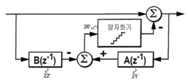
도 1은 공지된 손실성 IIR 대역분할기 및 대역결합기를 나타낸다;
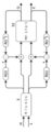
도 2는 위상 왜곡에 대한 개념적 보정과 함께 도 1의 대역분할기 및 대역결합기를 나타낸다;
도 3은 1차 IIR 대역분할기의 진폭 응답을 나타내는데, 실선은 LF 신호이고 점선은 HF 신호이다.
도 4는 2차 IIR 대역분할기의 진폭 응답을 나타내는데, 실선은 LF 신호이고 점선은 HF 신호이다.
도 5a는 공지된 무손실 IIR 필터 아키텍처를 나타낸다.
도 5b는 도 5a에 도시된 필터의 역을 나타낸다.
도 6은 한 쌍의 무작위로 초기화된 무손실 전역통과 필터들이 동일한 상태로 수렴하는는데 걸리는 시간의 히스토그램을 나타낸다.
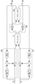
도 7은 도 2의 대역분할기와 유사하지만 전역통과 필터링과 무손실 가산 및 감산 작동들이 통합된 대역분할기를 나타낸다.
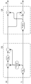
도 8은 도 7에 도시된 대역분할기에 대응하는 대역결합기를 나타낸다.
도 9a는 도 8에 도시된 대역 결합기의 작동들(31 및 13)의 확대를 나타낸다.
도 9b는 도 9a에 도시된 결합된 작동들의 간략화된 버전을 나타낸다.
도 10은 도 8에 도시된 대역결합기에 의해 수행되는 작동들의 벡터 양자화기 모습을 나타낸다.
도 11은 도 10에 도시된 벡터 양자화기에 의해 실행되는 양자화를 나타낸다.Embodiments of the present invention will now be described in detail with reference to the accompanying drawings, in which:
Figure 1 shows a known lossy IIR band splitter and band combiner;
Figure 2 shows the band splitter and band combiner of Figure 1 with a conceptual correction for phase distortion;
Figure 3 shows the amplitude response of the primary IIR band splitter where the solid line is the LF signal and the dashed line is the HF signal.
Figure 4 shows the amplitude response of a second order IIR band splitter where the solid line is the LF signal and the dashed line is the HF signal.
Figure 5A shows a known lossless IIR filter architecture.
Figure 5B shows the inverse of the filter shown in Figure 5A.
Figure 6 shows a histogram of the time it takes for a pair of randomly initialized lossless all-pass filters to converge to the same state.
Figure 7 shows a band splitter similar to the band splitter of Figure 2 but incorporating both global pass filtering and lossless addition and subtraction operations.
8 shows a band combiner corresponding to the band splitter shown in FIG.
FIG. 9A shows an enlargement of the
FIG. 9B shows a simplified version of the combined operations shown in FIG. 9A.
Figure 10 shows a vector quantizer of operations performed by the band combiner shown in Figure 8;
Fig. 11 shows the quantization performed by the vector quantizer shown in Fig.
타임-time- 리버스를Reverse 갖는 전역통과 Having a global pass
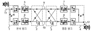
Kleinmann 및 Lacroix에 의해 앞서 언급된 논문으로부터 재생성된, 도 1의 종래 기술의 구조는 입력 샘플 신호(11)를 오리지널 레이트의 절반으로 샘플링된 2 개의 부대역 신호들(9 및 10)로 분할하고, 이후 출력 신호(12)를 제공하기 위해 그들을 재결합하도록 디자인되어 있다. 전형적으로, 부대역 신호(9)는 입력 신호(11)로부터 주로 저주파 정보를 포함하는 'LF' 신호이며, 부대역 신호(10)는 입력 신호(11)로부터 주로 고주파 정보를 포함하는 'HF' 신호이다. The prior art structure of Fig. 1, regenerated from the above-mentioned paper by Kleinmann and Lacroix, divides the
우리는 가산-및-감산 유닛(3)이 팩터(2)에 의한 전체 스케일링을 제외하고는, 가산-및-감산 유닛(2)의 효과를 반전시킨다는 것을 주목한다. 유닛들(2 및 3)은 동일할 수 있다. 따라서 도 1의 작동은 다음과 같이 설명될 수 있다:We note that the add-and-subtract
· 신호(11)은 디-인터리브(de-interleave) 유닛(1)에 의해 짝수 및 홀수 샘플 스트림들로 분할된다. The
·짝수 샘플들은 전달 함수 E0를 갖는 필터(5)에 의해 필터링되고 홀수 샘플들은 전달 함수 E1을 갖는 필터(6)에 의해 필터링된다.The even samples are filtered by a
·2개의 가산-및-감산 유닛들(2 및 3)은 부호 2에 의한 스케일링을 제외하고는 널(null) 효과를 함께 갖는다. The two add-and-subtract
·짝수 샘플들은 전달 함수 E1을 갖는 필터(7)에 의해 현재 필터링되고 홀수 샘플들은 전달 함수 E0를 갖는 필터(8)에 의해 현재 필터링된다.The even samples are currently filtered by
·짝수 및 홀수 샘플 스트림들은 인터리빙 유닛(4)에서 재결합된다. The even and odd sample streams are recombined in the
따라서, 디-인터리빙 유닛으로부터의 짝수 샘플들은 E0에 의해 이후 E1에 의해 필터링되고, 홀수 샘플들은 E1에 의해 이후 E0에 의해 필터링된다. 필터링이 가환적(commutative)이기 때문에 전체적으로 도 1의 효과는 진폭에 있어 팩터 2에 의해(2배로) 스트림(11)을 스케일링하고 전달 함수 E0.E1으로 그것을 필터링한다는 것이 명백하다. 또한 디-인터리빙 및 인터리빙 유닛들에서 z-1 요소로 인해 하나의 샘플의 지연이 있다. Thus, the even samples from the de-interleaved unit are then filtered by E 0 followed by E 1 , and the odd samples filtered by E 1 followed by E 0 . As the filtering is commutative, it is clear that the effect of Fig. 1 as a whole scales the stream 11 (by 2 times) by
만약 필터들(5 및 6)이 직선 경로라면, 즉 E0=1 및 E1=1인 경우, 신호(10)은 입력(11)의 제로-주파수 신호 요소에 대하여 제로 응답을 가질 것이며 유사하게 신호 9는 나이퀴스트 주파수, 즉 신호(11)의 샘플링 주파수의 절반에서 오리지널 신호 요소들에 대하여 제로 응답 신호를 가질 것이다. 따라서 매우 낮은 그리고 매우 높은 주파수들이 분리되었을 것이다. 다른 주파수들은 디-인터리빙 유닛 내에서 "z-1" 지연에 의해 생성된 주파수 의존 위상 쉬프트 때문에 불완전하게 분리된다. 필터들(5 및 6)의 목적은 이 위상 시프트를 대략적으로 보상하여 높은 그리고 낮은 주파수 간의 우수한 식별이 상당한 대역폭에 걸쳐 유지되도록 하는 것이다.If E 0 = 1 and E 1 = 1, then the
따라서 응답 E0는 저주파에서 신호(11)의 하나의 샘플 주기의 지연을 근사하는 E1의 그것에 대하여 낮은 주파수에서 위상 쉬프르틀 제공해야 한다. E0 및 E1이 오리지널 샘플 주파수의 절반에서 실행되기 때문에, 그들은 그러므로, 그 위상차가 로컬 샘플링 주파수에서 1/2 샘플 주기를 근사화하는 한 쌍의 전역통과 필터로 설계되어야만 한다. 우리는 적절한 디자인들을 나타낼 것이지만, 우선 도 1에 도시된 대역분할기와 대역결합기의 조합이 전역 통과이면서 따라서 위상 왜곡을 도입하는 전달 함수(E0.E1)를 갖는 문제점을 다룰 필요가 있다. 이 문제는 위에 언급된 Kleinmann과 Lacroix 논문에서 인식되었으나 전기통신 실무에서 일부 잔류 왜곡은 수용가능한 것으로 고려되었으나 완전히 무손실 솔루션은 찾지 못하였다.Therefore, the response E 0 must provide a phase shift at a low frequency to that of E 1 approximating the delay of one sample period of the
개념적으로, 원하지 않는 전달 함수(E0.E1)는 반전 필터 (E0.E1)-1를 이용하여 보정될 수 있다. 이 반전 필터가 결과적인(acausal) 중요한 실제적 어려움을 순간적으로 무시하면, 도 2에서 우리는 개념적인 반전 필터(E0.E1)-1를 필터들(5' 및 6')에 에 병합하고, 이제는 개념적 응답(E1 -1 및 E0 -1)을 각각 갖는다. Conceptually, the undesired transfer function (E 0 .E 1 ) can be corrected using an inverse filter (E 0 .E 1 ) -1 . If this inverse filter momentarily ignores the acausal significant practical difficulties, then in FIG. 2 we merge the conceptual inversion filter (E 0 .E 1 ) -1 into the filters 5 'and 6' , And now have conceptual responses (E 1 -1 and E 0 -1 ), respectively.
P. P. Vaidyanathan, S. K. Mitra and Y. Neuvo"에 의해 저 감도 IIR 디지털 필터 구현에 대한 새로운 접근법 들", IEEE Trans. 음향, 음성 및 신호 처리, vol. ASSP-34, no. 2, pp. 350-361, April 1986에는, 가산 및 감산이 Butterworth, Chebyshev 또는 타원형 응답을 제공하는 한 쌍의 전역통과 필터를 생성하는데 적합한 설계 절차가 제시되어 있다. New approaches to low sensitivity IIR digital filter implementation by P. P. Vaidyanathan, S. K. Mitra and Y. Neuvo ", IEEE Trans. Sound, voice and signal processing, vol. ASSP-34, no. 2, pp. 350-361, April 1986, presents a design procedure suitable for generating a pair of all-pass filters in which addition and subtraction provide a Butterworth, Chebyshev, or elliptical response.
제로 리플이 바람직하고 예리한 모서리가 바람직하지 않은 오디오 어플리케이션에 대하여, 우리는 다음의 필터들이 적합함을 확인하였다:For audio applications where zero ripple is desirable and sharp edges are undesirable, we have verified that the following filters are suitable:
1차:

2차:
이 문서에서 여기 그리고 이후에, z -1 은 부대역 샘플링 레이트에서 하나의 샘플의 지연을 나타낸다: 이는 실행에 적절하지만 Kleinmann과 Lacroix에서 사용된 규칙과는 다르다.Here and thereafter in this document, z -1 represents the delay of one sample at the subband sampling rate: this is appropriate for implementation, but different from the rules used in Kleinmann and Lacroix.
½의 스케일 팩터를 삽입하면, 저역통과 및 고역통과 응답들은 다음과 같이 주어진다:When inserting a scale factor of ½, the low-pass and high-pass responses are given as:
lopasslopass = (E = (E 1One -1-One +E+ E 00 -1-One )/) / 22 hipasshipass = (E = (E 1One -1-One -E-E 00 -1-One )/2)/2
전역통과 필터의 시간-역전(time-reverse)이 또한 그것의 반전(inverse)이라는 것은 잘 알려져 있다. 이것은 예를 들어 위의 E0에 대한 표현식에서 z -1 을 z로 대체하여 확인될 수 있는데, 이는 분자와 분모를 교환하는 것과 동일한 효과를 갖는다. It is well known that the time-reversal of the global pass filter is also its inverse. This can be confirmed, for example, by replacing z -1 with z in the expression for E 0 above, which has the same effect as exchanging numerator and denominator.
우리는 역-시간 처리가 반드시 비실용적인 것은 아니라는 것을 주목한다. 일부 소비자 어플리케이션에 있어서, 인코더는 오디오 신호를 LF 및 HF 요소로 분리하며, 이들은 개별적으로 전달되고 소비자의 디코더에 결합된다. 오디오 트랙의 사전 인코딩(pre-encoding)은 일반적으로 파일 대 파일 처리로 수행되며, 따라서 역-시간 처리는 순방향 처리보다 개념적으로 어려운 것이 아니다. 따라서, 결과적인 전역통과 필터들(E 1 -1 및 E 0 -1 )은 역 시간에 인과적(causal) 필터로 실행될 수 있다:We note that de-time processing is not necessarily impractical. In some consumer applications, the encoder separates the audio signal into LF and HF elements, which are individually delivered and coupled to the consumer's decoder. Pre-encoding of audio tracks is typically performed with file-to-file processing, and therefore reverse-time processing is not conceptually more difficult than forward processing. Thus, the resulting all-pass filters ( E 1 -1 and E 0 -1 ) can be implemented as causal filters in inverse time:
lopasslopass = = RevRev (E (E 1One +E+ E 00 )/) / 22 hipasshipass = = RevRev (E (E 1One -E-E 00 )/2)/2
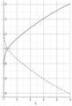
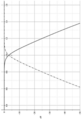
결과적인 저역통과 및 고역통과 응답들은 1차 필터의 경우 도 3에 도시되고 2차 필터의 경우 도 4에 도시되어 있다. 주파수는 스케일링되어, f=1이 교차 주파수이며, 이는 부대역 나이퀴스트 주파수와 같고, f=2는 오리지널 나이퀴스트 주파수이다. 이 디자인은 총 파워를 보존하며 저역통과 및 고역통과 커브들은 f=1에 대해 대칭이고, 이때 각각은 -3dB이다. 도 3의 1차 고역통과는 f=0.5에서 38dB 그리고 f=0.25에서 70dB에 의해 감쇠한다. 도 4의 2차 고역통과는 f=0.5에서 69dB 그리고 f=0.25에서 126dB에 의해 감쇠한다. 이러한 감쇠들은 이러한 디자인들의 낮은 계산 비용을 고려할 때 현저한 것으로 고려될 수 있다.The resulting lowpass and highpass responses are shown in FIG. 3 for a primary filter and in FIG. 4 for a secondary filter. The frequency is scaled so that f = 1 is the crossover frequency, which is equal to the subband Nyquist frequency, and f = 2 is the original Nyquist frequency. This design conserves total power, and the lowpass and highpass curves are symmetric about f = 1, where each is -3dB. The primary highpass of FIG. 3 is attenuated by 38 dB at f = 0.5 and by 70 dB at f = 0.25. The second order highpass of Figure 4 is attenuated by 69 dB at f = 0.5 and by 126 dB at f = 0.25. These attenuations can be considered significant when considering the low computational cost of these designs.
적절한 초기화를 통해, 이상의 처방은 대역분할기에 나타내어지는 신호의 대역결합기에 의한 정확한 재구축을 제공할 것이며, 전체적으로 정확한 산술을 가정한다. 우리는 이제 양자화된 산술을 이용할 때 필터링이 어떻게 무손실로 만들 수 있는지 검토한다. With proper initialization, the above presuppositions will provide accurate reconstruction by the band combiner of the signal represented in the band splitter, and assume an overall correct arithmetic. We now examine how filtering can be made lossless using quantized arithmetic.
무손실 최소-위상 Lossless minimum-phase IIRIIR 필터링Filtering
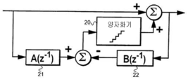
최소-위상 IIR 필터의 대중적인 "Direct form I" 실행은 WO 96/37048 "파형 데이터를 위한 무손실 코팅 방법"에서 언급된 바와 같이 쉽게 무손실로 만들어진다. 해당 문헌의 도 6c 및 도 6d는 여기의 5a 및 도 5b로 각각 재현된다. 해당 문헌의 다른 도면들은 동일한 또는 유사한 기능을 갖는 몇몇 다른 토폴로지를 나타낸다. 도 5a는 (1 + A(z-1)) / (1 + B(z-1))의 z-변환을 갖는 1차 무손실 IIR 필터를 나타내는 반면, 도 5b는 (1 + B(z-1)) / (1 + A(z-1))의 z- 변환를 갖는 대응 반전 필터를 나타낸다. The popular " Direct form I " implementation of the min-phase IIR filter is easily made lossless as mentioned in WO 96/37048 " Lossless coating method for waveform data ". Figures 6c and 6d of that document are reproduced respectively here 5a and 5b. Other figures in that document refer to some other topology having the same or similar functionality. Figure 5a is (1 + A (z -1) ) / (1 + B (z -1)), while Figure 5b indicates a first lossless IIR filter with a z- transform of the (1 + B (z -1 )) / (1 + A (z- 1 )).
도 5a에 대한 입력은 특정 스텝 크기로 양자화되는 것으로 가정되고, 양자화 기(20)는 동일한 스텝 크기로 양자화하며, 따라서 출력이 유사하게 양자화되는 것을 보장한다. 필터들(21 및 22)의 계수들은 유한 워드 길이를 가지며, 양자화기(20)는 또한 재순환 신호들이 필터(22)의 분수 계수들(fractional coefficients)에 의한 반복된 곱셈을 통해 임의로 긴 워드 길이를 획득하는 것을 방지한다.The input to FIG. 5A is assumed to be quantized to a particular step size, and the
도 5a의 작동은 결정적이며, WO 96/37048에서 설명된 바와 같이, 도 5a 및 도 5b의 캐스케이드는 도 5b의 출력에서 도 5a에 대한 입력의 정확한 복제를 재생성하며, 입력은 이미 양자화된 것으로 가정하고, 필터들(21' 및 22')의 상태 변수들은 필터들(21 및 22)의 상태 변수들과 같은 값들로 초기화되는 것으로 가정한다. 일부 디자인에서, 이 초기화는 명시적으로 수행되는 반면, 다른 것들은 2개의 필터들의 상태들 간의 확률적 수렴에 의존하며, 그러한 수렴이 얻어질 때까지가 아니라면 재생성이 무손실이 아닐 것이라는 것을 받아들인다. The operation of FIG. 5A is deterministic, and as described in WO 96/37048, the cascade of FIGS. 5A and 5B regenerates an exact duplicate of the input to FIG. 5A at the output of FIG. 5B, assuming the input is already quantized And the state variables of the filters 21 'and 22' are initialized to the same values as the state variables of the
결과적 IIR 필터들의 역-시간 실행The inverse-time execution of the resulting IIR filters
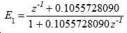
우리는 이제 1차 전역통과 필터(E 0 ) 및 그 역(E 0 -1 )이 어떻게 실행될 수 있는지를 보다 상세하게 나타내는데, 여기서:We now show in more detail how the first order all-pass filter ( E 0 ) and its inverse ( E 0 -1 ) can be implemented, where:
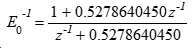
또는 보다 컴팩트하게:Or more compact:

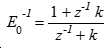
여기서, k=0.527864045이고, 특히 |k| < 1인 경우, E 0 의 분모가 최소-위상이고 이에 의해 E 0 가 표준 수단에 의해 실행될 수 있는 안정적인 그리고 인과적 필터인 것을 보장한다. Here, k = 0.527864045, and in particular, k | ≪ 1, it is ensured that the denominator of E 0 is the minimum-phase and that E 0 is a stable and causal filter that can be executed by standard means.
우리는 인코딩-디코딩 어플리케이션의 LF 경로를 고려하며, 샘플 값 {x i }의 입력 시퀀스가 인코더에서 E 0 -1 으로 나타내어져 전송된 시퀀스 {y i }를 생성하며, 이는 결과적으로 디코드에서 E 0 에 나타내어진다. 우리는 E 0 의 출력은 복귀 관계로 표현된 동일한 입력 시퀀스 {x i }가 되어야 한다고 요구한다:We encoding-decoding application, while considering the LF path, and generate sample values {x i} is the input sequence {y i} with E 0 shown as -1 in the encoder of the transmission sequence, which result in the decoded E 0 Lt; / RTI > We require that the output of E 0 be the same input sequence { x i } expressed in a return relationship:
![]()
![]()
인코더에서 E 0 -1 필터의 작동을 추론하기 위해, 우리는 y i-1 에 대하여 다음과 같이 풀었다:To infer the operation of the E 0 -1 filter in the encoder, we solve for y i -1 as follows:
![]()
![]()
인과율(causality)은 표기법 i = n .. 1로 표시되고 필터 E 0 -1 의 역 시간 실행을 반영하여, i가 감소하는 순으로 수행되도록 값 {y i }의 연산을 요구한다. 연산을 초기화하기 위해 인코더는 주어진 신호 값 {x i , i=1..n} 뿐만 아니라 y n 에 대한 값을 필요로 한다. y n 은 예를 들어 제로와 같이 임의로 선택될 수 있다. 또한 디코더는 초기화가 필요한데, 인코더가 필터링된 값 {y i , i=1..n}과 함께 오리지널 값 x 1 을 전송하는 편리한 방법이다. 이후, 디코더는 x 1 을 그것의 첫번째 출력 값으로 직접 사용할 뿐만 아니라 i=2부터 이어서 실행되는 나머지 계산에 대한 상태 초기화로 사용한다.The causality requires an operation of the value { y i } so that i is performed in decreasing order, represented by the notation i = n. 1 and reflecting the inverse time execution of the filter E 0 -1 . To initiate an operation, the encoder needs a value for y n as well as a given signal value { x i , i = 1..n}. y n may be arbitrarily selected, for example, as zero. The decoder also needs initialization, which is a convenient way for the encoder to send the original value x 1 along with the filtered value { y i , i = 1..n}. The decoder then uses x 1 as its first output value, as well as state initialization for the remainder of the calculations that run from i = 2 onward.
이러한 초기화가 주어지면 디코더는 이후 오리지널 신호 {x i }를 정확히 재구축할 수 있으며, 단지 산술적 반올림 에러 및 전송시 임의의 단어길이 자르기가 적용된다. E 1 과 E 1 -1 을 실행하기 위해 k=0.1055728090과 정확히 동일한 절차가 사용될 수 있다.Given this initialization, the decoder can then correctly reconstruct the original signal { x i }, and only an arithmetic rounding error and any word length truncation at transmission are applied. To execute E 1 and E 1 -1 , exactly the same procedure as k = 0.1055728090 can be used.
무손실 역-시간 처리Lossless inverse-time processing
무손실 처리를 위해 우리는 양자화된 입력 시퀀스 {x i }를 가정하고, 분수 계수들에 의한 곱셈의 결과는 양자화되어야 한다. 이 복구 관계는 이제 다음으로 대체된다:For lossless processing, we assume a quantized input sequence { x i }, and the result of the multiplication by fractional coefficients must be quantized. This recovery relationship is now replaced by:
![]()
![]()
![]()
![]()
여기서, Q i 는 입력 시퀀스 {x i }와 동일한 스텝 크기를 갖는 양자화를 나타낸다. 전송된 시퀀스 {y i }는 그러면 또한 동일한 스텝 사이즈로 양자화된 값을 포함한다. "Q i "의 접미사 "i"는 예를 들어 디더링된 양자화기에서와 같이 양자화 Q가 샘플마다 상이할 수 있음을 강조한다. 그러나, 인코더-디코더 쌍에서, 인코더에서 각각의 Q i 는 대응하는 디코더에서의 Q i 와 동일해야 하며, 이는 디더의 경우 인코더와 디코더 간에 동기화된, 동일한 의사랜덤 시퀀스 생성기에 의해 일반적으로 얻어진다. Where Q i represents a quantization having the same step size as the input sequence { x i }. The transmitted sequence { y i } then also contains a quantized value with the same step size. The suffix " i " of " Q i " emphasizes that the quantization Q may differ from sample to sample, e.g., as in a dithered quantizer. However, in an encoder-decoder pair, each Q i in the encoder must be equal to Q i in the corresponding decoder, which is generally obtained by the same pseudo-random sequence generator synchronized between the encoder and decoder in case of dither.
양자화 된 값이 스텝 사이즈의 정수배가 될 필요는 없다: 종종 펜딩 중인 특허출원 PCT/GB2015/050910에서 설명된 바와 같이 랜덤 옵셋을 갖는 양자화기를 이용하는 것이 유리하다. 다른 일반화는 신호들 {x i } 및 {y i }이 벡터-값일 수 있고, Q I 는 벡터 양자화기이다.The quantized value need not be an integer multiple of the step size: it is advantageous to use a quantizer with random offsets as described in patent application PCT / GB2015 / 050910, which is often pending. Another generalization is that signals { x i } and { y i } can be vector-values, and Q I is a vector quantizer.
블록단위 역-시간 인코더 처리Block-based reverse-time encoder processing
양자화되지 않은 경우와 무손실의 경우 모두, 완전한 출력 시퀀스 {x n }의 정확한 재구축은 예를 들어 값 x 1 에 의한 디코더 상태의 초기화를 요구한다. For both unquantized and lossless cases, the correct reconstruction of the complete output sequence { x n } requires the initialization of the decoder state, for example by the value x 1 .
정확한 산술을 사용하는 양자화되지 않은 처리에서, 올바른 초기화를 제공하는 것에 실패하는 것은 E 0 의 임펄스 응답에 비례하는 일시적인 에러가를 야기하고, 이는 E 0 가 1차일 때 감쇠 지수가 될 것이고 보다 일반적으로 감쇠된 사인파를 포함하여 선형 결합이 될 것이다. 이 일시적 에러는 i가 증가함에 따라 급격히 감소할 것이며, 약간의 샘플 또는 수십개의 샘플 후에는 일반적으로 중요하지 않게 될 것이다. In the non-quantization process using the correct arithmetic, it fails to provide a valid initialization causing a temporary error that is proportional to the impulse response of E 0, which
'무손실' 양자화된 처리를 사용하면, 부정확한 초기화가 유사한 초기 일시적 에러를 야기할 것이다. 일단 트랜션트가 사라지면, 디코딩 필터 E 0 의 상태가 인코딩의 상태와 동기화될 때까지 에러가 노이즈가 된다. 높은 차수의 필터로 이 상태 동기화가 절대 발생하지 않을 수 있지만, 이 문서에서 고려된 차수 2의 필터 E 0 에 대해 그리고 적절한 디더링된 양자화기를 이용하여 우리는 초기 트랜션트가 종료되고 에러가 노이즈로로 되는 시간으로부터 120 샘플 주기 후에 동기화가 얻어지지 않을 것이 10-12 미만의 확률이 있다고 예상하였다. 여기에 설명된 2-차 필터에 대하여, 초기 트랜션트는 약 30개의 샘플들이 96dB로 감소하거나 45개의 샘플들이 144dB로 감소한다. 이러한 필터들는 거의 완전한 확실성을 가지고 165 샘플 주기 후에 초기화의 독립 상태로 안정화된다. Using 'lossless' quantized processing, incorrect initialization will cause similar initial transient errors. Once the transient has disappeared, the error becomes noise until the state of the decoding filter E 0 is synchronized with the state of the encoding. This state synchronization may never occur with a high order filter, but for the filter E 0 of
이 추론은 이제 역-시간 필터링에 적용될 수 있다. 더 긴 파일의 시작으로부터 가져온 1165개의 샘블들의 블록이 역-시간으로 필터링되면, 처음 1000개의 필터링된 샘플은 이에 의해, 역순으로 필터링될 때 전체 파일의 처음 1000개 샘플들로 거의 완전한 확실성을 가지고, 동일하게 된다. This inference can now be applied to inverse-time filtering. If the block of 1165 samples taken from the beginning of the longer file is filtered in reverse-time, then the first 1000 filtered samples are thereby compared to the first 1000 samples of the entire file With almost complete certainty.
따라서 전체 파일의 역-시간 필터링은 불필요하다: 파일은 적어도 165 개의 샘플들에 의해 오버랩되는 블록으로 처리 될 수 있다. 블록은 임의의 순서, 특히 순방향 또는 병렬로 처리될 수 있으며, 역-시간 필터링이 각각의 블록 내에서 사용되고, 각각의 블록의 최종 165개의 샘플은 버려진다. 이 원칙은 또한 블록 처리 및 오버랩에 의해 도입된 지연에 따라, 샘플들의 스트림의 실시간 처리를 가능하게 한다.Thus, the inverse-time filtering of the entire file is unnecessary: the file can be treated as a block that is overlapped by at least 165 samples. The blocks may be processed in any order, in particular forward or parallel, and de-temporal filtering is used in each block and the last 165 samples of each block are discarded. This principle also enables real-time processing of the stream of samples in accordance with the delays introduced by block processing and overlap.
165개 샘플의 추정치는 100,000 번의 시도에 관한 도 6의 외삽에 기초하는데, 2개의 양자화된 필터가 215 차수 양자화 단계의 상이하고 무작위로 선택된 신호 값에 대응하는 상태로 초기화되었다. 상기 필터들은 이전에 주어진 계수들 k1=0.8365625224 및 k2=0.09327361235를 갖는 2차였으며, 그들 각각의 양자화기는 직사각형 확률 밀도 함수 및 하나의 양자화 단계와 동일한 피크 대 피크 진폭을 갖는 동일한 'RPDF' 디더로 디더링되었다. 도 6은 2개의 양자화기가 정렬되는데 소요된 시간의 히스토그램이다. 수직축은 실험 횟수의 10을 기준으로하는 대수(logarithm)이며, 수평축은 샘플 주기의 시간이다. 대부분의 시험에서 양자화기들은 동기화에 약 30 샘플 주기를 소요하고 동기화되지 않은 수는 이후 각각 10 샘플 주기마다 약 팩터 10으로 감소한다는 것을 알 수 있을 것이다.The estimates of the 165 samples are based on the extrapolation of FIG. 6 with respect to 100,000 trials, with two quantized filters initialized to a state corresponding to different and randomly selected signal values of the 2 15 order quantization step. The filters were quadrants with the previously given coefficients k1 = 0.8365625224 and k2 = 0.09327361235, and their respective quantizers were dithered with the same 'RPDF' dither with the same probability density function and the same peak-to- . 6 is a histogram of the time taken for the two quantizers to be aligned. The vertical axis is logarithm based on 10 of the number of experiments and the horizontal axis is the time of the sample period. In most tests it will be seen that the quantizers take about 30 sample periods of synchronization and the number of unsynchronized is reduced to about
2차 복귀 관계Second return relationship
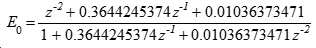
참고로 앞서 나타낸 복귀 관계는 2 차 필터링으로 확장된다. 예를 들어 E 0 을 취하면, 숫자 표현식:Note that the return relationship shown above extends to the second-order filtering. For example, taking E 0 , the numeric expression:

다음과 같이 표현될 수 있다:

여기서 k1 = 0.3644245374 및 k2 = 0.01036373471.Where k 1 = 0.3644245374, and k 2 = 0.01036373471.
디코딩 및 인코딩 식은 이제 다음과 같다:The decoding and encoding equations are now:
![]()
![]()
![]()
![]()
이는 개념적 필터들 E 0 및 E 0 -1 에 각각 대응한다. 인코더에 대한 초기화 조건들은 제로와 같은 임의의 편리한 값이 y n-1 및 y n 양에 대해 사용될 수 있으며, 이는 참조되지만 연산되지는 않는다는 것이다. 인코더는 필터링된 값 {yi, i = 1..n}과 함께 오리지널 값 x 1 및 x 2 를 전송함으로써 디코더를 초기화할 수 있다. 이후 디코더는 x 1 및 x 2 를 그것의 처음 2개의 출력 값으로 사용할 뿐만 아니라 그들을 i=3부터 실행되는 나머지 연산에 대한 상태 초기화로 사용한다. Which correspond to the conceptual filters E 0 and E 0 -1 , respectively. The initialization conditions for the encoder are that any convenient value, such as zero, can be used for y n-1 and y n quantities, which is referenced but not computed. The encoder can initialize the decoder by sending the original values x 1 and x 2 along with the filtered values {yi, i = 1..n}. Then the decoder not only uses x 1 and x 2 as its first two output values, but also uses them as state initialization for the remainder of the computation starting from i = 3 .
최초 수십개의 디코딩된 샘플에 대하여 정확한 재구축이 요구되지 않는다면, 초기화는 대안적으로 생략될 수 있다. If accurate reconstruction is not required for the first few dozen decoded samples, initialization may alternatively be omitted.
무손실 가산 및 감산Lossless Addition and Subtraction
도 2는 대역분할기 내의 가산 및 감산 네트워크(2) 및 대역결합기 내의 반전 가산 및 감산 네트워크(3)를 나타낸다. 무손실 전역통과를 통합한 무손실 전역통과 네트워크(16)을 나타내기 위해 대역분할기 및 대역결합기가 도 7 및 도 8에 다시 도시되어 있다.Figure 2 shows the addition and
결과적 필터들을 실행하는 것의 위의 논의에서 우리는 유닛들(2 및 3)의 구성에 대해 2의 스케일링을 기꺼이 도입한다. 그러나 우리는 무손실 작동 상으로 이동할 때, 우리는 필터(7과 8)로의 입력을 필요로 하기 때문에, 이 2의 팩터는 필터(5' 및 6')로부터의 출력을 정확하게 무손실 복제하는데 어색하다. 우리는 이 문제를 다루는 여러가지 방법을 제시한다.In the above discussion of implementing the resulting filters we are willing to introduce a scaling of two for the configuration of
가장 직접적인 접근법은 2에 의한 스케일링을 유닛(3)에 포함하여, 유닛(2)의 정확한 반전이 되도록 하는 것이다.The most direct approach is to include scaling by 2 in
따라서, 유닛(2)는 다음과 같이 연산한다:Thus, the
그리고 유닛(3)은 다음과 같이 연산한다:The

이것은 0.5에 의한 스케일링과 결합된 유닛(2)의 복제이다.This is a duplication of
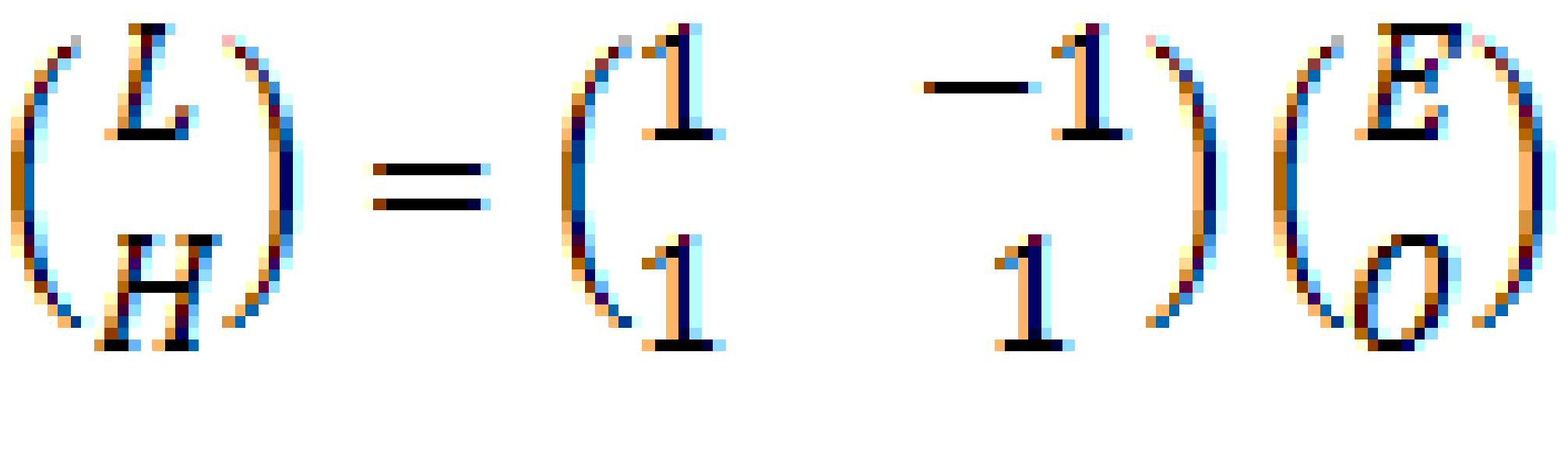
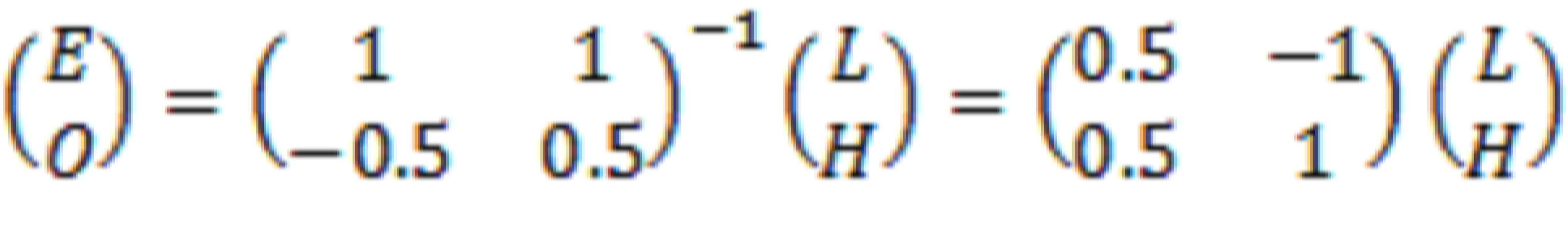
그러나 이 실행은 Lf 및 Hf 신호의 무손실 압축을 포함하는 시스템의 일부로 사용하기에 어색한데, E 및 O가 독립적으로 양자화된 값일 때, L 및 H는 그렇지 않기 때문이다. 결정자 -2를 갖는 전달 함수 ![]()
![]()
이 문제를 피하기 위해, 가산 및 감산 유닛(2)는 바람직하게는 결정자 ±1을 가지며, 합리적인 선택은 가산 및 반감산(half difference)이 되는데, 다음과 같다:To avoid this problem, the addition and
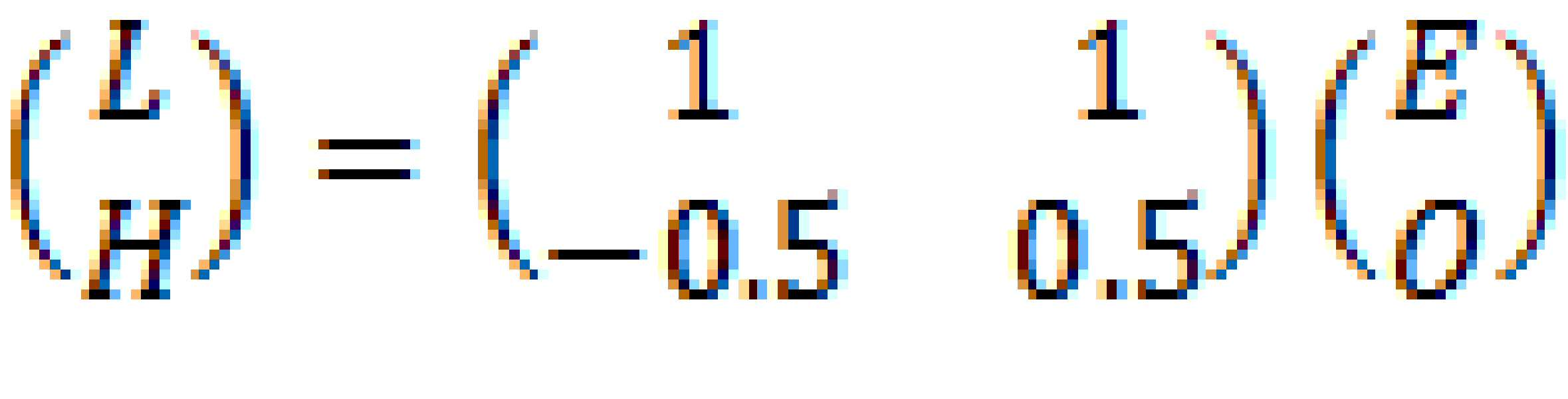
그리고, 따라서 유닛(3)은 다음과 같이 연산한다: And, therefore, the
0.5(O - E)의 연산은 양자화를 요구하는데, 이는 밴드분할기의 Hf 출력으로 추가의 노이즈를 도입하지만, 다음과 같은 무손실 방식으로 수행될 수 있다:The operation of 0.5 (O - E) requires quantization, which introduces additional noise into the Hf output of the band divider, but can be performed in the following lossless manner:
L = E + OL = E + O
H = O - Q(0.5L)H = O - Q (0.5 L)
그리고 유닛(3)에 대한 반전 작동은 다음과 같다:And the inversion operation for the
O = H + Q(0.5L)O = H + Q (0.5L)
E = L - O E = L - O
무손실 가산 및 감산과 전역통과의 통합Integration of Lossless Addition and Subtraction with Global Passing
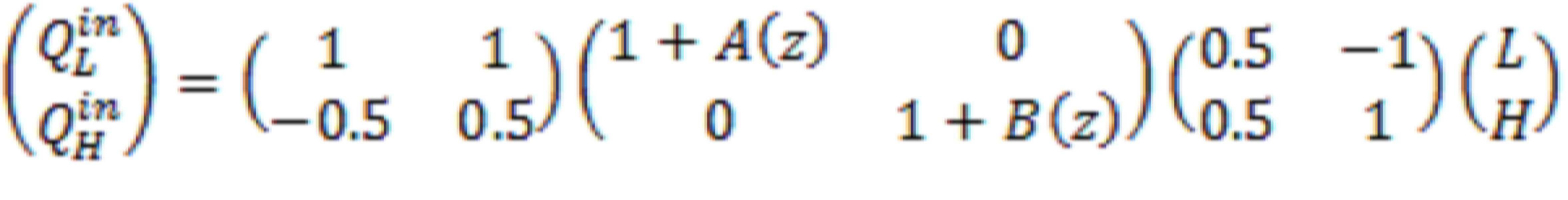
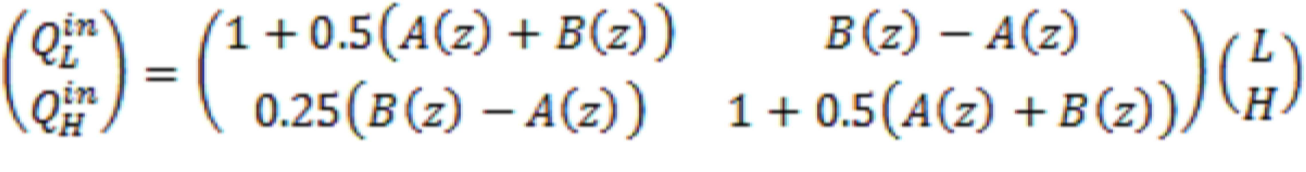
추가로, 가산 및 감산 작동들과 함께 전역통과 필터링을 통합함으로써 Lf 출력에서 양자화 노이즈의 양을 저감하는 것이 가능하다. 이는 대역분할기의 Lf 출력이 대역폭 확장 데이터에 액세스하지 못하는 사람들에 의해 청취될 수 있는 WO2013186561에 개시된 바와 같은 시스템에서 특히 유리하다. 또한, Hf 오디오 경로에서 추가의 양자화가 필요하지 않다.In addition, it is possible to reduce the amount of quantization noise at the Lf output by integrating the global pass filtering with the addition and subtraction operations. This is particularly advantageous in a system such as that disclosed in WO2013186561 in which the Lf output of the band splitter can be listened to by those who do not have access to the bandwidth extension data. Also, no additional quantization is required in the Hf audio path.
이는 도 7 및 도 8에 도시되어 있는데, 가산 및 감산 작동들(2 및 14)이 다음에 의해 실행되도록 의도된다:This is illustrated in FIGS. 7 and 8, in which the addition and
![]()
![]()
그리고 반전 가산 및 감산 작동들(3, 14 및 15)은 다음에 의해 실행되도록 의도된다:And the inverting addition and
![]()
![]()
마지막 섹션과 대조적으로, 이들은 이제 정확한 산술로 수행될 수 있다.In contrast to the last section, these can now be performed with exact arithmetic.
도 7은 대역분할기에서 부호 5', 6' 및 2의 재구성을 나타낸다.7 shows the reconstruction of the
필터(16)는 전역통과 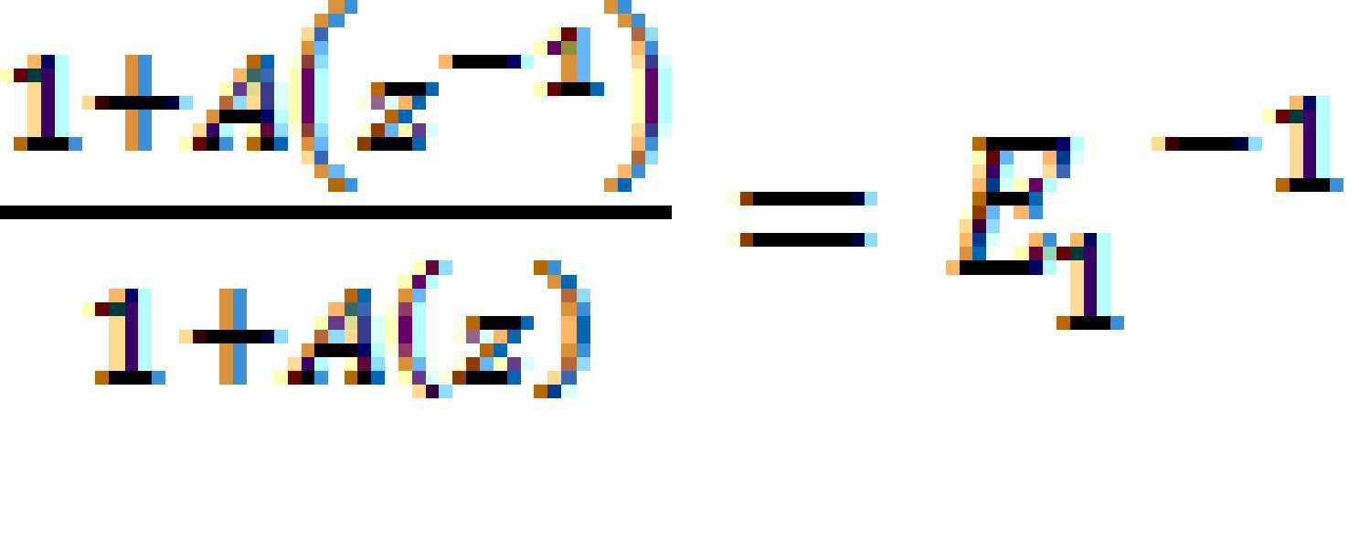
도 8은 밴드결합기의 작동을 나타낸다. 만약 도 8이 도7의 출력에 공급된다면, 작동(3)은 도 7의 작동(15)를 복제하여 필터 A(Z) 및 B(Z)에 대한 입력들이 도 7의 그들의 입력들을 복제하는 것을 보장한다. 만약 우리가 도 8의 이전 출력들이 도 7의 입력들에 복제되었고 양자화(31)가 양자화(30)이 가산된 것과 동일한 양자화 에러를 감산하였다고 가정하면, 우리는 도 8이 도 7의 작동을 정확히 반전한다고 유도적으로 결론내릴 수 있다.Figure 8 shows the operation of a band combiner. If Fig. 8 is supplied to the output of Fig. 7, act (3) replicates
우리는 이제 양자화기(30)의 부정된(negated) 양자화 에러를 갖기 위해 양자화기들(31)이 충족해야하는 조건들이 무엇인지를 고려한다.We now consider what conditions the
첫째로, 2개의 출력 값이 입력 값으로부터 등거리에 있는 상황에 대한 고려가 필요하다. 양자화기(30)가 -∞쪽으로 타이를 만든다(round a tie)면 양자화기(31)는 +∞쪽으로 타이를 만들어야 한다. (이는 대역결합기 양자화기가 이제 사이드 체인 측쇄 변화를 양자화하기보다는 주 신호 경로에 있기 때문에 도 5a 및 5b의 상황과 상이하다).First, consider the situation where the two output values are equidistant from the input values. If the
둘째로, 도 7의 입력들 및 출력들이 스텝사이즈 Δ의 배수로 양자화된다고 가정하면, 도 8로부터의 출력들도 마찬가지일 것이다. 그러나 그들은 다음과 같은 반전 가산 및 감산 매트릭스에 의해 양자화기(31)의 출력들로부터 유도된다Second, assuming that the inputs and outputs of Fig. 7 are quantized in multiples of the step size?, The outputs from Fig. 8 would be the same. However, they are derived from the outputs of the
![]()
![]()
만약 E와 O가 모두 Δ의 짝수배이거나 모두 Δ의 홀수배라면, L은 Δ의 짝수 배가 될 것이고 H는 Δ의 배수가 될 것이다. 그러나 E와 O가 반대 홀짝(opposite parity)이라면, L은 Δ의 홀수배가 될 것이고 H는 Δ/2의 홀수배가 될 것이다.If both E and O are both an even multiple of Δ or an odd multiple of Δ, L will be an even multiple of Δ and H will be a multiple of Δ. But if E and O are opposite parity, L will be an odd multiple of Δ and H will be an odd multiple of Δ / 2.
따라서 도 8의 밴드결합기는 L을 먼저 양자화할 것을 필요로 하고, 이후 L이 짝수 또는 홀수인지에 따라 Δ의 배수 또는 Δ의 배수 + Δ/2 중 하나에 H를 각각 양자화할 것을 필요로 한다. Thus, the band combiner of FIG. 8 needs to quantize L first and then needs to quantize H to one of either a multiple of A or a multiple of A + A / 2, depending on whether L is even or odd.
이를 하는 한가지 방법은 QH에 대해 Δ의 정수 값으로 양자화하는 양자화기를 이용하기 전에 L의 양자화된 값의 절반을 더하고 이후 나중에 다시 이를 감산한다. 이러한 작동(31)의 확장은도 9a에 도시되어 있으며, 이는 또한 반전 가산 및 감산을 실행하는 다음 작동(13)을 확장한다One way to do this is to add half of the quantized value of L before using a quantizer that quantizes to an integer number of delta for Q H and then subtract it again later. The expansion of this
![]()
![]()
0.5L을 더하는 부호 13의 작동은 그것을 감산하는 H에서의 작동을 취소하고, 결합된 작동은 도 9b에 도시된 바와 같이 간략화한다.The operation of the
도 10에 도시된 대안적 관점은 도 8의 작동들(14, 31 및 13)이 도 11에 예시 된 양자화를 실행하는 벡터 양자화기(32)를 형성한다는 것이다. 점들은 EO 공간에서의 양자화된 출력들이다. 사선 사각형들은 각각의 출력 값으로 양자화된 영역들이다. L 및 H 축들 또한 도시되어 있으며, 이러한 축들에 대해 양자화 영역들은 정사각형이며 축이 정렬된다. 그러나 교대의 L 열들은 옵셋되어 벽돌모양 패턴을 형성한다.An alternative view shown in FIG. 10 is that
산술적 변형Arithmetic transformation
본 발명의 본질에 영향을 미치지 않고 산술을 재배열하는 많은 방법이 있다는 것이 이해될 것이다.It will be appreciated that there are many ways to rearrange arithmetic without affecting the essence of the present invention.
예를 들어, 도 8은 입력으로부터 양자화기 입력으로의 신호 경로를 다음과 같이 표현한다:For example, Figure 8 represents the signal path from the input to the quantizer input as follows:
이는 다음으로 변형될 수 있다:This can be transformed into the following:
가산 및 감산 작동들을 갖는 2개의 필터들이, L/H 및 ![]()
![]()
![]()
![]()
Claims (35)
상기 오리지널 스트림을, 상기 오리지널 스트림의 짝수 및 홀수 샘플들을 각각 나타내는 2개의 중간 스트림으로 리포맷하는 단계;
2개의 출력 서브스트림을 제공하도록 상기 2개의 중간 스트림을 필터링 및 매트릭스화하는 단계를 포함하고,
상기 필터링 및 매트릭스화 단계는:
- 샘플들을 갖는 양자화된 신호를 생성하기 위해 양자화기를 이용하는 단계;
- 시간 역순으로 양자화된 신호 샘플들을 생성하는 단계; 및
- 이미 생성된 양자화된 신호의 샘플들로부터 유도되는 피드백에 따라 양자화된 신호 샘플들을 생성하는 단계를 포함하고,
각각의 출력 서브스트림은 최대 위상 폴들을 포함하는 각각의 전달 함수에 의해 각각의 중간 스트림에 관련되는, 방법.A method for separating an original stream of quantized signal samples having an original sampling rate into two output substreams of quantized signal samples having half the original sampling rate, said two output substreams comprising a high frequency component of the original stream And low-frequency components, respectively, the method comprising:
Reforming the original stream into two intermediate streams each representing even and odd samples of the original stream;
Filtering and matrixing the two intermediate streams to provide two output substreams,
Wherein the filtering and matrixing step comprises:
- using a quantizer to generate a quantized signal having samples;
- generating quantized signal samples in reverse chronological order; And
Generating quantized signal samples according to feedback derived from samples of quantized signals already generated,
Wherein each output substream is associated with a respective intermediate stream by a respective transfer function comprising maximum phase poles.
임의의 출력 서브스트림에 대하여, 중간 서브스트림들 양쪽으로부터의 상기 전달 함수는 동일한 DC 이득 크기를 갖는, 방법. The method according to claim 1,
Wherein for any output substream, the transfer function from both intermediate substreams has the same DC gain magnitude.
상기 필터링 및 매트릭스화 단계는:
상기 2개의 중간 스트림들의 샘플들의 오버랩 블록들을 처리하는 단계;
다른 블록과의 오버랩에 대응하는 샘플들의 각각 처리된 블록의 최종 부분을 버리는 단계; 및
샘플들의 각각 처리된 블록의 나머지 부분들을 결합하는 단계를 포함하는, 방법.3. The method according to claim 1 or 2,
Wherein the filtering and matrixing step comprises:
Processing overlap blocks of samples of the two intermediate streams;
Discarding a last portion of each processed block of samples corresponding to an overlap with another block; And
And combining the remaining portions of each processed block of samples.
상기 2개의 출력 서브스트림들은 상기 오리지널 양자화된 스트림이 적절히 초기화된 대역결합기에 의해 정확하게 복원되도록 하는 것에 요구되는 정보를 함께 포함하는, 방법.4. The method according to any one of claims 1 to 3,
Wherein the two output substreams together contain information required to cause the original quantized stream to be correctly restored by a suitably initialized band combiner.
어떠한 2개의 개별 입력 스트림들도 상기 동일한 출력 서브스트림들 및 상기 필터 내의 잔류 상태 모두를 생성하지 않는, 방법. 5. The method according to any one of claims 1 to 4,
No two separate input streams produce both the same output substreams and the residual state in the filter.
상기 필터링 및 매트릭스화 단계는:
2개의 필터링된 중간 스트림들을 생성하기 위해 2개의 중간 스트림들을 필터링하는 단계; 및
2개의 출력 서브스트림을 생성하기 위해 상기 필터링된 중간 스트림들을 매트릭스화하는 단계를 포함하는, 방법. 6. The method according to any one of claims 1 to 5,
Wherein the filtering and matrixing step comprises:
Filtering the two intermediate streams to produce two filtered intermediate streams; And
And matlating the filtered intermediate streams to produce two output substreams.
상기 매트릭스화 단계는 가감산 매트릭스를 이용하여 수행되는, 방법.The method according to claim 6,
Wherein the matrixing step is performed using an additive-subtraction matrix.
상기 출력 서브스트림들은 추가의 양자화없이 인버터블 리니어 프로세싱에 의해 상기 양자화된 신호로부터 유도되는, 방법.8. The method according to any one of claims 1 to 7,
Wherein the output substreams are derived from the quantized signal by inverter blunar processing without further quantization.
2개의 양자화된 중간 서브스트림들을 제공하기 위해 2개의 부대역 스트림들을 매트릭스화 및 필터링하는 단계; 및
상기 출력 스트림을 제공하기 위해 2개의 양자화된 중간 서브스트림들을 인터리빙하여 상기 중간 서브스트림들이 각각 상기 출력 스트림의 짝수 및 홀수 샘플들이 되도록 하는 단계를 포함하고,
각각의 중간 서브스트림은 최대 위상 제로를 포함하는 무한 임펄스 응답 'IIR'인 각각의 전달 함수에 의해 각각의 부대역 스트림에 관련되어지고
상기 매트릭스화 및 필터링 단계는 상기 출력 스트림이 각각의 부대역 스트림의 양자화된 신호 샘플들이 적절히 초기화된 대역분할기에 의해 정확하게 복원되는 것을 허용하기 위해 요구되는 정보를 포함하는 것을 보장하도록 구성되는 양자화를 포함하는, 방법. A method for combining two subband streams of quantized signal samples, each having a subband sampling rate, the method comprising: providing an output stream of quantized signal samples having twice the subband sampling rate, Frequency components and low-frequency components represented by each of the two sub-band streams, the method comprising:
Matrixing and filtering the two sub-band streams to provide two quantized intermediate sub-streams; And
Interleaving the two quantized intermediate substreams to provide the output stream so that each of the intermediate substreams is an even and an odd sample of the output stream,
Each intermediate sub-stream is associated with a respective sub-band stream by a respective transfer function that is an infinite impulse response " IIR " comprising a maximum phase zero
The matrixing and filtering step includes quantization configured to ensure that the output stream includes information required to allow quantized signal samples of each subband stream to be correctly reconstructed by a suitably initialized band splitter How to.
임의의 부대역 스트림에 대하여, 양 중간 스트림들에 대한 전달 함수는 동일한 DC 이득 크기를 갖는, 방법. 12. The method of claim 11,
Wherein for any subband streams, the transfer function for both intermediate streams has the same DC gain size.
상기 2개의 부대역 스트림들을 매트릭스화 및 필터링하는 단계는:
매트릭스화된 서브스트림들을 생성하기 위해 2개의 부대역 스트림들을 매트릭스화하는 단계; 및
2개의 양자화된 중간 서브스트림들을 생성하기 위해 2개의 상이한 양자화된 필터들로 매트릭스화된 서브스트림을 각각 필터링하는 단계를 포함하는, 방법.13. The method according to claim 11 or 12,
The step of matrixing and filtering the two sub-band streams comprises:
Matrixing the two sub-band streams to produce matrixed sub-streams; And
And filtering each of the sub-streams matrixed with two different quantized filters to produce two quantized intermediate sub-streams.
상기 매트릭스화 단계는 양자화를 포함하는, 방법.14. The method of claim 13,
Wherein the matrixing step comprises quantization.
상기 필터링 단계는 상기 2개의 필터들을 가로질러 공동으로 양자화하는 벡터 양자화기에 의해 수행되는 양자화를 포함하는, 방법.The method according to claim 13 or 14,
Wherein the filtering step comprises quantization performed by a vector quantizer that jointly quantizes across the two filters.
상기 2개의 부대역 스트림들 각각으로부터 상기 2개의 중간 서브스트림들 각각으로의 4개의 전달 함수들 모두는 전역통과인, 방법. 16. The method according to any one of claims 11 to 15,
Wherein all four transfer functions from each of the two sub-band streams to each of the two intermediate substreams are global pass.
제1 전역통과 응답은 1.0 및 0.527864045의 2-15 이내의 계수들을 가지고, 제2 전역통과 응답은 1.0 및 0.105572809의 2-15 이내의 계수들을 갖는, 방법.17. The method of claim 16,
Wherein the first global pass response has coefficients within 2 -15 of 1.0 and 0.527864045, and the second global pass response has coefficients within 2 -15 of 1.0 and 0.105572809.
제1 전역통과 응답은 1.0, 0.3644245374의 2-15 이내 및 0.01036373471의 2-15 이내의 계수들을 가지고, 제2 전역통과 응답은 1.0, 0.8365625224의 2-15 이내 및 0.09327361235의 2-15 이내의 계수들을 갖는, 방법.17. The method of claim 16,
A first all-pass response is 1.0, with the 2-15 and within a factor of two less than the -15 0.01036373471 0.3644245374 of the second all-pass response has a modulus of less than 2 -15 2 -15 within and 0.09327361235 1.0, 0.8365625224 / RTI >
샘플링 레이트에서 신호샘플들의 입력 스트림을 수신하는데 적용되는 입력;
2개의 출력 스트림들을 제공하는데 적용되는 2개의 출력으로서, 각각의 출력 스트림은 입력 스트림의 샘플링 레이트의 절반을 갖는, 2개의 출력;
하나의 입력 및 2개의 출력을 갖는 디-인터리빙 유닛으로서, 상기 디-인터리빙 유닛의 입력은 상기 대역분할기의 입력에 결합되고, 상기 디-인터리빙 유닛의 출력들은 상기 입력 스트림의 짝수번째 및 홀수번째 샘플들을 각각 포함하는, 디-인터리빙 유닛;
제1 입력 및 출력을 각각 갖는 2개의 전역통과 필터들로서, 각각의 전역통과 필터의 제1 입력은 상기 디-인터리빙 유닛의 각각의 출력에 결합되는, 2개의 전역통과 필터들; 및
2개의 입력 및 2개의 출력을 갖는 무손실 가산-및-감산 유닛으로서, 상기 가산-및-감산 유닛의 입력들 각각은 상기 2개의 전역통과 필터들의 출력들 중 하나에 각각 결합되고, 상기 가산-및-감산 유닛의 출력들 각각은 상기 대역분할기의 출력들 중 하나에 각각 결합되는, 무손실 가산-및-감산 유닛을 포함하고,
각각의 전역통과 필터는 시간 역순으로 상기 입력 스트림의 샘플들을 수신하는데 적용되는, 대역분할기. As a band splitter,
An input adapted to receive an input stream of signal samples at a sampling rate;
Two outputs applied to provide two output streams, each output stream having two outputs, one half the sampling rate of the input stream;
1. A de-interleaving unit having one input and two outputs, the input of the de-interleaving unit being coupled to an input of the band divider, the outputs of the de-interleaving unit being input to an even- A de-interleaving unit;
Two global pass filters each having a first input and an output, the first input of each global pass filter being coupled to a respective output of the de-interleaving unit; And
A lossless addition and subtraction unit having two inputs and two outputs, each of the inputs of the add-and-subtract unit being each coupled to one of the outputs of the two all-pass filters, Subtracting unit, each of the outputs of the subtracting unit being coupled to one of the outputs of the band divider,
Wherein each of the global pass filters is applied to receive samples of the input stream in reverse chronological order.
각각의 전역통과 필터는 상기 가산-및-감산 유닛의 출력들로부터 유도되는 피드백을 수신하는데 적용되는 제2 입력을 가지며, 이에 따라 상기 가산-및-감산 유닛은 상기 필터 내에 통합되는, 대역분할기. 21. The method of claim 20,
Wherein each of the all-pass filters has a second input applied to receive feedback derived from the outputs of the add-and-subtract unit, whereby the add-and-subtract unit is integrated within the filter.
양자화기를 추가로 포함하고, 각각의 전역통과 필터는 상기 입력 스트림의 이미 수신된 샘플 및 이미 제공된 출력 샘플들과 상기 이미 수신된 입력 샘플에 후속하여 현재 샘플까지 및 현재 샘플을 포함하여 수신되는 입력 샘플들의 선형 결합의 양자화 합과 동일한 출력 샘플을 제공하는데 적용되는, 대역분할기.21. The method of claim 20,
And wherein each global pass filter comprises an already sampled and already provided output samples of said input stream and an input sample that is received subsequent to said already received input sample, Wherein the quantizer is applied to provide an output sample equal to the quantization sum of the linear combination of < RTI ID = 0.0 >
양자화기를 또한 포함하고, 각각의 전역통과 필터는 상기 입력 스트림의 이미 수신된 샘플 및 전역통과 필터의 제2 입력에 의해 이미 수신된 피드백 샘플들과 상기 이미 수신된 샘플에 후속하여 현재 샘플까지 및 현재 샘플을 포함하여 수신되는 입력 스트림의 샘플들의 선형 결합의 양자화 합과 동일한 출력 샘플을 제공하는데 적용되는, 대역분할기.22. The method of claim 21,
And wherein each global pass filter comprises feedback samples already received by a second input of an already received sample of the input stream and a global pass filter and a second quantizer of the current samples after the already received sample, Wherein the quantizer is applied to provide an output sample equal to a quantization sum of a linear combination of samples of a received input stream including a sample.
계수들 340/32768 및 11941/32768을 갖는 I무한 임펄스 응답 'IIR'에 의해 2개의 필터들 중 하나가 특징화되고, 계수들 3056/32768 및 27412/32768을 갖는 IIR에 의해 다른 전역통과 필터가 특징화되는, 대역분할기. 24. The method according to any one of claims 20 to 23,
One of the two filters is characterized by an I infinite impulse response 'IIR' with coefficients 340/32768 and 11941/32768, and another IIR with coefficients 3056/32768 and 27412/32768, Characterized by a band splitter.
입력 및 출력을 갖는 블로킹 유닛; 및
입력을 갖는 결합 유닛을 추가로 포함하고,
상기 블로킹 유닛은:
블로킹 유닛의 입력에 나타내어지는 샘플들의 스트림을 수신하고,
상기 스트림을 시작 및 종료를 갖는, 샘플들의 오버랩 블록들로 분할하며,
블로킹 유닛의 출력에 오버랩 블록들을 제공하는데 적용되고,
상기 결합 유닛은 그것의 입력에 나타내어지는 샘플들의 오버랩 처리된 블록들을 수신하여, 각각의 처리된 블록으로부터 처리된 블록의 끝으로부터 오버랩 부분을 버리고, 처리된 샘플들의 연속 스트림을 제공하는 나머지 부분들을 결합하는데 적용되는, 대역분할기.25. The method according to any one of claims 20 to 24,
A blocking unit having an input and an output; And
Further comprising a coupling unit having an input,
Said blocking unit comprising:
Receiving a stream of samples represented at an input of the blocking unit,
Dividing the stream into overlap blocks of samples with start and end,
Applied to the output of the blocking unit to provide overlap blocks,
The combining unit receives the overlap processed blocks of samples represented at its input, discards the overlap portion from the end of the processed block from each processed block, and combines the remaining portions providing a continuous stream of processed samples. Band splitter.
입력 양자화된 신호 샘플들의 제1 및 제2 스트림을 수신하는데 적용되는 2개의 입력들;
각각의 입력 스트림의 샘플링 레이트의 2배의 샘플링 레이트를 갖는 출력 스트림을 제공하는데 적용되는 출력;
가산 출력 및 감산 출력으로서 각각 구성되는 2개의 입력들 및 2개의 출력들을 갖는 가산-및-감산 유닛
제1 입력 및 출력을 각각 갖는 2개의 전역통과 필터들; 및
2개의 입력들 및 1개의 출력을 갖는 인터리빙 유닛을 포함하고,
상기 가산-및-감산 유닛의 입력들은 상기 대역결합기의 입력들에 연결되고;
상기 2개의 전역통과 필터들 각각의 제1 입력은 상기 가산-및-감산 유닛의 가산 출력 및 감산 출력에 각각 연결되고;
상기 인터리빙 유닛의 입력들은 상기 전역통과 필터의 출력들에 결합되고;
상기 인터리빙 유닛의 출력은 상기 대역결합기의 출력에 결합되며,
상기 대역결합기는 무손실인, 대역결합기.Band combiner,
Two inputs applied to receive the first and second streams of input quantized signal samples;
An output applied to provide an output stream having a sampling rate that is twice the sampling rate of each input stream;
Subtracting unit having two inputs and two outputs each configured as an additive output and a subtracted output,
Two all-pass filters each having a first input and an output; And
An interleaving unit having two inputs and one output,
Inputs of the add-and-subtract unit are connected to inputs of the band combiner;
A first input of each of the two all-pass filters is connected to an addition output and a subtraction output of the add-and-subtract unit, respectively;
The inputs of the interleaving unit being coupled to the outputs of the all-pass filter;
The output of said interleaving unit being coupled to the output of said band combiner,
Wherein the band combiner is lossless.
상기 가산-및-감산은 가산 및 감산을 수행하기 전에 팩터 2에 의해 그것의 입력들 중 하나의 크기를 조정하는, 대역결합기.27. The method of claim 26,
Wherein said add-and-subtract adjusts the magnitude of one of its inputs by factor 2 before performing addition and subtraction.
또한 양자화기를 포함하되, 각각의 전역통과 필터는 상기 전역통과 필터의 제1 입력에 의해 이미 수신된 샘플과 이미 제공된 출력 샘플들과 상기 이미 수신된 샘플에 후속하여 현재의 샘플까지 및 현재의 샘플을 포함하여 수신되는 입력 샘플들의 선형결합의 양자화 합과 동일한 출력을 제공하는데 적용되는, 대역결합기.28. The method of claim 26 or 27,
Further comprising a quantizer, wherein each of the global pass filters includes a sample already received by the first input of the global pass filter and output samples already provided and subsequent to the already received sample up to the current sample and the current sample And is applied to provide the same output as the quantized sum of the linear combination of the input samples received, including the input samples.
상기 양자화기는 양 전역통과 필터들 내의 신호들을 공동으로 양자화시키는데 적용되는 벡터 양자화기인, 대역결합기.29. The method of claim 28,
Wherein the quantizer is a vector quantizer applied to jointly quantize the signals in both all-pass filters.
2개의 입력과 2개의 출력을 갖는 벡터 양자화기를 포함하며,
상기 벡터 양자화기의 입력들은 2개의 전역통과 필터들의 각각의 출력들에 연결되고;
상기 벡터 양자화기의 출력들은 상기 대역결합기의 출력들에 연결되며;
각각의 전역통과 필터는 상기 벡터 양자화기의 출력들에 따라 유도되는 피드백을 수신하는데 적용되는 제2 입력을 갖는, 대역결합기.28. The method of claim 26 or 27,
A vector quantizer having two inputs and two outputs,
The inputs of the vector quantizer being coupled to respective outputs of two global pass filters;
The outputs of the vector quantizer being coupled to the outputs of the band combiner;
Each of the global pass filters having a second input applied to receive feedback derived in accordance with outputs of the vector quantizer.
상기 대역결합기는 또한 양자화기를 포함하되, 각각의 전역통과 필터는 상기 전역통과 필터의 제1 입력에 의해 이미 수신된 샘플과 상기 피드백의 이미 제공된 샘플들 및 상기 이미 수신된 샘플에 후속하여 수신되되 현재의 샘플까지 및 현재의 샘플을 포함하는 입력 샘플들의 선형 결합의 양자화 합과 동일한 출력을 제공하는데 적용되는, 대역결합기.31. The method of claim 30,
Wherein the band combiner further comprises a quantizer, wherein each global pass filter is configured to receive samples already received by the first input of the global pass filter and samples already received and the already received samples, And to provide an output equal to the quantization sum of the linear combination of the input samples up to and including the current sample.
상기 대역결합기는 대역분할기에 의해 생성되는 신호들의 쌍을 소유하도록 구성되어, 상기 대역결합기의 출력이 상기 대역분할기에 의해 수신된 신호 샘플들의 스트림의 무손실 복제인, 대역결합기.32. The method according to any one of claims 26 to 31,
Wherein the band combiner is configured to possess a pair of signals generated by a band splitter wherein an output of the band combiner is a lossless replica of a stream of signal samples received by the band splitter.
상기 전역통과 필터는 상태 변수들을 가지고;
상기 대역결합기가, 상기 상태 변수들의 동일한 초기화를 가지지만 2개의 경우들에 수신되는 입력 스트림에 차이를 가지면서, 제1 출력 스트림 및 제2 출력 스트림을 제공하기 위해 2회 작동된다면, 제1 출력 스트림과 제2 출력 스트림 간의 차이가 있거나 각각의 작동 후에 필터들의 상태들 간의 차이가 있을 것인, 대역결합기.32. The method according to any one of claims 26 to 31,
The global pass filter having state variables;
If the band combiner is operated twice to provide a first output stream and a second output stream with the same initialization of the state variables but different in the input stream received in the two cases, There will be a difference between the streams and the second output stream, or there will be a difference between the states of the filters after each operation.
계수들 340/32768 및 11941/32768을 갖는 IIR 응답에 의해 제1 전역통과 필터가 특징화되고, 계수들 3056/32768 및 27412/32768을 갖는 IIR 응답에 의해 제2 전역통과 필터가 특징화되는, 대역분할기. 34. The method according to any one of claims 26 to 33,
Wherein a first allpass filter is characterized by an IIR response having coefficients 340/32768 and 11941/32768 and the second allpass filter is characterized by an IIR response having coefficients 3056/32768 and 27412/32768, Band splitter.
무손실 대역분할기를 포함하는 인코더; 및
무손실 대역결합기를 포함하는 디코더를 포함하고,
상기 대역분할기 및 대역결합기 각각은 디더된 양자화기를 포함하는 전역통과 필터를 포함하고;
상기 전송 시스템은 또한 상기 대역분할기에 있는 양자화기 및 상기 대역결합기에 있는 양자화기를 위한 동기화된 디더를 구비하는, 전송 시스템.As a transmission system,
An encoder including a lossless band divider; And
A decoder including a lossless band combiner,
Each of the band splitter and the band combiner comprising an all-pass filter including a dithered quantizer;
Wherein the transmission system further comprises a quantizer in the band splitter and a synchronized dither for a quantizer in the band combiner.
Applications Claiming Priority (3)
| Application Number | Priority Date | Filing Date | Title |
|---|---|---|---|
| GB1522560.0A GB2547877B (en) | 2015-12-21 | 2015-12-21 | Lossless bandsplitting and bandjoining using allpass filters |
| GB1522560.0 | 2015-12-21 | ||
| PCT/GB2016/054030 WO2017109495A1 (en) | 2015-12-21 | 2016-12-21 | Lossless bandsplitting and bandjoining using allpass filters |
Publications (2)
| Publication Number | Publication Date |
|---|---|
| KR20180098335A true KR20180098335A (en) | 2018-09-03 |
| KR102793193B1 KR102793193B1 (en) | 2025-04-07 |
Family
ID=55311374
Family Applications (1)
| Application Number | Title | Priority Date | Filing Date |
|---|---|---|---|
| KR1020187021177A Active KR102793193B1 (en) | 2015-12-21 | 2016-12-21 | Lossless band division and band combining using all-pass filters |
Country Status (7)
| Country | Link |
|---|---|
| US (1) | US10896683B2 (en) |
| EP (1) | EP3394853B1 (en) |
| JP (4) | JP6961150B2 (en) |
| KR (1) | KR102793193B1 (en) |
| CN (1) | CN108701460B (en) |
| GB (1) | GB2547877B (en) |
| WO (1) | WO2017109495A1 (en) |
Families Citing this family (7)
| Publication number | Priority date | Publication date | Assignee | Title |
|---|---|---|---|---|
| JP7177339B2 (en) * | 2018-09-27 | 2022-11-24 | アイコム株式会社 | Arithmetic circuits, digital filters, and communication devices |
| TWI866996B (en) | 2019-06-26 | 2024-12-21 | 美商杜拜研究特許公司 | Low latency audio filterbank with improved frequency resolution |
| IL317546A (en) | 2019-09-03 | 2025-02-01 | Dolby Laboratories Licensing Corp | Audio filterbank with decorrelating components |
| CN110855673B (en) * | 2019-11-15 | 2021-08-24 | 成都威爱新经济技术研究院有限公司 | A kind of complex multimedia data transmission and processing method |
| EP4176514A4 (en) * | 2020-07-13 | 2023-12-27 | Jabil Inc. | METHOD AND APPARATUS FOR FINITE IMPULSE RESPONSE FILTER UNDER CONSTRAINED SAMPLING RATE |
| EP4327324A4 (en) * | 2021-07-08 | 2025-06-25 | Boomcloud 360, Inc. | Colorless generation of elevation perceptual cues using all-pass filter networks |
| CN120834806B (en) * | 2025-09-17 | 2026-01-20 | 歌尔股份有限公司 | Frequency dividers and frequency division systems |
Family Cites Families (13)
| Publication number | Priority date | Publication date | Assignee | Title |
|---|---|---|---|---|
| GB9509831D0 (en) | 1995-05-15 | 1995-07-05 | Gerzon Michael A | Lossless coding method for waveform data |
| EP1173925B1 (en) * | 1999-04-07 | 2003-12-03 | Dolby Laboratories Licensing Corporation | Matrixing for lossless encoding and decoding of multichannels audio signals |
| WO2005027094A1 (en) * | 2003-09-17 | 2005-03-24 | Beijing E-World Technology Co.,Ltd. | Method and device of multi-resolution vector quantilization for audio encoding and decoding |
| KR101203348B1 (en) * | 2005-01-31 | 2012-11-20 | 스카이프 | Method for weighted overlap-add |
| US7548853B2 (en) * | 2005-06-17 | 2009-06-16 | Shmunk Dmitry V | Scalable compressed audio bit stream and codec using a hierarchical filterbank and multichannel joint coding |
| US7805314B2 (en) * | 2005-07-13 | 2010-09-28 | Samsung Electronics Co., Ltd. | Method and apparatus to quantize/dequantize frequency amplitude data and method and apparatus to audio encode/decode using the method and apparatus to quantize/dequantize frequency amplitude data |
| FR2907586A1 (en) * | 2006-10-20 | 2008-04-25 | France Telecom | Digital audio signal e.g. speech signal, synthesizing method for adaptive differential pulse code modulation type decoder, involves correcting samples of repetition period to limit amplitude of signal, and copying samples in replacing block |
| EP2200180B1 (en) * | 2008-12-08 | 2015-09-23 | Harman Becker Automotive Systems GmbH | Subband signal processing |
| GB2524682B (en) * | 2011-10-24 | 2016-04-27 | Graham Craven Peter | Lossless buried data |
| GB201210373D0 (en) | 2012-06-12 | 2012-07-25 | Meridian Audio Ltd | Doubly compatible lossless audio sandwidth extension |
| US9711150B2 (en) * | 2012-08-22 | 2017-07-18 | Electronics And Telecommunications Research Institute | Audio encoding apparatus and method, and audio decoding apparatus and method |
| US9548056B2 (en) * | 2012-12-19 | 2017-01-17 | Dolby International Ab | Signal adaptive FIR/IIR predictors for minimizing entropy |
| WO2014161994A2 (en) * | 2013-04-05 | 2014-10-09 | Dolby International Ab | Advanced quantizer |
-
2015
- 2015-12-21 GB GB1522560.0A patent/GB2547877B/en active Active
-
2016
- 2016-12-21 EP EP16826760.7A patent/EP3394853B1/en active Active
- 2016-12-21 US US16/064,886 patent/US10896683B2/en active Active
- 2016-12-21 WO PCT/GB2016/054030 patent/WO2017109495A1/en not_active Ceased
- 2016-12-21 CN CN201680081440.1A patent/CN108701460B/en active Active
- 2016-12-21 KR KR1020187021177A patent/KR102793193B1/en active Active
- 2016-12-21 JP JP2018532241A patent/JP6961150B2/en active Active
-
2021
- 2021-08-17 JP JP2021132581A patent/JP2022000951A/en not_active Ceased
-
2023
- 2023-01-16 JP JP2023004311A patent/JP7641305B2/en active Active
-
2025
- 2025-02-19 JP JP2025025443A patent/JP7817475B2/en active Active
Non-Patent Citations (2)
| Title |
|---|
| Jan Ostergaard, et al. Multiple-description coding by dithered delta-sigma quantization. IEEE transactions on information theory, 2009.10.* * |
| Thomas Kleinmann, et al. Efficient design of low delay IIR QMF banks for speech subband coding. 8th European Signal Processing Conference (EUSIPCO 1996). 1996.* * |
Also Published As
| Publication number | Publication date |
|---|---|
| EP3394853A1 (en) | 2018-10-31 |
| JP2025081533A (en) | 2025-05-27 |
| GB2547877B (en) | 2019-08-14 |
| EP3394853B1 (en) | 2024-01-24 |
| CN108701460B (en) | 2024-03-19 |
| US10896683B2 (en) | 2021-01-19 |
| GB201522560D0 (en) | 2016-02-03 |
| EP3394853C0 (en) | 2024-01-24 |
| JP2019506780A (en) | 2019-03-07 |
| WO2017109495A1 (en) | 2017-06-29 |
| JP7817475B2 (en) | 2026-02-18 |
| JP2022000951A (en) | 2022-01-04 |
| CN108701460A (en) | 2018-10-23 |
| JP2023055738A (en) | 2023-04-18 |
| US20190013032A1 (en) | 2019-01-10 |
| JP7641305B2 (en) | 2025-03-06 |
| GB2547877A (en) | 2017-09-06 |
| JP6961150B2 (en) | 2021-11-05 |
| KR102793193B1 (en) | 2025-04-07 |
Similar Documents
| Publication | Publication Date | Title |
|---|---|---|
| JP7817475B2 (en) | Lossless band splitting and band joining using all-pass filters. | |
| CN101160726B (en) | Parameter compression unit and decoder and corresponding method | |
| CN102598121B (en) | Enhanced audio decoder | |
| Arrowood et al. | Exact reconstruction analysis/synthesis filter banks with time-varying filters | |
| Chang et al. | An error cancellation digital-filter structure and its distributed-arithmetic implementation | |
| WO2013122717A1 (en) | All-pass filter phase linearization of elliptic filters in signal decimation and interpolation for an audio codec | |
| CN101115051A (en) | Audio signal processing method, system and audio signal transceiving device | |
| JP3687101B2 (en) | Data processing method and data processing apparatus | |
| JPWO1998035449A1 (en) | Data processing method and data processing device | |
| Motwani et al. | Tree-structured oversampled filterbanks as joint source-channel codes: application to image transmission over erasure channels | |
| Bernardini et al. | Bounds on error amplification in oversampled filter banks for robust transmission | |
| Marinkovic et al. | Joint source-channel coding based on cosine-modulated filter banks for erasure-resilient signal transmission | |
| US20100046760A1 (en) | Audio encoding method and device | |
| Husoy | Low-complexity subband coding of still images and video | |
| KR100526942B1 (en) | Apparatus and method for compressing and restoring a plurality of digital information signals | |
| Mashiach et al. | Multiple description delta-sigma quantization with individual and central receivers | |
| JP2945239B2 (en) | Sub-band division filter bank and sub-band synthesis filter bank | |
| Mao et al. | Theory and design of causal stable IIR PR cosine-modulated filter banks | |
| JP2945233B2 (en) | Sub-band division filter bank and sub-band synthesis filter bank | |
| Kovačević et al. | Multiple descriptions: Source-channel coding methods for communications | |
| JPH0317411B2 (en) | ||
| Marvel et al. | Robust source coding of images for very noisy channels | |
| Marinkovic et al. | Erasure resilience of oversampled filter bank codes based on cosine modulated filter banks | |
| JPH05199507A (en) | Shift calculation circuit and moving image coder | |
| Kovačević et al. | Multiple Descriptions |
Legal Events
| Date | Code | Title | Description |
|---|---|---|---|
| PA0105 | International application |
Patent event date: 20180723 Patent event code: PA01051R01D Comment text: International Patent Application |
|
| PG1501 | Laying open of application | ||
| PN2301 | Change of applicant |
Patent event date: 20201224 Comment text: Notification of Change of Applicant Patent event code: PN23011R01D |
|
| PA0201 | Request for examination |
Patent event code: PA02012R01D Patent event date: 20211207 Comment text: Request for Examination of Application |
|
| E902 | Notification of reason for refusal | ||
| PE0902 | Notice of grounds for rejection |
Comment text: Notification of reason for refusal Patent event date: 20240514 Patent event code: PE09021S01D |
|
| E701 | Decision to grant or registration of patent right | ||
| PE0701 | Decision of registration |
Patent event code: PE07011S01D Comment text: Decision to Grant Registration Patent event date: 20250115 |
|
| GRNT | Written decision to grant | ||
| PR0701 | Registration of establishment |
Comment text: Registration of Establishment Patent event date: 20250403 Patent event code: PR07011E01D |
|
| PR1002 | Payment of registration fee |
Payment date: 20250403 End annual number: 3 Start annual number: 1 |
|
| PG1601 | Publication of registration |