KR20180098303A - Eye implant system - Google Patents
Eye implant system Download PDFInfo
- Publication number
- KR20180098303A KR20180098303A KR1020187020377A KR20187020377A KR20180098303A KR 20180098303 A KR20180098303 A KR 20180098303A KR 1020187020377 A KR1020187020377 A KR 1020187020377A KR 20187020377 A KR20187020377 A KR 20187020377A KR 20180098303 A KR20180098303 A KR 20180098303A
- Authority
- KR
- South Korea
- Prior art keywords
- implant
- hollow shaft
- housing
- distal end
- shaft
- Prior art date
- Legal status (The legal status is an assumption and is not a legal conclusion. Google has not performed a legal analysis and makes no representation as to the accuracy of the status listed.)
- Granted
Links
Images


Classifications
-
- A—HUMAN NECESSITIES
- A61—MEDICAL OR VETERINARY SCIENCE; HYGIENE
- A61F—FILTERS IMPLANTABLE INTO BLOOD VESSELS; PROSTHESES; DEVICES PROVIDING PATENCY TO, OR PREVENTING COLLAPSING OF, TUBULAR STRUCTURES OF THE BODY, e.g. STENTS; ORTHOPAEDIC, NURSING OR CONTRACEPTIVE DEVICES; FOMENTATION; TREATMENT OR PROTECTION OF EYES OR EARS; BANDAGES, DRESSINGS OR ABSORBENT PADS; FIRST-AID KITS
- A61F9/00—Methods or devices for treatment of the eyes; Devices for putting in contact-lenses; Devices to correct squinting; Apparatus to guide the blind; Protective devices for the eyes, carried on the body or in the hand
- A61F9/0008—Introducing ophthalmic products into the ocular cavity or retaining products therein
- A61F9/0017—Introducing ophthalmic products into the ocular cavity or retaining products therein implantable in, or in contact with, the eye, e.g. ocular inserts
-
- A—HUMAN NECESSITIES
- A61—MEDICAL OR VETERINARY SCIENCE; HYGIENE
- A61F—FILTERS IMPLANTABLE INTO BLOOD VESSELS; PROSTHESES; DEVICES PROVIDING PATENCY TO, OR PREVENTING COLLAPSING OF, TUBULAR STRUCTURES OF THE BODY, e.g. STENTS; ORTHOPAEDIC, NURSING OR CONTRACEPTIVE DEVICES; FOMENTATION; TREATMENT OR PROTECTION OF EYES OR EARS; BANDAGES, DRESSINGS OR ABSORBENT PADS; FIRST-AID KITS
- A61F9/00—Methods or devices for treatment of the eyes; Devices for putting in contact-lenses; Devices to correct squinting; Apparatus to guide the blind; Protective devices for the eyes, carried on the body or in the hand
- A61F9/007—Methods or devices for eye surgery
- A61F9/00781—Apparatus for modifying intraocular pressure, e.g. for glaucoma treatment
-
- A—HUMAN NECESSITIES
- A61—MEDICAL OR VETERINARY SCIENCE; HYGIENE
- A61B—DIAGNOSIS; SURGERY; IDENTIFICATION
- A61B17/00—Surgical instruments, devices or methods
- A61B17/34—Trocars; Puncturing needles
- A61B17/3468—Trocars; Puncturing needles for implanting or removing devices, e.g. prostheses, implants, seeds, wires
-
- A—HUMAN NECESSITIES
- A61—MEDICAL OR VETERINARY SCIENCE; HYGIENE
- A61B—DIAGNOSIS; SURGERY; IDENTIFICATION
- A61B90/00—Instruments, implements or accessories specially adapted for surgery or diagnosis and not covered by any of the groups A61B1/00 - A61B50/00, e.g. for luxation treatment or for protecting wound edges
- A61B90/39—Markers, e.g. radio-opaque or breast lesions markers
- A61B2090/3937—Visible markers
- A61B2090/3941—Photoluminescent markers
-
- A—HUMAN NECESSITIES
- A61—MEDICAL OR VETERINARY SCIENCE; HYGIENE
- A61F—FILTERS IMPLANTABLE INTO BLOOD VESSELS; PROSTHESES; DEVICES PROVIDING PATENCY TO, OR PREVENTING COLLAPSING OF, TUBULAR STRUCTURES OF THE BODY, e.g. STENTS; ORTHOPAEDIC, NURSING OR CONTRACEPTIVE DEVICES; FOMENTATION; TREATMENT OR PROTECTION OF EYES OR EARS; BANDAGES, DRESSINGS OR ABSORBENT PADS; FIRST-AID KITS
- A61F2210/00—Particular material properties of prostheses classified in groups A61F2/00 - A61F2/26 or A61F2/82 or A61F9/00 or A61F11/00 or subgroups thereof
- A61F2210/0071—Particular material properties of prostheses classified in groups A61F2/00 - A61F2/26 or A61F2/82 or A61F9/00 or A61F11/00 or subgroups thereof thermoplastic
-
- A—HUMAN NECESSITIES
- A61—MEDICAL OR VETERINARY SCIENCE; HYGIENE
- A61F—FILTERS IMPLANTABLE INTO BLOOD VESSELS; PROSTHESES; DEVICES PROVIDING PATENCY TO, OR PREVENTING COLLAPSING OF, TUBULAR STRUCTURES OF THE BODY, e.g. STENTS; ORTHOPAEDIC, NURSING OR CONTRACEPTIVE DEVICES; FOMENTATION; TREATMENT OR PROTECTION OF EYES OR EARS; BANDAGES, DRESSINGS OR ABSORBENT PADS; FIRST-AID KITS
- A61F2230/00—Geometry of prostheses classified in groups A61F2/00 - A61F2/26 or A61F2/82 or A61F9/00 or A61F11/00 or subgroups thereof
- A61F2230/0002—Two-dimensional shapes, e.g. cross-sections
- A61F2230/0004—Rounded shapes, e.g. with rounded corners
- A61F2230/0008—Rounded shapes, e.g. with rounded corners elliptical or oval
-
- A—HUMAN NECESSITIES
- A61—MEDICAL OR VETERINARY SCIENCE; HYGIENE
- A61F—FILTERS IMPLANTABLE INTO BLOOD VESSELS; PROSTHESES; DEVICES PROVIDING PATENCY TO, OR PREVENTING COLLAPSING OF, TUBULAR STRUCTURES OF THE BODY, e.g. STENTS; ORTHOPAEDIC, NURSING OR CONTRACEPTIVE DEVICES; FOMENTATION; TREATMENT OR PROTECTION OF EYES OR EARS; BANDAGES, DRESSINGS OR ABSORBENT PADS; FIRST-AID KITS
- A61F2230/00—Geometry of prostheses classified in groups A61F2/00 - A61F2/26 or A61F2/82 or A61F9/00 or A61F11/00 or subgroups thereof
- A61F2230/0063—Three-dimensional shapes
- A61F2230/0069—Three-dimensional shapes cylindrical
-
- A—HUMAN NECESSITIES
- A61—MEDICAL OR VETERINARY SCIENCE; HYGIENE
- A61F—FILTERS IMPLANTABLE INTO BLOOD VESSELS; PROSTHESES; DEVICES PROVIDING PATENCY TO, OR PREVENTING COLLAPSING OF, TUBULAR STRUCTURES OF THE BODY, e.g. STENTS; ORTHOPAEDIC, NURSING OR CONTRACEPTIVE DEVICES; FOMENTATION; TREATMENT OR PROTECTION OF EYES OR EARS; BANDAGES, DRESSINGS OR ABSORBENT PADS; FIRST-AID KITS
- A61F2250/00—Special features of prostheses classified in groups A61F2/00 - A61F2/26 or A61F2/82 or A61F9/00 or A61F11/00 or subgroups thereof
- A61F2250/0058—Additional features; Implant or prostheses properties not otherwise provided for
- A61F2250/0096—Markers and sensors for detecting a position or changes of a position of an implant, e.g. RF sensors, ultrasound markers
- A61F2250/0097—Visible markings, e.g. indicia
Landscapes
- Health & Medical Sciences (AREA)
- Life Sciences & Earth Sciences (AREA)
- Surgery (AREA)
- Ophthalmology & Optometry (AREA)
- Engineering & Computer Science (AREA)
- Biomedical Technology (AREA)
- Heart & Thoracic Surgery (AREA)
- Animal Behavior & Ethology (AREA)
- General Health & Medical Sciences (AREA)
- Public Health (AREA)
- Veterinary Medicine (AREA)
- Nuclear Medicine, Radiotherapy & Molecular Imaging (AREA)
- Vascular Medicine (AREA)
- Pathology (AREA)
- Medical Informatics (AREA)
- Molecular Biology (AREA)
- Oral & Maxillofacial Surgery (AREA)
- Prostheses (AREA)
- Electrotherapy Devices (AREA)
- Paper (AREA)
Abstract
본원은 임플란트(200)가 눈의 후방 공간, 예를 들어 맥락막 상공간 또는 결막 아래 공간 또는 공막내 공간에 전개되고, 그 안의 안압을 감소시키기 위해 전방 챔버(160) 내로의 접근을 가진 안구 임플란트 시스템이 개시된다. 션트(200)는 고정된 샤프트(320) 위에 장착된 중공 샤프트(330)를 포함하는 임플란트 장치를 사용하여 이식된다. 션트(200)는 중공 샤프트(330)의 원위 단부에 위치하며 고정된 샤프트(320)의 원위 단부에 인접하여 위치하며, 고정된 샤프트의 원위 단부는 중공 샤프트의 원위 단부 뒤의 위치에 위치한다. 션트(200)를 갖는 중공 샤프트(330)의 원위 단부가 후방 공간 내의 원하는 깊이에 위치되면, 중공 샤프트는 그 근위 단부를 향해 고정된 샤프트를 통해 후퇴 공간에서 션트를 떠나게 된고, 전방 챔버(160) 내에서 접근할 수 있다.The present disclosure is directed to an ocular implant system having an implant 200 deployed in the posterior space of the eye, for example a choroidal or subconjunctival space or an intraocular space, and having access into the anterior chamber 160 to reduce intraocular pressure therein. / RTI > Shunt 200 is implanted using an implant device including a hollow shaft 330 mounted on a fixed shaft 320. The shunt 200 is located at the distal end of the hollow shaft 330 and is located adjacent the distal end of the fixed shaft 320 and the distal end of the fixed shaft is located at a position behind the distal end of the hollow shaft. When the distal end of the hollow shaft 330 having the shunt 200 is positioned at a desired depth in the rear space, the hollow shaft is moved away from the shunt in the retreat space through the fixed shaft toward its proximal end, It can be accessed from within.
Description
본 발명은 안구 임플란트 시스템에 관한 것으로서, 특히, 그러나 이에 한정되는 것은 아니지만, 눈 안의 소정 위치에 안구 임플란트를 전달하는 장치에 관한 것이다.The present invention relates to an ocular implant system and, more particularly, but not exclusively, to an apparatus for delivering an ocular implant to a predetermined location in the eye.
포유류의 눈은 각막과 홍채 및 수정체 사이에 위치하는 전방을 구성한다. 이 전방은 방수(aqueous humor)로 알려진 액체로 채워져 있습니다. 다수의 미세 통로를 포함하는 섬유주는 홍채와 각막 사이에 경사져 위치한다. 정상적인 인간의 눈에서는 방수가 홍채 뒤의 섬모체에 의해 일정한 속도, 일반적으로 분당 2.2 ~ 2.7 마이크로 리터 (㎕/분)로 생성된다. 기존의 유출 경로에서 이 방수는 수정체와 홍채 사이를 지나고 나서 섬유주를 통해 빠져 나와 순환계로 되돌아간다.Mammalian eyes constitute the anterior position located between the cornea, iris and lens. This front is filled with liquid known as aqueous humor. Fibers containing multiple micro-channels are located between the iris and the cornea. In normal human eyes, waterproofing is produced at a constant rate, usually 2.2 to 2.7 microliters per minute (μl / min), by the islet matrix behind the iris. In the conventional outflow path, this watertightness passes between the lens and the iris, then exits through the trabecular meshwork and returns to the circulatory system.
정상 안구로부터의 유출을 유지하는 안압(IOP)은 10mmHg 내지 20mmHg의 범위 내에서 유지되는 경향이 있다. 그러나 심장주기, 눈 깜빡임, 매일 및 다른 원인과 관련된 안압의 유의미한 변화가 있을 수 있다. 홍채 각막각이 개방된 가장 흔한 만성 형태의 녹내장에서, 눈 안의 과도한 액체 축적을 유발하는 섬유주 망막 유체 유출 경로의 막힘이 있으며 결과적으로 약 18 mmHg보다 큰 값으로 지속적으로 안압을 상승시킨다 . 어떤 경우에는 안압이 50 mmHg 이상일 수 있다. 시간이 지남에 따라 이 압력이 증가하면 시신경에 돌이킬 수없는 손상을 입히고 시력을 잃게 된다.The intraocular pressure (IOP) that keeps outflow from the normal eye tends to be maintained within a range of 10 mmHg to 20 mmHg. However, there may be a significant change in IOP associated with cardiac cycles, blinking of the eyes, daily and other causes. In the most common chronic type of glaucoma with iris corneal opening, there is blockage of the trabecular drainage pathway leading to excessive accumulation of fluid in the eye, resulting in a continuous elevation of the IOP to a value greater than about 18 mmHg. In some cases, the intraocular pressure may be greater than 50 mmHg. Over time, increased pressure causes irreversible damage to the optic nerve and loss of vision.
녹내장은 전 세계적으로 실명의 주요 원인이며 8 천만 명이 넘는다. 녹내장은 고혈압, 당뇨병, 스테로이드 사용 및 인종 기원과 같은 여러 조건과 관련이 있다. 약물 요법, 레이저 섬유주 성형술, 섬유주 절제술 및 안구 배수 임플란트를 포함한 다양한 치료법이 현재 녹내장에 적용될 수 있다.Glaucoma is a major cause of blindness worldwide and is now more than 80 million. Glaucoma is associated with a number of conditions, such as hypertension, diabetes, steroid use and race origin. A variety of therapies, including drug therapy, laser trabeculoplasty, trabeculectomy, and ocular drainage implants, can now be applied to glaucoma.
약물은 유체 유입, 즉 섬모체에 의한 방수의 형성을 제어하거나 섬유주를 통한 유출을 촉진하기 위해 안약 형태로 자주 투여된다. 불규칙한 복용량, 부작용 및 빈약한 환자 순응은 일반적인 문제이다.Drugs are frequently administered in the form of drops to control the flow of fluids, i.e., the formation of water repellency by the sphincter, or to facilitate the flow through the trabecular meshwork. Irregular doses, side effects and poor patient compliance are common problems.
녹내장 치료를 위한 약물 사용의 대안으로, 망막 막힘 주위 또는 그 주위를 통하는 션트 경로 또는 배수관의 외과적 생성이 과도한 유액을 방출하여 안압 상승을 방지하는 수단으로 채택된다. 섬유주 성형술에서 레이저는 눈의 전방에 있는 안압을 줄이기 위해 방수가 망막을 통해 배수될 수 있도록 눈의 섬유주에 작은 구멍을 만드는데 사용된다. 이 치료법은 주로 개방각 녹내장에 사용된다.As an alternative to the use of drugs for the treatment of glaucoma, the surgical production of a shunt pathway or drainage duct around or around the retinal plugging is employed as a means of preventing excessive intraocular pressure rise by releasing excess fluid. In trabeculoplasty, the laser is used to make a small hole in the trabecular meshwork of the eye so that the waterproofing can drain through the retina to reduce the intraocular pressure in front of the eye. This treatment is mainly used for open angle glaucoma.
외과적 기술은 섬유주 절제술을 포함한다. 섬유주 절제술은 섬유주에서 작은 개구부가 만들어져 액체가 전방에서 유출되어 결막 아래에서 모이고 눈의 후방 부분으로 다시 흡수되도록하는 수술 기법이다.Surgical techniques include trabeculectomy. Trabeculectomy is a surgical procedure in which a small opening is made in the trabecular meshwork to allow liquid to flow from the anterior side and collect below the conjunctiva and be absorbed back into the posterior segment of the eye.
임플란트된 장치는 다른 치료 방법이 효과가 없는 곳에서 가장 자주 사용된다. 이 임플란트는 눈에 삽입되어 방수가 배수 경로를 통해 전방에서 멀어지게 배수될 수 있도록 배수 장치를 구성한다. 몰테노(Molteno) 임플란트, 버벨트 션트(Baerveldt shunts) 및 아메드 밸브(Ahmed valves)와 같은 전통적인 임플란트의 경우 배출 경로는 전방과 결막 아래의 공막 위에 위치한 유체 분산 플레이트 사이에 위치한 튜브를 통해 형성된다. 플레이트에서 분산 된 유체는 천천히 눈 바깥층으로 재흡수되는 풀(pool) 또는 "물집(belb)"를 형성한다. 보다 최근에, 새로운 세대의 배수 장치가 최소 침습적인 접근법, 즉 결막 및 공막의 제한된 수술 조작을 통해 이식되도록 설계되어 종래의 배수 임플란트보다 안전한 외과 프로파일을 나타내며 녹내장 치료 패러다임을 변경시킨다. 예를 들면 iStent Supra® Suprachoroidal Micro-Bypass Stent, Cypass Micro-stent 및 Xen Gel Stent와 같은 MIGS (Minimally-Invasive Glaucoma Surgery)라고 불리는 이러한 미세 배수 장치는 맥락막 상피 또는 결막 아래 공간에 접근하여 안압을 감소시키도록 설계된다.Implanted devices are most often used where other treatments are ineffective. This implant is inserted into the eye and constitutes a drainage device so that the water can be drained away from the front through the drainage pathway. For traditional implants such as Molteno implants, Baerveldt shunts and Ahmed valves, the drainage pathway is formed through a tube located between the anterior fluid distribution plate located above the sclera under the conjunctiva. The fluid dispersed on the plate slowly forms a pool or "bell" that is reabsorbed into the outer layer of the eye. More recently, a new generation of drainage devices has been designed to be implanted through a minimally invasive approach, a limited surgical operation of the conjunctiva and sclera, resulting in a safer surgical profile than conventional draining implants and changing the glaucoma treatment paradigm. This microdrain, called MIGS (Minimally-Invasive Glaucoma Surgery), for example iStent Supra® Suprachoroidal Micro-Bypass Stent, Cypass Micro-stent and Xen Gel Stent, approaches the choroidal epithelium or subconjunctival space to reduce intraocular pressure .
iStent Supra® Suprachoroidal Micro-Bypass Stent 및 Cypass Micro-Stent에는 스텐트를 관통하여 길이 방향으로 뻗어있는 루멘이 있고, 가이드 또는 샤프트가 대상 조직 내에서 위치를 결정하기 위해 루멘에 삽입되며, 올바르게 배치되면 가이드 또는 샤프트는 스텐트를 타겟 조직에 남겨둔 상태로 수축된다. 그러한 임플란트는 예를 들어 US-B-8337393에 기술되어있다.The iStent Supra® Suprachoroidal Micro-Bypass Stent and the Cypass Micro-Stent have a longitudinally extending lumen extending through the stent and a guide or shaft is inserted into the lumen to determine its position within the target tissue, The shaft is contracted leaving the stent in the target tissue. Such implants are described, for example, in US-B-8337393.
미국 특허 공보 제 (B-8852136) 호는 눈의 비강 내 공간으로의 안구내 션트(intraocular shunt)의 임플란트를 개시하고 있다. 임플란트 장치는 안구내 션트를 유지하도록 구성된 중공 샤프트를 포함하고, 안구 내로의 삽입을 위해 구성되며, 중공 샤프트가 눈에서 제거되기 전에 안구내 션트가 배출 또는 전개된다. 안구내 션트는 전방에서 눈의 비강 내 공간으로의 통로를 형성하여 방수가 전방에서 눈의 상공 혈관으로 배출될 수 있도록 배치된다. 안구내 션트의 배치는 결막 아래 또는 맥락막 내 공간으로의 확산을 허용한다.US Patent Publication (B-8852136) discloses an implant of an intraocular shunt into the nasal cavity of the eye. The implant device includes a hollow shaft configured to hold an intraocular shunt, configured for insertion into the eye, and an intraocular shunt is evacuated or deployed before the hollow shaft is removed from the eye. The intraocular shunt forms a passageway from the anterior to the nasal cavity of the eye and is arranged so that the waterproofing can be ejected from the anterior to the eye overlying the blood vessels. The placement of an intraocular shunt permits diffusion into the subconjunctival or intracholaric space.
US-B-8388568은 또한 안구 내로의 안구내 션트의 임플란트를 개시한다. 전개 장치는 눈 안의 표적 조직에 삽입될 때 안구내 션트를 유지하도록 구성되고, 일단 표적 조직 내의 소정 위치에 있으면 안구내 션트가 전개 또는 방출될 수 있다. 전개 장치의 일부 실시 예에서, 그의 일부는 전개 장치가 전방을 가로질러 전진되었고 안구내 션트의 전개를 위해 정확하게 위치되는 것을 나타내는 저항을 제공하도록 설계된다. 안구내 션트의 전개는 전방에서 결막 아래 또는 맥락막 내 공간으로 방수 유출을 제공할 수 있다.US-B-8388568 also discloses an implant of an intraocular shunt into the eyeball. The deployment device is configured to retain the intra-ocular shunt when inserted into the target tissue within the eye, and the intra-ocular shunt may be deployed or released once it is in place within the target tissue. In some embodiments of the deployment device, a portion thereof is designed to provide a resistance that indicates that the deployment device has been advanced transversely forward and is positioned correctly for deployment of an intraocular shunt. The development of an intraocular shunt may provide a watertight drain into the subconjunctival space or into the choroidal space at the anterior.
장치는 스텐트 및 안구내 임플란트를 이식하는 것으로 알려져 있지만, 스텐트를 삽입하기 위해 루멘을 사용하여 가이드 또는 샤프트에 장착해야하거나 또는 전술한 US-B-8852136 및 US-B-8388568에 기술된 바와 같이 안구 내의 정확한 위치에서 장치로부터 삽입물로 삽입해야 할 필요가 있는 등의 단점이 있는 경향이 있다. 또한, 이러한 장치는 장치로부터 전개된 눈, 스텐트 또는 안구내 임플란트에 삽입되고, 장치는 눈으로부터 제거된다.Although the device is known to implant stents and intraocular implants, it must be mounted on a guide or shaft using a lumen to insert a stent, or be inserted into an eyeball as described in US-B-8852136 and US-B-8388568 And there is a need to insert the insert from the device at the correct location within the device. In addition, such devices are inserted into the eyes, stents or intraocular implants deployed from the device, and the device is removed from the eye.
WO-A-2011/084550 은 눈의 망막 부위에 물질을 임플란트하기 위한 임플란트 시스템을 기술하고 있다. 임플란트 시스템은 전달 유닛 지지체 또는 하우징, 전달 유닛 지지체 또는 하우징 내에 장착된 전달 유닛(맨드렐 또는 고정된 샤프트 및 맨드렐 가이드 또는 중공 샤프트 형태), 및 전달 유닛 지지체 의 외측에 장착된 전달 제어기 또는 슬라이더를 포함한다. 전달 제어기는 맨드 렐 또는 고정된 샤프트에, 또는 능동 운동으로 간주되는 맨드렐 가이드를 통한 맨드렐의 이동 및 수동 운동으로 간주되는 맨드렐 상의 맨드렐 가이드의 후퇴를 지닌 맨드렐 가이드 또는 중공 샤프트에 부착될 수 있다. 스프링은 능동적 또는 수동적 운동을 위해 길이 방향으로 전달 유닛을 편향시키는데 사용될 수 있다. 일 실시 예에서, 임플란트 될 물질은 맨드렐의 원위 단부에 위치되고, 다른 실시 예에서는 임플란트될 물질을 보유하기 위해 맨드렐 가이드의 원위 단부에 노즐이 제공될 수 있다.WO-A-2011/084550 describes an implant system for implanting material into the retina of the eye. The implant system comprises a delivery unit support or housing, a delivery unit (mandrel or fixed shaft and mandrel guide or hollow shaft type) mounted within the delivery unit support or housing, and a delivery controller or slider mounted outside the delivery unit support . The transfer controller may be attached to a mandrel guide or hollow shaft having a mandrel or retracted mandrel guide on the mandrel that is considered to be a manual movement of the mandrel through a mandrel guide, . The spring may be used to deflect the transmission unit in the longitudinal direction for active or passive movement. In one embodiment, the material to be implanted is located at the distal end of the mandrel, and in other embodiments a nozzle may be provided at the distal end of the mandrel guide to hold the material to be implanted.
그러나, WO-A-2011/084550 에 기재된 임플란트 시스템의 각각의 실시 예에서, 전달 제어기가 맨드렐 또는 맨드렐 가이드에만 부착되기 때문에, 물질이 눈에 이식되기 때 부드럽고 안정된 이동을 보장하기 위해 하우징 내에 제공되는 안정성이 없다.However, in each of the embodiments of the implant system described in WO-A-2011/084550, because the delivery controller is attached only to the mandrel or mandrel guide, There is no stability provided.
따라서, 본 발명의 목적은 임플란트가 장치로부터 배출될 것을 요구하지 않는 임플란트 장치를 제공하는 것이다.It is therefore an object of the present invention to provide an implant device that does not require the implant to be evacuated from the device.
본 발명의 다른 목적은 임플란트가 눈에 이식되는 동안 가이드 상에 장착될 필요가 없는 임플란트 장치를 제공하는 것이다.It is another object of the present invention to provide an implant device that does not need to be mounted on a guide while the implant is implanted in the eye.
본 발명의 또 다른 목적은 임플란트를 눈에 전달하기 위해 간단한 전진 및 후진 운동을 이용하는 임플란트 시스템을 제공하는 것이다.It is still another object of the present invention to provide an implant system that uses simple forward and backward movements to deliver an implant to the eye.
본 발명의 또 다른 목적은 임플란트 장치가 그 일부에 임플란트를 포함하고, 임플란트는 전방에 접근을 제공하는 임플란트의 일부분을 구비하여 안구의 후방에 남는다.It is a further object of the present invention that the implant device includes an implant in a portion thereof and the implant remains on the back of the eye with a portion of the implant providing anterior access.
본 발명의 한 양태에 따르면, 눈에서 후방 공간으로 임플란트를 이식하는 임플란트 장치가 제공되며, 이 장치는,According to one aspect of the present invention, there is provided an implant device for implanting an implant from an eye to a posterior space,
하우징; housing;
상기 하우징 내에 장착되고 그에 고정되는 근위 단부 및 상기 하우징으로부터 연장된 원위 단부를 구비하는 고정된 샤프트;A fixed shaft having a proximal end mounted in and fixed to the housing and a distal end extending from the housing;
상기 고정된 샤프트 상에 그리고 적어도 부분적으로는 상기 하우징 내에 장착되고, 상기 하우징 및 적어도 상기 고정된 샤프트에 대해 제 1 위치와 제 2 위치 사이에서 이동되도록 구성된 슬라이딩 요소를 포함하는 전달 메카니즘; 및 A transfer mechanism mounted on the fixed shaft and at least partially within the housing and configured to be moved between a first position and a second position relative to the housing and at least the fixed shaft; And
원위 단부 및 근위 단부를 가지며 상기 고정된 샤프트의 원위 단부 위에 장착되고 상기 근위 단부에서 상기 슬라이딩 요소에 연결되도록 구성되고, 상기 원위 단부에서 일부분 내에 임플란트를 보유하고, 상기 원위 단부 내에서 상기 임플란트를 해제하기 위해 상기 제 1 위치로부터 상기 제 2 위치로 상기 슬라이딩 요소의 이동에 의해 상기 고정된 샤프트 상으로 후퇴되도록 구성되는 중공 샤프트;를 포함하고,The implant having a distal end and a proximal end, the distal end being mounted on a distal end of the fixed shaft and connected to the sliding element at the proximal end, the implant having a distal end within the distal end, The first shaft being configured to be retracted onto the fixed shaft by movement of the sliding element from the first position to the second position,
상기 전달 메커니즘은 상기 하우징 내에 장착되고 상기 고정된 샤프트에 평행하게 구성된 슬라이더 샤프트를 더 포함하고, 상기 슬라이딩 요소는 상기 슬라이더 샤프트 및 상기 고정된 샤프트 모두에 장착되는 것을 특징으로 한다. The delivery mechanism may further include a slider shaft mounted in the housing and configured to be parallel to the fixed shaft, wherein the sliding element is mounted to both the slider shaft and the fixed shaft.
슬라이딩 요소가 양 샤프트에 장착된 상태에서 고정된 샤프트에 평행하게 구성된 슬라이더 샤프트를 구비함으로써, 중공 샤프트가 고정된 샤프트 상에 후퇴 될 때 슬라이딩 요소의 부드럽고 안정된 이동이 제공된다.By providing the slider shaft configured parallel to the fixed shaft with the sliding element mounted on both shafts, a smooth and stable movement of the sliding element is provided when the hollow shaft is retracted onto the fixed shaft.
또한, 본 발명의 임플란트 장치는 전달 메커니즘이 고정 샤프트 위로 후퇴시키는 중공 샤프트 상에서만 작동하여 눈의 후방 공간 내에 제 위치에 임플란트를 남겨 두는 장점이 있다. 실제로, 중공 샤프트의 원위 단부로부터 전개되는 동안 안구 내 임플란트 자체와의 접촉은 필요하지 않다.The implant device of the present invention also has the advantage of operating the delivery mechanism only on a hollow shaft that retracts above the stationary shaft, leaving the implant in place in the anterior space of the eye. In practice, contact with the intra-ocular implant itself is not required during deployment from the distal end of the hollow shaft.
또한, 임플란트를 임플란트 장치로부터 방출하거나 임플란트를 눈의 후방 공간에 주입할 필요가 없다.Also, there is no need to release the implant from the implant device or inject the implant into the back space of the eye.
일 실시 예에서, 중공 샤프트의 근위 단부는 고정 요소에 장착되고, 고정 요소는 고정된 샤프트 위로 하우징 내에 삽입되고 하우징 내에서 슬라이딩 요소와 결합하도록 구성된다. 고정 요소는 슬라이딩 요소 연결부와 결합하도록 구성된 연결부를 포함할 수 있다. 또한, 고정 요소의 연결부는 적어도 두 개의 결합면을 제공하는 오목부를 포함할 수 있으며, 슬라이딩 요소 연결부는 고정 요소의 삽입에 의해 이격되도록 구성된 적어도 두 개의 단부를 포함하며, 두 개의 단부는 고정 요소의 결합면과 결합하는 결합면을 제공하도록 구성된다.In one embodiment, the proximal end of the hollow shaft is mounted to a stationary element, and the stationary element is inserted into the housing over a fixed shaft and configured to engage the sliding element within the housing. The stationary element may include a connection configured to engage the sliding element connection. The connecting portion of the stationary element may also include a recess providing at least two mating surfaces, the sliding element connecting portion including at least two ends configured to be spaced apart by the insertion of the stationary element, And is configured to provide a mating surface that mates with the mating surface.
일 실시 예에서, 고정 요소는 하우징 내로 고정 요소를 삽입하기 위한 올바른 방향을 나타도록 구성된 표면을 갖는 몸체 부분을 포함한다.In one embodiment, the stationary element includes a body portion having a surface configured to exhibit the correct orientation for inserting the stationary element into the housing.
바람직한 실시 예에서, 고정 요소는 원터치 고정 연결 요소를 포함한다.In a preferred embodiment, the stationary element comprises a one-touch stationary connection element.
일 실시 예에서, 중공 샤프트는 실질적으로 고정 샤프트의 외부 프로파일과 일치하도록 구성된 내부 프로파일을 갖는다. 중공 샤프트와 고정된 샤프트의 일치하는 내부 및 외부 프로파일을 가짐으로써, 중공 샤프트는 고정된 샤프트를 가이드로 사용하여 중공 샤프트의 원위 단부로부터 임플란트를 해제하고 후방 공간 내 제 위치에 남겨 두도록 부드러운 후퇴를 보장할 수 있다.In one embodiment, the hollow shaft has an internal profile configured to substantially coincide with the external profile of the stationary shaft. By having a matching inner and outer profile of the hollow shaft and the fixed shaft, the hollow shaft uses a fixed shaft as a guide to ensure a smooth retraction to release the implant from the distal end of the hollow shaft and leave it in place in the posterior space can do.
일 실시 예에서, 중공 샤프트는 실질적으로 투명한 플라스틱 재료를 포함하고, 실질적으로 투명한 플라스틱 재료는 열경화성 플라스틱 재료 및 열가소성 재료 중 하나를 포함한다. 플라스틱 재료는 가요성 또는 강성일 수 있으며, 생체 적합성 플라스틱 재료를 포함할 수 있다. 대안적으로, 중공 샤프트는 생체 적합성 금속 재료를 포함한다. 생체 적합 물질의 사용은 이식 과정에서 눈의 염증을 예방한다.In one embodiment, the hollow shaft comprises a substantially transparent plastic material, wherein the substantially transparent plastic material comprises one of a thermoset plastic material and a thermoplastic material. The plastic material may be flexible or rigid and may include biocompatible plastic materials. Alternatively, the hollow shaft includes a biocompatible metal material. The use of biocompatible materials prevents inflammation of the eye during implantation.
중공 샤프트는 경사팁을 갖는 것이 바람직하다. 바람직하게는, 경사팁은 임플란트 프로세스 동안 눈에 대한 손상 및 자극을 줄이기 위해 비 외상(attraumatic)이 되도록 구성된다. 중공 샤프트의 원위 단부는 임플란트가 이식되는 눈의 안구 조직의 곡률과 일치하도록 가요성이 있도록 구성되는 것이 또한 바람직하다.The hollow shaft preferably has a beveled tip. Preferably, the beveled tip is configured to be attraumatic to reduce damage and irritation to the eye during the implant process. It is also preferred that the distal end of the hollow shaft is configured to be flexible to match the curvature of the eye tissue of the implant to which the implant is implanted.
다른 실시 예에서, 중공 샤프트는 안구의 전방 챔버에 대한 후방 공간의 삽입 깊이를 나타내는 적어도 하나의 마커를 포함한다. 중공 샤프트 상에 하나 이상의 마커를 사용하여 임플란트가 후방 공간 내에 정확하게 위치하도록 하나 이상의 표시가 제공된다.In another embodiment, the hollow shaft includes at least one marker indicative of an insertion depth of the rear space relative to the anterior chamber of the eye. One or more markers are used on the hollow shaft to provide one or more indicia so that the implant is accurately positioned within the backspace.
추가 실시 예에서, 임플란트 장치는 임플란트와 눈의 후방 공간 사이의 시각적 콘트라스트를 위한 광을 제공하도록 구성된 광원을 포함한다. 적어도 하나의 색의 광을 방출하도록 구성된 적어도 하나의 발광원이 제공될 수 있다. 광원을 제공하면 임플란트가 눈에 쉽게 보이고 눈에서 쉽게 식별할 수 있다는 이점이 있다. 광의 색상을 선택하면 임플란트가 흡수되거나 반사되는 색상이 될 수 있으므로 임플란트의 정확한 위치를 지정할 수 있으므로 주변 조직간에 명확한 대비가 있다. 명암이 있는지 확인하기 위해 주변 조직에 따라 광의 색을 선택하는 경우가 있을 수 있다.In a further embodiment, the implant device includes a light source configured to provide light for visual contrast between the implant and the back space of the eye. At least one light emitting source configured to emit light of at least one color may be provided. Providing a light source has the advantage that the implant is easy to see and easily visible in the eye. Choosing the color of the light can result in the color of the implant being absorbed or reflected, so you can specify the exact location of the implant and there is a clear contrast between the surrounding tissues. There may be cases where the color of light is selected depending on the surrounding tissue in order to check if there is light or darkness.
광원에 연결된 광도파관이 제공 될 수 있으며, 광 도파관은 광원에 의해 방출된 광을 중공 샤프트의 원위 단부로 지향시키도록 구성된다. 광도파관을 사용함으로써, 광은 보다 적절하게 유도되어 임플란트를 이식하는 동안 광이 눈에 넘치지 않게 할 수 있다. 광도파관은 고정된 샤프트의 적어도 일부 또는 상기 중공 샤프트의 적어도 일부에 형성될 수 있다. 이는 중공 샤프트의 원위 단부를 향하여 광을 지향시키기 위해 추가 구성 요소가 필요하지 않다는 것을 의미한다.An optical waveguide coupled to the light source may be provided and the optical waveguide is configured to direct light emitted by the light source to a distal end of the hollow shaft. By using an optical waveguide, the light can be guided more appropriately to keep the light from overflowing the implant during implantation. The optical waveguide may be formed on at least a portion of the fixed shaft or at least a portion of the hollow shaft. This means that no additional components are required to direct the light towards the distal end of the hollow shaft.
임플란트 장치의 수동 작동에서, 버튼은 하우징에 장착되고 하우징에 대해 이동하도록 구성되며, 버튼은 전달 메커니즘에 연결되며, 하우징에 대하여 움직일 때 버튼이 제 1 및 제 2 위치 사이에서 슬라이딩 요소를 이동시키도록 구성된다. 사실상, 고정된 샤프트의 원위 단부로부터 근위 단부 방향으로의 버튼의 이동은 고정된 샤프트 상에 중공 샤프트를 후퇴시켜 임플란트를 중공 샤프트로부터 해제시킨다.In manual actuation of the implant device, the button is mounted to the housing and is configured to move relative to the housing, the button being connected to the delivery mechanism such that when the button is moved relative to the housing, the button moves the sliding element between the first and second positions . In fact, the movement of the button from the distal end to the proximal end of the fixed shaft retracts the hollow shaft on the fixed shaft to release the implant from the hollow shaft.
본 발명의 다른 태양에 따르면, 안구의 후방 공간에 이식하기 위해 구성된 안구 임플란트 시스템이 제공되며, 상기 안구 임플란트 시스템은, 안구의 후방 공간에 이식되도록 구성된 임플란트; 및 전술한 바와 같은 임플란트 장치를 포함하며, 상기 임플란트는 중공 샤프트의 원위 단부에 위치된다.According to a further aspect of the present invention there is provided an eye implant system configured for implantation in a rear space of an eye, the eye implant system comprising: an implant configured to be implanted in a rear space of an eye; And an implant device as described above, wherein the implant is located at a distal end of the hollow shaft.
일 실시 예에서, 안구 임플란트 시스템은 "일회용"을 위해 제공될 수 있고, 안구의 후방 공간으로 임플란트를 이식하기 위해 즉시 조립될 수 있다. 이것은 임플란트를 중공 샤프트 내에 위치시킬 필요가 없거나, 임플란트가 이식될 때마다 고정된 샤프트 상에 원위 단부 내에 위치된 임플란트가 있는 중공 샤프트를 장착할 필요가 없다는 이점을 갖는다.In one embodiment, an ocular implant system can be provided for "disposable" and can be assembled immediately to implant implants into the back space of the eye. This has the advantage that it is not necessary to place the implant in the hollow shaft or it is not necessary to mount the hollow shaft with the implant located in the distal end on the fixed shaft each time the implant is implanted.
또 다른 실시 예에서, 작동 메커니즘은 임플란트 장치에 유연하게 연결되고 상기 제 1 및 제 2 위치 사이에서 상기 전달 메커니즘의 슬라이딩 요소를 이동시키도록 구성된다. 임플란트 장치의 일부를 형성하지 않는 별개의 작동 메카니즘을 가짐으로써, 고정된 샤프트 상에 중공 샤프트의 후퇴를 위한 더 나은 제어가 제공될 수 있다. 실제로, 부드러운 수축이 제공될 수 있는데, 이는 작동 메커니즘이 임플란트 장치가 유지되는 것과 다른 손을 사용하여 작동될 수 있기 때문이다.In yet another embodiment, the actuation mechanism is flexibly connected to the implant device and configured to move the sliding element of the delivery mechanism between the first and second positions. By having a separate actuation mechanism that does not form part of the implant device, better control for retraction of the hollow shaft on the fixed shaft can be provided. In fact, soft contraction can be provided because the actuation mechanism can be operated using a different hand than the implant device is maintained.
또 다른 실시 예에서, 작동 메커니즘은 작동 메커니즘에 연결되도록 구성된 공압식 플런저 장치를 포함하고, 작동 메커니즘은 전달 메커니즘에 연결되고 내부 부분 및 내부 부분을 적어도 부분적으로 둘러싸는 외부 부분을 포함하며, 내부 및 외부 부분은 서로에 대해 이동 가능하도록 구성된다. 내부 부분과 외부 부분을 포함하고 작동 메커니즘을 임플란트 장치에 연결시키는 동작 메커니즘을 가짐으로써 한 부분은 두 장치 사이의 간격을 결정할 수 있는 반면 다른 부분의 상대 이동은 임플란트 장치의 슬라이딩 요소를 작동할 수 있다. 바람직한 실시 예에서, 동작 메커니즘은 전달 메커니즘의 슬라이딩 요소를 외부 피복이 제공되는 별도의 작동 메커니즘에 전달 메커니즘에 슬라이딩 요소를 연결시키는 내부 와이어를 포함한다. 내부 와이어는 외부 피복 내에서 미끄러질 수 있다.In yet another embodiment, the actuation mechanism includes a pneumatic plunger device adapted to be connected to the actuation mechanism, the actuation mechanism including an outer portion connected to the delivery mechanism and at least partially surrounding the inner portion and the inner portion, The portions are configured to be movable relative to each other. By having an operating mechanism that includes an inner portion and an outer portion and connects the operating mechanism to the implant device, one portion can determine the distance between the two devices while the other portion's relative movement can operate the sliding element of the implant device . In a preferred embodiment, the operating mechanism comprises an inner wire connecting the sliding element of the transmission mechanism to a separate operating mechanism provided with an outer sheath, and a sliding element to the transmission mechanism. The inner wire can slide in the outer sheath.
임플란트는 전방 챔버 및 눈에 대하여 후방 공간 내에서 임플란트의 삽입 깊이를 표시하도록 구성된 적어도 하나의 마커를 포함할 수 있다. 이것은 임플란트가 후방 공간 내에 정확하게 위치되는지를 결정하는 방법을 제공하는 이점을 갖는다. 마커는 전방 챔버 내에서 콘트라스트를 제공하도록 선택된 컬러를 포함하는 것이 바람직하다.The implant may include a front chamber and at least one marker configured to indicate an implantation depth of the implant within the rear space relative to the eye. This has the advantage of providing a way of determining whether the implant is correctly positioned in the back space. The marker preferably includes a color selected to provide contrast in the front chamber.
본 발명의 다른 태양에 따르면, 임플란트 장치용 하우징에 있어서, 근위 단부 및 원위 단부를 구비하고, 상기 근위 단부는 상기 하우징 내부에 장착되고 상기 하우징에 대해 고정되고, 상기 원위 단부는 상기 하우징으로부터 연장하는 고정된 샤프트; 및 상기 고정된 샤프트 상에 그리고 적어도 부분적으로는 상기 하우징 내에 장착되고, 상기 하우징 및 적어도 상기 고정된 샤프트에 대해 제 1 위치와 제 2 위치 사이에서 이동되도록 구성된 슬라이딩 요소를 포함하는 전달 메커니즘;을 포함하고, 상기 전달 메커니즘은 상기 하우징 내에 장착되고 상기 고정된 샤프트에 평행하게 구성된 슬라이더 샤프트를 더 포함하고, 상기 슬라이딩 요소는 상기 슬라이더 샤프트 및 상기 고정된 샤프트 모두에 장착되는 것을 특징으로 한다.According to a further aspect of the present invention there is provided a housing for an implant device, comprising a proximal end and a distal end, the proximal end being mounted within and secured to the housing, the distal end extending from the housing A fixed shaft; And a sliding element mounted on the fixed shaft and at least partially within the housing and configured to be moved between the first position and the second position relative to the housing and at least the fixed shaft And the transmission mechanism further comprises a slider shaft mounted in the housing and configured to be parallel to the fixed shaft, wherein the sliding element is mounted on both the slider shaft and the fixed shaft.
본 발명의 또 다른 양태에 따르면, 임플란트 장치용 중공 샤프트 어셈블리에 있어서, 원위 단부 및 근위 단부를 가지며 고정된 샤프트의 원위 단부 위에 장착되고, 상기 근위 단부에서 슬라이딩 요소에 연결되도록 구성되도록 구성되고, 상기 원위 단부에서 임플란트를 보유하도록 구성되며, 제 1 위치로부터 제 2 위치로 상기 슬라이딩 요소의 이동에 의해 상기 고정된 샤프트 상으로 후퇴되어 상기 임플란트를 상기 원위 단부 내에서 해제하도록 구성된 중공 샤프트; 상기 중공 샤프트의 상기 원위 단부에 위치된 상기 임플란트; 및 상기 중공 샤프트가 연결되는 고정 연결 요소;를 포함한다.According to another aspect of the present invention, there is provided a hollow shaft assembly for an implant device, the hollow shaft assembly being configured to be mounted on a distal end of a fixed shaft having a distal end and a proximal end and to be connected to the sliding element at the proximal end, A hollow shaft configured to hold an implant at a distal end and configured to be retracted onto the fixed shaft by movement of the sliding element from a first position to a second position to release the implant within the distal end; The implant positioned at the distal end of the hollow shaft; And a fixed connection element to which the hollow shaft is connected.
본 발명의 또 다른 양태에 따르면, 전술 한 바와 같은 중공 샤프트 및 하우징을 포함하는 안구 내 삽입 키트가 제공된다.According to another aspect of the present invention, there is provided an intraocular implant kit comprising a hollow shaft and a housing as described above.
본 발명의 보다 나은 이해를 위해, 첨부된 도면을 참조하여 본 발명을 보다 상세히 설명한다.
도 1은 눈의 시상 단면을 도시한다.
도 2는 눈의 전방 및 외측부의 일부를 보여주는 눈의 확대된 단면도를 도시한다.
도 3은 본 발명에 따른 임플란트 장치를 도시한다.
도 4는 도 3의 임플란트 장치의 내부를 도시한다.
도 5는 도 3의 임플란트 장치의 분해도이다.
도 6은 임플란트될 임플란트와 함께 도 3의 임플란트 장치의 부분을 형성하는 중공 샤프트를 도시한다.
도 7은 도 6에 도시된 임플란트의 확대도를 도시한다.
도 8은 도 3의 주입 장치에 사용되는 임플란트에 대한 2 개의 다른 구성을 도시한다.
도 9는 최소 침습성 내부이식 방법을 사용하여 임플란트를 이식하는 것을 도시한다.
도 10은 임플란트 장치의 제거를 도시한다.
도 11은 안구 안의 임플란트를 도시한다.
도 12는 도 3의 임플란트 장치에 연결된 작동 메커니즘을 도시한다.
도 13은 핸들의 일부분이 제거된 도 12의 작동 메커니즘을 도시한다.
도 14는 도 12 및 도 13의 작동 메커니즘의 일부의 확대도이다.
도 15는 도 12 내지 14의 작동 메커니즘의 분해도이다.
도 16은 본 발명에 따른 임플란트 장치의 다른 실시 예의 사시도이다.
도 17은 핸들의 일부가 제거된 도 16의 임플란트 장치의 사시도이다.
도 18은 도 16 및 도 17에 도시된 실시 예에서 구현된 슬라이딩 요소의 사시도이다.
도 19는 중공 샤프트와 원터치 피팅 연결의 제 1 실시 예를 도시한다. 그리고,
도 20은 중공 샤프트와 원터치 피팅 연결의 제 2 실시 예를 도시한다.BRIEF DESCRIPTION OF THE DRAWINGS For a better understanding of the present invention, reference will now be made, by way of example, to the accompanying drawings, in which: FIG.
Figure 1 shows a sagittal section of the eye.
Figure 2 shows an enlarged cross-sectional view of the eye showing a portion of the anterior and lateral portions of the eye.
3 shows an implant device according to the present invention.
Figure 4 shows the interior of the implant device of Figure 3;
Fig. 5 is an exploded view of the implant device of Fig. 3;
Figure 6 shows a hollow shaft forming part of the implant device of Figure 3 with an implant to be implanted.
Fig. 7 shows an enlarged view of the implant shown in Fig.
Figure 8 shows two different configurations for an implant used in the implantation device of Figure 3;
Figure 9 illustrates implanting an implant using a minimally invasive internal implantation method.
Fig. 10 shows the removal of the implant device.
Fig. 11 shows implants in the eyeball.
Figure 12 shows an actuation mechanism connected to the implant device of Figure 3;
Figure 13 shows the operating mechanism of Figure 12 with a portion of the handle removed.
14 is an enlarged view of a portion of the operating mechanism of Figs. 12 and 13. Fig.
Figure 15 is an exploded view of the operating mechanism of Figures 12-14.
16 is a perspective view of another embodiment of the implant device according to the present invention.
Figure 17 is a perspective view of the implant device of Figure 16 with a portion of the handle removed.
18 is a perspective view of the sliding element implemented in the embodiment shown in Figs. 16 and 17. Fig.
19 shows a first embodiment of a one-touch fitting connection with a hollow shaft. And,
20 shows a second embodiment of a one-touch fitting connection with a hollow shaft.
본 발명은 특정 실시 예 및 특정 도면을 참조하여 설명될 것이나, 본 발명은 이에 제한되지 않는다. 설명된 도면은 단지 개략적이며 비제한적이다. 도면들에서, 일부 구성 요소들의 크기는 과장될 수 있으며, 설명의 목적으로 스케일상으로 그려지지 않을 수 있다. The present invention will be described with reference to specific embodiments and specific drawings, but the present invention is not limited thereto. The described drawings are only schematic and non-limiting. In the drawings, the size of some of the elements may be exaggerated and may not be drawn on a scale for purposes of illustration.
본 발명은 안구내 션트 또는 임플란트가 맥락막 상공간, 즉 공막과 맥락막 사이에 놓이는 공간, 또는 결막 아래 공간, 즉 결막과 눈의 공막 사이에 있는 공간으로 전개되는 일회용 "최소 침습성" 임플란트 또는 전개 장치를 포함하는 시스템에 관한 것이다. 안구내 션트(intracular shunt) 또는 임플란트는 임플란트 또는 전개 장치의 일부분 내에 사전 장착되고 아래에서 보다 상세히 설명되는 바와 같이 장치로부터 해제된다. 일 실시 예에서, 임플란트 또는 전개 장치는 일회용이지만, 임플란트 또는 전개 장치는 재사용 가능하다는 것을 쉽게 알 수 있을 것이다.The present invention relates to a disposable " minimally invasive "implant or deployment device in which an intraocular shunt or implant develops into a choroidal space, ie, a space between the scleral and choroidal membranes, or a space under the conjunctiva, / RTI > An intracu- lar shunt or implant is pre-mounted within a portion of the implant or deployment device and released from the device as described in more detail below. In one embodiment, the implant or deployment device is disposable, but it will be readily seen that the implant or deployment device is reusable.
안구내 션트 또는 임플란트는 도면을 참조하여 후술되는 바와 같이, 눈의 전방과 눈의 후방(맥락막 상공간, 공막내 공간 또는 결막 아래 공간) 사이의 배수 경로를 제공하는 메커니즘을 제공한다. 안구내 션트 또는 임플란트는 EP-B-2517619에 기술된 것과 같은 생체 적합성 재료로 제조될 수 있다. 안구내 션트 또는 임플란트는 다른 적합한 생체 적합성 재료, 예를 들어 실리콘으로 제조될 수 있음을 쉽게 알 수 있을 것이다.An intraocular shunt or implant provides a mechanism for providing a drainage path between the anterior of the eye and the back of the eye (choroidal space, intrathecal space or subconjunctival space), as described below with reference to the drawings. Intraocular shunts or implants may be made of biocompatible materials such as those described in EP-B-2517619. It will be readily appreciated that intraocular shunts or implants may be made of other suitable biocompatible materials, for example, silicone.
EP-B-2517619에서, 기술된 생체 적합성 재료는 다공성이며 유사한 직경을 갖는 상호 연결된 공극의 어레이를 한정하는 생체 적합성 고분자 지지체를 포함한다. 전형적으로, 공극의 평균 직경은 약 20 ㎛ 내지 약 90 ㎛ 사이, 바람직하게는 약 25 ㎛ 내지 약 75 ㎛ 사이이다. 본 발명의 임플란트에 사용하기 위해, 바람직한 범위는 약 25 ㎛ 내지 약 36 ㎛ 사이이다.In EP-B-2517619, the biocompatible materials described are biocompatible polymer scaffolds that are porous and define an array of interconnected pores with similar diameters. Typically, the average diameter of the pores is between about 20 microns and about 90 microns, preferably between about 25 microns and about 75 microns. For use in an implant of the present invention, the preferred range is between about 25 microns and about 36 microns.
안구내 션트 또는 임플란트는 직사각형 또는 타원형 단면을 가지며 길이가 5mm, 폭이 1.1mm 및 깊이가 0.6mm 인 실질적으로 원통형일 수 있거나 또는 원형 단면을 가지며 특정 직경과 유사한 길이를 갖는 실질적으로 원통형일 수 있다. 안구내 션트 또는 임플란트는 블록 또는 시트의 두께가 션트 또는 임플란트의 길이와 같거나 더 큰 두께를 갖는 생체 적합성 재료의 블록 또는 시트로부터 펀칭된다. 안구내 션트 또는 임플란트는 다른 방법으로, 예를 들어 펀칭 이외의 적절한 절단 수단을 사용하여 형성될 수 있음을 쉽게 이해할 수 있을 것이다.The intraocular shunt or implant may be substantially cylindrical, having a length of 5 mm, a width of 1.1 mm and a depth of 0.6 mm, having a rectangular or elliptical cross-section, or may be substantially cylindrical, having a circular cross section and having a length similar to a specific diameter . An intraocular shunt or implant is punched from a block or sheet of biocompatible material having a thickness of block or sheet equal to or greater than the length of the shunt or implant. It will be readily appreciated that intraocular shunts or implants may be formed in other ways, for example using any suitable cutting means other than punching.
본 명세서에 사용된 용어 "표적화된 조직"또는 "표적화된 조직들"은 안구내 션트 또는 임플란트가 위치될 조직, 즉 맥락막 공간, 결막 아래 공간 또는 흉막내 공간을 지칭한다.As used herein, the term "targeted tissue" or "targeted tissues" refers to tissues in which an intraocular shunt or implant is to be placed, i.e. choroidal space, subconjunctival space or intrapleural space.
본 명세서에 사용된 "자연 앵커(natural anchor)"라는 용어는 눈에 전달되거나 전개된 올바른 위치에 그것을 유지하기 위한 부재를 필요로 하지 않는 구성 요소를 지칭한다.The term "natural anchor ", as used herein, refers to a component that does not require a member to hold it in the correct position as delivered or deployed in the eye.
본 명세서에서 사용되는 "후방"이라는 용어는 눈의 전방의 뒤에 있는 위치를 가리킨다. 이 용어는 눈에서 조직층 사이에 존재하는 공간, 예를 들어 맥락막 상공간 및 결막 아래 공간에, 또는 눈에서 하나의 조직층 내에서 생성 된 공간, 예를 들어 공막내 공간에 적용될 수 있다.As used herein, the term "rear" refers to the position behind the front of the eye. The term can be applied to spaces existing between tissue layers in the eye, for example, choroidal and subconjunctival spaces, or spaces created within a single tissue layer in the eye, for example intraocular spaces.
본 명세서에서 사용되는 "전개하다" 및 "전개"라는 용어는 임플란트 또는 전개 장치로부터 눈 안의 대상 조직 내로의 안구내 션트 또는 임플란트의 전달을 지칭한다. 이 용어는 대상 조직에 션트 또는 임플란트를 전달하기 위해 힘이 사용되는 임플란트 또는 전개 장치로부터 안구내 션트 또는 임플란트를 주입, 방출 또는 전진시키는 것을 포함하지 않는다.The terms "deploy" and "deployment ", as used herein, refer to the delivery of an intraocular shunt or implant into the target tissue in the eye from an implant or deployment device. The term does not include injecting, releasing or advancing an intraocular shunt or implant from an implant or deployment device where force is used to deliver a shunt or implant to the target tissue.
본 명세서에 사용된 용어 "안구내 션트", "션트", "안구내 임플란트" 또는 "임플란트"는 눈에 이식되는 구성 요소를 지칭한다. "임플란트"라는 용어는 더 일반적으로는 이식되는 것을 지칭하지만 션트를 지칭하는 데 사용된다. 용어 "션트(shunt)"는 방수(aqueous humour)가 눈의 전방에서 뒤쪽의 대상 조직으로 통과할 수 있는 구성 요소를 지칭한다. 동일한 구성 요소는 동일하게 참조되고 수정 및/또는 대안은 접미사 "A", "B" 등이나 또는 프라임('), 이중 프라임(") 등으로 참조된다. 또한, 유사한 구성 요소는 상이한 첫 번째 숫자를 갖고, 동일한 마지막 두 자리 숫자를 갖는다. 예를 들어, 중공 샤프트는 도 3 내지 도 6에 도시된 실시 예에서 참조 번호 (330), 도 16 및 도 17에서 참조 번호 (630), 도 19에서 참조 번호 (730) 및 도 20에서 참조 부호 (830)을 갖는다.As used herein, the terms "intraocular shunt "," shunt ", "intraocular implant" or "implant" The term "implant" refers more generally to implants, but is used to refer to a shunt. The term "shunt" refers to a component through which aqueous humor can pass from the anterior to the posterior tissue of the eye. The same components are referred to equally and the modifications and / or alternatives are referred to by suffixes "A", "B", etc., or prime ("), double prime For example, the hollow shaft may have the
처음에 도 1 및 도 2를 참조하면, 각막(110), 홍채(120), 동공(130), 수정체(140) 및 섬모체(150)(도 2에서보다 명확하게 도시됨)의 위치를 나타내는 눈(100)을 통한 시상 단면이 도시되어 있다. 전방 챔버(160)는 수정체(140)와 각막(110) 사이에 위치한다.Referring initially to Figures 1 and 2, the position of the
정상적인 눈에서, 방수는 섬모체(150)에서 유래하고, 종래의 유출 경로에 대해, 전방 챔버(160) 내에서 홍채(120)와 수정체(140) 사이 순환한 다음, 화살표(180)로 지시된 바와 같이 홍채(120)와 각막(110) 사이에 홍체각막각(240)으로 위치한 다공성 섬유질 망(170)을 통해 배출된다. 공막(190) 및 맥락막(195)이 또한 도시되어 있다.In a normal eye, the waterproofing originates from the
녹내장 성 눈에서, 망(170)은 일반적으로 차단되어 눈 안쪽의 손상 압력 증가를 일으킨다. 본 발명에 따른 안구내 션트 또는 임플란트(200)는 공막 (190)과 맥락막 (195) 사이에 즉, 맥락막 상공간에서, 전방 챔버(160)를 통한 접근으로, 전방(160)으로부터 서브 공막 영역(210)으로 유체 경로를 형성 하기 위해 임플란트 될 수 있고, 이 막힘을 우회하여 유체 흐름을 회복시킨다.In glaucomatous eyes, nets 170 are generally blocked, resulting in increased damage pressure inside the eye. An intraocular shunt or
션트 또는 임플란트는 전개 또는 임플란트 장치의 일부분을 형성하는 중공축에서 사전 장착되고 압축될 수 있다. 션트 또는 임플란트가 전개되기 전에 압착됨에 따라, 전개 후, 대상 조직, 즉 공막과 맥락막(맥락막 상공간) 사이 또는 결막과 공막(결막 아래 공간) 사이 내에, 또는 공막내 공간(intrascleral space) 내에 일단 위치하면 확장될 것이고, 주변 조직과 통합하여 자연 앵커를 형성한다.The shunt or implant may be pre-mounted and compressed in a hollow shaft that forms a part of the deployment or implant device. As a result of compression after shunt or implant is deployed, it can be deployed after deployment, either within the target tissue, either between the sclera and the choroid (choroidal space) or between the conjunctiva and the sclera (subconjunctival space), or within the intrascleral space It will expand and form a natural anchor by integrating with surrounding tissue.
션트 또는 임플란트는 그 위에 제공된 마커를 가질 수 있어서, 션트 또는 임플란트를 전개하는 오퍼레이터가 전방 챔버 내에 잔류하는 부분을 갖는 대상 조직에서의 션트 또는 임플란트의 깊이를 제어할 수 있다. 눈 내에서의 션트 또는 임플란트의 배치는 아래에서 보다 상세히 설명하는 바와 같이 임플란트 또는 전개 장치를 사용하여 이루어진다.A shunt or implant may have a marker provided thereon so that an operator deploying the shunt or implant can control the depth of the shunt or implant in the target tissue having a portion remaining in the anterior chamber. The placement of the shunt or implant in the eye is accomplished using an implant or deployment device as described in more detail below.
임플란트 장치는 전방 챔버를 통한 접근으로 눈의 후방 공간 내로 안구내 션트 또는 임플란트를 이식하기 위한 최소 침습성 장치를 포함한다. 일 실시 예인, 내부 이식(ab interno) 방법에서, 사전 장착된 션트 또는 임플란트를 포함하는 중공 샤프트가 각막을 통해 전방 챔버를 가로 질러 대상 조직 내로 삽입된다. 제 2 실시 예인, 외부 이식(ab externo) 방법에서, 사전 장착된 션트 또는 임플란트를 함유하는 중공 샤프트는 대상 조직으로부터 전방 챔버 내로 삽입된다. 본 발명의 주입 장치는 내부 이식 및 외부 이식 방법 모두에 사용될 수 있다.The implant device includes a minimally invasive device for implanting an intraocular shunt or implant into the posterior space of the eye through access through the anterior chamber. In one embodiment, an ab interno procedure, a hollow shaft comprising a pre-mounted shunt or implant is inserted into the target tissue across the anterior chamber through the cornea. In a second embodiment, an ab externo method, a hollow shaft containing a pre-mounted shunt or implant is inserted into the forward chamber from the target tissue. The injection device of the present invention can be used for both internal implantation and external implantation methods.
가장 간단한 형태의 임플란트 장치는 중공 샤프트의 원위 단부의 날카로운 부분에 의해 만들어질 수 있는 각막 절개부를 통해 그 일부분을 삽입하도록 구성된 수동 작동 휴대 장치를 포함한다. 션트 또는 임플란트의 전개는 도 9 내지 도 11을 참조하여 이하에서보다 상세하게 설명되는 삽입 및 전개 메커니즘의 동작에 따른다.The simplest form of implant device includes a manually operated portable device configured to insert a portion thereof through a corneal incision that may be made by a sharpened portion of the distal end of the hollow shaft. The deployment of the shunt or implant follows the operation of the insertion and deployment mechanism described in more detail below with reference to Figures 9-11.
임플란트 장치의 일 실시 예에서, 근위 단부 및 원위 단부를 갖는 간결한 형상의 핸들 또는 하우징이 제공된다. 선형 슬라이더를 포함하는 전달 메커니즘은 핸들 또는 하우징의 근위 단부를 향한 원위 단부 사이에서 정의된 방향으로 이동하기 위해 핸들 또는 하우징에 장착된다. 전달 메커니즘은 핸들 또는 하우징 내에 장착된 일부분을 구비하여 핸들에 부착되고, 전달 메커니즘은 핸들 또는 하우징 내에 장착되고 그에 대해 상대적으로 고정된 샤프트를 포함한다. 샤프트는 핸들 또는 하우징 내에 근위 단부 및 핸들 또는 하우징으로부터 연장되는 원위 단부를 갖는다. 중공 샤프트는 고정된 샤프트 상에 장착 가능하고 선형 슬라이더와 맞물릴 수 있는 근위 단부 및 션트 또는 임플란트가 사건 장착된 원위 단부를 갖는다. 중공 샤프트는 임의의 적합한 생체 적합성 및 살균 가능한 열경화성 또는 열가소성 재료, 또는 대안으로 생체 적합성 및 살균 가능항 금속으로 제조될 수 있다.In one embodiment of the implant device, a briefly shaped handle or housing having a proximal end and a distal end is provided. The transfer mechanism including the linear slider is mounted to the handle or housing to move in a defined direction between the handle or the distal end toward the proximal end of the housing. The delivery mechanism is attached to the handle with a handle or a portion mounted within the housing and the delivery mechanism includes a shaft mounted within and relatively fixed to the handle or housing. The shaft has a proximal end in the handle or housing and a distal end extending from the handle or housing. The hollow shaft is mountable on a fixed shaft and has a proximal end that can engage the linear slider and a shunt or implant that has a eventually mounted distal end. The hollow shaft may be made of any suitable biocompatible and sterilizable thermosetting or thermoplastic material, or alternatively a biocompatible and sterilizable anti-metal.
중공 샤프트는 고정된 샤프트 주위에 끼워질 수 있고, 이하에서보다 상세히 설명되는 바와 같이 핸들 또는 하우징 및 고정된 샤프트 모두에 대해 이동 가능한 크기로 되어있다. 중공 샤프트는 내부 프로파일을 가지고, 고정된 샤프트는 외부 프로파일을 가지며, 중공 샤프트의 내부 프로파일은 실질적으로 고정된 샤프트의 외부 프로파일과 일치하도록 구성된다. 이러한 내부 및 외부 프로파일은 원형, 타원형, 직사각형, 정사각형 등과 같은 임의의 적합한 단면 형상을 가질 수 있다.The hollow shaft can be fitted around a fixed shaft and is sized to be movable relative to both the handle or housing and the fixed shaft as will be described in more detail below. The hollow shaft has an inner profile, the fixed shaft has an outer profile, and the inner profile of the hollow shaft substantially conforms to the outer profile of the fixed shaft. These inner and outer profiles may have any suitable cross-sectional shape, such as circular, elliptical, rectangular, square, and the like.
중공 샤프트는 또한 내부 프로파일과 유사하거나 상이할 수 있는 외부 프로파일을 갖는다는 것을 알 수 있을 것이다.It will be appreciated that the hollow shaft also has an external profile that may be similar to or different from the internal profile.
장치의 대안적인 실시 예에서, 가요성 와이어의 수단에 의해 핸들 또는 하우징 내의 전달 메커니즘에 연결 가능한 액츄에이팅 메커니즘이 제공된다. 액츄에이팅 메커니즘은, 활성화될 때, 고정된 샤프트 상에 중공 샤프트를 후퇴시켜 대상 조직에 션트 또는 임플란트를 전개, 방출 또는 남겨 두는 플런저를 포함한다.In an alternative embodiment of the device, an actuating mechanism is provided which is connectable to the handle or to the delivery mechanism in the housing by means of a flexible wire. The actuation mechanism includes a plunger that, when activated, retracts the hollow shaft onto a fixed shaft to deploy, release or leave a shunt or implant in the target tissue.
또 다른 실시 예에서, 작동 메커니즘의 플런저는 공압식으로 또는 전기적으로 제어되어 그 부드러운 작동을 보장할 수 있다. 또 다른 실시 예에서, 작동 메커니즘의 플런저는 부드러운 이동 및/또는 병진 속도 제어를 위해 O-링 또는 스프링을 포함하는 제어된 마찰 시스템의 일부를 형성할 수 있다. 임플란트 장치는 중공 샤프트의 원위 단부를 대상 조직 공간으로 연장시키고 거기에서 그것을 수축시켜 션트 또는 임플란트를 그 내부의 위치에 남겨두도록 구성된다. 핸들의 선형 슬라이더는 고정된 샤프트 위로 중공 샤프트를 후퇴시켜 대상 조직에 션트 또는 임플란트를 삽입할 필요없이 대상 조직에 올바르게 배치된 션트 또는 임플란트를 남겨 둔다.In yet another embodiment, the plunger of the actuation mechanism may be pneumatically or electrically controlled to ensure its smooth operation. In yet another embodiment, the plunger of the actuation mechanism may form part of a controlled friction system including an O-ring or spring for smooth movement and / or translational speed control. The implant device is configured to extend the distal end of the hollow shaft to the target tissue space and retract therefrom to leave the shunt or implant in place therein. The linear slider of the handle retracts the hollow shaft over the fixed shaft leaving a shunt or implant properly positioned in the target tissue without the need to insert a shunt or implant into the target tissue.
핸들의 선형 슬라이더에 연결되고 제 3 자에 의해 작동 가능한 별도의 액츄에이팅 메커니즘의 사용은 임플란트 장치를 유지하는 조작자의 손의 움직임을 최소화하면서 중공 샤프트의 매끄러운 후퇴를 가능하게 한다.The use of a separate actuating mechanism coupled to the linear slider of the handle and operable by a third party enables smooth retraction of the hollow shaft while minimizing movement of the operator's hand holding the implant device.
본 발명에 따르면, 샤프트 또는 중공 샤프트를 수축시키면서 제 위치에 션트 또는 임플란트를 유지하도록 동작하기 때문에, 고정된 샤프트에 의한 눈 내로의 션트 또는 임플란트의 물리적인 전개가 없다.According to the present invention, there is no physical expansion of the shunt or implant into the eye by the fixed shaft, since it operates to hold the shunt or implant in place while retracting the shaft or hollow shaft.
중공 샤프트는 전술한 바와 같이 션트 또는 임플란트가 수용되는 원형 단면의 내부 프로파일 또는 임의의 다른 적합한 단면을 가질 수 있다. 일 실시 예에서, 션트 또는 임플란트는 적어도 그 원위 단부에서 중공 샤프트의 내부 프로파일과 유사한 단면을 가질 수 있다.The hollow shaft may have a circular cross-sectional inner profile or any other suitable cross-section in which the shunt or implant is received as described above. In one embodiment, the shunt or implant may have a cross-section that is at least similar to the internal profile of the hollow shaft at its distal end.
션트 또는 임플란트가 전개를 위해 배치되는 중공 샤프트의 원위 단부는 중공 샤프트의 나머지 부분과 동일하거나 상이한 단면을 가질 수 있다. 중공 샤프트의 원위 단부는 편평하거나 만곡될 수 있다. 원위 단부의 팁은 경사가 있거나 평평하거나 테이퍼진 표면을 가질 수 있다. 중공 샤프트의 원위 단부의 팁은 둔하거나 날카로울 수 있습니다. 날카로운 경우 팁을 사용하여 눈의 조직을 통해 절개하여 션트 또는 임플란트를 눈의 후방 공간에 올바르게 배치 할 수 있다. 또한, 중공 샤프트는 그 원위 단부 내에서 션트 또는 임플란트의 위치를 나타내기 위해 그 위에 배치된 마커를 가질 수 있다. 일 실시 예에서, 중공 샤프트의 적어도 원위 단부는 투명할 수 있다.The distal end of the hollow shaft to which the shunt or implant is deployed may have the same or different cross-section than the remainder of the hollow shaft. The distal end of the hollow shaft may be flat or curved. The tip of the distal end may have a beveled or flattened or tapered surface. The tip of the distal end of the hollow shaft may be dull or sharp. In the case of a sharp tip, a tip can be used to cut through the tissue of the eye to place the shunt or implant correctly in the posterior space of the eye. In addition, the hollow shaft may have a marker disposed thereon to indicate the location of the shunt or implant within its distal end. In one embodiment, at least the distal end of the hollow shaft may be transparent.
핸들 또는 하우징은 광섬유 케이블 또는 광 도파관을 통해 중공 샤프트에 결합되는 내장된 발광 다이오드(LED) 조명원을 더 포함할 수 있다. 일 실시 예에서, 중공 샤프트는 적어도 원위 단부가 투명하여, 광이 대상 조직으로 전달되는 안구내 션트 또는 임플란트를 향해 지향될 수 있도록 구성 될 수 있다. 광 도파관은 중공 샤프트 또는 고정된 샤프트 중 어느 하나의 일부에 형성될 수 있다.The handle or housing may further include an embedded light emitting diode (LED) light source coupled to the hollow shaft via an optical fiber cable or light pipe. In one embodiment, the hollow shaft may be configured such that at least the distal end is transparent so that the light can be directed toward the intraocular shunt or implant that is delivered to the target tissue. The optical waveguide may be formed in a part of either the hollow shaft or the fixed shaft.
LED 조명원은 적어도 하나의 색의 광을 방출할 수 있는 적어도 하나의 LED 소자를 포함할 수 있다. 션트 또는 임플란트의 위치가 대상 조직에서 결정될 수 있게 하는 시각적 콘트라스트를 제공하기 위해 적어도 하나의 LED 소자에 의해 방출되는 광의 컬러가 선택 가능할 수 있다.The LED illumination source may include at least one LED element capable of emitting light of at least one color. The color of the light emitted by the at least one LED element may be selectable to provide a visual contrast that allows the location of the shunt or implant to be determined in the target tissue.
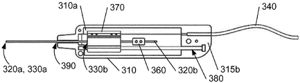
이제 도 3을 참조하면, 임플란트 장치(300)는 핸들 또는 하우징(310)과, 핸들 또는 하우징 내에 장착되어 그 원위 단부(320a)가 핸들 또는 하우징으로부터 연장되고 근위 단부(320b)가 핸들 또는 하우징 (310)내에 위치(도 4 참조)되는 고정된 샤프트(320)를 포함한다. 중공 샤프트(330)는 핸들 또는 하우징(310) 내에 장착된 그 근위 단부(도시 생략) 및 고정된 샤프트(320)의 원위 단부(320a) 위로 연장되는 원위 단부(330a)를 갖고, 고정된 샤프트(320) 상에 장착된다. 아래에서보다 상세히 설명되는 바와 같이, 임플란트 장치를 작동 메커니즘에 연결시키는 와이어(340)가 도시되어 있다.Referring now to Figure 3, the implant device 300 includes a handle or
도 4는 핸들 또는 하우징(310)의 제 1 부분(315 a)이 제거된 임플란트 장치(300)를 도시한다. 도시된 바와 같이, 고정된 샤프트(320)의 근위 단부(320b)는 고정 요소(360)에 의해 핸들 또는 하우징(310)의 제 2 부분(315b)에 연결된다. 고정된 샤프트(320) 및 슬라이더 샤프트(380)는 핸들 또는 하우징(310)의 단부면(310a)과 맞닿는 제 1 위치와 고정 요소(360)에 접하는 제 2 위치 사이에서 활주 가능하도록 구성된 슬라이딩 요소(370)를 통과한다.Figure 4 illustrates an implant device 300 with a
중공 샤프트(330)의 근위 단부(330b)는 슬라이딩 요소(370)와 결합하고, 슬라이딩 요소(370)가 제 1 위치로부터 제 2 위치로 이동할 때 고정된 샤프트(320) 위로 미끄러지도록 구성된다.The
임플란트 장치(300)의 분해도가 도 5에 도시되어있다. 도시된 바와 같이, 핸들 또는 하우징(310)은 제 1 부분(315a) 및 제 2 부분(315b)을 포함한다. 전술한 바와 같이, 고정된 샤프트(320)는 고정 요소(360)에 의해 핸들 또는 하우징(310) 내에 장착되고, 고정 요소(360)는 핸들 또는 하우징(310)의 제 2 부분(315b)에 고정된다.An exploded view of the implant device 300 is shown in Fig. As shown, the handle or
고정된 샤프트(320)와 평행하게 슬라이더 샤프트(380)가 위치한다. 슬라이더 샤프트(380)는 슬라이딩 요소(370)가 원위 단부(385a)로부터 고정 요소(360)에 인접한 부분으로 슬라이딩할 수 있는 실질적으로 원통형인 부분(385)을 포함할 수 있다. 슬라이더 샤프트(380)의 근위 단부(385b)에는 제 2 부분(315b)의 슬롯(315c) 내에 유지되는 헤드부(385c)가 제공될 수 있다. 유사하게, 슬라이더 샤프트(380)의 원위 단부(385a)는 제 2 부분(315b)의 슬롯 (315d) 내에 위치된다. 도 5에서 별도의 슬롯으로 도시되어 있지만, 슬롯(315c, 315d)은 슬라이더 샤프트(380)의 단부(385a, 385b, 385c)를 수용하도록 제 2 부분(315b) 내에서 연장되는 단일 형상의 슬롯을 포함할 수 있다.And the
와이어(340)는 외부 가요성 중공 와이어(345a) 및 내부 강성 와이어(345b)를 포함한다. 외부 와이어(345a)는 핸들 또는 하우징(310)의 제 2 부분(315b)의 슬롯(315e)에 연결되고, 내부 와이어(345b)는 구멍(370a)을 통해 슬라이딩 요소(370)에 연결되고, 핸들 또는 하우징(310)에 대하여 그 이동을 작동하도록 구성되는 것으로, 즉 내부 와이어(345b)는 핸들 또는 하우징(310)의 근위 단부(310b)를 향해 슬라이딩 요소(370)를 이동시키도록 작동한다. 이하에서 상세히 설명되는 것처럼, 슬라이딩 요소(370)를 핸들 또는 하우징의 근위 단부(310b)쪽으로 이동시킴으로써 중공 샤프트(330)는 고정된 샤프트(320) 위로 후퇴하여 션트 또는 임플란트(200)를 눈의 후방 부분 내 제 위치에 남겨둔다.The
핸들 또는 하우징(310)의 제 1 부분(315a)이 제 2 부분(315b)에 장착 될 때, 고정 요소(360)에 부착된 고정된 샤프트(320), 슬라이딩 요소(370) 및 슬라이더 샤프트(380)는 그 내부에 유지된다. When the handle or a
핸들 또는 하우징(310)의 원위 단부(310a)는 고정된 샤프트(320)의 원위 단부(320a)가 돌출하는 연장된 구멍(390)을 갖는다. 중공 샤프트(330)의 근위 단부(330b)는 구멍(390)을 통해 삽입되고 슬라이딩 요소(370)의 일부(미도시)와 결합하도록 구성된다.The
중공 샤프트(330)는 도 7에 또한 도시된 션트 또는 임플란트(200)와 함께 도 6에 도시된다. 일 실시 예에서, 중공 샤프트(330)는 원형 내부 단면을 갖는 원형 단면을 가질 수 있다. 다른 실시 예에서, 중공 샤프트(330)는 직사각형 단면, 즉 각각의 단부에서 원호에 의해 결합된 2 개의 실질적으로 평행한 에지를 갖는 단면을 가질 수 있다. 다른 실시 예에서, 중공 샤프트(330)는 직사각형 내부 단면을 갖는 직사각형 단면을 가질 수 있다. 다른 실시 예에서, 단면은 내부 단면이 중공 샤프트(330)의 외형에 의해 한정된 단면과 다른 형상을 가질 수 있다.The
션트 또는 임플란트(200)는 근위 단부(200a)의 근방에 위치된 마커(205)를 가질 수 있어서, 실질적으로 투명한 중공 샤프트(330)를 통해 그의 위치를 볼 수 있다. 예를 들어, 두 개의 마커가 션트 또는 임플란트(200)의 근위 단부(200b)에 제공될 수 있는 것과 같이, 다른 마커가 션트 또는 임플란트 (200) 상에 제공될 수 있음을 쉽게 알 수 있을 것이다.The shunt or
전술한 바와 같이, 션트 또는 임플란트(200)는 임플란트 전에 중공 샤프트(330)의 원위 단부(330a)에 위치하며, 전술한 바와 같은 적합한 생체 적합성 재료를 포함한다. 일반적으로, 션트 또는 임플란트는 4mm 내지 7mm 길이일 수 있고, 0.4mm 내지 2mm의 직경을 가질 수 있다. 일 실시 예에서, 션트 또는 임플란트(200)는 원형 단면을 가지나 중공 샤프트(330)의 내부 단면과 일치하는 임의의 적합한 단면을 가질 수 있음을 쉽게 알 수 있다. 다른 실시 예에서, 션트는 3mm와 9mm 사이의 길이, 0.3mm와 1mm 사이의 두께 및 0.5mm와 2mm 사이의 폭을 갖는 직사각형 단면을 가질 수 있다. 바람직한 실시 예에서, 션트는 길이 5mm, 두께 0.6mm 및 폭 0.1mm이다. 다른 실시 예에서, 션트는 직사각형 단면을 갖는 션트의 것과 유사한 치수를 갖는 타원형 단면을 가질 수 있다.As described above, the shunt or
도 8a 및 도 8b는 션트 또는 임플란트(200)에 대해 도시된 것에 대한 두 개의 다른 구성을 도시한다. 도 8a에서, 션트 또는 임플란트(200A)는 그것의 근위 단부(200a')에서 마커(205')를 구비하고 그 원위 단부(200b')에서 벌어져 있으며; 도 8b에서, 션트 또는 임플란트(200B)는 그의 원위 단부(200b") 및 그 근위 단부(200a") 모두에서 그 사이의 "허리부"(200c")를 구비하고 벌어진다. 전술한 바와 같이, 마커(205")는 그 근위 단부(200a")에 제공된다.Figures 8A and 8B show two different configurations for what is shown for a shunt or
일 실시 예에서, 이식 장치(300)는 살균 포장이 제거될 때 사용할 준비가 된 살균 유닛으로, 즉 핸들 또는 하우징(310) (도 3 내지 도 5를 참조하여 상술한 바와 같은 내부 구성 요소들과 함께), 고정된 샤프트(320) 및 원위 단부(330a) 내부에 션트 또는 임플란트(200)를 포함하는 중공 샤프트(330)가 제공된다.In one embodiment, the implant device 300 is a sterilizing unit ready for use when the sterilizing package is removed, i.e., a handle or housing 310 (internal components as described above with reference to FIGS. 3-5, A
조립될 때, 슬라이딩 요소(370)로부터 연장되는 고정된 샤프트(320)의 부분은 적어도 션트 또는 임플란트(200)의 길이만큼 슬라이딩 요소(370)로부터 연장되는 중공 샤프트(330)의 부분보다 짧다. 이는 션트 또는 임플란트(200)가 임플란트 형태의 원위 단부(320a)에서 고정된 샤프트(320)의 단부에 대해 중공 샤프트(330)의 원위 단부(330a)에 위치한다는 것을 의미한다.The portion of the fixed
도시되지는 않았지만, 슬라이딩 요소(370)는 슬라이딩 요소(370)와 고정 요소(360) 사이의 고정된 샤프트(320) 상에 위치된 탄성 요소에 의해 제 1 위치로 편향될 수 있고, 제 2 위치로의 이동은 안구내 션트 또는 임플란트 의 해제 동안 고정된 샤프트(320) 위로 중공 샤프트(330)의 부드러운 움직임을 보장하기 위해 탄성요소의 작용에 대항한다. 탄성 요소는 슬라이딩 요소(370)의 적절한 바이어싱을 제공하기 위해 핸들 또는 하우징 내의 임의의 다른 적절한 위치에 배치될 수 있음을 알 것이다. 탄성 요소는 압축 스프링 또는 슬라이딩 요소(370)가 핸들 또는 하우징 내의 제 1 위치로부터 제 2 위치로 이동할 때 변형 가능한 다른 적절한 탄성 요소일 수 있다.Although not shown, the sliding
도 9는 내부 이식 방법을 사용하는 안구내 션트 또는 임플란트(200)의 이식을 도시한다. 도시된 바와 같이, 션트 또는 임플란트(200)는 고정된 샤프트(320) 상에 장착된 중공 샤프트(330) 내에 유지되며, 중공 샤프트(330) 및 고정된 샤프트(320)의 전체 길이는 명확하게 도시되지 않았다. 이 실시 예에서, 중공 샤프트(330)는 그 원위 단부(330a)에서 경사팁(335)을 가지며, 경사팁은 각막(110)을 통한 중공 샤프트의 관통을 용이하게 하는데 사용된다. 그 다음 중공 샤프트(330)느 눈의 전방(160)을 가로 질러 홍채각막각 (240) 및 서브공막 공간(210)으로 향한다. 도시된 바와 같이 중공 샤프트(330)의 원위 단부(330a)에 있는 경사팁(335)은 또한 도시된 바와 같이 서브공막 공간으로 부드러운 관통을 제공하도록 구성된다.Figure 9 illustrates implantation of an intraocular shunt or
중공 샤프트(330)의 원위 단부(330a)는 각막에 절개를 제공할 필요가 없으며, 이는 중공 샤프트가 절개부 내로 삽입되는 별도의 공구에 의해 수행 될 수 있다는 것을 쉽게 알 수 있을 것이다.It will be readily seen that the
도 10은 도 9와 유사하나, 서브공막 공간(210) 내의 위치에 있는 안구내 션트 또는 임플란트(200)를 도시한다. 중공 샤프트(330)는 고정된 샤프트(320)에 대해 수축된 것으로 도시되어 있다. 안내 위치가 정확히 정해진 후에 안구내 션트 또는 임플란트(200)가 서브공막 공간 내에 배치되는 동안, 슬라이딩 요소(370)는 핸들 또는 하우징 (310) 내에서 원위 단부(310a)로부터 고정 요소(360)를 향해 이동된다. 이러한 이동은 슬라이딩 요소(370)에 연결된 중공 샤프트(330)가 고정된 샤프트(320) 위로 후퇴하여 션트 또는 임플란트(200)가 서브공막 공간 내에 위치되도록 한다.Fig. 10 shows an intraocular shunt or
가장 간단한 실시 예에서, 슬라이딩 요소(370)의 일부분은 핸들 또는 하우징(310)의 부분(315a)을 통해 연장될 수 있고, 제 1 위치로부터 제 2 위치로 눈에 션트 또는 임플란트(200)를 이식하는 의료 종사자에 의해 수동으로 움직이도록 구성된다. 그러나, 다른 실시 예에서, 슬라이딩 요소(370)는 핸들 또는 하우징(310)에 위치되고 이하에서보다 상세히 설명되는 바와 같이 작동 메커니즘을 사용하여 작동되도록 구성된다. 션트 또는 임플란트(200)가 홍체각막각(240)으로부터 임플란트 장치(300)의 중공 샤프트(330)를 인출하는 동안 이동되거나 손상되지 않도록 그리고 그자체로 눈에 손상이 입지 않도록 중공 샤프트(330)의 부드럽고 제어된 후퇴를 갖는 것이 중요하다.In the simplest embodiment, a portion of the sliding
도 11은 임플란트 장치가 눈으로부터 제거된 위치에 있는 션트 또는 임플란트(200)를 도시한다. 도시된 바와 같이, 대부분의 션트 또는 임플란트(200)는 그것의 근위 단부(200a)가 전방 챔버(160)에 있는 서브공막 공간(210)에 위치된다. 방수는 전방 챔버(160)에서 맥락막 상공간으로 흐르고, 따라서 눈의 안압을 감소시킨다. 도 3 내지 도 5를 참조하여 상술한 바와 같이, 임플란트 장치(300)는 또한 외부 가요성 중공 와이어(345a) 및 내부 강성 와이어(345b)를 포함하는 와이어(340)를 포함한다. 도 12 내지 도 14는 와이어(340)를 통해 작동 메커니즘(400)에 대한 임플란트 장치(300)의 연결을 도시한다.Figure 11 shows a shunt or
작동 메커니즘(400)은 플런저(420)가 장착되는 핸들(410)을 포함하고, 작동 메커니즘은 와이어(340)를 통해 핸들(410)에 연결된다. 외부 와이어(345a)는 작동 메커니즘(400)의 슬롯(410a)에 연결되고 내부 와이어(345b)는 플런저(420)의 일부(430)에 연결된다. 플런저(420)의 하강, 즉 핸들(410)을 향한 플런저(420)의 이동은 내부 와이어(345b)가 임플란트 장치(300)의 핸들(310)로부터 인출되어 슬라이딩 요소(370)를 제 1 위치로부터 제 2 위치로 이동시키고, 중공 샤프트(330)를 고정된 샤프트(320) 상에서 후퇴시킨다. 플런저(420)의 조기 누름을 방지하기 위해, 플런저가 제거될 때까지 플런저의 이동을 방지하기 위한 정지 요소(440) (도 12)가 제공된다.The
도 15에는 하우징 또는 핸들(410)과 유사한 하우징 또는 핸들을 포함하는 공압식 작동 메커니즘(500)이 도시되어 있다. 하우징은 피스톤(일반적으로 520으로 도시됨)이 장착되는 제 1 부분(515a) 및 제 2 부분(515b)을 포함한다. 플런저(530)는 피스톤(520)에 연결되고, 플런저(530)가 눌려지면, 피스톤이 작동되고 내부 와이어(345b)가 임플란트 장치(300)의 핸들(310)에서 빠져 나와 상술한 바와 같이 중공 샤프트(330)를 고정된 샤프트(320) 상에서 후퇴시킨다. 정지 요소(440)는 또한 도 12를 참조하여 전술한 바와 같이 도시되고 동작한다.FIG. 15 illustrates a
작동 메커니즘의 부드럽고 제어된 작동이 바람직하고, 작동 메커니즘의 플런저가 공기압으로 원활하게 제어되고 그 제어된 작동이 보장될 수 있다는 것을 쉽게 이해할 수 있을 것이다. 대안으로서, 작동 메커니즘의 플런저는 부드러운 이동 및/또는 병진 속도 제어를 위해 O-링 또는 스프링(미도시)을 포함하는 제어된 마찰 시스템의 일부를 형성할 수 있다.It will be readily appreciated that a smooth and controlled actuation of the actuation mechanism is preferred and that the plunger of the actuation mechanism can be smoothly controlled to pneumatically and its controlled actuation can be ensured. Alternatively, the plunger of the actuation mechanism may form part of a controlled friction system including an O-ring or spring (not shown) for smooth movement and / or translation speed control.
도 16은 핸들 또는 하우징(610) 및 핸들 또는 하우징(610) 내에 장착 된 고정된 샤프트(620)를 포함하는 임플란트 장치(600)의 다른 실시예를 도시한다. 도시된 바와 같이, 핸들 또는 하우징(610)은 원위 단부(610a) 및 근위 단부(610b)를 갖는다.16 illustrates another embodiment of an
장치(600)는 또한 원터치 피팅 연결 요소(OTFC)(635)에 부착된 중공 샤프트(630)를 포함하는 중공 샤프트 조립체를 포함한다. OTFC(635)가 핸들 또는 하우징(610)의 원위 단부(610a) 내에 장착될 때, 고정된 샤프트(620)가 중공 샤프트(630)를 통해 통과할 수 있도록 OTFC(635)는 중공이다.The
OTFC(635)의 원위 단부(635a)는 중공 샤프트(630)를 유지하고, OTFC(630)의 근위 단부(635b)는 핸들(610)의 원위 단부에 형성된 연장된 구멍(690)에 삽입될 때 (도 19를 참조하여 더 상세히 설명되는 바와 같이) 슬라이딩 요소(610) 내에 탑재되도록 구성된다.The
제거 가능한 커버(695)는 OTFC(635)의 원위 단부(635a) 위 및 중공 샤프트(630) 위에 제공된다. 커버(695)는 OTFC(635)가 핸들(610) 내로 삽입될 때 중공 샤프트(630) 및 중공 샤프트(630)의 원위 단부(630a) 내에 위치한 션트 또는 임플란트(도시되지 않음)를 보호하기 위한 것이다. 제거 가능한 커버(695)는 선택적이며, 근위 단부 중공 샤프트(630b)가 핸들 또는 하우징(610)의 슬라이딩 요소(670)에 결합된 후 및 중공 샤프트(630)의 원위 단부(630a)가 션트 또는 임플란트를 이식하는 동안의 눈으로 도입되기 전에 OTFC(635)로부터 제거되어져야만 한다.A
이제 도 17을 참조하면, OTFC(635)와 슬라이딩 요소(670) 사이의 상호 연결을 나타내기 위해 핸들(610)의 제 1 부분(도시되지 않음)이 제거된 임플란트 장치(600)가 도시된다. 고정된 샤프트(620)의 근위 단부(620a)는 고정 요소(660)에 의해 핸들 또는 하우징(610)의 제 2 부분(615b)에 연결된다. 고정된 샤프트(620) 및 슬라이더 샤프트(680)는 핸들 또는 하우징(610)의 단 부면(610a)과 맞닿는 제 1 위치와 고정 요소(660)에 접하는 제 2 위치 사이에서 활주 가능하도록 구성된 슬라이딩 요소(670)를 통과한다. 슬라이딩 요소(670)는 도 18을 참조하여보다 상세히 설명된다.17, there is shown an
OTFC(635)의 근위 단부(635b)는 중공 샤프트(630)를 고정된 샤프트(620) 위에 위치시키는 슬라이딩 요소(670)의 연결 요소(675)와 맞물린 다. 중공 샤프트(630)가 OTFC(635)에 고정되고 OTFC(630)의 근위 단부(635b)가 슬라이딩 요소(670)의 연결 요소(675)와 결합함에 따라 중공 샤프트(630)는 슬라이딩 요소(670)에 고정되고, 슬라이딩 요소(670)가 제 1 위치로부터 제 2 위치로 이동될 때 고정된 샤프트(620) 위로 슬라이딩되도록 구성된다.The
슬롯(615e) 및 커넥터(615f)는 외부 작동 메커니즘 (또한 도시되지 않음)으로부터 와이어 또는 연결부(도시되지 않음)를 수용하는 것으로 도시된다.
도 17에 도시된 바와 같이, 고정된 샤프트(620)는 고정 요소(660)에 의해 핸들 또는 하우징(610) 내에 장착되고, 고정 요소(660)는 핸들 또는 하우징(610)의 제 2 부분(615b)에 고정된다. 고정된 샤프트(620)와 평행하게 슬롯(615c) 내에 슬라이더 샤프트(680)가 위치된다. 슬라이더 샤프트(680)는 실질적으로 원통형인 부분(685)을 포함할 수 있으며, 슬라이딩 요소(670)는 그 원위 단부(도시되지 않음)로부터 고정 요소(660)에 인접한 부분으로 미끄러질 수 있다.17, the fixed
도 3 내지 도 5를 참조하여 상술한 바와 같이, 핸들 또는 하우징(610)의 근위 단부(610b)를 향해 슬라이딩 요소(670)를 이동시킴으로써, 중공 샤프트(630)는 고정된 샤프트(620) 위로 후퇴하여 션트 또는 임플란트(200, 200A, 200B) (도 7 및 도 8)를 전술한 바와 같이 눈의 후방 부분 내 제 위치에 고정시킨다.By moving the sliding
핸들 또는 하우징(610)의 제 1 부분이 그 제 2 부분(615b) 상에 장착될 때, 고정 요소(660)에 부착된 고정된 샤프트(620), 슬라이딩 요소(670) 및 슬라이더 샤프트(680)는 그 내부에 보유된다.The fixed
핸들 또는 하우징(610)의 원위 단부(610a)는 고정된 샤프트(620)의 원위 단부가 돌출하는 긴 구멍(690)(미도시)을 내부에 형성한다. OTFC(635)의 근위 단부(635b)는 구멍(690)을 통해 삽입되고 슬라이딩 요소(670)의 연결 요소(675)와 결합하도록 구성된다. 슬라이딩 요소(670)의 작동은 상기 도 3 내지 도 5 및 도 13 내지 도 15와 관련하여 전술한 바와 같다.The
도 16 및 도 17에 명확하게 도시되지는 않았지만, OTFC(630)는 OTFC(635)가 핸들 또는 하우징(610)에 삽입될 때, 정확한 방향을 제공하기 위해 제공된 평평한 표면을 갖는 일반적으로 둥근 몸체 부분(635g)을 갖는다는 것을 쉽게 알 수 있다. 또한, 중공 샤프트(630)가 몸체 부분(635g)을 통해 연장되고 OTFC(735)의 근위 단부(735b)에서 실질적으로 종결됨으로써 전술한 바와 같이 고정된 샤프트(620)가 그 내부에 삽입될 수 있음을 쉽게 이해할 것이다.16 and 17, the
도 18은 슬라이딩 요소(670)를 보다 상세히 도시한다. 슬라이딩 요소(670)는 원위 단부(670d) 및 근위 단부(670e)를 갖는 몸체 부분(670c)을 포함한다. 전술한 바와 같이, 슬라이딩 요소(670)는 (도 16에 도시된 바와 같이) 핸들 또는 하우징(610)의 연장된 구멍(690) 내로 그리고 통과하여 연장된 고정된 샤프트(630)가 (도 18에 도시되지 않았지만 슬라이딩 요소(370)에 대해 도 5에 도시된 것과 유사하게) 종 방향 연장 구멍을 가진다. 또 다른 종 방향 연장 구멍(도 18에는 도시되지 않지만 슬라이딩 요소 (370)에 대해 도 5에 도시된 것과 유사 함)은 슬라이딩 요소(670)가 슬라이더 샤프트(680) 상에 장착될 수 있게 한다. 도 3 내지 도 5를 참조하여 전술한 바와 같이 제어 와이어에 연결하기 위한 연결부(도시되지 않음)가 또한 근위 단부(670e)에 제공될 수 있다.18 shows the sliding
슬라이딩 요소(670)는 도시된 바와 같이 근위 단부(670e) 근처에서부터 원위 단부(670d)를 향해 연장된 후 각 연결 요소(675f, 675g) 내로 연장되는 길이를 따라 형성된 부분(670f) (도 18에서 단지 하나의 부분만 볼 수 있다)을 갖는다. 연결 요소(675f, 675g)는 OTFC(635) 상에 제공된 각각의 맞물림면(635j, 635k) (도 16 참조)과 결합하기 위한 편평한 맞물림면(675j, 675k)을 제공하는 각각의 단부 부분(675h, 675i)을 포함한다.The sliding
OTFC(635)가 슬라이딩 요소(670)의 원위 단부(670d)를 통해 연장되는 고정된 샤프트(630) 위로 핸들 또는 하우징(610) 내로 삽입될 때, OTFC(635)의 근위 단부(635b)가 OTFC(635)의 맞물림면(635j, 635k)이 단부의 각각의 맞물림면(675j, 675k)과 결합할 때까지 단부(675h, 675i)를 이격시키기 위해 단부(675h, 675i)의 경사면(675l, 675m)과 맞물리는 단부면(635d)을 구비하는 연결부(도 19 및 도 20을 참조하여보다 상세하게 설명됨)를 형성되도록 단부(675h, 675i)는 내측으로 튀어 나온다. 일단 각각의 맞물림면이 결합되면, OTFC(635)는 핸들 또는 하우징(610) 내에 장착된 슬라이딩 요소(670) 내에 견고하게 유지된다.When the
단지 두 개의 단부(675h, 675i)가 도 18을 참조하여 기술되었지만, OTFC(635)의 근위 단부(635b)와의 확실한 맞물림을 제공하도록 임의의 적절한 수의 단부가 구현될 수 있음을 쉽게 알 수 있다.Although only two
또한 원터치 고정 연결은 중공 샤프트에 부착된 임의의 다른 적절한 고정 연결 요소로 대체될 수 있음을 쉽게 알 수 있을 것이다. It will also be readily appreciated that the one-touch fixed connection may be replaced by any other suitable fixed connection element attached to the hollow shaft.
이제 도 19를 참조하면, 원위 단부(735a)에서 중공 샤프트(730)에 연결된 OTFC(735)를 포함하는 중공 샤프트 (또는 OTFC) 조립체가 도시되어 있다. 제거 가능한 커버(도시되지 않음)는 사용 전에 중공 샤프트(730)에 제공될 수 있다. OTFC(735)는 도 18을 참조하여 전술한 슬라이딩 요소(670)에 연결되도록 구성된 근위 단부(735b)에 연결부(735d)를 갖는 몸체 부분(735c)을 갖는다. 연결부(735d)는 도 18을 참조하여 전술한 바와 같이 슬라이딩 요소(670)의 경사면(675l, 675m)과 맞물리는 경사면(735l, 735m)을 갖는 단부면(735e)을 포함한다.Referring now to FIG. 19, a hollow shaft (or OTFC) assembly is shown that includes an
또한, 상기한 바와 같이 슬라이딩 요소(670)의 각 맞물림면(675j, 675k)과 결합하는 맞물림면(735j, 735k)을 형성하는 연결부(735d)에 인접하여 오목부(735f)가 제공된다. 일단 단부(675h, 675i)가 경사면(735l, 735m)을 따라 단면(735l, 735m)을 지나 오목부(735f)를 지나면, 맞물림면(735j, 735k)은 중공 샤프트 또는 OTFC 조립체를 유지하기 위해 슬라이딩 요소(670)의 각 맞물림면 (675j, 675k)을 고정된 샤프트(620) 위에 위치된 중공 샤프트(730)와 함께 핸들 또는 하우징(610) 내의 제 위치에 고정시킨다 (도 16 및 도 17에 관해서 상술).The
OTFC(735)의 몸체 부분(735c)은 내부에 형성된 평평한 표면(735h)을 갖는 대체로 둥근 몸체 부분(735g)을 포함한다. 평평한 표면(735h)은 핸들 또는 하우징(610) 내에 위치한 슬라이딩 요소(670) 내로 근위 단부(735b)를 삽입하기 위한 올바른 방향에 대한 지시를 사용자에게 제공한다.The
도 19에 도시된 실시 예에서, 중공 샤프트(730)는 원위 단부(730a) 근처에 경사팁(730d)을 구비한 만곡부(730c)를 구비한다. 사용시, 경사팁(730d)은 경사면이 상방을 향하도록 배향되어진다. 경사팁(730d)의 상방 배향은 중공 샤프트 또는 OTFC 조립체가 핸들 또는 하우징(610) 내로 정확하게 삽입될 수 있도록 OTFC(735)의 평평한 표면(735h)과 정렬된다. 전술한 바와 같이, 션트 또는 임플란트(도시되지 않음)는 중공 샤프트(730)의 원위 단부(730a)에 위치되지만, 중공 샤프트(730) 내에 완전히 위치하도록 경사팁(730d)으로부터 후방에 위치한다.In the embodiment shown in Figure 19, the
도 19에 도시되지는 않았지만, 중공 샤프트(730)가 몸체 부분(735g)을 통해 연장되고 OTFC(735)의 근위 단부에서 실질적으로 종결됨으로써 고정된 샤프트(620) (도 16 및 도 17)가 그 내부에 삽입될 수 있음을 쉽게 이해할 것이다. 상술한 바와 같이, 또한, 중공 샤프트(730)는 원위 단부(730a) (또한 도시되지 않음)에 션트 또는 임플란트를 보유하도록 구성된다.Although not shown in FIG. 19, the
도 20은 원위 단부(835a)에서 중공 샤프트(830)에 연결된 OTFC(835)를 포함하는 다른 중공 샤프트 또는 OTFC 어셈블리를 도시한다. 제거 가능한 커버(도시되지 않음)는 사용 전에 중공 샤프트(830)에 제공될 수 있다. OTFC(835)는 도 18을 참조하여 전술한 슬라이딩 요소(670)에 연결되도록 구성된 근위 단부(835b)에 연결부(835d)를 갖는 몸체 부분(835c)을 갖는다. 연결부(835d)는 도 18을 참조하여 전술한 바와 같이 슬라이딩 요소(670)의 경사면(675l, 675m)과 맞물리는 경사면 (835l, 835m)을 갖는 단 부면(835e)을 포함한다.20 shows another hollow shaft or OTFC assembly including an
또한, 전술한 바와 같이 슬라이딩 요소(670)의 각각의 맞물림면(675j, 675k)과 결합하는 맞물림면(835j, 835k)을 형성하는 연결부(835d)에 인접하여 오목부(835f)가 제공된다. 일단 단부(675h, 675i)가 경사면(835l, 835m)을 따라 오목부(835f) 내로 단부면(835d)을 지나면, 맞물림면(835j, 835k)은 (도 16 및도 17에 대해 전술 한 바와 같이) 고정된 샤프트(620) 위에 위치된 중공 샤프트(830)를 구비하는 핸들 또는 하우징 (610) 내의 제 위치에 중공 샤프트 또는 OTFC 조립체를 유지하기 위해 슬라이딩 부재(670)의 각 맞물림면(675j, 675k)과 결합된다. OTFC(835)의 몸체 부분(835c)은 내부에 형성된 평평한 표면(835h)을 갖는 일반적으로 둥근 몸체 부분(835g)을 포함한다. 평평한 표면(835h)은 핸들 또는 하우징(610) 내에 위치한 슬라이딩 요소(670) 내로 근위 단부(835b)를 삽입하기 위한 올바른 방향에 대한 지시를 사용자에게 제공한다.Also provided is a
도 20에 도시된 실시 예에서, 중공 샤프트(830)는 원위 단부(830a)에서 경사팁(830d)을 갖는 실질적으로 직선형이다. 사용시, 경사팁(830d)은 경사가 상방을 향하도록 배향되어야한다. 경사팁(830d)의 상방 배향은 OTFC(835)의 평평한 표면(835h)과 정렬되어 중공 샤프트 또는 OTFC 조립체가 핸들 또는 하우징(610) 내로 정확하게 삽입될 수 있게 한다. 전술한 바와 같이, 션트 또는 임플란트(도시되지 않음)는 중공 샤프트(830)의 원위 단부(830a) 내에 위치하여 중공 샤프트(830) 내에 완전히 위치한다.In the embodiment shown in Fig. 20, the
도 20에 도시되지는 않았지만, 중공 샤프트(830)가 몸체 부분(835g)을 통해 연장되고 OTFC(835)의 근위 단부에서 실질적으로 종결됨으로써 상술한 바와 같이, 고정된 샤프트(620) (도 16 및 도 17)가 그 내부에 삽입될 수 있음을 쉽게 이해할 것이다.Although not shown in FIG. 20, the
또 다른 실시 예에서, 중공 샤프트의 팁은 가요성이고 홍채각막각에서 공막 곡률과 일치하여 션트 또는 임플란트가 IOP를 감소시키는 배수 경로를 제공하기 위한 전방 챔버 내로 연장되는 부분을 갖는 맥락막 공간 내의 공막 박리와 섬모체 사이에 위치되도록 한다.In another embodiment, the tip of the hollow shaft is flexible and has a scleral or an implant coinciding with the scleral curvature at the iris corneal angle so that the scleral flap in the choroidal space having a portion extending into the front chamber to provide a drain path to reduce IOP And the island mother body.
상기 도 16 내지 도 20을 참조하여 기술된 실시 예에서, 사용자 (일반적으로 외과 의사)에게는 원위 단부(610a)에서 연장된 구멍(690)을 통해 연장되는 고정된 샤프트(620)를 갖는 핸들(610)(도 16)이 제공된다. 핸들(610)은 바람직하게는 살균 패키지로 제공된다. 또한, 사용자는 중공 샤프트 또는 OTFC 어셈블리(도 16, 도 19 및 도 20을 참조하여 설명됨)를 구비한다. 중공 샤프트 또는 OTFC 어셈블리는 또한 보관 중에 션트 또는 임플란트가 건조되는 것을 방지하기 위해 식염수를 함유할 수 있는 살균 패키지(제거 가능한 커버가 있거나 없음)로 제공된다. 두 개의 살균 패키지가 개방되면, OTFC의 근위 단부는 핸들 또는 하우징(610) 내의 슬라이딩 요소(670)와 연결될 때까지, 중공 샤프트 또는 OTFC 조립체는 중공 샤프트 또는 OTFC 조립체를 구멍(690)에 삽입하기 전에 OTFC 본체의 평평한 표면을 핸들(610)과 정확하게 정렬시킴으로써 핸들 또는 하우징(610)에 장착된다. 핸들 또는 하우징(610)은 또한 액츄에이터에 연결되고 시스템은 사용 준비가 완료된다. 상기 시스템은 중공 샤프트 또는 OTFC 조립체가 핸들 또는 하우징에 이미 장착된 단일 품목, 즉 단일 패키지로 공급될 수 있음을 쉽게 알 수 있을 것이다. 이 경우, 단일 패키지는 멸균될 것이며, 전술한 바와 같이 제거 가능한 커버를 포함할 수도 있고 포함하지 않을 수도 있다.16-20, a user (typically a surgeon) is provided with a
사용 후, 중공 샤프트 또는 OTFC 어셈블리(이제 션트 또는 임플란트가 없음)와 함께 핸들이 액추에이터에서 분리되어 시스템의 이러한 요소가 일회용이므로 폐기된다. 액추에이터는 살균 후에 재사용되거나 폐기될 수 있다. 그러나, 중공 샤프트 또는 OTFC 어셈블리가 분리되면 적절한 멸균 후에 핸들을 재사용할 수 있음을 쉽게 알 수 있다.After use, the handle is disengaged from the actuator with a hollow shaft or OTFC assembly (no shunt or implant now) and these elements of the system are disposable and discarded. The actuator may be reused or discarded after sterilization. However, it can be easily seen that if the hollow shaft or OTFC assembly is detached, the handle can be reused after proper sterilization.
대안으로서 또는 추가로서, 중공 샤프트 또는 OTFC 어셈블리가 사용 전에 핸들 또는 하우징(610)에 정확하게 삽입되는 것을 보장하기 위해 다른 유형의 코딩이 OTFC 상에 제공될 수 있다.Alternatively or additionally, other types of coding may be provided on the OTFC to ensure that the hollow shaft or OTFC assembly is correctly inserted into the handle or
전술한 실시 예들 각각에서, 중공 샤프트는 그것이 삽입되고 통과하는 조직에 대한 외상을 최소화하는 비외상성팁을 포함한다.In each of the foregoing embodiments, the hollow shaft includes a non-traumatic tip that minimizes trauma to the tissue through which it is inserted and through.
전술한 바와 같이, 슬라이딩 요소는 와이어에 의해 핸들 또는 하우징에 연결된 작동 메커니즘에 의해 작동된다. 그러나, 슬라이더를 조작하는 다른 방법이 가능할 수도 있음을 쉽게 알 수 있을 것이다. 예를 들어, 액추에이터와 핸들 또는 하우징 사이에 무선 링크가 제공될 수 있으며, 그 위에 적절한 제어 신호가 서보-메커니즘에 보내져, 맥락막 상공간이 의도된 임플란트 부위인 경우 서보 메커니즘은 중공 샤프트와 함께 슬라이딩 요소를 수축시켜 전방 챔버와 맥락막 상공간 사이 위치에 션트 또는 임플란트를 남긴다.As described above, the sliding element is actuated by an actuating mechanism connected to the handle or housing by a wire. However, it will be readily appreciated that other methods of manipulating the slider may be possible. For example, a wireless link may be provided between the actuator and the handle or housing upon which a suitable control signal is sent to the servo-mechanism so that when the choroidal space is the intended implant site, the servo mechanism is coupled to the sliding element To leave a shunt or implant at a location between the anterior chamber and choroidal space.
본 발명은 맥락막 상공간으로 션트 또는 임플란트를 이식하기 위한 장치 또는 시스템에 대해 설명되었지만, 다른 결막 부위, 예를 들어 결막 아래 공간 및 공막 내 공간도 가능하다. 이상적으로는, 중공 샤프트는 임플란트가 위치될 안구 조직의 만곡부와 일치하도록 가요성이 있도록 구성된다.Although the present invention has been described with respect to an apparatus or system for implanting a shunt or implant into the choroidal space, other conjunctival regions, such as subconjunctival space and intrathecal space, are also possible. Ideally, the hollow shaft is configured to be flexible to match the curvature of the eye tissue where the implant will be located.
본 발명은 전술한 실시 예들에 한정되지 않으며 대안들이 가능하다는 것을 쉽게 이해할 것이다.It will be readily understood that the invention is not limited to the embodiments described above and that alternatives are possible.
100 눈
110 각막
120 홍채
130 동공
140 수정체
150 섬모체
160 전방 챔버
170 다공성 섬유질 망
190 공막
195 맥락막
200 임플란트
210 서브공막 영역
240 홍채각막각
300 임플란트 장치
301 하우징
320 고정된 샤프트
320a 원위 단부
320b 근위 단부
330 중공 샤프트
335 경사팁
340 와이어
360 고정 요소
370 슬라이딩 요소
380 슬라이더 샤프트
390 구멍
400 작동 메커니즘
410 핸들
420 플런저
440 정지 요소
600 임플란트 장치
635 원터치 피팅 연결 요소100 eyes
110 cornea
120 iris
130 Pupil
140 lens
150 island matrix
160 front chamber
170 Porous fiber mesh
190 Sclera
195 Chorus
200 Implant
210 subscore area
240 iris corneal angle
300 Implant device
301 Housing
320 Fixed shaft
320a distal end
320b proximal end
330 hollow shaft
335 Sloped tip
340 wire
360 fixed elements
370 Sliding element
380 slider shaft
390 hole
400 operating mechanism
410 Handle
420 plunger
440 Stopping element
600 Implant Device
635 One-touch fitting connection element
Claims (36)
하우징;
상기 하우징 내에 장착되고 그에 고정되는 근위 단부 및 상기 하우징으로부터 연장된 원위 단부를 구비하는 고정된 샤프트;
상기 고정된 샤프트 상에 그리고 적어도 부분적으로는 상기 하우징 내에 장착되고, 상기 하우징 및 적어도 상기 고정된 샤프트에 대해 제 1 위치와 제 2 위치 사이에서 이동되도록 구성된 슬라이딩 요소를 포함하는 전달 메카니즘; 및
원위 단부 및 근위 단부를 가지며 상기 고정된 샤프트의 원위 단부 위에 장착되고 상기 근위 단부에서 상기 슬라이딩 요소에 연결되도록 구성되고, 상기 원위 단부에서 일부분 내에 임플란트를 보유하고, 상기 원위 단부 내에서 상기 임플란트를 해제하기 위해 상기 제 1 위치로부터 상기 제 2 위치로 상기 슬라이딩 요소의 이동에 의해 상기 고정된 샤프트 상으로 후퇴되도록 구성되는 중공 샤프트;를 포함하고,
상기 전달 메커니즘은 상기 하우징 내에 장착되고 상기 고정된 샤프트에 평행하게 구성된 슬라이더 샤프트를 더 포함하고, 상기 슬라이딩 요소는 상기 슬라이더 샤프트 및 상기 고정된 샤프트 모두에 장착되는 것을 특징으로 하는 임플란트 장치.An implant device for implanting implants into a posterior space of an eye,
housing;
A fixed shaft having a proximal end mounted in and fixed to the housing and a distal end extending from the housing;
A transfer mechanism mounted on the fixed shaft and at least partially within the housing and configured to be moved between a first position and a second position relative to the housing and at least the fixed shaft; And
The implant having a distal end and a proximal end, the distal end being mounted on a distal end of the fixed shaft and connected to the sliding element at the proximal end, the implant having a distal end within the distal end, The first shaft being configured to be retracted onto the fixed shaft by movement of the sliding element from the first position to the second position,
Wherein the delivery mechanism further comprises a slider shaft mounted in the housing and configured to be parallel to the fixed shaft, wherein the sliding element is mounted to both the slider shaft and the fixed shaft.
상기 눈의 후방 공간에 이식되도록 구성된 임플란트; 및
제 1 항 내지 제 17 항 중 어느 한 항에 따른 임플란트 장치를 포함하고, 상기 임플란트는 상기 중공 샤프트의 원위 단부에 위치되는 것을 특징으로 하는 안구 임플란트 시스템.An eye implant system configured to implant implants in a rear space of an eye,
An implant configured to be implanted in a rear space of the eye; And
18. An ocular implant system, comprising an implant device according to any one of claims 1 to 17, wherein the implant is located at a distal end of the hollow shaft.
근위 단부 및 원위 단부를 구비하고, 상기 근위 단부는 상기 하우징 내부에 장착되고 상기 하우징에 대해 고정되고, 상기 원위 단부는 상기 하우징으로부터 연장하는 고정된 샤프트; 및
상기 고정된 샤프트 상에 그리고 적어도 부분적으로는 상기 하우징 내에 장착되고, 상기 하우징 및 적어도 상기 고정된 샤프트에 대해 제 1 위치와 제 2 위치 사이에서 이동되도록 구성된 슬라이딩 요소를 포함하는 전달 메커니즘;을 포함하고,
상기 전달 메커니즘은 상기 하우징 내에 장착되고 상기 고정된 샤프트에 평행하게 구성된 슬라이더 샤프트를 더 포함하고, 상기 슬라이딩 요소는 상기 슬라이더 샤프트 및 상기 고정된 샤프트 모두에 장착되는 것을 특징으로 하는 하우징.In a housing for an implant device,
A proximal end having a proximal end and a proximal end fixedly secured to the housing, the proximal end being mounted within the housing and the distal end extending from the housing; And
And a sliding element mounted on the fixed shaft and at least partially within the housing, the sliding element being configured to move between the first position and the second position relative to the housing and at least the fixed shaft ,
Wherein the transmission mechanism further comprises a slider shaft mounted in the housing and configured parallel to the fixed shaft, wherein the sliding element is mounted to both the slider shaft and the fixed shaft.
원위 단부 및 근위 단부를 가지며 고정된 샤프트의 원위 단부 위에 장착되고, 상기 근위 단부에서 슬라이딩 요소에 연결되도록 구성되도록 구성되고, 상기 원위 단부에서 임플란트를 보유하도록 구성되며, 제 1 위치로부터 제 2 위치로 상기 슬라이딩 요소의 이동에 의해 상기 고정된 샤프트 상으로 후퇴되어 상기 임플란트를 상기 원위 단부 내에서 해제하도록 구성된 중공 샤프트;
상기 중공 샤프트의 상기 원위 단부에 위치된 상기 임플란트; 및
상기 중공 샤프트가 연결되는 고정 연결 요소;를 포함하는 것을 특징으로 하는 중공 샤프트 어셈블리.A hollow shaft assembly for an implant device,
A distal end of the implant is configured to be mounted on a distal end of the fixed shaft having a distal end and a proximal end and configured to be connected to the sliding element at the proximal end and configured to retain the implant at the distal end, A hollow shaft configured to be retracted onto the fixed shaft by movement of the sliding element to release the implant within the distal end;
The implant positioned at the distal end of the hollow shaft; And
And a fixed connection element to which the hollow shaft is connected.
제 24 항 내지 제 34 항 중 어느 한 항에 따른 중공 샤프트 어셈블리를 포함하는 안구 임플란트 키트.A housing according to claim 23; And
35. An ocular implant kit comprising a hollow shaft assembly according to any one of claims 24 to 34.
Applications Claiming Priority (3)
| Application Number | Priority Date | Filing Date | Title |
|---|---|---|---|
| EP15202724 | 2015-12-24 | ||
| EP15202724.9 | 2015-12-24 | ||
| PCT/EP2016/080763 WO2017108498A1 (en) | 2015-12-24 | 2016-12-13 | Ocular implant systems |
Publications (2)
| Publication Number | Publication Date |
|---|---|
| KR20180098303A true KR20180098303A (en) | 2018-09-03 |
| KR102431824B1 KR102431824B1 (en) | 2022-08-12 |
Family
ID=55069738
Family Applications (1)
| Application Number | Title | Priority Date | Filing Date |
|---|---|---|---|
| KR1020187020377A Active KR102431824B1 (en) | 2015-12-24 | 2016-12-13 | eye implant system |
Country Status (17)
| Country | Link |
|---|---|
| US (2) | US20190038462A1 (en) |
| EP (2) | EP4137102A1 (en) |
| JP (2) | JP2019500130A (en) |
| KR (1) | KR102431824B1 (en) |
| CN (2) | CN113558860B (en) |
| AU (2) | AU2016378890B2 (en) |
| CA (2) | CA3009544C (en) |
| DK (1) | DK3393412T3 (en) |
| ES (1) | ES2935384T3 (en) |
| FI (1) | FI3393412T3 (en) |
| HR (1) | HRP20221407T1 (en) |
| HU (1) | HUE060526T2 (en) |
| PL (1) | PL3393412T3 (en) |
| PT (1) | PT3393412T (en) |
| RS (1) | RS63739B1 (en) |
| SI (1) | SI3393412T1 (en) |
| WO (1) | WO2017108498A1 (en) |
Cited By (1)
| Publication number | Priority date | Publication date | Assignee | Title |
|---|---|---|---|---|
| WO2021101080A1 (en) * | 2019-11-19 | 2021-05-27 | 주식회사 마이크로트 | Eye disease implant device capable of lowering eye pressure by easy and safe method |
Families Citing this family (30)
| Publication number | Priority date | Publication date | Assignee | Title |
|---|---|---|---|---|
| US11166849B2 (en) | 2017-07-20 | 2021-11-09 | Shifamed Holdings, Llc | Adjustable flow glaucoma shunts and methods for making and using same |
| WO2019018807A1 (en) | 2017-07-20 | 2019-01-24 | Shifamed Holdings, Llc | Adjustable flow glaucoma shunts and methods for making and using same |
| US20210045917A1 (en) * | 2018-02-02 | 2021-02-18 | Rhb Research, Llc | Devices and Methods for Illuminating an Intraocular Implant |
| US12329682B2 (en) | 2019-01-18 | 2025-06-17 | Shifamed Holdings, Llc | Adjustable flow glaucoma shunts and methods for making and using same |
| EP3930647A4 (en) * | 2019-02-27 | 2022-11-30 | Innfocus, Inc. | INSERT DEVICE FOR GLAUCOMA DEVICE |
| CN119279913A (en) | 2019-06-14 | 2025-01-10 | 安特雷克公司 | Bracket |
| US12551268B2 (en) | 2019-07-08 | 2026-02-17 | Shifamed Holdings, Llc | Minimally invasive bleb formation devices and methods for using such devices |
| US11517477B2 (en) | 2019-10-10 | 2022-12-06 | Shifamed Holdings, Llc | Adjustable flow glaucoma shunts and associated systems and methods |
| CA3058571A1 (en) * | 2019-10-11 | 2021-04-11 | Houfar SEKHAVAT | Glaucoma shunts and related methods of use |
| WO2021127205A1 (en) * | 2019-12-17 | 2021-06-24 | Glaukos Corporation | Ocular tissue perforation device |
| WO2021151007A1 (en) | 2020-01-23 | 2021-07-29 | Shifamed Holdings, Llc | Adjustable flow glaucoma shunts and associated systems and methods |
| CN115426988A (en) | 2020-02-14 | 2022-12-02 | 施菲姆德控股有限责任公司 | Flow diversion systems having rotation-based flow control assemblies, and related systems and methods |
| EP4106695A4 (en) | 2020-02-18 | 2024-03-20 | Shifamed Holdings, LLC | Adjustable flow glaucoma shunts having non-linearly arranged flow control elements, and associated systems and methods |
| CA3173311A1 (en) * | 2020-02-27 | 2021-09-02 | Istar Medical Sa | Package for retaining and dispensing a delivery shaft assembly for delivery of an implant |
| US11766355B2 (en) | 2020-03-19 | 2023-09-26 | Shifamed Holdings, Llc | Intraocular shunts with low-profile actuation elements and associated systems and methods |
| CN111449834B (en) * | 2020-04-15 | 2022-03-01 | 贵州省人民医院 | Lacrimal passage drainage device for lacrimal duct embolism and drainage method thereof |
| JP7743435B2 (en) | 2020-04-16 | 2025-09-24 | シファメド・ホールディングス・エルエルシー | Adjustable Glaucoma Treatment Device and Associated Systems and Methods |
| JP7699150B2 (en) | 2020-05-20 | 2025-06-26 | イアンテック・インコーポレイテッド | System for forming and implanting a biological intraocular stent for increasing aqueous humor outflow and reducing intraocular pressure - Patents.com |
| US12453656B2 (en) | 2020-05-20 | 2025-10-28 | Iantrek, Inc. | System for shaping and implanting biologic intraocular stent for increased aqueous outflow and lowering of intraocular pressure |
| DE102020211175A1 (en) | 2020-09-04 | 2022-03-10 | Carl Zeiss Meditec Ag | Stent implant for glaucoma treatment by drainage of aqueous humor from the anterior chamber |
| AU2021346261A1 (en) | 2020-09-15 | 2023-02-16 | Istar Medical Sa | Delivery shaft assembly for delivery of an implant |
| WO2022058606A1 (en) | 2020-09-21 | 2022-03-24 | Carl Zeiss Meditec, Inc. | Device for positioning an implant in a target area of an eye |
| CN114272013A (en) * | 2020-09-28 | 2022-04-05 | 南昌大学第二附属医院 | Minimally invasive retinal cell transplanting device |
| WO2022159723A1 (en) | 2021-01-22 | 2022-07-28 | Shifamed Holdings, Llc | Adjustable shunting systems with plate assemblies, and associated systems and methods |
| US12440374B2 (en) | 2022-01-12 | 2025-10-14 | Innovative Drive Corporation | Mechanical hole punch for the reduction of intraocular pressure and methods of use |
| EP4489701B1 (en) | 2022-03-09 | 2025-11-26 | iSTAR Medical SA | Delivery shaft assembly for delivery of an implant |
| GB202210216D0 (en) | 2022-07-12 | 2022-08-24 | Univ Oxford Innovation Ltd | Ocular implant, kit, method of deploying |
| US20250295524A1 (en) | 2022-11-23 | 2025-09-25 | Iantrek, Inc. | Devices and systems for cutting, loading, and delivering biologic intraocular implants for increased aqueous outflow and lowering of intraocular pressure |
| CN119499038B (en) * | 2023-08-25 | 2025-10-03 | 苏州朗目医疗科技有限公司 | An eye implant |
| US12458535B1 (en) | 2025-04-25 | 2025-11-04 | Michael Reynard | Endothelial-integrated stent for Schlemm's canal and controlled aqueous humor outflow |
Citations (5)
| Publication number | Priority date | Publication date | Assignee | Title |
|---|---|---|---|---|
| US20030060752A1 (en) * | 2000-04-14 | 2003-03-27 | Olav Bergheim | Glaucoma device and methods thereof |
| US20070276315A1 (en) * | 2002-04-08 | 2007-11-29 | Glaukos Corporation | Devices and methods for glaucoma treatment |
| JP2010533565A (en) * | 2007-07-17 | 2010-10-28 | トランセンド・メディカル・インコーポレイテッド | Intraocular implant with hydrogel expansion capability |
| JP2012512725A (en) * | 2008-12-19 | 2012-06-07 | キュー エル ティー インク. | Puncture implant for substance delivery and substance delivery method |
| JP2014512240A (en) * | 2011-04-27 | 2014-05-22 | アイスター メディカル | Improvements in the management and treatment of glaucoma or in the management and treatment of glaucoma |
Family Cites Families (28)
| Publication number | Priority date | Publication date | Assignee | Title |
|---|---|---|---|---|
| FR2750055B1 (en) * | 1996-06-20 | 1998-08-07 | Braun Celsa Sa | MEDICAL ASSEMBLY OF REMOVABLE LINK BETWEEN A TUBE AND A ROD |
| US6156042A (en) * | 1997-11-17 | 2000-12-05 | Aramant; Robert B. | Retinal tissue implantation instrument |
| US20050119601A9 (en) * | 1999-04-26 | 2005-06-02 | Lynch Mary G. | Shunt device and method for treating glaucoma |
| US6464724B1 (en) | 1999-04-26 | 2002-10-15 | Gmp Vision Solutions, Inc. | Stent device and method for treating glaucoma |
| US6159218A (en) * | 1999-05-19 | 2000-12-12 | Aramant; Robert B. | Retinal tissue implantation tool |
| US20050119737A1 (en) * | 2000-01-12 | 2005-06-02 | Bene Eric A. | Ocular implant and methods for making and using same |
| US20030229303A1 (en) * | 2002-03-22 | 2003-12-11 | Haffner David S. | Expandable glaucoma implant and methods of use |
| US6899717B2 (en) * | 2002-09-18 | 2005-05-31 | Allergan, Inc. | Methods and apparatus for delivery of ocular implants |
| US20040225250A1 (en) * | 2003-05-05 | 2004-11-11 | Michael Yablonski | Internal shunt and method for treating glaucoma |
| US20040236343A1 (en) * | 2003-05-23 | 2004-11-25 | Taylor Jon B. | Insertion tool for ocular implant and method for using same |
| WO2005032418A2 (en) * | 2003-10-01 | 2005-04-14 | University Of Washington | Novel porous biomaterials |
| US7431709B2 (en) * | 2003-12-05 | 2008-10-07 | Innfocus, Llc | Glaucoma implant device |
| US8758290B2 (en) * | 2010-11-15 | 2014-06-24 | Aquesys, Inc. | Devices and methods for implanting a shunt in the suprachoroidal space |
| US8852137B2 (en) * | 2010-11-15 | 2014-10-07 | Aquesys, Inc. | Methods for implanting a soft gel shunt in the suprachoroidal space |
| WO2008061043A2 (en) * | 2006-11-10 | 2008-05-22 | Glaukos Corporation | Uveoscleral shunt and methods for implanting same |
| EP2214608B1 (en) * | 2007-11-08 | 2015-03-04 | Alimera Sciences, Inc. | Ocular implantation device |
| WO2010115101A1 (en) | 2009-04-03 | 2010-10-07 | Transcend Medical, Inc. | Ocular implant delivery systems and methods |
| WO2011084550A2 (en) * | 2009-12-16 | 2011-07-14 | Eyevation, Llc | Delivery and extraction devices |
| WO2012144980A1 (en) * | 2011-04-18 | 2012-10-26 | Johnson & Johnson Vision Care, Inc. | Implantation instruments, system, and kit for punctal implants |
| WO2012167167A2 (en) * | 2011-06-02 | 2012-12-06 | Silvestrini Thomas A | Eye shunt with porous structure |
| US8852136B2 (en) * | 2011-12-08 | 2014-10-07 | Aquesys, Inc. | Methods for placing a shunt into the intra-scleral space |
| US9808373B2 (en) * | 2013-06-28 | 2017-11-07 | Aquesys, Inc. | Intraocular shunt implantation |
| WO2013095790A2 (en) * | 2011-12-23 | 2013-06-27 | Aquesys, Inc. | Devices and methods for implanting a shunt in the suprachoroidal space |
| ES2961369T3 (en) * | 2012-03-20 | 2024-03-11 | Sight Sciences Inc | Eye delivery systems |
| EP3730103B1 (en) * | 2012-04-19 | 2024-12-04 | Alcon Inc. | Delivery system for ocular implant |
| US9241832B2 (en) * | 2012-04-24 | 2016-01-26 | Transcend Medical, Inc. | Delivery system for ocular implant |
| US9592151B2 (en) * | 2013-03-15 | 2017-03-14 | Glaukos Corporation | Systems and methods for delivering an ocular implant to the suprachoroidal space within an eye |
| EP3110375B1 (en) * | 2014-02-26 | 2022-01-26 | Allergan, Inc. | Intraocular implant delivery apparatus |
-
2016
- 2016-12-13 CN CN202110874624.6A patent/CN113558860B/en active Active
- 2016-12-13 DK DK16820191.1T patent/DK3393412T3/en active
- 2016-12-13 FI FIEP16820191.1T patent/FI3393412T3/en active
- 2016-12-13 PT PT168201911T patent/PT3393412T/en unknown
- 2016-12-13 ES ES16820191T patent/ES2935384T3/en active Active
- 2016-12-13 HR HRP20221407TT patent/HRP20221407T1/en unknown
- 2016-12-13 WO PCT/EP2016/080763 patent/WO2017108498A1/en not_active Ceased
- 2016-12-13 PL PL16820191.1T patent/PL3393412T3/en unknown
- 2016-12-13 AU AU2016378890A patent/AU2016378890B2/en active Active
- 2016-12-13 EP EP22199340.5A patent/EP4137102A1/en active Pending
- 2016-12-13 KR KR1020187020377A patent/KR102431824B1/en active Active
- 2016-12-13 CA CA3009544A patent/CA3009544C/en active Active
- 2016-12-13 CA CA3168214A patent/CA3168214A1/en active Pending
- 2016-12-13 CN CN201680076221.4A patent/CN108430404B/en active Active
- 2016-12-13 JP JP2018533607A patent/JP2019500130A/en active Pending
- 2016-12-13 SI SI201631612T patent/SI3393412T1/en unknown
- 2016-12-13 US US16/065,696 patent/US20190038462A1/en not_active Abandoned
- 2016-12-13 RS RS20221046A patent/RS63739B1/en unknown
- 2016-12-13 EP EP16820191.1A patent/EP3393412B1/en active Active
- 2016-12-13 HU HUE16820191A patent/HUE060526T2/en unknown
-
2020
- 2020-06-30 AU AU2020204391A patent/AU2020204391B2/en active Active
-
2022
- 2022-11-04 JP JP2022176981A patent/JP7497406B2/en active Active
-
2023
- 2023-04-21 US US18/305,196 patent/US20230248569A1/en active Pending
Patent Citations (5)
| Publication number | Priority date | Publication date | Assignee | Title |
|---|---|---|---|---|
| US20030060752A1 (en) * | 2000-04-14 | 2003-03-27 | Olav Bergheim | Glaucoma device and methods thereof |
| US20070276315A1 (en) * | 2002-04-08 | 2007-11-29 | Glaukos Corporation | Devices and methods for glaucoma treatment |
| JP2010533565A (en) * | 2007-07-17 | 2010-10-28 | トランセンド・メディカル・インコーポレイテッド | Intraocular implant with hydrogel expansion capability |
| JP2012512725A (en) * | 2008-12-19 | 2012-06-07 | キュー エル ティー インク. | Puncture implant for substance delivery and substance delivery method |
| JP2014512240A (en) * | 2011-04-27 | 2014-05-22 | アイスター メディカル | Improvements in the management and treatment of glaucoma or in the management and treatment of glaucoma |
Cited By (2)
| Publication number | Priority date | Publication date | Assignee | Title |
|---|---|---|---|---|
| WO2021101080A1 (en) * | 2019-11-19 | 2021-05-27 | 주식회사 마이크로트 | Eye disease implant device capable of lowering eye pressure by easy and safe method |
| US12599501B2 (en) | 2019-11-19 | 2026-04-14 | Microt Inc. | Eye disease implant device capable of lowering eye pressure by easy and safe method |
Also Published As
| Publication number | Publication date |
|---|---|
| ES2935384T3 (en) | 2023-03-06 |
| AU2020204391A1 (en) | 2020-07-23 |
| CA3168214A1 (en) | 2017-06-29 |
| CA3009544C (en) | 2022-09-27 |
| CA3009544A1 (en) | 2017-06-29 |
| SI3393412T1 (en) | 2023-01-31 |
| WO2017108498A1 (en) | 2017-06-29 |
| KR102431824B1 (en) | 2022-08-12 |
| JP2019500130A (en) | 2019-01-10 |
| US20190038462A1 (en) | 2019-02-07 |
| DK3393412T3 (en) | 2022-12-05 |
| PL3393412T3 (en) | 2023-02-06 |
| HUE060526T2 (en) | 2023-03-28 |
| EP4137102A1 (en) | 2023-02-22 |
| EP3393412A1 (en) | 2018-10-31 |
| JP7497406B2 (en) | 2024-06-10 |
| CN113558860A (en) | 2021-10-29 |
| AU2016378890B2 (en) | 2020-04-23 |
| HRP20221407T1 (en) | 2023-01-06 |
| RS63739B1 (en) | 2022-12-30 |
| PT3393412T (en) | 2022-11-15 |
| EP3393412B1 (en) | 2022-10-05 |
| CN113558860B (en) | 2026-01-13 |
| FI3393412T3 (en) | 2023-01-13 |
| US20230248569A1 (en) | 2023-08-10 |
| CN108430404A (en) | 2018-08-21 |
| CN108430404B (en) | 2021-08-24 |
| JP2023014103A (en) | 2023-01-26 |
| AU2020204391B2 (en) | 2021-12-09 |
| AU2016378890A1 (en) | 2018-07-12 |
Similar Documents
| Publication | Publication Date | Title |
|---|---|---|
| JP7497406B2 (en) | Ocular Implant System | |
| CA2870549C (en) | Delivery system for ocular implant | |
| US9301875B2 (en) | Ocular disorder treatment implants with multiple opening | |
| US9241832B2 (en) | Delivery system for ocular implant | |
| US7431710B2 (en) | Ocular implants with anchors and methods thereof | |
| EP3668460A2 (en) | Method, device, and system for treatment of elevated intraocular pressure |
Legal Events
| Date | Code | Title | Description |
|---|---|---|---|
| PA0105 | International application |
Patent event date: 20180716 Patent event code: PA01051R01D Comment text: International Patent Application |
|
| PG1501 | Laying open of application | ||
| A201 | Request for examination | ||
| PA0201 | Request for examination |
Patent event code: PA02012R01D Patent event date: 20190808 Comment text: Request for Examination of Application |
|
| E902 | Notification of reason for refusal | ||
| PE0902 | Notice of grounds for rejection |
Comment text: Notification of reason for refusal Patent event date: 20210127 Patent event code: PE09021S01D |
|
| E902 | Notification of reason for refusal | ||
| PE0902 | Notice of grounds for rejection |
Comment text: Notification of reason for refusal Patent event date: 20211125 Patent event code: PE09021S01D |
|
| E701 | Decision to grant or registration of patent right | ||
| PE0701 | Decision of registration |
Patent event code: PE07011S01D Comment text: Decision to Grant Registration Patent event date: 20220523 |
|
| GRNT | Written decision to grant | ||
| PR0701 | Registration of establishment |
Comment text: Registration of Establishment Patent event date: 20220808 Patent event code: PR07011E01D |
|
| PR1002 | Payment of registration fee |
Payment date: 20220809 End annual number: 3 Start annual number: 1 |
|
| PG1601 | Publication of registration |