KR20180098160A - Method and apparatus for processing a video signal - Google Patents
Method and apparatus for processing a video signal Download PDFInfo
- Publication number
- KR20180098160A KR20180098160A KR1020180021638A KR20180021638A KR20180098160A KR 20180098160 A KR20180098160 A KR 20180098160A KR 1020180021638 A KR1020180021638 A KR 1020180021638A KR 20180021638 A KR20180021638 A KR 20180021638A KR 20180098160 A KR20180098160 A KR 20180098160A
- Authority
- KR
- South Korea
- Prior art keywords
- block
- intra prediction
- coding
- coding block
- unit
- Prior art date
- Legal status (The legal status is an assumption and is not a legal conclusion. Google has not performed a legal analysis and makes no representation as to the accuracy of the status listed.)
- Granted
Links
- 238000000034 method Methods 0.000 title claims abstract description 109
- 238000012545 processing Methods 0.000 title description 6
- 238000001914 filtration Methods 0.000 claims description 30
- 238000003672 processing method Methods 0.000 abstract description 2
- 238000005192 partition Methods 0.000 description 244
- 238000000638 solvent extraction Methods 0.000 description 196
- 239000000523 sample Substances 0.000 description 114
- 239000013074 reference sample Substances 0.000 description 46
- 238000012937 correction Methods 0.000 description 23
- 238000013139 quantization Methods 0.000 description 20
- 238000010586 diagram Methods 0.000 description 19
- 238000006243 chemical reaction Methods 0.000 description 18
- 230000011218 segmentation Effects 0.000 description 15
- 239000013598 vector Substances 0.000 description 10
- 239000000470 constituent Substances 0.000 description 9
- 208000037170 Delayed Emergence from Anesthesia Diseases 0.000 description 6
- 230000003044 adaptive effect Effects 0.000 description 5
- 230000008569 process Effects 0.000 description 5
- 230000009466 transformation Effects 0.000 description 5
- 230000005540 biological transmission Effects 0.000 description 4
- 230000006835 compression Effects 0.000 description 4
- 238000007906 compression Methods 0.000 description 4
- 230000006870 function Effects 0.000 description 3
- 238000009499 grossing Methods 0.000 description 3
- 230000011664 signaling Effects 0.000 description 3
- 230000008859 change Effects 0.000 description 2
- 230000000694 effects Effects 0.000 description 2
- 230000014509 gene expression Effects 0.000 description 2
- 230000006872 improvement Effects 0.000 description 2
- 238000013507 mapping Methods 0.000 description 2
- 238000012986 modification Methods 0.000 description 2
- 230000004048 modification Effects 0.000 description 2
- 230000002123 temporal effect Effects 0.000 description 2
- TVEXGJYMHHTVKP-UHFFFAOYSA-N 6-oxabicyclo[3.2.1]oct-3-en-7-one Chemical compound C1C2C(=O)OC1C=CC2 TVEXGJYMHHTVKP-UHFFFAOYSA-N 0.000 description 1
- RKTYLMNFRDHKIL-UHFFFAOYSA-N copper;5,10,15,20-tetraphenylporphyrin-22,24-diide Chemical compound [Cu+2].C1=CC(C(=C2C=CC([N-]2)=C(C=2C=CC=CC=2)C=2C=CC(N=2)=C(C=2C=CC=CC=2)C2=CC=C3[N-]2)C=2C=CC=CC=2)=NC1=C3C1=CC=CC=C1 RKTYLMNFRDHKIL-UHFFFAOYSA-N 0.000 description 1
- 230000003287 optical effect Effects 0.000 description 1
- 230000001151 other effect Effects 0.000 description 1
- 230000002093 peripheral effect Effects 0.000 description 1
- 230000008707 rearrangement Effects 0.000 description 1
- 230000009467 reduction Effects 0.000 description 1
- 230000002441 reversible effect Effects 0.000 description 1
- 238000010845 search algorithm Methods 0.000 description 1
- 238000000844 transformation Methods 0.000 description 1
- 230000001131 transforming effect Effects 0.000 description 1
Images


Classifications
-
- H—ELECTRICITY
- H04—ELECTRIC COMMUNICATION TECHNIQUE
- H04N—PICTORIAL COMMUNICATION, e.g. TELEVISION
- H04N19/00—Methods or arrangements for coding, decoding, compressing or decompressing digital video signals
- H04N19/50—Methods or arrangements for coding, decoding, compressing or decompressing digital video signals using predictive coding
- H04N19/593—Methods or arrangements for coding, decoding, compressing or decompressing digital video signals using predictive coding involving spatial prediction techniques
-
- H—ELECTRICITY
- H04—ELECTRIC COMMUNICATION TECHNIQUE
- H04N—PICTORIAL COMMUNICATION, e.g. TELEVISION
- H04N19/00—Methods or arrangements for coding, decoding, compressing or decompressing digital video signals
- H04N19/10—Methods or arrangements for coding, decoding, compressing or decompressing digital video signals using adaptive coding
- H04N19/102—Methods or arrangements for coding, decoding, compressing or decompressing digital video signals using adaptive coding characterised by the element, parameter or selection affected or controlled by the adaptive coding
- H04N19/119—Adaptive subdivision aspects, e.g. subdivision of a picture into rectangular or non-rectangular coding blocks
-
- H—ELECTRICITY
- H04—ELECTRIC COMMUNICATION TECHNIQUE
- H04N—PICTORIAL COMMUNICATION, e.g. TELEVISION
- H04N19/00—Methods or arrangements for coding, decoding, compressing or decompressing digital video signals
- H04N19/10—Methods or arrangements for coding, decoding, compressing or decompressing digital video signals using adaptive coding
- H04N19/169—Methods or arrangements for coding, decoding, compressing or decompressing digital video signals using adaptive coding characterised by the coding unit, i.e. the structural portion or semantic portion of the video signal being the object or the subject of the adaptive coding
- H04N19/17—Methods or arrangements for coding, decoding, compressing or decompressing digital video signals using adaptive coding characterised by the coding unit, i.e. the structural portion or semantic portion of the video signal being the object or the subject of the adaptive coding the unit being an image region, e.g. an object
- H04N19/172—Methods or arrangements for coding, decoding, compressing or decompressing digital video signals using adaptive coding characterised by the coding unit, i.e. the structural portion or semantic portion of the video signal being the object or the subject of the adaptive coding the unit being an image region, e.g. an object the region being a picture, frame or field
-
- H—ELECTRICITY
- H04—ELECTRIC COMMUNICATION TECHNIQUE
- H04N—PICTORIAL COMMUNICATION, e.g. TELEVISION
- H04N19/00—Methods or arrangements for coding, decoding, compressing or decompressing digital video signals
- H04N19/10—Methods or arrangements for coding, decoding, compressing or decompressing digital video signals using adaptive coding
- H04N19/169—Methods or arrangements for coding, decoding, compressing or decompressing digital video signals using adaptive coding characterised by the coding unit, i.e. the structural portion or semantic portion of the video signal being the object or the subject of the adaptive coding
- H04N19/17—Methods or arrangements for coding, decoding, compressing or decompressing digital video signals using adaptive coding characterised by the coding unit, i.e. the structural portion or semantic portion of the video signal being the object or the subject of the adaptive coding the unit being an image region, e.g. an object
- H04N19/174—Methods or arrangements for coding, decoding, compressing or decompressing digital video signals using adaptive coding characterised by the coding unit, i.e. the structural portion or semantic portion of the video signal being the object or the subject of the adaptive coding the unit being an image region, e.g. an object the region being a slice, e.g. a line of blocks or a group of blocks
-
- H—ELECTRICITY
- H04—ELECTRIC COMMUNICATION TECHNIQUE
- H04N—PICTORIAL COMMUNICATION, e.g. TELEVISION
- H04N19/00—Methods or arrangements for coding, decoding, compressing or decompressing digital video signals
- H04N19/70—Methods or arrangements for coding, decoding, compressing or decompressing digital video signals characterised by syntax aspects related to video coding, e.g. related to compression standards
-
- H—ELECTRICITY
- H04—ELECTRIC COMMUNICATION TECHNIQUE
- H04N—PICTORIAL COMMUNICATION, e.g. TELEVISION
- H04N19/00—Methods or arrangements for coding, decoding, compressing or decompressing digital video signals
- H04N19/90—Methods or arrangements for coding, decoding, compressing or decompressing digital video signals using coding techniques not provided for in groups H04N19/10-H04N19/85, e.g. fractals
- H04N19/96—Tree coding, e.g. quad-tree coding
Landscapes
- Engineering & Computer Science (AREA)
- Multimedia (AREA)
- Signal Processing (AREA)
- Compression Or Coding Systems Of Tv Signals (AREA)
Abstract
본 발명은 비디오 신호 처리 방법 및 장치에 관한 것이다. 본 발명에 따른 영상 복호화 방법은,현재 코딩 블록의 방향성 인트라 예측 모드를 확인하는 단계, 현재 코딩 블록의 형태에 따라, 상기 방향성 인트라 예측 모드에 적용되는 방향성 인트라 예측 샘플 보간을 위한 보간 필터 종류를 결정하는 단계, 및 상기 결정된 보간 필터를 적용하여 인트라 예측 샘플을 생성하는 단계를 포함한다. 본 발명에 의해인트라 예측 샘플을 효율적인 보간이 가능하게 됨에 따라, 영상 신호의 부호화/복호화 효율을 증가시킬 수 있다.The present invention relates to a video signal processing method and apparatus. The method of decoding an image according to the present invention includes the steps of checking a directional intra prediction mode of a current coding block and determining an interpolation filter type for interpolation of directional intra prediction samples applied to the directional intra prediction mode, And applying the determined interpolation filter to generate an intra prediction sample. According to the present invention, it becomes possible to efficiently interpolate intraprediction samples, and thus the encoding / decoding efficiency of a video signal can be increased.
Description
본 발명은 비디오 신호 처리 방법 및 장치에 관한 것이다.The present invention relates to a video signal processing method and apparatus.
최근 HD(High Definition) 영상 및 UHD(Ultra High Definition) 영상과 같은 고해상도, 고품질의 영상에 대한 수요가 다양한 응용 분야에서 증가하고 있다. 영상 데이터가 고해상도, 고품질이 될수록 기존의 영상 데이터에 비해 상대적으로 데이터량이 증가하기 때문에 기존의 유무선 광대역 회선과 같은 매체를 이용하여 영상 데이터를 전송하거나 기존의 저장 매체를 이용해 저장하는 경우, 전송 비용과 저장 비용이 증가하게 된다. 영상 데이터가 고해상도, 고품질화 됨에 따라 발생하는 이러한 문제들을 해결하기 위해서는 고효율의 영상 압축 기술들이 활용될 수 있다.Recently, the demand for high resolution and high quality images such as high definition (HD) image and ultra high definition (UHD) image is increasing in various applications. As the image data has high resolution and high quality, the amount of data increases relative to the existing image data. Therefore, when the image data is transmitted using a medium such as a wired / wireless broadband line or stored using an existing storage medium, The storage cost is increased. High-efficiency image compression techniques can be utilized to solve such problems as image data becomes high-resolution and high-quality.
영상 압축 기술로 현재 픽쳐의 이전 또는 이후 픽쳐로부터 현재 픽쳐에 포함된 화소값을 예측하는 화면 간 예측 기술, 현재 픽쳐 내의 화소 정보를 이용하여 현재 픽쳐에 포함된 화소값을 예측하는 화면 내 예측 기술, 출현 빈도가 높은 값에 짧은 부호를 할당하고 출현 빈도가 낮은 값에 긴 부호를 할당하는 엔트로피 부호화 기술 등 다양한 기술이 존재하고 이러한 영상 압축 기술을 이용해 영상 데이터를 효과적으로 압축하여 전송 또는 저장할 수 있다.An inter picture prediction technique for predicting a pixel value included in a current picture from a previous or a subsequent picture of a current picture by an image compression technique, an intra picture prediction technique for predicting a pixel value included in a current picture using pixel information in the current picture, There are various techniques such as an entropy encoding technique in which a short code is assigned to a value having a high appearance frequency and a long code is assigned to a value having a low appearance frequency. Image data can be effectively compressed and transmitted or stored using such an image compression technique.
한편, 고해상도 영상에 대한 수요가 증가함과 함께, 새로운 영상 서비스로서 입체 영상 컨텐츠에 대한 수요도 함께 증가하고 있다. 고해상도 및 초고해상도의 입체 영상 콘텐츠를 효과적으로 제공하기 위한 비디오 압축 기술에 대하여 논의가 진행되고 있다.On the other hand, demand for high-resolution images is increasing, and demand for stereoscopic image content as a new image service is also increasing. Video compression techniques are being discussed to effectively provide high resolution and ultra-high resolution stereoscopic content.
본 발명은 영상 신호를 부호화/복호화함에 있어서, 부호화/복호화 대상 블록을 효과적으로 분할할 수 있는 멀티 트리 파티셔닝 방법 및 장치를 제공하는 것을 목적으로 한다.An object of the present invention is to provide a multitree partitioning method and apparatus capable of efficiently dividing a block to be encoded / decoded in coding / decoding a video signal.
본 발명은 영상 신호를 부호화/복호화함에 있어서, 부호화/복호화 대상 블록을 대칭 형태 또는 비대칭 형태의 블록으로 분할하는 멀티 트리 파티셔닝 방법 및 장치를 제공하는 것을 목적으로 한다.An object of the present invention is to provide a multitree partitioning method and apparatus for dividing blocks to be encoded / decoded into symmetric or asymmetric blocks in encoding / decoding a video signal.
본 발명은 멀티 트리 파티셔닝에의해 분할된 코딩 블록에 대응하는 보간된 인트라 예측 샘플을 생성하는 방법 및 장치를 제공하는 것을 목적으로 한다.It is an object of the present invention to provide a method and apparatus for generating interpolated intra prediction samples corresponding to a coded block segmented by multitree partitioning.
본 발명은 상기 부호화 방법에 의해 부호화된 영상 신호 비트스트림을포함하는 기록매체를 제공하는 것을 목적으로 한다.An object of the present invention is to provide a recording medium including a video signal bit stream encoded by the above encoding method.
본 발명에서 이루고자 하는 기술적 과제들은 이상에서 언급한 기술적 과제들로 제한되지 않으며, 언급하지 않은 또 다른 기술적 과제들은 아래의 기재로부터 본 발명이 속하는 기술분야에서 통상의 지식을 가진 자에게 명확하게 이해될 수 있을 것이다.It is to be understood that both the foregoing general description and the following detailed description are exemplary and explanatory and are not restrictive of the invention, unless further departing from the spirit and scope of the invention as defined by the appended claims. It will be possible.
본 발명에 따른 영상 복호화 방법은, 현재 코딩 블록의 방향성 인트라 예측 모드를 확인하는 단계,현재 코딩 블록의 형태에 따라, 상기 방향성 인트라 예측 모드에 적용되는 방향성 인트라 예측 샘플 보간을 위한 보간 필터 종류를 결정하는 단계, 및 상기 결정된 보간 필터를 적용하여 인트라 예측 샘플을 생성하는 단계를 포함한다.The method of decoding an image according to the present invention includes the steps of checking a directional intra prediction mode of a current coding block and determining an interpolation filter type for interpolation of directional intra prediction samples applied to the directional intra prediction mode, And applying the determined interpolation filter to generate an intra prediction sample.
또한, 상기 현재 코딩 블록의 형태가 비정방형인지 정방형인지에 따라, 서로 다른 필터 탭을 가지는 보간 필터를 적용한다.In addition, an interpolation filter having different filter taps is applied according to whether the current coding block is of a non-square shape or a square shape.
또한, 상기 현재 코딩 블록의 형태가 비정방형인 경우는, 정방형인 경우보다작은 필터 탭을 가지는 보간 필터를 적용한다.When the current coding block is of a non-square shape, an interpolation filter having a filter tap smaller than that of the square block is applied.
또한, 상기 현재 코딩 블록의 너비 또는 높이에 따라, 서로 다른 필터 탭을 가지는 보간 필터를 적용한다. 여기서, 상기 현재 코딩 블록의 너비 또는 높이중 적어도 어느 하나가, 기준값보다 작으면, 작은 필터 탭을 가지는 보간 필터를 적용할 수 있다.In addition, an interpolation filter having different filter taps is applied according to the width or height of the current coding block. Here, if at least one of the width or the height of the current coding block is smaller than the reference value, an interpolation filter having a small filter tap can be applied.
또한, 상기 현재 코딩 블록의 형태가 비정방형이고, 너비 또는 높이중 적어도 어느 하나가 기준크기 보다 작은 경우에는, 기준크기 보다 큰 경우보다 작은 필터 탭을 가지는 보간 필터를 적용한다.If the current coding block is non-square and at least one of the width and the height is smaller than the reference size, an interpolation filter having a smaller filter tap than the reference size is applied.
또한, 상기 현재 코딩 블록의너비 대 높이비(w/h)가 임계값대비 작은 경우는, 임계값대비 큰 경우 보다 작은 필터 탭을 가지는 보간 필터를 적용한다.If the width-to-height ratio (w / h) of the current coding block is smaller than the threshold value, an interpolation filter having a smaller filter tap than the threshold value is applied.
또한, 상기 현재 코딩 블록의 방향성 인트라 예측 모드에 따라, 서로 다른 필터 탭을 가지는 보간 필터를 적용한다.In addition, an interpolation filter having different filter taps is applied according to the directional intra prediction mode of the current coding block.
또한, 상기 인트라 예측 모드가 수평모드인지 수직모드인지에 따라서로 다른 필터 탭을 가지는 보간 필터를 적용한다.In addition, an interpolation filter having different filter taps is applied depending on whether the intra prediction mode is a horizontal mode or a vertical mode.
또한, 상기 보간 필터 종류가 결정되면, 수직 방향, 수평 방향, 또는 수직/수평 방향 중 어느 하나가 선택적으로 수행되는 보간 필터링 단계를 더 포함한다.In addition, when the type of the interpolation filter is determined, an interpolation filtering step is performed in which either the vertical direction, the horizontal direction, or the vertical / horizontal direction is selectively performed.
또한, 상기 현재 코딩 블록의 형태에 따라, 보간 필터의 탭수는 동일하되, 상이한 필터계수를 가지는 보간 필터를 달리 적용할 수 있다.In addition, depending on the type of the current coding block, an interpolation filter having the same number of taps of the interpolation filter but having different filter coefficients can be applied differently.
또한, 상기 현재 코딩 블록의 형태에 따라, 보간 필터의 탭수는 동일하되, 상이한 필터 강도를 가지는 보간 필터를 달리 적용할 수 있다.Also, depending on the type of the current coding block, an interpolation filter having the same number of taps as the interpolation filter but having different filter strengths may be applied differently.
본 발명에 따른 영상 부호화 방법은, 현재 코딩 블록의 방향성 인트라 예측 모드를 확인하는 단계,현재 코딩 블록의 형태에 따라, 상기 방향성 인트라 예측 모드에 적용되는 방향성 인트라 예측 샘플 보간을 위한 보간 필터 종류를 결정하는 단계, 및상기 결정된 보간 필터를 적용하여 인트라 예측 샘플을 생성하는 단계를 포함한다.The method of encoding an image according to the present invention includes the steps of checking a directional intra prediction mode of a current coding block and determining an interpolation filter type for interpolation of directional intra prediction samples applied to the directional intra prediction mode according to the type of a current coding block And applying the determined interpolation filter to generate an intra prediction sample.
본 발명에 따른 영상 복호화 장치는, 현재 코딩 블록의 방향성 인트라 예측 모드를 확인하고, 현재 코딩 블록의 형태에 따라, 상기 방향성 인트라 예측 모드에 적용되는 방향성 인트라 예측 샘플 보간을 위한 보간 필터 종류를 결정하고, 상기 결정된 보간 필터를 적용하여 인트라 예측 샘플을 생성하는 복호화기를 포함한다. The image decoding apparatus according to the present invention determines the directional intra prediction mode of the current coding block and determines an interpolation filter type for interpolation of directional intra prediction samples applied to the directional intra prediction mode according to the type of the current coding block And a decoder for applying the determined interpolation filter to generate intra prediction samples.
본 발명에 따른, 영상 신호 비트스트림을 포함하는 기록매체에 있어서,상기 기록매체에 포함된 영상 신호 비트스트림은,현재 코딩 블록의 방향성 인트라 예측 모드를 확인하는 단계, 현재 코딩 블록의 형태에 따라, 상기 방향성 인트라 예측 모드에 적용되는 방향성 인트라 예측 샘플 보간을 위한 보간 필터 종류를 결정하는 단계, 및 상기 결정된 보간 필터를 적용하여 인트라 예측 샘플을 생성하는 단계를 포함하는 영상 부호화 방법의해 부호화된 것을 특징으로 한다. According to another aspect of the present invention, there is provided a recording medium including a video signal bitstream, the video signal bitstream included in the recording medium including a current intra-prediction mode of a current coding block, Determining an interpolation filter type for directional intra prediction sample interpolation applied to the directional intra prediction mode, and generating an intra prediction sample by applying the determined interpolation filter. do.
본 발명에 대하여 위에서 간략하게 요약된 특징들은 후술하는 본 발명의 상세한 설명의 예시적인 양상일 뿐이며, 본 발명의 범위를 제한하는 것은 아니다.The features briefly summarized above for the present invention are only illustrative aspects of the detailed description of the invention which are described below and do not limit the scope of the invention.
본 발명에 의하면, 효율적으로 부호화/복호화 대상 블록을 분할함으로써, 영상 신호의 부호화/복호화 효율을 증가시킬 수 있다.According to the present invention, encoding / decoding efficiency of a video signal can be increased by efficiently dividing a block to be encoded / decoded.
본 발명에 의하면, 부호화/복호화 대상 블록을 대칭 형태 또는 비대칭 형태의 블록으로 분할함으로써 영상 신호의 부호화/복호화 효율을 증가시킬 수 있다.According to the present invention, encoding / decoding efficiency of a video signal can be increased by dividing a block to be encoded / decoded into a symmetric or asymmetric block.
본 발명에 의하면, 인트라 예측 샘플 보간 필터를 현재 블록의 형태 및/또는 크기에 맞게 적용함으로써, 영상 신호의 부호화/복호화 효율을 증가시킬 수 있다. According to the present invention, the encoding / decoding efficiency of the video signal can be increased by applying the intra prediction sample interpolation filter to the shape and / or size of the current block.
본 발명에서 얻을 수 있는 효과는 이상에서 언급한 효과들로 제한되지 않으며, 언급하지 않은 또 다른 효과들은 아래의 기재로부터 본 발명이 속하는 기술분야에서 통상의 지식을 가진 자에게 명확하게 이해될 수 있을 것이다.The effects obtained by the present invention are not limited to the above-mentioned effects, and other effects not mentioned can be clearly understood by those skilled in the art from the following description will be.
도 1은 본 발명의 일 실시예에 따른 영상 부호화 장치를 나타낸 블록도이다.
도 2는 본 발명의 일 실시예에 따른 영상 복호화 장치를 나타낸 블록도이다.
도 3은 코딩 블록이 화면 간 예측으로 부호화되었을 때, 코딩 블록에 적용될 수 있는 파티션 모드를 예시한 도면이다.
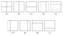
도 4는 발명이 적용되는 일 실시예로서, 쿼드 트리(Quad tree) 및 바이너리 트리(Binary tree) 분할(partitioning)이 허용되는 파티션 형태를 나타낸 도면이다.
도 5는 본 발명이 적용되는 일 실시예로서, 쿼드 트리 및 바이너리 트리 분할에 기반하여 코딩 블록을 계층적으로 분할하는 일예를 도시한 것이다.
도 6은 본 발명이 적용되는 일 실시예로서, 쿼드 트리 및 대칭형 바이너리 트리 분할에 기반하여 코딩 블록을 계층적으로 분할하는 일예를 도시한 것이다.
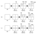
도 7은 본 발명이 적용되는 일 실시예로서, 비대칭형 바이너리 트리 분할이 허용되는 파티션 형태를 나타낸 도면이다.
도 8은 본 발명이 적용되는 일 실시예로서, 쿼드 트리 및 대칭형/비대칭형 바이너리 트리 분할에 기반한 코딩 블록의 분할 형태를 예시한 것이다.
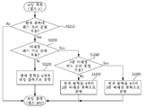
도 9는 본 발명이 적용되는 일 실시예로서, 쿼드 트리 및 바이너리 트리 분할에 기반한 코딩 블록 분할 방법에 대한 흐름도이다.
도 10은 본 발명이 적용되는 일 실시예로서, 쿼드 트리 및 바이너리 트리 분할이 적용되는 네트워크 추상화 계층 (NAL)에 포함되는 신택스 요소(syntax element)를 예를 들어 도시한 것이다.
도 11은 본 발명이 적용되는 다른 실시예로서, 비대칭형 쿼드 트리 분할이 허용되는 파티션 형태를 나타낸 도면이다.
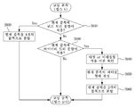
도 12는 본 발명이 적용되는 다른 실시예로서, 비대칭형 쿼드 트리 분할에 기반한 코딩 블록 분할 방법에 대한 흐름도이다.
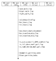
도 13은 본 발명이 적용되는 다른 실시예로서, 비대칭형 쿼드 트리 분할이 적용되는 네트워크 추상화 계층 (NAL)에 포함되는 신택스 요소(syntax element)를 예를 들어 도시한 것이다.
도 14는 본 발명이 적용되는 또 다른 실시예로서, 쿼드 트리 및 트리플 트리 분할이 허용되는 파티션 형태를 나타낸 도면이다.
도 15는 본 발명이 적용되는 또 다른 실시예로서, 쿼드 트리 및 트리플 트리 분할 에 기반한 코딩 블록 분할 방법에 대한 흐름도이다.
도 16은 본 발명이 적용되는 또 다른 실시예로서, 쿼드 트리 및 트리플 트리 분할이 적용되는 네트워크 추상화 계층 (NAL)에 포함되는 신택스 요소(syntax element)를 예를 들어 도시한 것이다.
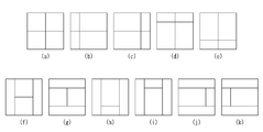
도 17은 본 발명이 적용되는 또 다른 실시예로서, 멀티 트리 분할이 허용되는 기본 파티션 형태를 나타낸 도면이다.
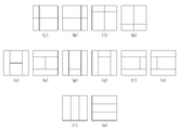
도 18은 본 발명이 적용되는 또 다른 실시예로서, 멀티 트리 분할이 허용되는 확장된 파티션 형태를 나타낸 도면이다.
도 19는 본 발명이 적용되는 또 다른 실시예로서, 멀티 트리 분할에 기반한 코딩 블록 분할 방법에 대한 흐름도이다.
도 20은 본 발명이 적용되는 일실시예로서, 영상 부호화기/복호화기에 기-정의된 인트라 예측 모드의 종류를 도시한 것이다.
도 21은 본 발명이 적용되는 일실시예로서, 영상 부호화기/복호화기에 확장된인트라 예측 모드의 종류를 도시한 것이다.
도 22는본 발명이 적용되는 일실시예로서, 인트라 예측 방법을 개략적으로 도시한 순서도이다.
도 23은 본 발명이 적용되는 일실시예로서, 주변 샘플들의 차분 정보에 기반하여 현재 블록의 예측 샘플을 보정하는 방법을 도시한 것이다.
도24 및 도 25는 본 발명이 적용되는 일실시예로서, 소정의 보정 필터를 기반으로 예측 샘플을 보정하는 방법을 도시한 것이다.
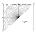
도 26은 도 20에 도시된 방향성 인트라 예측 모드인 Mode 2부터 Mode 34까지의 인트라 방향 파라미터(intraPredAng)를 나타낸 테이블이다.
도 27 및 도 28은 본 발명에 따른, 참조 샘플들이 일렬로 재배열된 일차원 레퍼런스 샘플 그룹을 나타낸 도면이다.
도 29는 본 발명이 적용되는 실시예로서, 코딩 유닛의 종류에 따라 상이한 보간 필터를 적용하는 흐름도를 도시한 것이다.
도 30 내지 도 32는 본 발명이 적용되는 실시예로서, 코딩 유닛의 종류에 따라 상이한 보간 필터를 적용하는 흐름도를 예시적으로 도시한 것이다.
도 33은 본 발명이 적용되는 또 다른 실시예로서, 인트라 예측 샘플 보간에 적용되는 네트워크 추상화 계층 (NAL)에 포함되는 신택스 요소(syntax element)를 예를 들어 도시한 것이다.1 is a block diagram illustrating an image encoding apparatus according to an embodiment of the present invention.
2 is a block diagram illustrating an image decoding apparatus according to an embodiment of the present invention.
3 is a diagram illustrating a partition mode that can be applied to a coding block when a coding block is coded by inter-picture prediction.
FIG. 4 is a diagram illustrating a partition type in which a quad tree and a binary tree partitioning are allowed, according to an embodiment of the present invention.
FIG. 5 illustrates an example in which a coding block is hierarchically divided based on quad tree and binary tree partitioning according to an embodiment to which the present invention is applied.
FIG. 6 illustrates an example of hierarchically dividing a coding block based on quad tree and symmetric binary tree partitioning according to an embodiment of the present invention. Referring to FIG.
FIG. 7 is a diagram illustrating a partition type in which asymmetric binary tree partitioning is permitted according to an embodiment to which the present invention is applied.
FIG. 8 illustrates an embodiment of the present invention to which a coding block is divided based on a quadtree and a symmetric / asymmetric binary tree division.
9 is a flowchart illustrating a method of dividing a coding block based on quad tree and binary tree partitioning according to an embodiment of the present invention.
FIG. 10 illustrates an example of a syntax element included in a network abstraction layer (NAL) to which a quadtree and a binary tree are applied, according to an embodiment of the present invention.
FIG. 11 is a diagram illustrating a partition type in which asymmetric quadtree partitioning is allowed according to another embodiment to which the present invention is applied.
12 is a flowchart illustrating a method of dividing a coding block based on an asymmetric quadtree division according to another embodiment to which the present invention is applied.
FIG. 13 illustrates a syntax element included in a network abstraction layer (NAL) to which an asymmetric quadtree division is applied according to another embodiment to which the present invention is applied.
FIG. 14 is a diagram illustrating a partition type in which quad tree and triple tree partitioning are allowed as another embodiment to which the present invention is applied.
15 is a flowchart illustrating a method of dividing a coding block based on quad tree and triple tree partitioning according to another embodiment of the present invention.
FIG. 16 illustrates a syntax element included in a network abstraction layer (NAL) to which a quadtree and a triple tree are applied, according to another embodiment of the present invention.
FIG. 17 is a diagram illustrating a basic partition type in which multi-tree partitioning is permitted according to another embodiment of the present invention.
18 is a diagram illustrating an extended partition type in which multi-tree partitioning is permitted according to another embodiment of the present invention.
FIG. 19 is a flowchart of a method of dividing a coding block based on multi-tree partitioning according to another embodiment to which the present invention is applied.
FIG. 20 illustrates an intra prediction mode defined in an image encoder / decoder according to an embodiment of the present invention. Referring to FIG.
FIG. 21 illustrates a type of an intra prediction mode extended to an image encoder / decoder according to an embodiment of the present invention. Referring to FIG.
22 is a flowchart schematically showing an intra prediction method according to an embodiment to which the present invention is applied.
FIG. 23 illustrates a method of correcting a prediction sample of a current block based on difference information of neighboring samples, according to an embodiment of the present invention. Referring to FIG.
24 and 25 illustrate a method of correcting a prediction sample based on a predetermined correction filter according to an embodiment of the present invention.
26 is a table showing intraframe direction parameters (intra prediction) from
27 and 28 are diagrams illustrating a one-dimensional reference sample group in which reference samples are rearranged in a row in accordance with the present invention.
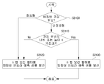
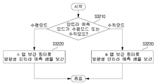
FIG. 29 shows a flow chart for applying different interpolation filters according to the types of coding units to which the present invention is applied.
30 to 32 illustrate a flow chart of applying different interpolation filters according to the types of coding units to which the present invention is applied.
FIG. 33 illustrates an example of a syntax element included in a network abstraction layer (NAL) applied to intra prediction sample interpolation according to another embodiment of the present invention.
본 발명은 다양한 변경을 가할 수 있고 여러 가지 실시예를 가질 수 있는 바, 특정 실시예들을 도면에 예시하고 상세한 설명에 상세하게 설명하고자 한다. 그러나, 이는 본 발명을 특정한 실시 형태에 대해 한정하려는 것이 아니며, 본 발명의 사상 및 기술 범위에 포함되는 모든 변경, 균등물 내지 대체물을 포함하는 것으로 이해되어야 한다. 각 도면을 설명하면서 유사한 참조부호를 유사한 구성요소에 대해 사용하였다.While the invention is susceptible to various modifications and alternative forms, specific embodiments thereof are shown by way of example in the drawings and will herein be described in detail. It should be understood, however, that the invention is not intended to be limited to the particular embodiments, but includes all modifications, equivalents, and alternatives falling within the spirit and scope of the invention. Like reference numerals are used for like elements in describing each drawing.
제1, 제2 등의 용어는 다양한 구성요소들을 설명하는데 사용될 수 있지만, 상기 구성요소들은 상기 용어들에 의해 한정되어서는 안 된다. 상기 용어들은 하나의 구성요소를 다른 구성요소로부터 구별하는 목적으로만 사용된다. 예를 들어, 본 발명의 권리 범위를 벗어나지 않으면서 제1 구성요소는 제2 구성요소로 명명될 수 있고, 유사하게 제2 구성요소도 제1 구성요소로 명명될 수 있다. 및/또는 이라는 용어는 복수의 관련된 기재된 항목들의 조합 또는 복수의 관련된 기재된 항목들 중의 어느 항목을 포함한다.The terms first, second, etc. may be used to describe various components, but the components should not be limited by the terms. The terms are used only for the purpose of distinguishing one component from another. For example, without departing from the scope of the present invention, the first component may be referred to as a second component, and similarly, the second component may also be referred to as a first component. And / or < / RTI > includes any combination of a plurality of related listed items or any of a plurality of related listed items.
본 출원에서 사용한 용어는 단지 특정한 실시예를 설명하기 위해 사용된 것으로, 본 발명을 한정하려는 의도가 아니다. 단수의 표현은 문맥상 명백하게 다르게 뜻하지 않는 한, 복수의 표현을 포함한다. 본 출원에서, "포함하다" 또는 "가지다" 등의 용어는 명세서상에 기재된 특징, 숫자, 단계, 동작, 구성요소, 부품 또는 이들을 조합한 것이 존재함을 지정하려는 것이지, 하나 또는 그 이상의 다른 특징들이나 숫자, 단계, 동작, 구성요소, 부품 또는 이들을 조합한 것들의 존재 또는 부가 가능성을 미리 배제하지 않는 것으로 이해되어야 한다.The terminology used herein is for the purpose of describing particular embodiments only and is not intended to be limiting of the invention. The singular expressions include plural expressions unless the context clearly dictates otherwise. In the present application, the terms "comprises" or "having" and the like are used to specify that there is a feature, a number, a step, an operation, an element, a component or a combination thereof described in the specification, But do not preclude the presence or addition of one or more other features, integers, steps, operations, elements, components, or combinations thereof.
또한, 본 출원에서 사용한 “유닛(unit)”은 “블록(block)”으로 대체할 수 있으며, 따라서, 본 명세서에서 “코딩 트리 유닛”과 “코딩 트리 블록”, “코딩 유닛”과 “코딩 블록”, “예측 유닛”과 “예측 블록”, “변환 유닛”과 “변환 블록”은 각각 동일한 의미로 해석할 수 있다.The term " unit " used in the present application may also be replaced by a " block "Quot;, " prediction unit ", " prediction block ", " conversion unit ", and " conversion block "
이하, 첨부한 도면들을 참조하여, 본 발명의 바람직한 실시예를 보다 상세하게 설명하고자 한다. 이하, 도면상의 동일한 구성요소에 대해서는 동일한 참조부호를 사용하고 동일한 구성요소에 대해서 중복된 설명은 생략한다.Hereinafter, preferred embodiments of the present invention will be described in detail with reference to the accompanying drawings. Hereinafter, the same reference numerals will be used for the same constituent elements in the drawings, and redundant explanations for the same constituent elements will be omitted.
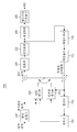
도 1은 본 발명의 일실시예에 따른 영상 부호화 장치를 나타낸 블록도이다. 1 is a block diagram illustrating an image encoding apparatus according to an embodiment of the present invention.
도 1을 참조하면, 영상 부호화 장치(100)는 픽쳐 분할부(110), 예측부(120, 125), 변환부(130), 양자화부(135), 재정렬부(160), 엔트로피 부호화부(165), 역양자화부(140), 역변환부(145), 필터부(150) 및 메모리(155)를 포함할 수 있다.1, the
도 1에 나타난 각 구성부들은 영상 부호화 장치에서 서로 다른 특징적인 기능들을 나타내기 위해 독립적으로 도시한 것으로, 각 구성부들이 분리된 하드웨어나 하나의 소프트웨어 구성단위로 이루어짐을 의미하지 않는다. 즉, 각 구성부는 설명의 편의상 각각의 구성부로 나열하여 포함한 것으로 각 구성부 중 적어도 두 개의 구성부가 합쳐져 하나의 구성부로 이루어지거나, 하나의 구성부가 복수개의 구성부로 나뉘어져 기능을 수행할 수 있고 이러한 각 구성부의 통합된 실시예 및 분리된 실시예도 본 발명의 본질에서 벗어나지 않는 한 본 발명의 권리범위에 포함된다.Each of the components shown in FIG. 1 is shown independently to represent different characteristic functions in the image encoding apparatus, and does not mean that each component is composed of separate hardware or one software configuration unit. That is, each constituent unit is included in each constituent unit for convenience of explanation, and at least two constituent units of the constituent units may be combined to form one constituent unit, or one constituent unit may be divided into a plurality of constituent units to perform a function. The integrated embodiments and separate embodiments of the components are also included within the scope of the present invention, unless they depart from the essence of the present invention.
또한, 일부의 구성 요소는 본 발명에서 본질적인 기능을 수행하는 필수적인 구성 요소는 아니고 단지 성능을 향상시키기 위한 선택적 구성 요소일 수 있다. 본 발명은 단지 성능 향상을 위해 사용되는 구성 요소를 제외한 본 발명의 본질을 구현하는데 필수적인 구성부만을 포함하여 구현될 수 있고, 단지 성능 향상을 위해 사용되는 선택적 구성 요소를 제외한 필수 구성 요소만을 포함한 구조도 본 발명의 권리범위에 포함된다.In addition, some of the components are not essential components to perform essential functions in the present invention, but may be optional components only to improve performance. The present invention can be implemented only with components essential for realizing the essence of the present invention, except for the components used for the performance improvement, and can be implemented by only including the essential components except the optional components used for performance improvement Are also included in the scope of the present invention.
픽쳐 분할부(110)는 입력된 픽쳐를 적어도 하나의 처리 단위로 분할할 수 있다. 이때, 처리 단위는 예측 단위(Prediction Unit: PU)일 수도 있고, 변환 단위(Transform Unit: TU)일 수도 있으며, 부호화 단위(Coding Unit: CU)일 수도 있다. 픽쳐 분할부(110)에서는 하나의 픽쳐에 대해 복수의 부호화 단위, 예측 단위 및 변환 단위의 조합으로 분할하고 소정의 기준(예를 들어, 비용 함수)으로 하나의 부호화 단위, 예측 단위 및 변환 단위 조합을 선택하여 픽쳐를 부호화 할 수 있다.The
예를 들어, 하나의 픽쳐는 복수개의 부호화 단위로 분할될 수 있다. 픽쳐에서 부호화 단위를 분할하기 위해서는 쿼드 트리 구조(Quad Tree Structure)와 같은 재귀적인 트리 구조를 사용할 수 있는데 하나의 영상 또는 최대 크기 부호화 단위(largest coding unit)를 루트로 하여 다른 부호화 단위로 분할되는 부호화 유닛은 분할된 부호화 단위의 개수만큼의 자식 노드를 가지고 분할될 수 있다. 일정한 제한에 따라 더 이상 분할되지 않는 부호화 단위는 리프 노드가 된다. 즉, 하나의 코딩 유닛에 대하여 정방형 분할만이 가능하다고 가정하는 경우, 하나의 부호화 단위는 최대 4개의 다른 부호화 단위로 분할될 수 있다.For example, one picture may be divided into a plurality of coding units. In order to divide a coding unit in a picture, a recursive tree structure such as a quad tree structure can be used. In a coding or decoding scheme in which one picture or a largest coding unit is used as a root and divided into other coding units A unit can be divided with as many child nodes as the number of divided coding units. Under certain constraints, an encoding unit that is no longer segmented becomes a leaf node. That is, when it is assumed that only one square division is possible for one coding unit, one coding unit can be divided into a maximum of four different coding units.
이하, 본 발명의 실시예에서는 부호화 단위는 부호화를 수행하는 단위의 의미로 사용할 수도 있고, 복호화를 수행하는 단위의 의미로 사용할 수도 있다.Hereinafter, in the embodiment of the present invention, a coding unit may be used as a unit for performing coding, or may be used as a unit for performing decoding.
예측 단위는 하나의 부호화 단위 내에서 동일한 크기의 적어도 하나의 정사각형 또는 직사각형 등의 형태를 가지고 분할된 것일 수도 있고, 하나의 부호화 단위 내에서 분할된 예측 단위 중 어느 하나의 예측 단위가 다른 하나의 예측 단위와 상이한 형태 및/또는 크기를 가지도록 분할된 것일 수도 있다.The prediction unit may be one divided into at least one square or rectangular shape having the same size in one coding unit, and one of the prediction units in one coding unit may be divided into another prediction Or may have a shape and / or size different from the unit.
부호화 단위를 기초로 인트라 예측을 수행하는 예측 단위를 생성시 최소 부호화 단위가 아닌 경우, 복수의 예측 단위 NxN 으로 분할하지 않고 인트라 예측을 수행할 수 있다.If a prediction unit performing intra prediction on the basis of an encoding unit is not the minimum encoding unit at the time of generation, intraprediction can be performed without dividing the prediction unit into a plurality of prediction units NxN.
예측부(120, 125)는 인터 예측을 수행하는 인터 예측부(120)와 인트라 예측을 수행하는 인트라 예측부(125)를 포함할 수 있다. 예측 단위에 대해 인터 예측을 사용할 것인지 또는 인트라 예측을 수행할 것인지를 결정하고, 각 예측 방법에 따른 구체적인 정보(예컨대, 인트라 예측 모드, 모션 벡터, 참조 픽쳐 등)를 결정할 수 있다. 이때, 예측이 수행되는 처리 단위와 예측 방법 및 구체적인 내용이 정해지는 처리 단위는 다를 수 있다. 예컨대, 예측의 방법과 예측 모드 등은 예측 단위로 결정되고, 예측의 수행은 변환 단위로 수행될 수도 있다. 생성된 예측 블록과 원본 블록 사이의 잔차값(잔차 블록)은 변환부(130)로 입력될 수 있다. 또한, 예측을 위해 사용한 예측 모드 정보, 모션 벡터 정보 등은 잔차값과 함께 엔트로피 부호화부(165)에서 부호화되어 복호화기에 전달될 수 있다. 특정한 부호화 모드를 사용할 경우, 예측부(120, 125)를 통해 예측 블록을 생성하지 않고, 원본 블록을 그대로 부호화하여 복호화부에 전송하는 것도 가능하다.The
인터 예측부(120)는 현재 픽쳐의 이전 픽쳐 또는 이후 픽쳐 중 적어도 하나의 픽쳐의 정보를 기초로 예측 단위를 예측할 수도 있고, 경우에 따라서는 현재 픽쳐 내의 부호화가 완료된 일부 영역의 정보를 기초로 예측 단위를 예측할 수도 있다. 인터 예측부(120)는 참조 픽쳐 보간부, 모션 예측부, 움직임 보상부를 포함할 수 있다. The
참조 픽쳐 보간부에서는 메모리(155)로부터 참조 픽쳐 정보를 제공받고 참조 픽쳐에서 정수 화소 이하의 화소 정보를 생성할 수 있다. 휘도 화소의 경우, 1/4 화소 단위로 정수 화소 이하의 화소 정보를 생성하기 위해 필터 계수를 달리하는 DCT 기반의 8탭 보간 필터(DCT-based Interpolation Filter)가 사용될 수 있다. 색차 신호의 경우 1/8 화소 단위로 정수 화소 이하의 화소 정보를 생성하기 위해 필터 계수를 달리하는 DCT 기반의 4탭 보간 필터(DCT-based Interpolation Filter)가 사용될 수 있다.In the reference picture interpolating section, the reference picture information is supplied from the
모션 예측부는 참조 픽쳐 보간부에 의해 보간된 참조 픽쳐를 기초로 모션 예측을 수행할 수 있다. 모션 벡터를 산출하기 위한 방법으로 FBMA(Full search-based Block Matching Algorithm), TSS(Three Step Search), NTS(New Three-Step Search Algorithm) 등 다양한 방법이 사용될 수 있다. 모션 벡터는 보간된 화소를 기초로 1/2 또는 1/4 화소 단위의 모션 벡터값을 가질 수 있다. 모션 예측부에서는 모션 예측 방법을 다르게 하여 현재 예측 단위를 예측할 수 있다. 모션 예측 방법으로 스킵(Skip) 방법, 머지(Merge) 방법, AMVP(Advanced Motion Vector Prediction) 방법, 인트라 블록 카피(Intra Block Copy) 방법 등 다양한 방법이 사용될 수 있다.The motion prediction unit may perform motion prediction based on the reference picture interpolated by the reference picture interpolating unit. Various methods such as Full Search-based Block Matching Algorithm (FBMA), Three Step Search (TSS), and New Three-Step Search Algorithm (NTS) can be used as methods for calculating motion vectors. The motion vector may have a motion vector value of 1/2 or 1/4 pixel unit based on the interpolated pixel. The motion prediction unit can predict the current prediction unit by making the motion prediction method different. Various methods such as a skip method, a merge method, an AMVP (Advanced Motion Vector Prediction) method, and an Intra Block Copy method can be used as the motion prediction method.
인트라 예측부(125)는 현재 픽쳐 내의 화소 정보인 현재 블록 주변의 참조 픽셀 정보를 기초로 예측 단위를 생성할 수 있다. 현재 예측 단위의 주변 블록이 인터 예측을 수행한 블록이어서, 참조 픽셀이 인터 예측을 수행한 픽셀일 경우, 인터 예측을 수행한 블록에 포함되는 참조 픽셀을 주변의 인트라 예측을 수행한 블록의 참조 픽셀 정보로 대체하여 사용할 수 있다. 즉, 참조 픽셀이 가용하지 않는 경우, 가용하지 않은 참조 픽셀 정보를 가용한 참조 픽셀 중 적어도 하나의 참조 픽셀로 대체하여 사용할 수 있다.The
인트라 예측에서 예측 모드는 참조 픽셀 정보를 예측 방향에 따라 사용하는 방향성 예측 모드와 예측을 수행시 방향성 정보를 사용하지 않는 비방향성 모드를 가질 수 있다. 휘도 정보를 예측하기 위한 모드와 색차 정보를 예측하기 위한 모드가 상이할 수 있고, 색차 정보를 예측하기 위해 휘도 정보를 예측하기 위해 사용된 인트라 예측 모드 정보 또는 예측된 휘도 신호 정보를 활용할 수 있다.In intra prediction, the prediction mode may have a directional prediction mode in which reference pixel information is used according to a prediction direction, and a non-directional mode in which direction information is not used in prediction. The mode for predicting the luminance information may be different from the mode for predicting the chrominance information and the intra prediction mode information or predicted luminance signal information used for predicting the luminance information may be utilized to predict the chrominance information.
인트라 예측을 수행할 때 예측 단위의 크기와 변환 단위의 크기가 동일할 경우, 예측 단위의 좌측에 존재하는 픽셀, 좌측 상단에 존재하는 픽셀, 상단에 존재하는 픽셀을 기초로 예측 단위에 대한 인트라 예측을 수행할 수 있다. 그러나 인트라 예측을 수행할 때 예측 단위의 크기와 변환 단위의 크기가 상이할 경우, 변환 단위를 기초로 한 참조 픽셀을 이용하여 인트라 예측을 수행할 수 있다. 또한, 최소 부호화 단위에 대해서만 NxN 분할을 사용하는 인트라 예측을 사용할 수 있다.When intraprediction is performed, when the size of the prediction unit is the same as the size of the conversion unit, intra prediction is performed on the prediction unit based on pixels existing on the left side of the prediction unit, pixels existing on the upper left side, Can be performed. However, when intra prediction is performed, when the size of the prediction unit differs from the size of the conversion unit, intraprediction can be performed using the reference pixel based on the conversion unit. It is also possible to use intraprediction using NxN partitioning only for the minimum encoding unit.
인트라 예측 방법은 예측 모드에 따라 참조 화소에 AIS(Adaptive Intra Smoothing) 필터를 적용한 후 예측 블록을 생성할 수 있다. 참조 화소에 적용되는 AIS 필터의 종류는 상이할 수 있다. 인트라 예측 방법을 수행하기 위해 현재 예측 단위의 인트라 예측 모드는 현재 예측 단위의 주변에 존재하는 예측 단위의 인트라 예측 모드로부터 예측할 수 있다. 주변 예측 단위로부터 예측된 모드 정보를 이용하여 현재 예측 단위의 예측 모드를 예측하는 경우, 현재 예측 단위와 주변 예측 단위의 인트라 예측 모드가 동일하면 소정의 플래그 정보를 이용하여 현재 예측 단위와 주변 예측 단위의 예측 모드가 동일하다는 정보를 전송할 수 있고, 만약 현재 예측 단위와 주변 예측 단위의 예측 모드가 상이하면 엔트로피 부호화를 수행하여 현재 블록의 예측 모드 정보를 부호화할 수 있다.The intra prediction method can generate a prediction block after applying an AIS (Adaptive Intra Smoothing) filter to the reference pixel according to the prediction mode. The type of the AIS filter applied to the reference pixel may be different. In order to perform the intra prediction method, the intra prediction mode of the current prediction unit can be predicted from the intra prediction mode of the prediction unit existing around the current prediction unit. In the case where the prediction mode of the current prediction unit is predicted using the mode information predicted from the peripheral prediction unit, if the intra prediction mode of the current prediction unit is the same as the intra prediction mode of the current prediction unit, The prediction mode information of the current block can be encoded by performing entropy encoding if the prediction mode of the current prediction unit is different from the prediction mode of the neighbor prediction unit.
또한, 예측부(120, 125)에서 생성된 예측 단위를 기초로 예측을 수행한 예측 단위와 예측 단위의 원본 블록과 차이값인 잔차값(Residual) 정보를 포함하는 잔차 블록이 생성될 수 있다. 생성된 잔차 블록은 변환부(130)로 입력될 수 있다. In addition, a residual block including a prediction unit that has been predicted based on the prediction unit generated by the
변환부(130)에서는 원본 블록과 예측부(120, 125)를 통해 생성된 예측 단위의 잔차값(residual)정보를 포함한 잔차 블록을 DCT(Discrete Cosine Transform), DST(Discrete Sine Transform), KLT와 같은 변환 방법을 사용하여 변환시킬 수 있다. 잔차 블록을 변환하기 위해 DCT를 적용할지, DST를 적용할지 또는 KLT를 적용할지는 잔차 블록을 생성하기 위해 사용된 예측 단위의 인트라 예측 모드 정보를 기초로 결정할 수 있다. The
양자화부(135)는 변환부(130)에서 주파수 영역으로 변환된 값들을 양자화할 수 있다. 블록에 따라 또는 영상의 중요도에 따라 양자화 계수는 변할 수 있다. 양자화부(135)에서 산출된 값은 역양자화부(140)와 재정렬부(160)에 제공될 수 있다.The
재정렬부(160)는 양자화된 잔차값에 대해 계수값의 재정렬을 수행할 수 있다.The
재정렬부(160)는 계수 스캐닝(Coefficient Scanning) 방법을 통해 2차원의 블록 형태 계수를 1차원의 벡터 형태로 변경할 수 있다. 예를 들어, 재정렬부(160)에서는 지그-재그 스캔(Zig-Zag Scan)방법을 이용하여 DC 계수부터 고주파수 영역의 계수까지 스캔하여 1차원 벡터 형태로 변경시킬 수 있다. 변환 단위의 크기 및 인트라 예측 모드에 따라 지그-재그 스캔 대신 2차원의 블록 형태 계수를 열 방향으로 스캔하는 수직 스캔, 2차원의 블록 형태 계수를 행 방향으로 스캔하는 수평 스캔이 사용될 수도 있다. 즉, 변환 단위의 크기 및 인트라 예측 모드에 따라 지그-재그 스캔, 수직 방향 스캔 및 수평 방향 스캔 중 어떠한 스캔 방법이 사용될지 여부를 결정할 수 있다.The
엔트로피 부호화부(165)는 재정렬부(160)에 의해 산출된 값들을 기초로 엔트로피 부호화를 수행할 수 있다. 엔트로피 부호화는 예를 들어, 지수 골롬(Exponential Golomb), CAVLC(Context-Adaptive Variable Length Coding), CABAC(Context-Adaptive Binary Arithmetic Coding)과 같은 다양한 부호화 방법을 사용할 수 있다.The
엔트로피 부호화부(165)는 재정렬부(160) 및 예측부(120, 125)로부터 부호화 단위의 잔차값 계수 정보 및 블록 타입 정보, 예측 모드 정보, 분할 단위 정보, 예측 단위 정보 및 전송 단위 정보, 모션 벡터 정보, 참조 프레임 정보, 블록의 보간 정보, 필터링 정보 등 다양한 정보를 부호화할 수 있다. The
엔트로피 부호화부(165)에서는 재정렬부(160)에서 입력된 부호화 단위의 계수값을 엔트로피 부호화할 수 있다.The
역양자화부(140) 및 역변환부(145)에서는 양자화부(135)에서 양자화된 값들을 역양자화하고 변환부(130)에서 변환된 값들을 역변환한다. 역양자화부(140) 및 역변환부(145)에서 생성된 잔차값(Residual)은 예측부(120, 125)에 포함된 움직임 추정부, 움직임 보상부 및 인트라 예측부를 통해서 예측된 예측 단위와 합쳐져 복원 블록(Reconstructed Block)을 생성할 수 있다. The
필터부(150)는 디블록킹 필터, 오프셋 보정부, ALF(Adaptive Loop Filter)중 적어도 하나를 포함할 수 있다.The
디블록킹 필터는 복원된 픽쳐에서 블록간의 경계로 인해 생긴 블록 왜곡을 제거할 수 있다. 디블록킹을 수행할지 여부를 판단하기 위해 블록에 포함된 몇 개의 열 또는 행에 포함된 픽셀을 기초로 현재 블록에 디블록킹 필터 적용할지 여부를 판단할 수 있다. 블록에 디블록킹 필터를 적용하는 경우 필요한 디블록킹 필터링 강도에 따라 강한 필터(Strong Filter) 또는 약한 필터(Weak Filter)를 적용할 수 있다. 또한 디블록킹 필터를 적용함에 있어 수직 필터링 및 수평 필터링 수행시 수평 방향 필터링 및 수직 방향 필터링이 병행 처리되도록 할 수 있다.The deblocking filter can remove block distortion caused by the boundary between the blocks in the reconstructed picture. It may be determined whether to apply a deblocking filter to the current block based on pixels included in a few columns or rows included in the block to determine whether to perform deblocking. When a deblocking filter is applied to a block, a strong filter or a weak filter may be applied according to the deblocking filtering strength required. In applying the deblocking filter, horizontal filtering and vertical filtering may be performed concurrently in performing vertical filtering and horizontal filtering.
오프셋 보정부는 디블록킹을 수행한 영상에 대해 픽셀 단위로 원본 영상과의 오프셋을 보정할 수 있다. 특정 픽쳐에 대한 오프셋 보정을 수행하기 위해 영상에 포함된 픽셀을 일정한 수의 영역으로 구분한 후 오프셋을 수행할 영역을 결정하고 해당 영역에 오프셋을 적용하는 방법 또는 각 픽셀의 에지 정보를 고려하여 오프셋을 적용하는 방법을 사용할 수 있다.The offset correction unit may correct the offset of the deblocked image with respect to the original image in units of pixels. In order to perform offset correction for a specific picture, pixels included in an image are divided into a predetermined number of areas, and then an area to be offset is determined and an offset is applied to the area. Alternatively, Can be used.
ALF(Adaptive Loop Filtering)는 필터링한 복원 영상과 원래의 영상을 비교한 값을 기초로 수행될 수 있다. 영상에 포함된 픽셀을 소정의 그룹으로 나눈 후 해당 그룹에 적용될 하나의 필터를 결정하여 그룹마다 차별적으로 필터링을 수행할 수 있다. ALF를 적용할지 여부에 관련된 정보는 휘도 신호는 부호화 단위(Coding Unit, CU) 별로 전송될 수 있고, 각각의 블록에 따라 적용될 ALF 필터의 모양 및 필터 계수는 달라질 수 있다. 또한, 적용 대상 블록의 특성에 상관없이 동일한 형태(고정된 형태)의 ALF 필터가 적용될 수도 있다. Adaptive Loop Filtering (ALF) can be performed based on a comparison between the filtered reconstructed image and the original image. After dividing the pixels included in the image into a predetermined group, one filter to be applied to the group may be determined and different filtering may be performed for each group. The information related to whether to apply the ALF may be transmitted for each coding unit (CU), and the shape and the filter coefficient of the ALF filter to be applied may be changed according to each block. Also, an ALF filter of the same type (fixed form) may be applied irrespective of the characteristics of the application target block.
메모리(155)는 필터부(150)를 통해 산출된 복원 블록 또는 픽쳐를 저장할 수 있고, 저장된 복원 블록 또는 픽쳐는 인터 예측을 수행 시 예측부(120, 125)에 제공될 수 있다.The
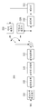
도 2는 본 발명의 일실시예에 따른 영상 복호화 장치를 나타낸 블록도이다.2 is a block diagram illustrating an image decoding apparatus according to an embodiment of the present invention.
도 2를 참조하면, 영상 복호화기(200)는 엔트로피 복호화부(210), 재정렬부(215), 역양자화부(220), 역변환부(225), 예측부(230, 235), 필터부(240), 메모리(245)가 포함될 수 있다.2, the
영상 부호화기에서 영상 비트스트림이 입력된 경우, 입력된 비트스트림은 영상 부호화기와 반대의 절차로 복호화될 수 있다.When an image bitstream is input in the image encoder, the input bitstream may be decoded in a procedure opposite to that of the image encoder.
엔트로피 복호화부(210)는 영상 부호화기의 엔트로피 부호화부에서 엔트로피 부호화를 수행한 것과 반대의 절차로 엔트로피 복호화를 수행할 수 있다. 예를 들어, 영상 부호화기에서 수행된 방법에 대응하여 지수 골롬(Exponential Golomb), CAVLC(Context-Adaptive Variable Length Coding), CABAC(Context-Adaptive Binary Arithmetic Coding)과 같은 다양한 방법이 적용될 수 있다. The
엔트로피 복호화부(210)에서는 부호화기에서 수행된 인트라 예측 및 인터 예측에 관련된 정보를 복호화할 수 있다.The
재정렬부(215)는 엔트로피 복호화부(210)에서 엔트로피 복호화된 비트스트림을 부호화부에서 재정렬한 방법을 기초로 재정렬을 수행할 수 있다. 1차원 벡터 형태로 표현된 계수들을 다시 2차원의 블록 형태의 계수로 복원하여 재정렬할 수 있다. 재정렬부(215)에서는 부호화부에서 수행된 계수 스캐닝에 관련된 정보를 제공받고 해당 부호화부에서 수행된 스캐닝 순서에 기초하여 역으로 스캐닝하는 방법을 통해 재정렬을 수행할 수 있다.The
역양자화부(220)는 부호화기에서 제공된 양자화 파라미터와 재정렬된 블록의 계수값을 기초로 역양자화를 수행할 수 있다. The
역변환부(225)는 영상 부호화기에서 수행한 양자화 결과에 대해 변환부에서 수행한 변환 즉, DCT, DST, 및 KLT에 대해 역변환 즉, 역 DCT, 역 DST 및 역 KLT를 수행할 수 있다. 역변환은 영상 부호화기에서 결정된 전송 단위를 기초로 수행될 수 있다. 영상 복호화기의 역변환부(225)에서는 예측 방법, 현재 블록의 크기 및 예측 방향 등 복수의 정보에 따라 변환 기법(예를 들어, DCT, DST, KLT)이 선택적으로 수행될 수 있다.The
예측부(230, 235)는 엔트로피 복호화부(210)에서 제공된 예측 블록 생성 관련 정보와 메모리(245)에서 제공된 이전에 복호화된 블록 또는 픽쳐 정보를 기초로 예측 블록을 생성할 수 있다. The
전술한 바와 같이 영상 부호화기에서의 동작과 동일하게 인트라 예측을 수행시 예측 단위의 크기와 변환 단위의 크기가 동일할 경우, 예측 단위의 좌측에 존재하는 픽셀, 좌측 상단에 존재하는 픽셀, 상단에 존재하는 픽셀을 기초로 예측 단위에 대한 인트라 예측을 수행하지만, 인트라 예측을 수행시 예측 단위의 크기와 변환 단위의 크기가 상이할 경우, 변환 단위를 기초로 한 참조 픽셀을 이용하여 인트라 예측을 수행할 수 있다. 또한, 최소 부호화 단위에 대해서만 NxN 분할을 사용하는 인트라 예측을 사용할 수도 있다.As described above, when intra prediction is performed in the same manner as in the image encoder, when the size of the prediction unit is the same as the size of the conversion unit, pixels existing on the left side of the prediction unit, pixels existing on the upper left side, However, when the size of the prediction unit differs from the size of the prediction unit in intra prediction, intraprediction is performed using a reference pixel based on the conversion unit . It is also possible to use intra prediction using NxN division only for the minimum coding unit.
예측부(230, 235)는 예측 단위 판별부, 인터 예측부 및 인트라 예측부를 포함할 수 있다. 예측 단위 판별부는 엔트로피 복호화부(210)에서 입력되는 예측 단위 정보, 인트라 예측 방법의 예측 모드 정보, 인터 예측 방법의 모션 예측 관련 정보 등 다양한 정보를 입력 받고 현재 부호화 단위에서 예측 단위를 구분하고, 예측 단위가 인터 예측을 수행하는지 아니면 인트라 예측을 수행하는지 여부를 판별할 수 있다. 인터 예측부(230)는 영상 부호화기에서 제공된 현재 예측 단위의 인터 예측에 필요한 정보를 이용해 현재 예측 단위가 포함된 현재 픽쳐의 이전 픽쳐 또는 이후 픽쳐 중 적어도 하나의 픽쳐에 포함된 정보를 기초로 현재 예측 단위에 대한 인터 예측을 수행할 수 있다. 또는, 현재 예측 단위가 포함된 현재 픽쳐 내에서 기-복원된 일부 영역의 정보를 기초로 인터 예측을 수행할 수도 있다.The
인터 예측을 수행하기 위해 부호화 단위를 기준으로 해당 부호화 단위에 포함된 예측 단위의 모션 예측 방법이 스킵 모드(Skip Mode), 머지 모드(Merge 모드), AMVP 모드(AMVP Mode), 인트라 블록 카피 모드 중 어떠한 방법인지 여부를 판단할 수 있다.In order to perform inter prediction, a motion prediction method of a prediction unit included in a corresponding encoding unit on the basis of an encoding unit includes a skip mode, a merge mode, an AMVP mode, and an intra block copy mode It is possible to judge whether or not it is any method.
인트라 예측부(235)는 현재 픽쳐 내의 화소 정보를 기초로 예측 블록을 생성할 수 있다. 예측 단위가 인트라 예측을 수행한 예측 단위인 경우, 영상 부호화기에서 제공된 예측 단위의 인트라 예측 모드 정보를 기초로 인트라 예측을 수행할 수 있다. 인트라 예측부(235)에는 AIS(Adaptive Intra Smoothing) 필터, 참조 화소 보간부, DC 필터를 포함할 수 있다. AIS 필터는 현재 블록의 참조 화소에 필터링을 수행하는 부분으로써 현재 예측 단위의 예측 모드에 따라 필터의 적용 여부를 결정하여 적용할 수 있다. 영상 부호화기에서 제공된 예측 단위의 예측 모드 및 AIS 필터 정보를 이용하여 현재 블록의 참조 화소에 AIS 필터링을 수행할 수 있다. 현재 블록의 예측 모드가 AIS 필터링을 수행하지 않는 모드일 경우, AIS 필터는 적용되지 않을 수 있다.The
참조 화소 보간부는 예측 단위의 예측 모드가 참조 화소를 보간한 화소값을 기초로 인트라 예측을 수행하는 예측 단위일 경우, 참조 화소를 보간하여 정수값 이하의 화소 단위의 참조 화소를 생성할 수 있다. 현재 예측 단위의 예측 모드가 참조 화소를 보간하지 않고 예측 블록을 생성하는 예측 모드일 경우 참조 화소는 보간되지 않을 수 있다. DC 필터는 현재 블록의 예측 모드가 DC 모드일 경우 필터링을 통해서 예측 블록을 생성할 수 있다.The reference pixel interpolator may interpolate the reference pixels to generate reference pixels in units of pixels less than or equal to an integer value when the prediction mode of the prediction unit is a prediction unit that performs intra prediction based on pixel values obtained by interpolating reference pixels. The reference pixel may not be interpolated in the prediction mode in which the prediction mode of the current prediction unit generates the prediction block without interpolating the reference pixel. The DC filter can generate a prediction block through filtering when the prediction mode of the current block is the DC mode.
복원된 블록 또는 픽쳐는 필터부(240)로 제공될 수 있다. 필터부(240)는 디블록킹 필터, 오프셋 보정부, ALF를 포함할 수 있다.The restored block or picture may be provided to the
영상 부호화기로부터 해당 블록 또는 픽쳐에 디블록킹 필터를 적용하였는지 여부에 대한 정보 및 디블록킹 필터를 적용하였을 경우, 강한 필터를 적용하였는지 또는 약한 필터를 적용하였는지에 대한 정보를 제공받을 수 있다. 영상 복호화기의 디블록킹 필터에서는 영상 부호화기에서 제공된 디블록킹 필터 관련 정보를 제공받고 영상 복호화기에서 해당 블록에 대한 디블록킹 필터링을 수행할 수 있다. When information on whether a deblocking filter is applied to a corresponding block or picture from the image encoder or a deblocking filter is applied, information on whether a strong filter or a weak filter is applied can be provided. In the deblocking filter of the video decoder, the deblocking filter related information provided by the video encoder is provided, and the video decoder can perform deblocking filtering for the corresponding block.
오프셋 보정부는 부호화시 영상에 적용된 오프셋 보정의 종류 및 오프셋 값 정보 등을 기초로 복원된 영상에 오프셋 보정을 수행할 수 있다.The offset correction unit may perform offset correction on the reconstructed image based on the type of offset correction applied to the image and the offset value information during encoding.
ALF는 부호화기로부터 제공된 ALF 적용 여부 정보, ALF 계수 정보 등을 기초로 부호화 단위에 적용될 수 있다. 이러한 ALF 정보는 특정한 파라메터 셋에 포함되어 제공될 수 있다.The ALF can be applied to an encoding unit on the basis of ALF application information and ALF coefficient information provided from an encoder. Such ALF information may be provided in a specific parameter set.
메모리(245)는 복원된 픽쳐 또는 블록을 저장하여 참조 픽쳐 또는 참조 블록으로 사용할 수 있도록 할 수 있고 또한 복원된 픽쳐를 출력부로 제공할 수 있다. The
전술한 바와 같이 이하, 본 발명의 실시예에서는 설명의 편의상 코딩 유닛(Coding Unit)을 부호화 단위라는 용어로 사용하지만, 부호화뿐만 아니라 복호화를 수행하는 단위가 될 수도 있다.As described above, in the embodiment of the present invention, a coding unit (coding unit) is used as a coding unit for convenience of explanation, but it may be a unit for performing not only coding but also decoding.
또한, 현재 블록은, 부호화/복호화 대상 블록을 나타내는 것으로,부호화/복호화 단계에 따라, 코딩 트리 블록(또는 코딩 트리 유닛), 부호화 블록(또는 부호화 유닛), 변환 블록(또는 변환 유닛) 또는 예측 블록(또는 예측 유닛) 등을 나타내는 것일 수 있다. 본 명세서에서, '유닛'은 특정 부호화/복호화 프로세스를 수행하기 위한 기본 단위를 나타내고, '블록'은 소정 크기의 샘플 어레이를 나타낼 수 있다. 별도의 구분이 없는 한, '블록'과 '유닛'은 동등한 의미로 사용될 수 있다. 예컨대, 후술되는 실시예에서, 부호화 블록(코딩 블록) 및 부호화 유닛(코딩 유닛)은 상호 동등한 의미인 것으로 이해될 수 있다. The current block indicates a block to be coded / decoded. Depending on the coding / decoding step, the current block includes a coding tree block (or coding tree unit), a coding block (or coding unit), a transform block (Or prediction unit), and the like. In this specification, 'unit' represents a basic unit for performing a specific encoding / decoding process, and 'block' may represent a sample array of a predetermined size. Unless otherwise indicated, the terms 'block' and 'unit' may be used interchangeably. For example, in the embodiments described below, it can be understood that the encoding block (coding block) and the encoding unit (coding unit) have mutually equivalent meanings.
하나의 픽쳐는 정방형 또는 비정방형의 기본 블록으로 분할되어 부호화/복호화될 수 있다. 이때, 기본 블록은, 코딩 트리 유닛(Coding Tree Unit)이라 호칭될 수 있다. 코딩 트리 유닛은, 시퀀스 또는 슬라이스에서 허용하는 가장 큰 크기의 코딩 유닛으로 정의될 수도 있다. 코딩 트리 유닛이 정방형 또는 비정방형인지 여부 또는 코딩 트리 유닛의 크기와 관련한 정보는 시퀀스 파라미터 셋트, 픽처 파라미터 셋트 또는 슬라이스 헤더 등을 통해 시그널링될 수 있다. 코딩 트리 유닛은 더 작은 크기의 파티션으로 분할될 수 있다. 이때, 코딩 트리 유닛을 분할함으로써 생성된 파티션을 뎁스 1이라 할 경우, 뎁스 1인 파티션을 분할함으로써 생성된 파티션은 뎁스 2로 정의될 수 있다. 즉, 코딩 트리 유닛 내 뎁스 k인 파티션을 분할함으로써 생성된 파티션은 뎁스 k+1을 갖는 것으로 정의될 수 있다.One picture may be divided into a square block or a non-square basic block and then encoded / decoded. At this time, the basic block may be referred to as a coding tree unit. The coding tree unit may be defined as a coding unit of the largest size allowed in a sequence or a slice. Information regarding whether the coding tree unit is square or non-square or about the size of the coding tree unit can be signaled through a sequence parameter set, a picture parameter set, or a slice header. The coding tree unit can be divided into smaller size partitions. In this case, if the partition generated by dividing the coding tree unit is
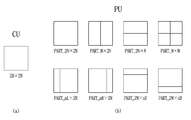
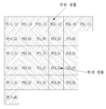
도 3은 코딩 블록이 화면 내 예측 또는 화면 간 예측으로 부호화되었을 때, 코딩 블록에 적용될 수 있는 파티션 모드를 예시한 도면이다.코딩 트리 유닛이 분할됨에 따라 생성된 임의 크기의 파티션을 코딩 유닛이라 정의할 수 있다. 예를 들어, 도 3 (a)는 코딩 유닛이 2Nx2N 크기을 도시하였다. 코딩 유닛은 재귀적으로 분할되거나, 예측, 양자화, 변환 또는 인루프 필터링 등을 수행하기 위한 기본 단위로 분할될 수 있다. 일 예로, 코딩 유닛이 분할됨에 따라 생성된 임의 크기의 파티션은 코딩 유닛으로 정의되거나, 예측, 양자화, 변환 또는 인루프 필터링 등을 수행하기 위한 기본 단위인 변환 유닛(TU: Transform Unit) 또는 예측 유닛(PU: Prediction Unit)으로 정의될 수 있다.3 is a diagram illustrating a partition mode that can be applied to a coding block when the coding block is coded by intra-picture prediction or inter-picture prediction. can do. For example, Figure 3 (a) shows the coding unit 2Nx2N size. The coding unit may be recursively divided or divided into basic units for performing prediction, quantization, transformation, or in-loop filtering, and the like. For example, a partition of arbitrary size generated as a coding unit is divided may be defined as a coding unit or may be a transform unit (TU) or a prediction unit, which is a basic unit for performing prediction, quantization, transformation, (PU: Prediction Unit).
또는, 코딩 블록이 결정되면, 코딩 블록의 예측 분할을 통해 코딩 블록과 동일한 크기 또는 코딩 블록보다 작은 크기를 갖는 예측 블록(Prediction Block)을 결정할 수 있다. 코딩 블록의 예측 분할은 코딩 블록의 분할 형태를 나타내는 파티션 모드(Part_mode)에 의해 수행될 수 있다. 예측 블록의 크기 또는 형태는 코딩 블록의 파티션 모드에 따라 결정될 수 있다. 코딩 블록의 분할 형태는 파티션 후보 중 어느 하나를 특정하는 정보를 통해 결정될 수 있다. 이때, 코딩 블록이 이용할 수 있는 파티션 후보에는 코딩 블록의 크기, 형태 또는 부호화 모드 등에 따라 비대칭 파티션 형태(예컨대, nLx2N, nRx2N, 2NxnU, 2NxnD)가 포함될 수 있다. 일 예로, 코딩 블록이 이용할 수 있는 파티션 후보는 현재 블록의 부호화 모드에 따라 결정될 수 있다. 예를 들어, 코딩 블록이 화면 간 예측으로 부호화된 경우, 코딩 블록에는 도 3 (b)에 도시된 예에서와 같이, 8개의 파티션 모드 중 어느 하나가 적용될 수 있다. 반면, 코딩 블록이 화면 내 예측으로 부호화된 경우, 코딩 블록에는 도 3 (b)의 8개 파티션 모드중 PART_2Nx2N 또는 PART_NxN 이 적용될 수 있다. Alternatively, if a coding block is determined, a prediction block having the same size as the coding block or smaller than the coding block can be determined through predictive division of the coding block. Predictive partitioning of the coded block can be performed by a partition mode (Part_mode) indicating the partition type of the coded block. The size or shape of the prediction block may be determined according to the partition mode of the coding block. The division type of the coding block can be determined through information specifying any one of the partition candidates. At this time, the partition candidates available to the coding block may include an asymmetric partition type (for example, nLx2N, nRx2N, 2NxnU, 2NxnD) depending on the size, type, coding mode or the like of the coding block. In one example, the partition candidate available to the coding block may be determined according to the coding mode of the current block. For example, when a coding block is coded by inter-picture prediction, one of 8 partitioning modes may be applied to the coding block, as in the example shown in Fig. 3 (b). On the other hand, when the coding block is coded by the intra prediction, PART_2Nx2N or PART_NxN among the eight partition modes of FIG. 3B may be applied to the coding block.
PART_NxN은 코딩 블록이 최소 크기를 갖는 경우 적용될 수 있다. 여기서, 코딩 블록의 최소 크기는 부호화기 및 복호화기에서 기 정의된 것일 수 있다. 또는, 코딩 블록의 최소 크기에 관한 정보는 비트스트림을 통해 시그널링될 수도 있다. 일 예로, 코딩 블록의 최소 크기는 슬라이스 헤더를 통해 시그널링되고, 이에 따라, 슬라이스별로 코딩 블록의 최소 크기가 정의될 수 있다. PART_NxN may be applied when the coding block has a minimum size. Here, the minimum size of the coding block may be one previously defined in the encoder and the decoder. Alternatively, information regarding the minimum size of the coding block may be signaled via the bitstream. In one example, the minimum size of the coding block is signaled through the slice header, so that the minimum size of the coding block per slice can be defined.
다른 예로, 코딩 블록이 이용할 수 있는 파티션 후보는 코딩 블록의 크기 또는 형태 중 적어도 하나에 따라 상이하게 결정될 수도 있다. 일 예로, 코딩 블록이 이용할 수 있는 파티션 후보의 개수 또는 종류는 코딩 블록의 크기 또는 형태 중 적어도 하나에 따라 상이하게 결정될 수 있다. In another example, the partition candidates available to the coding block may be determined differently depending on at least one of the size or type of the coding block. In one example, the number or type of partition candidates available to the coding block may be differently determined according to at least one of the size or type of the coding block.
또는, 코딩 블록이 이용할 수 있는 파티션 후보들 중 비대칭 파티션 후보들의 종류 또는 개수를 코딩 블록의 크기 또는 형태에 따라 제한할 수도 있다. 일 예로, 코딩 블록이 이용할 수 있는 비대칭 파티션 후보의 개수 또는 종류는 코딩 블록의 크기 또는 형태 중 적어도 하나에 따라 상이하게 결정될 수 있다.Alternatively, the type or number of asymmetric partition candidates among the partition candidates available to the coding block may be limited depending on the size or type of the coding block. In one example, the number or type of asymmetric partition candidates available to the coding block may be differently determined according to at least one of the size or type of the coding block.
일반적으로, 예측 블록의 크기는 64x64 부터 4x4의 크기를 가질 수 있다. 단, 코딩 블록이 화면 간 예측으로 부호화된 경우, 움직임 보상을 수행할 때, 메모리 대역폭(memory bandwidth)을 줄이기 위해, 예측 블록이 4x4 크기를 갖지 않도록 할 수 있다. In general, the size of the prediction block may have a size from 64x64 to 4x4. However, when the coding block is coded by inter-picture prediction, it is possible to prevent the prediction block from having a 4x4 size in order to reduce the memory bandwidth when performing motion compensation.
파티션 모드를 이용하여, 코딩 블록을 재귀적으로 분할하는 것도 가능하다. 즉, 파티션 인덱스가 지시하는 파티션 모드에 따라 코딩 블록을 분할할 수 있고, 코딩 블록이 분할됨에 따라 생성된 각 파티션이 코딩 블록으로 정의될 수 있다. It is also possible to divide a coded block recursively using the partition mode. That is, the coding block can be divided according to the partition mode indicated by the partition index, and each partition generated as the coding block is divided can be defined as a coding block.
이하, 코딩 유닛을 재귀적으로 분할하는 방법에 대해 보다 상세히 설명하기로 한다. 설명의 편의를 위해, 이하, 코딩 트리 유닛도 코딩 유닛의 범주에 포함되는 것으로 가정 한다. 즉, 후술되는 실시예에서, 코딩 유닛은, 코딩 트리 유닛을 가리키거나, 코딩 트리 유닛이 분할됨에 따라 생성되는 코딩 유닛을 의미할 수 있다. 또한, 코딩 블록이 재귀적으로 분할되는 경우, 코딩 블록이 분할됨에 따라 생성되는 '파티션'은 '코딩 블록'을 의미하는 것으로 이해될 수 있다.Hereinafter, a method of recursively dividing a coding unit will be described in more detail. For convenience of explanation, it is assumed that the coding tree unit is also included in the category of the coding unit. That is, in a later-described embodiment, the coding unit may refer to a coding tree unit, or may refer to a coding unit that is generated as the coding tree unit is divided. Also, when the coding block is recursively divided, it can be understood that the 'partition' generated as the coding block is divided means 'coding block'.
코딩 유닛은 적어도 하나의 라인에 의해 분할될 수 있다. 이때, 코딩 유닛을 분할하는 라인은 소정의 각도를 가질 수도 있다. 여기서, 소정의 각도는, 0도 내지 360도 범위 내의 값일 수 있다. 예컨대, 0도 라인은, 수평 라인, 90도 라인은 수직 라인을 의미하고, 45도 또는 135도 라인은 대각선 라인을 의미할 수 있다. The coding unit may be divided by at least one line. At this time, the line dividing the coding unit may have a predetermined angle. Here, the predetermined angle may be a value within a range of 0 degree to 360 degrees. For example, a 0 degree line means a horizontal line, a 90 degree line means a vertical line, and a 45 degree or 135 degree line can mean a diagonal line.
코딩 유닛이 복수의 라인에 의해 분할되는 경우, 복수의 라인은 모두 동일한 각도를 가질 수 있다. 또는, 복수의 라인 중 적어도 하나는 다른 라인과 상이한 각도를 가질 수도 있다. 또는, 코딩 트리 유닛 또는 코딩 유닛을 분할하는 복수의 라인은 기 정의된 각도 차(예컨대, 90도)를 갖도록 설정될 수도 있다.When the coding unit is divided by a plurality of lines, the plurality of lines may all have the same angle. Alternatively, at least one of the plurality of lines may have an angle different from the other lines. Alternatively, the plurality of lines dividing the coding tree unit or the coding unit may be set to have a predefined angle difference (e.g., 90 degrees).
코딩 트리 유닛 또는 코딩 유닛을 분할하는 라인에 관한 정보는, 파티션 모드로 정의되어 부호화될 수 있다. 또는, 라인의 개수, 방향, 각도, 블록 내 라인의 위치 등에 대한 정보가 부호화될 수도 있다.Information about a line dividing a coding tree unit or a coding unit can be defined and encoded in a partition mode. Alternatively, information on the number of lines, directions, angles, positions of lines in a block, and the like may be encoded.
설명의 편의를 위해, 후술되는 실시예에서는, 코딩 트리 유닛 또는 코딩 유닛은 수직선 및 수평선 중 적어도 하나를 이용하여, 복수의 코딩 유닛으로 분할되는 것으로 가정한다.For convenience of explanation, in the embodiment described below, it is assumed that a coding tree unit or a coding unit is divided into a plurality of coding units using at least one of a vertical line and a horizontal line.
코딩 유닛의 파티셔닝이, 수직선(Vertical Line) 또는 수평선(Horizontal Line) 중 적어도 하나에 기초하여 수행된다고 가정할 때, 코딩 유닛을 파티셔닝하는 수직선 또는 수평선의 개수는 적어도 하나 이상일 수 있다. 일 예로, 하나의 수직선 또는 하나의 수평선을 이용하여, 코딩 트리 유닛 또는 코딩 유닛을 2개의 파티션으로 분할하거나, 두개의 수직선 또는 두개의 수평선을 이용하여, 코딩 유닛을 3개의 파티션으로 분할할 수 있다. 또는, 하나의 수직선 및 하나의 수평선을 이용하여, 코딩 유닛을 길이 및 너비가 1/2 인 4개의 파티션으로 분할할 수도 있다.Assuming that the partitioning of the coding unit is performed based on at least one of a vertical line or a horizontal line, the number of vertical lines or horizontal lines partitioning the coding unit may be at least one or more. In one example, a coding tree unit or a coding unit may be divided into two partitions, or two vertical lines or two horizontal lines may be used to divide a coding unit into three partitions using one vertical line or one horizontal line . Alternatively, one vertical line and one horizontal line may be used to divide the coding unit into four partitions of length and
코딩 트리 유닛 또는 코딩 유닛을 적어도 하나의 수직선 또는 적어도 하나의 수평선을 이용하여 복수의 파티션으로 분할하는 경우, 파티션들은 균일한 크기를 가질 수 있다. 또는, 어느 하나의 파티션이 나머지 파티션과 다른 크기를 갖거나, 각 파티션이 상이한 크기를 가질 수도 있다.If the coding tree unit or coding unit is divided into a plurality of partitions using at least one vertical line or at least one horizontal line, the partitions may have a uniform size. Alternatively, any one partition may have a different size from the remaining partitions, or each partition may have a different size.
후술되는 실시예들에서는, 코딩 유닛이 4개의 파티션으로 분할되는 것을, 쿼드 트리 기반의 분할이라 가정하고, 코딩 유닛이 2개의 파티션으로 분할되는 것을 바이너리 트리 기반의 분할이라 가정한다. 또한, 코딩 유닛이 3개의 파티션으로 분할되는 것을 트리플 트리 기반의 분할이라 가정한다. 또한 상기 적어도 2가지 이상의 분할 방식을 적용하여 분할되는 것을 멀티 트리 기반의 분할이라 가정한다. In the embodiments described below, it is assumed that a coding unit is divided into four partitions, and that a coding unit is divided into two partitions is a binary tree-based parting. It is also assumed that the coding unit is divided into three partitions based on triple tree-based partitioning. In addition, it is assumed that a multi-tree based segmentation is performed by applying at least two or more segmentation methods.
후술되는 도면에서는, 코딩 유닛을 분할하기 위해, 소정 개수의 수직선 또는 소정 개수의 수평선이 이용되는 것으로 도시할 것이나, 도시된 것보다 더 많은 수의 수직선 또는 더 많은 수의 수평선을 이용하여, 코딩 유닛을 도시된 것보다 더 많은 수의 파티션 또는 도시된 것보다 더 적은 수의 파티션으로 분할하는 것 역시 본 발명의 범주에 포함된다고 할 것이다. In the following figures, it is assumed that a predetermined number of vertical lines or a predetermined number of horizontal lines are used to divide the coding unit, but using a greater number of vertical lines or a greater number of horizontal lines than shown, It is also within the scope of the present invention to divide the number of partitions into a larger number of partitions or less than the number of partitions shown.
도 4는 발명이 적용되는 일 실시예로서, 쿼드 트리(Quad tree) 및 바이너리 트리(Binary tree) 분할(partitioning)이 허용되는 파티션 형태를 나타낸 도면이다.FIG. 4 is a diagram illustrating a partition type in which a quad tree and a binary tree partitioning are allowed, according to an embodiment of the present invention.
입력 영상 신호는 소정의 블록 단위로 복호화되며, 이와 같이 입력 영상 신호를 복호화하기 위한 기본 단위를 코딩 블록이라 한다. 코딩 블록은 인트라/인터 예측, 변환, 양자화를 수행하는 단위가 될 수 있다. 또한, 코딩 블록 단위로 예측 모드(예컨대, 화면 내 예측 모드 또는 화면 간 예측 모드)가 결정되고, 코딩 블록에 포함된 예측 블록들은, 결정된 예측 모드를 공유할 수 있다. 코딩 블록은 8x8 내지 64x64 범위에 속하는 임의의 크기를 가진 정방형 또는 비정방형 블록일 수 있고, 128x128, 256x256 또는 그 이상의 크기를 가진 정방형 또는 비정방형 블록일 수 있다. The input video signal is decoded in a predetermined block unit, and a basic unit for decoding the input video signal is called a coding block. The coding block may be a unit for performing intra / inter prediction, conversion, and quantization. Further, a prediction mode (for example, an intra-picture prediction mode or an inter-picture prediction mode) is determined for each coding block, and the prediction blocks included in the coding block can share the determined prediction mode. The coding block may be a square or non-square block having any size falling within the range of 8x8 to 64x64, and may be a square or non-square block having a size of 128x128, 256x256 or more.
구체적으로, 코딩 블록은 쿼드 트리(quad tree)와 바이너리 트리(binary tree) 중 적어도 하나에 기초하여 계층적으로 분할될 수 있다. 여기서, 쿼드 트리 기반의 분할은 2Nx2N 코딩 블록이 4개의 NxN 코딩 블록으로 분할되는 방식(도 4(a))을, 바이너리 트리 기반의 분할은 하나의 코딩 블록이 2개의 코딩 블록으로 분할되는 방식을 각각 의미할 수 있다. 바이너리 트리 기반의 분할이 수행되었다 하더라도, 하위 뎁스에서는 정방형인 코딩 블록이 존재할 수 있다. Specifically, the coding block may be hierarchically partitioned based on at least one of a quad tree and a binary tree. Here, quad tree-based partitioning is a method in which a 2Nx2N coding block is divided into four NxN coding blocks (FIG. 4A), and a binary tree-based partitioning is a method in which one coding block is divided into two coding blocks Respectively. Even if the binary tree-based partitioning is performed, a square-shaped coding block may exist in the lower depth.
바이너리 트리 기반의 분할은 대칭적으로 수행될 수도 있고, 비대칭적으로 수행될 수도 있다. 또한, 바이너리 트리 기반으로 분할된 코딩 블록은 정방형 블록일 수도 있고, 직사각형과 같은 비정방형 블록일 수도 있다. 일 예로, 바이너리 트리 기반의 분할이 허용되는 파티션 형태는 도 4 (b)에 도시된 예에서와 같이, 대칭형(symmetric)인 2NxN (수평 방향 비 정방 코딩 유닛) 또는 Nx2N (수직 방향 비정방 코딩 유닛)이 될 수 있다. 또한, 일 예로, 바이너리 트리 기반의 분할이 허용되는 파티션 형태는 도 4 (c)에 도시된 예에서와 같이, 비대칭형(asymmetric)인 nLx2N, nRx2N, 2NxnU 또는 2NxnD 중 적어도 하나를 포함할 수 있다.Binary tree based partitioning may be performed symmetrically or asymmetrically. In addition, the coding block divided based on the binary tree may be a square block or a non-square block such as a rectangle. As an example, a partition type in which binary tree-based partitioning is allowed may be a symmetric 2NxN (horizontal directional non-punctual coding unit) or Nx2N (vertical direction non-puncturing coding unit, ). Also, as an example, the partition type in which binary tree-based partitioning is allowed may include at least one of nLx2N, nRx2N, 2NxnU, or 2NxnD asymmetric as in the example shown in Fig. 4 (c) .
바이너리 트리 기반의 분할은, 대칭형 또는 비대칭 형태의 파티션 중 어느 하나만 제한적으로 허용될 수도 있다. 이 경우, 코딩 트리 유닛을, 정방형 블록으로 구성하는 것은 쿼드 트리 CU 파티셔닝에 해당하고, 코딩 트리 유닛을, 대칭형인 비정방형 블록으로 구성하는 것은 바이너리 트리 CU 파티셔닝에 해당할 수 있다. 코딩 트리 유닛을 정방형 블록과 대칭형 비정방형 블록으로 구성하는 것은 쿼드 및 바이너리 트리 CU 파티셔닝에 해당할 수 있다.Binary tree-based partitioning may be limited to either a symmetric or an asymmetric partition. In this case, configuring the coding tree unit as a square block corresponds to quad tree CU partitioning, and configuring the coding tree unit as a symmetric non-square block may correspond to binary tree CU partitioning. Constructing the coding tree unit as a square block and a symmetric non-square block may correspond to quad and binary tree CU partitioning.
이하, 상기 쿼드 트리 및 바이너리 트리에 기반한 분할 방식을 QTBT (Quad-Tree & Binary-Tree) 분할로 명명한다. Hereinafter, the division scheme based on the quadtree and the binary tree is referred to as a Quad-Tree & Binary-Tree (QTBT) division.
쿼드 트리 및 바이너리 트리에 기반한 분할 결과, 더 이상 분할되지 않는 코딩 블록은 예측 블록 또는 변환 블록으로 이용될 수 있다. 즉, 쿼드 트리 및 바이너리 트리에 기반한 QTBT (Quad-Tree & Binary-Tree) 분할 방법에서는, 코딩 블록이 예측 블록이 되고, 예측 블록이 변환 블록이 될 수 있다. 일 예로, QTBT 분할 방법을 이용한 경우, 코딩 블록 단위로 예측 영상을 생성하고, 코딩 블록 단위로 원본 영상과 예측 영상간의 차분인 잔차 신호가 변환될 수 있다. 여기서, 코딩 블록 단위로 예측 영상을 생성하는 것은, 코딩 블록을 기준으로 모션 정보가 결정되거나, 코딩 블록을 기준으로 하나의 인트라 예측 모드가 결정되는 것을 의미할 수 있다. 이에 따라, 코딩 블록은, 스킵 모드, 화면 내 예측 또는 화면 간 예측 중 적어도 하나를 이용하여 부호화될 수 있다.As a result of the division based on the quadtree and the binary tree, a coding block which is not further divided can be used as a prediction block or a transform block. That is, in a quad-tree & binary-tree (QTBT) division method based on a quadtree and a binary tree, a coding block becomes a prediction block and a prediction block becomes a transform block. For example, when the QTBT segmentation method is used, a prediction image is generated in units of coding blocks, and a residual signal, which is a difference between the original image and the prediction image, is transformed in units of coding blocks. Here, generating a prediction image in units of coding blocks may mean that motion information is determined based on a coding block or one intra prediction mode is determined based on a coding block. Accordingly, the coding block can be encoded using at least one of a skip mode, intra-picture prediction, or inter-picture prediction.
다른 예로, 코딩 블륵을 분할하여, 코딩 블록보다 작은 크기를 갖는 예측 블록 또는 변환 블록을 이용하는 것도 가능하다.As another example, it is possible to divide a coding block so as to use a prediction block or a transform block having a size smaller than a coding block.
QTBT 분할 방법에서, BT는 대칭형 분할만이 허용되도록 설정될 수 있다. 다만, 블록 경계에서 오브젝트와 배경이 나누어지는 경우에도, 대칭형 이진 분할만을 허용한다면, 부호화 효율이 낮아질 수 있다. 이에 본 발명에서는, 부호화 효율을 높이기 위해, 코딩 블록을 비대칭으로 파티셔닝하는 방법을 다른 실시예로 후술하고자 한다. 비대칭 바이너리 트리 파티셔닝(Asymetric Binary Tree Partitioning)은 코딩 블록을 2개의 더 작은 코딩 블록으로 분할하는 것을 나타낸다. 비대칭 바이너리 트리 파티셔닝의 결과, 코딩 블록은 2개의 비대칭 형태의 코딩 블록으로 분할될 수 있다.In the QTBT segmentation method, BT can be set to allow only symmetric segmentation. However, even if the object and the background are divided at the block boundary, if only symmetric binary division is allowed, the coding efficiency can be lowered. In the present invention, a method of asymmetrically partitioning a coding block in order to increase coding efficiency will be described below as another embodiment. Asymmetric Binary Tree Partitioning refers to the division of a coding block into two smaller coding blocks. As a result of the asymmetric binary tree partitioning, the coding block can be divided into two asymmetric types of coding blocks.
바이너리 트리 기반의 분할은 쿼드 트리 기반의 분할이 더 이상 수행되지 않는 코딩 블록에 대해서 수행될 수 있다.바이너리 트리 기반으로 분할된 코딩 블록에 대해서는 쿼드 트리 기반의 분할이 더 이상 수행되지 않을 수 있다.Binary tree-based partitioning can be performed on a coding block where quadtree-based partitioning is no longer performed. Quadtree-based partitioning may no longer be performed on the coded blocks that are partitioned on a binary tree basis.
또한, 하위 뎁스의 분할은 상위 뎁스의 분할 형태에 종속적으로 결정될 수 있다. 일 예로, 2개 이상의 뎁스에서 바이너리 트리 기반의 분할이 허용된 경우, 하위 뎁스에서는 상위 뎁스의 바이너리 트리 분할 형태와 동일한 형태의 바이너리 트리 기반의 분할만이 허용될 수 있다. 예컨대, 상위 뎁스에서 2NxN 형태로 바이너리 트리 기반의 분할이 수행된 경우, 하위 뎁스에서도 2NxN 형태의 바이너리 트리 기반의 분할이 수행될 수 있다. 또는, 상위 뎁스에서 Nx2N 형태로 바이너리 트리 기반의 분할이 수행된 경우, 하위 뎁스에서도 Nx2N 형태의 바이너리 트리 기반의 분할이 허용될 수 있다. In addition, the division of the lower depth can be determined depending on the division type of the upper depth. For example, if binary tree-based partitioning is allowed in two or more depths, only binary tree-based partitioning of the same type as the binary tree partitioning of the upper depths may be allowed in the lower depths. For example, if the binary tree-based partitioning is performed in the 2NxN type in the upper depth, 2NxN type binary tree-based partitioning can be performed even in the lower depth. Alternatively, if the binary tree-based partitioning is performed in the Nx2N type in the upper depth, the binary tree-based partitioning in the Nx2N type may be allowed in the lower depths.
반대로, 하위 뎁스에서, 상위 뎁스의 바이너리 트리 분할 형태와 상이한 형태의 바이너리 트리 기반의 분할만을 허용하는 것도 가능하다. Conversely, it is also possible to allow only a binary tree-based partition of a type different from the binary tree partition type of the upper depth in the lower depth.
시퀀스, 슬라이스, 코딩 트리 유닛 또는 코딩 유닛에 대해, 특정 형태의 바이너리 트리 기반의 분할만이 사용되도록 제한할 수도 있다. 일 예로, 코딩 트리 유닛에 대해 2NxN 또는 Nx2N 형태의 바이너리 트리 기반의 분할만이 허용되도록 제한할 수 있다. 허용되는 파티션 형태는 부호화기 또는 복호화기에 기 정의되어 있을 수도 있고, 허용되는 파티션 형태 또는 허용되지 않는 파티션 형태에 관한 정보를 부호화하여 비트스트림을 통해 시그널링할 수도 있다.For a sequence, slice, coding tree unit or coding unit, it may be possible to limit only certain types of binary tree based partitioning to be used. As an example, only binary tree-based partitioning in the form of 2NxN or Nx2N for the coding tree unit is allowed to be allowed. The allowed partition type may be predefined in an encoder or a decoder, or may be signaled through a bitstream by encoding information on an acceptable partition type or an unacceptable partition type.
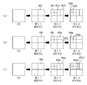
도 5는 본 발명이 적용되는 일 실시예로서, 쿼드 트리 및 바이너리 트리 분할에 기반하여 코딩 블록을 계층적으로 분할하는 일예를 도시한 것이다.FIG. 5 illustrates an example in which a coding block is hierarchically divided based on quad tree and binary tree partitioning according to an embodiment to which the present invention is applied.
도 5에 도시된 바와 같이, 분할 깊이(split depth)가 k인 제1 코딩 블록 300은 쿼드 트리(quad tree)에 기반하여 복수의 제2 코딩 블록으로 분할될 수 있다. 예를 들어, 제2 코딩 블록 310 내지 340은 제1 코딩 블록의 너비와 높이의 절반 크기를 가진 정방형 블록이며, 제2 코딩 블록의 분할 깊이는 k+1로 증가될 수 있다.As shown in FIG. 5, a
분할 깊이가 k+1인 제2 코딩 블록 310은 분할 깊이가 k+2인 복수의 제3 코딩 블록으로 분할될 수 있다. 제2 코딩 블록 310의 분할은 분할 방식에 따라 쿼트 트리 또는 바이너리 트리 중 어느 하나를 선택적으로 이용하여 수행될 수 있다. 여기서, 분할 방식은 쿼드 트리 기반으로의 분할을 지시하는 정보 또는 바이너리 트리 기반의 분할을 지시하는 정보 중 적어도 하나에 기초하여 결정될 수 있다.The
제2 코딩 블록 310이 쿼트 트리 기반으로 분할되는 경우, 제2 코딩 블록 310은 제2 코딩 블록의 너비와 높이의 절반 크기를 가진 4개의 제3 코딩 블록 310a으로 분할되며, 제3 코딩 블록 310a의 분할 깊이는 k+2로 증가될 수 있다. 반면, 제2 코딩 블록 310이 바이너리 트리 기반으로 분할되는 경우, 제2 코딩 블록 310은 2개의 제3 코딩 블록으로 분할될 수 있다. 이때, 2개의 제3 코딩 블록 각각은 제2 코딩 블록의 너비와 높이 중 어느 하나가 절반 크기인 비정방형 블록이며, 분할 깊이는 k+2로 증가될 수 있다. 제2 코딩 블록은 분할 방향에 따라 가로 방향 또는 세로 방향의 비정방형 블록으로 결정될 수 있고, 분할 방향은 바이너리 트리 기반의 분할이 세로 방향인지 또는 가로 방향인지에 관한 정보에 기초하여 결정될 수 있다.When the
한편, 제2 코딩 블록 310은 쿼드 트리 또는 바이너리 트리에 기반하여 더 이상 분할되지 않는 말단 코딩 블록으로 결정될 수도 있고, 이 경우 해당 코딩 블록은 예측 블록 또는 변환 블록으로 이용될 수 있다.Meanwhile, the
제3 코딩 블록 310a은 제2 코딩 블록 310의 분할과 마찬가지로 말단 코딩 블록으로 결정되거나, 쿼드 트리 또는 바이너리 트리에 기반하여 추가적으로 분할될 수 있다. The
한편, 바이너리 트리 기반으로 분할된 제3 코딩 블록 310b은 추가적으로 바이너리 트리에 기반하여 세로 방향의 코딩 블록(310b-2) 또는 가로 방향의 코딩 블록(310b-3)으로 더 분할될 수도 있고, 해당 코딩 블록의 분할 깊이는 k+3으로 증가될 수 있다. 또는, 제3 코딩 블록 310b는 바이너리 트리에 기반하여 더 이상 분할되지 않는 말단 코딩 블록(310b-1)으로 결정될 수 있고, 이 경우 해당 코딩 블록(310b-1)은 예측 블록 또는 변환 블록으로 이용될 수 있다. 다만, 상술한 분할 과정은 쿼드 트리 기반의 분할이 허용되는 코딩 블록의 크기/깊이에 관한 정보, 바이너리 트리 기반의 분할이 허용되는 코딩 블록의 크기/깊이에 대한 정보 또는 바이너리 트리 기반의 분할이 허용되지 않는 코딩 블록의 크기/깊이에 대한 정보 중 적어도 하나에 기초하여 제한적으로 수행될 수 있다.The
코딩 블록이 가질 수 있는 크기는 소정 개수로 제한되거나, 소정 단위 내 코딩 블록의 크기는 고정된 값을 가질 수도 있다. 일 예로, 시퀀스 내 코딩 블록의 크기 또는 픽처 내 코딩 블록의 크기는, 256x256, 128x128 또는 32x32로 제한될 수 있다. 시퀀스 또는 픽처 내 코딩 블록의 크기를 나타내는 정보가 시퀀스 헤더 또는 픽처 헤더를 통해 시그널링 될 수 있다. The size that the coding block can have is limited to a predetermined number, or the size of the coding block in a predetermined unit may have a fixed value. As an example, the size of a coding block in a sequence or the size of a coding block in a picture may be limited to 256x256, 128x128, or 32x32. Information indicating the size of a sequence or an intra-picture coding block may be signaled through a sequence header or a picture header.
쿼드 트리 및 바이너리 트리에 기반한 분할 결과, 코딩 유닛은, 정방형 또는 임의 크기의 직사각형을 띨 수 있다.As a result of the division based on the quadtree and the binary tree, the coding unit may take the form of a square or a rectangle of any size.
도 6은 본 발명이 적용되는 일 실시예로서, 쿼드 트리 및 대칭형 바이너리 트리 분할에 기반하여 코딩 블록을 계층적으로 분할하는 일예를 도시한 것이다.FIG. 6 illustrates an example of hierarchically dividing a coding block based on quad tree and symmetric binary tree partitioning according to an embodiment of the present invention. Referring to FIG.
도 6은 특정 형태, 예를 들어 대칭형 바이너리 트리 기반의 분할만이 허용된 예를 나타낸 도면이다. 도 6의 (a)는 Nx2N 형태의 바이너리 트리 기반의 분할만이 허용되도록 제한된 예를 나타낸다. 예를 들어, 뎁스 1 코딩 블록 601은 뎁스 2에서 2개의 Nx2N 블록 (601a, 601b)으로 분할되고, 또한, 뎁스 2 코딩 블록 602는 뎁스 3에서 2개의 Nx2N 블록 (602a, 602b)로 분할 가능하다. Fig. 6 is a diagram showing an example in which only a specific form, for example, a symmetric binary tree-based partition is allowed. 6 (a) shows an example in which only binary tree-based partitioning in the form of Nx2N is allowed to be permitted. For example, the
도 6의 (b)는 2NxN 형태의 바이너리 트리 기반의 분할만이 허용되도록 제한된 예를 나타낸다. 예를 들어, 뎁스 1 코딩 블록 603은 뎁스 2에서 2개의 2NxN 블록 (603a, 603b)으로 분할되고, 또한, 뎁스 2 코딩 블록 604는 뎁스 3에서 2개의 2NxN 블록 (604a, 604b)로 분할 가능하다.FIG. 6B shows an example in which only a 2NxN type binary tree-based partition is allowed to be allowed. For example, the
도 6의 (c)는 대칭형 바이너리 트리로 분할된 블록을 다시 대칭형 바이너리 트리로 분할하는 예를 나타낸다. 예를 들어, 뎁스 1 코딩 블록 605는, 뎁스 2에서 2개의 Nx2N 블록 (605a, 605b)으로 분할되고, 또한, 상기 분할후 생성된 뎁스 2 코딩 블록 605a는 뎁스 3에서 2개의 Nx2N 블록 (605a1, 605a2)로 분할 가능하다. 상기 분할 방식은 대칭형 바이너리 트리 분할에 의해 생성된 2NxN 코딩 블록에 대해서도 동일하게 적용 가능하다. FIG. 6C shows an example of dividing a block divided into a symmetric binary tree into a symmetric binary tree. For example, the
상기 쿼드 트리 또는 바이너리 트리 기반의 적응적 분할을 구현하기 위해 쿼드 트리 기반의 분할을 지시하는 정보, 쿼드 트리 기반의 분할이 허용되는 코딩 블록의 크기/깊이에 관한 정보, 바이너리 트리 기반의 분할을 지시하는 정보, 바이너리 트리 기반의 분할이 허용되는 코딩 블록의 크기/깊이에 대한 정보, 바이너리 트리 기반의 분할이 허용되지 않는 코딩 블록의 크기/깊이에 대한 정보 또는 바이너리 트리 기반의 분할이 세로 방향인지 또는 가로 방향인지에 관한 정보 등이 이용될 수 있다. 일 예로, quad_split_flag는 코딩 블록이 4개의 코딩 블록으로 분할되는지 여부를 나타내고, binary_split_flag는 코딩 블록이 2개의 코딩 블록으로 분할되는지 여부를 나타낼 수 있다. 코딩 블록이 2개의 코딩 블록으로 분할되는 경우, 코딩 블록의 분할 방향이 수직 방향인지 또는 수평 방향인지 여부를 나타내는 is_hor_split_flag가 시그널링될 수 있다.In order to implement the adaptive partitioning based on the quadtree or the binary tree, information indicating quad tree-based partitioning, information on the size / depth of the quadtree based partitioning allowable coding block, Information about the size / depth of a coding block in which binary tree-based partitioning is allowed, information on the size / depth of a coding block in which binary tree-based partitioning is not allowed, or whether the binary tree- Information regarding the horizontal direction, and the like can be used. In one example, quad_split_flag indicates whether the coding block is divided into four coding blocks, and binary_split_flag indicates whether the coding block is divided into two coding blocks. When the coding block is divided into two coding blocks, is_hor_split_flag indicating whether the division direction of the coding block is the vertical direction or the horizontal direction can be signaled.
또한, 코딩 트리 유닛 또는 소정의 코딩 유닛에 대해, 바이너리 트리 분할이 허용되는 횟수, 바이너리 트리 분할이 허용되는 깊이 또는 바이너리 트리 분할이 허용된 뎁스의 개수 등이 획득될 수 있다. 상기 정보는 코딩 트리 유닛 또는 코딩 유닛 단위로 부호화되어, 비트스트림을 통해 복호화기로 전송될 수 있다.Also, for the coding tree unit or the predetermined coding unit, the number of times the binary tree division is permitted, the depth at which the binary tree division is allowed, or the number of the depths at which the binary tree division is permitted can be obtained. The information may be encoded in units of a coding tree unit or a coding unit, and may be transmitted to a decoder through a bitstream.
일 예로, 비트스트림을 통해, 바이너리 트리 분할이 허용되는 최대 뎁스를 나타내는 신택스 'max_binary_depth_idx_minus1'가 비트스트림을 통해 부호화/복호화될 수 있다. 이 경우, max_binary_depth_idx_minus1+1이 바이너리 트리 분할이 허용되는 최대 뎁스를 가리킬 수 있다.For example, a syntax 'max_binary_depth_idx_minus1' indicating the maximum depth at which binary tree segmentation is allowed may be encoded / decoded through a bitstream, via a bitstream. In this case, max_binary_depth_idx_minus1 + 1 may indicate the maximum depth at which the binary tree division is allowed.
또한, 전술한 도 6 (c) 예를 살펴보면, 뎁스 2인 코딩 유닛 (예, 605a, 605b) 및 뎁스 3인 코딩 유닛 (예, 605a1, 605a2)에 대해 바이너리 트리 분할이 수행된 결과가 도시되었다. 이에 따라, 코딩 트리 유닛 내 바이너리 트리 분할이 수행된 횟수(예, 2회)를 나타내는 정보, 코딩 트리 유닛 내 바이너리 트리 분할이 허용된 최대 뎁스(예, 뎁스 3)를 나타내는 정보 또는 코딩 트리 유닛 내 바이너리 트리 분할이 허용된 뎁스의 개수(예, 2개, 뎁스 2 및 뎁스 3)를 나타내는 정보 중 적어도 하나가 비트스트림을 통해 부호화/복호화될 수 있다.6C, the results of performing the binary tree division on the
다른 예로, 바이너리 트리 분할이 허용되는 횟수, 바이너리 트리 분할이 허용되는 깊이 또는 바이너리 트리 분할이 허용된 뎁스의 개수 중 적어도 하나는 시퀀스, 슬라이스별로 획득될 수 있다. 일 예로, 상기 정보는, 시퀀스, 픽처 또는 슬라이스 단위로 부호화되어 비트스트림을 통해 전송될 수 있다. 이에 따라, 제1 슬라이스 및 제2 슬라이스의, 바이너리 트리 분할 횟수, 바이너리 트리 분할이 허용되는 최대 뎁스 또는 바이너리 트리 분할이 허용되는 뎁스의 개수 중 적어도 하나가 상이할 수 있다. 일 예로, 제1 슬라이스에서는, 하나의 뎁스에서만 바이너리 트리 분할이 허용되는 반면, 제2 슬라이스에서는, 두개의 뎁스에서 바이너리 트리 분할이 허용될 수 있다. As another example, at least one of the number of times the binary tree partition is allowed, the depth at which the binary tree partition is allowed, or the number of the depths at which the binary tree partition is allowed is obtained for each sequence and slice. For example, the information may be encoded in a sequence, picture, or slice unit and transmitted through a bitstream. Accordingly, the first slice and the second slice may differ in at least one of the number of times the binary tree is divided, the maximum depth allowed for binary tree division, or the number of depths allowed for binary tree division. In one example, in the first slice, binary tree segmentation is allowed in only one depth, while in the second slice, binary tree segmentation in two depths is allowed.
또 다른 일 예로, 슬라이스 또는 픽쳐의 시간레벨 식별자(Temporal_ID)에 따라 바이너리 트리 분할이 허용되는 횟수, 바이너리 트리 분할이 허용되는 깊이 또는 바이너리 트리 분할이 허용되는 뎁스의 개수 중 적어도 하나를 상이하게 설정할 수도 있다. 여기서, 시간레벨 식별자(Temporal_ID)는, 시점(view), 공간(spatial), 시간(temporal) 또는 화질(quality) 중 적어도 하나 이상의 스케일러빌리티(Scalability)를 갖는 영상의 복수개의 레이어 각각을 식별하기 위한 것이다.As another example, it is also possible to set at least one of the number of times the binary tree division is permitted, the depth at which the binary tree division is permitted, or the number of the depths at which the binary tree division is allowed, depending on the time level identifier (Temporal_ID) have. Here, the temporal level identifier (Temporal_ID) is used to identify each of a plurality of layers of an image having a scalability of at least one of view, spatial, temporal or image quality will be.
또한, 바이너리 파티셔닝으로 파티션된 CU에서는 Transform skip을 사용하지 않도록 제한할 수도 있다. 또는 비 정방형으로 파티션된 CU에서는 수평 방향 또는 수직 방향 중 적어도 어느 하나의 방향에서만 transformskip을 적용할 수도 있다. 수평방향 transform skip만 적용하는 것은, 수평 방향으로 transform 수행없이 스케일링과 양자화만 수행하고, 수직 방향으로 DCT 나 DST 등 적어도 어느 하나의 transform을 특정하여 변환을 수행하는 것을 나타낸다. You can also limit the use of Transform skip in partitioned CUs with binary partitioning. Alternatively, in a non-square partitioned CU, a transformskip may be applied only in at least one of a horizontal direction and a vertical direction. Applying only the horizontal direction transform skip indicates that only the scaling and the quantization are performed without transforming in the horizontal direction and the transform is performed by specifying at least one transform such as DCT or DST in the vertical direction.
이와 마찬가지로, 수직방향 transform skip만 적용하는 것은 수평 방향으로 DCT 나 DST 등 적어도 어느 하나의 transform을 특정하여 변환을 수행하고, 수직 방향으로 transform 수행없이 스케일링과 양자화만 수행하는 것을 나타낸다. 수평 방향 transform skip을 적용할지를 알려주는 신택스 hor_transform_skip_flag과 수직 방향 transform skip을 적용 여부를 알려주는 신택스 ver_transform_skip_flag을 시그날링할 수도 있다. Likewise, applying only the vertical direction transform skip indicates that at least one transform such as DCT or DST is specified in the horizontal direction to perform the transform, and only the scaling and the quantization are performed without the transform in the vertical direction. It is also possible to signal the syntax hor_transform_skip_flag indicating whether to apply the horizontal direction transform skip and the syntax ver_transform_skip_flag indicating whether the vertical direction transform skip is applied or not.
수평방향 또는 수직방향 중 적어도 어느 하나에 transform skip을 적용할 때, CU의 형태에 따라 어느 방향으로 transform skip을 적용할 지를 시그날링 할 수도 있다.구체적으로 예를 들어, 2NxN 형태의 CU인 경우에 수평 방향으로 transform을 수행하고 수직 방향으로 transform skip을 적용할 수도 있으며, Nx2N 형태의 CU인 경우에 수평 방향으로 transform skip을 적용하고 수직 방향을 transform을 수행할 수도 있다. 여기서 transform은 DCT 또는 DST 중 적어도 어느 하나일 수 있다.When a transform skip is applied to at least one of the horizontal direction and the vertical direction, it may be signaled in which direction the transform skip is applied according to the shape of the CU. Specifically, for example, in the case of a 2NxN type CU Transform can be applied in the horizontal direction and transform skip can be applied in the vertical direction. In case of Nx2N type CU, transform skip can be applied in the horizontal direction and transform can be performed in the vertical direction. Where transform may be at least one of DCT or DST.
또 다른 예를 들어, 2NxN 형태의 CU인 경우에 수직 방향으로 transform을 수행하고 수평 방향으로 transform skip을 적용할 수도 있으며, Nx2N 형태의 CU인 경우에 수직 방향으로 transform skip을 적용하고 수평 방향을 transform을 수행할 수도 있다. 여기서 transform은 DCT 또는 DST 중 적어도 어느 하나일 수 있다.As another example, in case of 2NxN type CU, the transform may be performed in the vertical direction and the transform skip may be applied in the horizontal direction. In the case of the Nx2N type CU, the transform skip is applied in the vertical direction, . ≪ / RTI > Where transform may be at least one of DCT or DST.
도 7은 본 발명이 적용되는 일 실시예로서, 비대칭형 바이너리 트리 분할이 허용되는 파티션 형태를 나타낸 도면이다.2Nx2N 코딩 블록은 너비 비가 n:(1-n)인 2개의 코딩 블록 또는 높이 비가 n:(1-n)인 2개의 코딩 블록으로 분할될 수 있다. 여기서, n은 0보다 크고 1보다 작은 실수를 나타낼 수 있다. Fig. 7 is a diagram showing a partition type in which asymmetric binary tree segmentation is permitted according to an embodiment to which the present invention is applied. A 2Nx2N coding block has two coding blocks whose width ratios are n: (1-n) : (1-n). ≪ / RTI > Where n may represent a real number greater than zero and less than one.
도 7에서는, 예를 들어 코딩 블록에 비대칭 바이너리 트리 파티셔닝이 적용됨에 따라, 너비 비가 1:3 인 2개의 코딩 블록 (701, 702), 또는 3:1인 2개의 코딩 블록 (703, 704), 또는 높이 비가 1:3 인 2개의 코딩 블록 (705, 706) 또는 3:1인 2개의 코딩 블록(707, 708)이 생성되는 것으로 도시되었다.7, two
구체적으로, WxH 크기의 코딩 블록이 수직 방향으로 분할됨에 따라, 너비가 1/4W인 좌측 파티션 및 너비가 3/4W인 우측 파티션이 생성될 수 있다. 위와 같이, 좌측 파티션의 너비가 우측 파티션의 너비보다 작은 분할 형태를 nLx2N 바이너리 파티션이라 호칭할 수 있다.Specifically, as the WxH sized coding block is divided in the vertical direction, a left partition with a width of 1 / 4W and a right partition with a width of 3 / 4W can be created. As mentioned above, the partition type in which the width of the left partition is smaller than the width of the right partition can be referred to as an nLx2N binary partition.
WxH 크기의 코딩 블록이 수직 방향으로 분할됨에 따라, 너비가 3/4W인 좌측 파티션 및 너비가 1/4W인 우측 파티션이 생성될 수도 있다. 위와 같이, 우측 파티션의 너비가 좌측 파티션의 너비보다 작은 분할 형태를 nRx2N 바이너리 파티션이라 호칭할 수 있다. As the WxH sized coding block is divided vertically, a left partition with a width of 3 / 4W and a right partition with a width of 1 / 4W may be created. As described above, the partition type in which the width of the right partition is smaller than the width of the left partition can be referred to as an nRx2N binary partition.
WxH 크기의 코딩 블록이 수평 방향으로 분할됨에 따라, 높이가 1/4H인 상단 파티션 및 높이가 3/4H인 하단 파티션이 생성될 수 있다. 위와 같이, 상단 파티션의 높이가 하단 파티션의 높이보다 작은 분할 형태를 2NxnU 바이너리 파티션이라 호칭할 수 있다. As the WxH sized coding block is divided horizontally, an upper partition with a height of 1 / 4H and a lower partition with a height of 3 / 4H can be created. As described above, the partition type in which the height of the upper partition is smaller than the height of the lower partition can be called a 2NxnU binary partition.
WxH 크기의 코딩 블록이 수평 방향으로 분할됨에 따라, 높이가 3/4H인 상단 파티션 및 높이가 1/4H인 하단 파티션이 생성될 수 있다. 위와 같이, 하단 파티션의 높이가 상단 파티션의 높이보다 작은 분할 형태를 2NxnD 바이너리 파티션이라 호칭할 수 있다.As the WxH sized coding block is divided horizontally, an upper partition with a height of 3 / 4H and a lower partition with a height of 1 / 4H can be created. As described above, the partition type in which the height of the lower partition is smaller than the height of the upper partition can be called a 2NxnD binary partition.
도 7에서는 두 코딩 블록간의 너비 비 또는 높이 비가 1:3 또는 3:1인 경우를 예시하였으나, 비대칭 바이너리 트리 파티셔닝에 의해 생성되는 두 코딩 블록 간 너비 비 또는 높이 비가 이에 한정되는 것은 아니다. 코딩 블록은 도 7에 도시된 것과 상이한 너비 비 또는 상이한 높이 비를 갖는 2개의 코딩 블록으로 분할될 수도 있다.In FIG. 7, a width ratio or a height ratio between two coding blocks is 1: 3 or 3: 1. However, the width ratio or height ratio between two coding blocks generated by asymmetric binary tree partitioning is not limited thereto. The coding block may be divided into two coding blocks having different width ratios or different height ratios from those shown in Fig.
비대칭 바이너리 트리 파티셔닝을 이용하는 경우, 코딩 블록의 비대칭 바이너리 파티션 형태는 비트스트림을 통해 시그널링되는 정보에 기초하여 결정될 수 있다.일 예로, 코딩 블록의 분할 형태는 코딩 블록의 분할 방향을 나타내는 정보 및 코딩 블록이 분할됨에 따라 생성되는 제1 파티션이 제2 파티션보다 작은 크기를 갖는지 여부를 나타내는 정보를 기초로 결정될 수 있다.In the case of using asymmetric binary tree partitioning, the asymmetric binary partition type of the coding block may be determined based on information to be signaled through the bitstream. In one example, the division type of the coding block includes information indicating the dividing direction of the coding block, May be determined based on information indicating whether the first partition to be created has a smaller size than the second partition.
코딩 블록의 분할 방향을 나타내는 정보는, 코딩 블록이 수직 방향으로 분할되었는지 또는 수평 방향으로 분할되었는지 여부를 나타내는 1비트의 플래그일 수 있다. 일 예로, hor_binary_flag 는 코딩 블록이 수평 방향으로 분할되었는지 여부를 나타낼 수 있다. hor_binary_flag의 값이 1인 것은, 코딩 블록이 수평 방향으로 분할됨을 나타내고, hor_binary_flag의 값이 0인 것은, 코딩 블록이 수직 방향으로 분할됨을 나타낼 수 있다. 또는 코딩 블록이 수직 방향으로 분할되었는지 여부를 나타내는 ver_binary_flag가 이용될 수도 있다.The information indicating the dividing direction of the coding block may be a one-bit flag indicating whether the coding block is divided vertically or horizontally. In one example, hor_binary_flag may indicate whether the coding block has been divided horizontally. A value of hor_binary_flag of 1 indicates that the coding block is divided in the horizontal direction and a value of hor_binary_flag is 0 can indicate that the coding block is divided in the vertical direction. Or a ver_binary_flag indicating whether or not the coding block is divided in the vertical direction may be used.
제1 파티션이 제2 파티션보다 작은 크기를 갖는지 여부를 나타내는 정보는, 1비트의 플래그일 수 있다. 일 예로, is_left_above_small_part_flag는 코딩 블록이 분할됨에 따라 생성된 좌측 또는 상단 파티션의 크기가 우측 또는 하측 파티션 보다 작은지 여부를 나타낼 수 있다. is_left_above_small_part_flag의 값이 1인 것은 좌측 또는 상단 파티션의 크기가 우측 또는 하단 파티션보다 작은 것을 의미하고, is_left_above_small_part_flag의 값이 0인 것은 좌측 또는 상단 파티션의 크기가 우측 또는 하단 파티션보다 큰 것을 의미할 수 있다. 또는, 우측 또는 하단 파티션의 크기가 좌측 또는 상단 파티션보다 작은지 여부를 나타내는 is_right_bottom_small_part_flag를 사용할 수도 있다.The information indicating whether the first partition has a smaller size than the second partition may be a flag of 1 bit. For example, is_left_above_small_part_flag may indicate whether the size of the left or top partition generated as a coding block is divided is smaller than the right or the lower partition. If the value of is_left_above_small_part_flag is 1, it means that the size of the left or upper partition is smaller than that of the right or lower partition. If the value of is_left_above_small_part_flag is 0, it means that the size of the left or upper partition is larger than that of the right or lower partition. Alternatively, is_right_bottom_small_part_flag may be used to indicate whether the size of the right or bottom partition is smaller than the left or top partition.
또는, 제1 파티션 및 제2 파티션 간의 너비비, 높이비 또는 넓이비를 나타내는 정보를 사용하여 제1 파티션 및 제2 파티션의 크기를 결정할 수도 있다.Alternatively, the size of the first partition and the second partition may be determined using information indicating a width ratio, a height ratio, or a width ratio between the first partition and the second partition.
hor_binary_flag의 값이 0이고, is_left_above_small_part_flag의 값이 1인 것은, nLx2N 바이너리 파티션을 나타내고, hor_binary_flag의 값이 0이고, is_left_above_small_part_flag의 값이 0인 것은, nRx2N 바이너리 파티션을 나타낼 수 있다. 또한, hor_binary_flag의 값이 1이고, is_left_above_small_part_flag의 값이 1인 것은, 2NxnU 바이너리 파티션을 나타내고, hor_binary_flag의 값이 1이고, is_left_above_small_part_flag의 값이 0인 것은 2NxnD 바이너리 파티션을 나타낼 수 있다.a value of hor_binary_flag is 0 and a value of is_left_above_small_part_flag is 1 indicates an nLx2N binary partition, a value of hor_binary_flag is 0, and a value of is_left_above_small_part_flag is 0 can represent an nRx2N binary partition. In addition, a value of hor_binary_flag is 1 and a value of is_left_above_small_part_flag is 1 indicates a 2NxnU binary partition, a value of hor_binary_flag is 1, and a value of is_left_above_small_part_flag is 0 can represent a 2NxnD binary partition.
다른 예로, 코딩 블록의 비대칭 바이너리 파티션 형태는, 코딩 블록의 파티션 형태를 지시하는 인덱스 정보에 의해 결정될 수도 있다. 여기서, 인덱스 정보는 비트스트림을 통해 시그널링되는 정보로, 고정된 길이(즉, 고정된 비트 수)로 부호화될 수도 있고, 가변 길이로 부호화될 수도 있다. 일 예로, 하기 표 1은 비대칭 바이너리 파티션별 파티션 인덱스를 나타낸 것이다.As another example, the asymmetric binary partition type of the coding block may be determined by index information indicating the partition type of the coding block. Here, the index information is information to be signaled through a bitstream, and may be encoded into a fixed length (i.e., a fixed number of bits) or may be encoded into a variable length. As an example, Table 1 below shows the partition index for each asymmetric binary partition.
비대칭 바이너리 트리 파티셔닝은 QTBT 분할 방법에 종속적으로 이용될 수 있다.일 예로, 코딩 블록에 더 이상 쿼드 트리 분할 또는 바이너리 트리 분할이 적용되지 않는 경우, 해당 코딩 블록에 비대칭 바이너리 트리 분할을 적용할 것인지 여부가 결정될 수 있다. 여기서, 코딩 블록에 비대칭 바이너리 트리 분할을 적용할 것인지 여부는 비트스트림을 통해 시그널링되는 정보에 의해 결정될 수 있다. 예컨대, 상기 정보는 1비트의 플래그 'asymmetric_binary_tree_flag'일 수 있고, 상기 플래그에 기초하여, 코딩 블록에 비대칭 바이너리 트리 분할이 적용되는지 여부가 결정될 수 있다.또는, 코딩 블록이 2개의 블록으로 분할되는 것으로 결정되는 경우, 그 분할 형태가 바이너리 트리 분할인지 또는 비대칭 바이너리 트리 분할인지 여부가 결정될 수도 있다. 여기서, 코딩 블록의 분할 형태가 바이너리 트리 분할인지 또는 비대칭 바이너리 트리 분할인지 여부는 비트스트림을 통해 시그널링되는 정보에 의해 결정될 수 있다. 예컨대, 상기 정보는 1비트의 플래그 'is_asymmetric_split_flag'일 수 있고, 상기 플래그에 기초하여, 코딩 블록이 대칭 또는 비대칭 형태로 분할되는지 여부가 결정될 수 있다.Asymmetric binary tree partitioning can be used depending on the QTBT partitioning method. For example, if no quadtree partitioning or binary tree partitioning is applied to a coding block, then an asymmetric binary tree partitioning is applied to the corresponding coding block Can be determined. Here, whether or not to apply the asymmetric binary tree division to the coding block can be determined by the information signaled through the bitstream. For example, the information may be a one-bit flag 'asymmetric_binary_tree_flag', and based on the flag, it may be determined whether asymmetric binary tree partitioning is applied to the coded block, or the coding block is divided into two blocks If so, it may be determined whether the partition type is a binary tree partition or an asymmetric binary tree partition. Here, whether the division type of the coding block is the binary tree division or the asymmetric binary tree division can be determined by the information signaled through the bit stream. For example, the information may be a one-bit flag 'is_asymmetric_split_flag', and based on the flag, it may be determined whether the coding block is divided into symmetric or asymmetric forms.
다른 예로, 대칭형 바이너리 파티션 및 비대칭형 바이너리 파티션에 서로 다른 인덱스를 할당하고, 인덱스 정보에 따라, 코딩 블록이 대칭 형태 또는 비대칭 형태로 분할되는지 여부를 결정할 수도 있다. 일 예로, 표 2는 대칭형 바이너리 파티션 및 비대칭형 바이너리 파티션에 각기 다른 인덱스가 할당된 예를 나타낸 것이다.As another example, different indexes may be assigned to symmetrical binary partitions and asymmetric binary partitions and, depending on the index information, determine whether the coding block is divided into symmetric or asymmetric forms. As an example, Table 2 shows an example in which different indexes are assigned to symmetric binary partitions and asymmetric binary partitions.
코딩 트리 블록 또는 코딩 블록은, 쿼드 트리 분할, 바이너리 트리 분할 또는 비대칭 바이너리 트리 분할을 통해 복수의 코딩 블록으로 세분화될 수 있다. 일 예로, 도 8은 QTBT 및 비대칭 바이너리 트리 분할을 이용하여 코딩 블록이 복수의 코딩 블록으로 분할되는 예를 나타낸 도면이다. 도 9를 참조하면, 첫번째 그립의 뎁스 2 파티셔닝, 두번째 그림의 뎁스 3 파티셔닝, 세번째 그림의 뎁스 3 파티셔닝에서 각각 비대칭 바이너리 트리 분할이 수행된 것을 확인할 수 있다.비대칭 바이너리 트리 파티셔닝을 통해 분할된 코딩 블록은 더 이상 분할되지 않도록 제한될 수 있다. 일 예로, 비대칭 바이너리 트리 파티셔닝을 통해 생성된 코딩 블록에는 쿼드 트리, 바이너리 트리 또는 비대칭 바이너리 트리 관련 정보가 부호화/복호화되지 않을 수 있다. 즉, 비대칭 바이너리 트리 파티셔닝을 통해 생성된 코딩 블록에 대해서는, 쿼드 트리 분할 여부를 나타내는 플래그, 바이너리 트리 분할 여부를 타나내는 플래그, 비대칭 바이너리 트리 분할 여부를 나타내는 플래그, 바이너리 트리 또는 비대칭 바이너리 트리 분할 방향을 나타내는 플래그, 또는 비대칭 바이너리 파티션을 나타내는 인덱스 정보 등의 신택스의 부호화/복호화가 생략될 수 있다.The coding tree block or coding block may be subdivided into a plurality of coding blocks by quad tree partitioning, binary tree partitioning, or asymmetric binary tree partitioning. For example, FIG. 8 shows an example in which a coding block is divided into a plurality of coding blocks using QTBT and asymmetric binary tree partitioning. Referring to FIG. 9, it can be seen that the asymmetric binary tree partitioning is performed in the
다른 예로, 바이너리 트리 파티셔닝을 허용할 것인지 여부는 QTBT의 허용 여부에 종속적으로 결정될 수 있다. 일 예로, QTBT에 기초한 분할 방법이 사용되지 않는 픽쳐 또는 슬라이스에서는 비대칭 바이너리 트리 파티셔닝이 사용되지 않도록 제한될 수 있다.As another example, whether or not to allow binary tree partitioning can be determined depending on whether the QTBT is allowed or not. As an example, in a picture or slice in which a QTBT-based partitioning method is not used, asymmetric binary tree partitioning may be restricted from being used.
비대칭 바이너리 트리 파티셔닝이 허용되는지 여부를 나타내는 정보가 블록 단위, 슬라이스 단위 또는 픽처 단위로 부호화되어 시그널링될 수도 있다. 여기서, 비대칭 바이너리 트리 파티셔닝이 허용되는지 여부를 나타내는 정보는 1비트의 플래그일 수 있다. 일 예로, is_used_asymmetric_QTBT_enabled_flag의 값이 0인 것은, 비대칭 바이너리 트리 파티셔닝이 사용되지 않음을 나타낼 수 있다. 픽처 단위 또는 슬라이스 단위로 바이너리 트리 파티셔닝이 사용되지 않는 경우, is_used_asymmetric_QTBT_enabled_flag를 시그널링하지 않고, 그 값을 0으로 설정할 수도 있다.Information indicating whether asymmetric binary tree partitioning is allowed may be coded and signaled on a block basis, a slice basis or a picture basis. Here, the information indicating whether asymmetric binary tree partitioning is permitted may be a one-bit flag. As an example, a value of is_used_asymmetric_QTBT_enabled_flag of 0 may indicate that asymmetric binary tree partitioning is not used. If binary tree partitioning is not used in picture units or slice units, it may be set to 0 without signaling is_used_asymmetric_QTBT_enabled_flag.
도 8은 본 발명이 적용되는 일 실시예로서, 쿼드 트리 및 대칭형/비대칭형 바이너리 트리 분할에 기반한 코딩 블록의 분할 형태를 예시한 것이다.FIG. 8 illustrates an embodiment of the present invention to which a coding block is divided based on a quadtree and a symmetric / asymmetric binary tree division.
도 8의 (a)는 nLx2N 형태의 비대칭형 바이너리 트리 기반의 분할이 허용된 예를 나타낸다. 예를 들어, 뎁스 1 코딩 블록 801은 뎁스 2에서 비대칭형 2개의 nLx2N 블록 (801a, 801b)으로 분할되고, 또한, 뎁스 2 코딩 블록 801b는 뎁스 3에서 대칭형 2개의 Nx2N 블록 (801b1, 801b2)로 분할된 예를 도시한 것이다. Fig. 8A shows an example in which asymmetric binary tree-based partitioning of nLx2N type is allowed. For example, the
도 8의 (b)는, nRx2N 형태의 비대칭형 바이너리 트리 기반의 분할이 허용된 예를 나타낸다. 예를 들어, 뎁스 2 코딩 블록 802는 뎁스 3에서 비대칭형 2개의 nRx2N 블록 (802a, 802b)으로 분할된 예를 도시한 것이다.Fig. 8 (b) shows an example in which asymmetric binary tree-based partitioning of nRx2N type is permitted. For example, the
도 8의 (c)는 2NxnU 형태의 비대칭형 바이너리 트리 기반의 분할이 허용된 예를 나타낸다. 예를 들어, 뎁스 2 코딩 블록 803은 뎁스 3에서 비대칭형 2개의 2NxnU 블록 (803a, 803b)으로 분할된 예를 도시한 것이다.FIG. 8 (c) shows an example in which an asymmetric binary tree-based partition of 2NxnU type is allowed. For example, the
코딩 블록의 크기, 형태, 분할 깊이 또는 분할 형태 등에 기초하여, 코딩 블록에 허용되는 분할 형태가 결정될 수도 있다. 일 예로, 쿼드 트리 분할에 의해 생성된 코딩 블록 및 바이너리 트리 분할에 의해 생성된 코딩 블록 사이 허용되는 분할 타입, 파티션 형태 또는 파티션 개수 중 적어도 하나는 상이할 수 있다.Based on the size, type, division depth, or division type of the coding block, the type of division allowed in the coding block may be determined. In one example, at least one of the partition types, partition types or number of partitions allowed between the coding blocks generated by the quadtree partitioning and the coding blocks generated by the binary tree partitioning may be different.
일 예로, 코딩 블록이 쿼드 트리 분할에 의해 생성된 것일 경우, 해당 코딩 블록에는, 쿼드 트리 분할, 바이너리 트리 분할 및 비대칭 바이너리 트리 분할 모두 허용될 수 있다. 즉, 코딩 블록이 쿼드 트리 분할에 기초하여 생성된 것일 경우, 코딩 블록에는 도 10에 나타난 모든 파티션 형태가 적용될 수 있다.일 예로, 2Nx2N 파티션은 코딩 블록이 더 이상 분할되지 않는 경우를 나타내고, NxN은 코딩 블록이 쿼드트리 분할되는 경우를 나타내며, Nx2N 및 2NxN은 코딩 블록이 바이너리 트리 분할되는 경우를 나타낼 수 있다. 또한, nLx2N, nRx2N, 2NxnU 및 2NxnD는 코딩 블록이 비대칭 바이너리 트리 분할되는 경우를 나타낼 수 있다.For example, if the coding block is generated by quadtree partitioning, quadtree partitioning, binary tree partitioning, and asymmetric binary tree partitioning may all be allowed in the corresponding coding block. That is, if the coding block is generated based on quad tree partitioning, the coding block can be applied to all partition types shown in Figure 10. For example, a 2Nx2N partition indicates a case where the coding block is not further divided, and NxN Represents a case where a coding block is quad-tree divided, and Nx2N and 2NxN may represent a case where a coding block is divided into a binary tree. Further, nLx2N, nRx2N, 2NxnU, and 2NxnD may represent cases where a coding block is divided into asymmetric binary trees.
반면, 코딩 블록이 바이너리 트리 분할에 의해 생성된 것일 경우, 해당 코딩 블록에는 비대칭 바이너리 트리 분할을 제한할 수 있다. 즉, 코딩 블록이 바이너리 트리 분할에 기초하여 생성된 것일 경우, 코딩 블록에는 도 7에 도시된 파티션 형태들 중 비대칭 파티션 형태(nLx2N, nRx2N, 2NxnU, 2NxnD)을 적용하는 것이 제한될 수 있다.On the other hand, when the coding block is generated by the binary tree division, it is possible to restrict the asymmetric binary tree division to the corresponding coding block. That is, if the coding block is generated based on the binary tree partitioning, applying the asymmetric partition type (nLx2N, nRx2N, 2NxnU, 2NxnD) among the partition types shown in Fig. 7 to the coding block can be restricted.
도 9는 본 발명이 적용되는 일 실시예로서, 쿼드 트리 및 바이너리 트리 분할에 기반한 코딩 블록 분할 방법에 대한 흐름도이다.9 is a flowchart illustrating a method of dividing a coding block based on quad tree and binary tree partitioning according to an embodiment of the present invention.
뎁스 k 코딩 블록을, 뎁스 k+1 코딩 블록으로 분할하는 것으로 가정한다. 우선, 뎁스 k 현재 블록에 쿼드 트리 분할이 적용되는 지를 판단한다(S910). 만약 쿼드 트리 분할이 적용되었다면, 현재 블록을 4개의 정방형 블록으로 분할한다(S920). 반면, 만약 쿼드 트리 분할이 적용되지 않았다면, 현재 블록에 바이너리 트리 분할이 적용되는 지를 판단한다(S930). 만약 바이너리 트리 분할도 적용되지 않았다면, 현재 블록은 분할 없이 뎁스 k+1 코딩 블록이 된다. 상기 S930 판단 결과, 현재 블록에 바이너리 트리 분할이 적용되었다면, 대칭형 바이너리 분할 또는 비대칭형 바이너리 분할 중 어느 방식이 적용되는 지를 확인한다(S940). 상기 S940 판단 결과에 따라, 현재 블록에 적용되는 파티션 형태를 결정한다(S950). 예를 들어, 상기 S950 단계에 적용되는 파티션 형태는, 대칭형인 경우 도 4(b) 형태중 어느 하나, 또는 비대칭형인 경우 도4(c) 형태 중 어느 하나가 될 수 있다. 상기 S950을 통해, 결정된 파티션 형태에 따라, 현재 블록을 2개의 뎁스 k+1 코딩 블록으로 분할하게 된다(S960). Assume that the depth k coding block is divided into depth k + 1 coding blocks. First, it is determined whether quad tree partitioning is applied to the depth k current block (S910). If quad tree partitioning is applied, the current block is divided into four square blocks (S920). On the other hand, if quad tree partitioning is not applied, it is determined whether binary tree partitioning is applied to the current block (S930). If no binary tree partitioning is applied, the current block becomes a depth k + 1 coding block without division. If it is determined in step S930 that the binary tree segmentation is applied to the current block, it is checked whether the symmetric binary segmentation or the asymmetric binary segmentation is applied (S940). In step S950, a partition type to be applied to the current block is determined according to the determination result of step S940. For example, the partition type applied to the step S950 may be any one of the shapes shown in FIG. 4 (b) when it is a symmetric shape, or a shape shown in FIG. 4 (c) when it is an asymmetric shape. In step S950, the current block is divided into two depth k + 1 coding blocks according to the determined partition type (S960).
도 10은 본 발명이 적용되는 일 실시예로서, 쿼드 트리 및 바이너리 트리 분할이 적용되는 네트워크 추상화 계층 (NAL)에 포함되는 신택스 요소(syntax element)를 예를 들어 도시한 것이다.FIG. 10 illustrates an example of a syntax element included in a network abstraction layer (NAL) to which a quadtree and a binary tree are applied, according to an embodiment of the present invention.
본 발명이 적용되는 압축된 영상은, 예를 들어 네트워크 추상화 계층 (Network Abstract Layer, 이하 'NAL' 이라 함) 단위로 패킷화 되어 전송 매체를 통해 전송될 수 있다. 단, 본 발명은 NAL에 한정되지 않으며, 향후 개발될 다양한 데이터 전송 방식에도 적용 가능하다. 본 발명이 적용되는 NAL 유닛은, 예를 들어, 도 10에 도시된 바와 같이 비디오 파라미터 셋 (VPS), 시퀀스 파라미터 셋(SPS), 픽쳐 파라미터 셋(PPS) 및 적어도 하나 이상의 슬라이스 셋(Slice)을 포함할 수 있다. The compressed image to which the present invention is applied can be packetized on a network abstraction layer (NAL) basis, for example, and transmitted through a transmission medium. However, the present invention is not limited to NAL, and can be applied to various data transmission schemes to be developed in the future. The NAL unit to which the present invention is applied includes a video parameter set (VPS), a sequence parameter set (SPS), a picture parameter set (PPS) and at least one slice set (Slice) .
예를 들어, 도 10에서는 시퀀스 파라미터 셋(SPS)에 포함된 신택스 요소를 도시하였으나, 픽쳐 파라미터 셋(PPS) 또는 슬라이스 셋(Slice)에 신택스 요소를 포함하는 것도 가능하다. 또한, 신택스 요소별로 시퀀스 단위 또는 픽쳐 단위에 공통적으로 적용될 신택스 요소는 시퀀스 파라미터 셋(SPS) 또는 픽쳐 파라미터 셋(PPS)에 포함되도록 할 수 있다. 반면, 해당 슬라이스에만 적용되는 신택스 요소는 슬라이스 셋(Slice)에 포함되는 것이 바람직하다. 따라서, 이는 부호화 성능 및 효율을 고려하여 선택이 가능하다. For example, although FIG. 10 shows a syntax element included in a sequence parameter set (SPS), it is also possible to include a syntax element in a picture parameter set (PPS) or a slice set (Slice). In addition, a syntax element to be commonly applied to a sequence unit or a picture unit for each syntax element may be included in a sequence parameter set (SPS) or a picture parameter set (PPS). On the other hand, a syntax element that is applied only to the slice is preferably included in the slice set. Therefore, it can be selected in consideration of coding performance and efficiency.
관련하여, 쿼드 트리 및 바이너리 트리 분할이 적용되는 신택스 요소를 설명하면 다음과 같다. 도 10에 도시된 모든 신택스 요소를 필수 요소로 설정하는 것도 가능하지만, 부호화 효율 및 성능을 고려하여, 이중 신택스 요소를 선택적으로 설정하는 것도 가능하다. With respect to the syntax elements to which the quadtree and binary tree division are applied, the following will be described. Although it is possible to set all the syntax elements shown in FIG. 10 as essential elements, it is also possible to selectively set the double syntax elements in consideration of the coding efficiency and performance.
일 예로, 'quad_split_flag'는 코딩 블록이 4개의 코딩 블록으로 분할되는지 여부를 나타낸다. 'binary_split_flag'는 코딩 블록이 2개의 코딩 블록으로 분할되는지 여부를 나타낼 수 있다. 코딩 블록이 2개의 코딩 블록으로 분할되는 경우, 코딩 블록의 분할 방향이 수직 방향인지 또는 수평 방향인지 여부를 나타내는 'is_hor_split_flag'가 시그널링될 수 있다. “is_hor_split_flag = 1” 이면 수평방향을 “is_hor_split_flag = 0” 이면 수직방향을 나타내는 것으로 정의할 수 있다. For example, 'quad_split_flag' indicates whether the coding block is divided into four coding blocks. 'binary_split_flag' may indicate whether the coding block is divided into two coding blocks. When the coding block is divided into two coding blocks, 'is_hor_split_flag' indicating whether the dividing direction of the coding block is vertical or horizontal can be signaled. If " is_hor_split_flag = 1 ", the horizontal direction is defined as " is_hor_split_flag = 0. "
또한, 다른 대안으로, 'isUseBinaryTreeFlag'를 통해 현재 블록에 바이너리 트리 파티셔닝이 적용 여부를 나타내고, 또한, 코딩 블록의 분할 방향을 나타내는 신택스 요소로서, 'hor_binary_flag' 는 코딩 블록이 수평 방향으로 분할되었는지 여부를 나타낼 수 있다. 예를 들어, “hor_binary_flag = 1”인 경우, 코딩 블록이 수평 방향으로 분할됨을 나타내고, “hor_binary_flag = 0”인 경우, 코딩 블록이 수직 방향으로 분할됨을 나타낼 수 있다. 또는 'hor_binary_flag' 대신 코딩 블록이 수직 방향으로 분할되었는지 여부를 나타내는 ver_binary_flag가 이용하여 동일한 방식으로 설정할 수 있다. As another alternative, 'isUseBinaryTreeFlag' indicates whether binary tree partitioning is applied to the current block. Also, 'hor_binary_flag' indicates whether or not the coding block is divided horizontally as a syntax element indicating the dividing direction of the coding block . For example, "hor_binary_flag = 1" indicates that the coding block is divided in the horizontal direction, and "hor_binary_flag = 0" indicates that the coding block is divided in the vertical direction. Or 'ver_binary_flag' indicating whether or not the coding block is vertically divided instead of 'hor_binary_flag'.
또한, 바이너리 트리 분할이 허용되는 최대 뎁스를 나타내는 신택스 요소로서, 'max_binary_depth_idx_minus1'을 정의할 수 있다. 예를 들어, “max_binary_depth_idx_minus1 + 1”이 바이너리 트리 분할이 허용되는 최대 뎁스를 가리킬 수 있다.In addition, 'max_binary_depth_idx_minus1' can be defined as a syntax element indicating the maximum depth to which the binary tree division is permitted. For example, " max_binary_depth_idx_minus1 + 1 " may indicate the maximum depth at which the binary tree partition is allowed.
또한, 수평 방향 transform skip을 적용할지를 알려주는 신택스 요소로서, 'hor_transform_skip_flag'과 수직 방향 transform skip을 적용 여부를 알려주는 신택스 요소로 'ver_transform_skip_flag'을 설정할 수도 있다.It is also possible to set 'ver_transform_skip_flag' as a syntax element that indicates whether hor_transform_skip_flag and vertical transform skip are applied as a syntax element indicating whether to apply horizontal transform skip.
또한, 비대칭 바이너리 트리 파티셔닝이 허용되는지 여부를 나타내는 신택스 요소로서, 'is_used_asymmetric_QTBT_enabled_flag'을 정의할 수 있다. 예를 들어, “is_used_asymmetric_QTBT_enabled_flag = 1” 이면, 비대칭 바이너리 트리 파티셔닝이 사용되었음을 나타내고, “is_used_asymmetric_QTBT_enabled_flag = 0” 이면, 비대칭 바이너리 트리 파티셔닝이 사용되지 않았음을 나타낼 수 있다. 반면, 픽처 단위 또는 슬라이스 단위로 바이너리 트리 파티셔닝이 사용되지 않는 경우, is_used_asymmetric_QTBT_enabled_flag를 시그널링하지 않고, 그 값을 0으로 설정할 수도 있다. 또한, 다른 대안으로, 'asymmetric_binary_tree_flag'를 통해 현재 블록에 비대칭형 바이너리 트리 파티셔닝이 적용되는 지를 나타낼 수 있다.Also, as a syntax element indicating whether or not asymmetric binary tree partitioning is allowed, 'is_used_asymmetric_QTBT_enabled_flag' can be defined. For example, "is_used_asymmetric_QTBT_enabled_flag = 1" indicates that an asymmetric binary tree partitioning has been used, and "is_used_asymmetric_QTBT_enabled_flag = 0" indicates that asymmetric binary tree partitioning has not been used. On the other hand, if binary tree partitioning is not used on a picture-by-picture or slice-by-slice basis, it may be set to 0 without signaling is_used_asymmetric_QTBT_enabled_flag. Alternatively, asymmetric binary tree partitioning may be applied to the current block via 'asymmetric_binary_tree_flag'.
또한, 비대칭형 바이너리 트리 분할을 나타내는 신택스 요소로서, 'is_left_above_small_part_flag'는 코딩 블록이 분할됨에 따라 생성된 좌측 또는 상단 파티션의 크기가 우측 또는 하측 파티션 보다 작은지 여부를 나타낼 수 있다. 예를 들어, “is_left_above_small_part_flag =1” 인 경우, 좌측 또는 상단 파티션의 크기가 우측 또는 하단 파티션보다 작은 것을 의미하고, “is_left_above_small_part_flag = 0”인 경우, 좌측 또는 상단 파티션의 크기가 우측 또는 하단 파티션보다 큰 것을 의미할 수 있다. 또는, 'is_left_above_small_part_flag' 대신, 우측 또는 하단 파티션의 크기가 좌측 또는 상단 파티션보다 작은지 여부를 나타내는 'is_right_bottom_small_part_flag'를 사용할 수도 있다.Also, 'is_left_above_small_part_flag' may indicate whether the size of the left or upper partition generated as the coding block is divided is smaller than the size of the right or lower partition, as a syntax element indicating an asymmetric binary tree partition. For example, in the case of "is_left_above_small_part_flag = 1", it means that the size of the left or upper partition is smaller than that of the right or lower partition. When "is_left_above_small_part_flag = 0" It can mean something. Alternatively, 'is_right_bottom_small_part_flag' may be used instead of 'is_left_above_small_part_flag' to indicate whether the size of the right or lower partition is smaller than the left or upper partition.
관련하여, 상기 신택스 요소들을 조합하여 코딩 블록의 비대칭형 바이너리 파티션 형태를 정의하는 것이 가능하다. 예를 들어, “hor_binary_flag = 0” 이고“is_left_above_small_part_flag =1” 이면 nLx2N 바이너리 파티션을 나타내고, “hor_binary_flag = 0”이고, “is_left_above_small_part_flag = 0” 이면 nRx2N 바이너리 파티션을 나타내는 것으로 설정할 수 있다. 또한, “hor_binary_flag = 1”이고 “is_left_above_small_part_flag = 1” 이면 2NxnU 바이너리 파티션을 나타내고, “hor_binary_flag = 1”이고 “is_left_above_small_part_flag = 0”이면 2NxnD 바이너리 파티션을 나타낼 수 있다. 마찬가지로, 상기 'ver_binary_flag' 및 'is_right_bottom_small_part_flag'의 조합을 이용하여 비대칭형 바이너리 파티션 형태를 나타낼 수 도 있다. In this regard, it is possible to define the asymmetric binary partition type of the coding block by combining the syntax elements. For example, if "hor_binary_flag = 0" and "is_left_above_small_part_flag = 1", it indicates nLx2N binary partition, and if "hor_binary_flag = 0" and "is_left_above_small_part_flag = 0", it indicates nRx2N binary partition. Further, if "hor_binary_flag = 1" and "is_left_above_small_part_flag = 1", it indicates a 2NxnU binary partition. If "hor_binary_flag = 1" and "is_left_above_small_part_flag = 0", a 2NxnD binary partition can be represented. Similarly, a combination of 'ver_binary_flag' and 'is_right_bottom_small_part_flag' may be used to indicate an asymmetric binary partition type.
또한, 다른 대안으로, Asymetric_partition_index'에 의해 전술한 표 1의 인덱스를 표시하거나, 또는 'Binary_partition_index'에 의해 전술한 표 2의 인덱스를 표시함에 의해, 코딩 블록의 비대칭형 바이너리 파티션 형태를 정의하는 것이 가능하다. Alternatively, it is possible to define the asymmetric binary partition type of the coded block by displaying the index of Table 1 described above by Asymetric_partition_index ', or by displaying the index of Table 2 described above by' Binary_partition_index ' Do.
상술한 예에서 살펴본 바와 같이, 코딩 유닛(또는 코딩 트리 유닛)은 적어도 하나의 수직선 또는 수평선 등에 의해 재귀적으로 분할될 수 있다. 일 예로, 쿼드 트리 분할은, 수평선 및 수직선을 이용하여 코딩 블록을 분할하는 방법이고, 바이너리 트리 분할은, 수평선 또는 수직선을 이용하여 코딩 블록을 분할하는 방법으로 요약될 수 있다. 쿼드 트리 분할 및 바이너리 트리 분할되는 코딩 블록의 파티션 형태는 도 4 내지 도 8에 도시된 예에 한정되지 않으며, 도시된 것 이외의 확장된 파티션 형태가 사용될 수 있다. 즉, 코딩 블록은 도 4 내지 도 8에 도시된 것과 다른 형태로 재귀적으로 분할될 수 있다. As described in the above example, the coding unit (or coding tree unit) can be recursively divided by at least one vertical line or a horizontal line. For example, quad tree partitioning is a method of dividing a coding block using a horizontal line and a vertical line, and a binary tree partitioning can be summarized as a method of dividing a coding block using a horizontal line or a vertical line. The partitioning form of the quad-tree partitioning and the binary tree-partitioning coding block is not limited to the example shown in Figs. 4 to 8, and an extended partitioning form other than the illustrated one can be used. That is, the coding block may be recursively divided in a form different from that shown in Figs.
도 11은 본 발명이 적용되는 다른 실시예로서, 비대칭형 쿼드 트리 분할이 허용되는 파티션 형태를 나타낸 도면이다.FIG. 11 is a diagram illustrating a partition type in which asymmetric quadtree partitioning is allowed according to another embodiment to which the present invention is applied.
현재 블록이 쿼드 트리 분할되는 경우, 수평선 또는 수직선 중 적어도 하나는 코딩 블록을 비대칭 형태로 분할할 수도 있다. 여기서, 비대칭은, 수평선에 의해 분할된 블록들의 높이가 동일하지 않은 경우 또는 수직선에 의해 분할된 블록들의 너비가 동일하지 않은 경우 등을 의미할 수 있다. 일 예로, 수평선은 코딩 블록을 비대칭 형태로 분할함에 반해, 수직선은 코딩 블록을 대칭 형태로 분할할 수도 있고, 수평선은 코딩 블록을 대칭 형태로 분할함에 반해, 수직선은 코딩 블록을 비대칭 형태로 분할할 수도 있다. 또는, 수평선 및 수직선 모두 코딩 블록을 비대칭 형태로 분할할 수도 있다.If the current block is quad-tree partitioned, at least one of the horizontal or vertical lines may divide the coded block into asymmetric forms. Here, the asymmetry may mean that the height of the blocks divided by the horizontal line is not the same or the widths of the blocks divided by the vertical line are not the same. For example, a horizontal line divides a coding block into asymmetrical shapes, while a vertical line divides a coding block into a symmetric shape, while a horizontal line divides a coding block into a symmetrical shape, while a vertical line divides a coding block into an asymmetric shape It is possible. Alternatively, both the horizontal and vertical lines may be divided into asymmetric coded blocks.
도 11 (a)는 코딩 블록의 대칭형 쿼드 트리 분할 형태를 나타내고, (b)~(k)는 코딩 블록의 비대칭형 쿼드 트리 분할 형태를 나타낸 도면이다. 도 11 (a)는 수평선 및 수직선이 모두 대칭형 분할에 이용된 예를 나타낸 것이다. 도 11 (b) 및 (c)는 수평선은 대칭형 분할에 이용된 반면, 수직선은 비대칭형 분할에 이용된 예를 나타낸 것이다. 도 11 (d) 및 (e)는 수직선은 대칭형 분할에 이용된 반면, 수평선은 비대칭형 분할에 이용된 예를 나타낸 것이다.11 (a) shows a symmetric quad tree partitioning type of a coding block, and (b) to (k) are views showing an asymmetric quad tree partitioning type of a coding block. 11 (a) shows an example in which both a horizontal line and a vertical line are used for symmetric division. Figs. 11 (b) and (c) show examples in which the horizontal lines are used for symmetric partitioning, while the vertical lines are used for asymmetric partitioning. 11 (d) and 11 (e) show examples in which the vertical line is used for symmetric partitioning, while the horizontal line is used for asymmetric partitioning.
코딩 블록의 분할 형태를 특정하기 위해, 코딩 블록의 분할 형태와 관련된 정보를 부호화할 수 있다. 여기서, 상기 정보는, 코딩 블록의 분할 형태가 대칭형인지 또는 비대칭형인지를 나타내는 제1 지시자를 포함할 수 있다. 제1 지시자는 블록 단위로 부호화될 수도 있고, 수직선 또는 수평선 별로 부호화될 수 있다. 일 예로, 제1 지시자는 수직선이 대칭 분할에 이용되는지 여부를 나타내는 정보 및 수평선이 대칭 분할에 이용되는지 여부를 나타내는 정보를 포함할 수 있다.In order to specify the division type of the coding block, information related to the division type of the coding block can be encoded. Here, the information may include a first indicator indicating whether the division type of the coding block is symmetric or asymmetric. The first indicator may be coded on a block-by-block basis, or may be coded on a vertical or horizontal line basis. In one example, the first indicator may include information indicating whether a vertical line is used for the symmetric division and information indicating whether a horizontal line is used for the symmetric division.
또는, 상기 제1 지시자는 수직선 또는 수평선 중 적어도 하나에 대해서만 부호화되고, 제1 지시자가 부호화되지 않는 다른 하나의 분할 형태는 제1 지시자에 의해 종속적으로 유도될 수도 있다. 예컨대, 제1 지시자가 부호화되지 않는 다른 하나의 분할 형태는 제1 지시자와 반대의 값을 가질 수 있다. 즉, 제1 지시자가 수직선이 비대칭분할에 이용됨을 나타내는 경우, 수평선은 제1 지시자와 반대인 대칭 분할에 이용되도록 설정될 수 있다.Alternatively, the first indicator may be coded only for at least one of a vertical line and a horizontal line, and another division type for which the first indicator is not encoded may be derived by the first indicator. For example, another division type in which the first indicator is not encoded may have a value opposite to that of the first indicator. That is, if the first indicator indicates that the vertical line is used for asymmetric partitioning, the horizontal line may be set to be used for the symmetric partition opposite to the first indicator.
제1 지시자가 비대칭 분할임을 나타내는 경우, 수직선 또는 수평선에 대해 제2 지시자를 추가 부호화할 수도 있다. 여기서, 제2 지시자는, 비대칭 분할에 이용되는 수직선 또는 수평선의 위치 또는 수직선 또는 수평선에 의해 분할되는 블록 간의 비율 중 적어도 하나를 나타낼 수 있다. If the first indicator indicates an asymmetric partition, the second indicator may be further encoded with respect to the vertical or horizontal line. Here, the second indicator may indicate at least one of a position of a vertical line or a horizontal line used for asymmetric division or a ratio between blocks divided by a vertical line or a horizontal line.
복수의 수직선 또는 복수의 수평선을 이용하여, 쿼드 트리 분할이 수행될 수도 있다. 일 예로, 하나 이상의 수직선 또는 하나 이상의 수평선 중 적어도 하나를 조합함으로써, 코딩 블록을 4개의 블록으로 분할하는 것도 가능하다.Quad tree segmentation may be performed using a plurality of vertical lines or a plurality of horizontal lines. As an example, it is also possible to divide a coding block into four blocks by combining at least one of one or more vertical lines or one or more horizontal lines.
도 11 (f)~(k)는 복수의 수직선/수평선과 하나의 수평선/수직선을 조합함으로써, 코딩 블록을 비대칭적으로 분할하는 예를 나타낸 도면이다. 11 (f) to (k) are views showing an example of asymmetrically dividing a coding block by combining a plurality of vertical lines / horizontal lines and one horizontal line / vertical line.
도 11 (f)~(k)를 참조하면, 쿼드트리 분할은, 두개의 수직선 또는 두개의 수평선에 의해 코딩 블록을 세개의 블록으로 분할하고, 분할된 3개의 블록 중 어느 하나를 2개의 블록으로 분할함으로써 수행될 수 있다. 이때, 도 11 (f)~(k)에 도시된 예에서와 같이, 두개의 수직선 또는 두개의 수평선에 의해 분할된 블록 중 가운데에 위치한 블록이 하나의 수평선 또는 수직선에 의해 분할될 수 있다. 도시된 예에 그치지 않고, 코딩 블록의 일측 경계에 위치한 블록이 하나의 수평선 또는 수직선에 의해 분할될 수도 있다. 또는, 3개의 파티션 중 분할되는 파티션을 특정하기 위한 정보(예컨대, 파티션 인덱스)가 비트스트림을 통해 시그날링될 수도 있다. 11 (f) to (k), quad tree partitioning divides a coding block into three blocks by two vertical lines or two horizontal lines, and divides one of the three divided blocks into two blocks Lt; / RTI > At this time, as in the example shown in Figs. 11 (f) to 11 (k), a block located at the center among the blocks divided by two vertical lines or two horizontal lines can be divided by one horizontal line or a vertical line. In addition to the examples shown, blocks located at one side of a coding block may be divided by one horizontal or vertical line. Alternatively, information (e.g., a partition index) for specifying a partition to be partitioned among the three partitions may be signaled through a bitstream.
수평선 또는 수직선 중 적어도 하나는 코딩 블록을 비대칭 형태로 분할하는데 이용되고, 다른 하나는 코딩 블록을 대칭 형태로 분할하는데 이용될 수 있다. 일 예로, 복수의 수직선 또는 수평선이 코딩 블록을 대칭 형태로 분할하는데 이용되거나, 하나의 수평선 또는 수직선이 코딩 블록을 대칭 형태로 분할하는데 이용될 수 있다. 또는, 수평선 또는 수직선 모두 코딩 블록을 대칭 형태로 분할하는데 이용되거나, 비대칭 형태로 분할하는데 이용될 수도 있다.At least one of a horizontal line or a vertical line may be used to divide the coding block into an asymmetric form, and the other may be used to divide the coding block into a symmetrical form. As an example, a plurality of vertical or horizontal lines may be used to divide the coding block into symmetrical shapes, or one horizontal or vertical line may be used to divide the coding blocks into symmetrical shapes. Alternatively, both horizontal and vertical lines may be used to divide the coding block into symmetrical shapes, or may be used to divide asymmetrically.
예를 들어, 도 11(f)는, 2개 수직선에 의해 비대칭 형태로 분할된 가운데 코딩 블록을 수평선에 의해 2개의 대칭형 코딩 블록으로 분할한 파티션 형태를 도시한 것이다. 또한, 도 11(g)는 2개 수평선에 의해 비대칭 형태로 분할된 가운데 코딩 블록을 수직선에 의해 2개의 대칭형 코딩 블록으로 분할한 파티션 형태를 도시한 것이다.For example, FIG. 11 (f) shows a partition type in which a middle coding block divided into two asymmetrical shapes by two vertical lines is divided into two symmetrical coding blocks by a horizontal line. FIG. 11 (g) shows a partition type in which a middle coding block divided into two symmetrical coding blocks by two horizontal lines is divided into two symmetrical coding blocks by a vertical line.
반면, 도 11(h) 및 (i)는, 2개 수직선에 의해 비대칭 형태로 분할된 가운데 코딩 블록을 수평선에 의해 다시 2개의 비대칭형 코딩 블록으로 분할한 파티션 형태를 도시한 것이다. 또한, 도 11(j) 및 (k)는, 2개 수평선에 의해 비대칭 형태로 분할된 가운데 코딩 블록을 수직선에 의해 다시 2개의 비대칭형 코딩 블록으로 분할한 파티션 형태를 도시한 것이다.On the other hand, FIGS. 11 (h) and 11 (i) show a partition mode in which a middle coding block divided into two asymmetric coding blocks by two vertical lines is divided into two asymmetric coding blocks by a horizontal line. 11 (j) and 11 (k) show a partition type in which a middle coding block divided into two asymmetric coding blocks by two horizontal lines is further divided into two asymmetric coding blocks by a vertical line.
복수의 수직선/수평선과 하나의 수평선/수직선을 조합하는 경우, 코딩 블록은 적어도 2개의 서로 다른 크기로 구성된 4개의 파티션(즉, 4개의 코딩 블록)으로 분할된다. 이처럼 코딩 블록을 적어도 2개의 서로 다른 크기로 구성된 4개의 파티션으로 분할하는 것을 3종 비대칭 쿼드 트리 파티셔닝(Triple Type Asymmetric Quad-treeCU partitioning)이라 호칭할 수 있다.When combining a plurality of vertical lines / horizontal lines and one horizontal line / vertical line, the coding block is divided into four partitions (i.e., four coding blocks) composed of at least two different sizes. The division of the coding block into four partitions having at least two different sizes can be referred to as a triple type asymmetric quad-tree (CU) partitioning.
3종 비대칭 쿼드 트리 파티셔닝에 관한 정보는 전술한 제1 지시자 또는 제2 지시자 중 적어도 하나를 기초로 부호화될 수 있다. 일 예로, 제1 지시자는 코딩 블록의 분할 형태가 대칭형인지 또는 비대칭형인지를 나타낼 수 있다. 제1 지시자는 블록 단위로 부호화될 수도 있고, 수직선 또는 수평선 별로 부호화될 수도 있다. 일 예로, 제1 지시자는 하나 이상의 수직선이 대칭 분할에 이용되는지 여부를 나타내는 정보 및 하나 이상의 수평선이 대칭 분할에 이용되는지 여부를 나타내는 정보를 포함할 수 있다. The information on the triplet asymmetric quadtree partitioning may be encoded based on at least one of the first indicator or the second indicator described above. In one example, the first indicator may indicate whether the division type of the coding block is symmetric or asymmetric. The first indicator may be encoded on a block-by-block basis, or may be encoded on a vertical or horizontal line basis. In one example, the first indicator may include information indicating whether one or more vertical lines are used for the symmetric partition and information indicating whether one or more horizontal lines are used for the symmetric partition.
또는, 상기 제1 지시자는 수직선 또는 수평선 중 적어도 하나에 대해서만 부호화되고, 제1 지시자가 부호화되지 않는 다른 하나의 분할 형태는 제1 지시자에 의해 종속적으로 유도될 수도 있다.Alternatively, the first indicator may be coded only for at least one of a vertical line and a horizontal line, and another division type for which the first indicator is not encoded may be derived by the first indicator.
제1 지시자가 비대칭 분할을 나타내는 경우, 수직선 또는 수평선에 대해 제2 지시자를 추가 부호화할 수도 있다. 여기서, 제2 지시자는, 비대칭 분할에 이용되는 수직선 또는 수평선의 위치 또는 수직선 또는 수평선에 의해 분할되는 블록 간의 비율 중 적어도 하나를 나타낼 수 있다.If the first indicator indicates an asymmetric division, the second indicator may be further encoded with respect to the vertical or horizontal line. Here, the second indicator may indicate at least one of a position of a vertical line or a horizontal line used for asymmetric division or a ratio between blocks divided by a vertical line or a horizontal line.
도 12는 본 발명이 적용되는 다른 실시예로서, 비대칭형 쿼드 트리 분할에 기반한 코딩 블록 분할 방법에 대한 흐름도이다.12 is a flowchart illustrating a method of dividing a coding block based on an asymmetric quadtree division according to another embodiment to which the present invention is applied.
뎁스 k 코딩 블록을, 뎁스 k+1 코딩 블록으로 분할하는 것으로 가정한다. 우선, 뎁스 k 현재 블록에 쿼드 트리 분할이 적용되는 지를 판단한다(S1210). 상기 단계 S1210 판단결과, 쿼드 트리 분할이 적용되지 않았다면, 현재 블록은 분할 없이 뎁스 k+1 코딩 블록이 된다. 만약,단계 S1210 판단결과, 쿼드 트리 분할이 적용되었다면, 현재 블록에 비대칭 쿼드 트리 분할이 적용되는 지를 판단한다(S1220). 만약 비대칭형 쿼드 트리 분할이 적용되지 않고 대칭형 쿼드 트리 분할이 적용되었다면, 현재 블록을 4개의 정방형 블록으로 분할한다(S1230). Assume that the depth k coding block is divided into depth k + 1 coding blocks. First, it is determined whether quad tree partitioning is applied to the depth k current block (S1210). As a result of the determination in step S1210, if quad tree segmentation is not applied, the current block becomes a depth k + 1 coding block without division. If it is determined in step S1210 that quad tree partitioning has been applied, it is determined whether asymmetric quadtree partitioning is applied to the current block in step S1220. If the asymmetric quadtree partitioning is not applied and the symmetric quadtree partitioning is applied, the current block is divided into four square blocks (S1230).
반면, 만약 비대칭형 쿼드 트리 분할이 적용되었다면, 현재 블록에 3종 비대칭 쿼드 트리 분할이 적용되는 지를 판단한다(S1240). 만약 3종 비대칭 쿼드 트리 분할이 적용되지 않았다면, 현재 블록을 4개의 2종 비대칭 블록으로 분할한다(S1250). 이때 파티션 정보에 따라 도 11 (b)~(e) 중 어느 하나의 파티션 형태로 분할될 수 있다. On the other hand, if the asymmetric quadtree partitioning is applied, it is determined whether the three-kind asymmetric quadtree partitioning is applied to the current block (S1240). If the three-way asymmetric quadtree partitioning is not applied, the current block is divided into four two-kind asymmetric blocks (S1250). At this time, it may be divided into any one of the partition types shown in Figs. 11 (b) to (e) according to the partition information.
반면, 만약 3종 비대칭 쿼드 트리 분할이 적용되었다면, 현재 블록을 4개의 3종 비대칭 블록으로 분할한다(S1260). 이때 파티션 정보에 따라 도 11 (f)~(k) 중 어느 하나의 파티션 형태로 분할될 수 있다.On the other hand, if the 3-way asymmetric quadtree division is applied, the current block is divided into four 3-type asymmetric blocks (S1260). At this time, it can be divided into any one of the partition types shown in Figs. 11 (f) to (k) according to the partition information.
도 13은 본 발명이 적용되는 다른 실시예로서, 비대칭 쿼드 트리 분할이 적용되는 네트워크 추상화 계층 (NAL)에 포함되는 신택스 요소(syntax element)를 예를 들어 도시한 것이다. 본 발명이 적용되는 NAL 유닛은, 예를 들어, 비디오 파라미터 셋 (VPS), 시퀀스 파라미터 셋(SPS), 픽쳐 파라미터 셋(PPS) 및 적어도 하나 이상의 슬라이스 셋(Slice)을 포함할 수 있다. FIG. 13 illustrates a syntax element included in a network abstraction layer (NAL) to which asymmetric quadtree division is applied according to another embodiment to which the present invention is applied. The NAL unit to which the present invention is applied may comprise, for example, a video parameter set (VPS), a sequence parameter set (SPS), a picture parameter set (PPS) and at least one slice set (Slice).
예를 들어, 도 13에서는 시퀀스 파라미터 셋(SPS)에 포함된 신택스 요소를 도시하였으나, 픽쳐 파라미터 셋(PPS) 또는 슬라이스 셋(Slice)에 신택스 요소를 포함하는 것도 가능하다. 또한, 신택스 요소별로 시퀀스 단위 또는 픽쳐 단위에 공통적으로 적용될 신택스 요소는 시퀀스 파라미터 셋(SPS) 또는 픽쳐 파라미터 셋(PPS)에 포함되도록 할 수 있다. 반면, 해당 슬라이스에만 적용되는 신택스 요소는 슬라이스 셋(Slice)에 포함되는 것이 바람직하다. 따라서, 이는 부호화 성능 및 효율을 고려하여 선택이 가능하다. For example, although Fig. 13 shows a syntax element included in a sequence parameter set (SPS), it is also possible to include a syntax element in a picture parameter set (PPS) or a slice set (Slice). In addition, a syntax element to be commonly applied to a sequence unit or a picture unit for each syntax element may be included in a sequence parameter set (SPS) or a picture parameter set (PPS). On the other hand, a syntax element that is applied only to the slice is preferably included in the slice set. Therefore, it can be selected in consideration of coding performance and efficiency.
신택스 요소 'Is_used_asymmertic_quad_tree_flag'는 쿼드 트리 분할이 비대칭으로 수행되는 지 여부를 나타낸다. 또한, 'Is_used_triple_asymmertic_quad_tree_flag'는 쿼드 트리 분할이 3종 비대칭으로 수행되는 지 여부를 나타낸다. 따라서, 만약 “Is_used_asymmertic_quad_tree_flag = 0” 이면 대칭 쿼드 트리 분할을 의미하므로, 'Is_used_triple_asymmertic_quad_tree_flag'는 시그날링 되지 않는다. 반면, “Is_used_asymmertic_quad_tree_flag = 1” 이고, “Is_used_triple_asymmertic_quad_tree_flag = 1” 이면 3종 비대칭 쿼드 트리 분할을 의미한다. 또한, “Is_used_asymmertic_quad_tree_flag = 1” 이고, “Is_used_triple_asymmertic_quad_tree_flag = 0” 이면 2종 비대칭 쿼드 트리 분할을 의미한다.The syntax element 'Is_used_asymmertic_quad_tree_flag' indicates whether quad tree partitioning is performed asymmetrically. In addition, 'Is_used_triple_asymmertic_quad_tree_flag' indicates whether or not the quadtree division is performed in a three-way asymmetric manner. Therefore, if " Is_used_asymmertic_quad_tree_flag = 0 " means symmetric quad tree partitioning, 'Is_used_triple_asymmertic_quad_tree_flag' is not signaled. On the other hand, if "Is_used_asymmertic_quad_tree_flag = 1" and "Is_used_triple_asymmertic_quad_tree_flag = 1", it means a three-way asymmetric quadtree division. Also, if "Is_used_asymmertic_quad_tree_flag = 1" and "Is_used_triple_asymmertic_quad_tree_flag = 0", it means a two-way asymmetric quadtree division.
신택스 요소 'hor_asymmetric_flag'는 비대칭 쿼드 트리 분할의 방향을 나타낸다. 즉, 상기 “Is_used_asymmertic_quad_tree_flag = 1” 인 경우, 수평 방향 또는 수직 방향으로의 비대칭 분할 여부를 나타낼 수 있다. 예를 들어, “hor_asymmetric_flag = 1” 이면 수평 방향으로 비대칭을 나타내고, “hor_asymmetric_flag = 0” 이면 수직 방향으로 비대칭을 나타낸다. 또한 다른 다른 대안으로, 'ver_asymmetric_flag'를 활용하는 것도 가능하다. The syntax element 'hor_asymmetric_flag' indicates the direction of the asymmetric quadtree division. That is, in the case of "Is_used_asymmertic_quad_tree_flag = 1", it can indicate whether asymmetric division in horizontal direction or vertical direction. For example, "hor_asymmetric_flag = 1" indicates asymmetry in the horizontal direction and "hor_asymmetric_flag = 0" indicates asymmetry in the vertical direction. As another alternative, it is also possible to use 'ver_asymmetric_flag'.
신택스 요소 'width_left_asymmetric_flag'는 비대칭 쿼드 트리 분할의 또 다른 방향을 나타낸다. 즉, 상기 “Is_used_asymmertic_quad_tree_flag = 1” 인 경우, 너비 방향 좌측 또는 우측 방향으로의 비대칭 분할 여부를 나타낼 수 있다. 예를 들어, “width_left_asymmetric_flag' = 1” 이면 너비 좌측 방향으로 비대칭을 나타내고, “width_left_asymmetric_flag = 0” 이면 너비 우측방향으로 비대칭을 나타낸다. The syntax element 'width_left_asymmetric_flag' represents another direction of the asymmetric quadtree division. That is, in the case of "Is_used_asymmertic_quad_tree_flag = 1", it is possible to indicate whether the asymmetric division is performed in the widthwise left direction or the right direction. For example, "width_left_asymmetric_flag = 1" indicates asymmetry in the width left direction, and "width_left_asymmetric_flag = 0" indicates asymmetry in the width right direction.
또한 신택스 요소 'height_top_asymmetric_flag'는 비대칭 쿼드 트리 분할의 또 다른 방향을 나타낸다. 즉, 상기 “Is_used_asymmertic_quad_tree_flag = 1” 인 경우, 높이 방향 상측 또는 하측 방향으로의 비대칭 분할 여부를 나타낼 수 있다. 예를 들어, “height_top_asymmetric_flag' = 1” 이면 높이 상측 방향으로 비대칭을 나타내고, “height_top_asymmetric_flag = 0” 이면 높이 하측 방향으로 비대칭을 나타낸다. The syntax element 'height_top_asymmetric_flag' also indicates another direction of the asymmetric quadtree division. That is, in the case of "Is_used_asymmertic_quad_tree_flag = 1", it can indicate whether asymmetric division in the upward direction or the downward direction in the height direction. For example, "height_top_asymmetric_flag = 1" indicates the asymmetry in the upward direction of the height, and "height_top_asymmetric_flag = 0" indicates the asymmetry in the downward direction of the height.
또한, 신택스 요소 'is_used_symmetric_line_flag'는 3종 비대칭 쿼드 트리 분할의 경우, 가운데 블록에 대한 대칭 블록 여부를 나타낸다. 즉, 상기 “Is_used_asymmertic_quad_tree_flag = 1” 및 “Is_used_triple_asymmertic_quad_tree_flag = 1” 인 경우, 가운데 블록의 대칭 분할 여부를 나타낸다. In addition, the syntax element 'is_used_symmetric_line_flag' indicates whether or not the middle block is a symmetric block in the case of the triplet asymmetric quadtree division. That is, when "Is_used_asymmertic_quad_tree_flag = 1" and "Is_used_triple_asymmertic_quad_tree_flag = 1", it indicates whether or not the middle block is divided symmetrically.
따라서, 상기 신택스 요소들의 조합을 통해, 도 11 (a)~(k) 에 도시된 파티션 형태를 표현하는 것이 가능하다. 예를 들어, “Is_used_asymmertic_quad_tree_flag = 0” 이면 도 11(a) 파티션 형태와 같이 4개 대칭 블록으로 분할됨을 의미한다. Therefore, through the combination of the syntax elements, it is possible to express the partition type shown in Figs. 11 (a) to (k). For example, if " Is_used_asymmertic_quad_tree_flag = 0 ", it means that the partition is divided into four symmetric blocks as shown in Fig. 11 (a).
또한, “Is_used_asymmertic_quad_tree_flag = 1” 이고 “Is_used_triple_asymmertic_quad_tree_flag = 0” 이면, 도 11 (b)~(e) 파티션 형태중 어느 하나에 해당된다. 이 경우, “hor_asymmetric_flag = 1” 이고 “width_left_asymmetric_flag' = 1” 이면 도 11 (b) 파티션 형태를 의미한다. 또한, “hor_asymmetric_flag = 1” 이고 “width_left_asymmetric_flag' = 0” 이면 도 11 (c) 파티션 형태를 의미한다. 또한, “hor_asymmetric_flag = 0” 이고 “height_top_asymmetric_flag' = 1” 이면 도 11 (d) 파티션 형태를 의미한다. 또한, “hor_asymmetric_flag = 0” 이고 “height_top_asymmetric_flag' = 0” 이면 도 11 (e) 파티션 형태를 의미한다.In addition, if " Is_used_asymmertic_quad_tree_flag = 1 " and " Is_used_triple_asymmertic_quad_tree_flag = 0 ", it corresponds to any one of the partition types shown in Figs. 11B to 11E. In this case, if "hor_asymmetric_flag = 1" and "width_left_asymmetric_flag '= 1", it means partition type as shown in FIG. 11 (b). When "hor_asymmetric_flag = 1" and "width_left_asymmetric_flag '= 0", it means a partition type as shown in FIG. 11 (c). If "hor_asymmetric_flag = 0" and "height_top_asymmetric_flag '= 1", it means partition type as shown in FIG. 11 (d). If " hor_asymmetric_flag = 0 " and " height_top_asymmetric_flag '= 0 "
또한, “Is_used_asymmertic_quad_tree_flag = 1” 이고 “Is_used_triple_asymmertic_quad_tree_flag = 1” 이면, 도 11 (f)~(k) 파티션 형태중 어느 하나에 에 해당된다. 이 경우, “is_used_symmetric_line_flag = 1” 이면, 도 11 (f),(g) 파티션 형태중 어느 하나에 해당되고, “is_used_symmetric_line_flag = 0” 이면, 도 11 (h)~(k) 파티션 형태중 어느 하나에 해당된다. 또한, 상기 “is_used_symmetric_line_flag = 1” 이고, “hor_asymmetric_flag = 1” 이면 도 11 (f) 파티션 형태로 정의하고, “hor_asymmetric_flag 0” 이면 도 11 (g) 파티션 형태로 정의할 수 있다. In addition, if "Is_used_asymmertic_quad_tree_flag = 1" and "Is_used_triple_asymmertic_quad_tree_flag = 1", it corresponds to any one of the partition types shown in FIGS. 11 (f) to (k). In this case, if "is_used_symmetric_line_flag = 1", it corresponds to any one of the partition types shown in FIGS. 11 (f) and (g), and if "is_used_symmetric_line_flag = 0" . 11 (f) is defined when the is_used_symmetric_line_flag = 1 and the hor_asymmetric_flag = 1, and the partition type is defined when the
또한, “Is_used_asymmertic_quad_tree_flag = 1”, “Is_used_triple_asymmertic_quad_tree_flag = 1” 및 “is_used_symmetric_line_flag = 0” 인 경우에는, “hor_asymmetric_flag”, “width_left_asymmetric_flag” 및 “height_top_asymmetric_flag” 에 의해 파티션 형태를 정의할 수 있다. 예를 들어, “hor_asymmetric_flag = 1” 이고 “height_top_asymmetric_flag= 0” 이면, 도 11 (h) 파티션 형태를 의미한다. 또한, “hor_asymmetric_flag = 1” 이고 “height_top_asymmetric_flag= 1” 이면, 도 11 (i) 파티션 형태를 의미한다. 또한, “hor_asymmetric_flag = 0” 이고 “width_left_asymmetric_flag' = 0” 이면 도 11 (j) 파티션 형태를 의미한다. 또한, “hor_asymmetric_flag = 0” 이고 “width_left_asymmetric_flag' = 1” 이면 도 11 (k) 파티션 형태를 의미한다. In addition, in the case of "Is_used_asymmertic_quad_tree_flag = 1", "Is_used_triple_asymmertic_quad_tree_flag = 1" and "is_used_symmetric_line_flag = 0", the partition type can be defined by "hor_asymmetric_flag", "width_left_asymmetric_flag" and "height_top_asymmetric_flag". For example, if " hor_asymmetric_flag = 1 " and " height_top_asymmetric_flag = 0 " If " hor_asymmetric_flag = 1 " and " height_top_asymmetric_flag = 1 ", it means the partition type of Fig. 11 (i). If "hor_asymmetric_flag = 0" and "width_left_asymmetric_flag '= 0", it means a partition type as shown in FIG. 11 (j). If " hor_asymmetric_flag = 0 " and " width_left_asymmetric_flag '= 1 "
또한, 다른 대안으로, 'asymmetric_quadtree_partition_index'에 의해 상기 도 11(a)~(k) 파티션 형태를 각각 인덱스로 표시하는 것도 가능하다. Alternatively, as shown in FIG. 11 (a) to FIG. 11 (k), 'asymmetric_quadtree_partition_index' may be used to indicate the partition type as an index.
도 14는 본 발명이 적용되는 또 다른 실시예로서, 쿼드 트리 및 트리플 트리 분할이 허용되는 파티션 형태를 나타낸 도면이다.FIG. 14 is a diagram illustrating a partition type in which quad tree and triple tree partitioning are allowed as another embodiment to which the present invention is applied.
코딩 블록은 쿼드 트리(quad tree)와 트리플 트리(triple tree) 중 적어도 하나에 기초하여 계층적으로 분할될 수 있다. 여기서, 쿼드 트리 기반의 분할은 2Nx2N 코딩 블록이 4개의 NxN 코딩 블록으로 분할되는 방식(도 14(a))을, 트리플 트리 기반의 분할은 하나의 코딩 블록이 3개의 코딩 블록으로 분할되는 방식을 각각 의미할 수 있다. 트리플 트리 기반의 분할이 수행되었다 하더라도, 하위 뎁스에서는 정방형인 코딩 블록이 존재할 수 있다. The coding block may be hierarchically partitioned based on at least one of a quad tree and a triple tree. Here, quad tree-based partitioning is a method in which a 2Nx2N coding block is divided into four NxN coding blocks (FIG. 14A), and a triple tree-based partitioning is a method in which one coding block is divided into three coding blocks Respectively. Even if the triple tree-based partitioning is performed, a square-shaped coding block may exist in the lower depth.
트리플 트리 기반의 분할은 대칭적으로 수행될 수도 있고 (도 14(b)), 비대칭적으로 수행될 수도 있다 (도 14(c)). 또한, 트리플 트리 기반으로 분할된 코딩 블록은 정방형 블록일 수도 있고, 직사각형과 같은 비정방형 블록일 수도 있다. 일 예로, 트리플 트리 기반의 분할이 허용되는 파티션 형태는 도 14 (b)에 도시된 예에서와 같이, 너비 또는 높이가 동일한 대칭형(symmetric)인 2Nx(2N/3) (수평 방향 비 정방 코딩 유닛) 또는 (2N/3)x2N (수직 방향 비정방 코딩 유닛)이 될 수 있다. 또한, 일 예로, 트리플 트리 기반의 분할이 허용되는 파티션 형태는 도 14 (c)에 도시된 예에서와 같이, 적어도 너비 또는 높이가 상이한 코딩 블록을 포함하는 비대칭형(asymmetric) 파티션 형태가 될 수 있다. 예를 들어, 도 14 (c)에 의한 비대칭형 트리플 트리 파티션 형태는, 적어도 2개의 코딩 블록(1401, 1403)은 동일한 너비 (또는 높이) 크기로 k값을 가지고 양측에 위치하도록 정의하고, 나머지 하나의 블록(1402)은 너비 (또는 높이) 크기로 2k 값을 가지며 상기 동일 크기 블록들 (1401, 1403) 사이에 위치하도록 정의할 수 있다. The triple tree-based partitioning may be performed symmetrically (Fig. 14 (b)) or asymmetrically (Fig. 14 (c)). In addition, the coding block divided based on the triple tree may be a square block or a non-square block such as a rectangle. For example, a partition type in which triple tree-based partitioning is allowed may be a 2Nx (2N / 3) (horizontally non-tetragonal coding unit having symmetric width or height equal in height, as in the example shown in FIG. ) Or (2N / 3) x2N (vertical direction non-coding unit). In addition, for example, the partition type in which triple tree-based partitioning is allowed may be in the form of an asymmetric partition including at least a width or height different coding block, as in the example shown in FIG. 14 (c) have. For example, in the asymmetric triple tree partition type shown in FIG. 14C, at least two
관련하여, CTU 또는 CU를 도 14에 도시한 바와 같이 비 정방 형태인 3개의 서브 파티션로 나누는 방식을, 트리플 트리 파티셔닝 방법(triple tree CU partitioning)이라고 부른다. 트리플 트리 파티셔닝으로 나뉘어진 CU는 추가적으로 파티셔닝을 수행하지 않도록 제한할 수도 있다.Regarding this, the method of dividing the CTU or CU into three sub-partitions of non-square form as shown in Fig. 14 is called a triple tree CU partitioning. CUs divided into triple-tree partitioning may be restricted from performing additional partitioning.
도 15는 본 발명이 적용되는 또 다른 실시예로서, 쿼드 트리 및 트리플 트리 분할 에 기반한 코딩 블록 분할 방법에 대한 흐름도이다.15 is a flowchart illustrating a method of dividing a coding block based on quad tree and triple tree partitioning according to another embodiment of the present invention.
뎁스 k 코딩 블록을, 뎁스 k+1 코딩 블록으로 분할하는 것으로 가정한다. 우선, 뎁스 k 현재 블록에 쿼드 트리 분할이 적용되는 지를 판단한다(S1510). 만약 쿼드 트리 분할이 적용되었다면, 현재 블록을 4개의 정방형 블록으로 분할한다(S1520). 반면, 만약 쿼드 트리 분할이 적용되지 않았다면, 현재 블록에 트리플 트리 분할이 적용되는 지를 판단한다(S1530). 만약 트리플 트리 분할도 적용되지 않았다면, 현재 블록은 분할 없이 뎁스 k+1 코딩 블록이 된다. Assume that the depth k coding block is divided into depth k + 1 coding blocks. First, it is determined whether quad tree partitioning is applied to the depth k current block (S1510). If quad tree partitioning is applied, the current block is divided into four square blocks (S1520). On the other hand, if quad tree partitioning is not applied, it is determined whether triple tree partitioning is applied to the current block (S1530). If no triple tree partitioning is applied, the current block becomes a depth k + 1 coding block without division.
상기 S1530 판단 결과, 현재 블록에 트리플 트리 분할이 적용되었다면, 대칭형 트리플 분할 또는 비대칭형 트리플 분할 중 어느 방식이 적용되는 지를 확인한다(S1540). 상기 S1540 판단 결과에 따라, 현재 블록에 적용되는 파티션 형태를 결정한다(S1550). 예를 들어, 상기 S1550 단계에 적용되는 파티션 형태는, 대칭형인 경우 도 14(b) 형태중 어느 하나가 적용되고, 비대칭형인 경우 도 14(c) 형태 중 어느 하나가 될 수 있다. 상기 단계 S1550을 통해, 결정된 파티션 형태에 따라, 현재 블록을 3개의 뎁스 k+1 코딩 블록으로 분할하게 된다(S1560). If it is determined in step S1530 that a triple tree partition is applied to the current block, it is checked whether a symmetric triple partition or an asymmetric triple partition is applied (S1540). In step S1540, a partition type to be applied to the current block is determined according to the determination result in step S1540. For example, the partition type applied to the step S1550 may be any one of the forms of FIG. 14 (b) when it is a symmetric type and the case of FIG. 14 (c) when it is an asymmetric type. In step S1550, the current block is divided into three depth k + 1 coding blocks according to the determined partition type (S1560).
도 16은 본 발명이 적용되는 또 다른 실시예로서, 쿼드 트리 및 트리플 트리 분할이 적용되는 네트워크 추상화 계층 (NAL)에 포함되는 신택스 요소(syntax element)를 예를 들어 도시한 것이다. 본 발명이 적용되는 NAL 유닛은, 예를 들어, 비디오 파라미터 셋 (VPS), 시퀀스 파라미터 셋(SPS), 픽쳐 파라미터 셋(PPS) 및 적어도 하나 이상의 슬라이스 셋(Slice)을 포함할 수 있다. FIG. 16 illustrates a syntax element included in a network abstraction layer (NAL) to which a quadtree and a triple tree are applied, according to another embodiment of the present invention. The NAL unit to which the present invention is applied may comprise, for example, a video parameter set (VPS), a sequence parameter set (SPS), a picture parameter set (PPS) and at least one slice set (Slice).
예를 들어, 도 16에서는 시퀀스 파라미터 셋(SPS)에 포함된 신택스 요소를 도시하였으나, 픽쳐 파라미터 셋(PPS) 또는 슬라이스 셋(Slice)에 신택스 요소를 포함하는 것도 가능하다. 또한, 신택스 요소별로 시퀀스 단위 또는 픽쳐 단위에 공통적으로 적용될 신택스 요소는 시퀀스 파라미터 셋(SPS) 또는 픽쳐 파라미터 셋(PPS)에 포함되도록 할 수 있다. 반면, 해당 슬라이스에만 적용되는 신택스 요소는 슬라이스 셋(Slice)에 포함되는 것이 바람직하다. 따라서, 이는 부호화 성능 및 효율을 고려하여 선택이 가능하다. For example, although FIG. 16 shows a syntax element included in a sequence parameter set (SPS), it is also possible to include a syntax element in a picture parameter set (PPS) or a slice set (Slice). In addition, a syntax element to be commonly applied to a sequence unit or a picture unit for each syntax element may be included in a sequence parameter set (SPS) or a picture parameter set (PPS). On the other hand, a syntax element that is applied only to the slice is preferably included in the slice set. Therefore, it can be selected in consideration of coding performance and efficiency.
신택스 요소 'quad_split_flag'는 코딩 블록이 4개의 코딩 블록으로 분할되는지 여부를 나타낸다. 'triple_split_flag'는 코딩 블록이 3개의 코딩 블록으로 분할되는지 여부를 나타낼 수 있다. 코딩 블록이 3개의 코딩 블록으로 분할되는 경우, 코딩 블록의 분할 방향이 수직 방향인지 또는 수평 방향인지 여부를 나타내는 'is_hor_split_flag'가 시그널링될 수 있다. “is_hor_split_flag = 1” 이면 수평 방향을 “is_hor_split_flag = 0” 이면 수직방향을 나타내는 것으로 정의할 수 있다. The syntax element 'quad_split_flag' indicates whether the coding block is divided into four coding blocks. 'triple_split_flag' may indicate whether the coding block is divided into three coding blocks. When the coding block is divided into three coding blocks, 'is_hor_split_flag' indicating whether the dividing direction of the coding block is the vertical direction or the horizontal direction can be signaled. If " is_hor_split_flag = 1 ", the horizontal direction is defined as " is_hor_split_flag = 0. "
또한, 다른 대안으로, 'isUseTripleTreeFlag'를 통해 현재 블록에 트리플 트리 파티셔닝이 적용 여부를 나타내고, 또한, 코딩 블록의 분할 방향을 나타내는 신택스 요소로서, 'hor_triple_flag' 는 코딩 블록이 수평 방향으로 분할되었는지 여부를 나타낼 수 있다. 예를 들어, “hor_triple_flag = 1”인 경우, 코딩 블록이 수평 방향으로 분할됨을 나타내고, “hor_triple_flag = 0”인 경우, 코딩 블록이 수직 방향으로 분할됨을 나타낼 수 있다. 또는 'hor_triple_flag' 대신 코딩 블록이 수직 방향으로 분할되었는지 여부를 나타내는 ver_triple_flag가 이용하여 동일한 방식으로 설정할 수 있다. As another alternative, 'isUseTripleTreeFlag' indicates whether or not the triple tree partitioning is applied to the current block, and 'hor_triple_flag' indicates whether or not the coding block is divided horizontally as a syntax element indicating the dividing direction of the coding block . For example, "hor_triple_flag = 1" indicates that the coding block is divided in the horizontal direction, and "hor_triple_flag = 0" indicates that the coding block is divided in the vertical direction. Quot ;, or " hor_triple_flag ", or ver_triple_flag indicating whether or not the coding block is vertically divided.
또한, 비대칭 트리플 트리 파티셔닝이 허용되는지 여부를 나타내는 신택스 요소로서, 'asymmetric_triple_tree_flag'을 정의할 수 있다. 예를 들어, “asymmetric_triple_tree_flag = 1” 이면 비대칭 트리플 트리 파티셔닝이 사용되었음을 나타내고, “asymmetric_triple_tree_flag = 0” 이면, 비대칭 트리플 트리 파티셔닝이 사용되지 않았음을 나타낼 수 있다. 반면, 픽처 단위 또는 슬라이스 단위로 트리플 트리 파티셔닝이 사용되지 않는 경우, 'asymmetric_triple_tree_flag'를 시그널링하지 않고, 그 값을 0으로 설정할 수도 있다. In addition, 'asymmetric_triple_tree_flag' can be defined as a syntax element indicating whether or not asymmetric triple tree partitioning is allowed. For example, "asymmetric_triple_tree_flag = 1" indicates that an asymmetric triple tree partitioning has been used, and "asymmetric_triple_tree_flag = 0" indicates that an asymmetric triple tree partitioning has not been used. On the other hand, when triple tree partitioning is not used in picture units or slice units, the value of 'asymmetric_triple_tree_flag' may be set to 0 without signaling.
따라서, 상기 신택스 요소들의 조합을 통해, 도 14 (a)~(c) 에 도시된 파티션 형태를 표현하는 것이 가능하다. 예를 들어, “isUseTripleTreeFlag = 0” 이면 도 14(a) 파티션 형태와 같이 4개 대칭 블록으로 분할됨을 의미한다. Therefore, through the combination of the syntax elements, it is possible to express the partition type shown in Figs. 14 (a) to (c). For example, if " isUseTripleTreeFlag = 0 ", it means that the partition is divided into four symmetric blocks as shown in Fig. 14 (a).
또한, “isUseTripleTreeFlag = 1” 이고 “asymmetric_triple_tree_flag = 0” 이면, 도 14 (b) 파티션 형태중 어느 하나에 해당된다. 이때, “hor_triple_flag = 1”이면, 도 14 (b) (2N/3)x2N 파티션 형태를 의미하는 것으로 정의하고. “hor_triple_flag = 0”이면, 도 14 (b) 2Nx(2N/3) 파티션 형태를 의미하는 것으로 정의할 수 있다.If " isUseTripleTreeFlag = 1 " and " asymmetric_triple_tree_flag = 0 ", it corresponds to any one of the partition types shown in Fig. 14 (b). At this time, if " hor_triple_flag = 1 ", it is defined that it means the partition type of (2N / 3) x2N in Fig. Quot; hor_triple_flag = 0 ", it can be defined to mean the partition type of 2Nx (2N / 3) in Fig. 14 (b).
또한, “isUseTripleTreeFlag = 1” 이고 “asymmetric_triple_tree_flag = 1” 이면, 도 14 (c) 파티션 형태중 어느 하나에 해당된다. 이때, “hor_triple_flag = 1”이면, 도 14 (c) 왼쪽 파티션 형태를 의미하는 것으로 정의하고. “hor_triple_flag = 0”이면, 도 14 (c) 오른쪽 파티션 형태를 의미하는 것으로 정의할 수 있다.If " isUseTripleTreeFlag = 1 " and " asymmetric_triple_tree_flag = 1 ", it corresponds to any one of the partition types shown in Fig. 14 (c). At this time, if " hor_triple_flag = 1 ", it is defined that it means the left partition type in Fig. 14 (c). If " hor_triple_flag = 0 ", it can be defined to mean the right partition type in Fig. 14 (c).
또한, 다른 대안으로, 'asymmetric_tripletree_partition_index'에 의해 상기 도 14(a)~(c) 파티션 형태를 각각 인덱스로 표시하는 것도 가능하다. Alternatively, asymmetric_tripletree_partition_index may be used to display the partition types shown in FIGS. 14 (a) to 14 (c) as indexes.
도 17은 본 발명이 적용되는 또 다른 실시예로서, 멀티 트리 분할이 허용되는 파티션 형태를 나타낸 도면이다.FIG. 17 is a view showing a partition type in which multitree partitioning is permitted according to another embodiment to which the present invention is applied.
전술한 쿼드 트리 파티셔닝, 바이너리 파티셔닝, 또는 트리플 트리 파티셔닝중 적어도 어느 하나를 이용하여 CTU 또는 CU를 파티셔닝하는 방법을 멀티 트리 파티셔닝(multi tree CU partitioning)이라고 부른다. 전술한 예시 중 어느 N개의 파티션을 사용하여 CTU 또는 CU를 파티셔닝할 수 있다. 구체적으로 예를 들어, 도 17과 같이 9개의 파티셔닝을 이용하여 CTU 또는 CU를 파티셔닝할 수 있다. The method of partitioning a CTU or CU using at least one of the above quad tree partitioning, binary partitioning, or triple tree partitioning is called multi-tree partitioning (CU partitioning). Any N of the above mentioned examples can be used to partition the CTU or CU. Specifically, for example, nine partitioning can be used to partition the CTU or CU as shown in FIG.
시퀀스 단위 또는 픽쳐 단위로 쿼드 트리 파티셔닝, 바이너리 트리 파티셔닝, 또는 트리플 트리 파티셔닝 모두를 사용하여 파티셔닝을 하거나, 그 중 어느 하나 또는 어느 두개의 파티셔닝을 사용하여 CTU 또는 CU를 파티셔닝 할 수도 있다. Partitioning can be done using either quad tree partitioning, binary tree partitioning, or triple tree partitioning in sequence units or picture units, or partitioning CTUs or CUs using either or both partitioning.
쿼드 트리 파티셔닝은 기본으로 사용하고, 바이너리 트리 파티셔닝과 트리플 트리 파티셔닝은 선택적으로 사용할 수도 있다. 이 때, 시퀀스 헤더(sequence parameter set) 또는 픽쳐 헤더(picture parameter set)에서 바이너리 트리 파티셔닝을 사용하는지 및/또는 트리플 트리 파티셔닝을 사용하는지를 시그날링할 수 있다. Quad tree partitioning is used by default, and binary tree partitioning and triple tree partitioning are optional. At this time, it can be signaled whether to use binary tree partitioning and / or triple tree partitioning in a sequence parameter set or picture parameter set.
또는 쿼드 트리 파티셔닝과 트리플 트리 파티셔닝은 기본으로 사용하고, 바이너리 트리 파티셔닝은 선택적으로 사용할 수도 있다. 예를 들어, 시퀀스 헤더에서 바이너리 트리 파티셔닝을 사용하는지 여부를 나타내는 신택스 isUseBinaryTreeFlag을 시그날링할 수 있다. isUseBinaryTreeFlag값이 1이면 현재 시퀀스에서 바이너리 트리 파티셔닝을 사용하여 CTU 또는 CU를 파티셔닝할 수 있다. 시퀀스 헤더에서 트리플 트리 파티셔닝을 사용하는지 여부를 나타내는 신택스 isUseTripleTreeFlag을 시그날링할 수도 있다. isUseTripleTreeFlag값이 1이면 현재 시퀀스 헤더에서 트리플 트리 파티셔닝을 사용하여 CTU 또는 CU를 파티셔닝할 수 있다.Alternatively, quad-tree partitioning and triple-tree partitioning are used by default, and binary tree partitioning is optional. For example, you can signal the syntax isUseBinaryTreeFlag to indicate whether binary tree partitioning is used in the sequence header. If the isUseBinaryTreeFlag value is 1, the CTU or CU can be partitioned using binary tree partitioning in the current sequence. The syntax isUseTripleTreeFlag may be signaled to indicate whether triple tree partitioning is used in the sequence header. If the isUseTripleTreeFlag value is 1, the CTU or CU can be partitioned using triple tree partitioning in the current sequence header.
멀티 트리 파티셔닝에 의해 분할된 파티션 형태는, 예를 들어, 도 17 (a)~(i)에 도시된 9개 기본 파티션으로 한정할 수 있다. 도 17 (a)는 쿼드 트리 파티션 형태를 나타내고, (b)~(c)는 대칭형 바이너리 트리 파티션 형태를 나타내고, (d)~(e)는 비대칭형 트리플 트리 파티션 형태를 나타내고, (f)~(i)는 비대칭형 바이너리 트리 파티션 형태를 나타낸다. 관련하여 도 17에 도시된 각 파티션 형태에 대해서는 전술한 바와 동일하여 이하 상세한 설명은 생략한다.The partition type partitioned by multi-tree partitioning can be limited to, for example, nine basic partitions shown in Figs. 17 (a) to (i). FIG. 17 (a) shows a quad tree partition type, (b) to (c) show a symmetrical binary tree partition type, (d) to (e) show an asymmetric triple tree partition type, (i) represents an asymmetric binary tree partition type. 17 are the same as those described above, and the detailed description thereof will be omitted.
또한, 다른 대안으로, 멀티 트리 파티셔닝에 의해 분할된 파티션 형태로서, 예를 들어, 도 18 (j)~(u)에 도시된 12개의 파티션을 더 포함하는 것으로 확장할 수 있다. 도 18 (j)~(m)은 비대칭 쿼드 트리 파티션 형태를 나타내고, (n)~(s)는 3종 비대칭 쿼드 트리 파티션 형태를 나타내고, (t)~(u)는 대칭형 트리플 트리 파티션 형태를 나타내다. 관련하여 도 18에 도시된 각 파티션 형태에 대해서는 전술한 바와 동일하여 이하 상세한 설명은 생략한다.Alternatively, as a partition type divided by multitree partitioning, for example, it is possible to extend to further include twelve partitions shown in Figs. 18 (j) to (u). FIGS. 18 (j) to 18 (m) show the asymmetric quadtree partition type, (n) to (s) denote the three kinds of asymmetric quadtree partition types, Express. The respective partition types shown in FIG. 18 are the same as those described above, and a detailed description thereof will be omitted.
도 19는 본 발명이 적용되는 또 다른 실시예로서, 멀티 트리 분할에 기반한 코딩 블록 분할 방법에 대한 흐름도이다.FIG. 19 is a flowchart of a method of dividing a coding block based on multi-tree partitioning according to another embodiment to which the present invention is applied.
뎁스 k 코딩 블록을, 뎁스 k+1 코딩 블록으로 분할하는 것으로 가정한다. 우선, 뎁스 k 현재 블록에 쿼드 트리 분할이 적용되는 지를 판단한다(S1910). 만약 쿼드 트리 분할이 적용되지 않았다면, 현재 블록에 바이너리 트리 분할이 적용되는 지를 판단한다(S1950). 또한, 만약 바이너리 트리 분할이 적용되지 않았다면, 현재 블록에 트리플 트리 분할이 적용되는 지를 판단한다(S1990). 만약 상기 단계 S1950 판단결과, 트리플 트리 분할도 적용되지 않았다면, 현재 블록은 분할 없이 뎁스 k+1 코딩 블록이 된다.Assume that the depth k coding block is divided into depth k + 1 coding blocks. First, it is determined whether quad tree partitioning is applied to the depth k current block (S1910). If quad tree partitioning is not applied, it is determined whether binary tree partitioning is applied to the current block (S1950). If the binary tree partitioning is not applied, it is determined whether a triple tree partitioning is applied to the current block (S1990). If it is determined in step S1950 that no triple tree partitioning has been applied, the current block becomes a depth k + 1 coding block without division.
여기서, 상기 단계 S1910 판단 결과, 만약 쿼드 트리 분할이 적용되었다면, 대칭 또는 비대칭 쿼드 트리 분할 여부를 확인한다(S1920). 이후, 파티션 정보를 확인하여 현재 블록의 블록 파티션 형태를 결정하고(S1930), 결정된 파티션 형태에 따라 현재 블록을 4개의 블록으로 분할한다(S1940). 예를 들어, 대칭형 쿼드 트리가 적용된 경우에는, 도 17 (a) 파티션 형태로 분할한다. 또한, 비대칭형 쿼드 트리가 적용된 경우에는, 도 18 (j)~(m) 중 어느 하나의 파티션 형태로 분할한다. 또는, 3종 비대칭형 쿼드 트리가 적용된 경우에는, 도 18 (n)~(s) 중 어느 하나의 파티션 형태로 분할한다. 단, 전술한 바와 같이, 만약 멀티 트리 파티션 형태를 도 17의 기본 파티션 형태만 적용하는 경우에는, 쿼드 트리의 비대칭 여부를 판단하지 않고, 도 17 (a)의 대칭 정방형 블록만 적용할 수 있다. If it is determined in step S1910 that the quadtree partitioning has been applied, it is checked whether the partition is symmetric or asymmetric quadtree partitioning in step S1920. Then, the partition information is checked to determine the block partition type of the current block (S1930), and the current block is divided into four blocks according to the determined partition type (S1940). For example, when a symmetric quadtree is applied, it is divided into a partition form as shown in Fig. 17 (a). When an asymmetric quadtree is applied, the partition is divided into any one of the partition types shown in Figs. 18 (j) to 18 (m). Alternatively, when a three-way asymmetric quad tree is applied, the partition is divided into any one of the partition types shown in Figs. 18 (n) to (s). However, if only the basic partition type of FIG. 17 is applied to the multi-tree partition type, only the symmetric square block of FIG. 17 (a) can be applied without determining whether the quadtree is asymmetric.
또한, 상기 단계 S1950 판단 결과, 만약 바이너리 트리 분할이 적용되었다면, 대칭 또는 비대칭 바이너리 트리 분할 여부를 확인한다(S1960). 이후, 파티션 정보를 확인하여 현재 블록의 블록 파티션 형태를 결정하고(S1970), 결정된 파티션 형태에 따라 현재 블록을 2개의 블록으로 분할한다(S1980). 예를 들어, 대칭형 바이너리 트리가 적용된 경우에는, 도 17 (b) 및 (c) 중 어느 하나의 파티션 형태로 분할한다. 또한, 비대칭형 바이너리 트리가 적용된 경우에는, 도 17 (f)~(i) 중 어느 하나의 파티션 형태로 분할한다. If it is determined in step S1950 that the binary tree partitioning has been applied, it is checked whether or not the symmetric or asymmetric binary tree partitioning is performed (S1960). Then, the partition information is checked to determine the block partition type of the current block (S1970), and the current block is divided into two blocks according to the determined partition type (S1980). For example, when a symmetrical binary tree is applied, it is divided into any one of the partition types shown in Figs. 17 (b) and (c). When an asymmetric binary tree is applied, it is divided into any one of the partition types shown in Figs. 17 (f) to (i).
또한, 상기 단계 S1990 판단 결과, 만약 트리플 트리 분할이 적용되었다면, 대칭 또는 비대칭 트리플 트리 분할 여부를 확인한다(S1960). 이후, 파티션 정보를 확인하여 현재 블록의 블록 파티션 형태를 결정하고(S1970), 결정된 파티션 형태에 따라 현재 블록을 3개의 블록으로 분할한다(S1980). 예를 들어, 비대칭형 트리플 트리가 적용된 경우에는, 도 17 (d) 및 (e) 중 어느 하나의 파티션 형태로 분할한다. 또한, 대칭형 바이너리 트리가 적용된 경우에는, 도 18 (t)~(u) 중 어느 하나의 파티션 형태로 분할한다. 단, 전술한 바와 같이, 만약 멀티 트리 파티션 형태를 도 17의 기본 파티션 형태만 적용하는 경우에는, 트리플 트리의 비대칭 여부를 판단하지 않고, 17 (d) 및 (e)의 기 정의된 비대칭 트리플 블록만 적용할 수 있다. As a result of the determination in step S1990, if the triple tree partitioning is applied, it is checked whether a symmetric or asymmetric triple tree is partitioned (S1960). Then, the partition information is checked to determine the block partition type of the current block (S1970), and the current block is divided into three blocks according to the determined partition type (S1980). For example, when an asymmetric triple tree is applied, it is divided into a partition type of any one of Figs. 17 (d) and 17 (e). When a symmetric binary tree is applied, the partition is divided into any one of the partition types shown in Figs. 18 (t) to (u). However, if the multi-tree partition type is applied only to the basic partition type shown in FIG. 17, it is possible to determine whether the asymmetric triple tree is asymmetric or not, and determine the asymmetric triple blocks 17 (d) and Can only be applied.
. 멀티 트리 파티셔닝을 표현하는 신택스 요소로서, 멀티 트리 분할 여부를 나타내는 'is_used_Multitree_flag'를 정의할 수 있다. 또한, 전술한 도 10, 13 및 16에서 도시되고 설명된 신택스 요소들을 멀티 트리 파티셔 형태를 결정하는 정보로 활용하는 것이 가능하다.. As a syntax element representing multitree partitioning, 'is_used_Multitree_flag' indicating whether or not the multitree division is performed can be defined. It is also possible to utilize the syntax elements shown and described in Figs. 10, 13, and 16 as the information for determining the multi-tree partitioning form.
도 20은 본 발명이 적용되는 일실시예로서, 영상 부호화기/복호화기에 기-정의된 인트라 예측 모드의 종류를 도시한 것이다.FIG. 20 illustrates an intra prediction mode defined in an image encoder / decoder according to an embodiment of the present invention. Referring to FIG.
영상 부호화기/복호화기는 기-정의된 인트라 예측 모드 중 어느 하나를 이용하여 인트라 예측을 수행할 수 있다. 인트라 예측을 위한 기-정의된 인트라 예측 모드는 비방향성 예측 모드(예를 들어, Planar mode, DC mode) 및 33개의 방향성 예측 모드(directional prediction mode)로 구성될 수 있다.The image encoder / decoder may perform intra prediction using any one of the pre-defined intra prediction modes. A predefined intra prediction mode for intra prediction may be configured with a non-directional prediction mode (e.g., Planar mode, DC mode) and 33 directional prediction modes.
또는, 인트라 예측의 정확도를 높이기 위해 33개의 방향성 예측 모드보다 더 많은 개수의 방향성 예측 모드가 이용될 수 있다. 즉, 방향성 예측 모드의 각도(angle)를 더 세분화하여 M개의 확장된 방향성 예측 모드를 정의할 수도 있고(M>33), 기-정의된 33개의 방향성 예측 모드 중 적어도 하나를 이용하여 소정의 각도를 가진 방향성 예측 모드를 유도하여 사용할 수도 있다.Alternatively, a larger number of directional prediction modes than the 33 directional prediction modes can be used to increase the accuracy of intra prediction. That is, it is also possible to further define M extended directional prediction modes (M > 33) by further subdividing the angle of the directional prediction mode and use at least one of the 33 predefined directional prediction modes, A directional prediction mode having a directional prediction mode can be derived and used.
도 20에 도시된 35개의 인트라 예측 모드 보다 더 많은 수의 인트라 예측 모드를 이용할 수도 있다. 일 예로, 방향성 예측 모드의 각도를 더 세분화하거나, 기 정의된 소정 개수의 방향성 모드들 중 적어도 하나를 이용하여, 소정의 각도를 가진 방향성 예측 모드를 복호화하여, 35개의 인트라 예측 모드 보다 많은 수의 인트라 예측 모드를 이용할 수 있다. 이때, 35개의 인트라 예측 모드 보다 더 많은 수의 인트라 예측 모드를 이용하는 것을, 확장된 인트라 예측 모드라 호칭할 수 있다.A larger number of intra prediction modes than the 35 intra prediction modes shown in FIG. 20 may be used. For example, the directional prediction mode may be further subdivided, or a directional prediction mode having a predetermined angle may be decoded using at least one of a predefined number of directional modes to obtain a larger number of intra prediction modes than 35 intra prediction modes The intra prediction mode can be used. At this time, the use of a larger number of intra prediction modes than the 35 intra prediction modes can be referred to as an extended intra prediction mode.
도 21은 확장된 인트라 예측 모드의 일예이며, 확장된 인트라 예측 모드는 2개의 비방향성 예측 모드와 65개의 확장된 방향성 예측 모드로 구성될 수 있다.확장된 인트라 예측 모드는 휘도 성분과 색차 성분에 대해서 동일하게 사용할 수도 있고, 성분 별로 서로 상이한 개수의 인트라 예측 모드를 사용할 수도 있다. 예를 들어, 휘도 성분에서는 67개의 확장된 인트라 예측 모드를 사용하고, 색차 성분에서는 35개의 인트라 예측 모드를 사용할 수도 있다.21 is an example of an extended intra-prediction mode, and an extended intra-prediction mode may be configured of two non-directional prediction modes and 65 extended directional prediction modes. Or a different number of intra prediction modes may be used for each component. For example, 67 extended intra-prediction modes may be used for the luminance component, and 35 intra-prediction modes may be used for the chrominance components.
또는, 색차 포맷(format)에 따라 서로 다른 개수의 인트라 예측 모드를 사용하여 인트라 예측을 수행할 수도 있다. 예를 들어, 4:2:0 format인 경우에는 휘도 성분에서는 67개의 인트라 예측 모드를 이용하여 인트라 예측을 수행하고 색차 성분에서는 35개의 인트라 예측 모드를 사용할 수 있고, 4:4:4 format인 경우에는 휘도 성분과 색차 성분 모두에서 67개의 인트라 예측 모드를 이용하여 인트라 예측을 사용할 수도 있다. Alternatively, intra prediction may be performed using a different number of intra prediction modes according to a color difference format. For example, in the case of a 4: 2: 0 format, intraprediction can be performed using 67 intra prediction modes in the luminance component and 35 intra prediction modes can be used in the chrominance component. In case of 4: 4: 4 format It is possible to use intra prediction using 67 intra prediction modes in both the luminance component and the chrominance component.
또는, 블록의 크기 및/또는 형태에 따라 서로 다른 개수의 인트라 예측 모드를 사용하여 인트라 예측을 수행할 수도 있다. 즉, PU 또는 CU의 크기 및/또는 형태에 따라 35개의 인트라 예측 모드 또는 67개의 인트라 예측 모드를 이용하여 인트라 예측을 수행할 수도 있다. 예를 들어, CU 또는 PU의 크기가 64x64보다 작거나 비대칭 파티션(asymmetric partition)인 경우에는 35개의 인트라 예측 모드를 이용하여 인트라 예측을 수행할 수 있고, CU 또는 PU의 크기가 64x64보다 같거나 큰 경우에는 67개의 인트라 예측 모드를 이용하여 인트라 예측을 수행할 수도 있다. Intra_2Nx2N에서는 65개의 방향성 인트라 예측 모드를 허용할 수도 있으며, Intra_NxN에서는 35개의 방향성 인트라 예측 모드만 허용할 수도 있다.Alternatively, the intra prediction may be performed using a different number of intra prediction modes depending on the size and / or shape of the block. That is, intra prediction can be performed using 35 intra prediction modes or 67 intra prediction modes depending on the size and / or type of the PU or CU. For example, if the size of a CU or PU is less than 64x64 or an asymmetric partition, intraprediction can be performed using 35 intra-prediction modes. If the size of the CU or PU is equal to or larger than 64x64 , Intra prediction can be performed using 67 intra prediction modes. Intra_2Nx2N may allow 65 directional intra prediction modes, and Intra_NxN may allow only 35 directional intra prediction modes.
시퀀스, 픽처 또는 슬라이스 별로, 확장된 인트라 예측 모드를 적용하는 블록의 크기를 상이하게 설정할 수도 있다. 일 예로, 제1 슬라이스에서는, 64x64 보다 큰 블록(예컨대, CU 또는 PU)에 확장된 인트라 예측 모드가 적용되도록 설정하고, 제2 슬라이스에서는, 32x32 보다 큰 블록에 확장된 인트라 예측 모드가 적용되도록 설정할 수 있다. 확장된 인트라 예측 모드가 적용되는 블록의 크기를 나타내는 정보는, 시퀀스, 픽처 또는 슬라이스 단위별로 시그널링될 수 있다. 일 예로, 확장된 인트라 예측 모드가 적용되는 블록의 크기를 나타내는 정보는, 블록의 크기에 로그값을 취한 뒤 정수 4를 차감한 'log2_extended_intra_mode_size_minus4'로 정의될 수 있다. 일 예로, log2_extended_intra_mode_size_minus4 의 값이 0인 것은, 16x16 이상의 크기를 갖는 블록 또는 16x16 보다 큰 크기를 갖는 블록에 확장된 인트라 예측 모드를 적용할 수 있음을 나타내고, log2_extended_intra_mode_size_minus4 의 값이 1인 것은, 32x32 이상의 크기를 갖는 블록 또는 32x32 보다 큰 크기를 갖는 블록에 확장된 인트라 예측 모드를 적용할 수 있음을 나타낼 수 있다.A size of a block to which an extended intra prediction mode is applied may be set differently for each sequence, picture or slice. For example, in the first slice, an intra prediction mode extended to a block (for example, CU or PU) larger than 64x64 is set to be applied, and in the second slice, an intra prediction mode extended to a block larger than 32x32 is set to be applied . Information indicating the size of a block to which the extended intra prediction mode is applied can be signaled by a sequence, a picture, or a slice unit. For example, the information indicating the size of the block to which the extended intra prediction mode is applied may be defined as 'log2_extended_intra_mode_size_minus4' obtained by taking a logarithm of the block size and then subtracting the
상술한 바와 같이, 색차 성분, 색차 포맷, 블록의 크기 또는 형태 중 적어도 하나를 고려하여, 인트라 예측 모드의 개수가 결정될 수 있다. 설명한 예에 그치지 않고, 부호화/복호화 대상 블록의 인트라 예측 모드를 결정하기 위해 이용되는, 인트라 예측 모드 후보자(예컨대, MPM의 개수)도, 색차 성분, 색차 포맷, 블록의 크기 또는 형태 중 적어도 하나에 따라 결정될 수도 있다. 후술되는 도면을 참조하여, 부호화/복호화 대상 블록의 인트라 예측 모드를 결정하는 방법 및 결정된 인트라 예측 모드를 이용하여, 인트라 예측을 수행하는 방법에 대해 살펴보기로 한다.As described above, the number of intra prediction modes can be determined in consideration of at least one of a color difference component, a color difference format, a block size, and a shape. The number of intra prediction mode candidates (for example, the number of MPMs) used for determining the intra prediction mode of the current block to be coded / decoded is not limited to at least one of the color difference component, the color difference format, . A method of determining an intra prediction mode of a current block to be coded / decoded and a method of performing intra prediction using a determined intra prediction mode will be described with reference to the following drawings.
도 22는본 발명이 적용되는 일실시예로서, 인트라 예측 방법을 개략적으로 도시한 순서도이다.22 is a flowchart schematically showing an intra prediction method according to an embodiment to which the present invention is applied.
도 22을 참조하면, 현재 블록의 인트라 예측 모드를 결정할 수 있다(S2200).Referring to FIG. 22, the intra prediction mode of the current block can be determined (S2200).
구체적으로, 현재 블록의 인트라 예측 모드는 후보 리스트와 인덱스를 기반으로 유도될 수 있다. 여기서, 후보 리스트는 복수의 후보자를 포함하며, 복수의 후보자는 현재 블록에 인접한 주변 블록의 인트라 예측 모드에 기반하여 결정될 수 있다. 주변 블록은 현재 블록의 상단, 하단, 좌측, 우측 또는 코너에 위치한 블록 중 적어도 하나를 포함할 수 있다. 상기 인덱스는 후보 리스트에 속한 복수의 후보자 중 어느 하나를 특정할 수 있다. 상기 인덱스에 의해 특정된 후보자는 현재 블록의 인트라 예측 모드로 설정될 수 있다.Specifically, the intra prediction mode of the current block can be derived based on the candidate list and the index. Here, the candidate list includes a plurality of candidates, and a plurality of candidates can be determined based on an intra prediction mode of a neighboring block adjacent to the current block. The neighboring block may include at least one of the blocks located at the top, bottom, left, right, or corner of the current block. The index may specify any one of a plurality of candidates belonging to the candidate list. The candidate specified by the index may be set to the intra prediction mode of the current block.
주변 블록이 인트라 예측에 사용한 인트라 예측 모드가 후보자로 설정될 수 있다. 또한, 주변 블록의 인트라 예측 모드와 유사한 방향성을 가진 인트라 예측 모드가 후보자로 설정될 수도 있다. 여기서, 유사한 방향성을 가진 인트라 예측 모드는 주변 블록의 인트라 예측 모드에 소정의 상수값을 더하거나 뺀 값으로 결정될 수 있다. 소정의 상수값은 1, 2 또는 그 이상의 정수일 수 있다.The intra prediction mode used for the intra prediction by the neighboring block may be set as a candidate. In addition, an intra prediction mode having a similar direction to the intra prediction mode of the neighboring block may be set as a candidate. Here, the intra-prediction mode having a similar directionality may be determined by adding or subtracting a predetermined constant value to the intra-prediction mode of the neighboring block. The predetermined constant value may be an integer of 1, 2, or more.
상기 후보 리스트는 디폴트 모드를 더 포함할 수도 있다. 디폴트 모드는 플래너 모드, DC 모드, 수직 모드, 수평 모드 중 적어도 하나를 포함할 수 있다. 디폴트 모드는 현재 블록의 후보 리스트에 포함 가능한 후보자의 최대 개수를 고려하여 적응적으로 추가될 수 있다. The candidate list may further include a default mode. The default mode may include at least one of planner mode, DC mode, vertical mode, and horizontal mode. The default mode can be adaptively added considering the maximum number of candidates that can be included in the candidate list of the current block.
후보 리스트에 포함 가능한 후보자의 최대 개수는 3개, 4개, 5개, 6개 또는 그 이상일 수 있다. 후보 리스트에 포함 가능한 후보자의 최대 개수는 영상 부호화기/복호화기에 기-설정된 고정된 값일 수 있고, 현재 블록의 속성에 기초하여 가변적으로 결정될 수도 있다. 속성은 블록의 위치/크기/형태, 블록이 사용 가능한 인트라 예측 모드의 개수/종류, 색차 속성, 색차 포맷 등을 의미할 수 있다. 또는, 후보 리스트에 포함 가능한 후보자의 최대 개수를 나타내는 정보가 별도로 시그날링될 수도 있으며, 이를 이용하여 후보 리스트에 포함 가능한 후보자의 최대 개수가 가변적으로 결정될 수도 있다. 상기 후보자의 최대 개수를 나타내는 정보는 시퀀스 레벨, 픽쳐 레벨, 슬라이스 레벨 또는 블록 레벨 중 적어도 하나에서 시그날링될 수 있다.The maximum number of candidates that may be included in the candidate list may be three, four, five, six, or more. The maximum number of candidates that can be included in the candidate list may be a fixed value preset in the image encoder / decoder and may be variably determined based on the attribute of the current block. The attributes may refer to the location / size / type of the block, the number / type of intra prediction modes available for the block, the color difference property, the color difference format, and the like. Alternatively, information indicating the maximum number of candidates that can be included in the candidate list may be signaled separately, and the maximum number of candidates that can be included in the candidate list may be variably determined using the information. The information indicating the maximum number of candidates may be signaled in at least one of a sequence level, a picture level, a slice level, or a block level.
확장된 인트라 예측 모드와 기-정의된 35개의 인트라 예측 모드가 선택적으로 사용되는 경우, 주변 블록의 인트라 예측 모드를 확장된 인트라 예측 모드에 대응하는 인덱스로 변환하거나, 또는 35개의 인트라 예측 모드에 대응하는 인덱스로 변환하여 후보자를 유도할 수 있다. 인덱스의 변환을 위해 기-정의된 테이블이 이용될 수도 있고, 소정의 값에 기반한 스케일링 연산이 이용될 수도 있다. 여기서, 기-정의된 테이블은 서로 상이한 인트라 예측 모드 그룹 (예를 들어, 확장된 인트라 예측 모드와 35개의 인트라 예측 모드) 간의 매핑 관계를 정의한 것일 수 있다. When an extended intra prediction mode and 35 predefined intra prediction modes are selectively used, an intra prediction mode of a neighboring block is converted into an index corresponding to the extended intra prediction mode, or 35 intra prediction modes The index can be converted into an index to induce candidates. A pre-defined table may be used for the transformation of the index, or a scaling operation based on a predetermined value may be used. Here, the pre-defined table may be one that defines a mapping relationship between different intra prediction mode groups (e.g., an extended intra prediction mode and 35 intra prediction modes).
예를 들어, 좌측 주변 블록이 35개의 인트라 예측 모드를 사용하고, 좌측 주변 블록의 인트라 예측 모드가 10(horizontal mode)인 경우, 이를 확장된 인트라 예측 모드에서 horizontal mode에 대응하는 인덱스 16으로 변환할 수 있다.For example, when the left neighboring block uses 35 intra prediction modes and the intra prediction mode of the left neighboring block is 10 (horizontal mode), it is converted into the
또는, 상단 주변 블록이 확장된 인트라 예측 모드를 사용하고, 상단 주변 블록의 인트라 예측 모드 인덱스가 50(vertical mode)인 경우, 이를 35개의 인트라 예측 모드에서 vertical mode에 대응하는 인덱스 26으로 변환할 수 있다.Alternatively, if the intra-prediction mode in which the upper neighboring block is extended is used and the intra-prediction mode index of the upper neighboring block is 50 (vertical mode), it can be converted into
상술한 인트라 예측 모드 결정 방법에 기반하여 휘도 성분과 색차 성분 각각에 대해서 상호 독립적으로 인트라 예측 모드가 유도될 수도 있고, 색차 성분은 휘도 성분의 인트라 예측 모드에 종속성으로 유도될 수도 있다.The intraprediction mode may be derived independently of each of the luminance component and the chrominance component based on the intra prediction mode determination method described above and the chrominance component may be derived as a dependency on the intra prediction mode of the luminance component.
구체적으로, 색차 성분의 인트라 예측 모드는 다음 표 1과 같이 휘도 성분의 인트라 예측 모드에 기반하여 결정될 수 있다.Specifically, the intraprediction mode of the chrominance component can be determined based on the intraprediction mode of the luminance component as shown in Table 1 below.
표 3에서 intra_chroma_pred_mode는 색차 성분의 인트라 예측 모드를 특정하기 위해 시그날링되는 정보를 의미하며, IntraPredModeY는 휘도 성분의 인트라 예측 모드를 나타낸다. 도 22를 참조하면, 현재 블록의 인트라 예측을 위한 참조 샘플을 유도할 수 있다(S2210).In Table 3, intra_chroma_pred_mode denotes information to be signaled to specify an intra prediction mode of a chrominance component, and IntraPredModeY denotes an intra prediction mode of a luminance component. Referring to FIG. 22, a reference sample for intra prediction of a current block may be derived (S2210).
구체적으로, 현재 블록의 주변 샘플에 기반하여 인트라 예측을 위한 참조 샘플을 유도할 수 있다. 주변 샘플은 상술한 주변 블록의 복원 샘플을 의미할 수 있고, 이는 인루프 필터가 적용되기 이전의 복원 샘플 또는 인루프 필터가 적용된 이후의 복원 샘플일 수 있다. Specifically, a reference sample for intra prediction can be derived based on the surrounding samples of the current block. The surrounding sample may refer to a reconstructed sample of the above-described neighboring block, which may be a reconstructed sample before the in-loop filter is applied or a reconstructed sample after the in-loop filter is applied.
현재 블록 이전에 복원된 주변 샘플이 참조 샘플로 이용될 수도 있고, 소정의 인트라 필터를 기반으로 필터링된 주변 샘플이 참조 샘플로 이용될 수도 있다. 인트라 필터를 이용하여 주변 샘플을 필터링하는 것을 참조 샘플 스무딩(smoothing)이라 호칭할 수도 있다. 상기 인트라 필터는 동일한 수평 라인에 위치한 복수의 주변 샘플에 적용되는 제1 인트라 필터 또는 동일한 수직 라인에 위치한 복수의 주변 샘플에 적용되는 제2 인트라 필터 중 적어도 하나를 포함할 수 있다. 주변 샘플의 위치에 따라 제1 인트라 필터 또는 제2 인트라 필터 중 어느 하나가 선택적으로 적용될 수도 있고, 2개의 인트라 필터가 중복적으로 적용될 수도 있다. 이때, 제1 인트라 필터 또는 제2 인트라 필터 중 적어도 하나의 필터 계수는 (1,2,1)일 수 있으나, 이에 한정되지는 않는다.A neighboring sample reconstructed before the current block may be used as a reference sample, and a neighboring sample filtered based on a predetermined intra-filter may be used as a reference sample. Filtering surrounding samples using an intra filter may also be referred to as reference sample smoothing. The intra-filter may include at least one of a first intra-filter applied to a plurality of surrounding samples located on the same horizontal line or a second intra-filter applied to a plurality of surrounding samples located on the same vertical line. Either one of the first intra-filter or the second intra-filter may be selectively applied, or two intra-filters may be applied redundantly depending on the position of the neighboring sample. At this time, at least one filter coefficient of the first intra-filter or the second intra-filter may be (1, 2, 1), but is not limited thereto.
상기 필터링은 현재 블록의 인트라 예측 모드 또는 현재 블록에 관한 변환 블록의 크기 중 적어도 하나에 기초하여 적응적으로 수행될 수 있다. 예를 들어, 현재 블록의 인트라 예측 모드가 DC 모드, 수직 모드 또는 수평 모드인 경우 필터링은 수행되지 않을 수 있다. 상기 변환 블록의 크기가 NxM인 경우, 필터링은 수행되지 않을 수 있다. 여기서, N과 M은 동일하거나 서로 상이한 값일 수 있고, 4, 8, 16 또는 그 이상의 값 중 어느 하나일 수 있다. 일 예로, 변환 블록의 크기가 4x4인 경우, 필터링은 수행되지 않을 수 있다. 또는, 현재 블록의 인트라 예측 모드와 수직 모드(또는 수평 모드)의 차이와 기-정의된 임계치(threshold) 간의 비교 결과에 기초하여 필터링을 선택적으로 수행할 수 있다. 예를 들어, 현재 블록의 인트라 예측 모드와 수직 모드의 차이가 임계치보다 큰 경우에 한하여 필터링을 수행할 수 있다. 상기 임계치는 표 4와 같이 변환 블록의 크기 별로 정의될 수 있다.The filtering may be performed adaptively based on at least one of the intra prediction mode of the current block or the size of the transform block with respect to the current block. For example, if the intra prediction mode of the current block is a DC mode, a vertical mode, or a horizontal mode, filtering may not be performed. If the size of the transform block is NxM, filtering may not be performed. Where N and M may be the same or different values, and may be any of 4, 8, 16, or more. In one example, if the size of the transform block is 4x4, filtering may not be performed. Alternatively, filtering may be selectively performed based on the difference between the intraprediction mode of the current block and the vertical mode (or horizontal mode) and the comparison result between the pre-defined thresholds. For example, the filtering can be performed only when the difference between the intra-prediction mode and the vertical mode of the current block is larger than the threshold value. The threshold value may be defined according to the size of the transform block as shown in Table 4. [
상기 인트라 필터는 영상 부호화기/복호화기에 기-정의된 복수의 인트라 필터 후보 중 어느 하나로 결정될 수 있다. 이를 위해 복수의 인트라 필터 후보 중 현재 블록의 인트라 필터를 특정하는 별도의 인덱스가 시그날링될 수 있다. 또는, 현재 블록의 크기/형태, 변환 블록의 크기/형태, 필터 강도(strength)에 관한 정보, 또는 주변 샘플들의 변화량(variation) 중 적어도 하나에 기초하여 인트라 필터가 결정될 수도 있다.The intra-filter may be determined as any one of a plurality of intra-filter candidates predefined in the image encoder / decoder. For this purpose, a separate index that specifies the intra-filter of the current block among the plurality of intra-filter candidates may be signaled. Alternatively, the intra-filter may be determined based on at least one of the size / shape of the current block, the size / shape of the transform block, information on the strength of the filter, or variation of neighboring samples.
도 22를 참조하면, 현재 블록의 인트라 예측 모드와 참조 샘플을 이용하여 인트라 예측을 수행할 수 있다(S2220).Referring to FIG. 22, intra prediction can be performed using the intra prediction mode of the current block and reference samples (S2220).
즉, S2200에서 결정된 인트라 예측 모드와 S2210에서 유도된 참조 샘플을 이용하여 현재 블록의 예측 샘플을 획득할 수 있다. 다만, 인트라 예측의 경우 주변 블록의 경계 샘플을 이용하기 때문에 예측 영상의 화질이 떨어지는 문제가 발생할 수 있다. 따라서, 상술한 예측 과정을 통해 생성된 예측 샘플에 대한 보정 과정을 더 수반할 수 있으며, 이하 도 23 내지 도 24를 참조하여 자세히 살펴 보기로 한다. 다만, 후술할 보정 과정은 인트라 예측 샘플에 대해서만 적용되는 것으로 한정되는 것은 아니며, 인터 예측 샘플 또는 복원 샘플에도 적용될 수 있음은 물론이다.That is, a prediction sample of the current block can be obtained using the intra prediction mode determined in S2200 and the reference sample derived in S2210. However, in the case of intraprediction, since the boundary samples of the neighboring blocks are used, the quality of the predicted image may be degraded. Therefore, a correction process for the prediction sample generated through the above-described prediction process can be further performed, and will be described in detail with reference to FIGS. 23 to 24. FIG. However, it is needless to say that the correction process to be described later is not limited to be applied only to intra prediction samples, and can also be applied to inter prediction samples or restoration samples.
도 23은 본 발명이 적용되는 일실시예로서, 주변 샘플들의 차분 정보에 기반하여 현재 블록의 예측 샘플을 보정하는 방법을 도시한 것이다.FIG. 23 illustrates a method of correcting a prediction sample of a current block based on difference information of neighboring samples, according to an embodiment of the present invention. Referring to FIG.
현재 블록에 대한 복수의 주변 샘플들의 차분 정보에 기반하여 현재 블록의 예측 샘플을 보정할 수 있다. 상기 보정은 현재 블록에 속한 모든 예측 샘플에 대해서 수행될 수도 있고, 소정의 일부 영역에 속한 예측 샘플에 대해서만 수행될 수도 있다. 일부 영역은 하나의 행/열 또는 복수의 행/열일 수 있고, 이는 영상 부호화기/복호화기에서 보정을 위해 기-설정된 영역일 수도 있다. 일 예로, 현재 블록의 경계에 위치한 하나의 행/열 또는 현재 블록의 경계로부터 복수의 행/열에 보정이 수행될 수 있다. 또는, 일부 영역은 현재 블록의 크기/형태 또는 인트라 예측 모드 중 적어도 하나에 기초하여 가변적으로 결정될 수도 있다.The prediction samples of the current block can be corrected based on the difference information of the plurality of neighboring samples with respect to the current block. The correction may be performed for all prediction samples belonging to the current block or only for prediction samples belonging to a certain partial area. Some areas may be one row / column or a plurality of rows / columns, which may be pre-set areas for correction in the image encoder / decoder. As an example, correction may be performed on a plurality of rows / columns from one row / column or boundary of the current block located at the boundary of the current block. Alternatively, some areas may be variably determined based on at least one of the size / shape of the current block or the intra prediction mode.
주변 샘플들은 현재 블록의 상단, 좌측, 좌상단 코너에 위치한 주변 블록 중 적어도 하나에 속할 수 있다. 보정을 위해 이용되는 주변 샘플들의 개수는 2개, 3개, 4개 또는 그 이상일 수 있다. 주변 샘플들의 위치는 현재 블록 내 보정 대상인 예측 샘플의 위치에 따라 가변적으로 결정될 수 있다. 또는, 주변 샘플들 중 일부는 보정 대상인 예측 샘플의 위치와 관계없이 고정된 위치를 가지고, 나머지는 보정 대상인 예측 샘플의 위치에 따른 가변적인 위치를 가질 수도 있다.The surrounding samples may belong to at least one of the top, left, and surrounding blocks located in the upper left corner of the current block. The number of surrounding samples used for correction may be 2, 3, 4, or more. The positions of the neighboring samples may be variably determined according to the positions of the prediction samples to be corrected in the current block. Alternatively, some of the surrounding samples may have a fixed position irrespective of the position of the prediction sample to be corrected, and the remaining may have a variable position according to the position of the prediction sample to be corrected.
주변 샘플들의 차분 정보는 주변 샘플들 간의 차분 샘플을 의미할 수도 있고, 상기 차분 샘플을 소정의 상수값(예를 들어, 1, 2, 3 등)으로 스케일링한 값을 의미할 수도 있다. 여기서, 소정의 상수값은 보정 대상인 예측 샘플의 위치, 보정 대상인 예측 샘플이 속한 열 또는 행의 위치, 열 또는 행 내에서 예측 샘플의 위치 등을 고려하여 결정될 수 있다.The difference information of neighboring samples may mean a difference sample between neighboring samples or a value obtained by scaling the difference sample by a predetermined constant value (e.g., 1, 2, 3, etc.). Here, the predetermined constant value may be determined in consideration of the position of the predicted sample to be corrected, the position of the column or row to which the predicted sample to be corrected belongs, the position of the predicted sample in the column or row, and the like.
예를 들어, 현재 블록의 인트라 예측 모드가 수직 모드인 경우, 현재 블록의 좌측 경계에 인접한 주변 샘플 p(-1,y)과 좌상단 주변 샘플 p(-1,-1) 간의 차분 샘플을 이용하여 다음 수학식 1과 같이 최종 예측 샘플을 획득할 수 있다.For example, when the intra prediction mode of the current block is the vertical mode, a difference sample between the neighboring sample p (-1, y) adjacent to the left boundary of the current block and the upper left neighbor sample p (-1, -1) The final prediction sample can be obtained as shown in the following Equation (1).
![]()
![]()
예를 들어, 현재 블록의 인트라 예측 모드가 수평 모드인 경우, 현재 블록의 상단 경계에 인접한 주변 샘플 p(x,-1)과 좌상단 주변 샘플 p(-1,-1) 간의 차분 샘플을 이용하여 다음 수학식 2와 같이 최종 예측 샘플을 획득할 수 있다.For example, when the intra prediction mode of the current block is the horizontal mode, the difference sample between the neighboring sample p (x, -1) adjacent to the upper boundary of the current block and the upper left surround sample p (-1, -1) The final prediction sample can be obtained as shown in Equation (2).
![]()
![]()
예를 들어, 현재 블록의 인트라 예측 모드가 수직 모드인 경우, 현재 블록의 좌측 경계에 인접한 주변 샘플 p(-1,y)과 좌상단 주변 샘플 p(-1,-1) 간의 차분 샘플을 이용하여 최종 예측 샘플을 획득할 수 있다. 이때, 상기 차분 샘플을 예측 샘플에 가산할 수도 있고, 상기 차분 샘플을 소정의 상수값으로 스케일링한 후, 이를 예측 샘플에 가산할 수도 있다. 스케일링에 이용되는 소정의 상수값은 열 및/또는 행에 따라 상이하게 결정될 수 있다. 일예로, 다음 수학식 3과 수학식 4와 같이 예측 샘플을 보정할 수 있다. For example, when the intra prediction mode of the current block is the vertical mode, a difference sample between the neighboring sample p (-1, y) adjacent to the left boundary of the current block and the upper left neighbor sample p (-1, -1) The final prediction sample can be obtained. At this time, the differential sample may be added to the predicted sample, the differential sample may be scaled to a predetermined constant value, and then added to the predicted sample. The predetermined constant value used for scaling may be determined differently depending on the column and / or row. For example, the prediction samples can be corrected as shown in the following equations (3) and (4).
![]()
![]()
![]()
![]()
예를 들어, 현재 블록의 인트라 예측 모드가 수평 모드인 경우, 현재 블록의 상단 경계에 인접한 주변 샘플 p(x,-1)과 좌상단 주변 샘플 p(-1,-1) 간의 차분 샘플을 이용하여 최종 예측 샘플을 획득할 수 있으며, 이는 수직 모드에서 상술한 바와 같다. 일예로, 다음 수학식 5와 수학식 6과 같이 예측 샘플을 보정할 수 있다.For example, when the intra prediction mode of the current block is the horizontal mode, the difference sample between the neighboring sample p (x, -1) adjacent to the upper boundary of the current block and the upper left surround sample p (-1, -1) A final prediction sample can be obtained, which is as described above in the vertical mode. For example, the prediction samples can be corrected as shown in the following equations (5) and (6).
![]()
![]()
![]()
![]()
도24와 도 25는 본 발명이 적용되는 일실시예로서, 소정의 보정 필터를 기반으로 예측 샘플을 보정하는 방법을 도시한 것이다.FIG. 24 and FIG. 25 illustrate a method of correcting a prediction sample based on a predetermined correction filter according to an embodiment of the present invention.
보정 대상인 예측 샘플의 주변 샘플과 소정의 보정 필터를 기반으로 예측 샘플을 보정할 수 있다. 이때 주변 샘플은 현재 블록의 방향성 예측 모드의 각도 라인(angular line)에 의해 특정될 수 있고, 보정 대상인 예측 샘플과 동일한 각도 라인에 위치한 하나 또는 그 이상의 샘플일 수 있다. 또한, 주변 샘플은 현재 블록에 속하는 예측 샘플일 수도 있고, 현재 블록 이전에 복원된 주변 블록에 속하는 복원 샘플일 수도 있다.The prediction sample can be corrected based on the surrounding sample of the prediction sample to be corrected and the predetermined correction filter. The surrounding sample may be specified by an angular line of the directional prediction mode of the current block and may be one or more samples located on the same angular line as the prediction sample to be corrected. Also, the neighboring sample may be a prediction sample belonging to the current block, or may be a reconstructed sample belonging to a neighboring block reconstructed before the current block.
보정 필터의 탭수, 강도(strength) 또는 필터 계수 적어도 하나는 보정 대상인 예측 샘플의 위치, 보정 대상인 예측 샘플이 현재 블록의 경계에 위치하는지 여부, 현재 블록의 인트라 예측 모드, 방향성 예측 모드의 각도, 주변 블록의 예측 모드(인터 또는 인트라 모드) 또는 현재 블록의 크기/형태 중 적어도 하나에 기초하여 결정될 수 있다.At least one of the number of taps, the strength or the filter coefficient of the correction filter is determined by the position of the prediction sample to be corrected, whether the prediction sample to be corrected is located at the boundary of the current block, the intra prediction mode of the current block, The prediction mode of the block (inter or intra mode), or the size / shape of the current block.
도 24를 참조하면, 방향성 예측 모드 중 인덱스가 2 또는 34인 경우에는 도 24와 같이 보정 대상인 예측 샘플의 좌하단에 위치한 적어도 하나의 예측/복원 샘플과 소정의 보정 필터를 이용하여 최종 예측 샘플을 획득할 수 있다. 여기서, 좌하단의 예측/복원 샘플(2401)은 보정 대상인 예측 샘플(2402)이 속한 라인의 이전 라인에 속한 것일 수 있고, 이는 현재 샘플과 동일한 블록에 속한 것일 수도 있고, 현재 블록에 인접한 주변 블록에 속한 것일 수도 있다.Referring to FIG. 24, when the index is 2 or 34 in the directional prediction mode, as shown in FIG. 24, at least one prediction / restoration sample located at the lower left end of the prediction sample to be corrected and a final prediction sample Can be obtained. Here, the prediction /
예측 샘플(2402)에 대한 필터링은 블록 경계에 위치한 라인에서만 수행할 수도 있고, 복수의 라인에서 수행할 수도 있다. 각 라인마다 필터 탭수 또는 필터 계수 중 적어도 하나가 상이한 보정 필터가 사용될 수도 있다. 예를 들어, 블록 경계와 가장 가까운 왼쪽 첫번째 라인(2402)의 경우 (1/2,1/2) 필터를 사용할 수 있고, 두번째 라인(2403)의 경우 (12/16, 4/16) 필터를 사용할 수 있고, 세번째 라인(2404)의 경우 (14/16, 2/16) 필터를 사용하며, 네번째 라인(2405)의 경우 (15/16, 1/16) 필터를 사용할 수도 있다.Filtering for
또는, 방향성 예측 모드 중 인덱스가 3 내지 6사이 또는 30 내지 33 사이의 값일 경우, 도 25와 같이 블록 경계에서 필터링을 수행할 수 있으며, 3-tap의 보정 필터를 사용하여 예측 샘플을 보정할 수 있다. 보정 대상인 예측 샘플(2501)의 좌하단 샘플(2502), 좌하단 샘플의 하단 샘플(2503) 및 보정 대상인 예측 샘플(2501)을 입력으로 하는 3-tap의 보정 필터를 사용하여 필터링을 수행할 수 있다. 보정 필터에 이용되는 주변 샘플의 위치는 방향성 예측 모드에 기반하여 상이하게 결정될 수 있다. 방향성 예측 모드에 따라 보정 필터의 필터 계수가 상이하게 결정될 수도 있다.Alternatively, when the index of the directional prediction mode is a value between 3 and 6 or between 30 and 33, filtering can be performed at a block boundary as shown in FIG. 25, and a prediction sample can be corrected using a 3-tap correction filter. have. The 3-tap correction filter can be used to input the left-
주변 블록이 인터 모드인지 인트라 모드인지에 따라 서로 다른 보정 필터가 적용될 수 있다. 주변 블록이 인트라 모드로 부호화된 경우에는 인터 모드로 부호화된 경우보다 예측 샘플에 가중치를 더 주는 필터링 방법을 사용할 수 있다. 예를 들어, 인트라 예측 모드가 34인 경우, 주변 블록이 인터 모드로 부호화된 경우에는 (1/2,1/2) 필터를 사용하고, 주변 블록이 인트라 모드로 부호화된 경우에는 (4/16, 12/16) 필터를 사용할 수 있다. Different correction filters may be applied depending on whether the neighboring blocks are in an inter mode or an intra mode. When a neighboring block is coded in the intra mode, a filtering method of adding a weight to a prediction sample may be used rather than the case of coding in an inter mode. For example, when the intra prediction mode is 34, the (1 / 2,1 / 2) filter is used when the neighboring block is coded in the inter mode, and when the neighboring block is coded in the intra mode , 12/16) filters can be used.
현재 블록(예를 들어, 코딩 블록, 예측 블록)의 크기/형태에 따라 현재 블록 내 필터링되는 라인의 개수는 상이할 수 있다. 예를 들어, 현재 블록의 크기가 32x32보다 작거나 같은 경우에는 블록 경계에 있는 하나의 라인만 필터링을 수행하고, 그렇지 않은 경우에는 블록 경계에 있는 하나의 라인을 포함한 복수의 라인에 필터링을 수행할 수도 있다.The number of lines to be filtered in the current block may differ depending on the size / type of the current block (e.g., coding block, prediction block). For example, if the current block size is less than or equal to 32x32, filtering is performed on only one line at the block boundary, otherwise, multiple lines including one line at the block boundary are filtered It is possible.
관련하여, 도 24와 도 25는 도 20에서 언급한 35개의 인트라 예측 모드를 이용하는 경우를 기반으로 설명하나, 도 21의 확장된 인트라 예측 모드를 이용하는 경우에도 동일/유사하게 적용될 수 있다.Referring to FIG. 24 and FIG. 25, description will be made on the case of using the 35 intra prediction modes mentioned in FIG. 20, but the same or similar can be applied to the case of using the extended intra prediction mode of FIG.
현재 블록의 인트라 예측 모드가 방향성 예측 모드인 경우, 현재 블록의 인트라 예측은, 방향성 예측 모드의 방향성에 기초하여 수행될 수 있다. 일 예로, 도 26은 도 20에 도시된 방향성 인트라 예측 모드인 Mode 2부터 Mode 34까지의 인트라 방향 파라미터(intraPredAng)를 나타낸 것이다.If the intra prediction mode of the current block is the directional prediction mode, the intra prediction of the current block can be performed based on the directionality of the directional prediction mode. For example, FIG. 26 shows intra directional parameters (Mode Preference) from
도 26에서는, 33개의 방향성 인트라 예측 모드를 예시하여 설명하였으나, 이보다 더 많은 수 혹은 이보다 더 적은 수의 방향성 인트라 예측 모드가 정의되는 것도 가능하다. Although FIG. 26 exemplifies 33 directional intra prediction modes, it is also possible that more or fewer directional intra prediction modes are defined.
방향성 인트라 예측 모드와 인트라 방향 파라미터의 매핑 관계를 정의한 룩업 테이블에 기초하여, 현재 블록에 대한 인트라 방향 파라미터를 결정할 수 있다. 또는, 비트스트림을 통해 시그널링되는 정보에 기초하여, 현재 블록에 대한 인트라 방향 파라미터를 결정할 수도 있다. An intra direction parameter for a current block can be determined based on a lookup table defining a mapping relationship between a directional intra prediction mode and an intra direction parameter. Alternatively, based on the information signaled via the bitstream, an intra direction parameter for the current block may be determined.
현재 블록의 인트라 예측은, 방향성 인트라 예측 모드의 방향성에 따라, 좌측 참조 샘플 또는 상단 참조 샘플 중 적어도 하나를 이용하여 수행될 수 있다. 여기서, 상단 참조 샘플은, 현재 블록 내 최상단 행에 포함된 예측 대상 샘플 (x, 0)보다 작은 y축 좌표를 갖는 참조 샘플 (예컨대, (-1, -1)부터 (2W-1, -1))을 의미하고, 좌측 참조 샘플은, 현재 블록 내 최좌측 열에 포함된 예측 대상 샘플 (0, y)보다 작은 x축 좌표를 갖는 참조 샘플들(예컨대, (-1, -1)부터 (-1, 2H-1))을 의미할 수 있다.Intra prediction of a current block may be performed using at least one of a left reference sample or a top reference sample, depending on the directionality of the directional intra prediction mode. Here, the upper reference sample is a reference sample (for example, (-1, -1) to (2W-1, -1) having y-axis coordinates smaller than the predicted sample (x, 0) included in the uppermost row in the current block (-1, -1) to (-) with x-axis coordinates smaller than the predicted sample (0, y) contained in the leftmost column in the current block, 1, 2H-1)).
인트라 예측 모드의 방향성에 따라, 현재 블록의 참조 샘플들을 일차원으로 배열할 수도 있다. 구체적으로, 현재 블록의 인트라 예측 시 상단 참조 샘플 및 좌측 참조 샘플을 모두 이용해야 하는 경우, 이들이 수직 또는 수평 방향을 따라 일렬로 배열된 것으로 가정하고, 각 예측 대상 샘플의 참조 샘플을 선정할 수 있다. The reference samples of the current block may be arranged in one dimension according to the directionality of the intra prediction mode. Specifically, when both the upper reference sample and the left reference sample are to be used in the intra prediction of the current block, it is possible to select reference samples of the respective prediction target samples, assuming that they are arranged in a line in the vertical or horizontal direction .
일 예로, 인트라 방향 파라미터가 음수인 경우(예컨대, 도 26에서 Mode 11 부터 Mode 25에 해당하는 인트라 예측 모드의 경우), 상단 참조 샘플들 및 좌측 참조 샘플들을 수평 또는 수직 방향을 따라 재배열하여 일차원 레퍼런스 샘플 그룹(P_ref_1D)을 구성할 수 있다. For example, when the intra direction parameter is negative (for example, in the intra prediction mode corresponding to
도 27 및 도 28은 참조 샘플들이 일렬로 재배열된 일차원 레퍼런스 샘플 그룹을 나타낸 도면이다. Figures 27 and 28 show a one-dimensional reference sample group in which the reference samples are rearranged in a row.
참조 샘플들을 수직 방향으로 재배열할 것인지 또는 수평 방향으로 재배열할 것인지는, 인트라 예측 모드의 방향성에 따라 결정될 수 있다. 현재 블록의 인트라 방향 파라미터가 음수인 경우, 예를 들어, 인트라 예측 모드 인덱스가 11 내지 25 사이인 경우에는, 상단 참조 샘플들 및 좌측 참조 샘플들을 수평 또는 수직 방향을 따라 재배열한 일차원 래퍼랜스 샘플 그룹을 활용할 수 있다. Whether the reference samples are rearranged in the vertical direction or in the horizontal direction can be determined according to the direction of the intra prediction mode. When the intra-direction parameter of the current block is negative, for example, when the intra-prediction mode index is between 11 and 25, the upper reference samples and the left reference samples are rearranged along the horizontal or vertical direction. Can be utilized.
일 예로, 인트라 예측 모드 인덱스가 11 내지 18 사이인 경우, 도 27에 도시된 예에서와 같이, 현재 블록의 상단 참조 샘플들을 반시계 방향으로 회전시켜, 좌측 참조 샘플들 및 상단 참조 샘플들이 수직 방향으로 배열된 일차원 레퍼런스 샘플 그룹을 생성할 수 있다.For example, if the intra prediction mode index is between 11 and 18, the upper reference samples of the current block are rotated counterclockwise, as in the example shown in FIG. 27, so that the left reference samples and the upper reference samples are vertically To generate a one-dimensional reference sample group.
반면, 인트라 예측 모드 인덱스가 19내지 25 사이인 경우, 도 28에 도시된 예에서와 같이, 현재 블록의 좌측 참조 샘플들을 좌측 참조 샘플들을 시계 방향으로 회전시켜, 좌측 참조 샘플들 및 상단 참조 샘플들이 수평 방향으로 배열된 일차원 레퍼런스 샘플 그룹을 생성할 수 있다.On the other hand, when the intra prediction mode index is between 19 and 25, as in the example shown in FIG. 28, the left reference samples of the current block are rotated clockwise to the left reference samples so that the left reference samples and the upper reference samples A one-dimensional reference sample group arranged in the horizontal direction can be generated.
현재 블록의 인트라 방향 파라미터가 음수가 아닌 경우, 현재 블록에 대한 인트라 예측은 좌측 참조 샘플들 또는 상단 참조 샘플들만을 이용하여 수행될 수 있다. 이에 따라, 인트라 방향 파라미터가 음수가 아닌 인트라 예측 모드들에 대해서는 좌측 참조 샘플 또는 상단 참조 샘플들만을 이용하여, 일차원 레퍼런스 샘플 그룹을 생성할 수 있다.If the intra direction parameter of the current block is not negative, intra prediction for the current block may be performed using only left reference samples or top reference samples. Thereby, one-dimensional reference sample groups can be generated by using left reference samples or top reference samples only for intra prediction modes in which the intra direction parameter is not negative.
인트라 방향 파라미터에 기초하여, 예측 대상 샘플을 예측하는데 이용되는 적어도 하나의 참조 샘플을 특정하기 위한 참조 샘플 결정 인덱스 iIdx를 유도할 수 있다. 또한, 인트라 방향 파라미터를 기초로 각 참조 샘플에 적용되는 가중치를 결정하는데 이용되는 가중치 관련 파라미터 ifact를 유도할 수 있다. 일 예로, 하기 수학식 7 및 8은 참조 샘플 결정 인덱스 및 가중치 관련 파라미터를 유도하는 예를 나타낸 것이다. Based on the intra directional parameters, a reference sample decision index iIdx may be derived for specifying at least one reference sample used to predict the prediction sample. In addition, a weight-related parameter i fact , which is used to determine weights applied to each reference sample, can be derived based on the intra directional parameters. For example, the following equations (7) and (8) show an example of deriving a reference sample decision index and a weight-related parameter.

![]()
![]()
참조 샘플 결정 인덱스에 기초하여, 예측 대상 샘플 별로 적어도 하나 이상의 참조 샘플을 특정할 수 있다. 일 예로, 참조 샘플 결정 인덱스에 기초하여, 현재 블록 내 예측 대상 샘플을 예측하기 위한 일차원 레퍼런스 샘플 그룹 내 참조 샘플의 위치를 특정할 수 있다. 특정된 위치의 참조 샘플을 기초로, 예측 대상 샘플에 대한 예측 영상(즉, 예측 샘플)을 생성할 수 있다. Based on the reference sample determination index, at least one reference sample can be specified for each sample to be predicted. In one example, based on the reference sample determination index, the position of the reference sample in the one-dimensional reference sample group for predicting the current in-block prediction target sample can be specified. Based on the reference sample at the specified position, a prediction image (i.e., prediction sample) for the prediction target sample can be generated.
복수의 인트라 예측 모드가 현재 블록에 대한 인트라 예측을 수행하는데 이용될 수도 있다. 일 예로, 현재 블록 내 예측 대상 샘플별로 상이한 인트라 예측 모드 또는 상이한 방향성 인트라 예측 모드가 적용될 수 있다. 또는, 현재 블록 내 소정의 샘플 그룹별로 상이한 인트라 예측 모드 또는 상이한 방향성 인트라 예측 모드가 적용될 수도 있다. 여기서, 소정의 샘플 그룹은, 소정 크기/형태를 갖는 서브 블록, 소정 개수의 예측 대상 샘플을 포함하는 블록 또는 소정 영역 등을 나타낼 수 있다. 샘플 그룹의 개수는 현재 블록의 크기/형태, 현재 블록에 포함된 예측 대상 샘플의 개수, 현재 블록의 인트라 예측 모드 등에 따라 가변적으로 결정될 수도 있고, 부호화기 및 복호화기에서 기 정의된 고정된 수를 가질 수도 있다. 또는, 비트스트림을 통해 현재 블록에 포함된 샘플 그룹의 개수를 시그널링하는 것도 가능하다.A plurality of intra prediction modes may be used to perform intra prediction on the current block. For example, different intraprediction modes or different directional intra prediction modes may be applied to the current intra-block prediction target samples. Alternatively, different intraprediction modes or different directional intra prediction modes may be applied to predetermined sample groups in the current block. Here, the predetermined sample group may represent a sub-block having a predetermined size / shape, a block including a predetermined number of samples to be predicted, or a predetermined area. The number of sample groups may be variably determined according to the size / type of the current block, the number of prediction target samples included in the current block, the intra prediction mode of the current block, or the like, or may have a fixed number previously defined in the encoder and decoder It is possible. Alternatively, it is also possible to signal the number of sample groups contained in the current block through the bitstream.
현재 블록에 대한 복수의 인트라 예측 모드는, 복수의 인트라 예측 모드 조합으로 표현될 수 있다. 일 예로, 복수의 인트라 예측 모드는, 복수의 비방향성 인트라 예측 모드의 조합, 방향성 예측 모드와 비방향성 인트라 예측 모드의 조합 또는 복수의 방향성 인트라 예측 모드의 조합 등으로 표현될 수 있다. 또는, 상이한 인트라 예측 모드가 적용되는 단위별로 인트라 예측 모드를 부호화/복호화할 수도 있다.The plurality of intra prediction modes for the current block may be represented by a plurality of intra prediction mode combinations. For example, the plurality of intra prediction modes may be represented by a combination of a plurality of non-directional intra prediction modes, a combination of a directional prediction mode and a non-directional intra prediction mode, or a combination of a plurality of directional intra prediction modes. Alternatively, the intra prediction mode may be encoded / decoded for each unit to which different intra prediction modes are applied.
현재 블록의 인트라 예측 모드를 고려하였을 때, 예측 대상 샘플이 하나의 참조 샘플만으로 예측되지 않는 것으로 판단되는 경우, 복수의 참조 샘플들을 이용하여, 예측 대상 샘플에 대한 예측을 수행할 수 있다. 구체적으로, 현재 블록의 인트라 예측 모드에 따라, 소정 위치의 참조 샘플 및 소정 위치의 참조 샘플에 이웃하는 이웃 참조 샘플을 보간하여, 예측 대상 샘플에 대한 예측을 수행할 수 있다. When the intra prediction mode of the current block is considered, if it is determined that the prediction target sample is not predicted by only one reference sample, prediction of the prediction target sample may be performed using a plurality of reference samples. More specifically, in accordance with the intra prediction mode of the current block, it is possible to perform prediction on a prediction target sample by interpolating a reference sample at a predetermined position and a neighboring reference sample neighboring the reference sample at a predetermined position.
일 예로, 인트라 예측 모드의 각도 또는 인트라 예측 모드의 기울기에 따른 가상의 각도 선(angular line)이 일차원 레퍼펀스 샘플 그룹 내 정수 펠(integer pel)(즉, 정수 위치의 참조 샘플)를 지나지 않는 경우, 해당 각도 선상에 놓인 참조 샘플 및 상기 참조 샘플의 좌/우 또는 상/하에 인접한 참조 샘플을 보간하여, 예측 대상 샘플에 대한 예측 영상을 생성할 수 있다. 일 예로, 하기 수학식 9는 둘 이상의 참조 샘플을 보간하여, 예측 대상 샘플에 대한 예측 샘플 P(x, y)를 생성하는 예를 나타낸 것이다.For example, if the angular line of the intra-prediction mode angle or the slope of the intra-prediction mode does not exceed the integer pel in the one-dimensional reference sample group (i.e., the reference sample of the integer position) , A reference sample placed on the angle line and a reference sample adjacent to the left / right or upper / lower side of the reference sample are interpolated to generate a prediction image for the prediction target sample. For example, the following equation (9) shows an example of interpolating two or more reference samples to generate a prediction sample P (x, y) for a sample to be predicted.
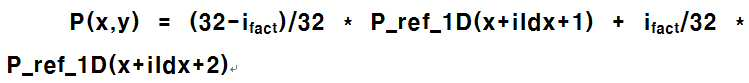
보간 필터의 계수는, 가중치 관련 파라미터 ifact에 기초하여 결정될 수 있다. 일 예로, 보간 필터의 계수는, 각도 선(angular line) 상에 위치한 소수 펠(fractional pel)과 정수 펠(즉, 각 참조 샘플들의 정수 위치) 사이의 거리에 기초하여 결정될 수 있다. The coefficients of the interpolation filter may be determined based on the weighting related parameter i fact . In one example, the coefficients of the interpolation filter may be determined based on the distance between the fractional pel located on the angular line and the integer pel (i.e., the integer position of each reference sample).
현재 블록의 인트라 예측 모드를 고려하였을 때, 예측 대상 샘플이 하나의 참조 샘플만으로 예측이 가능한 경우, 현재 블록의 인트라 예측 모드에 의해 특정되는 참조 샘플에 기초하여 예측 대상 샘플에 대한 예측 영상을 생성할 수 있다.When considering the intra prediction mode of the current block, if the prediction target sample can be predicted by only one reference sample, a prediction image for the prediction target sample is generated based on the reference sample specified by the intra prediction mode of the current block .
일 예로, 인트라 예측 모드의 각도 또는 인트라 예측 모드의 기울기에 따른 가상의 각도 선(angular line)이 일차원 레퍼런스 샘플 그룹 내 정수 펠(integer pel)(즉, 정수 위치의 참조 샘플)을 지나는 경우, 정수 펠 위치의 참조 샘플을 복사하거나, 정수 펠 위치의 참조 샘플과 예측 대상 샘플 사이의 위치를 고려하여, 예측 대상 샘플에 대한 예측 영상을 생성할 수 있다. 일 예로, 하기 수학식 10은 현재 블록의 인트라 예측 모드에 의해 특정되는 일차원 레퍼런스 샘플 그룹 내 참조 샘플 P_ref_1D(x+iIdx+1) 을 복사하여, 예측 대상 샘플에 대한 예측 영상 P(x, y)를 생성하는 예를 나타낸 것이다.For example, if an imaginary angular line along the slope of the intra-prediction mode or the angle of the intra-prediction mode passes through an integer pel in the one-dimensional reference sample group (i.e., the reference sample of the integer position) It is possible to copy a reference sample of the pel position or to generate a prediction image for the sample to be predicted considering the position between the reference sample at the integer pel position and the sample to be predicted. For example, the following equation (10) is obtained by copying the reference sample P_ref_1D (x + iIdx + 1) in the one-dimensional reference sample group specified by the intra-prediction mode of the current block, As shown in FIG.

4 tap 보간 필터(interpolation filter)를 사용하는 경우에는 다음 수학식 11과 같이 예측 영상을 생성할 수도 있다. When a 4 tap interpolation filter is used, a prediction image may be generated as shown in Equation (11).
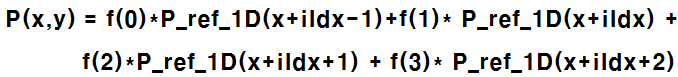
상기 수학식 11에서 P_ref_1D(x+idx-1)이 코딩 유닛의 경계 밖에 있는 샘플인 경우에는 P_ref_1D(x+idx)로 대체할 수 있다. 마찬가지 방법으로, 상기 수학식 11에서 P_ref_1D(x+idx+2)가 코딩 유닛 경계 밖에 있는 샘플인 경우에는P_ref_1D(x+idx+1)로 대체할 수 있다. 수학식 9 내지 11의 방법을 방향성 인트라 예측 샘플 보간 방법이라고 부른다. In Equation (11), P_ref_1D (x + idx-1) can be replaced with P_ref_1D (x + idx) when the sample is a sample located outside the boundary of the coding unit. Similarly, if P_ref_1D (x + idx + 2) in the above Equation (11) is a sample located outside the boundary of the coding unit, it can be replaced with P_ref_1D (x + idx + 1). The method of Equations (9) to (11) is referred to as a directional intra prediction sample interpolation method.
하지만, 전술한 다양한 형태의 코딩 유닛에 동일한 보간 필터를 적용하는 것은 오히려 부호화 및 복호화의 효율을 떨어뜨리는 원인이 될 수 있다. 에를 들어, CU 크기가 비정방형 이거나 또는 2x1, 16x2와 같은 극소 비대칭 코딩 유닛에서 4 tap 필터를 사용하여 예측 샘플을 생성하면 예측 영상이 오버 스무딩(over smoothing)되는 단점이 발생할 수도 있다. 따라서, 본 발명은 코딩 유닛의 종류에 따라 상이한 보간 필터를 적용하는 방법을 더 제안한다.However, applying the same interpolation filter to the various types of coding units described above may cause a reduction in the efficiency of encoding and decoding. For example, if a CU size is non-square or a 4 tap filter is used in a minimal asymmetric coding unit such as 2x1, 16x2, then a prediction sample may be generated, which may cause a disadvantage that the prediction image is over smoothed. Therefore, the present invention further proposes a method of applying a different interpolation filter depending on the type of coding unit.
도 29는 본 발명이 적용되는 실시예로서, 코딩 유닛의 종류에 따라 상이한 보간 필터를 적용하는 흐름도를 도시한 것이다. FIG. 29 shows a flow chart for applying different interpolation filters according to the types of coding units to which the present invention is applied.
도 29를 참조하면, 우선 인트라 예측 모드를 결정한다(S2900). 예를 들어, 인트라 예측 모드 결정은 전술한 도 20 및 도 21에 따른 방향성 인트라 예측 모드를 포함할 수 있다. Referring to FIG. 29, an intra prediction mode is determined first (S2900). For example, the intra prediction mode determination may include the directional intra prediction mode according to Figs. 20 and 21 described above.
이후, 코딩 유닛(CU)의 형태 및/또는 크기를 확인한다 (S2910). 예를 들어, 코딩 유닛의 형태는 전술한 도 3 내지 도 19에서 성세히 설명한 바와 같이, 정방형 또는 비정방형, 대칭형 또는 비대칭형, 극소 비대칭형 등으로 구분된다. 또한, 예를 들어, 코딩 유닛의 크기는, 전술한 도 3 도 19에서 성세히 설명한 바와 같이, 4x4, 8x8, 16x16, 32x32, 64x64, 128x128, 2x8, 2x16, 2x32, 4x8, 4x16, 4x32, 8x2, 8x4, 8x16, 8x32, 16x2, 16x4, 16x8, 16x32 등으로 다양한 크기가 존재한다. Then, the type and / or size of the coding unit (CU) is checked (S2910). For example, the form of the coding unit is divided into a square or a non-square, a symmetric or an asymmetric, and a very asymmetric, as described in detail in Figs. 3 to 19 described above. Also, for example, the size of the coding unit may be 4x4, 8x8, 16x16, 32x32, 64x64, 128x128, 2x8, 2x16, 2x32, 4x8, 4x16, 4x32, 8x2, 8x4, 8x16, 8x32, 16x2, 16x4, 16x8, 16x32, and the like.
다음, 상기 확인된 코딩 유닛의 형태 및/또느 크기에 따라, 방향성 인트라 예측 샘플 보간에 적용되는 보간 필터 종류를 결정한다(S2920). 예를 들어, 상기 보간 필터는 CU의 너비 또는 높이에 기초하여 서로 다른 탭 필터를 사용하여 방향성 인트라 예측 샘플 보간 방법을 사용할 수 있다. 다른 탭 필터라 함은 탭(tap) 수, 필터 계수, 필터 강도(strong/weak), 필터링 방향(vertical/horizontal) 중 적어도 하나가 상이함을 의미할 수 있다. 또한, 필터 강도에 따라 탭수, 필터 계수 등이 상이하게 결정될 수도 있다. 또한, 보간 필터링 방법으로 only vertical, only horizontal, both vertical and horizontal 중 어느 하나가 선택적으로 수행될 수 있다. 또한, 필터링 방향은 CU 내의 라인 단위(열/행) 또는 샘플 단위로 다르게 선택될 수 있다. 구체적으로, 예를 들어, 코딩 유닛의 너비 또는 높이 중 어느 하나의 값이 기준 값 N보다 작은 경우에는 4 tap 필터 대신에 2 tap 필터를 사용하여 방향성 인트라 예측 샘플 보간 방법을 수행하고 그 외의 CU에서는 4 tap 필터를 사용하여 방향성 인트라 예측 샘플 보간 방법을 수행할 수도 있다. Next, an interpolation filter type to be applied to the directional intra prediction sample interpolation is determined according to the type and / or size of the identified coding unit (S2920). For example, the interpolation filter may use a directional intra prediction sample interpolation method using different tap filters based on the width or height of the CU. Another tap filter may mean that at least one of tap number, filter coefficient, strong / weak and filtering direction (vertical / horizontal) is different. Further, the number of taps, the filter coefficient, and the like may be determined differently depending on the filter strength. Also, any one of only vertical, only horizontal, both vertical and horizontal can be selectively performed by the interpolation filtering method. In addition, the filtering direction can be selected differently in units of lines (column / row) or samples in the CU. Specifically, for example, if any one of the width or height of the coding unit is smaller than the reference value N, the directional intra prediction sample interpolation method is performed using a 2 tap filter instead of the 4 tap filter, and the
도 30 내지 도 32는 본 발명이 적용되는 실시예로서, 코딩 유닛의 종류에 따라 상이한 보간 필터를 적용하는 흐름도를 예시적으로 도시한 것이다. 30 to 32 illustrate a flow chart of applying different interpolation filters according to the types of coding units to which the present invention is applied.
관련하여, 도 30은 코딩 유닛이 정방형인지 비정방형인지에 따라 상이한 보간 필터를 적용한 예를 도시한 것이고, 도 31은 코딩 유닛이 비정방형인 경우 너비 또는 높이 크기에 따라 상이한 보간 필터를 적용한 예를 도시한 것이고, 도 32는 인터라 예측 모드에 따라 상이한 보간 필터를 적용한 예를 도시한 것이다.30 shows an example in which different interpolation filters are applied depending on whether the coding unit is square or non-square, and FIG. 31 shows an example in which a different interpolation filter is applied depending on the width or height size when the coding unit is non- And FIG. 32 shows an example in which different interpolation filters are applied according to the interlaced prediction mode.
도 30을 참조하면, 우선코딩 유닛이 비정방형 인지를 판단한다(S3000). 비정방형 CU 는, CU를 구성하는 너비와 높이가 서로 상이한 형태를 의미한다. Referring to FIG. 30, first, it is determined whether the coding unit is a non-square type (S3000). The non-square CU means a form in which the width and height constituting the CU are different from each other.
만약, 정방형 CU인 경우. n 탭 보간필터로 방향성 인트라 예측 샘플 보간을 적용한다(S3010). 반면, 비정방형인 경우, m 탭 보간필터로 방향성 인트라 예측 샘플 보간을 적용한다(S3020). 여기서, n과 m은 0보다 큰 상수이다. n은 m보다 크거나 동일한 값이다. 만약, n 탭과 m 탭이 동일한 탭수를 가진다면, n 탭 필터와 m 탭 필터는 상이한 필터 계수를 가지거나 또는 상이한 필터 강도(예, strong/weak)로 구분될 수 있다.If it is a square CU. The directional intra prediction sample interpolation is applied to the n tap interpolation filter (S3010). On the other hand, in the case of the non-square shape, directional intra prediction sample interpolation is applied to the m tap interpolation filter (S3020). Where n and m are constants greater than zero. n is greater than or equal to m. If the n-tap and the m-tap have the same number of taps, the n-tap filter and the m-tap filter may have different filter coefficients or be separated by different filter strengths (e.g., strong / weak).
구체적으로, 예를 들어, CU의 너비와 높이가 서로 다른 값을 가지는 비정방형일 때는 4 tap 필터 대신에 2 tap 필터를 사용하여 방향성 인트라 예측 샘플 보간 방법을 수행하고, 그 외의 CU에서는 4 tap 필터를 사용하여 방향성 인트라 예측 샘플 보간 방법을 수행할 수도 있다.For example, when the CU has a non-square shape having a different width and height, a directional intra prediction sample interpolation method is performed using a 2 tap filter instead of a 4 tap filter. In the other CUs, May be used to perform the directional intra prediction sample interpolation method.
도 31을 참조하면, 우선 코딩 유닛이 비정방형 인지를 판단한다(S3100). 만약 코딩 유닛이 비정방형 CU인 경우, 코딩 유닛의 너비 또는 높이중 적어도 어느 하나가 기준 크기보다 작은지를 판단한다(S3110). 예를 들어, 2x8 코딩 유닛인 경우, 너비 크기를 2로 결정할 수 있고, 8x2 코딩 유닛인 경우, 높이 크기를 2로 결정할 수 있다. 또한, 예를 들어 기준 크기는 4 로 설정할 수 있으나, 이에 한정되지는 않는다. Referring to FIG. 31, first, it is determined whether the coding unit is a non-square type (S3100). If the coding unit is a non-square CU, it is determined whether at least one of the width or the height of the coding unit is smaller than the reference size (S3110). For example, in the case of a 2x8 coding unit, the width size can be determined as 2. In the case of an 8x2 coding unit, the height size can be determined as 2. [ For example, the reference size can be set to 4, but is not limited thereto.
만약, 상기 단계 S3110 판단 결과, CU의 너비 또는 높이중 적어도 어느 하나가 기준 크기 (예, 4)보다 큰 경우에는, n 탭 보간필터로 방향성 인트라 예측 샘플 보간을 적용한다(S3120). 반면, CU의 너비 또는 높이중 적어도 어느 하나가 기준 크기 (예, 4)보다 작은 경우에는, m 탭 보간필터로 방향성 인트라 예측 샘플 보간을 적용한다(S3130). 여기서, n과 m은 0보다 큰 상수이다. n은 m보다 크거나 동일한 값이다. 만약, n 탭과 m 탭이 동일한 탭수를 가진다면, n 탭 필터와 m 탭 필터는 상이한 필터 계수를 가지거나 또는 상이한 필터 강도(예, strong/weak)로 구분될 수 있다. 또는 예를 들어, n=4 탭 필터, m=2탭 필터를 적용할 수 있다. If at least one of the width or height of the CU is larger than the reference size (e.g., 4) as a result of the determination in step S3110, directional intra prediction sample interpolation is applied to the n tap interpolation filter in step S3120. On the other hand, if at least one of the width or height of the CU is smaller than the reference size (e.g., 4), directional intra prediction sample interpolation is applied to the m tap interpolation filter (S3130). Where n and m are constants greater than zero. n is greater than or equal to m. If the n-tap and the m-tap have the same number of taps, the n-tap filter and the m-tap filter may have different filter coefficients or be separated by different filter strengths (e.g., strong / weak). Alternatively, for example, n = 4 tap filters and m = 2 tap filters can be applied.
또한, 만약 상기 단계 S3100 판단 결과, 코딩 유닛이 정방형 CU인 경우, 상기 n 탭 보간필터로 방향성 인트라 예측 샘플 보간을 적용한다(S3120). 또 다른 예로서, CU의 너비 또는 높이의 비(즉, w/h 또는 h/w)가 특정 임계값보다 작은 경우에는 4 tap 필터 대신에 2 tap 필터를 사용하여 방향성 인트라 예측 샘플 보간 방법을 수행하고, 그 외의 CU에서는 4 tap 필터를 사용하여 방향성 인트라 예측 샘플 보간 방법을 수행할 수도 있다. If it is determined in step S3100 that the coding unit is a square CU, directional intra prediction sample interpolation is applied to the n tap interpolation filter (S3120). As another example, when the ratio of the width or height of the CU (that is, w / h or h / w) is smaller than a certain threshold value, a directional intra prediction sample interpolation method is performed using a 2 tap filter in place of the 4 tap filter In other CUs, a directional intra prediction sample interpolation method may be performed using a 4 tap filter.
도 32을 참조하면, 현재 코딩 유닛의 인트라 예측 모드가 수평모드 인지 수직모드 인지를 판단한다(S3210). 수평 방향 인트라 예측 모드와 방향이 유사한 인트라 예측 모드를 수평 방향 인트라 예측 모드 (수평모드) 라고 부르고, 수직 방향 인트라 예측 모드와 방향이 유사한 인트라 예측 모드를 수직 방향 인트라 예측 모드 (수직 모드) 라고 부른다. Referring to FIG. 32, it is determined whether the intra prediction mode of the current coding unit is a horizontal mode or a vertical mode (S3210). An intra prediction mode whose direction is similar to that of the horizontal direction intra prediction mode is called a horizontal direction intra prediction mode (horizontal mode), and an intra prediction mode whose direction is similar to that of the vertical direction intra prediction mode is called a vertical direction intra prediction mode (vertical mode).
예를 들어, 도21과 같이 67개 인트라 예측 모드를 사용하는 경우에는 MODE 11 내지 MODE 18 사이의 인트라 예측 모드를 수평 모드로 간주할 수 있고,MODE 19 내지 MODE 27사이의 인트라 예측 모드를 수직 모드로 간주할 수 있다. 또 다른 예를 들어, 도 20과 같이 33개 인트라 예측 모드를 사용하는 경우에는 MODE 7 내지 MODE 13 사이의 인트라 예측 모드를 수평 모드로 간주할 수 있고,MODE 23내지 MODE 29사이의 인트라 예측 모드를 수직 모드로 간주할 수 있다. For example, when 67 intra prediction modes are used as shown in FIG. 21, the intra prediction mode between
만약, 코딩 유닛이 인트라 예측 수평모드에 해당되면, n 탭 보간필터로 방향성 인트라 예측 샘플 보간을 적용한다(S3220). 반면, 코딩 유닛이 인트라 예측 수직모드에 해당되면, m 탭 보간필터로 방향성 인트라 예측 샘플 보간을 적용한다(S3230). 여기서, n과 m은 0보다 큰 상수이다. n은 m보다 클 수도 있고, 작을 수도 있다. 혹은, n과 m은 동일할 수도 있으며, 이 경우 n tap 필터와 m tap 필터는 상이한 필터 계수를 가지거나 상이한 필터 강도를 가질 수 있다.If the coding unit is in the intra-prediction horizontal mode, directional intra prediction interpolation is applied to the n-tap interpolation filter (S3220). On the other hand, if the coding unit is in the intra-prediction vertical mode, directional intra prediction sample interpolation is applied to the m tap interpolation filter (S3230). Where n and m are constants greater than zero. n may be greater or less than m. Alternatively, n and m may be the same, in which case the n tap filter and the m tap filter may have different filter coefficients or different filter intensities.
관련하여, 또 다른 실시예로서, 상기 인트라 예측 모드가 수평모드인지 수직모드인지를 판단하는S3210 단계는, 코딩 유닛의 형태에 따라 적용여부를 결정하는 것이 가능하다. 즉, 예를 들어, 코딩 유닛이 비정방 코딩 유닛인 경우에만, 상기 S3210 단계를 적용할 수 있다. 또는, 코딩 유닛이 비대칭 코딩 유닛인 경우에만, 상기 S3210 단계를 적용할 수도 있다. 또는, 코딩 유닛이 극소 비대칭 코딩 유닛인 경우에만, 상기 S3210 단계를 적용할 수도 있다. 상기 극소 비대칭 코딩 유닛은, 비대칭 코딩 유닛의 일 종류로서, 코딩 유닛의 너비 또는 높이가 다른 한 쪽에 비해 매우 짧은 형태를 통칭하는 의미이다. 예를 들어, 2x16, 16x2, 4x32, 32x4 크기를 가지는 코딩 유닛 등이 이에 해당될 수 있다.In yet another embodiment, it is possible to determine whether the intra prediction mode is a horizontal mode or a vertical mode, in step S3210, depending on the type of the coding unit. That is, for example, the step S3210 can be applied only when the coding unit is a non-coding unit. Alternatively, the step S3210 may be applied only when the coding unit is an asymmetric coding unit. Alternatively, the step S3210 may be applied only when the coding unit is a minimal asymmetric coding unit. The micro-asymmetric coding unit is a type of asymmetric coding unit, meaning that the width or height of the coding unit is very short compared to the other side. For example, a coding unit having a size of 2x16, 16x2, 4x32, and 32x4 may be applicable.
구체적으로, 예를 들어, 2x16형태 비대칭 코딩 유닛에서, 인트라 예측 모드가 수평 방향 인트라 예측 모드 (수평모드)인 경우에는 n tap 필터를 사용할 수 있고, 수직 방향 인트라 예측 모드(수직모드)인 경우, m tap 필터를 사용할 수 있다.반면,또 다른 예로서, 16x2 형태 비대칭 코딩 유닛에서, 인트라 예측 모드가 수평 방향 인트라 예측 모드(수평모드)인 경우,m tap 필터를 사용할 수 있고, 수직 방향 인트라 예측 모드(수직모드)인 경우, n tap 필터를 사용할 수 있다.여기서, n과 m은 0보다 큰 상수이다. n은 m보다 클 수 있고, 혹은, n과 m은 동일할 수도 있으며, 이 경우 n tap 필터와 m tap 필터는 상이한 필터 계수를 가지거나 상이한 필터 강도를 가질 수 있다.Specifically, for example, in the 2x16 type asymmetric coding unit, if the intra prediction mode is the horizontal direction intra prediction mode (horizontal mode), the n tap filter can be used, and in the case of the vertical direction intra prediction mode (vertical mode) m tap filter can be used. On the other hand, in a 16x2 type asymmetric coding unit, if the intra prediction mode is a horizontal direction intra prediction mode (horizontal mode), an m tap filter can be used, Mode (vertical mode), an n tap filter can be used, where n and m are constants greater than zero. n may be greater than m, or n and m may be the same, in which case the n tap filter and the m tap filter may have different filter coefficients or different filter intensities.
도 33은 본 발명이 적용되는 또 다른 실시예로서, 인트라 예측 샘플 보간에 적용되는 네트워크 추상화 계층 (NAL)에 포함되는 신택스 요소(syntax element)를 예를 들어 도시한 것이다. 본 발명이 적용되는 NAL 유닛은, 예를 들어, 비디오 파라미터 셋 (VPS), 시퀀스 파라미터 셋(SPS), 픽쳐 파라미터 셋(PPS) 및 적어도 하나 이상의 슬라이스 셋(Slice)을 포함할 수 있다. FIG. 33 illustrates an example of a syntax element included in a network abstraction layer (NAL) applied to intra prediction sample interpolation according to another embodiment of the present invention. The NAL unit to which the present invention is applied may comprise, for example, a video parameter set (VPS), a sequence parameter set (SPS), a picture parameter set (PPS) and at least one slice set (Slice).
예를 들어, 도 33에서는 픽쳐 파라미터 셋(PPS)에 포함된 신택스 요소를 도시하였으나, 시퀀스 파라미터 셋(SPS) 또는 슬라이스 셋(Slice)에 해당 신택스 요소를 포함하는 것도 가능하다. 또한, 신택스 요소별로 시퀀스 단위 또는 픽쳐 단위에 공통적으로 적용될 신택스 요소는 시퀀스 파라미터 셋(SPS) 또는 픽쳐 파라미터 셋(PPS)에 포함되도록 할 수 있다. 반면, 해당 슬라이스에만 적용되는 신택스 요소는 슬라이스 셋(Slice)에 포함되는 것이 바람직하다. 따라서, 이는 부호화 성능 및 효율을 고려하여 선택이 가능하다.For example, although FIG. 33 shows a syntax element included in a picture parameter set (PPS), it is also possible to include a syntax element in a sequence parameter set (SPS) or a slice set (Slice). In addition, a syntax element to be commonly applied to a sequence unit or a picture unit for each syntax element may be included in a sequence parameter set (SPS) or a picture parameter set (PPS). On the other hand, a syntax element that is applied only to the slice is preferably included in the slice set. Therefore, it can be selected in consideration of coding performance and efficiency.
신택스 요소 'PreSample_filter_flag'는 인트라 예측 샘플에 보간 필터가 작용되는 지를 나타내는 정보이다. 예를 들어, PreSample_filter_flag 값이 '1'이면 현재 코딩 블록에 인트라 예측 샘플 보간이 적용됨을 의미하고, PreSample_filter_flag 값이 '0'이면 현재 코딩 블록에 인트라 예측 샘플 보간이 적용되지 않음을 의미한다.The syntax element 'PreSample_filter_flag' is information indicating whether the interpolation filter is applied to the intra prediction sample. For example, if the value of PreSample_filter_flag is '1', intra-prediction sample interpolation is applied to the current coding block. If the value of PreSample_filter_flag is '0', intra-prediction interpolation is not applied to the current coding block.
또한, 신택스 요소 'idx_PreSample_filte'는 인트라 예측 샘플에 적용된 보간 필터의 종류를 인텍싱하여 표시하는 정보이다. 예를 들어, 전술한 4탭 필터, 2탭 필터, 필터 계수, 필터 강도 들의 조합으로 보간 필터 타입을 결정하고, 이를 인텍싱하는 정보로 활용될 수 있다. The syntax element 'idx_PreSample_filte' is information for indexing and displaying the kind of the interpolation filter applied to the intra prediction sample. For example, the combination of the 4-tap filter, the 2-tap filter, the filter coefficient, and the filter strength described above can be used as information for determining the interpolation filter type and indexing the same.
상술한 실시예는 일련의 단계 또는 순서도를 기초로 설명되고 있으나, 이는 발명의 시계열적 순서를 한정한 것은 아니며, 필요에 따라 동시에 수행되거나 다른 순서로 수행될 수 있다. 또한, 상술한 실시예에서 블록도를 구성하는 구성요소(예를 들어, 유닛, 모듈 등) 각각은 하드웨어 장치 또는 소프트웨어로 구현될 수도 있고, 복수의 구성요소가 결합하여 하나의 하드웨어 장치 또는 소프트웨어로 구현될 수도 있다. 상술한 실시예는 다양한 컴퓨터 구성요소를 통하여 수행될 수 있는 프로그램 명령어의 형태로 구현되어 컴퓨터 판독 가능한 기록 매체에 기록될 수 있다. 상기 컴퓨터 판독 가능한 기록 매체는 프로그램 명령어, 데이터 파일, 데이터 구조 등을 단독으로 또는 조합하여 포함할 수 있다. 컴퓨터 판독 가능한 기록 매체의 예에는, 하드 디스크, 플로피 디스크 및 자기 테이프와 같은 자기 매체, CD-ROM, DVD와 같은 광기록 매체, 플롭티컬 디스크(floptical disk)와 같은 자기-광 매체(magneto-optical media), 및 ROM, RAM, 플래시 메모리 등과 같은 프로그램 명령어를 저장하고 수행하도록 특별히 구성된 하드웨어 장치가 포함된다. 상기 하드웨어 장치는 본 발명에 따른 처리를 수행하기 위해 하나 이상의 소프트웨어 모듈로서 작동하도록 구성될 수 있다.Although the above-described embodiments have been described on the basis of a series of steps or flowcharts, they do not limit the time-series order of the invention, and may be performed simultaneously or in different orders as necessary. Further, in the above-described embodiments, each of the components (for example, units, modules, etc.) constituting the block diagram may be implemented by a hardware device or software, and a plurality of components may be combined into one hardware device or software . The above-described embodiments may be implemented in the form of program instructions that may be executed through various computer components and recorded in a computer-readable recording medium. The computer-readable recording medium may include program commands, data files, data structures, and the like, alone or in combination. Examples of computer-readable recording media include magnetic media such as hard disks, floppy disks and magnetic tape, optical recording media such as CD-ROMs and DVDs, magneto-optical media such as floptical disks, media, and hardware devices specifically configured to store and execute program instructions such as ROM, RAM, flash memory, and the like. The hardware device may be configured to operate as one or more software modules for performing the processing according to the present invention.
100 : 부호화기 110 : 픽쳐분할부
120, 230 : 인터 예측부 125, 235 : 인트라 예측부
130 : 변환부
135 : 양자화부
200 : 복호화기 210 : 엔트로피 복호화부
215 : 재정렬부 220 : 역양자화부
225 : 역변환부 100: encoder 110: picture division unit
120, 230:
130: conversion unit 135: quantization unit
200: Decoder 210: Entropy decoding unit
215: rearrangement unit 220: dequantization unit
225: Inverse transform unit
Claims (15)
현재 코딩 블록의 형태에 따라, 상기 방향성 인트라 예측 모드에 적용되는 방향성 인트라 예측 샘플 보간을 위한 보간 필터 종류를 결정하는 단계, 및
상기 결정된 보간 필터를 적용하여 인트라 예측 샘플을 생성하는 단계를 포함하는, 영상 복호화 방법.
Confirming a directional intra prediction mode of the current coding block,
Determining an interpolation filter type for directional intra prediction sample interpolation applied to the directional intra prediction mode according to the type of the current coding block,
And applying the determined interpolation filter to generate an intra prediction sample.
상기 현재 코딩 블록의 형태가 비정방형인지 정방형인지에 따라, 서로 다른 필터 탭을 가지는 보간 필터를 적용하는, 영상 복호화 방법.
The method according to claim 1,
Wherein an interpolation filter having different filter taps is applied according to whether the current coding block type is a non-square or a square.
상기 현재 코딩 블록의 형태가 비정방형인 경우는,, 정방형인 경우보다 작은 필터 탭을 가지는 보간 필터를 적용하는, 영상 복호화 방법.
3. The method of claim 2,
And applying an interpolation filter having a smaller filter tap when the current coding block is of a non-square shape.
상기 현재 코딩 블록의 너비 또는 높이에 따라, 서로 다른 필터 탭을 가지는 보간 필터를 적용하는, 영상 복호화 방법.
The method according to claim 1,
Wherein an interpolation filter having different filter taps is applied according to the width or height of the current coding block.
상기 현재 코딩 블록의 형태가 비정방형이고, 너비 또는 높이중 적어도 어느 하나가 기준크기 보다 작은 경우에는, 기준 크기 보다 큰 경우보다 작은 필터 탭을 가지는 보간 필터를 적용하는, 영상 복호화 방법.
5. The method of claim 4,
Wherein the interpolation filter having a filter tap smaller than that of the current coding block is applied when the shape of the current coding block is non-square and at least one of the width and the height is smaller than the reference size.
상기 현재 코딩 블록의 너비 대 높이비(w/h)가 임계값대비 작은 경우는, 임계값대비 큰 경우 보다 작은 필터 탭을 가지는보간 필터를 적용하는, 영상 복호화 방법.
5. The method of claim 4,
Wherein an interpolation filter having a smaller filter tap than a threshold value is applied when the width-to-height ratio (w / h) of the current coding block is smaller than a threshold value.
상기 현재 코딩 블록의 방향성 인트라 예측 모드에 따라, 서로 다른 필터 탭을 가지는 보간 필터를 적용하는, 영상 복호화 방법.
The method according to claim 1,
Wherein an interpolation filter having different filter taps is applied according to a directional intra prediction mode of the current coding block.
상기 인트라 예측 모드가 수평모드인지 수직모드인지에 따라서로 다른 필터 탭을 가지는보간 필터를 적용하는, 영상 복호화 방법.
8. The method of claim 7,
Wherein an interpolation filter having different filter taps is applied depending on whether the intra prediction mode is a horizontal mode or a vertical mode.
상기 현재 코딩 블록의 너비 또는 높이중 적어도 어느 하나가, 기준값보다 작으면, 작은 필터 탭을 가지는 보간 필터를 적용하는, 영상 복호화 방법.
5. The method of claim 4,
Wherein an interpolation filter having a small filter tap is applied if at least one of a width or a height of the current coding block is smaller than a reference value.
상기 보간 필터 종류가 결정되면, 수직 방향, 수평 방향, 또는 수직/수평 방향 중 어느 하나가 선택적으로 수행되는 보간 필터링 단계를 더 포함하는, 영상 복호화 방법.
The method according to claim 1,
Further comprising an interpolation filtering step in which one of a vertical direction, a horizontal direction, and a vertical / horizontal direction is selectively performed when the interpolation filter type is determined.
상기 현재 코딩 블록의 형태에 따라, 보간 필터의 탭수는 동일하되, 상이한 필터계수를 가지는 보간 필터를 달리 적용하는, 영상 복호화 방법.
The method according to claim 1,
Wherein an interpolation filter having the same number of taps of an interpolation filter but having different filter coefficients is applied differently according to the type of the current coding block.
상기 현재 코딩 블록의 형태에 따라, 보간 필터의 탭수는 동일하되, 상이한 필터 강도를 가지는 보간 필터를 달리 적용하는, 영상 복호화 방법.
The method according to claim 1,
Wherein an interpolation filter having the same number of taps of the interpolation filter but different filter strength is applied differently according to the type of the current coding block.
현재 코딩 블록의 형태에 따라, 상기 방향성 인트라 예측 모드에 적용되는 방향성 인트라 예측 샘플 보간을 위한 보간 필터 종류를 결정하는 단계, 및
상기 결정된 보간 필터를 적용하여 인트라 예측 샘플을 생성하는 단계를 포함하는, 영상 부호화 방법.
Confirming a directional intra prediction mode of the current coding block,
Determining an interpolation filter type for directional intra prediction sample interpolation applied to the directional intra prediction mode according to the type of the current coding block,
And generating an intra prediction sample by applying the determined interpolation filter.
Determining a directional intra prediction mode of the current coding block and determining an interpolation filter type for directional intra prediction sample interpolation applied to the directional intra prediction mode according to the current coding block type, And a decoder for generating a prediction sample.
A recording medium including a video signal bitstream, the video signal bitstream included in the recording medium comprising: checking a directional intra prediction mode of a current coding block; decoding the directional intra prediction mode Determining a type of an interpolation filter for interpolation of directional intra prediction samples to be applied to the intra prediction sample, and generating the intra prediction samples by applying the determined interpolation filter.
Applications Claiming Priority (2)
| Application Number | Priority Date | Filing Date | Title |
|---|---|---|---|
| KR20170024642 | 2017-02-24 | ||
| KR1020170024642 | 2017-02-24 |
Publications (2)
| Publication Number | Publication Date |
|---|---|
| KR20180098160A true KR20180098160A (en) | 2018-09-03 |
| KR102511546B1 KR102511546B1 (en) | 2023-03-17 |
Family
ID=63253922
Family Applications (1)
| Application Number | Title | Priority Date | Filing Date |
|---|---|---|---|
| KR1020180021638A Active KR102511546B1 (en) | 2017-02-24 | 2018-02-23 | Method and apparatus for processing a video signal |
Country Status (2)
| Country | Link |
|---|---|
| KR (1) | KR102511546B1 (en) |
| WO (1) | WO2018155985A1 (en) |
Cited By (2)
| Publication number | Priority date | Publication date | Assignee | Title |
|---|---|---|---|---|
| WO2020055208A1 (en) * | 2018-09-14 | 2020-03-19 | 엘지전자 주식회사 | Image prediction method and apparatus for performing intra prediction |
| WO2023234681A1 (en) * | 2022-05-30 | 2023-12-07 | 주식회사 케이티 | Image encoding/decoding method and apparatus |
Families Citing this family (9)
| Publication number | Priority date | Publication date | Assignee | Title |
|---|---|---|---|---|
| PL3849184T3 (en) | 2018-11-08 | 2023-07-24 | Guangdong Oppo Mobile Telecommunications Corp., Ltd. | METHOD OF CODING/DECODING THE IMAGE SIGNAL AND DEVICE FOR IMPROVING IT |
| EP3766249A4 (en) * | 2019-01-08 | 2022-01-26 | Tencent America Llc | METHOD AND DEVICE FOR MEMORY BANDWIDTH REDUCTION FOR SMALL INTERMEDIATE BLOCKS |
| CN113366855B (en) * | 2019-02-03 | 2025-06-24 | 北京字节跳动网络技术有限公司 | Asymmetric quadtree partitioning based on conditions |
| JP7145793B2 (en) * | 2019-03-11 | 2022-10-03 | Kddi株式会社 | Image decoding device, image decoding method and program |
| AU2020250609B2 (en) * | 2019-04-01 | 2023-09-07 | Beijing Bytedance Network Technology Co., Ltd. | Using interpolation filters for history based motion vector prediction |
| WO2020221374A1 (en) * | 2019-05-02 | 2020-11-05 | Beijing Bytedance Network Technology Co., Ltd. | Intra video coding using multiple reference filters |
| JP7359942B2 (en) | 2019-08-20 | 2023-10-11 | 北京字節跳動網絡技術有限公司 | Selective use of alternative interpolation filters in video processing |
| CN114600452A (en) * | 2019-09-18 | 2022-06-07 | Vid拓展公司 | Adaptive Interpolation Filter for Motion Compensation |
| EP4074045B1 (en) * | 2019-12-10 | 2026-04-15 | Guangdong Oppo Mobile Telecommunications Corp., Ltd. | Methods for encoding and decoding pictures and associated apparatus and systems |
Citations (2)
| Publication number | Priority date | Publication date | Assignee | Title |
|---|---|---|---|---|
| US20120230413A1 (en) * | 2011-03-11 | 2012-09-13 | General Instrument Corporation | Interpolation filter selection using prediction unit (pu) size |
| WO2012134046A2 (en) * | 2011-04-01 | 2012-10-04 | 주식회사 아이벡스피티홀딩스 | Method for encoding video |
Family Cites Families (2)
| Publication number | Priority date | Publication date | Assignee | Title |
|---|---|---|---|---|
| KR101353304B1 (en) * | 2008-10-24 | 2014-01-21 | 에스케이 텔레콤주식회사 | Video Encoding/Decoding Method and Apparatus Using Adaptive Interpolation Filter Coefficient |
| CN104980738B (en) * | 2010-09-30 | 2017-04-12 | 三星电子株式会社 | Method And Device For Interpolating Images By Using A Smoothing Interpolation Filter |
-
2018
- 2018-02-23 KR KR1020180021638A patent/KR102511546B1/en active Active
- 2018-02-26 WO PCT/KR2018/002342 patent/WO2018155985A1/en not_active Ceased
Patent Citations (2)
| Publication number | Priority date | Publication date | Assignee | Title |
|---|---|---|---|---|
| US20120230413A1 (en) * | 2011-03-11 | 2012-09-13 | General Instrument Corporation | Interpolation filter selection using prediction unit (pu) size |
| WO2012134046A2 (en) * | 2011-04-01 | 2012-10-04 | 주식회사 아이벡스피티홀딩스 | Method for encoding video |
Cited By (4)
| Publication number | Priority date | Publication date | Assignee | Title |
|---|---|---|---|---|
| WO2020055208A1 (en) * | 2018-09-14 | 2020-03-19 | 엘지전자 주식회사 | Image prediction method and apparatus for performing intra prediction |
| US11445216B2 (en) | 2018-09-14 | 2022-09-13 | Lg Electronics Inc. | Image prediction method and apparatus for performing intra prediction |
| US11843801B2 (en) | 2018-09-14 | 2023-12-12 | Lg Electronics Inc. | Image prediction method and apparatus for performing intra prediction |
| WO2023234681A1 (en) * | 2022-05-30 | 2023-12-07 | 주식회사 케이티 | Image encoding/decoding method and apparatus |
Also Published As
| Publication number | Publication date |
|---|---|
| KR102511546B1 (en) | 2023-03-17 |
| WO2018155985A1 (en) | 2018-08-30 |
Similar Documents
| Publication | Publication Date | Title |
|---|---|---|
| KR102599115B1 (en) | Method and apparatus for processing a video signal | |
| KR102416257B1 (en) | Method and apparatus for processing a video signal | |
| KR102664475B1 (en) | Method and apparatus for processing a video signal | |
| KR102583092B1 (en) | Method and apparatus for processing a video signal | |
| KR102511546B1 (en) | Method and apparatus for processing a video signal | |
| KR102435000B1 (en) | Method and apparatus for processing a video signal | |
| KR102601267B1 (en) | Method and apparatus for processing a video signal | |
| CN110024410B (en) | Methods for encoding and decoding video | |
| KR102424420B1 (en) | Method and apparatus for processing a video signal | |
| KR20180065953A (en) | Method and apparatus for processing a video signal | |
| KR20180098161A (en) | Method and apparatus for processing a video signal | |
| KR102813167B1 (en) | Video signal processing method and apparatus | |
| KR20180001479A (en) | Method and apparatus for processing a video signal | |
| CN110710216B (en) | Video signal processing method and device | |
| KR20190028325A (en) | Method and apparatus for processing a video signal | |
| CN112219397A (en) | Method for encoding/decoding video signal and apparatus therefor | |
| KR20180001478A (en) | Method and apparatus for processing a video signal | |
| KR20180031616A (en) | Method and apparatus for processing a video signal | |
| KR20180025284A (en) | Method and apparatus for processing a video signal | |
| KR102601268B1 (en) | Method and apparatus for processing a video signal | |
| KR20180037599A (en) | Method and apparatus for processing a video signal | |
| CN116600142B (en) | Methods for decoding or encoding images and methods for transmitting image data | |
| KR102825691B1 (en) | Method and apparatus for processing a video signal | |
| KR20180056396A (en) | Method and apparatus for processing a video signal | |
| KR20210030889A (en) | Method for encoding/decoding a video signal and device therefor |
Legal Events
| Date | Code | Title | Description |
|---|---|---|---|
| PA0109 | Patent application |
Patent event code: PA01091R01D Comment text: Patent Application Patent event date: 20180223 |
|
| PG1501 | Laying open of application | ||
| A201 | Request for examination | ||
| PA0201 | Request for examination |
Patent event code: PA02012R01D Patent event date: 20210223 Comment text: Request for Examination of Application Patent event code: PA02011R01I Patent event date: 20180223 Comment text: Patent Application |
|
| E902 | Notification of reason for refusal | ||
| PE0902 | Notice of grounds for rejection |
Comment text: Notification of reason for refusal Patent event date: 20220127 Patent event code: PE09021S01D |
|
| E90F | Notification of reason for final refusal | ||
| PE0902 | Notice of grounds for rejection |
Comment text: Final Notice of Reason for Refusal Patent event date: 20220816 Patent event code: PE09021S02D |
|
| E701 | Decision to grant or registration of patent right | ||
| PE0701 | Decision of registration |
Patent event code: PE07011S01D Comment text: Decision to Grant Registration Patent event date: 20230209 |
|
| GRNT | Written decision to grant | ||
| PR0701 | Registration of establishment |
Comment text: Registration of Establishment Patent event date: 20230314 Patent event code: PR07011E01D |
|
| PR1002 | Payment of registration fee |
Payment date: 20230314 End annual number: 3 Start annual number: 1 |
|
| PG1601 | Publication of registration |