KR20180098141A - Hole plug - Google Patents
Hole plug Download PDFInfo
- Publication number
- KR20180098141A KR20180098141A KR1020180018537A KR20180018537A KR20180098141A KR 20180098141 A KR20180098141 A KR 20180098141A KR 1020180018537 A KR1020180018537 A KR 1020180018537A KR 20180018537 A KR20180018537 A KR 20180018537A KR 20180098141 A KR20180098141 A KR 20180098141A
- Authority
- KR
- South Korea
- Prior art keywords
- flange portion
- lid
- opening
- panel
- flange
- Prior art date
- Legal status (The legal status is an assumption and is not a legal conclusion. Google has not performed a legal analysis and makes no representation as to the accuracy of the status listed.)
- Ceased
Links
- 230000002093 peripheral effect Effects 0.000 claims abstract description 40
- 230000000903 blocking effect Effects 0.000 claims abstract 2
- 230000005540 biological transmission Effects 0.000 abstract description 8
- 230000000694 effects Effects 0.000 description 21
- 238000009413 insulation Methods 0.000 description 18
- 238000007789 sealing Methods 0.000 description 9
- 150000001336 alkenes Chemical class 0.000 description 7
- JRZJOMJEPLMPRA-UHFFFAOYSA-N olefin Natural products CCCCCCCC=C JRZJOMJEPLMPRA-UHFFFAOYSA-N 0.000 description 7
- 239000000463 material Substances 0.000 description 5
- 229920005989 resin Polymers 0.000 description 4
- 239000011347 resin Substances 0.000 description 4
- 229920003002 synthetic resin Polymers 0.000 description 4
- 239000000057 synthetic resin Substances 0.000 description 4
- 229920001169 thermoplastic Polymers 0.000 description 4
- 239000004416 thermosoftening plastic Substances 0.000 description 4
- 239000006260 foam Substances 0.000 description 3
- 230000037431 insertion Effects 0.000 description 3
- 238000003780 insertion Methods 0.000 description 3
- 238000005187 foaming Methods 0.000 description 2
- 230000008719 thickening Effects 0.000 description 2
- 238000005516 engineering process Methods 0.000 description 1
- 230000001747 exhibiting effect Effects 0.000 description 1
- 238000004519 manufacturing process Methods 0.000 description 1
- 230000000149 penetrating effect Effects 0.000 description 1
- 230000000717 retained effect Effects 0.000 description 1
Images


Classifications
-
- B—PERFORMING OPERATIONS; TRANSPORTING
- B60—VEHICLES IN GENERAL
- B60R—VEHICLES, VEHICLE FITTINGS, OR VEHICLE PARTS, NOT OTHERWISE PROVIDED FOR
- B60R13/00—Elements for body-finishing, identifying, or decorating; Arrangements or adaptations for advertising purposes
- B60R13/08—Insulating elements, e.g. for sound insulation
-
- B—PERFORMING OPERATIONS; TRANSPORTING
- B60—VEHICLES IN GENERAL
- B60Y—INDEXING SCHEME RELATING TO ASPECTS CROSS-CUTTING VEHICLE TECHNOLOGY
- B60Y2306/00—Other features of vehicle sub-units
- B60Y2306/09—Reducing noise
Landscapes
- Physics & Mathematics (AREA)
- Acoustics & Sound (AREA)
- Engineering & Computer Science (AREA)
- Mechanical Engineering (AREA)
- Vehicle Interior And Exterior Ornaments, Soundproofing, And Insulation (AREA)
- Body Structure For Vehicles (AREA)
- Soundproofing, Sound Blocking, And Sound Damping (AREA)
- Pressure Vessels And Lids Thereof (AREA)
Abstract
(과제) 차체 등의 패널의 개구를 폐색하는 홀 플러그에 관해서, 내부에 공간을 형성함으로써 이 공간 내의 공기층에 의해서 소리 및 진동의 전달을 저감 내지는 차단하고, 차음성을 향상시키는 것을 과제로 한다.
(해결 수단) 홀 플러그(200)는, 패널(210)에 형성된 개구(211)의 일방측 둘레가장자리(예를 들면 상측 둘레가장자리)에 맞닿는 환형상의 제 1 플랜지부(220)와, 제 1 플랜지부(220)와 함께 개구(211)를 폐색하는 제 1 덮개부(230)와, 개구(211)의 타방측 둘레가장자리(예를 들면 하측 둘레가장자리)에 걸어맞춤으로써, 제 1 플랜지부(220) 또는 제 1 덮개부(230)와의 사이에서 소정의 공간(250)을 구비하여 개구(211)를 폐색하는 폐색부(240)를 구비한다.[PROBLEMS] To provide a hole for blocking an opening of a panel of a vehicle body or the like, a space is formed in the interior of the space so as to reduce or prevent the transmission of sound and vibration by the air layer in the space.
The hole plug 200 includes an annular first flange portion 220 abutting one peripheral edge (for example, an upper peripheral edge) of an opening 211 formed in the panel 210, A first lid 230 that closes the opening 211 together with the supporting portion 220 and a second lid 230 that engages with the other peripheral edge (e.g., the lower peripheral edge) of the opening 211 to form the first flange 220 And a closure part 240 provided with a predetermined space 250 between the first cover part 230 and the first cover part 230 to close the opening 211.
Description
이 발명은 차체 등의 패널의 개구를 폐색하는 홀 플러그에 관하여, 내부에 공간을 형성함으로써 이 공간 내의 공기층에 의해서 소리 및 진동의 전달을 저감 내지는 차단하고, 차음성(遮音性)을 향상시킬 수 있도록 한 것이다.
The present invention relates to a hole plug for closing an opening of a panel of a vehicle body or the like by forming a space therein so as to reduce or prevent the transmission of sound and vibration by the air layer in this space and to improve the sound- .
종래에, 판재의 구멍에 장착되는 지수용의 홀 플러그로서, 이 홀 플러그에는 제 1 플랜지와 제 2 플랜지를 구비하고, 판재를 양면에서 밀봉 가능한 것이 알려져 있다(특허문헌 1의 단락 번호 [0025] 및 [0029]~[0033], 도 4 및 도 10 참조). 또, 종래에, 차체 패널의 단차형상의 구멍부에 장착되는 부방음재로서, 이 부방음재에는 고밀도부와 저밀도부를 구비한 차량용 방음 구조가 알려져 있다(특허문헌 2의 단락 번호 [0018] 및 [0021], 도 2 참조).
[0003] Conventionally, it has been known that as a hole plug for an index to be mounted on a hole of a plate material, the hole plug is provided with a first flange and a second flange and is capable of sealing the plate material on both sides (see paragraph [ And [0029] to [0033], Figs. 4 and 10). [0003] Conventionally, as a soundproofing material to be mounted on a stepped hole of a vehicle body panel, a soundproofing structure for a vehicle having a high density portion and a low density portion is known as the soundproofing material (see paragraphs [0018] and [0021] ], See Fig. 2).
그러나, 상기한 특허문헌 1에 기재된 종래의 홀 플러그는 밀봉성을 과제로 하며, 차음성에 대해서는 다루고 있지 있다.However, the conventional hole plug described in the above-mentioned Patent Document 1 has a problem of sealing property and does not deal with a car audio.
또, 상기한 특허문헌 2에 기재된 종래의 차량용 방음 구조의 부방음재에서는, 방음성을 과제로 하고 있지만, 애초에 구멍을 폐색하는 구조를 가지고 있지 않다.In the above-described conventional soundproofing material for a vehicle soundproofing structure described in Patent Document 2, although the soundproofing is a problem, it does not have a structure to close the hole at first.
그래서, 각 청구항에 각각 기재된 각 발명은 상기한 종래의 기술이 가지는 문제점을 감안하여 이루어진 것으로서, 그 목적으로 하는 부분은 다음의 점에 있다.Therefore, each invention described in each claim is made in view of the problems of the above-described conventional technology, and the object thereof is as follows.
(청구항 1)(Claim 1)
청구항 1에 기재된 발명은, 다음의 점을 목적으로 한다.The invention described in claim 1 aims at the following points.
즉, 청구항 1에 기재된 발명은, 내부에 공간을 형성함으로써 이 공간 내의 공기층에 의해서 소리 및 진동의 전달을 저감 내지는 차단하고, 차음성을 향상시킬 수 있도록 한 것이다.In other words, the invention described in claim 1 is configured so as to reduce the transmission of sound and vibration by the air layer in the space by forming a space therein, thereby improving the sound of the vehicle.
(청구항 2)(Claim 2)
청구항 2에 기재된 발명은, 상기한 청구항 1에 기재된 발명의 목적에 더하여 다음의 점을 목적으로 한다.The invention described in claim 2 is aimed at the following points in addition to the object of the invention described in claim 1 above.
즉, 청구항 2에 기재된 발명은, 공간이 제 1 덮개부와 제 2 덮개부의 사이에 위치하기 때문에 밀폐된 공기층이 형성되고, 이 밀폐된 공기층에 의해서 차음성을 향상시킬 수 있을 뿐만 아니라, 환형상의 제 2 플랜지부에 의해서 차음성을 더 향상시킬 수 있도록 한 것이다.In other words, the invention described in claim 2 is characterized in that a sealed air layer is formed because the space is located between the first lid part and the second lid part, and the sound insulation can be improved by the sealed air layer, And the second flange portion can further improve the sound insulation.
(청구항 3)(Claim 3)
청구항 3에 기재된 발명은, 상기한 청구항 2에 기재된 발명의 목적에 더하여 다음의 점을 목적으로 한다.The invention described in claim 3 is aimed at the following points in addition to the object of the invention described in claim 2 above.
즉, 청구항 3에 기재된 발명은, 제 1 부재와 제 2 부재로 분리함으로써, 양 부재의 사이에 있어서의 소리 및 진동의 전달을 저감 내지는 차단하고, 차음성을 향상시킬 수 있을 뿐만 아니라, 제조를 간편하게 할 수 있고, 또한 양 부재를 걸어맞춤 상태로 할 수 있기 때문에 납품시 등의 취급을 용이하게 할 수 있도록 한 것이다.In other words, the invention described in claim 3 separates the first member and the second member so as to reduce or prevent the transmission of sound and vibration between the both members, thereby improving the sound insulation, And both members can be brought into the engagement state, so that handling such as delivery can be facilitated.
(청구항 4)(Claim 4)
청구항 4에 기재된 발명은, 상기한 청구항 3에 기재된 발명의 목적에 더하여 다음의 점을 목적으로 한다.The invention described in claim 4 is aimed at the following points in addition to the object of the invention described in claim 3 above.
즉, 청구항 4에 기재된 발명은, 패널을 협지(挾持)시킴으로써 플랜지부의 패널에 대한 밀착성을 향상시키고, 차음성을 더 향상시킬 수 있도록 한 것이다.In other words, the invention described in claim 4 is intended to enhance the adhesion of the flange portion to the panel by sandwiching the panel, and to further improve the car sound.
(청구항 5)(Claim 5)
청구항 5에 기재된 발명은, 상기한 청구항 3에 기재된 발명의 목적에 더하여 다음의 점을 목적으로 한다.According to a fifth aspect of the present invention, In addition to its purpose, it aims at the following points.
즉, 청구항 5에 기재된 발명은, 제 1 플랜지부와 제 2 플랜지부 중 어느 일방과 협동하여 패널을 협지하는 환형상 플랜지부를 형성함으로써, 차음성을 더 향상시킬 수 있도록 한 것이다.In other words, the invention described in claim 5 is configured to further improve the sound insulation by forming an annular flange portion that cooperates with either one of the first flange portion and the second flange portion to sandwich the panel.
(청구항 6)(Claim 6)
청구항 6에 기재된 발명은, 상기한 청구항 4에 기재된 발명의 목적에 더하여 다음의 점을 목적으로 한다.According to a sixth aspect of the present invention, In addition to its purpose, it aims at the following points.
즉, 청구항 6에 기재된 발명은, 제 1 플랜지부와 제 2 플랜지부 중 어느 일방과 협동하여 패널을 협지하는 환형상 플랜지부를 형성함으로써, 차음성을 더 향상시킬 수 있도록 한 것이다.In other words, the invention according to claim 6 is configured to further improve the sound difference by forming the annular flange portion that cooperates with either one of the first flange portion and the second flange portion and sandwiching the panel.
(청구항 7)(Claim 7)
청구항 7에 기재된 발명은, 상기한 청구항 3 내지 청구항 6 중 어느 한 항에 기재된 발명의 목적에 더하여 다음의 점을 목적으로 한다.The invention described in claim 7 is aimed at the following points in addition to the object of the invention described in any one of claims 3 to 6. [
즉, 청구항 7에 기재된 발명은, 제 1 플랜지부와 제 2 플랜지부 중 어느 일방을 타방의 플랜지부보다 작은 직경으로 함으로써, 패널에 대한 장착성을 향상시킬 수 있도록 한 것이다.In other words, the invention recited in claim 7 makes it possible to improve the attachability to the panel by making either one of the first flange portion and the second flange portion smaller in diameter than the other flange portion.
(청구항 8)(Claim 8)
청구항 8에 기재된 발명은, 상기한 청구항 3 내지 청구항 6 중 어느 한 항에 기재된 발명의 목적에 더하여 다음의 점을 목적으로 한다.The invention described in claim 8 is aimed at the following points in addition to the object of the invention described in any one of claims 3 to 6.
즉, 청구항 8에 기재된 발명은, 걸림고정부를 타방의 다리부에 의해서 둘러싸인 내부에 위치하는 공간을 통과하는 구성으로 함으로써, 직경방향의 스페이스를 감소할 수 있고, 양 부재를 이탈하기 어렵게 걸어맞출 수 있도록 한 것이다.In other words, the invention described in claim 8 is characterized in that the space in the radial direction can be reduced by making the latching section pass through a space located inside, surrounded by the other leg section, .
(청구항 9)(Claim 9)
청구항 9에 기재된 발명은, 상기한 청구항 2 내지 청구항 6 중 어느 한 항에 기재된 발명의 목적에 더하여 다음의 점을 목적으로 한다.The invention described in claim 9 is aimed at the following points in addition to the object of the invention described in any one of claims 2 to 6 above.
즉, 청구항 9에 기재된 발명은, 제 1 덮개부와 제 2 덮개부 중 적어도 어느 일방을 발포성(發泡性)을 가지는 구성으로 함으로써, 차음성을 더 향상시킬 수 있도록 한 것이다.
In other words, the invention according to claim 9 is characterized in that at least one of the first lid part and the second lid part has a foaming property so that the car sound can be further improved.
각 청구항에 각각 기재된 각 발명은 상기한 각 목적을 달성하기 위해서 이루어진 것으로서, 각 발명의 특징점을 도면에 나타낸 발명의 실시형태를 이용하여 이하에 설명한다.Each of the inventions described in each claim is made in order to attain the above objects, and the feature of each invention will be described below with reference to the embodiments of the invention shown in the drawings.
또한, 괄호 안의 부호는 발명의 실시형태에 있어서 사용된 부호를 나타내며, 본 발명의 기술적 범위를 한정하는 것은 아니다.Note that the reference numerals in parentheses denote codes used in the embodiments of the present invention and do not limit the technical scope of the present invention.
또, 도면 번호도 발명의 실시형태에 있어서 사용된 도면 번호를 나타내며, 본 발명의 기술적 범위를 한정하는 것은 아니다.It should be noted that the reference numerals used in the embodiments of the present invention do not limit the technical scope of the present invention.
(청구항 1)(Claim 1)
청구항 1에 기재된 발명은, 다음의 점을 특징으로 한다.The invention described in claim 1 is characterized by the following points.
즉, 홀 플러그(200)는, 예를 들면 도 21 및 도 22에 나타낸 바와 같이, 다음의 구성을 구비한다.That is, as shown in Figs. 21 and 22, for example, the
(1) 제 1 플랜지부(220)(1) The
제 1 플랜지부(220)는, 예를 들면 도 21 및 도 22에 나타낸 바와 같이, 패널(210)에 형성된 개구(211)의 일방측 둘레가장자리(예를 들면 상측 둘레가장자리)에 맞닿는 환형상의 것이다.21 and 22, the
(2) 제 1 덮개부(230)(2) The
제 1 덮개부(230)는, 예를 들면 도 21 및 도 22에 나타낸 바와 같이, 제 1 플랜지부(220)와 함께 개구(211)를 폐색하는 것이다.The
(3) 폐색부(240)(3)
폐색부(240)는, 예를 들면 도 21 및 도 22에 나타낸 바와 같이, 개구(211) 의 타방측 둘레가장자리(예를 들면 하측 둘레가장자리)에 걸어맞춰지고, 제 1 플랜지부(220) 또는 제 1 덮개부(230)와의 사이에서 소정의 공간(250)을 구비하여 개구(211)를 폐색하는 것이다.The
여기서, 폐색부(240)는, 예를 들면 도 21 및 도 22에 나타낸 바와 같이, 제 1 덮개부(230)에서 연장되어 형성된 다리부(260)와, 이 다리부(260)에서 돌출되며 개구(211)의 타방측 둘레가장자리(예를 들면 하측 둘레가장자리)에 걸어맞춰지는 돌조부(270)가 상당한다.21 and 22, the
(청구항 2)(Claim 2)
청구항 2에 기재된 발명은, 상기한 청구항 1에 기재된 발명의 특징점에 더하여 다음의 점을 특징으로 한다.The invention described in claim 2 is characterized by the following points in addition to the features of the invention described in claim 1.
즉, 폐색부(340)는, 예를 들면 도 23 및 도 24에 나타낸 바와 같이, 다음의 구성으로 이루어진다.That is, as shown in Figs. 23 and 24, for example, the
(1) 제 2 플랜지부(360)(1) the
제 2 플랜지부(360)는, 예를 들면 도 23 및 도 24에 나타낸 바와 같이, 개구(311)의 타방측 둘레가장자리(예를 들면 하측 둘레가장자리)에 맞닿는 환형상의 것이다.The
(2) 제 2 덮개부(370)(2) The
제 2 덮개부(370)는 제 2 플랜지부(360)와 협동하여 개구(311)를 폐색하는 것이다.The
또한, "홀 플러그"에는, 예를 들면 도 23 및 도 24에 나타낸 바와 같이, 부호 "300"이 상당한다. 청구항 1에 기재된 "패널"에는 부호 "310"이, "제 1 플랜지부"에는 부호 "320"이, "제 1 덮개부"에는 부호 "330"이, "공간"에는 부호 "350"이 각각 상당한다.23 and 24, the symbol "300" corresponds to "hole plug ".
(청구항 3)(Claim 3)
청구항 3에 기재된 발명은, 상기한 청구항 2에 기재된 발명의 특징점에 더하여 다음의 점을 특징으로 한다.The invention described in claim 3 is characterized by the following points in addition to the features of the invention described in claim 2 above.
즉, 홀 플러그(10)는, 예를 들면 도 1~도 19에 나타낸 바와 같이, 다음의 구성으로 되어 있다.That is, the
(1) 제 1 부재(30)(1) The
제 1 부재(30)는, 예를 들면 도 1~도 4에 나타낸 바와 같이, 제 1 플랜지부(50)와 제 1 덮개부(60)를 구비한 부재이다.1 to 4, the
(2) 제 2 부재(40)(2) The
제 2 부재(40)는, 예를 들면 도 1~도 4에 나타낸 바와 같이, 제 2 플랜지부(100)와 제 2 덮개부(110)를 구비한 부재이다.The
양 부재(30,40)는, 예를 들면 도 2, 도 3 및 도 19에 나타낸 바와 같이, 멀어지는 방향으로 서로 걸어맞춰지는 것이 가능한 걸림고정부{예를 들면 제 2 부재(40)의 로크돌조(122)}와 피걸림고정부{예를 들면 제 1 부재(30)의 로크구멍(82)}를 구비하고 있다.As shown in Figs. 2, 3 and 19, for example, the two
또한, "홀 플러그"에는, 예를 들면 도 1~도 4에 나타낸 바와 같이, 부호 "10"이 상당한다. 청구항 1에 기재된 "패널"에는 부호 "20"이, "개구"에는 부호 "21"이, "공간"에는 제 1 부재(30)의 "제 1 공간(90)"과, 제 2 부재(40)의 "제 2 공간(130)" 중 적어도 어느 일방이 각각 상당한다. 청구항 1 또는 청구항 2에 기재된 "폐색부"에는 제 2 플랜지부(100) 및 제 2 덮개부(110)가 상당한다.As shown in Fig. 1 to Fig. 4, for example, the symbol "10" corresponds to the "hole plug ". The
(청구항 4)(Claim 4)
청구항 4에 기재된 발명은, 상기한 청구항 3에 기재된 발명의 특징점에 더하여 다음의 점을 특징으로 한다.The invention described in claim 4 is characterized by the following points in addition to the features of the invention described in claim 3 above.
첫째, 걸림고정부{예를 들면 제 2 부재(40)의 로크돌조(122)}와 피걸림고정부{예를 들면 제 1 부재(30)의 로크구멍(82)}는, 예를 들면 도 1~도 19 중 도 1~도 4에 나타낸 바와 같이, 제 1 플랜지부(50) 또는 제 1 덮개부(60), 혹은 제 2 플랜지부(100) 또는 제 2 덮개부(110)에서 타방의 플랜지부 또는 덮개부로 향하여 연장되어 형성된 다리부{예를 들면 제 1 부재(30)의 제 1 측부(80), 제 2 부재(40)의 제 2 측부(120)}에 형성되어 있다.First, the retaining portion (for example, the
둘째, 적어도 어느 일방이 제 1 플랜지부(50)와 제 2 플랜지부(100) 중 어느 일방과 협동하여 패널을 협지한다.Second, at least one of the first and
여기서, "적어도 어느 일방"은, 걸림고정부{예를 들면 제 2 부재(40)의 로크돌조(122)}와 피걸림고정부{예를 들면 제 1 부재(30)의 로크구멍(82)} 중 어느 일방이 상당한다.Here, "at least one of them" means that at least one of the engaging portions (for example, the
또한, 다리부에는 제 1 부재(30)의 제 1 측부(80)와 제 2 부재(40)의 제 2 측부(120)가 상당하고, 이것은 원통형으로 형성되어 있지만, 판형상으로 형성해도 좋다.The leg portion is equivalent to the
(청구항 5)(Claim 5)
청구항 5에 기재된 발명은, 상기한 청구항 3에 기재된 발명의 특징점에 더하여 다음의 점을 특징으로 한다.The invention described in claim 5 is characterized by the following points in addition to the features of the invention described in claim 3 above.
즉, 첫째, 제 1 부재(30) 또는 제 2 부재(40)의 플랜지부{예를 들면 제 1 부재(30)의 제 1 플랜지부(50), 또는 제 2 부재(40)의 제 2 플랜지부(100)}, 혹은 제 1 부재(30) 또는 제 2 부재(40)의 덮개부{예를 들면 제 1 부재(30)의 제 1 덮개부(60), 또는 제 2 부재(40)의 제 2 덮개부(110)}에서는, 예를 들면 도 1~도 19 중 도 1~도 4에 나타낸 바와 같이, 타방의 플랜지부 또는 덮개부로 향하여 연장되어 형성된 다리부{예를 들면 제 1 부재(30)의 제 1 측부(80), 제 2 부재(40)의 제 2 측부(120)}가 형성되어 있다.The flange portion of the
또한, 다리부에는 제 1 부재(30)의 제 1 측부(80)와 제 2 부재(40)의 제 2 측부(120)가 상당하고, 이것은 원통형으로 형성되어 있지만, 판형상으로 형성해도 좋다.The leg portion is equivalent to the
둘째, 적어도 어느 일방의 다리부{예를 들면 제 1 부재(30)의 제 1 측부(80), 제 2 부재(40)의 제 2 측부(120)}에는, 제 1 플랜지부(50)와 제 2 플랜지부(100) 중 어느 일방과 협동하여 패널(20)을 협지하는 환형상 플랜지부(70)를 구비했다.Second, at least one of the legs (for example, the
또한, 환형상 플랜지부(70)에는 방사형상으로 절결부(71)를 만들어 간헐적으로 형성했지만, 절결부(71)를 생략하고, 예를 들면 원형으로 연속적으로 형성해도 좋다. 또한, 환형상 플랜지부(70)를 연속적으로 형성함으로써 차음성을 향상시킬 수 있는 이점이 있다.The
(청구항 6)(Claim 6)
청구항 6에 기재된 발명은, 상기한 청구항 4에 기재된 발명의 특징점에 더하여 다음의 점을 특징으로 한다.The invention according to claim 6 is characterized by the following points in addition to the features of the invention described in claim 4.
즉, 첫째, 제 1 부재(30) 또는 제 2 부재(40)의 플랜지부{예를 들면 제 1 부재(30)의 제 1 플랜지부(50), 또는 제 2 부재(40)의 제 2 플랜지부(100)}, 혹은 제 1 부재(30) 또는 제 2 부재(40)의 덮개부{예를 들면 제 1 부재(30)의 제 1 덮개부(60), 또는 제 2 부재(40)의 제 2 덮개부(110)}에서는, 예를 들면 도 1~도 19 중 도 1~도 4에 나타낸 바와 같이, 타방의 플랜지부 또는 덮개부로 향하여 연장되어 형성된 다리부{예를 들면 제 1 부재(30)의 제 1 측부(80), 제 2 부재(40)의 제 2 측부(120)}가 형성되어 있다.The flange portion of the
또한, 다리부에는 제 1 부재(30)의 제 1 측부(80)와 제 2 부재(40)의 제 2 측부(120)가 상당하고, 이것은 원통형으로 형성되어 있지만, 판형상으로 형성해도 좋다.The leg portion is equivalent to the
둘째, 적어도 어느 일방의 다리부{예를 들면 제 1 부재(30)의 제 1 측부(80), 제 2 부재(40)의 제 2 측부(120)}에는, 제 1 플랜지부(50)와 제 2 플랜지부(100) 중 어느 일방과 협동하여 패널(20)을 협지하는 환형상 플랜지부(70)를 구비했다.Second, at least one of the legs (for example, the
또한, 환형상 플랜지부(70)에는 방사형상으로 절결부(71)를 만들어 간헐적으로 형성했지만, 절결부(71)를 생략하고, 예를 들면 원형으로 연속적으로 형성해도 좋다. 또한, 환형상 플랜지부(70)를 연속적으로 형성함으로써 차음성을 향상시킬 수 있는 이점이 있다.The
(청구항 7)(Claim 7)
청구항 7에 기재된 발명은, 상기한 청구항 3 내지 청구항 6 중 어느 한 항에 기재된 발명의 특징점에 더하여 다음의 점을 특징으로 한다.The invention described in claim 7 is characterized by the following points in addition to the features of the invention described in any one of claims 3 to 6.
즉, 제 1 플랜지부(50)와 제 2 플랜지부(100) 중 어느 일방은, 예를 들면 도 1~도 19 중 도 1~도 4에 나타낸 바와 같이, 타방의 플랜지부보다 작은 직경이다.Either one of the
(청구항 8)(Claim 8)
청구항 8에 기재된 발명은, 상기한 청구항 3 내지 청구항 6 중 어느 한 항에 기재된 발명의 특징점에 더하여 다음의 점을 특징으로 한다.The invention described in claim 8 is characterized by the following points in addition to the features of the invention described in any one of claims 3 to 6.
첫째, 피걸림고정부{예를 들면 로크구멍(82)}는, 예를 들면 도 1~도 19 중 도 1~도 3에 나타낸 바와 같이, 제 1 부재(30) 또는 제 2 부재(40) 중 어느 일방의 다리부{예를 들면 제 1 부재(30)의 제 1 측부(80)}에 형성된 개구다.1 to Fig. 19, the
둘째, 걸림고정부{예를 들면 로크돌조(122)}는 타방의 다리부{예를 들면 제 2 부재(40)의 제 2 측부(120)}에 형성되며, 이 다리부{예를 들면 제 2 부재(40)의 제 2 측부(120)}에 의해서 둘러싸인 내부에 위치하는 공간{예를 들면 제 2 공간(130)}을 통과하는 구성이다.(For example, the lock boss 122) is formed on the other leg portion (for example, the
(청구항 9)(Claim 9)
청구항 9에 기재된 발명은, 상기한 청구항 2 내지 청구항 6 중 어느 한 항에 기재된 발명의 특징점에 더하여 다음의 점을 특징으로 한다.The invention described in claim 9 is characterized by the following points in addition to the features of the invention described in any one of claims 2 to 6 above.
즉, 제 1 덮개부(60)와 제 2 덮개부(110) 중 적어도 어느 일방은 발포성(發泡性)을 가지는 구성을 포함한다.
That is, at least one of the
본 발명은 이상과 같이 구성되어 있기 때문에, 이하에 기재되는 효과를 나타낸다.Since the present invention is configured as described above, the following effects are exhibited.
(청구항 1)(Claim 1)
청구항 1에 기재된 발명에 의하면, 다음과 같은 효과를 나타낸다.According to the invention described in claim 1, the following effects are exhibited.
즉, 청구항 1에 기재된 발명에 의하면, 내부에 공간을 형성함으로써 이 공간 내의 공기층에 의해서 소리 및 진동의 전달을 저감 내지는 차단하고, 차음성을 향상시킬 수 있다.That is, according to the invention described in claim 1, by forming a space in the interior, the transmission of sound and vibration can be prevented or reduced by the air layer in the space, and the sound of the vehicle can be improved.
(청구항 2)(Claim 2)
청구항 2에 기재된 발명에 의하면, 상기한 청구항 1에 기재된 발명의 효과에 더하여 다음과 같은 효과를 나타낸다.According to the invention described in claim 2, in addition to the effects of the invention described in claim 1, the following effects are exhibited.
즉, 청구항 2에 기재된 발명에 의하면, 공간이 제 1 덮개부와 제 2 덮개부의 사이에 위치하기 때문에 밀폐된 공기층이 형성되고, 이 밀폐된 공기층에 의해서 차음성을 더 향상시킬 수 있을 뿐만 아니라, 환형상의 제 2 플랜지부에 의해서 차음성을 더 향상시킬 수 있다.That is, according to the invention of claim 2, since the space is located between the first lid part and the second lid part, a sealed air layer is formed, and the sound insulation can be further improved by the sealed air layer, The second flange portion of the annular shape can further improve the sound insulation.
(청구항 3)(Claim 3)
청구항 3에 기재된 발명에 의하면, 상기한 청구항 2에 기재된 발명의 효과에 더하여 다음과 같은 효과를 나타낸다.According to the invention described in Claim 3, in addition to the effects of the invention described in Claim 2, the following effects are exhibited.
즉, 청구항 3에 기재된 발명에 의하면, 제 1 부재와 제 2 부재로 분리함으로써, 양 부재의 사이에 있어서의 소리 및 진동의 전달을 저감 내지는 차단하고, 차음성을 향상시킬 수 있을 뿐만 아니라, 제조를 간편하게 할 수 있고, 또한 양 부재를 걸어맞춤 상태로 할 수 있기 때문에 납품시 등의 취급을 용이하게 할 수 있다.That is, according to the invention described in claim 3, by separating the first member and the second member, transmission of sound and vibration between the both members can be reduced or prevented, thereby improving sound insulation, And both members can be brought into the engaged state, so that handling such as delivery can be facilitated.
(청구항 4)(Claim 4)
청구항 4에 기재된 발명에 의하면, 상기한 청구항 3에 기재된 발명의 효과에 더하여 다음과 같은 효과를 나타낸다.According to the invention described in claim 4, in addition to the effects of the invention described in claim 3, the following effects are exhibited.
즉, 청구항 4에 기재된 발명에 의하면, 패널을 협지시킴으로써 플랜지부의 패널에 대한 밀착성을 향상시키고, 차음성을 더 향상시킬 수 있다.In other words, according to the invention described in Claim 4, by sandwiching the panel, the adhesion of the flange portion to the panel can be improved, and the car sound can be further improved.
(청구항 5)(Claim 5)
청구항 5에 기재된 발명에 의하면, 상기한 청구항 3에 기재된 발명의 효과에 더하여 다음과 같은 효과를 나타낸다.According to the invention described in claim 5, in addition to the effects of the invention described in claim 3, the following effects are exhibited.
즉, 청구항 5에 기재된 발명에 의하면, 제 1 플랜지부와 제 2 플랜지부 중 어느 일방과 협동하여 패널을 협지하는 환형상 플랜지부를 형성함으로써, 차음성을 더 향상시킬 수 있다.In other words, according to the invention as set forth in claim 5, by forming the annular flange portion that cooperates with either one of the first flange portion and the second flange portion to sandwich the panel, it is possible to further improve the car sound.
(청구항 6)(Claim 6)
청구항 6에 기재된 발명에 의하면, 상기한 청구항 4에 기재된 발명의 효과에 더하여 다음과 같은 효과를 나타낸다.According to the invention described in claim 6, in addition to the effects of the invention described in claim 4, the following effects are exhibited.
즉, 청구항 6에 기재된 발명에 의하면, 제 1 플랜지부와 제 2 플랜지부 중 어느 일방과 협동하여 패널을 협지하는 환형상 플랜지부를 형성함으로써, 차음성을 더 향상시킬 수 있다.In other words, according to the invention described in Claim 6, by forming the annular flange portion that cooperates with either one of the first flange portion and the second flange portion to sandwich the panel, it is possible to further improve the car sound.
(청구항 7)(Claim 7)
청구항 7에 기재된 발명에 의하면, 상기한 청구항 3 내지 청구항 6 중 어느 한 항에 기재된 발명의 효과에 더하여 다음과 같은 효과를 나타낸다.According to the invention described in claim 7, in addition to the effects of the invention described in any one of claims 3 to 6, the following effects are exhibited.
즉, 청구항 7에 기재된 발명에 의하면, 제 1 플랜지부와 제 2 플랜지부 중 어느 일방을 타방의 플랜지부보다 작은 직경으로 함으로써, 패널에 대한 장착성을 향상시킬 수 있다.In other words, according to the invention recited in claim 7, the diameter of one of the first flange portion and the second flange portion is smaller than the diameter of the other flange portion, so that the mountability to the panel can be improved.
(청구항 8)(Claim 8)
청구항 8에 기재된 발명에 의하면, 상기한 청구항 3 내지 청구항 6 중 어느 한 항에 기재된 발명의 효과에 더하여 다음과 같은 효과를 나타낸다.According to the eighth aspect of the present invention, in addition to the effects of the invention described in any one of claims 3 to 6, the following effects are exhibited.
즉, 청구항 8에 기재된 발명에 의하면, 걸림고정부를 타방의 다리부에 의해서 둘러싸인 내부에 위치하는 공간을 통과하는 구성으로 함으로써, 직경방향의 스페이스를 감소할 수 있고, 양 부재를 이탈하기 어렵게 걸어맞출 수 있다.In other words, according to the invention described in Claim 8, by making the holding fixture pass through the space located inside by the other leg portion, it is possible to reduce the space in the radial direction, You can fit it.
(청구항 9)(Claim 9)
청구항 9에 기재된 발명에 의하면, 상기한 청구항 2 내지 청구항 6 중 어느 한 항에 기재된 발명의 효과에 더하여 다음과 같은 효과를 나타낸다.According to the invention described in claim 9, in addition to the effects of the invention described in any one of claims 2 to 6, the following effects are exhibited.
즉, 청구항 9에 기재된 발명에 의하면, 제 1 덮개부와 제 2 덮개부 중 적어도 어느 일방을 발포성(發泡性)을 가지는 구성으로 함으로써, 차음성을 더 향상시킬 수 있다.
In other words, according to the invention described in claim 9, it is possible to further improve the sound insulation by making at least one of the first lid part and the second lid part to have foaming property.
도 1은 본 발명의 제 1 실시형태로서, 도 17의 DD선에 따른 홀 플러그의 단면도이다.
도 2는 본 발명의 제 1 실시형태로서, 제 1 부재와 제 2 부재의 분해 사시도이다.
도 3은 본 발명의 제 1 실시형태로서, 도 2에 대응하며, 하측에서 본 분해사시도이다.
도 4는 본 발명의 제 1 실시형태로서, 도 2에 대응하며, 제 1 부재와 제 2 부재의 정면도이다.
도 5는 본 발명의 제 1 실시형태로서, 제 1 부재의 평면도이다.
도 6은 본 발명의 제 1 실시형태로서, 도 5에 대응하며, 제 1 부재의 좌측면도이다.
도 7은 본 발명의 제 1 실시형태로서, 도 5에 대응하며, 제 1 부재의 우측면도이다.
도 8은 본 발명의 제 1 실시형태로서, 도 5에 대응하며, 제 1 부재의 저면도이다.
도 9는 본 발명의 제 1 실시형태로서, 도 5의 AA선에 따른 단면도이다.
도 10은 본 발명의 제 1 실시형태로서, 제 2 부재의 평면도이다.
도 11은 본 발명의 제 1 실시형태로서, 도 10에 대응하며, 제 2 부재의 좌측면도이다.
도 12는 본 발명의 제 1 실시형태로서, 도 10에 대응하며, 제 2 부재의 저면도이다.
도 13은 본 발명의 제 1 실시형태로서, 도 10의 BB선에 따른 단면도이다.
도 14는 본 발명의 제 1 실시형태로서, 제 1 부재와 제 2 부재를 조립한 상태의 사시도이다.
도 15는 본 발명의 제 1 실시형태로서, 도 14에 대응하며, 하측에서 본 사시도이다.
도 16은 본 발명의 제 1 실시형태로서, 도 14에 대응하며, 제 1 부재와 제 2 부재를 조립한 상태의 정면도이다.
도 17은 본 발명의 제 1 실시형태로서, 도 14에 대응하며, 제 1 부재와 제 2 부재를 조립한 상태의 평면도이다.
도 18은 본 발명의 제 1 실시형태로서, 도 14에 대응하며, 제 1 부재와 제 2 부재를 조립한 상태의 저면도이다.
도 19는 본 발명의 제 1 실시형태로서, 도 17의 CC선에 따른 홀 플러그의 단면도이다.
도 20은 본 발명의 제 1 실시형태로서, 도 19의 일부 확대 단면도이다.
도 21은 본 발명의 제 2 실시형태로서, 홀 플러그 및 패널의 단면도이다.
도 22는 본 발명의 제 2 실시형태로서, 도 21에 대응하며, 홀 플러그를 패널에 장착한 상태의 단면도이다.
도 23은 본 발명의 제 3 실시형태로서, 홀 플러그 및 패널의 단면도이다.
도 24는 본 발명의 제 3 실시형태로서, 도 23에 대응하며, 홀 플러그를 패널에 장착한 상태의 단면도이다.1 is a sectional view of a hole plug according to the DD line of Fig. 17 as a first embodiment of the present invention.
2 is an exploded perspective view of a first member and a second member as a first embodiment of the present invention.
Fig. 3 is an exploded perspective view of the first embodiment of the present invention, corresponding to Fig. 2, viewed from the lower side.
Fig. 4 is a front view of the first member and the second member corresponding to Fig. 2 as a first embodiment of the present invention. Fig.
5 is a plan view of a first member according to a first embodiment of the present invention.
Fig. 6 is a left side view of the first member, corresponding to Fig. 5, as a first embodiment of the present invention.
Fig. 7 is a right side view of the first member corresponding to Fig. 5 as a first embodiment of the present invention. Fig.
Fig. 8 is a bottom view of the first member corresponding to Fig. 5 as a first embodiment of the present invention.
Fig. 9 is a sectional view taken along the line AA in Fig. 5 as a first embodiment of the present invention.
10 is a plan view of a second member as a first embodiment of the present invention.
Fig. 11 is a left side view of the second member corresponding to Fig. 10 as a first embodiment of the present invention. Fig.
Fig. 12 is a bottom view of the second member, corresponding to Fig. 10, as a first embodiment of the present invention.
Fig. 13 is a sectional view taken along line BB in Fig. 10 as a first embodiment of the present invention.
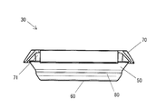
Fig. 14 is a perspective view of a first embodiment of the present invention in a state in which a first member and a second member are assembled. Fig.
Fig. 15 is a perspective view of the first embodiment of the present invention, corresponding to Fig. 14, viewed from the lower side.
Fig. 16 is a front view of the first embodiment of the present invention, corresponding to Fig. 14, in a state in which the first member and the second member are assembled.
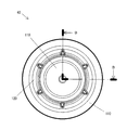
Fig. 17 is a plan view of a first embodiment of the present invention, corresponding to Fig. 14, in a state in which a first member and a second member are assembled.
Fig. 18 is a bottom view of the first embodiment of the present invention, corresponding to Fig. 14, in a state in which the first member and the second member are assembled.
Fig. 19 is a sectional view of a hole plug according to the CC line in Fig. 17 as a first embodiment of the present invention. Fig.
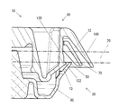
Fig. 20 is a partially enlarged sectional view of Fig. 19 as a first embodiment of the present invention.
21 is a sectional view of a hole plug and a panel as a second embodiment of the present invention.
Fig. 22 is a cross-sectional view of the second embodiment of the present invention, corresponding to Fig. 21, with the hole plug mounted on the panel.
23 is a sectional view of a hole plug and a panel as a third embodiment of the present invention.
Fig. 24 is a sectional view of a third embodiment of the present invention, corresponding to Fig. 23, in a state in which a hole plug is mounted on a panel.
〈홀 플러그(10)〉≪ Hall plug (10) >
도 1~도 19를 이용하여 본 발명의 제 1 실시형태에 대해서 설명한다.A first embodiment of the present invention will be described with reference to Figs. 1 to 19. Fig.
도 1~도 4 중, 10은 본 실시형태에 관한 홀 플러그로서, 차체 등의 패널(20)의 개구(21)에 장착되어 상기 개구(21)를 폐색하는 것이며, 밀봉성 및 차음성을 가진다.1 to 4,
개구(21)는, 도 1에 나타낸 바와 같이, 패널(20)의 표리면, 도면상으로는 상하로 관통하며 원형으로 형성되어 있다.As shown in Fig. 1, the
또한, 패널(20)로서 차량을 예시했지만, 이것에 한정되지 않고, 자동차 이외의 예를 들면 열차나 전차, 항공기, 선박이어도 좋고, 혹은 건물의 바닥이나 벽, 가구나 전자제품이어도 좋다.Although the vehicle is exemplified as the
홀 플러그(10)는, 도 2~4에 나타낸 바와 같이, 크게 나누면 다음의 파트로 구성되어 있다.As shown in Figs. 2 to 4, the
또한, 다음의 (1) 및 (2)에 대해서는 후술한다. The following (1) and (2) will be described later.
(1) 제 1 부재(30)(1) The
(2) 제 2 부재(40)(2) The
또한, 홀 플러그(10)의 파트는 상기한 (1) 및 (2)에 한정되지 않고, 예를 들면 도 21~도 24를 이용하여 후술하겠지만, 1 부재로 구성해도 좋고, 혹은 도시하지 않지만 3 부재 이상으로 구성해도 좋다.Further, the part of the
〈제 1 부재(30)〉≪
제 1 부재(30)는, 도 1~도 9에 나타낸 바와 같이, 후술하는 제 2 부재(40)와 조립할 수 있고, 이 제 2 부재(40)와 협동하여 패널(20)의 개구(21)를 폐색하는 것이다.The
제 1 부재(30)는 적당한 탄성과 강성을 가진다. 예를 들면, 올레핀계 일래스터머(TPO) 등의 열가소성 합성수지에 의해서 일체적으로 성형되어 있다. 또한, 수지로서 올레핀계 일래스터머를 예시했지만, 이것에 한정되지 않는다. 예를 들면, 제 1 부재(30)의 일부, 후술하는 제 1 덮개부(60), 또는 전체를 발포성(發泡性)을 가지는 구성으로 해도 좋다.The
제 1 부재(30)는 크게 나누면 다음의 각부(各部)를 구비한다.The
또한, 다음의 (1)~(5)에 대해서는 후술한다.The following (1) to (5) will be described later.
(1) 제 1 플랜지부(50)(1) The
(2) 제 1 덮개부(60)(2) The
(3) 환형상 플랜지부(70)(3) An annular flange portion (70)
(4) 제 1 측부(80)(제 1 다리부)(4) First side 80 (first leg)
(5) 제 1 공간(90)(5) In the
또한, 제 1 부재(30)의 각부는 상기한 (1)~(5)에 한정되지 않고, 차음성은 저하하지만, 제 1 덮개부(60)와 환형상 플랜지부(70) 중 적어도 어느 일방을 생략하는 것도 가능하다.The
〈제 2 부재(40)〉≪ Second member (40) >
제 2 부재(40)는, 도 1~도 4 및 도 10~도 13에 나타낸 바와 같이, 제 1 부재(30)와 조립할 수 있고, 이 제 1 부재(30)와 협동하여 패널(20)의 개구(21)를 폐색하는 것이다.The
제 2 부재(40)는 제 1 부재(30)와 마찬가지로 적당한 탄성과 강성을 가진다. 예를 들면, 올레핀계 일래스터머(TPO) 등의 열가소성 합성수지에 의해서 일체적으로 성형되어 있다. 또한, 수지로서 올레핀계 일래스터머를 예시했지만, 이것에 한정되지 않는다. 예를 들면, 제 2 부재(40)의 일부, 후술하는 제 2 덮개부(110), 또는 전체를 발포성을 가지는 구성으로 해도 좋다.Like the
제 2 부재(40)는 크게 나누면 다음의 각부를 구비한다.The
또한, 다음의 (1)~(4)에 대해서는 후술한다.The following (1) to (4) will be described later.
(1) 제 2 플랜지부(100)(1) In the
(2) 제 2 덮개부(110)(2) The
(3) 제 2 측부(120)(제 2 다리부)(3) Second side portion 120 (second leg portion)
(4) 제 2 공간(130)(4) the
또한, 제 2 부재(40)의 각부는 상기한 (1)~(4)에 한정되지 않고, 차음성은 저하하지만, 제 2 덮개부(110)를 생략하는 것도 가능하다.In addition, each part of the
〈제 1 플랜지부(50)〉≪
제 1 플랜지부(50)는, 도 1~도 9에 나타낸 바와 같이, 패널(20)에 형성된 개구(21)의 일방측 둘레가장자리, 즉 도 1에 있어서 하측 둘레가장자리에 맞닿는 환형상의 것이다.1 to 9, the
제 1 플랜지부(50)는, 도 9에 나타낸 바와 같이, 하측에서 비스듬한 상측으로 향하여 개방된 우산형으로 형성되고, 그 상단부인 자유단부의 직경을 패널(20)의 개구(21)의 내경보다 크게 설정하고 있다.9, the
또, 제 1 플랜지부(50)는 하측에서 상단부인 자유단부로 향하여 두께를 서서히 감소시킴으로써 휘어지기 쉽게 되어 있다.Further, the
〈제 1 덮개부(60)〉≪
제 1 덮개부(60)는, 도 1~도 9에 나타낸 바와 같이, 제 1 플랜지부(50)와 함께 패널(20)의 개구(21)를 폐색하는 것이다.The
제 1 덮개부(60)는, 도 2 및 도 3에 나타낸 바와 같이 원판형상으로 형성되고, 도 1 및 도 9에 나타낸 바와 같이, 측방에서 보았을 때에 하측으로 향하여 가늘게 된 원추 사다리꼴로 형성되고, 그 가늘게 된 하단부의 외경을 패널(20)의 개구(21)의 내경보다 작게 설정하고 있다.As shown in Figs. 1 and 9, the
제 1 덮개부(60)는, 도 1 및 도 9에 나타낸 바와 같이, 다음의 각부를 구비한다.As shown in Figs. 1 and 9, the
또한, 제 1 덮개부(60)의 각부는 다음의 (1) 및 (2)에 한정되지 않고, 예를 들면 어느 일방 혹은 양방을 생략해도 좋다.Further, each part of the
(1) 후육부(61)(1)
후육부(61)는, 도 1 및 도 9에 나타낸 바와 같이, 제 1 덮개부(60)의 상하의 두께를 두껍게 하여 형성되어 있다. 후육부(61)는 차음성을 향상시키기 위한 것이며, 발포성을 가지는 구성으로 해도 좋다.As shown in Figs. 1 and 9, the
(2) 리브(62)(2)
리브(62)는, 도 1, 도 2, 도 5 및 도 9에 나타낸 바와 같이, 제 1 덮개부(60)의 내면, 즉 상면에서 상측으로 연장되고, 도 5에 나타낸 바와 같이, 반경방향에 있어서 외향으로 방사형상으로 연장되어 있다.As shown in Figs. 1, 2, 5 and 9, the
리브(62)는, 패널(20)의 개구(21)에 대한 제 1 부재(30)의 삽입력을 낮추는 목적으로 형성되어 있다. 즉, 리브(62)는, 리브가 없는 경우와 비교하여, 패널(20)의 개구(21)로의 삽입시에 제 2 부재(40)가 반경방향에 있어서 외향으로 찌그러져서 눌려 퍼짐으로써, 패널(20)에 대한 삽입력이 높아지는 것을 방지하기 때문이다.The
〈환형상 플랜지부(70)〉≪
환형상 플랜지부(70)는, 도 1~도 9에 나타낸 바와 같이, 제 1 플랜지부(50)와 패널(20)의 두께방향, 즉 도 1 및 도 9에 있어서는 상측으로 떨어져서 대향하고, 패널(20)에 형성된 개구(21)의 타방측 둘레가장자리, 즉 도 1에 있어서 상측 둘레가장자리에 맞닿는 환형상의 것이다.As shown in Figs. 1 to 9, the
환형상 플랜지부(70)는, 도 9에 나타낸 바와 같이, 상측에서 비스듬한 하측으로 향하여 개방된 우산형으로 형성되고, 그 하단부인 자유단부의 직경을 패널(20)의 개구(21)의 내경보다 크게 설정하고 있다.9, the
또, 환형상 플랜지(70)부는 제 1 플랜지부(50)에 비해서 그 외경을 크게 설정하고 있다.The outer diameter of the
또한, 환형상 플랜지(70)부는 상측에서 하단부인 자유단부로 향하여 두께를 서서히 감소시킴으로써 휘어지기 쉽게 되어 있다.Further, the
환형상 플랜지부(70)에는, 도 2~도 5, 도 7 및 도 8에 나타낸 바와 같이, 다음의 각부를 구비한다.As shown in Figs. 2 to 5, Fig. 7 and Fig. 8, the
또한, 환형상 플랜지부(70)의 각부는 다음의 (1)에 한정되지 않고, "(1) 절결부(71)"를 생략하고, 예를 들면 원형으로 연속적으로 형성해도 좋다. 또한, 환형상 플랜지부(70)를 연속적으로 형성함으로써 차음성을 향상시킬 수 있는 이점이 있다.The corner portions of the
(1) 절결부(71)(1) The
절결부(71)는, 도 2~도 5, 도 7 및 도 8에 나타낸 바와 같이, 환형상 플랜지부(70)를 반경방향으로 잘라 나누는 것이며, 복수 개, 예를 들면 120도 간격으로 3개 형성되어 있다. 또한, 절결부(71)의 개수로서 3개를 예시했지만, 이것에 한정되지 않고, 예를 들면 90도 간격으로 4개 형성하거나, 혹은 등간격으로 5개 이상 형성해도 좋다.2 to 5, 7, and 8, the
〈제 1 측부(80)〉<
제 1 측부(80)는, 도 1~도 9에 나타낸 바와 같이, 제 1 플랜지부(50), 제 1 덮개부(60) 및 환형상 플랜지부(70)를 서로 연결하는 것이며, 원통형으로 형성되어 있다.The
제 1 측부(80)는, 도 9에 나타낸 바와 같이, 제 1 덮개부(60)의 상측 가장자리부에서 되접은 형상으로 하측으로 연장되고, 상측으로 향하여 되접은 형상으로 더 연장되며, 환형상 플랜지부(70)에 연속하고 있다. 또, 제 1 측부(80)의 높이의 도중에는 제 1 플랜지부(50)가 연속하고 있다.As shown in Fig. 9, the
제 1 측부(80)는, 제 2 부재(40)와의 관계에 있어서, 제 1 덮개부(60)에서 제 2 부재(40)의 후술하는 제 2 덮개부(110)로 향하여 연장되어 형성되고, "제 1 다리부"로서 기능한다.The
또한, 제 1 측부(80)를 제 1 덮개부(60)에서 연장하여 형성시켰지만, "제 1 다리부"로서는 이것에 한정되지 않고, 예를 들면 제 1 플랜지부(50)에서 연장하여 형성하거나 혹은 제 2 부재(40)의 후술하는 제 2 플랜지부(100)로 향하여 연장하여 형성시켜도 좋다.Although the
또, 제 1 측부(80)는 원통형으로 형성했지만, "제 1 다리부"로서는 이것에 한정되지 않고, 판형상으로 형성해도 좋다.Although the
제 1 측부(80)는 그 외경을 패널(20)의 개구(21)의 내경에 거의 일치시키고 있다.The
제 1 측부(80)에는, 도 2, 도 5 및 도 9에 나타낸 바와 같이, 다음의 각부를 구비한다.As shown in Figs. 2, 5, and 9, the
또한, 제 1 측부(80)의 각부는 다음의 (1) 및 (2)에 한정되지 않고, 제 1 부재(30)와 제 2 부재(40)의 조립성은 저하하지만, 예를 들면 (1)을 생략하는 것도 가능하다.The
(1) 가이드 홈(81)(1) Guide groove (81)
가이드 홈(81)은, 도 2, 도 5 및 도 9에 나타낸 바와 같이, 제 1 측부(80)의 내주면에 형성되고, 제 2 부재(40)와 조립할 때에 그 후술하는 볼록형상의 가이드 돌기(121)를 안내하기 위한 것이다.2, 5, and 9, the
가이드 홈(81)은 제 1 측부(80)의 내주면에 오목형상으로 형성되고, 상단부가 개방되며 하단부가 막다른 곳에 형성되어 있다.The
또한, 제 1 부재(30) 측에 오목형상의 가이드 홈(81)을 형성하고, 제 2 부재(40) 측에 볼록형상의 가이드 돌기(121)을 형성했지만, 이것에 한정되지 않고, 도시하지 않지만, 제 1 부재(30) 측에 볼록형상의 가이드 돌기를 형성하고, 제 2 부재(40) 측에 오목형상의 가이드 홈을 형성해도 좋다.Although the
가이드 홈(81)은 복수 개, 예를 들면 60도 간격으로 합계 6개 형성되어 있다.A total of six
또한, 가이드 홈(81)의 개수로서 6개를 예시했지만, 이것에 한정되지 않고, 단수, 2~5개 혹은 7개 형성해도 좋다.The number of the
(2) 로크구멍(82)(피걸림고정부)(2) The lock hole 82 (engaged portion)
로크구멍(82)은, 도 2, 도 5 및 도 9에 나타낸 바와 같이, 가이드 홈(81)의 하부에 위치하며, 제 1 측부(80)를 내외로 관통하는 사각형으로 형성되어 있다. 로크구멍(82)에는 제 2 부재(40)의 후술하는 로크돌조(122)가 끼워짐으로써, 제 1 부재(30)와 제 2 부재(40)가 조립상태로 로크된다. 로크구멍(82)은 제 1 부재(30)와 제 2 부재(40)를 연결시키는 "피걸림고정부"로서 기능하고, 이것에 대해서 로크돌조(122)는 "걸림고정부"로 기능한다.2, 5, and 9, the
또한, 로크구멍(82)을 구멍형상으로 형성했으나, 도시하지 않지만, 예를 들면 오목형상으로 형성해도 좋다.Further, although the
또, 제 1 부재(30) 측에 로크구멍(82)을 형성하고, 제 2 부재(40) 측에 로크돌조(122)를 형성했으나, 이것에 한정되지 않고, 도시하지 않지만, 예를 들면 제 1 부재(30) 측에 로크돌조를 형성하고, 제 2 부재(40) 측에 로크구멍을 형성해도 좋다.Although the
〈제 1 공간(90)〉<
제 1 공간(90)은, 도 2, 도 5 및 도 9에 나타낸 바와 같이, 제 1 덮개부(60) 및 제 1 측부(80)에 의해서 둘러싸인 내측에 위치하며, 상측으로 향하여 개방된다. 제 1 공간(90)의 내측에는 리브(62)가 위치한다.2, 5, and 9, the
〈제 2 플랜지부(100)〉≪
제 2 플랜지부(100)는, 도 1~도 4 및 도 10~도 13에 나타낸 바와 같이, 패널(20)에 형성된 개구(21)의 타방측 둘레가장자리, 즉 도 1에 있어서 상측 둘레가장자리에 맞닿는 환형상의 것이다.As shown in Figs. 1 to 4 and Figs. 10 to 13, the
제 2 플랜지부(100)는, 도 13에 나타낸 바와 같이, 상측에서 비스듬한 하측으로 향하여 개방된 우산형으로 형성되고, 그 하단부인 자유단부의 직경을 패널(20)의 개구(21)의 내경보다 크게 설정하고 있다.13, the
또, 제 2 플랜지부(100)는 상측에서 하단부인 자유단부로 향하여 두께를 서서히 감소시킴으로써 휘어지기 쉽게 되어 있다.In addition, the
한편, 제 2 플랜지부(100)는, 도 1 및 도 19에 나타낸 바와 같이, 제 1 부재(30)의 제 1 플랜지부(50)에 비해서 그 외경을 크게 설정하고 있다. 반대로 말하면, 제 1 플랜지부(50)의 외경을 제 2 플랜지부(100)보다 작게 설정함으로써, 패널(20)의 개구(21)에 대한 삽입성을 향상시키고 있다.On the other hand, as shown in Figs. 1 and 19, the
또, 제 2 플랜지부(100)는, 제 1 부재(30)의 환형상 플랜지부(70)에 비해서 그 외경을 크게 설정하고 있다.The outer diameter of the
또한, 제 2 플랜지부(100)는, 도 1 및 도 19에 나타낸 바와 같이, 제 1 부재(30)와 제 2 부재(40)의 조립상태 및 패널(20)로의 장착상태에 있어서, 환형상 플랜지부(70)와 상하로 떨어져서 위치함으로써, 양자 간에 제 1 간극(12)이 발생하도록 하고 있다. 제 1 간극(12)을 발생시킴으로써, 제 2 플랜지부(100)와 환형상 플랜지부(70)를 서로 밀착시킨 경우에 비해서 차음성을 향상시킬 수 있었다. 그렇기 때문에, 제 2 플랜지부(100)와 환형상 플랜지부(70)는 접하지 않는 것이 바람직하다. 이와 같이, 제 2 플랜지부(100)와 환형상 플랜지부(70)가 접하지 않고, 즉 떨어져 있음으로써 제 2 부재(40)의 진동이 제 1 부재(30)로 전달되지 않고, 또 반대도 마찬가지로 제 1 부재(30)의 진동이 제 2 부재(40)로 전달되지 않는 효과가 있다.1 and 19, in the assembled state of the
〈제 2 덮개부(110)〉≪
제 2 덮개부(110)는, 도 1~도 3, 도 10, 도 12 및 도 13에 나타낸 바와 같이, 제 2 플랜지부(100)와 함께 패널(20)의 개구(21)를 폐색하는 것이다.The
제 2 덮개부(110)는, 도 2 및 도 3에 나타낸 바와 같이, 원판형상으로 형성되고, 도 1 및 도 13에 나타낸 바와 같이, 측방에서 보았을 때에 상측으로 향하여 가늘게 된 원추 사다리꼴로 형성되어 있다.As shown in Figs. 1 and 13, the
제 2 플랜지부(100) 및 제 2 덮개부(110)는, 제 1 부재(30)에 대해서는 "폐색부"를 구성한다.The
제 2 덮개부(110)는, 도 1 및 도 13에 나타낸 바와 같이, 다음의 각부를 구비한다.As shown in Figs. 1 and 13, the
또한, 제 2 덮개부(110)의 각부는 다음의 (1)에 한정되지 않고, 차음성은 저하하지만, 예를 들면 (1)을 생략해도 좋다.Further, the corner portions of the
(1) 후육부(111)(1)
후육부(111)는, 도 1 및 도 13에 나타낸 바와 같이, 제 2 덮개부(110)의 상하의 두께를 두껍게 하여 형성되어 있다. 후육부(111)는 차음성을 향상시키기 위한 것이며, 발포성을 가지는 구성으로 해도 좋다.As shown in Figs. 1 and 13, the
〈제 2 측부(120)〉≪
제 2 측부(120)는, 도 1~도 4 및 도 10~도 13에 나타낸 바와 같이, 제 2 플랜지부(100) 및 제 2 덮개부(110)를 서로 연결하는 것이며, 원통형으로 형성되어 있다.The
제 2 측부(120)는, 도 13에 나타낸 바와 같이, 제 2 덮개부(110)의 하측 가장자리부에서 되접은 형상으로 상측으로 향하여 연장되고, 제 2 플랜지부(100)에 연속하고 있다.As shown in Fig. 13, the
제 2 측부(120)는, 제 1 부재(30)와의 관계에 있어서, 제 2 덮개부(110)에서 제 1 부재(30)의 제 1 덮개부(60)로 향하여 연장되어 형성되고, "제 2 다리부"로서 기능한다.The
또한, 제 2 측부(120)를 제 2 덮개부(110)에서 연장하여 형성시켰지만, "제 2 다리부"로서는 이것에 한정되지 않고, 예를 들면 제 2 플랜지부(100)에서 연장하여 형성하거나 혹은 제 1 부재(30)의 제 1 플랜지부(50)로 향하여 연장하여 형성시켜도 좋다.Although the
또, 제 2 측부(120)는 원통형으로 형성했지만, "제 2 다리부"로서는 이것에 한정되지 않고, 판형상으로 형성해도 좋다.In addition, although the
제 2 측부(120)는 그 외경을 제 1 측부(80)의 내경에 거의 일치시키고 있다.The
제 2 측부(120)에는, 도 3 및 도 11~도 13에 나타낸 바와 같이, 다음의 각부를 구비한다.As shown in Figs. 3 and 11 to 13, the
또한, 제 2 측부(120)의 각부는 다음의 (1) 및 (2)에 한정되지 않고, 제 1 부재(30)와 제 2 부재(40)의 조립성은 저하하지만, 예를 들면 (1)을 생략하는 것도 가능하다.The angles of the
(1) 가이드 돌기(121)(1) Guide protrusion (121)
가이드 돌기(121)는, 도 3 및 도 11~도 13에 나타낸 바와 같이, 제 2 측부(120)의 외주에 상하로 긴 볼록형상으로 형성되며, 제 1 부재(30)의 가이드 홈(81)에 끼워지는 것이다. 또, 가이드 돌기(121)는, 제 1 부재(30)와 제 2 부재(40)의 조립상태(도 1 및 도 19)에 있어서, 제 1 부재(30)의 가이드 홈(81)에 접하지 않는 것이 바람직하다. 즉, 가이드 돌기(121)와 가이드 홈(81)끼리가 접하지 않고, 즉 떨어져 있음으로써 제 2 부재(40)의 진동이 제 1 부재(30)로 전달되지 않고, 또 반대도 마찬가지로 제 1 부재(30)의 진동이 제 2 부재(40)로 전달되지 않는 효과가 있다.3 and 11 to 13, the
(2) 로크돌조(122)(걸림고정부)(2) Locking protrusion 122 (locking protrusion)
로크돌조(122)는 가이드 돌기(121)의 하단부에 돌조형상으로 형성되고, 제 1 부재(30)의 가이드 홈(81) 내에 위치하여 그 "피걸림고정부"로서 기능하는 로크구멍(82)에 끼워지는 것이며, "걸림고정부"로서 기능한다. 또, 로크돌조(122)는, 도 19에 나타낸 바와 같이, 로크구멍(82)을 통해서 외향하고, 즉 패널(20) 측으로 돌출한다. 로크돌조(122)는, 제 1 부재(30)와 제 2 부재(40)의 조립상태에 있어서, 패널(20)의 개구(21)에 맞춰서 장착했을 때에, 패널(20)의 이면에 끼워 맞춰진다. 이때, 제 1 부재(30)의 제 1 플랜지부(50)도 패널(20)의 이면에 걸어맞춰지기 때문에, 로크돌조(122)와 제 1 플랜지부(50)의 사이에는 제 2 간극(13)이 발생한다. 이와 같이, 로크돌조(122)와 제 1 플랜지부(50)가 접하지 않고, 즉 떨어져 있음으로써 제 2 부재(40)의 진동이 제 1 부재(30)로 전달되지 않고, 또 반대도 마찬가지로 제 1 부재(30)의 진동이 제 2 부재(40)로 전달되지 않는 효과가 있기 때문에, 제 2 간극(13)에 의해서 차음성을 향상시킬 수 있다.The
〈제 2 공간(130)〉≪
제 2 공간(130)은, 도 3, 도 12 및 도 13에 나타낸 바와 같이, 제 2 덮개부(110) 및 제 2 측부(120)에 의해서 둘러싸인 내측에 위치하며, 하측으로 향하여 개방된다.The
제 2 공간(130)은 제 1 공간(90)과 상하로 대향하고, 양자 간에는, 도 1 및 도 19에 나타낸 바와 같이, 밀폐된 공기층(11)이 형성된다. 공기층(11)은 차음성을 향상시키기 위한 것이다. 또한, 공기층(11)을 형성함으로써, 특히 사람이 듣기 쉬운 주파수대, 예를 들면 2,500~5,500Hz에 있어서의 차음성을 공기층(11)이 없는 것에 비해서 대폭으로 향상시킬 수 있었다.The
〈제 1 부재(30)와 제 2 부재(40)의 조립〉<Assembling of
다음으로, 상기한 구성을 가지는 제 1 부재(30)와 제 2 부재(40)는, 도 1 및 도 14~도 19에 나타낸 바와 같이, 출하시에 서로 조립하여 조립상태로 출하함으로써 납품시 등의 취급을 용이하게 할 수 있다.Next, as shown in Figs. 1 and 14 to 19, the
또한, 제 1 부재(30)와 제 2 부재(40)를 출하시에 조립했지만, 이것에 한정되지 않고, 납품시 등의 취급성은 저하하지만, 출하 후에 조립하도록 해도 좋다.In addition, although the
조립할 때에는, 제 2 부재(40)의 가이드 돌기(121)를 제 1 부재(30)의 가이드 홈(81)의 개방면에 맞춰서 끼워 넣는다. 가이드 돌기(121)를 더 압입하면, 그 로크돌조(122)에 압압되어 가이드 홈(81)이 휘면서 로크구멍(82)에 짤깍하고 끼워 넣어진다. 이것에 의해서, 제 1 부재(30)와 제 2 부재(40)는 조립상태로 로크된다.The
조립상태에 있어서는, 도 1 및 도 19에 나타낸 바와 같이, 제 1 부재(30)와 제 2 부재(40)의 사이에 밀폐된 공기층(11)이 형성된다.In the assembled state, as shown in Figs. 1 and 19, an
〈패널(20)로의 장착〉<Mounting on
조립상태로 로크된 홀 플러그(10)를, 도 1에 나타낸 바와 같이, 그 제 1 부재(30) 측부터 패널(20)의 개구(21)에 맞춰서 삽입한다.The hole plug 10 locked in the assembled state is inserted into the
제 1 부재(30) 측부터 삽입하면, 그 제 1 플랜지부(50)가 개구(21)의 내연부에 압압됨으로써 축경(縮徑)하고, 이 개구(21)를 통과한 후 수지의 탄성에 의해서 복원되어 패널(20)의 개구(21)의 일방측 둘레가장자리, 예를 들면 하측 둘레가장자리에 탄성적으로 맞닿는다. 또, 동시에 제 2 부재(40)의 제 2 플랜지부(100)가 제 1 부재(30)의 환형상 플랜지부(70)를 사이에 두고 패널(20)의 개구(21)의 타방측 둘레가장자리, 예를 들면 상측 둘레가장자리에 탄성적으로 맞닿는다.The
패널(20)의 개구(21)는, 하측에서는 제 1 부재(30)의 제 1 덮개부(60) 및 제 1 플랜지부(50)에 의해서 주로 폐색되고, 또 상측에서 제 2 부재(40)의 제 2 덮개부(110) 및 제 2 플랜지부(100)에 의해서 주로 폐색된다. 그 결과, 홀 플러그(10)에 의해서 패널(20)의 개구(21)를 상하방향으로 폐색할 수 있다.The
또, 제 1 부재(30)의 제 1 플랜지부(50)가 패널(20)의 개구(21)의 하측 둘레가장자리에 탄성적으로 맞닿고, 제 2 부재(40)의 제 2 플랜지부(100)가 제 1 부재(30)의 환형상 플랜지부(70)를 사이에 두고 패널(20)의 개구(21)의 상측 둘레가장자리에 탄성적으로 맞닿음으로써, 패널(20)이 홀 플러그(10)에 의해서 상하방향에서 협지되어 홀 플러그(10)가 패널(20)의 개구(21)에 유지된다.The
또한, 제 1 부재(30)의 제 1 플랜지부(50)가 패널(20)의 개구(21)의 하측 둘레가장자리에 탄성적으로 맞닿고, 제 2 부재(40)의 제 2 플랜지부(100)가 제 1 부재(30)의 환형상 플랜지부(70)를 사이에 두고 패널(20)의 개구(21)의 상측 둘레가장자리에 탄성적으로 맞닿음으로써, 밀봉 효과 혹은 지수 효과를 발휘한다.The
또, 밀봉 효과에 의해서, 패널(20)의 개구(21)를 통과한 소리 및 진동의 전달을 저감 내지는 차단할 수 있다.In addition, the transmission of sound and vibration through the
또한, 제 1 부재(30)와 제 2 부재(40)의 사이에 형성된 밀폐된 공기층(11)에 의해서, 홀 플러그(10)에 전달된 소리 및 진동을 저감 내지는 차단할 수 있다.It is also possible to prevent or reduce sound and vibration transmitted to the
또, 제 1 부재(30)의 제 1 덮개부(60)에 후육부(61)를 형성하고, 제 2 부재(40)의 제 2 덮개부(110)에 후육부(111)를 형성하고 있기 때문에, 홀 플러그(10)에 전달된 소리 및 진동을 저감 내지는 차단할 수 있다.A
또한, 제 2 플랜지부(100)는 환형상 플랜지부(70)와 상하로 떨어져서 위치하기 때문에 양자간에 제 1 간극(12)이 발생한다. 제 1 간극(12)이 발생함으로써, 제 2 플랜지부(100)와 환형상 플랜지부(70)를 서로 밀착시킨 경우에 비해서 차음성을 향상시킬 수 있었다.Also, since the
한편, 제 1 부재(30)의 일부, 예를 들면 제 1 덮개부(60), 또는 전체를 발포성을 가지는 구성으로 하고, 제 2 부재(40)의 일부, 예를 들면 제 2 덮개부(110), 또는 전체를 발포성을 가지는 구성으로 함으로써 홀 플러그(10)에 전달된 소리 및 진동을 저감 내지는 차단할 수 있다.On the other hand, a part of the
〈도 21 및 도 22를 이용한 제 2 실시형태의 설명〉<Description of Second Embodiment Using FIGS. 21 and 22>
도 21 및 도 22를 이용하여 본 발명의 제 2 실시형태에 대해서 설명한다.A second embodiment of the present invention will be described with reference to Figs. 21 and 22. Fig.
본 실시형태의 특징은 홀 플러그(200)를 1 부재로 구성한 점이다.The feature of the present embodiment is that the
본 실시형태에 의하면, 홀 플러그(200)를 1 부재로 함으로써 구조 및 제조를 간편하게 할 수 있는 이점이 있다.According to the present embodiment, there is an advantage that the structure and manufacturing can be simplified by making the hole plug 200 a single member.
홀 플러그(200)는 적당한 탄성과 강성을 가진다, 예를 들면 올레핀계 일래스터머(TPO) 등의 열가소성 합성수지에 의해서 일체적으로 성형되어 있다. 또한, 수지로서 올레핀계 일래스터머를 예시했지만, 이것에 한정되지 않는다. 예를 들면, 홀 플러그(200)의 일부, 후술하는 제 1 덮개부(230), 또는 전체를 발포성을 가지는 구성으로 해도 좋다.The
홀 플러그(200)는, 도 21 및 도 22에 나타낸 바와 같이, 크게 나누면 다음의 각부를 구비한다.As shown in Figs. 21 and 22, the
(1) 제 1 플랜지부(220)(1) The
제 1 플랜지부(220)는, 도 21 및 도 22에 나타낸 바와 같이, 패널(210)에 형성된 개구(211)의 일방측 둘레가장자리, 예를 들면 상측 둘레가장자리에 맞닿는 환형상의 것이다.21 and 22, the
(2) 제 1 덮개부(230)(2) The
제 1 덮개부(230)는, 도 21 및 도 22에 나타낸 바와 같이, 제 1 플랜지부(220)와 함께 개구(211)를 폐색하는 것이다.The
제 1 덮개부(230)에는 그 상하의 두께를 두껍게 하여 후육부(231)를 형성하고 있다. 후육부(231)는 차음성을 향상시키기 위한 것이며, 발포성을 가지는 구성으로 해도 좋다.The
(3) 폐색부(240)(3)
폐색부(240)는, 도 21 및 도 22에 나타낸 바와 같이, 개구(211)의 타방측 둘레가장자리, 예를 들면 하측 둘레가장자리에 걸어맞춰지고, 제 1 플랜지부(220) 또는 제 1 덮개부(230)와의 사이에서 소정의 공간(250)을 구비하여 개구(211)를 폐색하는 것이다.The closing
공간(250)에 의해서, 이 공간(250) 내에 형성되는 공기층에 의해서 소리 및 진동의 전달을 경감 내지는 차단하고, 차음성을 향상시킬 수 있다.By the air space formed in the
폐색부(240)는, 도 21 및 도 22에 나타낸 바와 같이, 제 1 덮개부(230)에서 연장되어 형성된 다리부(260)와, 이 다리부(260)에서 돌출되며 개구(211)의 타방측 둘레가장자리, 예를 들면 하측 둘레가장자리에 걸어맞춰지는 돌조부(270)로 구성되어 있다.21 and 22, the closing
또, 공간(250)의 하측 하면에는 밀폐부(280)가 형성되어 있다. 밀폐부(280)는 공간(250)을 밀폐함으로써 차음성을 향상시키기 위한 것이다. 밀폐부(280)는 별체로서 나중에 조립하도록 했지만, 이것에 한정되지 않고 일체적으로 성형하도록 해도 좋다.A sealing
〈도 23 및 도 24를 이용한 제 3 실시형태의 설명〉≪ Description of the third embodiment using Fig. 23 and Fig.
도 23 및 도 24를 이용하여 본 발명의 제 3 실시형태에 대해서 설명한다.A third embodiment of the present invention will be described with reference to Figs. 23 and 24. Fig.
본 실시형태는 공간(350)을 밀폐된 공기층으로 할 수 있도록 한 점이다.In this embodiment, the
본 실시형태에 의하면, 밀폐된 공기층보다 차음성을 더 향상시킬 수 있는 이점이 있다.According to the present embodiment, there is an advantage that the car sound can be further improved as compared with the closed air layer.
홀 플러그(300)는 적당한 탄성과 강성을 가진다. 예를 들면 올레핀계 일래스터머(TPO) 등의 열가소성 합성수지에 의해서 일체적으로 성형되어 있다. 또한, 수지로서 올레핀계 일래스터머를 예시했지만, 이것에 한정되지 않는다. 예를 들면, 홀 플러그(300)의 일부, 후술하는 제 1 덮개부(330) 및 제 2 덮개부(370), 또는 전체를 발포성을 가지는 구성으로 해도 좋다.The
홀 플러그(300)는, 먼저 도 21 및 도 22를 이용하여 설명한 제 2 실시형태에 관한 홀 플러그(200)와 마찬가지로, 도 23 및 도 24에 나타낸 바와 같이, 크게 나누면 다음의 구성을 구비한다.As shown in Figs. 23 and 24, the
(1) 제 1 플랜지부(320)(1) The
제 1 플랜지부(320)는, 도 23 및 도 24에 나타낸 바와 같이, 패널(310)에 형성된 개구(311)의 일방측 둘레가장자리, 예를 들면 상측 둘레가장자리에 맞닿는 환형상의 것이다.As shown in Figs. 23 and 24, the
(2) 제 1 덮개부(330) (2) The
제 1 덮개부(330)는, 도 23 및 도 24에 나타낸 바와 같이, 제 1 플랜지부(320)와 함께 개구(311)를 폐색하는 것이다.The
제 1 덮개부(330)에는 그 상하의 두께를 두껍게 하여 후육부(331)를 형성하고 있다. 후육부(331)는 차음성을 향상시키기 위한 것이며, 발포성을 가지는 구성으로 해도 좋다.The
(3) 폐색부(340)(3)
폐색부(340)는, 도 23 및 도 24에 나타낸 바와 같이, 개구(311)의 타방측 둘레가장자리, 예를 들면 하측 둘레가장자리에 걸어맞춰지고, 제 1 플랜지부(320) 또는 제 1 덮개부(330)와의 사이에서 소정의 공간(350)을 구비하여 개구(311)를 폐색하는 것이다.The closing
〈폐색부(340)〉<
폐색부(340)는, 도 23 및 도 24에 나타낸 바와 같이, 크게 나누면 다음의 각부를 구비한다.As shown in Fig. 23 and Fig. 24, the closing
(1) 제 2 플랜지부(360)(1) the
제 2 플랜지부(360)는, 도 23 및 도 24에 나타낸 바와 같이, 개구(311)의 타방측 둘레가장자리, 예를 들면 하측 둘레가장자리에 맞닿는 환형상의 것이다.As shown in Figs. 23 and 24, the
(2) 제 2 덮개부(370)(2) The
제 2 덮개부(370)는 제 2 플랜지부(360)와 협동하여 개구(311)를 폐색하는 것이다.The
제 2 덮개부(370)에는 그 상하의 두께를 두껍게 하여 후육부(371)를 형성하고 있다. 후육부(371)는 차음성을 향상시키기 위한 것이며, 발포성을 가지는 구성으로 해도 좋다.
〈제 1 실시형태〉
10 : 홀 플러그 11 : 공기층
12 : 제 1 간극 13 : 제 2 간극
20 : 패널 21 : 개구
30 : 제 1 부재 40 : 제 2 부재
50 : 제 1 플랜지부 60 : 제 1 덮개부
61 : 후육부 62 : 리브
70 : 환형상 플랜지부 71 : 절결부
80 : 제 1 측부(제 1 다리부) 81 : 가이드 홈
82: 로크구멍(피걸림고정부) 90 : 제 1 공간
100 : 제 2 플랜지부 110 : 제 2 덮개부
111 : 후육부 120 : 제 2 측부(제 2 다리부)
121 : 가이드 돌기 122 : 로크돌조(걸림고정부)
130 : 제 2 공간
〈제 2 실시형태〉
200 : 홀 플러그 210 : 패널
211 : 개구 220 : 제 1 플랜지부
230 : 제 1 덮개부 231 : 후육부
240 : 폐색부 250 : 공간
260 : 다리부 270 : 돌조부
280 : 밀폐부
〈제 3 실시형태〉
300 : 홀 플러그 310 : 패널
311 : 개구 320 : 제 1 플랜지부
330 : 제 1 덮개부 331 : 후육부
340 : 폐색부 350 : 공간
360 : 제 2 플랜지부 370 : 제 2 덮개부
371 : 후육부≪ First Embodiment >
10: Hall plug 11: Air layer
12: first gap 13: second gap
20: panel 21: opening
30: first member 40: second member
50: first flange portion 60: first cover portion
61: thick portion 62: rib
70: annular flange portion 71: cutout portion
80: first side (first leg) 81: guide groove
82: lock hole (to-be-locked) 90: first space
100: second flange portion 110: second cover portion
111: thicker portion 120: second side portion (second leg portion)
121: guide protrusion 122: lock protrusion (stopping portion)
130: the second space
≪ Second Embodiment >
200: Hall plug 210: Panel
211: aperture 220: first flange portion
230: first lid part 231: thick part
240: closing part 250: space
260: leg portion 270: protruding portion
280:
≪ Third Embodiment >
300: Hall plug 310: Panel
311: opening 320: first flange portion
330: first lid part 331: thick part
340: obstruction part 350: space
360: second flange portion 370: second cover portion
371: thickening
Claims (9)
상기 제 1 플랜지부와 함께 상기 개구를 폐색하는 제 1 덮개부와,
상기 개구의 타방측 둘레가장자리에 걸어맞춰지고, 상기 제 1 플랜지부 또는 상기 제 1 덮개부와의 사이에서 소정의 공간을 구비하여 상기 개구를 폐색하는 폐색부를 구비하고 있는 것을 특징으로 하는 홀 플러그.
An annular first flange portion abutting one peripheral edge of the opening formed in the panel,
A first lid portion that closes the opening together with the first flange portion,
And a blocking portion which is engaged with the other peripheral edge of the opening and has a predetermined space between the first flange portion and the first cover portion to close the opening.
상기 폐색부는,
상기 개구의 타방측 둘레가장자리에 맞닿는 환형상의 제 2 플랜지부와,
상기 제 2 플랜지부와 협동하여 상기 개구를 폐색하는 제 2 덮개부로 이루어지는 것을 특징으로 하는 홀 플러그.
The method according to claim 1,
The occlusion unit includes:
An annular second flange portion abutting the other peripheral edge of the opening,
And a second lid portion cooperating with the second flange portion to close the opening.
상기 제 1 플랜지부와 상기 제 1 덮개부를 구비한 부재와,
상기 제 2 플랜지부와 상기 제 2 덮개부를 구비한 부재는,
각각 다른 제 1 부재와 제 2 부재로 구성되고,
상기 양 부재는 멀어지는 방향으로 서로 걸어맞추는 것이 가능한 걸림고정부와 피걸림고정부를 구비한 것을 특징으로 하는 홀 플러그.
The method of claim 2,
A member having the first flange portion and the first lid portion,
Wherein the member having the second flange portion and the second lid portion,
Each of which is composed of a first member and a second member,
And both the engagement members are engaged with each other in a direction in which the two members are separated from each other.
상기 걸림고정부와 상기 피걸림고정부는,
상기 제 1 플랜지부 또는 상기 제 1 덮개부, 혹은 상기 제 2 플랜지부 또는 상기 제 2 덮개부에서 타방의 플랜지부 또는 덮개부로 향하여 연장되어 형성된 다리부에 형성되며, 적어도 어느 일방이 상기 제 1 플랜지부와 상기 제 2 플랜지부 중 어느 일방과 협동하여 패널을 협지(挾持)하는 것을 특징으로 하는 홀 플러그.
The method of claim 3,
The engagement and retraction portions and the engagement-
And a leg portion formed to extend from the first flange portion or the first lid portion or the second flange portion or the second lid portion toward the other flange portion or the lid portion, And the second flange portion cooperates with one of the first flange portion and the second flange portion to sandwich the panel.
상기 제 1 부재 또는 상기 제 2 부재의 상기 플랜지부, 혹은 상기 제 1 부재 또는 상기 제 2 부재의 상기 덮개부에서는, 타방의 플랜지부 또는 덮개부로 향하여 연장되어 형성된 다리부가 형성되며,
적어도 어느 일방의 상기 다리부에는, 상기 제 1 플랜지부와 상기 제 2 플지부 중 어느 일방과 협동하여 상기 패널을 협지하는 환형상 플랜지부를 구비한 것을 특징으로 하는 홀 플러그.The method of claim 3,
A leg portion formed to extend toward the other flange portion or the lid portion is formed in the flange portion of the first member or the second member or the lid portion of the first member or the second member,
Wherein at least one of the leg portions has an annular flange portion that cooperates with either one of the first flange portion and the second flange portion to sandwich the panel.
상기 제 1 부재 또는 상기 제 2 부재의 상기 플랜지부, 혹은 상기 제 1 부재 또는 상기 제 2 부재의 상기 덮개부에서는, 타방의 플랜지부 또는 덮개부로 향하여 연장되어 형성된 다리부가 형성되며,
적어도 어느 일방의 상기 다리부에는, 상기 제 1 플랜지부와 상기 제 2 플지부 중 어느 일방과 협동하여 상기 패널을 협지하는 환형상 플랜지부를 구비한 것을 특징으로 하는 홀 플러그.
The method of claim 4,
A leg portion formed to extend toward the other flange portion or the lid portion is formed in the flange portion of the first member or the second member or the lid portion of the first member or the second member,
Wherein at least one of the leg portions has an annular flange portion that cooperates with either one of the first flange portion and the second flange portion to sandwich the panel.
상기 제 1 플랜지부와 상기 제 2 플랜지부 중 어느 일방은,
타방의 플랜지부보다 작은 직경인 것을 특징으로 하는 홀 플러그.
The method according to any one of claims 3 to 6,
Wherein either one of the first flange portion and the second flange portion is provided with a through-
And a diameter smaller than that of the other flange portion.
상기 피걸림고정부는,
상기 제 1 부재 또는 상기 제 2 부재 중 어느 일방의 다리부에 형성된 개구이며,
상기 걸림고정부는,
타방의 다리부에 형성되며,
상기 다리부에 의해서 둘러싸인 내부에 위치하는 공간을 통과하는 구성인 것을 특징으로 하는 홀 플러그.
The method according to any one of claims 3 to 6,
The pawl fixing portion
An opening formed in a leg portion of either the first member or the second member,
The engaging /
And is formed on the other leg portion,
And a space which is surrounded by the leg portion and which is located inside.
상기 제 1 덮개부와 상기 제 2 덮개부 중 적어도 어느 일방은,
발포성(發泡性)을 가지는 구성을 포함하는 것을 특징으로 하는 홀 플러그.The method according to any one of claims 2 to 6,
At least one of the first lid portion and the second lid portion,
Wherein the hole plug has a configuration having foamability.
Applications Claiming Priority (2)
| Application Number | Priority Date | Filing Date | Title |
|---|---|---|---|
| JPJP-P-2017-033263 | 2017-02-24 | ||
| JP2017033263A JP2018138794A (en) | 2017-02-24 | 2017-02-24 | Hole plug |
Publications (1)
| Publication Number | Publication Date |
|---|---|
| KR20180098141A true KR20180098141A (en) | 2018-09-03 |
Family
ID=63450722
Family Applications (1)
| Application Number | Title | Priority Date | Filing Date |
|---|---|---|---|
| KR1020180018537A Ceased KR20180098141A (en) | 2017-02-24 | 2018-02-14 | Hole plug |
Country Status (2)
| Country | Link |
|---|---|
| JP (1) | JP2018138794A (en) |
| KR (1) | KR20180098141A (en) |
Families Citing this family (2)
| Publication number | Priority date | Publication date | Assignee | Title |
|---|---|---|---|---|
| US11408509B2 (en) * | 2019-08-16 | 2022-08-09 | Illinois Tool Works Inc. | Sealing plug |
| CN113276963A (en) * | 2021-05-27 | 2021-08-20 | 奇瑞汽车股份有限公司 | Plugging piece and vehicle |
Citations (2)
| Publication number | Priority date | Publication date | Assignee | Title |
|---|---|---|---|---|
| JPS4899836A (en) | 1972-04-03 | 1973-12-17 | ||
| JP2013221547A (en) | 2012-04-13 | 2013-10-28 | Nifco Inc | Hole plug for two-sided seal |
Family Cites Families (9)
| Publication number | Priority date | Publication date | Assignee | Title |
|---|---|---|---|---|
| JPS5835578Y2 (en) * | 1978-12-12 | 1983-08-10 | 日産自動車株式会社 | plug |
| JPS56138265U (en) * | 1980-03-19 | 1981-10-20 | ||
| JPH0432525Y2 (en) * | 1987-09-07 | 1992-08-05 | ||
| DE4421012A1 (en) * | 1994-06-20 | 1995-12-21 | Teroson Gmbh | Acoustically effective plastisols |
| DE20209513U1 (en) * | 2002-06-19 | 2002-08-29 | TRW Automotive Electronics & Components GmbH & Co. KG, 78315 Radolfzell | cap |
| DE102006007914B4 (en) * | 2006-02-16 | 2008-02-28 | Itw Automotive Products Gmbh & Co. Kg | Sealing plug with pressure compensation chamber |
| JP5352431B2 (en) * | 2009-11-10 | 2013-11-27 | 株式会社ニフコ | Hole seal structure |
| US9045932B2 (en) * | 2012-04-05 | 2015-06-02 | Allied Moulded Products, Inc. | Hole seal |
| DE102015102169B4 (en) * | 2015-02-16 | 2016-08-25 | Trw Automotive Electronics & Components Gmbh | sealing plug |
-
2017
- 2017-02-24 JP JP2017033263A patent/JP2018138794A/en active Pending
-
2018
- 2018-02-14 KR KR1020180018537A patent/KR20180098141A/en not_active Ceased
Patent Citations (2)
| Publication number | Priority date | Publication date | Assignee | Title |
|---|---|---|---|---|
| JPS4899836A (en) | 1972-04-03 | 1973-12-17 | ||
| JP2013221547A (en) | 2012-04-13 | 2013-10-28 | Nifco Inc | Hole plug for two-sided seal |
Also Published As
| Publication number | Publication date |
|---|---|
| JP2018138794A (en) | 2018-09-06 |
Similar Documents
| Publication | Publication Date | Title |
|---|---|---|
| US9444506B2 (en) | Waterproof case | |
| CN109823247B (en) | Cup holder for automobile | |
| KR20180098141A (en) | Hole plug | |
| JP2011217477A (en) | Grommet for wire harness | |
| US9980855B2 (en) | Consistent blocking earmuff | |
| JP2010069854A (en) | Molded member with foam | |
| US9592857B2 (en) | Closing plug for an opening in a body structure of an automobile | |
| JP7436441B2 (en) | resin structure | |
| JP2022542841A (en) | container | |
| KR200478012Y1 (en) | The cosmic case | |
| WO2009093614A4 (en) | Clip attachment structure | |
| JP2020516516A (en) | Noise shielding material for car body bulkheads | |
| JP6622328B2 (en) | Airtight container with inner lid | |
| JP2018138794A5 (en) | ||
| JP6514160B2 (en) | Helmholtz-type sound absorbing structure for vehicles | |
| JPWO2015147250A1 (en) | Vehicle door structure | |
| JP5817618B2 (en) | Refrigerator door and refrigerator equipped with this door | |
| JP2007114617A (en) | Sound absorbing cover | |
| JP2008030737A (en) | Fitting structure of door weather strip | |
| JP6542820B2 (en) | Helmholtz-type sound absorbing structure for vehicles | |
| CN217416554U (en) | Polygonal buckling type damp-proof medicine box capable of being simply opened | |
| JP2005238956A (en) | Mirror base mounting structure | |
| JP2018083994A (en) | Attachment structure for hammock | |
| JP2012253196A (en) | Electronic apparatus and cover member used in the same | |
| JP6635325B1 (en) | Sealed container |
Legal Events
| Date | Code | Title | Description |
|---|---|---|---|
| A201 | Request for examination | ||
| PA0109 | Patent application |
Patent event code: PA01091R01D Comment text: Patent Application Patent event date: 20180214 |
|
| PA0201 | Request for examination | ||
| PG1501 | Laying open of application | ||
| E902 | Notification of reason for refusal | ||
| PE0902 | Notice of grounds for rejection |
Comment text: Notification of reason for refusal Patent event date: 20190408 Patent event code: PE09021S01D |
|
| E601 | Decision to refuse application | ||
| PE0601 | Decision on rejection of patent |
Patent event date: 20191023 Comment text: Decision to Refuse Application Patent event code: PE06012S01D Patent event date: 20190408 Comment text: Notification of reason for refusal Patent event code: PE06011S01I |