KR20180098136A - Film forming apparatus - Google Patents
Film forming apparatus Download PDFInfo
- Publication number
- KR20180098136A KR20180098136A KR1020180017330A KR20180017330A KR20180098136A KR 20180098136 A KR20180098136 A KR 20180098136A KR 1020180017330 A KR1020180017330 A KR 1020180017330A KR 20180017330 A KR20180017330 A KR 20180017330A KR 20180098136 A KR20180098136 A KR 20180098136A
- Authority
- KR
- South Korea
- Prior art keywords
- plasma
- container
- gas
- rotary table
- vacuum container
- Prior art date
- Legal status (The legal status is an assumption and is not a legal conclusion. Google has not performed a legal analysis and makes no representation as to the accuracy of the status listed.)
- Granted
Links
Images


Classifications
-
- C—CHEMISTRY; METALLURGY
- C23—COATING METALLIC MATERIAL; COATING MATERIAL WITH METALLIC MATERIAL; CHEMICAL SURFACE TREATMENT; DIFFUSION TREATMENT OF METALLIC MATERIAL; COATING BY VACUUM EVAPORATION, BY SPUTTERING, BY ION IMPLANTATION OR BY CHEMICAL VAPOUR DEPOSITION, IN GENERAL; INHIBITING CORROSION OF METALLIC MATERIAL OR INCRUSTATION IN GENERAL
- C23C—COATING METALLIC MATERIAL; COATING MATERIAL WITH METALLIC MATERIAL; SURFACE TREATMENT OF METALLIC MATERIAL BY DIFFUSION INTO THE SURFACE, BY CHEMICAL CONVERSION OR SUBSTITUTION; COATING BY VACUUM EVAPORATION, BY SPUTTERING, BY ION IMPLANTATION OR BY CHEMICAL VAPOUR DEPOSITION, IN GENERAL
- C23C16/00—Chemical coating by decomposition of gaseous compounds, without leaving reaction products of surface material in the coating, i.e. chemical vapour deposition [CVD] processes
- C23C16/44—Chemical coating by decomposition of gaseous compounds, without leaving reaction products of surface material in the coating, i.e. chemical vapour deposition [CVD] processes characterised by the method of coating
- C23C16/455—Chemical coating by decomposition of gaseous compounds, without leaving reaction products of surface material in the coating, i.e. chemical vapour deposition [CVD] processes characterised by the method of coating characterised by the method used for introducing gases into reaction chamber or for modifying gas flows in reaction chamber
- C23C16/45523—Pulsed gas flow or change of composition over time
- C23C16/45525—Atomic layer deposition [ALD]
- C23C16/45544—Atomic layer deposition [ALD] characterized by the apparatus
- C23C16/45548—Atomic layer deposition [ALD] characterized by the apparatus having arrangements for gas injection at different locations of the reactor for each ALD half-reaction
-
- C—CHEMISTRY; METALLURGY
- C23—COATING METALLIC MATERIAL; COATING MATERIAL WITH METALLIC MATERIAL; CHEMICAL SURFACE TREATMENT; DIFFUSION TREATMENT OF METALLIC MATERIAL; COATING BY VACUUM EVAPORATION, BY SPUTTERING, BY ION IMPLANTATION OR BY CHEMICAL VAPOUR DEPOSITION, IN GENERAL; INHIBITING CORROSION OF METALLIC MATERIAL OR INCRUSTATION IN GENERAL
- C23C—COATING METALLIC MATERIAL; COATING MATERIAL WITH METALLIC MATERIAL; SURFACE TREATMENT OF METALLIC MATERIAL BY DIFFUSION INTO THE SURFACE, BY CHEMICAL CONVERSION OR SUBSTITUTION; COATING BY VACUUM EVAPORATION, BY SPUTTERING, BY ION IMPLANTATION OR BY CHEMICAL VAPOUR DEPOSITION, IN GENERAL
- C23C16/00—Chemical coating by decomposition of gaseous compounds, without leaving reaction products of surface material in the coating, i.e. chemical vapour deposition [CVD] processes
- C23C16/44—Chemical coating by decomposition of gaseous compounds, without leaving reaction products of surface material in the coating, i.e. chemical vapour deposition [CVD] processes characterised by the method of coating
- C23C16/455—Chemical coating by decomposition of gaseous compounds, without leaving reaction products of surface material in the coating, i.e. chemical vapour deposition [CVD] processes characterised by the method of coating characterised by the method used for introducing gases into reaction chamber or for modifying gas flows in reaction chamber
- C23C16/45523—Pulsed gas flow or change of composition over time
- C23C16/45525—Atomic layer deposition [ALD]
- C23C16/45527—Atomic layer deposition [ALD] characterized by the ALD cycle, e.g. different flows or temperatures during half-reactions, unusual pulsing sequence, use of precursor mixtures or auxiliary reactants or activations
- C23C16/45536—Use of plasma, radiation or electromagnetic fields
- C23C16/45538—Plasma being used continuously during the ALD cycle
-
- C—CHEMISTRY; METALLURGY
- C23—COATING METALLIC MATERIAL; COATING MATERIAL WITH METALLIC MATERIAL; CHEMICAL SURFACE TREATMENT; DIFFUSION TREATMENT OF METALLIC MATERIAL; COATING BY VACUUM EVAPORATION, BY SPUTTERING, BY ION IMPLANTATION OR BY CHEMICAL VAPOUR DEPOSITION, IN GENERAL; INHIBITING CORROSION OF METALLIC MATERIAL OR INCRUSTATION IN GENERAL
- C23C—COATING METALLIC MATERIAL; COATING MATERIAL WITH METALLIC MATERIAL; SURFACE TREATMENT OF METALLIC MATERIAL BY DIFFUSION INTO THE SURFACE, BY CHEMICAL CONVERSION OR SUBSTITUTION; COATING BY VACUUM EVAPORATION, BY SPUTTERING, BY ION IMPLANTATION OR BY CHEMICAL VAPOUR DEPOSITION, IN GENERAL
- C23C16/00—Chemical coating by decomposition of gaseous compounds, without leaving reaction products of surface material in the coating, i.e. chemical vapour deposition [CVD] processes
- C23C16/22—Chemical coating by decomposition of gaseous compounds, without leaving reaction products of surface material in the coating, i.e. chemical vapour deposition [CVD] processes characterised by the deposition of inorganic material, other than metallic material
- C23C16/30—Deposition of compounds, mixtures or solid solutions, e.g. borides, carbides, nitrides
- C23C16/40—Oxides
- C23C16/401—Oxides containing silicon
- C23C16/402—Silicon dioxide
-
- C—CHEMISTRY; METALLURGY
- C23—COATING METALLIC MATERIAL; COATING MATERIAL WITH METALLIC MATERIAL; CHEMICAL SURFACE TREATMENT; DIFFUSION TREATMENT OF METALLIC MATERIAL; COATING BY VACUUM EVAPORATION, BY SPUTTERING, BY ION IMPLANTATION OR BY CHEMICAL VAPOUR DEPOSITION, IN GENERAL; INHIBITING CORROSION OF METALLIC MATERIAL OR INCRUSTATION IN GENERAL
- C23C—COATING METALLIC MATERIAL; COATING MATERIAL WITH METALLIC MATERIAL; SURFACE TREATMENT OF METALLIC MATERIAL BY DIFFUSION INTO THE SURFACE, BY CHEMICAL CONVERSION OR SUBSTITUTION; COATING BY VACUUM EVAPORATION, BY SPUTTERING, BY ION IMPLANTATION OR BY CHEMICAL VAPOUR DEPOSITION, IN GENERAL
- C23C16/00—Chemical coating by decomposition of gaseous compounds, without leaving reaction products of surface material in the coating, i.e. chemical vapour deposition [CVD] processes
- C23C16/44—Chemical coating by decomposition of gaseous compounds, without leaving reaction products of surface material in the coating, i.e. chemical vapour deposition [CVD] processes characterised by the method of coating
- C23C16/4401—Means for minimising impurities, e.g. dust, moisture or residual gas, in the reaction chamber
-
- C—CHEMISTRY; METALLURGY
- C23—COATING METALLIC MATERIAL; COATING MATERIAL WITH METALLIC MATERIAL; CHEMICAL SURFACE TREATMENT; DIFFUSION TREATMENT OF METALLIC MATERIAL; COATING BY VACUUM EVAPORATION, BY SPUTTERING, BY ION IMPLANTATION OR BY CHEMICAL VAPOUR DEPOSITION, IN GENERAL; INHIBITING CORROSION OF METALLIC MATERIAL OR INCRUSTATION IN GENERAL
- C23C—COATING METALLIC MATERIAL; COATING MATERIAL WITH METALLIC MATERIAL; SURFACE TREATMENT OF METALLIC MATERIAL BY DIFFUSION INTO THE SURFACE, BY CHEMICAL CONVERSION OR SUBSTITUTION; COATING BY VACUUM EVAPORATION, BY SPUTTERING, BY ION IMPLANTATION OR BY CHEMICAL VAPOUR DEPOSITION, IN GENERAL
- C23C16/00—Chemical coating by decomposition of gaseous compounds, without leaving reaction products of surface material in the coating, i.e. chemical vapour deposition [CVD] processes
- C23C16/44—Chemical coating by decomposition of gaseous compounds, without leaving reaction products of surface material in the coating, i.e. chemical vapour deposition [CVD] processes characterised by the method of coating
- C23C16/448—Chemical coating by decomposition of gaseous compounds, without leaving reaction products of surface material in the coating, i.e. chemical vapour deposition [CVD] processes characterised by the method of coating characterised by the method used for generating reactive gas streams, e.g. by evaporation or sublimation of precursor materials
- C23C16/452—Chemical coating by decomposition of gaseous compounds, without leaving reaction products of surface material in the coating, i.e. chemical vapour deposition [CVD] processes characterised by the method of coating characterised by the method used for generating reactive gas streams, e.g. by evaporation or sublimation of precursor materials by activating reactive gas streams before their introduction into the reaction chamber, e.g. by ionisation or addition of reactive species
-
- C—CHEMISTRY; METALLURGY
- C23—COATING METALLIC MATERIAL; COATING MATERIAL WITH METALLIC MATERIAL; CHEMICAL SURFACE TREATMENT; DIFFUSION TREATMENT OF METALLIC MATERIAL; COATING BY VACUUM EVAPORATION, BY SPUTTERING, BY ION IMPLANTATION OR BY CHEMICAL VAPOUR DEPOSITION, IN GENERAL; INHIBITING CORROSION OF METALLIC MATERIAL OR INCRUSTATION IN GENERAL
- C23C—COATING METALLIC MATERIAL; COATING MATERIAL WITH METALLIC MATERIAL; SURFACE TREATMENT OF METALLIC MATERIAL BY DIFFUSION INTO THE SURFACE, BY CHEMICAL CONVERSION OR SUBSTITUTION; COATING BY VACUUM EVAPORATION, BY SPUTTERING, BY ION IMPLANTATION OR BY CHEMICAL VAPOUR DEPOSITION, IN GENERAL
- C23C16/00—Chemical coating by decomposition of gaseous compounds, without leaving reaction products of surface material in the coating, i.e. chemical vapour deposition [CVD] processes
- C23C16/44—Chemical coating by decomposition of gaseous compounds, without leaving reaction products of surface material in the coating, i.e. chemical vapour deposition [CVD] processes characterised by the method of coating
- C23C16/455—Chemical coating by decomposition of gaseous compounds, without leaving reaction products of surface material in the coating, i.e. chemical vapour deposition [CVD] processes characterised by the method of coating characterised by the method used for introducing gases into reaction chamber or for modifying gas flows in reaction chamber
- C23C16/45523—Pulsed gas flow or change of composition over time
- C23C16/45525—Atomic layer deposition [ALD]
- C23C16/45544—Atomic layer deposition [ALD] characterized by the apparatus
-
- C—CHEMISTRY; METALLURGY
- C23—COATING METALLIC MATERIAL; COATING MATERIAL WITH METALLIC MATERIAL; CHEMICAL SURFACE TREATMENT; DIFFUSION TREATMENT OF METALLIC MATERIAL; COATING BY VACUUM EVAPORATION, BY SPUTTERING, BY ION IMPLANTATION OR BY CHEMICAL VAPOUR DEPOSITION, IN GENERAL; INHIBITING CORROSION OF METALLIC MATERIAL OR INCRUSTATION IN GENERAL
- C23C—COATING METALLIC MATERIAL; COATING MATERIAL WITH METALLIC MATERIAL; SURFACE TREATMENT OF METALLIC MATERIAL BY DIFFUSION INTO THE SURFACE, BY CHEMICAL CONVERSION OR SUBSTITUTION; COATING BY VACUUM EVAPORATION, BY SPUTTERING, BY ION IMPLANTATION OR BY CHEMICAL VAPOUR DEPOSITION, IN GENERAL
- C23C16/00—Chemical coating by decomposition of gaseous compounds, without leaving reaction products of surface material in the coating, i.e. chemical vapour deposition [CVD] processes
- C23C16/44—Chemical coating by decomposition of gaseous compounds, without leaving reaction products of surface material in the coating, i.e. chemical vapour deposition [CVD] processes characterised by the method of coating
- C23C16/455—Chemical coating by decomposition of gaseous compounds, without leaving reaction products of surface material in the coating, i.e. chemical vapour deposition [CVD] processes characterised by the method of coating characterised by the method used for introducing gases into reaction chamber or for modifying gas flows in reaction chamber
- C23C16/45523—Pulsed gas flow or change of composition over time
- C23C16/45525—Atomic layer deposition [ALD]
- C23C16/45544—Atomic layer deposition [ALD] characterized by the apparatus
- C23C16/45548—Atomic layer deposition [ALD] characterized by the apparatus having arrangements for gas injection at different locations of the reactor for each ALD half-reaction
- C23C16/45551—Atomic layer deposition [ALD] characterized by the apparatus having arrangements for gas injection at different locations of the reactor for each ALD half-reaction for relative movement of the substrate and the gas injectors or half-reaction reactor compartments
-
- C—CHEMISTRY; METALLURGY
- C23—COATING METALLIC MATERIAL; COATING MATERIAL WITH METALLIC MATERIAL; CHEMICAL SURFACE TREATMENT; DIFFUSION TREATMENT OF METALLIC MATERIAL; COATING BY VACUUM EVAPORATION, BY SPUTTERING, BY ION IMPLANTATION OR BY CHEMICAL VAPOUR DEPOSITION, IN GENERAL; INHIBITING CORROSION OF METALLIC MATERIAL OR INCRUSTATION IN GENERAL
- C23C—COATING METALLIC MATERIAL; COATING MATERIAL WITH METALLIC MATERIAL; SURFACE TREATMENT OF METALLIC MATERIAL BY DIFFUSION INTO THE SURFACE, BY CHEMICAL CONVERSION OR SUBSTITUTION; COATING BY VACUUM EVAPORATION, BY SPUTTERING, BY ION IMPLANTATION OR BY CHEMICAL VAPOUR DEPOSITION, IN GENERAL
- C23C16/00—Chemical coating by decomposition of gaseous compounds, without leaving reaction products of surface material in the coating, i.e. chemical vapour deposition [CVD] processes
- C23C16/44—Chemical coating by decomposition of gaseous compounds, without leaving reaction products of surface material in the coating, i.e. chemical vapour deposition [CVD] processes characterised by the method of coating
- C23C16/458—Chemical coating by decomposition of gaseous compounds, without leaving reaction products of surface material in the coating, i.e. chemical vapour deposition [CVD] processes characterised by the method of coating characterised by the method used for supporting substrates in the reaction chamber
- C23C16/4582—Rigid and flat substrates, e.g. plates or discs
- C23C16/4583—Rigid and flat substrates, e.g. plates or discs the substrate being supported substantially horizontally
- C23C16/4584—Rigid and flat substrates, e.g. plates or discs the substrate being supported substantially horizontally the substrate being rotated
-
- C—CHEMISTRY; METALLURGY
- C23—COATING METALLIC MATERIAL; COATING MATERIAL WITH METALLIC MATERIAL; CHEMICAL SURFACE TREATMENT; DIFFUSION TREATMENT OF METALLIC MATERIAL; COATING BY VACUUM EVAPORATION, BY SPUTTERING, BY ION IMPLANTATION OR BY CHEMICAL VAPOUR DEPOSITION, IN GENERAL; INHIBITING CORROSION OF METALLIC MATERIAL OR INCRUSTATION IN GENERAL
- C23C—COATING METALLIC MATERIAL; COATING MATERIAL WITH METALLIC MATERIAL; SURFACE TREATMENT OF METALLIC MATERIAL BY DIFFUSION INTO THE SURFACE, BY CHEMICAL CONVERSION OR SUBSTITUTION; COATING BY VACUUM EVAPORATION, BY SPUTTERING, BY ION IMPLANTATION OR BY CHEMICAL VAPOUR DEPOSITION, IN GENERAL
- C23C16/00—Chemical coating by decomposition of gaseous compounds, without leaving reaction products of surface material in the coating, i.e. chemical vapour deposition [CVD] processes
- C23C16/44—Chemical coating by decomposition of gaseous compounds, without leaving reaction products of surface material in the coating, i.e. chemical vapour deposition [CVD] processes characterised by the method of coating
- C23C16/50—Chemical coating by decomposition of gaseous compounds, without leaving reaction products of surface material in the coating, i.e. chemical vapour deposition [CVD] processes characterised by the method of coating using electric discharges
- C23C16/505—Chemical coating by decomposition of gaseous compounds, without leaving reaction products of surface material in the coating, i.e. chemical vapour deposition [CVD] processes characterised by the method of coating using electric discharges using radio frequency discharges
-
- H—ELECTRICITY
- H01—ELECTRIC ELEMENTS
- H01J—ELECTRIC DISCHARGE TUBES OR DISCHARGE LAMPS
- H01J37/00—Discharge tubes with provision for introducing objects or material to be exposed to the discharge, e.g. for the purpose of examination or processing thereof
- H01J37/32—Gas-filled discharge tubes
- H01J37/32009—Arrangements for generation of plasma specially adapted for examination or treatment of objects, e.g. plasma sources
- H01J37/32082—Radio frequency generated discharge
- H01J37/321—Radio frequency generated discharge the radio frequency energy being inductively coupled to the plasma
-
- H—ELECTRICITY
- H01—ELECTRIC ELEMENTS
- H01J—ELECTRIC DISCHARGE TUBES OR DISCHARGE LAMPS
- H01J37/00—Discharge tubes with provision for introducing objects or material to be exposed to the discharge, e.g. for the purpose of examination or processing thereof
- H01J37/32—Gas-filled discharge tubes
- H01J37/32009—Arrangements for generation of plasma specially adapted for examination or treatment of objects, e.g. plasma sources
- H01J37/32192—Microwave generated discharge
-
- H—ELECTRICITY
- H01—ELECTRIC ELEMENTS
- H01J—ELECTRIC DISCHARGE TUBES OR DISCHARGE LAMPS
- H01J37/00—Discharge tubes with provision for introducing objects or material to be exposed to the discharge, e.g. for the purpose of examination or processing thereof
- H01J37/32—Gas-filled discharge tubes
- H01J37/32431—Constructional details of the reactor
- H01J37/3244—Gas supply means
-
- H—ELECTRICITY
- H01—ELECTRIC ELEMENTS
- H01J—ELECTRIC DISCHARGE TUBES OR DISCHARGE LAMPS
- H01J37/00—Discharge tubes with provision for introducing objects or material to be exposed to the discharge, e.g. for the purpose of examination or processing thereof
- H01J37/32—Gas-filled discharge tubes
- H01J37/32431—Constructional details of the reactor
- H01J37/32623—Mechanical discharge control means
- H01J37/32651—Shields, e.g. dark space shields, Faraday shields
-
- H—ELECTRICITY
- H01—ELECTRIC ELEMENTS
- H01J—ELECTRIC DISCHARGE TUBES OR DISCHARGE LAMPS
- H01J37/00—Discharge tubes with provision for introducing objects or material to be exposed to the discharge, e.g. for the purpose of examination or processing thereof
- H01J37/32—Gas-filled discharge tubes
- H01J37/32431—Constructional details of the reactor
- H01J37/32798—Further details of plasma apparatus not provided for in groups H01J37/3244 - H01J37/32788; special provisions for cleaning or maintenance of the apparatus
-
- H—ELECTRICITY
- H10—SEMICONDUCTOR DEVICES; ELECTRIC SOLID-STATE DEVICES NOT OTHERWISE PROVIDED FOR
- H10P—GENERIC PROCESSES OR APPARATUS FOR THE MANUFACTURE OR TREATMENT OF DEVICES COVERED BY CLASS H10
- H10P72/00—Handling or holding of wafers, substrates or devices during manufacture or treatment thereof
- H10P72/10—Handling or holding of wafers, substrates or devices during manufacture or treatment thereof using carriers specially adapted therefor, e.g. front opening unified pods [FOUP]
- H10P72/19—Handling or holding of wafers, substrates or devices during manufacture or treatment thereof using carriers specially adapted therefor, e.g. front opening unified pods [FOUP] closed carriers
- H10P72/1916—Handling or holding of wafers, substrates or devices during manufacture or treatment thereof using carriers specially adapted therefor, e.g. front opening unified pods [FOUP] closed carriers characterised by sealing arrangements
-
- H—ELECTRICITY
- H10—SEMICONDUCTOR DEVICES; ELECTRIC SOLID-STATE DEVICES NOT OTHERWISE PROVIDED FOR
- H10P—GENERIC PROCESSES OR APPARATUS FOR THE MANUFACTURE OR TREATMENT OF DEVICES COVERED BY CLASS H10
- H10P72/00—Handling or holding of wafers, substrates or devices during manufacture or treatment thereof
- H10P72/70—Handling or holding of wafers, substrates or devices during manufacture or treatment thereof for supporting or gripping
- H10P72/76—Handling or holding of wafers, substrates or devices during manufacture or treatment thereof for supporting or gripping using mechanical means, e.g. clamps or pinches
- H10P72/7604—Handling or holding of wafers, substrates or devices during manufacture or treatment thereof for supporting or gripping using mechanical means, e.g. clamps or pinches the wafers being placed on a susceptor, stage or support
- H10P72/7618—Handling or holding of wafers, substrates or devices during manufacture or treatment thereof for supporting or gripping using mechanical means, e.g. clamps or pinches the wafers being placed on a susceptor, stage or support characterised by a movable susceptor, stage or support, others than those only rotating on their own vertical axis, e.g. susceptors on a rotating carrousel
-
- H—ELECTRICITY
- H10—SEMICONDUCTOR DEVICES; ELECTRIC SOLID-STATE DEVICES NOT OTHERWISE PROVIDED FOR
- H10P—GENERIC PROCESSES OR APPARATUS FOR THE MANUFACTURE OR TREATMENT OF DEVICES COVERED BY CLASS H10
- H10P72/00—Handling or holding of wafers, substrates or devices during manufacture or treatment thereof
- H10P72/70—Handling or holding of wafers, substrates or devices during manufacture or treatment thereof for supporting or gripping
- H10P72/76—Handling or holding of wafers, substrates or devices during manufacture or treatment thereof for supporting or gripping using mechanical means, e.g. clamps or pinches
- H10P72/7604—Handling or holding of wafers, substrates or devices during manufacture or treatment thereof for supporting or gripping using mechanical means, e.g. clamps or pinches the wafers being placed on a susceptor, stage or support
- H10P72/7621—Handling or holding of wafers, substrates or devices during manufacture or treatment thereof for supporting or gripping using mechanical means, e.g. clamps or pinches the wafers being placed on a susceptor, stage or support characterised by supporting two or more semiconductor substrates
Landscapes
- Chemical & Material Sciences (AREA)
- Engineering & Computer Science (AREA)
- General Chemical & Material Sciences (AREA)
- Chemical Kinetics & Catalysis (AREA)
- Materials Engineering (AREA)
- Mechanical Engineering (AREA)
- Metallurgy (AREA)
- Organic Chemistry (AREA)
- Physics & Mathematics (AREA)
- Plasma & Fusion (AREA)
- Analytical Chemistry (AREA)
- Inorganic Chemistry (AREA)
- Power Engineering (AREA)
- Electromagnetism (AREA)
- Chemical Vapour Deposition (AREA)
- Plasma Technology (AREA)
Abstract
본 발명은, 플라스마 형성부의 배치 높이 위치를 변경시키면서, 안정한 플라스마를 형성해서 플라스마 처리를 실시하는 것이 가능한 성막 장치를 제공한다. 성막 장치(1)는, 금속제의 진공 용기(11) 내에 설치되고, 회전하는 회전 테이블(2) 상에 적재된 기판(W)에 대하여 서로 분리된 제1, 제2 처리 영역(R1, R2)에 제1, 제2 처리 가스를 공급해서 성막 처리를 행한다. 수용 용기(42)는, 높이 조절부(43, 44)에 의해 저면부(421)의 배치 높이 위치를 조절 가능하도록, 진공 용기(11)의 천장부(12)측에 형성된 개구부에 삽입되고, 시일부(400)에 의해 진공 용기(11)와 수용 용기(12)와의 사이는 기밀하게 막혀 있다. 또한, 수용 용기(12)와 개구부의 내주면과의 사이에는, 유전체제의 실드 부재(41)가 배치된다.The present invention provides a film-forming apparatus capable of forming a stable plasma and performing plasma processing while changing the arrangement height position of the plasma-forming portion. The film forming apparatus 1 comprises first and second processing regions R1 and R2 which are provided in a vacuum vessel 11 made of metal and separated from each other with respect to a substrate W mounted on a rotating rotary table 2, The first and second process gases are supplied to perform the film forming process. The accommodating container 42 is inserted into the opening formed in the side of the ceiling portion 12 of the vacuum container 11 so that the height position of the bottom portion 421 can be adjusted by the height adjusting portions 43 and 44, The portion between the vacuum container 11 and the accommodation container 12 is airtightly closed by the attachment portion 400. A shielding member 41 of a dielectric system is disposed between the accommodating container 12 and the inner peripheral surface of the opening.
Description
본 발명은, 기판으로의 성막을 행함에 있어서 플라스마를 이용하는 기술에 관한 것이다.TECHNICAL FIELD [0001] The present invention relates to a technique of using plasma in film formation on a substrate.
기판인 반도체 웨이퍼(이하, 「웨이퍼」라고 함)에 대하여 성막을 행하는 성막 장치로서, 진공 용기 내에 배치된 회전 테이블 상에, 그 회전 중심을 둘러싸도록 해서 복수의 웨이퍼를 적재하고, 회전 테이블의 상방측의 소정의 위치에 서로 다른 처리 가스가 공급되도록 복수의 처리 영역(제1, 제2 처리 영역)을 분리해서 배치한 것이 있다. 이 성막 장치에서는, 회전 테이블을 회전시키면, 각 기판이 회전 중심의 둘레를 공전하면서 각 처리 영역을 차례로 반복해서 통과하여, 이들 기판의 표면에서 처리 가스가 반응함으로써 원자층이나 분자층이 적층되어 성막이 행하여진다.A film forming apparatus for forming a film on a semiconductor wafer (hereinafter referred to as " wafer ") which is a substrate is provided with a plurality of wafers stacked on a rotating table arranged in a vacuum container so as to surround the center of rotation thereof, (First and second processing regions) are separately arranged so that different process gases are supplied to predetermined positions on the side of the substrate. In this film-forming apparatus, when the rotating table is rotated, each substrate is repeatedly passed through each processing region in turn while revolving around the center of rotation, and an atomic layer or a molecular layer is laminated by reacting the processing gas on the surfaces of these substrates, .
상술한 성막 장치에는, 상기 진공 용기 내에 공급한 플라스마 발생용 가스를 플라스마화시켜, 이 플라스마를 사용해서 기판에 대한 플라스마 처리를 행하는 경우가 있다. 예를 들어 특허문헌 1에 기재되어 있는 바와 같이, 본원의 출원인은, 플라스마 형성부(특허문헌 1에서는 「플라스마 발생 수단」이라고 기재)를 승강시켜, 당해 플라스마 형성부와 회전 테이블과의 사이의 거리를 변경함으로써, 플라스마 처리의 특성을 변화시키는 것이 가능한 성막 장치의 개발을 행하고 있다.In the above-described film forming apparatus, the plasma generating gas supplied into the vacuum chamber is converted into a plasma, and the plasma is subjected to the plasma treatment using the plasma. For example, as disclosed in
본 발명의 발명자는, 보다 안정적으로 플라스마를 형성하면서, 플라스마 형성부를 승강시키는 것이 가능한 기술을 개발하였다.The inventor of the present invention has developed a technique capable of raising and lowering the plasma forming portion while forming the plasma more stably.
본 발명은 이러한 사정 하에 이루어진 것이며, 그 목적은, 플라스마 형성부의 배치 높이 위치를 변경시키면서, 안정한 플라스마를 형성해서 플라스마 처리를 실시하는 것이 가능한 성막 장치를 제공하는 데 있다.An object of the present invention is to provide a film forming apparatus capable of forming a stable plasma while changing the arrangement height position of a plasma forming portion and performing plasma processing.
본 발명의 성막 장치는, 금속제의 진공 용기 내에 설치된 회전 테이블의 상면측의 기판 적재 영역에 기판을 적재하고, 상기 회전 테이블을 회전시킴으로써, 당해 회전 테이블의 회전 중심의 둘레에서 기판을 공전시키면서 상기 기판에 대하여 제1 처리 가스 및 제2 처리 가스를 차례로 공급해서 성막 처리를 행하는 성막 장치에 있어서,A film forming apparatus according to the present invention is a film forming apparatus in which a substrate is placed on a substrate mounting area on the upper surface side of a rotary table provided in a metal vacuum container and the rotary table is rotated to revolve the substrate around the rotation center of the rotary table, In which a first process gas and a second process gas are sequentially supplied to a film forming apparatus,
분리 영역을 개재하여 상기 회전 테이블의 둘레 방향으로 서로 이격된 제1 처리 영역, 제2 처리 영역에, 각각 제1 처리 가스, 제2 처리 가스를 공급하기 위한 제1 처리 가스 공급부 및 제2 처리 가스 공급부와,A first processing gas supply part for supplying the first processing gas and the second processing gas to the first processing area and the second processing area which are separated from each other in the circumferential direction of the rotary table via the separation area, A supply section,
기판에 대하여 플라스마 처리를 행하기 위해서, 상기 진공 용기 내에 플라스마 발생용 가스를 공급하는 플라스마 발생용 가스 공급부와,A plasma generating gas supply unit for supplying a plasma generating gas into the vacuum chamber so as to perform a plasma process on the substrate,
상기 플라스마 발생용 가스를 플라스마화하기 위한 플라스마 형성부와,A plasma forming unit for plasma-forming the plasma generating gas,
상기 진공 용기의 천장부측에 형성된 개구부에 삽입되고, 상기 회전 테이블의 상면과 대향하는 저면부를 구비함과 함께, 상기 저면부의 상면측에 상기 플라스마 형성부를 수용한 수용 용기와,A receiving container inserted into an opening portion formed in a ceiling portion side of the vacuum container and having a bottom portion opposed to an upper surface of the rotary table and accommodating the plasma forming portion on an upper surface side of the bottom portion;
상기 수용 용기와 상기 진공 용기의 개구부의 내주면과의 사이에 배치되고, 당해 내주면의 둘레 방향을 따라 환상으로 설치된 유전체제의 실드 부재와,A shielding member of a dielectric type provided between the accommodating container and the inner circumferential surface of the opening of the vacuum container and provided annularly along the circumferential direction of the inner circumferential surface,
상기 진공 용기 내에 삽입된 상기 수용 용기의 저면부의 배치 높이 위치를 조절하기 위한 높이 조절부와,A height adjuster for adjusting an arrangement height position of a bottom portion of the accommodating container inserted in the vacuum container,
상기 진공 용기와 상기 개구부에 삽입된 수용 용기와의 사이를 기밀하게 막기 위한 시일부를 포함한다.And a seal portion for hermetically sealing the space between the vacuum container and the accommodation container inserted in the opening.
본 발명은, 미리 설정된 높이 위치에 실드 부재가 배치되어 있으므로, 높이 조절부를 사용한 수용 용기의 배치 높이 위치의 변화에 관계없이, 금속제의 진공 용기에 설치한 개구부의 내주면이 실드 부재에 덮인 상태가 유지되어, 안정된 플라스마를 형성할 수 있다.In the present invention, since the shield member is disposed at a predetermined height position, the inner peripheral surface of the opening portion provided in the metal vacuum container is covered with the shield member regardless of the positional height position of the accommodation container using the height adjuster And a stable plasma can be formed.
도 1은 본 발명의 실시 형태에 관한 성막 장치의 종단 측면도이다.
도 2는 상기 성막 장치의 횡단 평면도이다.
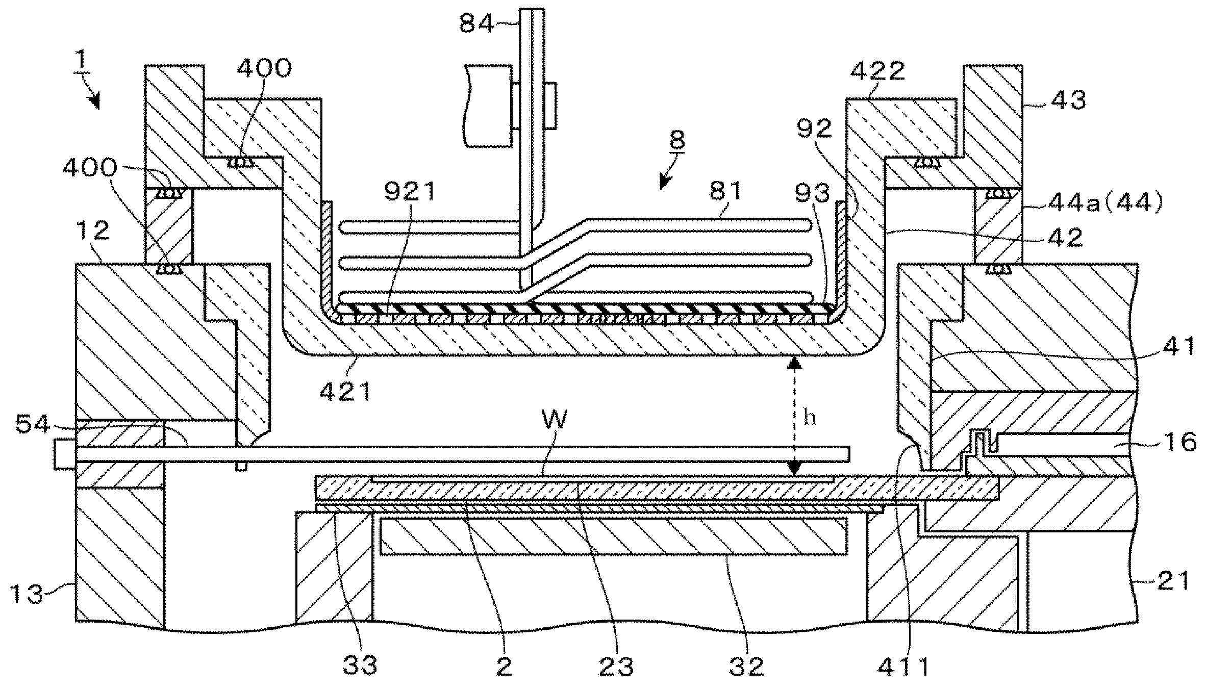
도 3은 상기 성막 장치의 확대 종단 측면도이다.
도 4는 상기 성막 장치에 설치되어 있는 플라스마 형성부 등의 분해 사시도이다.
도 5는 안테나 갭과 상기 성막 장치에서 성막된 막의 에칭 속도와의 관계를 도시하는 설명도이다.
도 6은 상기 성막 장치에 설치된 각 처리 영역 및 분리 영역을 나타내는 종단면 전개도이다.
도 7은 플라스마 창의 배치 높이의 변경에 관한 제1 설명도이다.
도 8은 상기 플라스마 창의 배치 높이의 변경에 관한 제2 설명도이다.
도 9는 상기 플라스마 창의 승강 기구를 구비한 성막 장치의 제1 확대 종단 측면도이다.
도 10은 상기 승강 기구를 구비한 성막 장치의 제2 확대 종단 측면도이다.1 is a longitudinal side view of a film forming apparatus according to an embodiment of the present invention.
2 is a cross-sectional plan view of the film forming apparatus.
3 is an enlarged longitudinal side view of the film forming apparatus.
4 is an exploded perspective view of a plasma forming portion and the like provided in the film forming apparatus.
5 is an explanatory diagram showing the relationship between the antenna gap and the etching rate of the film deposited in the film forming apparatus.
6 is a vertical sectional view showing each processing region and separation region provided in the film forming apparatus.
Fig. 7 is a first explanatory diagram concerning a change in the arrangement height of the plasma window. Fig.
Fig. 8 is a second explanatory diagram concerning a change in the arrangement height of the plasma window. Fig.
Fig. 9 is a first enlarged longitudinal sectional side view of the film forming apparatus provided with the plasma window lifting mechanism. Fig.
10 is a second enlarged longitudinal sectional side view of the film forming apparatus provided with the lifting mechanism.
본 발명의 일 실시 형태로서, ALD(Atomic Layer Deposition)법에 의해, 기판인 웨이퍼(W)에 대하여 SiO2막을 성막하는 성막 장치(1)에 대해서 설명한다. 본 예의 성막 장치(1)에서 실시되는 ALD법의 개요에 대해서 설명하면, Si(규소)를 포함하는 원료 가스(제1 처리 가스)인 예를 들어 BTBAS(비스터셔리부틸아미노실란)를 기화시킨 가스를 웨이퍼(W)에 흡착시킨 후, 당해 웨이퍼(W)의 표면에, 상기 BTBAS를 산화하는 산화 가스(제2 처리 가스)인 오존(O3) 가스를 공급해서 SiO2(이산화규소)의 분자층을 형성한다. 1매의 웨이퍼(W)에 대하여 이 일련의 처리를 복수회 반복해서 행함으로써, SiO2막이 형성된다.As an embodiment of the present invention, a
도 1, 2에 도시한 바와 같이, 성막 장치(1)는, 대략 원형의 편평한 금속제의 진공 용기(11)와, 진공 용기(11) 내에 설치된 원판 형상의 회전 테이블(2)을 구비하고 있다. 진공 용기(11)는, 천장부를 구성하는 천장판(12)과, 진공 용기(11)의 측벽 및 저부를 이루는 용기 본체(13)에 의해 구성되어 있다.1 and 2, the
회전 테이블(2)은, 예를 들어 석영 유리(이하, 간단히 「석영」이라고 함)에 의해 구성되고, 그 중심부에는 연직 하방으로 신장되는 금속제의 회전축(21)이 설치되어 있다. 회전축(21)은, 용기 본체(13)의 저부에 형성된 개구부(14) 및 하단부가 막힌 슬리브(141) 내에 삽입되고, 회전축(21)의 하단부에는, 회전 구동부(22)가 접속되어 있다. 또한, 웨이퍼(W)에 대한 금속에 의한 콘타미네이션의 우려가 작은 경우에는, 회전 테이블(2)은, 스테인레스 스틸 등의 금속에 의해 구성해도 된다.The rotary table 2 is made of, for example, quartz glass (hereinafter simply referred to as "quartz"), and a metal
회전 테이블(2)은, 회전축(21)을 통해서 진공 용기(11) 내에 수평으로 지지되고, 회전 구동부(22)의 작용에 의해, 상면측에서 보아 예를 들어 시계 방향으로 회전한다.The rotary table 2 is horizontally supported in the
또한, 슬리브(141)의 상단부에는, 회전 테이블(2)의 상면측으로부터 하면측으로의 원료 가스나 산화 가스 등의 진입을 방지하기 위해서, 슬리브(141)나 용기 본체(13)의 개구부(14)와, 회전축(21)과의 간극에 N2(질소) 가스를 공급하는 가스 공급관(15)이 설치되어 있다.The
한편, 진공 용기(11)를 구성하는 천장판(12)의 하면에는, 회전 테이블(2)의 중심부를 향해서 대향하도록 돌출되고, 평면 형상이 원환 형상인 중심부 영역(C)이 형성되어 있다. 또한 천장판(12)의 하면에는, 상기 중심부 영역(C)으로부터 회전 테이블(2)의 외측을 향해서 넓어지는, 평면 형상이 부채형인 돌출부(17)가, 회전 테이블(2)의 둘레 방향으로 서로 간격을 두고 2군데에 설치되어 있다. 바꿔 말하면, 이들 중심부 영역(C) 및 돌출부(17)는, 천장판(12)의 하면에, 그 외측 영역에 비해서 낮은 천장면을 형성하고 있다.On the lower surface of the
중심부 영역(C)의 내측과 회전 테이블(2)의 중심부와의 간극은 N2 가스의 유로(16)를 구성하고 있다. 이 유로(16)에는, 천장판(12)에 접속된 가스 공급관으로부터 N2 가스가 공급되고, 유로(16) 내에 유입한 N2가, 회전 테이블(2)의 상면과 중심부 영역(C)과의 간극으로부터, 그 전체 둘레에 걸쳐서 회전 테이블(2)의 직경 방향 외측을 향해서 토출된다. 이 N2 가스는, 회전 테이블(2) 상의 서로 다른 위치(후술하는 흡착 영역(제1 처리 영역)(R1) 및 산화 영역(제2 처리 영역)(R2))에 공급된 원료 가스나 산화 가스가, 회전 테이블(2)의 중심부(유로(16))를 바이패스로 해서 서로 접촉하는 것을 방지하고 있다.The gap between the inside of the central region C and the center of the rotary table 2 constitutes the N 2
도 1에 도시한 바와 같이 회전 테이블(2)의 하방에 위치하는 용기 본체(13)의 저면에는, 평면에서 보았을 때 원환 형상의 편평한 오목부(31)가, 상기 회전 테이블(2)의 둘레 방향을 따라 형성되어 있다. 이 오목부(31)의 저면에는, 회전 테이블(2)의 하면 전체에 대향하는 영역에 걸쳐서, 예를 들어 가늘고 긴 관상의 카본와이어 히터로 이루어지는 히터(32)가 배치되어 있다(도 1에는 히터(32)를 모식적으로 도시하고 있음). 히터(32)는, 도시하지 않은 급전부로부터의 급전에 의해 발열하여, 회전 테이블(2)을 통해서 웨이퍼(W)를 가열한다.As shown in Fig. 1, an annular flat
히터(32)가 배치된 오목부(31)의 상면은, 예를 들어 석영으로 이루어지는 원환 형상의 판 부재인 덮개(33)에 의해 막혀 있다.The upper surface of the
또한, 상기 오목부(31)의 외주측에 위치하는 용기 본체(13)의 저면에는, 진공 용기(11) 내를 배기하는 배기구(34, 35)가 개구되어 있다. 배기구(34, 35)의 하류측에는, 진공 펌프 등에 의해 구성된 도시하지 않은 진공 배기 기구가 접속되어 있다.
또한 도 2에 도시한 바와 같이, 용기 본체(13)의 측벽에는 웨이퍼(W)의 반입출구(36)과, 당해 반입출구(36)를 개폐하는 게이트 밸브(37)가 설치되어 있다. 외부의 반송 기구에 유지된 웨이퍼(W)는, 이 반입출구(36)를 통해서 진공 용기(11) 내에 반입된다. 회전 테이블(2)의 상면에는, 회전 테이블(2)의 회전 중심에 상당하는 유로(16)의 둘레를 둘러싸도록, 웨이퍼(W)의 적재 영역을 이루는 복수의 오목부(23)가 형성되어 있다. 진공 용기(11) 내에 반입된 웨이퍼(W)는, 각 오목부(23) 내에 적재된다. 반송 기구와 오목부(23)와의 사이의 웨이퍼(W)의 수수는, 각 오목부(23)에 설치된 도시하지 않은 관통구를 통해서 회전 테이블(2)의 상방 위치와 하방 위치와의 사이를 승강 가능하게 구성된 승강 핀을 통해서 행하여지지만, 승강 핀의 기재는 생략되어 있다.2, a loading /
또한 도 2에 도시한 바와 같이, 회전 테이블(2)의 상방에는, 원료 가스 노즐(51), 분리 가스 노즐(52), 산화 가스 노즐(53), 플라스마용 가스 노즐(54), 분리 가스 노즐(55)이 이 순서대로, 회전 테이블(2)의 회전 방향을 따라서 간격을 두고 배치되어 있다. 이들 가스 노즐(51 내지 55)은, 진공 용기(11)의 측벽으로부터, 회전 테이블(2)의 중심부를 향해서, 직경 방향을 따라서 수평으로 신장되는 막대 형상의 노즐 본체에 의해 구성되어 있다. 각 가스 노즐(51 내지 55)을 구성하는 노즐 본체의 하면에는, 다수의 토출구(56)가 서로 간격을 두고 형성되어 있다.2, a raw
원료 가스 노즐(51)은, 회전 테이블(2)의 상면측을 향해서, 도시하지 않은 원료 가스 공급원으로부터 공급된 이미 설명한 BTBAS 가스를 토출한다. 도 2, 6에 도시한 바와 같이, 원료 가스 노즐(51)은, 당해 원료 가스 노즐(51)로부터, 회전 테이블(2)의 회전 방향 상류측 및 하류측을 향해서 각각 넓어지는 부채형으로 형성된 노즐 커버(57)에 의해 덮여 있다. 노즐 커버(57)는, 그 하방에서의 BTBAS 가스의 농도를 높여서, 웨이퍼(W)로의 BTBAS 가스의 흡착성을 향상시키는 역할을 갖는다. 원료 가스 노즐(51)은, 본 예의 제1 처리 가스 공급부를 구성하고 있다.The raw
산화 가스 노즐(53)은, 도시하지 않은 산화 가스 공급원으로부터 공급된 오존 가스를 회전 테이블(2)의 상면측을 향해서 토출한다. 산화 가스 노즐(53)은, 본 예의 제2 처리 가스 공급부를 구성하고 있다.The oxidizing
또한 본 설명에서, 소정의 기준 위치로부터 회전 테이블(2)의 회전 방향을 따른 방향을 회전 방향의 하류측, 이것과 반대의 방향을 상류측이라고 한다.In this description, the direction along the rotational direction of the rotary table 2 from the predetermined reference position is referred to as the downstream side in the rotational direction, and the direction opposite thereto as the upstream side.
분리 가스 노즐(52, 55)은, 분리 가스인 불활성 가스, 예를 들어 N2 가스를 회전 테이블(2)의 상면측을 향해서 토출한다. 도 2, 6에 도시한 바와 같이, 각 분리 가스 노즐(52, 55)은, 천장판(12)에 형성된 부채형의 돌출부(17)를 둘레 방향으로 분할하는 위치에 형성된 홈부 내에 배치되어 있다.The
플라스마용 가스 노즐(54)은, 도시하지 않은 플라스마 발생용 가스 공급원으로부터 공급된 플라스마 발생용 가스, 예를 들어 아르곤(Ar) 가스와 산소(O2) 가스와의 혼합 가스를 회전 테이블(2)의 상면을 향해서 토출한다. 플라스마용 가스 노즐(54)은, 본 예의 플라스마 발생용 가스 공급부를 구성하고 있다.The
여기서 도 4에 도시한 바와 같이, 천장판(12)에는 회전 테이블(2)의 회전 방향을 따라서 넓어지는 부채형의 개구부가 설치되어 있다. 이 개구부에는, 후술하는 플라스마 형성부(8)를 수용하는 수용 용기(42)가 삽입되어 있다(도 1, 3). 수용 용기(42)는, 석영 등의 유전체로 이루어지고, 상기 개구부에 대응하는 평면 형상을 가짐과 함께, 종단측면 형상이 컵 모양으로 형성되어 있다. 본 예의 수용 용기(42)는, 회전 테이블(2)의 회전 방향에서 보아, 산화 가스 노즐(53)과 그 하류측의 돌출부(17)와의 사이의 하류측에 가까운 위치에 설치되어 있다. 플라스마용 가스 노즐(54)은, 수용 용기(42)의 하방측이며, 회전 테이블(2)의 회전 방향의 상류측에 위치하고, 반경 방향으로 신장되는 당해 수용 용기(42)의 변을 따라서 삽입되어 있다.As shown in Fig. 4, the
회전 테이블(2)의 상면측에 있어서, 원료 가스 노즐(51)의 노즐 커버(57)의 하방 영역은, 원료 가스인 BTBAS 가스의 흡착이 행하여지는 흡착 영역(R1)이며, 산화 가스 노즐(53)의 하방 영역은, 오존 가스에 의한 BTBAS 가스의 산화가 행하여지는 산화 영역(R2)이다.The area below the
본 실시 형태에서, 흡착 영역(R1)은 제1 처리 영역에 상당하고, 산화 영역(R2)은, 제2 처리 영역에 상당하고 있다.In the present embodiment, the adsorption region R1 corresponds to the first processing region and the oxidation region R2 corresponds to the second processing region.
또한, 이미 설명한 수용 용기(42)의 저면부(후술하는 플라스마 창(421)과 회전 테이블(2)과의 사이의 공간)는, 플라스마에 의한 SiO2막의 개질이 행하여지는 플라스마 형성 영역(R3)으로 되어 있다. 그리고, 돌출부(17)의 하방 영역은, 각 분리 가스 노즐(52, 55)로부터 토출되는 N2 가스에 의해, 흡착 영역(R1)과 산화 영역(R2)을 서로 분리하여, 원료 가스와 산화 가스와의 혼합을 방지하기 위한 분리 영역(D)을 각각 구성하고 있다.The space (the space between the
또한, 용기 본체(13)의 저면에 설치된 일방측의 배기구(34)는, 노즐 커버(57)(흡착 영역(R1))의 하류단 근방 위치이며, 회전 테이블(2)의 외측에 개구되어, 잉여의 BTBAS 가스를 배기한다. 타방측의 배기구(35)는, 플라스마 형성 영역(R3)과, 당해 플라스마 형성 영역(R3)에 대하여 상기 회전 방향의 하류측에 인접하는 분리 영역(D)과의 사이이며, 회전 테이블(2)의 외측에 개구되어, 잉여의 오존 가스나 플라스마 발생용 가스를 배기한다. 각 배기구(34, 35)로부터는, 각 분리 영역(D), 회전 테이블(2)의 하방의 가스 공급관(15), 회전 테이블(2)의 중심부 영역(C)으로부터 각각 공급되는 N2 가스도 배기된다.The one
이어서, 수용 용기(42) 내에 수용되는 플라스마 형성부(8) 등의 구성에 대해서 상세하게 설명한다.Next, the configuration of the
컵 모양으로 형성된 수용 용기(42)의 저면부를 플라스마 창(421)이라 칭하면, 도 3이나 분해 사시도인 도 4에 도시한 바와 같이, 이 플라스마 창(421)의 상면측에는, 상면측이 개구되는 상자형의 패러데이 실드(92)가 배치되어 있다. 패러데이 실드(92)는, 수용 용기(42)의 상면에 걸쳐진 프레임 형상체(91)를 통해서 수용 용기(42)에 지지되어 있다. 패러데이 실드(92)의 저면에는, 절연판(93)이 배치되고, 그 상면측에 플라스마 형성부(8)가 수용되어 있다.4, which is an exploded perspective view, the upper surface side of the
도 4에 도시한 바와 같이 패러데이 실드(92)의 저면은, 접지된 도전성의 판상체를 구성한다. 당해 판상체에는, 후술하는 안테나(81)로의 고주파 전력 인가 시에 당해 안테나(81)에 발생하는 전자계 중, 전계 성분이 하방을 향하는 것을 저지함과 함께, 자계 성분을 하방을 향하게 하기 위한 슬릿(921)이 형성되어 있다. 이 슬릿(921)은, 안테나(81)의 권회 방향에 대하여 직교(교차)하는 방향으로 신장되고, 안테나(81)의 권회 방향을 따라서 다수 형성되어 있다.As shown in Fig. 4, the bottom surface of the
도 4에 도시한 바와 같이, 예를 들어 플라스마 형성부(8)는, 금속선을 연직축 둘레에 코일 형상으로 권회해서 구성되는 안테나(81)를 구비하고, 평면에서 보았을 때 회전 테이블(2)의 중앙부측으로부터 외주부측에 걸쳐서 웨이퍼(W)의 통과 영역을 걸치도록 배치되어 있다. 안테나(81)의 일단은, 접속 전극(84) 및 정합기(매칭 박스)(82)를 통해서 고주파 전원(83)에 접속되어 있다(도 2). 고주파 전원(83)으로부터는, 예를 들어 주파수가 13.56MHz, 인가 전력이 5000W인 고주파 전력이 공급된다. 또한, 안테나(81)의 타단은, 또 하나의 접속 전극(84)을 통해서 접지되어 있다.As shown in Fig. 4, for example, the
상기 구성을 구비하는 플라스마 형성부(8)에 있어서, 안테나(81)에 고주파 전력을 인가하면, 플라스마 형성부(8)의 주위에 전자계가 발생하고, 패러데이 실드(92)를 통과한 자계 성분이 유전체제의 수용 용기(42)의 저면부를 투과하여, 수용 용기(42)의 하면측에 공급된 플라스마 발생용 가스를 플라스마화하는 유도 결합이 형성된다. 그래서 본 예에서는, 플라스마 발생용 자계를 투과시키는 수용 용기(42)의 저면부를 「플라스마 창(421)」이라고 칭하고 있다.When a high frequency electric power is applied to the
이때, 플라스마 발생용 가스의 플라스마는, 플라스마 창(421)의 근방 위치에서 발생하기 때문에, 회전 테이블(2)(회전 테이블(2) 상의 웨이퍼(W))에서 본 플라스마 창(421)의 배치 높이 위치는, 플라스마 처리의 특성을 변화시키는 조작 변수가 된다.Since the plasma of the plasma generating gas is generated in the vicinity of the
예를 들어 도 5는, 회전 테이블(2)과 플라스마 창(421)과의 사이의 거리(도 5 중에는 「안테나 갭」이라고 기재되어 있음)를 변화시켜서 SiO2막을 성막하고, 희불산(DHF)을 사용해서 성막 후의 SiO2막을 습식 에칭했을 때의 에칭 속도의 변화를 나타내고 있다.5 shows an example in which the SiO 2 film is formed by changing the distance between the
안테나 갭을 짧게 해 가면, 웨이퍼(W)의 표면에, 비교적 수명이 짧고, 반응성이 높은 이온을 보다 많이 공급할 수 있으므로, SiO2막은 치밀하고 단단해진다. 그 결과, SiO2막의 에칭 속도가 작아지는 경향을 확인할 수 있다(도 5의 횡축의 좌측에 대응하는 영역).If the antenna gap is shortened, the SiO 2 film becomes dense and hard because the life of the wafer W is short and the ion of high reactivity can be supplied to the surface of the wafer W more. As a result, it can be seen that the etching rate of the SiO 2 film tends to decrease (the region corresponding to the left side of the horizontal axis in FIG. 5).
또한, 웨이퍼(W)의 표면에 형성된 패턴 상에 성막을 행하는 경우, 수명이 짧은 이온은, 상부측의 영역에서 반응이 진행되기 쉽고, 하부측의 영역에서는 상방 영역과 비교해서 반응이 진행되기 어렵다는 경향도 나타난다. 그 결과, 패턴의 상부측이 치밀하고 단단하며, 하부측이 부드러운 특성 분포를 가진 막이 성막되는 경향이 있다.In addition, when the film is formed on the pattern formed on the surface of the wafer W, the reaction is likely to proceed in the region on the upper side and the reaction is less likely to proceed in the region on the lower side than in the region on the lower side Trends also appear. As a result, there is a tendency that a film whose upper side of the pattern is dense and hard and whose lower side has a soft characteristic distribution tends to be formed.
이에 반해 안테나 갭을 길게 해 가면, 웨이퍼(W)의 표면에 공급되는 활성종은, 이온과 비교해서 수명이 길고, 반응성이 낮은 라디칼이 주체가 된다. 그 결과, 플라스마 처리가 행하여진 막은, 이온이 많은 경우와 비교해서 치밀함은 낮아지고, 상대적으로 부드러워진다. 그 결과, SiO2막의 에칭 속도는 커지는 경향을 확인할 수 있다(도 5의 횡축의 우측에 대응하는 영역).On the other hand, if the antenna gap is made longer, the active species supplied to the surface of the wafer W will have a longer lifetime and lower reactivity than the ions. As a result, the film subjected to the plasma treatment has a lower denseness and relatively softness as compared with the case where the ion is present. As a result, the etching rate of the SiO 2 film tends to be large (region corresponding to the right side of the horizontal axis in FIG. 5).
또한 웨이퍼(W)의 표면에 형성된 패턴 상에 성막을 행하는 경우, 상대적으로 수명이 긴 라디칼은, 패턴 내에도 진입하기 쉬워, 이온이 많은 경우와 비교해서, 패턴의 상부측, 하부측에서 균질한 플라스마 처리가 행하여지는 경향도 있다.In addition, in the case of forming a film on a pattern formed on the surface of the wafer W, a radical having a relatively long lifetime easily enters the pattern, and compared with the case where ions are large, There is a tendency that the plasma treatment is performed.
이상에서 설명한 바와 같이 플라스마 형성부(8)는, 플라스마 창(421)의 배치 높이에 따라서 플라스마 처리의 결과를 조절하는 것이 가능하므로, 본 예의 성막 장치(1)는 천장판(12)의 개구부에 삽입된 수용 용기(42)를 승강시킴으로써, 플라스마 창(421)의 배치 높이 위치를 변경할 수 있다.As described above, the
이하, 도 3, 4 등을 참조하면서 플라스마 창(421)의 배치 높이 위치를 변경하는 기능에 대해서 설명한다.Hereinafter, the function of changing the arrangement height position of the
도 3, 4에 도시한 바와 같이, 컵 모양으로 형성된 본 예의 수용 용기(42)는, 컵 상면의 개구를 형성하는 테두리부의 둘레 방향을 따라, 외주측을 향해서 넓어지는 플랜지 형상의 피지지부(422)를 구비하고 있다. 이 피지지부(422)는, 수용 용기(42)보다도 한결 큰 환상의 부채형으로 형성되고, 상기 피지지부(422)와 끼워 맞추는 것이 가능한 절결을 구비한 금속제의 부재인 프레임체부(43)에 의해 하면측으로부터 지지된다.As shown in Figs. 3 and 4, the
또한 프레임체부(43)의 하면측에는, 당해 프레임체부(43)에 대응하는 환상의 부채형으로 형성된 금속제의 부재인 스페이서(44)를 배치할 수 있다. 본 예의 성막 장치(1)에서는, 서로 높이가 상이한 복수의 스페이서(44a, 44b)가 준비되어 있다.A
수용 용기(42)가 삽입되는 개구부의 주위의 천장판(12)의 상면에는, 프레임체부(43)가 직접 적재되거나(도 8), 또는 스페이서(44a, 44b)를 개재해서 프레임체부(43)가 적재된다(도 3, 7). 천장판(12)의 상면과 프레임체부(43)나 스페이서(44a, 44b)와의 사이, 스페이서(44a, 44b)와 프레임체부(43)와의 사이, 프레임체부(43)와 수용 용기(42)의 피지지부(422)와의 사이는 각각, 시일부인 O-링(400)에 의해 기밀하게 막힌다.The
프레임체부(43) 및 스페이서(44(44a, 44b))는, 본 예의 높이 조절부에 상당한다. 본 예의 높이 조절부는, 프레임체부(43)와 스페이서(44)로 상하로 분할되어 있다고 볼 수 있다. 이때, 프레임체부(43)는 상부측 환상 부재에 상당하고, 스페이서(44)는 하부측 환상 부재에 상당하고 있다.The
상술한 높이 조절부(프레임체부(43), 스페이서(44(44a, 44b)))를 개재해서 수용 용기(42)는, 천장판(12)(진공 용기(11))의 상면에 지지된 상태에서, 그 하부측 부분이 개구부 내에 삽입된다. 이 수용 용기(42)에서 보아, 당해 수용 용기(42)와 천장판(12)에 형성된 개구부의 내주면과의 사이에는, 당해 내주면의 전체를 내측으로부터 덮도록, 둘레 방향을 따라 환상으로 설치된 실드 부재(41)가 배치되어 있다. 실드 부재(41)는, 예를 들어 석영 등의 유전체에 의해 구성되고, 수용 용기(42)측의 플라스마 창(421)과, 금속제의 천장판(12)과의 사이에서 이상 방전이 형성되는 것을 방지하는 역할을 한다.The receiving
실드 부재(41)는, 천장판(12)의 개구부 내에 삽입됨과 함께, 천장판(12)의 개구부측에 형성된 절결 내에, 실드 부재(41)의 상단부에 설치된 플랜지부를 걸림 결합시킴으로써 천장판(12)으로부터 현수 지지되어 있다.The
예를 들어 도 6에 도시한 바와 같이, 실드 부재(41)의 하단부는, 천장판(12)의 하면보다도 하방측으로 돌출된 돌출부(411)로 되어 있다. 돌출부(411)와 회전 테이블(2)과의 사이에는, 회전 테이블(2)의 상면과 플라스마 창(421)과의 사이의 높이 치수(h)보다도 좁은, 높이 치수(h')의 간극이 형성되어 있다. 이미 설명한 플라스마용 가스 노즐(54)은, 상기 돌출부(411)(실드 부재(41))에 의해 둘러싸인 영역 내에 배치되어 있다.For example, as shown in Fig. 6, the lower end portion of the shielding
돌출부(411)는, 실드 부재(41)에 의해 둘러싸인 공간(플라스마 형성 영역(R3)에 대응하고 있음) 내에 공급된 플라스마 발생용 가스의 농도 저하를 억제함과 함께, 당해 공간의 외부에 공급된 N2 가스나 오존 가스의 진입을 억제하는 역할을 한다.The projecting
도 3에 도시한 바와 같이, 수용 용기(42)는, 상기 실드 부재(41)의 내측에 삽입된다. 여기서 수용 용기(42)의 외측면과 실드 부재(41)의 내측면과의 사이에는 간극이 형성되어 있지만, 천장판(12)과 수용 용기(42)의 피지지부(422)와의 사이에 설치된 프레임체부(43) 및 스페이서(44)의 각 부재의 사이가 O-링(400)에 의해 기밀하게 시일되어 있음으로써, 진공 용기(11) 내의 진공이 유지된다.As shown in Fig. 3, the receiving
이상에 설명한 구성을 구비하는 성막 장치(1)에는, 도 1에 도시한 바와 같이, 장치 전체의 동작의 컨트롤을 행하기 위한 컴퓨터로 이루어지는 제어부(7)가 설치되어 있다. 이 제어부(7)에는, 웨이퍼(W)로의 성막 처리를 실행하는 프로그램이 저장되어 있다. 상기 프로그램은, 성막 장치(1)의 각 부에 제어 신호를 송신해서 각 부의 동작을 제어한다. 구체적으로는, 각 가스 노즐(51 내지 55)로부터의 각종 가스의 공급량 조정, 히터(32)의 출력 제어, 가스 공급관(15) 및 중심부 영역(C)으로부터의 N2 가스의 공급량 조정, 회전 구동부(22)에 의한 회전 테이블(2)의 회전 속도 조정 등이, 제어 신호에 따라서 행하여진다. 상기 프로그램에서는 이들의 제어를 행하여, 상술한 각 동작이 실행되도록 스텝 군이 짜여져 있다. 당해 프로그램은, 하드 디스크, 콤팩트 디스크, 광자기 디스크, 메모리 카드, 플렉시블 디스크 등의 기억 매체로부터 제어부(7) 내에 인스톨된다.As shown in Fig. 1, the
이상으로 설명한 구성을 구비하는 성막 장치(1)의 동작에 대해서 설명한다.The operation of the
우선 성막 장치(1)는, 진공 용기(11) 내의 압력 및 히터(32)의 출력을 웨이퍼(W)의 반입 시의 상태로 조절하고, 웨이퍼(W)의 반입을 기다린다. 그리고, 예를 들어 인접하는 진공 반송실에 설치된 도시하지 않은 반송 기구에 의해 처리 대상의 웨이퍼(W)가 반송되어 오면, 게이트 밸브(37)를 개방한다. 반송 기구는, 개방된 반입출구(36)를 통해서 진공 용기(11) 내에 진입하여, 회전 테이블(2)의 오목부(23) 내에 웨이퍼(W)를 적재한다. 그리고, 각 오목부(23) 내에 웨이퍼(W)가 적재되도록, 회전 테이블(2)을 간헐적으로 회전시키면서 이 동작을 반복한다.The
웨이퍼(W)의 반입을 종료하면, 진공 용기(11) 내로부터 반송 기구를 퇴피시키고, 게이트 밸브(37)를 폐쇄한 후, 배기구(34, 35)로부터의 배기에 의해 진공 용기(11) 내를 소정의 압력까지 진공 배기한다. 또한, 분리 가스 노즐(52, 55)이나 중심부 영역(C)의 유로(16), 회전 테이블(2)의 하방측의 가스 공급관(15)으로부터는, 각각 소정량의 N2 가스가 공급되어 있다. 그리고, 회전 테이블(2)의 회전을 개시하여, 미리 설정된 회전 속도가 되도록 속도 조정을 행함과 함께, 급전부로부터 히터(32)로의 전력 공급을 개시해서 웨이퍼(W)를 가열한다.The transfer mechanism is retracted from the inside of the
그리고, 웨이퍼(W)가 설정 온도인 예를 들어 400℃까지 가열되면, 원료 가스 노즐(51), 산화 가스 노즐(53), 플라스마용 가스 노즐(54)로부터의 각종 가스(원료 가스, 산화 가스, 플라스마 발생용 가스)의 공급을 개시함과 함께, 플라스마 형성부(8)에 고주파 전력을 인가한다.When the wafer W is heated to a set temperature of, for example, 400 DEG C, various gases (raw material gas, oxidizing gas, etc.) are supplied from the raw
원료 가스, 산화 가스의 공급에 의해, 회전 테이블(2)의 각 오목부(23)에 적재된 웨이퍼(W)는, 원료 가스 노즐(51)의 노즐 커버(57)의 하방의 흡착 영역(R1), 산화 가스 노즐(53)의 하방의 산화 영역(R2), 수용 용기(42)(플라스마 형성부(8))의 하방측의 플라스마 형성 영역(R3)을, 이 순서로 반복해서 통과한다(도 6).The wafers W placed on the
그리고, 흡착 영역(R1)에서는 원료 가스 노즐(51)로부터 토출된 BTBAS 가스가 웨이퍼(W)에 흡착되고, 산화 영역(R2)에서는 흡착된 BTBAS가, 산화 가스 노즐(53)로부터 공급된 오존 가스에 의해 산화되어, SiO2의 분자층이 1층 또는 복수층 형성된다. 또한, 플라스마 형성 영역(R3)에서는, 웨이퍼(W)에 성막된 SiO2의 분자층이 플라스마로부터 공급된 활성종과 접촉해서 당해 분자층을 개질하는 처리가 행하여진다.The BTBAS gas discharged from the raw
이렇게 해서 회전 테이블(2)의 회전을 계속하면, 웨이퍼(W)의 표면에 SiO2의 분자층이 순차 적층되어, SiO2막이 형성됨과 함께 그 막 두께가 점차 커진다.When the rotation of the rotary table 2 is continued in this manner, the molecular layers of SiO 2 are sequentially laminated on the surface of the wafer W to form the SiO 2 film, and the film thickness gradually increases.
또한, 이때, 흡착 영역(R1)과 산화 영역(R2)과의 사이, 플라스마 형성 영역(R3)과 흡착 영역(R1)과의 사이는, 분리 영역(D)에 의해 분리되어 있으므로, 불필요한 장소에서는 원료 가스와 산화 가스와의 접촉에 기인하는 퇴적물은 발생하기 어렵다.At this time, since the separation between the adsorption region R1 and the oxidation region R2 and between the plasma formation region R3 and the adsorption region R1 are separated by the separation region D, So that sediments caused by contact between the raw material gas and the oxidizing gas are less likely to occur.
상술한 동작을 실행하여, 각 웨이퍼(W)에 원하는 막 두께의 SiO2막이 형성되는 타이밍, 예를 들어 소정 횟수만큼 회전 테이블(2)을 회전시킨 타이밍에서, 원료 가스 노즐(51), 산화 가스 노즐(53), 플라스마용 가스 노즐(54)로부터의 각종 가스의 공급, 플라스마 형성부(8)로의 고주파 전력의 인가를 정지한다. 그리고, 회전 테이블(2)의 회전을 정지함과 함께, 히터(32)의 출력을 대기 시의 상태로 하고, 성막 처리를 종료한다.The above operation is carried out so that the raw
그런 뒤, 진공 용기(11) 내의 압력을 웨이퍼(W)의 반출 시의 상태로 조절하고, 게이트 밸브(37)를 개방하여, 반입 시와는 반대의 수순으로 웨이퍼(W)를 취출하고, 성막 처리를 종료한다.Thereafter, the pressure in the
상술한 동작에 의해 성막이 행하여지는 성막 장치(1)에서는, 플라스마 형성 영역(R3)에서 플라스마 처리를 행할 때, SiO2막에 요구되는 특성이 상이한 경우가 있다. 예를 들어 도 5를 사용해서 설명한 바와 같이, 보다 치밀하고 단단한 SiO2막을 형성하고 싶은 경우에는, 이온에 의한 개질의 영향을 크게 하고, 웨이퍼(W)에 형성된 패턴의 상부측, 하부측의 사이에서 보다 균질한 개질을 행하고 싶은 경우에는, 라디칼에 의한 개질의 영향을 크게 하는 것이 바람직하다.In the
이때, 예를 들어 고주파 전원(83)으로부터 인가되는 고주파 전력을 증감시켜, 플라스마 발생용 가스의 전리 상태를 변화시킴으로써도 이온에 의한 개질의 영향이 큰 상태나, 라디칼에 의한 개질의 영향이 큰 상태를 조절할 수 있다.At this time, for example, by changing the ionization state of the plasma generating gas by increasing or decreasing the high-frequency power applied from the high-
그러나, 이 경우에는, 고주파 전력의 증감에 따라, 플라스마의 크기도 변화해버리는 경우가 있으므로, 고주파 전력의 증감 전후에, 플라스마 처리의 면내 균일성 등이 변화해버릴 우려도 있다.However, in this case, there is a possibility that the plasma in-plane uniformity or the like of the plasma processing may change before and after the increase / decrease of the high-frequency power because the size of the plasma may change with the increase or decrease of the high-frequency power.
그래서 본 예의 성막 장치(1)는, 이미 설명한 바와 같이 프레임체부(43)나 스페이서(44a, 44b)로 이루어지는 높이 조절부를 사용해서 플라스마 창(421)의 배치 높이 위치를 변화시킴으로써, 웨이퍼(W)에 대하여 실시되는 플라스마 처리의 특성을 변화시킨다.Thus, the
도 3에 도시하는 예는, 회전 테이블(2)의 상면과 플라스마 창(421)과의 사이의 거리(안테나 갭)가 h=45mm이며, 성막 장치(1)를 사용해서 성막된 SiO2막의 DHF에 의한 에칭 속도가, 약 14Å/분이었던 것으로 한다. 이때, SiO2막의 막질을 보다 치밀하게 하고 싶은 경우에는, 성막 장치(1)를 정지하고, 진공 용기(11)의 진공 상태를 해제한 후, 지그 등으로 프레임체부(43)와 수용 용기(42)를 들어올려, 도 3의 스페이서(44a)보다도 높이 치수가 큰 스페이서(44b)로의 교환을 행한다.3 shows a case where the distance (antenna gap) between the upper surface of the
그런 뒤, 스페이서(44b) 상에 프레임체부(43), 수용 용기(42)를 적재하고, 도 7에 도시하는 바와 같이 안테나 갭을 hH=90mm으로 변경했다고 하면, 도 5에 의하면, 플라스마 처리에서의 라디칼의 영향이 커져, 당해 조건에서 성막된 SiO2막의 에칭 속도를 약 71Å/분까지 증대시킬 수 있다.7, when the antenna gap is changed to h H = 90 mm as shown in Fig. 7, according to Fig. 5, the plasma processing is performed The etching rate of the SiO 2 film formed under the above conditions can be increased to about 71 ANGSTROM / min.
한편, 도 8에 도시한 바와 같이, 스페이서(44a, 44b)의 배치를 생략하고, 천장판(12)의 상면에 직접, 프레임체부(43)를 적재해서 안테나 갭을 hL=30mm로 변경했다고 하면, 플라스마 처리에서의 이온의 영향이 커져, 도 5에 의하면, 당해 조건에서 성막된 SiO2막의 에칭 속도는 약 9Å/분까지 저하된다.8, if the arrangement of the
이렇게 플라스마 창(421)의 배치 높이 위치를 승강시켜서 플라스마 처리의 특성을 변화시키는 본 예의 성막 장치(1)에서는, 안테나(81)에 인가하는 고주파 전력을 일정하게 유지할 수 있으므로, 고주파 전력의 증감에 수반하는 플라스마 상태의 변화가 발생하기 어렵다.Thus, in the
또한, 플라스마 창(421)의 배치 높이 위치를 변화시키는 방법으로서는, 예를 들어 컵의 깊이가 상이한 복수 종류의 수용 용기(42)를 준비해 두고, 플라스마 창(421)의 배치 높이 위치에 따라서 수용 용기(42) 전체를 교환하는 방법도 상정할 수 있다. 그러나, 석영제의 수용 용기(42)는 고가이므로, 복수의 수용 용기(42)를 준비하는 것은 성막 장치(1)의 장치 비용의 증대 요인으로 되어버린다. 이 점에서, 본 예의 성막 장치(1)는, 금속제의 환상의 부재인 스페이서(44a, 44b)의 교환, 철거, 재배치를 행하는 것만으로, 플라스마 창(421)의 배치 높이 위치를 변화시키는 것이 가능하다. 그 결과, 장치 비용을 크게 저감할 수 있을 뿐만 아니라, 플라스마 창(421)의 배치 높이 위치의 변경 작업에 대해서도 대폭 간소화할 수 있다.As a method for changing the arrangement height position of the
나아가, 피지지부(422)를 지지하는 프레임체부(43)와, 스페이서(44a, 44b)를 상하로 분할함으로써, 형상이 보다 간소한 스페이서(44)에 대해서만, 서로 높이가 상이한 복수의 스페이서(44a, 44b)를 준비하면 되므로, 높이 조절부의 부재 비용을 더욱 저감할 수 있다.Further, by dividing the
단, 당해 예는, 프레임체부(43)와 스페이서(44a, 44b)가 일체화된 환상 부재에 의해 높이 조절부를 구성하고, 당해 환상 부재를 교환함으로써, 플라스마 창(421)의 배치 높이 위치를 변경하는 방법의 채용을 부정하는 것은 아니다.However, in this example, the height adjustment portion is constituted by the annular member in which the
또한, 본 예의 성막 장치(1)는, 수용 용기(42)와 실드 부재(41)가 서로 분리되고, 실드 부재(41)는 천장판(12)의 개구부의 내주면을 덮은 상태로 고정되어 있다.In the
예를 들어 수용 용기(42)와 실드 부재(41)가 일체로 구성되어 있는 경우에는, 플라스마 갭이 커지도록 수용 용기(42)를 배치하면, 금속제의 천장판(12)의 내주면이 노출되어, 플라스마 창(421)과 당해 내주면과의 사이에 이상 방전이 형성되어버릴 우려가 있다.For example, when the receiving
이 점에서, 실드 부재(41)가 소정의 높이 위치에 고정 배치된 본 예의 성막 장치(1)에서는, 수용 용기(42)의 배치 높이 위치에 관계없이, 천장판(12)의 내주면이 노출되지 않으므로, 이상 방전의 발생을 억제하고, 안정적으로 플라스마를 형성할 수 있다.In this regard, in the
또한, 수용 용기(42)와 실드 부재(41)를 일체로 구성한 경우에 있어서, 플라스마 갭이 커지는 위치에 수용 용기(42)를 배치하면, 도 6에 나타내는 돌출부(411)와 회전 테이블(2)과의 간극의 높이 치수(h')가 커진다. 그 결과, 플라스마 발생용 가스의 농도 저하의 억제 작용이나 외부에 공급된 N2 가스, 오존 가스의 진입 억제 작용이 얻어지기 어렵게 되어버릴 우려도 있다.6 and the rotary table 2 can be obtained by arranging the
이 점에 대해서도, 돌출부(411)가 소정의 높이 위치에 고정 배치된 본 예의 성막 장치(1)에서는, 수용 용기(42)의 배치 높이 위치에 관계없이, 돌출부(411)와 회전 테이블(2)과의 간극의 높이 치수(h')는 일정하므로, 상시, 양호한 플라스마 발생용 가스의 농도 저하의 억제 작용, 외부에 공급된 가스의 진입 억제 작용을 얻을 수 있다.In this regard, in the
본 실시 형태에 관한 성막 장치(1)에 의하면 이하의 효과가 있다. 미리 설정된 높이 위치에 실드 부재(41)가 배치되어 있으므로, 높이 조절부(프레임체부(43), 스페이서(44a, 44b))를 사용한 수용 용기(42)의 배치 높이 위치의 변화에 관계없이, 금속제의 천장판(12)(진공 용기(11))에 설치한 개구부의 내주면이 실드 부재(41)에 덮인 상태가 유지되어, 안정된 플라스마를 형성할 수 있다.The
계속해서, 도 9, 10을 참조하면서, 다른 방법에 의해 수용 용기(42)의 배치 높이 위치를 변경하는 높이 조절부를 구비한 성막 장치(1a)의 구성예에 대해서 설명한다. 도 9, 10에 나타내는 성막 장치(1a)에 있어서, 도 1 내지 4 등을 사용해서 설명한 것과 공통의 구성 요소에는, 이들 도에서 사용한 것과 공통의 부호를 붙이고 있다.Next, a configuration example of the
도 9, 10에 나타내는 성막 장치(1a)는, 상단부에 형성된 플랜지 형상의 피지지부(422)를 프레임체부(43)에 의해 지지하고, 이 프레임체부(43)와 천장판(12)(진공 용기(11))의 상면과의 사이에 벨로우즈(46)를 설치하고 있다. 바꿔 말하면, 피지지부(422)와 천장판(12)과의 사이의 간극이 프레임체부(43) 및 벨로우즈(46)에 의해 막혀 있다고 할 수 있다.The
또한, 본 예의 프레임체부(43)의 측 둘레면에는, 프레임체부(43)의 둘레 방향을 향해서 서로 간격을 두고, 복수의 승강 기구(45)가 배치되어 있다. 각 승강 기구(45)는, 신축 가능한 신축부(452)와, 당해 신축부(452)를 구동하는 구동부(451)를 구비한다. 본 예의 승강 기구(45)는, 신축부(452)의 하단은 천장판(12)의 상면에 고정되는 한편, 구동부(451)는 지지부(453)에 의해 프레임체부(43)의 측 둘레면에 고정되어 있다.A plurality of lifting
이들 승강 기구(45)에 있어서, 신축부(452)를 신장시키면, 수용 용기(42)의 배치 높이 위치가 상방측으로 이동하여, 플라스마 창(421)과 회전 테이블(2)과의 사이의 플라스마 갭을 hH까지 크게 할 수 있다(도 9). 이때, 수용 용기(42)의 이동에 맞춰서 벨로우즈(46)가 신장된다.In this elevating
또한, 신축부(452)를 축퇴시키면, 수용 용기(42)의 배치 높이 위치가 하방측으로 이동하여, 상기 플라스마 갭을 hL까지 작게 할 수 있다(도 10). 이때, 수용 용기(42)의 이동에 맞춰서 벨로우즈(46)가 줄어든다.Further, when the stretchable and
또한, 본 예에서는, 승강 기구(45)의 설치의 용이성 관점에서, 금속제의 프레임체부(43)와 천장판(12)과의 사이에 벨로우즈(46)를 설치한 예를 나타냈다. 단, 석영제의 실드 부재(41)에 벨로우즈(46)나 승강 기구(45)를 설치하는 것이 가능한 경우에는, 프레임체부(43)의 설치를 생략하고, 수용 용기(42)와 실드 부재(41)와의 사이를 벨로우즈(46)로 막고, 수용 용기(42)에 설치한 승강 기구(45)에 의해 수용 용기(42)를 승강시키는 구성을 채용해도 된다.In the present embodiment, an example in which the
또한, 상술한 각 실시 형태에서는, 플라스마 형성 영역(R3)에서 실시되는 플라스마 처리가, 웨이퍼(W)의 표면에 형성된 SiO2막(SiO2의 분자층)을 개질하기 위한 개질 처리인 경우에 대해서 설명하였다.In each of the above-described embodiments, the case where the plasma treatment performed in the plasma forming region R3 is a modification treatment for modifying the SiO 2 film (SiO 2 molecular layer) formed on the surface of the wafer W .
단, 플라스마 형성 영역(R3)에서 실시되는 플라스마 처리의 내용은 상술한 예에 한정되는 것은 아니다. 예를 들어 도 2에 도시하는 산화 영역(R2)으로의 산화 가스 노즐(53)의 배치를 생략하는 한편, 현재, 플라스마용 가스 노즐(54)이 배치되어 있는 위치에 오존 가스 공급용 산화 가스 노즐(53)을 배치하여, 오존 가스(산화 가스)를 플라스마화해서 웨이퍼(W)에 흡착된 BTBAS와의 반응을 진행시켜도 된다.However, the content of the plasma treatment performed in the plasma forming region R3 is not limited to the above example. For example, the arrangement of the oxidizing
상술한 예는 플라스마 처리가 성막 처리의 일부를 구성하고, 제2 처리 가스인 오존 가스는 플라스마 발생용 가스의 기능을 겸비하고, 제2 처리 가스 공급부인 산화 가스 노즐(53)은 플라스마 발생용 가스 공급부에도 상당하고 있다고 할 수 있다.In the above-described example, the plasma process constitutes a part of the film forming process, the ozone gas as the second process gas has the function of the plasma generating gas, and the oxidizing
또한, 플라스마 형성부(8)의 구성은, 플라스마 발생용 가스와의 유도 결합에 의해 플라스마를 형성하는 안테나(81)를 사용하는 경우에 한정되지 않는다. 예를 들어 마이크로파 발생기에서 발생시킨 마이크로파를, 도파관을 통해서 수용 용기(42)의 저면부에 설치된 유전체 플레이트에 전파시켜, 유전체 플레이트로부터 플라스마 발생용 가스를 향해서 마이크로파를 공급해서 플라스마를 발생시키는 마이크로파 방식의 플라스마 형성부를 설치해도 된다.The configuration of the
그 밖에, 금속에 의한 콘타미네이션을 방지하기 위해서, 금속이 노출되어 있는 공간 내에서 웨이퍼(W)의 처리를 행하는 것이 바람직하지 않은 경우에는, 예를 들어 진공 용기(11)의 내측에 석영제의 용기를 설치하고, 이 석영 용기 내에 회전 테이블(2)을 배치해도 된다. 이 경우에는, 석영 용기의 상면측에, 플라스마 형성부(8)의 수용 용기(42)나, 실드 부재(41)를 삽입하는 개구부가 설치된다.In addition, when it is not preferable to perform the processing of the wafer W in the space in which the metal is exposed in order to prevent contaminants caused by the metal, for example, a quartz And a rotary table 2 may be disposed in the quartz container. In this case, an opening for inserting the receiving
그 밖에, 본 예의 성막 장치(1)를 사용해서 성막되는 SiO2막의 원료나, 성막되는 막의 종류는, 상술한 예에 한정되는 것은 아니다. 예를 들어 디클로로실란(DCS) 가스를 원료 가스(제1 처리 가스)로 하고, 오존 가스 또는 플라스마화된 오존 가스를 산화 가스(제2 처리 가스, 플라스마 발생용 가스)로 해서 SiO2막을 성막해도 된다. 또한, DCS 가스나 BTBAS 가스를 원료 가스로 하고, 산화 가스 대신에 암모니아(NH3) 가스나 일산화이질소(N2O) 가스, 이들 가스의 플라스마 등의 질화 가스(제2 처리 가스, 플라스마 발생용 가스)를 사용해서 SiN막을 성막하는 예 등, 다양한 성막 처리에 대해서, 본 예의 성막 장치(1, 1a)를 적용할 수 있다.In addition, the raw material of the SiO 2 film to be formed using the
W : 웨이퍼
1, 1a : 성막 장치
11 : 진공 용기
14 : 개구부
2 : 회전 테이블
21 : 회전축
23 : 오목부
34, 35 : 배기구
400 : O-링
41 : 실드 부재
411 : 돌출부
42 : 수용 용기
421 : 플라스마 창
422 : 피지지부
43 : 프레임체부
44, 44a, 44b : 스페이서
45 : 승강 기구
46 : 벨로우즈
8 : 플라스마 형성부
92 : 패러데이 실드W:
11: Vacuum container 14:
2: rotating table 21: rotating shaft
23:
400: O-ring 41: shield member
411: protrusion 42: receptacle container
421: Plasma window 422:
43:
45: lifting mechanism 46: bellows
8: Plasma forming part 92: Faraday shield
Claims (8)
분리 영역을 개재해서 상기 회전 테이블의 둘레 방향으로 서로 이격된 제1 처리 영역, 제2 처리 영역에, 각각 제1 처리 가스, 제2 처리 가스를 공급하기 위한 제1 처리 가스 공급부 및 제2 처리 가스 공급부와,
기판에 대하여 플라스마 처리를 행하기 위해서, 상기 진공 용기 내에 플라스마 발생용 가스를 공급하는 플라스마 발생용 가스 공급부와,
상기 플라스마 발생용 가스를 플라스마화하기 위한 플라스마 형성부와,
상기 진공 용기의 천장부측에 형성된 개구부에 삽입되고, 상기 회전 테이블의 상면과 대향하는 저면부를 포함함과 함께, 상기 저면부의 상면측에 상기 플라스마 형성부를 수용한 수용 용기와,
상기 수용 용기와 상기 진공 용기의 개구부의 내주면과의 사이에 배치되고, 당해 내주면의 둘레 방향을 따라 환상으로 설치된 유전체제의 실드 부재와,
상기 진공 용기 내에 삽입된 상기 수용 용기의 저면부의 배치 높이 위치를 조절하기 위한 높이 조절부와,
상기 진공 용기와 상기 개구부에 삽입된 수용 용기와의 사이를 기밀하게 막기 위한 하나 이상의 시일부를 포함하는 성막 장치.The substrate is loaded in the substrate mounting region on the upper surface side of the rotary table provided in the metal vacuum container and the rotary table is rotated so that the substrate is revolved around the rotation center of the rotary table, And a second process gas are sequentially supplied to perform a film forming process,
A first process gas supply part for supplying a first process gas and a second process gas to the first process area and the second process area which are separated from each other in the circumferential direction of the rotary table via the separation area, A supply section,
A plasma generating gas supply unit for supplying a plasma generating gas into the vacuum chamber so as to perform a plasma process on the substrate,
A plasma forming unit for plasma-forming the plasma generating gas,
A bottom surface portion of the bottom surface portion facing the top surface of the rotary table and being inserted into an opening portion formed in a ceiling portion side of the vacuum container, the accommodating container accommodating the plasma forming portion on an upper surface side of the bottom surface portion,
A shielding member of a dielectric type provided between the accommodating container and the inner circumferential surface of the opening of the vacuum container and provided annularly along the circumferential direction of the inner circumferential surface,
A height adjuster for adjusting an arrangement height position of a bottom portion of the accommodating container inserted in the vacuum container,
And at least one seal portion for airtightly sealing between the vacuum container and a container accommodated in the opening.
상기 실드 부재는, 상기 진공 용기의 천장부측으로부터 회전 테이블측을 향해서 돌출되는 돌출부를 포함하고,
상기 돌출부와 회전 테이블과의 사이에는, 상기 회전 테이블의 상면과 상기 수용 용기의 저면부와의 사이의 거리보다도 좁은 간극이 형성되는 성막 장치.The method according to claim 1,
Wherein the shield member includes a protruding portion protruding from the ceiling portion side of the vacuum container toward the rotary table side,
Wherein a clearance narrower than a distance between an upper surface of the rotary table and a bottom surface portion of the accommodating container is formed between the protruding portion and the rotary table.
상기 수용 용기는, 상기 개구부로부터 진공 용기의 외부에 돌출된 수용 용기의 둘레 방향을 따라 형성된 플랜지 형상의 피지지부를 포함하고,
상기 높이 조절부는, 상기 개구부의 주위의 진공 용기의 상면과, 상기 수용 용기의 피지지부와의 사이에 배치되고, 당해 피지지부를 통해서 수용 용기를 진공 용기 상에 지지하는 환상 부재에 의해 구성되고, 서로 높이가 상이한 복수의 환상 부재를 교환함으로써 상기 저면부의 배치 높이 위치의 조절이 행하여지고,
상기 시일부는, 상기 진공 용기와 높이 조절부와의 사이, 및 높이 조절부와 피지지부와의 사이에 설치되는 성막 장치.3. The method according to claim 1 or 2,
The accommodating container includes a flange-shaped supported portion formed along the circumferential direction of the accommodating container protruding from the opening portion to the outside of the vacuum container,
The height adjusting portion is constituted by an annular member which is disposed between the upper surface of the vacuum container around the opening and the supported portion of the accommodating container and which supports the accommodating container on the vacuum container through the supported portion, The arrangement height position of the bottom portion is adjusted by exchanging a plurality of annular members having different heights,
Wherein the sealing portion is provided between the vacuum container and the height adjusting portion, and between the height adjusting portion and the supported portion.
상기 환상 부재는, 상기 피지지부를 지지하는 상부측 환상 부재와, 이 상부측 환상 부재와 진공 용기의 상면과의 사이에 배치되는 하부측 환상 부재로 상하로 분할되고,
상기 복수의 환상 부재의 교환은, 상기 하부측 환상 부재의 배치를 생략하고 상기 상부측 환상 부재를 진공 용기의 상면에 직접 배치하거나, 또는 서로 높이가 상이한 복수의 하부측 환상 부재를 교환해서 배치함으로써 행하여지고,
상기 진공 용기의 상면과 피지지부와의 사이에 하부측 환상 부재 및 상부측 환상 부재가 배치되어 있는 경우에, 상기 시일부는, 이들 하부측 환상 부재와 상부측 환상 부재와의 사이에도 설치되는 성막 장치.The method of claim 3,
Wherein the annular member is divided into upper and lower annular members which are arranged between the upper annular member and the upper surface of the vacuum container and which support the supported portion,
The replacement of the plurality of annular members may be performed by arranging the upper annular member directly on the upper surface of the vacuum container without arranging the lower annular member or arranging a plurality of lower annular members different in height from each other in an interchangeable manner However,
Wherein when the lower annular member and the upper annular member are disposed between the upper surface and the supported portion of the vacuum container, the seal portion is provided between the lower annular member and the upper annular member, .
상기 높이 조절부는, 상기 수용 용기를 지지해서 상하 방향으로 이동시키는 승강 기구를 포함하고,
상기 시일부는, 상기 진공 용기와 상기 개구부에 삽입된 수용 용기와의 사이를 기밀하게 막고, 당해 수용 용기의 상하 이동에 따라 신축 가능한 벨로우즈를 포함하는 성막 장치.3. The method according to claim 1 or 2,
Wherein the height adjusting portion includes an elevating mechanism for supporting the accommodating container and moving the accommodating container in a vertical direction,
Wherein the sealing portion includes a bellows that hermetically closes between the vacuum container and a container inserted in the opening and that is expandable and contractible in accordance with the vertical movement of the container.
상기 플라스마 형성부는, 상기 플라스마 발생용 가스를 유도 결합에 의해 플라스마화하기 위해서, 상기 회전 테이블의 상면측에 대향해서 설치된 안테나와, 상기 안테나의 주위에 발생한 전자계에서의 전계 성분의 통과를 저지함과 함께 자계 성분을 상기 플라스마 발생용 가스측에 통과시키기 위해서, 각각 안테나와 직교하는 방향으로 신장되는 슬릿이 안테나의 연신 방향을 따라서 다수 배열되고, 또한 접지된 도전성의 판상체로 이루어지는 패러데이 실드를 포함하고,
상기 수용 용기는 유전체에 의해 구성되는 성막 장치.3. The method according to claim 1 or 2,
Wherein the plasma generating unit comprises an antenna provided to face the upper surface side of the rotary table so as to plasmaize the plasma generating gas by inductive coupling and a plasma generator for preventing passage of an electric field component in an electromagnetic field generated around the antenna, A plurality of slits elongated in a direction perpendicular to the antenna are arranged along the extending direction of the antenna so as to allow the magnetic field component to pass to the side of the plasma generating gas and a Faraday shield composed of a grounded conductive plate ,
Wherein said accommodating container is constituted by a dielectric.
상기 플라스마 처리는 성막 처리의 일부를 구성하고, 상기 플라스마 발생용 가스는, 상기 제2 처리 가스이며, 상기 플라스마 발생용 가스 공급부는, 상기 제2 처리 가스 공급부인 성막 장치.3. The method according to claim 1 or 2,
Wherein the plasma processing part is a part of a film forming process, the plasma generating gas is the second process gas, and the plasma generating gas supplying part is the second process gas supplying part.
상기 플라스마 발생용 가스 공급부는, 상기 회전 테이블의 회전 방향의 하류측의 영역에 상기 플라스마 발생용 가스를 공급하고, 상기 플라스마 처리는, 상기 제1 처리 가스와 제2 처리 가스와의 반응에 의해 기판 상에 형성된 막을 개질하는 처리인 성막 장치.3. The method according to claim 1 or 2,
Wherein the plasma generating gas supply unit supplies the plasma generating gas to a region on the downstream side of the rotating direction of the rotary table and the plasma processing is performed by a reaction between the first process gas and the second process gas, Is a process of modifying a film formed on a substrate.
Applications Claiming Priority (2)
| Application Number | Priority Date | Filing Date | Title |
|---|---|---|---|
| JP2017033518A JP6750534B2 (en) | 2017-02-24 | 2017-02-24 | Film deposition equipment |
| JPJP-P-2017-033518 | 2017-02-24 |
Publications (2)
| Publication Number | Publication Date |
|---|---|
| KR20180098136A true KR20180098136A (en) | 2018-09-03 |
| KR102313812B1 KR102313812B1 (en) | 2021-10-18 |
Family
ID=63246069
Family Applications (1)
| Application Number | Title | Priority Date | Filing Date |
|---|---|---|---|
| KR1020180017330A Active KR102313812B1 (en) | 2017-02-24 | 2018-02-13 | Film forming apparatus |
Country Status (3)
| Country | Link |
|---|---|
| US (1) | US11155918B2 (en) |
| JP (1) | JP6750534B2 (en) |
| KR (1) | KR102313812B1 (en) |
Families Citing this family (13)
| Publication number | Priority date | Publication date | Assignee | Title |
|---|---|---|---|---|
| JP7145648B2 (en) * | 2018-05-22 | 2022-10-03 | 東京エレクトロン株式会社 | Substrate processing method and substrate processing apparatus |
| US10998209B2 (en) | 2019-05-31 | 2021-05-04 | Applied Materials, Inc. | Substrate processing platforms including multiple processing chambers |
| JP2021180215A (en) | 2020-05-11 | 2021-11-18 | 東京エレクトロン株式会社 | Plasma processing method, plasma processing device and control device |
| US12660553B2 (en) | 2020-06-01 | 2026-06-16 | Applied Materials, Inc. | High temperature and vacuum isolation processing mini-environments |
| US12080571B2 (en) | 2020-07-08 | 2024-09-03 | Applied Materials, Inc. | Substrate processing module and method of moving a workpiece |
| US11817331B2 (en) | 2020-07-27 | 2023-11-14 | Applied Materials, Inc. | Substrate holder replacement with protective disk during pasting process |
| US11749542B2 (en) | 2020-07-27 | 2023-09-05 | Applied Materials, Inc. | Apparatus, system, and method for non-contact temperature monitoring of substrate supports |
| US11600507B2 (en) | 2020-09-09 | 2023-03-07 | Applied Materials, Inc. | Pedestal assembly for a substrate processing chamber |
| US11610799B2 (en) | 2020-09-18 | 2023-03-21 | Applied Materials, Inc. | Electrostatic chuck having a heating and chucking capabilities |
| JP7500450B2 (en) * | 2021-01-21 | 2024-06-17 | 東京エレクトロン株式会社 | Plasma Processing Equipment |
| US12195314B2 (en) | 2021-02-02 | 2025-01-14 | Applied Materials, Inc. | Cathode exchange mechanism to improve preventative maintenance time for cluster system |
| US11674227B2 (en) | 2021-02-03 | 2023-06-13 | Applied Materials, Inc. | Symmetric pump down mini-volume with laminar flow cavity gas injection for high and low pressure |
| US12002668B2 (en) | 2021-06-25 | 2024-06-04 | Applied Materials, Inc. | Thermal management hardware for uniform temperature control for enhanced bake-out for cluster tool |
Citations (2)
| Publication number | Priority date | Publication date | Assignee | Title |
|---|---|---|---|---|
| JP2015012021A (en) * | 2013-06-26 | 2015-01-19 | 東京エレクトロン株式会社 | Film forming method, storage medium, and film forming apparatus |
| JP2015090916A (en) | 2013-11-06 | 2015-05-11 | 東京エレクトロン株式会社 | Substrate processing apparatus and substrate processing method |
Family Cites Families (16)
| Publication number | Priority date | Publication date | Assignee | Title |
|---|---|---|---|---|
| JPH04109526U (en) * | 1991-03-08 | 1992-09-22 | 国際電気株式会社 | plasma generator |
| US5777289A (en) * | 1995-02-15 | 1998-07-07 | Applied Materials, Inc. | RF plasma reactor with hybrid conductor and multi-radius dome ceiling |
| TW323387B (en) * | 1995-06-07 | 1997-12-21 | Tokyo Electron Co Ltd | |
| JPH0997786A (en) * | 1995-09-29 | 1997-04-08 | Kobe Steel Ltd | Plasma processing method and apparatus |
| JP2957563B1 (en) * | 1998-06-29 | 1999-10-04 | 日本電気株式会社 | Anode electrode structure for CVD experiment by DC plasma discharge |
| KR100927375B1 (en) * | 2007-09-04 | 2009-11-19 | 주식회사 유진테크 | Exhaust unit, exhaust control method using same, substrate processing apparatus including the exhaust unit |
| JP2010061860A (en) * | 2008-09-01 | 2010-03-18 | Chube Univ | Plasma generation device |
| JP5445252B2 (en) * | 2010-03-16 | 2014-03-19 | 東京エレクトロン株式会社 | Deposition equipment |
| KR101499305B1 (en) * | 2010-03-16 | 2015-03-05 | 도쿄엘렉트론가부시키가이샤 | Deposition device |
| JP2012004196A (en) * | 2010-06-15 | 2012-01-05 | Tokyo Electron Ltd | Plasma processing apparatus and processing gas supply structure for the same |
| JP5712874B2 (en) * | 2011-09-05 | 2015-05-07 | 東京エレクトロン株式会社 | Film forming apparatus, film forming method, and storage medium |
| JP5679581B2 (en) * | 2011-12-27 | 2015-03-04 | 東京エレクトロン株式会社 | Deposition method |
| JPWO2013137115A1 (en) * | 2012-03-15 | 2015-08-03 | 東京エレクトロン株式会社 | Film forming method and film forming apparatus |
| GB201309583D0 (en) * | 2013-05-29 | 2013-07-10 | Spts Technologies Ltd | Apparatus for processing a semiconductor workpiece |
| JP6262115B2 (en) * | 2014-02-10 | 2018-01-17 | 東京エレクトロン株式会社 | Substrate processing method and substrate processing apparatus |
| US10246775B2 (en) * | 2016-08-03 | 2019-04-02 | Tokyo Electron Limited | Film forming apparatus, method of forming film, and storage medium |
-
2017
- 2017-02-24 JP JP2017033518A patent/JP6750534B2/en active Active
-
2018
- 2018-02-13 KR KR1020180017330A patent/KR102313812B1/en active Active
- 2018-02-14 US US15/896,366 patent/US11155918B2/en active Active
Patent Citations (2)
| Publication number | Priority date | Publication date | Assignee | Title |
|---|---|---|---|---|
| JP2015012021A (en) * | 2013-06-26 | 2015-01-19 | 東京エレクトロン株式会社 | Film forming method, storage medium, and film forming apparatus |
| JP2015090916A (en) | 2013-11-06 | 2015-05-11 | 東京エレクトロン株式会社 | Substrate processing apparatus and substrate processing method |
Also Published As
| Publication number | Publication date |
|---|---|
| JP2018139256A (en) | 2018-09-06 |
| KR102313812B1 (en) | 2021-10-18 |
| JP6750534B2 (en) | 2020-09-02 |
| US11155918B2 (en) | 2021-10-26 |
| US20180245218A1 (en) | 2018-08-30 |
Similar Documents
| Publication | Publication Date | Title |
|---|---|---|
| KR102313812B1 (en) | Film forming apparatus | |
| JP6051788B2 (en) | Plasma processing apparatus and plasma generating apparatus | |
| JP6807792B2 (en) | Plasma generation method, plasma processing method using this, and plasma processing equipment | |
| KR101654968B1 (en) | Substrate processing apparatus and method of depositing a film | |
| KR102113380B1 (en) | Plasma processing apparatus and plasma processing method | |
| KR101595148B1 (en) | Film forming method | |
| KR101596093B1 (en) | Driving method of film forming apparatus and film forming apparatus | |
| KR101563773B1 (en) | Film forming apparatus, film forming method and storage medium | |
| US9865454B2 (en) | Substrate processing apparatus and substrate processing method | |
| KR102198727B1 (en) | Method of forming passivation | |
| KR20170092462A (en) | Film forming method | |
| KR20180085358A (en) | Method of forming passivation | |
| CN102953052A (en) | Film deposition apparatus, substrate processing apparatus, and plasma generating device | |
| US12374526B2 (en) | Plasma processing apparatus and plasma processing method | |
| US20200251326A1 (en) | Deposition method | |
| JP7687796B2 (en) | Plasma processing method, plasma processing apparatus and control device | |
| JP2018078233A (en) | Deposition device and deposition method | |
| JP7002970B2 (en) | Film formation method and film formation equipment | |
| US11118264B2 (en) | Plasma processing method and plasma processing apparatus | |
| US10796902B2 (en) | Film deposition method | |
| US11328901B2 (en) | Deposition method | |
| KR101990667B1 (en) | Film formation device | |
| JP7712048B2 (en) | Film forming method and film forming apparatus | |
| CN115206761A (en) | Plasma generation device, film deposition device, and film deposition method | |
| KR20170091027A (en) | Film forming method |
Legal Events
| Date | Code | Title | Description |
|---|---|---|---|
| PA0109 | Patent application |
Patent event code: PA01091R01D Comment text: Patent Application Patent event date: 20180213 |
|
| PG1501 | Laying open of application | ||
| A201 | Request for examination | ||
| PA0201 | Request for examination |
Patent event code: PA02012R01D Patent event date: 20190613 Comment text: Request for Examination of Application Patent event code: PA02011R01I Patent event date: 20180213 Comment text: Patent Application |
|
| E902 | Notification of reason for refusal | ||
| PE0902 | Notice of grounds for rejection |
Comment text: Notification of reason for refusal Patent event date: 20210120 Patent event code: PE09021S01D |
|
| E701 | Decision to grant or registration of patent right | ||
| PE0701 | Decision of registration |
Patent event code: PE07011S01D Comment text: Decision to Grant Registration Patent event date: 20210716 |
|
| GRNT | Written decision to grant | ||
| PR0701 | Registration of establishment |
Comment text: Registration of Establishment Patent event date: 20211012 Patent event code: PR07011E01D |
|
| PR1002 | Payment of registration fee |
Payment date: 20211013 End annual number: 3 Start annual number: 1 |
|
| PG1601 | Publication of registration |