KR20180098128A - Piezoelectric vibrating device and electronic device having the same - Google Patents
Piezoelectric vibrating device and electronic device having the same Download PDFInfo
- Publication number
- KR20180098128A KR20180098128A KR1020180002359A KR20180002359A KR20180098128A KR 20180098128 A KR20180098128 A KR 20180098128A KR 1020180002359 A KR1020180002359 A KR 1020180002359A KR 20180002359 A KR20180002359 A KR 20180002359A KR 20180098128 A KR20180098128 A KR 20180098128A
- Authority
- KR
- South Korea
- Prior art keywords
- piezoelectric
- piezoelectric vibrating
- thickness
- diaphragm
- case
- Prior art date
- Legal status (The legal status is an assumption and is not a legal conclusion. Google has not performed a legal analysis and makes no representation as to the accuracy of the status listed.)
- Ceased
Links
Images


Classifications
-
- H—ELECTRICITY
- H04—ELECTRIC COMMUNICATION TECHNIQUE
- H04R—LOUDSPEAKERS, MICROPHONES, GRAMOPHONE PICK-UPS OR LIKE ACOUSTIC ELECTROMECHANICAL TRANSDUCERS; ELECTRIC HEARING AIDS; PUBLIC ADDRESS SYSTEMS
- H04R17/00—Piezoelectric transducers; Electrostrictive transducers
-
- H—ELECTRICITY
- H04—ELECTRIC COMMUNICATION TECHNIQUE
- H04M—TELEPHONIC COMMUNICATION
- H04M1/00—Substation equipment, e.g. for use by subscribers
- H04M1/02—Constructional features of telephone sets
- H04M1/03—Constructional features of telephone transmitters or receivers, e.g. telephone hand-sets
-
- H—ELECTRICITY
- H04—ELECTRIC COMMUNICATION TECHNIQUE
- H04R—LOUDSPEAKERS, MICROPHONES, GRAMOPHONE PICK-UPS OR LIKE ACOUSTIC ELECTROMECHANICAL TRANSDUCERS; ELECTRIC HEARING AIDS; PUBLIC ADDRESS SYSTEMS
- H04R11/00—Transducers of moving-armature or moving-core type
- H04R11/02—Loudspeakers
-
- H—ELECTRICITY
- H04—ELECTRIC COMMUNICATION TECHNIQUE
- H04R—LOUDSPEAKERS, MICROPHONES, GRAMOPHONE PICK-UPS OR LIKE ACOUSTIC ELECTROMECHANICAL TRANSDUCERS; ELECTRIC HEARING AIDS; PUBLIC ADDRESS SYSTEMS
- H04R2460/00—Details of hearing devices, i.e. of ear- or headphones covered by H04R1/10 or H04R5/033 but not provided for in any of their subgroups, or of hearing aids covered by H04R25/00 but not provided for in any of its subgroups
- H04R2460/13—Hearing devices using bone conduction transducers
Landscapes
- Physics & Mathematics (AREA)
- Engineering & Computer Science (AREA)
- Signal Processing (AREA)
- Acoustics & Sound (AREA)
- Electromagnetism (AREA)
- Piezo-Electric Transducers For Audible Bands (AREA)
Abstract
본 발명은 지지 부재와, 상기 지지 부재 상에 마련된 진동판과, 상기 진동판의 적어도 일면 상에 마련된 압전 소자를 포함하며, 상기 지지 부재는 경도가 10 이하인 물질로 형성된 압전 진동 장치 및 이를 구비하는 전자기기를 제시한다.The present invention relates to a piezoelectric vibrating apparatus comprising a support member, a vibration plate provided on the support member, and a piezoelectric element provided on at least one surface of the vibration plate, wherein the support member is made of a material having hardness of 10 or less, .
Description
본 발명은 압전 진동 장치 및 이를 구비하는 전자기기에 관한 것으로, 특히 압전 진동 부재를 골전도 방식으로 이용하는 전자기기에 관한 것이다.BACKGROUND OF THE
이동 단말기는 휴대가 가능하면서 음성 및 영상 통화 기능, 정보를 입출력하는 기능, 데이터를 저장할 수 있는 기능 등을 하나 이상 갖춘 휴대용 전자기기이다. 따라서, 이동 단말기는 기능이 다양화됨에 따라 사진이나 동영상의 촬영, 음악이나 동영상 파일의 재생, 게임, 방송의 수신 등의 복합적인 기능들을 갖춘 멀티미디어 기기(multimedia player) 형태로 구현되고 있다.A mobile terminal is a portable electronic device that is portable and has one or more functions such as voice and video communication function, information input / output function, and data storage function. Accordingly, as the functions of the mobile terminal are diversified, the mobile terminal is implemented in the form of a multimedia player having multiple functions such as photographing, video shooting, music or video file playback, game, and broadcast reception.
이러한 이동 단말기는 음성 통화 시 또는 음악 재생 시에 공기를 진동시키는 공기 전도음(空氣傳導音; air-conducted sound)을 발생하는 수단으로서 스피커를 이용하는 것이 알려져 있다. 그러나, 주변의 소음이 공기 전도음보다 큰 경우에는 공기 전도음이 잘들리지 않게 된다.It is known that such a mobile terminal uses a speaker as means for generating an air-conducted sound that vibrates the air during a voice call or music reproduction. However, when the ambient noise is larger than the air conduction noise, the air conduction noise is not audible.
이러한 문제를 해결하기 위해 이동 단말기에는 진동을 이용하여 소리를 전달하는 골전도 방식의 압전 진동 부재가 적용될 수 있다. 압전 진동 부재는 공기의 떨림을 발생시켜 소리를 전달하거나, 사용자의 청신경을 자극하여 소리를 전달하는 방식으로 청음을 가능하게 한다. 이처럼, 압전 진동 부재는 진동을 이용하여 소리를 전달하므로, 진동을 보다 효율적으로 전달할 수 있는 구조가 고려될 수 있다.In order to solve such a problem, a bone conduction type piezoelectric vibrating member for transmitting sound by using vibration can be applied to a mobile terminal. The piezoelectric vibrating member generates vibration of the air to transmit sound, or stimulates the user's auditory nerve to transmit sound to enable sound reception. As such, since the piezoelectric vibrating member transmits sound by using vibration, a structure capable of transmitting vibrations more efficiently can be considered.
본 발명은 진동을 이용하여 소리를 전달하는 골전도 방식의 압전 진동 부재를 포함하는 전자기기를 제공한다.The present invention provides an electronic apparatus including a piezoelectric vibrating member of a bone conduction type for transmitting sound by using vibration.
본 발명은 골전도 방식의 압전 진동 부재로부터 발생되는 진동을 사용자에게 효율적으로 전달할 수 있는 전자기기를 제공한다.The present invention provides an electronic device capable of efficiently transmitting vibrations generated from a piezoelectric vibrating member of a bone conduction type to a user.
본 발명의 일 양태에 따른 압전 진동 장치는 지지 부재; 상기 지지 부재 상에 마련된 진동판; 및 상기 진동판의 적어도 일면 상에 마련된 압전 소자를 포함하며, 상기 지지 부재는 경도가 5 내지 95이다.A piezoelectric vibrating apparatus according to an aspect of the present invention includes: a support member; A diaphragm provided on the support member; And a piezoelectric element provided on at least one surface of the diaphragm, wherein the support member has a hardness of 5 to 95. [
상기 진동판의 경도는 상기 지지 부재의 경도보다 높거나 같다.The hardness of the diaphragm is higher than or equal to the hardness of the support member.
상기 압전 소자는 상기 지지 부재 사이의 내측에 마련된다.The piezoelectric element is provided on the inner side between the support members.
상기 압전 소자는 복수의 압전층과, 상기 복수의 압전층 사이에 형성된 복수의 내부 전극과, 상기 복수의 내부 전극과 연결되도록 외부에 마련된 외부 전극을 포함한다.The piezoelectric element includes a plurality of piezoelectric layers, a plurality of inner electrodes formed between the plurality of piezoelectric layers, and an outer electrode provided outside to be connected to the plurality of inner electrodes.
상기 내부 전극의 상부 및 하부 압전층이 역방향으로 동작한다.The upper and lower piezoelectric layers of the internal electrode operate in opposite directions.
베이스를 더 포함하고, 상기 베이스의 양면 상에 상기 복수의 압전층 및 내부 전극이 형성된다.And the plurality of piezoelectric layers and the internal electrodes are formed on both sides of the base.
상기 베이스는 분극되지 않은 압전층을 포함하고, 상기 베이스의 상부 및 하부의 압전층이 역방향으로 동작한다.The base includes a non-polarized piezoelectric layer, and the upper and lower piezoelectric layers operate in a reverse direction.
상기 베이스의 두께는 상기 압전 소자 두께의 1/3 내지 1/150이다.The thickness of the base is 1/3 to 1/150 of the thickness of the piezoelectric element.
상기 압전층의 두께는 상기 베이스 또는 내부 전극의 두께보다 같거나 두껍다.The thickness of the piezoelectric layer is equal to or thicker than the thickness of the base or the internal electrode.
상기 압전층 각각의 두께는 상기 압전 소자 두께의 1/3 내지 1/100이다.The thickness of each of the piezoelectric layers is 1/3 to 1/100 of the thickness of the piezoelectric element.
상기 압전층은 적어도 하나의 기공을 포함한다.The piezoelectric layer includes at least one pore.
상기 내부 전극은 적어도 일 영역의 두께가 다르다.The thickness of at least one region of the internal electrode is different.
상기 내부 전극은 상기 압전층 면적의 10% 내지 97%의 면적을 갖는다.The internal electrode has an area of 10% to 97% of the piezoelectric layer area.
상기 압전층은 시드 조성물을 포함한다.The piezoelectric layer includes a seed composition.
상기 압전층은 페로브스카이트(perovskite) 결정 구조를 가지는 압전 물질로 형성되는 배향 원료 조성물과, 상기 배향 원료 조성물 내에 분포하며 ABO3(A는 2가의 금속 원소, B는 4가의 금속 원소)의 일반식을 가지는 산화물로 형성되는 시드 조성물을 포함한다.Wherein the piezoelectric layer is formed of a piezoelectric material having a perovskite crystal structure and an orientation material composition which is distributed in the orientation material composition and has a composition of ABO 3 wherein A is a divalent metal element and B is a tetravalent metal element And a seed composition formed from an oxide having a general formula.
상기 진동판의 일면 상에 마련된 웨이트 부재를 더 포함한다.And a weight member provided on one surface of the diaphragm.
본 발명의 다른 양태에 따른 전자기기는 영상을 표시하는 디스플레이; 상기 디스플레이의 일측에 마련되며 사용자가 터치 가능한 윈도우; 상기 윈도우의 측면으로부터 상기 디스플레이의 타측에 마련된 케이스; 및 상기 케이스의 적어도 일 영역에 마련되며, 본 발명의 일 양태에 따른 압전 진동 부재를 포함하고, 상기 압전 진동 부재는 진동으로 인한 공기의 떨림을 통하여 소리를 발생시키거나, 골전도 방식으로 소리를 전달한다.According to another aspect of the present invention, there is provided an electronic apparatus comprising: a display for displaying an image; A window provided on one side of the display, the window being accessible by a user; A case provided on the other side of the display from a side of the window; And a piezoelectric vibrating member which is provided in at least one region of the case and includes a piezoelectric vibrating member according to an embodiment of the present invention, wherein the piezoelectric vibrating member generates sound through vibration of the air due to vibrations, .
상기 케이스는 프론트 케이스, 리어 케이스 및 커버 케이스를 포함하고, 상기 압전 진동 부재는 상기 프론트 케이스, 리어 케이스 및 커버 케이스 중 적어도 어느 하나의 적어도 일 영역에 마련된다.The case includes a front case, a rear case and a cover case, and the piezoelectric vibrating member is provided in at least one region of at least one of the front case, the rear case and the cover case.
상기 프론트 케이스의 적어도 일 영역에 형성된 개구 또는 홈을 포함하고, 상기 압전 진동 부재는 적어도 일부가 상기 개구 또는 상기 홈 내에 삽입된다.And an opening or groove formed in at least one region of the front case, wherein at least a portion of the piezoelectric vibrating member is inserted into the opening or the groove.
상기 압전 진동 부재는 상기 디스플레이와 접촉된다.The piezoelectric vibrating member is in contact with the display.
본 발명은 프론트 케이스에 골전도 방식의 압전 진동 부재가 장착됨에 따라 압전 진동 부재에서 발생되는 진동이 단말기 바디의 전면으로 효율적으로 전달될 수 있다. 즉, 프론트 케이스 및 리어 케이스를 포함하는 이동 단말기의 프론트 케이스에 골전도 방식의 압전 진동 부재를 마련함으로써 진동의 전달 경로가 줄어들어 진동의 손실이 감소될 수 있으며, 전달 경로가 분리됨으로 인하여 발생하는 메아리 현상이 감소될 수 있다.According to the present invention, since the bone-conduction type piezoelectric vibrating member is mounted on the front case, vibrations generated in the piezoelectric vibrating member can be efficiently transmitted to the front surface of the terminal body. That is, by providing the piezoelectric vibrating member of the bone conduction type in the front case of the mobile terminal including the front case and the rear case, the transmission path of the vibration can be reduced and the loss of vibration can be reduced, The phenomenon can be reduced.
또한, 압전 진동 부재가 경도가 낮은 지지 부재를 포함하고, 지지 부재의 내측으로 압전 소자가 마련됨으로써 음압 특성을 향상시킬 수 있다.Further, the piezoelectric vibrating member includes the support member having a low hardness, and the piezoelectric element is provided inside the support member, so that the sound pressure characteristics can be improved.
도 1은 본 발명에 따른 전자기기의 외형 사시도.
도 2 내지 도 9는 본 발명의 실시 예들에 따른 전자기기의 개략 단면도.
도 10 및 도 11은 본 발명의 실시 예들에 따른 압전 진동 부재의 단면도.
도 12 및 도 13은 본 발명의 실시 예의 변형 예에 따른 압전 진동 부재의 사시도.
도 14는 본 발명의 비교 예 및 실시 예에 따른 압전 진동 부재의 단면도.
도 15 및 도 16은 본 발명의 비교 예 및 실시 예에 따른 압전 진동 부재의 특성 그래프.
도 17 및 도 18은 본 발명에 이용되는 압전 소자의 사시도 및 단면도.
도 19는 본 발명에 이용되는 압전 소자의 다른 예에 따른 단면도.
도 20 내지 도 22는 본 발명에 이용되는 압전 세라믹 소결체의 특성을 설명하기 위한 도면.
도 23 및 도 24는 본 발명에 이용되는 압전 세라믹 소결체의 실시 예와 비교 예를 설명하기 위한 사진.
도 25 내지 도 33은 본 발명의 다른 실시 예들에 따른 압전 진동 부재의 단면도.
도 34 및 도 35는 본 발명의 다른 실시 예들에 따른 전자기기의 개략 단면도.1 is an external perspective view of an electronic device according to the present invention.
2 to 9 are schematic sectional views of an electronic device according to embodiments of the present invention.
10 and 11 are cross-sectional views of a piezoelectric vibrating member according to embodiments of the present invention.
12 and 13 are perspective views of a piezoelectric vibrating member according to a modification of the embodiment of the present invention.
14 is a cross-sectional view of a piezoelectric vibrating member according to Comparative Examples and Examples of the present invention.
15 and 16 are graphs of characteristics of the piezoelectric vibrating member according to the comparative example and the example of the present invention.
17 and 18 are a perspective view and a cross-sectional view of a piezoelectric element used in the present invention.
19 is a cross-sectional view of another example of a piezoelectric element used in the present invention.
20 to 22 are diagrams for explaining characteristics of the piezoelectric ceramics sintered body used in the present invention.
23 and 24 are photographs for explaining the piezoelectric ceramic sintered body used in the present invention and the comparative example.
25 to 33 are sectional views of a piezoelectric vibrating member according to another embodiment of the present invention.
34 and 35 are schematic cross-sectional views of an electronic device according to another embodiment of the present invention.
이하, 첨부된 도면을 참조하여 본 발명의 실시 예를 상세히 설명하기로 한 다. 그러나, 본 발명은 이하에서 개시되는 실시 예에 한정되는 것이 아니라 서로 다른 다양한 형태로 구현될 것이며, 단지 본 실시 예들은 본 발명의 개시가 완전하도록 하며, 통상의 지식을 가진 자에게 발명의 범주를 완전하게 알려주기 위해 제공되는 것이다.Hereinafter, embodiments of the present invention will be described in detail with reference to the accompanying drawings. It should be understood, however, that the invention is not limited to the disclosed embodiments, but is capable of other various forms of implementation, and that these embodiments are provided so that this disclosure will be thorough and complete, It is provided to let you know completely.
도 1은 본 발명에 따른 전자기기의 외형 사시도로서, 도 1의 (a)는 전면 사시도이고, 도 1의 (b)는 후면 사시도이다.1 is an external perspective view of an electronic apparatus according to the present invention. FIG. 1 (a) is a front perspective view, and FIG. 1 (b) is a rear perspective view.
도 1을 참조하면, 전자기기(1000)는 외관을 이루는 케이스(1100)를 포함한다. 케이스(1100)는 프론트 케이스(1110), 리어 케이스(1120) 및 커버 케이스(1130)를 포함할 수 있다. 프론트 케이스(1100)는 적어도 일부가 판 형상으로 마련되어 상측에 디스플레이부(1310) 등이 마련되도록 할 수 있다. 또한, 프론트 케이스(1110)의 적어도 일부에 접촉되어 골전도 방식의 압전 압전 진동 부재가 마련될 수 있다. 리어 케이스(1120)는 프론트 케이스(1110) 하측에 마련되며, 적어도 일부가 판 형상으로 마련된다. 프론트 케이스(1110)와 리어 케이스(1120) 사이에는 회로 기판 등 각종 부품이 내장될 수 있다. 즉, 프론트 케이스(1110)와 리어 케이스(1120) 사이에는 소정의 공간이 마련될 수 있고, 그 공간에 회로 기판 등이 마련될 수 있다. 한편, 리어 케이스(1120)의 타면, 즉 프론트 케이스(1110)와 대면하는 일면에 대향되는 타면의 소정 영역에는 배터리(1200)가 마련되며, 배터리(1200)를 덮도록 리어 케이스(1120)의 후면 상에 커버 케이스(1130)가 마련될 수 있다. 배터리(1200)는 전자기기(1000) 내부에 내장되거나, 전자기기(1000) 외부에서 탈착 가능하도록 구성될 수 있다. 이때, 배터리(1200)가 탈착 가능한 경우 커버 케이스(1130) 또한 탈착 가능하고, 배터리(1200)가 내장되어 고정되는 경우 커버 케이스(1130) 또한 고정될 수 있다. 한편, 케이스(1100)는 합성수지를 사출하여 형성되거나 금속 재질, 예를 들어 스테인레스 스틸(STS), 티타늄(Ti), 알루미늄(Al) 등으로 형성될 수도 있다. 이때, 프론트 케이스(1100), 리어 케이스(1120) 및 커버 케이스(1130)는 동일 재질로 형성될 수도 있고, 적어도 하나가 다른 재질로 형성될 수도 있다. 예를 들어, 프론트 케이스(1100) 및 리어 케이스(1120)가 금속 재질로 형성되고, 커버 케이스(1130)가 합성 수지로 형성될 수 있다.Referring to FIG. 1, an
한편, 프론트 케이스(1110)에는 디스플레이부(1310), 카메라 모듈(1320a) 등이 배치될 수 있다. 또한, 프론트 케이스(1110) 및 리어 케이스(1120)의 측면에는 마이크(1330), 측면 입력부(1340), 인터페이스(1350) 등이 배치될 수 있다. 디스플레이부(1310)는 프론트 케이스(1110)의 전면의 대부분을 차지한다. 즉, 디스플레이부(1310)는 전자기기 바디의 전면에 배치되어 시각 정보를 출력하도록 형성된다. 디스플레이부(1310)의 상측에는 카메라 모듈(1320a)이 배치되고, 하측에는 전면 입력부(1360)가 배치된다. 또한, 디스플레이부(1310)는 터치 센서와 함께 터치 스크린을 형성할 수 있다. 이때, 사용자의 입력 또는 터치에 반응하여 압전 진동 장치가 피드백을 제공할 수 있고, 압전 진동 장치는 디스플레이부(1310)에 접촉되어 마련될 수 있다. 물론, 압전 진동 장치는 프론트 케이스(1110)에 접촉되어 마련될 수도 있다. 한편, 터치 센서가 구성되는 경우 단말기 전면에 전면 입력부(1360)가 없는 구성도 가능하게 된다. 전면 입력부(1360)는 터치키, 푸쉬키 등으로 구성될 수 있으며, 사용자가 촉각적인 느낌을 가면서 조작하게 되는 방식이 채용될 수 있다. 그리고, 측면 입력부(1340)는 음향의 크기 조절 또는 디스플레이부(1310)의 터치 인식 모드로의 전환 등과 같은 명령을 입력 받을 수 있다.The
전자기기(1000)의 후면에는 카메라 모듈(1320b)이 추가로 장착될 수 있다. 즉, 카메라 모듈(1320b)이 리어 케이스(1120)의 소정 영역에 마련되고 커버 케이스(1130)를 통해 노출될 수 있다. 카메라 모듈(1320b)은 카메라 모듈(1320a)과 실질적으로 반대되는 촬영 방향을 가지며, 카메라 모듈(1320a)과 서로 다른 화소를 가지는 카메라일 수 있다. 카메라 모듈(1320b)에 인접하게는 플래시(미도시)가 추가로 배치될 수 있다. A
도 2는 본 발명의 일 실시 예에 따른 전자기기의 개략 단면도로서, 프론트 케이스와 디스플레이부의 적어도 일부 영역이 개략 단면도이다.2 is a schematic sectional view of an electronic apparatus according to an embodiment of the present invention, wherein at least a part of a front case and a display unit are schematic sectional views.
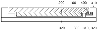
도 2를 참조하면, 본 발명의 일 실시 예에 따른 전자기기는 윈도우(100)와, 윈도우(100) 일측에 마련된 디스플레이(200)와, 디스플레이(200) 일측에 마련된 프론트 케이스(1110; 310, 320)와, 프론트 케이스(1110)의 적어도 일부에 마련되는 음향 소자로서 기능하는 압전 진동 부재(2000)를 포함할 수 있다. 여기서, 전자기기는 하측 방향으로 윈도우(100), 디스플레이(200) 및 프론트 케이스(1110)가 마련되며, 윈도우(100)와 디스플레이(200)는 밀착되어 마련될 수 있고, 디스플레이(200)와 프론트 케이스(1110) 사이에는 소정의 공간이 마련될 수 있다. 즉, 프론트 케이스(1110) 상에 윈도우(100) 및 디스플레이(200)를 포함하는 디스플레이부(1310)가 마련되고, 프론트 케이스(1110)의 적어도 일부에 접촉되도록 압전 진동 부재(2000)가 마련될 수 있다. 2, the electronic device according to an embodiment of the present invention includes a
윈도우(100)는 손가락, 스트일러스 펜 등의 객체가 접촉된다. 이러한 윈도우(100)는 빛이 투과할 수 있는 소재, 예를 들어, 광투과성 합성 수지, 강화 유리 등으로 구성될 수 있다. 윈도우(100)는 빛이 투과할 수 없는 부분을 포함하여 형성될 수 있다. 즉, 윈도우(100)는 불투명 처리되는 가장자리 영역과, 가장자리 영역에 의하여 감싸지는 중앙 영역으로 구획될 수 있다. 가장자리 영역은 프론트 케이스(1110)의 일 영역에 안착되어 지지되며, 중앙 영역은 디스플레이(200)에 대응되는 면적을 가질 수 있다. 이를 통하여 사용자는 디스플레이(200)에서 출력되는 시각 정보를 외부에서 인지할 수 있게 된다. 또한, 윈도우(100)는 접착필름(미도시)을 통해 프론트 케이스(1110)에 견고하게 고정될 수 있다. 접착필름은 디스플레이(200)와 윈도우(100) 사이로 이물질이 침투하지 못하도록 실링하며, 윈도우(100)의 가장자리 영역과 프론트 케이스(1110)의 가장자리 영역에 대응되는 루프 형상으로 이루어질 수 있다. 한편, 본 발명에 따른 전자기기는 압전 진동 부재(2000)로부터 발생되는 진동을 이용하여 소리를 전달하므로 윈도우(100)에는 음향의 방출을 위한 홀 또는 홈이 형성되지 않을 수 있다. In the
디스플레이(200)는 윈도우(100)의 후면에 배치되고, 프론트 케이스(1110)에 수용된다. 디스플레이(200)는 회로 기판(미도시)과 전기적으로 연결되어 제어부의 제어에 의해 시각 정보를 출력하도록 이루어진다. 디스플레이(200)는 윈도우(100)의 빛이 투과되는 부분에 대응되는 면적을 가질 수 있다. 이러한 디스플레이(200)는 예를 들어 액정 디스플레이(liquid crystal display, LCD), 박막 트랜지스터 액정 디스플레이(thin film transistor-liquid crystal display, TFT LCD), 유기 발광 다이오드(organic light-emitting diode, OLED), 플렉시블 디스플레이(flexible display), 3차원 디스플레이(3D display) 중에서 어느 하나가 될 수 있다.The
프론트 케이스(1110)는 윈도우(100)의 가장자리를 지지하며, 디스플레이(200)와 이격되어 그 하측에 마련될 수 있다. 즉, 프론트 케이스(1110)는 윈도우(100)의 가장자리를 지지하는 지지부(310)와, 디스플레이(200)의 하면과 이격되어 마련되며 일부가 지지부(310)와 연결되는 평판부(320)를 포함할 수 있다. 여기서, 지지부(310)는 윈도우(100)의 가장자리를 따라 수직하게 마련된 수직부와, 수직부로부터 내측으로 돌출되어 윈도우(100)의 가장자리를 지지하는 수평부를 포함할 수 있다. 따라서, 수직부가 윈도우(100)를 감싸며, 수평부가 윈도우(100)의 가장자리와 접촉되어 윈도우(100)를 지지할 수 있다. 한편, 수평부의 내측으로 디스플레이(200)가 마련될 수 있다. 결국, 지지부(310)는 "L"자 형태를 가질 수 있다. 한편, 윈도우(100) 하측의 지지부(310)의 일부 영역의 두께는 디스플레이(200)의 두께보다 두꺼울 수 있다. 따라서, 지지부(310)의 하측에 연결되는 평판부(320)가 디스플레이(200)와 소정 간격 이격되어 디스플레이(200) 하측에 마련될 수 있다. 한편, 프론트 케이스(1110)와 이격되어 그 하측에는 도 1을 이용하여 설명한 바와 같이 리어 케이스(1120)가 마련될 수 있다. 프론트 케이스(1110)와 리어 케이스(1120) 사이에 소정의 공간이 마련되고, 이러한 공간 내에 각종 전자부품들이 내장된다. 프론트 케이스(1110)와 리어 케이스(1120) 사이에는 적어도 하나의 중간 케이스(미도시)가 추가로 배치될 수도 있다. 또한, 프론트 케이스(1110)의 소정 영역, 즉 지지부(310) 또는 평판부(320)의 소정 영역에는 개구(10)가 형성될 수 있다. 개구(10)는 디스플레이(200)의 소정 영역을 노출하도록 형성될 수 있다.The
압전 진동 부재(2000)는 전자기기 내부의 회로 기판(미도시)과 전기적으로 연결되어 제어부(미도시)의 제어에 따라 진동을 발생시키도록 이루어진다. 압전 진동 부재(2000)는 진동으로 인한 공기의 떨림을 통하여 소리를 발생시키거나, 골전도(bone conduction)와 공기 전도 방식으로 소리를 전달하도록 이루어진다. 이러한 압전 진동 부재(2000)는 예를 들어 골전도 스피커, 골전도 리시버 등을 포함할 수 있다. 골전도 스피커 또는 골전도 리시버는 골전도 방식으로 소리를 전달하는 것을 말한다. 골전도란 전기적인 신호를 진동 신호로 바꾸는 변환기인 골전도 진동자를 포함하고, 소리가 고막을 통하지 않고 두개골에 전도되어 직접 내이에 전달되는 현상을 이용하는 것이다. 골전도는 공기 중의 소리가 외이도, 고막 및 청소골을 통하여 내이에 도달하여 소리로 들리는 공기전도(Air Conduction)에 대응하는 개념이다. 골전도 스피커 또는 골전도 리시버에는 골전도 진동자(Bone conduction transducer)가 부착되어 있는데, 골전도 진동자는 전기적인 신호를 진동 신호로 바꾸어 소리를 전달하는 진동 스피커의 역할을 한다. 이러한 압전 진동 부재(2000)는 압전 소자를 이용하여 구현될 수 있다. 즉, 압전 진동 부재(2000)는 압전 진동 소자를 포함할 수 있는데, 압전 진동 소자를 압전 소자를 포함하고 진동 소자를 더 포함할 수 있다. 예를 들어 압전 진동 부재(2000)는 압전 소자와, 압전 소자의 일면이 접착된 진동 소자를 포함하는 압전 진동 소자를 포함할 수 있다. 압전 소자와 진동 소자를 포함하는 압전 진동 부재의 구성에 대해서는 추후 상세히 설명하겠다. 이러한 압전 진동 부재(2000)는 압전 소자를 포함하여 판 형상으로 마련될 수 있고, 모듈 케이스 내에 구현되어 모듈화되어 마련될 수도 있다. 한편, 압전 진동 부재(2000)는 개구(10)에 삽입되며, 적어도 일부가 디스플레이(200)에 접촉되도록 형성될 수 있다. 예를 들어, 평판부(320)의 소정 영역에 개구(10)가 형성되고, 압전 진동 부재(2000)는 개구(10)에 삽입되어 적어도 일부가 디스플레이(200)에 접촉될 수 있다. 이를 위해, 압전 진동 부재(2000)는 디스플레이(200)와 대면하는 일면이 가장자리에서 중앙부로 갈수록 볼록한 형태로 형성되어 중앙부, 즉 가장 볼록한 영역이 디스플레이(200)에 접촉될 수 있다. 압전 진동 부재(2000)는 프론트 케이스(1110)에 장착되어 발생하는 진동을 윈도우(100)로 전달하도록 이루어진다. 즉, 압전 진동 부재(2000)가 장착되는 프론트 케이스(1110)의 평판부(320)는 지지부(320)와 연결되고, 지지부(320)는 윈도우(100)와 연결되므로 압전 진동 부재(2000)의 진동은 프론트 케이스(1110)의 평탄부(320) 및 지지부(310)를 거쳐 윈도우(100)로 전달되며, 사용자는 통화시에 귀가 윈도우(100)에 접촉됨에 따라 진동을 통하여 소리를 들을 수 있다.The piezoelectric vibrating
한편, 본 발명의 전자기기는 윈도우(100), 디스플레이(200), 프론트 케이스(1110) 및 압전 진동 부재(2000)에 더하여 도시하지 않은 회로 기판과, 도 1에 도시된 리어 케이스(1120) 등을 더 포함할 수 있다. 리어 케이스(1120)는 프론트 케이스(1110)에 결합되어 압전 진동 부재(2000)를 덮도록 배치되며, 리어 케이스(1120)에는 압전 진동 부재(2000)의 주변 공기를 배출하는 배출홀(미도시)이 형성될 수 있다. 이를 통하여, 압전 진동 부재(2000)의 후면에서 발생하는 울림 현상이 완화 또는 제거될 수 있다. 또한, 리어 케이스(1120)를 덮도록 커버 케이스(1130)가 마련될 수 있다. 따라서, 압전 진동 부재(2000)가 리어 케이스(1120) 또는 커버 케이스(1130)에도 마련될 수 있다. 즉, 압전 진동 부재(2000)는 프론트 커버(1110) 뿐만 아니라 리어 케이스(1120) 또는 커버 케이스(1130)에도 마련될 수 있다.The electronic apparatus of the present invention includes a circuit board not shown in addition to the
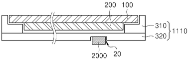
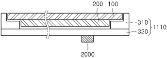
또한, 압전 진동 부재(2000)는 다양한 방법으로 프론트 케이스(1110) 또는 프론트 케이스(1110)를 통해 디스플레이(200)에 접촉될 수 있다. 즉, 도 2를 이용하여 설명된 실시 예 뿐만 아니라 다양한 실시 예가 가능한데, 압전 진동 부재(2000)의 접촉 방식의 다양한 실시 예를 도 3 내지 도 8을 이용하여 설명하면 다음과 같다.Further, the
도 3에 도시된 바와 같이, 압전 진동 부재(2000)는 적어도 일면이 평탄하게 마련되고, 평탄면으로부터 프론트 케이스(1110)의 평판부(320)에 형성된 개구(10)에 삽입되어 디스플레이(200)에 접촉될 수 있다. 즉, 압전 진동 부재(2000)는 평탄면이 디스플레이(200)에 접촉될 수 있다.3, at least one surface of the piezoelectric vibrating
또한, 도 4에 도시된 바와 같이 압전 진동 부재(2000)는 상측 일부가 프론트 케이스(1110)의 평판부(320)에 걸쳐 개구(10)에 삽입될 수 있다. 즉, 압전 진동 부재(2000)는 개구(10)에 삽입되는 부분과, 이보다 폭이 더 넓어 개구(10)에 삽입되지 않고 개구(10) 입구의 평판부(320)에 지지되는 영역을 포함할 수 있다. 따라서, 압전 진동 부재(2000)는 적어도 일부가 평판부(320)에 지지되어 적어도 일부가 개구(10)에 삽입될 수 있다. 이때, 지지 영역은 개구(10)에 삽입되는 영역보다 두께가 얇을 수 있고, 지지 영역에 접착 부재 등이 마련되어 압전 진동 부재(2000)가 평판부(320)에 접착될 수 있다.4, an upper portion of the piezoelectric vibrating
그리고, 도 5에 도시된 바와 같이 프론트 케이스(1110)의 평판부(320)에 홈(20)이 형성되고 홈(20) 내에 압전 진동 부재(2000)가 삽입될 수 있다. 여기서, 개구(10)는 지지부(310) 또는 평판부(320)를 통해 디스플레이(200)가 노출되도록 지지부(310) 또는 평판부(320)를 관통하도록 형성되지만, 홈(20)은 소정 두께가 잔류하도록 지지부(310) 또는 평판부(320)의 일부가 제거되어 형성될 수 있다.5,
물론, 도 6에 도시된 바와 같이 개구(10) 또는 홈(20)이 형성되지 않고 프론트 케이스(1110)의 일 면에 압전 진동 부재(2000)가 마련될 수도 있다. 즉, 디스플레이(200)에 대면하지 않는 평판부(320)의 타면의 소정 영역에 압전 진동 부재(2000)가 마련될 수 있다.Of course, the
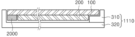
또한, 압전 진동 부재(2000)는 윈도우(100)의 일 영역에 직접 부착될 수도 있다. 즉, 도 7에 도시된 바와 같이 디스플레이(200)가 마련되지 않은 영역, 즉 디스플레이(200)의 외측 영역에 압전 진동 부재(2000)가 마련되고, 이 경우 프론트 케이스(1110)는 지지부(310) 형상이 변형될 수 있다. Further, the
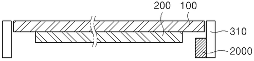
한편, 프론트 케이스(1110)는 형상이 변형되고, 프론트 케이스(1110)의 소정 영역에 압전 진동 부재(2000)가 마련될 수 있다. 예를 들어, 도 8에 도시된 바와 같이 프론트 케이스(1110)는 윈도우(100)의 테두리에 접촉되어 고정되어 윈도우(100)를 감싸도록 마련되고, 프론트 케이스(1110)의 일 영역에 압전 진동 부재(2000)가 마련될 수 있다. 예를 들어, 압전 진동 부재(2000)는 윈도우(100) 하측의 디스플레이(200)가 형성되지 않은 영역의 프론트 케이스(1110)에 접촉되어 마련될 수 있다. 또한, 도 9에 도시된 바와 같이 프론트 케이스(1110)는 평판부(320)가 마련되지 않을 수 있는데, 이 경우 윈도우(100)를 지지하는 지지부(310)의 하측에 압전 진동 부재(2000)가 마련될 수 있다. 즉, 지지부(310)의 수평부는 일 면이 윈도우(100)를 접촉하여 지지하고, 타면에 압전 진동 부재(2000)가 마련될 수 있다.On the other hand, the shape of the
도 10은 본 발명의 제 1 실시 예에 따른 압전 진동 부재(2000)의 단면도이고, 도 11은 본 발명의 제 2 실시 예에 따른 압전 진동 부재(2000)의 단면도이다. 또한, 도 12 및 도 13은 본 발명의 제 2 실시 예의 변형 예에 따른 압전 진동 부재(2000)의 분리 사시도이다.10 is a cross-sectional view of a piezoelectric vibrating
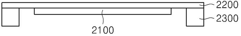
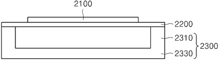
도 10을 참조하면, 압전 진동 부재(2000)는 진동판(2200)과, 진동판(2200)의 적어도 일면에 마련된 압전 소자(2100)와, 진동판(2200)의 적어도 두 영역에 마련된 지지 부재(2300)을 더 포함할 수 있다. 또한, 도 11 내지 도 13에 도시된 바와 같이, 진동판(2200)의 일면 상에 마련된 웨이트 부재(2400)를 더 포함할 수도 있다.10, the
1. 압전 소자1. Piezoelectric element
압전 진동 부재(2000)는 전압 인가에 따라 굽힘 응력이 발생하는 역압전 효과에 의해 진동을 발생시킨다. 즉, 압전 소자(2100)는 인가되는 전압에 따라 수직 또는 수평 방향으로 신축 운동을 하고, 진동판(2200)은 이를 굽힘 변형으로 변형하여 수직 방향으로 진동을 발생시킨다. 여기서, 압전 소자(2100)는 베이스와, 베이스의 적어도 일면 상에 마련된 적어도 하나의 압전층 및 내부 전극을 포함할 수 있다. 이러한 압전 소자(2100)에 대해서는 도 14 및 15 등을 이용하여 추후 더욱 상세히 설명한다. 압전 소자(2100)는 접착제 등을 이용하여 진동판(2200)의 적어도 일면에 부착된다. 이때, 진동판(2200)의 양측이 동일 길이로 잔류하도록 압전 소자(2100)는 진동판(2200)의 중앙부에 부착될 수 있다. 또한, 압전 소자(2100)는 진동판(2200)의 상면에 부착될 수 있고, 진동판(2200)의 하면에 부착될 수도 있으며, 진동판(2200)의 상하 양면에 부착될 수도 있다. 즉, 본 실시 예는 압전 소자(2100)가 진동판(2200)의 하면에 부착되는 경우를 도시하여 설명하고 있지만, 압전 소자(2100)는 진동판(2200)의 상면에 부착될 수도 있고, 진동판(2200)의 상면 및 하면에 부착될 수도 있다. 여기서, 압전 소자(2100)와 진동판(2200)은 접착 이외에 다양한 방법으로 고정될 수 있다. 예를 들어, 진동판(2200)과 압전 소자(2100)를 점착제를 이용하여 점착하고, 진동판(2200)과 압전 소자(2100)의 측면을 접착제 등을 이용하여 접착함으로써 고정할 수도 있다.The piezoelectric vibrating
2. 진동판2. Diaphragm
진동판(2200)은 금속, 플라스틱, 수지 등을 이용하여 제작할 수 있고, 서로 다른 이종의 소재를 적층하여 적어도 2중 구조를 이용할 수 있다. 또한, 진동판(2200)은 폴리머계 또는 펄프계 물질을 이용할 수 있다. 예를 들어, 진동판(2200)은 수지 필름을 이용할 수 있는데, 에틸렌 플로필렌 고무계, 스티렌 부타디엔 고무계 등 경도가 40∼130(Rockwell Hardness, ASTM D785 R scale), 바람직하게는 50∼120일 수 있다. 이러한 압전 소자(2100) 및 진동판(2200)은 대략 직사각형의 판 형상으로 제작된다. 즉, 압전 소자(2100) 및 진동판(2200)은 각각 소정의 길이, 너비 및 두께를 가지고, 서로 대향되는 일면 및 타면을 갖는 형상으로 제작된다. 이때, 진동판(2200)이 압전 소자(2100)보다 길게 제작될 수 있다. 또한, 진동판(2200)은 웨이트 부재(2400)와 같은 길이로 제작될 수 있다. 이러한 압전 진동 부재(2000)는 진동판(2200)의 일면이 압전 소자(2100)의 일면과 접착되고, 진동판(2200)의 타면이 웨이트 부재(2400)의 일부와 접촉된다. 즉, 진동판(2200)의 하면에 압전 소자(2100)가 접착되고, 진동판(2200)의 상면에 웨이트 부재(2400)의 일부가 결합될 수 있다. 또한, 압전 소자(2100)가 진동판(2200)의 상면에 부착되는 경우 압전 소자(2100)와 웨이트 부재(2400)가 접촉되어 결합될 수도 있다. 이때, 압전 진동 부재(2000)와 웨이트 부재(2400)는 접착에 의해 고정될 수 있다. 또한, 진동판(2200)은 압전 소자(2100)와 접착된 영역 이외의 소정 영역이 외측으로 연장되어 형성될 수 있다.The
3. 지지 부재 3. Support member
지지 부재(2300)는 진동판(2200)의 일면에 접촉되어 마련될 수 있다. 또한, 지지 부재(2300)는 일면이 진동판(2200)과 접촉되고 타면이 전자기기(1000)의 적어도 일 영역에 접촉될 수 있다. 즉, 지지 부재(2300)는 압전 진동 부재(2000)와 전자기기(1000) 사이에 마련되며, 압전 진동 부재(2000)를 전자기기(1000) 상에 지지할 수 있다. 또한, 지지 부재(2300)는 압전 진동 부재(2000)에서 발생된 진동을 전자기기(1000)에 전달할 수 있다. 이러한 지지 부재(2300)는 진동판(2200)의 적어도 일 영역에 마련될 수 있다. 예를 들어, 지지 부재(2300)는 진동판(2200)의 길이 방향의 두 말단부에 각각 마련될 수 있다. 또한, 지지 부재(2300)는 진동판(2200)의 가장자리를 따라 대략 "ㅁ"자 형상으로 마련될 수도 있다. 물론, 지지 부재(2300)는 진동판(2200)의 가장자리의 두 영역의 이상의 영역에 소정 간격 이격되어 마련될 수 있다. 한편, 이러한 지지 부재(2300)의 내측으로 압전 소자(2100)가 마련될 수 있다. 즉, 도 10 및 도 11에 도시된 바와 같이 압전 소자(2100)는 지지 부재(2300)의 내측에 동일 수직 선분을 이루는 영역으로부터 내측으로 마련될 수 있다. 다시 말하면, 압전 소자(2100)는 지지 부재(2300) 사이의 공간보다 같거나 작은 크기로 마련될 수 있다. 이때, 압전 소자(2100)의 적어도 일부가 지지 부재(2300)와 중첩되는 영역 상에 마련될 경우 특성, 예를 들어 음압 및 저주파 특성의 적어도 하나가 저하될 수 있으므로, 압전 소자(2100)는 지지 부재(2300) 내측에 마련되는 것이 바람직하다. 한편, 지지 부재(2300)는 소정의 탄성을 갖는 연성 물질로 마련될 수 있다. 즉, 지지 부재(2300)는 압축 및 복원이 가능한 물질을 이용할 수 있다. 이러한 지지 부재(2300)는 경도가 5∼95(ASTM D2240 Shore A)인 물질, 바람직하게는 40∼90인 물질로 형성할 수 있다. 또한, 지지 부재(2300)의 경도는 진동판(2200)의 경도보다 같거나 낮다. 이를 위해 지지 부재(2300)은 예를 들어 실리콘, 겔, 고무, 우레탄 등을 이용하여 형성할 수 있다. 지지 부재(2300)가 경도가 높은 물질로 이루어진 경우 저역 특성이 저하되는 등의 문제가 발생할 수 있다.The
4. 4. 웨이트wait 부재 absence
웨이트 부재(2400)는 도 11에 도시된 바와 같이 진동판(2200)의 소정 영역, 예를 들어 중앙 영역에 마련될 수 있다. 이때, 웨이트 부재(2400)는 압전 소자(2100)보다 짧은 길이로 마련될 수 있다. 그러나, 웨이트 부재(2400)는 도 12 및 도 13에 도시된 바와 같이 압전 소자(2100)보다 길거나 같은 길이로 마련될 수도 있다. 이렇게 진동판(2200)에 웨이트 부재(2400)가 결합되어 웨이트 부재(2400)의 무게가 실리면 진동체의 무게가 늘어난 결과가 되어 압전 진동 부재(2000)가 단독으로 진동할 때에 비해 공진 주파수는 감소하는 대신에 반면 진동력은 강화된다. 특히, 교류 구동 전압의 특정 주파수에서는 진동력이 최대로 증폭된다. 공진 주파수는 압전 진동 부재(2000), 웨이트 부재(2400) 등의 각 구성 요소의 물리적 재원과 물성적 특징에 따라 다른 값을 가질 수 있다. 진동체는 자신의 고유 진동수에서 진동을 할 때 가장 큰 진동을 일으킨다. 여기서, 압전 진동 부재(2000)의 두께를 얇게 하기 위해 웨이트 부재(2400)의 두께를 줄이고, 적어도 둘 이상의 웨이트 부재(2400)가 구비되도록 할 수 있다. 예를 들어, 도 11의 (a)에 도시된 바와 같이 하나의 웨이트 부재(2400)를 이용하는 경우에 비해 도 11의 (b)에 도시된 바와 같이 두께를 1/2 내지 1/3 등으로 줄이고, 이렇게 두께가 얇아진 웨이트 부재(2400)를 두개 또는 세개 결합하여 구성할 수도 있다. 따라서, 두께를 줄이면서 웨이트 부재(2400)의 질량은 그대로 유지하여 하나의 큰 웨이트 부재(2400)를 이용하는 경우와 동일하게 진동력을 향상시킬 수 있고, 두께를 줄일 수 있다.The
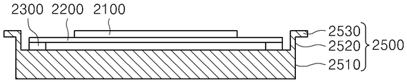
한편, 웨이트 부재(2400)는 도 12 및 도 13에 도시된 바와 같이 소정의 길이와 너비, 그리고 두께를 갖는 대략 육면체의 형상을 갖는다. 또한, 웨이트 부재(2400)는 진동판(2000) 측으로 접촉부(2410)가 형성되고, 접촉부(2410)는 진동판(2000)과 접촉된다. 즉, 접촉부(2410)는 진동판(2000)의 일면과 대면하는 웨이트 부재(2400)의 두께 방향의 일면의 중앙부에 마련될 수 있으며, 그에 따라 진동판(2000)의 중앙부에 접촉될 수 있다. 접촉부(2410)는 수평을 이루도록 평탄하게 마련된 웨이트 부재(2400)의 일면 중앙부에 돌출되어 마련될 수 있고, 웨이트 부재(2400)의 일면이 가장자리로부터 중앙부로 소정 각도로 경사지게 형성되고 중앙부의 가장 높은 부분이 접촉부(2410)가 되어 진동판(2200)와 접촉될 수 있다. 이때, 접촉부(2410)와 진동판(2200)은 접착제 등에 따라 접착되어 고정될 수 있다. 즉, 웨이트 부재(2400)는 접촉부(2410)와 진동판(2200) 사이에 접착제가 마련되어 웨이트 부재(2400)가 압전 진동 부재(2000)에 1차 고정될 수 있다. 따라서, 접촉부(2410)가 진동판(2200)과 접촉되고, 웨이트 부재(2400)의 나머지 영역은 진동판(2200)과 이격될 수 있다. 그런데, 접착제의 종류 및 그에 따른 특성에 따라 접착제를 두껍게 도포해야 할 수도 있는데, 접착제 도포 두께에 따라 압전 진동 부재(2000)와 웨이트 부재(2400)의 간격이 멀어지고, 그에 따라 압전 진동 장치의 두께가 증가할 수 있다. 따라서, 접착제가 도포되는 영역, 즉 접촉부(2410)는 접착제의 도포 두께에 따라 내부로 움푹 파인 오목부(미도시)가 형성되고, 오목부 내측에 접착제가 도포될 수 있다. 한편, 접촉부(2410)는 웨이트 부재(2400)의 중앙부에 위치하지 않을 수도 있고 중앙부로부터 30% 이내에서 이동될 수 있다. 그에 따라 진동 주파수 및 변위를 조절할 수 있다. 이렇게 진동판(2200)과 결합되는 웨이트 부재(2400)는 진동판(2200)의 진동에 의해 그와 함께 진동하면서 자신의 무게를 그 진동에 실어준다. 한편, 웨이트 부재(2400)의 측면 및 상면에는 고정 부재(2500)가 수용되어 결합되는 수용 홈(2420)이 형성될 수 있다. 즉, 고정 부재(2500)가 접촉되는 웨이트 부재(2400)의 영역에는 오목하게 패인 수용 홈(2420)이 형성되고, 수용 홈(2420) 내에 고정 부재(2500)가 삽입되어 수용될 수 있다. 이러한 수용 홈(2420)은 고정 부재(2500)의 두께 정도의 깊이와 고정 부재(2500)의 폭 정도의 폭으로 형성될 수 있다. 따라서, 고정 부재(2500)가 수용 홈(2420)에 삽입된 후 웨이트 부재(2400)의 측면 및 상면은 고정 부재(2500)와 평면을 이룰 수 있다. 물론, 수용 홈(2420)은 고정 부재(2500)의 두께보다 큰 깊이로 형성될 수도 있고 작은 깊이로 형성될 수도 있다. 그러나, 수용 홈(2420)의 폭은 고정 부재(2500)의 폭으로 형성되고, 그에 따라 웨이트 부재(2400)가 움직이지 않도록 하는 것이 바람직하다. 이렇게 고정 부재(2500)가 수용 홈(2420) 내에 삽입되어 웨이트 부재(2400)를 더욱 견고하게 고정할 수 있다.On the other hand, the
5. 고정 부재5. Fixing member
고정 부재(2500)는 압전 진동 부재(2000)의 적어도 일 영역으로부터 웨이트 부재(2400)를 감싸도록 마련될 수 있다. 예를 들어, 고정 부재(2500)는 진동판(2200)의 X 방향의 두 측면, 즉 장변으로부터 연장되어 마련된 제 1 및 제 2 고정 부재(2510, 2520)를 포함할 수 있다. 이러한 고정 부재(2500)는 진동판(2200)과 일체로 마련될 수 있다. 물론, 고정 부재(2500)는 진동판(2200)과 별도로 제작된 후 진동판(2200)의 일 영역에 용접 등의 방법으로 고정될 수도 있다. 그러나, 고정 부재(2500)는 진동판(2200)과 일체로 제작되는 것이 바람직하다. 이러한 고정 부재(2500)는 웨이트 부재(2400)의 측면 및 상면을 감싸도록 형성되어 웨이트 부재(2400)는 압전 진동 부재(2000) 상에 고정시킬 수 있다. 즉, 고정 부재(2500)는 웨이트 부재(2400)의 측면 및 상면에 접촉되어 꺾어져 웨이트 부재(2400)를 접촉되어 감싸도록 형성될 수 있다. 웨이트 부재(2400)는 압전 진동 부재(2000) 상에 접착제 등에 의해 1차 고정되는데, 고정 부재(2500)가 웨이트 부재(2400)를 감싸 고정함으로써 웨이트 부재(2400)를 더욱 견고하게 고정할 수 있다. 한편, 고정 부재(2500)의 꺾어지는 부분의 적어도 일부는 고정 부재(2500)의 일부가 제거되어 다른 영역보다 폭이 좁거나 얇게 형성될 수 있다. 즉, 도 12에 도시된 바와 같이 진동판(2200)의 측면과 접촉되는 부분에 소정 폭이 제거되어 개구가 형성될 수 있다. 이렇게 고정 부재(2500)의 적어도 일부분이 제거됨으로써 고정 부재(2500)의 꺾임을 용이하게 할 수 있고, 그에 따라 웨이트 부재(2400)를 더욱 밀착하여 고정할 수 있다. 이러한 고정 부재(2500)는 진동판(2200)과 동일 재질로 형성될 수 있으며, 예를 들어 금속 재질로 형성될 수 있다. 한편, 고정 부재(2500)는 진동판(2200)의 양측에 한쌍 형성될 수도 있고, 둘 이상 복수의 쌍으로 형성될 수도 있다. 즉, 고정 부재(2500)는 진동판(2200)의 일 측면 및 이와 대향되는 타 측면에 각각 하나씩 형성될 수도 있고, 진동판(2200)의 일 측면 및 이와 대향되는 타 측면에 소정 간격 이격되어 복수 형성될 수도 있다. 고정 부재(2500)가 복수의 쌍으로 형성됨으로써 웨이트 부재(2400)를 복수의 영역에서 고정할 수 있고, 그에 따라 한쌍으로 고정하는 경우에 비해 웨이트 부재(2400)를 더욱 견고하게 고정할 수 있다. 한편, 고정 부재(2500)는 웨이트 부재(2400)의 길이에 대해 5% 내지 50%의 폭으로 형성될 수 있다. 즉, 고정 부재(2500)의 폭은 웨이트 부재(2400) 길이의 5% 내지 50%로 형성될 수 있다. 이는 하나의 고정 부재(2500)의 폭이 웨이트 부재(2400) 길이의 5% 내지 50%일 수 있고, 복수의 고정 부재(2500)의 폭의 합이 웨이트 부재(2400) 길이의 5% 내지 50%일 수 있다. 또한, 고정 부재(2500)는 서로 맞닿는 부분이 다양한 형상으로 형성될 수 있다. 즉, 제 1 고정 부재(2510)의 일 영역에 돌출부가 마련되고 타 영역에 오목부가 마련되며, 이와 대향되는 제 2 고정 부재(2520)는 제 1 고정 부재(2510)의 돌출부 및 오목부에 각각 대향되어 오목부 및 돌출부가 마련될 수 있다. 또한, 제 1 고정 부재(2510)에는 예를 들어 중앙부에 오목부가 마련되고 이에 대향되어 제 2 고정 부재(252)에는 볼록부가 마련될 수 있다. 그리고, 제 1 고정 부재(251)에는 둘 이상의 오목부가 마련되고 이에 대향되어 제 2 고정 부재(2520)에는 둘 이상의 볼록부가 마련될 수 있다. 또한, 제 1 및 제 2 고정 부재(2510, 2520)는 각각의 말단이 톱니 모양으로 형성되고 이들이 대향되어 결합될 수 있다. 이렇게 제 1 및 제 2 고정 부재(2510, 2520)의 서로 맞닿는 말단부를 다양한 형상으로 형성함으로써 제 1 및 제 2 고정 부재(2510, 2520)의 대면하는 면적을 증가시킬 수 있고, 그에 따라 웨이트 부재(2400)의 고정력을 더욱 증가시킬 수 있다. 한편, 고정 부재(2500)와 웨이트 부재(2400) 사이, 즉 고정 부재(2500)와 수용 홈(2420) 사이에는 접착제 또는 쿠션재가 마련될 수 있다. 접착제가 마련됨으로써 고정 부재(2500)와 웨이트 부재(2400)의 결합력을 향상시킬 수 있다. 또한, 쿠션재가 마련됨으로써 고정 부재(2500)와 웨이트 부재(2400)의 결합에 의한 충격을 완화시킬 수 있고, 진동에 의한 소음을 감소시킬 수 있다.The fixing
한편, 압전 진동 부재(2000)의 적어도 일부에 코팅층(미도시)이 더 형성될 수 있다. 코팅층은 파릴렌(parylene) 등의 방수 재료를 이용하여 형성될 수 있다. 파릴렌은 압전 소자(2100)가 진동판(2200) 상에 접합된 상태에서 압전 소자(2100)의 상면 및 측면과 압전 소자(2100)에 의해 노출된 진동판(2200)의 상면 및 측면에 형성될 수 있다. 즉, 파릴렌은 압전 소자(2100) 및 진동판(2200)의 상면 및 측면에 형성될 수 있다. 또한, 파릴렌은 압전 소자(2100)가 진동판(2200) 상에 접합된 상태에서 압전 소자(2100)의 상면 및 측면과 진동판(2200)의 상면, 측면 및 하면에 형성될 수 있다. 즉, 파릴렌은 압전 소자(2100) 및 진동판(2200)의 상면, 측면 및 하면에 형성될 수 있다. 그리고, 압전 소자(2100)가 진동판(2200)의 중앙부에 형성된 개구 상에 마련되는 경우 파릴렌은 압전 소자(2100)의 상면, 측면 및 개구에 의해 노출된 하면 상에 형성되고, 이와 동시에 진동판(2200)의 상면, 측면 및 하면에 형성될 수 있다. 이렇게 파릴렌이 압전 소자(2100) 및 진동판(2200)의 적어도 일면에 형성됨으로써 습기 침투를 방지할 수 있고 산화를 방지할 수 있다. 또한, 폴리머 등의 얇은 재질의 진동판(2200)을 이용하여 발생되는 편진동을 개선할 수 있고, 진동 소자의 경도 증가에 의한 응답 속도가 향상되어 깊은 음향 특성을 완화시키고 고음역을 안정화시킬 수 있다. 그리고, 파릴렌의 코팅 두께에 따라 공진 주파수를 조절할 수 있다. 물론, 파릴렌은 압전 소자(2100)에만 코팅될 수도 있는데, 압전 소자(2100)의 상면, 측면 및 하면에 코팅될 수 있고, 압전 소자(2100)와 연결되어 압전 소자(2100)에 전원을 공급하기 위한 FPCB에 코팅될 수도 있다. 파릴렌이 압전 소자(2100)에 형성됨으로써 압전 소자(2100)의 수분 침투를 방지할 수 있고 산화를 방지할 수 있다. 또한, 형성 두께를 조절함으로써 공진 주파수를 조절할 수 있다. 한편, 파릴렌이 FPCB 상에 형성되는 경우 FPCB와 솔더, 소자 이음부에서 발생되는 이상음을 개선할 수도 있다. 이러한 파릴렌은 압전 소자(2100) 또는 진동판(2200)의 재질과 특성에 따라 두께를 다르게 하여 코팅될 수 있는데, 압전 소자(2100) 또는 진동판(2200)의 두께보다 얇게 형성될 수 있으며, 예를 들어 0.1㎛∼10㎛의 두께로 형성될 수 있다. 이렇게 파릴렌을 코팅하기 위해 예를 들어 파릴렌을 기화기(Vaporizer)에서 1차 가열하여 기화시켜 다이머(dimer) 상태로 만든 후 2차 가열하여 모노머(Monomer) 상태로 열분해시키고, 파릴렌을 냉각시키면 파릴렌은 모노머 상태에서 폴리머 상태로 변환되어 압전 진동 부재(2000)의 적어도 일면 상에 코팅될 수 있다.On the other hand, a coating layer (not shown) may be further formed on at least a part of the piezoelectric vibrating
실험 예Experimental Example
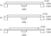
압전 소자(2100)의 위치 및 지지 부재(2300)의 재질에 따른 압전 진동 부재(2000)의 특성을 실험하였다. 먼저, 압전 소자(2100)의 위치에 따른 특성을 실험하기 위해 비교 예 및 본 발명의 실시 예들에 따른 압전 진동 부재를 구현하였다. 즉, 비교 예에 따른 압전 진동 부재는 도 14의 (a)에 도시된 바와 같이 압전 소자(2100)가 지지 부재(2300) 상에 적어도 일부 중첩되도록 마련하였고, 실시 예 1에 따른 압전 진동 부재는 도 14의 (b)에 도시된 바와 같이 압전 소자(2100)의 가장자리가 지지 부재(2300)의 내측면에 수직을 이루도록 마련하였다. 또한, 실시 예 2에 따른 압전 진동 부재는 도 14의 (c)에 도시된 바와 같이 압전 소자(2100)가 지지 부재(2300)의 내측에 위치하도록 마련하였다. 즉, 비교 예는 압전 소자(2100)의 길이가 지지 부재(2300) 사이의 거리보다 길게 마련하였으며, 실시 예 1은 압전 소자(2100)의 길이가 지지 부재(2300) 사이의 거리와 같게 마련하였으며, 실시 예 2는 압전 소자(2100)의 길이가 지지 부재(2300) 사이의 거리보다 짧게 마련하였다. 한편, 비교 예와 실시 예 1 및 2는 압전 소자(2100)의 위치 및 길이만 다를 뿐 나머지는 동일한 조건에서 실험하였다. 즉, 압전 소자(2100)의 재질 및 두께, 진동판(2200)의 재질 및 크기, 지지 부재(2300)의 재질 및 크기, 그리고 웨이트 부재(2400)의 재질 및 크기 등을 모두 동일하게 하였다.The characteristics of the piezoelectric vibrating
이러한 비교 예 및 실시 예들에 따른 압전 진동 부재의 특성을 도 15에 도시하였다. 도시된 바와 같이 비교 예에 비해 실시 예 1 및 2의 음압이 상승함을 알 수 있다. 또한, 실시 예 2가 실시 예 1에 비해 음압이 상승함을 알 수 있다. 이로부터 압전 소자(2100)가 지지 부재(2300)로부터 멀수록 음압이 상승함을 알 수 있다. 즉, 도시하지는 않았지만, 실시 예 2보다 더 작은 압전 소자(2100)를 이용하는 경우 음압 특성은 더 좋아지게 된다. 또한, 제시하지는 않았지만, 비교 예보다 압전 소자(2100)의 크기가 커 지지 부재(2300)와 압전 소자(2100)가 완전히 중첩되는 경우 비교 예와 유사하거나 더 낮은 음압 특성을 나타낸다.The characteristics of the piezoelectric vibrating member according to the comparative examples and the embodiments are shown in Fig. As can be seen, the sound pressure of Examples 1 and 2 is increased as compared with Comparative Example. In addition, it can be seen that the sound pressure of Example 2 is higher than that of Example 1. From this, it can be seen that the sound pressure increases as the
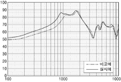
도 16은 지지 부재의 재질에 따른 주파수 특성을 나타낸 그래프이다. 비교 예는 지지 부재로서 경도가 높은 폴리카보네이트(Polycarbonate; PC)를 이용하였고, 실시 예는 지지 부재로서 경도가 낮은 실리콘을 이용하였다. 지지 부재의 재질 이외에 나머지 조건은 비교 예 및 실시 예를 동일하게 하였다. 즉, 압전 소자(2100)의 재질, 길이 및 두께, 진동판(2200)의 재질 및 크기, 지지 부재(2300)의 재질 및 크기, 웨이트 부재(2400)의 재질 및 크기, 그리고 압전 소자(2100)가 지지 부재(2300) 내측에 동일하게 위치하는 등을 모두 조건을 동일하게 하였다. 도 16에 도시된 바와 같이 경도가 높은 지지 부재를 이용한 비교 예에 비해 경도가 낮은 지지 부재를 이용한 실시 예의 저역 특성이 향상됨을 알 수 있다.16 is a graph showing frequency characteristics according to the material of the support member. In the comparative example, polycarbonate (PC) having high hardness was used as a support member, and silicon having a low hardness was used as a support member in the Examples. The remaining conditions except for the material of the support member are the same as those of the comparative example and the embodiment. The length and thickness of the
이어서, 본 발명의 압전 진동 부재(2000)로 이용되는 압전 소자(2100)에 대해 도면을 이용하여 상세히 설명하면 다음과 같다. 도 17 및 도 18은 본 발명의 일 예에 따른 압전 소자의 사시도 및 단면도이고, 도 19는 본 발명의 다른 실시 예에 따른 압전 소자의 단면도이다. 또한, 도 20 및 도 21은 본 발명의 다른 에에 따른 압전 소자를 설명하기 위한 도면이다.Next, the
2.1. 압전 소자의 일 예2.1. An example of a piezoelectric device
도 17에 도시된 바와 같이, 압전 소자(2100)는 소정의 두께를 갖는 판 형상으로 마련될 수 있다. 예를 들어, 압전 소자(2100)는 0.1㎜∼1㎜의 두께를 가질 수 있다. 그러나, 압전 진동 장치의 크기 등에 따라 압전 소자(2100)의 두께는 상기 두께 범위 이하이거나 이상일 수 있다. 또한, 압전 소자(2100)는 대략 사각형의 형상을 가질 수 있는데, 이때 길이가 폭보다 길거나 같을 수 있다. 예를 들어, X 방향으로의 길이와 Y 방향으로의 폭의 비율이 5:5∼9:1일 수 있다. 이때, 압전 소자(2100)는 진동판(2200)보다 작거나 같은 사이즈로 마련될 수 있는데, X 방향으로의 길이가 진동판(2200)의 길이보다 짧거나 같고, Y 방향으로의 폭이 진동판(2200)의 폭보다 짧거나 같도록 마련될 수 있다. 물론, 압전 소자(2100)는 압전 진동 장치의 형태에 따라 원형, 타원형 등 다양한 형상으로 마련될 수 있다.As shown in Fig. 17, the
이러한 압전 소자(2100)는 도 18에 도시된 바와 같이 베이스(2110)와, 베이스(2110)의 적어도 일면 상에 마련된 적어도 하나의 압전층(2120)과, 압전층(2120) 상에 형성된 적어도 하나의 내부 전극(2130)을 포함할 수 있다. 즉, 압전 소자(2100)는 베이스(2110)의 양면에 압전층(2120)이 형성된 바이모프 타입으로 형성될 수도 있고, 베이스(2110)의 일면에 압전층(2120)이 형성된 유니모프 타입으로 형성될 수도 있다. 또한, 변위와 진동력을 증가시키고, 저전압 구동을 가능하게 하기 위해 베이스(2110)의 일면 상에 압전층(2120)을 복수로 적층하고 유니모프 타입으로 형성할 수도 있다. 예를 들어, 도 18에 도시된 바와 같이 베이스(2110)의 일면 및 타면 상에 복수의 압전층(2121 내지 2128; 2120)이 적층 형성되고, 압전층(2120) 사이에 도전층이 형성되어 복수의 내부 전극(2131 내지 2138; 2130)이 형성될 수 있다. 또한, 도전층은 압전층(2120)의 표면에 형성되어 표면 전극(2139)이 형성될 수 있다. 한편, 내부 전극(2130)의 적어도 하나는 베이스(2110)의 표면 상에 형성될 수도 있는데, 이때 베이스(2110)는 절연성 물질로 이루어질 수 있다. 또한, 압전 소자(2100)는 내부 전극(2130)과 연결되도록 적층체의 외부에 형성된 외부 전극(2141, 2142; 2140)을 더 포함할 수도 있다.18, the
베이스(2110)는 압전층(2120)이 적층된 구조를 유지하면서 진동이 발생할 수 있는 특성을 갖는 물질을 이용할 수 있다. 예를 들어, 베이스(2110)는 금속, 플라스틱, 절연성 세라믹 등을 이용할 수 있다. 한편, 베이스(2110)는 금속, 플라스틱, 절연성 세라믹 등의 압전층(2120)과 이종의 물질을 이용하지 않을 수 있다. 즉, 베이스(2110)는 분극되지 않은 압전층을 이용하여 마련될 수도 있다. 이때, 베이스(2110)가 분극되지 않은 압전층 또는 금속으로 마련될 경우 베이스(2110)의 표면에는 내부 전극(2130)이 형성되지 않을 수 있다. 한편, 분극되지 않은 압전층으로 마련된 베이스(2110)는 그 상측 및 하측에서 역방향으로 동작하는 각각의 압전층(2120)의 경계로 작용할 수도 있다. 예를 들어, 베이스(2110)를 기준으로 하측의 압전층들(2121 내지 2124)이 수축할 때 상측의 압전층들(2125 내지 2128)이 팽창하여 서로 반대 방향으로 동작할 수 있다. 베이스(2110)는 압전 소자(2100) 전체 두께 대비 1/3 내지 1/150의 두께로 마련될 수 있다. 예를 들어, 압전 소자(2100)의 두께가 300㎛일 경우 베이스(2110)의 두께는 2㎛ 내지 100㎛일 수 있다. 이때, 베이스(2110)의 두께는 압전층(2120) 전체의 두께보다 얇고, 복수로 적층된 압전층(2120) 각각의 두께보다 얇거나 같을 수 있다. 물론, 베이스(2110)의 두께가 압전층(2120) 각각의 두께보다 두꺼울 수도 있다. 그러나, 베이스(2110)가 두꺼울수록 압전층(2120)의 두께가 얇아지거나 압전층(2120)의 적층 수가 적어지므로 압전 현상이 적게 발생할 수 있다. 따라서, 베이스(2110)의 두께는 압전층(2120) 전체의 두께보다 얇고 복수로 이루어진 압전층(2120) 각각의 두께보다 얇거나 같은 것이 바람직하다. 한편, 베이스(2110)는 압전 소자(2100)의 중앙부 뿐만 아니라 상부 또는 하부에 마련될 수 있다. 즉, 베이스(2110)는 압전 소자(2100)의 상부 표면 또는 하부 표면에 마련될 수 있다. 베이스(2110)가 압전 소자(2100)의 일 표면에 마련되면 베이스(2110)의 일면 상에 복수의 압전층(2120) 및 내부 전극(2130)이 적층될 수 있다. 즉, 베이스(2110)가 복수의 압전층(2120) 및 내부 전극(2130)을 형성하기 위한 지지층으로 이용될 수 있다. 또한, 베이스(2110)는 압전 소자(2100) 내부에 둘 이상 마련될 수도 있다. 예를 들어, 베이스(2110)는 압전 소자(2100)의 상부 및 하부에 각각 마련되거나, 압전 소자(2100)의 상부, 중앙부 및 하부에 각각 마련될 수도 있다. 물론, 압전 소자(2100)의 상부 및 하부의 어느 하나와 중앙부에 베이스(2110)가 마련될 수도 있다. 한편, 압전 소자(2100)의 상부 및 하부에 마련되는 베이스(2110)는 절연성 물질로 이루어질 수 있고, 절연성 베이스(2110)에 의해 표면 전극(2139) 및 내부 전극(2130)의 산화가 방지될 수 있다. 즉, 절연성 베이스(2110)가 표면 전극(2139)를 덮도록 마련될 수 있고, 절연성 베이스(2110)에 의해 산소 또는 수분 등의 침투가 방지되어 표면 전극(2139) 및 내부 전극(2130)의 산화가 방지될 수 있다. 이렇게 둘 이상의 베이스(2110)가 마련되는 경우에도 베이스(2110)의 전체 두께는 압전층(2120) 전체 두께보다 얇은 것이 바람직하다. The
압전층(2120)은 예를 들어 PZT(Pb, Zr, Ti), NKN(Na, K, Nb), BNT(Bi, Na, Ti) 계열의 압전 물질을 이용하여 형성할 수 있다. 그러나, 압전층(2120)은 이러한 물질에 한정되지 않고 다양한 압전 물질을 이용할 수 있다. 즉, 압전층(2120)은 압력을 가하면 전압이 발생하고, 전압을 가하면 압력 변화로 인한 부피나 길이의 증감이 발생하는 다양한 종류의 압전 물질을 이용할 수 있다. 한편, 압전층(2120)은 적어도 일 영역에 형성된 적어도 하나의 기공(미도시)을 포함할 수 있다. 이때, 기공은 적어도 하나의 크기 및 형상으로 형성될 수 있다. 즉, 기공은 불규칙한 형상 및 크기로 불규칙하게 분포될 수 있다. 또한, 압전층(2120)은 적어도 일 방향으로 분극될 수 있다. 예를 들어, 인접한 두 압전층(2120)이 서로 다른 방향으로 분극될 수 있다. 즉, 서로 다른 방향으로 분극된 복수의 압전층(2120)이 교대로 적층될 수 있다. 예를 들어, 제 1, 제 3, 제 6 및 제 8 압전층(2121, 2123, 2126, 2128)이 하측 방향으로 분극되고, 제 2, 제 4, 제 5 및 제 7 압전층(2122, 2124, 2125 및 2127)이 상측 방향으로 분극될 수 있다.The
내부 전극(2130)은 외부로부터 인가되는 전압을 압전층(2120)에 인가하기 위해 마련될 수 있다. 즉, 내부 전극(2130)은 압전층(2120)의 분극을 위한 제 1 전원 및 압전층(2120)의 구동을 위한 제 2 전원을 압전층(2120)에 인가할 수 있다. 분극을 위한 제 1 전원 및 구동을 위한 제 2 전원은 외부 전극(2140)을 통해 내부 전극(2130)으로 인가될 수 있다. 이러한 내부 전극(2130)은 압전 소자(2100) 외부에 형성된 외부 전극(2140)과 교대로 연결되도록 형성될 수 있다. 즉, 제 1, 제 3, 제 5 및 제 7 내부 전극(2131, 2133, 2135, 2137)은 제 1 외부 전극(2141)과 연결되고, 제 2, 제 4, 제 6 및 제 8 내부 전극(2132, 2134, 2136, 2138)은 제 2 외부 전극(2142)과 연결될 수 있다. 또한, 내부 전극(2130)은 도전성 물질로 형성될 수 있는데, 예를 들어 Al, Ag, Au, Pt, Pd, Ni, Cu 중 어느 하나 이상의 성분을 포함하는 금속 또는 금속 합금으로 형성될 수 있다. 합금의 경우 예를 들어 Ag와 Pd 합금을 이용할 수 있다. 한편, Al은 소성 중 표면에 알루미늄 옥사이드(Al2O3)가 형성되고 내부는 Al을 유지할 수 있다. 즉, Al을 압전층(2120) 상에 형성할 때 공기와 접촉하게 되는데, 이러한 Al은 이후 공정에서 표면이 산화되어 Al2O3가 형성되고, 내부는 Al을 그대로 유지한다. 따라서, 내부 전극(2130)은 표면에 다공성의 얇은 절연층인 Al2O3로 피복된 Al로 형성될 수 있다. 물론, Al 이외에 표면에 절연층, 바람직하게는 다공성의 절연층이 형성되는 다양한 금속이 이용될 수 있다. 한편, 내부 전극(2130)은 예를 들어 1㎛∼10㎛의 두께로 형성될 수 있다. 여기서, 내부 전극(2130)은 적어도 일 영역의 두께가 다르게 형성될 수도 있고, 적어도 일 영역이 제거되어 형성될 수 있다. 즉, 동일 내부 전극(2130)은 적어도 일 영역의 두께가 불균일하여 다른 영역보다 얇거나 두껍게 형성될 수도 있고, 적어도 일 영역이 제거되어 압전층(2120)이 노출되도록 형성될 수도 있다. 그러나, 내부 전극(2130)의 적어도 일 영역의 두께가 얇거나 적어도 일 영역이 제거되더라도 전체적으로 연결된 상태를 유지하므로 전기 전도성에는 전혀 문제가 발생되지 않는다. 또한, 다른 내부 전극(2130)은 동일 영역에서 서로 다른 두께로 형성되거나 서로 다른 형상으로 형성될 수 있다. 즉, 복수의 내부 전극(2130) 중에서 수직 방향으로 소정의 길이 및 폭에 해당하는 동일 영역의 적어도 하나의 내부 전극(2130)이 다른 내부 전극(2130)과는 다른 두께로 형성될 수 있고, 다른 형상으로 형성될 수 있다. 여기서, 다른 형상은 오목하거나 볼록하거나 패인 형상 등으로 포함할 수 있다. 또한, 내부 전극(2130)은 X 방향의 길이 및 Y 방향의 폭이 압전 소자(2100)의 길이 및 폭보다 작게 형성될 수 있다. 즉. 내부 전극(2130)은 압전층(2120)의 길이 및 폭보다 작게 형성될 수 있다. 예를 들어, 내부 전극(2130)은 압전층(2120)의 길이의 10% 내지 97%의 길이와 10% 내지 97%의 폭으로 형성될 수 있다. 또한, 내부 전극(2130)은 압전층(2120) 각각의 면적 대비 10% 내지 97%의 면적으로 각각 형성될 수 있다. 한편, 압전 소자(2100)는 내부 전극(2130) 사이의 거리가 전체 두께 대비 1/3 내지 1/100일 수 있다. 즉, 내부 전극(2130) 사이의 압전층(2120) 각각의 두께는 압전 소자(2100) 전체 두께의 1/3 내지 1/100일 수 있다. 예를 들어, 압전 소자(2100) 두께가 300㎛일 경우 내부 전극(2130) 사이의 거리, 즉 압전층(2120) 각각의 두께는 3㎛ 내지 100㎛일 수 있다. 내부 전극(2130) 사이의 거리, 즉 압전층(2120)의 두께에 의해 구동 전압이 변경될 수 있으며, 내부 전극(2130) 사이의 거리가 가까울수록 구동 전압은 감소될 수 있다. 그런데, 내부 전극(2130) 사이의 거리, 즉 압전층(2120)의 두께가 압전 소자(2100) 전체 두께의 1/3을 초과할 경우 구동 전압이 증가하게 되고, 그에 따라 높은 구동 전압을 생성하기 위한 고비용의 구동 IC가 필요하게 되어 원가 상승의 원인이 될 수 있다. 또한, 내부 전극(2130) 사이의 거리, 즉 압전층(2120)의 두께가 압전 소자(2100) 전체 두께의 1/100 미만이면 공정상 두께 편차 발생 빈도가 높고 그에 따라 압전층(2120)의 두께가 일정하지 않아 특성 저하의 문제가 발생될 수 있다.The
외부 전극(2140)은 압전층(2120)의 구동 전압을 인가하기 위해 형성될 수 있다. 이를 위해 외부 전극(2140)은 적층체의 적어도 일 표면에 형성되며, 내부 전극(2130)과 연결될 수 있다. 예를 들어, 외부 전극(2140)은 X 방향, 즉 길이 방향으로 적층체의 대향되는 두 면에 각각 형성될 수 있다. 물론, 외부 전극(2140)은 서로 대향되는 두 면과, 이와 인접한 적어도 한 면에 연장 형성될 수 있다. 또한, 외부 전극(2140)은 적층체를 관통하여 적층체 내부로 형성될 수도 있다. 이러한 외부 전극(2140)은 인쇄, 증착, 스퍼터링, 도금 등의 방법을 이용하여 형성할 수 있으며, 적어도 하나의 층으로 형성될 수 있다. 예를 들어, 외부 전극(2140)은 적층체와 접촉되는 제 1 층이 도전성 페이스트를 이용한 인쇄 방법으로 형성되고, 그 상부에 제 2 층이 도금 방법으로 형성될 수 있다. 또한, 내부 전극(2130)과 연결되는 외부 전극(2140)의 적어도 일부 영역은 내부 전극(2130)과 동일 재질의 물질로 형성될 수 있다. 예를 들어, 내부 전극(2130)이 구리로 형성되고, 적층체의 표면에 형성되며 내부 전극(2140)과 접촉되는 외부 전극(2130)의 제 1 층이 구리로 형성될 수 있다.The
한편, 본 발명은 베이스(2110)를 구비하지 않을 수도 있다. 즉, 도 19에 도시된 바와 같이 베이스(2110)를 구비하지 않고 복수의 압전층(2120)과 복수의 내부 전극(2130)이 교대로 적층될 수 있다. 이 경우 일 내부 전극(2130)에 의해 상측 및 하측 압전층(2120)의 동작이 구분될 수 있다. 예를 들어, 압전층(2120)과 내부 전극(2130)의 적층 방향, 즉 수직 방향으로 중앙부에 마련된 내부 전극(2134) 상측의 압전층(2124, 2125, 2126)이 수축할 때 내부 전극(2134) 하측의 압전층(2121, 2122, 2123)은 팽창할 수 있다. 물론, 복수의 압전층(2120)이 서로 다른 방향으로 분극되어 마련되므로 두 압전층(2120) 사이의 내부 전극(2130)을 기준으로 그 하측 및 상측의 압전층(2120)이 서로 다른 동작을 할 수도 있다. 예를 들어, 내부 전극(2132)를 기준으로 그 상측의 압전층(2122)이 팽창하고 그 하측의 압전층(2121)이 수축할 수 있다. 한편, 베이스(2110)를 구비하지 않는 경우 외부 전극(2140) 중 어느 하나, 예를 들어 제 2 외부 전극(2120)은 분극을 위해 중심부의 내부 전극(2134)를 기준으로 상측 및 하측으로 분리되어 1차로 형성되고(2142a, 2142b) 분극이 완료된 후 이들을 연결하도록 2차로 형성(2142c)될 수 있다. 즉, 제 2 외부 전극(2120)은 수직 방향으로 이격되어 도 19(a)에 도시된 바와 같이 1차 외부 전극(2142a, 2142b)이 형성되고 분극 후 1차 외부 전극(2142a, 2142b)이 연결되도록 도 19(b)에 도시된 바와 같이 2차 외부 전극(2142c)이 형성될 수 있다.Meanwhile, the present invention may not include the
2.2. 압전 소자의 다른 예2.2. Other examples of piezoelectric elements
한편, 압전층(2120)은 압전 물질로 형성되는 배향 원료 조성물과, 배향 원료 조성물 내에 분포하며 ABO3(A는 2가의 금속 원소, B는 4가의 금속 원소)의 일반식을 가지는 산화물로 형성되는 시드 조성물을 포함하는 압전 세라믹 조성물을 소결하여 형성된 압전 세라믹 소결체를 이용할 수도 있다. 즉, 압전 소자(2100)는 베이스(2110)과, 베이스(2110)의 적어도 일면 상에 형성된 압전층(2120) 및 내부 전극(2130)을 포함하며, 압전층(2120)이 시드 조성물을 포함하는 압전 세라믹 소결체를 포함할 수 있다. 여기서, 배향 원료 조성물은 페로브스카이트(perovskite) 결정 구조를 가지는 압전 물질로 형성될 수 있다. 또한, 배향 원료 조성물은 페로브스카이트 결정 구조와 다른 결정 구조를 가지는 물질이 고용체를 형성하는 조성물을 이용할 수 있는데, 예를 들어 정방정계 구조를 가지는 PbTiO3[PT]와 능면체 구조를 가지는 PbZrO3[PZ]가 고용체를 형성하는 PZT계 물질을 이용할 수 있다. On the other hand, the
그리고, 배향 원료 조성물은 PZT계 물질에 릴랙서(relaxor)로서 Pb(Ni,Nb)O3[PNN], Pb(Zn,Nb)O3[PZN] 및 Pb(Mn,Nb)O3[PMN] 중 적어도 하나를 고용한 조성물을 사용하여 PZT계 물질의 특성을 향상시킬 수 있다. 예를 들어, PZT계 물질에 PZN계 물질과 PNN계 물질을 이용하여 높은 압전 특성과 낮은 유전율 및 소결 용이성을 갖는 PZNN계 물질을 릴랙서로서 고용하여 배향 원료 조성물을 형성할 수 있다. PZT계 물질에 PZNN계 물질을 릴랙서로서 고용한 배향 원료 조성물은 (1-x)Pb(Zr0.47Ti0.53)O3-xPb((Ni1-yZny)1/3Nb2/3)O3의 조성식을 가질 수 있다. 여기서, x는 0.1<x<0.5 범위 내의 값을 가질 수 있으며, 바람직하게는 0.30≤x≤0.32 범위 내의 값을 가질 수 있으며, 가장 바람직하게는 0.31의 값을 가질 수 있다. 또한, y는 0.1<y≤0.9 범위 내의 값을 가질 수 있으며, 바람직하게는 0.39≤y≤0.41 범위 내의 값을 가질 수 있으며, 가장 바람직하게는 0.40의 값을 가질 수 있다. Then, the orientation material composition as raekseo (relaxor) reel to the PZT-based materials Pb (Ni, Nb) O 3 [PNN], Pb (Zn, Nb) O 3 [PZN] and Pb (Mn, Nb) O 3 [PMN ] Can be used to improve the properties of the PZT-based material. For example, a PZN-based material and a PNN-based material may be used for a PZT-based material, and a PZNN-based material having a high piezoelectric property, a low dielectric constant, and an easy sintering property may be used in a relaxed manner to form an oriented material composition. (1-x) Pb (Zr 0.47 Ti 0.53 ) O 3 -xPb ((Ni 1-y Zn y ) 1/3 Nb 2/3 ) in which the PZNN- O < 3 >. Here, x may have a value in the range of 0.1 < x < 0.5, preferably 0.30 x 0.32, and most preferably 0.31. Also, y may have a value in the range of 0.1 < y? 0.9, preferably 0.39? Y? 0.41, and most preferably 0.40.
압전 세라믹 소결체의 경우 상 공존 경계(Morphotropic Phase Boundary: MPB) 영역에서 압전 특성의 급격한 향상이 나타나므로 압전 특성 향상을 위하여 MPB 부근의 조성을 찾아야 한다. 시드 조성물을 첨가하여 소결되는 배향 원료 조성물의 조성은 시드 조성물이 첨가되지 않았을 때와 다른 상을 가지게 되고, 시드 조성물의 첨가량에 따라 새로운 MPB 조성을 형성함으로써 우수한 압전 특성을 유도할 수 있다. 이러한 MPB 조성은 배향 원료 조성물의 x 값과 y 값을 변화시켜 조절 가능하며, 상기와 같이 x가 0.31의 값을 가지고, y가 0.40의 값을 가지는 경우 가장 높은 압전 특성 및 유전 특성을 가지므로 가장 바람직하게 된다.In the case of piezoelectric ceramic sintered body, the piezoelectric characteristics are drastically improved in the morphotropic phase boundary (MPB) region. Therefore, the composition near the MPB should be found for improving the piezoelectric characteristics. The composition of the oriented raw material composition to which the seed composition is added is different from that of the seed composition when no seed composition is added, and a new MPB composition is formed according to the amount of the seed composition added. The MPB composition can be adjusted by varying the x value and the y value of the oriented material composition. As described above, when x has a value of 0.31 and y has a value of 0.40, the MPB composition has the highest piezoelectric property and dielectric property, .
또한, 배향 원료 조성물은 납(Pb)을 포함하지 않는 무연계 압전 물질을 사용할 수도 있다. 이와 같은 무연계 압전 물질로는 Bi0 .5K0. 5TiO3, Bi0 . 5Na0 . 5TiO3, K0.5Na0.5NbO3, KNbO3, NaNbO3, BaTiO3, (1-x)Bi0 . 5Na0 . 5TiO3-xSrTiO3, (1-x)Bi0 . 5Na0 . 5TiO3-xBaTiO3, (1-x)K0. 5Na0 . 5NbO3-xBi0 . 5Na0 . 5TiO3, BaZr0 . 25Ti0 . 75O3 등 중에서 선택된 적어도 하나의 압전 물질을 포함하는 무연계 압전 물질일 수 있다.Further, the oriented material composition may be a non-leaded piezoelectric material containing no lead (Pb). Such a piezoelectric material is associated non-Bi 0 .5 K 0. 5 TiO 3 ,
시드 조성물은 ABO3의 일반식을 가지는 산화물로 형성되는데, ABO3는 배향성을 갖는 판 형상의 페로브스카이트(perovskite) 구조를 가지는 산화물로 A는 2가의 금속 원소로 이루어지며, B는 4가의 금속 원소로 이루어진다. ABO3의 일반식을 가지는 산화물로 형성되는 시드 조성물은 CaTiO3, BaTiO3, SrTiO3, PbTiO3 및 Pb(Ti,Zr)O3 중 적어도 하나를 포함할 수 있으며, 이 중 BaTiO3를 시드 조성물로 사용하는 경우 압전 성능을 향상시킬 수 있다. 시드 조성물로 BaTiO3를 사용하는 경우, BaTiO3는 오르빌리우스(aurivillius) 판상 구조체인 Bi4Ti3O12를 염용융 합성법으로 합성하고, 구조 화학적 미세 결정 치환(TMC: Topochemical Microcrystal Conversion)을 통하여 치환하여 제조될 수 있다. 여기서, 시드 조성물은 배향 원료 조성물에 대하여 1vol% 내지 10vol%의 부피비로 포함될 수 있다. 시드 조성물이 배향 원료 조성물에 대하여 1vol% 미만으로 포함되면 시드 조성물에 의하여 결정 배향성이 향상되는 효과가 미미하며, 10 vol%를 초과하여 포함되면 압전 세라믹 소결체의 압전 성능이 저하된다. 여기서, 시드 조성물이 배향 원료 조성물에 대하여 10 vol%로 포함되는 경우 변위(strain)량이 극대화되고 최적의 압전 특성을 나타낼 수 있다.The seed composition is formed of an oxide having a general formula of ABO 3 wherein ABO 3 is an oxide having a perovskite structure in the form of a plate having an orientation, A is a divalent metal element, B is a tetravalent Metal element. Oxide composition that is formed of an oxide having a general formula of ABO 3 is CaTiO 3, BaTiO 3, SrTiO 3, PbTiO 3 and Pb (Ti, Zr) O may include at least one of the 3 and, of BaTiO 3 to the seed composition The piezoelectric performance can be improved. When BaTiO 3 is used as a seed composition, BaTiO 3 is synthesized by a salt melt synthesis method of Bi 4 Ti 3 O 12 , which is an aurivillius plate structure, and by structural chemical microcrystalline transformation (TMC) . ≪ / RTI > Here, the seed composition may be contained in a volume ratio of 1 vol% to 10 vol% with respect to the orientation material composition. If the seed composition is contained in an amount less than 1 vol% with respect to the oriented raw composition, the effect of improving the crystal orientation by the seed composition is insignificant. If it exceeds 10 vol%, the piezoelectric performance of the piezoelectric ceramic sintered body is deteriorated. Here, when the seed composition is contained in an amount of 10 vol% with respect to the oriented starting composition, the amount of strain is maximized and the piezoelectric characteristics can be optimized.
상기와 같이 배향 원료 조성물 및 시드 조성물을 포함하는 압전 세라믹 조성물은 판상 입형 성장법(TGG: Templated Grain Growth)에 의하여 시드 조성물과 동일한 방향성을 가지며 성장하게 된다. 즉, 압전 세라믹 소결체는, 예를 들어 0.69Pb(Zr0.47Ti0.53)O3-0.31Pb((Ni0.6Zn0.4)1/3Nb2/3)O3의 조성식을 가지는 배향 원료 조성물에 BaTiO3를 시드 조성물로 사용함으로써 1000℃ 이하의 낮은 온도에서도 소결이 가능할 뿐만 아니라, 결정 배향성을 향상시키고, 전기장에 따른 변위량을 극대화할 수 있어 단결정 물질과 유사한 높은 압전 특성을 가지게 된다. 즉, 배향 원료 조성물에 결정 배향성을 향상시키는 시드 조성물을 첨가하고 이를 소결하여 압전 세라믹 소결체를 제조함으로써, 전기장에 따른 변위량을 극대화하고, 압전 특성을 현저하게 향상시킬 수 있다.As described above, the piezoelectric ceramic composition including the orientation material composition and the seed composition grows with the same directionality as the seed composition by TGG (Templated Grain Growth). That is, the piezoelectric ceramics sintered body is obtained by laminating BaTiO 3 (BaTiO 3 ) 3 in an orientation material composition having a composition formula of 0.69 Pb (Zr 0.47 Ti 0.53 ) O 3 -0.31 Pb ((Ni 0.6 Zn 0.4 ) 1/3 Nb 2/3 ) Can be sintered even at a temperature as low as 1000 ° C or less, and can improve crystal orientation and maximize the amount of displacement according to an electric field, so that it has a high piezoelectric property similar to that of a single crystal material. That is, the piezoelectric ceramic sintered body is prepared by adding a seed composition for improving the crystal orientation to the oriented material composition and then sintering the piezoelectric ceramic sintered body, thereby maximizing the displacement amount according to the electric field and significantly improving the piezoelectric characteristics.
또한, 본 발명의 다른 실시 예에 따른 압전 세라믹 소결체는 로트게링 배향도(Lotgering factor)가 85% 이상의 값을 가질 수 있다.In addition, the piezoelectric ceramic sintered body according to another embodiment of the present invention may have a Lotgering factor of 85% or more.
도 20의 (a)는 로트게링 배향도 별 전기장에 따른 변형률을 나타내는 그래프이고, 도 20의 (b)는 로트게링 배향도 별 변형률의 증가율을 도시한 표이다. 또한, 도 21은 로트게링 배향도에 따른 압전 상수(d33)를 나타내는 그래프이다.20 (a) is a graph showing the strain according to the electric field according to the Lot gelling orientation degree, and FIG. 20 (b) is a table showing the strain increasing rate according to the Lot gelling orientation degree. FIG. 21 is a graph showing the piezoelectric constant d33 according to the Rott Gering orientation. FIG.
도 20을 참조하면, 압전 세라믹 소결체는 로트게링 배향도가 높은 값을 가질 수록 변형률이 증가하는 것을 알 수 있다. 즉, 결정 배향이 이루어지지 않은 압전 세라믹 소결체(Normal)의 경우 전기장에 따른 변형률은 0.165%의 값을 가진다. 이러한 압전 세라믹 소결체에 대하여 판상 입형 성장법에 의하여 결정 배향성을 증가시키는 경우, 63%의 로트게링 배향도 값을 가지는 압전 세라믹 소결체에서는 변형률이 0.106%로 약 35.76% 감소하나, 로트게링 배향도 값이 75%, 85%, 90%의 값으로 증가함에 따라 변형률도 0.170%, 0.190%, 0.235% 값으로 증가하는 것을 알 수 있다.Referring to FIG. 20, it can be seen that the strain increases as the rotor gelling degree of the piezoelectric ceramics sintered body increases. That is, in the case of a piezoelectric ceramics sintered body (Normal) without crystal orientation, the strain according to the electric field has a value of 0.165%. When the crystal orientation of the piezoelectric ceramics sintered body is increased by the plate-shaped growth method, the strain of the piezoelectric ceramics sintered body having the Lotgering orientation value of 63% is reduced by about 35.76% by 0.106% , 85% and 90%, respectively, the strain increases to 0.170%, 0.190%, and 0.235%, respectively.
압전 세라믹 소결체의 로트게링 배향도는, 최대값인 100%에 대하여 85% 이상의 값을 가지는 경우 전기장에 따른 변형률의 증가율이 급격하게 증가한다. 즉, 압전 세라믹 소결체의 로트게링 배향도가 75%에서 85%로 증가하는 경우 변형률의 증가율은 약 12%의 값을 가지나, 로트게링 배향도가 85%에서 90%로 증가하는 경우 변형률의 증가율은 약 27%의 값을 가지게 되어 약 4배 이상의 증가율을 보임을 알 수 있다.The degree of orientation of strain gauging of the piezoelectric ceramic sintered body increases sharply when the electric field has a value of 85% or more with respect to the maximum value of 100%. That is, when the degree of orientation of the rote gelling of the piezoelectric ceramics increases from 75% to 85%, the rate of increase of the strain is about 12%. When the degree of orientation of the rote gelling increases from 85% to 90% %, Indicating that the growth rate is about 4 times or more.
또한, 압전 세라믹 소결체는 로트게링 배향도가 85% 이상의 값을 가지는 경우 압전 상수(d33)의 값이 급격하게 증가한다. 압전 상수(d33)는 재료에 압력을 가했을 때 압력 방향으로 발생한 전하의 양을 나타내는 것으로 압전 상수(d33)가 높은 값을 가질수록 감도가 좋은 고정밀의 압전 소자를 제조할 수 있다. 도 21에 도시된 바와 같이, 압전 세라믹 소결체의 로트게링 배향도가 75%에서 85%로 증가하는 경우 압전 상수(d33)는 345 pC/N에서 380 pC/N으로 약 35 pC/N 증가함을 알 수 있다. 그러나, 압전 세라믹 소결체의 로트게링 배향도가 85%에서 90%로 증가하는 경우 압전 상수(d33)는 380 pC/N에서 430 pC/N으로 약 50 pC/N 증가하게 되어, 3배 이상의 증가율을 나타낸다. 따라서, 본 발명의 실시 예에 따른 압전 세라믹 소결체의 경우, 페로브스카이트(perovskite) 결정 구조를 가지는 압전 물질로 형성되는 배향 원료 조성물과 상기 배향 원료 조성물 내에 분포하며, ABO3(A는 2가의 금속 원소, B는 4가의 금속 원소)의 일반식을 가지는 산화물로 형성되는 시드 조성물에 의하여 압전 세라믹 소결체를 제조함으로써 85% 이상의 로트게링 배향도(Lotgering factor)를 가지는 압전 세라믹 소결체를 제조하고, 향상된 변형률과 높은 감도를 가지는 압전 소자를 제조할 수 있게 된다.Further, the piezoelectric ceramics sintered body exhibits a sharp increase in the value of the piezoelectric constant d33 when the degree of orientation of the Lot Gelling is 85% or more. The piezoelectric constant d33 represents the amount of electric charge generated in the pressure direction when pressure is applied to the material. The higher the piezoelectric constant d33 is, the higher sensitivity can be obtained. As shown in FIG. 21, the piezoelectric constant (d33) increased by about 35 pC / N from 345 pC / N to 380 pC / N when the degree of orientation of the Lot gelling of the piezoelectric ceramics increased from 75% to 85% . However, the piezoelectric constant (d33) increases by about 50 pC / N from 380 pC / N to 430 pC / N when the degree of orientation of Lot gelling of the piezoelectric ceramics increases from 85% to 90% . Therefore, in the case of the piezoelectric ceramics sintered body according to the embodiment of the present invention, an orientation material composition formed of a piezoelectric material having a perovskite crystal structure and ABO3 (A is a bivalent metal , And B is a tetravalent metal element), a piezoelectric ceramics sintered body having a Lotgering factor of at least 85% is manufactured, and a piezoelectric ceramic sintered body having an improved strain rate A piezoelectric element having high sensitivity can be manufactured.
이러한 본 발명에 따른 시드 조성물이 포함된 압전층의 특성(실시 예)을 시드 조성물이 포함되지 않은 압전층의 특성(비교 예)과 비교하였다. 실시 예를 위해 순도 98% 이상의 PbO, ZrO2, TiO2, ZnO, NiO, Nb2O5 분말을 이용하여 0.69Pb(Zr0.47Ti0.53)O3-0.31Pb((Ni0.6Zn0.4)1/3Nb2/3)O3의 배향 원료 조성물을 합성하였다. 또한, 오르빌리우스 판상 구조체인 Bi4Ti3O12를 염용융 합성법으로 합성하고, 구조 화학적 미세 결정 치환을 통하여 BaTiO3 시드 조성물을 합성하였다. 이러한 배향 원료 조성물에 시드 조성물이 10vol% 포함되도록 혼합하고 사출 및 성형하여 압전 시편을 제조하였다. 또한, 압전 시편을 분당 5℃로 승온하여 950℃에서 10시간 동안 소결 공정을 진행하였다. 이에 비해, 비교 예는 시드 조성물로서 BaTiO3를 첨가하지 않은 점에서만 차이가 있을 뿐 실시 예와 동일하게 제조되었다. 즉, 비교 예는 BaTiO3를 투입하지 않아 시드 조성물이 없는 압전 시편을 제조하였다. The characteristics (examples) of the piezoelectric layer including the seed composition according to the present invention were compared with those of the piezoelectric layer not containing the seed composition (comparative example). Example using a purity of 98% or more of PbO, ZrO 2, TiO 2, ZnO, NiO, Nb 2 O 5 powder for 0.69Pb (Zr 0.47 Ti 0.53) O 3 -0.31Pb ((Ni 0.6 Zn 0.4) 1 / 3 Nb 2/3 ) O 3 were synthesized. In addition, Bi 4 Ti 3 O 12 , an Orbital Plate structure, was synthesized by salt melt synthesis and BaTiO 3 seed composition was synthesized through structural chemical microcrystalline substitution. The orientation material composition was mixed with 10 vol% of the seed composition, followed by injection and molding to prepare a piezoelectric sample. In addition, the piezoelectric sample was heated to 5 ° C / min and sintered at 950 ° C for 10 hours. On the other hand, the comparative example was produced in the same manner as in Example except that BaTiO 3 was not added as the seed composition. That is, in the comparative example, BaTiO 3 was not added to prepare a piezoelectric sample without a seed composition.
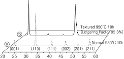
도 22는 비교 예와 실시 예의 압전 세라믹 소결체 즉, 비교 예의 압전 시편(ⓐ)과 실시 예의 압전 시편(ⓑ)의 표면 X선 회절 패턴들을 각각 나타내는 그래프이다. 본 그래프에서의 배향 정도는 로트게링 배향도(Lotgering factor)의 계산식에 따라 계산하였으며, 로트게링 배향도를 계산하는 계산식 및 구체적 과정에 대한 설명은 생략하기로 한다. 도 22에 도시된 바와 같이, 비교 예의 압전 시편(ⓐ)은 표면에서 모든 결정 방향으로 성장되었으며, 특히 (110) 평면의 법선 방향으로 결정이 두드러지게 성장하였음을 알 수 있다. 반면, 실시 예의 압전 시편(ⓑ)은 표면에서 (001) 평면의 법선 방향 및 동일한 방향을 가지는 (002) 평면의 법선 방향으로만 결정이 성장되어 있음을 알 수 있으며, 비교 예의 (110) 평면의 법선 방향으로는 결정 성장이 억제되어 있다. 또한, 본 그래프의 높이는 X선 피크의 강도를 나타내며, 각 X선 피크 강도로부터 실시 예의 압전 시편(ⓑ)의 경우 로트게링 배향도가 95.3%의 값을 가지는 것을 알 수 있었다. 이를 통하여 시드 조성물이 포함된 압전 세라믹 소결체는 (001) 방향으로 배향 성장되어 결정 배향성이 현저하게 향상되었음을 확인할 수 있다.22 is a graph showing the surface X-ray diffraction patterns of the piezoelectric ceramics of the comparative example and the piezoelectric ceramic specimen of the embodiment (b), respectively. The degree of orientation in this graph is calculated according to a calculation formula of Lotgering factor, and a calculation formula for calculating the Lotgering orientation degree and a detailed description thereof will be omitted. As shown in FIG. 22, the piezoelectric sample (a) of the comparative example was grown in all the crystal directions on the surface, and the crystal was prominently grown especially in the normal direction of the (110) plane. On the other hand, it can be seen that the piezoelectric specimen (b) of the embodiment is grown only in the normal direction of the (002) plane having the normal direction and the same direction of the (001) plane on the surface, Crystal growth is suppressed in the normal direction. The height of this graph represents the intensity of the X-ray peak. From the X-ray peak intensities of the graphs, it was found that the Lotgering orientation degree of the piezoelectric sample (b) of the Example had a value of 95.3%. As a result, the piezoelectric ceramics sintered body including the seed composition was grown in the (001) direction and the crystal orientation was remarkably improved.
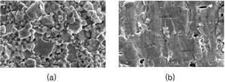
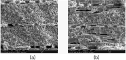
도 23은 압전 세라믹 소결체의 스캔 전자 현미경 이미지를 나타내는 이미지이다. 즉, 도 23의 (a)는 비교 예에 의하여 제조된 압전 시편의 단면 이미지이고, 도 23의 (b)는 실시 예에 의하여 제조된 압전 시편의 단면 이미지이다. 도 23의 (a)에 나타난 바와 같이, 시드 조성물이 첨가되지 않은 압전 세라믹 소결체의 경우 입자가 육각형의 형상으로 성장되었음을 알 수 있다. 이는 결정이 다수의 평면 방향으로 각각 성장하는 도 22의 결과와도 일치한다. 반면, 도 23의 (b)에 나타난 바와 같이 시드 조성물이 첨가된 압전 세라믹 소결체는 수평 위치된 시드 조성물(도 23의 (b)의 검은색 영역)에 의하여 사각형의 형상으로 성장되어 결정 배향성이 향상되었음을 확인할 수 있다.23 is an image showing a scanning electron microscope image of the piezoelectric ceramics sintered body. That is, FIG. 23A is a cross-sectional image of the piezoelectric specimen manufactured by the comparative example, and FIG. 23B is a cross-sectional image of the piezoelectric specimen manufactured by the embodiment. As shown in FIG. 23 (a), it can be seen that, in the case of the piezoelectric ceramics sintered body to which the seed composition was not added, the particles were grown in a hexagonal shape. This also coincides with the result of FIG. 22 in which crystals grow in a plurality of plane directions, respectively. On the other hand, as shown in FIG. 23 (b), the piezoelectric ceramics sintered body to which the seed composition is added grows in a quadrangular shape by the horizontally positioned seed composition (black region in FIG. 23B) .
또한, 도 24는 압전 세라믹 소결체를 압전층으로 이용한 압전 소자의 단면 이미지이다. 즉, 도 24의 (a)는 비교 예에 따른 압전 세라믹 소결체를 압전층으로 이용한 압전 소자의 단면 이미지이고, 도 24의 (b)는 실시 예에 따른 압전 세라믹 소결체를 압전층으로 이용한 압전 소자의 단면 이미지이다. 도 24의 (b)에 도시된 바와 같이 실시 예를 이용한 압전 소자는 시드 조성물(도 24의 (b)의 검은색 영역)이 존재하고, 도 24의 (a)에 도시된 바와 같이 비교 예를 이용한 압전 소자는 시드 조성물이 존재하지 않음을 알 수 있다. 이때, 시드는 1㎛∼20㎛의 길이 및 폭으로 배향된다. 즉, 시드의 배향 정도가 일 방향 및 이와는 다른 타 방향으로 각각 1㎛∼20㎛ 정도 배향될 수 있으며, 바람직하게는 6㎛∼20㎛ 정도 배향될 수 있다.24 is a cross-sectional image of a piezoelectric device using a piezoelectric ceramics sintered body as a piezoelectric layer. 24 (a) is a sectional view of a piezoelectric device using a piezoelectric ceramics sintered body according to a comparative example as a piezoelectric layer, and Fig. 24 (b) is a sectional view of the piezoelectric element using the piezoelectric ceramic sintered body according to the embodiment as a piezoelectric layer Sectional image. As shown in Fig. 24 (b), the piezoelectric element using the embodiment has the seed composition (the black region in Fig. 24 (b)) and the comparative example as shown in Fig. 24 (a) It can be seen that the piezoelectric element used does not have a seed composition. At this time, the seeds are oriented with a length and a width of 1 mu m to 20 mu m. That is, the degree of orientation of the seeds may be oriented in the order of 1 to 20 mu m in one direction and the other direction, respectively, and preferably 6 to 20 mu m or so.
시드 조성물이 첨가된 압전층을 이용하는 경우 시드 조성물이 첨가되지 않은 압전층을 이용하는 경우에 비해 압전 진동 부재의 진동력을 증가시킬 수 있다. 즉, 동일 사이즈를 갖는 압전 진동 부재에서 시드 조성물이 첨가된 압전층을 이용하면 진동력을 더 증가시켜 음압 특성을 향상시킬 수 있다.When the piezoelectric layer to which the seed composition is added is used, the vibration force of the piezoelectric vibrating member can be increased as compared with the case where the piezoelectric layer without the seed composition is used. That is, by using the piezoelectric layer to which the seed composition is added in the piezoelectric vibrating member having the same size, the vibration power can be further increased to improve the sound pressure characteristics.
압전 진동 부재의 실시 예들Embodiments of a piezoelectric vibrating member
도 25 내지 도 28은 본 발명의 일 실시 예들에 따른 압전 진동 부재의 단면도이다.25 to 28 are sectional views of a piezoelectric vibrating member according to one embodiment of the present invention.
도 25를 참조하면, 본 발명의 일 실시 예에 따른 압전 진동 부재(2000)는 모듈 케이스(2500)와, 모듈 케이스(2500) 내부에 마련된 압전 진동 부재를 포함할 수 있다. 압전 진동 부재는 지지 부재(2300)와, 지지 부재(2300) 상에 마련된 진동판(2200)과, 진동판(2200)의 적어도 일면 상에 마련된 압전 소자(2100)를 포함할 수 있다. 모듈 케이스(2500)는 압전 진동 부재(2000)의 진동을 증폭하며, 이러한 진동을 전자기기에 전달한다. 즉, 모듈 케이스(2500)는 압전 진동 부재(2000)의 진동을 증폭시켜 전자기기에 전달한다. 이러한 모듈 케이스(2500)는 내부에 공간이 마련된 대략 육면체 형상으로 형성될 수 있다. 즉, 모듈 케이스(2500)는 평면부(2510)와, 평면부(2510)의 외측으로부터 상측으로 연장된 수직부(2520)와, 수직부(2520)의 상측으로부터 외측으로 돌출된 돌출부(2530)을 포함할 수 있다. 평면부(2510)는 소정의 두께를 가질 수 있다. 이때, 평면부(2510)의 두께는 압전 진동 부재(2000)의 두께보다 두꺼울 수 있다. 예를 들어, 평면부(2510)의 두께는 압전 진동 부재(2000)의 두께보다 2배 내지 4배 두꺼울 수 있다. 또한, 수직부(2520)에 의해 압전 진동 부재(2000)가 수용되는 공간이 마련될 수 있다. 따라서, 수직부(2520)는 압전 진동 부재(2000)의 두께를 고려하여 이들 두께와 동일 높이로 형성될 수 있다. 그리고, 돌출부(2510)는 도 4에 도시된 바와 같이 압전 진동 부재(2000)가 프론트 케이스(1110)의 개구(10)에 삽입될 때 프론트 케이스(1110)에 압전 진동 부재(2000)가 지지되도록 한다. 이때, 돌출부(2510) 및 프론트 케이스(1110)의 외측면은 프론트 케이스(1110)에 접착제 등을 이용하여 접착 고정될 수 있다. 물론, 돌출부(2510)를 나사 결합하여 압전 진동 부재(2000)가 프론트 케이스(1110)에 고정될 수도 있다.Referring to FIG. 25, a
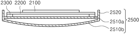
도 26에 도시된 바와 같이, 평면부(2510)는 상측 및 하측에 제 1 및 제 2 평면부(2510a, 2510b)가 마련되어 이들 사이에 내부에 공간이 마련될 수 있다. 즉, 제 1 및 제 2 평면부(2510a, 2510b)가 수직 방향으로 소정 간격 이격되고 그 외측에 수직부가 형성되어 제 1 및 제 2 평면부(2510a, 2510b) 사이에 소정의 공간이 형성될 수 있다. 이러한 공간은 압전 진동 부재(2000)에서 발생된 진동을 증폭하는 공명 공간으로 이용될 수 있다. 한편, 공간 내에는 이종의 물질이 매립될 수 있다. 예를 들어, 실리콘 등 압전 진동 부재(2000)와 모듈 케이스(2500)와 다른 물질이 공간 내에 마련될 수 있다. 이렇게 공간 내에 이종의 물질이 매립됨으로써 진동 특성을 조절할 수 있다.As shown in FIG. 26, first and second
도 27에 도시된 바와 같이, 평면부(2510)는 일면이 라운드하게 형성될 수 있다. 즉, 도 2에 도시된 바와 같이 일면이 라운드하게 형성되고, 해당 면이 프론트 케이스(1110)를 통해 디스플레이(200)와 접촉될 수 있다. 즉, 도 2에 도시된 바와 같은 형태로 프론트 케이스(1110)를 통해 디스플레이(200)에 선 접촉될 수 있다. As shown in FIG. 27, the
또한, 도 28에 도시된 바와 같이, 제 1 및 제 2 평면부(2510a, 2510b)가 수직 방향으로 이격되어 마련되어 모듈 케이스(2500) 내부에 소정의 공간이 마련될 수 있다. 또한, 제 1 및 제 2 평면부(2510a, 2510b) 사이의 공간 내에 이종의 물질이 매립될 수 있다.28, the first and second
도 29 내지 도 33은 본 발명의 또다른 실시 예들에 따른 압전 진동 부재의 단면도이다.29 to 33 are sectional views of a piezoelectric vibrating member according to still another embodiment of the present invention.
도 29에 도시된 바와 같이, 지지 부재(2300) 상에 진동판(2200)이 마련되고, 진동판(2200)의 일면 상에 압전 소자(2100)가 마련된다. 이때, 압전 소자(2100)는 지지 부재(2300)가 접촉된 진동판(2200)의 일면 상에 마련된다. 즉, 압전 소자(2100)와 지지 부재(2300)는 진동판(2200)의 동일 면 상에 마련된다. 여기서, 압전 소자(2100)는 지지 부재(2300)와 소정 간격 이격되어 지지 부재(2300)의 내측에 마련될 수 있다.29, a
도 30에 도시된 바와 같이, 지지 부재(2300)는 하측으로 연장 형성된 후 다시 수평 방향으로 연장 형성되어 진동판(2200)의 하측에 소정의 공간이 마련되도록 할 수 있다. 즉, 지지 부재(2300)는 일측이 개방된 대략 "ㄷ"자 형태로 마련될 수 있다. 이를 위해 지지 부재(2300)는 진동판(2200)의 가장자리로부터 하측으로 연장 형성된 수직부(2310)와, 수직부(2310)로부터 내측으로 연장 형성된 수평부(2320)를 포함하며, 수평부(2320)는 중앙부가 개방된 형태로 형성될 수 있다. 즉, 진동판(2200)의 하측에는 내부에 소정 공간이 마련되고 일측이 개방된 형태의 지지 부재(2300)가 마련될 수 있다. 이렇게 함으로써 압전 진동 부재(2000)의 진동을 증폭시키고, 증폭된 진동을 전자기기에 전달할 수 있다. 또한, 도 31에 도시된 바와 같이 진동판(2200)의 일면, 즉 내부 공간에는 웨이트 부재(2400)가 마련될 수 있다.As shown in FIG. 30, the
도 32를 참조하면, 압전 진동 부재(2000)를 덮도록 보강재(stiffener)(26000)가 더 마련될 수 있다. 즉, 지지 부재(2300)의 소정 영역이 소정 폭으로 제거된 후 그 영역에 접촉되어 대략 "ㄷ"자 형태의 보강재(2600)가 마련될 수 있다. 보강재(2600)는 압전 소자(2100) 및 진동판(2200)을 보호하고 강도를 보강하기 위해 마련될 수 있다. 이때, 보강재(2600)는 지지 부재(2300)와는 접촉되고 압전 소자(2100) 및 진동판(2200)과는 이격되어 마련될 수 있다. 따라서, 보강재(2600)의 내측으로 압전 진동 부재가 마련될 수 있다. 이러한 경우에도 진동판(2200)의 일면 상에 웨이트 부재가 더 마련될 수 있다.Referring to Fig. 32, a stiffener 26000 may be further provided to cover the piezoelectric vibrating
도 33을 참조하면, 지지 부재(2300)는 하측으로 연장 형성된 후 다시 수평 방향으로 연장 형성되어 진동판(2200)의 하측에 소정의 공간이 마련되도록 할 수 있다. 즉, 지지 부재(2300)는 내부 공간이 폐쇄되도록 대략 "ㄷ"자 형태로 마련될 수 있다. 이를 위해 지지 부재(2300)는 진동판(2200)의 가장자리로부터 하측으로 연장 형성된 수직부(2310)와, 수직부(2310)로부터 내측으로 연장 형성된 수평부(2330)를 포함하며, 수평부(2330)는 수직부(2310) 사이를 폐쇄하도록 형성될 수 있다. 즉, 진동판(2200)의 하측에는 내부에 소정 공간이 마련되고 폐쇄된 지지 부재(2300)가 마련될 수 있다.Referring to FIG. 33, the
한편, 본 발명의 일 실시 예들 및 다른 실시 예들에 따른 압전 진동 부재(2000)는 도 34에 도시된 바와 같이 전자기기에 장착될 수 있다. 즉, 도 34에 도시된 바와 같이, 전자기기는 윈도우(100)와, 윈도우(100) 일측에 마련된 디스플레이(200)와, 디스플레이(200) 일측에 마련된 프론트 케이스(1110)와, 프론트 케이스(1110)의 적어도 일부에 마련되는 압전 진동 부재(2000)를 포함할 수 있다. 또한, 프론트 케이스(1110)는 윈도우(100)의 가장자리를 지지하는 지지부(310)와, 디스플레이(200)의 하면과 이격되어 마련되며 일부가 지지부(310)와 연결되는 평판부(320)를 포함할 수 있는데, 압전 진동 부재(2000)는 지지부(310)의 적어도 일부에 형성될 수 있다. 즉, 압전 진동 부재(2000)가 마련되는 지지부(310)의 적어도 일부는 제거되고, 제거된 영역에 압전 진동 부재(2000)가 마련될 수 있다. 이때, 압전 진동 부재(2000)가 마련되지 않는 지지부(310)는 수직부와 수평부를 포함하여 이루어질 수 있고, 압전 진동 부재(2000)가 마련되는 영역의 지지부(310)는 수직부의 내측 및 수평부의 상측 적어도 일부가 제거될 수 있다.On the other hand, the
또한, 도 35에 도시된 바와 같이 디스플레이(200)와 프론트 케이스(1110) 사이에 간격 부재(600)가 마련되고, 지지 부재(600)의 소정 영역에 지지되도록 압전 진동 부재(2000)가 마련될 수 있다. 즉, 디스플레이(200)와 프론트 케이스(1110)의 평판부(320) 사이의 소정 영역에 간격 부재(600)가 마련되고, 간격 부재(600)는 내측으로 수평 방향으로 돌출된 지지 부재(2300)가 마련되며, 지지 부재(2300)에 지지되도록 압전 소자(2100) 및 진동판(2200)을 포함하는 압전 진동 부재(2000)가 마련될 수 있다. 여기서, 지지 부재(2300)는 간격 부재(600)와 일체로 마련될 수 있다. 즉, 간격 부재(600)로부터 돌출된 돌출부 상에 진동판(2200) 및 압전 소자(2100)가 마련될 수도 있다.35, a spacing
한편, 본 발명의 기술적 사상은 상기 실시 예에 따라 구체적으로 기술되었으나, 상기 실시 예는 그 설명을 위한 것이며, 그 제한을 위한 것이 아님을 주지해야 한다. 또한, 본 발명의 기술분야에서 당업자는 본 발명의 기술 사상의 범위 내에서 다양한 실시 예가 가능함을 이해할 수 있을 것이다.While the present invention has been particularly shown and described with reference to exemplary embodiments thereof, it is to be understood that the invention is not limited to the disclosed exemplary embodiments. It will be apparent to those skilled in the art that various modifications and variations can be made in the present invention without departing from the spirit and scope of the invention.
1000 : 전자기기
2000 : 압전 진동 부재
2100 : 압전 소자
2200 : 진동판
2300 : 지지 부재
2400 : 웨이트 부재1000: Electronic device 2000: Piezoelectric vibration member
2100: piezoelectric element 2200: diaphragm
2300: support member 2400: weight member
Claims (18)
상기 지지 부재 상에 마련된 진동판; 및
상기 진동판의 적어도 일면 상에 마련된 압전 소자를 포함하며,
상기 지지 부재는 경도가 5 내지 95인 압전 진동 장치.
A support member;
A diaphragm provided on the support member; And
And a piezoelectric element provided on at least one surface of the diaphragm,
Wherein the support member has a hardness of 5 to 95. < Desc / Clms Page number 24 >
The piezoelectric vibrating apparatus according to claim 1, wherein the hardness of the vibration plate is higher than or equal to the hardness of the support member.
The piezoelectric vibration device according to claim 1, wherein the support member supports at least a part of the edge of the diaphragm, and the piezoelectric element is provided inside the support members.
The piezoelectric vibrating apparatus according to claim 1, wherein the piezoelectric element includes a plurality of piezoelectric layers, a plurality of inner electrodes formed between the plurality of piezoelectric layers, and an outer electrode provided outside the plurality of inner electrodes.
The piezoelectric vibrating apparatus of claim 4, wherein the upper and lower piezoelectric layers of the internal electrode operate in opposite directions.
5. The piezoelectric vibrating apparatus according to claim 4, wherein the piezoelectric element further comprises a base, and the plurality of piezoelectric layers and the internal electrodes are formed on both sides of the base.
7. The piezoelectric vibrating apparatus of claim 6, wherein the base includes a non-polarized piezoelectric layer, and the upper and lower piezoelectric layers of the base operate in opposite directions.
The piezoelectric vibrating apparatus of claim 6, wherein the thickness of the base is 1/3 to 1/150 of the piezoelectric element thickness.
The piezoelectric vibrating apparatus according to claim 6, wherein the thickness of the piezoelectric layer is equal to or thicker than the thickness of the base or the internal electrode.
7. The piezoelectric vibrating apparatus of claim 6, wherein the thickness of each of the piezoelectric layers is 1/3 to 1/100 of the thickness of the piezoelectric element.
5. The piezoelectric vibrating apparatus according to claim 4, wherein the piezoelectric layer includes at least one pore.
5. The piezoelectric vibrating apparatus according to claim 4, wherein the thickness of at least one region of the internal electrode is different.
5. The piezoelectric vibrating device according to claim 4, wherein the internal electrode has an area of 10% to 97% of the piezoelectric layer area.
상기 디스플레이의 일측에 마련되며 사용자가 터치 가능한 윈도우;
상기 윈도우의 측면으로부터 상기 디스플레이의 타측에 마련된 케이스; 및
상기 케이스의 적어도 일 영역에 마련되며, 청구항 1 내지 청구항 14 중 적어도 한 항 기재의 압전 진동 장치를 포함하고,
상기 압전 진동 장치는 진동으로 인한 공기의 떨림을 통하여 소리를 발생시키거나, 골전도 방식으로 소리를 전달하는 전자기기.
A display for displaying an image;
A window provided on one side of the display, the window being accessible by a user;
A case provided on the other side of the display from a side of the window; And
The piezoelectric vibrating device according to any one of claims 1 to 14, which is provided in at least one region of the case,
The piezoelectric vibrating device generates sound through vibration of the air due to vibration or transmits sound in a bone conduction manner.
16. The electronic device according to claim 15, wherein the case includes a front case, a rear case and a cover case, and the piezoelectric vibrating device is provided in at least one region of at least one of the front case, the rear case and the cover case.
17. The electronic apparatus according to claim 16, comprising an opening or groove formed in at least one region of the front case, wherein at least a part of the piezoelectric vibrating device is inserted into the opening or the groove.
18. The electronic device according to claim 17, wherein the piezoelectric vibrating device is in contact with the display.
Priority Applications (2)
| Application Number | Priority Date | Filing Date | Title |
|---|---|---|---|
| PCT/KR2018/002008 WO2018155867A1 (en) | 2017-02-24 | 2018-02-19 | Piezoelectric vibration apparatus and electronic device comprising same |
| TW107106050A TW201838429A (en) | 2017-02-24 | 2018-02-23 | Piezoelectric vibrating device and electronic device having the same |
Applications Claiming Priority (2)
| Application Number | Priority Date | Filing Date | Title |
|---|---|---|---|
| KR1020170024971 | 2017-02-24 | ||
| KR20170024971 | 2017-02-24 |
Publications (1)
| Publication Number | Publication Date |
|---|---|
| KR20180098128A true KR20180098128A (en) | 2018-09-03 |
Family
ID=63600949
Family Applications (1)
| Application Number | Title | Priority Date | Filing Date |
|---|---|---|---|
| KR1020180002359A Ceased KR20180098128A (en) | 2017-02-24 | 2018-01-08 | Piezoelectric vibrating device and electronic device having the same |
Country Status (2)
| Country | Link |
|---|---|
| KR (1) | KR20180098128A (en) |
| TW (1) | TW201838429A (en) |
Cited By (5)
| Publication number | Priority date | Publication date | Assignee | Title |
|---|---|---|---|---|
| KR20200069602A (en) * | 2018-12-07 | 2020-06-17 | 엘지디스플레이 주식회사 | Display apparatus |
| WO2020158980A1 (en) * | 2019-02-01 | 2020-08-06 | 엘지전자 주식회사 | Mobile terminal |
| JP2021012369A (en) * | 2019-07-04 | 2021-02-04 | エルジー ディスプレイ カンパニー リミテッド | Display device |
| KR20210111654A (en) | 2020-03-03 | 2021-09-13 | 김보화 | Auxiliary Window for Air Conditioner Installation |
| WO2026024088A1 (en) * | 2024-07-25 | 2026-01-29 | 주식회사 아모센스 | Piezoelectric speaker |
Families Citing this family (4)
| Publication number | Priority date | Publication date | Assignee | Title |
|---|---|---|---|---|
| US11545612B2 (en) | 2019-05-03 | 2023-01-03 | May Sun Technology Co., Ltd. | Pseudo-piezoelectric D33 device and electronic device using the same |
| KR102472120B1 (en) | 2019-05-03 | 2022-11-28 | 메이 선 테크놀로지 씨오 엘티디 | Pseudo-Piezoelectric d33 Vibration Device and Display Integrating The Same |
| JP7661216B2 (en) * | 2020-12-31 | 2025-04-14 | エルジー ディスプレイ カンパニー リミテッド | Apparatus and vibration generating device |
| KR20230018953A (en) * | 2021-07-30 | 2023-02-07 | 엘지디스플레이 주식회사 | Vibration apparatus and apparatus comprising the same |
Citations (2)
| Publication number | Priority date | Publication date | Assignee | Title |
|---|---|---|---|---|
| JP3929465B2 (en) | 2002-09-03 | 2007-06-13 | シャープ株式会社 | Liquid crystal display device having voice output function and the like and electronic apparatus equipped with the same |
| KR20140074299A (en) | 2011-09-13 | 2014-06-17 | 케이디디아이 가부시키가이샤 | Communication device |
-
2018
- 2018-01-08 KR KR1020180002359A patent/KR20180098128A/en not_active Ceased
- 2018-02-23 TW TW107106050A patent/TW201838429A/en unknown
Patent Citations (2)
| Publication number | Priority date | Publication date | Assignee | Title |
|---|---|---|---|---|
| JP3929465B2 (en) | 2002-09-03 | 2007-06-13 | シャープ株式会社 | Liquid crystal display device having voice output function and the like and electronic apparatus equipped with the same |
| KR20140074299A (en) | 2011-09-13 | 2014-06-17 | 케이디디아이 가부시키가이샤 | Communication device |
Cited By (7)
| Publication number | Priority date | Publication date | Assignee | Title |
|---|---|---|---|---|
| KR20200069602A (en) * | 2018-12-07 | 2020-06-17 | 엘지디스플레이 주식회사 | Display apparatus |
| WO2020158980A1 (en) * | 2019-02-01 | 2020-08-06 | 엘지전자 주식회사 | Mobile terminal |
| JP2021012369A (en) * | 2019-07-04 | 2021-02-04 | エルジー ディスプレイ カンパニー リミテッド | Display device |
| US11675561B2 (en) | 2019-07-04 | 2023-06-13 | Lg Display Co., Ltd. | Display apparatus |
| US12019948B2 (en) | 2019-07-04 | 2024-06-25 | Lg Display Co., Ltd. | Display apparatus |
| KR20210111654A (en) | 2020-03-03 | 2021-09-13 | 김보화 | Auxiliary Window for Air Conditioner Installation |
| WO2026024088A1 (en) * | 2024-07-25 | 2026-01-29 | 주식회사 아모센스 | Piezoelectric speaker |
Also Published As
| Publication number | Publication date |
|---|---|
| TW201838429A (en) | 2018-10-16 |
Similar Documents
| Publication | Publication Date | Title |
|---|---|---|
| KR20180098128A (en) | Piezoelectric vibrating device and electronic device having the same | |
| US11722825B2 (en) | Vibration generating device and display apparatus including the same | |
| US20180324519A1 (en) | Sound output apparatus | |
| JP2018019065A (en) | Piezoelectric vibration device and electronic apparatus including the same | |
| US11750979B2 (en) | Display apparatus including a sound generating device | |
| US12323751B2 (en) | Display apparatus | |
| KR20120064984A (en) | Piezoelectric speaker | |
| JP7320592B2 (en) | Vibration generator and vehicle including the same | |
| KR20200020532A (en) | Speaker and display apparatus comprising the same | |
| KR102771063B1 (en) | Vibration generation device and display apparatus comprising the same | |
| WO2018155867A1 (en) | Piezoelectric vibration apparatus and electronic device comprising same | |
| KR100872164B1 (en) | Piezoelectric Electroacoustic Converter Using Piezoelectric Single Crystal | |
| KR100573733B1 (en) | Piezoelectric vibrator with asymmetric I-shaped elastic body and piezoelectric panel speaker using the same | |
| KR101877505B1 (en) | Piezoelectric vibrating module and electronic device having the same | |
| KR101367453B1 (en) | Flat pannel speaker having damper film | |
| CN116074711A (en) | equipment used to produce sound | |
| KR20210086027A (en) | Display apparatus | |
| WO2017213415A1 (en) | Sound output apparatus | |
| JP2023084093A (en) | Device | |
| KR20220151529A (en) | Apparatus | |
| KR20180120086A (en) | Sound wave generation apparatus |
Legal Events
| Date | Code | Title | Description |
|---|---|---|---|
| A201 | Request for examination | ||
| PA0109 | Patent application |
Patent event code: PA01091R01D Comment text: Patent Application Patent event date: 20180108 |
|
| PA0201 | Request for examination | ||
| E902 | Notification of reason for refusal | ||
| PE0902 | Notice of grounds for rejection |
Comment text: Notification of reason for refusal Patent event date: 20180719 Patent event code: PE09021S01D |
|
| PG1501 | Laying open of application | ||
| E90F | Notification of reason for final refusal | ||
| PE0902 | Notice of grounds for rejection |
Comment text: Final Notice of Reason for Refusal Patent event date: 20190111 Patent event code: PE09021S02D |
|
| E601 | Decision to refuse application | ||
| PE0601 | Decision on rejection of patent |
Patent event date: 20190715 Comment text: Decision to Refuse Application Patent event code: PE06012S01D Patent event date: 20190111 Comment text: Final Notice of Reason for Refusal Patent event code: PE06011S02I Patent event date: 20180719 Comment text: Notification of reason for refusal Patent event code: PE06011S01I |