KR20180098014A - Power supply apparatus comprising electromagnetic wave conversion circuit - Google Patents
Power supply apparatus comprising electromagnetic wave conversion circuit Download PDFInfo
- Publication number
- KR20180098014A KR20180098014A KR1020170024930A KR20170024930A KR20180098014A KR 20180098014 A KR20180098014 A KR 20180098014A KR 1020170024930 A KR1020170024930 A KR 1020170024930A KR 20170024930 A KR20170024930 A KR 20170024930A KR 20180098014 A KR20180098014 A KR 20180098014A
- Authority
- KR
- South Korea
- Prior art keywords
- diode
- power supply
- power
- unit
- cathode
- Prior art date
- Legal status (The legal status is an assumption and is not a legal conclusion. Google has not performed a legal analysis and makes no representation as to the accuracy of the status listed.)
- Granted
Links
Images


Classifications
-
- H—ELECTRICITY
- H02—GENERATION; CONVERSION OR DISTRIBUTION OF ELECTRIC POWER
- H02N—ELECTRIC MACHINES NOT OTHERWISE PROVIDED FOR
- H02N11/00—Generators or motors not provided for elsewhere; Alleged perpetua mobilia obtained by electric or magnetic means
- H02N11/002—Generators
-
- H—ELECTRICITY
- H02—GENERATION; CONVERSION OR DISTRIBUTION OF ELECTRIC POWER
- H02M—APPARATUS FOR CONVERSION BETWEEN AC AND AC, BETWEEN AC AND DC, OR BETWEEN DC AND DC, AND FOR USE WITH MAINS OR SIMILAR POWER SUPPLY SYSTEMS; CONVERSION OF DC OR AC INPUT POWER INTO SURGE OUTPUT POWER; CONTROL OR REGULATION THEREOF
- H02M7/00—Conversion of AC power input into DC power output; Conversion of DC power input into AC power output
- H02M7/02—Conversion of AC power input into DC power output without possibility of reversal
- H02M7/04—Conversion of AC power input into DC power output without possibility of reversal by static converters
- H02M7/06—Conversion of AC power input into DC power output without possibility of reversal by static converters using discharge tubes without control electrode or semiconductor devices without control electrode
Landscapes
- Engineering & Computer Science (AREA)
- Power Engineering (AREA)
- Rectifiers (AREA)
Abstract
전력 공급 장치가 제공된다. 상기 전력 공급 장치는, 전력 공급 단자로부터 전력을 전달받아, 전력 소모부로 필요 전력을 공급하는 전력 공급부, 상기 전력 소모부로부터 발생된 전자파를 변환하여 변환 전력을 생산하는 에너지 변환부 및 상기 변환 전력을 전달받는 출력 단자를 포함할 수 있다. A power supply is provided. The power supply apparatus includes a power supply unit that receives power from a power supply terminal and supplies power to the power consuming unit, an energy conversion unit that converts the electromagnetic wave generated from the power consuming unit to produce converted power, And may include an output terminal to be transmitted.
Description
본 발명은 전력 공급 장치에 관련된 것으로, 보다 상세하게는, 전자파 변환 회로를 갖는 전력 공급 장치에 관련된 것이다.The present invention relates to a power supply apparatus, and more particularly, to a power supply apparatus having an electromagnetic wave conversion circuit.
화석 연료의 고갈로 대체 에너지를 개발하기 위한 많은 연구들이 진행되고 있다. 현재 각광받는 대체 에너지로는 원자력 에너지, 태양광 에너지, 풍력 에너지 및 조력 에너지 등이 있다. 원자력 에너지의 경우 방사능 폐기물의 처리와 원자력 발전소의 건설에 막대한 비용이 소모되는 단점이 있으며, 태양광 에너지의 경우 발전 효율이 투자 비용에 못 미치고 있으며, 풍력/조력 에너지의 경우 발전소의 설치 가능한 장소가 한정적이라는 단점이 있다. Much research is underway to develop alternative energy sources due to depletion of fossil fuels. Currently, alternative energy sources include nuclear energy, solar energy, wind energy, and tidal energy. In the case of nuclear energy, there is a disadvantage that the treatment of radioactive waste and the construction of nuclear power plant are costly. In case of solar energy, the power generation efficiency is less than the investment cost. In case of wind / tidal energy, There is a disadvantage that it is limited.
이에 대한 대안으로, 특허 공개 공보 10-2011-0003455에서 개시된 것과 같이 전자파를 이용한 유도 발전기 등, TV, 컴퓨터 등 각종 전자 기기에서 발생하는 전자기파를 에너지원으로 활용하기 위한 연구가 활발히 진행되고 있다.As an alternative to this, studies have been actively conducted to utilize electromagnetic waves generated from various electronic devices such as TVs and computers, such as an induction generator using electromagnetic waves, as an energy source as disclosed in Patent Publication No. 10-2011-0003455.
본 발명이 해결하고자 하는 일 기술적 과제는, 에너지 변환 효율이 향상된 전자파 변환 회로를 갖는 전력 공급 장치를 제공하는 데 있다. An aspect of the present invention is to provide a power supply apparatus having an electromagnetic wave conversion circuit with improved energy conversion efficiency.
본 발명이 해결하고자 하는 다른 기술적 과제는, 제조 비용이 감소된 전자파 변환 회로를 갖는 전력 공급 장치를 제공하는 데 있다. It is another object of the present invention to provide a power supply device having an electromagnetic wave conversion circuit with reduced manufacturing cost.
본 발명이 해결하고자 하는 또 다른 기술적 과제는, 단순한 구조의 전자파 변환 회로를 갖는 전력 공급 장치를 제공하는 데 있다. It is another object of the present invention to provide a power supply device having an electromagnetic wave conversion circuit of a simple structure.
본 발명이 해결하고자 하는 기술적 과제는 상술된 것에 제한되지 않는다. The technical problem to be solved by the present invention is not limited to the above.
상기 기술적 과제를 해결하기 위해, 본 발명은 전자파 변환 회로를 갖는 전력 공급 장치를 제공한다. In order to solve the above technical problems, the present invention provides a power supply apparatus having an electromagnetic wave conversion circuit.
일 실시 예에 따르면, 상기 전자파 변환 회로를 갖는 전력 공급 장치는, 전력 공급 단자로부터 전력을 전달받아, 전력 소모부로 필요 전력을 공급하는 전력 공급부, 상기 전력 소모부 또는 상기 전력 공급부로부터 발생된 전자파를 변환하여 변환 전력을 생산하는 에너지 변환부, 및 상기 변환 전력을 전달받는 출력 단자를 포함할 수 있다. According to one embodiment, the power supply apparatus having the electromagnetic wave conversion circuit includes a power supply unit that receives power from the power supply terminal and supplies power to the power consumption unit, and a power supply unit that supplies the power from the power consumption unit or the power supply unit An energy conversion unit for converting the input power to produce converted power, and an output terminal for receiving the converted power.
일 실시 예에 따르면, 상기 전자파 변환 회로를 갖는 전력 공급 장치는, 상기 전력 공급 단자로부터 전력을 전달받아 보조 전력을 생산하는 보조 전력 공급부를 더 포함하되, 상기 출력 단자는 상기 변환 전력 외에, 상기 보조 전력을 더 공급받을 수 있다. According to an embodiment, the power supply apparatus having the electromagnetic wave conversion circuit further includes an auxiliary power supply unit for receiving power from the power supply terminal and producing auxiliary power, wherein the output terminal includes, in addition to the converted power, More power can be supplied.
일 실시 예에 따르면, 상기 전력 공급 단자는, 핫 라인(hot line), 중성 라인(neutral line) 및 접지 라인(ground line)를 포함하고, 상기 에너지 변환부는, 상기 전력 소모부로부터 발생된 전자파가 교류 전류로 변환되는 안테나부, 상기 교류 전류가 입력되는 제1 입력 노드, 상기 접지 라인과 연결된 캐소드를 갖는 제1-1 다이오드, 상기 제1 입력 노드와 연결된 캐소드를 갖는 제1-2 다이오드, 상기 제1 입력 노드와 연결된 애노드를 갖는 제1-3 다이오드, 및 상기 접지 라인과 연결된 애노드를 갖는 제1-4 다이오드를 포함하고, 상기 보조 전력 공급부는, 상기 핫 라인과 연결되어 외부 전류가 입력되는 제2 입력 노드, 상기 중성 라인과 연결된 캐소드를 갖는 제2-1 다이오드, 상기 제2 입력 노드와 연결된 캐소드를 갖는 제2-2 다이오드, 상기 제2 입력 노드와 연결된 애노드를 갖는 제2-3 다이오드, 및 상기 중성 라인과 연결된 애노드를 갖는 제2-4 다이오드를 포함할 수 있다. According to an embodiment, the power supply terminal includes a hot line, a neutral line, and a ground line, and the energy conversion unit converts the electromagnetic wave generated from the power consuming unit A first diode having a first input node to which the alternating current is inputted, a first diode having a cathode connected to the ground line, a first diode having a cathode connected to the first input node, A first-third diode having an anode connected to a first input node, and a first-fourth diode having an anode connected to the ground line, the auxiliary power supply being connected to the hot line, A second-1 diode having a second input node, a cathode coupled to the neutral line, a second-2 diode having a cathode coupled to the second input node, an anode coupled to the second input node, Which may include a first diode having 2-4 2-3 diode, and an anode coupled to the neutral line.
일 실시 예에 따르면, 상기 출력 단자는, 상기 제1-1 다이오드의 애노드 및 상기 제1-2 다이오드의 애노드, 그리고, 상기 제2-1 다이오드의 애노드 및 상기 제2-2 다이오드의 애노드와 연결되어, 정류된 상기 외부 전류 및 정류된 상기 교류 전류가 전달되는 제1 출력 단자, 및 상기 제1-3 다이오드의 캐소드 및 상기 제1-4 다이오드의 캐소드 그리고, 제2-3 다이오드의 캐소드 및 상기 제2-4 다이오드의 캐소드와 연결되어, 정류된 상기 외부 전류 및 정류된 상기 교류 전류가 전달되는 제2 출력 단자를 포함할 수 있다. According to one embodiment, the output terminal is connected to the anode of the first-first diode and the anode of the first-second diode, and the anode of the second-first diode and the anode of the second- A first output terminal to which the rectified external current and the rectified rectified current are transmitted, and a cathode of the first and third diodes and a cathode of the first and second diodes, And a second output terminal connected to the cathode of the second-4 < th > diode, through which the rectified external current and the rectified rectified current are transmitted.
일 실시 예에 따르면, 상기 전자파 변환 회로를 갖는 전력 공급 장치는, 상기 제1 입력 노드로 제공되는 상기 교류 전류를 제어하는 제1 스위치부, 및상기 제2 입력 노드로 제공되는 상기 외부 전류를 제어하는 제2 스위치부를 포함할 수 있다. According to one embodiment, the power supply apparatus having the electromagnetic wave conversion circuit may further include: a first switch section for controlling the alternating current provided to the first input node; and a second switch section for controlling the external current provided to the second input node And a second switch unit for switching the second switch unit.
본 발명의 실시 예에 따르면, 전력 소모부로 필요 전력을 공급하는 전력 공급부, 상기 전력 소모부 또는 상기 전력 공급부로부터 발생된 전자파를 변환하여 변환 전력을 생산하는 에너지 변환부, 및 상기 변환 전력을 전달받는 출력 단자를 포함하는 전자파 변환 회로를 갖는 전력 공급 장치가 제공된다. According to an embodiment of the present invention, there is provided an electric power conversion system comprising: a power supply unit for supplying power required by a power consuming unit; an energy conversion unit for converting electromagnetic waves generated from the power consuming unit or the power supply unit to produce converted power; There is provided a power supply apparatus having an electromagnetic wave conversion circuit including an output terminal.
상기 에너지 변환부는 전력 소모부로부터 발생된 전자파를 이용하여, 변환 전력을 생산하여, 에너지 소비 효율을 향상시킬 수 있다. The energy conversion unit may generate converted power using electromagnetic waves generated from the power consumption unit, thereby improving energy consumption efficiency.
또한, 상기 전자파 변환 회로를 갖는 전력 공급 장치는, 전력 공급 단자로부터 전력을 공급받아, 보조 전력을 생산하고, 상기 보조 전력을 상기 변환 전력과 함께 상기 출력 단자로 전달하는 보조 전력 공급부를 더 포함할 수 있다. 이에 따라, 상기 출력 단자에서 상기 변환 전력 및 상기 보조 전력이 더해진 출력 전력이 외부 전자 기기로 전달될 수 있다. 이로 인해, 상기 출력 전력이 노이즈로 인식되지 않고, 상기 외부 전자 기기의 구동 전력으로 사용될 수 있다. 이에 따라, 에너지 소비 효율이 향상된 친환경적인 고신뢰성의 전자 시스템이 제공될 수 있다.The power supply apparatus having the electromagnetic wave conversion circuit further includes an auxiliary power supply unit that receives power from the power supply terminal and produces auxiliary power and transfers the auxiliary power to the output terminal together with the converted power . Accordingly, the output power to which the converted power and the auxiliary power are added at the output terminal can be transmitted to the external electronic device. Therefore, the output power is not recognized as noise and can be used as driving power for the external electronic device. Accordingly, an environmentally friendly and highly reliable electronic system with improved energy consumption efficiency can be provided.
도 1은 본 발명의 제1 실시 예에 따른 전자파 변환 회로를 갖는 전력 공급 장치를 설명하기 위한 도면이다.
도 2은 본 발명의 제2 실시 예에 따른 전자파 변환 회로를 갖는 전력 공급 장치를 설명하기 위한 도면이다.
도 3은 본 발명의 제1 실시 예에 따른 전자파 변환 회로를 갖는 전력 공급 장치를 설명하기 위한 회로도이다.
도 4는 본 발명의 제1 실시 예의 변형 예에 따른 에너지 변환부를 갖는 전력 공급 장치를 설명하기 위한 회로도이다.
도 5는 본 발명의 제1 실시 예 및 제1 실시 예의 변형 예에 따른 전자파 변환 회로를 갖는 전력 공급 장치의 제1 정류부를 설명하기 위한 회로도이다.
도 6은 본 발명의 제1 실시 예 및 제1 실시 예의 변형 예에 따른 전자파 변환 회로를 갖는 전력 공급 장치의 제1 평활회로부를 설명하기 위한 회로도이다.
도 7은 본 발명의 제2 실시 예에 따른 에너지 변환부를 갖는 전력 공급 장치를 설명하기 위한 회로도이고, 도 8은 본 발명의 제2 실시 예의 변형 예에 따른 에너지 변환부를 갖는 전력 공급 장치를 설명하기 위한 회로도이다.
도 9는 본 발명의 제2 실시 예 및 제2 실시 예의 변형 예에 따른 전자파 변환 회로를 갖는 전력 공급 장치의 제2 정류부를 설명하기 위한 회로도이다.
도 10은 본 발명의 제2 실시 예 및 제2 실시 예의 변형 예에 따른 전자파 변환 회로를 갖는 전력 공급 장치의 제2 평활회로부를 설명하기 위한 회로도이다.
도 11은 본 발명의 제3 실시 예에 따른 전자파 변환 회로를 갖는 전력 공급 장치를 설명하기 위한 회로도이다.
도 12는 본 발명의 제3 실시 예에 따른 전자파 변환 회로를 갖는 전력 공급 장치의 제1 모드를 설명하기 위한 도면이다.
도 13은 본 발명의 제3 실시 예에 따른 전자파 변환 회로를 갖는 전력 공급 장치의 제2 모드를 설명하기 위한 도면이다.
도 14는 본 발명의 실시 예에 따른 전자파 변환 회로를 갖는 전력 공급 장치에 사용되는 접지부를 설명하기 위한 도면이다. 1 is a view for explaining a power supply apparatus having an electromagnetic wave conversion circuit according to the first embodiment of the present invention.
2 is a view for explaining a power supply apparatus having an electromagnetic wave conversion circuit according to a second embodiment of the present invention.
3 is a circuit diagram for explaining a power supply apparatus having an electromagnetic wave conversion circuit according to the first embodiment of the present invention.
4 is a circuit diagram for explaining a power supply apparatus having an energy conversion unit according to a modification of the first embodiment of the present invention.
5 is a circuit diagram for explaining a first rectification part of a power supply device having an electromagnetic wave conversion circuit according to a modification of the first embodiment and the first embodiment of the present invention.
6 is a circuit diagram for explaining a first smoothing circuit portion of a power supply device having an electromagnetic wave conversion circuit according to
FIG. 7 is a circuit diagram for explaining a power supply apparatus having an energy conversion unit according to a second embodiment of the present invention, and FIG. 8 illustrates a power supply apparatus having an energy conversion unit according to a modification of the second embodiment of the present invention ≪ / RTI >
9 is a circuit diagram for explaining a second rectification section of a power supply apparatus having an electromagnetic wave conversion circuit according to a modification of the second embodiment and the second embodiment of the present invention.
10 is a circuit diagram for explaining a second smoothing circuit portion of a power supply device having an electromagnetic wave conversion circuit according to a modification of the second embodiment and the second embodiment of the present invention.
11 is a circuit diagram for explaining a power supply apparatus having an electromagnetic wave conversion circuit according to a third embodiment of the present invention.
12 is a diagram for explaining a first mode of a power supply apparatus having an electromagnetic wave conversion circuit according to a third embodiment of the present invention.
13 is a diagram for explaining a second mode of the power supply apparatus having the electromagnetic wave conversion circuit according to the third embodiment of the present invention.
14 is a diagram for explaining a grounding part used in a power supply apparatus having an electromagnetic wave conversion circuit according to an embodiment of the present invention.
이하, 첨부된 도면들을 참조하여 본 발명의 바람직한 실시 예를 상세히 설명할 것이다. 그러나 본 발명의 기술적 사상은 여기서 설명되는 실시 예에 한정되지 않고 다른 형태로 구체화 될 수도 있다. 오히려, 여기서 소개되는 실시 예는 개시된 내용이 철저하고 완전해질 수 있도록 그리고 당업자에게 본 발명의 사상이 충분히 전달될 수 있도록 하기 위해 제공되는 것이다.Hereinafter, preferred embodiments of the present invention will be described in detail with reference to the accompanying drawings. However, the technical spirit of the present invention is not limited to the embodiments described herein but may be embodied in other forms. Rather, the embodiments disclosed herein are provided so that the disclosure can be thorough and complete, and will fully convey the scope of the invention to those skilled in the art.
본 명세서에서, 어떤 구성요소가 다른 구성요소 상에 있다고 언급되는 경우에 그것은 다른 구성요소 상에 직접 형성될 수 있거나 또는 그들 사이에 제 3의 구성요소가 개재될 수도 있다는 것을 의미한다. 또한, 도면들에 있어서, 막 및 영역들의 두께는 기술적 내용의 효과적인 설명을 위해 과장된 것이다. In this specification, when an element is referred to as being on another element, it may be directly formed on another element, or a third element may be interposed therebetween. Further, in the drawings, the thicknesses of the films and regions are exaggerated for an effective explanation of the technical content.
또한, 본 명세서의 다양한 실시 예 들에서 제1, 제2, 제3 등의 용어가 다양한 구성요소들을 기술하기 위해서 사용되었지만, 이들 구성요소들이 이 같은 용어들에 의해서 한정되어서는 안 된다. 이들 용어들은 단지 어느 구성요소를 다른 구성요소와 구별시키기 위해서 사용되었을 뿐이다. 따라서, 어느 한 실시 예에 제 1 구성요소로 언급된 것이 다른 실시 예에서는 제 2 구성요소로 언급될 수도 있다. 여기에 설명되고 예시되는 각 실시 예는 그것의 상보적인 실시 예도 포함한다. 또한, 본 명세서에서 '및/또는'은 전후에 나열한 구성요소들 중 적어도 하나를 포함하는 의미로 사용되었다.Also, while the terms first, second, third, etc. in the various embodiments of the present disclosure are used to describe various components, these components should not be limited by these terms. These terms have only been used to distinguish one component from another. Thus, what is referred to as a first component in any one embodiment may be referred to as a second component in another embodiment. Each embodiment described and exemplified herein also includes its complementary embodiment. Also, in this specification, 'and / or' are used to include at least one of the front and rear components.
명세서에서 단수의 표현은 문맥상 명백하게 다르게 뜻하지 않는 한 복수의 표현을 포함한다. 또한, "포함하다" 또는 "가지다" 등의 용어는 명세서상에 기재된 특징, 숫자, 단계, 구성요소 또는 이들을 조합한 것이 존재함을 지정하려는 것이지, 하나 또는 그 이상의 다른 특징이나 숫자, 단계, 구성요소 또는 이들을 조합한 것들의 존재 또는 부가 가능성을 배제하는 것으로 이해되어서는 안 된다. 또한, 본 명세서에서 "연결"은 복수의 구성 요소를 간접적으로 연결하는 것, 및 직접적으로 연결하는 것을 모두 포함하는 의미로 사용된다. The singular forms "a", "an", and "the" include plural referents unless the context clearly dictates otherwise. It is also to be understood that the terms such as " comprises "or" having "are intended to specify the presence of stated features, integers, Should not be understood to exclude the presence or addition of one or more other elements, elements, or combinations thereof. Also, in this specification, the term "connection " is used to include both indirectly connecting and directly connecting a plurality of components.
또한, 하기에서 본 발명을 설명함에 있어 관련된 공지 기능 또는 구성에 대한 구체적인 설명이 본 발명의 요지를 불필요하게 흐릴 수 있다고 판단되는 경우에는 그 상세한 설명은 생략할 것이다.In the following description of the present invention, a detailed description of known functions and configurations incorporated herein will be omitted when it may make the subject matter of the present invention rather unclear.
도 1은 본 발명의 제1 실시 예에 따른 전자파 변환 회로를 갖는 전력 공급 장치를 설명하기 위한 도면이다.1 is a view for explaining a power supply apparatus having an electromagnetic wave conversion circuit according to the first embodiment of the present invention.
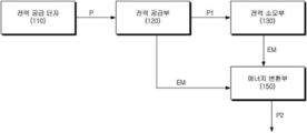
도 1을 참조하면, 본 발명의 실시 예에 따른 에너지 변환부를 갖는 전력 공급 장치는, 전력 공급 단자(110), 전력 공급부(120), 보조 전력 공급부(140), 및 에너지 변환부(150)를 포함할 수 있다. Referring to FIG. 1, a power supply apparatus having an energy conversion unit according to an embodiment of the present invention includes a
상기 전력 공급 단자(110)는, 상기 전력 공급부(120)로 전력(P)을 공급할 수 있다. 상기 전력 공급 단자(110)는, 교류 또는 직류 전원을 공급할 수 있다. 일 실시 예에 따르면, 상기 전력 공급 단자(110)는 콘센트일 수 있다. The
상기 전력 공급부(120)는, AC switched mode power supply 또는 DC switched mode power supply일 수 있다. 상기 전력 공급부(120)는, 상기 전력 공급 단자(110)로부터 상기 전력(P)을 공급받아, 전력 소모부(130)로 필요 전력(P1)을 전달할 수 있다. 상기 전력 공급부(120)가 상기 필요 전력(P1)을 생산하는 과정에서 전자파(EM)가 발생될 수 있다. The
일 실시 예에 따르면, 상기 전력 소모부(130)는 다양한 전자 제품(예를 들어, 온수 매트, 온열 매트, TV, PC, 냉장고 등)일 수 있다. 상기 전력 소모부(130)는 상기 전력 공급부(120)로부터 공급되는 상기 필요 전력(P1)에 의해 구동될 수 있다. 상기 전력 소모부(130)가 구동되는 과정에서 전자파(EM)가 발생될 수 있다. According to one embodiment, the power consuming unit 130 may be a variety of electronic products (e.g., a hot water mat, a warm mat, a TV, a PC, a refrigerator, etc.). The power consumption unit 130 may be driven by the required power P1 supplied from the
상기 에너지 변환부(130)는, 상기 전력 소모부(130) 또는 상기 전력 공급부(120)로부터 발생된 상기 전자파(EM)를 변환하여 변환 전력(P2)를 생성할 수 있다. 상기 전자파(EM)가 전도성 물체에 닿는 경우, 표면 전류가 생성될 수 있다. 상기 표면 전류는 교류 전류일 수 있다. 상기 표면 전류는 상기 전도성 물체의 표면을 따라 흐를 수 있다. 일 실시 예에 따르면, 상기 에너지 변환부(150)는 외부에서 방출되는 상기 전자파(EM)를 효율적으로 상기 교류 전류(표면 전류)로 변환하기 위해, 전도성 물질로 형성된 안테나를 구비할 수 있다.The energy conversion unit 130 may convert the electromagnetic wave EM generated from the power consumption unit 130 or the
상기 에너지 변환부(150)에서 생성된 상기 변환 전력(P2)이 출력 단자로 제공될 수 있다. 다시 말하면, 상기 출력 단자는 상기 변환 전력(P2)을 공급받아, 외부 전자 기기로 공급할 수 있다. 이에 따라, 에너지 소비 효율이 향상된 전력 공급 장치가 제공될 수 있다. The conversion power P2 generated by the
상술된 본 발명의 제1 실시 예와 달리, 본 발명의 제2 실시 예에 따르면, 전력 공급 단자로부터 전력을 공급받아 보조 전력을 생산하고, 상기 보조 전력을 상기 출력 단자로 공급하는 보조 전력 공급부가 더 제공될 수 있다. 이하, 도 2를 참조하면, 본 발명의 제2 실시 예에 따른 전자파 변환 회로를 갖는 전력 공급 장치가 설명된다. According to the second embodiment of the present invention, unlike the first embodiment of the present invention described above, the auxiliary power supply unit supplies power from the power supply terminal to produce auxiliary power, and supplies the auxiliary power to the output terminal Can be provided. Hereinafter, referring to Fig. 2, a power supply apparatus having an electromagnetic wave conversion circuit according to a second embodiment of the present invention will be described.
도 2은 본 발명의 제2 실시 예에 따른 전자파 변환 회로를 갖는 전력 공급 장치를 설명하기 위한 도면이다. 2 is a view for explaining a power supply apparatus having an electromagnetic wave conversion circuit according to a second embodiment of the present invention.
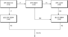
도 2를 참조하면, 본 발명의 제2 실시 예에 따른 에너지 변환부를 갖는 전력 공급 장치는, 전력 공급 단자(110), 전력 공급부(120), 보조 전력 공급부(140), 및 에너지 변환부(150)를 포함할 수 있다. Referring to FIG. 2, a power supply apparatus having an energy conversion unit according to a second embodiment of the present invention includes a
상기 전력 공급 단자(110), 상기 전력 공급부(120), 상기 에너지 변환부(150)는 도 1을 참조하여 설명된 것과 같이 제공될 수 있다. The
상기 보조 전력 공급부(140)는 상기 전력 공급 단자(110)로부터 상기 전력(P)을 전달받아, 보조 전력(P3)을 생성할 수 있다. The auxiliary
상기 보조 전력 공급부(140)에서 생성된 상기 보조 전력(P3) 및 상기 에너지 변환부(150)에서 생성된 상기 변환 전력(P2)이 더해져, 출력 단자로 제공될 수 있다. 다시 말하면, 상기 출력 단자는 상기 변환 전력(P2) 및 상기 보조 전력(P3)이 더해진 출력 전력을 공급받아, 외부 전자 기기로 상기 출력 전력을 공급할 수 있다. The auxiliary power P3 generated by the auxiliary
외부로 공급되는 상기 출력 전력의 값이 일정 기준보다 낮은 경우, 상기 출력 전력이 노이즈로 인식될 수 있다. 만약, 도 1을 참조하여 설명된 전자파 변환 회로를 갖는 전력 공급 장치에서, 상기 보조 전력(P3)이 공급되지 않고, 상기 변환 전력(P2)만이 상기 외부 전자 기기로 공급되는 경우, 상기 변환 전력(P2) 값이 상기 일정 기준보다 낮을 수 있고, 이에 따라 상기 변환 전력(P2)을 활용하는 것이 용이하지 않다. When the value of the output power supplied to the outside is lower than a certain reference, the output power may be recognized as noise. If the auxiliary power P3 is not supplied and only the converted power P2 is supplied to the external electronic apparatus in the power supply apparatus having the electromagnetic wave conversion circuit described with reference to Fig. 1, the converted power P2) may be lower than the predetermined reference value, and thus it is not easy to utilize the converted power P2.
하지만, 상술된 바와 같이, 본 발명의 실시 예에 따르면, 상기 출력 단자는, 상기 보조 전력 공급부(140)로부터 공급되는 상기 보조 전력(P3) 및 상기 전자파(EM)가 변환된 상기 변환 전력(P2)이 더해진 상기 출력 전력을 상기 외부 전자 기기로 공급할 수 있고, 이에 따라, 상기 변환 전력(P2)이 효율적으로 활용될 수 있다. However, as described above, according to the embodiment of the present invention, the output terminal is connected to the auxiliary power P3 supplied from the auxiliary
이하, 상술된 본 발명의 실시 예들에 따른 전자파 변환 회로를 갖는 전력 공급 장치의 구현 예가 설명된다. Hereinafter, an embodiment of a power supply apparatus having an electromagnetic wave conversion circuit according to the above-described embodiments of the present invention will be described.
도 3은 본 발명의 제1 실시 예에 따른 전자파 변환 회로를 갖는 전력 공급 장치를 설명하기 위한 회로도이고, 도 4는 본 발명의 제1 실시 예의 변형 예에 따른 에너지 변환부를 갖는 전력 공급 장치를 설명하기 위한 회로도이다.FIG. 3 is a circuit diagram for explaining a power supply apparatus having an electromagnetic wave conversion circuit according to the first embodiment of the present invention, and FIG. 4 is a diagram for explaining a power supply apparatus having an energy conversion unit according to a modification of the first embodiment of the present invention Fig.
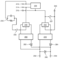
도 3 및 도 4를 참조하면, 본 발명의 실시 예에 따른 에너지 변환부를 갖는 전력 공급 장치는, 전력 공급 단자(212, 214, 216), 전력 공급부(220), 에너지 변환부(255, 250, 270, 284), 제1 스위치부(257), 제어 다이오드(286), 및 출력 단자(292, 294)를 포함할 수 있다. 3 and 4, a power supply apparatus having an energy conversion unit according to an embodiment of the present invention includes
상기 에너지 변환부(250, 255, 270, 284)는, 안테나부(255), 제1 정류부(250), 제1 평활 회로부(260), 및 제1 출력 다이오드(284)를 포함할 수 있다. The
상기 전력 공급 단자(212, 214, 216)는, AC 외부 전류가 공급되는 핫 라인(hot line, 212), 중성 라인(neutral line, 214), 및 접지 라인(ground line, 216)을 포함할 수 있다. The
상기 전력 공급부(220)는, 도 3에 도시된 바와 같이, 상기 접지 라인(216)과 연결되지 않는 AC switched mode power supply 또는 DC switched mode power supply일 수 있다. 또는, 상기 전력 공급부(220)는, 도 4에 도시된 바와 같이, 상기 접지 라인(216)과 연결된 AC switched mode power supply 또는 DC switched mode power supply일 수 있다.The
상기 안테나부(255)는 외부(전력 공급부(220) 또는 전력 소모부)에서 인가되는 전자파를 흡수하여, 교류 전류로 변환할 수 있다. 상기 교류 전류는 전자파가 전도성 물체(상기 안테나부(255))에 닿아 생성된 표면 전류일 수 있다. 상기 표면 전류는 상기 전도성 물체(상기 안테나부(255))의 표면을 따라 흐를 수 있다. 상기 안테나부(255)는 전도성 물질(예를 들어, 구리, 철, 퍼멀로이 등)로 형성된 판, 파이버, 메쉬, 상자형 등 다양한 형태로 구현될 수 있다. The
상기 제1 스위치부(257)는 상기 접지 라인(216)과 상기 안테나부(255)의 연결 여부를 제어할 수 있다. 상기 제1 스위치부(257)가 open되는 경우, 상기 안테나부(255)에서 생성된 상기 교류 전류는, 상기 제1 정류부(250)로 전달될 수 있다. 또는, 상기 제1 스위치부(257)가 closed 되는 경우, 상기 안테나부(255)에서 생성된 상기 교류 전류는 상기 접지 라인(216)에 의해 접지되어, 외부로 배출될 수 있다. The
상기 제1 정류부(250)는, 상기 안테나부(255)에서 생성된 상기 교류 전류를 정류할 수 있다. The
상기 제1 평활회로부(270)는, 상기 제1 정류부(250)에서 정류된 상기 교류 전류를 전달받아, 제1 직류 전류를 생산할 수 있다. The first
상기 제1 출력 다이오드(284)는 상기 제1 평활회로부(270)에서 생성된 상기 제1 직류 전류가 역전되는 것을 방지할 수 있고, 상기 제어 다이오드(286)는 제너 다이오드로 구성되어, 제1 출력 단자(292) 및 상기 제2 출력 단자(294) 사이에 배치될 수 있다. The
일 실시 예에 따르면, 제1 출력 단자(292) 및 상기 제2 출력 단자(294) 사이에 충전 커패시터가 배치될 수 있다. 이 경우, 상기 충전 커패시터를 이용하여, 스마트폰, 태블릿 PC, 비상 조명 스탠드 등 다양한 전자기기가 충전될 수 있다. According to one embodiment, a charge capacitor may be disposed between the
본 발명의 실시 예에 따르면, 상기 안테나부(255), 상기 제1 정류기(250), 및 상기 제1 평활 회로부(270)를 이용하여, 전력 소모부에서 발생된 전자파가 용이하게 흡수 및 차폐되어, 사용자에게 전자파가 전달되는 것이 최소화되는 것은 물론, 전자파를 이용하여 추가적인 전력이 생성될 수 있다. 이에 따라, 친환경적인 고효율의 전력 공급 장치가 제공될 수 있다. According to the embodiment of the present invention, the electromagnetic wave generated in the power consumption portion is easily absorbed and shielded by using the
일 변형 예에 따르면, 상기 제1 평활회로부(270), 제1 출력 다이오드(284), 및 상기 제어 다이오드(286) 중에서 적어도 어느 하나는 생략될 수 있다. According to one variant, at least one of the first
이하, 도 3 및 도 4를 참조하여 설명된 제1 정류부(250) 및 제1 평활회로부(270)의 구체적인 구성의 실시 예가 도 5 및 도 6을 참조하여 설명된다. Hereinafter, specific embodiments of the
도 5는 본 발명의 제1 실시 예 및 제1 실시 예의 변형 예에 따른 전자파 변환 회로를 갖는 전력 공급 장치의 제1 정류부를 설명하기 위한 회로도이다. 5 is a circuit diagram for explaining a first rectification part of a power supply device having an electromagnetic wave conversion circuit according to a modification of the first embodiment and the first embodiment of the present invention.
도 5를 참조하면, 상기 제1 정류부(250)는, 제1-1 다이오드(251) 내지 제1-4 다이오드(254)를 포함할 수 있다. Referring to FIG. 5, the
상기 안테나부(255)를 통해 상기 교류 전류가 입력되는 제1 입력 노드가 제공된다. A first input node through which the alternating current is inputted through the
상기 제1-1 다이오드(251)의 캐소드는, 상기 접지 라인(216, 도 4 참조)과 연결되고, 상기 제1-1 다이오드(251)의 애노드는 상기 제1 평활회로부(270)와 연결될 수 있다. The cathode of the first 1-1
상기 제1-2 다이오드(252)의 캐소드는 상기 제1 입력 노드와 연결되고, 상기 제1-2 다이오드(252)의 애노드는 상기 제1 평활회로부(270)와 연결될 수 있다. The cathode of the first-
상기 제1-3 다이오드(253)의 애노드는 상기 제1 입력 노드 및 상기 제1-2 다이오드(252)의 상기 캐소드와 연결되고, 상기 제1-3 다이오드(253)의 캐소드는 상기 제1 평활회로부(270)와 연결될 수 있다. The anode of the first-third diode (253) is connected to the first input node and the cathode of the first-second diode (252), and the cathode of the first-third diode (253) And may be connected to the
상기 제1-4 다이오드(254)의 애노드는 상기 접지 라인(216, 도 4 참조) 및 상기 제1-1 다이오드(251)의 상기 캐소드와 연결되고, 상기 제1-4 다이오드(254)의 캐소드는 상기 제1 평활회로부(270)와 연결될 수 있다. The anode of the first-
상기 제1-1 다이오드(251) 내지 상기 제1-4 다이오드(254)는, 상기 안테나부(255)를 통해 공급되는 교류 전류를 정류하여, 상기 제1 평활회로부(270)로 전달할 수 있다. The first 1-1
구체적으로, 상기 교류 전류 중 (+) 극성을 갖는 전류는 상기 제1-3 다이오드(253)를 통과하여 상기 제1 평활회로부(270)의 제1 노드로 전달되고, 상기 제1 평활회로부(270)에 (+) 극성을 갖는 전류가 저장되는 동안, 상기 제1-1 다이오드(251) 및 상기 접지 라인(216)은 상기 제2 평활회로부(270)의 제2 노드에 접지를 제공할 수 있다. Specifically, the AC current having positive polarity is passed through the first-
상기 교류 전류 중 (-) 극성을 갖는 전류는 상기 제1-2 다이오드(252)을 통과하여 상기 제1 평활회로부(270)의 제2 노드로 전달되고, 상기 제1 평활회로부(270)에 (-)극성을 갖는 전류가 저장되는 동안, 상기 제2-4 다이오드(254) 및 상기 접지(216)은 상기 제2 평활회로부(270)의 제2 노드에 접지를 제공할 수 있다. (-) polarity of the alternating current passes through the first-
다시 말하면, 상기 제1-1 내지 제1-4 다이오드들(251~254) 및 상기 접지 라인(216)은, 상기 교류 전류가 (+) 극성인 구간에서 상기 제1 평활회로부(270)의 제2 노드에 접지를 제공되고, 상기 교류 전류가 (-) 극성인 구간에서 상기 제1 평활회로부(270)의 제1 노드에 접지를 제공할 수 있다. In other words, the first to
다시 말하면, 상기 교류 전류의 극성에 따라서, 상기 제1 평활회로부(270) 와 연결된 노드들 중 어느 한 곳에 접지가 스위칭(switching)되어 제공될 수 있다. 구체적으로, 상기 교류 전류의 극성이 (+)인 구간에서, 상기 제1 평활회로부(270)의 상기 제2 노드에 접지가 제공되고, 상기 교류 전류의 극성이 (-)인 구간에서, 상기 제12 평활회로부(270)의 상기 제1 노드에 접지가 제공될 수 있다.In other words, depending on the polarity of the alternating current, the ground may be provided by being switched to any one of the nodes connected to the first
상기 제1 출력 단자(292)는, 상기 제1-1 다이오드(251)의 애노드 및 상기 제1-2 다이오드(252)의 애노드와 연결되어, 정류된 상기 교류 전류를 전달 받을 수 있다. The
또한, 상기 제2 출력 단자(294)는, 상기 제1-3 다이오드(253)의 캐소드 및 상기 제1-4 다이오드(254)의 캐소드와 연결되어, 정류된 상기 교류 전류를 전달 받을 수 있다. The
도 6은 본 발명의 제1 실시 예 및 제1 실시 예의 변형 예에 따른 전자파 변환 회로를 갖는 전력 공급 장치의 제1 평활회로부를 설명하기 위한 회로도이다.6 is a circuit diagram for explaining a first smoothing circuit portion of a power supply device having an electromagnetic wave conversion circuit according to
도 6을 참조하면, 상기 제1 평활회로부(270)는, 상기 제1 평활회로부(270)의 제1 노드 및 제2 노드와 연결된 제1 커패시터(271), 상기 제1 평활회로부(270)의 상기 제1 노드 및 제1 출력 다이오드(284)의 애노드를 연결하는 제1 인덕터(273), 상기 제1 평활회로부(260)의 상기 제2 노드와 연결되고 접지(274)를 제공받는 레귤레이터(272)를 포함할 수 있다. 6, the first
상기 제1 평활회로부(270)는, 상술된 바와 같이, 상기 제1 정류부(250)에서 정류된 상기 교류 전류를 이용하여, 상기 제1 직류 전류를 생성할 수 있다. The first
도 7은 본 발명의 제2 실시 예에 따른 에너지 변환부를 갖는 전력 공급 장치를 설명하기 위한 회로도이고, 도 8은 본 발명의 제2 실시 예의 변형 예에 따른 에너지 변환부를 갖는 전력 공급 장치를 설명하기 위한 회로도이다.FIG. 7 is a circuit diagram for explaining a power supply apparatus having an energy conversion unit according to a second embodiment of the present invention, and FIG. 8 illustrates a power supply apparatus having an energy conversion unit according to a modification of the second embodiment of the present invention ≪ / RTI >
도 7 및 도 8을 참조하면, 본 발명의 실시 예에 따른 전자파 변환 회로를 갖는 전력 공급 장치는, 도 3 내지 도 6을 참조하여 설명한 전력 공급 단자(212, 214, 216), 전력 공급부(220), 에너지 변환부(255, 250, 270, 284), 제1 스위치부(257), 제어 다이오드(286), 및 출력 단자(292, 294), 외에, 연결 저항부(230), 제2 스위치부(235), 보조 전력 공급부(240, 260, 282)를 더 포함할 수 있다. 7 and 8, a power supply apparatus having an electromagnetic wave conversion circuit according to an embodiment of the present invention includes
상기 전력 공급부(220)는, 도 7에 도시된 바와 같이, 상기 접지 라인(216)과 연결되지 않는 AC switched mode power supply 또는 DC switched mode power supply일 수 있다. 또는, 상기 전력 공급부(220)는, 도 8에 도시된 바와 같이, 상기 접지 라인(216)과 연결된 AC switched mode power supply 또는 DC switched mode power supply일 수 있다.The
상기 보조 전력 공급부(240, 260, 282)는, 제2 정류부(240), 제2 평활 회로부(260), 및 제2 출력 다이오드(282)를 포함할 수 있다. The auxiliary
상기 연결 저항부(230)는, 병렬 연결된 커패시터 및 저항을 포함하고, 상기 제2 스위치부(235)와 상기 핫 라인(232) 사이에 배치될 수 있다.The
상기 제2 스위치부(235)는, 상기 핫 라인(212)으로부터, 상기 연결 저항부(230)를 경유하여 제2 정류부(240)로 외부 전류 공급 여부를 제어할 수 있다.The
상기 제2 정류부(240)는, 상기 중성 라인(214)과 연결되고, 상기 제2 스위치부(235)와 연결되어, 상기 제2 스위치부(235)로부터 상기 외부 전류가 공급되는 경우, 상기 외부 전류를 정류하여, 상기 제2 평활회로부(260)로 전달할 수 있다. The
상기 제2 평활회로부(260)는 상기 제2 정류부(240)에서 정류된 상기 외부 전류를 전달받아, 제2 직류 전류를 생산할 수 있다. The second
상술된 바와 같이, 상기 제2 스위치부(235)는 외부 전류 공급 여부를 제어할 수 있다. 상기 안테나부(255)에서 흡수하는 전자파의 양이 충분하여, 교류 전류가 충분히 생성되는 경우, 상기 제2 스위치부(235)는 open되어, 상기 외부 전류가 공급되지 않을 수 있다. 또는, 상기 안테나부(255)에서 흡수하는 전자파의 양이 불충분하여, 상기 교류 전류가 충분히 생성되지 못하는 경우, 상기 제2 스위치부(235)는 closed되어, 상기 외부 전류가 공급될 수 있다. As described above, the
상기 제1 출력 다이오드(284) 및 상기 제2 출력 다이오드(282) 및 상기 제2 평활회로부(270) 및 상기 제1 평활회로부(260)에서 생성된 상기 제1 직류 전류 및 상기 제2 직류 전류가 역전되는 것을 방지할 수 있고, 상기 제어 다이오드(286)는 제너 다이오드로 구성되어, 제1 출력 단자(292) 및 상기 제2 출력 단자(294) 사이에 배치될 수 있다. The first direct current and the second direct current generated by the
일 실시 예에 따르면, 제1 출력 단자(292) 및 상기 제2 출력 단자(294) 사이에 충전 커패시터가 배치될 수 있다. 이 경우, 상기 충전 커패시터를 이용하여, 스마트폰, 태블릿 PC, 비상 조명 스탠드 등 다양한 전자기기가 충전될 수 있다. According to one embodiment, a charge capacitor may be disposed between the
이하, 도 7 및 도 8을 참조하여 설명된 상기 제2 정류부(240) 및 제2 평활회로부(260)의 구체적인 구성의 실시 예가 도 9 및 도 10을 참조하여 설명된다. Hereinafter, specific embodiments of the
도 9는 본 발명의 제2 실시 예 및 제2 실시 예의 변형 예에 따른 전자파 변환 회로를 갖는 전력 공급 장치의 제2 정류부를 설명하기 위한 회로도이다. 9 is a circuit diagram for explaining a second rectification section of a power supply apparatus having an electromagnetic wave conversion circuit according to a modification of the second embodiment and the second embodiment of the present invention.
도 9를 참조하면, 상기 제2 정류부(240)는, 제2-1 다이오드(241) 내지 제2-4 다이오드(244)를 포함할 수 있다. Referring to FIG. 9, the
상기 중성 라인(214)과 연결된 노드 및 상기 제2 스위치부(235)를 통해 상기 외부 전류가 입력되는 제2 입력 노드가 제공된다. A node connected to the
상기 제2-1 다이오드(241)의 캐소드는, 상기 중성 라인(214)과 연결되고, 상기 제2-1 다이오드(241)의 애노드는 상기 제2 평활회로부(260)와 연결될 수 있다. The cathode of the second-1
상기 제2-2 다이오드(242)의 캐소드는 상기 제2 입력 노드와 연결되고, 상기 제2-2 다이오드의 애노드는 상기 제2 평활회로부(260)와 연결될 수 있다. The cathode of the second 2-2
상기 제2-3 다이오드(243)의 애노드는 상기 제2 입력 노드 및 상기 제2-2 다이오드(242)의 상기 캐소드와 연결되고, 상기 제2-3 다이오드(243)의 캐소드는 상기 제2 평활회로부(260)와 연결될 수 있다. The anode of the second-third diode (243) is connected to the cathode of the second input node and the second-second diode (242), and the cathode of the second- And may be connected to the
상기 제2-4 다이오드(244)의 애노드는 상기 중성 라인(214) 및 상기 제2-1 다이오드(241)의 상기 캐소드와 연결되고, 상기 제2-4 다이오드(244)의 캐소드는 상기 제2 평활회로부(260)와 연결될 수 있다. The anode of the second 2-4
상기 제2-1 다이오드(241) 내지 상기 제2-4 다이오드(244)는, 상기 제2 스위치부(235)를 통해 공급되는 외부 전류(교류)를 정류하여, 상기 제2 평활회로부(260)로 전달할 수 있다. The second-1
구체적으로, 상기 외부 전류 중 (+) 극성을 갖는 전류는 상기 제2-3 다이오드(243)를 통과하여 상기 제2 평활회로부(260)의 제1 노드로 전달되고, 상기 제2 평활회로부(260)에 (+) 극성을 갖는 전류가 저장되는 동안, 상기 제2-1 다이오드(241) 및 상기 중성 라인(214)은 상기 제2 평활회로부(260)의 제2 노드에 접지를 제공할 수 있다. Specifically, a current having a positive polarity in the external current passes through the second-
상기 외부 전류 중 (-) 극성을 갖는 전류는 상기 제2-2 다이오드(242)을 통과하여 상기 제2 평활회로부(260)의 제2 노드로 전달되고, 상기 제2 평활회로부(260)에 (-)극성을 갖는 전류가 저장되는 동안, 상기 제2-4 다이오드(244) 및 상기 ground line(216)은 상기 제1 평활회로부(260)의 제1 노드에 접지를 제공할 수 있다. A current having a negative polarity in the external current passes through the second-
다시 말하면, 상기 제2-1 내지 제2-4 다이오드들(241~244) 및 상기 접지 라인(216)은, 상기 외부 전류가 (+) 극성인 구간에서 상기 제2 평활회로부(260)의 제2 노드에 접지를 제공되고, 상기 외부 전류가 (-) 극성인 구간에서 상기 제2 평활회로부(260)의 제1 노드에 접지를 제공할 수 있다. In other words, the 2-1 to 2-4
다시 말하면, 상기 외부 전류의 극성에 따라서, 상기 제2 평활회로부(260) 와 연결된 노드들 중 어느 한 곳에 접지가 스위칭(switching)되어 제공될 수 있다. 구체적으로, 상기 외부 전류의 극성이 (+)인 구간에서, 상기 제2 평활회로부(260)의 상기 제2 노드에 접지가 제공되고, 상기 외부 전류의 극성이 (-)인 구간에서, 상기 제2 평활회로부(260)의 상기 제1 노드에 접지가 제공될 수 있다.In other words, depending on the polarity of the external current, the ground may be provided by being switched to any one of the nodes connected to the second
상기 제1 출력 단자(292)는, 상기 제2-1 다이오드(241)의 애노드 및 상기 제2-2 다이오드(242)의 애노드와 연결되어, 정류된 상기 외부 전류를 전달 받을 수 있다. The
또한, 상기 제2 출력 단자(294)는, 상기 제2-3 다이오드(243)의 캐소드 및 상기 제2-4 다이오드(244)의 캐소드와 연결되어, 정류된 상기 외부 전류를 전달 받을 수 있다. The
또한, 도 7 내지 도 9를 참조하여 설명된 것과 같이, 상기 보조 전력 공급부(240, 260, 282)의 상기 제2 정류부(240)는 상기 핫 라인(212)으로부터 외부 전류를 공급받을 수 있다. 이에 따라, 상기 제1 정류부(250)의 상기 제1-1 다이오드(251)의 캐소드 및 상기 제1-4 다이오드(251)의 애노드가 상기 접지 라인(216)에 연결된 것과 달리, 상기 제2 정류부(240)의 상기 제2-1 다이오드(241)의 캐소드 및 상기 제2-4 다이오드(244)의 애노드는 상기 접지 라인(216)에 연결되지 않고, 상기 중성 라인(214)에 연결될 수 있다. 이에 따라, 누전 차단기가 작동하는 것이 방지될 수 있다. 7 to 9, the
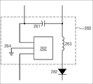
도 10은 본 발명의 제2 실시 예 및 제2 실시 예의 변형 예에 따른 전자파 변환 회로를 갖는 전력 공급 장치의 제2 평활회로부를 설명하기 위한 회로도이다.10 is a circuit diagram for explaining a second smoothing circuit portion of a power supply device having an electromagnetic wave conversion circuit according to a modification of the second embodiment and the second embodiment of the present invention.
도 10을 참조하면, 상기 제2 평활회로부(260)는, 상기 제2 평활회로부(260)의 제1 노드 및 제2 노드와 연결된 제2 커패시터(261), 상기 제2 평활회로부(260)의 상기 제1 노드 및 제2 출력 다이오드(282)의 애노드를 연결하는 제2 인덕터(263), 상기 제2 평활회로부(260)의 상기 제2 노드와 연결되고 접지(264)를 제공받는 레귤레이터(262)를 포함할 수 있다. 10, the second
상기 제2 평활회로부(260)는, 상술된 바와 같이, 상기 제2 정류부(240)에서 정류된 상기 외부 전류를 이용하여, 상기 제2 직류 전류를 생성할 수 있다The second
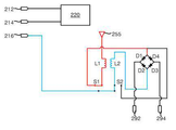
도 11은 본 발명의 제3 실시 예에 따른 전자파 변환 회로를 갖는 전력 공급 장치를 설명하기 위한 회로도이고, 도 12는 본 발명의 제3 실시 예에 따른 전자파 변환 회로를 갖는 전력 공급 장치의 제1 모드를 설명하기 위한 도면이고, 도 13은 본 발명의 제3 실시 예에 따른 전자파 변환 회로를 갖는 전력 공급 장치의 제2 모드를 설명하기 위한 도면이다. Fig. 11 is a circuit diagram for explaining a power supply apparatus having an electromagnetic wave conversion circuit according to a third embodiment of the present invention, and Fig. 12 is a circuit diagram of a first power supply apparatus having an electromagnetic wave conversion circuit according to the third embodiment of the present invention FIG. 13 is a view for explaining a second mode of the power supply apparatus having the electromagnetic wave conversion circuit according to the third embodiment of the present invention. FIG.
도 11을 참조하면, 실시 예 1 및 실시 예 2를 참조하여 설명된 전력 공급 단자(212, 214, 216), 전력 공급부(220), 안테나부(255)가 제공된다. Referring to Fig. 11,
상기 안테나부(255)와 연결된 제1 코일(L1) 및 상기 제2 코일(L2)을 포함하는 전력 변환부가 제공된다. A power conversion unit including a first coil L1 connected to the
상기 전력 변환부는 상기 안테나(255)를 통해 입력되는 교류 전류를 변환하여, 제1 내지 제4 다이오드(D1~D4)를 갖는 정류부로 전달할 수 있다. The power conversion unit may convert the alternating current inputted through the
상기 제1 다이오드(D1)의 애노드와 상기 제4 다이오드(D4)의 캐소드가 제1 노드로 정의될 수 있다. 또한, 상기 제2 다이오드(D2)의 애노드와 상기 제3 다이오드(D3)의 캐소드가 제2 노드로 정의될 수 있다. The anode of the first diode D1 and the cathode of the fourth diode D4 may be defined as a first node. Also, the anode of the second diode D2 and the cathode of the third diode D3 may be defined as a second node.
상기 제1 다이오드(D1)의 캐소드 및 상기 제2 다이오드(D2)의 캐소드가 제1 출력 단자(292)와 연결되고, 상기 제3 다이오드(D3)의 애노드 및 상기 제4 다이오드(D4)의 애노드가 제2 출력 단자(294)와 연결될 수 있다. The cathode of the first diode D1 and the cathode of the second diode D2 are connected to the
상기 정류부는 상기 제1 및 제2 출력 단자(292, 294)로 정류된 전류를 전달할 수 있다. The rectifying unit may deliver the rectified current to the first and
제1 스위치(S1)가 제공된다. 상기 제1 스위치(S1)는 상기 제1 코일(L1)과 상기 제1 노드의 연결 여부 및 상기 상기 제1 코일(L1)과 상기 접지 라인(216)의 연결 여부를 제어할 수 있다. A first switch S1 is provided. The first switch S1 may control whether or not the first coil L1 is connected to the first node and whether the first coil L1 and the
제2 스위치(S2)가 제공된다. 상기 제2 스위치(S2)는 상기 제2 코일(L2)과 상기 제1 노드의 연결 여부 및 상기 제2 코일(L2)과 상기 접지 라인(216)의 연결 여부를 제어할 수 있다. A second switch S2 is provided. The second switch S2 may control whether the second coil L2 is connected to the first node L2 and whether the second coil L2 is connected to the
보다 구체적으로, 제1 모드에서, 도 12에 도시된 바와 같이, 상기 제1 스위치(S1)는 상기 제1 코일(L1)과 상기 제1 노드를 연결하고, 상기 제2 스위치(S2)는 상기 제2 코일(L2)과 상기 접지 라인(216)을 연결할 수 있다. 이에 따라, 상기 안테나부(255)로부터 상기 제1 코일(L1)을 통과하여, 상기 제1 노드로 교류 전류가 입력될 수 있다. 또한, 상기 접지 라인(216)으로부터 상기 제2 코일을 통과하여, 상기 제2 노드로 접지가 제공될 수 있다. 이에 따라, 상기 제1 내지 제4 다이오드들(D1~D4)를 포함하는 상기 정류부에서 상기 교류 전류가 정류되고, 상기 출력 단자들(292, 294)로 공급될 수 있다. 12, the first switch S1 connects the first coil L1 to the first node, and the second switch S2 connects the first coil L1 to the first node L1, The second coil L2 and the
이와는 달리, 제2 모드에서, 도 13에 도시된 바와 같이, 상기 제1 스위치(S1)는 상기 제1 코일(L1)과 상기 접지 라인(216)을 연결할 수 있다. 이에 따라, 상기 안테나부(255)로부터 상기 제1 코일(L1)로 상기 교류 전류가 흐를 수 있고, 상기 제1 코일(L1)에 흐르는 상기 제1 교류 전류가 변환된 변환 전류(예를 들어, 전압이 강하된 전류)가 상기 제2 코일(L2)을 통과하여, 상기 제2 노드로 입력될 수 있다. 이에 따라, 상기 변환 전류가 상기 제1 내지 제4 다이오드들(D1~D4)를 포함하는 상기 정류부에서 상기 변환 저류가 정류되고, 상기 출력 단자들(292, 294)로 공급될 수 있다. Alternatively, in the second mode, the first switch S1 may connect the first coil L1 and the
도 14는 본 발명의 실시 예에 따른 전자파 변환 회로를 갖는 전력 공급 장치에 사용되는 접지부를 설명하기 위한 도면이다. 14 is a diagram for explaining a grounding part used in a power supply apparatus having an electromagnetic wave conversion circuit according to an embodiment of the present invention.
도 14를 참조하면, 상술된 바와 같이, 도 5를 참조하여 설명된 제1 정류부(250)의 제1-1 다이오드(251)의 캐소드 및 제1-4 다이오드(254)의 애노드에 접지 라인(216)이 연결되고, 도 12를 참조하여 설명된 정류부의 제2 다이오드(D2)의 애노드 및 제3 다이오드(D3)의 캐소드에 접지 라인(216)이 연결될 수 있다. 14, the cathode of the first-
이와 달리, 일 변형 예에 따르면, 도 14에 도시된 접지부에, 도 5를 참조하여 설명된 제1 정류부(250)의 제1-1 다이오드(251)의 캐소드 및 제1-4 다이오드(254)의 애노드가 연결되거나, 또는, 도 12를 참조하여 설명된 정류부의 제2 다이오드(D2)의 애노드 및 제3 다이오드(D3)의 캐소드가 연결될 수 있다. According to a variant, in the grounding portion shown in Fig. 14, the cathode of the first-
도 14에 도시된 접지부는, 평판부 및 상기 평판부로부터 돌출된 원뿔 형태의 돌출부를 포함할 수 있다. 상기 접지부는, 평판부의 넓은 표면적에 의해 전자가 지면으로 용이하게 빠져나갈 수 있다. 또한, 지면으로 빠져나가지 못한 전자들의 경우, 상기 돌출부의 뾰족한 일단에 모일 수 있고, 이 경우, 전압 반발력에 의해 대기 중으로 빠져나갈 수 있다. 이에 따라, 도 5를 참조하여 설명된 제1 정류부(250)의 제1-1 다이오드(251)의 캐소드 및 제1-4 다이오드(254)의 애노드, 또는 도 12를 참조하여 설명된 정류부의 제2 다이오드(D2)의 애노드 및 제3 다이오드(D3)의 캐소드에 효율적으로 접지가 제공될 수 있다. The ground portion shown in Fig. 14 may include a flat plate portion and a conical protrusion protruding from the flat plate portion. The ground portion can easily allow electrons to escape to the ground due to the large surface area of the flat plate portion. Further, in the case of electrons that can not escape to the ground, they can be collected at a sharp end of the protrusion, and in this case, they can escape to the atmosphere by the voltage repelling force. Accordingly, the cathode of the first-
일 실시 예에 따르면, 상기 접지부는, 구리, 알루미늄 등으로 형성될 수 있다. According to one embodiment, the ground portion may be formed of copper, aluminum, or the like.
또는, 상술된 바와 달리, 상기 접지부는 전선의 뭉치, 봉, 파이프 등 다양한 형태로 제공될 수 있다.Alternatively, unlike the above, the ground portion may be provided in various forms such as a bundle of wires, rods, pipes, and the like.
이상, 본 발명을 바람직한 실시 예를 사용하여 상세히 설명하였으나, 본 발명의 범위는 특정 실시 예에 한정되는 것은 아니며, 첨부된 특허청구범위에 의하여 해석되어야 할 것이다. 또한, 이 기술분야에서 통상의 지식을 습득한 자라면, 본 발명의 범위에서 벗어나지 않으면서도 많은 수정과 변형이 가능함을 이해하여야 할 것이다.While the present invention has been particularly shown and described with reference to exemplary embodiments thereof, it is to be understood that the scope of the present invention is not limited to the disclosed exemplary embodiments. It will also be appreciated that many modifications and variations will be apparent to those skilled in the art without departing from the scope of the present invention.
110: 전력 공급 단자
120, 220: 전력 공급부
130: 전력 소모부
140: 보조 전력 공급부
150: 에너지 변환부
230: 연결 저항부
235: 제1 스위치부
240: 제1 정류부
250: 제2 정류부
260: 제1 평활회로부
270: 제2 평활회로부
282, 284, 286: 제1 내지 제3 출력 다이오드
292, 294: 제1 및 제2 출력 단자110: Power supply terminal
120, 220: Power supply
130: power consumption unit
140: Auxiliary power supply
150: energy conversion unit
230: connection resistance portion
235: first switch section
240: first rectification part
250: second rectification part
260: first smoothing circuit portion
270: second smoothing circuit portion
282, 284, 286: first to third output diodes
292, 294: first and second output terminals
Claims (5)
상기 전력 소모부 또는 상기 전력 공급부로부터 발생된 전자파를 변환하여 변환 전력을 생산하는 에너지 변환부; 및
상기 변환 전력을 전달받는 출력 단자를 포함하는 전자파 변환 회로를 갖는 전력 공급 장치.
A power supply unit that receives power from the power supply terminal and supplies power to the power consuming unit;
An energy conversion unit for converting the electromagnetic waves generated from the power consumption unit or the power supply unit to produce converted power; And
And an output terminal for receiving the converted power.
상기 전력 공급 단자로부터 전력을 전달받아 보조 전력을 생산하는 보조 전력 공급부를 더 포함하되,
상기 출력 단자는 상기 변환 전력 외에, 상기 보조 전력을 더 공급받는 것을 포함하는 전력 공급 장치.
The method according to claim 1,
And an auxiliary power supply unit for receiving power from the power supply terminal and producing an auxiliary power,
And the output terminal further comprises a power supply for supplying the auxiliary power in addition to the converted power.
상기 전력 공급 단자는, 핫 라인(hot line), 중성 라인(neutral line) 및 접지 라인(ground line)를 포함하고,
상기 에너지 변환부는,
상기 전력 소모부로부터 발생된 전자파가 교류 전류로 변환되는 안테나부;
상기 교류 전류가 입력되는 제1 입력 노드;
상기 접지 라인과 연결된 캐소드를 갖는 제1-1 다이오드;
상기 제1 입력 노드와 연결된 캐소드를 갖는 제1-2 다이오드;
상기 제1 입력 노드와 연결된 애노드를 갖는 제1-3 다이오드; 및
상기 접지 라인과 연결된 애노드를 갖는 제1-4 다이오드를 포함하고,
상기 보조 전력 공급부는,
상기 핫 라인과 연결되어 외부 전류가 입력되는 제2 입력 노드;
상기 중성 라인과 연결된 캐소드를 갖는 제2-1 다이오드;
상기 제2 입력 노드와 연결된 캐소드를 갖는 제2-2 다이오드;
상기 제2 입력 노드와 연결된 애노드를 갖는 제2-3 다이오드; 및
상기 중성 라인과 연결된 애노드를 갖는 제2-4 다이오드를 포함하고,
하는 전자파 변환 회로를 갖는 전력 공급 장치.
3. The method of claim 2,
The power supply terminal includes a hot line, a neutral line, and a ground line,
Wherein the energy conversion unit comprises:
An antenna unit for converting an electromagnetic wave generated from the power consuming unit into an alternating current;
A first input node to which the alternating current is input;
A 1-1 diode having a cathode connected to the ground line;
A first-second diode having a cathode connected to the first input node;
A first-third diode having an anode connected to the first input node; And
And a fourth diode having an anode connected to the ground line,
Wherein the auxiliary power supply unit includes:
A second input node connected to the hot line to receive an external current;
A second-1 diode having a cathode connected to the neutral line;
A second 2-2 diode having a cathode coupled to the second input node;
A second-third diode having an anode connected to the second input node; And
And a second 2-4 diode having an anode connected to the neutral line,
Wherein the electromagnetic wave conversion circuit comprises:
상기 출력 단자는,
상기 제1-1 다이오드의 애노드 및 상기 제1-2 다이오드의 애노드, 그리고, 상기 제2-1 다이오드의 애노드 및 상기 제2-2 다이오드의 애노드와 연결되어, 정류된 상기 외부 전류 및 정류된 상기 교류 전류가 전달되는 제1 출력 단자; 및
상기 제1-3 다이오드의 캐소드 및 상기 제1-4 다이오드의 캐소드 그리고, 제2-3 다이오드의 캐소드 및 상기 제2-4 다이오드의 캐소드와 연결되어, 정류된 상기 외부 전류 및 정류된 상기 교류 전류가 전달되는 제2 출력 단자를 포함하는 전자파 변환 회로를 갖는 전력 공급 장치.
The method of claim 3,
The output terminal
An anode of the first 1-1 diode and an anode of the first 1-2 diode, and an anode of the second 2-1 diode and an anode of the second 2-2 diode, and the rectified external current and the rectified A first output terminal to which an alternating current is transmitted; And
A cathode of the first and third diodes and a cathode of the first and fourth diodes, and a cathode of the second and third diodes, and a cathode of the second and fourth diodes, and the rectified external current and the rectified alternating current And a second output terminal to which the second output terminal is connected.
상기 제1 입력 노드로 제공되는 상기 교류 전류를 제어하는 제1 스위치부; 및
상기 제2 입력 노드로 제공되는 상기 외부 전류를 제어하는 제2 스위치부를 포함하는 전자파 변환 회로를 갖는 전력 공급 장치.The method of claim 3,
A first switch for controlling the alternating current provided to the first input node; And
And a second switch section for controlling the external current supplied to the second input node.
Priority Applications (1)
| Application Number | Priority Date | Filing Date | Title |
|---|---|---|---|
| KR1020170024930A KR101983971B1 (en) | 2017-02-24 | 2017-02-24 | Power supply apparatus comprising electromagnetic wave conversion circuit |
Applications Claiming Priority (1)
| Application Number | Priority Date | Filing Date | Title |
|---|---|---|---|
| KR1020170024930A KR101983971B1 (en) | 2017-02-24 | 2017-02-24 | Power supply apparatus comprising electromagnetic wave conversion circuit |
Publications (2)
| Publication Number | Publication Date |
|---|---|
| KR20180098014A true KR20180098014A (en) | 2018-09-03 |
| KR101983971B1 KR101983971B1 (en) | 2019-09-03 |
Family
ID=63600834
Family Applications (1)
| Application Number | Title | Priority Date | Filing Date |
|---|---|---|---|
| KR1020170024930A Active KR101983971B1 (en) | 2017-02-24 | 2017-02-24 | Power supply apparatus comprising electromagnetic wave conversion circuit |
Country Status (1)
| Country | Link |
|---|---|
| KR (1) | KR101983971B1 (en) |
Citations (4)
| Publication number | Priority date | Publication date | Assignee | Title |
|---|---|---|---|---|
| JPH1189095A (en) * | 1997-07-17 | 1999-03-30 | N Ii T Kk | Power saving method and power saving associated system using the same |
| KR101541328B1 (en) * | 2014-11-28 | 2015-08-04 | 주식회사 디에스피 | A hot water mat with electro-magnetic wave absorption circuit and method of Electromagnetic wave absorption thereof |
| KR20150096862A (en) * | 2014-02-17 | 2015-08-26 | 주식회사 이엠코어 | Electromagnetic Wave Energy Conversion and Storage Device |
| JP2016105698A (en) * | 2016-03-10 | 2016-06-09 | 京セラ株式会社 | Power conditioner, control method, and display device |
-
2017
- 2017-02-24 KR KR1020170024930A patent/KR101983971B1/en active Active
Patent Citations (4)
| Publication number | Priority date | Publication date | Assignee | Title |
|---|---|---|---|---|
| JPH1189095A (en) * | 1997-07-17 | 1999-03-30 | N Ii T Kk | Power saving method and power saving associated system using the same |
| KR20150096862A (en) * | 2014-02-17 | 2015-08-26 | 주식회사 이엠코어 | Electromagnetic Wave Energy Conversion and Storage Device |
| KR101541328B1 (en) * | 2014-11-28 | 2015-08-04 | 주식회사 디에스피 | A hot water mat with electro-magnetic wave absorption circuit and method of Electromagnetic wave absorption thereof |
| JP2016105698A (en) * | 2016-03-10 | 2016-06-09 | 京セラ株式会社 | Power conditioner, control method, and display device |
Also Published As
| Publication number | Publication date |
|---|---|
| KR101983971B1 (en) | 2019-09-03 |
Similar Documents
| Publication | Publication Date | Title |
|---|---|---|
| US9425703B2 (en) | AC/DC converter circuit for common three-phase AC input voltages and method of operating such converter circuit | |
| RU2701510C1 (en) | Configuration of converter for electric charging station and corresponding electric charging station | |
| JP6089282B2 (en) | Power converter | |
| CN105099234B (en) | Magnetic field energy collecting device | |
| CN108258780A (en) | A kind of ultra-high-tension power transmission line electrical equipment wireless power supply system | |
| CN103762726B (en) | A kind of domestic solar wireless power supply system | |
| WO2011092302A2 (en) | Electric energy grid connecting system and electric energy transmission system and method | |
| CN110165773A (en) | Uninterruptible power system based on wisdom street lamp | |
| CN106532779B (en) | A solar grid-connected power generation system and control method thereof | |
| KR101022760B1 (en) | Wireless electromagnetic wave generation system | |
| Jhunjhunwala et al. | Technological and deployment challenges and user-response to uninterrupted DC (UDC) deployment in Indian homes | |
| CN102593878A (en) | Mobile vehicle charging device with alternating current and direct current charging functions | |
| KR101983971B1 (en) | Power supply apparatus comprising electromagnetic wave conversion circuit | |
| CN101976107B (en) | Zero standby power consumption computer power supply | |
| CN104269843B (en) | Photovoltaic air conditioner power supply circuit and photovoltaic air conditioner | |
| KR101383975B1 (en) | Electromagnetic wave energy conversion and storage device | |
| CN106787766B (en) | Circuit of reversed excitation and electronic device | |
| CN106160022A (en) | Direct-current multi-voltage power transmission and distribution system | |
| CN201490911U (en) | Power-saving power supply device with battery module | |
| KR101733315B1 (en) | Energy harvesting system using multi-tap transformer | |
| KR101894320B1 (en) | Energy harvesting system using multi-tap transformer | |
| CN207968088U (en) | A kind of contactless electrical energy transmission system | |
| KR101929617B1 (en) | Electronic system comprising an energy convertor, and the method of operating the same | |
| US20170012479A1 (en) | Energy conversion and storage apparatus using electronic wave | |
| KR101233785B1 (en) | Adc power supply system |
Legal Events
| Date | Code | Title | Description |
|---|---|---|---|
| A201 | Request for examination | ||
| PA0109 | Patent application |
Patent event code: PA01091R01D Comment text: Patent Application Patent event date: 20170224 |
|
| PA0201 | Request for examination | ||
| E902 | Notification of reason for refusal | ||
| PE0902 | Notice of grounds for rejection |
Comment text: Notification of reason for refusal Patent event date: 20180111 Patent event code: PE09021S01D |
|
| AMND | Amendment | ||
| E902 | Notification of reason for refusal | ||
| PE0902 | Notice of grounds for rejection |
Comment text: Notification of reason for refusal Patent event date: 20180720 Patent event code: PE09021S01D |
|
| PG1501 | Laying open of application | ||
| AMND | Amendment | ||
| E601 | Decision to refuse application | ||
| PE0601 | Decision on rejection of patent |
Patent event date: 20190321 Comment text: Decision to Refuse Application Patent event code: PE06012S01D Patent event date: 20180720 Comment text: Notification of reason for refusal Patent event code: PE06011S01I Patent event date: 20180111 Comment text: Notification of reason for refusal Patent event code: PE06011S01I |
|
| AMND | Amendment | ||
| PX0901 | Re-examination |
Patent event code: PX09011S01I Patent event date: 20190321 Comment text: Decision to Refuse Application Patent event code: PX09012R01I Patent event date: 20181120 Comment text: Amendment to Specification, etc. Patent event code: PX09012R01I Patent event date: 20180313 Comment text: Amendment to Specification, etc. |
|
| PX0701 | Decision of registration after re-examination |
Patent event date: 20190520 Comment text: Decision to Grant Registration Patent event code: PX07013S01D Patent event date: 20190422 Comment text: Amendment to Specification, etc. Patent event code: PX07012R01I Patent event date: 20190321 Comment text: Decision to Refuse Application Patent event code: PX07011S01I Patent event date: 20181120 Comment text: Amendment to Specification, etc. Patent event code: PX07012R01I Patent event date: 20180313 Comment text: Amendment to Specification, etc. Patent event code: PX07012R01I |
|
| X701 | Decision to grant (after re-examination) | ||
| PR0701 | Registration of establishment |
Comment text: Registration of Establishment Patent event date: 20190524 Patent event code: PR07011E01D |
|
| PR1002 | Payment of registration fee |
Payment date: 20190524 End annual number: 3 Start annual number: 1 |
|
| PG1601 | Publication of registration | ||
| PR1001 | Payment of annual fee |
Payment date: 20220321 Start annual number: 4 End annual number: 4 |
|
| PR1001 | Payment of annual fee |
Payment date: 20230306 Start annual number: 5 End annual number: 5 |
|
| PR1001 | Payment of annual fee |
Payment date: 20240305 Start annual number: 6 End annual number: 6 |