KR20180098005A - Visual acuity measurement apparatus - Google Patents
Visual acuity measurement apparatus Download PDFInfo
- Publication number
- KR20180098005A KR20180098005A KR1020170024911A KR20170024911A KR20180098005A KR 20180098005 A KR20180098005 A KR 20180098005A KR 1020170024911 A KR1020170024911 A KR 1020170024911A KR 20170024911 A KR20170024911 A KR 20170024911A KR 20180098005 A KR20180098005 A KR 20180098005A
- Authority
- KR
- South Korea
- Prior art keywords
- unit
- lens
- eyepiece
- subject
- chart
- Prior art date
- Legal status (The legal status is an assumption and is not a legal conclusion. Google has not performed a legal analysis and makes no representation as to the accuracy of the status listed.)
- Withdrawn
Links
Images


Classifications
-
- A—HUMAN NECESSITIES
- A61—MEDICAL OR VETERINARY SCIENCE; HYGIENE
- A61B—DIAGNOSIS; SURGERY; IDENTIFICATION
- A61B3/00—Apparatus for testing the eyes; Instruments for examining the eyes
- A61B3/02—Subjective types, i.e. testing apparatus requiring the active assistance of the patient
- A61B3/028—Subjective types, i.e. testing apparatus requiring the active assistance of the patient for testing visual acuity; for determination of refraction, e.g. phoropters
- A61B3/0285—Phoropters
-
- A—HUMAN NECESSITIES
- A61—MEDICAL OR VETERINARY SCIENCE; HYGIENE
- A61B—DIAGNOSIS; SURGERY; IDENTIFICATION
- A61B3/00—Apparatus for testing the eyes; Instruments for examining the eyes
- A61B3/02—Subjective types, i.e. testing apparatus requiring the active assistance of the patient
- A61B3/028—Subjective types, i.e. testing apparatus requiring the active assistance of the patient for testing visual acuity; for determination of refraction, e.g. phoropters
- A61B3/04—Trial frames; Sets of lenses for use therewith
Landscapes
- Life Sciences & Earth Sciences (AREA)
- Health & Medical Sciences (AREA)
- Medical Informatics (AREA)
- Biophysics (AREA)
- Ophthalmology & Optometry (AREA)
- Engineering & Computer Science (AREA)
- Biomedical Technology (AREA)
- Heart & Thoracic Surgery (AREA)
- Physics & Mathematics (AREA)
- Molecular Biology (AREA)
- Surgery (AREA)
- Animal Behavior & Ethology (AREA)
- General Health & Medical Sciences (AREA)
- Public Health (AREA)
- Veterinary Medicine (AREA)
- Eye Examination Apparatus (AREA)
Abstract
본 발명은, 시력검사장치에 관한 것으로서, 보다 상세하게는 피검안자의 동체시력을 검사하는 시력검사장치에 관한 것이다.
본 발명은, 피검안자의 동체시력을 검사하는 시력검사장치(10)로서, 측정용 이미지(110)가 표시되는 차트부(100)와; 상기 차트부(100)에 표시된 측정용 이미지(110)를 접안부(310)를 통하여 피검안자가 관찰할 수 있도록 광경로를 형성하도록, 상기 차트부(100) 및 상기 접안부(310) 사이에 설치되는 복수의 렌즈들을 포함하는 렌즈부(200)와; 피검안자에 의하여 관찰되는 측정용 이미지(110)의 인식크기 및 측정용 이미지(110)에 대한 인식거리 중 적어도 하나를 변화시키기 위하여 상기 차트부(100) 및 상기 렌즈부(200) 중 적어도 하나를 상기 광경로(L)를 따라서 이동시키는 이동수단(400)을 포함하는 것을 특징으로 하는 시력검사장치(10)를 개시한다.BACKGROUND OF THE INVENTION 1. Field of the Invention The present invention relates to a visual acuity test apparatus, and more particularly, to a visual acuity test apparatus for inspecting a visual acuity of a subject's body.
The present invention provides a visual acuity examination apparatus (10) for inspecting a visual acuity of a fuselage of a subject, comprising: a chart unit (100) displaying a measurement image (110); And is provided between the chart unit 100 and the eyepiece unit 310 so as to form an optical path so that the subject can observe the measurement image 110 displayed on the chart unit 100 through the eyepiece unit 310 A lens unit 200 including a plurality of lenses; At least one of the chart unit 100 and the lens unit 200 is changed to change at least one of the recognition size of the measurement image 110 observed by the subject to be examined and the recognition distance to the measurement image 110 And moving means (400) for moving the optical path (L) along the optical path (L).
Description
본 발명은, 시력검사장치에 관한 것으로서, 보다 상세하게는 피검안자의 동체시력을 검사하는 시력검사장치에 관한 것이다.BACKGROUND OF THE INVENTION 1. Field of the Invention The present invention relates to a visual acuity test apparatus, and more particularly, to a visual acuity test apparatus for inspecting a visual acuity of a subject's body.
일반적으로 피검안자의 시력을 검사하는 장치는 피검안자의 눈에 측정용 광을 조사하고 피검안자의 각막에 의하여 반사된 광을 촬영한 후 촬영된 이미지를 분석하여 시력이나 눈의 상태를 검사(타각식)하거나, 일정한 측정용 이미지의 윤곽이 명확해지거나 희미해지는 지점(또는 거리, 초점 등)을 검사(자각식)하는 방식을 사용한다.In general, the apparatus for examining the visual acuity of an object to be examined irradiates light for measurement to the eye of the subject and radiates light reflected by the cornea of the subject and analyzes the photographed image to check the visual acuity or eye condition Or the point (or distance, focus, etc.) at which the outline of a certain measurement image becomes clear or blurred is inspected (subjective).
상술한 종래의 방식은 피검안자의 정지시력을 검사할 수 있을 뿐 움직이는 물체(동체), 즉 동적인 측정용 이미지에 대한 동체시력을 검사할 수 없고, 피검안자의 동체시력을 검사하기 위해서는 피검안자에게 모션이 형성된 측정용 이미지의 이미지를 제공하는 수단이 제시되어야 한다.In the conventional method described above, it is impossible to inspect the visual acuity of the moving object (the moving body), that is, the dynamic image for measurement, while only the visual acuity of the subject can be inspected. To examine the visual acuity of the subject's fuselage, A means for providing an image of the measurement image in which the motion is formed should be presented.
한편, 움직임이 따른 사물에 대한 정확한 반응을 요하는 야구나 복싱과 같은 스포츠 분야에서 동체시력은 매우 중요한 신체능력으로서 피검안자의 동체시력을 검사하는 것이 중요한데, 종래의 동체시력검사장치의 경우, 피검안자에게 인식되는 측정용 이미지의 동적모션을 실제적인 것으로 느껴지도록 하는 기술적 방안을 제시하지 못해 효과적인 동체시력을 검사할 수 없는 문제점이 있다.On the other hand, in sports such as baseball or boxing, which require precise response to moving objects, it is important to examine the fuselage visual acuity of the subject to be examined as a very important physical ability of the fuselage visual acuity. There is a problem in that it is not possible to propose a technical solution to make the dynamic motion of the image for measurement recognized by the Anja feel realistic, and thus the effective visualization of the fuselage can not be performed.
본 발명의 목적은 상기와 같은 추세 및 필요성을 인식하여, 움직이는 물체에 대한 시력, 즉 동체시력을 효과적으로 검사할 수 있는 시력검사장치를 제공하는 데 있다.SUMMARY OF THE INVENTION It is an object of the present invention to provide a visual inspection apparatus capable of effectively inspecting a visual acuity of a moving object, that is, a visual sense of a moving body, by recognizing the above trend and necessity.
본 발명은 상기와 같은 본 발명의 목적을 달성하기 위하여 창출된 것으로서, 본 발명은, 피검안자의 동체시력을 검사하는 시력검사장치(10)로서, 측정용 이미지(110)가 표시되는 차트부(100)와; 상기 차트부(100)에 표시된 측정용 이미지(110)를 접안부(310)를 통하여 피검안자가 관찰할 수 있도록 광경로를 형성하도록, 상기 차트부(100) 및 상기 접안부(310) 사이에 설치되는 복수의 렌즈들을 포함하는 렌즈부(200)와; 피검안자에 의하여 관찰되는 측정용 이미지(110)의 인식크기 및 측정용 이미지(110)에 대한 인식거리 중 적어도 하나를 변화시키기 위하여 상기 차트부(100) 및 상기 렌즈부(200) 중 적어도 하나를 상기 광경로(L)를 따라서 이동시키는 이동수단(400)을 포함하는 것을 특징으로 하는 시력검사장치(10)를 개시한다.In order to achieve the above object, the present invention provides a visual acuity check apparatus (10) for inspecting a visual acuity of a subject's fuselage, comprising a chart unit 100); And is provided between the
상기 차트부(100)는, 전기신호에 의하여 상기 측정용 이미지(110)를 디스플레이하는 디스플레이부를 포함할 수 있다.The
상기 렌즈부(200)는, 상기 차트부(100)로부터 상기 접안부(310)까지 상기 광경로를 따라서 순차적으로 배치된 제1발산렌즈(210), 제2발산렌즈(220) 및 수렴렌즈(230)를 포함할 수 있다.The
본 발명에 따른 시력검사장치는, 상기 제1발산렌즈(210), 상기 제2발산렌즈(220) 및 상기 수렴렌즈(230)가 이루는 간격들 중 적어도 하나의 간격을 조절하기 위하여 상기 제1발산렌즈(210), 상기 제2발산렌즈(220) 및 상기 수렴렌즈(230) 중 적어도 하나를 이동시키는 렌즈간격조절수단을 포함할 수 있다.The eye dioptric power of the first diverging
상기 접안부(310)는, 피검안자의 한 쌍의 안구에 대응되어 한 쌍으로 설치되며, 상기 렌즈부(200)의 광경로를 상기 한 쌍의 접안부(310)에 대응되어 2개의 접안광경로(L1, L2)들로 분할하는 광경로분할부(600)를 추가로 포함할 수 있다.The
본 발명에 따른 시력검사장치는, 피검안자의 한 쌍의 안구 사이의 거리에 대응되어 상기 한 쌍의 접안부(310) 사이의 간격을 조절하기 위한 접안조절부재(320)가 추가로 설치될 수 있다.The eye sight testing apparatus according to the present invention may further include a
본 발명에 따른 시력검사장치는, 상기 광경로분할부(600)에 의하여 분할된 접안광경로(L1, L2)들 중 어느 하나의 광경로를 차단하는 광차단부가 추가로 설치될 수 있다.The visual acuity test apparatus according to the present invention may further include a light intercepting unit for intercepting any one of the eyepiece optical paths L1 and L2 divided by the light
상기 이동수단(400)은, 상기 차트부(100) 및 상기 렌즈부(200) 중 적어도 하나의 선형이동을 구동하는 모터와, 상기 차트부(100) 및 상기 렌즈부(200) 중 적어도 하나의 선형이동을 가이드하는 가이드부를 포함할 수 있다.The moving
상기 렌즈부(200)는, 복수의 렌즈들이 이루는 간격이 유지된 상태로 이동될 수 있다.The
본 발명에 따른 시력검사장치는, 상기 차트부(100)와 상기 렌즈부(200) 사이, 및 상기 렌즈부(200) 및 상기 접안부(310) 중 적어도 하나에 설치되어 광경로를 변환시키는 하나 이상의 광경로변환부(500)를 추가로 포함할 수 있다.The visual acuity test apparatus according to the present invention may be provided with at least one of the
본 발명에 따른 시력검사장치는, 피검안자의 동체시력 측정시 측정용 이미지가 표시되는 차트부 및 렌즈부 중 적어도 하나를 광경로를 따라서 이동시키는 이동수단을 포함함으로써, 피검안자에 의하여 관찰되는 측정용 이미지의 인식크기 및 측정용 이미지에 대한 인식거리 중 적어도 하나를 변화시킬 수 있어, 피검안자가 측정용 이미지가 실제로 움직이는 것으로 인식시킬 수 있어 동체시력을 효율적으로 측정할 수 있는 이점이 있다.The visual acuity test apparatus according to the present invention includes moving means for moving at least one of the chart portion and the lens portion along the optical path in which the measurement image is displayed in the measurement of the visual acuity of the fuselage of the subject, It is possible to change at least one of the recognition size of the image for measurement and the recognition distance of the measurement image so that the subject can recognize that the measurement image is actually moving so that it is possible to efficiently measure the visual acuity of the body.
특히, 본 발명에 따른 시력검사장치는, 하나 이상의 발산렌즈와 하나 이상의 수렴렌즈의 조합하여 차트부로부터 접안부에 이르는 광경로를 형성함으로써 차트부를 광경로를 따라서 크게 이동시키지 않더라도 피검안자에 의하여 관찰되는 측정용 이미지의 인식크기 및 측정용 이미지에 대한 인식거리 중 적어도 하나를 상대적으로 크게 변화시킬 수 있어 피검안자에 대한 동체시력의 검사를 효과적으로 수행할 수 있는 이점이 있다.Particularly, the visual acuity test apparatus according to the present invention is characterized in that, by combining at least one diverging lens and at least one converging lens to form an optical path from the chart portion to the eyepiece portion, even if the chart portion is not moved largely along the optical path, At least one of the recognition size of the image for measurement and the recognition distance of the image for measurement can be changed to a relatively large value, thereby effectively performing the examination of the visual acuity of the subject with respect to the subject.
또한, 본 발명에 따른 시력검사장치는, 전기신호에 의하여 화면을 구성하는 디스플레이장치, 즉 LCD패널, OLED패널 등 소위 평면패널을 이용하여 측정용 이미지를 표시함으로써, 피검안자에 대한 동체시력의 측정을 위한 측정용 이미지를 다양하게 변화시킬 수 있어 동체시력의 검사를 효과적으로 수행할 수 있는 이점이 있다.Also, the visual acuity test apparatus according to the present invention displays a measurement image using a so-called flat panel such as a display device constituting a screen by an electric signal, that is, an LCD panel, an OLED panel, It is advantageous to perform inspection of the visual acuity of the fuselage effectively.
예를 들면, 디스플레이장치 상에 표시되는 측정용 이미지에 대하여 형상, 색상 등의 속성변화, 애니메이션 효과 등을 부여함으로써 피검안자에 대한 다양한 형식 및 기준의 동체시력을 측정할 수 있다.For example, it is possible to measure the visual acuity of the fuselage of various types and standards with respect to the subject by giving an attribute change such as a shape, a color, and the like to the measurement image displayed on the display device.
더 나아가, 디스플레이장치 상에 표시되는 측정용 이미지에 대하여 형상, 색상 등의 속성변화, 애니메이션 효과 등의 부여가 가능하여, 미리 설정된 형상이 형성된 차트판을 포함하는 것보다 필요에 따라 차트판이나 측정용 이미지가 자체를 교체하지 않고도 측정용 이미지에 대한 다양한 변경이 가능한 이점이 있다.Furthermore, it is possible to apply a property change such as a shape and a color, an animation effect, and the like to a measurement image displayed on the display device, There is an advantage that various changes can be made to the image for measurement without replacing the image for itself.
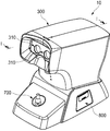
도 1은, 본 발명에 따른 시력검사장치를 보여주는 사시도이다.
도 2는, 도 1의 Ⅰ-Ⅰ 방향 단면도이다.
도 3은, 도 1의 시력검사장치의 구성을 보여주는 모식도이다.
도 4는, 도 3의 시력검사장치의 구성 일부를 보여주는 도면이다.
도 5a 및 도 5b는, 본 발명에 따른 시력검사장치의 동작을 보여주는 개념도이다.
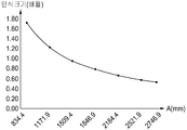
도 6은, 본 발명에 따른 시력검사장치에서 접안부와 측정용 이미지 사이의 거리-측정용 이미지의 이미지배율 사이의 관계를 설명하는 그래프이다.
도 7은, 도 1의 시력검사장치의 정면도이다.1 is a perspective view showing a vision test apparatus according to the present invention.
Fig. 2 is a cross-sectional view taken along the line I-I in Fig.
Fig. 3 is a schematic diagram showing the configuration of the visual acuity test apparatus of Fig. 1;
Fig. 4 is a view showing a part of the configuration of the visual acuity test apparatus of Fig. 3;
5A and 5B are conceptual diagrams showing the operation of the visual acuity test apparatus according to the present invention.
6 is a graph for explaining the relationship between the distance between the eyepiece and the measurement image in the visual acuity test apparatus according to the present invention, and the image magnification of the measurement image.
Fig. 7 is a front view of the visual acuity test apparatus of Fig. 1; Fig.
이하 본 발명에 따른 시력검사장치에 관하여 첨부된 도면을 참조하여 설명하면 다음과 같다.Hereinafter, a visual acuity test apparatus according to the present invention will be described with reference to the accompanying drawings.
본 발명에 따른 시력검사장치(10)는, 도 1 내지 도 6에 도시된 바와 같이, 피검안자의 동체시력을 검사하는 시력검사장치(10)로서, 측정용 이미지(110)가 표시되는 차트부(100)와; 차트부(100)에 표시된 측정용 이미지(110)를 접안부(310)를 통하여 피검안자가 관찰할 수 있도록 광경로를 형성하도록, 차트부(100) 및 접안부(310) 사이에 설치되는 복수의 렌즈들을 포함하는 렌즈부(200)와; 피검안자에 의하여 관찰되는 측정용 이미지(110)의 인식크기 및 측정용 이미지(110)에 대한 인식거리 중 적어도 하나를 변화시키기 위하여 차트부(100) 및 렌즈부(200) 중 적어도 하나를 광경로(L)를 따라서 이동시키는 이동수단(400)을을 포함한다.1 to 6, the visual
본 발명에 따른 시력검사장치(10)는, 피검안자에게 검안을 위한 특정이미지를 제공하여 피검안자의 시력을 측정하는 구성으로 다양한 구성이 가능하다.The visual
본 발명에 따른 시력검사장치(10)는, 작동모드에 따라 정지시력 및 동체시력 중 적어도 하나를 측정할 수 있다.The visual
여기서 정지시력이란, 피검안자에게 크기, 모양, 위치 등이 정지된 정적상태의 이미지를 제공하였을 때 측정되는 시력을 의미한다.Here, the term " still visual acuity " means the visual acuity measured when a static image of a size, shape, position,
동체시력이란, 움직이는 물체를 정확하고 빠르게 인지하는 능력으로 정의되며, 일반적으로 논하는 시력과는 다르게 움직이는 물체를 빠르고 정확하게 본다는 의미를 가진다고 보면 된다. 정지시력인 멀리까지 보는 것과는 차이가 있다. The visual acuity of a fuselage is defined as the ability to recognize a moving object accurately and quickly, and it is said that it means to see a moving object quickly and accurately, unlike the sight generally discussed. It is different from seeing far away sight.
이러한 동체시력의 측정을 위해서는, 피검안자에게 물체의 이동을 구현하기 위하여 측정용 이미지(110)의 크기, 모양, 위치 등이 변하는 동적상태의 이미지를 제공하여한다.In order to measure the visual acuity of the fuselage, an image of a dynamic state in which the size, shape, and position of the
보다 구체적으로 피검안자가 움직이는 이미지를 인식하는 능력을 동체시력으로 정의되며, 본 발명에 따른 시력검자장치(10)는, 움직이는 이미지의 구현을 위하여 측정용 이미지(110)를 눈을 통하여 인식할 때 크기, 위치 등이 변하도록 구성된다.More specifically, the ability of the subject to recognize the moving image is defined as a fusiform visual acuity, and the
상기 차트부(100)는, 피검안자에게 눈을 통하여 제공되는 이미지, 즉 측정용 이미지(110)가 표시되는 구성으로 다양한 구성이 가능하다.The
여기서, 상기 측정용 이미지(110)는, 그림, 문자, 색상 등으로 이루어지며, 동체시력 측정을 위하여 빠르게 이동되는 이동 이미지, 애니메이션, 크기가 변하는 이미지 등 다양하게 형성될 수 있다.Here, the
상기 차트부(100)는, 측정용 이미지(110)가 표시되는 구성으로서, 전기신호에 의하여 화면을 구성하는 디스플레이장치, 즉 LCD패널, OLED패널 등 소위 평면패널 등을 포함할 수 있다.The
상기 측정용 이미지(110)는 차트부(100)의 일면에 표시되는 것이나 피검안자가 시력검사장치를 통해 실제 인식하는 이미지는 후술하는 렌즈부(200)에 의해 형성되는 측정용 이미지(110)의 상이므로, 설명의 편의를 위하여, 측정용 이미지(110)를 피검안자가 실제 인식하는 상이 맺히는 위치에 점선으로 표시하였다.The
예로서, 상기 차트부(100)는, LCD패널, OLED패널 등 소위 평면패널 등으로 구성되어 화면을 통해 측정용 이미지(110)의 형상, 색채, 모양, 종류 등을 변경할 수 있다.For example, the
상기 차트부(100)가 평면패널을 포함하는 경우, 측정용 이미지(110)를 변경하기 위해 차트부(100)을 교체할 필요가 없고, 측정용 이미지(110)를 위한 별도의 광원이 필요 없어, 장치의 구성, 사용 및 조작을 보다 단순화할 수 있는 이점이 있다.If the
상기 렌즈부(200)는, 차트부(100)에 표시된 측정용 이미지(110)를 접안부(310)를 통하여 피검안자가 관찰할 수 있도록 광경로를 형성하도록, 차트부(100) 및 접안부(310) 사이에 설치되는 복수의 렌즈들을 포함하는 구성으로서 다양한 구성이 가능하다. The
상기 렌즈부(200)에 포함된 복수의 렌즈들의 조합 및 설치 위치에 따라, 피검안자가 인식하는 측정용 이미지(110)의 인식크기 및 피검안자가 인식하는 측정용 이미지(110)의 인식거리(맺히는 상위치와 피검안자의 안구 사이의 거리) 등이 결정될 수 있다.The recognition size of the
상기 렌즈부(200)는, 하나 이상의 발산렌즈(210, 220)와 하나 이상의 수렴렌즈(230)로 구성되어 차트부(100) 및 접안부(310) 사이의 광경로에 순차적으로 배치될 수 있다.The
예를 들어, 상기 렌즈부(200)는, 상기 차트부(100)로부터 상기 접안부(310)까지 상기 광경로를 따라서 순차적으로 배치된 제1발산렌즈(210), 제2발산렌즈(220) 및 수렴렌즈(230)를 포함할 수 있다.For example, the
상기 렌즈부(200)는, 제1발산렌즈(210), 제2발산렌즈(220) 및 수렴렌즈(230)를 포함함으로써 렌즈부(200)을 통과한 광이 형성하는 측정용 이미지(110)가 맺히는 위치(인식거리)를 변화시켜 피검안자로 하여금 측정용 이미지(110)가 상대적으로 멀리 또는 가까이 이동되는 것으로 인식시킬 수 있다.The
이때, 상기 시력검사장치(10)는, 도 4에 도시된 바와 같이, 제1발산렌즈(210), 제2발산렌즈(220) 및 수렴렌즈(230)가 이루는 간격들 중 적어도 하나의 간격을 조절하기 위하여 제1발산렌즈(210), 제2발산렌즈(220) 및 수렴렌즈(230) 중 적어도 하나를 이동시키는 렌즈간격조절수단을 추가로 포함할 수 있다.4, at least one of the intervals between the first diverging
상기 렌즈간격조절수단은, 제1발산렌즈(210), 제2발산렌즈(220) 및 수렴렌즈(230)가 이루는 간격들 중 적어도 하나의 간격을 조절하는 구성으로 다양한 구성이 가능하다.The lens interval adjusting unit may be configured to adjust the interval of at least one of intervals formed by the first diverging
이때 상기 제1발산렌즈(210) 및 제2발산렌즈(220) 사이의 간격은, 제2발산렌즈(220)와 수렴렌즈(230) 사이의 간격보다 크게 배치됨이 바람직하다.The distance between the first diverging
상기 렌즈간격조절수단을 통해 측정용 이미지(110)에 대한 이동효과 등 다양한 효과를 부여할 수 있는 이점이 있다.There is an advantage that various effects such as a movement effect on the
상기 렌즈간격조절수단은, 복수의 렌즈들 각각에 대한 이동경로를 가이드하는 가이드부와 함께 모터 등의 구동원을 포함할 수 있음은 물론이다.It is needless to say that the lens interval adjusting means may include a driving unit such as a motor together with a guide unit for guiding a moving path to each of the plurality of lenses.
한편 본 발명에 따른 시력검사장치(10)는, 도 1 및 도 2에 도시된 바와 같이, 차트부(100), 렌즈부(200) 등이 내부에 설치될 수 있도록 내부공간이 형성된 하우징(300)을 포함한다.1 and 2, a
상기 하우징(300)은, 차트부(100), 렌즈부(200) 등이 내부에 설치될 수 있도록 내부공간이 형성할 수 있는 구성이면 어떠한 구성도 가능하다.The
특히, 상기 하우징(300)은, 차트부(100) 및 렌즈부(200)을 수용하며, 차트부(100)에 표시된 측정용 이미지(100)를 피검안자가 관찰할 수 있도록 피검안자의 눈이 적절한 위치에 위치되도록 안내하는 접안부(310)가 형성되는 구성으로 다양한 구성이 가능하다.More specifically, the
상기 접안부(310)는, 도 1 및 도 2에 도시된 바와 같이, 차트부(100)에 표시된 측정용 이미지(100)를 피검안자가 관찰할 수 있도록 피검안자의 눈이 적절한 위치에 위치되도록 안내하는 구성으로서, 차트부(100)에 표시된 측정용 이미지(100)가 렌즈부(200)를 거쳐 피검안자가 관찰할 수 있도록 하우징(310)에 설치되며, 피검안자의 편의를 위해 하우징(300)의 전면 상측에 설치됨이 바람직하다.As shown in FIGS. 1 and 2, the
상기 접안부(310)는, 피검안자의 한 쌍의 안구에 대응되어 한 쌍으로 설치될 수 있다.The
한편 피검안자의 안구사이의 거리(PD)는, 피검자의 신체특징에 따라서 달라질 수 있다.On the other hand, the distance (PD) between the eyes of the subject to be examined can be changed according to the physical characteristics of the subject.
이에, 상기 시력검사장치(10)는, 피검안자의 한 쌍의 안구 사이의 거리에 대응되어 한 쌍의 접안부(310) 사이의 간격을 조절하기 위한 접안조절부재(320)가 추가로 설치될 수 있다.The
상기 접안조절부재(320)는, 피검안자의 한 쌍의 안구 사이의 거리에 대응되어 상기 한 쌍의 접안부(310) 사이의 간격을 조절하기 위한 구성으로서 다양한 구성이 가능하다.The
예로서, 상기 접안조절부재(320)는, 도 1에 도시된 바와 같이, 사용자가 회전시킬 수 있도록 하우징(300)으로 돌출되어 설치되는 회전노브와, 회전노브의 회전에 의하여 한 쌍의 접안부(310) 사이의 간격을 조절하는 랙 및 피니언 기어 조합으로 구성되는 등 다양한 구성이 가능하다.For example, as shown in FIG. 1, the
한편 상기 시력검사장치(10)는, 렌즈부(200)의 광경로(L)를 한 쌍의 접안부(310)에 대응되어 2개의 접안광경로(L1, L2)들로 분할하는 광경로분할부(600)를 추가로 포함할 수 있다.The visual
상기 광경로분할부(600)는, 렌즈부(200)의 광경로(L)를 한 쌍의 접안부(310)에 대응되어 2개의 접안광경로(L1, L2)들로 분할하는 구성으로 다양한 구성이 가능하다.The optical
예로서, 상기 광경로분할부(600)는, 도 3에 도시된 바와 같이, 렌즈부(200)를 통과한 광의 일부는 그대로 통과시켜 하나의 접안부(310)로 이동시키고, 일부는 반사하여 진행방향을 90°전환하는 빔스플릿터(610)와, 빔스플릿터(610)를 통과한 광의 경로를 전환하여 나머지 접안부(310)로 이동시키는 입사시키기 위해 설치되는 복수의 반사부재들(620)을 포함할 수 있다.For example, as shown in FIG. 3, the light
이때, 상기 복수의 반사부재들(620)들은, 도 3에 도시된 바와 같이, 접안조절부재(320)의 조작에 의해 위치가 이동가능하게 설치될 수 있다.At this time, the plurality of
상기 이동수단(400)은, 피검안자에 의하여 관찰되는 측정용 이미지(110)의 인식크기 및 측정용 이미지(110)에 대한 인식거리 중 적어도 하나를 변화시키기 위하여 차트부(100) 및 렌즈부(200) 중 적어도 하나를 광경로(L)를 따라서 이동시키는 구성으로 다양한 구성이 가능하다.The moving
여기서, 측정용 이미지(110)의 인식크기는, 피검안자에게 인식되는 크기로서, 차트부(100) 및 렌즈부(200) 중 적어도 하나에 의하여 차트부(100)에 표시된 측정용 이미지(110)의 실제 크기에 대하여 크게 하거나 작게 하는 등 다양한 변화가 가능하다The recognition size of the
또한, 상기 측정용 이미지(110)에 대한 인식거리는, 피검자가 느끼는 측정용 이미지(110)에 대한 거리로서, 차트부(100) 및 렌즈부(200) 중 적어도 하나에 의하여 차트부(100)에 표시된 측정용 이미지(110)에 대한 실제거리에 대하여 크게 하거나 작게 하는 등 다양한 변화가 가능하다.The recognition distance for the
도 3에 도시된 바와 같이, 상기 차트부(100)의 이동에 의하여 피검자가 느끼는 이미지 인식거리가 a인 경우와 이미지 인식거리가 a보다 큰 b로서, 렌즈부(200)의 구성에 의하여 이를 극대화할 수 있다.As shown in FIG. 3, when the image sensing distance sensed by the subject is a and the image sensing distance is greater than a, the sensing range is maximized by the configuration of the
한편, 상기 이동수단(400)은, 차트부(100) 및 렌즈부(200) 중 적어도 하나의 선형이동을 구동하는 모터와, 차트부(100) 및 렌즈부(200) 중 적어도 하나의 선형이동을 가이드하는 가이드부를 포함하는 등 다양한 구성이 가능하다.The moving means 400 includes a motor for driving linear movement of at least one of the
상기 모터는, 렌즈부(200)의 이동에 있어서, 렌즈부(200)에 포함된 복수의 렌즈들을 일체로 이동시키거나 또는 렌즈부(200)을 구성하는 복수의 렌즈들을 개별적으로 이동시켜 렌즈부(200)를 이동시킬 수 있다.The motor moves the plurality of lenses included in the
한편 상기 모터는, 차트부(100) 및 렌즈부(200) 중 적어도 하나를 이동시킴에 있어서 스크류 잭 구조 등을 이용하여 차트부(100) 및 렌즈부(200) 중 적어도 하나를 이동시킬 수 있다.The motor may move at least one of the
예로서, 상기 모터는, 도 2에 도시된 바와 같이, 차트부(100)가 결합되며 하나 이상의 가이드부재(412)를 따라서 이동되는 이동블록(410)을 선형이동시키는 스크류부재(411)를 회전시키도록 구성될 수 있다.As an example, the motor may rotate the
상기 스크류부재(411)는, 이동블록(410)와의 스크류 결합에 의하여 회전시 이동블록(410)을 가이드부재(412)를 따라서 선형이동시키게 된다.The
상기 가이드부는, 렌즈부(200) 또는 차트부(100)가 결합되어 이동방향을 가이드 하는 구성으로서 하나 이상의 가이드레일로 구성 등 다양한 구성이 가능하다.The guide unit may have various configurations such as a structure in which the
상기 모터 또는 가이드부는, 구성에 따라 차트부(100) 측에만 또는 렌즈부(200) 측에만 결합되거나, 차트부(100) 및 렌즈부(200) 각각에 결합될 수 있다.The motor or guide unit may be coupled to only the
도 3은, 상기 이동수단(400)이 차트부(100) 측에 결합되어 렌즈부(200)가 고정설치되고 차트부(100)가 이동가능한 경우를 도시하였으나, 이에 한정되는 것은 아니다.3 shows a case where the moving
이때, 상기 이동수단(400)은, 차트부(100)을 이동시키기 위한 구성과 렌즈부(200)을 이동시키기 위한 구성이 별도로 각각 구비되거나, 또는 하나의 단일 구성으로 이루어질 수 있다.At this time, the moving
상기 이동수단(400)은, 도 5a에 도시된 바와 같이, 차트부(100)가 정지된 상태로 렌즈부(200)을 이동시킬 수 있다.The moving
또한 상기 이동수단(400)은, 도 5b에 도시된 바와 같이, 렌즈부(200)가 정지된 상태로 차트부(100)를 이동시킬 수 있다.Also, as shown in FIG. 5B, the moving
본 발명은 이동수단(400)이 피검안자의 동체시력 측정시 차트부(100) 및 렌즈부(200) 중 적어도 하나를 이동시켜 피검안자에 의하여 관찰되는 측정용 이미지(110)의 인식크기 및 측정용 이미지(110)에 대한 인식거리 중 적어도 하나를 변화시킬 수 있다.The moving
이로써, 피검안자는, 측정용 이미지(110)의 원근과 모션을 실제로 이루어지는 것으로 인식하고, 이를 통하여 피검안자에 대한 동체시력을 효과적으로 측정할 수 있다.Thereby, the subject to be examined recognizes the perspective and the motion of the
구체적으로, 도 6에 도시된 바와 같이, 본 발명은, 피검안자가 인식하는 측정용 이미지(110)의 인식거리가 짧아지면 측정용 이미지(110)의 인식크기(피검안자가 실제로 느끼는 크기)가 상대적으로 커지고 인식거리가 길어지면 인식크기가 상대적으로 작게됨으로써 피검안자가 실제 가까워지거나 멀어지는 동체를 인식할 때와 같은 실제적 감각을 제공할 수 있다.Specifically, as shown in FIG. 6, in the present invention, when the recognition distance of the
도 6에서, A는, 측정용 이미지(110)의 인식거리, 즉, 피검안자의 안구와 측정용 이미지(110)에 의해 맺힌 상 사이의 거리를 의미한다.6, A means the recognition distance of the
즉, 본 발명은 단순히 차트에 표시되는 측정용 이미지(110)의 크기나 위치를 변경하는 것이 아닌, 피검안자에게 인식되는 측정용 이미지(110)의 인식크기(배율)과 인식거리를 시간에 따라 변화시킴으로써 보다 정확히 피검안자의 동체시력을 측정할 수 있다.That is, the present invention is not limited to simply changing the size or position of the
또한, 본 발명은 두 개의 발산렌즈와 하나의 수렴렌즈(230)로 렌즈부(200)를 구성함으로써, 렌즈부(200) 및 차트부(100) 중 적어도 하나를 크게 이동시키지 않더라도 측정용 이미지(110)의 인식크기 및 측정용 이미지(110)와 접안부(310) 사이의 인식거리를 크게 변화시킬 수 있어 측정용 이미지(110)의 원근을 효과적으로 구현할 수 있는 이점이 있다.In addition, the present invention can be configured such that the
즉, 상기 렌즈부(200) 및 차트부(100) 중 적어도 하나의 실제 거리이동으로써 피검안자가 느끼는 측정 이미지의 이동거리를 크게 증가시킬 수 있어, 피검안자가 느끼는 물체의 이동속도, 이동거리를 극대화할 수 있다.That is, the moving distance of the measurement image sensed by the subject can be greatly increased by the actual distance movement of at least one of the
더 나아가, 상기 렌즈부(200) 및 차트부(100) 중 적어도 하나의 실제 거리이동으로써 피검안자가 느끼는 측정 이미지의 이동거리를 크게 증가시킬 수 있어, 측정 이미지의 이동효과를 구현하기 위한 장치의 크기를 최소화할 수 있는 이점이 있다.Furthermore, the movement distance of the measurement image sensed by the subject can be greatly increased by the actual distance movement of at least one of the
상기 이동수단(400)은, 동체시력 측정시뿐만 아니라, 피검안자의 정지시력 측정시 필요에 따라 적절한 측정용 이미지(110)를 형성하기 위하여 측정용 이미지(110)의 인식크기 및 인식거리를 조절하기 위해 사용될 수 있음은 물론이다.The moving means 400 adjusts the recognition size and the recognition distance of the
한편, 도 3은, 차트부(100), 렌즈부(200) 및 접안부(310)가 일직선상에 배치된 경우를 도시하였으나 이는 본 발명에 따른 시력검사장치(10)의 개념을 설명하기 위한 것으로 이에 한정되는 것은 아니다.3 shows a case where the
구체적으로, 본 발명에 따른 시력검사장치(10)의 하우징(300)은, 도 1에 도시된 바와 같이, 피검안자의 편의, 설치의 편의 및 장치의 컴팩트한 구성을 위하여 일 부분에 90도로 광경로가 굽어지는 등 내부에 다양한 형태의 광경로가 형성될 수 있다.Specifically, as shown in FIG. 1, the
이를 위하여, 상기 시력검사장치(10)는, 차트부(100)와 렌즈부(200) 사이, 및 렌즈부(200) 및 접안부(310) 중 적어도 하나에 설치되어 광경로를 변환시키는 하나 이상의 광경로변환부(500)를 추가로 포함할 수 있다.The visual
상기 광경로변환부(500)는, 광경로의 변환구조에 따라서 그 숫자 및 배치가 결정되며, 반사부재 등이 사용될 수 있다.The number and arrangement of the optical
한편 상기 광경로(L) 중에서 광경로변환부(500)에 의하여 변환되는 부분을 기준으로 일측에 차트부(100)가 설치되고 타측에 렌즈부(200)이 설치되는 경우, 광경로변환부(500)는, 차트부(100)와 렌즈부(200) 사이에 설치될 수 있다.On the other hand, when the
미설명된 부호 700은, 사용자조작부(700)로 시력검사과정에서 필요한 사용자의 조작명령을 입력할 수 있는 구성으로 다양한 구성이 가능하다.The
예를들어, 사용자조작부(700)는, 피검안자의 측정용 이미지(110)의 인식상태나 인식정도를 입력할 수 있는 조종레버로 구성될 수 있다.For example, the
미설명된 부호 800은, 피검안자의 시력검사결과를 출력하기 위한 출력부(800)로서 시력검사결과를 디스플레이하는 디스플레이패널로 구성되거나 또는 시력검사결과가 프린트된 검사지를 출력할 수 있는 출력기를 포함할 수 있다.
이상은 본 발명에 의해 구현될 수 있는 바람직한 실시예의 일부에 관하여 설명한 것에 불과하므로, 주지된 바와 같이 본 발명의 범위는 위의 실시예에 한정되어 해석되어서는 안 될 것이며, 위에서 설명된 본 발명의 기술적 사상과 그 근본을 함께하는 기술적 사상은 모두 본 발명의 범위에 포함된다고 할 것이다.It will be apparent to those skilled in the art that various modifications and variations can be made in the present invention without departing from the spirit or scope of the invention as defined in the appended claims. It is to be understood that both the technical idea and the technical spirit of the invention are included in the scope of the present invention.
10: 시력검사장치
100: 차트부
200: 렌즈부
300: 하우징
400: 이동수단
500: 광경로변환부
600: 광경로분할부10: vision test apparatus 100: chart section
200: lens unit 300: housing
400: Moving means 500: Light path conversion unit
600: Light path division
Claims (10)
측정용 이미지(110)가 표시되는 차트부(100)와;
상기 차트부(100)에 표시된 측정용 이미지(110)를 접안부(310)를 통하여 피검안자가 관찰할 수 있도록 광경로를 형성하도록, 상기 차트부(100) 및 상기 접안부(310) 사이에 설치되는 복수의 렌즈들을 포함하는 렌즈부(200)와;
피검안자에 의하여 관찰되는 측정용 이미지(110)의 인식크기 및 측정용 이미지(110)에 대한 인식거리 중 적어도 하나를 변화시키기 위하여 상기 차트부(100) 및 상기 렌즈부(200) 중 적어도 하나를 상기 광경로(L)를 따라서 이동시키는 이동수단(400)을 포함하는 것을 특징으로 하는 시력검사장치(10).A visual inspection apparatus (10) for inspecting a visual acuity of a fuselage of an object to be examined,
A chart unit (100) for displaying a measurement image (110);
And is provided between the chart unit 100 and the eyepiece unit 310 so as to form an optical path so that the subject can observe the measurement image 110 displayed on the chart unit 100 through the eyepiece unit 310 A lens unit 200 including a plurality of lenses;
At least one of the chart unit 100 and the lens unit 200 is changed to change at least one of the recognition size of the measurement image 110 observed by the subject to be examined and the recognition distance to the measurement image 110 And moving means (400) for moving the optical path (L) along the optical path (L).
상기 차트부(100)는,
전기신호에 의하여 상기 측정용 이미지(110)를 디스플레이하는 디스플레이부를 포함하는 것을 특징으로 하는 시력검사장치(10). The method according to claim 1,
The chart unit 100 includes:
And a display unit for displaying the measurement image (110) by an electric signal.
상기 렌즈부(200)는,
상기 차트부(100)로부터 상기 접안부(310)까지 상기 광경로를 따라서 순차적으로 배치된 제1발산렌즈(210), 제2발산렌즈(220) 및 수렴렌즈(230)를 포함하는 것을 특징으로 하는 시력검사장치(10).The method according to claim 1,
The lens unit 200 includes:
A first diverging lens 210, a second diverging lens 220 and a converging lens 230 arranged sequentially from the chart unit 100 to the eyepiece unit 310 along the optical path. A visual inspection device (10).
상기 제1발산렌즈(210), 상기 제2발산렌즈(220) 및 상기 수렴렌즈(230)가 이루는 간격들 중 적어도 하나의 간격을 조절하기 위하여 상기 제1발산렌즈(210), 상기 제2발산렌즈(220) 및 상기 수렴렌즈(230) 중 적어도 하나를 이동시키는 렌즈간격조절수단을 포함하는 것을 특징으로 하는 시력검사장치(10).The method of claim 3,
The first diverging lens 210, the second diverging lens 220, and the second diverging lens 230 may be disposed in order to adjust at least one interval between the first diverging lens 210, the second diverging lens 220, And a lens interval adjusting means for moving at least one of the lens (220) and the converging lens (230).
상기 접안부(310)는, 피검안자의 한 쌍의 안구에 대응되어 한 쌍으로 설치되며,
상기 렌즈부(200)의 광경로를 상기 한 쌍의 접안부(310)에 대응되어 2개의 접안광경로(L1, L2)들로 분할하는 광경로분할부(600)를 추가로 포함하는 것을 특징으로 하는 시력검사장치(10). The method according to claim 1,
The eyepiece section 310 is provided in a pair corresponding to a pair of eyes of the subject to be examined,
And an optical path dividing unit 600 dividing the optical path of the lens unit 200 into two eyepiece optical paths L1 and L2 corresponding to the pair of eyepiece units 310. [ (10).
피검안자의 한 쌍의 안구 사이의 거리에 대응되어 상기 한 쌍의 접안부(310) 사이의 간격을 조절하기 위한 접안조절부재(320)가 추가로 설치된 것을 특징으로 하는 시력검사장치(10). The method of claim 5,
Further comprising a eyepiece adjusting member (320) for adjusting a distance between the pair of eyepiece parts (310) in correspondence with a distance between a pair of eyes of the subject to be examined.
상기 광경로분할부(600)에 의하여 분할된 접안광경로(L1, L2)들 중 어느 하나의 광경로를 차단하는 광차단부가 추가로 설치된 것을 특징으로 하는 시력검사장치(10). The method of claim 5,
Wherein a light shielding part for shielding any one of the eyepiece optical paths (L1, L2) divided by the light path dividing part (600) is additionally provided.
상기 이동수단(400)은,
상기 차트부(100) 및 상기 렌즈부(200) 중 적어도 하나의 선형이동을 구동하는 모터와,
상기 차트부(100) 및 상기 렌즈부(200) 중 적어도 하나의 선형이동을 가이드하는 가이드부를 포함하는 것을 특징으로 하는 시력검사장치(10). The method according to claim 1,
The moving means (400)
A motor for driving linear movement of at least one of the chart unit 100 and the lens unit 200,
And a guide unit for guiding linear movement of at least one of the chart unit (100) and the lens unit (200).
상기 렌즈부(200)는, 복수의 렌즈들이 이루는 간격이 유지된 상태로 이동되는 것을 특징으로 하는 시력검사장치(10).The method of claim 8,
Wherein the lens unit (200) is moved in a state in which an interval formed by the plurality of lenses is maintained.
상기 차트부(100)와 상기 렌즈부(200) 사이, 및 상기 렌즈부(200) 및 상기 접안부(310) 중 적어도 하나에 설치되어 광경로를 변환시키는 하나 이상의 광경로변환부(500)를 추가로 포함하는 것을 특징으로 하는 시력검사장치(10).The method according to claim 1,
One or more optical path changing units 500 installed in at least one of the lens unit 200 and the eyepiece unit 310 for converting the optical path are added between the chart unit 100 and the lens unit 200 (10). ≪ / RTI >
Priority Applications (1)
| Application Number | Priority Date | Filing Date | Title |
|---|---|---|---|
| KR1020170024911A KR20180098005A (en) | 2017-02-24 | 2017-02-24 | Visual acuity measurement apparatus |
Applications Claiming Priority (1)
| Application Number | Priority Date | Filing Date | Title |
|---|---|---|---|
| KR1020170024911A KR20180098005A (en) | 2017-02-24 | 2017-02-24 | Visual acuity measurement apparatus |
Publications (1)
| Publication Number | Publication Date |
|---|---|
| KR20180098005A true KR20180098005A (en) | 2018-09-03 |
Family
ID=63600977
Family Applications (1)
| Application Number | Title | Priority Date | Filing Date |
|---|---|---|---|
| KR1020170024911A Withdrawn KR20180098005A (en) | 2017-02-24 | 2017-02-24 | Visual acuity measurement apparatus |
Country Status (1)
| Country | Link |
|---|---|
| KR (1) | KR20180098005A (en) |
-
2017
- 2017-02-24 KR KR1020170024911A patent/KR20180098005A/en not_active Withdrawn
Similar Documents
| Publication | Publication Date | Title |
|---|---|---|
| AU2017329869B2 (en) | Optometry device | |
| JP2025172942A (en) | Vision measurement device and related method for testing an individual's eyes | |
| JP3199801B2 (en) | Eye test | |
| CN113518577B (en) | Virtual reality eye examination system | |
| US11045085B2 (en) | Optometry device and method of performing a test using such an optometry device | |
| JP7249097B2 (en) | Ophthalmic device and optometric system | |
| KR20180098005A (en) | Visual acuity measurement apparatus | |
| US20230075963A1 (en) | Visual function test device | |
| JPH06165755A (en) | Optometry apparatus | |
| KR102687790B1 (en) | Chart display device for examining eye | |
| CN205814292U (en) | A kind of refraction system based on comprehensive optometry instrument | |
| CA3037258C (en) | Optometry device | |
| CN113679334A (en) | Method for detecting eyesight by using lens assembly | |
| JP2001327468A (en) | Optometry device | |
| CN105996973A (en) | Optometry system based on integral optometry unit | |
| KR20220104355A (en) | Aniseikonia tester | |
| JPS61206423A (en) | Visual field measuring apparatus | |
| JPH11267103A (en) | Optometry device |
Legal Events
| Date | Code | Title | Description |
|---|---|---|---|
| PA0109 | Patent application |
Patent event code: PA01091R01D Comment text: Patent Application Patent event date: 20170224 |
|
| PG1501 | Laying open of application | ||
| PC1203 | Withdrawal of no request for examination | ||
| WITN | Application deemed withdrawn, e.g. because no request for examination was filed or no examination fee was paid |