KR20180077458A - Controlling apparatus of automotive transmission using eccentric gear - Google Patents
Controlling apparatus of automotive transmission using eccentric gear Download PDFInfo
- Publication number
- KR20180077458A KR20180077458A KR1020160181836A KR20160181836A KR20180077458A KR 20180077458 A KR20180077458 A KR 20180077458A KR 1020160181836 A KR1020160181836 A KR 1020160181836A KR 20160181836 A KR20160181836 A KR 20160181836A KR 20180077458 A KR20180077458 A KR 20180077458A
- Authority
- KR
- South Korea
- Prior art keywords
- gear
- unit
- gear unit
- shaft
- main
- Prior art date
- Legal status (The legal status is an assumption and is not a legal conclusion. Google has not performed a legal analysis and makes no representation as to the accuracy of the status listed.)
- Granted
Links
Images


Classifications
-
- F—MECHANICAL ENGINEERING; LIGHTING; HEATING; WEAPONS; BLASTING
- F16—ENGINEERING ELEMENTS AND UNITS; GENERAL MEASURES FOR PRODUCING AND MAINTAINING EFFECTIVE FUNCTIONING OF MACHINES OR INSTALLATIONS; THERMAL INSULATION IN GENERAL
- F16H—GEARING
- F16H61/00—Control functions within control units of change-speed- or reversing-gearings for conveying rotary motion ; Control of exclusively fluid gearing, friction gearing, gearings with endless flexible members or other particular types of gearing
- F16H61/12—Detecting malfunction or potential malfunction, e.g. fail safe ; Circumventing or fixing failures
-
- F—MECHANICAL ENGINEERING; LIGHTING; HEATING; WEAPONS; BLASTING
- F16—ENGINEERING ELEMENTS AND UNITS; GENERAL MEASURES FOR PRODUCING AND MAINTAINING EFFECTIVE FUNCTIONING OF MACHINES OR INSTALLATIONS; THERMAL INSULATION IN GENERAL
- F16H—GEARING
- F16H1/00—Toothed gearings for conveying rotary motion
- F16H1/02—Toothed gearings for conveying rotary motion without gears having orbital motion
- F16H1/04—Toothed gearings for conveying rotary motion without gears having orbital motion involving only two intermeshing members
- F16H1/06—Toothed gearings for conveying rotary motion without gears having orbital motion involving only two intermeshing members with parallel axes
- F16H1/10—Toothed gearings for conveying rotary motion without gears having orbital motion involving only two intermeshing members with parallel axes one of the members being internally toothed
-
- F—MECHANICAL ENGINEERING; LIGHTING; HEATING; WEAPONS; BLASTING
- F16—ENGINEERING ELEMENTS AND UNITS; GENERAL MEASURES FOR PRODUCING AND MAINTAINING EFFECTIVE FUNCTIONING OF MACHINES OR INSTALLATIONS; THERMAL INSULATION IN GENERAL
- F16H—GEARING
- F16H61/00—Control functions within control units of change-speed- or reversing-gearings for conveying rotary motion ; Control of exclusively fluid gearing, friction gearing, gearings with endless flexible members or other particular types of gearing
- F16H61/12—Detecting malfunction or potential malfunction, e.g. fail safe ; Circumventing or fixing failures
- F16H2061/1232—Bringing the control into a predefined state, e.g. giving priority to particular actuators or gear ratios
Landscapes
- Engineering & Computer Science (AREA)
- General Engineering & Computer Science (AREA)
- Mechanical Engineering (AREA)
- Gear-Shifting Mechanisms (AREA)
Abstract
본 발명은 변속기 제어 장치에 관한 것으로, 변속단 제어 신호에 따라 제1 구동력을 발생시키는 메인 구동부; 복귀 조건을 만족할 때 제2 구동력을 발생시키는 복귀 유닛; 및 상기 메인 구동부로부터 발생되는 상기 제1 구동력 또는 상기 복귀 유닛으로부터 발생되는 상기 제2 구동력을, 제1 회전축을 중심으로 회전하는 메인 샤프트로 전달하는 복수의 기어 유닛을 포함하며, 상기 복수의 기어 유닛은, 상기 메인 구동부에 연결되어 상기 제1 회전축을 중심으로 회전하는 제1 기어 유닛; 상기 제1 기어 유닛의 내주면과 상기 메인 샤프트에 맞물리도록 배치되며, 상기 제1 회전축으로부터 편심된 제2 회전축을 중심으로 회전할 수 있는 제2 기어 유닛; 및 상기 제2 기어 유닛이 안착되고, 상기 복귀 유닛과 연결되어 상기 복귀 조건을 만족할 때 상기 제1 회전축을 중심으로 회전하는 제3 기어 유닛을 포함하고, 상기 메인 샤프트는, 변속기에 연결되어 상기 복수의 기어 유닛으로부터 전달된 상기 제1 구동력 또는 상기 제2 구동력을 상기 변속기에 전달할 수 있다.The present invention relates to a transmission control device, and more particularly, to a transmission control device, which includes a main drive unit for generating a first drive force according to a gearshift control signal; A returning unit for generating a second driving force when the returning condition is satisfied; And a plurality of gear units for transmitting the first driving force generated from the main driving unit or the second driving force generated from the return unit to a main shaft rotating around a first rotation axis, A first gear unit connected to the main drive unit and rotating about the first rotation axis; A second gear unit disposed to be engaged with the inner circumferential surface of the first gear unit and the main shaft, and capable of rotating about a second rotational shaft eccentric to the first rotational shaft; And a third gear unit on which the second gear unit is seated and which is connected to the return unit and rotates about the first rotation axis when the return condition is satisfied, wherein the main shaft is connected to the transmission The first driving force or the second driving force transmitted from the gear unit of the transmission unit can be transmitted to the transmission.
Description
본 발명은 차량용 변속기의 제어 장치에 관한 것으로서, 보다 상세하게는 변속기를 초기단으로 복귀시킬 수 있는 제어 장치에 관한 것이다.BACKGROUND OF THE
일정 범위 내의 rpm을 갖는 엔진을 이용해 저속부터 고속에 이르는 차량 속도를 구현하기 위해, 일반적으로 차량은 엔진의 rpm에 기어비를 변화시키며 구동륜의 회전 속도를 변화시키는 변속 장치(100)를 장착한다. 또한 차량용 변속 장치(100)는 엔진의 출력을 역으로 전달하여 차량을 후진하게 하는 기능도 포함한다.In order to realize a vehicle speed ranging from low speed to high speed by using an engine having an rpm within a certain range, a vehicle usually mounts a
운전자는 운전석 옆에 위치하는 노브(101)를 조작하여 변속단을 선택함으로써 노브(101)와 연결된 레버의 이동이 변속 장치로 전달되어 기어비를 변화시킬 수 있다. The driver operates the
변속 장치는 수동 변속 장치와 자동 변속 장치로 크게 구분된다.The transmission is broadly divided into a manual transmission and an automatic transmission.
수동 변속 장치는 운전자가 차량의 주행 속도에 맞추어 1단, 2단, 3단, 4단 등의 변속단을 레버를 이용해 직접 선택하는 변속 장치이고, 자동 변속 장치는 차량의 주행 속도, 엔진 부하, 스로틀 밸브의 개방량 등에 따라 차량의 ECU가 변속단을 자동으로 조절하는 장치이다.The manual transmission is a transmission that directly selects a gear position of the first, second, third, fourth, or the like using a lever in accordance with the driving speed of the vehicle. The automatic transmission changes the speed of the vehicle, The ECU of the vehicle automatically adjusts the speed change stage according to the opening amount of the throttle valve or the like.
자동 변속 장치는 일반적으로 차량의 주정차 시에 사용되는 P단, 차량의 전진에 사용되는 D단, 차량의 후진에 사용되는 R단 및 엔진의 출력이 구동륜으로 전달되는 것을 차단하는 N단을 포함하는 변속단으로 구성된다.The automatic transmission generally includes a P stage used for driving a vehicle at an emergency, an D stage used for advancing the vehicle, an R stage used for backing the vehicle, and an N stage for blocking the output of the engine from being transmitted to the drive wheel And a speed change stage.
자동 변속 장치는 레버와 와이어를 통해 연결되어 변속단의 변화를 전달받을 수 있다. 그러나 전자식 레버를 이용하는 경우 센서를 통해 레버의 이동을 감지하고, 선택된 변속단에 대응하는 신호를 TCU(Transmission Control Unit, 102)에 전달한다. TCU(102)가 자동 변속 장치의 변속단을 제어하는 변속기 제어 장치(103)에 제어 신호를 전달함으로써 변속기(104)에 연결된 변속기 제어 장치(103)가 작동해 변속단의 변화가 이루어진다. 변속기 제어 장치(103)는 TRCM(Transmission Range Control Module)이라고도 불리운다.The automatic transmission may be connected via a lever and a wire to receive a change in the speed range. However, when the electronic lever is used, the movement of the lever is sensed through the sensor, and the signal corresponding to the selected gear range is transmitted to the TCU (Transmission Control Unit). The
한편, 운전자가 차량의 변속단을 주차단으로 돌려놓는 것을 잊고 시동을 꺼서 운전석으로부터 이탈하거나, 사고로 인해 주차단이 아닌 변속단에서 TCU(102)에 인가되는 전원이 끊긴 경우, 사고를 막기 위해 차량의 변속단이 주차단으로 강제 조정되어야 할 필요가 있다. 다만 정상적으로 TCU(102)의 제어 또는 운전자의 레버에 대한 제어를 통해 변속단을 조절할 수 없으므로, 변속기 제어 장치 자체적으로 변속기의 변속단을 주차단 등의 초기단으로 회귀시키는 기능이 요구되었고, 이에 따라 탑재되는 것이 DTP(Default To Park) 기능이다.On the other hand, when the driver forgets to turn the gear stage of the vehicle to the main cut-off and leaves the driver's seat by turning off the power, or when the power applied to the
본 발명이 해결하고자 하는 과제는, 변속기를 초기단으로 복귀시킬 수 있는차량용 변속기 제어 장치를 제공하는 것이다.SUMMARY OF THE INVENTION It is an object of the present invention to provide a vehicular transmission control device capable of returning a transmission to an initial stage.
본 발명의 과제들은 이상에서 언급한 과제로 제한되지 않으며, 언급되지 않은 또 다른 과제들은 아래의 기재로부터 당업자에게 명확하게 이해될 수 있을 것이다.The problems of the present invention are not limited to the above-mentioned problems, and other problems not mentioned can be clearly understood by those skilled in the art from the following description.
상기 과제를 해결하기 위한 본 발명의 실시예에 따른 변속기 제어 장치는, 변속단 제어 신호에 따라 제1 구동력을 발생시키는 메인 구동부; 복귀 조건을 만족할 때 제2 구동력을 발생시키는 복귀 유닛; 및 상기 메인 구동부로부터 발생되는 상기 제1 구동력 또는 상기 복귀 유닛으로부터 발생되는 상기 제2 구동력을, 제1 회전축을 중심으로 회전하는 메인 샤프트로 전달하는 복수의 기어 유닛을 포함하며,상기 복수의 기어 유닛은, 상기 메인 구동부에 연결되어 상기 제1 회전축을 중심으로 회전하는 제1 기어 유닛; 상기 제1 기어 유닛의 내주면과 상기 메인 샤프트에 맞물리도록 배치되며, 상기 제1 회전축으로부터 편심된 제2 회전축을 중심으로 회전할 수 있는 제2 기어 유닛; 및 상기 제2 기어 유닛이 안착되고, 상기 복귀 유닛과 연결되어 상기 복귀 조건을 만족할 때 상기 제1 회전축을 중심으로 회전하는 제3 기어 유닛을 포함하고, 상기 메인 샤프트는, 변속기에 연결되어 상기 복수의 기어 유닛으로부터 전달된 상기 제1 구동력 또는 상기 제2 구동력을 상기 변속기에 전달할 수 있다. According to an aspect of the present invention, there is provided a transmission control device including: a main driving unit for generating a first driving force according to a speed change step control signal; A returning unit for generating a second driving force when the returning condition is satisfied; And a plurality of gear units for transmitting the first driving force generated from the main driving unit or the second driving force generated from the return unit to a main shaft rotating around a first rotation axis, A first gear unit connected to the main drive unit and rotating about the first rotation axis; A second gear unit disposed to be engaged with the inner circumferential surface of the first gear unit and the main shaft, and capable of rotating about a second rotational shaft eccentric to the first rotational shaft; And a third gear unit on which the second gear unit is seated and which is connected to the return unit and rotates about the first rotation axis when the return condition is satisfied, wherein the main shaft is connected to the transmission The first driving force or the second driving force transmitted from the gear unit of the transmission unit can be transmitted to the transmission.
상기 제1 기어 유닛은, 내주면을 따라 기어치가 형성되는 제1 내접 기어를 포함하고, 상기 제2 기어 유닛은, 상기 메인 샤프트가 관통하는 제1 중공을 포함하고, 상기 메인 샤프트는, 상기 제1 중공을 관통하며 상기 변속기와 연결되는 샤프트부; 및 상기 샤프트부의 일단에 원형으로 형성되고 내주면을 따라 기어치가 형성되는 제2 내접 기어를 포함하는, 변속기 제어 장치. Wherein the first gear unit includes a first internal gear formed with gear teeth along an inner peripheral surface thereof and the second gear unit includes a first hollow through which the main shaft passes, A shaft portion passing through the hollow and connected to the transmission; And a second internal gear formed in a circular shape at one end of the shaft portion and having gear teeth formed along an inner peripheral surface thereof.
상기 제2 기어 유닛은, 상기 제1 내접 기어의 일 내측면과 맞물리도록 배치되는 제1 외접 기어; 및 상기 제1 외접 기어보다 작은 직경을 가지고, 상기 제2 내접 기어의 일 내측면과 맞물리도록 배치되는 제2 외접 기어를 더 포함할 수 있다.The second gear unit includes: a first external gear disposed so as to mesh with an inner surface of the first internal gear; And a second external gear having a smaller diameter than the first external gear and disposed to mesh with a first internal side surface of the second internal gear.
상기 제1 외접 기어는, 상기 제2 외접 기어의 상방에 일체로 형성되고, 상기 제1 외접 기어의 회전축과 상기 제2 외접 기어의 회전축은 일치할 수 있다.The first external gear is integrally formed above the second external gear, and the rotation axis of the first external gear and the rotation axis of the second external gear can coincide with each other.
상기 제2 기어 유닛은, 상기 제1 외접 기어로 전달된 회전력을 상기 제2 외접 기어를 통해 상기 메인 샤프트로 전달할 수 있다.The second gear unit may transmit the rotational force transmitted to the first external gear to the main shaft through the second external gear.
상기 제1 외접 기어 및 상기 제2 외접 기어는, 각각 상기 제1 내접 기어 및 상기 제2 내접 기어보다 작은 직경을 가지는 변속기 제어 장치.Wherein the first external gear and the second external gear have diameters smaller than the first internal gear and the second internal gear, respectively.
상기 제1 기어 유닛은, 상기 제1 내접 기어의 하방에 형성되고, 외주면을 따라 기어치가 형성되어 상기 메인 구동부와 치합되며, 상면에 상기 메인 샤프트가 안착되는 외접부를 더 포함할 수 있다.The first gear unit may further include a circumscribed portion formed below the first internal gear and having gear teeth formed along an outer circumferential surface thereof and engaged with the main drive portion, and the main shaft is seated on an upper surface thereof.
상기 복귀 유닛은 액추에이터를 포함하고, 상기 제3 기어 유닛은 상기 액추에이터와 연결될 수 있다.The return unit may include an actuator, and the third gear unit may be connected to the actuator.
상기 액추에이터는, 상기 복귀 조건이 만족되어 상기 변속기를 주차단으로 복귀시킬 때 구동되어 상기 제3 기어 유닛을 회전시키며, 상기 메인 샤프트 및 상기 제2 기어 유닛은, 상기 제3 기어 유닛이 전달받은 회전력을 상기 변속기로 전달할 수 있다.Wherein the actuator rotates the third gear unit when the return condition is satisfied and the transmission is returned to the main cut, and the main shaft and the second gear unit are rotated by the rotational force transmitted from the third gear unit To the transmission.
상기 제3 기어 유닛은, 상기 제2 기어 유닛의 제1 중공에 삽입되고 상기 메인 샤프트의 샤프트부가 관통하는 제2 중공이 형성되는 돌출부를 포함하며, 상기 제2 회전축이 상기 돌출부의 중심을 지나갈 수 있다.The third gear unit includes a protrusion formed with a second hollow inserted into a first hollow of the second gear unit and passing through a shaft portion of the main shaft, and the second rotation shaft can pass through the center of the protrusion have.
상기 복귀 유닛이 구동될 때, 상기 제2 기어 유닛은, 상기 제2 회전축을 중심으로 자전하고, 상기 제2 회전축은, 상기 제1 회전축을 중심으로 공전할 수 있다.When the return unit is driven, the second gear unit rotates around the second rotation axis, and the second rotation axis can revolve around the first rotation axis.
상기 메인 구동부가 구동될 때, 상기 제2 기어 유닛은, 상기 제2 회전축을 중심으로 자전할 수 있다.When the main drive unit is driven, the second gear unit can rotate about the second rotation axis.
상기 제1 기어 유닛은, 상기 복귀 유닛이 구동될 때 상기 제1 기어 유닛의 회전을 규제하는 제1 잠금 유닛을 더 포함할 수 있다.The first gear unit may further include a first lock unit that restricts rotation of the first gear unit when the return unit is driven.
상기 제1 잠금 유닛은 마찰 스프링일 수 있다.The first locking unit may be a friction spring.
상기 제1 잠금 유닛은, 상기 제1 내접 기어의 외주면에 접촉하여 상기 제1 내접 기어에 마찰력을 작용할 수 있다.The first lock unit may contact the outer circumferential surface of the first internal gear and exert a frictional force on the first internal gear.
상기 복귀 유닛은, 상기 메인 구동부가 구동될 때 상기 액추에이터의 구동을 규제함으로써 상기 제3 기어 유닛의 회전을 규제하는 제2 잠금 유닛을 더 포함할 수 있다.The return unit may further include a second lock unit that restricts rotation of the third gear unit by regulating driving of the actuator when the main drive unit is driven.
상기 복귀 유닛은, 상기 액추에이터의 구동축에 결합된 웜 및 상기 웜에 치합되고 상기 제3 기어 유닛에 치합되는 웜 휠을 더 포함할 수 있다.The return unit may further include a worm coupled to a drive shaft of the actuator, and a worm wheel engaged with the worm and engaged with the third gear unit.
상기 제1 기어 유닛의 외주면과 연결되어 상기 제1 기어 유닛의 회전을 감지하는 감지 유닛을 더 포함할 수 있다.And a sensing unit coupled to an outer circumferential surface of the first gear unit to sense rotation of the first gear unit.
본 발명의 기타 구체적인 사항들은 상세한 설명 및 도면들에 포함되어 있다.Other specific details of the invention are included in the detailed description and drawings.
본 발명의 실시예들에 의하면 적어도 다음과 같은 효과가 있다.The embodiments of the present invention have at least the following effects.
자동으로 변속단을 초기단으로 변경하여, 예기치 못한 사고에 대비할 수 있다. The speed change stage is automatically changed to the initial stage, so that it is possible to prepare for an unexpected accident.
본 발명에 따른 효과는 이상에서 예시된 내용에 의해 제한되지 않으며, 더욱 다양한 효과들이 본 명세서 내에 포함되어 있다. 언급되지 않은 또 다른 효과들은 청구범위의 기재로부터 당업자에게 명확하게 이해될 수 있을 것이다.The effects according to the present invention are not limited by the contents exemplified above, and more various effects are included in the specification. Other effects not mentioned may be clearly understood by those skilled in the art from the description of the claims.
도 1은 일반적인 전자식 자동 변속 장치의 구성을 나타낸 것이다.
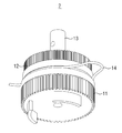
도 2는 본 발명의 일 실시예에 따른 차량용 변속기 제어 장치의 전체 구조를 나타낸 것이다.
도 3은 동일한 변속기 제어 장치의 전체 구조를 저면에서 나타낸 도면이다.
도 4는 본 발명의 일 실시예에 따른 차량용 변속기 제어 장치의 복수의 기어 유닛의 외관을 나타낸 사시도이다.
도 5는 본 발명의 일 실시예에 따른 차량용 변속기 제어 장치의 복수의 기어 유닛의 외관을 저면에서 나타낸 사시도이다.
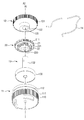
도 6은 본 발명의 일 실시예에 따른 차량용 변속기 제어 장치의 복수의 기어 유닛을 나타낸 분해 사시도이다.
도 7은 본 발명의 일 실시예에 따른 차량용 변속기 제어 장치의 복수의 기어 유닛을 저면에서 나타낸 분해 사시도이다.
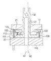
도 8은 본 발명의 일 실시예에 따른 차량용 변속기 제어 장치의 복수의 기어 유닛을 나타낸 측단면도이다.
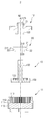
도 9는 본 발명의 일 실시예에 따른 차량용 변속기 제어 장치의 복수의 기어 유닛의 분해된 모습을 나타낸 측단면도이다.
도 10은 본 발명의 일 실시예에 따른 차량용 변속기 제어 장치의 복수의 기어 유닛을 제2 기어 유닛이 드러나도록 아래에서 바라본 모습을 나타낸 저면도이다.
도 11은 본 발명의 일 실시예에 따른 차량용 변속기 제어 장치의 복수의 기어 유닛을 메인 샤프트가 드러나도록 아래에서 바라본 모습을 나타낸 저면도이다.
도 12는 본 발명의 일 실시예에 따른 차량용 변속기 제어 장치의 복수의 기어 유닛을 제2 기어 유닛이 드러나도록 위에서 바라본 모습을 나타낸 평면도이다.
도 13은 본 발명의 일 실시예에 따른 차량용 변속기 제어 장치의 메인 구동부가 동작하는 상황을 나타낸 도면이다.
도 14는 본 발명의 일 실시예에 따른 차량용 변속기 제어 장치의 메인 구동부가 동작할 때 제2 기어 유닛의 동작을 나타낸 도면이다.
도 15는 본 발명의 일 실시예에 따른 차량용 변속기 제어 장치의 메인 구동부가 동작할 때 제2 외접 기어와 제2 내접 기어의 동작을 나타낸 도면이다.
도 16은 본 발명의 일 실시예에 따른 차량용 변속기 제어 장치의 복귀 유닛이 동작하는 상황을 나타낸 도면이다.
도 17은 본 발명의 일 실시예에 따른 차량용 변속기 제어 장치의 복귀 유닛이 동작할 때 제2 기어 유닛의 동작을 나타낸 도면이다.
도 18은 본 발명의 일 실시예에 따른 차량용 변속기 제어 장치의 복귀 유닛이 동작할 때 제2 외접 기어와 제2 내접 기어의 동작을 나타낸 도면이다.Fig. 1 shows the construction of a general electronic automatic transmission.
2 is a diagram illustrating the overall structure of a vehicle transmission control apparatus according to an embodiment of the present invention.
3 is a bottom view showing the entire structure of the same transmission control device.
4 is a perspective view showing the appearance of a plurality of gear units of a vehicular transmission control device according to an embodiment of the present invention.
5 is a perspective view showing the outer appearance of a plurality of gear units of a vehicular transmission control device according to an embodiment of the present invention.
6 is an exploded perspective view showing a plurality of gear units of a vehicular transmission control device according to an embodiment of the present invention.
7 is an exploded perspective view showing a plurality of gear units of a vehicular transmission control apparatus according to an embodiment of the present invention, viewed from the bottom.
8 is a side sectional view showing a plurality of gear units of a vehicular transmission control device according to an embodiment of the present invention.
9 is a side cross-sectional view showing an exploded view of a plurality of gear units of the vehicular transmission control device according to the embodiment of the present invention.
10 is a bottom view showing a plurality of gear units of the vehicular transmission control apparatus according to an embodiment of the present invention as viewed from below so that the second gear unit is exposed.
11 is a bottom view showing a plurality of gear units of a vehicular transmission control apparatus according to an embodiment of the present invention as viewed from below so that the main shaft is exposed.
FIG. 12 is a plan view showing a plurality of gear units of the control apparatus for a vehicle transmission according to an embodiment of the present invention, as viewed from above, so that the second gear unit is exposed.
13 is a diagram illustrating a state in which the main drive unit of the vehicular transmission control apparatus according to the embodiment of the present invention operates.
14 is a diagram illustrating the operation of the second gear unit when the main drive unit of the vehicular transmission control apparatus according to the embodiment of the present invention is operated.
15 is a diagram illustrating the operation of the second external gear and the second internal gear when the main drive of the vehicular transmission control apparatus operates according to an embodiment of the present invention.
16 is a view showing a state in which the return unit of the control device for a vehicle transmission according to the embodiment of the present invention operates.
17 is a diagram illustrating the operation of the second gear unit when the return unit of the vehicular transmission control apparatus according to the embodiment of the present invention operates.
18 is a view showing the operation of the second external gear and the second internal gear when the return unit of the vehicular transmission control apparatus according to the embodiment of the present invention operates.
본 발명의 이점 및 특징, 그리고 그것들을 달성하는 방법은 첨부되는 도면과 함께 상세하게 후술되어 있는 실시예들을 참조하면 명확해질 것이다. 그러나 본 발명은 이하에서 개시되는 실시예들에 한정되는 것이 아니라 서로 다른 다양한 형태로 구현될 수 있으며, 단지 본 실시예들은 본 발명의 개시가 완전하도록 하고, 본 발명이 속하는 기술분야에서 통상의 지식을 가진 자에게 발명의 범주를 완전하게 알려주기 위해 제공되는 것이며, 본 발명은 청구항의 범주에 의해 정의될 뿐이다. 명세서 전체에 걸쳐 동일 참조 부호는 동일 구성 요소를 지칭한다.BRIEF DESCRIPTION OF THE DRAWINGS The advantages and features of the present invention, and the manner of achieving them, will be apparent from and elucidated with reference to the embodiments described hereinafter in conjunction with the accompanying drawings. The present invention may, however, be embodied in many different forms and should not be construed as limited to the embodiments set forth herein. Rather, these embodiments are provided so that this disclosure will be thorough and complete, and will fully convey the scope of the invention to those skilled in the art. To fully disclose the scope of the invention to those skilled in the art, and the invention is only defined by the scope of the claims. Like reference numerals refer to like elements throughout the specification.
다른 정의가 없다면, 본 명세서에서 사용되는 모든 용어(기술 및 과학적 용어를 포함)는 본 발명이 속하는 기술분야에서 통상의 지식을 가진 자에게 공통적으로 이해될 수 있는 의미로 사용될 수 있을 것이다. 또 일반적으로 사용되는 사전에 정의되어 있는 용어들은 명백하게 특별히 정의되어 있지 않는 한 이상적으로 또는 과도하게 해석되지 않는다.Unless defined otherwise, all terms (including technical and scientific terms) used herein may be used in a sense commonly understood by one of ordinary skill in the art to which this invention belongs. Also, commonly used predefined terms are not ideally or excessively interpreted unless explicitly defined otherwise.
본 명세서에서 사용된 용어는 실시예들을 설명하기 위한 것이며 본 발명을 제한하고자 하는 것은 아니다. 본 명세서에서, 단수형은 문구에서 특별히 언급하지 않는 한 복수형도 포함한다. 명세서에서 사용되는 "포함한다(comprises)" 및/또는 "포함하는(comprising)"은 언급된 구성요소 외에 하나 이상의 다른 구성요소의 존재 또는 추가를 배제하지 않는다.The terminology used herein is for the purpose of illustrating embodiments and is not intended to be limiting of the present invention. In the present specification, the singular form includes plural forms unless otherwise specified in the specification. The terms " comprises "and / or" comprising "used in the specification do not exclude the presence or addition of one or more other elements in addition to the stated element.
또한, 본 명세서에서 기술하는 실시예들은 본 발명의 이상적인 예시도인 단면도 및/또는 개략도들을 참고하여 설명될 것이다. 따라서, 제조 기술 및/또는 허용 오차 등에 의해 예시도의 형태가 변형될 수 있다. 또한 본 발명에 도시된 각 도면에 있어서 각 구성 요소들은 설명의 편의를 고려하여 다소 확대 또는 축소되어 도시된 것일 수 있다. 명세서 전체에 걸쳐 동일 참조 부호는 동일 구성 요소를 지칭하며, "및/또는"은 언급된 아이템들의 각각 및 하나 이상의 모든 조합을 포함한다.Further, the embodiments described herein will be described with reference to cross-sectional views and / or schematic drawings that are ideal illustrations of the present invention. Thus, the shape of the illustrations may be modified by manufacturing techniques and / or tolerances. In addition, in the drawings of the present invention, each component may be somewhat enlarged or reduced in view of convenience of explanation. Like reference numerals refer to like elements throughout the specification and "and / or" include each and every combination of one or more of the mentioned items.
이하, 첨부된 도면을 참조하여 본 발명의 바람직한 실시예의 구성을 상세히 설명하기로 한다.Hereinafter, the configuration of a preferred embodiment of the present invention will be described in detail with reference to the accompanying drawings.
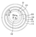
도 2는 본 발명의 일 실시예에 따른 차량용 변속기 제어 장치(1)의 전체 구조를 나타낸 것이다. 도 3은 동일한 변속기 제어 장치(1)의 전체 구조를 하방에서 바라본 도면이다.2 shows the overall structure of the vehicular
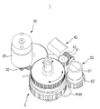
도 2 및 도 3을 참조하면, 본 발명의 변속기 제어 장치(1)는 메인 구동부(30), 메인 구동부(30)와 연결된 복수의 기어 유닛(2), 복수의 기어 유닛(2)에 연결된 복귀 유닛(40) 및 복수의 기어 유닛(2)에 연결된 감지 유닛(50)으로 구성됨을 확인할 수 있다.2 and 3, the
메인 구동부(30)는 TCU로부터 제어 신호를 받아 변속기의 변속단을 제어하도록 구동된다. 따라서 신호를 받아 물리적인 힘을 기계 장치에 가할 수 있는 모터(31)를 포함하고, 원하는 감속비를 얻기 위하여 복수의 기어 유닛(2)과 연결되는 별도의 기어 어셈블리(32)를 더 포함할 수 있다. 본 발명의 일 실시예에서는 기어 어셈블리(32)를 통해 모터(31)와 복수의 기어 유닛(2)이 연결되는 것으로 도시하였으나, 메인 구동부(30)의 구성은 이에 제한되지 않고 목적에 따라 다양한 변형이 가능하다. The
복귀 유닛(40)은 변속기의 변속단을 주차단으로 복귀시키기 위해 구동되는 구성요소이다. 따라서 제어 신호를 받아 작동하는 액추에이터(43)를 포함하고, 별도의 기어 어셈블리를 통해 액추에이터(43)와 복수의 기어 유닛(2)을 연결하도록 할 수 있다. 본 발명의 일 실시예에서는 액추에이터(43)의 구동축에 결합된 웜(41) 및 상기 웜(41)에 치합되는 하나의 웜 휠(42)이 복수의 기어 유닛(2)에 치합되어 연결되는 것으로 도시하였으나, 복귀 유닛(40)의 구성은 이에 제한되지 않고 목적에 따라 다양한 변형이 가능하다. The
감지 유닛(50)은 메인 구동부(30)의 구동에 의해 변속기의 변속단이 어디 위치한지를 파악하는 구성요소이다. 또한 메인 구동부(30)를 제어하기 위한 피드백 신호를 생성하기 위해서 사용될 수도 있다. 따라서 감지 유닛(50)은 메인 구동부(30)에 의해 회전하는 제1 기어 유닛(11)에 연결되어, 제1 기어 유닛(11)의 회전에 따라 같이 회전하여 그 회전 정도를 감지할 수 있다. The
회전된 정도를 감지하기 위해 본 발명의 일 실시예에서는 제1 기어 유닛(11)의 외주면에 치합된 감지 유닛(50)을 이용하였으나 메인 구동부(30)의 구동량을 감지하는 방법은 이에 제한되지 않는다. 감지 유닛(50)으로는 이는 수평 방향으로 양 극이 위치하는 마그넷 및 2D 자력 센서(51)가 사용될 수 있으나 이에 제한되지 않고 회전량을 측정하는 엔코더 등의 부재를 사용할 수도 있다.The
복수의 기어 유닛(2)은 변속기로 연결되는 메인 샤프트(13)를 포함하는 기어 유닛들의 집합으로, 외주면의 각기 다른 위치에서 메인 구동부(30), 복귀 유닛(40) 및 감지 유닛(50)과 각각 연결된다. 복수의 기어 유닛(2)은 다른 구성요소들과 면대 면으로 만날수도 있으나, 기어치가 형성되어 치합될 수도 있다. The plurality of
복수의 기어 유닛(2)의 외관에 대해서는 도 3 내지 도 4를 참조하여 설명한다.The appearance of the plurality of
도 4는 본 발명의 일 실시예에 따른 차량용 변속기 제어 장치(1)의 복수의 기어 유닛(2)의 외관을 나타낸 사시도이고, 도 5는 동일한 변속기 제어 장치(1)를 저면에서 나타낸 사시도이다.Fig. 4 is a perspective view showing the appearance of a plurality of
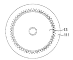
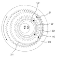
복수의 기어 유닛(2)을 외부에서 봤을 때, 제1 기어 유닛(11)의 상방에 제3 기어 유닛(12)이 안착되고 제3 기어 유닛(12)에 형성된 제2 중공(123)을 통해 메인 샤프트(13)가 노출되어 있다. The
제1 기어 유닛(11)의 하측 외주면에는 기어치가 형성되어서 메인 구동부(30) 및 감지 유닛(50)과 각각 다른 위치에서 치합된다. 따라서 메인 구동부(30)의 구동에 따라 제1 기어 유닛(11)이 회전력을 전달받아 회전하게 되고, 제1 기어 유닛(11)이 회전함에 따라 감지 유닛(50)이 회전하여 그 회전량을 측정하게 된다.Gear teeth are formed on the lower outer circumferential surface of the
또한 제1 기어 유닛(11)의 상측 외주면에는 홈(112)이 형성되어, 제1 잠금 유닛(14)이 접촉될 수 있다. 제1 잠금 유닛(14)은 제1 기어 유닛(11)의 회전을 제한하는 구성요소로, 본 발명의 일 실시예에서는 제1 잠금 유닛(14)의 홈(112)에 안착되는 마찰 스프링으로 구성하였으나 이에 제한되지 않는다.Further,
제1 기어 유닛(11)이 메인 구동부(30)가 전달한 회전력에 의해 회전함으로써, 메인 샤프트(13)가 회전하게 되고, 변속기에 연결된 메인 샤프트(13)를 통해 변속기의 변속단을 제어하게 된다. The
제1 기어 유닛(11)의 상측에는 제3 기어 유닛(12)이 안착된다. 제3 기어 유닛(12)은 중앙에 제2 중공(123)을 가져 샤프트가 관통하도록 하도록 구성된다. 자세한 설명은 후술한다.And the
복귀 유닛(40)은 제2 잠금 유닛을 더 포함할 수 있다. 제2 잠금 유닛은 제3 기어 유닛(12)의 회전을 제한한다. 본 발명의 일 실시예에서는 복귀 유닛(40)을 구성하는 웜(41)과 웜 휠(42)에 의해서 셀프 락(self-lock)이 일어나 제3 기어 유닛(12)의 회전을 제한하는 것으로, 제2 잠금 유닛이 복귀 유닛(40)의 구조에 의해 구현되는 것으로 표현하였으나, 제1 잠금 유닛(14)과 같이 별도의 구성을 가질 수 있으며 이에 제한되지 않는다.The
복귀 유닛(40)은 웜(41)과 웜 휠(42)이 액추에이터(43)에 의해 구동되는 방식으로 작동하므로, 액추에이터(43)가 동작을 멈추는 것으로 셀프 락(self-lock)이 일어나 제3 기어 유닛(12)의 회전을 제한할 수 있다. 그러나 복귀 유닛(40)은 그밖에도 조건에 따라 웜(41) 또는 웜 휠(42)의 회전을 규제하도록 형성되는 별도의 제2 잠금 유닛(미도시)을 더 포함하여, 제3 기어 유닛(12)의 회전을 제한할 수 있다.The
복수의 기어 유닛(2)의 자세한 내부 구조에 대해서는 도 5 내지 도 8을 참조하여 설명한다.The detailed internal structure of the plurality of
도 6은 본 발명의 일 실시예에 따른 차량용 변속기 제어 장치(1)의 복수의 기어 유닛(2)을 나타낸 분해 사시도이고, 도 7은 이를 저면에서 나타낸 분해 사시도이다. 도 8은 본 발명의 일 실시예에 따른 차량용 변속기 제어 장치(1)의 복수의 기어 유닛(2)을 나타낸 측단면도이고, 도 9는 본 발명의 일 실시예에 따른 차량용 변속기 제어 장치(1)의 복수의 기어 유닛(2)의 분해된 모습을 나타낸 측단면도이다.FIG. 6 is an exploded perspective view showing a plurality of
본 발명의 일 실시예에 따른 차량용 변속기 제어 장치(1)의 복수의 기어 유닛(2)은 제1 기어 유닛(11), 제2 기어 유닛(20) 및 제3 기어 유닛(12)으로 구성된다. The plurality of
제1 기어 유닛(11)은 제1 회전축(A1)을 중심으로 회전하는 기어 유닛이다. 제1 기어 유닛(11)은 상술한 바와 같이 외주면을 통해서 감지 유닛(50)과 메인 구동부(30)에 연결된다. 따라서 메인 구동부(30)의 구동력을 전달받아 제1 회전축(A1)을 중심으로 회전한다.The
제1 기어 유닛(11)은 다시 제1 내접 기어(111)와 외접부(110)로 나뉜다. 제1 기어 유닛(11)은 상측에 제1 내접 기어(111)가 형성되고, 하측에 외접부(110)가 형성되어 제1 내접 기어(111)와 외접부(110)가 일체로 작용한다. 제1 기어 유닛(11)의 외접부(110)는 외주면을 따라서 기어치가 형성되어 메인 구동부(30)와 연결된다. 메인 구동부(30)에 의해 전달된 구동력에 의해 외접부(110)가 회전함으로써 외접부(110)와 일체형으로 형성된 제1 내접 기어(111)가 동일하게 회전한다.The
제1 내접 기어(111)의 외주면에는 상술한 홈(112)이 형성될 수 있으나, 홈(112)의 위치는 이에 제한되지 않고 외접부(110)에 형성될 수도 있다. 제1 내접 기어(111)의 내주면에는 기어치가 형성되어 후술할 제2 기어 유닛(20)의 제1 외접 기어(21)와 맞물리도록 연결된다.The
메인 샤프트(13)는 변속기로 복수의 기어 유닛(2)이 전달받은 회전력을 전달하는 구성요소로, 제1 회전축(A1)을 중심으로 회전하고, 샤프트부(132)와 제2 내접 기어(130)로 나뉜다. The
샤프트부(132)는 변속기와 연결되어 회전력을 전달하도록, 상하방으로 연장되어 제3 기어 유닛(12)의 제2 중공(123) 및 제2 기어 유닛(20)의 제1 중공(210, 220)을 관통하도록 형성된다. The
제2 내접 기어(130)는 샤프트부(132)의 하단에 위치해 복수의 기어 유닛(2) 내부의 공간에 수용되고, 원판형으로 형성됨과 동시에 내주면에 기어치가 형성된다. 따라서 제1 내접 기어(111)의 내부에 수용되어야 하므로 제2 내접 기어(130)는 제1 내접 기어(111)의 내경보다 작은 외경을 가진다.The second
제2 내접 기어(130)의 내측면에 형성된 기어치(133)에는 제2 기어 유닛(20)의 제2 외접 기어(22)가 맞물려 치합된다. 즉, 제1 기어 유닛(11)의 제1 내접 기어(111)와 제2 기어 유닛(20)의 제1 외접 기어(21)가 치합되고, 메인 샤프트(13)의 제2 내접 기어(130)와 제2 기어 유닛(20)의 제2 외접 기어(22)가 치합되는 것이다. The second
제2 기어 유닛(20)은 제1 외접 기어(21)와 제2 외접 기어(22)를 포함한다. 제1 외접 기어(21)와 제2 외접 기어(22)가 서로 상하방으로 결합되어 동일한 중심축선인 제2 회전축(A2) 또는 중심을 통과하지 않는 제1 회전축(A1)을 따라 회전할 수 있도록 구성되고, 상기 제2 회전축(A2)은 메인 샤프트(13)의 중심축인 제1 회전축(A1)으로부터 이격되게 위치한다. 따라서 제2 기어 유닛(20)의 중심축인 제2 회전축(A2)이 메인 샤프트(13), 제1 기어 유닛(11) 및 후술할 제3 기어 유닛(12)의 중심축인 회전축(A1)으로부터 편심되므로 제2 기어 유닛(20)은 제1 기어 유닛(11)에 대해 편심된 위치에 배치되어 작동한다.The second gear unit (20) includes a first external gear (21) and a second external gear (22). The first
제2 기어 유닛(20)을 구성하는 제1 외접 기어(21) 및 제2 외접 기어(22)의 중심에는 제1 중공(210, 220)이 형성된다. 제1 중공(210, 220)은 메인 샤프트(13)의 샤프트부(132)가 관통하는 제3 기어 유닛(12)의 돌출부(122)가 통과하는 개구부이다. 제1 중공(210, 220)은 원형의 통공으로 형성되는데, 그 원의 중심을 제2 회전축(A2)이 지나간다. 따라서 돌출부(122)가 제1 중공(210, 220)에 삽입된 상황에서, 제2 기어 유닛(20)은 제3 기어 유닛(12)에 안착됨과 동시에 돌출부(122)를 중심으로 자전할 수 있다. 돌출부(122)의 회전축이 제2 기어 유닛(20)의 회전축인 제2 회전축(A2)과 동일하기 때문이다.The
제2 기어 유닛(20)을 구성하는 제1 외접 기어(21) 및 제2 외접 기어(22)의 외주면을 따라서는 기어치(211, 221)가 형성되어, 제1 외접 기어(21)는 제1 내접 기어(111)에 치합되고 제2 외접 기어(22)는 제2 내접 기어(130)에 치합된다. 그러나 제1 외접 기어(21)의 직경은 제1 내접 기어(111)의 내경보다 작고, 제2 외접 기어(22)의 직경은 제2 내접 기어(130)의 내경보다 작도록 구성된다. 따라서 각각 일부의 기어치만이 일 내측면에 맞물려 있을 뿐, 전체 기어치가 치합되도록 구성되지 않는다. 이로 인해 제2 기어 유닛(20)이 각 내접 기어의 내주면에 형성된 기어치(113, 133)와 맞물려서 자전함과 동시에, 상기 자전축이 다른 회전축을 중심으로 공전할 수 있다. 제1 외접 기어(21) 및 제2 외접 기어(22)가, 자전함과 동시에 제1 내접 기어(111)와 제2 내접 기어(130)의 내주를 따라 이동하는 것이다. 또한, 제1 기어 유닛(11)의 내부에 수용되는 제2 내접 기어(130)는 그 외경이 제1 기어 유닛(11)에 비해 작고, 제1 외접 기어(21)의 직경에 비해서 제2 외접 기어(22)의 직경이 작도록 구성해 각각 맞물리는 내접 기어에 수용 및 치합되도록 할 수 있다. The
따라서, 제1 외접 기어(21) 및 제2 외접 기어(22)는 제1 회전축(A1)과 상이한 제2 회전축(A2)를 중심축으로 가지게 되는데, 이는 제1 외접 기어(21) 및 제2 외접 기어(22)가 제2 회전축(A2)을 중심으로 자전하도록 함과 동시에 제2 회전축(A2)이 제1 회전축(A1)을 중심으로 공전하도록 하여 서로 맞물리는 기어의 직경 차이를 크게 하지 않고도 높은 기어비를 구현함으로써 충분한 감속 효과를 얻으면서도 소형화에 유리하도록 하기 위함이다.Therefore, the first
제3 기어 유닛(12)은 몸체부(124) 및 돌출부(122)를 포함한다. The
제3 기어 유닛(12)의 몸체부(124)는 외주면에 기어치가 형성되어 복귀 유닛(40)과 치합되어 연결된다. 따라서 복귀 유닛(40)의 액추에이터(43)가 회전함에 따라 제3 기어 유닛(12)도 회전하게 되고, 복귀 유닛(40)이 제2 잠금 유닛의 작용으로 인해 구동이 제한되는 경우, 그 회전이 제한된다.The
돌출부(122)는 몸체부(124)의 하면에서 하방으로 연장되어 형성되며, 내부에 제2 중공(123)이 형성된다. 돌출부(122)는 제2 기어 유닛(20)의 중심축인 제2 회전축(A2)을 중심으로 하는 원기둥의 형태로 형성되나, 제2 중공(123)은 메인 샤프트(13)의 중심축인 제1 회전축(A1)을 중심으로 하는 원기둥의 형태로 개방된 개구이다. 상술한 바와 같이, 제2 기어 유닛(20)이 제2 회전축(A2)을 중심으로 회전하고자 할 때, 돌출부(122)가 그 회전축이 될 수 있다.The
그 밖에도 제3 기어 유닛(12)의 몸체부(124)에는 제2 중공(123)을 관통하여 돌출된 샤프트부(132)를 감싸는 테두리(121)부가 상면에 더 형성될 수도 있다. In addition, the
본 발명의 실시예에서는 복수의 기어 유닛(2)이 3개의 기어 유닛으로 구성되는 경우를 예를 들어 설명하고 있으나, 이는 본 발명의 이해를 돕기 위한 일 예에 불과한 것으로서, 이에 한정되지 않고 기어비나 설계 상의 이유 등에 따라 기어 유닛의 개수는 다양하게 변경될 수 있다.In the embodiment of the present invention, the case where the plurality of
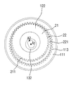
도 10은 본 발명의 일 실시예에 따른 차량용 변속기 제어 장치(1)의 복수의 기어 유닛(2)을 제2 기어 유닛(20)이 드러나도록 아래에서 바라본 모습을 나타낸 저면도이다.10 is a bottom view showing a state in which a plurality of
도 10을 참조하면, 제2 기어 유닛(20)이 드러날 수 있도록 제1 기어 유닛(11)의 외접부(110)와 메인 샤프트(13)를 제거한 뒤 아래에서 복수의 기어 유닛(2)을 바라본 상황을 확인할 수 있다. 도 10에서 확인할 수 있듯이, 제1 기어 유닛(11)과 메인 샤프트(13)의 회전축인 제1 회전축(A1)과, 제2 기어 유닛(20)의 회전축인 제2 회전축(A2)은 서로 평행하나 일치하지 않고 이격되어있다. 따라서 제1 기어 유닛(11) 내에서 제2 기어 유닛(20)이 편심된 위치에 배치된다. 제2 회전축(A2)은 제1 회전축(A1)으로부터 이격되어 위치함과 동시에, 제2 회전축(A2)을 회전축으로 하는 제2 기어 유닛(20)의 제1 외접 기어(21)가 제1 내접 기어(111)의 내측면 중 일부 영역에 치합되고, 제2 외접 기어(22)가 제2 내접 기어(130)의 내측면 중 일부 영역에 치합되는 위치에 배치된다. 10, the outer
도 11은 본 발명의 일 실시예에 따른 차량용 변속기 제어 장치(1)의 복수의 기어 유닛(2)을 메인 샤프트(13)가 드러나도록 아래에서 바라본 모습을 나타낸 저면도이다.11 is a bottom view showing a state in which a plurality of
도 11을 참조하면, 메인 샤프트(13) 중 가장 하측에 위치한 제2 내접 기어(130)의 하면이 노출될 수 있도록 제1 기어 유닛(11)의 외접부(110)를 제거한 뒤 아래에서 복수의 기어 유닛(2)을 바라본 상황을 확인할 수 있다. 제1 기어 유닛(11)의 제1 내접 기어(111) 안에 제2 내접 기어(130)가 수용된다. 따라서 제2 내접 기어(130)는 제1 내접 기어(111)의 내경보다 작은 직경을 가진다.11, a circumscribed
도 12는 본 발명의 일 실시예에 따른 차량용 변속기 제어 장치(1)의 복수의 기어 유닛(2)을 제2 기어 유닛(20)이 드러나도록 위에서 바라본 모습을 나타낸 평면도이다.12 is a plan view showing a state in which a plurality of
도 12를 참조하면, 메인 샤프트(13)와 제2 기어 유닛(20)의 위치관계를 확인할 수 있도록, 제3 기어 유닛(12)을 제거한 후 상방에서 복수의 기어 유닛(2)을 바라본 상황을 확인할 수 있다. 제1 외접 기어(21)에 비해서 더 작은 직경을 가지는 제2 외접 기어(22)는 확인할 수 없고, 제1 외접 기어(21), 메인 샤프트(13)의 샤프트부(132) 및 제1 내접 기어(11)의 위치관계를 확인할 수 있다.12, after the
제1 외접 기어(21)는 제3 기어 유닛(12)의 돌출부(122)에 삽입된다. 따라서 제1 회전축(A1)으로부터 이격된 제2 회전축(A2)을 가지므로, 제1 내접 기어(11)에 대해 편심된 위치에 배치된다. 따라서 제1 외접 기어(21)는 제1 내접 기어(111)의 내주면의 일부 영역에 치합된다. The first
메인 샤프트(13)의 샤프트부(132)는 제2 기어 유닛(20)의 제1 중공(210, 220)을 관통하는 돌출부(122)의 제2 중공(123)을 통과하므로, 제1 중공(210, 220)의 내부에 위치하는 것으로 표현된다.The
이하, 도 13 내지 도 15를 참조하여 본 발명의 차량용 변속기 제어 장치(1)의 메인 구동부(30)가 동작할 때, 전체 구조가 동작하는 과정을 설명한다.13 to 15, a description will be given of a process in which the entire structure operates when the
도 13은 본 발명의 일 실시예에 따른 차량용 변속기 제어 장치(1)의 메인 구동부(30)가 동작하는 상황을 나타낸 도면이다. 도 14는 본 발명의 일 실시예에 따른 차량용 변속기 제어 장치(1)의 메인 구동부(30)가 동작할 때 제2 기어 유닛(20)의 동작을 나타낸 도면이다. 도 15는 본 발명의 일 실시예에 따른 차량용 변속기 제어 장치(1)의 메인 구동부(30)가 동작할 때 제2 외접 기어(22)와 제2 내접 기어(130)의 동작을 나타낸 도면이다.13 is a diagram illustrating a state in which the
시프트 레버를 운전자가 조작하면, 시프트 레버는 변속단을 변경하기 위한제어 신호를 생성하고 변속기 제어 장치(1)로 전달한다. 메인 구동부(30)가 상기 제어 신호를 받아 변속단을 제어하기 위해 구동되면, 메인 구동부(30)와 연결된 제1 기어 유닛(11)의 외접부(110)가 구동력을 전달받아 회전하고, 외접부(110)와 일체로 외접부(110)의 상방에 형성된 제1 내접 기어(111)가 동일하게 회전한다. 메인 구동부(30)가 발생시키는 구동력을 제1 구동력이라고 지칭한다. When the driver operates the shift lever, the shift lever generates a control signal for changing the speed change stage and transmits the control signal to the
제1 잠금 유닛(14)은 제1 내접 기어(111)의 회전을 규제하지 않는다. 제1 잠금 유닛(14)으로 마찰 스프링이 사용되는 경우, 제1 내접 기어(111)가 전달받은 제1 구동력이 마찰 스프링이 가하는 최대정지마찰력에 비해 크도록 마찰 스프링을 구성해, 제1 내접 기어(111)의 회전이 이루어진다. 비록 제1 잠금 유닛(14)에 의해 제1 내접 기어(111)의 회전을 방해하는 마찰력이 작용할 것이나, 마찰력보다 큰 제1 구동력이 구동부(30)에 의해 제1 내접 기어(111)에 작용해 회전이 규제되지 않는 것이다. 또한 복귀 유닛(40)이 작동하지 않고, 제2 잠금 유닛에 의해 액추에이터(43)의 구동이 제한됨으로써, 제3 기어 유닛(12)의 회전이 일어나지 않고 고정되도록 한다.The
제1 내접 기어(111)가 회전함으로써, 제1 내접 기어(111)에 치합된 제1 외접 기어(21)가 회전한다. 이 때, 제1 외접 기어(21)가 포함하는 제1 중공(210, 220)이 제3 기어 유닛(12)의 돌출부(122)를 수용하여 제1 외접 기어(21)가 제3 기어 유닛(12)에 안착되고, 제3 기어 유닛(12)은 고정되어 있으므로 제1 외접 기어(21)는 돌출부(122)를 축으로 해서 제2 회전축(A2)을 중심으로 회전한다. 제2 회전축(A2)을 기준으로 한 자전만이 제2 기어 유닛(20)에 대해서 일어나는 것이다.As the first
제1 외접 기어(21)가 회전함에 따라, 제2 외접 기어(22)도 동일한 축을 중심으로 회전하고, 제2 외접 기어(22)에 치합된 제2 내접 기어(130)도 회전한다. 제2 내접 기어(130)는 메인 샤프트(13)의 구성요소이므로, 제2 외접 기어(22)의 회전력을 전달받아 제1 회전축(A1)을 중심으로 회전한다. 따라서 메인 샤프트(13) 역시 제2 내접 기어(130)의 회전에 의해 회전하고, 회전력을 변속기로 전달하게 된다.As the first
이와 같은 과정을 통해 메인 구동부(30)가 복수의 기어 유닛(2)에 전달한 제1 구동력이 회전운동을 통해 변속기에 회전력으로 전달된다. 이 때, 제1 기어 유닛(11)의 외접부(110)에는 감지 유닛(50)이 치합되므로, 제1 기어 유닛(11)의 회전량을 감지 유닛(50)이 측정하고 이용할 수 있다.Through the above process, the first driving force transmitted to the plurality of
이하, 도 16 내지 도 18를 참조하여 본 발명의 차량용 변속기 제어 장치(1)의 복귀 유닛(40)이 동작할 때, 전체 구조가 동작하는 과정을 설명한다.Hereinafter, the operation of the entire structure when the
도 16은 본 발명의 일 실시예에 따른 차량용 변속기 제어 장치(1)의 복귀 유닛(40)이 동작하는 상황을 나타낸 도면이다. 도 17은 본 발명의 일 실시예에 따른 차량용 변속기 제어 장치(1)의 복귀 유닛(40)이 동작할 때 제2 기어 유닛(20)의 동작을 나타낸 도면이다. 도 18은 본 발명의 일 실시예에 따른 차량용 변속기 제어 장치(1)의 복귀 유닛(40)이 동작할 때 제2 외접 기어(22)와 제2 내접 기어(130)의 동작을 나타낸 도면이다.16 is a diagram showing a state in which the
복귀 유닛(40)이 제어 신호를 받아 변속단을 주차단으로 변경하기 위해 구동되면, 복귀 유닛(40)과 연결된 제3 기어 유닛(12)이 구동력을 전달받아 회전한다. 복귀 유닛(40)이 발생시킨 구동력을 제2 구동력이라 지칭한다.When the
제3 기어 유닛(12)의 회전축은 제1 회전축(A1)과 동일하므로, 이 회전축을 중심으로 제3 기어 유닛(12)이 회전함으로써, 제3 기어 유닛(12)의 하면에 형성된 돌출부(122)가 동일한 회전축을 중심으로 회전한다. The
제1 외접 기어(21)가 포함하는 제1 중공(210, 220)이 제3 기어 유닛(12)의 돌출부(122)를 수용하여 제1 내접 기어(111)에 치합되는 제1 외접 기어(21)가 제3 기어 유닛(12)에 안착되어 있으므로, 돌출부(122)의 회전에 의해 제1 외접 기어(21) 역시 상기 회전축을 중심으로 회전하게 된다. 따라서 제1 외접 기어(21)의 중심을 지나는 제2 회전축(A2) 역시 제1 회전축(A1)을 중심으로 회전하게 된다.The
제1 내접 기어(111)와 제1 외접 기어(21)가 치합되어 있으므로, 제1 외접 기어(21)의 회전에 의해 제1 기어 유닛(11)이 회전하려 할 수 있다. 그러나 제1 잠금 유닛(14)은 제1 기어 유닛(11)의 회전을 규제한다. 제1 잠금 유닛(14)으로 마찰 스프링이 사용되는 경우, 제1 기어 유닛(11)이 제1 외접 기어(21)에 의해 전달받은 회전력이 마찰 스프링이 가하는 최대정지마찰력에 비해 작아서, 제1 기어 유닛(11)가 회전하지 않는 것이다. 따라서 제2 회전축(A2)은 제1 회전축(A1)을 중심으로 공전하게 되고, 이로 인해 제1 외접 기어(21)는 제1 기어 유닛(11)의 내주면을 따라서 이동하게 된다.Since the first
제1 외접 기어(21)는 제1 기어 유닛(11)의 내주면을 따라 이동함과 동시에, 제1 내접 기어(111)의 내주면에 치합되어 있으므로 제2 회전축(A2)을 중심으로 자전 하게 된다. 제1 외접 기어(21)가 회전함에 따라, 제2 외접 기어(22)도 동일한 축을 중심으로 자전하고 동일한 경로로 이동한다. The first
제2 외접 기어(22)가 회전함에 따라, 제2 외접 기어(22)에 치합된 제2 내접 기어(130)도 회전한다. 제2 내접 기어(130)는 메인 샤프트(13)의 구성요소이므로, 제2 외접 기어(22)의 회전력을 전달받아 제1 회전축(A1)을 중심으로 회전한다. 따라서 메인 샤프트(13) 역시 제2 내접 기어(130)의 회전에 의해 회전하고, 회전력을 변속기로 전달하게 된다. 다만 제2 기어 유닛(20)의 회전축인 제2 회전축(A2)의 공전 없이 회전력을 전달받았던 메인 구동부(30)의 구동시와 달리, 제2 회전축(A2)의 공전과 함께 회전력을 전달받은 복귀 유닛(40)의 구동시에는 기어비가 상대적으로 커진다.As the second
이와 같은 과정을 통해 메인 구동부(30)가 복수의 기어 유닛(2)에 전달한 제2 구동력이 회전운동을 통해 변속기에 회전력으로 전달된다. 이 때, 제1 기어 유닛(11)의 외접부(110)에는 감지 유닛(50)이 치합되었으나 제1 기어 유닛(11)의 회전이 제1 잠금 유닛(14)의 작용에 의해 일어나지 못하므로, 제1 기어 유닛(11)의 회전량을 감지 유닛(50)이 측정할 수 없다.Through the above process, the second driving force transmitted to the plurality of
변속기는 복귀 유닛(40)의 구동력을 메인 샤프트(13)를 통해 전달받고, 변속단을 주차단으로 돌아가도록 한다. The transmission receives the driving force of the return unit (40) through the main shaft (13) and returns the speed change stage to the main cut-off.
본 발명이 속하는 기술분야의 통상의 지식을 가진 자는 본 발명이 그 기술적 사상이나 필수적인 특징을 변경하지 않고서 다른 구체적인 형태로 실시될 수 있다는 것을 이해할 수 있을 것이다. 그러므로 이상에서 기술한 실시예들은 모든 면에서 예시적인 것이며 한정적이 아닌 것으로 이해해야만 한다. 본 발명의 범위는 상기 상세한 설명보다는 후술하는 특허청구범위에 의하여 나타내어지며, 특허청구범위의 의미 및 범위 그리고 그 균등 개념으로부터 도출되는 모든 변경 또는 변형된 형태가 본 발명의 범위에 포함되는 것으로 해석되어야 한다.It will be understood by those skilled in the art that the present invention may be embodied in other specific forms without departing from the spirit or essential characteristics thereof. It is therefore to be understood that the above-described embodiments are illustrative in all aspects and not restrictive. The scope of the present invention is defined by the appended claims rather than the detailed description and all changes or modifications derived from the meaning and scope of the claims and their equivalents are to be construed as being included within the scope of the present invention do.
비록 본 발명이 상기 언급된 바람직한 실시예와 관련하여 설명되었지만, 발명의 요지와 범위로부터 벗어남이 없이 다양한 수정이나 변형을 하는 것이 가능하다. 따라서 첨부된 특허청구의 범위에는 본 발명의 요지에 속하는 한 이러한 수정이나 변형을 포함할 것이다.Although the present invention has been described in connection with the above-mentioned preferred embodiments, it is possible to make various modifications and variations without departing from the spirit and scope of the invention. Accordingly, it is intended that the appended claims cover all such modifications and variations as fall within the true spirit of the invention.
1 : 변속기 제어 장치
2 : 복수의 기어 유닛
11 : 제1 기어 유닛
12 : 제3 기어 유닛
13 : 메인 샤프트
14 : 제1 잠금 유닛
20 : 제2 기어 유닛
21 : 제1 외접 기어
22 : 제2 외접 기어
30 : 메인 구동부
31 : 모터
32 : 메인 기어 어셈블리
40 : 복귀 유닛
41 : 웜
42 : 웜 휠
43 : 액추에이터
50 : 감지 유닛
51 : 자력 센서
100 : 일반적인 변속 장치
101 : 노브
102 : TCU
103 : 변속기 제어 장치
104 : 변속기
110 : 외접부
111 : 제1 내접 기어
112 : 홈
113 : 제1 내접 기어치
121 : 테두리
122 : 돌출부
123 : 제2 중공
124 : 몸체부
130 : 제2 내접 기어
132 : 샤프트부
133 : 제2 내접 기어치
210, 220 : 제1 중공
211 : 제1 외접 기어치
221 : 제2 외접 기어치
A1 : 제1 회전축
A2 : 제2 회전축1: Transmission controller 2: Multiple gear units
11: first gear unit 12: third gear unit
13: main shaft 14: first lock unit
20: second gear unit 21: first external gear
22: second external gear 30: main drive
31: motor 32: main gear assembly
40: return unit 41: worm
42: Worm wheel 43: Actuator
50: sensing unit 51: magnetic force sensor
100: General transmission device 101: Knob
102: TCU 103: Transmission controller
104: Transmission 110:
111: first internal gear 112: groove
113: first internal gear teeth 121: rim
122: protrusion 123: second hollow
124: body portion 130: second internal gear
132: shaft portion 133: second internal gear teeth
210, 220: first hollow 211: first external gear teeth
221: second external gear teeth A1: first rotary shaft
A2:
Claims (18)
복귀 조건을 만족할 때 제2 구동력을 발생시키는 복귀 유닛; 및
상기 메인 구동부로부터 발생되는 상기 제1 구동력 또는 상기 복귀 유닛으로부터 발생되는 상기 제2 구동력을, 제1 회전축을 중심으로 회전하는 메인 샤프트로 전달하는 복수의 기어 유닛을 포함하며,
상기 복수의 기어 유닛은, 상기 메인 구동부에 연결되어 상기 제1 회전축을 중심으로 회전하는 제1 기어 유닛; 상기 제1 기어 유닛의 내주면과 상기 메인 샤프트에 맞물리도록 배치되며, 상기 제1 회전축으로부터 편심된 제2 회전축을 중심으로 회전할 수 있는 제2 기어 유닛; 및 상기 제2 기어 유닛이 안착되고, 상기 복귀 유닛과 연결되어 상기 복귀 조건을 만족할 때 상기 제1 회전축을 중심으로 회전하는 제3 기어 유닛을 포함하고,
상기 메인 샤프트는, 변속기에 연결되어 상기 복수의 기어 유닛으로부터 전달된 상기 제1 구동력 또는 상기 제2 구동력을 상기 변속기에 전달하는 변속기 제어 장치. A main driving unit for generating a first driving force in accordance with a speed change step control signal;
A returning unit for generating a second driving force when the returning condition is satisfied; And
And a plurality of gear units for transmitting the first driving force generated from the main driving unit or the second driving force generated from the return unit to a main shaft rotating around a first rotation axis,
The plurality of gear units may include: a first gear unit connected to the main drive unit and rotating about the first rotation shaft; A second gear unit disposed to be engaged with the inner circumferential surface of the first gear unit and the main shaft, and capable of rotating about a second rotational shaft eccentric to the first rotational shaft; And a third gear unit on which the second gear unit is seated and connected to the return unit to rotate about the first rotation axis when the return condition is satisfied,
Wherein the main shaft transmits the first driving force or the second driving force transmitted from the plurality of gear units to the transmission, the transmission being connected to the transmission.
상기 제1 기어 유닛은, 내주면을 따라 기어치가 형성되는 제1 내접 기어를 포함하고,
상기 제2 기어 유닛은, 상기 메인 샤프트가 관통하는 제1 중공을 포함하고,
상기 메인 샤프트는, 상기 제1 중공을 관통하며 상기 변속기와 연결되는 샤프트부; 및 상기 샤프트부의 일단에 원형으로 형성되고 내주면을 따라 기어치가 형성되는 제2 내접 기어를 포함하는, 변속기 제어 장치.The method according to claim 1,
The first gear unit includes a first internal gear formed with gear teeth along an inner peripheral surface thereof,
The second gear unit includes a first hollow through which the main shaft penetrates,
The main shaft includes: a shaft portion passing through the first hollow and connected to the transmission; And a second internal gear formed in a circular shape at one end of the shaft portion and having gear teeth formed along an inner peripheral surface thereof.
상기 제2 기어 유닛은,
상기 제1 내접 기어의 일 내측면과 맞물리도록 배치되는 제1 외접 기어; 및
상기 제1 외접 기어보다 작은 직경을 가지고, 상기 제2 내접 기어의 일 내측면과 맞물리도록 배치되는 제2 외접 기어를 더 포함하는 변속기 제어 장치.3. The method of claim 2,
The second gear unit includes:
A first external gear disposed to be engaged with a first internal surface of the first internal gear; And
Further comprising a second external gear having a smaller diameter than the first external gear and disposed to mesh with a first internal side surface of the second internal gear.
상기 제1 외접 기어는, 상기 제2 외접 기어의 상방에 일체로 형성되고,
상기 제1 외접 기어의 회전축과 상기 제2 외접 기어의 회전축은 일치하는, 변속기 제어 장치.The method of claim 3,
The first external gear is integrally formed above the second external gear,
The rotation axis of the first external gear and the rotation axis of the second external gear coincide with each other.
상기 제2 기어 유닛은,
상기 제1 외접 기어로 전달된 회전력을 상기 제2 외접 기어를 통해 상기 메인 샤프트로 전달하는 변속기 제어 장치.5. The method of claim 4,
The second gear unit includes:
And transmits the rotational force transmitted to the first external gear to the main shaft through the second external gear.
상기 제1 외접 기어 및 상기 제2 외접 기어는,
각각 상기 제1 내접 기어 및 상기 제2 내접 기어보다 작은 직경을 가지는 변속기 제어 장치.The method of claim 3,
Wherein the first external gear and the second external gear comprise:
Each having a smaller diameter than the first internal gear and the second internal gear.
상기 제1 기어 유닛은,
상기 제1 내접 기어의 하방에 형성되고, 외주면을 따라 기어치가 형성되어 상기 메인 구동부와 치합되며, 상면에 상기 메인 샤프트가 안착되는 외접부를 더 포함하는 변속기 제어 장치.3. The method of claim 2,
The first gear unit includes:
Further comprising a circumscribed portion formed below the first internal gear and having gear teeth formed along an outer circumferential surface thereof and meshing with the main drive portion and having the main shaft mounted on an upper surface thereof.
상기 복귀 유닛은 액추에이터를 포함하고,
상기 제3 기어 유닛은 상기 액추에이터와 연결되는 변속기 제어 장치.3. The method of claim 2,
Wherein the return unit includes an actuator,
And the third gear unit is connected to the actuator.
상기 액추에이터는,
상기 복귀 조건이 만족되어 상기 변속기를 주차단으로 복귀시킬 때 구동되어 상기 제3 기어 유닛을 회전시키며,
상기 메인 샤프트 및 상기 제2 기어 유닛은, 상기 제3 기어 유닛이 전달받은 회전력을 상기 변속기로 전달하는 차량용 변속 장치. 9. The method of claim 8,
Wherein the actuator comprises:
And when the return condition is satisfied and the transmission is returned to the main cut-off, the third gear unit is rotated,
Wherein the main shaft and the second gear unit transmit the rotational force transmitted by the third gear unit to the transmission.
상기 제3 기어 유닛은,
상기 제2 기어 유닛의 제1 중공에 삽입되고 상기 메인 샤프트의 샤프트부가 관통하는 제2 중공이 형성되는 돌출부를 포함하며,
상기 제2 회전축이 상기 돌출부의 중심을 지나가는 변속기 제어 장치.10. The method of claim 9,
The third gear unit includes:
And a second hollow inserted into the first hollow of the second gear unit and passing through a shaft portion of the main shaft,
And the second rotation axis passes the center of the protrusion.
상기 복귀 유닛이 구동될 때,
상기 제2 기어 유닛은, 상기 제2 회전축을 중심으로 자전하고,
상기 제2 회전축은, 상기 제1 회전축을 중심으로 공전하는 변속기 제어 장치.The method according to claim 1,
When the return unit is driven,
The second gear unit rotates about the second rotation axis,
And the second rotation shaft revolves around the first rotation shaft.
상기 메인 구동부가 구동될 때,
상기 제2 기어 유닛은, 상기 제2 회전축을 중심으로 자전하는 변속기 제어 장치.The method according to claim 1,
When the main driver is driven,
And the second gear unit rotates around the second rotation axis.
상기 제1 기어 유닛은, 상기 복귀 유닛이 구동될 때 상기 제1 기어 유닛의 회전을 규제하는 제1 잠금 유닛을 더 포함하는, 변속기 제어 장치.3. The method of claim 2,
Wherein the first gear unit further includes a first lock unit that restricts rotation of the first gear unit when the return unit is driven.
상기 제1 잠금 유닛은 마찰 스프링인 변속기 제어 장치.14. The method of claim 13,
And the first lock unit is a friction spring.
상기 제1 잠금 유닛은, 상기 제1 내접 기어의 외주면에 접촉하여 상기 제1 내접 기어에 마찰력을 작용하는 변속기 제어 장치.14. The method of claim 13,
Wherein the first lock unit is in contact with an outer circumferential surface of the first internal gear to apply a frictional force to the first internal gear.
상기 복귀 유닛은, 상기 메인 구동부가 구동될 때 상기 액추에이터의 구동을 규제함으로써 상기 제3 기어 유닛의 회전을 규제하는 제2 잠금 유닛을 더 포함하는 변속기 제어 장치. 9. The method of claim 8,
Wherein the return unit further includes a second lock unit that restricts rotation of the third gear unit by regulating driving of the actuator when the main drive unit is driven.
상기 복귀 유닛은, 상기 액추에이터의 구동축에 결합된 웜 및 상기 웜에 치합되고 상기 제3 기어 유닛에 치합되는 웜 휠을 더 포함하는 변속기 제어 장치.9. The method of claim 8,
Wherein the return unit further includes a worm coupled to a drive shaft of the actuator and a worm wheel engaged with the worm and engaged with the third gear unit.
상기 제1 기어 유닛의 외주면과 연결되어 상기 제1 기어 유닛의 회전을 감지하는 감지 유닛을 더 포함하는 변속기 제어 장치.The method according to claim 1,
And a sensing unit coupled to an outer circumferential surface of the first gear unit to sense rotation of the first gear unit.
Priority Applications (1)
| Application Number | Priority Date | Filing Date | Title |
|---|---|---|---|
| KR1020160181836A KR101942773B1 (en) | 2016-12-29 | 2016-12-29 | Controlling apparatus of automotive transmission using eccentric gear |
Applications Claiming Priority (1)
| Application Number | Priority Date | Filing Date | Title |
|---|---|---|---|
| KR1020160181836A KR101942773B1 (en) | 2016-12-29 | 2016-12-29 | Controlling apparatus of automotive transmission using eccentric gear |
Publications (2)
| Publication Number | Publication Date |
|---|---|
| KR20180077458A true KR20180077458A (en) | 2018-07-09 |
| KR101942773B1 KR101942773B1 (en) | 2019-01-28 |
Family
ID=62919417
Family Applications (1)
| Application Number | Title | Priority Date | Filing Date |
|---|---|---|---|
| KR1020160181836A Expired - Fee Related KR101942773B1 (en) | 2016-12-29 | 2016-12-29 | Controlling apparatus of automotive transmission using eccentric gear |
Country Status (1)
| Country | Link |
|---|---|
| KR (1) | KR101942773B1 (en) |
Family Cites Families (1)
| Publication number | Priority date | Publication date | Assignee | Title |
|---|---|---|---|---|
| KR100934344B1 (en) * | 2009-07-16 | 2009-12-29 | 김봉환 | Automatic transmission |
-
2016
- 2016-12-29 KR KR1020160181836A patent/KR101942773B1/en not_active Expired - Fee Related
Also Published As
| Publication number | Publication date |
|---|---|
| KR101942773B1 (en) | 2019-01-28 |
Similar Documents
| Publication | Publication Date | Title |
|---|---|---|
| US8672408B2 (en) | Hinge mechanism and vehicle seat comprising such a mechanism | |
| CN105264273B (en) | Method and apparatus for controlling line traffic control shift transmission | |
| US6712727B2 (en) | Motor actuator | |
| JP2010159828A (en) | Rotary actuator and method of manufacturing the same | |
| US10060527B2 (en) | Range-switching control device | |
| JP5984898B2 (en) | Range switching device | |
| US11441676B2 (en) | Rotary actuator | |
| KR20190081794A (en) | Actuator and Transmission for Vehicle including the Actuator | |
| JP2012222902A (en) | Rotary actuator | |
| JP5488931B2 (en) | Rotary actuator | |
| JP2012219909A (en) | Gear device and rotary actuator having the same | |
| KR101691843B1 (en) | Transmission for vehicle | |
| WO2011161719A1 (en) | Parking lock device | |
| JP2009132269A (en) | Steering angle variable steering device | |
| JP5549877B2 (en) | Load-sensitive transmission | |
| US20150323042A1 (en) | Anti-backdrive actuator assembly | |
| JP4397352B2 (en) | Vehicle control system | |
| KR101942773B1 (en) | Controlling apparatus of automotive transmission using eccentric gear | |
| WO2016017417A1 (en) | Shift range switching device | |
| JP2021038834A (en) | Shift device | |
| JP6116735B1 (en) | Range switching device | |
| KR101656687B1 (en) | Transmission for vehicle | |
| JP2009137496A (en) | Steering angle variable steering device | |
| KR20170003205A (en) | Transmission for vehicle | |
| KR102573269B1 (en) | Controlling apparatus of automotive transmission |
Legal Events
| Date | Code | Title | Description |
|---|---|---|---|
| PA0109 | Patent application |
St.27 status event code: A-0-1-A10-A12-nap-PA0109 |
|
| A201 | Request for examination | ||
| PA0201 | Request for examination |
St.27 status event code: A-1-2-D10-D11-exm-PA0201 |
|
| R18-X000 | Changes to party contact information recorded |
St.27 status event code: A-3-3-R10-R18-oth-X000 |
|
| PG1501 | Laying open of application |
St.27 status event code: A-1-1-Q10-Q12-nap-PG1501 |
|
| E902 | Notification of reason for refusal | ||
| PE0902 | Notice of grounds for rejection |
St.27 status event code: A-1-2-D10-D21-exm-PE0902 |
|
| E13-X000 | Pre-grant limitation requested |
St.27 status event code: A-2-3-E10-E13-lim-X000 |
|
| P11-X000 | Amendment of application requested |
St.27 status event code: A-2-2-P10-P11-nap-X000 |
|
| P13-X000 | Application amended |
St.27 status event code: A-2-2-P10-P13-nap-X000 |
|
| E701 | Decision to grant or registration of patent right | ||
| PE0701 | Decision of registration |
St.27 status event code: A-1-2-D10-D22-exm-PE0701 |
|
| GRNT | Written decision to grant | ||
| PR0701 | Registration of establishment |
St.27 status event code: A-2-4-F10-F11-exm-PR0701 |
|
| PR1002 | Payment of registration fee |
St.27 status event code: A-2-2-U10-U11-oth-PR1002 Fee payment year number: 1 |
|
| PG1601 | Publication of registration |
St.27 status event code: A-4-4-Q10-Q13-nap-PG1601 |
|
| PN2301 | Change of applicant |
St.27 status event code: A-5-5-R10-R13-asn-PN2301 St.27 status event code: A-5-5-R10-R11-asn-PN2301 |
|
| R18-X000 | Changes to party contact information recorded |
St.27 status event code: A-5-5-R10-R18-oth-X000 |
|
| PR1001 | Payment of annual fee |
St.27 status event code: A-4-4-U10-U11-oth-PR1001 Fee payment year number: 4 |
|
| PR1001 | Payment of annual fee |
St.27 status event code: A-4-4-U10-U11-oth-PR1001 Fee payment year number: 5 |
|
| PN2301 | Change of applicant |
St.27 status event code: A-5-5-R10-R13-asn-PN2301 St.27 status event code: A-5-5-R10-R11-asn-PN2301 |
|
| PC1903 | Unpaid annual fee |
St.27 status event code: A-4-4-U10-U13-oth-PC1903 Not in force date: 20240123 Payment event data comment text: Termination Category : DEFAULT_OF_REGISTRATION_FEE |
|
| PC1903 | Unpaid annual fee |
St.27 status event code: N-4-6-H10-H13-oth-PC1903 Ip right cessation event data comment text: Termination Category : DEFAULT_OF_REGISTRATION_FEE Not in force date: 20240123 |