KR20180077288A - Developer supply container and developer supply system - Google Patents
Developer supply container and developer supply system Download PDFInfo
- Publication number
- KR20180077288A KR20180077288A KR1020187017834A KR20187017834A KR20180077288A KR 20180077288 A KR20180077288 A KR 20180077288A KR 1020187017834 A KR1020187017834 A KR 1020187017834A KR 20187017834 A KR20187017834 A KR 20187017834A KR 20180077288 A KR20180077288 A KR 20180077288A
- Authority
- KR
- South Korea
- Prior art keywords
- developer
- replenishing container
- developer replenishing
- pump
- container
- Prior art date
Links
Images


Classifications
-
- G—PHYSICS
- G03—PHOTOGRAPHY; CINEMATOGRAPHY; ANALOGOUS TECHNIQUES USING WAVES OTHER THAN OPTICAL WAVES; ELECTROGRAPHY; HOLOGRAPHY
- G03G—ELECTROGRAPHY; ELECTROPHOTOGRAPHY; MAGNETOGRAPHY
- G03G21/00—Arrangements not provided for by groups G03G13/00 - G03G19/00, e.g. cleaning, elimination of residual charge
- G03G21/16—Mechanical means for facilitating the maintenance of the apparatus, e.g. modular arrangements
- G03G21/1642—Mechanical means for facilitating the maintenance of the apparatus, e.g. modular arrangements for connecting the different parts of the apparatus
- G03G21/1647—Mechanical connection means
-
- G—PHYSICS
- G03—PHOTOGRAPHY; CINEMATOGRAPHY; ANALOGOUS TECHNIQUES USING WAVES OTHER THAN OPTICAL WAVES; ELECTROGRAPHY; HOLOGRAPHY
- G03G—ELECTROGRAPHY; ELECTROPHOTOGRAPHY; MAGNETOGRAPHY
- G03G15/00—Apparatus for electrographic processes using a charge pattern
- G03G15/06—Apparatus for electrographic processes using a charge pattern for developing
- G03G15/08—Apparatus for electrographic processes using a charge pattern for developing using a solid developer, e.g. powder developer
-
- G03G15/0834—
-
- G—PHYSICS
- G03—PHOTOGRAPHY; CINEMATOGRAPHY; ANALOGOUS TECHNIQUES USING WAVES OTHER THAN OPTICAL WAVES; ELECTROGRAPHY; HOLOGRAPHY
- G03G—ELECTROGRAPHY; ELECTROPHOTOGRAPHY; MAGNETOGRAPHY
- G03G15/00—Apparatus for electrographic processes using a charge pattern
- G03G15/06—Apparatus for electrographic processes using a charge pattern for developing
- G03G15/08—Apparatus for electrographic processes using a charge pattern for developing using a solid developer, e.g. powder developer
- G03G15/0822—Arrangements for preparing, mixing, supplying or dispensing developer
- G03G15/0865—Arrangements for supplying new developer
- G03G15/0867—Arrangements for supplying new developer cylindrical developer cartridges, e.g. toner bottles for the developer replenishing opening
- G03G15/0868—Toner cartridges fulfilling a continuous function within the electrographic apparatus during the use of the supplied developer material, e.g. toner discharge on demand, storing residual toner, acting as an active closure for the developer replenishing opening
-
- G—PHYSICS
- G03—PHOTOGRAPHY; CINEMATOGRAPHY; ANALOGOUS TECHNIQUES USING WAVES OTHER THAN OPTICAL WAVES; ELECTROGRAPHY; HOLOGRAPHY
- G03G—ELECTROGRAPHY; ELECTROPHOTOGRAPHY; MAGNETOGRAPHY
- G03G15/00—Apparatus for electrographic processes using a charge pattern
- G03G15/06—Apparatus for electrographic processes using a charge pattern for developing
- G03G15/08—Apparatus for electrographic processes using a charge pattern for developing using a solid developer, e.g. powder developer
- G03G15/0822—Arrangements for preparing, mixing, supplying or dispensing developer
- G03G15/0865—Arrangements for supplying new developer
- G03G15/0867—Arrangements for supplying new developer cylindrical developer cartridges, e.g. toner bottles for the developer replenishing opening
- G03G15/087—Developer cartridges having a longitudinal rotational axis, around which at least one part is rotated when mounting or using the cartridge
- G03G15/0872—Developer cartridges having a longitudinal rotational axis, around which at least one part is rotated when mounting or using the cartridge the developer cartridges being generally horizontally mounted parallel to its longitudinal rotational axis
-
- G—PHYSICS
- G03—PHOTOGRAPHY; CINEMATOGRAPHY; ANALOGOUS TECHNIQUES USING WAVES OTHER THAN OPTICAL WAVES; ELECTROGRAPHY; HOLOGRAPHY
- G03G—ELECTROGRAPHY; ELECTROPHOTOGRAPHY; MAGNETOGRAPHY
- G03G15/00—Apparatus for electrographic processes using a charge pattern
- G03G15/06—Apparatus for electrographic processes using a charge pattern for developing
- G03G15/08—Apparatus for electrographic processes using a charge pattern for developing using a solid developer, e.g. powder developer
- G03G15/0822—Arrangements for preparing, mixing, supplying or dispensing developer
- G03G15/0865—Arrangements for supplying new developer
- G03G15/0875—Arrangements for supplying new developer cartridges having a box like shape
-
- G—PHYSICS
- G03—PHOTOGRAPHY; CINEMATOGRAPHY; ANALOGOUS TECHNIQUES USING WAVES OTHER THAN OPTICAL WAVES; ELECTROGRAPHY; HOLOGRAPHY
- G03G—ELECTROGRAPHY; ELECTROPHOTOGRAPHY; MAGNETOGRAPHY
- G03G15/00—Apparatus for electrographic processes using a charge pattern
- G03G15/06—Apparatus for electrographic processes using a charge pattern for developing
- G03G15/08—Apparatus for electrographic processes using a charge pattern for developing using a solid developer, e.g. powder developer
- G03G15/0822—Arrangements for preparing, mixing, supplying or dispensing developer
- G03G15/0877—Arrangements for metering and dispensing developer from a developer cartridge into the development unit
- G03G15/0881—Sealing of developer cartridges
- G03G15/0886—Sealing of developer cartridges by mechanical means, e.g. shutter, plug
-
- G—PHYSICS
- G03—PHOTOGRAPHY; CINEMATOGRAPHY; ANALOGOUS TECHNIQUES USING WAVES OTHER THAN OPTICAL WAVES; ELECTROGRAPHY; HOLOGRAPHY
- G03G—ELECTROGRAPHY; ELECTROPHOTOGRAPHY; MAGNETOGRAPHY
- G03G21/00—Arrangements not provided for by groups G03G13/00 - G03G19/00, e.g. cleaning, elimination of residual charge
- G03G21/16—Mechanical means for facilitating the maintenance of the apparatus, e.g. modular arrangements
- G03G21/1661—Mechanical means for facilitating the maintenance of the apparatus, e.g. modular arrangements means for handling parts of the apparatus in the apparatus
- G03G21/1676—Mechanical means for facilitating the maintenance of the apparatus, e.g. modular arrangements means for handling parts of the apparatus in the apparatus for the developer unit
Abstract
현상제 보급 용기로부터 현상제 보급 장치에 대한 현상제의 배출을 초기부터 적절하게 행할 수 있는 현상제 보급 용기 및 현상제 보급 시스템을 제공한다. 현상제 보급 장치(8)에 대하여 착탈 가능한 현상제 보급 용기(1)이며, 현상제를 수용하는 용기 본체(1a)와, 상기 용기 본체(1a)에 수용된 현상제를 배출하는 배출구(1c)과, 상기 현상제 보급 장치(8)로부터 구동력이 입력되는 유지 부재(3)와, 상기 유지 부재(3)가 받은 구동력에 의해 상기 용기 본체(1a)의 내압이 대기압보다 낮은 상태와 높은 상태로 교대로 반복해서 전환되도록 동작하는 펌프부(2)와, 상기 펌프부(2)의 최초의 동작 주기에서 상기 배출구(1c)로부터 상기 용기 본체(1a) 내로 에어가 도입되도록 상기 펌프부(2)의 동작 개시시의 위치를 규제하는 규제부를 이루는 유지 부재(3) 및 로크 부재(55)를 갖는다.There is provided a developer replenishing container and developer replenishing system capable of properly discharging the developer from the developer replenishing container to the developer replenishing device from the beginning. A developer replenishing container (1) detachable from a developer replenishing device (8), comprising a container body (1a) for containing a developer, a discharge port (1c) for discharging the developer contained in the container body A holding member 3 to which a driving force is inputted from the developer replenishing device 8 and a holding member 3 which alternately shifts the state in which the internal pressure of the container main body 1a is lower than atmospheric pressure, (2) so that air is introduced into the container body (1a) from the discharge port (1c) in the first operation cycle of the pump section (2) And a retaining member 3 and a lock member 55 constituting a restricting portion for restricting the position at the start of operation.
Description
본 발명은 현상제 보급 장치에 착탈 가능한 현상제 보급 용기 및 이것들을 갖는 현상제 보급 시스템에 관한 것이다. 이 현상제 보급 용기나 현상제 보급 시스템은, 예를 들어 복사기, 팩시밀리, 프린터 및 이들 기능을 복수 구비한 복합기 등의 화상 형성 장치에서 사용될 수 있다.The present invention relates to a developer replenishing container detachably mountable to a developer replenishing apparatus, and a developer replenishing system having the developer replenishing container. This developer replenishing container or developer replenishing system can be used in, for example, an image forming apparatus such as a copying machine, a facsimile machine, a printer, and a multifunction machine having a plurality of these functions.
종래, 복사기 등의 전자 사진식의 화상 형성 장치에는 미분말의 현상제가 사용되고 있다. 이러한 화상 형성 장치에서는, 화상 형성에 수반하여 소비되어버리는 현상제를, 현상제 보급 용기로부터 보급받는 구성으로 되어 있다.Background Art [0002] Conventionally, a developer of a fine powder is used in an electrophotographic image forming apparatus such as a copying machine. In such an image forming apparatus, a developer that is consumed with image formation is supplied from a developer replenishing container.
이러한 종래의 현상제 보급 용기로서, 예를 들어 일본 실용 신안 출원 공개 소63-6464호 공보에 기재된 장치에서는, 현상제 보급 용기로부터 화상 형성 장치에 현상제를 일괄적으로 낙하 보급시키는 방식을 채용하고 있다. 구체적으로는, 현상제 보급 용기에 수용되어 있는 현상제가 굳어버린 상황에서도, 현상제 보급 용기로부터 화상 형성 장치에 현상제를 남기지 않고 보급할 수 있도록, 현상제 보급 용기의 일부를 주름 상자 형상으로 하고 있다. 즉, 현상제 보급 용기 내에서 굳어버린 현상제를 화상 형성 장치측으로 털어내기 위해서, 유저에 의해 현상제 보급 용기를 몇 차례 누름으로써 주름 상자 형상의 부위를 신축(왕복 이동)시키는 구성으로 되어 있다.As such a conventional developer replenishing container, for example, in an apparatus disclosed in Japanese Utility Model Application Laid-Open No. 63-6464, a method of collectively dropping developer from an developer replenishing container to an image forming apparatus is adopted have. Specifically, even in a situation where the developer contained in the developer replenishing container is hardened, a portion of the developer replenishing container is shaped like a bellows so that the developer can be replenished from the developer replenishing container without leaving the developer in the image forming apparatus have. That is, in order to shake off the hardened developer in the developer replenishing container to the image forming apparatus side, the developer replenishing container is pressed several times to stretch (reciprocate) the bellows-shaped portion.
이와 같이, 일본 실용 신안 출원 공개 소63-6464호 공보에 기재된 장치에서는, 현상제 보급 용기의 주름 상자 형상의 부위를 신축시키는 동작을 유저에 의해 수동으로 행해야만 하는 구성으로 되어 있다.As described above, in the apparatus disclosed in Japanese Utility Model Application Laid-Open No. 63-6464, the user has to manually perform the operation of expanding and contracting the bellows-shaped portion of the developer replenishing container.
한편, 일본 특허 공개 제2002-72649호 공보에 기재된 장치에서는, 현상제 보급 용기로부터 화상 형성 장치에 펌프를 사용하여 현상제를 자동으로 흡인하는 방식을 채용하고 있다. 구체적으로는, 화상 형성 장치 본체측에 흡인용의 펌프와 함께 송기용의 펌프를 설치하고, 이들 펌프에 각각 연결되어 있는 흡인구와 송기구가 형성된 노즐이 현상제 보급 용기에 삽입되는 구성으로 되어 있다(일본 특허 공개 제2002-72649호 공보의 도 5 참조). 그리고, 현상제 보급 용기에 삽입된 노즐을 통해서, 현상제 보급 용기로의 송기 동작과 현상제 보급 용기로부터의 흡인 동작을 교대로 행하는 구성으로 되어 있다. 또한, 일본 특허 공개 제2002-72649호 공보에서는, 송기용의 펌프에 의해 현상제 보급 용기 내로 보내진 에어가 현상제 보급 용기 내의 현상제층을 통과할 때에 현상제가 유동화된다고 설명하고 있다.On the other hand, in the apparatus described in Japanese Patent Application Laid-Open No. 2002-72649, a method of automatically sucking developer from a developer replenishing container to an image forming apparatus by using a pump is employed. Concretely, the image forming apparatus main body side is provided with a pump for suctioning together with a pump for suction, and a nozzle having a suction port and a blowing mechanism connected to the pumps is inserted into the developer supply container ( See Fig. 5 of Japanese Patent Application Laid-Open No. 2002-72649). Then, through the nozzle inserted in the developer replenishing container, the air sending operation to the developer replenishing container and the suction operation from the developer replenishing container are alternately performed. Further, in Japanese Patent Laid-Open No. 2002-72649, it is described that the developer is fluidized when the air sent to the developer replenishing container by the sending pump passes through the developer layer in the developer replenishing container.
그러나, 일본 특허 공개 제2002-72649호 공보에 기재된 장치에서는, 일본 실용 신안 출원 공개 소63-6464호 공보에 기재된 장치에 비해, 현상제 보급 용기로부터 현상제를 자동으로 배출시키는 구성 때문에, 유저에게 걸리는 조작상의 부하가 경감되어 있기는 하지만, 후술하는 문제가 우려된다.However, in the apparatus described in Japanese Patent Application Laid-Open No. 2002-72649, since the apparatus automatically discharges the developer from the developer replenishing container as compared with the apparatus disclosed in Japanese Utility Model Application Laid-Open No. 63-6464, Although the operational load to be applied is reduced, a problem to be described later is a concern.
구체적으로는, 일본 특허 공개 제2002-72649호 공보에 기재된 장치에서는, 송기용의 펌프에 의해 현상제 보급 용기 내로 에어를 보내는 구성으로 하고 있어, 현상제 보급 용기 내의 압력(이하, 내압)이 상승되어버린다.Specifically, in the apparatus described in Japanese Patent Application Laid-Open No. 2002-72649, air is fed into the developer replenishing container by a pump for sending and the pressure (hereinafter referred to as an internal pressure) in the developer replenishing container is increased Throw away.
즉, 이와 같은 구성의 경우, 현상제 보급 용기 내로 보내진 에어가 현상제층을 통과할 때에 현상제를 일시적으로 확산시킬 수 있어도, 이 송기에 수반되는 현상제 보급 용기의 내압 상승에 의해 현상제층이 다시 압축되어버리게 된다.That is, in the case of such a constitution, even if the air sent into the developer replenishing container can temporarily diffuse the developer as it passes through the developer layer, the developer layer is re- It is compressed.
따라서, 현상제 보급 용기 내의 현상제의 유동성이 저하되어, 계속해서 행해지는 흡인 공정에서 현상제 보급 용기로부터 현상제가 배출되기 어려워져, 보급해야 할 현상제의 양이 부족하게 되어버리는 경우로 이어지게 된다.Therefore, the flowability of the developer in the developer replenishing container is lowered, which makes it difficult for the developer to be discharged from the developer replenishing container in the subsequent suction step, leading to a case where the amount of the developer to be supplied becomes insufficient .
따라서, 본 발명의 목적은, 펌프부에 의해 현상제 보급 용기의 내압을 부압 상태로 함으로써 현상제 보급 용기 내의 현상제를 적절하게 풀 수 있는 현상제 보급 용기 및 현상제 보급 시스템을 제공하는 것이다.Accordingly, an object of the present invention is to provide a developer replenishing container and a developer replenishing system capable of appropriately releasing the developer in the developer replenishing container by making the internal pressure of the developer replenishing container negative by the pump portion.
또한, 본 발명의 다른 목적은, 현상제 보급 용기로부터 현상제 보급 장치에 대한 현상제의 배출을 초기부터 적절하게 행할 수 있는 현상제 보급 용기 및 현상제 보급 시스템을 제공하는 것이다.Another object of the present invention is to provide a developer replenishing container and a developer replenishing system that can properly discharge the developer from the developer replenishing container to the developer replenishing device from the beginning.
또한, 본 발명의 또 다른 목적은, 첨부 도면을 참조하면서 이하의 상세한 설명을 읽음으로써 명확해질 것이다.Further, another object of the present invention will be clarified by reading the following detailed description with reference to the accompanying drawings.
상기 목적을 달성하기 위한 제1 발명은, 현상제를 수용하는 현상제 수용부와, 상기 현상제 수용부에 수용된 현상제를 배출하는 배출구와, 구동력이 입력되는 구동 입력부와, 상기 구동 입력부가 받은 구동력에 의해 상기 현상제 수용부의 내압이 대기압보다 낮은 상태와 높은 상태로 교대로 반복해서 전환되도록 동작하는 펌프부와, 상기 펌프부의 최초의 동작 주기에서 상기 배출구로부터 상기 현상제 수용부 내로 에어가 도입되도록 상기 펌프부의 동작 개시시의 위치를 규제하는 규제부를 갖는 것을 특징으로 하는 것이다.According to a first aspect of the present invention, there is provided an image forming apparatus including a developer accommodating portion for accommodating a developer, a discharge port for discharging the developer accommodated in the developer accommodating portion, a drive input portion for inputting a drive force, A pump unit operable to alternately and repeatedly switch between a state in which the internal pressure of the developer accommodating unit is lower than atmospheric pressure and a state in which the internal pressure is higher than the atmospheric pressure by a driving force; And a regulating portion regulating a position of the pump portion at the start of operation.
제2 발명은, 현상제 보급 용기와, 상기 현상제 보급 용기를 착탈 가능한 현상제 보급 장치를 갖는 현상제 보급 시스템에 있어서, 상기 현상제 보급 장치는, 상기 현상제 보급 용기에 구동력을 부여하는 구동부를 갖고, 상기 현상제 보급 용기는, 현상제를 수용하는 현상제 수용부와, 상기 현상제 수용부에 수용된 현상제를 배출하는 배출구와, 상기 구동부로부터 구동력이 입력되는 구동 입력부와, 상기 구동 입력부가 받은 구동력에 의해 상기 현상제 수용부의 내압이 대기압보다 낮은 상태와 높은 상태로 교대로 반복해서 전환되도록 동작하는 펌프부와, 상기 펌프부의 최초의 동작 주기에서 상기 배출구로부터 상기 현상제 수용부 내로 에어가 도입되도록 상기 펌프부의 동작 개시시의 위치를 규제하는 규제부를 갖는 것을 특징으로 하는 것이다.A second aspect of the present invention is directed to a developer replenishing system having a developer replenishing container and a developer replenishing device capable of detachably attaching the developer replenishing container to the developer replenishing device, The developer supply container includes a developer accommodating portion for accommodating the developer, a discharge port for discharging the developer accommodated in the developer accommodating portion, a drive input portion to which a drive force is inputted from the drive portion, A pump unit operable to alternately and repeatedly switch the internal pressure of the developer containing portion to a state lower than the atmospheric pressure and to a higher state by a driving force which is applied to the developer accommodating portion; And a regulating portion for regulating the position of the pump portion at the start of operation so that the pump portion is introduced.
제3 발명은, 현상제를 수용하는 현상제 수용부와, 상기 현상제 수용부에 수용된 현상제를 배출하는 배출구와, 구동력이 입력되는 구동 입력부와, 상기 구동 입력부가 받은 구동력에 의해 상기 현상제 수용부의 내압이 대기압보다 낮은 상태와 높은 상태로 교대로 반복해서 전환되도록 동작하는 펌프부와, 상기 펌프부의 동작 개시시의 1주기에서 상기 배출구로부터 상기 현상제 수용부 내로 에어가 도입되도록 상기 펌프부의 정지 위치를 규제하는 규제부를 갖는 것을 특징으로 하는 것이다.A third aspect of the present invention is directed to a developing apparatus comprising a developer accommodating portion for accommodating a developer, a discharge port for discharging the developer accommodated in the developer accommodating portion, a drive input for inputting a drive force, A pump unit operable to alternately and repeatedly switch between a state in which the internal pressure of the housing portion is lower than atmospheric pressure and a state in which the internal pressure is higher than the atmospheric pressure; And has a restricting portion for restricting the stop position.
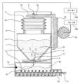
도 1은 화상 형성 장치의 일례를 도시하는 단면도이다.
도 2는, 도 1의 화상 형성 장치를 도시하는 사시도이다.
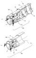
도 3은 현상제 보급 장치의 일 실시예를 도시하는 사시도이다.
도 4는, 도 3의 현상제 보급 장치를 다른 각도에서 본 사시도이다.
도 5는, 도 3의 현상제 보급 장치의 단면도이다.
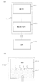
도 6은 제어 장치의 기능 구성을 도시하는 블록도이다.
도 7은 보급 동작의 흐름을 설명하는 흐름도이다.
도 8은 호퍼가 없는 현상제 보급 장치와 현상제 보급 용기의 장착 상태를 도시하는 단면도이다.
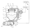
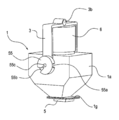
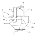
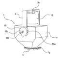
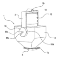
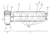
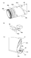
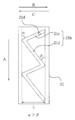
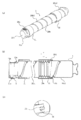
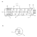
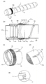
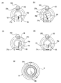
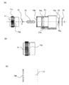
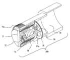
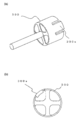
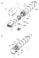
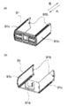
도 9의 (a), (b)는, 현상제 보급 용기의 일 실시예를 도시하는 사시도이다.
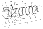
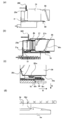
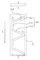
도 10은 현상제 보급 용기의 일 실시예를 도시하는 단면도이다.
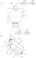
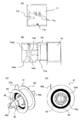
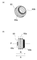
도 11의 (a)는, 유동성 에너지를 측정하는 장치에서 사용하는 블레이드의 사시도, (b)는 측정 장치의 모식도이다.
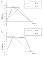
도 12의 (a)는, 배출구의 직경과 배출량의 관계를 나타낸 그래프, (b)는 용기 내의 충전량과 배출량의 관계를 나타낸 그래프이다.
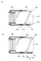
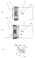
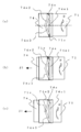
도 13의 (a)는, 현상제 보급 장치와 현상제 보급 용기를 도시하는 단면도, (b)는 로크 부재 주변의 확대도이다.
도 14의 (a)는, 현상제 보급 장치와 현상제 보급 용기를 도시하는 단면도, (b)는 로크 부재 주변의 확대도이다.
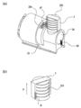
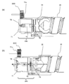
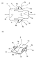
도 15는 현상제 보급 용기와 현상제 보급 장치의 동작 상태의 일부를 도시하는 사시도이다.
도 16은 현상제 보급 용기와 현상제 보급 장치의 동작 상태의 일부를 도시하는 사시도이다.
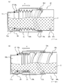
도 17은 현상제 보급 용기와 현상제 보급 장치를 도시하는 단면도이다.
도 18은 현상제 보급 용기와 현상제 보급 장치를 도시하는 단면도이다.
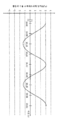
도 19는 실시예 1에 관한 현상제 수용부의 내압의 추이를 도시하는 도면이다.
도 20의 (a)는, 검증 실험에 사용한 현상제 보급 시스템(실시예 1)을 도시하는 블록도, (b)는 현상제 보급 용기 내에서 발생하는 현상을 도시하는 개략도이다.
도 21의 (a)는 검증 실험에 사용한 현상제 보급 시스템(비교예)을 도시하는 블록도, (b)는 현상제 보급 용기 내에서 발생하는 현상을 도시하는 개략도이다.
도 22의 (a), (b)는 현상제 보급 용기의 내압의 추이를 도시하는 도면이다.
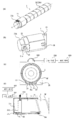
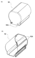
도 23은 실시예 2의 현상제 보급 용기를 도시하는 사시도이다.
도 24는 실시예 2의 현상제 보급 용기를 도시하는 단면도이다.
도 25는 실시예 3의 현상제 보급 용기를 도시하는 사시도이다.
도 26은 실시예 3의 현상제 보급 용기를 도시하는 사시도이다.
도 27은 실시예 3의 현상제 보급 용기를 도시하는 사시도이다.
도 28은 실시예 4의 현상제 보급 용기를 도시하는 사시도이다.
도 29는 실시예 4의 현상제 보급 용기를 도시하는 단면 사시도이다.
도 30은 실시예 4의 현상제 보급 용기를 도시하는 부분 단면도이다.
도 31은 실시예 4의 다른 실시 형태를 도시하는 단면도이다.
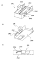
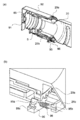
도 32는 실시예 5의 현상제 보급 장치를 나타내는, (a)는 장착부의 정면도, (b)는 장착부 내부의 부분 확대 사시도이다.
도 33의 (a)는 실시예 5에 관한 현상제 보급 용기를 도시하는 사시도, (b)는 배출구 주변의 모습을 도시하는 사시도, (c), (d)는 현상제 보급 용기를 현상제 보급 장치의 장착부에 장착한 상태를 도시하는 정면도 및 단면도이다.
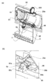
도 34의 (a)는 실시예 5에 관한 현상제 수용부를 나타내는 부분 사시도, (b)는 현상제 보급 용기를 도시하는 단면 사시도에서, (c)는 플랜지부의 내면을 도시하는 단면도이다. (d)는 현상제 보급 용기를 도시하는 단면도이다.
도 35의 (a)는 현상제 수납부를 나타내는 부분 사시도, (b)는 규제 부재를 도시하는 사시도, (c)는 규제 부재와 플랜지를 도시하는 사시도이다.
도 36의 (a)는 규제부에 의한 규제 상태를 도시하는 부분 단면도, (b)는 규제부에 의한 규제 해제 상태를 도시하는 부분 단면도이다.
도 37은 현상제 보급 장치에 대한 현상제 보급 용기의 장탈착 동작의 일부를 나타내며, (a), (b)는 부분 단면도, (c)는 부분 단면 확대도이다.
도 38은 현상제 보급 장치에 대한 현상제 보급 용기의 장탈착 동작의 일부를 나타내며, (a), (b)는 부분 단면도, (c), (d)는 부분 단면 확대도이다.
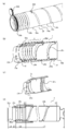
도 39의 (a), (b)는 현상제 보급 용기에서의 펌프부에 의한 흡기 및 배기 동작시의 모습을 도시하는 단면도이다.
도 40은 현상제 보급 용기의 캠 홈 형상을 나타내는 전개도이다.
도 41은 현상제 보급 용기의 캠 홈 형상의 일례를 나타내는 전개도이다.
도 42는 현상제 보급 용기의 캠 홈 형상의 일례를 나타내는 전개도이다.
도 43은 현상제 보급 용기의 캠 홈 형상의 일례를 나타내는 전개도이다.
도 44는 현상제 보급 용기의 캠 홈 형상의 일례를 나타내는 전개도이다.
도 45는 현상제 보급 용기의 캠 홈 형상의 일례를 나타내는 전개도이다.
도 46은 현상제 보급 용기의 캠 홈 형상의 일례를 나타내는 전개도이다.
도 47의 (a), (b)는 현상제 보급 용기의 내압 변화의 추이를 나타내는 그래프이다.
도 48의 (a), (b)는 현상제 보급 용기의 캠 홈 형상을 나타내는 전개도이다.
도 49는 실시예 5의 현상제 보급 용기의 변형예에 관하며, (a), (b)는 캠 홈 형상을 나타내는 전개도이다. (c)는 캠 홈 형상의 부분 단면 확대도이다.
도 50의 (a)는 실시예 6에 관한 현상제 보급 용기의 구성을 도시하는 사시도, (b)는 현상제 보급 용기의 구성을 도시하는 단면도, (c)는 규제 부재 주변을 도시하는 개략 사시도이다.
도 51의 (a)는 실시예 7에 관한 현상제 보급 용기의 구성을 도시하는 단면도, (b)는 규제 부재 주변을 도시하는 개략 사시도이다.
도 52의 (a)는 실시예 8에 관한 현상제 보급 용기의 구성을 도시하는 사시도, (b)는 현상제 보급 용기의 단면도, (c)는 캠 기어를 도시하는 사시도, (d)는 캠 기어의 회전 걸림부를 도시하는 부분 확대도, (e)는 규제 부재 주변을 도시하는 개략 사시도이다.
도 53의 (a)는 실시예 9에 관한 현상제 보급 용기의 구성을 도시하는 사시도, (b)는 현상제 보급 용기의 구성을 도시하는 단면도, (c)는 규제 부재 주변을 도시하는 개략 사시도이다.
도 54의 (a)는 실시예 10에 관한 현상제 보급 용기의 구성을 도시하는 사시도, (b)는 현상제 보급 용기의 구성을 도시하는 단면도, (c)는 규제 부재 주변을 도시하는 개략 사시도이다.
도 55의 (a) 내지 (d)는 구동 변환 기구의 동작을 도시하는 도면이다.
도 56의 (a)는 실시예 11에 관한 현상제 보급 용기의 구성을 도시하는 사시도, (b), (c)는 구동 변환 기구의 동작을 도시하는 도면, (d)는 규제 부재 주변을 도시하는 개략 사시도이다.
도 57의 (a)는 실시예 12에 관한 현상제 보급 용기의 구성을 도시하는 단면 사시도, (b), (c)는 펌프부에 의한 흡기 및 배기 동작의 모습을 도시하는 단면도이다.
도 58의 (a)는 실시예 12에 관한 현상제 보급 용기의 다른 예를 나타내는 사시도, (b)는 현상제 보급 용기의 커플링부를 도시하는 도면, (c)는 규제 부재 주변을 도시하는 개략 사시도이다.
도 59의 (a)는 실시예 13에 관한 현상제 보급 용기의 구성을 도시하는 단면 사시도, (b), (c)는 펌프부에 의한 흡기 및 배기 동작의 모습을 도시하는 단면도, (d)는 규제 부재 주변을 도시하는 개략 사시도이다.
도 60의 (a)는 실시예 14에 관한 현상제 보급 용기의 구성을 도시하는 사시도, (b)는 현상제 보급 용기의 구성을 도시하는 단면 사시도, (c)는 현상제 수용부 단부의 구성을 도시하는 도면, (d), (e)는 펌프부의 흡기 및 배기 동작시의 모습을 도시하는 도면, (f)는 펌프부의 규제부인 유지 부재 및 로크 부재 주변을 도시하는 개략 사시도이다.
도 61의 (a)는 실시예 15에 관한 현상제 보급 용기의 구성을 도시하는 사시도, (b)는 플랜지부의 구성을 도시하는 사시도, (c)는 원통부의 구성을 도시하는 사시도이다.
도 62의 (a), (b)는 실시예 15에 관한 현상제 보급 용기의 펌프부에 의한 흡기 및 배기 동작의 모습을 도시하는 단면도, (c), (d)는 규제부로서의 테이프 부재의 예를 나타내는 개략도이다.
도 63은 실시예 15에 관한 현상제 보급 용기의 펌프부의 구성을 도시하는 도면이다.
도 64의 (a), (b)는 실시예 16에 관한 현상제 보급 용기의 구성을 도시하는 개략 단면도, (c)는 본 실시예에 관한 현상제 보급 용기가 장착되는 현상제 보급 장치를 도시하는 개략도이다.
도 65의 (a), (b)는 실시예 17에 관한 현상제 보급 용기의 원통부 및 플랜지부를 도시하는 사시도이다.
도 66의 (a), (b)는 실시예 17에 관한 현상제 보급 용기의 부분 단면 사시도이다.
도 67은 실시예 17에 관한 펌프의 동작 상태와 회전 셔터의 개폐 타이밍의 관계를 나타내는 타임차트이다.
도 68의 (a)는 실시예 18에 관한 현상제 보급 용기를 나타내는 부분 단면 사시도, (b)는 규제 부재 주변을 도시하는 개략 사시도이다.
도 69의 (a) 내지 (c)는 실시예 18에 관한 펌프부의 동작 상태를 도시하는 부분 단면도이다.
도 70은 실시예 18에 관한 펌프의 동작 상태와 구획 밸브의 개폐 타이밍의 관계를 나타내는 타임차트이다.
도 71의 (a)는 실시예 19에 관한 현상제 보급 용기의 부분 사시도, (b)는 플랜지부의 사시도, (c)는 현상제 보급 용기의 단면도, (d)는 규제 부재 주변을 도시하는 개략 사시도이다.
도 72의 (a)는 실시예 20에 관한 현상제 보급 용기의 구성을 도시하는 사시도, (b)는 현상제 보급 용기의 단면 사시도이다.
도 73의 (a)는 실시예 20에 관한 현상제 보급 용기의 구성을 나타내는 부분 단면 사시도, (b)는 규제 부재 주변을 도시하는 개략 사시도이다.
도 74는 실시예 21에 관한 현상제 보급 용기의 사시도이다.
도 75는 현상제 수용부의 사시도이다.
도 76은 플랜지의 사시도이다.
도 77의 (a), (b)는 현상제 수용부가 구동원으로부터의 구동으로 회전하는 상황을 도시한 도면, (c), (d)는 현상제 수용부가 가압 부재의 작용에 의해 회전하는 상황을 도시한 도면, (e)는 현상제 수용부를 길이 방향에서 본 정면도이다.
도 78의 (a), (b)는 현상제 보급 용기의 현상제 배출 상황을 나타낸 단면도이다.
도 79는 현상제 보급 용기의 캠 홈 형상을 나타내는 전개도이다.
도 80의 (a)는 현상제 보급 용기의 사시 확대도, (b)는 펌프부의 사시 확대도이다.
도 81의 (a)는 실시예 22에 관한 현상제 보급 용기를 도시하는 단면 사시도, (b)는 펌프부를 도시하는 단면 사시도, (c)는 현상제 수용부를 도시하는 단면 사시도이다.
도 82의 (a)는 펌프부를 각각 회전축 방향으로 펼쳐서 각 구성 부품을 배치한 도, (b)는 내통의 구동 변환부의 상세도, (c)는 외통의 구동 변환 수용부의 상세도이다.
도 83의 (a) 내지 (c)는 펌프부의 원리를 설명하는 모식도이다.
도 84의 (a), (b)는 현상제 보급 용기의 현상제 배출 상황을 나타낸 단면도이다.
도 85는 현상제 보급 용기를 도시하는 사시도이다.
도 86은 실시예 23에 관한 장치 본체의 구동부의 (a)는 사시도, (b)는 정면도이다.
도 87의 (a)는 현상제 보급 용기를 나타내는 사시 단면도, (b)는 펌프부를 나타내는 사시 단면도이다.
도 88의 (a)는 내통을 도시하는 도면, (b)는 외통을 도시하는 도면, (c)는 축력 유닛을 도시하는 사시도, (d)는 축력 유닛을 도시하는 정면도이다.
도 89는 펌프부를 각각 회전축 방향으로 펼쳐서 각 구성 부품을 배치한 도이다.
도 90의 (a)는 펌프부의 수축 상태를 도시하는 부분 단면도, (b)는 펌프부의 확장 상태 초기를 도시하는 부분 단면도, (c)는 펌프부의 확장 상태를 도시하는 부분 단면도이다.
도 91은 구동 전달 수단에 대한 설명도이며, (a)는 현상제 보급 용기의 장착 전의 상태를 도시하는 부분 단면도, (b)는 현상제 보급 용기의 장착 완료 상태를 도시하는 부분 단면도이다.
도 92의 (a)는 펌프부의 수축 상태를 도시하는 부분 단면도, (b)는 펌프부의 확장 상태 초기를 도시하는 부분 단면도, (c)는 펌프부의 확장 상태를 도시하는 부분 단면도이다.
도 93의 (a)는 현상제 보급 용기의 분해 사시도, (b)는 현상제 보급 용기의 사시도이다.
도 94는 용기 본체의 사시도이다.
도 95의 (a)는 상측 플랜지부의 사시도(상면측), (b)는 상측 플랜지부의 사시도(하면측)이다.
도 96의 (a)는 하측 플랜지부의 사시도(상면측), (b)는 하측 플랜지부의 사시도(하면측), (c)는 하측 플랜지부의 정면도이다.
도 97의 (a)는 셔터의 상면도, (b)는 셔터의 사시도이다.
도 98의 (a)는 펌프의 사시도, (b)는 펌프의 정면도이다.
도 99의 (a)는 왕복 부재의 사시도(상면측), (b)는 왕복 부재의 사시도(하면측)이다.
도 100의 (a)는 커버의 사시도(상면측), (b)는 커버의 사시도(하면측)이다.
도 101의 (a)는 현상제 수용 장치의 부분 확대 사시도, (b)는 현상제 받침부의 사시도이다.
도 102의 (a)는 규제 상태에서의 현상제 보급 용기의 부분 확대 사시도, (b)는 규제 상태에서의 현상제 수용 장치의 부분 확대 사시도이다.
도 103의 (a)는 규제 해제 상태에서의 현상제 보급 용기와 현상제 보급 장치의 부분 확대 사시도, (b)는 규제 해제 상태에서의 현상제 보급 용기와 현상제 보급 장치의 부분 확대 사시도이다.1 is a sectional view showing an example of an image forming apparatus.
Fig. 2 is a perspective view showing the image forming apparatus of Fig. 1. Fig.
3 is a perspective view showing an embodiment of the developer dispensing apparatus.
Fig. 4 is a perspective view of the developer dispensing apparatus of Fig. 3 viewed from another angle. Fig.
5 is a cross-sectional view of the developer dispensing apparatus of Fig. 3;
6 is a block diagram showing a functional configuration of the control device.
7 is a flowchart for explaining the flow of the supply operation.
8 is a cross-sectional view showing the mounting state of the developer dispensing apparatus without the hopper and the developer dispensing container.
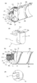
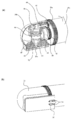
9 (a) and 9 (b) are perspective views showing one embodiment of a developer replenishing container.
10 is a cross-sectional view showing an embodiment of the developer replenishing container.
11 (a) is a perspective view of a blade used in an apparatus for measuring fluidity energy, and Fig. 11 (b) is a schematic view of a measuring apparatus.
FIG. 12A is a graph showing the relationship between the diameter of the discharge port and the discharge amount, and FIG. 12B is a graph showing the relationship between the filling amount and the discharge amount in the container.
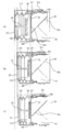
FIG. 13A is a cross-sectional view showing the developer dispensing apparatus and the developer dispensing container, and FIG. 13B is an enlarged view around the lock member.
Fig. 14 (a) is a cross-sectional view showing the developer dispensing apparatus and the developer dispensing container, and Fig. 14 (b) is an enlarged view around the lock member.
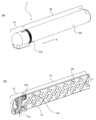
15 is a perspective view showing a part of the operation states of the developer replenishing container and the developer replenishing device.
16 is a perspective view showing a part of the operating state of the developer replenishing container and the developer replenishing device.
17 is a sectional view showing the developer replenishing container and the developer replenishing device.
18 is a sectional view showing the developer replenishing container and the developer replenishing device.
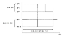
Fig. 19 is a diagram showing the change in internal pressure of the developer accommodating portion according to the first embodiment. Fig.
20 (a) is a block diagram showing a developer replenishing system (Example 1) used in a verification test, and (b) is a schematic diagram showing a phenomenon occurring in a developer replenishing container.
Fig. 21 (a) is a block diagram showing a developer replenishment system (comparative example) used in a verification test, and Fig. 21 (b) is a schematic view showing a phenomenon occurring in a developer replenishing container.
22 (a) and 22 (b) are diagrams showing the transition of the internal pressure of the developer replenishing container.
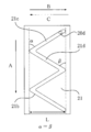
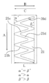
23 is a perspective view showing a developer replenishing container of
24 is a sectional view showing the developer replenishing container of the second embodiment.
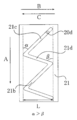
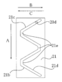
25 is a perspective view showing the developer replenishing container of Embodiment 3. Fig.
26 is a perspective view showing the developer replenishing container of Embodiment 3. Fig.
27 is a perspective view showing the developer replenishing container of Embodiment 3. Fig.
28 is a perspective view showing the developer replenishing container of
29 is a cross-sectional perspective view showing the developer replenishing container of
30 is a partial cross-sectional view showing the developer replenishing container of
31 is a cross-sectional view showing another embodiment of the fourth embodiment.
Fig. 32 is a front view of the mounting portion, and Fig. 32 (b) is a partially enlarged perspective view of the inside of the mounting portion, showing the developer dispensing apparatus of
FIG. 33A is a perspective view showing a developer replenishing container according to
FIG. 34A is a partial perspective view showing the developer accommodating portion according to
Fig. 35 (a) is a partial perspective view showing the developer storage portion, Fig. 35 (b) is a perspective view showing the regulating member, and Fig. 35 (c) is a perspective view showing the regulating member and the flange.
36 (a) is a partial cross-sectional view showing a regulating state by the regulating portion, and (b) is a partial cross-sectional view showing the regulating releasing state by the regulating portion.
37 is a partial cross-sectional view of the developer replenishing container for the developer replenishing device, in which (a), (b) are partial cross-sectional views, and FIG.
38 is a partial cross-sectional view of the developer replenishing container for the developer replenishing device, and Figs. 38A and 38B are partial cross-sectional enlarged views of the developer replenishing container.
39 (a) and 39 (b) are cross-sectional views showing a state in the intake and exhaust operation by the pump section in the developer replenishing container.
40 is a developed view showing the cam groove shape of the developer replenishing container.
41 is a developed view showing an example of the cam groove shape of the developer replenishing container.
42 is a development view showing an example of the cam groove shape of the developer replenishing container.
43 is a developed view showing an example of the cam groove shape of the developer replenishing container.
44 is a developed view showing an example of the cam groove shape of the developer replenishing container.
45 is a development view showing an example of the cam groove shape of the developer replenishing container.
46 is a development view showing an example of the cam groove shape of the developer replenishing container.
47 (a) and 47 (b) are graphs showing the change in the internal pressure of the developer replenishing container.
48 (a) and 48 (b) are development views showing the cam groove shape of the developer replenishing container.
Fig. 49 relates to a modification of the developer replenishing container according to the fifth embodiment, wherein (a) and (b) are development views showing cam groove shapes. (c) is a partial sectional enlarged view of the cam groove shape.
FIG. 50A is a perspective view showing the configuration of the developer replenishing container according to
51 (a) is a cross-sectional view showing a configuration of a developer replenishing container according to a seventh embodiment, and (b) is a schematic perspective view showing the periphery of the regulating member.
Fig. 52 (a) is a perspective view showing the construction of the developer replenishing container according to Example 8, Fig. 52 (b) is a sectional view of the developer replenishing container, (E) is a schematic perspective view showing the periphery of the regulating member. Fig.
FIG. 53A is a perspective view showing the configuration of the developer replenishing container according to
FIG. 54A is a perspective view showing the configuration of the developer replenishing container according to
55A to 55D are diagrams showing the operation of the drive conversion mechanism.
FIG. 56A is a perspective view showing the configuration of the developer replenishing container according to
Fig. 57 (a) is a cross-sectional perspective view showing the construction of the developer replenishing container according to the twelfth embodiment, and Figs. 57 (b) and (c) are cross-sectional views showing states of intake and exhaust operations by the pump section.
FIG. 58A is a perspective view showing another example of the developer replenishing container according to
FIG. 59A is a sectional perspective view showing the configuration of the developer replenishing container according to
Fig. 60 (a) is a perspective view showing the configuration of the developer replenishing container according to the fourteenth embodiment, and Fig. 60 (b) is a cross-sectional perspective view showing the configuration of the developer replenishing container, (F) is a schematic perspective view showing the surroundings of the holding member and the lock member which are the regulating portions of the pump portion. [Fig. 5] Fig.
FIG. 61 (a) is a perspective view showing a configuration of a developer replenishing container according to a fifteenth embodiment, (b) is a perspective view showing a configuration of a flange portion, and FIG. 61 (c) is a perspective view showing the configuration of a cylindrical portion.
Fig. 62 is a cross-sectional view showing a state of the intake and exhaust operation by the pump section of the developer replenishing container according to the fifteenth embodiment, and Figs. 62 (c) and (d) Fig.
63 is a diagram showing the configuration of the pump section of the developer replenishing container according to the fifteenth embodiment;
Fig. 64 is a schematic cross-sectional view showing the structure of the developer replenishing container according to the sixteenth embodiment, and Fig. 64 (c) is a view showing a developer replenishing device to which the developer replenishing container according to the present embodiment is mounted Fig.
65 (a) and 65 (b) are perspective views showing a cylindrical portion and a flange portion of the developer replenishing container according to the seventeenth embodiment.
66 (a) and 66 (b) are partial cross-sectional perspective views of a developer replenishing container according to a seventeenth embodiment.
67 is a time chart showing the relationship between the operation state of the pump according to the seventeenth embodiment and the opening / closing timing of the rotary shutter.
68 (a) is a partial cross-sectional perspective view showing a developer replenishing container according to Example 18, and (b) is a schematic perspective view showing the periphery of the regulating member.
69 (a) to 69 (c) are partial cross-sectional views showing the operation state of the pump section according to the eighteenth embodiment.
70 is a time chart showing the relationship between the operation state of the pump according to the eighteenth embodiment and the open / close timing of the partition valve.
FIG. 71A is a partial perspective view of the developer replenishing container according to the nineteenth example, FIG. 71B is a perspective view of the flange, FIG. 71C is a sectional view of the developer replenishing container, Fig.
Fig. 72 (a) is a perspective view showing a configuration of a developer replenishing container according to
FIG. 73 (a) is a fragmentary cross-sectional perspective view showing the construction of the developer replenishing container according to
74 is a perspective view of a developer replenishing container according to
75 is a perspective view of the developer accommodating portion;
76 is a perspective view of the flange.
Figs. 77 (a) and 77 (b) show a state in which the developer accommodating portion rotates by driving from the driving source, and Figs. 77 (c) and (d) show a state in which the developer accommodating portion rotates by the action of the urging member (E) is a front view of the developer accommodating portion viewed from the lengthwise direction.
78 (a) and 78 (b) are sectional views showing the developer discharge situation of the developer replenishing container.
79 is a development view showing the cam groove shape of the developer replenishing container.
80 (a) is an enlarged perspective view of the developer replenishing container, and FIG. 80 (b) is a diagonal enlarged view of the pump section.
Fig. 81A is a sectional perspective view showing the developer replenishing container according to Embodiment 22, Fig. 81B is a sectional perspective view showing the pump portion, and Fig. 81C is a sectional perspective view showing the developer containing portion.
Fig. 82 (a) is a view showing each component part arranged by extending the pump part in the direction of the rotational axis, (b) is a detailed view of the driving conversion part of the inner barrel, and Fig. 82 (c) is a detailed view of the drive conversion accommodating part of the outer barrel.
Figures 83 (a) to 83 (c) are schematic diagrams explaining the principle of the pump section.
Figures 84 (a) and 84 (b) are sectional views showing the developer discharging situation of the developer replenishing container.
85 is a perspective view showing the developer replenishing container.
FIG. 86 is a perspective view of the driving unit of the apparatus main body according to the twenty-third embodiment, and FIG. 86 is a front view thereof.
87 (a) is a perspective sectional view showing the developer replenishing container, and (b) is a perspective sectional view showing the pump section.
88 (a) is a view showing an inner cylinder, (b) is an outer cylinder, (c) is a perspective view showing an axial force unit, and (d) is a front view showing an axial force unit.
89 is a view in which the respective components are arranged by extending the pump section in the rotational axis direction.
Fig. 90 (a) is a partial cross-sectional view showing the shrinking state of the pump portion, Fig. 90 (b) is a partial cross-sectional view showing an initial state of expansion of the pump portion, and Fig.
Fig. 91 is an explanatory view of the drive transmitting means, Fig. 91 (a) is a partial sectional view showing a state before mounting the developer replenishing container, and Fig. 91 (b) is a partial sectional view showing the mounting state of the developer replenishing container.
Fig. 92 (a) is a partial cross-sectional view showing a contracted state of the pump portion, Fig. 92 (b) is a partial cross-sectional view showing an initial state of expansion of the pump portion, and Fig.
93 (a) is an exploded perspective view of the developer replenishing container, and (b) is a perspective view of the developer replenishing container.
94 is a perspective view of the container main body.
95 (a) is a perspective view (upper surface side) of the upper flange portion and (b) is a perspective view (lower surface side) of the upper flange portion.
96 (a) is a perspective view (upper surface side) of the lower flange portion, (b) is a perspective view of the lower flange portion (lower surface side), and FIG. 96 (c) is a front view of the lower flange portion.
97 (a) is a top view of the shutter, and Fig. 97 (b) is a perspective view of the shutter.
98 (a) is a perspective view of the pump, and (b) is a front view of the pump.
99 (a) is a perspective view (upper surface side) of the reciprocating member, and (b) is a perspective view (lower surface side) of the reciprocating member.
100 (a) is a perspective view (upper surface side) of the cover, and (b) is a perspective view (lower surface) of the cover.
101 (a) is a partially enlarged perspective view of the developer receiving apparatus, and FIG. 101 (b) is a perspective view of the developer receiving section.
Fig. 102 (a) is a partially enlarged perspective view of the developer replenishing container in the regulated state, and Fig. 102 (b) is a partially enlarged perspective view of the developer accommodating device in the regulated state.
Fig. 103 (a) is a partially enlarged perspective view of the developer replenishing container and the developer replenishing device in the restriction releasing state, and Fig. 103 (b) is a partially enlarged perspective view of the developer replenishing container and the developer replenishing device in the restriction releasing state.
이하, 본 발명에 따른 현상제 보급 용기 및 현상제 보급 시스템에 대하여 구체적으로 설명한다. 또한, 이하에서, 특별한 기재가 없는 한, 발명의 사상의 범위 내에서 현상제 보급 용기의 다양한 구성을 마찬가지의 기능을 발휘하는 공지된 다른 구성으로 치환하는 것이 가능하다. 즉, 특별한 기재가 없는 한, 후술하는 실시예에 기재된 현상제 보급 용기의 구성만으로 한정할 의도는 없다.Hereinafter, a developer replenishing container and a developer replenishing system according to the present invention will be described in detail. In the following, unless otherwise specified, various configurations of the developer replenishing container can be replaced with other known configurations that perform similar functions within the spirit of the invention. That is, the present invention is not limited to the configuration of the developer replenishing container described in the following embodiments, unless otherwise specified.
[실시예 1][Example 1]
우선, 화상 형성 장치의 기본 구성에 대하여 설명하고, 계속해서, 이 화상 형성 장치에 탑재되는 현상제 보급 시스템을 구성하는 현상제 보급 장치와 현상제 보급 용기의 구성에 대하여 순서대로 설명한다.First, the basic configuration of the image forming apparatus will be described, and then the configuration of the developer replenishing apparatus and the developer replenishing container constituting the developer replenishing system mounted in the image forming apparatus will be described in order.
(화상 형성 장치)(Image forming apparatus)
현상제 보급 용기(소위, 토너 카트리지)가 착탈 가능(제거 가능)하게 장착되는 현상제 보급 장치가 탑재된 화상 형성 장치의 일례로서, 전자 사진 방식을 채용한 복사기(전자 사진 화상 형성 장치)의 구성에 대하여 도 1을 사용하여 설명한다.An example of an image forming apparatus in which a developer replenishing container (so-called toner cartridge) is detachably (removably) mounted is provided. The image forming apparatus includes a copying machine (electrophotographic image forming apparatus) Will be described with reference to Fig.
동 도면에서, 100은 복사기 본체(이하, 화상 형성 장치 본체 또는 장치 본체라고 함)이다. 또한, 101은 원고이며, 원고대 유리(102) 위에 놓인다. 그리고, 원고의 화상 정보에 따른 광상을 광학부(103)의 복수의 미러(M)와 렌즈(Ln)에 의해, 전자 사진 감광체(104)(이하, 감광체) 상에 결상시킴으로써 정전 잠상을 형성한다. 이 정전 잠상은 건식의 현상기 (1성분 현상기)(201)에 의해 현상제(건식 분체)로서의 토너(1성분 자성 토너)를 사용하여 가시화된다.In the figure,
또한, 본 예에서는, 현상제 보급 용기(1)로부터 보급해야 할 현상제로서 1성분 자성 토너를 사용한 예에 대하여 설명하지만, 이러한 예뿐만 아니라, 후술하는 바와 같은 구성으로 해도 상관없다.In this example, an example in which a one-component magnetic toner is used as a developer to be supplied from the
구체적으로는, 1성분 비자성 토너를 사용하여 현상을 행하는 1성분 현상기를 사용하는 경우, 현상제로서 1성분 비자성 토너를 보급하게 된다. 또한, 자성 캐리어와 비자성 토너를 혼합한 2성분 현상제를 사용하여 현상을 행하는 2성분 현상기를 사용하는 경우, 현상제로서 비자성 토너를 보급하게 된다. 또한, 이 경우, 현상제로서 비자성 토너와 함께 자성 캐리어도 아울러 보급하는 구성으로 해도 상관없다.More specifically, in the case of using a one-component developing device that performs development using a one-component nonmagnetic toner, a one-component nonmagnetic toner is supplied as a developer. Further, in the case of using a two-component developing device that performs development using a two-component developer in which a magnetic carrier and a non-magnetic toner are mixed, a non-magnetic toner is supplied as a developer. Further, in this case, a configuration may be adopted in which a magnetic carrier is supplied in addition to the nonmagnetic toner as a developer.
참고 부호 105 내지 108은 기록 매체(이하, "시트"라고도 함)(S)를 수용하는 카세트이다. 이들 카세트(105 내지 108)에 적재된 시트(S) 중, 복사기의 액정 조작부로부터 조작자(유저)가 입력한 정보 또는 원고(101)의 시트 크기를 바탕으로 최적의 카세트가 선택된다. 여기서 기록 매체로는 용지에 한정되지 않고, 예를 들어 OHP 시트 등 적절히 사용, 선택할 수 있다.
그리고, 급송 분리 장치(105A 내지 108A)에 의해 반송된 1장의 시트(S)를, 반송부(109)를 경유하여 레지스트 롤러(110)까지 반송하고, 감광체(104)의 회전과, 광학부(103)의 스캔 타이밍을 동기시켜서 반송한다.One sheet S conveyed by the
참고 부호 111, 112는 전사 대전기, 분리 대전기이다. 여기서, 전사 대전기(111)에 의해, 감광체(104) 상에 형성된 현상제에 의한 상을 시트(S)에 전사한다. 그리고, 분리 대전기(112)에 의해, 현상제상(토너상)이 전사된 시트(S)를 감광체(104)로부터 분리한다.
그 후, 반송부(113)에 의해 반송된 시트(S)는, 정착부(114)에서 열과 압력에 의해 시트상의 현상제상을 정착시킨 후, 편면 카피인 경우에는, 배출 반전부(115)를 통과하여, 배출 롤러(116)에 의해 배출 트레이(117)에 배출된다.Thereafter, the sheet S conveyed by the conveying
또한, 양면 카피인 경우에는, 시트(S)는 배출 반전부(115)를 지나, 일단 배출 롤러(116)에 의해 일부가 장치 밖으로 배출된다. 그리고, 그 후, 시트(S)의 종단부가 플래퍼(118)를 통과하여, 배출 롤러(116)에 아직 끼워져 있는 타이밍에서 플래퍼(118)를 제어함과 함께 배출 롤러(116)를 역회전시킴으로써, 다시 장치 내로 반송된다. 또한, 그 후, 재급송 반송부(119, 120)를 경유하여 레지스트 롤러(110)까지 반송된 후, 편면 카피인 경우와 마찬가지의 경로를 거쳐 배출 트레이(117)에 배출된다.Further, in the case of a double-sided copy, the sheet S passes through the
상기 구성의 장치 본체(100)에 있어서, 감광체(104)의 주위에는 현상 수단으로서의 현상기(201), 클리닝 수단으로서의 클리너부(202), 대전 수단으로서의 1차 대전기(203) 등의 화상 형성 프로세스 기기가 설치되어 있다. 또한, 현상기(201)는 원고(101)의 화상 정보에 기초하여 광학부(103)에 의해 감광체(104)에 형성된 정전 잠상에 현상제를 부착시킴으로써 현상하는 것이다. 또한, 1차 대전기(203)는 감광체(104) 위에 원하는 정전 상을 형성하기 위해 감광체 표면을 균일하게 대전하기 위한 것이다. 또한, 클리너부(202)는 감광체(104)에 잔류하고 있는 현상제를 제거하기 위한 것이다.In the apparatus
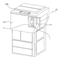
도 2는, 화상 형성 장치의 외관도이다. 화상 형성 장치의 외장 커버의 일부인 교환용 커버(40)를 조작자가 열면, 후술하는 현상제 보급 장치(8)의 일부가 나타난다.2 is an external view of the image forming apparatus. When the operator opens the
그리고, 이 현상제 보급 장치(8) 내에 현상제 보급 용기(1)를 삽입(장착)함으로써, 현상제 보급 용기(1)는 현상제 보급 장치(8)에 현상제를 보급 가능한 상태로 세팅된다. 한편, 조작자가 현상제 보급 용기(1)를 교환할 때는, 장착시와는 역으로 조작을 행함으로써 현상제 보급 장치(8)로부터 현상제 보급 용기(1)를 꺼내고(탈리하고), 새로운 현상제 보급 용기(1)를 다시 세팅하면 된다. 여기에서는, 교환용 커버(40)는 현상제 보급 용기(1)를 착탈(교환)하기 위한 전용 커버이며, 현상제 보급 용기(1)를 착탈하기 위해서만 개폐된다. 또한, 장치 본체(100)의 유지 보수는, 전방면 커버(100c)를 개폐함으로써 행해진다.The
(현상제 보급 장치)(Developer dispensing device)
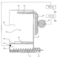
이어서, 현상제 보급 장치(8)에 대해서, 도 3, 도 4, 도 5를 사용하여 설명한다. 도 3은, 현상제 보급 장치(8)의 개략 사시도이다. 도 4는, 도 3의 이측에서 본 현상제 보급 장치(8)의 개략 사시도이다. 도 5는 현상제 보급 장치(8)의 개략 단면도이다.Next, the
현상제 보급 장치(8)에는, 현상제 보급 용기(1)가 제거 가능(착탈 가능)하게 장착되는 장착부(장착 스페이스)(8f)가 설치되어 있다. 또한, 후술하는 현상제 보급 용기(1)의 배출구(배출 구멍)(1c)로부터 배출된 현상제를 받아들이기 위한 현상제 수용구(현상제 수용 구멍)(8a)가 형성되어 있다. 또한, 현상제 수용구(8a)의 직경은, 장착부(8f) 내가 현상제에 의해 더럽혀지는 것을 가급적으로 방지할 목적으로, 현상제 보급 용기(1)의 배출구(1c)와 대략 동일하게 하는 것이 바람직하다. 현상제 수용구(8a)와 배출구(1c)의 직경이 동일하다면, 각각의 구의 내면 이외에 현상제가 부착되어 더럽혀지는 것을 방지할 수 있기 때문이다.The
본 예에서는, 현상제 수용구(8a)는 현상제 보급 용기(1)의 배출구(1c)에 맞춰서 미세구(핀 홀)로 되어 있으며, 약 φ2mm로 설정되어 있다.In this example, the
또한, 현상제 보급 용기(1)의 위치를 고정하기 위한 L자 형상의 위치 결정 가이드(유지 부재)(8b)가 설치되어 있고, 이 위치 결정 가이드(8b)에 의해 현상제 보급 용기(1)의 장착부(8f)에 대한 장착 방향이 화살표 A 방향으로 되도록 구성되어 있다. 또한, 현상제 보급 용기(1)의 장착부(8f)로부터의 제거 방향은, 화살표 A 방향과는 역방향이 된다.An L-shaped positioning guide (holding member) 8b for fixing the position of the
또한, 현상제 보급 장치(8)는, 그 하부에 현상제를 일시적으로 저류해 두는 호퍼(8g)가 설치되어 있다. 이 호퍼(8g) 내에는, 도 5에 도시하는 바와 같이 현상기(201)의 일부인 현상제 호퍼부(201a)에 현상제를 반송하기 위한 반송 스크류(11)와, 현상제 호퍼부(201a)와 연통된 개구(8e)가 형성되어 있다. 또한, 본 실시예에서 호퍼(8g)의 용적은 130cm3로 되어 있다.The
도 1에 도시하는 현상기(201)는, 상술한 바와 같이, 원고(101)의 화상 정보에 기초하여 감광체(104) 상에 형성된 정전 잠상을, 현상제를 사용하여 현상하는 것이다. 또한, 현상기(201)에는, 현상제 호퍼부(201a) 외에 현상 롤러(201f)가 설치되어 있다.The developing
이 현상제 호퍼부(201a)에는, 현상제 보급 용기(1)로부터 보급된 현상제를 교반하기 위한 교반 부재(201c)가 설치되어 있다. 그리고, 이 교반 부재(201c)에 의해 교반된 현상제는, 반송 부재(201d)에 의해 반송 부재(201e)측으로 보내진다.The
그리고, 반송 부재(201e, 201b)에 의해 순서대로 반송되어 온 현상제는, 현상 롤러(201f)에 담지되어, 최종적으로 감광체(104)에 공급된다.The developer that has been conveyed in order by the conveying
또한, 현상제 보급 장치(8)에는, 도 3, 도 4에 도시한 바와 같이, 후술하는 현상제 보급 용기(1)를 구동하는 구동 기구로서 기능하는 걸림 지지 부재(9)와 기어(10)를 갖고 있다.3 and 4, the
이 걸림 지지 부재(9)는, 현상제 보급 용기(1)가 현상제 보급 장치(8)의 장착부(8f)에 장착되었을 때에, 현상제 보급 용기(1)의 구동 입력부로서 기능하는 후술하는 유지 부재(3)와 걸어 지지하도록 구성되어 있다.When the
또한, 이 걸림 지지 부재(9)는, 현상제 보급 장치(8)의 장착부(8f)에 형성된 긴 구멍부(8c)에 헐겁게 끼워져 있으며, 장착부(8f)에 대하여 도면 중, 상하 방향으로 이동 가능한 구성으로 되어 있다. 또한, 이 걸림 지지 부재(9)는, 후술하는 현상제 보급 용기(1)의 유지 부재(3)(도 9 참조)와의 삽입성을 고려하여 그 선단에 테이퍼부(9d)가 설치되어 있고, 환봉 형상으로 되어 있다.The latching
또한, 이 걸림 지지 부재(9)의 걸림부(9a)(유지 부재(3)와 걸어 결합하는 결합 부위)는, 도 4에 도시하는 레일부(9b)에 연결되어 있고, 레일부(9b)는 현상제 보급 장치(8)의 가이드부(8d)에 그 양쪽 측단부가 유지되어, 도면 중, 상하 방향으로 이동 가능한 구성으로 되어 있다.The engaging
그리고, 레일부(9b)에는, 기어부(9c)가 설치되어 있고, 기어(10)와 걸림 결합되어 있다. 또한, 이 기어(10)는 구동 모터(500)와 연결되어 있다. 따라서, 화상 형성 장치(100)에 설치된 제어 장치(600)에 의해 구동 모터(500)의 회전 방향을 주기적으로 역회전시키는 제어를 행함으로써, 걸림 지지 부재(9)가 긴 구멍부(8c)를 따라, 도면 중, 상하 방향으로 왕복 이동하는 구성으로 되어 있다.A
또한, 상세한 것은 후술하겠지만, 현상제 보급 장치(8)로부터의 제거시에 현상제 보급 용기(1)에 설치된 로크 부재(55)를 회동시키기 위한 걸림 결합 돌기(8j)를 갖는다.Further, as will be described later in detail, it has a latching
(현상제 보급 장치에 의한 현상제 보급 제어)(Developer dispensing control by the developer dispensing apparatus)
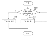
다음으로 현상제 보급 장치(8)에 의한 현상제 보급 제어에 대해서, 도 6, 도 7을 사용하여 설명한다. 도 6은 제어 장치(600)의 기능 구성을 도시하는 블록도이며, 도 7은 보급 동작의 흐름을 설명하는 흐름도이다.Next, the developer replenishment control by the
본 예에서는, 후술하는 현상제 보급 용기(1)의 흡기 동작에 수반하여 현상제 보급 장치(8)측에서 현상제 보급 용기(1) 내로 현상제가 역류하지 않도록, 호퍼(8g) 내에 일시적으로 저류되는 현상제의 양(제면의 높이)을 제한하고 있다. 따라서, 본 예에서는, 호퍼(8g) 내에 수용되어 있는 현상제의 양을 검출하는 현상제 센서(8k)(도 5 참조)를 설치하였다. 그리고, 도 6에 도시한 바와 같이, 그 현상제 센서(8k)의 출력에 따라서 제어 장치(600)가 구동 모터(500)를 작동/비작동의 제어를 행함으로써, 호퍼(8g) 내에 일정량 이상의 현상제가 수용되지 않도록 구성하고 있다. 그 제어 플로우에 대하여 설명한다. 우선 도 7에 도시한 바와 같이, 현상제 센서(8k)가 호퍼(8g) 내의 현상제 잔량을 체크한다(S100). 그리고, 현상제 센서(8k)에 의해 검출된 현상제 수용량이 소정 미만이라고 판정된 경우, 즉 현상제 센서(8k)에 의해 현상제가 검출되지 않은 경우, 구동 모터(500)를 구동하여 일정 시간 현상제의 보급을 실행한다(S101).In this example, the developer is temporarily stored in the
그 결과, 현상제 센서(8k)에 의해 검출된 현상제 수용량이 소정량에 달했다고 판정된 경우, 즉 현상제 센서(8k)에 의해 현상제가 검출된 경우, 구동 모터(500)의 구동을 오프하여, 현상제의 보급 동작을 정지한다(S102). 이 보급 동작의 정지에 의해, 일련의 현상제 보급 공정이 종료된다.As a result, when it is determined that the amount of the developer detected by the
이러한 현상제 보급 공정은, 화상 형성에 수반하여 현상제가 소비되어 호퍼(8g) 내의 현상제 수용량이 소정량 미만으로 되면, 반복해서 실행되는 구성으로 되어 있다.This developer replenishing step is configured to be repeatedly executed when the amount of developer in the
또한, 본 예에서는, 현상제 보급 용기(1)로부터 배출된 현상제를, 호퍼(8g) 내에 일시적으로 저류하고, 그 후, 현상기(201)에 보급하는 구성으로 하고 있지만, 이하와 같은 현상제 보급 장치의 구성으로 해도 상관없다.In the present embodiment, the developer discharged from the
특히 장치 본체(100)가 저속기인 경우에는, 본체의 콤팩트화, 저비용화가 요구된다. 이 경우, 도 8에 도시한 바와 같이 현상제 보급 용기(1)로부터 현상제를 직접 현상기(201)에 보급하는 구성이 바람직하다. 구체적으로는, 상술한 호퍼(8g)를 생략하고, 현상제 보급 용기(1)로부터 현상기(201)에 직접 현상제를 보급하는 구성이다. 이 도 8은, 현상제 보급 장치로서 2성분 현상기(201)를 사용한 예이다. 이 현상기(201)에는, 현상제가 보급되는 교반실과 현상 롤러(201f)에 현상제를 공급하는 현상실을 갖고 있으며, 교반실과 현상실에는 현상제 반송 방향이 서로 역방향이 되는 반송 부재(스크류)(201d)가 설치되어 있다. 그리고, 교반실과 현상실은 길이 방향 양단부에서 서로 연통되어 있고, 2성분 현상제는 이들 2개의 방을 순환 반송되는 구성으로 되어 있다. 또한, 교반실에는 현상제 중의 토너 농도를 검출하는 자기 센서(201g)가 설치되어 있어, 이 자기 센서(201g)의 검출 결과에 기초하여 제어 장치(600)가 구동 모터(500)의 동작을 제어하는 구성으로 되어 있다. 이 구성의 경우, 현상제 보급 용기(1)로부터 보급되는 현상제는, 비자성 토너, 또는 비자성 토너 및 자성 캐리어가 된다.Particularly, when the apparatus
본 예에서는, 후술하는 바와 같이, 현상제 보급 용기(1) 내의 현상제는 배출구(1c)로부터 중력 작용만으로는 거의 배출되지 않고, 펌프부(2)에 의한 배기 동작에 의해 현상제가 배출되기 때문에, 배출량의 변동을 억제할 수 있다. 그로 인해, 호퍼(8g)를 생략한 도 8과 같은 예에서도, 마찬가지로, 후술하는 현상제 보급 용기(1)의 적용이 가능하다.In this embodiment, as described later, the developer in the
(현상제 보급 용기)(Developer supply container)
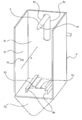
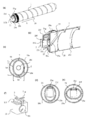
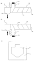
이어서, 본 실시예에 관한 현상제 보급 용기(1)에 대해서, 도 9, 도 10을 사용하여 설명한다. 도 9의 (a)는 현상제 보급 용기(1)의 개략 사시도, 도 9의 (b)는 현상제 보급 용기(1)의 로크 부재(55)를 떼어낸 모습을 나타내는 사시 분해도이다. 또한, 도 10은 현상제 보급 용기(1)의 개략 단면도이다.Next, the
도 9에 도시한 바와 같이, 현상제 보급 용기(1)는, 현상제를 수용하는 현상제 수용부로서 기능하는 용기 본체(1a)를 갖고 있다. 또한, 도 10에 도시하는 (1b)는, 용기 본체(1a) 내의 현상제가 수용되는 현상제 수용 스페이스를 나타내고 있다. 즉, 본 예에서는, 현상제 수용부로서 기능하는 현상제 수용 스페이스(1b)는, 용기 본체(1a)와 후술하는 펌프부(2)의 내부 스페이스를 합한 것이 된다. 본 예에서는, 체적 평균 입경이 5㎛ 내지 6㎛인 건식 분체인 1성분 토너가 현상제 수용 스페이스(1b)에 수용되어 있다.As shown in Fig. 9, the
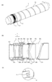
또한, 본 예에서는, 펌프부로서, 그 용적이 가변인 용적 가변형 펌프부(2)를 채용하고 있다. 구체적으로는, 펌프부(2)로서, 현상제 보급 장치(8)로부터 받은 구동력에 의해 신축 가능한 주름 상자 형상의 신축부(주름 상자부, 신축 부재)(2a)가 설치된 것을 채용하고 있다. 이 펌프부(2)의 신축부(2a)는, 용적을 증감시킴으로써 상기 용기 본체(1a)의 내압을 변화시키는 용적 가변부이다.In this embodiment, the volume variable
본 예의 주름 상자 형상의 펌프부(2)는 도 9, 도 10에 도시한 바와 같이, "바깥 접기"부와 "안쪽 접기"부가 주기적으로 교대로 형성되어 있고, 그 접힌 선을 따라(그 접힌 선을 기점으로 해서) 접히거나 펼쳐질 수 있다. 따라서, 본 예와 같이, 주름 상자 형상의 펌프부(2)를 채용한 경우, 신축량에 대한 용적 변화량의 편차를 적게 할 수 있으므로, 안정적인 용적 가변 동작을 행하는 것이 가능하게 된다.As shown in Figs. 9 and 10, the bellows-shaped
여기서 본 실시예에서는, 현상제 수용 스페이스(1b)의 전체 용적은 480cm3이며, 그 중, 펌프부(2)의 용적은 160cm3(신축부(2a)가 자연 길이일 때)이고, 본 예에서는 펌프부(2)를 자연 길이로부터 신장하는 방향으로 펌핑 동작을 행하는 설정으로 되어 있다.In this embodiment, the total volume of the
또한, 펌프부(2)의 신축부(2a)의 신축에 의한 용적 변화량은 15cm3이며, 펌프부(2)의 최대 신장시의 전체 용적은 495cm3로 설정되어 있다.The amount of change in volume due to the expansion and contraction of the
또한, 현상제 보급 용기(1)에는, 240g의 현상제가 충전되어 있다.The developing
또한, 걸림 지지 부재(9)를 구동하는 구동 모터(500)를 제어 장치(600)가 제어함으로써, 용적 변화 속도가 90cm3/s이 되도록 설정되어 있다. 또한, 용적 변화량, 용적 변화 속도는 현상제 보급 장치(8)측으로부터의 요구 배출량을 감안하여 적절히 설정할 수 있다.Further, the
또한, 본 예의 펌프부(2)는 주름 상자 형상의 것을 채용하고 있지만, 현상제 수용 스페이스(1b) 내의 공기량(압력)을 변화시킬 수 있는 펌프이면, 다른 구성이어도 상관없다. 예를 들어, 펌프부(2)로서, 1축 편심 스크루 펌프를 사용하는 구성이어도 상관없다. 이 경우, 1축 편심 스크루 펌프에 의한 흡기 및 배기를 행하기 위한 개구가 별도 필요해지고, 그 개구로부터 현상제가 누출되어버리는 것을 방지하기 위한 필터 등의 기구가 필요하게 된다. 또한 1축 편심 스크루 펌프를 구동하기 위한 토크가 매우 높으므로, 화상 형성 장치 본체(100)에 대한 부하가 증대한다. 따라서, 이러한 폐해가 없는, 주름 상자 형상의 펌프가 보다 바람직하다.The
또한, 현상제 수용 스페이스(1b)가 펌프부(2)의 내부 공간만으로 되는 구성이어도 전혀 상관없다. 즉, 이 경우, 펌프부(2)가 현상제 수용 스페이스(1b)로서의 기능도 동시에 완수하게 된다.The configuration may also be such that the
또한, 펌프부(2)의 접합부(2b)와 용기 본체(1a)의 피접합부(1i)가 열 용착에 의해 일체화되어 있고, 여기로부터 현상제가 누설되지 않도록 현상제 수용 스페이스(1b)의 기밀성이 유지되게 구성되어 있다.The sealing
또한, 현상제 보급 용기(1)에는, 현상제 보급 장치(8)의 구동 기구와 걸림 결합 가능하게 설치되고, 이 구동 기구로부터 펌프부(2)를 구동하기 위한 구동력이 입력되는 구동 입력부(구동 수용부, 구동 연결부, 걸림부)로서, 후술하는 유지 부재(3)에 일체로 설치된 피결합부(3b)가 설치되어 있다.The
구체적으로는, 현상제 보급 장치(8)의 걸림 지지 부재(9)와 걸림 지지 가능한 피결합부(3b)는 펌프부(2)의 상단부에 설치되어 있다. 현상제 보급 용기(1)가 장착부(8f)(도 3 참조)에 장착되었을 때에 이 피결합부(3b)에 걸림 지지 부재(9)가 삽입됨으로써, 양자가 실질적으로 일체화된다(삽입성을 고려하여 약간 덜걱거림이 있음). 이에 의해, 도 9에 도시한 바와 같이, 신축부(2a)의 신축 방향인 화살표 p 방향, 화살표 q 방향에 대하여 피결합부(3b)와 걸림 지지 부재(9)의 상대 위치가 고정된다. 또한, 펌프부(2)과 피결합부(3b)는, 예를 들어 사출 성형법이나 블로우 성형법 등을 사용하여 일체 형성된 것을 사용하는 것이 보다 바람직하다.More specifically, the engaging
이와 같이 하여 걸림 지지 부재(9)와 실질적으로 일체화된 피결합부(3b)는, 걸림 지지 부재(9)로부터 펌프부(2)의 신축부(2a)를 신축시키기 위한 구동력이 입력된다. 그 결과, 걸림 지지 부재(9)의 상하 이동에 수반하여, 이것에 추종해서 펌프부(2)의 신축부(2a)를 신축시키는 것이 가능하게 된다.The driving force for stretching and contracting the stretchable and
즉, 펌프부(2)는, 구동 입력부로서 기능하는 피결합부(3b)가 받은 구동력에 의해 배출구(1c)를 통해 현상제 보급 용기의 내부를 향하는 기류와 현상제 보급 용기로부터 외부를 향하는 기류를 교대로 반복해서 발생시키는 기류 발생 기구로서 기능한다.That is, the
또한, 본 예에서는, 환봉 형상이 되는 걸림 지지 부재(9)와 둥근 구멍 형상이 되는 피결합부(3b)를 사용하여 양자를 실질적으로 일체화시키는 예로 하고 있지만, 신축부(2a)의 신축 방향(화살표 p 방향, 화살표 q 방향)에 대하여 서로의 상대 위치를 고정할 수 있으면, 다른 구조로 해도 상관없다. 예를 들어, 피결합부(3b)를 막대 형상 부재로 하면서 걸림 지지 부재(9)를 걸림 지지 구멍으로 하는 예나, 피결합부(3b)와 걸림 지지 부재(9)의 단면 형상을, 삼각형이나 사각형 등의 다각형이나, 타원이나 별 모양 등 그 밖의 형상으로 하는 것도 가능하다. 또는, 종래 공지의 다른 걸림 지지 구성을 채용해도 상관없다.In this embodiment, the engaging
또한, 용기 본체(1a)의 하단부의 플랜지부(1g)에는, 현상제 수용 스페이스(1b)에 있는 현상제의 현상제 보급 용기(1) 밖으로의 배출을 허용하는 배출구(1c)가 형성되어 있다. 배출구(1c)에 대해서는 상세를 후술한다.An
또한, 도 10에 도시한 바와 같이, 용기 본체(1a)의 하부는 배출구(1c)를 향해 경사면(1f)이 형성되어 있고, 현상제 수용 스페이스(1b)에 수용된 현상제는 중력에 의해 경사면(1f)을 미끄러져 떨어져서 배출구(1c) 근방에 모이는 형상으로 되어 있다. 본 예에서는, 이 경사면(1f)의 경사 각도(현상제 보급 용기(1)가 현상제 보급 장치(8)에 세팅된 상태에서의 수평면과의 이루는 각도)는, 현상제인 토너의 안식각(angle of repose)보다 큰 각도로 설정되어 있다.10, the lower portion of the container
또한, 현상제 보급 용기(1)는, 배출구(1c)만이 현상제 보급 용기(1) 외부와 연통되어 있어, 배출구(1c)를 제외하면 실질적으로 밀폐되어 있다.In the
이어서, 배출구(1c)를 개폐하는 셔터 기구에 대하여 도 3, 도 10을 사용하여 설명한다.Next, a shutter mechanism for opening and closing the
현상제 보급 용기(1)를 수송할 때의 현상제 누설을 방지하기 위해서, 배출구(1c)의 주위를 둘러싸도록 탄성체로 형성된 시일 부재(4)가 플랜지부(1g)의 하면에 접착, 고정되어 있다. 이 시일 부재(4)가 플랜지부(1g)의 하면과의 사이에서 압축되도록, 배출구(1c)를 밀폐하기 위한 셔터(5)가 설치되어 있다. 이 셔터(5)는, 가압 부재인 스프링(도시하지 않음)에 의해 폐쇄 방향으로 항상 가압된 상태(스프링의 신장력으로 가압)에 있다.A
이 셔터(5)는, 현상제 보급 용기(1)를 장착하는 동작에 연동하여, 현상제 보급 장치(8)에 형성된 맞닿음부(8h)(도 3 참조)의 단부면에 맞닿음으로써, 스프링이 줄어들어, 개봉이 행해지도록 구성되어 있다. 이때, 현상제 보급 용기(1)의 플랜지부(1g)가, 현상제 보급 장치(8)측의 위치 결정 가이드(8b)와 맞닿음부(8h)의 사이에 삽입되고, 현상제 보급 용기(1)의 측면(1k)(도 9 참조)이 현상제 보급 장치(8)의 스토퍼부(8i)(도 3 참조)에 접촉한다. 그 결과, 현상제 보급 용기(1)의 현상제 보급 장치(8)에 대한 장착 방향(화살표 A 방향)의 위치가 정해진다(도 17 참조).The
이와 같이, 플랜지부(1g)가 위치 결정 가이드(8b)에 가이드되면서 현상제 보급 용기(1)의 삽입 동작이 완료된 시점에서, 배출구(1c)와 현상제 수용구(8a)의 위치가 합치된다.As described above, when the
또한, 현상제 보급 용기(1)의 삽입 동작이 완료된 시점에서, 배출구(1c)와 수용구(8a)의 사이는 시일 부재(4)(도 17 참조)에 의해, 외부로 현상제가 누설되지 않도록 시일된다.At the time when the inserting operation of the
그리고, 현상제 보급 용기(1)의 삽입 동작에 수반해서, 현상제 보급 용기(1)의 유지 부재(3)의 피결합부(3b)에 걸림 지지 부재(9)가 삽입되어, 양자가 일체화된다.With the inserting operation of the
또한, 이때, 현상제 보급 용기(1)의 현상제 보급 장치(8)에 대한 장착 방향(화살표 A 방향)과 직교하는 방향(도 3에서 상하 방향)의 위치도 위치 결정 가이드(8b)의 L자부로 의해 결정된다. 즉, 위치 결정부로서의 플랜지부(1g)는 현상제 보급 용기(1)가 상하 방향(펌프부(2)의 왕복 이동 방향)으로 움직여버리는 것을 방지하는 역할도 하고 있다.At this time, the position of the
여기까지가, 현상제 보급 용기(1)의 일련의 장착 공정이 된다. 즉, 조작자가 교환용 커버(40)를 닫음으로써 장착 공정이 완료된다.Up to this point, a series of mounting process of the
또한, 현상제 보급 장치(8)로부터의 현상제 보급 용기(1)의 제거 공정은, 상술한 장착 공정과는 역의 수순으로 조작을 행하면 된다.In addition, the removing process of the
구체적으로는, 교환용 커버(40)를 열고, 현상제 보급 용기(1)를 장착부(8f)로부터 꺼내면 된다. 이때, 맞닿음부(8h)에 의한 간섭 상태가 해제됨으로써, 스프링(도시하지 않음)에 의해 셔터(5)가 폐쇄된다.More specifically, the
또한, 본 예에서는, 용기 본체(1a)(현상제 수용 스페이스(1b))의 내압을, 대기압(외기압)보다 낮게 한 상태(감압 상태, 부압 상태)와, 대기압보다 높게 한 상태(가압 상태, 정압 상태)로 소정의 주기로 교대로 반복해서 변화시키고 있다. 여기서 대기압(외기압)은, 현상제 보급 용기(1)가 설치된 환경에서의 것이다. 이와 같이, 용기 본체(1a)의 내압을 변화시킴으로써, 배출구(1c)로부터 현상제를 배출시키는 구성으로 되어 있다. 본 예에서는, 480cm3 내지 495cm3의 사이를 약 0.3초의 주기로 변화(왕복 이동)시키는 구성으로 되어 있다.In this example, the inner pressure of the container
용기 본체(1a)의 재질로는, 내압의 변화에 대해 크게 찌그러져버리거나, 크게 부풀어 오르지 않을 정도의 강성을 가진 것을 채용하는 것이 바람직하다.As the material of the container
따라서, 본 예에서는, 용기 본체(1a)의 재질로서 폴리스티렌 수지를 채용하고, 펌프부(2)의 재질로서 폴리프로필렌 수지를 사용하고 있다.Therefore, in this embodiment, the
또한, 사용하는 재질에 대해서, 용기 본체(1a)는 압력에 견딜 수 있는 소재이면, 예를 들어 ABS(아크릴로니트릴·부타디엔·스티렌 공중합체), 폴리에스테르, 폴리에틸렌, 폴리프로필렌 등의 수지를 사용하는 것이 가능하다. 또한, 금속제이어도 상관없다.As for the materials to be used, if the
또한, 펌프부(2)의 재질에 관해서는, 신축 기능을 발휘해서 용적 변화에 따라 현상제 수용 스페이스(1b)의 내압을 변화시킬 수 있는 전제의 재료이면 된다. 예를 들어, ABS(아크릴로니트릴·부타디엔·스티렌 공중합체), 폴리스티렌, 폴리에스테르, 폴리에틸렌 등을 얇게 형성한 것이라도 상관없다. 또한, 고무나, 그 밖의 신축성 재료 등을 사용하는 것도 가능하다.The material of the
또한, 수지 재료의 두께를 조정하거나 해서, 용기 본체(1a), 펌프부(2) 각각이 상술한 기능을 만족하는 것이라면, 용기 본체(1a)와 펌프부(2)를 동일한 재질로, 예를 들어 사출 성형법이나 블로우 성형법 등을 사용하여 일체적으로 성형된 것을 사용해도 상관없다.If the
또한, 본 예에서는, 현상제 보급 용기(1)는, 외부와는 배출구(1c)를 통해서만 연통되어 있어, 배출구(1c)를 제외하고는 외부로부터 실질적으로 밀폐된 구성으로 하고 있다. 즉, 펌프부(2)에 의해 현상제 보급 용기(1)의 내압을 가압, 감압시켜서 배출구(1c)로부터 현상제를 배출하는 구성을 채용하고 있으므로, 안정적인 배출 성능이 유지될 정도의 기밀성이 요구된다.In this example, the
한편, 현상제 보급 용기(1)를 운반할(특히, 공수(空輸)) 때나 장기간 보존할 때에, 환경의 급격한 변동에 따라 용기의 내압이 급격하게 변동해버릴 우려가 있다. 예를 들어, 표고가 높은 지역에서 사용하는 경우나, 기온이 낮은 장소에 보관되어 있었던 현상제 보급 용기(1)를 기온이 높은 실내로 가져와 사용하는 경우 등, 현상제 보급 용기(1)의 내압이 대기압에 대해 가압 상태로 되어버릴 우려가 있다. 이러한 사태가 되면, 용기가 변형되거나, 개봉시에 현상제가 분출되어버리는 등의 문제가 발생할 수 있다.On the other hand, when the
따라서, 본 예에서는, 그 대책으로서, 현상제 보급 용기(1)에 직경(φ)이 3mm인 개구를 형성하여, 이 개구에 필터를 설치하였다. 필터로는, 외부로의 현상제 누설은 방지하면서 용기 내외의 통기를 허용하는 특성을 구비한, 닛토덴코 가부시키가이샤 제조의 TEMISH(등록 상표명)를 사용하였다. 또한, 본 예에서는, 이러한 대책을 실시하고는 있지만, 펌프부(2)에 의한 배출구(1c)를 통한 흡기 동작 및 배기 동작에 대한 영향은 무시할 수 있어, 사실상, 현상제 보급 용기(1)의 기밀성은 유지되어 있다고 할 수 있다.Therefore, in this example, as countermeasures, an opening having a diameter of 3 mm is formed in the
(현상제 보급 용기의 배출구에 대해서)(With respect to the outlet of the developer supply container)
본 예에서는, 현상제 보급 용기(1)의 배출구(1c)에 대해서, 현상제 보급 용기(1)가 현상제 보급 장치(8)에 현상제를 보급하는 자세일 때, 중력 작용만으로는 충분히 배출되지 않을 정도의 크기로 설정하고 있다. 즉, 배출구(1c)의 개구 크기는, 중력 작용만으로는 현상제 보급 용기로부터 현상제의 배출이 불충분해질 정도로 작게 설정하고 있다(미세구(핀 홀)라고도 함). 바꾸어 말하면, 배출구(1c)가 현상제로 실질적으로 폐색되도록 그 개구의 크기를 설정하고 있다. 이에 의해, (1) 배출구(1c)로부터 현상제가 누설되기 어려워지고, (2) 배출구(1c)를 개방했을 때의 현상제의 과잉 배출을 억제할 수 있고, (3) 현상제의 배출을 펌프부에 의한 배기 동작에 지배적으로 의존시킬 수 있는 효과를 기대할 수 있다.In this example, with respect to the
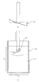
따라서, 본 발명자들은, 중력 작용만으로 충분히 배출되지 않는 배출구(1c)를 어느 정도의 크기로 설정할 것인가에 대해 검증 실험을 행하였다. 이하, 그 검증 실험(측정 방법)과 그 판단 기준을 이하에 설명한다.Therefore, the inventors of the present invention conducted a verification experiment to determine the size of the
저부 중앙에 배출구(원 형상)가 형성된 소정 용적의 직육면체 용기를 준비하고, 용기 내에 현상제를 200g 충전한 후, 충전구를 밀폐하여 배출구를 막은 상태에서 용기를 잘 흔들어서 현상제를 충분히 푼다. 이 직육면체 용기는, 용적이 약 1000cm3, 크기는, 세로 90mm×가로 92mm×높이 120mm로 되어 있다.A rectangular parallelepiped container having a predetermined volume in which a discharge port (circular shape) is formed at the center of the bottom is prepared. 200 g of the developer is filled in the container, and the developer is sufficiently loosened by shaking the container while sealing the charging port and closing the discharge port. This rectangular parallelepiped container has a volume of about 1000 cm 3 and a size of 90 mm in length × 92 mm in width × 120 mm in height.
그 후, 가급적 빠르게 배출구를 연직 하방을 향한 상태에서 배출구를 개봉하여, 배출구로부터 배출된 현상제의 양을 측정한다. 이때, 이 직육면체 용기는, 배출구 이외는 완전히 밀폐된 상태로 한다. 또한, 검증 실험은 온도 24℃, 상대 습도 55%의 환경하에서 행하였다.Thereafter, the discharge port is opened as quickly as possible with the discharge port facing downward, and the amount of the developer discharged from the discharge port is measured. At this time, this rectangular parallelepiped container is to be completely sealed except for the discharge port. In addition, the verification test was carried out in an environment of a temperature of 24 캜 and a relative humidity of 55%.
상기 수순에서, 현상제의 종류와 배출구의 크기를 바꾸어서 배출량을 측정한다. 또한, 본 예에서는, 배출된 현상제의 양이 2g 이하인 경우, 그 양은 무시할 수 있는 수준이며, 그 배출구가 중력 작용만으로는 충분히 배출되지 않는 크기라고 판단하였다.In the above procedure, the discharge amount is measured by changing the type of the developer and the size of the discharge port. Further, in this example, when the amount of discharged developer is 2 g or less, the amount is negligible, and it is judged that the outlet is not sufficiently discharged by gravity alone.
검증 실험에 사용한 현상제를 표 1에 나타내었다. 현상제의 종류는, 1성분 자성 토너, 2성분 현상기에 사용되는 2성분 비자성 토너, 2성분 현상기에 사용되는 2성분 비자성 토너와 자성 캐리어의 혼합물이다.Table 1 shows the developer used in the verification test. The developer is a mixture of a one-component magnetic toner, a two-component nonmagnetic toner used in a two-component developer, and a two-component nonmagnetic toner and a magnetic carrier used in a two-component developer.
이들 현상제의 특성을 표현하는 물성 값으로서, 유동성을 나타내는 안식각 이외에, 분체 유동성 분석 장치(Freeman Technology사제 파우더 레오미터 FT4)에 의해, 현상제층의 풀어짐성을 나타내는 유동성 에너지에 대하여 측정하였다.As a property value expressing the properties of these developers, fluidity energy indicating the solubility of the developer layer was measured by a powder fluidity analyzer (Powder Rheometer FT4 manufactured by Freeman Technology) in addition to the angle of repose showing fluidity.

이 유동성 에너지의 측정 방법에 대해 도 11을 사용하여 설명한다. 여기서 도 11은 유동성 에너지를 측정하는 장치의 모식도이다.This fluid energy measurement method will be described with reference to FIG. 11 is a schematic diagram of a device for measuring fluidity energy.
이 분체 유동성 분석 장치의 원리는, 분체 샘플 중에서 블레이드를 이동시켜, 그 블레이드가 분체 중을 이동하는데 필요한 유동성 에너지를 측정하는 것이다. 블레이드는 프로펠러형으로, 회전하는 동시에 회전축 방향으로도 이동하기 때문에 블레이드의 선단은 나선을 그리게 된다.The principle of this fluidity fluidity analyzer is to move the blades in the powder sample and measure the fluidity energy required for the blades to travel through the powder. Since the blade is propeller type, it also rotates and moves in the direction of the axis of rotation, so that the tip of the blade draws a spiral.
프로펠러형의 블레이드(51)(이하, 블레이드라고 함)로서, 직경이 48mm이고, 반시계 방향으로 매끄럽게 비틀린 SUS제의 블레이드(형식 번호: C210)를 사용하였다. 상세하게는, 48mm×10mm의 블레이드판의 중심에 블레이드판의 회전면에 대하여 법선 방향으로 회전축이 존재하고, 블레이드판의 양쪽 최외측 테두리부(회전축에서 24mm 부분)의 비틀림각이 70°, 회전축에서 12mm 부분의 비틀림각이 35°로 되어 있다.As the propeller type blade 51 (hereinafter referred to as a blade), a SUS blade (model number: C210) having a diameter of 48 mm and twisted in a counterclockwise direction was used. Specifically, a rotation axis is present in the normal direction with respect to the rotation plane of the blade plate at the center of the blade plate of 48 mm x 10 mm, the twist angle of the outermost rims (24 mm portion from the rotation axis) of the blade plate is 70 degrees, The twist angle of the 12 mm portion is 35 degrees.
유동성 에너지란, 분체층 중에 상술한 바와 같이 나선 형상으로 회전하는 블레이드(51)를 침입시켜, 블레이드가 분체층 중을 이동할 때에 얻어지는 회전 토크와 수직 하중의 총합을 시간 적분하여 얻어진 총 에너지를 가리킨다. 이 값이, 현상제 분체층의 풀어짐성을 나타내고 있어, 유동성 에너지가 큰 경우에는 풀어지기 어렵고, 유동성 에너지가 작은 경우에는 풀어지기 쉬운 것을 의미하고 있다.The fluid energy refers to the total energy obtained by time-integrating the sum of the rotational torque and the vertical load obtained when the
금회의 측정에서는, 도 11에 도시하는 바와 같이, 이 장치의 표준 부품인 φ가 50mm인 원통 용기(50)(용적 200cm3, 도 11의 L1=50mm)에 각 현상제(T)를 가루면 높이 70mm(도 11의 L2)가 되도록 충전하였다. 충전량은, 측정하는 부피 밀도에 맞춰서 조정한다. 또한, 표준 부품인 φ48mm의 블레이드(51)를 분체층에 침입시켜, 침입 깊이 10 내지 30mm간에 얻어진 에너지를 표시한다.As shown in Fig. 11, in the present measurement, each developer T is crushed into a cylindrical container 50 (
측정시의 설정 조건으로는, 블레이드(51)의 회전 속도(tip speed. 블레이드의 최외측 테두리부의 주위 속도)를 60mm/s, 또한, 분체층에 대한 연직 방향의 블레이드 진입 속도를, 이동 중인 블레이드(51)의 최외측 테두리부가 그리는 궤적과 분체층 표면이 이루는 각(θ)(helix angle. 이후, 이루는 각이라 칭함)이 10°로 되는 속도로 하였다. 분체층에 대한 수직 방향의 진입 속도는 11mm/s이다(분체층에 대한 연직 방향의 블레이드 진입 속도=블레이드의 회전 속도×tan(이루는 각×π/180)). 또한, 이 측정에 대해서도 온도 24℃, 상대 습도 55%의 환경하에서 행하였다.The setting conditions at the time of measurement include a rotation speed of the blade 51 (tip speed, a peripheral velocity of the outermost edge of the blade) of 60 mm / s, and a blade entering speed in the vertical direction with respect to the powder layer, (Helix angle, hereinafter referred to as an angle formed by the trajectory drawn by the outermost rim of the
또한, 현상제의 유동성 에너지를 측정할 때의 현상제의 부피 밀도는, 현상제의 배출량과 배출구의 크기의 관계를 검증하는 실험시의 부피 밀도에 가깝고, 부피 밀도의 변화가 적어 안정적으로 측정을 할 수 있는 부피 밀도로서 0.5g/cm3로 조정하였다.The bulk density of the developer when measuring the fluidity energy of the developer is close to the bulk density at the time of testing to verify the relationship between the amount of the developer discharged and the size of the outlet, The bulk density was adjusted to 0.5 g / cm < 3 & gt ;.
이와 같이 하여 측정된 유동성 에너지를 갖는 현상제(표 1)에 대해서, 검증 실험을 행한 결과를 도 12의 (a)에 나타내었다. 도 12의 (a)는, 배출구의 직경과 배출량의 관계를 현상제의 종류마다 나타낸 그래프이다.FIG. 12 (a) shows the result of the verification test for the developer having the fluidity energy measured in this manner (Table 1). 12 (a) is a graph showing the relationship between the diameter of the discharge port and the discharge amount for each type of developer.
도 12의 (a)에 나타내는 검증 결과로부터, 현상제 A 내지 E에 대해서, 배출구의 직경(φ)이 4mm(개구 면적이 12.6mm2:원주율은 3.14로 계산, 이하 동일) 이하이면, 배출구로부터의 배출량이 2g 이하로 되는 것이 확인되었다. 배출구의 직경(φ)이 4mm보다 커지면, 어느 현상제든 배출량이 급격하게 많아지는 것이 확인되었다.From the verification results shown in Fig. 12 (a), if the diameter phi of the outlet is 4 mm (the opening area is 12.6 mm 2 : the circularity is 3.14, Was found to be 2 g or less. It has been confirmed that when the diameter (?) Of the outlet is larger than 4 mm, the discharge amount of any developer increases sharply.
즉, 현상제의 유동성 에너지(부피 밀도가 0.5g/cm3)가 4.3×10⁻⁴(kg·m2/s2(J)) 이상 4.14×10⁻³(kg·m2/s2(J)) 이하일 때, 배출구의 직경(φ)이 4mm(개구 면적이 12.6(mm2)) 이하이면 된다.That is, the energy flow of the developer (bulk density of 0.5g / cm 3) is 4.3 × 10 -4 (kg · m 2 / s 2 (J)) more than 4.14 × 10 -3 (kg · m 2 / s 2 ( J), the diameter of the outlet may be 4 mm (the opening area is 12.6 (mm 2 )) or less.
또한, 현상제의 부피 밀도에 대해서는, 이 검증 실험에서는 충분히 현상제를 풀어 유동화한 상태에서 측정을 행하고 있어, 통상의 사용 환경에서 상정되는 상태(방치된 상태)보다 부피 밀도가 낮아, 보다 배출되기 쉬운 조건에서 측정을 행하고 있다.With respect to the bulk density of the developer, in this verification test, the measurement is performed in a state in which the developer is sufficiently loosened and fluidized, and the density is lower than the state assumed in a normal use environment (the state left unused) And measurement is performed under an easy condition.
이어서, 도 12의 (a)의 결과로부터 가장 배출량이 많아지는 현상제(A)를 사용하여, 배출구의 직경(φ)을 4mm로 고정하고, 용기 내의 충전량을 30 내지 300g으로 해서, 마찬가지의 검증 실험을 행하였다. 그 검증 결과를 도 12의 (b)에 나타내었다. 도 12의 (b)의 검증 결과로부터, 현상제의 충전량을 변화시켜도 배출구로부터의 배출량은 거의 변함없음을 확인할 수 있었다.12 (a), the diameter (phi) of the outlet is fixed at 4 mm, the filling amount in the container is set at 30 to 300 g, and the same verification Experiments were conducted. The result of the verification is shown in Fig. 12 (b). From the verification result of FIG. 12 (b), it was confirmed that even when the charged amount of the developer was changed, the amount of discharged from the outlet remained almost unchanged.
이상의 결과로부터, 배출구를 φ4mm(면적 12.6mm2) 이하로 함으로써, 현상제의 종류나 부피 밀도 상태에 따르지 않고, 배출구를 아래로 한 상태(현상제 보급 장치(8)에 대한 보급 자세를 상정)에서, 배출구로부터 중력 작용만으로는 충분히 배출되지 않음을 확인할 수 있었다.From the above results, by setting the outlet to be 4 mm (area 12.6 mm 2 ) or less, it is possible to obtain a state in which the discharge port is downward (assuming the replenishment posture with respect to the developer replenishing device 8) , It was confirmed that it was not sufficiently discharged from the discharge port only by gravity action.
한편, 배출구(1c)의 크기의 하한값으로는, 현상제 보급 용기(1)로부터 보급해야 할 현상제(1성분 자성 토너, 1성분 비자성 토너, 2성분 비자성 토너, 2성분 자성 캐리어)가 적어도 통과할 수 있는 값으로 설정하는 것이 바람직하다. 즉, 현상제 보급 용기(1)에 수용되어 있는 현상제의 입경(토너의 경우에는 체적 평균 입경, 캐리어의 경우에는 개수 평균 입경)보다 큰 배출구로 하는 것이 바람직하다. 예를 들어, 보급용의 현상제에 2성분 비자성 토너와 2성분 자성 캐리어가 포함되어 있는 경우, 큰 쪽의 입경, 즉, 2성분 자성 캐리어의 개수 평균 입경보다 큰 배출구로 하는 것이 바람직하다.On the other hand, as the lower limit value of the size of the
구체적으로는, 보급용의 현상제에 2성분 비자성 토너(체적 평균 입경이 5.5㎛) 및 2성분 자성 캐리어(개수 평균 입경이 40㎛)가 포함되어 있는 경우, 배출구(1c)의 직경을 0.05mm(개구 면적 0.002mm2) 이상으로 설정하는 것이 바람직하다.Specifically, when the developer for replenishment contains a two-component nonmagnetic toner (volume average particle diameter 5.5 탆) and a two-component magnetic carrier (number
단, 배출구(1c)의 크기를 현상제의 입경에 가까운 크기로 설정해버리면, 현상제 보급 용기(1)로부터 원하는 양을 배출시키는데 필요한 에너지, 즉, 펌프부(2)를 동작시키는데 필요한 에너지가 커져버린다. 또한, 현상제 보급 용기(1)의 제조상에 있어서도 제약이 발생하는 경우가 있다. 사출 성형법을 사용하여 수지 부품에 배출구(1c)를 성형하기 위해서는, 배출구(1c)의 부분을 형성하는 금형 부품의 내구성이 엄격해져 버린다. 이상으로부터, 배출구(1c)의 직경(φ)은 0.5mm 이상으로 설정하는 것이 바람직하다.However, if the size of the
또한, 본 예에서는, 배출구(1c)의 형상을 원 형상으로 하고 있지만, 이러한 형상에 한정되는 것은 아니다. 즉, 직경이 4mm인 경우에 상당하는 개구 면적인 12.6mm2 이하의 개구 면적을 갖는 개구이면, 정사각형, 직사각형, 타원이나, 직선과 곡선을 조합한 형상 등으로 변경 가능하다.In this example, the
단, 원 형상의 배출구는, 개구의 면적을 동일하게 했을 경우, 다른 형상에 비해 현상제가 부착되어 더럽혀지는 개구의 테두리의 둘레 길이가 가장 작다. 그로 인해, 셔터(5)의 개폐 동작에 연동해서 퍼져버리는 현상제의 양도 적어, 더럽혀지기 어렵다. 또한, 원 형상의 배출구는, 배출시의 저항도 적어 가장 배출성이 높다. 따라서, 배출구(1c)의 형상으로는, 배출량과 오염 방지의 균형이 가장 우수한 원 형상이 보다 바람직하다.However, when the areas of the openings are made the same, the circular outlet has the smallest circumferential length of the rim of the opening to which the developer adheres and is soiled as compared with other shapes. As a result, the amount of the developer spreading in conjunction with the opening / closing operation of the
이상으로부터, 배출구(1c)의 크기에 대해서는, 배출구(1c)를 연직 하방을 향한 상태(현상제 보급 장치(8)에 대한 보급 자세를 상정)에서, 중력 작용만으로 충분히 배출되지 않는 크기가 바람직하다. 구체적으로는, 배출구(1c)의 직경(φ)은, 0.05mm(개구 면적 0.002mm2) 이상 4mm(개구 면적 12.6mm2) 이하의 범위로 설정하는 것이 바람직하다. 또한, 배출구(1c)의 직경(φ)은, 0.5mm(개구 면적0.2mm2) 이상 4mm(개구 면적 12.6mm2) 이하의 범위로 설정하는 것이 보다 바람직하다. 본 예에서는, 이상의 관점에서, 배출구(1c)를 원 형상으로 하고, 그 개구의 직경(φ)을 2mm로 설정하고 있다.From the above, it is preferable that the size of the
또한, 본 예에서는, 배출구(1c)의 수를 1개로 하고 있지만, 그것에 한정되는 것은 아니며, 각각의 개구 면적이 상술한 개구 면적의 범위를 만족하도록, 배출구(1c)를 복수 설치하는 구성으로 해도 상관없다. 예를 들어, 직경(φ)이 2mm인 1개의 현상제 수용구(8a)에 대하여 직경(φ)이 0.7mm인 배출구(1c)를 2개 설치하는 구성이다. 단, 이 경우, 현상제의 배출량(단위 시간당)이 저하되어버리는 경향으로 되기 때문에, 직경(φ)이 2mm인 배출구(1c)를 1개 설치하는 구성이 보다 더 바람직하다.Although the number of the
(규제부)(Regulatory Department)
이어서, 펌프부(2)의 용적 변화를 규제하는 규제부(규제 기구, 펌프 위치 고정 기구)에 대해서, 도 9를 사용하여 설명한다. 규제부는, 펌프부(2)의 최초의 동작 주기에서 배출구(1c)로부터 현상제 수용 스페이스(1b) 내로 에어가 도입되도록 상기 펌프부(2)의 동작 개시시의 위치(신축 상태)를 규제한다. 또한, 여기서, 펌프부의 "최초"의 동작 주기란, 신품의 현상제 보급 용기를 현상제 수용 장치에 장착한 후, 배출구로부터 현상제를 배출시킴에 있어서, 처음으로 펌프부가 동작할 때의 1주기째를 말한다.Next, a regulating portion (regulating mechanism, pump position fixing mechanism) for regulating the volume change of the
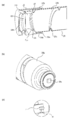
본 실시예에서, 펌프부(2)의 규제부는, 유지 부재(3)와 로크 부재(피결합 부재)(55)로 구성되어 있고, 유지 부재(3)는 로크 부재(55)와 결합함으로써 이동 불가하게 규제되어, 펌프부(2)의 상태를 유지하는 역할을 한다.In this embodiment, the restricting portion of the
이하, 규제부의 구체 구성을 설명한다. 도 9에 도시한 바와 같이, 유지 부재(3)는 역 ㄷ자 형상으로 되어 있고, 펌프부(2)의 상단부면으로부터 용기 본체(1a)의 양측면을 향해 뻗어 있다. 또한, 유지 부재(3)의 용기 본체(1a) 근방에 걸림 결합 돌기(3a)가 형성되어 있다. 또한, 상술한 바와 같이 걸림 지지 부재(9)의 걸림부(9a)와 걸림 결합하는 피결합부(3b)가 설치되어 있다.Hereinafter, a specific configuration of the regulating unit will be described. As shown in Fig. 9, the holding
한편, 로크 부재(55)는 도 9에 도시한 바와 같이, 용기 본체(1a)의 양측면에 설치된 회전축(1j)에 회전 지지부(55c)가 결합함으로써, 용기 본체(1a)에 대하여 회전 가능하게 설치되어 있다. 또한, 로크 부재(55)는, 유지 부재(3)의 걸림 결합 돌기(걸림부)(3a)가 끼워지는 결합 홈(피결합부)(55a)과, 현상제 보급 장치(8)의 걸림 결합 돌기(걸림부)(8j)(도 3 참조)가 끼워지는 결합 홈(피결합부)(55b)이 형성되어 있다.On the other hand, as shown in Fig. 9, the
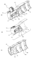
(현상제 보급 용기 장탈착 동작)(Developer removal / dispensing operation of developer supply container)
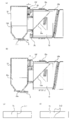
이어서, 도 13, 도 14를 사용하여 현상제 보급 용기(1)의 장착 동작에 대하여 설명한다. 여기서, 도 13의 (a), (b)는, 현상제 보급 용기(1)의 장착 도중의 각 부의 상태를 도시하는 도면이고, 도 14의 (a), (b)는, 현상제 보급 용기(1)의 장착 완료시의 각 부의 상태를 도시하는 도면이다.Next, the mounting operation of the
현상제 보급 용기(1)는 도 13의 (a)에 도시한 바와 같이, 현상제 보급 장치(8)에 장착하기 전에는 펌프부(2)가 줄어든 상태로 규제되어 있다. 이때, 도 13의 (b)에 도시한 바와 같이, 유지 부재(3)의 걸림 결합 돌기(3a)가 로크 부재(55)에 형성된 결합 홈(55a)에 끼워지고, 유지 부재(3)는 펌프부(2)의 탄성 복원력에 의해 화살표 p 방향으로의 가압력을 받고 있다. 이 가압력에 의해 회전 지지부(55c)와 회전축(1j)의 사이에 마찰력이 작용하여, 물류나 오퍼레이터의 부주의한 조작으로는 간단하게 로크 부재(55)가 회전하지 않도록 되어 있다.13 (a), the
이 상태의 현상제 보급 용기(1)를 현상제 보급 장치(8)에 장착해 가면, 도 13의 (a)에 도시한 바와 같이, 삽입 도중에 걸림 지지 부재(9)의 걸림부(9a)와 유지 부재(3)의 피결합부(3b)가 걸림 결합된다. 한편, 현상제 보급 용기(1)의 플랜지부(1g)와 현상제 보급 장치(8)의 위치 결정 가이드(8b)가 결합함으로써, 배출구(현상제 보급구)(1c)와 현상제 수용구(8a)의 위치 정렬이 행해진다. 또한 동시에, 도 13의 (b)에 도시한 바와 같이, 현상제 보급 장치(8)의 걸림 결합 돌기(8j)가 로크 부재(55)의 결합 홈(55b)에 인입된다. 그 후, 또한 현상제 보급 용기(1)를 삽입하면, 걸림 결합 돌기(8j)가 결합 홈(55b)의 벽(55b1)을 누름으로써, 로크 부재(55)를 도면 중 화살표 F 방향으로 회전시킨다. 그리고 장착 완료시는, 로크 부재(55)는 도 14의 (b)에 나타내는 위치로 회전해서, 걸림 결합 돌기(3a)는 결합 홈(55a)으로부터 화살표 p 방향으로 탈착 가능한 상태로 되고, 펌프부(2)의 규제는 해제된다.When the
또한, 도 13의 (b)에서, 걸림 결합 돌기(8j)와 벽(55b1)이 접촉하는 위치를 로크 부재(55)의 회전 중심으로부터 이격된 위치에 설정함으로써, 보다 가벼운 힘으로 로크 부재(55)를 회전시킬 수 있다. 본 구성은 오퍼레이터가 현상제 보급 장치(8)에 현상제 보급 용기(1)를 장착하는 동작을 이용해서 로크 부재(55)를 회전시키기 때문에, 상기와 같이 설정함으로써, 현상제 보급 용기(1)의 장착력을 조정할 수 있다. 이것은 본체의 스페이스나, 로크 부재(55)의 회전 각도 등에 따라서 적절히 설정할 수 있다.13B, by setting the position where the engaging
그리고, 도 14의 (b)에 도시한 바와 같이, 배출구(현상제 보급구)(1c)와 현상제 수용구(8a)가 연통된 시점에서, 현상제 보급 용기(1)의 장착 동작은 종료된다.14 (b), at the time when the discharge port (developer supply port) 1c and the
또한, 현상제 보급 용기(1)의 제거는, 상기 장착 동작의 역의 수순으로 행해진다. 구체적으로는, 보급 동작이 끝나면 걸림 지지 부재(9)는 후술하는 바와 같이 장착시의 위치로 제어되기 때문에, 걸림 결합 돌기(3a)는 도 14의 (b)에 도시한 바와 같은 결합 홈(55a) 내에 삽입된 상태로 되어 있다. 이 상태에서 현상제 보급 용기(1)의 제거를 행하면, 현상제 보급 장치(8)의 걸림 결합 돌기(8j)가 결합 홈(55a)의 벽(55b2)을 눌러, 로크 부재(55)가 화살표 F 방향의 역방향으로 회전한다. 그 결과, 도 13의 (b)에 도시한 바와 같이, 걸림 결합 돌기(3a)가 결합 홈(55a)에 끼워져, 걸림 결합 돌기(3a)의 이동은 다시 규제된 상태가 된다. 따라서, 결과적으로 펌프부(2)의 동작도 규제된다.In addition, removal of the
(현상제 보급 공정)(Developer dispensing process)
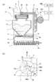
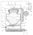
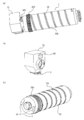
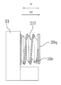
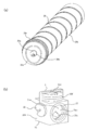
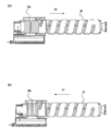
이어서, 도 15 내지 도 18을 사용하여, 펌프부(2)에 의한 현상제 보급 공정에 대하여 설명한다. 도 15는 펌프부(2)의 신축부(2a)가 줄어든 상태를 도시하는 개략 사시도이다. 도 16은 펌프부(2)의 신축부(2a)가 늘어난 상태를 도시하는 개략 사시도이다. 도 17은 펌프부(2)의 신축부(2a)가 줄어든 상태를 도시하는 개략 단면도이다. 도 18은 펌프부(2)의 신축부(2a)가 늘어난 상태를 도시하는 개략 단면도이다.Next, the developer supplying process by the
본 예에서는, 후술하는 바와 같이, 흡기 공정(배출구(1c)를 통한 흡기 동작)과 배기 공정(배출구(1c)를 통한 배기 동작)이 교대로 반복해서 행해지도록, 구동 변환 기구에 의해 회전력의 구동 변환이 행해지는 구성으로 되어 있다. 이하, 흡기 공정과 배기 공정에 대해서 순서대로 상세하게 설명한다.In this example, as will be described later, the driving force is applied to the driving mechanism by the driving mechanism so that the intake process (intake operation through the
우선, 펌프부를 사용한 현상제의 배출 원리에 대하여 설명한다.First, the discharge principle of the developer using the pump section will be described.
펌프부(2)의 신축부(2a)의 동작 원리는 상술한 바와 같다. 다시 설명하면, 도 10에 도시한 바와 같이, 신축부(2a)의 하단부는 용기 본체(1a)에 접합되어 있다. 또한, 이 용기 본체(1a)는 하단부의 플랜지부(1g)를 개재하여 현상제 보급 장치(8)의 위치 결정 가이드(8b)에 의해, 화살표 p 방향, 화살표 q 방향(필요에 따라 도 9 참조)으로의 이동이 저지된 상태가 된다. 그로 인해, 용기 본체(1a)와 접합되어 있는 신축부(2a)의 하단부는, 현상제 보급 장치(8)에 대하여 상하 방향의 위치가 고정된 상태로 된다.The operation principle of the stretchable and
한편, 신축부(2a)의 상단부는 유지 부재(3)를 개재하여 걸림 지지 부재(9)에 걸림 지지되어 있고, 이 걸림 지지 부재(9)가 상하 이동함으로써, 화살표 p 방향, 화살표 q 방향으로 왕복 이동한다.The upper end portion of the stretchable and
따라서, 펌프부(2)의 신축부(2a)는 하단부가 고정된 상태에 있으므로, 그것보다 상측의 부분이 신축 동작을 행하게 된다.Therefore, since the lower end portion of the
이어서, 펌프부(2)의 신축부(2a)의 신축 동작(배기 동작 및 흡기 동작)과 현상제 배출의 관계에 대하여 설명한다.Next, the relationship between the expansion and contraction operation (exhaust operation and intake operation) of the stretchable and
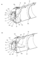
(배기 동작)(Exhaust operation)
우선, 배출구(1c)를 통한 배기 동작에 대하여 설명한다.First, the exhaust operation through the
도 15에 도시한 바와 같이, 걸림 지지 부재(9)가 아래쪽으로 이동함에 수반하여, 신축부(2a)의 상단부가 화살표 q 방향으로 변위함으로써(신축부가 줄어듦으로써), 배기 동작이 행해진다. 구체적으로는, 이 배기 동작에 수반하여 현상제 수용 스페이스(1b)의 용적이 감소되어 간다. 그때, 용기 본체(1a)의 내부는 배출구(1c)를 제외하면 밀폐되어 있으며, 현상제가 배출될 때까지는, 배출구(1c)가 현상제로 실질적으로 막힌 상태로 되어 있다. 그로 인해, 현상제 수용 스페이스(1b) 내의 용적이 감소되어 감으로써 현상제 수용 스페이스(1b)의 내압이 상승해 간다.The exhaust operation is performed by displacing the upper end portion of the stretchable and
이때, 현상제 수용 스페이스(1b)의 내압은 호퍼(8g) 내의 압력(대기압과 거의 동등)보다 커진다. 즉, 현상제 수용 스페이스(1b)의 내압이 대기압보다 높은 상태가 된다. 그로 인해, 도 17에 도시한 바와 같이, 현상제(T)는, 현상제 수용 스페이스(1b)와 호퍼(8g)의 압력차(대기압에 대한 차압)에 의해 공기압으로 압출된다. 즉, 현상제 수용 스페이스(1b)에서 호퍼(8g)로 현상제(T)가 배출된다. 도 17의 화살표는, 현상제 수용 스페이스(1b) 내의 현상제(T)에 작용하는 힘의 방향을 나타낸 것이다.At this time, the inner pressure of the
그 후, 현상제(T)와 함께 현상제 수용 스페이스(1b) 내의 에어도 배출되어 가기 때문에, 현상제 수용 스페이스(1b)의 내압은 저하되어 간다.Thereafter, the air in the
(흡기 동작)(Intake operation)
이어서, 배출구(1c)를 통한 흡기 동작에 대하여 설명한다.Next, the intake operation through the
도 16에 도시한 바와 같이, 걸림 지지 부재(9)가 상방으로 이동하는 것에 수반하여, 펌프부(2)의 신축부(2a)의 상단부가 화살표 p 방향으로 변위함으로써(신축부가 늘어남으로써), 흡기 동작이 행해진다. 구체적으로는, 이 흡기 동작에 수반하여 현상제 수용 스페이스(1b)의 용적이 증대되어 간다. 그때, 용기 본체(1a)의 내부는 배출구(1c)를 제외하면 밀폐된 상태로 되어 있어, 배출구(1c)가 현상제로 실질적으로 막힌 상태로 되어 있다. 그 때문에 현상제 수용 스페이스(1b) 내의 용적 증가에 수반하여, 현상제 수용 스페이스(1b)의 내압이 감소되어 간다.The upper end portion of the stretchable and
이때, 현상제 수용 스페이스(1b)의 내압은 호퍼(8g)의 내압(대기압과 거의 동등)보다 작아진다. 즉, 현상제 수용 스페이스(1b)의 내압이 대기압보다 낮은 상태가 된다. 그로 인해, 도 18에 도시한 바와 같이, 호퍼(8g) 내의 상부에 있는 에어가, 현상제 수용 스페이스(1b)와 호퍼(8g)의 압력차(대기압에 대한 차압)에 의해, 배출구(1c)를 통해 현상제 수용 스페이스(1b) 내로 이동한다. 도 18의 화살표는, 현상제 수용 스페이스(1b) 내의 현상제(T)에 작용하는 힘의 방향을 나타내고 있다. 또한, 도 18의 타원으로 나타낸 z는, 호퍼(8g)로부터 도입된 에어를 모식적으로 도시한 것이다.At this time, the inner pressure of the
그때, 배출구(1c)를 통해 현상제 보급 장치(8)측으로부터 에어가 도입되기 때문에, 배출구(1c) 근방에 위치하는 현상제를 풀 수 있다. 구체적으로는, 배출구(1c) 근방에 위치하는 현상제에 대하여 에어를 포함시킴으로써 부피 밀도를 저하시켜, 현상제를 유동화시킬 수 있다.At this time, since the air is introduced from the
이와 같이, 현상제를 유동화시켜 둠으로써, 다음 배기 동작시에, 배출구(1c)로부터 현상제를 폐색하지 않고 배출시키는 것이 가능하게 되는 것이다. 따라서, 배출구(1c)로부터 배출되는 현상제(T)의 양(단위 시간당)을 장기에 걸쳐서 거의 일정하게 하는 것이 가능하게 된다.By fluidizing the developer in this manner, it becomes possible to discharge the developer from the
(현상제 수용부의 내압의 추이)(Change in internal pressure of the developer accommodating portion)
이어서, 현상제 보급 용기(1)의 내압이 어떻게 변화하고 있는지에 대한 검증 실험을 행하였다. 이하, 이 검증 실험에 대하여 설명한다.Next, a verification experiment was conducted to see how the internal pressure of the
현상제 보급 용기(1) 내의 현상제 수용 스페이스(1b)가 현상제로 채워지도록 현상제를 충전한 뒤에, 펌프부(2)를 15cm3의 용적 변화량으로 신축시켰을 때의 현상제 보급 용기(1)의 내압의 추이를 측정하였다. 현상제 보급 용기(1)의 내압의 측정은, 현상제 보급 용기(1)에 압력계(가부시끼가이샤 키엔스사제, 제품명: AP-C40)를 접속해서 행하였다.The
현상제를 충전한 현상제 보급 용기(1)의 셔터(5)를 개방하여 배출구(1c)를 외부의 에어와 연통 가능하게 한 상태에서, 펌프부(2)를 신축 동작시키고 있을 때의 압력 변화의 추이를 도 19에 나타내었다.The pressure change when the
도 19에서, 횡축은 시간을 나타내고, 종축은 대기압(기준(0))에 대한 현상제 보급 용기(1) 내의 상대적인 압력을 나타내고 있다(+가 정압측, -가 부압측을 나타내고 있음).19, the abscissa indicates time and the ordinate indicates the relative pressure in the
현상제 보급 용기(1)의 용적이 증가하고, 현상제 보급 용기(1)의 내압이 외부의 대기압에 대하여 부압이 되면, 그 기압차(대기압에 대한 차압)에 의해 배출구(1c)로부터 에어가 도입된다. 또한, 현상제 보급 용기(1)의 용적이 감소하고, 현상제 보급 용기(1)의 내압이 대기압에 대해 정압이 되면, 그 기압차(대기압에 대한 차압)에 의해 현상제 보급 용기(1) 내부의 현상제에 압력이 가해진다. 이때, 현상제 및 에어가 배출된 분만큼 내부의 압력이 완화된다.When the volume of the
이 검증 실험에 의해, 현상제 보급 용기(1)의 용적이 증가함으로써 현상제 보급 용기(1)의 내압이 외부의 대기압에 대하여 부압이 되어, 그 기압차에 의해 에어가 도입되는 것을 확인할 수 있었다. 또한, 현상제 보급 용기(1)의 용적이 감소됨으로써 현상제 보급 용기(1)의 내압이 대기압에 대해 정압이 되어, 그 기압차에 의해 용기 내부의 현상제에 압력이 가해짐으로써 현상제가 배출되는 것을 확인할 수 있었다. 이 검증 실험에서는, 부압측의 압력의 절대값은 1.3kPa, 정압측의 압력의 절대값은 3.0kPa이었다.As a result of this verification experiment, it was confirmed that the internal pressure of the
이와 같이, 본 예의 구성의 현상제 보급 용기(1)이면, 펌프부(2)에 의한 흡기 동작과 배기 동작에 수반하여 현상제 보급 용기(1)의 내압이 부압 상태와 정압 상태로 교대로 전환되어, 현상제의 배출을 적절하게 행하는 것이 가능해짐이 확인되었다.As described above, in the
이상 설명한 대로, 본 예에서는, 현상제 보급 용기(1)에 흡기 동작과 배기 동작을 행하는 간이한 펌프를 설치함으로써, 에어에 의해 현상제를 푸는 효과를 얻으면서, 에어에 의한 현상제의 배출을 안정적으로 행할 수 있다.As described above, in this embodiment, the
즉, 본 예의 구성이면, 배출구(1c)의 크기가 매우 작은 경우에도, 현상제를 부피 밀도가 작은 유동화한 상태에서 배출구(1c)를 통과시킬 수 있기 때문에, 현상제에 큰 스트레스를 주지 않고 높은 배출 성능을 확보할 수 있다.In other words, with the structure of this example, even if the size of the
또한, 본 예에서는, 용적 가변형의 펌프부(2)의 내부를 현상제 수용 스페이스(1b)로서 이용하는 구성으로 하고 있기 때문에, 펌프부(2)의 용적을 증대시켜서 내압을 감압시킬 때, 새로운 현상제 수용 공간을 형성할 수 있다. 따라서, 펌프부(2)의 내부가 현상제로 채워져 있는 경우에도, 간이한 구성으로, 현상제에 에어를 포함시켜서 부피 밀도를 저하시킬 수 있다(현상제를 유동화시킬 수 있음). 따라서, 현상제 보급 용기(1)에 현상제를 종래 이상으로 고밀도로 충전시키는 것이 가능하게 된다.In this embodiment, since the inside of the capacity variable
또한, 이상과 같이, 펌프부(2)의 내부 공간을 현상제 수용 스페이스(1b)로서 사용하지 않고, 필터(에어는 통과할 수 있지만 토너는 통과할 수 없는 필터)에 의해 펌프부(2)와 현상제 수용 스페이스(1b)의 사이를 구획하는 구성으로 해도 상관없다. 단, 펌프의 용적 증대시에 새로운 현상제 수용 공간을 형성할 수 있는 점에서, 상술한 실시예의 구성이 보다 더 바람직하다.As described above, the internal space of the
(흡기 공정에서의 현상제의 풀어짐 효과에 대해서)(About the effect of releasing the developer in the intake process)
이어서, 흡기 공정에서의 배출구(1c)를 통한 흡기 동작에 의한 현상제의 풀어짐 효과에 대하여 검증을 행하였다. 또한, 배출구(1c)를 통한 흡기 동작에 수반하는 현상제의 풀어짐 효과가 크면, 작은 배기압(적은 펌프 용적 변화량)으로, 다음 배기 공정에서 현상제 보급 용기(1) 내의 현상제의 배출을 바로 개시시킬 수 있다. 따라서, 본 검증은, 본 예의 구성이면, 현상제의 풀어짐 효과가 현저하게 높아지는 것을 나타내기 위한 것이다. 이하, 상세하게 설명한다.Then, the effect of releasing the developer by the intake operation through the
도 20의 (a), 도 21의 (a)에 검증 실험에 사용한 현상제 보급 시스템의 구성을 간이하게 나타낸 블록도를 나타낸다. 도 20의 (b), 도 21의 (b)는 현상제 보급 용기 내에서 발생하는 현상을 도시하는 개략도이다. 또한, 도 20은 본 예와 마찬가지의 방식의 경우이며, 현상제 보급 용기(C)에 현상제 수용부(C1)와 함께 펌프부(P)가 설치되어 있다. 그리고, 펌프부(P)의 신축 동작에 의해 현상제 보급 용기(C)의 배출구(본 예와 마찬가지의 배출구(1c)(도시하지 않음))를 통한 흡기 동작과 배기 동작을 교대로 행하여, 호퍼(H)에 현상제를 배출하는 것이다. 한편, 도 21은 비교예의 방식의 경우이며, 펌프부(P)를 현상제 보급 장치측에 설치하여, 펌프부(P)의 신축 동작에 의해 현상제 수용부(C1)에 대한 송기 동작과 현상제 수용부(C1)로부터의 흡인 동작을 교대로 행하여, 호퍼(H)에 현상제를 배출시키는 것이다. 또한, 도 20, 도 21에서, 현상제 수용부(C1), 호퍼(H)는 동일한 내용적이고, 펌프부(P)도 동일한 내용적(용적 변화량)으로 되어 있다.20 (a) and 21 (a) are simplified block diagrams showing the configuration of the developer replenishing system used for the verification test. 20 (b) and 21 (b) are schematic views showing the phenomenon occurring in the developer replenishing container. 20 shows a case of the same method as that of the present example, in which the developer supplying portion C1 and the pump portion P are provided in the developer supplying container C. By the expansion and contraction operation of the pump section P, the intake operation and the exhaust operation are alternately performed through the discharge port (the
우선, 현상제 보급 용기(C)에 200g의 현상제를 충전한다.First, 200 g of the developer is charged into the developer replenishing container (C).
이어서, 현상제 보급 용기(C)의 물류 후의 상태를 상정해서 15분간에 걸쳐 가진을 행한 후, 호퍼(H)에 접속한다.Then, the developer replenishing container C is subjected to excitation for 15 minutes under the assumption of the state after the distribution, and then the hopper H is connected.
그리고, 펌프부(P)를 동작시켜서, 배기 공정에서 즉시 현상제를 배출 개시시키기 위해 필요한 흡기 공정의 조건으로서, 흡기 동작시에 달하는 내압의 피크값을 측정하였다. 또한, 도 20의 경우에는 현상제 수용부(C1)의 용적이 480cm3가 되는 상태, 도 21의 경우에는 호퍼(H)의 용적이 480cm3가 되는 상태를 각각 펌프부(P)의 동작을 스타트시키는 위치로 하고 있다.Then, the peak value of the internal pressure at the time of the intake operation was measured as the condition of the intake process required for operating the pump section P to immediately start the developer discharge in the exhaust process. In addition, the state, the action of, the hopper (H) pump section (P) the state respectively that is 480cm 3 volume of the case of Figure 21 In the case of 20, the volume of the developer housing section (C1) that is 480cm 3 We assume position to start.
또한, 도 21의 구성에서의 실험은, 도 20의 구성과 공기 용적의 조건을 정렬시키기 위해서, 미리 호퍼(H)에 200g의 현상제를 충전한 뒤에 행하였다. 또한, 현상제 수용부(C1) 및 호퍼(H)의 내압은, 각각에 압력계(가부시끼가이샤 기엔스사제, 제품명: AP-C40)를 접속함으로써 측정을 행하였다.The experiment in the configuration of Fig. 21 was carried out after filling the hopper (H) with 200 g of the developer in advance in order to align the configuration of Fig. 20 with the conditions of the air volume. The internal pressure of the developer accommodating portion C1 and the hopper H were measured by connecting a pressure gauge (product name: AP-C40 manufactured by Kabushiki Kaisha Gensen Co., Ltd.) to each.
검증의 결과, 도 20에 나타내는 본 예와 마찬가지의 방식에서는, 흡기 동작시의 내압의 피크값(부압)의 절대값이 적어도 1.0kPa이면, 다음 배기 공정에서 현상제를 즉시 배출 개시시킬 수 있었다. 한편, 도 21에 나타내는 비교예의 방식에서는, 송기 동작시의 내압의 피크값(정압)이 적어도 1.7kPa가 아니면, 다음 배기 공정에서 현상제를 즉시 배출 개시시킬 수 없었다.As a result of the verification, if the absolute value of the peak value (negative pressure) of the internal pressure during the intake operation is at least 1.0 kPa, the developer can be immediately started to be discharged in the next exhaust process. On the other hand, in the method of the comparative example shown in Fig. 21, if the peak value (static pressure) of the internal pressure at the time of the air sending operation is not at least 1.7 kPa, the developer can not be immediately discharged at the next exhausting step.
즉, 도 20에 나타내는 본 예와 마찬가지의 방식이면, 펌프부(P)의 용적 증가에 수반해서 흡기가 행해지므로, 현상제 보급 용기(C)의 내압을 대기압(용기 밖의 압력)보다 낮은 부압측으로 할 수 있어, 현상제의 풀어짐 효과가 현저하게 높은 것이 확인되었다. 이것은, 도 20의 (b)에 도시한 바와 같이, 펌프부(P)의 신장에 수반하여 현상제 보급 용기(C)의 용적이 증가함으로써, 현상제층(T)의 상부의 공기층(R)이 대기압에 대해 감압 상태로 되기 때문이다. 그로 인해, 이 감압 작용에 의해 현상제층(T)의 체적이 팽창하는 방향으로 힘이 작용하기 때문에(파선 화살표), 현상제층을 효율적으로 푸는 것이 가능하게 되는 것이다. 또한, 도 20의 방식에서는, 이 감압 작용에 의해, 현상제 보급 용기(C) 내에 외부로부터 에어가 도입되게 되고(백색 화살표), 이 에어가 공기층(R)에 도달할 때에도 현상제층(T)이 풀어지게 되며, 매우 우수한 시스템이라고 할 수 있다. 현상제 보급 용기(C) 내의 현상제가 풀어져 있다는 증거로, 본 실험에서는 흡기 동작시에 현상제 보급 용기(C) 내의 현상제 전체의 겉보기 체적이 증가되어 있는 현상을 확인했다(현상제의 상면이 위로 움직이는 현상).20, the internal pressure of the developer replenishing container C is lowered to the negative pressure side which is lower than the atmospheric pressure (pressure outside the container) because the suction is carried out with the increase in the volume of the pump section P. In this case, And it was confirmed that the effect of releasing the developer was remarkably high. This is because as the volume of the developer replenishing container C increases with the extension of the pump portion P as shown in Figure 20 (b), the air layer R on the upper side of the developer layer T This is because the pressure is reduced with respect to atmospheric pressure. As a result, since the force acts in the direction in which the volume of the developer layer T expands due to this pressure reducing action (broken line arrow), it is possible to efficiently solve the developer layer. 20, air is introduced from the outside into the developer replenishing container C (white arrow) by the pressure reducing action, and even when the air reaches the air layer R, Which is a very good system. As a result of the fact that the developer in the developer replenishing container C is released, in the present experiment, the phenomenon that the apparent volume of the entire developer in the developer replenishing container C was increased during the intake operation was ascertained Moving upward).
한편, 도 21에 나타내는 비교예의 방식에서는, 현상제 수용부(C1)에 대한 송기 동작에 수반하여 현상제 보급 용기(C)의 내압이 높아져 대기압보다 높은 정압측이 되어버려 현상제가 응집되기 때문에, 현상제의 풀어짐 효과가 보이지 않았다. 이것은, 도 21의 (b)에 도시한 바와 같이, 현상제 보급 용기(C)의 외부로부터 에어가 강제적으로 보내지기 때문에, 현상제층(T)의 상부의 공기층(R)이 대기압에 대해 가압 상태로 되기 때문이다. 그로 인해, 이 가압 작용에 의해, 현상제층(T)의 체적이 수축하는 방향으로 힘이 작용하기 때문에(파선 화살표), 현상제층(T)이 압밀화되어버리는 것이다. 실제로, 비교예에서는 흡기 동작시에 현상제 보급 용기(C) 내의 현상제 전체의 외관 체적이 증가하는 현상을 확인할 수 없었다. 따라서, 도 21의 방식에서는, 현상제층(T)의 압밀화에 의해, 그 후의 현상제 배출 공정을 적절하게 행할 수 없을 우려가 높다.On the other hand, in the method of the comparative example shown in Fig. 21, the inner pressure of the developer replenishing container C becomes higher with the air sending operation to the developer accommodating portion C1 and becomes the positive pressure side higher than the atmospheric pressure, The effect of releasing the developer was not observed. This is because air is forcibly sent from the outside of the developer replenishing container C as shown in Fig. 21 (b), so that the air layer R above the developer layer T is pressed against the atmospheric pressure . As a result, the pressing force acts on the developer layer T in the direction in which the volume of the developer layer T contracts (indicated by the broken line), so that the developer layer T is compacted. In fact, in the comparative example, it was impossible to confirm that the appearance volume of the entire developer in the developer replenishing container C increased during the intake operation. Therefore, in the method of Fig. 21, there is a high possibility that the subsequent developer discharging step can not be appropriately performed by compaction of the developer layer T.
또한, 상기한 공기층(R)이 가압 상태가 됨으로 인한 현상제층(T)의 압밀화를 방지하기 위해서, 공기층(R)에 상당하는 부위에 공기빼기용의 필터 등을 설치하여, 압력 상승을 저감하는 것도 생각할 수 있지만, 필터 등의 투기 저항분은 공기층(R)의 압력이 상승되어버린다. 또한, 압력 상승을 가령 없앴다고 해도, 상술한 공기층(R)을 감압 상태로 함으로 인한 풀어짐 효과는 얻어지지 않는다.In order to prevent compaction of the developer layer T due to the air layer R being brought into the pressurized state, a filter for removing air may be provided at a portion corresponding to the air layer R to reduce the pressure rise However, the air resistance R of the filter or the like increases the pressure of the air layer R. In addition, even if the pressure rise is eliminated, the unwinding effect due to the above-described pressure reduction of the air layer R is not obtained.
이상으로부터, 도 20에 나타내는 본 예의 방식을 채용함으로써, 펌프부의 용적 증가에 수반하는 "배출구를 통한 흡기 동작"이 해내는 역할이 큰 것으로 확인되었다.From the above, it was confirmed that the adoption of the system of this example shown in Fig. 20 has a great role to play in " intake operation through the exhaust port " accompanied by increase in the volume of the pump section.
이상과 같이, 펌프부(2)가 배기 동작과 흡기 동작을 교대로 반복해서 행함으로써, 현상제 보급 용기(1)의 배출구(1c)로부터 현상제의 배출을 효율적으로 행하는 것이 가능하게 된다. 즉, 본 예에서는, 배기 동작과 흡기 동작을 동시에 병행하여 행하는 것이 아니라, 교대로 반복해서 행하는 구성으로 하고 있으므로, 현상제의 배출에 필요한 에너지를 가급적으로 적게 할 수 있다.As described above, by alternately repeating the exhaust operation and the intake operation by the
한편, 종래와 같이 현상제 보급 장치측에 송기용 펌프와 흡인용 펌프를 별도로 설치한 경우에는, 2개의 펌프 동작을 제어할 필요가 있으며, 특히 급속하게 송기와 흡기를 교대로 전환하는 것이 용이하지 않다.On the other hand, when the air supply pump and the suction pump are provided separately on the side of the developer dispenser as in the prior art, it is necessary to control the two pump operations, and it is not easy to switch air supply and intake air alternately rapidly .
따라서, 본 예에서는, 1개의 펌프를 사용하여 현상제의 배출을 효율적으로 행할 수 있으므로, 현상제 배출 기구의 구성을 간이화할 수 있다.Therefore, in this embodiment, since the developer can be efficiently discharged using one pump, the configuration of the developer discharging mechanism can be simplified.
또한, 상술한 바와 같이 펌프의 배기 동작과 흡기 동작을 교대로 반복함으로써 현상제의 배출을 효율적으로 행할 수 있지만, 배기 동작, 흡기 동작을 도중에 한번 정지했다가 다시 동작시켜도 상관없다.As described above, the developer can be efficiently discharged by alternately repeating the exhaust operation and the intake operation of the pump. However, the exhaust operation and the intake operation may be stopped and restarted once in the middle.
예를 들어, 펌프의 배기 동작을 한꺼번에 행하는 것이 아니라, 펌프의 압축 동작을 도중에 한번 정지하고, 그 후 다시 압축해서 배기해도 된다. 흡기 동작도 마찬가지이다. 또한, 배출량 및 배출 속도를 만족한다는 전제로, 각 동작을 다단계로 해도 상관없다. 단, 어디까지나 펌프의 동작은 다단계로 분할한 배기 동작 후, 흡기 동작을 행하여, 기본적으로 배기 동작과 흡기 동작을 반복하는 것에는 변함이 없다.For example, instead of performing the exhaust operation of the pump at once, the compression operation of the pump may be stopped once in the middle, and then compressed and exhausted again. The same is true for the intake operation. In addition, each operation may be set to a multi-stage based on the assumption that the discharge amount and the discharge speed are satisfied. However, the operation of the pump is essentially the same as repeating the exhaust operation and the intake operation by performing the intake operation after the exhaust operation divided into multiple stages.
또한, 본 예에서는, 현상제 수용 스페이스(1b)의 내압을 감압 상태로 함으로써 배출구(1c)로부터 에어를 도입하여 현상제를 풀고 있다. 한편, 상술한 비교예에서는, 현상제 보급 용기(1) 외부로부터 현상제 수용 스페이스(1b)에 에어를 보내옴으로써 현상제를 풀고 있는데, 그때, 현상제 수용 스페이스(1b)의 내압은 가압 상태로 되어 있어, 현상제가 응집되어버린다. 즉, 현상제를 푸는 효과로는 현상제가 응집되기 어려운 감압 상태에서 풀 수 있는 본 예가 더 바람직하다.In this example, air is introduced from the
(보급 개시시의 현상제의 풀어짐 효과에 대해서)(About the effect of releasing the developer at the time of start of supply)
현상제 보급 용기(1) 내의 현상제는, 상술한 바와 같이, 장기 방치 등의 영향에 의해 포함하고 있었던 공기가 빠져서 압밀되는 경우가 있다. 특히, 신품의 현상제 보급 용기(1)는, 유저가 있는 곳까지의 물류 이송 중에 진동이 가해지거나, 고온 고습하에 장기간 방치 보관됨으로써, 실제의 사용시에는 현상제가 압밀되어 있을 가능성이 보다 높다. 이러한 상태의 현상제 보급 용기(1)에 있어서, 펌프부(2)를 도 18에 나타내는 상태에서 용적을 작게 하는 방향으로 동작시켜 보급 동작을 개시시키면, 용적의 감소에 의해 현상제 보급 용기(1) 내는 가압되기 때문에, 내부의 현상제는 더 압밀되어버린다. 그 결과, 배출구(현상제 보급구)(1c) 주변의 현상제가 폐색되어, 현상제의 배출 불량이 발생할 우려가 있다. 또한, 배출구(1c)가 막히면, 펌프부(2)의 동작에 큰 구동 부하가 발생해버리게 된다.As described above, the developer contained in the
한편, 펌프부(2)를 도 17에 나타내는 상태에서 용적을 크게 하는 방향으로 동작시켜 보급 동작을 개시시키면, 상술한 바와 같이, 배출구(1c)로부터 현상제 보급 용기(1) 내에 공기가 도입된다. 그 결과, 배출구(1c) 주변의 압밀된 현상제는 유동화되어 풀어진다. 그리고 그 직후에 펌프부(2)를 용적이 작아지는 방향으로 동작시키면, 풀어진 현상제는 배출구(1c)로부터 원활하게 배출된다.17, air is introduced into the
따라서, 현상제 보급 용기(1)의 현상제 보급 동작에서의 최초의 동작은, 펌프부(2)의 용적을 크게 하는 방향으로 동작시켜서 공기를 도입하는 단계인 것이 바람직하다.Therefore, it is preferable that the first operation in the developer replenishing operation of the
본 실시예에서, 현상제 보급 용기(1)는, 상술한 바와 같은 규제부(유지 부재(3), 로크 부재(55))에 의해 현상제 보급 동작 개시 전의 펌프부(2)의 상태를 규제하는 것이 가능하다. 즉, 펌프부(2)의 최초의 동작 주기에서 배출구(1c)로부터 현상제 수용 스페이스(1b) 내에 에어가 도입되도록 상기 펌프부(2)의 동작 개시시의 위치를 도 17에 나타내는 위치로 규제하는 것이 가능하다. 따라서, 현상제 보급 용기(1)는 규제부에 의해 펌프부(2)를 축소시킨 상태(도 17에 나타내는 상태)에서 규제하여, 보급 동작을 확실하게 펌프부(2)의 용적을 크게 하는 방향으로부터 개시할 수 있도록 설정하는 것이 가능하다.In this embodiment, the
또한, 상술한 바와 같이, 공기 도입에 의한 현상제의 풀어짐 효과가 가장 필요해지는 것은, 신품의 현상제 보급 용기(1)를 사용할 때이다. 그러나, 예를 들어 현상제 보급 용기(1)가 현상제 보급 장치(8)에 장착된 상태에서, 유저가 장기간 카피 동작을 행하지 않는 경우, 장기 방치에 의해 현상제 보급 용기(1) 내에 남아 있던 현상제는 마찬가지로 압밀될 가능성이 있다. 이러한 상황에서도 본 발명의 효과를 얻기 위해서는, 펌프 동작을 재개할 때의 펌프부(2)의 위치도 장착시와 동일 위치, 즉 용적을 크게 하는 방향으로부터 개시시키는 위치로 규제해 두는 것이 바람직하다. 그러기 위해서는, 예를 들어 현상제 보급 장치(8)의 걸림 지지 부재(9)의 위치를 센싱하는 센서를 장치 본체(100)에 설치하고, 그것에 의해 걸림 지지 부재(9)를 현상제 보급 용기(1) 장착시의 위치와 확실하게 동일 위치에서 정지시키는 구성 등을 생각할 수 있는데, 물론 그 밖의 구성이어도 상관없다. 또한, 이 제어 수단이 있으면, 예를 들어 어떠한 사정에 의해 현상제 보급 용기(1) 내에 현상제가 남은 상태에서 현상제 보급 장치(8)로부터 탈착했다가 재장착하여 보급을 재개한 경우에도, 보급 동작을 확실하게 펌프부(2)의 용적을 크게 하는 방향으로부터 개시할 수 있기 때문에, 마찬가지의 효과를 얻을 수 있다. 또한, 이 제어 수단이 있으면, 예를 들어 현상제 보급 용기(1)에 규제부를 설치하지 않아도, 현상제 보급 용기(1)를 현상제 보급 장치(8)에 장착할 때에 피결합부(3b)와 걸림 지지 부재(9)와 걸림 결합이 가능하다면, 보급 동작을 확실하게 펌프부(2)의 용적을 크게 하는 방향으로부터 개시할 수 있다. 그러나, 현상제 보급 용기(1)에 규제부가 없으면 현상제 보급 용기(8)에 장착하기 전의 피결합부(3b)의 위치를 규제할 수 없기 때문에, 유저가 걸림 지지 부재(9)에 대하여 피결합부(3b)가 결합하도록 위치 정렬을 하면서 장착 동작을 행해야만 한다. 따라서, 조작성 향상의 관점에서, 본 발명과 같이 현상제 보급 용기(1)에 규제부를 설치하는 구성이 보다 바람직하다.In addition, as described above, the effect of releasing the developer by the air introduction is most needed when a new
또한, 본 실시예에서, 규제부에 의한 펌프부(2)의 규제 해제 및 재규제 동작은, 현상제 보급 용기(1)의 현상제 보급 장치(8)에 대한 장탈착 동작에 수반하는 것으로 하였다. 단, 이것에 한정하는 것은 아니고, 예를 들어 교환용 커버(40)(도 2 참조)의 개폐 동작에 연동해서 행해져도 상관없다. 또한, 장치 본체(100) 내에 자동으로 동작을 행하는 기구를 설치하고, 그것을 장치 본체(100)의 조작 패널(100b)(도 2 참조)의 조작에 의해 가동시켜도 상관없다.In this embodiment, the regulation releasing and re-regulating operation of the
이상과 같이, 본 실시예의 구성에 의하면, 펌프부(2)의 동작을 용적 증대 방향으로부터 항상 개시시킬 수 있다. 그로 인해, 배출구(현상제 보급구)(1c) 주변에서 현상제가 압밀되어 굳어지는 상태가 발생해도, 확실하게 공기의 도입에 의해 현상제를 유동화시킴으로써, 초기부터 안정 배출시킬 수 있다.As described above, according to the configuration of the present embodiment, the operation of the
또한, 용적 증대 방향으로부터 개시시키면 공기 도입으로 현상제가 확실하게 풀어지기 때문에, 그 후의 펌프 동작의 구동력은 작아져서 본체에 가해지는 구동 부하는 적어진다.In addition, when starting from the volume increasing direction, since the developer is surely released by the air introduction, the driving force for the subsequent pump operation is reduced, and the driving load applied to the main body is reduced.
또한, 주름 상자 형상의 펌프부(2)에 있어서, 주름 상자의 홈에 현상제가 낀 상태에서 펌프 동작을 용적 감소 방향으로부터 개시시키면, 홈 내의 현상제에 더욱 압축력이 가해져, 화질에 영향을 미치는 응집체나 조대 입자가 발생할 우려가 있다. 그에 반해, 펌프 동작을 용적 증대 방향으로부터 개시시키는 경우에는, 펌프부(2)는 주름 상자가 줄어든 상태에서 세팅하기 때문에 동작 개시 전에 홈에 끼는 현상제도 적다. 또한, 펌프부(2)는 신장 방향으로 동작해서 현상제를 더 압축하지 않기 때문에, 응집체나 조대 입자의 발생을 방지할 수 있다.Further, in the
이어서, 본 실시예에서의 현상제 보급 용기(1)의 현상제 배출 성능에 대하여, 이하에 나타내는 실험예를 사용해서 상세하게 설명한다.Next, the developer discharging performance of the
실험 수순을 설명한다. 우선, 도 9에 나타내는 현상제 보급 용기(1)에 현상제(240g)를 충전하였다. 그 후, 배출구(현상제 보급구)(1c)를 아래로 한 상태에서 물류시에 상당하는 진동을 가하여 현상제를 압밀시켰다. 여기서, 진동은 높이 30mm에서의 낙하 동작을 1000회 가하여 행하였다. 그리고 현상제 보급 용기(1)를 장치 본체(100) 내에 장착해서 배출구(1c)를 개봉하고, 용적 변화량 15cm3, 용적 변화 속도 90cm3/s의 조건으로 펌프부(2)를 동작시켜서 보급 동작을 행하였다.The experimental procedure will be described. First, the
또한, 현상제 보급 용기(1) 내에 공기가 도입되어 있는지를 확인하기 위해서, 현상제 보급 용기(1)의 내압의 추이를 측정하였다. 내압의 측정은, 현상제 보급 용기(1)에 압력계(가부시끼가이샤 기엔스사제, 제품명: AP-C40)를 접속해서 행하였다.Further, in order to confirm whether air was introduced into the
또한, 본 실험에서 사용한 장치 본체(100)는, 90초 동안에 서브 호퍼 내에 현상제가 소정량 채워지지 않을 경우에는 현상제 보급 용기(1)의 교환 메시지가 나오도록 설정하였다.In addition, the apparatus
<실험예 1><Experimental Example 1>
실험예 1로서, 펌프부(2)를 가장 줄어든 상태에서부터 용적 증대 방향으로 동작시켜서, 현상제 보급 용기(1)의 보급 동작을 개시시켰다. 그 결과, 펌프부(2)의 동작 직후부터 현상제 보급 용기(1)로부터 현상제가 배출되어, 배출 완료까지 문제없이 사용할 수 있었다.In Experimental Example 1, the
또한, 배출 개시시의 현상제 보급 용기(1)의 내압의 추이를, 도 22의 (a)에 나타내었다. 여기서, 도 22의 (a)에서, 횡축은 시간을 나타내고, 종축은 대기압(기준(0))에 대한 현상제 보급 용기(1) 내의 상대적인 압력을 나타내고 있다(+가 정압측, -가 부압측을 나타내고 있음). 현상제 보급 용기(1)의 용적 증가에 의해, 현상제 보급 용기(1)의 내압은 외부의 대기압에 대해 부압이 되고, 그 후 현상제 보급 용기(1)의 용적 감소에 의해, 현상제 보급 용기(1)의 내압은 대기압에 대해 부압에서 정압으로 이행하고 있었다. 또한, 이때의 부압측의 압력 피크의 절대값(최대값)(P2)은 1.3kPa이었다.The change in internal pressure of the
여기서, 실험예 1의 구성에 있어서, 현상제 보급 용기(1) 내에 공기가 도입되어 있는 것을 실증하는 실험으로서, 배출구(1c)를 밀봉하여 현상제 보급 용기(1) 내에 공기가 도입되지 않는 상황으로 한 상태(밀폐 상태)에서, 실험예 1과 마찬가지의 실험을 행하였다. 그 결과, 현상제 보급 용기(1)의 용적 증가에 의해, 현상제 보급 용기(1)의 내압은 외부의 대기압에 대하여 부압으로 되지만, 그 후 현상제 보급 용기(1)의 용적 감소 동작 종료시에 있어서는, 현상제 보급 용기(1)의 내압은 대기압과 동등하게 되고, 정압 상태는 되지 않았다. 또한, 이때의 부압측의 압력 피크의 절대값(최대값)(P1)은 2.5kPa이었다. P1보다 P2가 하회한 것은(|P1|>|P2|), 배출구(현상제 보급구)(1c)로부터 공기가 도입됨으로써, 현상제 보급 용기(1) 내의 공기의 팽창이 완화되었기 때문이다.Here, as an experiment to demonstrate the introduction of air into the
이들 결과로부터, 실험예 1의 구성에서는 보급 개시 직후부터 현상제 보급 용기(1) 내에 공기가 도입되고, 그것에 의해 압밀된 현상제의 풀어짐 효과가 발생한 것이 실증되었다.From these results, it was proven that the air in the
<실험예 2><Experimental Example 2>
실험예 2로서, 펌프부(2)의 최대 신장시의 상태에 대하여 절반으로 축소된 상태에서 용적 증대 방향으로 동작시켜, 현상제 보급 용기(1)의 보급 동작을 개시시켰다. 그 밖의 실험 조건은, 실험예 1과 동일하게 하였다. 그 결과, 펌프부(2)의 동작 개시 직후는 현상제 보급 용기(1)로부터 현상제가 충분 양 배출되지 않았지만, 펌프 동작을 수회 행한 후에는 안정적으로 배출되어, 최종적으로는 배출 완료까지 문제없이 사용할 수 있었다.In Experimental Example 2, the operation of the
또한, 배출 개시시의 현상제 보급 용기(1)의 내압의 추이를, 도 22의 (a)에 나타내었다. 내압의 추이 경향은 실험예 1과 거의 동일하지만, 부압측의 압력 피크의 절대값은 2.0kPa로, 실험예 1의 구성의 압력값을 상회하고 있었다. 이것은, 실험예 2의 구성은 실험예 1보다 펌프부(2)의 용적 변화량이 적기 때문에, 배출구(1c)로부터의 공기의 도입량이 적었으므로, 실험예 1의 구성만큼 현상제 보급 용기(1) 내의 공기의 팽창이 완화되지 않았기 때문이다.The change in internal pressure of the
이 결과로부터, 실험예 2의 구성이어도, 현상제 보급 용기(1) 내에 공기는 도입되어, 현상제의 풀어짐 효과가 얻어지는 것을 확인할 수 있었다. 그러나, 보다 높은 배출 성능을 얻기 위해서는, 실험예 1과 같이 펌프부(2)의 용적 증가 방향으로의 변화량을 최대로 설정하는 것이 보다 바람직한 것으로 실증되었다.From this result, it was confirmed that even in the configuration of Experimental Example 2, air was introduced into the
<실험 비교예 1><Experimental Comparative Example 1>
실험 비교예 1로서, 펌프부(2)를 가장 신장한 상태에서 용적 감소 방향으로 동작시켜, 현상제 보급 용기(1)의 보급 동작을 개시시켰다. 그 밖의 실험 조건은, 실험예 1과 동일하게 하였다. 그 결과, 현상제 보급 용기(1)로부터는 현상제가 배출되지 않고, 90초 후에 현상제 보급 용기의 교환 메시지가 표시되었다. 그 후, 180초 정도까지 보급 동작을 계속했지만 현상제는 배출되지 않았다.As Experimental Comparative Example 1, the
또한, 배출 개시시의 현상제 보급 용기(1)의 내압의 추이를 도 22의 (b)에 나타내었다. 현상제 보급 용기(1)의 용적 감소에 의해, 현상제 보급 용기(1)의 내압은 외부의 대기압에 대하여 정압이 되기는 하지만, 그 후 현상제 보급 용기(1)의 용적 증가 동작 종료시에 있어서는, 현상제 보급 용기(1)의 내압은 대기압과 동등하게 되고, 부압 상태는 되지 않았다. 이것은, 배출구(현상제 보급구)(1c)를 밀봉해서 마찬가지의 실험을 행한 것과 동일한 거동이다. 즉 용적 감소에 의해 현상제 보급 용기(1) 내가 가압됨으로써, 배출구(1c) 주변의 현상제가 압밀됨으로써, 배출구(1c)가 실질적으로 폐색된 것을 나타내고 있다.22 (b) shows the change in internal pressure of the
이 결과로부터, 펌프부(2)의 동작을 용적 증대 방향으로 스타트시킴으로 인한 배출 성능 향상의 효과를 확인할 수 있었다.From this result, it is possible to confirm the effect of improving the discharge performance by starting the operation of the
[실시예 2][Example 2]
이어서, 실시예 2의 구성에 대해서, 도 23, 도 24를 사용하여 설명한다. 여기서, 도 23은 현상제 보급 용기(1)의 개략 사시도를, 도 24는 현상제 보급 용기(1)의 개략 단면도를 도시하고 있다. 또한, 본 예에서는, 펌프부의 구성이 실시예 1과 다를 뿐이며, 그 밖의 구성은 실시예 1과 거의 마찬가지이다. 따라서, 본 예에서는, 상술한 실시예 1과 마찬가지의 구성에 대해서는 동일한 부호를 붙임으로써 상세한 설명을 생략한다.Next, the configuration of the second embodiment will be described with reference to FIGS. 23 and 24. FIG. Here, FIG. 23 is a schematic perspective view of the
본 예에서는, 도 23, 도 24에 도시한 바와 같이, 실시예 1과 같은 주름 상자 형상의 용적 가변형의 펌프부 대신에 플런저형의 펌프부를 사용하고 있다. 본 예의 플런저형의 펌프부도, 상술한 실시예 1과 마찬가지로, 용적을 증감시킴으로써 현상제 수용 스페이스(1b) 내의 내압을 변화시키는 용적 가변부이다. 구체적으로는, 본 예의 플런저형 펌프부는, 내통부(1h)의 외주면의 근방을 내통부(1h)에 대하여 상대 이동 가능하게 설치된 외통부(6)를 갖고 있다. 또한, 외통부(6)의 상면에는, 실시예 1과 마찬가지로, 구동 입력부로서 기능하는 유지 부재(3)가 접착, 고정되어 있다. 즉, 외통부(6)의 상면에 고정된 유지 부재(3)는, 현상제 보급 장치(8)의 걸림 지지 부재(9)가 삽입됨으로써 실질적으로 양자가 일체화되어, 외통부(6)가 걸림 지지 부재(9)와 함께 상하 이동(왕복 이동)하는 것이 가능하게 된다.In this example, as shown in Figs. 23 and 24, a plunger type pump unit is used in place of the pump unit of the bellows type variable capacity type as in the first embodiment. The plunger type pump unit of the present embodiment is also a volume variable unit that changes the internal pressure in the
또한, 내통부(1h)는 용기 본체(1a)와 접속되어 있고, 그 내부 공간은 현상제 수용 스페이스(1b)로서 기능한다.Further, the
또한, 이 내통부(1h)와 외통부(6)의 간극으로부터 에어의 누설을 방지하기 위해서(기밀성을 유지함으로써 현상제가 누설되지 않도록), 시일 부재(탄성 시일)(7)가 내통부(1h)의 외주면에 접착, 고정되어 있다. 이 시일 부재(탄성 시일)(7)는 내통부(1h)와 외통부(6)의 사이에서 압축되도록 구성되어 있다.The seal member (elastic seal) 7 prevents the leakage of air from the gap between the
따라서, 현상제 보급 장치(8)에 부동으로 고정된 용기 본체(1a)(내통부(1h))에 대하여 외통부(6)를 화살표 p 방향, 화살표 q 방향으로 왕복 이동시킴으로써 현상제 수용 스페이스(1b) 내의 용적을 변화(증감)시킬 수 있다. 즉, 현상제 수용 스페이스(1b)의 내압을 부압 상태와 정압 상태로 교대로 반복해서 변화시킬 수 있다.Therefore, by reciprocating the
이와 같이, 본 예에서도, 1개의 펌프부로 흡기 동작과 배기 동작을 행할 수 있으므로, 현상제 배출 기구의 구성을 간이하게 할 수 있다. 또한, 배출구를 통한 흡기 동작에 의해 현상제 수보급 용기 내를 감압 상태(부압 상태)로 할 수 있으므로, 현상제를 효율적으로 푸는 것이 가능하게 된다.As described above, also in this embodiment, since the intake operation and the exhaust operation can be performed by one pump section, the configuration of the developer discharge mechanism can be simplified. In addition, since the interior of the developer replenishment container can be brought into a reduced pressure state (negative pressure state) by an intake operation through the discharge port, it becomes possible to efficiently solve the developer.
또한, 본 예에서는, 외통부(6)의 형상이 원통 형상인 예에 대하여 설명했지만, 예를 들어 단면이 사각형 등의 다른 형상이어도 상관없다. 이 경우, 내통부(1h)의 형상도 외통부(6)의 형상에 대응시키는 것이 바람직하다. 또한, 플런저형 펌프부에 한하지 않고, 피스톤 펌프부를 사용해도 상관없다.In this example, the
또한, 본 예의 펌프부를 사용한 경우, 내통과 외통의 간극으로부터의 현상제 누설을 방지하기 위한 시일 구성이 필요해지고, 그 결과 구성이 복잡해짐과 함께 펌프부를 구동하기 위한 구동력이 커져 버리므로, 실시예 1이 보다 더 바람직하다.Further, in the case of using the pump unit of this embodiment, it is necessary to provide a sealing structure for preventing leakage of the developer from the gap of the through-hole outer cylinder. As a result, the structure becomes complicated and the driving force for driving the pump unit becomes large. 1 is more preferable.
또한, 본 예에서는, 실시예 1과 마찬가지의 규제부(유지 부재(3), 로크 부재(55))를 설치하고 있기 때문에, 펌프부를 소정의 상태로 규제하는 것이 가능하다. 즉, 펌프부의 최초의 동작 주기에서 배출구로부터 현상제 수용 스페이스 내에 에어가 도입되도록 상기 펌프부의 동작 개시시의 위치를 도 23에 나타내는 위치로 규제하는 것이 가능하다. 따라서, 본 예의 구성이어도, 펌프부를 소정의 위치(도 23에 나타내는 위치)로 규제시킨 상태에서 용적 증대 방향으로 동작시킴으로써, 현상제 보급 용기(1) 내의 현상제의 풀어짐 효과를 보다 확실하게 얻을 수 있다.Further, in this example, since the restricting portions (the retaining
[실시예 3][Example 3]
이어서, 실시예 3의 구성에 대해서, 도 25, 도 26을 사용하여 설명한다. 도 25는 본 실시예의 현상제 보급 용기(1)의 펌프부(12)가 늘어난 상태를 도시하는 외관 사시도이며, 도 26은 현상제 보급 용기(1)의 펌프부(12)가 줄어든 상태를 도시하는 외관 사시도이다. 또한, 본 예에서는, 실시예 2와 마찬가지로, 펌프의 구성이 실시예 1과 다를 뿐이며, 그 밖의 구성은 실시예 1과 거의 마찬가지이다. 따라서, 본 예에서는, 상술한 실시예 1과 마찬가지의 구성에 대해서는 동일한 부호를 붙임으로써 상세한 설명을 생략한다.Next, the configuration of the third embodiment will be described with reference to Figs. 25 and 26. Fig. Fig. 25 is an external perspective view showing a state in which the
본 예에서는, 도 25, 도 26에 도시한 바와 같이, 실시예 1과 같은 주름 상자 형상의 접힌 선이 있는 펌프부 대신에, 접힌 선이 없는, 팽창과 수축이 가능한 막 형상의 펌프부(12)를 사용하고 있다. 이 펌프부(12)의 막 형상부는 고무제로 되어 있다. 또한, 펌프부(12)의 막 형상부의 재질로는, 고무가 아니라 수지 필름 등의 유연 재료를 사용해도 상관없다.In this example, as shown in Fig. 25 and Fig. 26, in place of the pump section having the fold line in the form of bellows like the first embodiment, a pump section 12 ) Is used. The film portion of the
이 막 형상의 펌프부(12)는 용기 본체(1a)와 접속되어 있고, 그 내부 공간은 현상제 수용 스페이스(1b)로서 기능한다. 또한, 이 막 형상의 펌프부(12)에는, 상기 실시예와 마찬가지로, 그 상부에 유지 부재(3)가 접착, 고정되어 있다. 따라서, 걸림 지지 부재(9)의 상하 이동에 수반하여, 펌프부(12)는 팽창과 수축을 교대로 반복할 수 있다.This film-
이와 같이, 본 예에서도, 1개의 펌프부로 흡기 동작과 배기 동작을 행할 수 있으므로, 현상제 배출 기구의 구성을 간이화할 수 있다. 또한, 배출구를 통한 흡기 동작에 의해 현상제 보급 용기 내를 감압 상태(부압 상태)로 할 수 있으므로, 현상제를 효율적으로 푸는 것이 가능하게 된다.As described above, in this example as well, since the intake operation and the exhaust operation can be performed by one pump section, the configuration of the developer discharge mechanism can be simplified. In addition, since the inside of the developer replenishing container can be brought into a reduced pressure state (negative pressure state) by an intake operation through the discharge port, it becomes possible to efficiently solve the developer.
또한, 본 예의 경우, 도 27에 도시한 바와 같이, 펌프부(12)의 막 형상부의 상면에 막 형상부보다 강성이 높은 판상 부재(13)를 설치하고, 이 판상 부재(13)에 유지 부재(3)를 설치하는 것이 바람직하다. 이러한 구성으로 함으로써, 펌프부(12)의 유지 부재(3)의 근방만이 변형되어버리는 것에 기인하여 펌프부(12)의 용적 변화량이 적어져 버리는 것을 억제할 수 있다. 즉, 걸림 지지 부재(9)의 상하 이동에 대한 펌프부(12)의 추종성을 향상시키는 것이 가능하게 되어, 펌프부(12)의 팽창, 수축을 효율적으로 행하게 할 수 있다. 즉, 현상제의 배출성을 향상시키는 것이 가능하게 된다.27, a plate-
또한, 본 예에서는, 실시예 1과 마찬가지의 규제부(유지 부재(3), 로크 부재(55))를 설치하고 있기 때문에, 펌프부(12)를 소정의 상태로 규제하는 것이 가능하다. 즉, 펌프부의 최초의 동작 주기에서 배출구로부터 현상제 수용 스페이스 내에 에어가 도입되도록 상기 펌프부의 동작 개시시의 위치를 규제하는 것이 가능하다. 따라서, 본 예의 구성이어도, 펌프부(12)를 소정의 위치로 규제시킨 상태에서 용적 증대 방향으로 동작시킴으로써, 현상제 보급 용기(1) 내의 현상제의 풀어짐 효과를 보다 확실하게 얻을 수 있다.In this embodiment, since the restricting portions (the retaining
[실시예 4][Example 4]
이어서, 실시예 4의 구성에 대해서, 도 28 내지 도 30을 참조하여 설명한다. 도 28은 현상제 보급 용기(1)의 외관 사시도, 도 29는 현상제 보급 용기(1)의 단면 사시도, 도 30은 현상제 보급 용기(1)의 부분 단면도이다. 또한, 본 예에서는, 현상제 수용 스페이스의 구성이 실시예 1과 다를 뿐이며, 그 밖의 구성은 실시예 1과 거의 마찬가지이다. 따라서, 본 예에서는, 상술한 실시예 1과 마찬가지의 구성에 대해서는 동일한 부호를 붙임으로써 상세한 설명을 생략한다.Next, the configuration of the fourth embodiment will be described with reference to FIGS. 28 to 30. FIG. Fig. 28 is an external perspective view of the
도 28, 도 29와 같이, 본 예의 현상제 보급 용기(1)는, 용기 본체(1a) 및 펌프부(2)의 부분 X와 원통부(14)의 부분 Y의 2개의 요소로 구성되어 있다. 또한, 현상제 보급 용기(1)의 부분 X의 구조는, 실시예 1에서 설명한 것과 거의 마찬가지이며, 상세한 설명을 생략한다.29 and 29, the
(현상제 보급 용기의 구성)(Composition of developer dispensing container)
본 예의 현상제 보급 용기(1)에서는, 실시예 1과는 달리, 부분 X(배출구(1c)가 형성된 배출부라고도 함)의 측방에 접속부(14c)를 개재해서 원통부(14)가 접속된 구조로 되어 있다.In the
이 원통부(현상제 수용 회전부)(14)는, 길이 방향 일단부측은 막혀 있는 한편, 부분 X의 개구와 접속되는 측인 타단부측은 개구되어 있고, 그 내부 공간은 현상제 수용 스페이스(1b)로 되어 있다. 따라서, 본 예에서는, 용기 본체(1a)의 내부 공간, 펌프부(2)의 내부 공간, 원통부(14)의 내부 공간 모두가 현상제 수용 스페이스(1b)로 되어 있어, 다량의 현상제를 수용하는 것이 가능하게 되어 있다. 또한, 본 예에서는, 현상제 수용 회전부로서의 원통부(14)의 단면 형상이 원형으로 되어 있지만, 반드시 원형이 아니어도 상관없다. 예를 들어, 현상제 반송시에 있어서 회전 운동을 저해하지 않는 범위이면, 현상제 수용 회전부의 단면 형상을 다각형 형상 등, 비원형 형상으로 해도 상관없다.The cylindrical portion (developer receiving and rotating portion) 14 is closed on one end side in the longitudinal direction, while the other end side which is connected to the opening of the portion X is open, and the internal space is communicated with the
그리고, 이 원통부(14)의 내부에는 나선 형상의 반송 돌기(반송부)(14a)가 형성되어 있고, 이 반송 돌기(14a)는 원통부(14)가 화살표 R 방향으로 회전하는 것에 수반하여, 내부에 수용된 현상제를 부분 X(배출구(1c))를 향해 반송하는 기능을 갖고 있다.A helical transfer projection (transfer portion) 14a is formed in the
또한, 원통부(14)의 내부에는, 반송 돌기(14a)에 의해 반송되어 온 현상제를, 원통부(14)의 화살표 R 방향으로의 회전(회전 축선은 대략 수평 방향)에 수반하여, 부분 X측에 넘겨주는 전달 부재(반송부)(16)가 원통부(14)의 내부에 세워 설치되어 있다. 이 수수 부재(16)는 현상제를 끌어올리는 판상부(16a)와, 판상부(16a)에 의해 끌어올려진 현상제를 부분 X를 향해 반송(가이드)하는 경사 돌기(16b)가 판상부(16a)의 양면에 설치되어 있다. 또한, 판상부(16a)에는, 현상제의 교반성을 향상시키기 위해, 현상제의 왕래를 허용하는 관통 구멍(16c)이 형성되어 있다.The developer conveyed by the conveying
또한, 원통부(14)의 길이 방향 타단부측(현상제 반송 방향 하류단측)의 외주면에는 구동 입력 기구로서의 기어부(14b)가 접착, 고정되어 있다. 이 기어부(14b)는, 현상제 보급 용기(1)가 현상제 보급 장치(8)에 장착되면, 현상제 보급 장치(8)에 설치된 구동 기구로서 기능하는 구동 기어(구동부)(300)와 걸어 결합한다. 또한, 구동 기어(300)는 현상제 보급 장치(8)에 설치된 도시하지 않은 구동원(구동 모터)으로부터 구동력을 받아서 회전 구동한다. 따라서, 구동 기어(300)로부터의 회전 구동력이 구동 수용부로서의 기어부(14b)에 입력되면, 원통부(14)가 화살표 R 방향(도 29 참조)으로 회전하게 된다. 또한, 이러한 기어부(14b)의 구성에 한하지 않고, 원통부(14)를 회전시킬 수 있는 것이라면, 예를 들어 벨트나 마찰차를 사용하는 것 등, 다른 구동 입력 기구를 채용해도 상관없다.A
그리고, 도 30에 도시한 바와 같이, 원통부(14)의 길이 방향 타단부측(현상제 반송 방향 하류단측)에는, 부분 X와의 접속관의 역할을 하는 접속부(14c)가 설치되어 있다. 또한, 상술한 경사 돌기(16b)의 일단부가 이 접속부(14c)의 근방에 이르기까지 연장되어 설치되어 있다. 따라서, 경사 돌기(16b)에 의해 반송되는 현상제가, 다시 원통부(14)의 저면측으로 낙하하는 것을 가급적으로 방지하고, 접속부(14c)측과 적절하게 넘겨 주도록 구성되어 있다.30, a connecting
또한, 이상과 같이 원통부(14)는 회전하는 것에 반해, 실시예 1과 마찬가지로, 용기 본체(1a)나 펌프부(2)는 플랜지부(1g)를 개재해서 현상제 보급 장치(8)에 부동이 되도록(원통부(14)의 회전 축선 방향 및 회전 방향으로의 이동이 저지되도록) 유지되어 있다. 그로 인해, 원통부(14)는 용기 본체(1a)에 대하여 상대 회전이 자유롭게 접속되어 있다.The
또한, 원통부(14)와 용기 본체(1a) 간에는 링 형상의 시일 부재(탄성 시일)(15)가 설치되어 있고, 이 시일 부재(탄성 시일)(15)는 원통부(14)와 용기 본체(1a)의 사이에서 소정량 압축됨으로써 시일된다. 이에 의해, 원통부(14)의 회전 중에 그곳으로부터 현상제가 누설되어버리는 것을 방지하고 있다. 또한, 이에 의해, 기밀성도 유지되므로, 펌프부(2)에 의한 풀어짐 작용과 배출 작용을 현상제에 대하여 낭비 없이 발생시키는 것이 가능하게 된다. 즉, 현상제 보급 용기(1)로서 배출구(1c) 이외에는 실질적으로 내부와 외부가 연통되는 개구가 없다.A ring-shaped sealing member (elastic seal) 15 is provided between the
(현상제 보급 공정)(Developer dispensing process)
이어서, 현상제 보급 공정에 대하여 설명한다.Next, the developer supplying process will be described.
조작자가 현상제 보급 용기(1)를 현상제 보급 장치(8)에 삽입, 장착시키면, 실시예 1과 마찬가지로 현상제 보급 용기(1)의 유지 부재(3)가 현상제 보급 장치(8)의 걸림 지지 부재(9)와 걸어 지지하는 동시에, 현상제 보급 용기(1)의 기어부(14b)가 현상제 보급 장치(8)의 구동 기어(구동부)(300)와 걸어 결합한다.When the operator inserts and mounts the
그 후, 구동 기어(300)를 회전 구동용의 다른 구동 모터(도시하지 않음)에 의해 회전 구동함과 함께, 걸림 지지 부재(9)를 상술한 구동 모터(500)에 의해 상하 방향으로 구동시킨다. 그러자, 원통부(14)가 화살표 R 방향으로 회전하고, 그것에 수반하여, 내부의 현상제가 반송 돌기(14a)에 의해 수수 부재(16)를 향해 반송된다. 그리고, 원통부(14)의 화살표 R 방향으로의 회전에 수반하여, 수수 부재(16)는 현상제를 끌어올리는 동시에 접속부(14c)로 반송한다. 그리고, 접속부(14c)로부터 용기 본체(1a) 내에 반송되어 온 현상제는, 실시예 1과 마찬가지로, 펌프부(2)의 신축 동작에 수반하여 배출구(1c)로부터 배출된다.Thereafter, the
이상이, 현상제 보급 용기(1)의 일련의 장착 내지 보급 공정이다. 또한, 현상제 보급 용기(1)를 교환할 때는, 조작자가 현상제 보급 장치(8)로부터 현상제 보급 용기(1)를 꺼내고, 다시 새로운 현상제 보급 용기(1)를 삽입, 장착하면 된다.This is a series of mounting and replenishing steps of the
실시예 1 내지 실시예 3과 같은 현상제 수용 스페이스(1b)가 연직 방향으로 긴 종형의 용기 구성인 경우, 현상제 보급 용기(1)의 용적을 크게 해서 충전량을 늘리면, 현상제의 자중에 의해 배출구(1c) 근방에 중력 작용이 보다 집중되어버린다. 그 결과, 배출구(1c) 근방의 현상제가 압밀되기 쉬워져, 배출구(1c)로부터의 흡기/배기의 방해가 된다. 이 경우, 배출구(1c)로부터의 흡기로 압밀된 현상제를 풀거나, 또는 배기로 현상제를 배출시키기 위해서는, 펌프부(2)의 용적 변화량의 증가에 의해 현상제 수용 스페이스(1b)의 내압(부압/정압)을 더욱 크게 해야만 한다. 그러나, 그 결과, 펌프부(2)를 구동시키기 위한 구동력도 증가하여, 화상 형성 장치 본체(100)에 대한 부하가 과대해질 우려가 있다.In the case where the
그에 반해 본 실시예에서는, 용기 본체(1a) 및 펌프부(2)의 부분 X와 원통부(14)의 부분 Y를 수평 방향으로 배열하여 설치하고 있기 때문에, 도 9에 나타내는 구성에 대하여 용기 본체(1a) 내에서의 배출구(1c) 상의 현상제층의 두께를 얇게 설정할 수 있다. 이에 의해, 중력 작용에 의해 현상제가 압밀되기 어려워지기 때문에, 그 결과 화상 형성 장치 본체(100)에 부하를 주지 않고도 안정된 현상제의 배출이 가능하게 된다.On the contrary, in the present embodiment, since the
이상과 같이, 본 예의 구성이면, 원통부(14)를 설치함으로써 화상 형성 장치 본체에 부하를 주지 않고 현상제 보급 용기(1)를 대용량화할 수 있다.As described above, according to the configuration of the present embodiment, by providing the
또한, 본 예에서도, 1개의 펌프부로 흡기 동작과 배기 동작을 행할 수 있으므로, 현상제 배출 기구의 구성을 간이화할 수 있다.Also in this example, since the intake operation and the exhaust operation can be performed by one pump section, the configuration of the developer discharge mechanism can be simplified.
또한, 원통부(14)에서의 현상제 반송 기구로서, 상술한 예에 한하지 않고, 현상제 보급 용기(1)를 진동, 또는 요동, 또는 그 밖의 방식을 사용하는 구성으로 해도 상관없다. 구체적으로는, 예를 들어 도 31과 같은 구성으로 해도 상관없다.In addition, as the developer conveying mechanism in the
즉, 도 31에 도시한 바와 같이, 원통부(14) 자체는 현상제 보급 장치(8)에 실질적으로 부동(약간 덜걱거림이 있음)으로 고정되는 구성으로 하면서, 반송 돌기(14a) 대신에 원통부(14)에 대하여 상대 회전함으로써 현상제를 반송하는 반송 부재(17)가 원통부 내에 내장되어 있다.That is, as shown in Fig. 31, the
반송 부재(17)는, 축부(17a)와 축부(17a)에 고정된 가요성의 반송 날개(17b)로 구성되어 있다. 또한, 이 반송 날개(17b)는, 축부(17a)의 축선 방향에 대하여 선단측이 경사진 경사부(17c)를 갖고 있다. 그로 인해, 원통부(14) 내의 현상제를 교반하면서 부분 X를 향해 반송하는 것이 가능하게 된다.The conveying
또한, 원통부(14)의 길이 방향 일단부면에는 구동 수용부로서의 커플링부(14e)가 설치되어 있고, 이 커플링부(14e)는 현상제 보급 장치(8)의 커플링 부재(도시하지 않음)와 구동 연결함으로써 회전 구동력이 입력되는 구성으로 되어 있다. 그리고, 이 커플링부(14e)는 반송 부재(17)의 축부(17a)와 동축적으로 결합되어 있어, 축부(17a)에 회전 구동력이 전달되는 구성으로 되어 있다.A
따라서, 현상제 보급 장치(8)의 커플링 부재(도시하지 않음)로부터 부여된 회전 구동력에 의해 축부(17a)에 고정되어 있는 반송 날개(17b)가 회전하고, 원통부(14) 내의 현상제가 부분 X를 향해 교반되면서 반송된다.The conveying
단, 도 31에 나타내는 변형예에서는, 현상제 반송 공정에서 현상제에 주어지는 스트레스가 커져버리는 경향이 있으며, 또한, 구동 토크도 커져버리는 점에서, 본 실시예와 같은 구성이 보다 더 바람직하다.However, in the modified example shown in Fig. 31, the same configuration as that of this embodiment is more preferable because the stress given to the developer in the developer conveying step tends to increase and the drive torque also increases.
본 예에서도, 1개의 펌프부로 흡기 동작과 배기 동작을 행할 수 있으므로, 현상제 배출 기구의 구성을 간이하게 할 수 있다. 또한, 배출구를 통한 흡기 동작에 의해 현상제 보급 용기 내를 감압 상태(부압 상태)로 할 수 있으므로, 현상제를 효율적으로 푸는 것이 가능하게 된다.Also in this embodiment, since the intake operation and the exhaust operation can be performed by one pump section, the configuration of the developer discharge mechanism can be simplified. In addition, since the inside of the developer replenishing container can be brought into a reduced pressure state (negative pressure state) by an intake operation through the discharge port, it becomes possible to efficiently solve the developer.
또한, 본 예에서는, 실시예 1과 마찬가지의 규제부(유지 부재(3), 로크 부재(55))를 설치하고 있기 때문에, 펌프부(2)를 소정의 상태로 규제하는 것이 가능하다. 즉, 펌프부의 최초의 동작 주기에서 배출구로부터 현상제 수용 스페이스 내에 에어가 도입되도록 상기 펌프부의 동작 개시시의 위치를 규제하는 것이 가능하다. 따라서, 본 예의 구성이어도, 펌프부(2)를 소정의 위치로 규제시킨 상태에서 용적 증대 방향으로 동작시킴으로써, 현상제 보급 용기(1) 내의 현상제의 풀어짐 효과를 보다 확실하게 얻을 수 있다.In this embodiment, since the restricting portions (the retaining
[실시예 5][Example 5]
이어서, 실시예 5의 구성에 대해서, 도 32 내지 도 34를 사용하여 설명한다. 또한, 도 32의 (a)는 현상제 보급 장치(8)를 현상제 보급 용기(1)의 장착 방향에서 본 정면도, (b)는 현상제 보급 장치(8)의 내부 사시도이다. 도 33의 (a)는 현상제 보급 용기(1)의 전체 사시도, (b)는 현상제 보급 용기(1)의 배출구(21a) 주변의 부분 확대도, (c) 내지 (d)는 현상제 보급 용기(1)를 장착부(8f)에 장착한 상태를 도시하는 정면도 및 단면도이다. 도 34의 (a)는 현상제 수용부(20)의 사시도, (b)는 현상제 보급 용기(1)의 내부를 도시하는 부분 단면도, (c)는 플랜지부(21)의 단면도, (d)는 현상제 보급 용기(1)를 도시하는 단면도이다.Next, the configuration of the fifth embodiment will be described with reference to Figs. 32 to 34. Fig. 32 (a) is a front view of the
상술한 실시예 1 내지 실시예 4에서는, 현상제 보급 장치(8)의 걸림 지지 부재(9)를 상하 이동시킴으로써 펌프부를 신축시키는 예에 대하여 설명했지만, 본 예에서는, 현상제 보급 장치(8)로부터 현상제 보급 용기(1)가 회전 구동력만을 받는 점이 크게 다르다. 그 밖의 구성에 대해서, 상술한 실시예와 마찬가지의 구성에 대해서는 동일한 부호를 붙임으로써 상세한 설명을 생략한다.In the first to fourth embodiments described above, the explanation has been given of an example in which the pump unit is expanded and contracted by moving the
구체적으로는, 본 예에서는, 현상제 보급 장치(8)로부터 입력된 회전 구동력을 펌프부를 왕복 이동시키는 방향의 힘으로 변환하여, 이것을 펌프부에 전달하는 구성으로 하고 있다. 이하, 현상제 보급 장치(8), 현상제 보급 용기(1)의 구성에 대해서, 순서대로 상세하게 설명한다.Specifically, in this embodiment, the rotational driving force inputted from the
(현상제 보급 장치)(Developer dispensing device)
우선, 현상제 보급 장치(8)에 대해서 도 32를 사용하여 설명한다. 현상제 보급 장치(8)는, 현상제 보급 용기(1)가 제거 가능(착탈 가능)하게 장착되는 장착부(장착 스페이스)(8f)를 갖고 있다. 현상제 보급 용기(1)는, 도 32의 (b)에 도시한 바와 같이, 장착부(8f)에 대하여 화살표 M 방향으로 장착되는 구성으로 되어 있다. 즉, 현상제 보급 용기(1)의 길이 방향(회전 축선 방향)이 거의 이 화살표 M 방향과 일치하도록 장착부(8f)에 장착된다. 또한, 이 화살표 M 방향은, 후술하는 도 34의 (b)의 화살표 X 방향과 실질적으로 평행하다. 또한, 현상제 보급 용기(1)의 장착부(8f)로부터의 취출 방향은 이 화살표 M 방향과는 반대 방향이 된다.First, the
또한, 장착부(8f)에는, 도 32의 (a)에 도시한 바와 같이, 현상제 보급 용기(1)가 장착되었을 때에 현상제 보급 용기(1)의 플랜지부(21)(도 33 참조)와 접촉함으로써 플랜지부(21)의 회전 방향으로의 이동을 규제하기 위한 회전 방향 규제부(유지 기구)(29)가 설치되어 있다.32 (a), the flange portion 21 (see Fig. 33) of the
또한, 장착부(8f)는, 현상제 보급 용기(1)가 장착되었을 때에, 후술하는 현상제 보급 용기(1)의 배출구(21a)(도 33 참조)와 연통하여, 현상제 보급 용기(1)로부터 배출된 현상제를 받아들이기 위한 현상제 수용구(31)를 갖고 있다. 그리고, 현상제 보급 용기(1)의 배출구(21a)로부터 현상제가 현상제 수용구(31)를 통해 현상제 보급 장치(8)에 공급된다. 또한, 본 실시예에서, 현상제 수용구(31)의 직경(φ)은, 장착부(8f) 내에서의 현상제에 의한 오염을 가급적으로 방지할 목적으로, 배출구(21a)와 동일하며, 약 2mm로 설정되어 있다.The mounting
또한, 장착부(8f)는 도 32의 (a)에 도시한 바와 같이, 구동 기구(구동부)로서 기능하는 구동 기어(300)를 갖고 있다. 이 구동 기어(300)는 구동 모터(500)로부터 구동 기어열을 통해 회전 구동력이 전달되고, 장착부(8f)에 세팅된 상태에 있는 현상제 보급 용기(1)에 대하여 회전 구동력을 부여하는 기능을 갖고 있다.The mounting
또한, 구동 모터(500)는 도 32에 도시한 바와 같이, 제어 장치(CPU)(600)에 의해 그 동작이 제어되는 구성으로 되어 있다.32, the operation of the
또한, 본 예에서, 구동 기어(300)는 구동 모터(500)의 제어를 간이화시키기 위해, 일 방향으로만 회전하도록 설정되어 있다. 즉, 제어 장치(600)는, 구동 모터(500)에 대해서, 그 온(작동)/오프(비작동)만을 제어하는 구성으로 되어 있다. 따라서, 구동 모터(500)(구동 기어(300))를 정방향과 역방향으로 주기적으로 반전시킴으로써 얻어지는 반전 구동력을 현상제 보급 용기(1)에 부여하는 구성에 비해, 현상제 보급 장치(8)의 구동 기구의 간이화를 도모할 수 있다.In this example, in order to simplify the control of the
또한, 상세한 것은 후술하는데, 현상제 보급 장치(8)는, 현상제 보급 장치(8)로부터의 절하시에 현상제 보급 용기(1)에 설치된 규제 부재(56)를 소정 위치로 복귀시키기 위한 걸림부(8m)를 갖는다.The
(현상제 보급 용기)(Developer supply container)
다음으로 현상제 보급 용기(1)의 구성에 대해서, 도 33, 도 34를 사용하여 설명한다.Next, the configuration of the
현상제 보급 용기(1)는, 도 33의 (a)에 도시한 바와 같이, 중공 원통형으로 형성되어 내부에 현상제를 수용하는 내부 공간을 구비한 현상제 수용부(20)(용기 본체라고도 함)를 갖고 있다. 본 예에서는, 원통부(20k)와 펌프부(20b)가 현상제 수용부(20)로서 기능한다. 또한, 현상제 보급 용기(1)는, 현상제 수용부(20)의 길이 방향(현상제 반송 방향) 일단부측에 플랜지부(21)(비회전부라고도 함)를 갖고 있다. 또한, 현상제 수용부(20)는, 이 플랜지부(21)에 대하여 상대 회전 가능하게 구성되어 있다.33 (a), the
또한, 본 예에서는, 도 34의 (d)에 도시한 바와 같이, 현상제 수용부로서 기능하는 원통부(20k)의 전체 길이(L1)가 약 300mm, 외경(R1)이 약 70mm로 설정되어 있다. 또한, 펌프부(20b)의 전체 길이(L2)(사용상의 신축 가능 범위 중에서 가장 신장된 상태일 때)는 약 50mm, 플랜지부(21)의 기어부(20a)가 설치되어 있는 영역의 길이(L3)는 약 20mm로 되어 있다. 또한, 현상제 수용부로서 기능하는 배출부(21h)가 설치되어 있는 영역의 길이(L4)는 약 25mm로 되어 있다. 또한, 펌프부(20b)의 최대 외경(R2)(사용상의 신축 가능 범위 중에서 가장 신장된 상태일 때)이 약 65mm, 현상제 보급 용기(1)의 현상제를 수용할 수 있는 전체 용적이 약 1250cm3로 되어 있다. 또한, 본 예에서는, 현상제 수용부로서 기능하는 원통부(20k)와 펌프부(20b)와 함께, 배출부(21h)가 현상제를 수용할 수 있는 영역으로 되어 있다.34 (d), the overall length L1 of the
또한, 본 예에서는, 도 33, 도 34에 도시한 바와 같이, 현상제 보급 용기(1)가 현상제 보급 장치(8)에 장착된 상태일 때 원통부(20k)와 배출부(21h)가 수평 방향으로 배열되도록 구성되어 있다. 즉, 원통부(20k)는, 그 수평 방향 길이가 그 연직 방향 길이보다 충분히 길어, 그 수평 방향 일단부측이 배출부(21h)와 접속된 구성으로 되어 있다. 따라서, 현상제 보급 용기(1)가 현상제 보급 장치(8)에 장착된 상태일 때 배출부(21h)의 연직 상방에 원통부(20k)가 위치하도록 구성하는 경우에 비해, 흡기 및 배기 동작을 원활하게 행하는 것이 가능하게 된다. 왜냐하면, 배출구(21a) 상에 존재하는 토너의 양이 적어지기 때문에, 배출구(21a) 근방의 현상제가 압밀되기 어려워지기 때문이다.33 and 34, when the
이 플랜지부(21)에는, 도 33의 (a)에 도시한 바와 같이, 현상제 수용부 내(현상제 수용실 내)(20)로부터 반송되어 온 현상제를 일시적으로 저류하기 위한 중공의 배출부(현상제 배출실)(21h)가 설치되어 있다(필요에 따라서 도 34의 (b), (c) 참조). 이 배출부(21h)의 저부에는, 현상제 보급 용기(1) 밖으로 현상제의 배출을 허용하는, 즉, 현상제 보급 장치(8)에 현상제를 보급하기 위한 작은 배출구(21a)가 형성되어 있다. 이 배출구(21a)의 크기에 대해서는 상술한 바와 같다.As shown in Fig. 33 (a), the
또한, 배출부(21h) 내(현상제 배출실 내)의 저부의 내부 형상은, 잔류되어버리는 현상제의 양을 가능한 한 저감시키기 위해서, 배출구(21a)를 향해 직경 축소하는 깔때기 형상으로 설치되어 있다(필요에 따라서 도 34의 (b), (c) 참조).The inner shape of the bottom portion in the
또한, 플랜지부(21)에는 배출구(21a)를 개폐하는 셔터(26)가 설치되어 있다. 이 셔터(26)는, 현상제 보급 용기(1)의 장착부(8f)에 대한 장착 동작에 수반하여, 장착부(8f)에 설치된 맞닿음부(8h)(필요에 따라서 도 32의 (b) 참조)와 맞닿도록 구성되어 있다. 따라서, 셔터(26)는 현상제 보급 용기(1)의 장착부(8f)에 대한 장착 동작에 수반하여, 현상제 수용부(20)의 회전 축선 방향(화살표 M 방향과는 역방향)으로 현상제 보급 용기(1)에 대해 상대적으로 슬라이드한다. 그 결과, 셔터(26)로부터 배출구(21a)가 노출되어 개봉 동작이 완료된다.The
이 시점에서, 배출구(21a)는 장착부(8f)의 현상제 수용구(31)와 위치가 합치되어 있으므로 서로 연통된 상태가 되어, 현상제 보급 용기(1)로부터의 현상제 보급이 가능한 상태가 된다.At this point, the
또한, 플랜지부(21)는, 현상제 보급 용기(1)가 현상제 보급 장치(8)의 장착부(8f)에 장착되면, 실질적으로 부동이 되게 구성되어 있다.The
구체적으로는, 플랜지부(21)는 도 33의 (c)에 도시한 바와 같이, 장착부(8f)에 설치된 회전 방향 규제부(29)에 의해 현상제 수용부(20)의 회전 축선 주위의 방향으로 회전하지 않도록 규제(저지)된다. 즉, 플랜지부(21)는, 현상제 보급 장치(8)에 의해 실질적으로 회전 불가가 되도록 유지된다(덜걱거림 정도의 약간의 무시할 수 있는 회전은 가능하게 되어 있음).More specifically, as shown in Fig. 33 (c), the
따라서, 현상제 보급 용기(1)가 현상제 보급 장치(8)에 장착된 상태에서는, 플랜지부(21)에 설치되어 있는 배출부(21h)도, 현상제 수용부(20)의 회전 방향으로의 이동이 실질적으로 저지된 상태가 된다(덜걱거림 정도의 이동은 허용함).Therefore, in the state in which the
한편, 현상제 수용부(20)는, 현상제 보급 장치(8)에 의해 회전 방향으로의 규제는 받지 않고, 현상제 보급 공정에서 회전하는 구성으로 되어 있다.On the other hand, the
(펌프부)(Pump section)
이어서, 왕복 이동에 수반하여 그 용적이 가변인 펌프부(왕복 이동 가능한 펌프)(20b)에 대해 도 34, 도 39를 사용하여 설명한다. 여기서, 도 39의 (a)는 펌프부(20b)가 현상제 보급 공정에서 사용상 최대한 신장된 상태, 도 39의 (b)는 펌프부(20b)가 현상제 보급 공정에서 사용상 최대한 압축된 상태를 나타내는 현상제 보급 용기(1)의 단면도이다.Next, a pump unit (reciprocating pump) 20b whose volume varies with reciprocating movement will be described with reference to Figs. 34 and 39. Fig. 39 (a) shows a state in which the
본 예의 펌프부(20b)는, 배출구(21a)를 통해 흡기 동작과 배기 동작을 교대로 행하게 하는 흡기 및 배기 기구로서 기능한다.The
펌프부(20b)는 도 34의 (b)에 도시한 바와 같이, 배출부(21h)와 원통부(20k)의 사이에 설치되어 있고, 원통부(20k)에 접속, 고정되어 있다. 즉, 펌프부(20b)는 원통부(20k)와 함께 일체적으로 회전 가능하게 된다.34 (b), the
또한, 본 예의 펌프부(20b)는, 그 내부에 현상제를 수용 가능한 구성으로 되어 있다. 이 펌프부(20b) 내의 현상제 수용 스페이스는, 후술하는 바와 같이, 흡기 동작시에서의 현상제의 유동화에 큰 역할을 담당하고 있다.Further, the
그리고, 본 예에서는, 펌프부(20b)로서, 왕복 이동에 수반해서 그 용적이 가변인 수지제의 용적 가변형 펌프(주름 상자 형상 펌프)를 채용하고 있다. 구체적으로는, 도 34의 (a) 내지 (b)에 도시한 바와 같이, 주름 상자 형상 펌프를 채용하고 있으며, "바깥 접기"부와 "안쪽 접기"부가 주기적으로 교대로 복수 형성되어 있다. 따라서, 이 펌프부(20b)는 용적을 증감시킴으로써 현상제 수용부(20)의 내압을 변화시키는 용적 가변부이며, 현상제 보급 장치(8)로부터 받은 구동력에 의해, 압축, 신장을 교대로 반복해서 행할 수 있다. 또한, 본 예에서는, 펌프부(20b)의 신축시의 용적 변화량은 15㎤(cc)로 설정되어 있다. 도 34의 (d)에 도시한 바와 같이, 펌프부(20b)의 전체 길이(L2)(사용상의 신축 가능 범위 중에서 가장 신장된 상태일 때)는 약 50mm, 펌프부(20b)의 최대 외경(R2)(사용상의 신축 가능 범위 중에서 가장 신장된 상태일 때)은 약 65mm로 되어 있다.In this embodiment, a resin variable displacement pump (bellows-shaped pump) whose volume is variable with reciprocating movement is employed as the
이러한 펌프부(20b)를 채용함으로써, 현상제 보급 용기(1)(현상제 수용부(20) 및 배출부(21h))의 내압을, 대기압보다 높은 상태와 대기압보다 낮은 상태로, 소정의 주기(본 예에서는 약 0.9초)로 교대로 반복해서 변화시킬 수 있다. 이 대기압은, 현상제 보급 용기(1)가 설치된 환경에서의 것이다. 그 결과, 소직경(직경이 약 2mm)의 배출구(21a)로부터 배출부(21h) 내에 있는 현상제를 효율적으로 배출시키는 것이 가능하게 된다.By adopting such a
또한, 펌프부(20b)는, 도 34의 (b)에 도시한 바와 같이, 배출부(21h)측의 단부가 플랜지부(21)의 내면에 설치된 링 형상의 시일 부재(27)를 압축한 상태에서, 배출부(21h)에 대해 상대 회전 가능하게 고정되어 있다.34 (b), the
이에 의해, 펌프부(20b)는, 시일 부재(27)와 미끄럼 이동하면서 회전하기 때문에, 회전 중에 있어서 펌프부(20b) 내의 현상제가 누설되지 않고, 또한, 기밀성이 유지된다. 즉, 배출구(21a)를 통한 공기의 출입이 적절하게 행해지게 되어, 보급 중에서의, 현상제 보급 용기(1)(펌프부(20b), 현상제 수용부(20), 배출부(21h))의 내압을 원하는 상태로 할 수 있게 되어 있다.As a result, the
(구동 전달 기구)(Drive transmission mechanism)
이어서, 반송부(20c)를 회전시키기 위한 회전 구동력을 현상제 보급 장치(8)로부터 받는, 현상제 보급 용기(1)의 구동받이 기구(구동 입력부, 구동 수용부)에 대하여 설명한다.Next, a description is given of a drive receiving mechanism (drive input portion, drive receiving portion) of the
현상제 보급 용기(1)에는, 도 34의 (a)에 도시한 바와 같이, 현상제 보급 장치(8)의 구동 기어(300)(구동부, 구동 기구로서 기능함)와 걸림 결합(구동 연결) 가능한 구동받이 기구(구동 입력부, 구동 수용부)로서 기능하는 기어부(20a)가 설치되어 있다. 이 기어부(20a)는, 펌프부(20b)의 길이 방향 일단부측에 고정되어 있다. 즉, 기어부(20a), 펌프부(20b), 원통부(20k)는 일체적으로 회전 가능한 구성으로 되어 있다.34 (a), the developing
따라서, 구동 기어(구동부)(300)로부터 기어부(20a)에 입력된 회전 구동력은 펌프부(20b)를 통해 원통부(20k)(반송부(20c))에 전달되는 구조로 되어 있다.Therefore, the rotational driving force input from the driving gear (driving portion) 300 to the
즉, 본 예에서는, 이 펌프부(20b)가, 기어부(20a)에 입력된 회전 구동력을 현상제 수용부(20)의 반송부(20c)에 전달하는 구동 전달 기구로서 기능하고 있다.That is, in this example, the
따라서, 본 예의 주름 상자 형상의 펌프부(20b)는, 그 신축 동작을 저해하지 않는 범위 내에서, 회전 방향으로의 비틀림에 강한 특성을 구비한 수지재를 사용하여 제조되어 있다.Therefore, the bellows-shaped
또한, 본 예에서는, 현상제 수용부(20)의 길이 방향(현상제 반송 방향) 일단부측, 즉, 배출부(21h)측의 일단부에 기어부(20a)를 설치하고 있지만, 이러한 예에 한정되는 것은 아니다. 예를 들어, 현상제 수용부(20)의 길이 방향 타단부측, 즉, 최후 꼬리부측에 설치해도 상관없다. 이 경우, 대응하는 위치에 구동 기어(300)가 설치되게 된다.In this example, the
또한, 본 예에서는, 현상제 보급 용기(1)의 구동 입력부와 현상제 보급 장치(8)의 구동부간의 구동 연결 기구로서 기어 기구를 사용하고 있지만, 이러한 예에 한정되는 것은 아니며, 예를 들어 공지된 커플링 기구를 사용하도록 해도 상관없다. 구체적으로는, 현상제 수용부(20)의 길이 방향 일단부의 저면(도 34의 (d)의 우측 단부면)에 구동 입력부로서 비원 형상의 오목부를 형성하고, 한편, 현상제 보급 장치(8)의 구동부로서 상술한 오목부와 대응한 형상의 볼록부를 설치하여, 이들이 서로 구동 연결되는 구성으로 해도 상관없다.In this embodiment, a gear mechanism is used as a drive connection mechanism between the drive input portion of the
(구동 변환 기구)(Drive conversion mechanism)
이어서, 현상제 보급 용기(1)의 구동 변환 기구(구동 변환부)에 대하여 설명한다.Next, the drive conversion mechanism (drive conversion portion) of the
현상제 보급 용기(1)에는, 기어부(20a)가 받은 반송부(20c)를 회전시키기 위한 회전 구동력을, 펌프부(20b)를 왕복 이동시키는 방향의 힘으로 변환하는 구동 변환 기구(구동 변환부)가 설치되어 있다. 또한, 본 예에서는, 후술하는 바와 같이, 구동 변환 기구로서 캠 기구를 채용한 예에 대하여 설명하는데, 이러한 예에만 한하지 않고, 실시예 6 이후에서 설명하는 바와 같은 다른 구성을 채용해도 상관없다.The
즉, 본 예에서는, 반송부(20c)와 펌프부(20b)를 구동하기 위한 구동력을 1개의 구동 입력부(기어부(20a))에서 받는 구성으로 하면서, 기어부(20a)가 받은 회전 구동력을, 현상제 보급 용기(1)측에서 왕복 이동력으로 변환하는 구성으로 하고 있다.That is, in this example, while one drive input section (
이것은, 현상제 보급 용기(1)에 구동 입력부를 2개 따로따로 설치하는 경우에 비해, 현상제 보급 용기(1)의 구동 입력 기구의 구성을 간이화할 수 있기 때문이다. 또한, 현상제 보급 장치(8)의 1개의 구동 기어로부터 구동을 받는 구성으로 했기 때문에, 현상제 보급 장치(8)의 구동 기구의 간이화에도 공헌할 수 있다.This is because the configuration of the drive input mechanism of the
또한, 현상제 보급 장치(8)로부터 왕복 이동력을 받는 구성으로 했을 경우, 상술한 바와 같은, 현상제 보급 장치(8)와 현상제 보급 용기(1)의 사이의 구동 연결이 적절하게 행해지지 않아, 펌프부(20b)를 구동할 수 없게 될 우려가 있다. 구체적으로는, 현상제 보급 용기(1)를 화상 형성 장치(100)로부터 꺼낸 후, 다시 이것을 장착하는 경우에, 펌프부(20b)를 적절하게 왕복 이동시킬 수 없는 문제가 우려된다.Further, in the case of a configuration in which the reciprocating force is received from the
예를 들어, 펌프부(20b)가 자연 길이 보다 압축된 상태에서 펌프부(20b)에 대한 구동 입력을 정지시킨 경우, 현상제 보급 용기(1)를 꺼내면, 펌프부(20b)가 자기 복원되어 신장된 상태가 된다. 즉, 화상 형성 장치(100)측의 구동 출력부의 정지 위치는 그대로임에도 불구하고, 펌프부(20b)용의 구동 입력부의 위치가 현상제 보급 용기(1)가 꺼내어져 있는 동안에 변해버린다. 그 결과, 화상 형성 장치(100)측의 구동 출력부와 현상제 보급 용기(1)측의 펌프부(20b)용의 구동 입력부의 구동 연결이 적절하게 행해지지 않아, 펌프부(20b)를 왕복 이동시킬 수 없게 되어버린다. 그러면, 현상제 보급이 행해지지 않게 되어, 그 후의 화상 형성을 할 수 없는 상황에 빠져버릴 우려가 있다.For example, when the
또한, 이러한 문제는, 현상제 보급 용기(1)가 꺼내어져 있을 때에, 유저에 의해 펌프부(20b)의 신축 상태가 바뀌어버리는 경우도 마찬가지로 발생할 수 있다.Such a problem may also occur in the case where the expansion and contraction state of the
또한, 이러한 문제는, 신품의 현상제 보급 용기(1)로 교환할 때에도 마찬가지로 발생할 수 있다.This problem can also occur when exchanging with a new
본 예의 구성이면, 이러한 문제를 해결하는 것이 가능하다. 이하, 상세하게 설명한다.With this configuration, it is possible to solve such a problem. This will be described in detail below.
현상제 수용부(20)의 원통부(20k)의 외주면에는, 도 34, 도 39에 도시한 바와 같이, 주위 방향에서, 실질적으로 등간격이 되도록 회전부로서 기능하는 캠 돌기(20d)가 복수 형성되어 있다. 구체적으로는, 원통부(20k)의 외주면에 2개의 캠 돌기(20d)가 약 180°대향하도록 형성되어 있다.34 and 39, a plurality of
여기서, 캠 돌기(20d)의 배치 개수에 대해서는, 적어도 1개 설치되어 있으면 상관없다. 단, 펌프부(20b)의 신축시의 항력에 의해 구동 변환 기구 등에 모멘트가 발생하여, 원활한 왕복 이동이 행해지지 않을 우려가 있기 때문에, 후술하는 캠 홈(21b)의 형상과의 관계가 파탄되지 않도록 복수 개 형성하는 것이 바람직하다.At least one of the
한편, 플랜지부(21)의 내주면에는, 이 캠 돌기(20d)가 끼워지는 종동부로서 기능하는 캠 홈(21b)이 전체 둘레에 걸쳐 형성되어 있다. 이 캠 홈(21b)에 대해서 도 40을 사용하여 설명한다. 도 40에서, 화살표 A는 원통부(20k)의 회전 방향(캠 돌기(20d)의 이동 방향), 화살표 B는 펌프부(20b)의 신장 방향, 화살표 C는 펌프부(20b)의 압축 방향을 나타내고 있다. 또한, 원통부(20k)의 회전 방향 A에 대한 캠 홈(21c)이 이루는 각도를 α, 캠 홈(21d)이 이루는 각도를 β라 한다. 또한, 캠 홈(21b)의 펌프부(20b)의 신축 B 방향, C에서의 진폭(=펌프부(20b)의 신축 길이)을 L이라 한다.On the other hand, on the inner peripheral surface of the
구체적으로는, 이 캠 홈(21b)은, 이것을 전개한 도 40에 도시한 바와 같이, 원통부(20k)측에서 배출부(21h)측으로 경사진 캠 홈(21c)과, 배출부(21h)측에서 원통부(20k)측으로 경사진 캠 홈(21d)이 교대로 연결된 구조로 되어 있다. 본 예에서는, 캠 홈(21c, 21d)이 이루는 각도의 관계를 α=β로 설정하고 있다.More specifically, as shown in FIG. 40 in which the
따라서, 본 예에서는, 이 캠 돌기(20d)와 캠 홈(21b)이, 펌프부(20b)에 대한 구동 전달 기구로서 기능한다. 즉, 이 캠 돌기(20d)와 캠 홈(21b)은, 구동 기어(300)로부터 기어부(20a)가 받은 회전 구동력을, 펌프부(20b)를 왕복 이동시키는 방향으로의 힘(원통부(20k)의 회전 축선 방향으로의 힘)으로 변환하여, 이것을 펌프부(20b)에 전달하는 기구로서 기능한다.Therefore, in this example, the
구체적으로는, 구동 기어(300)로부터 기어부(20a)에 입력된 회전 구동력에 의해 펌프부(20b)와 함께 원통부(20k)가 회전하고, 이 원통부(20k)의 회전에 수반하여 캠 돌기(20d)가 회전하게 된다. 따라서, 이 캠 돌기(20d)와 걸림 결합 관계에 있는 캠 홈(21b)에 의해, 펌프부(20b)가 원통부(20k)와 함께 회전 축선 방향(도 34의 화살표 X 방향)으로 왕복 이동하게 된다. 이 화살표 X 방향은, 도 32의 화살표 M 방향과 거의 평행한 방향으로 되어 있다.Concretely, the
즉, 이 캠 돌기(20d)와 캠 홈(21b)은, 펌프부(20b)가 신장된 상태(도 39의 (a))와 펌프부(20b)가 수축된 상태(도 39의 (b))가 교대로 반복되도록, 구동 기어(300)로부터 입력된 회전 구동력을 변환하고 있다.That is, the
따라서, 본 예에서는, 상술한 바와 같이 펌프부(20b)가 원통부(20k)와 함께 회전하도록 구성되어 있기 때문에, 원통부(20k) 내의 현상제가 펌프부(20b) 내를 경유할 때에 펌프부(20b)의 회전에 의해 현상제를 교반할(풀) 수 있다. 즉, 펌프부(20b)를 원통부(20k)와 배출부(21h)의 사이에 설치하고 있기 때문에, 배출부(21h)에 보내지는 현상제에 대하여 교반 작용을 실시할 수 있도록 되어 있어, 더욱 바람직한 구성이라고 할 수 있다.Therefore, in this embodiment, as described above, since the
또한, 본 예에서는, 상술한 바와 같이 원통부(20k)가 펌프부(20b)와 함께 왕복 이동하게 구성되어 있기 때문에, 원통부(20k)의 왕복 이동에 의해 원통부(20k) 내의 현상제를 교반할(풀) 수 있다.Since the
(구동 변환 기구의 설정 조건)(Setting conditions of the drive conversion mechanism)
본 예에서는, 구동 변환 기구는, 원통부(20k)의 회전에 수반하여 배출부(21h)에 반송되는 현상제 반송량(단위 시간당)이 배출부(21h)로부터 펌프 작용에 의해 현상제 보급 장치(8)에 배출되는 양(단위 시간당)보다 많아지도록 구동 변환하고 있다.In this example, the drive conversion mechanism is configured so that the developer conveying amount (per unit time) conveyed to the ejecting
이것은, 배출부(21h)에 대한 반송부(20c)에 의한 현상제의 반송 능력에 대하여 펌프부(20b)에 의한 현상제의 배출 능력이 더 크면, 배출부(21h)에 존재하는 현상제의 양이 점차적으로 감소되어 버리기 때문이다. 즉, 현상제 보급 용기(1)에서 현상제 보급 장치(8)로의 현상제 보급에 필요한 시간이 길어져 버리는 것을 방지하기 위해서이다.This is because if the discharge capability of the developer by the
따라서, 본 예의 구동 변환 기구는, 배출부(21h)에 대한 반송부(20c)에 의한 현상제의 반송량을 2.0g/s, 펌프부(20b)에 의한 현상제의 배출량을 1.2g/s로 설정하고 있다.Therefore, in the drive conversion mechanism of this example, the conveyance amount of the developer by the
또한, 본 예에서는, 구동 변환 기구는, 원통부(20k)가 1회전하는 동안에 펌프부(20b)가 복수 회 왕복 이동하도록 구동 변환하고 있다. 이것은 이하의 이유에 의하는 것이다.In this example, the drive conversion mechanism is drive-converted so that the
원통부(20k)를 현상제 보급 장치(8) 내에서 회전시키는 구성의 경우, 구동 모터(500)는 원통부(20k)를 항상 안정적으로 회전시키기 위해 필요한 출력으로 설정하는 것이 바람직하다. 단, 화상 형성 장치(100)에서의 소비 에너지를 가능한 한 삭감하기 위해서는, 구동 모터(500)의 출력을 최대한 작게 하는 것이 바람직하다. 여기서, 구동 모터(500)에 필요한 출력은, 원통부(20k)의 회전 토크와 회전 수로부터 산출되므로, 구동 모터(500)의 출력을 작게 하기 위해서는, 원통부(20k)의 회전 수를 가능한 한 낮게 설정하는 것이 바람직하다.In the case of the configuration in which the
그러나, 본 예의 경우, 원통부(20k)의 회전 수를 작게 해버리면, 단위 시간당의 펌프부(20b)의 동작 횟수가 줄어들어버리므로, 현상제 보급 용기(1)로부터 배출되는 현상제의 양(단위 시간당)이 줄어들어버린다. 즉, 화상 형성 장치 본체(100)로부터 요구되는 현상제의 보급량을 단시간에 만족시키기 위해서는, 현상제 보급 용기(1)로부터 배출되는 현상제의 양으로는 부족할 우려가 있다.However, in the case of this embodiment, since the number of operations of the
따라서, 펌프부(20b)의 용적 변화량을 증가시키면, 펌프부(20b)의 1주기당의 현상제 배출량을 증가시킬 수 있기 때문에, 화상 형성 장치 본체(100)로부터의 요구에 부응하는 것이 가능하게 되지만, 이러한 대처 방법에서는 이하와 같은 문제가 있다.Therefore, if the amount of change in the volume of the
즉, 펌프부(20b)의 용적 변화량을 증가시키면, 배기 공정에서의 현상제 보급 용기(1)의 내압(정압)의 피크값이 커지기 때문에, 펌프부(20b)를 왕복 이동시키는데 필요한 부하가 증대되어버린다.That is, when the amount of change in the volume of the
이러한 이유로 인해, 본 예에서는, 원통부(20k)가 1회전하는 동안에 펌프부(20b)를 복수 주기 동작시키고 있는 것이다. 이에 의해, 원통부(20k)가 1회전하는 동안에 펌프부(20b)를 1주기밖에 동작시키지 않는 경우에 비하여, 펌프부(20b)의 용적 변화량을 크게 하지 않고, 단위 시간당의 현상제의 배출량을 증가시키는 것이 가능하게 된다. 그리고, 현상제의 배출량을 증가시킬 수 있었던 분만큼, 원통부(20k)의 회전 수를 저감하는 것이 가능하게 된다.For this reason, in this example, the
여기서, 원통부(20k)가 1회전하는 동안에 펌프부(20b)를 복수 주기 동작시키는 것에 수반되는 효과에 대하여 검증 실험을 행하였다. 실험 방법은, 현상제 보급 용기(1)에 현상제를 충전하여, 현상제 보급 공정에서의 현상제의 배출량과 원통부(20k)의 회전 토크를 측정하였다. 그리고, 원통부(20k)의 회전 토크와 미리 설정된 원통부(20k)의 회전 수로부터, 원통부(20k)의 회전에 필요한 구동 모터(500)의 출력(=회전 토크×회전 수)을 산출하였다. 실험 조건은, 원통부(20k)의 1회전당의 펌프부(20b)의 동작 횟수를 2회, 원통부(20k)의 회전 수를 30rpm, 펌프부(20b)의 용적 변화량을 15cm3로 하였다.Here, a verification test was conducted on the effect of operating the
검증 실험의 결과, 현상제 보급 용기(1)로부터의 현상제 배출량은, 약 1.2g/s가 되었다. 또한, 원통부(20k)의 회전 토크(정상시의 평균 토크)는 0.64N·m이고, 구동 모터(500)의 출력은, 약 2W(모터 부하(W)=0.1047×회전 토크(N·m)×회전 수(rpm). 0.1047은 단위 환산 계수)로 산출되었다.As a result of the verification test, the amount of the developer discharged from the
한편, 원통부(20k)의 1회전당의 펌프부(20b)의 동작 횟수를 1회, 원통부(20k)의 회전 수를 60rpm으로 설정하고, 그 이외의 조건은 상기와 마찬가지로 하여 비교 실험을 행하였다. 즉, 상기의 검증 실험과 현상제의 배출량이 동일한, 약 1.2g/s가 되도록 하였다.On the other hand, the number of times of operation of the
그러면, 비교 실험의 경우, 원통부(20k)의 회전 토크(정상시의 평균 토크)는 0.66N·m이고, 구동 모터(500)의 출력은 약 4W로 산출되었다.Then, in the comparative experiment, the rotational torque (average torque at normal time) of the
이상의 결과로부터, 원통부(20k)가 1회전하는 동안에 펌프부(20b)를 복수 주기 동작시키는 구성으로 하는 것이 바람직함을 확인할 수 있었다. 즉, 원통부(20k)의 회전 수를 저감시킨 상태에서도, 현상제 보급 용기(1)의 배출 성능을 유지하는 것이 가능하게 됨을 확인할 수 있었다. 따라서, 본 예와 같은 구성으로 함으로써, 구동 모터(500)를 보다 작은 출력으로 설정할 수 있기 때문에, 화상 형성 장치 본체(100)에서의 소비 에너지의 삭감에 공헌할 수 있다.From the above results, it was confirmed that it is preferable to configure the
(구동 변환 기구의 배치 위치)(Arrangement position of the drive conversion mechanism)
본 예에서는, 도 34에 도시한 바와 같이, 구동 변환 기구(캠 돌기(20d)와 캠 홈(21b)에 의해 구성되는 캠 기구)를 현상제 수용부(20)의 외부에 설치하였다. 즉, 구동 변환 기구를, 원통부(20k), 펌프부(20b), 플랜지부(21)의 내부에 수용된 현상제와 접촉하지 않도록, 원통부(20k), 펌프부(20b), 플랜지부(21)의 내부 공간으로부터 이격된 위치에 설치하였다.In this example, as shown in Fig. 34, a drive conversion mechanism (a cam mechanism constituted by the
이에 의해, 구동 변환 기구를 현상제 수용부(20)의 내부 공간에 설치한 경우에 상정되는 문제를 해소할 수 있다. 즉, 구동 변환 기구의 마찰 부위에 대한 현상제의 침입에 의해, 현상제의 입자에 열과 압력이 가해져서 연화되어 몇 개의 입자끼리가 달라붙어 큰 덩어리(조대 입자)로 되어버리거나, 변환 기구에 대한 현상제의 물림에 의해 토크 업되는 것을 방지할 수 있다.Thus, the problem assumed when the drive conversion mechanism is provided in the inner space of the
(규제부)(Regulatory Department)
이어서, 펌프부(20b)의 용적 변화를 규제하는 규제부에 대해서, 도 35, 도 36을 사용하여 설명한다. 여기서, 도 35의 (a)는 현상제 수용부(20)의 사시도, (b)는 규제 부재(56)를 도시하는 사시도, (c)는 플랜지부(21)에 규제 부재(56)가 설치된 상태를 도시하는 사시도이다. 또한, 도 36의 (a)는 규제 부재(56)에 의해 펌프부(20b)의 동작이 규제되어 있는 상태를 도시하는 부분 단면도, (b)는 규제 부재(56)의 이동에 의해 펌프부(20b)의 규제가 해제되어 있는 상태를 도시하는 부분 단면도이다.Next, a regulating portion for regulating the volume change of the
우선, 본 실시예에서의 규제부의 구성에 대하여 설명한다. 규제부는, 펌프부(20b)의 최초의 동작 주기에서 배출구(21a)로부터 현상제 수용부(20) 내에 에어가 도입되도록 펌프부(20b)의 동작 개시시의 위치를 규제한다. 바꾸어 말하면, 본 예에서는, 현상제 보급 용기가 신품일 때(사용하기 전)의 캠 돌기(20d)의 주위 방향의 위치(회전 위상)를 규제하게 된다.First, the configuration of the regulating portion in this embodiment will be described. The regulating portion regulates the position at the start of operation of the
본 실시예에서, 펌프부(20b)의 규제부는, 원통부(20k)의 둘레면에 형성한 규제 돌기(20m)와 규제 부재(56)로 구성되어 있고, 규제 돌기(20m)는 규제 부재(56)와 결합함으로써 이동 불가하게 규제되어, 펌프부(20b)의 상태를 유지하는 역할을 한다.The regulating portion of the
도 35의 (a)에 도시한 바와 같이, 현상제 수용부(20)의 원통부(20k)의 둘레면에는 규제 돌기(20m)가 형성되어 있다. 또한, 도 35의 (c)에 도시한 바와 같이, 규제 부재(56)가 플랜지부(21)에 설치된 레일(21r)에 현상제 수용부(20)의 회전 방향으로는 이동 불가하게, 또한 회전 축선 방향으로는 이동이 자유롭게 설치되어 있다. 규제 부재(56)는 도 35의 (b)에 도시한 바와 같이, 규제 돌기(20m)와 결합함으로써 펌프부(20b)의 상태를 규제하기 위한 역 ㄷ자 형상의 규제부(56a)를 갖는다.As shown in Fig. 35 (a), regulating
이어서, 규제부에 의한 펌프부(20b)의 규제에 대하여 설명한다. 본 실시예에서는, 현상제 수용부(20)와 플랜지부(21)의 사이에 작용하는 캠 작용을 이용하여 펌프부(20b)를 동작시키고 있다. 따라서, 플랜지부(21)와 현상제 수용부(20)의 회전을 억제함으로써, 펌프부(20b)의 동작을 규제할 수 있다. 이것을 플랜지부(21)에 설치한 규제 부재(56)와, 원통부(20k)에 형성한 규제 돌기(20m)를 결합시킴으로써 달성하고 있다.Next, regulation of the
여기서, 규제 상태와 규제 해제 상태에 대하여 상세를 설명한다. 규제 상태에서는, 도 36의 (a)에 도시한 바와 같이, 규제 부재(56)와 규제 돌기(20m)가 현상제 수용부(20)의 회전 축선 방향에서 동일한 위치에 있고, 또한 규제부(56a)가 규제 돌기(20m)를 끼워 넣음으로써, 규제 돌기(20m)가 형성된 현상제 수용부(20)는 회전 방향의 규제를 받는다. 또한, 캠 돌기(20d)는 캠 홈(21b)에 끼워져 있기 때문에, 현상제 수용부(20)의 회전 축선 방향으로의 이동도 규제된다. 따라서, 펌프부(20b)의 동작은 규제된다.Here, details of the regulation state and the restriction release state will be described. 36 (a), the regulating
규제의 해제는, 도 36의 (b)에 도시한 바와 같이, 규제 부재(56)가 화살표 B 방향으로 움직이면, 규제 돌기(20m)를 끼우고 있던 규제부(56a)가 풀려, 원통부(20k)는 회전 가능하게 규제 해제되고, 그 결과 펌프부(20b)가 동작 가능하게 된다.36 (b), when the regulating
(현상제 보급 용기 장탈착 동작)(Developer removal / dispensing operation of developer supply container)
다음으로 도 37, 도 38을 사용하여, 현상제 보급 용기(1)의 장탈착 동작에 대해 설명한다. 여기서 도 37의 (a) 내지 (c)는 현상제 보급 용기(1)의 장착 전의 상태를 도시하는 도면, 도 38의 (a) 내지 (d)는 현상제 보급 용기(1)의 장착 완료 상태를 도시하는 도면이다.Next, with reference to Figs. 37 and 38, a description will be given of the long-length removing operation of the
먼저, 현상제 보급 장치(8)의 걸림부(8m)의 형상에 대해서, 도 38의 (d)에서 설명한다. 걸림부(8m)는, 현상제 보급 용기(1)의 제거시에 접촉하는 면의 장탈착 방향에 대한 경사 각도(α)를, 현상제 보급 용기(1)의 장착시에 접촉하는 면의 경사 각도(β)보다 크게 설정하고 있다(α>β). 이에 의해, 제거시는 규제 부재(56)와 걸림부(8m) 간의 저항이 규제 부재(56)와 플랜지부(21)의 레일(21r) 간의 저항을 상회하고, 장착시는 하회하도록 설정되어 있다.First, the shape of the latching
그러면, 장탈착 동작에 대하여 순서대로 설명한다. 우선, 현상제 보급 용기(1)는 도 37의 (c)에 도시한 바와 같이, 장치 본체(100)에 장착되기 전에는, 규제 부재(56)의 규제부(56a)와 규제 돌기(20m)가 결합함으로써, 펌프부(20b)는 규제된 상태로 되어 있다. 이때, 도 37의 (a)에 도시한 바와 같이, 구동 기어(300)와 기어부(구동 입력부)(20a)는 아직 이격되어 있다. 또한, 구동 기어(구동부)(300)는 구동원(구동 모터)으로부터의 구동력을 받아서 회전 구동한다.Then, the long-term removable operation will be described in order. 37 (c), before the
이 후, 현상제 보급 용기(1)를 장치 본체(100)에 장착해 나가면, 플랜지부(21)는 장치 본체(100)로부터의 작용에 의해, 현상제 수용부(20)의 회전 축선 방향과 회전 방향으로의 이동이 규제된다. 또한, 배출구(현상제 보급구)(1c)가 개봉되고(도 37의 (b)→도 38의 (b)), 배출구(21a)는 장치 본체(100)의 현상제 수용구(31)에 접속된다. 또한, 도 38의 (a)에 도시한 바와 같이, 구동 기어(300)와 기어부(구동 입력부)(20a)가 걸림 결합되어, 회전 구동이 전달 가능한 상태로 된다.Thereafter, when the
또한, 규제 부재(56)는, 현상제 보급 용기(1)의 장착 도중에 현상제 보급 장치(8)의 걸림부(8m)에 접촉하면, 상술한 설정에 의해 레일(21r)에 대하여 이동하지 않는 상태에서, 걸림부(8m)를 도 38의 (c)에 나타내는 화살표 E 방향으로 휘게 함으로써 걸림부(8m)를 넘어간다. 그리고, 최종적으로 규제 부재(56)는, 도 38의 (c)에 도시한 바와 같이, 현상제 보급 장치(8)의 벽부(8n)에 그 단부면(56c)이 접촉하여 이동 불가하게 된다. 이 상태에서 또한 현상제 보급 용기(1)를 밀어넣으면, 규제 부재(56)는 플랜지부(21)에 대하여 화살표 B 방향으로 이동함으로써 규제 돌기(20m)와의 걸림 결합이 해제되고, 결과적으로 펌프부(20b)의 규제가 해제된다.When the regulating
이어서, 현상제 보급 용기(1)의 제거 동작에 대하여 설명한다. 현상제 보급 용기(1)를 도 38의 (c)에 나타내는 위치에서 도면 중의 화살표 B 방향으로 이동시키면, 도 38의 (d)에 도시한 바와 같이, 규제 부재(56)의 코너부(56d)가 걸림부(8m)와 접촉한다. 여기에서 상술한 설정에 의해, 규제 부재(56)는 현상제 수용부(20)에 대하여 상대적으로 화살표 B 방향의 역방향으로 이동한다. 그 결과, 규제부(56a)가 규제 돌기(20m)를 끼워 넣기 때문에, 다시 펌프부(20b)의 동작은 규제된다.Next, the removing operation of the
(펌프부에 의한 현상제 배출 원리)(Principle of developer discharge by pump section)
이어서, 도 39를 사용하여, 펌프부에 의한 현상제 보급 공정에 대하여 설명한다.Next, the developer supplying process by the pump unit will be described with reference to Fig.
본 예에서는, 후술하는 바와 같이, 흡기 공정(배출구(21a)를 통한 흡기 동작)과 배기 공정(배출구(21a)를 통한 배기 동작)이 교대로 반복해서 행해지도록, 구동 변환 기구에 의해 회전력의 구동 변환이 행해지는 구성으로 되어 있다. 이하, 흡기 공정과 배기 공정에 대해서, 순서대로 상세하게 설명한다.In this example, as will be described later, a driving force is applied to the driving mechanism (driving mechanism) so that the intake process (intake operation through the
(흡기 공정)(Intake process)
우선, 흡기 공정(배출구(21a)를 통한 흡기 동작)에 대하여 설명한다.First, the intake process (intake operation through the
도 39의 (a)에 도시한 바와 같이, 상술한 구동 변환 기구(캠 기구)에 의해 펌프부(20b)가 화살표 ω 방향으로 신장됨으로써 흡기 동작이 행해진다. 즉, 이 흡기 동작에 수반하여, 현상제 보급 용기(1)의 현상제를 수용할 수 있는 부위(펌프부(20b), 원통부(20k), 플랜지부(21))의 용적이 증대한다.As shown in Fig. 39 (a), the
그때, 현상제 보급 용기(1)의 내부는 배출구(21a)를 제외하면 실질적으로 밀폐된 상태로 되어 있고, 또한, 배출구(21a)가 현상제(T)로 실질적으로 막힌 상태가 되어 있다. 그로 인해, 현상제 보급 용기(1)의 현상제(T)를 수용할 수 있는 부위의 용적 증가에 수반하여, 현상제 보급 용기(1)의 내압이 감소한다.At this time, the interior of the
이때, 현상제 보급 용기(1)의 내압은 대기압(외기압)보다 낮아진다. 그로 인해, 현상제 보급 용기(1) 밖에 있는 에어가, 현상제 보급 용기(1) 내외의 압력차에 의해, 배출구(21a)를 지나 현상제 보급 용기(1) 내로 이동한다.At this time, the internal pressure of the
그때, 배출구(21a)를 통해 현상제 보급 용기(1) 밖으로부터 에어가 도입되기 때문에, 배출구(21a) 근방에 위치하는 현상제(T)를 풀(유동화시킬) 수 있다. 구체적으로는, 배출구(21a) 근방에 위치하는 현상제에 대하여 에어를 포함시킴으로써 부피 밀도를 저하시켜, 현상제(T)를 적절하게 유동화시킬 수 있다.At this time, since the air is introduced from the outside of the
또한, 그 결과, 에어가 배출구(21a)를 통해 현상제 보급 용기(1) 내에 도입되기 때문에, 현상제 보급 용기(1)의 내압은 그 용적이 증가하였음에도 불구하고 대기압(외기압) 근방을 추이하게 된다.As a result, since the air is introduced into the
이와 같이, 현상제(T)를 유동화시켜 둠으로써, 후술하는 배기 동작시에, 현상제(T)가 배출구(21a)에 막혀버리지 않고, 배출구(21a)로부터 현상제를 원활하게 배출시키는 것이 가능하게 된다. 따라서, 배출구(21a)로부터 배출되는 현상제(T)의 양(단위 시간당)을 장기에 걸쳐서 거의 일정하게 하는 것이 가능하게 된다.By fluidizing the developer T in this manner, it is possible to smoothly discharge the developer from the
(배기 공정)(Exhaust process)
이어서, 배기 공정(배출구(21a)를 통한 배기 동작)에 대하여 설명한다.Next, an exhaust process (exhaust operation through the
도 39의 (b)에 도시한 바와 같이, 상술한 구동 변환 기구(캠 기구)에 의해 펌프부(20b)가 화살표 γ 방향으로 압축됨으로써 배기 동작이 행해진다. 구체적으로는, 이 배기 동작에 수반하여 현상제 보급 용기(1)의 현상제를 수용할 수 있는 부위(펌프부(20b), 원통부(20k), 플랜지부(21))의 용적이 감소한다. 그때, 현상제 보급 용기(1)의 내부는 배출구(21a)를 제외하면 실질적으로 밀폐되어 있으며, 현상제가 배출될 때까지는, 배출구(21a)가 현상제(T)로 실질적으로 막힌 상태로 되어 있다. 따라서, 현상제 보급 용기(1)의 현상제(T)를 수용할 수 있는 부위의 용적이 감소되어 감으로써 현상제 보급 용기(1)의 내압이 상승한다.As shown in Fig. 39 (b), the
이때, 현상제 보급 용기(1)의 내압은 대기압(외기압)보다 높아지기 때문에, 도 39의 (b)에 도시한 바와 같이, 현상제(T)는 현상제 보급 용기(1) 내외의 압력차에 의해 배출구(21a)로부터 압출된다. 즉, 현상제 보급 용기(1)로부터 현상제 보급 장치(8)에 현상제(T)가 배출된다.39 (b), since the inner pressure of the
그 후, 현상제(T)와 함께 현상제 보급 용기(1) 내의 에어도 배출되어 가기 때문에, 현상제 보급 용기(1)의 내압은 저하된다.Thereafter, the air in the
이상과 같이, 본 예에서는, 1개의 왕복 이동식의 펌프를 사용하여 현상제의 배출을 효율적으로 행할 수 있으므로, 현상제 배출에 필요한 기구를 간이화할 수 있다.As described above, in this embodiment, since the developer can be efficiently discharged using one reciprocating pump, the mechanism necessary for discharging the developer can be simplified.
(캠 홈의 설정 조건)(Setting condition of cam groove)
이어서, 도 40 내지 도 46을 사용하여 캠 홈(21b)의 설정 조건의 변형예에 대하여 설명한다. 도 40 내지 도 46은, 모두 캠 홈(21b)의 전개도를 나타낸 것이다. 도 40 내지 도 46에 나타내는 플랜지부(21)의 전개도를 사용하여, 캠 홈(21b)의 형상을 변경한 경우의 펌프부(20b)의 운전 조건에 미치는 영향에 대해 설명한다.Next, a modified example of the setting condition of the
여기서, 도 40 내지 도 46에서, 화살표 A는 현상제 수용부(20)의 회전 방향(캠 돌기(20d)의 이동 방향), 화살표 B는 펌프부(20b)의 신장 방향, 화살표 C는 펌프부(20b)의 압축 방향을 나타낸다. 또한, 캠 홈(21b) 중, 펌프부(20b)를 압축시킬 때 사용되는 홈부를 캠 홈(21c), 펌프부(20b)를 신장시킬 때 사용하는 홈부를 캠 홈(21d)이라 한다. 또한, 현상제 수용부(20)의 회전 방향 A에 대한 캠 홈(21c)이 이루는 각도를 α, 캠 홈(21d)이 이루는 각도를 β, 캠 홈의 펌프부(20b)의 신축 방향 B, C에서의 진폭(=펌프부(20b)의 신축 길이)을 L이라 한다.40 to 46, an arrow A indicates a rotation direction (a movement direction of the
우선, 펌프부(20b)의 신축 길이(L)에 대하여 설명한다.First, the elongation length L of the
예를 들어, 신축 길이(L)를 짧게 했을 경우, 펌프부(20b)의 용적 변화량이 감소해버리므로, 외기압에 대하여 발생시킬 수 있는 압력차도 작아져버린다. 그로 인해, 현상제 보급 용기(1) 내의 현상제에 걸리는 압력이 감소하고, 결과적으로 펌프부의 1주기(=펌프부(20b)를 1왕복 신축)당의 현상제 보급 용기(1)로부터 배출되는 현상제의 양이 감소한다.For example, when the expansion / contraction length L is shortened, the amount of change in volume of the
이로부터, 도 41에 도시한 바와 같이, 각도α, β가 일정한 상태에서 캠 홈의 진폭(L')을 L'<L로 설정하면, 도 40의 구성에 대하여 펌프부(20b)를 1왕복시켰을 때에 배출되는 현상제의 양을 감소시킬 수 있다. 반대로, L'>L로 설정하면, 현상제의 배출량을 증가시키는 것도 당연히 가능하게 된다.41, when the amplitude L 'of the cam groove is set to L' <L in a state where the angles? And? Are constant, the
또한, 캠 홈의 각도 α, β에 대해서, 예를 들어 각도를 크게 한 경우, 현상제 수용부(20)의 회전 속도가 일정하면, 현상제 수용부(20)가 일정 시간 회전했을 때에 이동하는 캠 돌기(20d)의 이동 거리가 증가하기 때문에, 결과적으로 펌프부(20b)의 신축 속도는 증가한다.When the angles? And? Of the cam grooves are increased, for example, when the angle of the
그 한편, 캠 돌기(20d)가 캠 홈(21b)을 이동할 때에 캠 홈(21b)으로부터 받는 저항이 커지기 때문에, 결과적으로 현상제 수용부(20)를 회전시키는 데 필요한 토크가 증가한다.On the other hand, since the resistance received from the
이로부터, 도 42에 도시한 바와 같이, 신축 길이(L)가 일정한 상태에서 캠 홈(21c)의 각도 α', 캠 홈(21d)의 각도 β'를 α'>α 및 β'>β로 설정하면, 도 40의 구성에 대하여 펌프부(20b)의 신축 속도를 증가시킬 수 있다. 그 결과, 현상제 수용부(20)의 1회전당의 펌프부(20b)의 신축 횟수를 증가시킬 수 있다. 또한, 배출구(21a)로부터 현상제 보급 용기(1) 내로 인입하는 공기의 유속이 증가하기 때문에, 배출구(21a) 주변에 존재하는 현상제의 풀어짐 효과는 향상된다.42, the angle? 'Of the
반대로, α'<α 및 β'<β로 설정하면, 현상제 수용부(20)의 회전 토크를 감소시킬 수 있다. 또한, 예를 들어 유동성이 높은 현상제를 사용한 경우, 펌프부(20b)를 신장시켰을 때에, 배출구(21a)로부터 인입한 공기에 의해 배출구(21a) 주변에 존재하는 현상제가 날아가버리기 쉬워진다. 그 결과, 배출부(21h) 내에 현상제를 충분히 저류할 수 없어져, 현상제의 배출량이 저하될 가능성이 있다. 이 경우에는, 본 설정에 의해 펌프부(20b)의 신장 속도를 감소시키면, 현상제의 날림을 억제함으로써 배출 능력을 향상시킬 수 있다.Conversely, setting? '<? And?' ≪? Can reduce the rotational torque of the
또한, 도 43에 나타내는 캠 홈(21b)과 같이, 각도 α<각도 β로 설정하면, 펌프부(20b)의 신장 속도를 압축 속도에 대하여 크게 할 수 있다. 반대로, 도 45에 도시한 바와 같이 각도 α>각도 β로 설정하면, 펌프부(20b)의 신장 속도를 압축 속도에 대하여 작게 할 수 있다.When the angle? Is set smaller than the angle?, As in the
예를 들어, 현상제 보급 용기(1) 내의 현상제가 고밀도 상태에 있는 경우, 펌프부(20b)를 신장할 때보다 압축할 때가 더 펌프부(20b)의 동작력이 커져버린다. 그 결과, 펌프부(20b)를 압축할 때가 더 현상제 수용부(20)의 회전 토크가 높아지기 쉽다. 그러나, 이 경우에는, 캠 홈(21b)을 도 43에 나타내는 구성으로 설정하면, 도 40의 구성에 대하여 펌프부(20b)의 신장시에서의 현상제의 풀어짐 효과를 증가시킬 수 있다. 또한, 압축시에 캠 돌기(20d)가 캠 홈(21b)으로부터 받는 저항이 작아져, 펌프부(20b)의 압축시에서의 회전 토크의 증가를 억제하는 것이 가능하게 된다.For example, when the developer in the
또한, 도 44에 도시한 바와 같이, 캠 홈(21c, 21d)의 사이에 현상제 수용부(20)의 회전 방향(도면 중 화살표 A)에 대하여 실질적으로 평행한 캠 홈(21e)을 설치해도 된다. 이 경우, 캠 돌기(20d)가 캠 홈(21e)을 통과하고 있는 동안에는 캠 작용이 일어나지 않으므로, 펌프부(20b)가 신축 동작을 정지하는 과정을 설치하는 것이 가능하게 된다.44, even if a
그에 의해, 예를 들어 펌프부(20b)가 신장된 상태에서 동작 정지하는 과정을 설치하면, 배출구(21a) 주변에 항상 현상제가 존재하는 배출 초기에는, 동작 정지 중에, 현상제 보급 용기(1) 내의 감압 상태가 유지되기 때문에 현상제의 풀어짐 효과가 보다 향상된다.Thereby, for example, when the process of stopping the
한편, 배출 말기에는, 현상제 보급 용기(1) 내의 현상제가 적어지고, 배출구(21a)로부터 인입된 공기에 의해 배출구(21a) 주변에 존재하는 현상제가 날아감으로써, 배출부(21h) 내에 현상제를 충분히 저류할 수 없게 된다.On the other hand, at the end of the discharge, the developer in the
즉, 현상제의 배출량이 점차적으로 감소해 버리는 경향이 되는데, 이 경우도 신장된 상태에서 동작을 정지함으로써, 그 사이에 현상제 수용부(20)를 회전시켜 현상제를 계속해서 반송하면, 배출부(21h)를 현상제로 충분히 채울 수 있다. 따라서, 현상제 보급 용기(1) 내의 현상제가 다 없어질 때까지 안정된 현상제의 배출량을 유지할 수 있다.That is, the amount of the developer discharged gradually decreases. In this case as well, by stopping the operation in the extended state and continuing to convey the developer by rotating the
또한, 도 40의 구성에서, 펌프부(20b)의 1주기당의 현상제 배출량을 증가시킬 경우, 상술한 바와 같이 캠 홈의 신축 길이(L)를 길게 설정함으로써 달성할 수 있다. 그러나, 이 경우, 펌프부(20b)의 용적 변화량이 증가하게 되기 때문에, 외기압에 대하여 발생할 수 있는 압력차도 커진다. 그로 인해, 펌프부(20b)를 구동시키기 위한 구동력도 증가하여, 현상제 보급 장치(8)에서 필요한 구동 부하가 과대해질 우려가 있다.In addition, in the configuration of Fig. 40, when the amount of developer discharged per cycle of the
따라서, 상기의 폐해를 발생시키지 않고, 펌프부(20b)의 1주기당의 현상제의 배출량을 증가시키기 위해서, 도 45에 나타내는 캠 홈(21b)과 같이, 각도 α>각도 β로 설정함으로써, 펌프부(20b)의 압축 속도를 신장 속도에 대해 크게 해도 상관없다.Therefore, in order to increase the discharge amount of the developer per cycle of the
여기서, 도 45의 구성의 경우에 대하여 검증 실험을 행하였다.Here, a verification test was conducted for the case of the configuration of FIG.
검증 방법은, 도 45에 나타내는 캠 홈(21b)을 갖는 현상제 보급 용기(1)에 현상제를 충전하고, 펌프부(20b)를 압축 동작→신장 동작의 순으로 용적 변화시켜서 배출 실험을 행하여, 그때의 배출량을 측정하였다. 또한 실험 조건으로서, 펌프부(20b)의 용적 변화량을 50cm3, 펌프부(20b)의 압축 속도를 180cm3/s, 펌프부(20b)의 신장 속도를 60cm3/s로 설정하였다. 펌프부(20b)의 동작 주기는 약 1.1초이다.In the verification method, the developer is filled in the
또한, 도 40의 구성의 경우에 대해서도 마찬가지로 현상제의 배출량을 측정하였다. 단, 펌프부(20b)의 압축 속도 및 신장 속도는, 모두 90cm3/s로 설정하고, 펌프부(20b)의 용적 변화량과 펌프부(20b)의 1주기에 걸리는 시간은, 도 45의 예와 동일하다.Also in the case of the configuration of FIG. 40, the discharge amount of the developer was similarly measured. However, the compression rate and the extension rate of the
검증 실험 결과에 대하여 설명한다. 우선 도 47의 (a)에, 펌프부(20b)의 용적 변화시에서의 현상제 보급 용기(1)의 내압 변화의 추이를 나타낸다. 도 47의 (a)에서, 횡축은 시간을 나타내고, 종축은 대기압(기준(0))에 대한 현상제 보급 용기(1) 내의 상대적인 압력을 나타내고 있다(+가 정압측, -가 부압측을 나타내고 있음). 또한, 실선은 도 45, 점선은 도 40에 나타내는 캠 홈(21b)을 갖는 현상제 보급 용기(1)에서의 압력 추이를 나타낸다.The verification test results will be described. 47 (a) shows a change in internal pressure change of the
우선, 펌프부(20b)의 압축 동작시에 있어서, 양쪽 예 모두 시간 경과와 함께 내압이 상승하고, 압축 동작 종료시에 피크에 달한다. 이때, 현상제 보급 용기(1) 내가 대기압(외기압)에 대하여 정압으로 추이하기 때문에, 내부의 현상제에 대하여 압력이 가해져 현상제는 배출구(21a)로부터 배출된다.First, in the compression operation of the
계속해서, 펌프부(20b)의 신장 동작시에는, 펌프부(20b)의 용적이 증가하기 때문에, 양쪽 예 모두 현상제 보급 용기(1)의 내압은 감소되어 간다. 이때는, 현상제 보급 용기(1) 내가 대기압(외기압)에 대하여 정압에서 부압으로 되어, 에어가 배출구(21a)로부터 도입될 때까지는, 내부의 현상제에 대하여 압력이 계속해서 가해지기 때문에, 현상제는 배출구(21a)로부터 배출된다.Subsequently, in the extension operation of the
즉, 펌프부(20b)의 용적 변화시에 있어서, 현상제 보급 용기(1)가 정압 상태, 즉 내부의 현상제에 압력이 가해지고 있는 동안에는 현상제가 배출되기 때문에, 펌프부(20b)의 용적 변화시에서의 현상제의 배출량은, 압력의 시간 적분량에 따라서 증가한다.That is, at the time of the volume change of the
여기서, 도 47의 (a)에 도시한 바와 같이, 펌프부(20b)의 압축 동작 종료시의 도달 압은, 도 45의 구성에서는 5.7kPa, 도 40의 구성에서는 5.4kPa이 되어, 펌프부(20b)의 용적 변화량이 동일함에도 불구하고 도 45의 구성이 더 높아졌다. 이것은, 펌프부(20b)의 압축 속도를 크게 함으로써 현상제 보급 용기(1) 내가 단숨에 가압되어, 압력에 밀려 현상제가 배출구(21a)에 단숨에 집중됨으로써, 현상제가 배출구(21a)로부터 배출될 때의 배출 저항이 커졌기 때문이다. 양쪽 예 모두 배출구(21a)는 소직경으로 설정되어 있기 때문에, 그 경향은 더 현저하게 된다. 따라서, 도 47의 (a)에 도시한 바와 같이, 양쪽 예 모두 펌프부의 1주기에 걸리는 시간은 동일하기 때문에, 압력의 시간 적분량은 도 45의 예가 더 커졌다.As shown in Fig. 47 (a), the reached pressure at the end of the compression operation of the
이어서, 표 2에, 펌프부(20b)의 1주기당에서의 현상제의 배출량의 실측값을 나타낸다.Subsequently, Table 2 shows actual measured values of the amount of developer discharged per cycle of the

표 2에 나타낸 바와 같이, 도 45의 구성에서는 3.7g, 도 40의 구성에서는 3.4g으로, 도 45가 더 많이 배출되었다. 이 결과와 도 47의 (a)의 결과로부터, 펌프부(20b)의 1주기당에서의 현상제의 배출량이 압력의 시간 적분량에 따라서 증가하는 것이 다시 확인되었다.As shown in Table 2, 3.7 g in the structure of Fig. 45 and 3.4 g in the structure of Fig. 40, and Fig. 45 were more discharged. From this result and the result of FIG. 47 (a), it was confirmed again that the amount of the developer discharged per cycle of the
이상과 같이, 도 45와 같이, 펌프부(20b)의 압축 속도를 신장 속도에 대하여 크게 설정하고, 펌프부(20b)의 압축 동작시에 현상제 보급 용기(1) 내를 보다 높은 압력에 도달시킴으로써, 펌프부(20b)의 1주기당의 현상제 배출량을 증가시킬 수 있다.45, the compression speed of the
이어서, 펌프부(20b)의 1주기당의 현상제 배출량을 증가시키는 다른 방법에 대하여 설명한다.Next, another method of increasing the amount of the developer discharged per cycle of the
도 46에 나타내는 캠 홈(21b)에서는, 도 44와 마찬가지로, 캠 홈(21c)과 캠 홈(21d)의 사이에 현상제 수용부(20)의 회전 방향에 대하여 실질적으로 평행한 캠 홈(21e)을 형성하고 있다. 단, 도 46에 나타내는 캠 홈(21b)에서는, 캠 홈(21e)은 펌프부(20b)의 1주기의 중에서, 펌프부(20b)의 압축 동작 후에 펌프부(20b)를 압축한 상태에서 펌프부(20b)를 동작 정지시키는 위치에 설치하였다.In the
여기서, 마찬가지로 도 46의 구성에 대해서도, 현상제의 배출량의 측정을 행하였다. 검증 실험 방법은, 펌프부(20b)의 압축 속도 및 신장 속도를 180cm3/s로 설정하고, 그 이외는 도 45에 나타내는 예와 마찬가지로 하였다.Here, likewise the measurement of the amount of the developer discharged was carried out for the constitution of Fig. The verification test method was the same as the example shown in Fig. 45 except that the compression speed and the extension speed of the
검증 실험 결과에 대하여 설명한다. 도 47의 (b)에, 펌프부(20b)의 신축 동작 중에서의 현상제 보급 용기(1)의 내압 변화의 추이를 나타낸다. 여기서, 실선은 도 46, 점선은 도 45에 나타내는 캠 홈(21b)을 갖는 현상제 보급 용기(1)에서의 압력 추이를 나타낸다.The verification test results will be described. Figure 47 (b) shows the change in internal pressure of the
도 46의 경우에 있어서도, 펌프부(20b)의 압축 동작시는 시간 경과와 함께 내압이 상승하여 압축 동작 종료시에 피크에 달한다. 이때, 도 45와 마찬가지로, 현상제 보급 용기(1) 내가 정압 상태에서 추이하기 때문에, 내부의 현상제는 배출된다. 또한, 도 46의 예에서의 펌프부(20b)의 압축 속도는 도 45의 예와 동일하게 설정했으므로, 펌프부(20b)의 압축 동작 종료시의 도달 압은 5.7kPa로, 도 45일 때와 동등하였다.In the case of FIG. 46, too, the internal pressure rises with the lapse of time during the compression operation of the
계속해서, 펌프부(20b)를 압축한 상태에서 동작을 정지하면, 현상제 보급 용기(1)의 내압은 완만하게 감소해 간다. 이것은, 펌프부(20b)의 동작 정지 후에도, 펌프부(20b)의 압축 동작으로 발생한 압력이 남아있기 때문에, 그 작용에 의해 내부의 현상제와 에어가 배출되기 때문이다. 단, 압축 동작 종료 후, 즉 신장 동작을 개시하는 것보다는 내압을 높은 상태로 유지할 수 있기 때문에, 그동안에 현상제는 보다 많이 배출된다.Subsequently, when the operation is stopped while the
또한, 그 후 신장 동작을 개시시키면, 도 45의 예와 마찬가지로 현상제 보급 용기(1)의 내압은 감소해 나가, 현상제 보급 용기(1) 내가 정압에서 부압으로 될 때까지는, 내부의 현상제에 대하여 압력이 계속하여 가해지기 때문에 현상제는 배출된다.45, the internal pressure of the
여기서, 도 47의 (b)에서 압력의 시간 적분값을 비교하면, 양쪽 예 모두 펌프부(20b)의 1주기에 걸리는 시간은 동일하기 때문에, 펌프부(20b)의 동작 정지시에 높은 내압을 유지하고 있는 만큼, 압력의 시간 적분량은 도 46의 예가 더 커졌다.47 (b), since the time required for one cycle of the
또한, 표 2에 나타낸 바와 같이, 펌프부(20b)의 1주기당에서의 현상제의 배출량의 실측값은, 도 46의 경우에서는 4.5g으로, 도 45의 경우(3.7g) 보다 많이 배출되었다. 도 47의 (b)와 표 2의 결과로부터, 펌프부(20b)의 1주기당에서의 현상제의 배출량이, 압력의 시간 적분량에 따라서 증가하는 것이 다시 확인되었다.As shown in Table 2, the measured value of the amount of developer discharged per cycle of the
이와 같이, 도 46의 예는, 펌프부(20b)의 압축 동작 후, 펌프부(20b)를 압축한 상태에서 동작 정지하도록 설정한 구성이다. 그로 인해, 펌프부(20b)의 압축 동작시에 현상제 보급 용기(1) 내를 보다 높은 압력에 도달시키고, 또한 그 압력을 가능한 한 높은 상태로 유지함으로써, 펌프부(20b)의 1주기당의 현상제 배출량을 더 증가시킬 수 있다.Thus, the example of Fig. 46 is a configuration in which after the compression operation of the
이상과 같이, 캠 홈(21b)의 형상을 변경함으로써, 현상제 보급 용기(1)의 배출 능력을 조정할 수 있기 때문에, 현상제 보급 장치(8)로부터 요구되는 현상제의 양이나 사용하는 현상제의 물성 등에 적절히 대응하는 것이 가능하게 된다.As described above, since the discharging ability of the
또한, 도 40 내지 도 46에서는, 펌프부(20b)에 의한 배기 동작과 흡기 동작이 교대로 전환되는 구성으로 되어 있지만, 배기 동작이나 흡기 동작을 그 도중에 일단 중단시키고, 소정 시간 경과 후에 배기 동작이나 흡기 동작을 재개시키도록 해도 상관없다.40 to 46, the exhaust operation and the intake operation by the
예를 들어, 펌프부(20b)에 의한 배기 동작을 단숨에 행하는 것이 아니라, 펌프부의 압축 동작을 도중에 일단 정지시키고, 그 후 다시 압축해서 배기해도 된다. 흡기 동작도 마찬가지이다. 또한, 현상제의 배출량이나 배출 속도를 만족할 수 있는 범위 내에서, 배기 동작이나 흡기 동작을 다단계로 해도 상관없다. 이와 같이, 배기 동작이나 흡기 동작을 각각 다단계로 분할하여 실행하도록 구성했다고 해도, "배기 동작과 흡기 동작을 교대로 반복해서 행하는" 것에 변함은 없다.For example, instead of performing the exhaust operation by the
이상과 같이, 본 예에서도, 1개의 펌프로 흡기 동작과 배기 동작을 행할 수 있으므로, 현상제 배출 기구의 구성을 간이하게 할 수 있다. 또한, 배출구를 통한 흡기 동작에 의해 현상제 보급 용기 내를 감압 상태(부압 상태)로 할 수 있으므로, 현상제를 효율적으로 푸는 것이 가능하게 된다.As described above, in this example as well, since the intake operation and the exhaust operation can be performed by one pump, the configuration of the developer discharge mechanism can be simplified. In addition, since the inside of the developer replenishing container can be brought into a reduced pressure state (negative pressure state) by an intake operation through the discharge port, it becomes possible to efficiently solve the developer.
또한, 본 예에서는, 반송부(나선 형상의 볼록부)(20c)를 회전시키기 위한 구동력과 펌프부(주름 상자 형상의 펌프부(20b))를 왕복 이동시키기 위한 구동력을 1개의 구동 입력부(기어부(20a))에서 받는 구성으로 하고 있다. 따라서, 현상제 보급 용기의 구동 입력 기구의 구성을 간이화할 수 있다. 또한, 현상제 보급 장치에 설치된 1개의 구동 기구(구동 기어(300))에 의해 현상제 보급 용기에 구동력을 부여하는 구성으로 했기 때문에, 현상제 보급 장치의 구동 기구의 간이화에도 공헌할 수 있다. 또한, 현상제 보급 장치에 대한 현상제 보급 용기의 위치 결정 기구로서 간이한 것을 채용하는 것이 가능하게 된다.In the present embodiment, the driving force for rotating the conveying portion (
또한, 본 예의 구성에 의하면, 현상제 보급 장치로부터 받은 반송부를 회전시키기 위한 회전 구동력을, 현상제 보급 용기의 구동 변환 기구에 의해 구동 변환하는 구성으로 함으로써, 펌프부를 적절하게 왕복 이동시키는 것이 가능하게 된다. 즉, 현상제 보급 용기가 현상제 보급 장치로부터 왕복 구동력의 입력을 받는 방식에서 펌프부의 구동을 적절하게 행할 수 없게 되어버리는 문제를 피하는 것이 가능하게 된다. 또한, 본 예의 구성은, 실시예 1에 설명한 펌프부(20b)의 위치를 현상제 보급 용기(1) 장착시의 위치와 동일 위치에서 정지시키는 제어 수단과, 펌프부(20b)의 위치를 소정의 위치로 규제하기 위한 규제부를 갖고 있다. 그로 인해, 현상제 보급 용기(1)를 탈착한 상태에서도, 펌프부(20b)용의 구동 입력부의 위치는 항상 소정의 위치로 규제할 수 있다. 따라서, 현상제 보급 장치(8)로부터 왕복 구동력을 받는 구성이어도, 현상제 보급 장치(8)와 현상제 보급 용기(1) 사이의 구동 연결을 행하는 것은 가능하다. 그러나, 상술한 바와 같이, 현상제 보급 장치(8)의 구동 기구의 간이화에 공헌할 수 있다는 점에서, 현상제 보급 장치(8)의 1개의 구동 기어로부터 회전 구동력을 받는 구성으로 하는 것이 보다 바람직하다.According to the configuration of this embodiment, the rotational driving force for rotating the conveying portion received from the developer replenishing device is driven and converted by the drive converting mechanism of the developer replenishing container, so that the pump portion can be moved back and forth do. In other words, it is possible to avoid the problem that the pump can not be driven properly in the manner that the developer replenishing container receives input of the reciprocating driving force from the developer replenishing device. The configuration of this embodiment is similar to that of the first embodiment except that the control unit stops the position of the
본 실시예에서는, 현상제 보급 용기(1)는, 규제부에 의해 펌프부(20b)를 축소시킨 상태에서 규제하고, 현상제 보급 동작시는 확실하게 펌프부(20b)의 용적을 크게 하는 방향에서 개시할 수 있도록 구성되어 있다. 그것을 실현시키기 위한 기구에 대해서, 도 48을 사용하여 상세를 설명한다. 여기서, 도 48의 (a), (b)는 플랜지부(21)의 캠 홈(21b)부를 나타내는 전개도이며, 캠 홈(21b)에 대한 캠 돌기(20d)의 위치를 나타내고 있다. 도 48에서, 화살표 A는 현상제 수용부(20)의 회전 방향, 화살표 B는 펌프부(20b)의 신장 방향, 화살표 C는 동일하게 압축 방향을 나타낸다. 또한, 캠 홈(21b) 중, 펌프부(20b)의 압축시에 캠 돌기(20d)가 이동하는 홈부를 캠 홈(21c), 펌프부(20b)의 신장시에 이동하는 홈부를 캠 홈(21d)이라 한다. 또한, 펌프부(20b)의 신축 방향에서의 진폭을 L이라 한다.In this embodiment, the
도 48의 (a)에서, 캠 돌기(20d)는 펌프부(20b)의 가동 영역에서의 화살표 C 방향 단부에 위치하고 있으며, 이 상태에서 펌프부(20b)의 용적 변화는 상술한 규제부에 의해 규제되어 있다. 그리고, 그때에는 펌프부(20b)는 가장 줄어든 상태(가장 용적을 감소시킨 상태)에 있다. 이 상태에서 현상제 보급 용기(1)를 장치 본체(100)에 장착해서 규제가 해제되면, 구동 기어(300)로부터의 회전 구동에 의해 캠 돌기(20d)가 캠 홈(21d)을 따라 이동하고, 펌프부(20b)는 가장 줄어든 상태에서 용적이 커지는 방향(=화살표 B 방향)으로 동작을 개시한다.48 (a), the
또한, 도 48의 (b)에 도시한 바와 같이, 캠 돌기(20d)가 캠 홈(21d)의 도중에 있는 상태에서 규제되어 있는 경우에도, 마찬가지로 펌프부(20b)는 용적 증대 방향으로 동작을 개시시킬 수 있다. 단, 보다 높은 현상제의 풀어짐 효과를 얻는다는 점에서는, 도 48의 (a)에 도시한 바와 같은 펌프부(20b)를 가장 축소시킨 상태에서 개시시키는 것이 바람직하다. 왜냐하면, 도 48의 (a)의 상태라면 펌프부(20b)의 용적 변화량을 최대로 설정할 수 있기 때문에, 현상제 수용부(20) 내의 감압에 의해 보다 많은 공기를 도입할 수 있기 때문이다. 또한, 이 경우에는, 구동 기어(300)가 어느 쪽의 방향으로 회전해도 확실하게 용적 증대 방향에서 스타트시킬 수 있다는 장점도 있다.48 (b), even when the
단, 도 48의 (b)에 나타내는 위치로부터 펌프 동작을 개시시킨 경우에도, 현상제 보급 용기(1)의 탈착시의 오염을 저감할 수 있다는 효과가 있다. 구체적으로는, 상술한 바와 같이 현상제 보급 용기(1)의 탈착시에는 펌프부(20b)는 장착시와 동일한 상태에서 다시 규제되기 때문에, 현상제 수용부(20)에 공기를 도입하는 과정 도중에 보급 동작이 멈춘다. 그때, 공기의 기세를 이용하여, 배출구(현상제 보급구)(21a) 주변에 존재하는 현상제를 현상제 수용부(20)측으로 흡입함으로써, 현상제 보급 용기(1) 탈착시의 토너 오염을 저감시킬 수 있다.However, even when the pump operation is started from the position shown in FIG. 48 (b), there is an effect that contamination at the time of detachment of the
도 48의 (a)의 위치와 도 48의 (b)의 위치 중 어느 쪽을 채용할지는, 현상제의 초기 풀어짐에 필요한 효과와 배출 후의 밀봉 부재 주변의 오염 저감 효과의 균형을 감안하여 적절히 선택할 수 있다.48 (a) and 48 (b) may be appropriately selected in consideration of the balance between the effect necessary for the initial releasing of the developer and the effect of reducing the contamination around the sealing member after discharge have.
또한, 펌프부(20b)의 용적을 크게 하는 방향에서 개시함으로써, 현상제 수용부(20) 내에는 새로운 공간이 형성되게 된다. 이 공간은, 현상제가 풀어지기 위한 스페이스로서 이용할 수 있기 때문에, 현상제의 풀어짐 효과가 더 향상하게 된다.In addition, a new space is formed in the
또한, 이상의 예 이외에, 도 49에 도시한 바와 같은 구성도 적용 가능하다. 여기서, 도 49의 (a), (b)는 플랜지부(21)의 내주면에 설치한 캠 홈(21b)부의 전개도이다. 또한, 도 49의 (c)는 도 49의 (a), (b)에 나타내는 한 쌍의 클릭 돌기(21i)와 캠 돌기(20d)를 연결하는 D-D 단면선에서의 단면도이다.In addition to the above example, the configuration as shown in Fig. 49 is also applicable. 49 (a) and 49 (b) are exploded views of the
도 49에 나타내는 예에서는, 상술한 규제부로서의 규제 부재(56)나 규제 돌기(20m)를 형성하지 않고, 현상제 수용부(20)의 회전 방향에 평행이 되는 캠 홈(21e)의 영역을 형성하여, 캠 돌기(20d)를 캠 홈(21e)의 영역에 정지시키고 있다. 즉, 도 49의 예의 경우, 이 캠 홈(21e)이 규제부로서의 기능을 하고 있다.In the example shown in Fig. 49, the regulating
구체적으로는, 도 49의 (a)에서는, 편평한 캠 홈(21e)이 펌프부를 가장 축소시키는 영역에 형성되어 있고, 이 상태에서 펌프부를 동작 개시시키면, 펌프 동작의 최초의 1주기 내에 용기 내로 에어를 충분히 도입하는 것이 가능하게 된다.Specifically, in FIG. 49A, the
또한, 도 49의 (b)에서는, 편평한 캠 홈(21e)이 펌프부를 절반 축소시키는 영역에 형성되어 있고, 이 상태에서 펌프부를 동작 개시시키면, 펌프 동작의 최초의 1주기 내에 용기 내로 에어를 도입하는 것이 가능하게 된다.49 (b), the
이러한 도 49의 (a), (b)에 나타내는 구성을 채용했다고 해도, 마찬가지의 효과를 발휘하는 것이 가능하다.49 (a) and 49 (b), the same effect can be obtained.
이어서, 이상 설명한 현상제 보급 용기의 변형예에 대하여 설명한다.Next, a modified example of the developer replenishing container described above will be described.
본 변형예에서는, 도 32 내지 34에 나타내는 상술한 현상제 보급 용기에 대하여, 주로 펌프부나 펌프부를 신축하는 기구부, 및 그것들을 덮는 커버 부재가 존재하는 점이 다르다. 또한, 현상제 수용 장치(8)에 대한 현상제 보급 용기(1)의 장탈착시에서의 접속부의 기구가 상이하므로, 이하, 이들 상위점에 대하여 상세하게 설명한다. 또한, 그 밖의 구성은 상기한 실시예와 동일한 부호를 붙임으로써 상세한 설명을 생략한다.In this modified example, the above-described developer replenishing container shown in Figs. 32 to 34 is different from the above-described developer replenishing container in that there is mainly a mechanism portion for extending and contracting the pump portion and the pump portion, and a cover member for covering them. Further, the mechanism of the connection portion at the time of the long-term attachment / detachment of the
(현상제 보급 용기)(Developer supply container)
우선, 현상제 보급 용기(1)의 변형예에 대해서, 도 93을 사용하여 설명한다. 도 93의 (a)는 현상제 보급 용기(1)의 개략 분해 사시도, 도 93의 (b)는 현상제 보급 용기(1)의 개략 사시도이다. 여기서, 설명의 편의상, 도 93의 (b)는 후술하는 커버(92)를 단면 표시하고 있다.First, a modified example of the
또한, 도 101은 본 변형예에서의 현상제 보급 용기(1)가 장착되는 현상제 수용 장치(8)의 (a)는 부분 확대 사시도, (b)는 현상제 받침부(39)의 사시도이며, 이후 적절히 참조하면서 설명한다.101 is a partially enlarged perspective view of the
도 93의 (a)에 도시한 바와 같이, 현상제 보급 용기(1)는 주로, 현상제 수용부(20), 플랜지부(25), 셔터(5), 펌프부(93), 아암 형상 부재로서의 왕복 부재(캠 아암)(91), 커버(92)로 구성된다. 그리고 현상제 보급 용기(1)는 현상제 수용 장치(8) 내에서 도 93의 (b)에 나타내는 회전 축선(P)을 중심으로 그 주위를 화살표 R 방향으로 회전함으로써, 현상제를 현상제 수용 장치(8)에 보급한다. 이하에, 현상제 보급 용기(1)를 구성하는 각 요소에 대해서 상세하게 설명한다.93 (a), the
(용기 본체)(Container body)
도 94는, 용기 본체로서의 현상제 수용부(20)의 사시도이다. 현상제 수용부(현상제 반송실)(20)는, 도 94에 도시한 바와 같이 내부에 현상제를 수용 가능한 중공 원통형의 원통부(20k)를 갖는다. 이 원통부(20k)는 회전 축선(P)을 중심으로 그 주위를 화살표 R 방향으로 회전함으로써, 원통부(20k) 내의 현상제를 배출구측으로 반송하는 나선 형상의 반송 홈(반송부)(20c)을 갖고 있다.94 is a perspective view of the
또한, 도 94에 도시한 바와 같이, 현상제 수용부(20)의 일단부면측의 외주면의 전체 둘레에 걸쳐, 구동 변환부의 기능의 일부를 담당하는 캠 홈(20n)과, 본체측에서 구동을 받는 구동 수용부(구동 입력부, 기어부)(20a)가 일체적으로 형성되어 있다. 또한, 본 예에서는, 캠 홈(20n)과 기어부(20a)가 현상제 수용부(20)에 대하여 일체적으로 형성되어 있다고 기재했지만, 캠 홈(20n) 또는 기어부(20a)를 별체로서 형성하여, 현상제 수용부(20)에 일체적으로 설치하는 구성이어도 된다. 또한, 본 예에서는 현상제로서, 체적 평균 입경이 5㎛ 내지 6㎛인 토너가 현상제 수용부(20) 내에 수용되어 있고, 현상제를 수용하는 스페이스로는, 현상제 수용부(20)뿐만 아니라, 후술하는 플랜지부(25) 및 펌프부(93)의 내부 스페이스를 합친 것이 된다.94, a
(플랜지부)(Flange portion)
계속해서, 플랜지부(25)에 대하여 도 93을 사용하여 설명한다. 도 93의 (b)에 도시한 바와 같이, 플랜지부(현상제 배출실)(25)는, 현상제 수용부(20)와 회전 축선(P)에 대하여 상대 회전 가능하게 설치되어 있다. 이 플랜지부(25)는 현상제 보급 용기(1)가 현상제 수용 장치(8)에 장착되면, 장착부(8f)(도 101의 (a) 참조)에 대하여 화살표 R 방향의 회전이 실질적으로 불가하게 유지된다.Next, the
또한, 일부에 배출구(25a4)(도 95 참조)가 설치되어 있다. 또한, 도 93의 (a)에 도시한 바와 같이 플랜지부(25)는, 조립성을 고려하여, 상측 플랜지부(25a), 하측 플랜지부(25b)로 구성되어 있다. 이하에 상세하게 설명하겠지만, 펌프부(93), 왕복 부재(91), 셔터(5), 커버(92)가 부착되어 있다.Further, a discharge port 25a4 (see Fig. 95) is provided in a part thereof. 93 (a), the
우선, 도 93의 (a)에 도시한 바와 같이, 상측 플랜지부(25a)의 일단부측에는 펌프부(93)가 나사 접합되고, 타단부측에는 현상제 수용부(20)가 시일 부재(도시하지 않음)를 통해 접합된다. 또한, 펌프부(93)를 끼워 넣도록 하여, 구동 변환부의 기능의 일부를 담당하는 왕복 부재(91)가 배치되고, 왕복 부재(91)에 형성된 캠 돌기로서의 걸림 결합 돌기(91b)(도 99 참조)가 현상제 수용부(20)의 캠 홈(20n)에 끼워넣어진다.93 (a), the
또한, 상측 플랜지부(25a)와 하측 플랜지부(25b)의 간극에는 셔터(5)가 내장된다. 또한, 외관상의 외견을 향상시킬 목적과 왕복 부재(91), 펌프부(93)를 보호하기 위해서, 상기한 플랜지부(25), 펌프부(93), 왕복 부재(91)의 전체를 덮도록 커버(92)가 일체적으로 부착되어, 도 93의 (b)와 같이 구성된다.A
(상측 플랜지부)(Upper flange portion)
도 95에 상측 플랜지부(25a)를 나타낸다. 도 95의 (a)는 상측 플랜지부(25a)를 비스듬하게 상측 방향에서 본 사시도, 도 95의 (b)는 상측 플랜지부(25a)를 비스듬히 아래 방향에서 본 사시도이다.95 shows the upper flange portion 25a. 95 (a) is a perspective view of the
상측 플랜지부(25a)는, 펌프부(93)가 나사 접합되는 도 95의 (a)에 나타내는 펌프 접합부(25a1)(나사는 도시하지 않음)와, 현상제 수용부(20)가 접합되는 도 95의 (b)에 나타내는 용기 본체 접합부(25a2)와, 현상제 수용부(20)로부터 반송된 현상제를 모아둔 도 95의 (a)에 나타내는 저류부(25a3)를 구비하고 있다. 또한, 도 95의 (b)에 도시한 바와 같이, 상술한 저류부(25a3)의 현상제를 현상제 수용 장치(8)로 배출하는 원형의 배출구(개구)(25a4)와, 현상제 수용 장치(8)에 설치된, 현상제 받침부(39)(도 101 참조)가 접속하는 접속부(25a6)를 일부에 형성한 개구 시일(25a5)을 구비하고 있다. 여기서, 개구 시일(25a5)은 양면 테이프로 상측 플랜지부(25a)의 하면에 부착할 수 있으며, 후술하는 셔터(5)와 상측 플랜지부(25a)에 끼움 지지되어 있어, 배출구(25a4)로부터의 현상제의 누설을 방지하고 있다. 또한, 본 예에서는 배출구(25a4)를 상측 플랜지부(25a)와 별체인 개구 시일(25a5)에 설치했지만, 배출구(25a4)를 상측 플랜지부(25a)에 직접 설치해도 된다.The
또한, 본 예에서는 현상제 보급 용기(1)의 하면에, 즉 상측 플랜지부(25a)의 하면측에 배출구(25a4)를 설치했지만, 기본적으로는 현상제 보급 용기(1)의 현상제수용 장치(8)에 대한 장탈착 방향의 상류 측단부면 또는 하류 측단부면 이외의 측면에 설치되어 있으면, 본 예에서 나타내는 접속 구성을 적용할 수 있다. 배출구(25a4)의 측면상의 위치에 대해서는, 제품 개별의 사정을 감안하여 설정할 수 있다. 또한, 본 예에서의 현상제 보급 용기(1)와 현상제 수용 장치(8)의 접속 동작에 대해서는 후술한다.In this embodiment, the outlet 25a4 is provided on the lower surface of the
(하측 플랜지부)(Lower flange portion)
도 96에 하측 플랜지부(25b)를 나타낸다. 도 96의 (a)는 하측 플랜지부(25b)를 비스듬하게 상측 방향에서 본 사시도, 도 96의 (b)는 하측 플랜지부(25b)를 비스듬히 아래 방향에서 본 사시도, 도 96의 (c)는 정면도이다.96 shows the lower flange portion 25b. 96 (a) is a perspective view of the
하측 플랜지부(25b)는, 도 96의 (a)에 도시한 바와 같이, 셔터(5)(도 97 참조)가 삽입되는 셔터 삽입부(25b1)를 구비하고 있다. 또한 하측 플랜지부(25b)는 현상제 받침부(39)(도 101 참조)와 걸림 가능한 걸림부(25b2, 25b4)를 갖고 있다.The
걸림부(25b2, 25b4)는, 현상제 보급 용기(1)로부터 현상제 받침부(39)에 대한 현상제 보급이 가능한 서로 접속된 상태가 되도록, 현상제 보급 용기(1)의 장착 동작에 수반하여, 현상제 받침부(39)를 현상제 보급 용기(1)를 향해 변위시킨다. 또한, 걸림부(25b2, 25b4)는, 현상제 보급 용기(1)의 취출 동작에 수반하여, 현상제 보급 용기(1)와 현상제 받침부(39)의 접속 상태가 끊어지도록, 현상제 받침부(39)가 현상제 보급 용기(1)로부터 이격하는 방향으로 변위하는 것을 가능하게 한다.The engaging portions 25b2 and 25b4 are engaged with the mounting operation of the
상기 걸림부(25b2, 25b4) 중, 제1 걸림부(25b2)는, 현상제 받침부(39)의 개봉 동작이 행해지도록, 현상제 보급 용기(1)의 장착 방향과 교차하는 방향으로 현상제 받침부(39)를 변위시킨다. 본 예에서는, 제1 걸림부(25b2)는, 현상제 보급 용기(1)의 장착 동작에 수반하여, 현상제 받침부(39)가 현상제 보급 용기(1)의 개구 시일(25a5) 상의 일부에 형성된 접속부(25a6)와 접속된 상태가 되도록, 현상제 받침부(39)를 현상제 보급 용기(1)를 향해 변위시킨다. 제1 걸림부(25b2)는, 현상제 보급 용기(1)의 장착 방향과 교차하는 방향으로 연장되어 있다.The first engaging portion 25b2 out of the engaging portions 25b2 and 25b4 is located at a position where the opening of the
또한, 제1 걸림부(25b2)는, 현상제 보급 용기(1)의 취출 동작에 수반하여, 현상제 받침부(39)의 재밀봉 동작이 행해지도록, 현상제 보급 용기(1)의 취출 방향과 교차하는 방향으로 현상제 받침부(39)가 변위하도록 가이드한다. 본 예에서는, 제1 걸림부(25b2)는, 현상제 보급 용기(1)의 취출 동작에 수반하여, 현상제 받침부(39)와 현상제 보급 용기(1)의 접속부(25a6)의 접속 상태가 끊어지도록, 현상제 받침부(39)가 현상제 보급 용기(1)로부터 연직 하측 방향으로 이격하도록 가이드한다.The first engaging portion 25b2 is disposed in the
한편, 제2 걸림부(25b4)는, 현상제 보급 용기(1)의 장착 동작에 수반하여, 배출구(25a4)가 현상제 받침부(39)의 현상제 수용구(39a)와 연통한 상태가 되도록, 현상제 보급 용기(1)가 후술하는 셔터(5)에 대하여 상대 이동하는 동안, 즉 현상제 수용구(39a)가 접속부(25a6)에서 배출구(25a4)까지 이동하는 동안에, 현상제 수용구(39a)에 설치된 본체 시일(41)과 개구 시일(25a5)이 접속된 상태를 유지시킨다. 제2 걸림부(25b4)는, 현상제 보급 용기(1)의 장착 방향과 평행한 방향으로 연장되어 있다.The second engaging portion 25b4 is in a state in which the discharge port 25a4 communicates with the
또한, 제2 걸림부(25b4)는, 현상제 보급 용기(1)의 취출 동작에 수반하여, 배출구(25a4)가 재밀봉되도록, 현상제 보급 용기(1)가 상기 셔터(5)에 대하여 상대 이동하는 동안, 즉 현상제 수용구(39a)가 배출구(25a4)에서 상기 접속부(25a6)까지 이동하는 동안에, 본체 시일(41)과 개구 시일(25a5)이 접속된 상태를 유지시킨다.The second securing portion 25b4 is configured such that the
또한, 하측 플랜지부(25b)는, 현상제 보급 용기(1)를 현상제 수용 장치(8)에 장착 또는 현상제 수용 장치(8)로부터 꺼내는 동작에 수반하여, 후술하는 셔터(5)가 갖는 지지부(5d)의 탄성 변형을 규제 또는 허용하는 도 96의 (a)에 나타내는 규제 리브(규제부)(25b3)를 구비하고 있다. 또한, 규제 리브(25b3)는, 셔터 삽입부(25b1)의 삽입면에서 연직 상방향으로 돌출되어, 현상제 보급 용기(1)의 장착 방향을 따라 형성되어 있다. 또한, 도 96의 (b)에 도시한 바와 같이, 물류에 의한 파손이나, 조작자에 의한 오조작으로부터 셔터(5)를 보호하는 보호부(25b5)가 설치되어 있다. 또한, 하측 플랜지부(25b)는, 셔터(5)가 셔터 삽입부(25b1)에 삽입된 상태에서 상측 플랜지부(25a)와 일체화되어 있다.The
(셔터)(shutter)
셔터(5)를 도 97에 나타내었다. 도 97의 (a)는 셔터(5)의 상면도, 도 97의 (b)는 셔터(5)를 비스듬하게 상측 방향에서 본 사시도이다.The
셔터(5)는, 현상제 보급 용기(1)에 대하여 상대 이동 가능하게 설치되고, 현상제 보급 용기(1)의 장착 동작/취출 동작에 수반하여 배출구(25a4)를 개방/폐쇄시킨다. 셔터(5)에는, 현상제 보급 용기(1)가 현상제 수용 장치(8)의 장착부(8f)에 장착되어 있지 않을 때에, 배출구(25a4)로부터의 현상제의 누설을 방지하는 현상제 밀봉부(5a)와, 현상제 밀봉부(5a)의 배면측(이측)에 하측 플랜지부(25b)의 셔터 삽입부(25b1) 위를 미끄럼 이동하는 미끄럼 이동면(5i)이 설치되어 있다.The
셔터(5)는, 현상제 보급 용기(1)가 셔터(5)에 대하여 상대 이동하는 것이 가능하게 되도록, 현상제 보급 용기(1)의 장탈착 동작에 수반하여, 현상제 수용 장치(8)의 셔터 스토퍼부(8q, 8p)(도 101의 (a) 참조)에 유지되는 스토퍼부(유지부)(5b, 5c)를 갖고 있다. 이 스토퍼부(5b, 5c) 중, 제1 스토퍼부(5b)는 현상제 보급 용기(1)의 장착 동작시에, 현상제 수용 장치(8)의 제1 셔터 스토퍼부(8q)와 걸어 결합하여, 셔터(5)의 현상제 수용 장치(8)에 대한 위치를 고정한다. 제2 스토퍼부(5c)는 현상제 보급 용기(1)의 취출 동작시에, 현상제 수용 장치(8)의 제2 셔터 스토퍼부(8p)에 걸어 결합한다.The
또한, 셔터(5)는 상기 스토퍼부(5b, 5c)가 변위 가능하게 되도록 지지하는 지지부(5d)를 갖고 있다. 지지부(5d)는 제1 스토퍼부(5b)와 제2 스토퍼부(5c)를 변위 가능하게 지지하기 위해서, 현상제 밀봉부(5a)보다 연장 설치되어 탄성 변형 가능하게 설치되어 있다. 또한, 제1 스토퍼부(5b)와 지지부(5d)가 형성하는 각도 α는 예각이 되도록, 제1 스토퍼부(5b)는 경사져 있다. 그에 반해 제2 스토퍼부(5c)와 지지부(5d)가 형성하는 각도 β는 둔각이 되도록, 제2 스토퍼부(5c)는 경사져 있다.The
또한, 현상제 보급 용기(1)가 현상제 수용 장치(8)의 장착부(8f)에 비장착일 때에, 셔터(5)의 현상제 밀봉부(5a)에는, 배출구(25a4)와 대향하는 위치보다 장착 방향 하류측에 로크 돌기(5e)가 형성되어 있다. 로크 돌기(5e)는, 개구 시일(25a5)(도 95의 (b) 참조)과의 접촉량이 현상제 밀봉부(5a)보다 커지기 때문에, 셔터(5)와 개구 시일(25a5)의 정지 마찰력이 커진다. 따라서, 물류 등에 의한 진동에 의한 셔터(5)의 예기하지 못한 이동(변위)을 방지할 수 있다. 또한, 현상제 밀봉부(5a) 전체를 로크 돌기(5e)와 개구 시일(25a5)의 접촉량에 상당하는 형상으로 해도 되지만, 그 경우, 로크 돌기(5e)를 형성한 경우와 달리, 셔터(5)가 이동할 때의 개구 시일(25a5)과의 운동 마찰력이 커지기 때문에, 현상제 보급 용기(1)를 현상제 보급 장치(8)에 장착할 때의 조작력이 커져, 유용성 상 바람직하지 않다. 따라서, 본 예와 같이 일부에 로크 돌기(5e)를 형성하는 구성이 바람직하다.When the
이와 같이, 현상제 보급 용기(1)의 장착 동작을 이용하여, 현상제 보급 용기(1)와 현상제 수용 장치(8)의 접속 상태를, 현상제에 의한 오염을 최소한으로 억제하여 양호하게 할 수 있다. 마찬가지로, 현상제 보급 용기(1)의 취출 동작을 이용하여, 현상제 보급 용기(1)와 현상제 수용 장치(8)의 접속 상태로부터의 이격 및 재밀봉을, 현상제에 의한 오염을 최소한으로 억제하여 양호하게 할 수 있다.As described above, by using the mounting operation of the
즉, 하측 플랜지부(25b)에 설치된 걸림부(25b2, 25b4)를 이용해서, 현상제 수용 장치(8)에 대한 착탈 동작에 수반하여, 현상제 받침부(39)를 현상제 보급 용기(1)의 장착 방향과 교차하는 연직 방향 하방에서 접속, 또는 연직 방향 하방으로 이격시킬 수 있다. 현상제 받침부(39)는, 현상제 보급 용기(1)에 대하여 충분히 작고, 따라서, 간단하면서도 공간 절약적인 구성으로 현상제 보급 용기(1)의 장착 방향 하류측의 단부면 Y(도 93의 (b) 참조)의 현상제 오염을 방지할 수 있다. 또한, 본체 시일(41)이 하측 플랜지부(25b)의 보호부(25b5)나 셔터 하면(미끄럼 이동면)(5i)이 끌림으로 인한 현상제에 의한 오염을 방지할 수 있다.That is to say, with the engagement and disengagement operation with respect to the
또한, 도 97의 (a)에 도시한 바와 같이, 셔터(5)에는, 배출구(25a4)와 연통 가능한 셔터 개구(연통구)(5f)가 형성되어 있다. 여기서, 셔터 개구(5f)의 직경은, 현상제 보급 용기(1)의 현상제 수용 장치(8)에 대한 착탈 동작에 수반하는 셔터(5)의 개폐시에 현상제가 불필요하게 배출되어버려, 그 주위가 현상제로 더럽혀지는 것을 가급적으로 방지할 목적에서, 약 Φ2mm로 설정되어 있다.97 (a), the
(펌프부)(Pump section)
펌프부(93)를 도 98에 나타내었다. 도 98의 (a)는 펌프부(93)의 사시도, 도 98의 (b)는 펌프부(93)의 정면도이다.The
펌프부(기류 발생부라고도 함)(93)는, 구동 수용부(구동 입력부)(20a)가 받은 구동력에 의해 현상제 수용부(20)의 내압이 대기압보다 낮은 상태와 높은 상태로 교대로 반복해서 전환되도록 동작하는 펌프부이다.The pump section (also referred to as an airflow generating section) 93 alternately repeats the state in which the internal pressure of the
본 변형예에서도 상술한 바와 같이 작은 배출구(25a4)로부터 현상제를 안정적으로 배출시키기 위해서, 현상제 보급 용기(1)의 일부에 상기한 펌프부(93)를 설치하였다. 펌프부(93)는, 그 용적이 가변 가능한 용적 가변형 펌프로 되어 있다. 구체적으로는, 펌프부로서, 신축 가능한 주름 상자 형상의 신축 부재로 구성되어 있는 것을 채용하고 있다. 이 펌프부(93)의 신축 동작에 의해 현상제 보급 용기(1) 내의 압력을 변화시키고, 그 압력을 이용하여 현상제의 배출을 행하고 있다. 구체적으로는, 펌프부(93)를 줄일 때에는 현상제 보급 용기(1) 내가 가압 상태로 되어, 그 압력에 밀려나는 형태로 현상제가 배출구(25a4)로부터 배출된다. 또한 펌프부(93)를 늘릴 때에는 현상제 보급 용기(1) 내가 감압 상태로 되어, 외부로부터 배출구(25a4)를 통해 에어가 도입된다. 이 도입된 에어에 의해 배출구(25a4)나 저류부(25a3) 부근의 현상제가 풀어져, 다음 배출이 원활하게 행해지도록 되어 있다. 이상과 같은 신축 동작을 반복함으로써 배출이 행해진다.In this modified example, the
본 변형예의 펌프부(93)는 상술한 예와 마찬가지로, 도 98의 (b)에 도시한 바와 같이, "바깥 접기"부와 "안쪽 접기"부가 주기적으로 형성된 주름 상자 형상의 신축부(주름 상자부, 신축 부재)(93a)가 설치되어 있다. 신축부(93a)는, 그 접힌 선을 따라(그 접힌 선을 기점으로 해서), 화살표 B 방향으로 접히거나, 화살표 A 방향으로 신장될 수 있다. 따라서, 본 예와 같이, 주름 상자 형상의 펌프부(93)를 채용한 경우, 신축량에 대한 용적 변화량의 편차를 적게 할 수 있으므로, 안정된 용적 가변 동작을 행하는 것이 가능하게 된다.98 (b), the
또한, 본 변형예에서는, 펌프부(93)의 재료로는 폴리프로필렌 수지(이하, PP라고 약칭함)를 채용했지만, 이것에 한정되는 것은 아니다. 펌프부(93)의 재료(재질)에 관해서는, 신축 기능을 발휘하여 용적 변화에 의해 현상제 수용부의 내압을 변화시킬 수 있는 전제의 재료이면 무엇이든지 좋다. 예를 들어, ABS(아크릴로니트릴·부타디엔·스티렌 공중합체), 폴리스티렌, 폴리에스테르, 폴리에틸렌 등을 얇게 형성한 것이라도 상관없다. 또한, 고무나, 그 밖의 신축성 재료 등을 사용하는 것도 가능하다.In this modification, polypropylene resin (hereinafter abbreviated as PP) is used as the material of the
또한, 도 98의 (a)에 도시한 바와 같이, 펌프부(2)의 개구 단부측에는, 상측 플랜지부(25a)와 접합 가능하도록 접합부(93b)가 설치되어 있다. 여기에서는, 접합부(2b)로서 나사가 형성된 구성을 예시하고 있다. 또한, 도 98의 (b)에 도시한 바와 같이 타단부측에는 후술하는 왕복 부재(91)와 동기해서 변위하기 위하여 왕복 부재(91)와 걸어 결합하는 왕복 부재 걸림부(93c)를 구비하고 있다.98 (a), a
(왕복 부재)(Reciprocating member)
도 99에, 구동 변환부로서 기능하는 아암 형상 부재인 왕복 부재(91)를 나타낸다. 도 99의 (a)는 왕복 부재(91)를 비스듬하게 상측 방향에서 본 사시도, 도 99의 (b)는 왕복 부재(91)를 비스듬히 아래 방향에서 본 사시도이다.99 shows a reciprocating
도 99의 (b)에 도시한 바와 같이, 왕복 부재(91)는 상술한 펌프부(93)의 용적을 가변하기 위해서, 펌프부(93)에 설치된 왕복 부재 걸림부(93c)에 걸어 결합하는 펌프 걸림부(91a)를 구비하고 있다. 또한 왕복 부재(91)는, 도 99의 (a), 도 99의 (b)에 도시한 바와 같이, 조립되었을 때에, 상술한 캠 홈(20n)(도 93 참조)에 끼워넣어지는 캠 돌기로서의 걸림 결합 돌기(91b)를 구비하고 있다. 걸림 결합 돌기(91b)는, 펌프 걸림부(91a) 근방에서 연장되는 아암(91c)의 선단부에 형성되어 있다. 또한, 왕복 부재(91)는, 후술하는 커버(92)의 왕복 부재 유지부(92b)(도 100 참조)에 의해 아암(91c)의 축 P(도 93의 (b) 참조) 중심의 회전 변위가 규제되어 있다. 따라서, 현상제 수용부(20)가 구동 기어(300)에 의해 기어부(20a)로부터 구동을 받아, 캠 홈(20n)이 일체가 되어 회전할 때에 캠 홈(20n)에 끼워넣어진 걸림 결합 돌기(91b)와 커버(92)의 왕복 부재 유지부(92b)의 작용에 의해, 왕복 부재(91)는 화살표 A, B 방향으로 왕복 운동한다. 그것에 수반하여, 또한, 왕복 부재(91)의 펌프 걸림부(91a)와 왕복 부재 걸림부(93c)를 통해 걸어 결합한 펌프부(93)가 화살표 A, B 방향으로 신축 운동한다.99 (b), the reciprocating
(커버)(cover)
도 100에 커버(92)를 나타낸다. 도 100의 (a)는 커버(92)를 비스듬하게 상측 방향에서 본 사시도, 도 100의 (b)는 커버(92)를 비스듬히 아래 방향에서 본 사시도이다.100 shows the
상술했지만, 커버(92)는 왕복 부재(91)나 펌프부(93)의 보호를 목적으로 하며, 도 93의 (b)에 도시한 바와 같이 설치되어 있다. 상세하게는, 커버(92)는 도 93의 (b)에 도시한 바와 같이 플랜지부(25), 펌프부(93), 왕복 부재(91)의 전체를 덮도록 도시하지 않은 기구에 의해 상측 플랜지부(25a)나 하측 플랜지부(25b) 등과 일체적으로 설치되어 있다. 또한, 커버(92)에는, 현상제 수용 장치(8)가 구비하는 현상제 보급 용기(1)의 장착 방향을 따라서 연장되는 리브 형상의 삽입 가이드(도시하지 않음)에 가이드되는 가이드 홈(92a)이 형성되어 있다. 또한, 커버(92)에는, 상술한 왕복 부재(91)의 축 P(도 93의 (b) 참조)에 회전 변위를 규제하는 왕복 부재 유지부(92b)가 설치되어 있다.As described above, the
본 예에서도, 통기 부재(필터)에 역세(逆洗) 효과를 발생시킬 수 있으므로, 필터의 기능을 장기에 걸쳐서 유지시키는 것이 가능하게 된다.In this example as well, since the backwash effect can be generated in the ventilation member (filter), the function of the filter can be maintained over a long period of time.
또한, 본 변형예에 의하면, 현상제 받침부(39)를 변위시켜서 현상제 보급 용기(1)에 접속/이격시키기 위한 기구를 간이화할 수 있다. 즉, 현상기 전체를 상방으로 이동시키기 위한 구동원이나 구동 전달 기구가 불필요한 구성으로 되어 있으므로, 화상 형성 장치측의 구조가 복잡화하거나, 부품 개수의 증가에 의한 비용 상승이 없다. 왜냐하면, 현상기 전체를 상하로 이동시키는 구성의 경우, 현상기와 간섭하지 않도록 하기 위한 큰 스페이스가 필요하지만, 본 예에 의하면, 그 스페이스가 불필요하게 되기 때문이다. 즉, 화상 형성 장치의 대형화도 방지할 수 있다.According to the present modification, the mechanism for displacing the
(규제부)(Regulatory Department)
이어서, 규제부의 구성에 대해서, 도 93, 도 102 내지 도 103을 사용하여 설명한다. 도 102의 (a)는 현상제 보급 용기(1)의 부분 확대 사시도, 도 102의 (b)는 규제 부재(95)의 부위를 확대한 부분 확대 사시도, 도 103의 (a)는 현상제 보급 장치(8)에 장착된 상태의 현상제 보급 용기(1)의 부분 확대 사시도, 도 103의 (b)는 규제 부재(95)의 부위를 확대한 부분 확대 사시도이다.Next, the configuration of the restricting portion will be described with reference to Figs. 93 and 102 to 103. Fig. 102 (a) is a partially enlarged perspective view of the
본 변형예에서는, 하측 플랜지(25b)와 현상제 수용부(20)의 상대 회전을 규제(저지)함으로써 왕복 부재(91)는 왕복할 수 없게 되기 때문에, 결과적으로 펌프(93)의 동작도 규제된다.The reciprocating
도 32 내지 도 34에 나타내는 상술한 현상제 보급 용기에서는, 규제부로서 규제 부재(56)가 규제 돌기(20m)의 회전을 규제함으로써 펌프부(93)의 동작을 규제하고 있었지만, 본 변형예에서는 그 기능을 규제 부재(95)와 구동 수용부(20a)에 부여하고 있다. 구체적으로 설명하면 도 102의 (a), (b)에 도시한 바와 같이, 규제 부재(95)는 플랜지부(25)의 하측 플랜지(25b)에 대하여 현상제 수용부(20)의 회전 방향으로는 회전 불가하게, 회전축 방향으로는 이동 가능하게 지지되어 있다(도 32 내지 34에 나타내는 상술한 현상제 보급 용기의 규제 부재(56)와 마찬가지임. 특히, 도 35의 (c) 참조).In the above developer replenishing container shown in Figs. 32 to 34, the regulating
규제 상태시에는 규제 부재(95)의 규제부(95a)가 구동 수용부(20a)와 결합함으로써 구동 수용부(20a)와 규제부(95)의 상대 회전은 규제되고, 결과적으로 하측 플랜지(25b)와 현상제 수용부(20)의 상대 회전이 규제된다. 또한, 현상제 보급 용기(1)가 현상제 수용 장치(8)에 도 93에 나타내는 A 방향의 방향으로 장착되면, 도 103의 (a), (b)에 도시한 바와 같이 현상제 수용 장치(8)에 설치된 스토퍼(8r)에 눌림으로써 규제 부재(95)가 장착 방향 상류측(도 93의 B 방향)으로 이동한다. 규제 부재(95)의 이동에 의해 규제부(95a)와 구동 수용부(20a)의 걸림 결합이 해제되어, 구동 수용부(20a)와 규제부(95)는 상대 회전 가능한 상태가 된다. 그 결과, 하측 플랜지(25t)와 현상제 수용부(20)는 상대 회전 가능하게 되어, 규제가 해제된 상태로 된다.The relative rotation between the
또한, 현상제 수용 장치(8)로부터 현상제 보급 용기(1)를 꺼내면, 규제부(95)의 샤프트(95b)에 끼워져 있는 스프링(96)의 작용에 의해 장착 방향 하류측(도 93의 A 방향)으로 눌려, 다시 규제부(95)가 구동 수용부(20a)와 걸어 결합하여 규제 상태가 된다.When the
이상 설명한 구성에서도, 규제부(95)에 의해 현상제 수용부(20)와 플랜지부(25)의 상대 회전을 규제할 수 있어, 펌프부(93)를 축소시킨 상태에서 규제하여, 현상제 보급 동작시는 확실하게 펌프부(93)의 용적을 크게 하는 방향에서 펌프 동작을 개시할 수 있다. 본 변형예에서는 하측 플랜지(25b)와 현상제 수용부(20)의 상대 회전에 의해 왕복 부재(91)가 동작하는 것을 이용하여 양자의 상대 회전을 규제하는 구성의 일례를 나타냈다. 그 밖에, 왕복 부재(91)나 펌프(93)의 왕복 동작을 직접 규제하는 규제부를 커버(92)에 설치하는 구성으로 해도 상관없다.The relative rotation of the
이상, 실시예 5 및 그 변형예에 대하여 설명하였다.The fifth embodiment and its modifications have been described above.
또한, 도 49의 (a), (b)와 같이, 캠 홈(21e)의 영역에 캠 돌기(20d)를 단순히 정지시키는 것 뿐인 예의 경우, 용기의 교환시에 유저가 잘못된 조작을 행해버리면, 캠 돌기(20d)가 캠 홈(21e)의 영역에서 벗어나버릴 우려가 있다. 이러한 경우를 상정하여, 도 49의 (c)에 도시한 바와 같이 플랜지부(21)에 설치한 한 쌍의 클릭 돌기(21i)에 의해 캠 돌기(20d)가 캠 홈(21e)의 영역에서 용이하게 벗어나버리지 않도록 하는 것이 보다 바람직하다. 또한, 이 한 쌍의 클릭 돌기(21i)는 통상의 현상제 배출 공정에서 캠 돌기(20d)와의 접촉에 수반해서 탄성 변형하여, 캠 돌기(20d)가 가능한 한 원활하게 통과할 수 있도록 구성되어 있다. 이와 같이, 도 49의 (c)의 예인 경우에는, 캠 홈(21e)과 함께 클릭 돌기(21i)가 규제부로서의 기능을 하고 있다.49 (a) and 49 (b), when the
[실시예 6][Example 6]
이어서, 실시예 6의 구성에 대하여 도 50의 (a) 내지 (c)를 사용하여 설명한다. 도 50의 (a)는 현상제 보급 용기(1)의 개략 사시도, (b)는 펌프부(20b)가 늘어난 상태를 도시하는 개략 단면도, (c)는 규제 부재(56) 주변을 도시하는 개략 사시도이다. 본 예에서는, 상술한 실시예와 마찬가지의 구성에 대해서는 동일한 부호를 붙임으로써 상세한 설명을 생략한다.Next, the configuration of the sixth embodiment will be described with reference to Figs. 50 (a) to 50 (c). Fig. 50 (a) is a schematic perspective view of the
본 예에서는, 현상제 보급 용기(1)의 회전 축선 방향에 있어서 원통부(20k)를 분단하는 위치에 펌프부(20b)와 함께 구동 변환 기구(캠 기구)를 설치한 점이 실시예 5와 크게 다르다. 그 밖의 구성은 실시예 5와 거의 마찬가지이다.The fifth embodiment differs from the fifth embodiment in that a drive conversion mechanism (cam mechanism) is provided together with the
도 50의 (a)에 도시한 바와 같이, 본 예에서는, 회전에 수반해서 현상제를 배출부(21h)를 향해 반송하는 원통부(20k)는, 원통부(20k1)와 원통부(20k2)에 의해 구성되어 있다. 그리고, 펌프부(20b)는 이 원통부(20k1)와 원통부(20k2)의 사이에 설치되어 있다.50A, in the present example, the
이 펌프부(20b)와 대응하는 위치에 구동 변환 기구로서 기능하는 캠 플랜지부(15)가 설치되어 있다. 이 캠 플랜지부(15)의 내면에는, 실시예 5와 마찬가지로, 캠 홈(15a)이 전체 둘레에 걸쳐서 형성되어 있다. 한편, 원통부(20k2)의 외주면에는, 캠 홈(15a)에 끼워지도록 구성된, 구동 변환 기구로서 기능하는 캠 돌기(20d)가 형성되어 있다.And a
또한, 본 예에서도, 실시예 5와 마찬가지로, 현상제 보급 용기(1)가 현상제 보급 장치(8)에 장착되면, 플랜지부(21)(배출부(21h))는 현상제 보급 장치(8)에 의해 회전 방향 및 회전 축선 방향으로의 이동이 저지된 상태가 된다.Also in this example, similarly to
따라서, 현상제 보급 용기(1)를 현상제 보급 장치(8)에 장착한 후, 기어부(20a)에 회전 구동력이 입력되면, 원통부(20k2)와 함께 펌프부(20b)가 화살표 ω 방향과 화살표 γ 방향으로 왕복 이동(신축)하게 된다.When the rotational driving force is inputted to the
이상과 같이, 본 예에서도, 1개의 펌프로 흡기 동작과 배기 동작을 행할 수 있으므로, 현상제 배출 기구의 구성을 간이하게 할 수 있다. 또한, 배출구를 통한 흡기 동작에 의해 현상제 보급 용기 내를 감압 상태(부압 상태)로 할 수 있으므로, 현상제를 효율적으로 푸는 것이 가능하게 된다.As described above, in this example as well, since the intake operation and the exhaust operation can be performed by one pump, the configuration of the developer discharge mechanism can be simplified. In addition, since the inside of the developer replenishing container can be brought into a reduced pressure state (negative pressure state) by an intake operation through the discharge port, it becomes possible to efficiently solve the developer.
또한, 펌프부(20b)의 설치 위치를 원통부를 분단하는 위치에 설치했다고 해도, 실시예 5와 마찬가지로, 현상제 보급 장치(8)로부터 받은 회전 구동력에 의해 펌프부(20b)를 왕복 이동시키는 것이 가능하게 된다.Even if the installation position of the
또한, 배출부(21h)에 저류되어 있는 현상제에 대하여 효율적으로 펌프부(20b)에 의한 작용을 실시할 수 있다는 점에서, 펌프부(20b)가 배출부(21h)에 직접적으로 접속되어 있는 실시예 5의 구성이 보다 더 바람직하다.In addition, since the developer stored in the
또한, 현상제 보급 장치(8)에 의해 실질적으로 부동이 되도록 유지해야만 하는 캠 플랜지부(구동 변환 기구)(15)가 별도로 필요하게 된다. 또한, 현상제 보급 장치(8)측에 캠 플랜지부(15)가 원통부(20k)의 회전 축선 방향으로 이동하는 것을 규제하는 기구가 별도로 필요하게 된다. 따라서, 이러한 기구의 복잡화를 고려하면, 플랜지부(21)를 이용하는 실시예 5의 구성이 보다 더 바람직하다.In addition, the cam flange portion (drive conversion mechanism) 15, which must be held substantially floating by the
왜냐하면, 실시예 5에서는, 배출구(21a)의 위치를 실질적으로 부동으로 하기 위해 플랜지부(21)가 현상제 보급 장치(8)에 의해 유지되는 구성으로 되어 있으며, 이 점에 착안하여 구동 변환 기구를 구성하는 한쪽의 캠 기구를 플랜지부(21)에 설치하고 있기 때문이다. 즉, 구동 변환 기구의 간이화를 도모하고 있기 때문이다.This is because the fifth embodiment has a configuration in which the
또한, 본 예에서는, 도 50의 (c)에 도시한 바와 같이, 플랜지부(21) 하면에 실시예 5와 마찬가지의 구성의 규제부(레일(21r)과 규제 부재(56))를 설치하고 있기 때문에, 펌프부(20b)를 소정의 상태로 규제하는 것이 가능하다. 즉, 펌프부의 최초의 동작 주기에서 배출구로부터 현상제 수용부 내로 에어가 도입되도록 상기 펌프부의 동작 개시시의 위치를 규제하는 것이 가능하다. 따라서, 본 예의 구성이어도, 펌프부(20b)를 소정의 위치로 규제시킨 상태에서 용적 증대 방향으로 동작시킴으로써, 현상제 보급 용기(1) 내의 현상제의 풀어짐 효과를 보다 확실하게 얻을 수 있다.50 (c), the restricting portions (the
[실시예 7][Example 7]
이어서, 실시예 7의 구성에 대해서, 도 51을 사용하여 설명한다. 도 51의 (a)는 현상제 보급 용기(1)의 단면도, (b)는 규제 부재(56) 주변을 도시하는 개략 사시도이다. 본 예에서는, 상술한 실시예와 마찬가지의 구성에 대해서는 동일한 부호를 붙임으로써 상세한 설명을 생략한다.Next, the configuration of the seventh embodiment will be described with reference to Fig. 51 (a) is a cross-sectional view of the
본 예에서는, 현상제 보급 용기(1)의 현상제 반송 방향 상류측의 단부에 구동 변환 기구(캠 기구)를 설치한 점과, 원통부(20t) 내의 현상제를 교반 부재(20j)를 사용해서 반송하는 점이 실시예 5와 크게 다르다. 그 밖의 구성은 실시예 5와 거의 마찬가지이다.In this example, a driving mechanism (cam mechanism) is provided at an end of the
본 예에서는, 도 51에 도시한 바와 같이, 원통부(20t) 내에 원통부(20t)에 대하여 상대 회전하는 반송부로서의 교반 부재(20j)가 설치되어 있다. 이 교반 부재(20j)는, 현상제 보급 장치(8)에 회전 불가하도록 고정된 원통부(20t)에 대하여 기어부(20a)가 받은 회전 구동력에 의해, 상대 회전함으로써 현상제를 교반하면서 배출부(21h)를 향해 회전 축선 방향으로 반송하는 기능을 갖고 있다. 구체적으로는, 교반 부재(20j)는, 축부와, 이 축부에 고정된 반송 날개부를 구비한 구성으로 되어 있다.In this example, as shown in Fig. 51, a stirring
또한, 본 예에서는, 구동 입력부로서의 기어부(20a)가 현상제 보급 용기(1)의 길이 방향 일단부측(도 51에서 우측)에 설치되어 있고, 이 기어부(20a)가 교반 부재(20j)와 동축적으로 결합된 구성으로 되어 있다.In this example, the
또한, 기어부(20a)와 동축적으로 회전하도록 기어부(20a)와 일체화된 중공의 캠 플랜지부(21n)가 현상제 보급 용기의 길이 방향 일단부측(도 51에서 우측)에 설치되어 있다. 이 캠 플랜지부(21n)에는, 원통부(20t)의 외주면에 약 180°대향하는 위치에 2개 설치된 캠 돌기(20d)와 끼워 맞추는 캠 홈(21b)이, 내면에 전체 둘레에 걸쳐서 형성되어 있다.A hollow
또한, 원통부(20t)는, 그 일단부(배출부(21h)측)가 펌프부(20b)에 고정되고, 또한 펌프부(20b)는 그 일단부(배출부(21h)측)가 플랜지부(21)에 고정되어 있다(각각 열 용착법에 의해 양자가 고정되어 있음). 따라서, 현상제 보급 장치(8)에 장착된 상태에서는, 펌프부(20b)와 원통부(20t)는 플랜지부(21)에 대하여 실질적으로 회전 불가가 된다.The
또한, 본 예에서도, 실시예 5와 마찬가지로, 현상제 보급 용기(1)가 현상제 보급 장치(8)에 장착되면, 플랜지부(21)(배출부(21h))는 현상제 보급 장치(8)에 의해 회전 방향 및 회전 축선 방향으로의 이동이 저지된 상태가 된다.Also in this example, similarly to
따라서, 현상제 보급 장치(8)로부터 기어부(20a)에 회전 구동력이 입력되면, 교반 부재(20j)와 함께 캠 플랜지부(21n)가 회전한다. 그 결과, 캠 돌기(20d)는 캠 플랜지부(21n)의 캠 홈(21b)에 의해 캠 작용을 받아, 원통부(20t)가 회전 축선 방향으로 왕복 이동을 행함으로써 펌프부(20b)가 신축하게 된다.Therefore, when the rotational driving force is inputted from the
이와 같이, 교반 부재(20j)가 회전함에 따라서 현상제가 배출부(21h)에 반송되고, 배출부(21h) 내에 있는 현상제는 최종적으로 펌프부(20b)에 의한 흡기 및 배기 동작에 의해 배출구(21a)로부터 배출된다.As the agitating
이상과 같이, 본 예에서도, 1개의 펌프로 흡기 동작과 배기 동작을 행할 수 있으므로, 현상제 배출 기구의 구성을 간이하게 할 수 있다. 또한, 배출구를 통한 흡기 동작에 의해 현상제 보급 용기 내를 감압 상태(부압 상태)로 할 수 있으므로, 현상제를 효율적으로 푸는 것이 가능하게 된다.As described above, in this example as well, since the intake operation and the exhaust operation can be performed by one pump, the configuration of the developer discharge mechanism can be simplified. In addition, since the inside of the developer replenishing container can be brought into a reduced pressure state (negative pressure state) by an intake operation through the discharge port, it becomes possible to efficiently solve the developer.
또한, 본 예의 구성에서도, 실시예 5 내지 6과 마찬가지로, 현상제 보급 장치(8)로부터 기어부(20a)가 받은 회전 구동력에 의해, 원통부(20t)에 내장된 교반 부재(20j)의 회전 동작과 펌프부(20b)의 왕복 동작 모두를 행하는 것이 가능하게 된다.In the structure of this example as well, as in the fifth to sixth embodiments, rotation of the stirring
또한, 본 예의 경우, 원통부(20t)에서의 현상제 반송 공정에서 현상제에 주어지는 스트레스가 커져버리는 경향이 있고, 또한, 구동 토크도 커져버리므로, 실시예 5나 실시예 6의 구성이 보다 더 바람직하다.In the case of this example, the stress applied to the developer in the developer conveying step in the
또한, 본 예에서는, 도 51의 (b)에 도시한 바와 같이, 플랜지부(21) 하면에 실시예 5와 마찬가지의 구성의 규제부(레일(21r)과 규제 부재(56))를 설치하고 있기 때문에, 펌프부(20b)를 소정의 상태로 규제하는 것이 가능하다. 즉, 펌프부의 최초의 동작 주기에서 배출구로부터 현상제 수용부 내로 에어가 도입되도록 상기 펌프부의 동작 개시시의 위치를 규제하는 것이 가능하다. 따라서, 본 예의 구성이어도, 펌프부(20b)를 소정의 위치로 규제시킨 상태에서 용적 증대 방향으로 동작시킴으로써, 현상제 보급 용기(1) 내의 현상제의 풀어짐 효과를 보다 확실하게 얻을 수 있다.51 (b), the restricting portions (the
[실시예 8][Example 8]
이어서, 실시예 8의 구성에 대하여 도 52의 (a) 내지 (e)를 사용하여 설명한다. 도 52의 (a)는 현상제 보급 용기(1)의 개략 사시도, (b)는 현상제 보급 용기(1)의 확대 단면도, (c) 내지 (d)는 캠부의 확대 사시도, (e)는 규제 부재(56) 주변을 도시하는 개략 사시도이다. 본 예에서는, 상술한 실시예와 마찬가지의 구성에 대해서는 동일한 부호를 붙임으로써 상세한 설명을 생략한다.Next, the configuration of the eighth embodiment will be described with reference to Figs. 52 (a) to 52 (e). FIG. 52A is a schematic perspective view of the
본 예에서는, 펌프부(20b)가 현상제 보급 장치(8)에 의해 회전 불가하게 되도록 고정되어 있는 점이 크게 다르며, 그 밖의 구성은 실시예 5와 거의 마찬가지이다.In this embodiment, the
본 예에서는, 도 52의 (a), (b)에 도시한 바와 같이, 펌프부(20b)와 현상제 수용부(20)의 원통부(20k)의 사이에 중계부(20f)가 설치되어 있다. 이 중계부(20f)는, 그 외주면에 캠 돌기(20d)가 약 180°대향하는 위치에 2개 형성되어 있고, 그 일단부측(배출부(21h)측)은 펌프부(20b)에 접속, 고정되어 있다(열 용착법에 의해 양자가 고정되어 있음).In this example, as shown in Figs. 52 (a) and 52 (b), a
또한, 펌프부(20b)는 그 일단부(배출부(21h)측)가 플랜지부(21)에 고정(열 용착법에 의해 양자가 고정되어 있음)되어 있어, 현상제 보급 장치(8)에 장착된 상태에서는 실질적으로 회전 불가하게 된다.The
그리고, 원통부(20k)와 중계부(20f)의 사이에서 시일 부재(27)가 압축되도록 구성되어 있고, 원통부(20k)는 중계부(20f)에 대하여 상대 회전 가능하게 되도록 일체화되어 있다. 또한, 원통부(20k)의 외주부에는, 후술하는 캠 기어부(18)로부터 회전 구동력을 받기 위한 회전 수용부(볼록부)(20g)가 설치되어 있다.The
한편, 중계부(20f)의 외주면을 덮도록, 원통 형상의 캠 기어부(18)가 설치되어 있다. 이 캠 기어부(18)는 플랜지부(21)에 대하여 원통부(20k)의 회전 축선 방향으로는 실질적으로 부동(덜걱거림 정도의 이동은 허용함)이 되도록 걸어 결합하고, 또한 플랜지부(21)에 대하여 상대 회전 가능하게 되도록 설치되어 있다.On the other hand, a cylindrical
이 캠 기어부(18)에는, 도 52의 (c)에 도시한 바와 같이, 현상제 보급 장치(8)로부터 회전 구동력이 입력되는 구동 입력부로서의 기어부(18a)와, 캠 돌기(20d)와 걸어 결합하는 캠 홈(18b)이 형성되어 있다. 또한, 캠 기어부(18)에는, 도 52의 (d)에 도시한 바와 같이, 회전 수용부(20g)와 걸어 결합하여 원통부(20k)와 함께 회전하기 위한 회전 걸림부(오목부)(18c)가 설치되어 있다. 즉, 회전 걸림부(오목부)(18c)는, 회전 수용부(20g)에 대하여 회전 축선 방향으로의 상대 이동이 허용되면서도, 회전 방향으로는 일체적으로 회전할 수 있는 걸림 결합 관계로 되어 있다.52 (c), the
본 예에서의 현상제 보급 용기(1)의 현상제 보급 공정에 대하여 설명한다.The developer replenishing step of the
현상제 보급 장치(8)의 구동 기어(300)(도 32 참조)로부터 기어부(18a)가 회전 구동력을 받아서 캠 기어부(18)가 회전하면, 캠 기어부(18)는, 회전 걸림부(18c)에 의해 회전 수용부(20g)와 걸림 결합 관계에 있기 때문에 원통부(20k)와 함께 회전한다. 즉, 회전 걸림부(18c)와 회전 수용부(20g)가 현상제 보급 장치(8)로부터 기어부(18a)에 입력된 회전 구동력을 원통부(20k)(반송부(20c))에 전달하는 역할을 하고 있다.When the
한편, 실시예 5 내지 7과 마찬가지로, 현상제 보급 용기(1)가 현상제 보급 장치(8)에 장착되면, 플랜지부(21)는 회전 불가하게 되도록 현상제 보급 장치(8)에 유지되고, 그 결과, 플랜지부(21)에 고정된 펌프부(20b)와 중계부(20f)도 회전 불가하게 된다. 또한 동시에, 플랜지부(21)는 회전 축선 방향으로의 이동이 현상제 보급 장치(8)에 의해 저지된 상태가 된다.On the other hand, similarly to the fifth to seventh embodiments, when the
따라서, 캠 기어부(18)가 회전하면, 캠 기어부(18)의 캠 홈(18b)과 중계부(20f)의 캠 돌기(20d)의 사이에 캠 작용이 일어난다. 즉, 현상제 보급 장치(8)로부터 기어부(18a)에 입력된 회전 구동력이, 중계부(20f)와 원통부(20k)를 (현상제 수용부(20)의) 회전 축선 방향으로 왕복 이동시키는 힘으로 변환된다. 그 결과, 플랜지부(21)에 그 왕복 이동 방향 일단부측(도 52의 (b)의 좌측)의 위치가 고정된 상태에 있는 펌프부(20b)는, 중계부(20f)와 원통부(20k)의 왕복 이동에 연동해서 신축하게 되어, 펌프 동작이 행해지게 된다.Therefore, when the
이와 같이, 원통부(20k)가 회전함에 따라서 반송부(20c)에 의해 현상제가 배출부(21h)로 반송되고, 배출부(21h) 내에 있는 현상제는 최종적으로 펌프부(20b)에 의한 흡기 및 배기 동작에 의해 배출구(21a)로부터 배출된다.As the
이상과 같이, 본 예에서도, 1개의 펌프로 흡기 동작과 배기 동작을 행할 수 있으므로, 현상제 배출 기구의 구성을 간이하게 할 수 있다. 또한, 배출구를 통한 흡기 동작에 의해 현상제 보급 용기 내를 감압 상태(부압 상태)로 할 수 있으므로, 현상제를 효율적으로 푸는 것이 가능하게 된다.As described above, in this example as well, since the intake operation and the exhaust operation can be performed by one pump, the configuration of the developer discharge mechanism can be simplified. In addition, since the inside of the developer replenishing container can be brought into a reduced pressure state (negative pressure state) by an intake operation through the discharge port, it becomes possible to efficiently solve the developer.
또한, 본 예에서는, 현상제 보급 장치(8)로부터 받은 회전 구동력을, 원통부(20k)를 회전시키는 힘과 펌프부(20b)를 회전 축선 방향으로 왕복 이동(신축 동작)시키는 힘으로 동시 변환하여 전달하고 있다.In this embodiment, the rotational driving force received from the
따라서, 본 예에서도, 실시예 5 내지 7과 마찬가지로, 현상제 보급 장치(8)로부터 받은 회전 구동력에 의해, 원통부(20k)(반송부(20c))의 회전 동작과 펌프부(20b)의 왕복 동작 모두를 행하는 것이 가능하게 된다.Accordingly, in the present example as well, as in the fifth to seventh embodiments, the rotating operation of the
또한, 본 예에서는, 도 52의 (e)에 도시한 바와 같이, 플랜지부(21) 하면에 실시예 5와 마찬가지의 구성의 규제부(레일(21r)과 규제 부재(56))를 설치하고 있기 때문에, 펌프부(20b)를 소정의 상태로 규제하는 것이 가능하다. 즉, 펌프부의 최초의 동작 주기에서 배출구로부터 현상제 수용부 내로 에어가 도입되도록 상기 펌프부의 동작 개시시의 위치를 규제하는 것이 가능하다. 따라서, 본 예의 구성이어도, 펌프부(20b)를 소정의 위치로 규제시킨 상태에서 용적 증대 방향으로 동작시킴으로써, 현상제 보급 용기(1) 내의 현상제의 풀어짐 효과를 보다 확실하게 얻을 수 있다.52 (e), a regulating portion (the
[실시예 9][Example 9]
이어서, 실시예 9의 구성에 대해서, 도 53의 (a) 내지 (c)를 사용하여 설명한다. 도 53의 (a)는 현상제 보급 용기(1)의 개략 사시도, (b)는 현상제 보급 용기(1)의 확대 단면도, (c)는 규제 부재(56) 주변을 도시하는 개략 사시도를 나타내고 있다. 본 예에서는, 상술한 실시예와 마찬가지의 구성에 대해서는 동일한 부호를 붙임으로써 상세한 설명을 생략한다.Next, the structure of the ninth embodiment will be described with reference to FIGS. 53 (a) to 53 (c). 53 (a) is a schematic perspective view of the
본 예에서는, 현상제 보급 장치(8)의 구동 기어(300)로부터 받은 회전 구동력을, 펌프부(20b)를 왕복 이동시키기 위한 왕복 구동력으로 변환한 후, 그 왕복 구동력을 회전 구동력으로 변환함으로써 원통부(20k)를 회전시키는 점이, 상기 실시예 5와 크게 다른 점이다. 그 밖의 구성은 실시예 5와 거의 마찬가지이다.In this example, the rotational driving force received from the
본 예에서는, 도 53의 (b)에 도시한 바와 같이, 펌프부(20b)와 원통부(20k)의 사이에 중계부(20f)가 설치되어 있다. 이 중계부(20f)는 그 외주면에 캠 돌기(20d)가 각각 약 180°대향하는 위치에 2개 형성되어 있고, 그 일단부측(배출부(21h)측)은 펌프부(20b)에 접속, 고정되어 있다(열 용착법에 의해 양자가 고정되어 있음).In this example, as shown in Fig. 53 (b), a
또한, 펌프부(20b)는 그 일단부(배출부(21h)측)가 플랜지부(21)에 고정(열 용착법에 의해 양자가 고정되어 있음)되어 있어, 현상제 보급 장치(8)에 장착된 상태에서는 실질적으로 회전 불가하게 된다.The
그리고, 원통부(20k)의 일단부와 중계부(20f)의 사이에서 시일 부재(27)가 압축되도록 구성되어 있고, 원통부(20k)는 중계부(20f)에 대하여 상대 회전 가능하게 되도록 일체화되어 있다. 또한, 원통부(20k)의 외주부에는, 캠 돌기(20i)가 각각 약 180°대향하는 위치에 2개 형성되어 있다.The
한편, 펌프부(20b)나 중계부(20f)의 외주면을 덮도록, 원통 형상의 캠 기어부(18)가 설치되어 있다. 이 캠 기어부(18)는, 플랜지부(21)에 대하여 원통부(20k)의 회전 축선 방향으로는 부동이 되도록 걸어 결합하고, 또한 상대 회전 가능하게 되도록 설치되어 있다. 또한, 이 캠 기어부(18)에는, 실시예 8과 마찬가지로, 현상제 보급 장치(8)로부터 회전 구동력이 입력되는 구동 입력부로서의 기어부(18a)와, 캠 돌기(20d)와 걸어 결합하는 캠 홈(18b)이 형성되어 있다.On the other hand, a cylindrical
또한, 원통부(20k)나 중계부(20f)의 외주면을 덮도록, 캠 플랜지부(15)가 설치되어 있다. 캠 플랜지부(15)는, 현상제 보급 용기(1)가 현상제 보급 장치(8)의 장착부(8f)(도 32 참조)에 장착되면, 실질적으로 부동이 되도록 구성되어 있다. 또한, 이 캠 플랜지부(15)에는, 캠 돌기(20i)와 걸어 결합하는 캠 홈(15a)이 형성되어 있다.Further, a
이어서, 본 예에서의 현상제 보급 공정에 대하여 설명한다.Next, the developer replenishing step in this example will be described.
현상제 보급 장치(8)의 구동 기어(300)로부터 기어부(18a)가 회전 구동력을 받아서 캠 기어부(18)가 회전한다. 그러면, 펌프부(20b)와 중계부(20f)는 플랜지부(21)에 회전 불가하게 유지되어 있기 때문에, 캠 기어부(18)의 캠 홈(18b)과 중계부(20f)의 캠 돌기(20d)의 사이에 캠 작용이 일어난다.The
즉, 현상제 보급 장치(8)로부터 기어부(18a)에 입력된 회전 구동력이, 중계부(20f)를 (원통부(20k)의) 회전 축선 방향으로 왕복 이동시키는 힘으로 변환된다. 그 결과, 플랜지부(21)에 그 왕복 이동 방향 일단부측(도 53(b)의 좌측)의 위치가 고정된 상태에 있는 펌프부(20b)는, 중계부(20f)의 왕복 이동에 연동해서 신축하게 되어, 펌프 동작이 행해지게 된다.That is, the rotational driving force input from the
또한, 중계부(20f)가 왕복 이동하면, 캠 플랜지부(15)의 캠 홈(15a)과 캠 돌기(20i)의 사이에 캠 작용이 일어나서, 회전 축선 방향으로의 힘이 회전 방향으로의 힘으로 변환되고, 이것이 원통부(20k)에 전달된다. 그 결과, 원통부(20k)(반송부(20c))가 회전하게 된다. 따라서, 원통부(20k)가 회전함에 따라서 반송부(20c)에 의해 현상제가 배출부(21h)로 반송되고, 배출부(21h) 내에 있는 현상제는 최종적으로 펌프부(20b)에 의한 흡기 및 배기 동작에 의해 배출구(21a)로부터 배출된다.When the
이상과 같이, 본 예에서도, 1개의 펌프로 흡기 동작과 배기 동작을 행할 수 있으므로, 현상제 배출 기구의 구성을 간이하게 할 수 있다. 또한, 배출구를 통한 흡기 동작에 의해 현상제 보급 용기 내를 감압 상태(부압 상태)로 할 수 있으므로, 현상제를 효율적으로 푸는 것이 가능하게 된다.As described above, in this example as well, since the intake operation and the exhaust operation can be performed by one pump, the configuration of the developer discharge mechanism can be simplified. In addition, since the inside of the developer replenishing container can be brought into a reduced pressure state (negative pressure state) by an intake operation through the discharge port, it becomes possible to efficiently solve the developer.
또한, 본 예에서는, 현상제 보급 장치(8)로부터 받은 회전 구동력을, 펌프부(20b)를 회전 축선 방향으로 왕복 이동(신축 동작)시키는 힘으로 변환시킨 후, 그 힘을 원통부(20k)를 회전시키는 힘으로 변환하여 전달하고 있다.In this example, the rotational driving force received from the
따라서, 본 예에서도, 실시예 5 내지 8과 마찬가지로, 현상제 보급 장치(8)로부터 받은 회전 구동력에 의해, 원통부(20k)(반송부(20c))의 회전 동작과 펌프부(20b)의 왕복 동작 모두를 행하는 것이 가능하게 된다.Accordingly, in this example as well, as in the fifth to eighth embodiments, the rotational driving force from the
단, 본 예의 경우, 현상제 보급 장치(8)로부터 입력된 회전 구동력을 왕복 구동력으로 변환한 뒤에 다시 회전 방향의 힘으로 변환해야만 해서, 구동 변환 기구의 구성이 복잡화되어버리기 때문에, 재변환이 불필요한 실시예 5 내지 8의 구성이 보다 더 바람직하다.However, in the case of this example, since the rotational driving force inputted from the
또한, 본 예에서는, 도 53의 (c)에 도시한 바와 같이, 플랜지부(21) 하면에 실시예 5와 마찬가지의 구성의 규제부(레일(21r)과 규제 부재(56))를 설치하고 있기 때문에, 펌프부(20b)를 소정의 상태로 규제하는 것이 가능하다. 즉, 펌프부의 최초의 동작 주기에서 배출구로부터 현상제 수용부 내로 에어가 도입되도록 상기 펌프부의 동작 개시시의 위치를 규제하는 것이 가능하다. 따라서, 본 예의 구성이어도, 펌프부(20b)를 소정의 위치로 규제시킨 상태에서 용적 증대 방향으로 동작시킴으로써, 현상제 보급 용기(1) 내의 현상제의 풀어짐 효과를 보다 확실하게 얻을 수 있다.53 (c), the restricting portions (the
[실시예 10][Example 10]
이어서, 실시예 10의 구성에 대해, 도 54의 (a) 내지 (c), 도 55의 (a) 내지 (d)를 사용하여 설명한다. 도 54의 (a)는 현상제 보급 용기의 개략 사시도, (b)는 현상제 보급 용기의 확대 단면도, (c)는 규제 부재(56) 주변을 도시하는 개략 사시도이다. 도 55의 (a) 내지 (d)는 구동 변환 기구의 확대도를 나타내고 있다. 또한, 도 55의 (a) 내지 (d)는 후술하는 기어링(60) 및 회전 걸림부(60b)의 동작 설명의 사정상, 당해 부위가 항상 상면에 있는 상태를 모식적으로 표현한 도이다. 또한, 본 예에서는, 상술한 실시예와 마찬가지의 구성에 대해서는 동일한 부호를 붙임으로써 상세한 설명을 생략한다.Next, the structure of the tenth embodiment will be described with reference to Figs. 54 (a) to (c) and 55 (a) to 55 (d). 54 (a) is a schematic perspective view of the developer replenishing container, (b) is an enlarged sectional view of the developer replenishing container, and FIG. 54 (c) is a schematic perspective view showing the periphery of the regulating
본 예에서는, 구동 변환 기구로서 베벨 기어를 사용한 점이, 상기한 실시예와 크게 다른 점이다. 그 밖의 구성은 실시예 5와 거의 마찬가지이다.In this embodiment, the bevel gear is used as the drive conversion mechanism, which is a point that is significantly different from the above embodiment. The other configurations are almost the same as those of the fifth embodiment.
도 54의 (b)에 도시한 바와 같이, 펌프부(20b)와 원통부(20k)의 사이에 중계부(20f)가 설치되어 있다. 이 중계부(20f)는, 후술하는 연결부(62)가 걸어 결합하는 걸림 결합 돌기(20h)가 형성되어 있다.As shown in Fig. 54 (b), a
또한, 펌프부(20b)는, 그 일단부(배출부(21h)측)가 플랜지부(21)에 고정(열 용착법에 의해 양자가 고정되어 있음)되어 있어, 현상제 보급 장치(8)에 장착된 상태에서는 실질적으로 회전 불가하게 된다.The
그리고, 원통부(20k)의 배출부(21h)측의 일단부와 중계부(20f)의 사이에서 시일 부재(27)가 압축되도록 구성되어 있고, 원통부(20k)는 중계부(20f)에 대하여 상대 회전 가능하게 되도록 일체화되어 있다. 또한, 원통부(20k)의 외주부에는, 후술하는 기어링(60)으로부터 회전 구동력을 받기 위한 회전 수용부(볼록부)(20g)가 설치되어 있다.The
한편, 원통부(20k)의 외주면을 덮도록, 원통 형상의 기어링(60)이 설치되어 있다. 이 기어링(60)은 플랜지부(21)에 대하여 상대 회전 가능하게 되도록 설치되어 있다.On the other hand, a
이 기어링(60)에는, 도 54의 (a), (b)에 도시한 바와 같이, 후술하는 베벨 기어(61)에 회전 구동력을 전달하기 위한 기어부(60a)와, 회전 수용부(20g)와 걸어 결합하여 원통부(20k)와 함께 회전하기 위한 회전 걸림부(오목부)(60b)가 형성되어 있다. 회전 걸림부(오목부)(60b)는, 회전 수용부(20g)에 대하여 회전 축선 방향으로의 상대 이동이 허용되면서도, 회전 방향으로는 일체적으로 회전할 수 있는 걸림 결합 관계로 되어 있다.54 (a) and 54 (b), a
또한, 플랜지부(21)의 외주면에는, 베벨 기어(61)가 플랜지부(21)에 대하여 회전 가능하게 되도록 설치되어 있다. 또한, 베벨 기어(61)와 걸림 결합 돌기(20h)는 연결부(62)에 의해 접속되어 있다.A
이어서, 현상제 보급 용기(1)의 현상제 보급 공정에 대하여 설명한다.Next, the developer replenishing step of the
현상제 보급 장치(8)의 구동 기어(300)로부터 현상제 수용부(20)의 기어부(20a)가 회전 구동력을 받아서 원통부(20k)가 회전하면, 원통부(20k)는 회전 수용부(20g)에 의해 기어링(60)과 걸림 결합 관계에 있기 때문에, 기어링(60)은 원통부(20k)와 함께 회전한다. 즉, 회전 수용부(20g)와 회전 걸림부(60b)가 현상제 보급 장치(8)로부터 기어부(20a)에 입력된 회전 구동력을 기어링(60)에 전달하는 역할을 하고 있다.When the
한편, 기어링(60)이 회전하면, 그 회전 구동력은 기어부(60a)로부터 베벨 기어(61)에 전달되어, 베벨 기어(61)는 회전한다. 그리고, 이 베벨 기어(61)의 회전 구동은, 도 55의 (a) 내지 (d)에 도시한 바와 같이, 연결부(62)를 통해 걸림 결합 돌기(20h)의 왕복 운동으로 변환된다. 이에 의해, 걸림 결합 돌기(20h)를 갖는 중계부(20f)는 왕복 운동된다. 그 결과, 펌프부(20b)는 중계부(20f)의 왕복 이동에 연동해서 신축하게 되어, 펌프 동작이 행해지게 된다.On the other hand, when the
이와 같이, 원통부(20k)가 회전함에 따라서 반송부(20c)에 의해 현상제가 배출부(21h)로 반송되고, 배출부(21h) 내에 있는 현상제는 최종적으로 펌프부(20b)에 의한 흡기 및 배기 동작에 의해 배출구(21a)로부터 배출된다.As the
이상과 같이, 본 예에서도, 1개의 펌프로 흡기 동작과 배기 동작을 행할 수 있으므로, 현상제 배출 기구의 구성을 간이하게 할 수 있다. 또한, 배출구를 통한 흡기 동작에 의해 현상제 보급 용기 내를 감압 상태(부압 상태)로 할 수 있으므로, 현상제를 효율적으로 푸는 것이 가능하게 된다.As described above, in this example as well, since the intake operation and the exhaust operation can be performed by one pump, the configuration of the developer discharge mechanism can be simplified. In addition, since the inside of the developer replenishing container can be brought into a reduced pressure state (negative pressure state) by an intake operation through the discharge port, it becomes possible to efficiently solve the developer.
또한, 본 예에서도, 실시예 5 내지 9와 마찬가지로, 현상제 보급 장치(8)로부터 받은 회전 구동력에 의해, 원통부(20k)(반송부(20c))의 회전 동작과 펌프부(20b)의 왕복 동작 모두를 행하는 것이 가능하게 된다.In this example as well, as in the case of the fifth to ninth embodiments, the rotating operation of the
또한, 베벨 기어를 사용한 구동 변환 기구의 경우, 부품 개수가 많아지게 되므로, 실시예 5 내지 9의 구성이 보다 더 바람직하다.Further, in the case of the drive conversion mechanism using the bevel gear, the number of parts becomes large, and therefore, the configurations of Examples 5 to 9 are more preferable.
또한, 본 예에서는, 도 54의 (c)에 도시한 바와 같이, 플랜지부(21) 하면에 실시예 5와 마찬가지의 구성의 규제부(레일(21r)과 규제 부재(56))를 설치하고 있기 때문에, 펌프부(20b)를 소정의 상태로 규제하는 것이 가능하다. 즉, 펌프부의 최초의 동작 주기에서 배출구로부터 현상제 수용부 내로 에어가 도입되도록 상기 펌프부의 동작 개시시의 위치를 규제하는 것이 가능하다. 따라서, 본 예의 구성이어도, 펌프부(20b)를 소정의 위치로 규제시킨 상태에서 용적 증대 방향으로 동작시킴으로써, 현상제 보급 용기(1) 내의 현상제의 풀어짐 효과를 보다 확실하게 얻을 수 있다.54 (c), a regulating portion (the
[실시예 11][Example 11]
이어서, 실시예 11의 구성에 대해서, 도 56의 (a) 내지 (d)를 사용하여 설명한다. 도 56의 (a)는 구동 변환 기구의 확대 사시도, (b) 내지 (c)는 구동 변환 기구를 상방에서 본 확대도, (d)는 규제 부재(56) 주변을 도시하는 개략 사시도이다. 또한, 본 예에서는, 상술한 실시예와 마찬가지의 구성에 대해서는 동일한 부호를 붙임으로써 상세한 설명을 생략한다. 또한, 도 56의 (b), (c)는 후술하는 기어링(60) 및 회전 걸림부(60b)의 동작 설명의 사정상, 당해 부위가 항상 상면에 있는 상태를 모식적으로 표현한 도이다.Next, the configuration of the eleventh embodiment will be described using Figs. 56 (a) to (d). FIG. 56A is an enlarged perspective view of the drive conversion mechanism, FIG. 56B is an enlarged view of the drive conversion mechanism viewed from above, and FIG. 56D is a schematic perspective view showing the vicinity of the
본 예에서는, 구동 변환 기구로서 자석(자계 발생 수단)을 사용한 점이, 상기한 실시예와 크게 다른 점이다. 그 밖의 구성은 실시예 5와 거의 마찬가지이다.In this example, a magnet (magnetic field generating means) is used as a drive conversion mechanism, which is a point that is significantly different from the above embodiment. The other configurations are almost the same as those of the fifth embodiment.
도 56에 도시한 바와 같이, 베벨 기어(61)에 직육면체 형상의 자석(63)을 설치함과 함께, 중계부(20f)의 걸림 결합 돌기(20h)에 자석(63)에 대하여 한쪽의 자극이 향하도록 막대 형상의 자석(64)이 설치되어 있다. 직육면체 형상의 자석(63)은 길이 방향 일단부측이 N극이고 타단부측이 S극으로 되어 있으며, 베벨 기어(61)의 회전과 함께 그 방향을 바꾸는 구성으로 되어 있다. 또한, 막대 형상의 자석(64)은 용기의 외측에 위치하는 길이 방향 일단부측이 S극이고 타단부측이 N극으로 되어 있으며, 회전 축선 방향으로 이동 가능한 구성으로 되어 있다. 또한, 자석(64)은 플랜지부(21)의 외주면에 형성된 긴 원 형상의 가이드 홈에 의해 회전할 수 없도록 구성되어 있다.56, a
이 구성에서는, 베벨 기어(61)의 회전에 의해 자석(63)이 회전하면, 자석(64)과 마주보는 자극이 교체되기 때문에, 그때의 자석(63)과 자석(64)이 끌어당기는 작용과 서로 반발하는 작용이 교대로 반복된다. 그 결과, 중계부(20f)에 고정된 펌프부(20b)가 회전 축선 방향으로 왕복 이동하게 된다.In this configuration, when the
이상과 같이, 본 예에서도, 1개의 펌프로 흡기 동작과 배기 동작을 행할 수 있으므로, 현상제 배출 기구의 구성을 간이하게 할 수 있다. 또한, 배출구를 통한 흡기 동작에 의해 현상제 보급 용기 내를 감압 상태(부압 상태)로 할 수 있으므로, 현상제를 효율적으로 푸는 것이 가능하게 된다.As described above, in this example as well, since the intake operation and the exhaust operation can be performed by one pump, the configuration of the developer discharge mechanism can be simplified. In addition, since the inside of the developer replenishing container can be brought into a reduced pressure state (negative pressure state) by an intake operation through the discharge port, it becomes possible to efficiently solve the developer.
또한, 본 예의 구성에서도, 실시예 5 내지 10과 마찬가지로, 현상제 보급 장치(8)로부터 받은 회전 구동력에 의해, 반송부(20c)(원통부(20k))의 회전 동작과 펌프부(20b)의 왕복 동작 모두를 행하는 것이 가능하게 된다.In the structure of this embodiment as well, as in the fifth to tenth embodiments, the rotational driving force from the
또한, 본 예에서는, 베벨 기어(61)에 자석을 설치한 예에 대하여 설명했지만, 구동 변환 기구로서 자력(자계)을 이용하는 구성이면, 이와 같은 구성이 아니어도 상관없다.In this example, a magnet is provided in the
또한, 구동 변환의 확실성을 고려하면, 상기의 실시예 5 내지 10의 구성이 보다 더 바람직하다. 또한, 현상제 보급 용기(1)에 수용되어 있는 현상제가 자성 현상제일 경우(예를 들어, 1성분 자성 토너, 2성분 자성 캐리어), 자석의 근방의 용기 내벽 부분에 현상제가 포착되어버릴 우려가 있다. 즉, 현상제 보급 용기(1)에 잔류하는 현상제의 양이 많아져버릴 우려가 있기 때문에, 실시예 5 내지 10의 구성이 보다 더 바람직하다.Further, in consideration of the reliability of the drive conversion, the structures of the above-mentioned
또한, 본 예에서는, 도 56의 (d)에 도시한 바와 같이, 플랜지부(21) 하면에 실시예 5와 마찬가지의 구성의 규제부(레일(21r)과 규제 부재(56))를 설치하고 있기 때문에, 펌프부(20b)를 소정의 상태로 규제하는 것이 가능하다. 즉, 펌프부의 최초의 동작 주기에서 배출구로부터 현상제 수용부 내로 에어가 도입되도록 상기 펌프부의 동작 개시시의 위치를 규제하는 것이 가능하다. 따라서, 본 예의 구성이어도, 펌프부(20b)를 소정의 위치로 규제시킨 상태에서 용적 증대 방향으로 동작시킴으로써, 현상제 보급 용기(1) 내의 현상제의 풀어짐 효과를 보다 확실하게 얻을 수 있다.56 (d), a regulating portion (the
[실시예 12][Example 12]
이어서, 실시예 12의 구성에 대해서, 도 57의 (a) 내지 (c), 도 58의 (a) 내지 (c)를 사용하여 설명한다. 또한, 도 57의 (a)는 현상제 보급 용기(1)의 내부를 도시하는 단면 사시도, (b)는 펌프부(20b)가 현상제 보급 공정에서 최대한 신장된 상태, (c)는 펌프부(20b)가 현상제 보급 공정에서 최대한 압축된 상태를 나타내는 현상제 보급 용기(1)의 단면도이다. 도 58의 (a)는 현상제 보급 용기(1)의 내부를 도시하는 개략도, (b)는 원통부(20k)의 후단부측을 나타내는 부분 사시도, (c)는 규제 부재(56) 주변을 도시하는 개략 사시도이다. 또한, 본 예에서는, 상술한 실시예와 마찬가지의 구성에 대해서는 동일한 부호를 붙임으로써 상세한 설명을 생략한다.Next, the structure of the twelfth embodiment will be described using Figs. 57 (a) to (c) and 58 (a) to (c). Fig. 57 (a) is a sectional perspective view showing the inside of the
본 예에서는, 펌프부(20b)를 현상제 보급 용기(1)의 선단부에 설치한 점과, 펌프부(20b)에 구동 기어(300)로부터 받은 회전 구동력을 원통부(20k)에 전달하는 기능/역할을 담당시키지 않는 점이 상술한 실시예와 크게 다른 점이다. 즉, 본 예에서는, 구동 변환 기구에 의한 구동 변환 경로 외, 즉, 후술하는 구동부(도시하지 않음)로부터의 회전 구동력을 받는 커플링부(20s)(도 58의 (b) 참조)에서 캠 홈(20n)에 이르는 구동 전달 경로 외에 펌프부(20b)를 설치하였다.The present embodiment is different from the first embodiment in that the
이것은, 실시예 5의 구성에서는, 구동 기어(300)로부터 입력된 회전 구동력은, 펌프부(20b)를 통해 원통부(20k)에 전달된 후에 왕복 이동력으로 변환되기 때문에, 현상제 보급 공정 중에는 펌프부(20b)에 항상 회전 방향으로의 힘이 작용해버리기 때문이다. 그로 인해, 현상제 보급 공정 중에서, 펌프부(20b)가 회전 방향으로 비틀려져서 펌프 기능을 손상시켜버릴 우려가 있다. 이하, 상세하게 설명한다. 또한, 그 밖의 구성은 실시예 5와 거의 마찬가지이다.This is because, in the configuration of the fifth embodiment, the rotational driving force inputted from the
도 57의 (a)에 도시한 바와 같이, 펌프부(20b)는 그 일단부(배출부(21h)측)의 개방부가 플랜지부(21)에 고정(열 용착법에 의해 고정되어 있음)되어 있어, 현상제 보급 장치(8)에 장착된 상태에서는, 플랜지부(21)와 함께 실질적으로 회전 불가하게 된다.As shown in Fig. 57 (a), the opening portion of the one end (
한편, 플랜지부(21)나 원통부(20k)의 외주면을 덮도록, 구동 변환 기구로서 기능하는 캠 플랜지부(15)가 설치되어 있다. 이 캠 플랜지부(15)의 내주면에는, 도 57에 도시한 바와 같이, 2개의 캠 돌기(15b)가 약 180°대향하도록 설치되어 있다. 또한, 캠 플랜지부(15)는 펌프부(20b)의 일단부(배출부(21h)측의 반대측)의 폐쇄된 측에 고정되어 있다.On the other hand, a
한편, 원통부(20k)의 외주면에는 구동 변환 기구로서 기능하는 캠 홈(20n)이 전체 둘레에 걸쳐 형성되어 있고, 이 캠 홈(20n)에 캠 플랜지부(15)의 캠 돌기(15b)가 끼워지는 구성으로 되어 있다.On the other hand, on the outer circumferential surface of the
또한, 본 예에서는 실시예 5와는 달리, 도 58의 (b)에 도시한 바와 같이, 원통부(20k)의 일단부면(현상제 반송 방향 상류측)에 구동 입력부로서 기능하는 비원형(본 예에서는 사각형)의 볼록 형상의 커플링부(20s)가 형성되어 있다. 한편, 현상제 보급 장치(8)에는, 볼록 형상의 커플링부(구동부)(20s)와 구동 연결하여, 회전 구동력을 부여하기 위해, 비원형(사각형)의 오목 형상의 커플링부(도시하지 않음)가 설치되어 있다. 이 오목 형상의 커플링부(20s)는 실시예 5와 마찬가지로, 구동 모터(구동원)(500)에 의해 구동되는 구성으로 되어 있다.In this example, unlike the fifth embodiment, as shown in Fig. 58 (b), a non-circular shape functioning as a drive input portion (on the upstream side in the developer conveying direction) of the
또한, 플랜지부(21)는 실시예 5와 마찬가지로, 현상제 보급 장치(8)에 의해 회전 축선 방향 및 회전 방향으로의 이동이 저지된 상태에 있다. 한편, 원통부(20k)는 플랜지부(21)와 시일 부재(27)를 통해 서로 접속 관계에 있고, 또한, 원통부(20k)는 플랜지부(21)에 대하여 상대 회전 가능하게 되도록 설치되어 있다. 이 시일 부재(27)로는, 원통부(20k)와 플랜지부(21)의 사이에서의 에어(현상제)의 출입을 펌프부(20b)를 사용한 현상제 보급에 악영향을 주지 않는 범위 내에서 방지함과 함께 원통부(20k)의 회전을 허용하도록 구성된 미끄럼 이동형 시일을 채용하고 있다.In the same manner as the fifth embodiment, the
이어서, 현상제 보급 용기(1)의 현상제 보급 공정에 대하여 설명한다.Next, the developer replenishing step of the
현상제 보급 용기(1)가 현상제 보급 장치(8)에 장착된 후, 현상제 보급 장치(8)의 오목 형상의 커플링부에서 회전 구동력을 받아 원통부(20k)가 회전하면, 그에 따른 캠 홈(20n)이 회전한다.After the
따라서, 이 캠 홈(20n)과 걸림 결합 관계에 있는 캠 돌기(15b)에 의해, 현상제 보급 장치(8)에 의해 회전 축선 방향으로의 이동이 저지되도록 유지된 원통부(20k) 및 플랜지부(21)에 대하여 캠 플랜지부(15)가 회전 축선 방향으로 왕복 이동하게 된다.Therefore, the
그리고, 캠 플랜지부(15)와 펌프부(20b)는 고정되어 있기 때문에, 펌프부(20b)는 캠 플랜지부(15)와 함께 왕복 운동(화살표 ω 방향, 화살표 γ 방향)한다. 그 결과, 펌프부(20b)는 도 57의 (b), (c)에 도시한 바와 같이, 캠 플랜지부(15)의 왕복 이동에 연동해서 신축하게 되어, 펌핑 동작이 행해지게 된다.Since the
이상과 같이, 본 예에서도, 1개의 펌프로 흡기 동작과 배기 동작을 행할 수 있으므로, 현상제 배출 기구의 구성을 간이하게 할 수 있다. 또한, 배출구(21a)를 통한 흡기 동작에 의해 현상제 보급 용기 내를 감압 상태(부압 상태)로 할 수 있으므로, 현상제를 효율적으로 푸는 것이 가능하게 된다.As described above, in this example as well, since the intake operation and the exhaust operation can be performed by one pump, the configuration of the developer discharge mechanism can be simplified. In addition, since the interior of the developer replenishing container can be brought into the reduced pressure state (negative pressure state) by the intake operation through the
또한, 본 예에서도, 실시예 5 내지 11과 마찬가지로, 현상제 보급 장치(8)로부터 받은 회전 구동력을 현상제 보급 용기(1)에서 펌프부(20b)를 동작시키는 방향의 힘으로 변환하는 구성을 채용함으로써, 펌프부(20b)를 적절하게 동작시키는 것이 가능하게 된다.In this example as well, as in the fifth to eleventh embodiments, a configuration in which the rotational driving force received from the
또한, 현상제 보급 장치(8)로부터 받은 회전 구동력을 펌프부(20b)를 통하지 않고 왕복 이동력으로의 변환을 행하는 구성으로 함으로써, 펌프부(20b)의 회전 방향으로의 비틀림에 의한 파손을 방지하는 것도 가능하게 된다. 따라서, 펌프부(20b)의 강도를 과도하게 크게 할 필요성이 없어지므로, 펌프부(20b)의 두께를 보다 얇게 하거나, 그 재질로서 보다 저렴한 재료의 것을 선택하는 것이 가능하게 된다.In addition, since the rotational driving force received from the
또한, 본 예의 구성에서는, 실시예 5 내지 11의 구성과 같이 펌프부(20b)를 배출부(21h)와 원통부(20k)의 사이에 설치하지 않고, 배출부(21h)의 원통부(20k)에서 먼 쪽에 설치하고 있기 때문에, 현상제 보급 용기(1)에 잔류하는 현상제의 양을 적게 하는 것이 가능하게 된다.In the structure of this embodiment, the
또한, 도 58의 (a)에 도시한 바와 같이, 펌프부(20b)의 내부 공간을 현상제 수용 스페이스로서 사용하지 않고, 필터(65)에 의해 펌프부(20b)와 배출부(21h)의 사이를 구획하는 구성으로 해도 상관없다. 이 필터는, 에어는 용이하게 통과시키지만 토너는 실질적으로 통과시키지 않는 특성을 구비한 것이다. 이와 같은 구성을 채용함으로써, 펌프부(20b)의 "안쪽 접기"부가 압축되었을 때에 "안쪽 접기"부 내에 존재하는 현상제에 스트레스를 주게 되는 것을 방지하는 것이 가능하게 된다. 단, 펌프부(20b)의 용적 증대시에 새로운 현상제 수용 스페이스를 형성할 수 있는 점, 즉, 현상제가 이동할 수 있는 새로운 공간을 형성해서 현상제가 보다 풀어지기 쉬워진다는 점에서, 상술한 도 57의 (a) 내지 (c)의 구성이 보다 더 바람직하다.58 (a), the inner space of the
또한, 본 예에서는, 도 58의 (c)에 도시한 바와 같이, 플랜지부(21) 하면에 실시예 5와 마찬가지의 구성의 규제부(레일(21r)과 규제 부재(56))를 설치하고 있기 때문에, 펌프부(20b)를 소정의 상태로 규제하는 것이 가능하다. 즉, 펌프부의 최초의 동작 주기에서 배출구로부터 현상제 수용부 내로 에어가 도입되도록 상기 펌프부의 동작 개시시의 위치를 규제하는 것이 가능하다. 따라서, 본 예의 구성이어도, 펌프부(20b)를 소정의 위치로 규제시킨 상태에서 용적 증대 방향으로 동작시킴으로써, 현상제 보급 용기(1) 내의 현상제의 풀어짐 효과를 보다 확실하게 얻을 수 있다.58 (c), the restricting portions (the
[실시예 13][Example 13]
이어서, 실시예 13의 구성에 대해서, 도 59의 (a) 내지 (d)를 사용하여 설명한다. 도 59의 (a) 내지 (c)는 현상제 보급 용기(1)의 확대 단면도, (d)는 규제 부재(56) 주변을 도시하는 개략 사시도이다. 또한, 도 59의 (a) 내지 (c)에서, 펌프부 이외의 구성은, 도 57 및 도 58에 나타내는 구성과 거의 마찬가지이며, 마찬가지의 구성에 대해서는 동일한 부호를 붙임으로써 상세한 설명을 생략한다.Next, the structure of the thirteenth embodiment will be described with reference to Figs. 59 (a) to 59 (d). 59 (a) to 59 (c) are enlarged sectional views of the
본 예에서는, 도 57에 도시한 바와 같은 "바깥 접기"부와 "안쪽 접기"부가 주기적으로 교대로 복수 형성된 주름 상자 형상의 펌프부가 아니라, 도 59에 도시한 바와 같은, 접힌 선이 실질적으로 없으며, 팽창과 수축이 가능한 막 형상의 펌프부(12)를 채용하고 있다. 그 밖의 구성은 실시예 5와 거의 마찬가지이다.In this example, there is substantially no collapsed line as shown in Fig. 59, as shown in Fig. 57, but the "outer folding portion" and the "inner folding portion" , And a membrane-shaped
본 예에서는 이 막 형상의 펌프부(12)로서 고무제의 것을 사용하고 있지만, 이러한 예뿐만 아니라, 수지 필름 등의 유연 재료를 사용해도 상관없다.In this embodiment, a rubber-made
이와 같은 구성에서, 캠 플랜지부(15)가 회전 축선 방향으로 왕복 이동하면, 막 형상 펌프부(12)가 캠 플랜지부(15)와 함께 왕복 운동한다. 그 결과, 막 형상 펌프부(12)는 도 59의 (b), (c)에 도시한 바와 같이, 캠 플랜지부(15)의 왕복 이동(화살표 ω 방향, 화살표 γ 방향)에 연동해서 신축하게 되어, 펌핑 동작이 행해지게 된다.In this configuration, when the
이상과 같이, 본 예에서도, 1개의 펌프부(12)로 흡기 동작과 배기 동작을 행할 수 있으므로, 현상제 배출 기구의 구성을 간이하게 할 수 있다. 또한, 배출구(21a)를 통한 흡기 동작에 의해 현상제 보급 용기 내를 감압 상태(부압 상태)로 할 수 있으므로, 현상제를 효율적으로 푸는 것이 가능하게 된다.As described above, also in this example, since the
또한, 본 예에서도, 실시예 5 내지 12와 마찬가지로, 현상제 보급 장치(8)로부터 받은 회전 구동력을 현상제 보급 용기(1)에서 펌프부(12)를 동작시키는 방향의 힘으로 변환하는 구성을 채용함으로써, 펌프부(12)를 적절하게 동작시키는 것이 가능하게 된다.In this example as well, as in the fifth to twelfth embodiments, the configuration in which the rotational driving force received from the
또한, 본 예에서는, 도 59의 (d)에 도시한 바와 같이, 플랜지부(21) 하면에 실시예 5와 마찬가지의 구성의 규제부(레일(21r)과 규제 부재(56))를 설치하고 있기 때문에, 펌프부(12)를 소정의 상태로 규제하는 것이 가능하다. 즉, 펌프부의 최초의 동작 주기에서 배출구로부터 현상제 수용부 내로 에어가 도입되도록 상기 펌프부의 동작 개시시의 위치를 규제하는 것이 가능하다. 따라서, 본 예의 구성이어도, 펌프부(12)를 소정의 위치로 규제시킨 상태에서 용적 증대 방향으로 동작시킴으로써, 현상제 보급 용기(1) 내의 현상제의 풀어짐 효과를 보다 확실하게 얻을 수 있다.59 (d), a regulating portion (the
[실시예 14][Example 14]
이어서, 실시예 14의 구성에 대하여 도 60의 (a) 내지 (f)를 사용하여 설명한다. 도 60의 (a)는 현상제 보급 용기(1)의 개략 사시도, (b)는 현상제 보급 용기(1)의 확대 단면도, (c) 내지 (e)는 구동 변환 기구의 개략적인 확대도, (f)는 펌프부(21f)의 규제부인 유지 부재(3) 및 로크 부재(55) 주변을 도시하는 개략 사시도이다. 본 예에서는, 상술한 실시예와 마찬가지의 구성에 대해서는 동일한 부호를 붙임으로써 상세한 설명을 생략한다.Next, the configuration of the fourteenth embodiment will be described with reference to Figures 60 (a) to (f). 60 (a) is a schematic perspective view of the
본 예에서는, 펌프부를 회전 축선 방향과 직교하는 방향으로 왕복 이동시키는 점이, 상기 실시예와 크게 다른 점이다.In this embodiment, the pump section is reciprocally moved in the direction orthogonal to the rotation axis direction.
(구동 변환 기구)(Drive conversion mechanism)
본 예에서는, 도 60의 (a) 내지 (e)에 도시한 바와 같이, 플랜지부(21)에, 즉, 배출부(21h)의 상부에 주름 상자 타입의 펌프부(21f)가 접속되어 있다. 또한, 펌프부(21f)의 상단부에는 구동 변환부로서 기능하는 캠 돌기(21g)가 접착, 고정되어 있다. 한편, 현상제 수용부(20)의 길이 방향 일단부면에는, 캠 돌기(21g)가 끼워지는 관계가 되는 구동 변환부로서 기능하는 캠 홈(20e)이 형성되어 있다.In this example, as shown in Figs. 60 (a) to 60 (e), a corrugated box
또한, 현상제 수용부(20)는, 도 60의 (b)에 도시한 바와 같이, 배출부(21h)측의 단부가 플랜지부(21)의 내면에 설치된 시일 부재(27)를 압축한 상태에서, 배출부(21h)에 대하여 상대 회전 가능하게 고정되어 있다.60 (b), the end on the
또한, 본 예에서도, 현상제 보급 용기(1)의 장착 동작에 수반하여, 배출부(21h)의 양측면부(회전 축선 방향 X와 직교하는 방향에서의 양 단부면)가 현상제 보급 장치(8)에 의해 유지되는 구성으로 되어 있다. 따라서, 현상제 보급시에, 배출부(21h)의 부위가 실질적으로 회전하지 않도록 고정된 상태가 된다.In this example as well, both side portions of the
또한, 현상제 보급 용기(1)의 장착 동작에 수반해서, 배출부(21h)의 외 저면부에 설치된 볼록부(21j)가 장착부(8f)에 형성된 오목부에 의해 걸어 지지되는 구성으로 되어 있다. 따라서, 현상제 보급시에, 배출부(21h)가 회전 축선 방향으로 실질적으로 이동하지 않도록 고정된 상태가 된다.In addition, with the mounting operation of the
여기서, 캠 홈(20e)의 형상은, 도 60의 (c) 내지 (e)에 도시한 바와 같이 타원 형상으로 되어 있고, 이 캠 홈(20e)을 따라 이동하는 캠 돌기(21g)는 현상제 수용부(20)의 회전 축선으로부터의 거리(직경 방향으로의 최단 거리)가 변화되도록 구성되어 있다.Here, the
또한, 도 60의 (b)에 도시한 바와 같이, 원통부(20k)로부터 나선 형상의 볼록부(반송부)(20c)에 의해 반송되어 온 현상제를 배출부(21h)에 반송하기 위한 판상의 구획벽(32)이 설치되어 있다. 이 구획벽(32)은 현상제 수용부(20)의 일부 영역을 대략 2 분할하도록 설치되어 있고, 현상제 수용부(20)와 함께 일체적으로 회전하는 구성으로 되어 있다. 그리고, 이 구획벽(32)에는 그 양면에 현상제 보급 용기(1)의 회전 축선 방향에 대하여 경사진 경사 돌기(32a)가 형성되어 있다. 이 경사 돌기(32a)는 배출부(21h)의 입구부에 접속되어 있다.60 (b), the developer conveyed from the
따라서, 반송부(20c)에 의해 반송되어 온 현상제는, 원통부(20k)의 회전에 연동해서 이 구획벽(32)에 의해 중력 방향 하방에서 상방으로 긁어 올려진다. 그 후, 원통부(20k)의 회전이 진행됨에 따라 중력에 의해 구획벽(32) 표면 위를 미끄러 떨어져, 결국에는 경사 돌기(32a)에 의해 배출부(21h)측으로 건네진다. 이 경사 돌기(32a)는 원통부(20k)가 반주할 때마다 현상제가 배출부(21h)로 보내지도록 구획벽(32)의 양면에 설치되어 있다.Therefore, the developer conveyed by the conveying
(현상제 보급 공정)(Developer dispensing process)
이어서, 본 예의 현상제 보급 용기(1)의 현상제 보급 공정에 대하여 설명한다.Next, the developer replenishing step of the
조작자에 의해 현상제 보급 용기(1)가 현상제 보급 장치(8)에 장착되면, 플랜지부(21)(배출부(21h))는 현상제 보급 장치(8)에 의해 회전 방향 및 회전 축선 방향으로의 이동이 저지된 상태가 된다. 또한, 펌프부(21f)와 캠 돌기(21g)는 플랜지부(21)에 고정되어 있기 때문에, 마찬가지로, 회전 방향 및 회전 축선 방향으로의 이동이 저지된 상태가 된다.When the
그리고, 구동 기어(300)(도 32 참조)로부터 기어부(20a)에 입력된 회전 구동력에 의해 현상제 수용부(20)가 회전하고, 캠 홈(20e)도 회전한다. 한편, 회전하지 않도록 고정되어 있는 캠 돌기(21g)는 캠 홈(20e)으로부터 캠 작용을 받으므로, 기어부(20a)에 입력된 회전 구동력이 펌프부(21f)를 상하 방향으로 왕복 이동시키는 힘으로 변환된다. 여기서, 도 60의 (d)는 캠 돌기(21g)가 캠 홈(20e)에서의 타원과 그 장축(La)의 교점(도 60의 (c)의 Y점)에 위치함으로써 펌프부(21f)가 가장 신장된 상태를 나타내고 있다. 한편, 도 60의 (e)는 캠 돌기(21g)가 캠 홈(20e)에서의 타원과 그 단축(Lb)의 교점(도 60의 (c)의 Z점)에 위치함으로써 펌프부(21f)가 가장 압축된 상태를 나타내고 있다.The
이러한, 도 60의 (d)와 도 60의 (e)의 상태를 교대로 소정의 주기로 반복함으로써, 펌프부(21f)에 의한 흡기 및 배기 동작이 행해진다. 즉, 현상제의 배출 동작이 원활하게 행해진다.By alternately repeating the states of FIG. 60 (d) and FIG. 60 (e) at a predetermined cycle, the intake and exhaust operations by the
이와 같이, 원통부(20k)가 회전함에 따라서 반송부(20c) 및 경사 돌기(32a)에 의해 현상제가 배출부(21h)에 반송되고, 배출부(21h) 내에 있는 현상제는 최종적으로 펌프부(21f)에 의한 흡기 및 배기 동작에 의해 배출구(21a)로부터 배출된다.As described above, as the
이상과 같이, 본 예에서도, 1개의 펌프로 흡기 동작과 배기 동작을 행할 수 있으므로, 현상제 배출 기구의 구성을 간이하게 할 수 있다. 또한, 배출구를 통한 흡기 동작에 의해 현상제 보급 용기 내를 감압 상태(부압 상태)로 할 수 있으므로, 현상제를 효율적으로 푸는 것이 가능하게 된다.As described above, in this example as well, since the intake operation and the exhaust operation can be performed by one pump, the configuration of the developer discharge mechanism can be simplified. In addition, since the inside of the developer replenishing container can be brought into a reduced pressure state (negative pressure state) by an intake operation through the discharge port, it becomes possible to efficiently solve the developer.
또한, 본 예에서도, 실시예 5 내지 13과 마찬가지로, 현상제 보급 장치(8)로부터 기어부(20a)가 회전 구동력을 받음으로써, 반송부(20c)(원통부(20k))의 회전 동작과 펌프부(21f)의 왕복 동작 모두를 행하는 것이 가능하게 된다.Also in this example, as in the fifth to thirteenth embodiments, the
또한, 본 예와 같이, 펌프부(21f)를 배출부(21h)의 중력 방향 상부(현상제 보급 용기(1)가 현상제 보급 장치(8)에 장착된 상태일 때)에 설치함으로써, 실시예 5에 비해, 펌프부(21f) 내에 잔류해버리는 현상제의 양을 가급적으로 적게 하는 것이 가능하게 된다.As in this embodiment, by arranging the
또한, 본 예에서는, 펌프부(21f)로서 주름 상자 형상의 펌프를 채용하고 있지만, 실시예 13에서 설명한 막 형상의 펌프를 펌프부(21f)로서 채용해도 상관없다.In this example, a pump of the bellows type is used as the
또한, 본 예에서는 구동 전달부로서의 캠 돌기(21g)를 펌프부(21f)의 상면에 접착제로 고정하고 있지만, 캠 돌기(21g)를 펌프부(21f)에 고정하지 않아도 된다. 예를 들어, 종래 공지의 스냅 훅이나, 캠 돌기(3g)를 둥근 막대 형상으로, 펌프부(3f)에 둥근 막대 형상의 캠 돌기(3g)를 끼워넣을 수 있는 둥근 구멍 형상을 형성하는 구성이어도 상관없다. 이러한 예에서도 마찬가지의 효과를 발휘하는 것이 가능하다.In this example, the
또한, 본 예에서는, 도 60의 (f)에 도시한 바와 같이, 펌프부(21f)의 규제부로서 실시예 1과 마찬가지의 구성의 규제부(유지 부재(3)와 로크 부재(55))를 설치하고 있기 때문에, 펌프부(21f)를 소정의 상태로 규제하는 것이 가능하다. 즉, 펌프부의 최초의 동작 주기에서 배출구로부터 현상제 수용부 내로 에어가 도입되도록 상기 펌프부의 동작 개시시의 위치를 규제하는 것이 가능하다. 따라서, 본 예의 구성이어도, 펌프부(21f)를 소정의 위치로 규제시킨 상태에서 용적 증대 방향으로 동작시킴으로써, 현상제 보급 용기(1) 내의 현상제의 풀어짐 효과를 보다 확실하게 얻을 수 있다.60 (f), the restricting portions (retaining
[실시예 15][Example 15]
이어서, 실시예 15의 구성에 대해서, 도 61 내지 도 63을 사용하여 설명한다. 도 61의 (a)는 현상제 보급 용기(1)의 개략 사시도, (b)는 플랜지부(21)의 개략 사시도, (c)는 원통부(20k)의 개략 사시도이다. 도 62의 (a), (b)는 현상제 보급 용기(1)의 확대 단면도, (c), (d)는 규제부로서의 고정 테이프(테이프 부재)(3c)의 예를 나타내는 개략도이다. 도 63은 펌프부(21f)의 개략도이다. 본 예에서는, 상술한 실시예와 마찬가지의 구성에 대해서는 동일한 부호를 붙임으로써 상세한 설명을 생략한다.Next, the configuration of the fifteenth embodiment will be described with reference to Figs. 61 to 63. Fig. Fig. 61 (a) is a schematic perspective view of the
본 예에서는, 펌프부를 복귀 동작시키는 방향의 힘으로 변환하지 않고 진행 동작시키는 방향의 힘으로 회전 구동력을 변환하는 점이, 상기 실시예와 크게 다른 점이다.This embodiment is different from the above embodiment in that the rotational driving force is converted by a force in a direction to make the pump unit return in the forward direction without converting it into the force in the returning direction.
본 예에서는, 도 61 내지 도 63에 도시한 바와 같이, 플랜지부(21)의 원통부(20k)측의 측면에, 주름 상자 타입의 펌프부(21f)가 설치되어 있다. 또한, 이 원통부(20k)의 외주면에는 기어부(20a)가 전체 둘레에 걸쳐서 설치되어 있다. 또한, 원통부(20k)의 배출부(21h)측의 단부에는, 원통부(20k)의 회전에 의해 펌프부(21f)와 접촉함으로써 펌프부(21f)를 압축시키는 압축 돌기(20l)가 약 180°대향하는 위치에 2개 형성되어 있다. 이들 압축 돌기(20l)의 회전 방향 하류측의 형상은, 펌프부(21f)에 대한 접촉시의 쇼크를 경감시키기 위해서, 펌프부(21f)를 서서히 압축시키도록 테이퍼 형상(도 61의 (c) 참조)으로 되어 있다. 한편, 압축 돌기(20l)의 회전 방향 상류측의 형상은, 펌프부(21f)를 스스로의 탄성 복귀력에 의해 순간적으로 신장시키기 위해서, 원통부(20k)의 회전 축선 방향과 실질적으로 평행해지도록 원통부(20k)의 단부면으로부터 수직인 면 형상(도 61의 (c) 참조)으로 되어 있다.In this example, as shown in Figs. 61 to 63, the
또한, 실시예 10과 마찬가지로, 원통부(20k) 내에는, 나선 형상의 볼록부(반송부)(20c)에 의해 반송되어 온 현상제를 배출부(21h)에 반송하기 위한 판상의 구획벽(32)(도 62의 (a), (b) 참조)이 설치되어 있다.Like the tenth embodiment, the
이어서, 본 예의 현상제 보급 용기(1)의 현상제 보급 공정에 대하여 설명한다.Next, the developer replenishing step of the
현상제 보급 용기(1)가 현상제 보급 장치(8)에 장착된 후, 현상제 보급 장치(8)의 구동 기어(300)로부터 기어부(20a)에 입력된 회전 구동력에 의해 현상제 수용부(20)인 원통부(20k)가 회전하고, 압축 돌기(20l)도 회전한다. 그때, 압축 돌기(20l)가 펌프부(21f)와 접촉하면, 도 62의 (a)에 도시한 바와 같이, 펌프부(21f)는 화살표 γ의 방향으로 압축되고, 그것에 의해 배기 동작이 행해진다.After the
한편, 또한 원통부(20k)의 회전이 진행하여, 압축 돌기(20l)와 펌프부(21f)의 접촉이 해제되면, 도 62의 (b)에 도시한 바와 같이, 펌프부(21f)는 자기 복원력에 의해 화살표 ω 방향으로 신장되어 원래의 형상으로 복귀하고, 그것에 의해 흡기 동작이 행해진다.On the other hand, when the rotation of the
이러한, 도 62의 (a)와 (b)의 상태를 교대로 소정의 주기로 반복함으로써, 펌프부(21f)에 의한 흡기 및 배기 동작이 행해진다. 즉, 현상제의 배출 동작이 원활하게 행해진다.62 (a) and 62 (b) are alternately repeated at a predetermined cycle to perform the intake and exhaust operations by the
이와 같이, 원통부(20k)가 회전함에 따라서 나선 형상의 볼록부(반송부)(20c) 및 경사 돌기(반송부)(32a)(도 60 참조)에 의해 현상제가 배출부(21h)에 반송된다. 그리고, 배출부(21h) 내에 있는 현상제는 최종적으로 펌프부(21f)에 의한 배기 동작에 의해 배출구(21a)로부터 배출된다.As described above, as the
이상과 같이, 본 예에서도, 1개의 펌프로 흡기 동작과 배기 동작을 행할 수 있으므로, 현상제 배출 기구의 구성을 간이하게 할 수 있다. 또한, 배출구를 통한 흡기 동작에 의해 현상제 보급 용기 내를 감압 상태(부압 상태)로 할 수 있으므로, 현상제를 효율적으로 푸는 것이 가능하게 된다.As described above, in this example as well, since the intake operation and the exhaust operation can be performed by one pump, the configuration of the developer discharge mechanism can be simplified. In addition, since the inside of the developer replenishing container can be brought into a reduced pressure state (negative pressure state) by an intake operation through the discharge port, it becomes possible to efficiently solve the developer.
또한, 본 예에서도, 실시예 5 내지 14와 마찬가지로, 현상제 보급 장치(8)로부터 받은 회전 구동력에 의해, 현상제 보급 용기(1)의 회전 동작과 펌프부(21f)의 왕복 동작 모두를 행할 수 있다.In this example as well, as in the fifth to fourteenth embodiments, both the rotational operation of the
또한, 본 예에서는, 펌프부(21f)는 압축 돌기(20l)와의 접촉에 의해 압축되고, 접촉이 해제됨으로써 펌프부(21f)의 자기 복원력에 의해 신장되는 구성으로 되어 있지만, 역 구성으로 해도 상관없다.In this example, the
구체적으로는, 펌프부(21f)가 압축 돌기(20l)에 접촉했을 때에 양쪽이 걸어 지지하도록 구성하고, 원통부(20k)의 회전이 진행함에 따라서 펌프부(21f)가 강제적으로 신장된다. 그리고, 또한 원통부(20k)의 회전이 진행하여 걸림 지지가 해제되면, 펌프부(21f)가 자기 복원력(탄성 복귀력)에 의해 원래의 형상으로 복귀한다. 이에 의해 흡기 동작과 배기 동작이 교대로 행해지는 구성이다.Concretely, when the
또한, 본 예의 경우, 펌프부(21f)가 장기간에 걸쳐 복수 회 신축 동작을 반복함으로써 펌프부(21f)의 자기 복원력이 저하되어버릴 우려가 있으므로, 상기한 실시예 5 내지 14의 구성이 보다 더 바람직하다. 또는, 도 63에 나타내는 구성을 채용함으로써, 이러한 문제에 대처하는 것이 가능하다.In the case of this embodiment, since the
도 63에 도시한 바와 같이, 펌프부(21f)의 원통부(20k)측의 단부면에 압축판(20q)이 고정되어 있다. 또한, 플랜지부(21)의 외면과 압축판(20q)의 사이에, 가압 부재로서 기능하는 스프링(20r)이 펌프부(21f)를 덮도록 설치되어 있다. 이 스프링(20r)는 펌프부(21f)에 항상 신장 방향으로의 가압을 가하도록 구성되어 있다.As shown in Fig. 63, the
이러한 구성으로 함으로써, 압축 돌기(20l)와 펌프부(21f)의 접촉이 해제되었을 때의 펌프부(21f)의 자기 복원을 보조할 수 있기 때문에, 펌프부(21f)의 신축 동작을 장기간에 걸쳐 복수 회 행한 경우에도 확실하게 흡기 동작을 실행시킬 수 있다.With this configuration, it is possible to assist the self-restoration of the
또한, 본 예에서는, 구동 변환 기구로서 기능하는 압축 돌기(20l)를 약 180°대향하도록 2개 설치하고 있지만, 설치 개수에 대해서는 이러한 예에 한하지 않고, 1개 설치하는 경우나 3개 설치하는 경우 등이어도 상관없다. 또한, 압축 돌기를 1개 설치하는 대신, 구동 변환 기구로서 다음과 같은 구성을 채용해도 상관없다. 예를 들어, 원통부(20k)의 펌프부(21f)와 대향하는 단부면의 형상을, 본 예와 같이 원통부(20k)의 회전 축선에 수직인 면으로는 하지 않고 회전 축선에 대하여 경사진 면으로 하는 경우이다. 이 경우, 이 경사면이 펌프부(21f)에 작용하도록 설치되므로, 압축 돌기와 동등한 작용을 하는 것이 가능하다. 또한, 예를 들어 원통부(20k)의 펌프부(21f)와 대향하는 단부면의 회전 중심으로부터 펌프부(21f)를 향해 회전 축선 방향으로 축부를 연장시키고, 이 축부에 회전 축선에 대하여 경사진 경사판(원반 형상의 부재)을 설치한 경우이다. 이 경우, 이 경사판이 펌프부(21f)에 작용하도록 설치되므로, 압축 돌기와 동등한 작용을 하는 것이 가능하다.In this example, two compression projections 20l functioning as a drive conversion mechanism are provided so as to face each other by about 180 占 However, the number of the compression projections 20l is not limited to this example. Or the like. Further, instead of providing one compression projection, the following structure may be employed as the drive conversion mechanism. For example, the shape of the end face of the
다음으로 본 예에 나타낸 펌프부(21f)의 규제부에 대하여 상세하게 설명한다.Next, the regulating portion of the
본 예는 실시예 5 등에서 나타내는 바와 같이, 현상제 보급 용기(1)의 원통부(20k)의 회전을 규제함으로써, 펌프부(21f)의 동작 규제를 행하는 것이다. 본 예에서는 원통부(20k)의 회전을 규제하는 수단으로서, 고정 테이프(3c)를 사용한 예를 나타낸다. 고정 테이프(3c)는 펌프부(21f)의 최초의 동작 주기에서 배출구로부터 현상제 수용부 내로 에어가 도입되도록 펌프부(21f)의 동작 개시시의 위치를 규제하는 규제부이다.This example restricts the rotation of the
도 62의 (a)에서, 원통부(20k)와 플랜지부(21)의 사이에 고정 테이프(3c)가 접착되어 있다. 그 때문에 현상제 보급 용기(1)의 물류시나 유저의 핸들링시에 원통부(20k)가 플랜지부(21)에 대하여 뜻하지 않게 상대 회전하는 것을 방지하고 있다. 그 때문에 펌프부(21f)는 줄어든 상태를 유지하는 구성으로 되어 있다.62 (a), a fixing
사용시에는 유저는 상기 상태의 현상제 보급 용기(1)를 화상 형성 장치 본체(100)에 장착한다. 그 후, 화상 형성 장치 본체(100)로부터의 회전 구동을 받아서 원통부(20k)가 회전하려고 하면, 그 힘에 의해 도 62의 (b)에 도시한 바와 같이 고정 테이프(3c)가 파단되어 원통부(20k)의 회전 규제가 해제된다. 또는 고정 테이프(3c)의 접착부가 박리됨으로써 회전 규제가 해제되어도 된다.In use, the user mounts the
여기서, 고정 테이프(3c)로서 사용되는 것으로는, 화상 형성 장치 본체(100)로부터의 회전 구동을 받았을 때 고정 테이프(3c)를 파단할 수 있을 정도의 강도인 것이면 된다. 즉, 물류시나 핸들링시의 뜻하지 않은 회전을 방지하면서, 또한 회전 개시시의 힘에 의해 비교적 용이하게 파단될 정도의 강도를 갖는 테이프가 요망된다. 구체예로는, 닛토덴코 가부시끼가이샤 제조 크라프트 점착 테이프(No.712F) 등을 들 수 있다. 또한, 고정 테이프(3c)의 접착부를 회전에 의해 박리함으로써 고정을 해제하는 설계를 하면 비교적 접착력이 약한 테이프인, 예를 들어 동일하게 닛토덴코 가부시키가이샤 제조 홀딩 테이프(No.3800A)나 백 시일 테이프(No.2900) 등이 적합하다.The fixing
또한, 파단 강도를 낮추기 위해서, 고정 테이프(3c)에 도 62의 (c), (d)에 도시한 바와 같이 절취선(3c1)이나 노치 형상(3c2)을 실시하거나 해도 상관없다. 또한, 물류나 유저에 의한 뜻하지 않은 회전을 보다 엄격하게 규제하고 싶을 경우에는, 보조용으로서 보조용 고정 테이프(3d)(도 62의 (a) 참조)를 더 접착해도 상관없다. 단, 이 경우에는 회전에 의해서는 용이하게 파단/박리되지 않기 때문에, 화상 형성 장치 본체(100)에 대한 장착 전에 유저가 보조용 고정 테이프(3d)를 제거하는 작업이 필요해진다. 또한, 상기한 방법을 조합하는 것도 충분히 가능하다. 나아가 고정 테이프(3c)를 사용하는 구성은, 본 명세서에 관한 다른 실시예에서도 적용 가능하다.In order to lower the breaking strength, the fixing
이상으로 설명한 바와 같은 고정 테이프(3c)를 사용하는 방법으로도, 원통부(20k)의 회전을 규제하기 때문에, 펌프부(21f)를 소정의 상태로 규제하는 것이 가능하다. 즉, 펌프부(21f)의 최초의 동작 주기에서 배출구로부터 현상제 수용부 내로 에어가 도입되도록 상기 펌프부(21f)의 동작 개시시의 위치를 규제하는 것이 가능하다. 따라서, 본 예의 구성이어도, 펌프부(21f)를 소정의 위치로 규제시킨 상태에서 용적 증대 방향으로 동작시킴으로써, 현상제 보급 용기(1) 내의 현상제의 풀어짐 효과를 보다 확실하게 얻을 수 있다.Since the rotation of the
또한, 본 예와 같은 펌프부의 구성이어도 실시예 5와 마찬가지의 구성의 규제부를 설치함으로써, 펌프부(21f)를 소정의 상태로 규제하는 것도 물론 가능하다.It is of course possible to regulate the
[실시예 16][Example 16]
이어서, 실시예 16의 구성에 대해서, 도 64의 (a) 내지 (c)를 사용하여 설명한다. 도 64의 (a) 내지 (b)는 현상제 보급 용기(1)를 모식적으로 표현하는 단면도, (c)는 본 실시예에 관한 현상제 보급 용기(1)가 장착되는 현상제 보급 장치(8)의 개략도이다.Next, the structure of the sixteenth embodiment will be described with reference to Figs. 64 (a) to 64 (c). FIG. 64 is a cross-sectional view schematically showing the
본 예에서는, 펌프부(21f)를 원통부(20k)에 설치하고, 이 펌프부(21f)가 원통부(20k)와 함께 회전하는 구성으로 되어 있다. 또한, 본 예에서는, 펌프부(21f)에 설치한 추(20v)에 의해, 펌프부(21f)가 회전에 수반하여 왕복 이동을 행하는 구성으로 되어 있다. 본 예의 그 밖의 구성은, 실시예 14와 마찬가지이며, 동일한 부호를 붙임으로써 상세한 설명을 생략한다.In this example, the
도 64의 (a)에 도시한 바와 같이, 현상제 보급 용기(1)의 현상제 수용 스페이스로서, 원통부(20k), 플랜지부(21), 펌프부(21f)가 기능한다. 또한, 펌프부(21f)는 원통부(20k)의 외주부에 접속되어 있고, 펌프부(21f)에 의한 작용이 원통부(20k) 및 배출부(21h)에 발생하도록 구성되어 있다.The
이어서, 본 예의 구동 변환 기구에 대하여 설명한다.Next, the drive conversion mechanism of this embodiment will be described.
원통부(20k)의 회전 축선 방향 일단부면에 구동 입력부로서 기능하는 커플링부(사각 형상의 볼록부)(20s)가 설치되어 있고, 이 커플링부(20s)가 현상제 보급 장치(8)로부터 회전 구동력을 받는다. 또한, 펌프부(21f)의 왕복 이동 방향 일단부의 상면에는 추(20v)가 고정되어 있다. 본 예에서는, 이 추(20v)가 구동 변환 기구로서 기능한다.A coupling portion (rectangular convex portion) 20s functioning as a drive input portion is provided on one end surface of the
즉, 원통부(20k)와 함께 펌프부(21f)가 일체적으로 회전하는데 수반하여, 펌프부(21f)가 추(20v)의 중력 작용에 의해 상하 방향으로 신축을 행한다.That is, as the
구체적으로는, 도 64의 (a)는 추(20v)가 펌프부(21f)보다 중력 방향 상측에 위치하고 있어, 추(20v)의 중력 작용(백색 화살표)에 의해 펌프부(21f)가 수축되어 있는 상태를 나타내고 있다. 이때, 배출구(21a)로부터 배기, 즉, 현상제의 배출이 행해진다(흑색 화살표).64 (a), the
한편, 도 64의 (b)는 추(20v)가 펌프부(21f)보다 중력 방향 하측에 위치하고 있어, 추(20v)의 중력 작용(백색 화살표)에 의해 펌프부(21f)가 신장되어 있는 상태를 나타내고 있다. 이때, 배출구(21a)로부터 흡기가 행해져서(흑색 화살표), 현상제가 풀어진다.On the other hand, Fig. 64 (b) shows a state in which the
이상과 같이, 본 예에서도, 1개의 펌프로 흡기 동작과 배기 동작을 행할 수 있으므로, 현상제 배출 기구의 구성을 간이하게 할 수 있다. 또한, 배출구를 통한 흡기 동작에 의해 현상제 보급 용기 내를 감압 상태(부압 상태)로 할 수 있으므로, 현상제를 효율적으로 푸는 것이 가능하게 된다.As described above, in this example as well, since the intake operation and the exhaust operation can be performed by one pump, the configuration of the developer discharge mechanism can be simplified. In addition, since the inside of the developer replenishing container can be brought into a reduced pressure state (negative pressure state) by an intake operation through the discharge port, it becomes possible to efficiently solve the developer.
또한, 본 예에서도, 실시예 5 내지 15와 마찬가지로, 현상제 보급 장치(8)로부터 받은 회전 구동력에 의해, 현상제 보급 용기(1)의 회전 동작과 펌프부(21f)의 왕복 동작 모두를 행할 수 있다.In this example as well, as in the fifth to fifteenth embodiments, both the rotational operation of the
또한, 본 예의 경우, 펌프부(21f)가 원통부(20k)를 중심으로 회전하는 구성으로 되어 있으므로, 현상제 보급 장치(8)의 장착부(8f)의 스페이스가 커져, 장치가 대형화되어버리므로, 실시예 5 내지 15의 구성이 보다 더 바람직하다.In this embodiment, since the
다음으로 본 예에 나타낸 펌프부(21f)의 규제부에 대하여 상세하게 설명한다.Next, the regulating portion of the
본 예에서는, 펌프부(21f)가 줄어든 상태에서 현상제 보급 장치(8)에 장착되는 것을 달성하기 위해서, 현상제 보급 장치(8)의 장착부(8f)의 형상(용기를 수용하는 개구의 형상)이, 펌프부(21f)를 현상제 보급 용기(1)의 연직 방향 상방의 위치에 있을 때의 현상제 보급 용기(1)의 외형 형상과 대략 일치시킨 형상으로 되어 있다.In this embodiment, in order to achieve the fact that the
그로 인해, 펌프부(21f)가 소정의 위치에 있을 경우에만 장착 가능하게 되는 구성으로 되어 있다. 본 예에서는, 도 64의 (a)에 도시한 바와 같이, 펌프부(21f)가 원통부(20k)의 상방에 있을 경우에만 장착 가능하게 되어 있다. 이러한 구성으로 함으로써, 현상제 보급 장치(8)에 현상제 보급 용기(1)를 장착할 때는 반드시 펌프부(21f) 및 추(20v)가 상방에 있는 상태로 되고, 펌프부(21f)는 추(20v)의 중력 작용을 받아 줄어든 상태를 유지한 채 장착되게 된다. 그 상태에서 화상 형성 장치 본체(100)로부터의 회전 구동을 받아서 원통부(20k)가 회전하면, 상술한 바와 같이 펌프부(21f)가 추(20v)의 작용에 의해 신축을 반복하여, 현상제를 배출하는 것이 가능하게 된다.Therefore, the
즉, 본 예에서는, 장착부(8f)와 함께 추(20v)가 규제부로서의 기능을 하고 있다.That is, in this example, the
이상에서 설명한 바와 같은 구성이어도, 펌프부(21f)를 소정의 상태로 규제하는 것이 가능하다. 즉, 펌프부의 최초의 동작 주기에서 배출구로부터 현상제 수용부 내로 에어가 도입되도록 상기 펌프부의 동작 개시시의 위치를 규제하는 것이 가능하다. 따라서, 본 예의 구성이어도, 펌프부(21f)를 소정의 위치로 규제시킨 상태에서 용적 증대 방향으로 동작시킴으로써, 현상제 보급 용기(1) 내의 현상제의 풀어짐 효과를 보다 확실하게 얻을 수 있다.Even in the configuration as described above, it is possible to regulate the
또한, 본 예와 같은 펌프부의 구성이어도 실시예 5와 마찬가지의 구성의 규제부를 설치함으로써, 펌프부(21f)를 소정의 상태로 규제하는 것도 물론 가능하다.It is of course possible to regulate the
[실시예 17][Example 17]
이어서, 실시예 17의 구성에 대해서, 도 65 내지 도 67을 사용하여 설명한다. 여기서 도 65의 (a)는 원통부(20k)의 사시도, (b)는 플랜지부(21)의 사시도이다. 도 66의 (a) 내지 (b)는 현상제 보급 용기(1)의 부분 단면 사시도이며, 특히 (a)는 회전 셔터가 개방된 상태, (b)는 회전 셔터가 닫힌 상태를 나타내고 있다. 도 67은 펌프부(21f)의 동작 타이밍과 회전 셔터의 개폐 타이밍의 관계를 나타내는 타이밍 차트이다. 또한, 도 67에서, "수축"은 펌프부(21f)에 의한 배기 공정을 나타내고, "신장"은 펌프부(21f)에 의한 흡기 공정을 나타내고 있다.Next, the structure of the seventeenth embodiment will be described with reference to Figs. 65 to 67. Fig. 65 (a) is a perspective view of the
본 예는, 펌프부(21f)의 신축 동작 중에서 배출부(21h)와 원통부(20k)의 사이를 구획하는 기구를 설치한 점이, 상술한 실시예와 크게 다른 점이다. 즉, 본 예에서는, 원통부(20k)와 배출부(21h) 중 펌프부(21f)의 용적 변화에 수반하는 압력 변동이 배출부(21h)에 선택적으로 발생하도록 원통부(20k)와 배출부(21h)의 사이를 구획하게 구성하고 있다.This embodiment is different from the above-described embodiment in that a mechanism for partitioning the
또한, 배출부(21h) 내는 후술하는 바와 같이 원통부(20k) 내에서 반송되어 온 현상제를 받아들이는 현상제 수용부로서의 기능을 갖는다. 본 예의 상기의 점 이외의 구성은, 실시예 14와 거의 마찬가지이며, 마찬가지의 구성에 대해서는 동일한 부호를 붙임으로써 상세한 설명을 생략한다.Further, the
도 65의 (a)에 도시한 바와 같이, 원통부(20k)의 길이 방향 일단부면은, 회전 셔터로서의 기능을 갖고 있다. 즉, 원통부(20k)의 길이 방향 일단부면에는, 플랜지부(21)에 현상제를 배출하기 위한 연통 개구(20u)와 폐지부(20w)가 설치되어 있다. 이 연통 개구(20u)는 부채형 형상으로 되어 있다.As shown in Fig. 65 (a), the one end face in the longitudinal direction of the
한편, 플랜지부(21)에는, 도 65의 (b)에 도시한 바와 같이, 원통부(20k)로부터의 현상제를 받아들이기 위한 연통 개구(21k)가 형성되어 있다. 이 연통 개구(21k)는 연통 개구(20u)와 마찬가지로 부채형 형상으로 되어 있고, 연통 개구(21k)와 동일면 상에서의 그 이외의 부분은 폐쇄된 폐지부(21m)로 되어 있다.On the other hand, in the
도 66의 (a) 내지 (b)는, 상술한 도 65의 (a)에 나타내는 원통부(20k)와 도 65의 (b)에 나타내는 플랜지부(21)를 조립한 상태의 것이다. 연통 개구(20u), 연통 개구(21k)의 외주면은 시일 부재(27)를 압축하도록 접속되어 있고, 원통부(20k)가 고정된 플랜지부(21)에 대하여 상대 회전 가능하게 되도록 접속되어 있다.Figures 66 (a) to 66 (b) show a state in which the
이와 같은 구성에서, 기어부(20a)가 받은 회전 구동력에 의해 원통부(20k)가 상대 회전하면, 원통부(20k)와 플랜지부(21)의 사이의 관계가 연통 상태와 비연통 상태로 교대로 전환된다.In this configuration, when the
즉, 원통부(20k)의 회전에 수반하여, 원통부(20k)의 연통 개구(20u)가 플랜지부(21)의 연통 개구(21k)와 위치가 합치해서 연통된 상태(도 66의 (a))가 된다. 그리고, 원통부(20k)가 더 회전하는 것에 수반하여, 원통부(20k)의 연통 개구(20u)가 회전 이동하고, 플랜지부(21)의 연통 개구(21k)가 이 원통부(20k)의 폐지부(20w)에 구획되어 플랜지부(21)를 실질적으로 밀폐 공간으로 하는 비연통인 상태(도 66의 (b))로 전환된다.That is, as the
이러한, 적어도 펌프부(21f)의 신축 동작시에 있어서 배출부(21h)를 격리시키는 구획 기구(회전 셔터)를 설치하는 것은 이하의 이유에 의한 것이다.It is for this reason that a partitioning mechanism (rotary shutter) for isolating the
현상제 보급 용기(1)로부터의 현상제의 배출은, 펌프부(21f)를 수축시킴으로써 현상제 보급 용기(1)의 내압을 대기압보다 높임으로써 행하고 있다. 따라서, 상술한 실시예 5 내지 15와 같이 구획 기구가 없을 경우, 그 내압 변화의 대상이 되는 공간이 플랜지부(21)의 내부 공간뿐만 아니라 원통부(20k)의 내부 공간도 포함되어, 펌프부(21f)의 용적 변화량을 크게 하지 않을 수 없게 되기 때문이다.The developer is discharged from the
이것은, 펌프부(21f)가 수축하기 직전에서의 현상제 보급 용기(1)의 내부 공간의 용적에 대한, 펌프부(21f)가 완전히 수축한 직후에서의 현상제 보급 용기(1)의 내부 공간의 용적의 비율에 내압이 의존하고 있기 때문이다.This is because the volume of the internal space of the
그에 반해, 구획 기구를 설치한 경우, 플랜지부(21)로부터 원통부(20k)로의 공기의 이동이 없기 때문에, 플랜지부(21)의 내부 공간만을 대상으로 하면 좋아진다. 즉, 동일한 내압값으로 하는 것이라면, 원래의 내부 공간의 용적량이 작은 것이 펌프부(21f)의 용적 변화량을 작게 할 수 있기 때문이다.On the other hand, when the partitioning mechanism is provided, since there is no movement of air from the
본 예에서는, 구체적으로는, 회전 셔터로 구획된 배출부(21h)의 용적을 40cm3로 함으로써, 펌프부(21f)의 용적 변화량(왕복 이동량)을 2cm3(실시예 5의 구성에서는 15cm3)로 하고 있다. 이러한 적은 용적 변화량이라도, 실시예 5와 마찬가지로, 충분한 흡기 및 배기 효과에 의한 현상제 보급을 행하는 것이 가능하다.Specifically, in this example, by setting the volume of the
이와 같이, 본 예에서는, 상술한 실시예 5 내지 16의 구성에 비하여, 펌프부(21f)의 용적 변화량을 가급적으로 작게 하는 것이 가능하게 되는 것이다. 그 결과, 펌프부(21f)의 소형화가 가능하게 된다. 또한, 펌프부(21f)를 왕복 이동시키는 거리(용적 변화량)를 짧게(작게) 하는 것이 가능하게 된다. 특히, 현상제 보급 용기(1)에 대한 현상제의 충전량을 많게 하기 위하여 원통부(20k)의 용량을 크게 하는 구성의 경우, 이러한 구획 기구를 설치하는 것은 효과적이다.As described above, in this example, the volume change amount of the
이어서, 본 예의 현상제 보급 공정에 대하여 설명한다.Next, the developer dispensing process of this embodiment will be described.
현상제 보급 용기(1)가 현상제 보급 장치(8)에 장착되고, 플랜지부(21)가 고정된 상태에서 구동 기어(300)로부터 기어부(20a)에 구동이 입력됨으로써 원통부(20k)가 회전하여, 캠 홈(20e)도 회전한다. 한편, 플랜지부(21)와 함께 현상제 보급 장치(8)에 회전 불가하게 유지되어 있는 펌프부(21f)에 고정된 캠 돌기(21g)는 캠 홈(20e)으로부터 캠 작용을 받는다. 따라서, 원통부(20k)의 회전에 수반하여, 펌프부(21f)가 상하 방향으로 왕복 이동한다.When the
이와 같은 구성에서, 펌프부(21f)의 펌핑 동작(흡기 동작, 배기 동작)의 타이밍과 회전 셔터의 개폐 타이밍에 대해서, 도 67을 사용하여 설명한다. 도 67은 원통부(20k)가 1회전할 때의 타이밍 차트이다. 또한, 도 67에서, "수축"은 펌프부(21f)의 수축 동작(펌프부(21f)에 의한 배기 동작)이 행해지고 있을 때, "신장"은 펌프부(21f)의 신장 동작(펌프부(21f)에 의한 흡기 동작)이 행해지고 있을 때를, "정지"는 펌프부(21f)가 동작을 정지하고 있을 때를 나타내고 있다. 또한, "연통"은 회전 셔터가 개방되어 있을 때, "비연통"은 회전 셔터가 폐쇄되어 있을 때를 나타내고 있다.With this arrangement, the timing of the pumping operation (intake operation, exhaust operation) of the
우선, 도 67에 도시한 바와 같이, 구동 변환 기구는, 연통 개구(21k)와 연통 개구(20u)의 위치가 합치되어 연통 상태로 되어 있을 때, 펌프부(21f)에 의한 펌핑 동작이 정지하도록, 기어부(20a)에 입력된 회전 구동력을 변환한다. 구체적으로는, 본 예에서는, 연통 개구(21k)와 연통 개구(20u)가 연통되어 있는 상태일 때, 원통부(20k)가 회전해도 펌프부(21f)가 동작하지 않도록, 원통부(20k)의 회전 중심에서 캠 홈(20e)까지의 반경 거리를 동일하게 하도록 설정되어 있다.First, as shown in Fig. 67, when the positions of the
이때, 회전 셔터가 개방 위치에 위치(연통 개구(21k)와 연통 개구(20u)의 위치가 합치)하고 있으므로, 원통부(20k)에서 플랜지부(21)로의 현상제의 반송이 행해진다. 구체적으로는, 원통부(20k)의 회전에 수반하여, 현상제가 구획벽(32)에 의해 긁어 올려지고, 그 후, 중력에 의해 경사 돌기(32a) 상을 미끄러져 떨어짐으로써, 현상제가 연통 개구(20u)와 연통 개구(21k)를 통해 플랜지부(21)로 이동한다.At this time, since the rotary shutter is in the open position (the positions of the
이어서, 도 67에 도시한 바와 같이, 구동 변환 기구는, 연통 개구(21k)와 연통 개구(20u)의 위치가 어긋나서 비연통 상태로 되어 있을 때, 펌프부(21f)에 의한 펌핑 동작이 행해지도록 기어부(20a)에 입력된 회전 구동력을 변환한다.67, when the positions of the
즉, 원통부(20k)가 더 회전하는 것에 수반하여, 연통 개구(21k)와 연통 개구(20u)의 회전 위상이 어긋남으로써, 폐지부(20w)에 의해 연통 개구(21k)가 폐지되어, 플랜지부(21)의 내부 공간이 격리된 비연통 상태로 된다.That is, as the
그리고, 이때, 원통부(20k)의 회전에 수반하여, 비연통 상태를 유지시킨 상태에서(회전 셔터가 폐쇄 위치에 위치하고 있음) 펌프부(21f)를 왕복 이동시킨다. 구체적으로는, 원통부(20k)의 회전에 의해 캠 홈(20e)도 회전하고, 그 회전에 대하여 원통부(20k)의 회전 중심에서 캠 홈(20e)까지의 반경 거리가 변화한다. 그에 의해, 캠 작용을 받아서 펌프부(21f)가 펌핑 동작을 행한다.At this time, with the rotation of the
그 후, 원통부(20k)가 더 회전하면, 다시 연통 개구(21k)와 연통 개구(20u)의 회전 위상이 겹쳐서, 원통부(20k)와 플랜지부(21)가 연통된 상태로 된다.Thereafter, when the
이상의 흐름을 반복하면서, 현상제 보급 용기(1)로부터의 현상제 보급 공정이 행해진다.The developer replenishing step from the
이상과 같이, 본 예에서도, 1개의 펌프로 흡기 동작과 배기 동작을 행할 수 있으므로, 현상제 배출 기구의 구성을 간이하게 할 수 있다. 또한, 배출구(21a)를 통한 흡기 동작에 의해 현상제 보급 용기 내를 감압 상태(부압 상태)로 할 수 있으므로, 현상제를 효율적으로 푸는 것이 가능하게 된다.As described above, in this example as well, since the intake operation and the exhaust operation can be performed by one pump, the configuration of the developer discharge mechanism can be simplified. In addition, since the interior of the developer replenishing container can be brought into the reduced pressure state (negative pressure state) by the intake operation through the
또한, 본 예에서도, 현상제 보급 장치(8)로부터 기어부(20a)가 회전 구동력을 받음으로써, 원통부(20k)의 회전 동작과 펌프부(21f)에 의한 흡기 및 배기 동작 모두를 행할 수 있다.In this example as well, when the
또한, 본 예의 구성에 의하면, 펌프부(21f)의 소형화가 가능하게 된다. 또한, 펌프부(21f)의 용적 변화량(왕복 이동량)을 작게 하는 것이 가능하게 되고, 그 결과, 펌프부(21f)를 왕복 이동시키는데 필요한 부하를 작게 하는 것이 가능하게 된다.Further, according to the configuration of this example, it is possible to downsize the
또한, 본 예에서는, 회전 셔터를 회전 동작시키는 구동력을 현상제 보급 장치(8)로부터 별도로 받는 구성으로 하지 않고, 반송부(원통부(20k), 반송부(20c))를 위해 받는 회전 구동력을 이용하고 있는 점에서, 구획 기구의 간이화도 도모하는 것이 가능하다.In this embodiment, the driving force for rotating the rotary shutter is not separately received from the
또한, 펌프부(21f)의 용적 변화량이, 원통부(20k)를 포함한 현상제 보급 용기(1)의 전체 용적에 의존하지 않고, 플랜지부(21)의 내부 용적에 의해 설정 가능한 것은 상술한 바와 같다. 따라서, 예를 들어 현상제 충전량이 서로 다른 복수 종류의 현상제 보급 용기를 제조함에 있어서 이에 대응하고자 원통부(20k)의 용량(직경)을 바꾸었을 경우에는, 비용 절감 효과도 예상할 수 있다. 즉, 펌프부(21f)를 포함한 플랜지부(21)를 공통의 유닛으로서 구성하고, 이 유닛을 복수 종류의 원통부(20k)에 대하여 공통으로 조립하는 구성으로 함으로써, 제조 비용을 삭감하는 것이 가능하게 된다. 즉, 공통화를 하지 않는 경우에 비해, 금형의 종류를 늘릴 필요가 없는 등, 제조 비용을 삭감하는 것이 가능하게 된다. 또한, 본 예에서는, 원통부(20k)와 플랜지부(21)가 비연통 상태일 동안에, 펌프부(21f)를 1주기분 왕복 이동시키는 예로 했지만, 실시예 5와 마찬가지로, 그 동안에 복수 주기분 펌프부(21f)를 왕복 이동시켜도 상관없다.The volume change amount of the
또한, 본 예에서는, 펌프부의 수축 동작 및 신장 동작 중에, 계속 배출부(21h)를 격리하는 구성으로 하고 있지만, 이하와 같은 구성으로 해도 상관없다. 즉, 펌프부(21f)의 소형화나 펌프부(21f)의 용적 변화량(왕복 이동량)을 작게 할 수 있는 것이라면, 펌프부의 수축 동작 및 신장 동작 중에, 약간 배출부(21h)를 개방시켜도 상관없다.In this example, the
또한, 본 예에서는, 도 65의 (b)에 도시한 바와 같이, 플랜지부(21)에 실시예 1과 마찬가지의 구성의 규제부(유지 부재(3)와 로크 부재(55))를 설치하고 있기 때문에, 펌프부(21f)를 소정의 상태로 규제하는 것이 가능하다. 즉, 펌프부의 최초의 동작 주기에서 배출구로부터 현상제 수용부 내로 에어가 도입되도록 상기 펌프부의 동작 개시시의 위치를 규제하는 것이 가능하다. 따라서, 본 예의 구성이어도, 펌프부(21f)를 소정의 위치로 규제시킨 상태에서 용적 증대 방향으로 동작시킴으로써, 현상제 보급 용기(1) 내의 현상제의 풀어짐 효과를 보다 확실하게 얻을 수 있다.65 (b), the
[실시예 18][Example 18]
이어서, 실시예 18의 구성에 대해, 도 68 내지 도 70을 사용하여 설명한다. 여기서 도 68의 (a)는 현상제 보급 용기(1)의 부분 단면 사시도, (b)는 규제 부재(56) 주변을 도시하는 개략 사시도이다. 도 69의 (a) 내지 (c)는 구획 기구(구획 밸브(35))의 동작 상황을 도시하는 부분 단면도이다. 도 70은, 펌프부(21f)의 펌핑 동작(수축 동작, 신장 동작)의 타이밍과 후술하는 구획 밸브(35)의 개폐 타이밍을 나타내는 타이밍 차트이다. 또한, 도 70에서, "수축"은 펌프부(21f)의 수축 동작(펌프부(21f)에 의한 배기 동작)이 행해지고 있을 때, "신장"은 펌프부(21f)의 신장 동작(펌프부(21f)에 의한 흡기 동작)이 행해지고 있을 때를 나타내고 있다. 또한, "정지"는 펌프부(21f)가 동작을 정지하고 있을 때를 나타내고 있다. 또한, "개방"은 구획 밸브(35)가 개방되어 있을 때, "폐쇄"는 구획 밸브(35)가 폐쇄되어 있을 때를 나타내고 있다.Next, the configuration of the eighteenth embodiment will be described with reference to Figs. 68 to 70. Fig. 68 (a) is a partial cross-sectional perspective view of the
본 예는, 펌프부(21f)의 신축시에 있어서 배출부(21h)와 원통부(20k)의 사이를 구획하는 기구로서 구획 밸브(35)를 설치한 점이, 상술한 실시예와 크게 다른 점이다. 본 예의 상기의 점 이외의 구성은, 실시예 12(도 57 및 도 58)와 거의 마찬가지이며, 마찬가지의 구성에 대해서는 동일한 부호를 붙임으로써 상세한 설명을 생략한다. 또한, 본 예에서는, 도 57 및 도 58에 나타내는 실시예 12의 구성에 대하여 실시예 14에 관한 도 60에 나타내는 판상의 구획벽(32)이 설치되어 있다.This embodiment is different from the above embodiment in that a
상술한 실시예 17에서는 원통부(20k)의 회전을 이용한 구획 기구(회전 셔터)를 채용하고 있지만, 본 예에서는 펌프부(21f)의 왕복 이동을 이용한 구획 기구(구획 밸브)를 채용하고 있다. 이하, 상세하게 설명한다.In the seventeenth embodiment described above, the partitioning mechanism (rotary shutter) using the rotation of the
도 68에 도시한 바와 같이, 배출부(21h)가 원통부(20k)와 펌프부(21f)의 사이에 설치되어 있다. 그리고, 배출부(21h)의 원통부(20k)측에는 벽부(33)가 설치되고, 또한 벽부(33)로부터 도면 중 좌측의 하방에 배출구(21a)가 설치되어 있다. 그리고, 이 벽부(33)에 형성된 연통구(33a)(도 69 참조)를 개폐하는 구획 기구로서 기능하는 구획 밸브(35)와 탄성체(이하, 시일)(34)가 설치되어 있다. 구획 밸브(35)는 펌프부(21f)의 내부의 일단부측(배출부(21h)와는 반대측)에 고정되어 있고, 펌프부(21f)의 신축 동작에 따라 현상제 보급 용기(1)의 회전 축선 방향으로 왕복 이동한다. 또한, 시일(34)은 구획 밸브(35)에 고정되어 있고, 구획 밸브(35)의 이동에 따라 일체적으로 이동한다.As shown in Fig. 68, the
이어서, 현상제 보급 공정에서의 구획 밸브(35)의 동작에 대해서, 도 69의 (a) 내지 (c)를 사용하여 상세를 설명한다(필요에 따라서 도 70 참조).Next, the operation of the
도 69의 (a)는, 펌프부(21f)가 최대한 신장된 상태를 나타내고 있어, 구획 밸브(35)는 배출부(21h)와 원통부(20k)의 사이에 설치된 벽부(33)로부터 이격되어 있다. 이때, 원통부(20k) 내의 현상제는, 원통부(20k)의 회전에 수반하여, 경사 돌기(32a)에 의해 연통구(33a)를 통해 배출부(21h) 내로 건네진다(반송된다).69 (a) shows a state in which the
그 후, 펌프부(21f)가 수축하면, 도 69의 (b)에 나타내는 상태가 된다. 이때, 시일(34)은 벽부(33)에 접촉하여, 연통구(33a)를 폐쇄한 상태가 된다. 즉, 배출부(21h)가 원통부(20k)로부터 격리된 상태가 된다.Thereafter, when the
그로부터, 펌프부(21f)가 더욱 수축하면, 도 69의 (c)에 나타내는 펌프부(21f)가 최대한 수축된 상태로 된다.Thereafter, when the
도 69의 (b)에 나타내는 상태에서 도 69의 (c)에 나타내는 상태까지의 동안에는, 시일(34)이 벽부(33)에 접촉한 상태 그대로이므로, 배출부(21h)의 내압이 가압되어 대기압보다 높은 정압 상태로 되어, 배출구(21a)로부터 현상제가 배출된다.69 (b) to 69 (c), since the
그 후, 펌프부(21f)의 신장 동작에 수반하여, 도 69의 (c)에 나타내는 상태에서 도 69의 (b)에 나타내는 상태까지의 동안에는, 시일(34)이 벽부(33)에 접촉된 상태 그대로이므로, 배출부(21h)의 내압이 감압되어 대기압보다 낮은 부압 상태가 된다. 즉, 배출구(21a)를 통해 흡기 동작이 행해진다.69 (c) to the state shown in FIG. 69 (b), the
펌프부(21f)가 더 신장되면, 도 69의 (a)에 나타내는 상태로 복귀된다. 본 예에서는, 이상의 동작을 반복함으로써 현상제 보급 공정이 행해진다. 이와 같이, 본 예에서는, 펌프부의 왕복 동작을 이용하여 구획 밸브(35)를 이동시키고 있기 때문에, 펌프부(21f)의 수축 동작(배기 동작)의 초기와 신장 동작(흡기 동작)의 후기의 기간은 구획 밸브가 개방된 상태로 되어 있다.When the
여기서, 시일(34)에 대하여 상세하게 설명한다. 이 시일(34)은 벽부(33)에 접촉함으로써 배출부(21h)의 밀폐성을 확보하면서, 펌프부(21f)의 수축 동작에 수반하여 압축되는 것이므로, 시일성과 유연성을 겸비한 재질의 것을 사용하는 것이 바람직하다. 본 예에서는, 그러한 특성을 구비한 발포 폴리우레탄(가부시끼가이샤 이노아크 코포레이숀사제, 상품명: 몰토프렌 SM-55: 두께 5mm)을 사용하고 있고, 펌프부(21f)의 최대 수축시의 두께가 2mm(압축량 3mm)가 되도록 설정되어 있다.Here, the
이와 같이, 펌프부(21f)에 의한 배출부(21h)에 대한 용적 변동(펌프 작용)에 대해서는, 실질적으로 시일(34)이 벽부(33)에 접촉 후 3mm 압축될 때까지의 동안으로 한정되지만, 구획 밸브(35)에 의해 한정된 범위로 한정해서 펌프부(21f)를 작용시킬 수 있다. 그로 인해, 이러한 구획 밸브(35)를 사용했다고 해도, 현상제의 안정된 배출이 가능하게 된다.As described above, the volume variation (pump action) with respect to the
이상과 같이, 본 예에서도, 1개의 펌프로 흡기 동작과 배기 동작을 행할 수 있으므로, 현상제 배출 기구의 구성을 간이하게 할 수 있다. 또한, 배출구(21a)를 통한 흡기 동작에 의해 현상제 보급 용기 내를 감압 상태(부압 상태)로 할 수 있으므로, 현상제를 효율적으로 푸는 것이 가능하게 된다.As described above, in this example as well, since the intake operation and the exhaust operation can be performed by one pump, the configuration of the developer discharge mechanism can be simplified. In addition, since the interior of the developer replenishing container can be brought into the reduced pressure state (negative pressure state) by the intake operation through the
또한, 본 예에서도, 실시예 5 내지 17과 마찬가지로, 현상제 보급 장치(8)로부터 기어부(20a)가 회전 구동력을 받음으로써, 원통부(20k)의 회전 동작과 펌프부(21f)에 의한 흡기 및 배기 동작 모두를 행할 수 있다.In this example as well, as in the case of the fifth to seventeenth embodiments, the rotation of the
또한, 실시예 17과 마찬가지로, 펌프부(21f)의 소형화나 펌프부(21f)의 용적 변화량을 작게 하는 것이 가능하게 된다. 또한, 펌프부의 공통화에 의한 비용 절감 이점도 예상된다.In addition, like the seventeenth embodiment, it is possible to reduce the size of the
또한, 본 예에서는, 현상제 보급 장치(8)로부터 구획 밸브(35)를 동작시키는 구동력을 별도로 받는 구성으로 하지 않고, 펌프부(21f)의 왕복 이동력을 이용하고 있는 점에서, 구획 기구의 간이화를 도모하는 것이 가능하다.In this example, the reciprocating force of the
또한, 본 예에서는, 도 68의 (b)에 도시한 바와 같이, 플랜지부(21) 하면에 실시예 5와 마찬가지의 구성의 규제부(레일(21r)과 규제 부재(56))를 설치하고 있기 때문에, 펌프부(21f)를 소정의 상태로 규제하는 것이 가능하다. 즉, 펌프부의 최초의 동작 주기에서 배출구로부터 현상제 수용부 내로 에어가 도입되도록 상기 펌프부의 동작 개시시의 위치를 규제하는 것이 가능하다. 따라서, 본 예의 구성이어도, 펌프부(21f)를 소정의 위치로 규제시킨 상태에서 용적 증대 방향으로 동작시킴으로써, 현상제 보급 용기(1) 내의 현상제의 풀어짐 효과를 보다 확실하게 얻을 수 있다.68 (b), a regulating portion (the
[실시예 19][Example 19]
이어서, 실시예 19의 구성에 대해서, 도 71의 (a) 내지 (d)를 사용하여 설명한다. 여기서, 도 71의 (a)는 현상제 보급 용기(1)의 부분 단면 사시도, (b)는 플랜지부(21)의 사시도, (c)는 현상제 보급 용기의 단면도, (d)는 규제 부재(56) 주변을 도시하는 개략 사시도이다.Next, the structure of the nineteenth embodiment will be described with reference to Figs. 71 (a) to 71 (d). Fig. 71 (a) is a perspective view of the
본 예는, 배출부(21h)와 원통부(20k)의 사이를 구획하는 기구로서 버퍼부(23)를 설치한 점이, 상술한 실시예와 크게 다른 점이다. 본 예의 상기의 점 이외의 구성은, 실시예 14(도 60)와 거의 마찬가지이며, 마찬가지의 구성에 대해서는 동일한 부호를 붙임으로써 상세한 설명을 생략한다.This embodiment is different from the above embodiment in that the
도 71의 (b)에 도시한 바와 같이, 버퍼부(23)가 플랜지부(21)에, 회전 불가하도록 고정된 상태로 설치되어 있다. 이 버퍼부(23)에는, 상방으로 개구된 수용 구(개구부)(23a)와, 배출부(21h)와 연통된 공급구(23b)가 형성되어 있다.71 (b), the
이러한 플랜지부(21)가 도 71의 (a), (c)에 도시한 바와 같이, 버퍼부(23)가 원통부(20k) 내에 위치하도록 원통부(20k)에 부착된다. 또한, 원통부(20k)는 현상제 보급 장치(8)에 이동 불가하게 유지된 플랜지부(21)에 대하여 상대 회전 가능하게 되도록 플랜지부(21)에 접속되어 있다. 이 접속부에는, 링 형상의 시일이 내장되어 있어, 에어나 현상제의 누설을 방지하는 구성으로 되어 있다.This
또한, 본 예에서는, 도 71의 (a)에 도시한 바와 같이, 버퍼부(23)의 수용구(23a)를 향해 현상제를 반송하기 위해서, 경사 돌기(32a)가 구획벽(32)에 형성되어 있다.71 (a), in order to transport the developer toward the receiving
본 예에서는, 현상제 보급 용기(1)의 현상제 보급 동작이 종료될 때까지, 현상제 수용부(20) 내의 현상제는 현상제 보급 용기(1)의 회전에 맞춰서 구획벽(32) 및 경사 돌기(32a)에 의해 수용구(23a)로부터 버퍼부(23) 내로 건네진다.In this example, until the developer replenishment operation of the
따라서, 도 71의 (c)에 도시한 바와 같이, 버퍼부(23)의 내부 공간이 현상제로 채워진 상태를 유지할 수 있다.Therefore, as shown in Figure 71 (c), the internal space of the
그 결과, 버퍼부(23)의 내부 공간을 채우도록 존재하는 현상제가, 원통부(20k)에서 배출부(21h)로의 공기의 이동을 실질적으로 차단하게 되어, 버퍼부(23)는 구획 기구로서의 역할을 하게 된다.As a result, the developer existing so as to fill the internal space of the
따라서, 펌프부(21f)가 왕복 동작할 때에는, 적어도 배출부(21h)를 원통부(20k)로부터 격리시킨 상태로 하는 것이 가능하게 되고, 펌프부의 소형화나 펌프부의 용적 변화량을 적게 하는 것이 가능하게 된다.Therefore, when the
이상과 같이, 본 예에서도, 1개의 펌프로 흡기 동작과 배기 동작을 행할 수 있으므로, 현상제 배출 기구의 구성을 간이하게 할 수 있다. 또한, 배출구(21a)를 통한 흡기 동작에 의해 현상제 보급 용기 내를 감압 상태(부압 상태)로 할 수 있으므로, 현상제를 효율적으로 푸는 것이 가능하게 된다.As described above, in this example as well, since the intake operation and the exhaust operation can be performed by one pump, the configuration of the developer discharge mechanism can be simplified. In addition, since the interior of the developer replenishing container can be brought into the reduced pressure state (negative pressure state) by the intake operation through the
또한, 본 예에서도, 실시예 5 내지 18과 마찬가지로, 현상제 보급 장치(8)로부터 받은 회전 구동력에 의해, 반송부(20c)(원통부(20k))의 회전 동작과 펌프부(21f)의 왕복 동작 모두를 행할 수 있다.In this example as well, as in the fifth to eighteenth embodiments, the rotational driving force from the
또한, 실시예 17 내지 18과 마찬가지로, 펌프부의 소형화나 펌프부의 용적 변화량을 작게 하는 것이 가능하게 된다. 또한, 펌프부의 공통화에 의한 비용 절감 이점도 예상된다.In addition, like the seventeenth to eighteenth embodiments, it is possible to reduce the size of the pump section and the amount of change in the volume of the pump section. In addition, cost reduction by the commonization of the pump unit is expected.
또한, 본 예에서는, 구획 기구로서 현상제를 이용하고 있는 점에서, 구획 기구의 간이화를 도모하는 것이 가능하다.Further, in this embodiment, since the developer is used as the partitioning mechanism, it is possible to simplify the partitioning mechanism.
또한, 본 예에서는, 도 71의 (d)에 도시한 바와 같이, 플랜지부(21) 하면에 실시예 5와 마찬가지의 구성의 규제부(레일(21r)과 규제 부재(56))를 설치하고 있기 때문에, 펌프부(21f)를 소정의 상태로 규제하는 것이 가능하다. 즉, 펌프부의 최초의 동작 주기에서 배출구로부터 현상제 수용부 내로 에어가 도입되도록 상기 펌프부의 동작 개시시의 위치를 규제하는 것이 가능하다. 따라서, 본 예의 구성이어도, 펌프부(21f)를 소정의 위치로 규제시킨 상태에서 용적 증대 방향으로 동작시킴으로써, 현상제 보급 용기(1) 내의 현상제의 풀어짐 효과를 보다 확실하게 얻을 수 있다.71 (d), a regulating portion (the
[실시예 20][Example 20]
이어서, 실시예 20의 구성에 대해서, 도 72 내지 도 73을 사용하여 설명한다. 여기서, 도 72의 (a)는 현상제 보급 용기(1)의 사시도이며, (b)는 현상제 보급 용기(1)의 단면도, 도 73의 (a)는 노즐부(47)을 도시하는 단면 사시도, (b)는 규제 부재(56) 주변을 도시하는 개략 사시도이다.Next, the configuration of the twentieth embodiment will be described with reference to Figs. 72 to 73. Fig. 72 (a) is a perspective view of the
본 예에서는, 펌프부(20b)에 노즐부(47)를 접속하고, 이 노즐부(47)에 일단 흡입된 현상제를 배출구(21a)로부터 배출시키고 있어, 이 구성이 상술한 실시예와 크게 다른 점이다. 본 예의 그 밖의 구성에 대해서는, 상술한 실시예 14와 거의 마찬가지이며, 동일한 부호를 붙임으로써 상세한 설명을 생략한다.In this example, the
도 72의 (a)에 도시한 바와 같이, 현상제 보급 용기(1)는 플랜지부(21)와 현상제 수용부(20)로 구성되어 있다. 이 현상제 수용부(20)는 원통부(20k)로 구성되어 있다.72 (a), the
원통부(20k) 내에는, 도 72의 (b)에 도시한 바와 같이, 반송부로서 기능하는 구획벽(32)이 회전 축선 방향의 전역에 걸쳐서 설치되어 있다. 이 구획벽(32)의 일단부면에는, 경사 돌기(32a)가 회전 축선 방향의 서로 다른 위치에 복수 형성되어 있고, 회전 축선 방향 일단부측에서 타단부측(플랜지부(21)에 가까운 측)을 향해 현상제를 반송하는 구성으로 되어 있다. 또한, 경사 돌기(32a)는 구획벽(32)의 타단부면에도 마찬가지로 복수 형성되어 있다. 또한, 인접하는 경사 돌기(32a) 간에는 현상제의 통과를 허용하는 관통구(32b)가 형성되어 있다. 이 관통구(32b)는 현상제를 교반하기 위한 것이다. 또한, 반송부의 구성으로는 다른 실시예에서 나타낸 바와 같은, 원통부(20k) 내에 반송부(나선 형상의 돌기)(20c)와 플랜지부(21)에 현상제를 보내기 위한 구획벽(32)을 조합한 것이어도 상관없다.In the
이어서, 펌프부(20b)를 포함하는 플랜지부(21)에 대하여 상세하게 설명한다.Next, the
플랜지부(21)는 원통부(20k)에 대하여 소경부(49) 및 시일 부재(48)를 통해 상대 회전 가능하게 접속되어 있다. 플랜지부(21)는 현상제 보급 장치(8)에 장착된 상태에서는, 현상제 보급 장치(8)에 이동 불가하도록(회전 동작 및 왕복 동작을 할 수 없도록) 유지된다.The
또한, 플랜지부(21) 내에는, 도 73의 (a)에 도시한 바와 같이, 원통부(20k)로부터 반송된 현상제를 받아들이는 보급량 조정부(이하, 유량 조정부라고도 함)(52)가 설치되어 있다. 또한, 보급량 조정부(52) 내에는 펌프부(20b)로부터 배출구(21a) 방향을 향해 연장되는 노즐부(47)가 설치되어 있다. 또한, 기어부(20a)가 받은 회전 구동을 왕복 이동력으로 변환하는 구동 변환 기구에 의해 펌프부(20b)가 상하 방향으로 구동된다. 따라서, 노즐부(47)는 펌프부(20b)의 용적 변화에 수반하여, 보급량 조정부(52) 내의 현상제를 흡입하는 동시에 이것을 배출구(21a)로부터 배출시키는 구성으로 되어 있다.73 (a), a replenishment amount adjustment portion (hereinafter also referred to as a flow adjustment portion) 52 that receives the developer conveyed from the
이어서, 본 예에서의 펌프부(20b)에 대한 구동 전달의 구성에 대하여 설명한다.Next, the structure of drive transmission to the
상술한 바와 같이, 구동 기어(300)로부터의 회전 구동을, 원통부(20k)에 설치된 기어부(20a)에서 받음으로써 원통부(20k)가 회전한다. 또한, 원통부(20k)의 소경부(49)에 설치된 기어부(42)를 통해 기어부(43)에 회전 구동이 전달된다. 여기서, 기어부(43)에는, 기어부(43)와 일체로 회전하는 샤프트부(44)가 설치되어 있다.As described above, the
샤프트부(44)의 일단부는 하우징(46)에 회전 가능하게 축지지되어 있다. 또한, 샤프트부(44)의 펌프부(20b)에 상대하는 위치에는 편심 캠(45)이 설치되고, 전달된 회전력에 의해 편심 캠(45)이 회전 중심(샤프트부(44)의 회전 중심)으로부터의 거리를 달리하는 궤적으로 회전함으로써, 펌프부(20b)를 밀어 내린다(용적을 축소시킴). 이 밀어 내림에 의해, 노즐부(47) 내의 현상제가 배출구(21a)를 통하여 배출된다.One end of the
또한, 편심 캠(45)에 의한 밀어 내리는 힘이 없어지면, 펌프부(20b)의 복원력에 의해 펌프부(20b)는 원래의 위치로 복귀된다(용적이 커짐). 이 펌프부의 복원(용적 증가)에 의해, 배출구(21a)를 통해 흡기 동작이 행해지고, 배출구(21a) 근방에 위치하는 현상제에 대하여 푸는 작용을 실시하는 것이 가능하게 된다.When the pushing down force by the
이상의 동작을 반복함으로써, 펌프부(20b)의 용적 변화에 의해 현상제를 효율적으로 배출하는 구성으로 되어 있다. 또한, 상술한 바와 같이, 펌프부(20b)에 스프링 등의 가압 부재를 설치하여, 복원시(또는 밀어 내림시)의 서포트를 하는 구성으로 하는 것도 가능하다.By repeating the above operation, the developer is efficiently discharged by the volume change of the
이어서, 중공의 원추 형상의 노즐부(47)에 대하여 더욱 상세하게 설명한다. 노즐부(47)에는, 외주부에 개구(53)가 형성되어 있고, 또한, 노즐부(47)에는, 그 선단측에 배출구(21a)를 향하여 현상제를 토출하는 토출구(54)를 갖는 구성으로 되어 있다.Next, the hollow cone-shaped
현상제 보급 공정시에, 노즐부(47)의 적어도 개구(53)가 보급량 조정부(52) 내의 현상제층 중으로 침입한 상태를 만들어 냄으로써, 펌프부(20b)에 의해 발생하는 압력을 보급량 조정부(52) 내의 현상제에 효율적으로 작용시키는 효과를 발휘한다.At least the
즉, 보급량 조정부(52) 내(노즐부(47) 주위의)의 현상제가, 원통부(20k)와의 구획 기구의 역할을 하기 때문에, 펌프부(20b)의 용적 변화의 효과를 보급량 조정부(52) 내라는 한정된 범위에서 발휘시키는 것이 가능하게 된다.That is, since the developer in the supply amount adjusting section 52 (around the nozzle section 47) serves as a partition mechanism with the
이러한 구성으로 함으로써, 실시예 17 내지 19의 구획 기구와 마찬가지로, 노즐부(47)가 마찬가지의 효과를 발휘하는 것이 가능하게 된다.With this configuration, the
이상과 같이, 본 예에서도, 1개의 펌프부로 흡기 동작과 배기 동작을 행할 수 있으므로, 현상제 배출 기구의 구성을 간이하게 할 수 있다. 또한, 배출구(21a)를 통한 흡기 동작에 의해 현상제 보급 용기 내를 감압 상태(부압 상태)로 할 수 있으므로, 현상제를 효율적으로 푸는 것이 가능하게 된다.As described above, in this example as well, since the intake operation and the exhaust operation can be performed by one pump section, the configuration of the developer discharge mechanism can be simplified. In addition, since the interior of the developer replenishing container can be brought into the reduced pressure state (negative pressure state) by the intake operation through the
또한, 본 예에서도, 실시예 5 내지 19와 마찬가지로, 현상제 보급 장치(8)로부터 받은 회전 구동력에 의해, 현상제 수용부(20)(원통부(20k))의 회전 동작과 펌프부(20b)의 왕복 동작 모두를 행할 수 있다. 또한, 실시예 17 내지 19와 마찬가지로, 펌프부(20b)나 노즐부(47)를 포함하는 플랜지부(21)의 공통화에 의한 비용 이점도 예상할 수 있다.In this example as well, as in the fifth to the nineteenth embodiments, by the rotational driving force from the
또한, 본 예에서는, 실시예 17 내지 18의 구성과 같이 현상제와 구획 기구가 서로 마찰하는 관계로 되지 않아, 현상제에 대한 데미지를 피하는 것이 가능하게 된다.Further, in the present example, the developer and the partition mechanism are not in a frictional relationship with each other as in the
또한, 본 예에서는, 도 73의 (b)에 도시한 바와 같이, 플랜지부(21) 하면에 실시예 5와 마찬가지의 구성의 규제부(레일(21r)과 규제 부재(56))를 설치하고 있기 때문에, 펌프부(20b)를 소정의 상태로 규제하는 것이 가능하다. 즉, 펌프부의 최초의 동작 주기에서 배출구로부터 현상제 수용부 내로 에어가 도입되도록 상기 펌프부의 동작 개시시의 위치를 규제하는 것이 가능하다. 따라서, 본 예의 구성이어도, 펌프부(20b)를 소정의 위치로 규제시킨 상태에서 용적 증대 방향으로 동작시킴으로써, 현상제 보급 용기(1) 내의 현상제의 풀어짐 효과를 보다 확실하게 얻을 수 있다.73 (b), a regulating portion (the
[실시예 21][Example 21]
다음으로 실시예 21에 관한 현상제 보급 용기(1)에 대하여 설명한다. 현상제 보급 장치의 구성에 대해서는, 실시예 5에서 나타낸 형태와 동일하기 때문에 설명을 생략한다. 또한, 실시예 5에 나타낸 구성과 동일한 구성에 대해서는 설명을 생략하고, 여기에서는 서로 다른 구성에 대하여 설명한다. 또한, 실시예 5에 나타낸 구성과 동일한 기능을 갖는 부재에는, 동일한 부호를 붙인다.Next, the
(현상제 보급 용기)(Developer supply container)
본 실시예에서의 현상제 보급 용기(1)에 대해서, 도 74 내지 도 76을 사용하여 설명한다. 여기서, 도 74는 현상제 보급 용기(1)의 사시도, 도 75는 현상제 수용부(20)의 사시도, 도 76은 플랜지부(21)의 사시도이다.The
본 실시예에서의 규제부는, 구동원(도 32의 구동 모터(500))으로부터의 구동력을 축적하는 축력 수단인 가압 부재(66)를 갖고 있다.The restricting portion in this embodiment has a pressing
본 실시예에서의 현상제 보급 용기(1)에는, 도 74에 도시한 바와 같이, 축력 수단으로서 기능하는 가압 부재(66)가 현상제 수용부(20)의 단부면과 플랜지부(21)의 단부면에 양단이 걸림 지지되어 있다. 가압 부재(66)는 구동원으로부터의 구동력을 축적하는 축력 수단이며, 현상제 수용부(20)가 플랜지부(21)에 대하여 상대 회전함으로써, 신장되거나 줄어드는 구성으로 되어 있다. 또한, 본 실시예에서는, 가압 부재(66)에 스테인리스제의 코일 스프링을 사용하고 있다.74, the pressing
또한, 현상제 수용부(20)에 설치한 장치 본체측으로부터의 구동 수용부인 기어부(20a)는, 도 75에 도시한 바와 같이, 현상제 수용부(20)의 전체 둘레 중 일부(부분적)에 기어가 결핍된 영역(기어의 치부가 형성되어 있지 않은 영역)을 형성하고 있다. 이에 의해, 기어부(20a)는 장치 본체로부터의 구동력을 받는 영역과, 상기 구동력을 받지 않는 영역(기어의 일부가 결핍된 영역)을 갖는다. 또한, 현상제 수용부(20)의 현상제 보급구측(배출구측)의 단부면에는, 축력 수단인 가압 부재(66)의 일단부를 걸어 지지하는 회전 걸림 돌기(20p)를 형성하고 있다.75, the
또한, 플랜지부(21)는 도 76에 도시한 바와 같이, 축력 수단인 가압 부재(66)의 일단부를 걸어 지지하는 고정 걸림 돌기(21q)가 형성되어 있다.76, the
현상제 보급 용기(1)에 있어서, 현상제 수용부(20)는 회전하는 부분이며, 플랜지부(21)는 현상제 보급 장치(8)(화상 형성 장치)에 회전 불가하게 고정되는 부분이다. 그리고, 축력 수단인 가압 부재(66)는 상기 회전하는 부분인 현상제 수용부(20)의 회전 걸림 돌기(20p)와 상기 회전 불가하게 고정되는 부분인 플랜지부(21)의 고정 걸림 돌기(21q)에 결합되어 있다.In the
(축력 수단의 작용)(Action of axial force means)
이어서, 축력 수단과, 축력 수단에 의해 현상제 보급 용기(1)가 회전하는 상황을, 도 77의 (a) 내지 (e)를 사용하여 설명한다.Next, the situation in which the
도 77의 (a)는 구동 기어(구동부)(300)와 기어부(20a)가 걸림 결합되어, 장치 본체(100)의 구동 기어(300)로부터 화살표 X2 방향의 구동을 받아, 현상제 수용부(20)가 회전하는 상황을 나타내고 있다. 그리고, 현상제 수용부(20)의 회전과 함께, 가압 부재(66)는 그 가압력에 맞서 화살표 Y2 방향으로 늘어난다.77A shows a state in which the
도 77의 (b)는, 가압 부재(66)가 더 늘어나는 도중의 상태를 나타내고 있다. 이 상태에서는, 현상제 수용부(20)는 가압 부재(66)의 가압력에 의해 화살표 Y3의 반대 방향으로 회전하고자 한다. 그러나, 구동 기어(300)와 기어부(20a)가 걸림 결합하고 있기 때문에, 현상제 수용부(20)는 화살표 Y3의 반대 방향으로 회전하지는 않는다. 그리고 가압 부재(66)가 더 신장됨으로써 가압 부재(66)에는 힘을 축적할 수 있다.77 (b) shows a state in which the pressing
도 77의 (c)는, 가압 부재(66)가 최대로 늘어난 후, 또한 약간 회전한 상태를 나타내고 있다. 이 상태에서, 기어부(20a)는 기어가 없는 영역이 구동 기어(300)와 상대하기 때문에, 구동 기어(300)와 기어부(20a)의 걸림 결합이 해제된다. 그 결과, 가압 부재(66)의 가압력에 의해, 현상제 수용부(20)는 화살표 Y4의 방향으로 회전한다. 여기서 도 77의 (c)의 상태는, 상술한 바와 같이 가압 부재(66)가 최대로 신장된 상태에서 또한 화살표 Y4 방향으로 회전한 위치이기 때문에, 현상제 수용부(20)는 화살표 Y4의 반대 방향으로 회전하지는 않는다. 또한, 가압 부재(66)가 최대로 신장된 상태에서 구동 기어(300)와 기어부(20a)의 걸림 결합을 해제시키면, 현상제 수용부(20)는 화살표 Y4 방향으로 회전하지 않고 정지해버릴 우려도 있다. 그로 인해, 도 77의 (e)에 도시한 바와 같이, 기어부(20a)의 기어가 있는 영역을 M, 기어가 없는 영역을 N으로 하면, 영역 N은 180°보다 작게 설정할 필요가 있다. 또한 본 실시예에서, 영역 N은 약 150°, 영역 M은 210°로 설정하였다.77 (c) shows a state in which the pressing
도 77의 (d)는, 가압 부재(66)의 가압력에 의해 현상제 수용부(20)가 화살표 Y5 방향으로 회전하고 있는 도중을 나타내고 있다. 이 상태에서도, 구동 기어(300)와 기어부(20a)의 걸림 결합은 해제되어 있기 때문에, 현상제 수용부(20)는 가압 부재(66)의 가압력에 의해 화살표 Y5 방향으로 회전한다.Figure 77 (d) shows the middle of the rotation of the
그리고, 그 후에는 다시 도 77의 (a)의 상태로 복귀되어, 구동 기어(300)와 기어부(20a)가 걸림 결합하고, 현상제 수용부(20)는 구동 기어(300)의 구동을 받아서 화살표 Y2 방향으로 회전한다.77 (a), the
이와 같이, 본 실시예에서의 현상제 보급 용기(1)는 1회전 중에 있어서, 본체측의 구동 기어(300)의 구동력을 받아 회전하는 부분과, 구동 기어(300)의 구동력이 아니라 가압 부재(66)로 축적한 구동력에 의해 회전하는 부분을 갖는 것이다.As described above, the
또한, 본 실시예에서의 축력 수단은, 소위, 회전하는 현상제 수용부(20)와 회전 불가하게 고정되는 플랜지부(21)에 결합된 가압 부재(66)를 사용한 플립플롭 기구이다. 플립플롭 기구란, 예를 들어 R 지점과 S 지점간(거리, 또는 각도(T))을 회동할 수 있는 부재(U)가 있는 경우, 다음과 같은 기구를 말한다. 즉, R 지점에 위치한 부재(U)가 작용을 받아, 부재(U)가 거리(또는 각도)(T)보다 짧은 거리(또는 각도)밖에는 회동하지 않음에도 불구하고, 나머지 거리(또는 각도)의 회동을 가압 부재의 가압력에 의해 보충하는 것이다. 그 결과, 부재(U)가 S 지점으로 회동하게 된다.The axial force means in the present embodiment is a flip-flop mechanism using a pressing
(현상제 보급 동작)(Developer supply operation)
이어서, 현상제 보급 용기(1)의 현상제의 배출에 대해서, 도 78의 (a), (b)를 사용하여 설명한다. 여기서, 도 78의 (a)는 펌프부(20b)가 회전 축선 방향으로 신장된 상태를, 도 78의 (b)는 펌프부(20b)가 회전 축선 방향으로 줄어든 상태를 나타내고 있다.Next, the discharge of the developer in the
본 실시예는, 기본적으로는 실시예 5와 마찬가지의 원리에 의한 배출을 행하고 있다. 즉, 도 78의 (a)에 도시한 바와 같이, 펌프부(20b)를 줄어든 상태에서 용적 증대 방향으로 동작시킴으로써 현상제 수용부(20) 내에 공기를 도입하여 현상제를 유동화시킨다. 그 후, 도 78의 (b)에 도시한 바와 같이, 펌프부(20b)를 용적 감소 방향으로 동작시켜서 현상제를 배출시키고, 그것을 제어 장치(600)(도 32 참조)에 의한 제어하에 교대로 반복한다.In this embodiment, basically, the discharge is performed by the same principle as in the fifth embodiment. That is, as shown in Fig. 78 (a), air is introduced into the
본 실시예에서 나타낸 현상제 보급 용기(1)는 상술한 실시예와 마찬가지로, 펌프부(20b)를 확실하게 축소시킨 상태에서 스타트시킬 수 있다. 그것을 실현시키기 위한 기구를, 도 77, 도 79를 사용하여 상세하게 설명한다. 여기서, 도 79는 플랜지부(21)의 캠 홈(21e)의 전개도이며, 도면 중의 원은 현상제 수용부(20)의 둘레면에 형성한 캠 돌기(20d)이다.The
캠 홈(21e)은 도 79에 도시한 바와 같이, 홈의 방향이 현상제 수용부(20)의 회전 방향에 평행하고, 펌프부(20b)의 상태를 일정하게 유지하기 위한 영역(X8)과, 홈의 경사가 변화함으로써, 펌프부(20b)를 신축 변형시키기 위한 영역(Y8)으로 나뉘어져 있다. 또한, 도 79에서, A 및 C의 위치는 펌프부(20b)가 줄어든 상태를 나타내는 위치이며, B의 위치는 펌프부(20b)가 늘어난 상태를 나타내는 위치이다.The
캠 홈(21e)에서, 영역(X8)은 축력 수단이 구동력을 축적하면서 회전하는 영역이며, 영역(Y8)은 축력 수단에 의해 축적한 구동력에 의해 회전하는 영역이다. 즉, 영역(X8)은 축력 수단이 구동력을 축적하면서 기어부(20a)가 구동 기어(300)로부터의 구동력에 의해 구동할 때에 이동하는 왕로이며, 영역(Y8)은 축력 수단으로부터의 작용에 의해 구동할 때에 이동하는 귀로이다. 영역(Y8)은, 펌프부(용적 가변부)(20b)가 용적이 최소가 되는 제1 상태와 용적이 최대가 되는 제2 상태로 변화되도록, 회전축 방향에 대하여 경사진 경사 홈(캠 홈(21e)의 영역(Y8))을 형성하고 있다.In the
그리고, 그에 맞춰서, 현상제 수용부(20)에서의 캠 돌기(20d), 회전 걸림 돌기(20p) 및 플랜지부(21)에서의 캠 홈(21e)의 회전 방향의 위상을 맞추고 있다. 즉, 도 77의 (a)→(b)→(c)로, 캠 돌기(20d)는 캠 홈(21e)의 영역(X8) 중을 이동하고, 도 77의 (c)→(d)→(a)로, 캠 돌기(20d)는 캠 홈(21e)의 영역(Y8)을 이동한다. 그리고, 캠 홈(21e)의 영역(X8)에서는, 항상 펌프부(20b)는 용적이 최소가 되는 제1 위치(제1 상태)를 유지한다. 한편, 영역(Y8)에서, 펌프부(20b)는 적어도 1회는 용적이 최대가 되는 제2 위치(제2 상태)가 된 후, 상기 제1 상태까지 복귀된다. 여기에서는, 도 79에 도시한 바와 같이, 영역(8Y)에서, 펌프부(20b)는 용적소에서 용적대, 용적대에서 용적소로 반복해서 변화하고, 최종적으로 용적소의 상태에서 다시 영역(X8)으로 복귀된다. 또한, 가압 부재(66)는 확실하게 영역(Y8)을 통과하기에 충분한 가압력을 가질 필요가 있다.Correspondingly, the phase of the rotation direction of the
이와 같은 구성에 의해, 구동 기어(300)로부터 구동을 받고 있는 동안에는 항상 펌프부(20b)는 용적이 작은 상태를 유지한다. 한편, 펌프부(20b)의 용적이 변화할 때는, 구동 기어(300)와의 구동의 연결이 끊어져 있기 때문에, 본체 구동의 구동 정지에 관계없이, 캠 돌기(20d)가 영역(Y8)을 정지하지 않고 통과한다. 그로 인해, 펌프부(20b)는 용적이 증대한 상태에서 정지하는 경우가 없다.With this configuration, the
더욱 상세하게 설명하기 위해서, 화상 형성 장치 본체의 주전원을 정지한 후, 펌프부(20b)의 동작을 재개시킬 때의 상황에 대하여 설명한다. 캠 돌기(20d)가 영역(X8)을 통과 중에 주전원이 정지한 경우, 펌프부(20b)는 용적이 작은 상태를 유지한 상태에서 정지한다. 한편, 캠 돌기(20d)가 영역(Y8)을 통과 중에 본체 전원이 정지한 경우, 그때, 기어부(20a)는 구동 기어(300)와는 독립적으로, 현상제 수용부(20)는 축력 수단에 축적된 구동력으로 회전한다. 따라서, 캠 돌기(20d)는 영역(Y8)을 지나쳐서 영역(X8)까지 이동하고, 펌프부(20b)는 용적이 작은 상태를 유지한 상태에서 정지한다. 이상으로부터, 펌프부(20b)의 동작을 재개시킬 때, 펌프부(20b)는 항상 줄어든 상태로 되어 있어, 용적을 증대시켜서 현상제 수용부(20) 내를 감압 상태로 하는 것으로부터 확실하게 스타트할 수 있다.To explain in more detail, the situation when the operation of the
이상 설명한 대로, 본 실시예의 구성에서도, 기어부(20a)와 가압 부재(66)를 갖는 규제부에 의해, 실시예 5와 마찬가지로, 펌프부(20b)를 줄어든 상태에서 용적 증대 방향으로 동작시킬 수 있다.As described above, as in the fifth embodiment, the
그리고, 본 실시예의 구성에서는, 현상제 보급 용기(1)의 탈착 동작시에 펌프부(20b)는 장착시의 위치로 재규제된다. 그로 인해, 예를 들어 현상제 보급 용기(1)에 현상제가 많이 남은 상태에서 탈착하여 장기 보관된 후에 재장착되어도, 상기와 같이 용적 증대 방향에서 스타트할 수 있기 때문에, 확실하게 공기 도입에 의해 현상제를 풀 수 있다.In the configuration of the present embodiment, the
또한 본 실시예에서는, 펌프부(20b)는 현상제 보급 용기(1)의 회전 축선 방향으로 왕복 이동시키는 구성으로 하였다. 단, 예를 들어 도 80의 (a), (b)에 도시한 바와 같이, 펌프부(20b)를 플랜지부(21) 상부에 설치하고, 상기 회전 축선 방향과 교차하는 상하 방향으로의 신축 운동시키는 구성이어도, 마찬가지의 효과를 얻을 수 있다. 구체적으로는, 도 80의 (b)에 도시한 바와 같이, 펌프부(20b)에 일체적으로 고정된 유지 부재(3)는 랙 기어(3i)를 갖는다. 또한, 플랜지(21)에는 중계 기어(67)가 설치되어 있고, 중계 기어(67)와 현상제 수용부(20)의 기어(20a)는, 현상제 보급 동작 중 걸림 결합 및 걸림 결합 해제를 반복하도록 구성되어 있다. 그리고, 양쪽 기어의 걸림 결합시에는, 랙 기어(3i)에 구동력이 전달되어, 펌프부(20b)는 도 80의 (b)의 화살표 H 방향으로 신장된다. 한편, 걸림 결합 해제시에는 펌프부(20b) 자체의 가압력 및 자중으로, 화살표 H 방향의 역방향으로 압축된다. 이들 동작에 의해, 현상제 보급 용기(1) 내부를 감압 및 가압시키는 것이 가능하게 된다.In this embodiment, the
[실시예 22][Example 22]
이어서, 실시예 22에 관한 현상제 보급 용기(1)에 대하여 설명한다. 현상제 보급 장치의 구성에 대해서는, 실시예 5에서 나타낸 형태와 동일하기 때문에 설명을 생략한다. 또한, 실시예 5에 나타낸 구성과 동일한 구성에 대해서는 설명을 생략하고, 여기에서는 상이한 구성에 대하여 설명한다. 또한, 실시예 5에 나타낸 구성과 동일한 기능을 갖는 부재에는, 동일한 부호를 붙인다.Next, the
(현상제 보급 용기)(Developer supply container)
다음으로 본 실시예에서의 현상제 보급 용기(1)에 대해서, 도 81을 사용하여 설명한다. 여기서, 도 81의 (a)는 현상제 보급 용기(1)의 단면 사시도, 도 81의 (b)는 펌프부(20b)의 단면 사시도, 도 81의 (c)는 현상제 수용부(20)의 단면 사시도를 나타낸다.Next, the
본 실시예에서의 펌프부(20b)는 도 81의 (b)에 도시한 바와 같이, 내통(71)과 외통(74)을 포함해서 이루어지는 플런저형 펌프로서 구성되어 있다. 펌프부(20b)의 상세한 설명은 후술한다.The
또한, 도 81의 (c)에 도시한 바와 같이, 원통부(20k)의 반송부(회전 반송 돌기)(20c)에 의해 반송되어 온 현상제를 끌어올려, 경사 돌기(경사판)(32a)를 미끄러져 떨어짐으로써 배출구(현상제 보급구)(21a)로 유도하기 위한 구획벽(배플)(32)이, 현상제 수용부(20)와 일체 회전 가능하게 고정되어 있다. 또한, 현상제 수용부(20)는 장치 본체(100)의 구동 기어(구동부)(300)로부터의 회전 구동력이, 펌프부(20b)와 그것에 연결된 구획벽(32)을 경유하여 전달되어 회전한다.As shown in Fig. 81 (c), the developer conveyed by the conveying portion (rotation conveying projection) 20c of the
또한, 현상제 수용부(20)는 도 81의 (c)에 도시한 바와 같이, 배출구(현상제 보급구)(21a) 측의 단부의 외주면에, 플랜지부(21)의 내주면을 압축하도록 시일 부재(67)를 접착하여 설치하였다. 이에 의해, 현상제 수용부(20)에 설치한 시일 부재(67)는, 플랜지부(21)와는 미끄럼 이동하면서 회전하기 때문에, 회전 중에도 현상제 수용부(20) 내의 현상제가 누설되지 않고, 또한, 공기가 누설되기 어렵도록 현상제 수용부(20) 내의 기밀을 어느 정도 유지할 수 있다.81 (c), the
(펌프부의 구성)(Configuration of pump section)
펌프부(20b)의 구성에 대해서, 도 82를 사용하여 더욱 상세하게 설명한다. 여기서, 도 82의 (a)는 펌프부(20b)를 구성하는 각 부품을 각각 축방향으로 펼쳐서 배치한 도, (b)는 내통(71)의 구동 변환부(71d), (c)는 외통(74)의 구동 변환 수용부(74b)의 상세를 각각 나타낸 도이다.The construction of the
내통(71)은 원통 형상을 이루고 있고, 둘레면에는 구동 기어(300)로부터의 회전 구동을 받는 구동 수용부(구동 입력부)(71c)와, 현상제 보급 용기(1)의 회전 방향의 힘을 회전 축선 방향으로 변환하기 위한 축방향에 대한 경사면을 설치한 구동 변환부(71d)가 형성되어 있다. 또한, 후술하는 가압 스프링(73)과 연결하는 스프링 고정 부재(72)가 내통(71)에 고정되어 있다.A drive receiving portion (drive input portion) 71c receiving rotational drive from the
외통(74)은 내통(71)과는 회전 가능하게 설치되고, 현상제 보급 용기(1)를 장치 본체(100)(현상제 보급 장치(8)) 내에 장착하면 규제되어 고정된다. 외통(74)의 외주면에는, 구동 변환부(71d)와 맞물리도록 축방향에 대한 경사면을 설치한 구동 변환 수용부(74b)가 형성되어 있다.The
회전 원반(75)은, 후술하는 가압 스프링(73)과 연결하는 걸림부(75a)와, 외통(74)의 규제면(74c)과 미끄럼 이동하는 미끄럼 이동면(75b)으로 형성된다. 또한, 회전 원반(75)의 재질은, 미끄럼 이동성이 우수한 POM 등의 저마찰의 미끄럼 이동 부재가 바람직하다. 또한, 회전 원반(75)은 구획벽(32)과 일체 회전 가능하도록 고정되어 있다.The
가압 스프링(73)은, 내통(71)이 외통(74) 내에 들어가는 방향으로 항상 가압력이 작용한 상태에서, 일단부를 스프링 고정 부재(72)를 통해 내통(71)에, 반대측의 일단부를 회전 원반(75)에 고정하고 있다. 이 가압 스프링(73)은, 펌프부(20b)의 최초의 동작 주기에서 배출구(21a)로부터 현상제 수용부(외통(74)) 내로 에어가 도입되도록 상기 펌프부(20b)의 동작 개시시의 위치를 규제하는 규제부를 구성하고 있다. 또한, 본 실시예에서는, 가압 스프링(73)에 코일 형상 스프링을 사용하고 있지만, 본 구성의 효과를 달성할 수 있으면, 예를 들어 판 스프링, 태엽 스프링, 고무 등의 탄성 부재이어도 상관없다.The
필터(76)는 통기성을 갖고, 회전 원반(75)의 미끄럼 이동면(75b)의 반대면에 부착되어 있어, 토너의 내통(71) 내로의 침입을 방지함과 함께, 공기의 출입을 저해하지 않도록 하고 있다.The
(펌프부의 동작)(Operation of pump section)
이어서, 펌프부(20b)의 동작에 대해서, 도 83을 사용하여 설명한다. 여기서, 도 83의 (a) 내지 (c)는 구동 변환부(71d) 및 구동 변환 수용부(74b)의 관계를 도시하는 도면이다.Next, the operation of the
내통(71)은 구동 기어(300)로부터의 회전 구동(화살표 A)을 구동 수용부(71c)가 받아서 회전한다. 그때, 도 83의 (c)에 도시한 바와 같이, 구동 변환부(71d)의 경사면(71d1)과 구동 변환 수용부(74b)의 경사면(74b1)의 접촉에 의해 캠 작용이 발생하고, 가압 스프링(73)의 가압력에 맞서면서 도 83의 (b)의 화살표 C 방향으로 이동한다. 또한, 내통(71)이 회전하여 구동 변환부(71d)가 도 83의 (c)의 화살표 B 방향으로 진행하여, 경사면(71d1)과 경사면(74b1)의 접촉이 해제되면, 내통(71)은 가압 스프링(73)의 작용으로 도 83의 (b)의 화살표 C' 방향으로 이동한다. 이 가압 스프링(73)의 작용으로 도 83의 (b)의 화살표 C' 방향으로 이동할 때는, 화살표 C' 방향에 거의 평행한, 구동 변환부(71d)의 면(71d2)과 구동 변환 수용부(74b)의 면(74b2)이 대향한다. 이들 동작을 반복해서 행함으로써, 내통(71)은 외통(74)에 대하여 회전 축선 방향의 왕복 운동을 행할 수 있다.The
(현상제 보급 동작)(Developer supply operation)
이어서, 현상제 보급 용기(1)의 현상제의 배출에 대해서, 도 84를 사용하여 설명한다. 여기서, 도 84의 (a)는 펌프부(20b)가 회전 축선 방향으로 줄어든 상태를, (b)는 펌프부(20b)가 회전 축선 방향으로 신장된 상태를 나타내고 있다.Next, the discharge of the developer in the
본 실시예는, 기본적으로는 실시예 1과 마찬가지의 원리에 의한 배출을 행하고 있다. 우선, 구동 기어(300)로부터 구동 수용부(71c)이 회전 구동을 받으면, 상술한 기구에 의해 내통(71)은 회전하면서 도 84의 (b)의 화살표 A 방향으로 이동한다. 이에 의해, 펌프부(20b)를 줄어든 상태에서 용적 증대 방향으로 동작시킴으로써(도 84의 (a)→도 84의 (b)), 현상제 수용부(20) 내에 공기를 도입하여 현상제를 유동화시킨다. 그 후, 가압 스프링(73)의 작용에 의해 펌프부(20b)를 용적 감소 방향으로 동작시켜서 현상제를 배출시키고, 그것을 제어 장치(600)(도 32 참조)에 의한 제어하에 교대로 반복한다.Basically, this embodiment performs discharge by the same principle as that of the first embodiment. First, when the
또한, 도 84의 (a), (b)에 도시한 바와 같이, 내통(71)과 회전 원반(75)은 가압 스프링(73)을 통해 회전 가능하게 고정되어 있다. 또한, 회전 원반(75)에는 구획벽(32)이 고정되고, 구획벽(32)은 현상제 수용부(20)에 대하여 회전 방향으로 규제되어 있다. 따라서, 내통(71)이 회전하면, 거기에 연동해서 현상제 수용부(20)가 회전 운동을 행하도록 구성되어 있다.84 (a) and 84 (b), the
본 실시예에서 나타낸 현상제 보급 용기(1)는 상술한 실시예와 마찬가지로, 펌프부(20b)를 확실하게 축소시킨 상태에서 스타트시킬 수 있다. 구체적으로는, 현상제 보급 용기(1)를 장치 본체(100)의 현상제 보급 장치(8)에 장착하기 전에는, 규제부를 구성하는 가압 스프링(73)의 작용에 의해 펌프부(20b)를 줄인 상태로 규제되어 있다. 또한, 펌프부(20b)의 동작 도중, 구체적으로는 내통(71)이 경사면(71d1)과 경사면(74b1)이 접촉함으로써 화살표 B 방향으로 이동하고 있는 도중에 본체 전원이 정지한 경우에도, 가압 스프링(73)의 복원력에 의해, 내통(71)은 펌프부(20b)를 축소시킨 상태로 돌아간다.The
따라서, 펌프부(20b)의 동작 개시시에 있어서, 펌프부(20b)는 항상 줄어든 상태로 되어 있어, 용적을 증대시켜서 현상제 수용부(20) 내를 감압 상태로 하는 공정에서부터 확실하게 개시할 수 있다.Therefore, at the time of starting the operation of the
이상 설명한 대로, 본 실시예의 구성에서도, 실시예 1과 마찬가지로, 펌프부(20b)를 줄어든 상태에서 용적 증대 방향으로 동작시킬 수 있다.As described above, as in the first embodiment, the
그리고, 본 실시예의 구성에서는, 현상제 보급 용기(1)의 탈착 동작시에 펌프부(20b)는 장착시의 위치로 재규제된다. 그로 인해, 예를 들어 현상제 보급 용기(1)에 현상제가 많이 남은 상태에서 탈착하여 장기 보관된 후에 재장착되어도, 상기와 같이 용적 증대 방향에서 개시할 수 있기 때문에, 확실하게 공기 도입에 의해 현상제를 풀 수 있다.In the configuration of the present embodiment, the
또한, 본 실시예에서는, 펌프부(20b)에 플런저형 펌프를 사용하였다. 단, 예를 들어 도 85에 도시한 바와 같이, 외통(74)의 내부에 주름 상자 부재(78)가 형성되고, 주름 상자 부재(78)의 신축에 의해 현상제 보급 용기(1) 내부를 감압 및 가압시키는 구성이어도, 마찬가지의 효과를 얻을 수 있다.In the present embodiment, a plunger type pump is used for the pump portion 20b. 85, a
[실시예 23][Example 23]
다음으로 실시예 23에 관한 현상제 보급 용기(1)에 대하여 설명한다. 현상제 보급 장치의 구성에 대해서는 실시예 22에서 나타낸 형태와 동일하기 때문에 설명을 생략한다. 또한, 실시예 22에 나타낸 구성과 동일한 구성에 대해서는 설명을 생략하고, 여기에서는 상이한 구성에 대하여 설명한다. 또한, 실시예 22에 나타낸 구성과 동일한 기능을 갖는 부재에는 동일한 부호를 붙인다.Next, the
(현상제 구동 전달부)(Developer drive transmission portion)
먼저, 현상제 보급 용기(1)에 구동을 전달하는 구동부(300)에 대해서, 도 86을 사용하여 설명한다. 여기서, 도 86의 (a)는 구동부(300)의 사시도, (b)는 구동부(300)를 회전 축선 방향에서 현상제 보급 용기(1)의 삽입 방향에서 본 정면도를 나타낸다.First, a
본 실시예에서의 구동부(300)는 후술하는 현상제 보급 용기(1)의 변환 홈(74e1)(도 87 참조)에 끼워 넣는 구동 전달부(300a)를 갖고 있다. 구동 전달부(300a)는 변환 홈(74e1)에 원활하게 끼워질 수 있도록, 부재의 탄성 변형을 이용한 래칫 구조로 되어 있다. 단, 구동 전달부(300a)는 스프링 등으로 가압하고 있어 현상제 보급 용기(1)가 삽입되면 직경 방향으로 퇴피할 수 있는 구조이어도 상관없다.The driving
(현상제 보급 용기)(Developer supply container)
본 실시예에서의 현상제 보급 용기(1)에 대해서, 도 87의 (a) 내지 (b)를 사용하여 설명한다. 여기서, 도 87의 (a)는 현상제 보급 용기(1)의 부분 단면도, (b)는 펌프부(20b)의 부분 단면도이다. 본 실시예에서의 펌프부(20b)는 도 87의 (a)에 도시한 바와 같이, 실시예 22와 마찬가지로, 내통(71)과 외통(74)을 포함하여 이루어지는 플런저형 펌프로서 구성되어 있다.The
펌프부(20b)에 대해서, 도 88, 도 89를 사용하여 상세하게 설명한다. 여기서, 도 88의 (a)는 내통(71)의 내부 구조를 알 수 있도록 눈금 선을 추가한 도, (b)는 동일하게 외통(74)의 내부 구조를 알 수 있도록 눈금 선을 추가한 도, (c)는 축력 유닛의 사시도, (d)는 축력 유닛을 회전 축선 방향에서 본 도면이다. 또한, 도 89는 현상제 보급 용기(1)를 구성하는 각 부품을 각각 회전축 방향으로 펼쳐서 배치한 도면이다.The
원통 형상을 이루는 내통(71)은 도 88의 (a)에 도시한 바와 같이, 외주면에 회전 구동 수용부(71e)가 돌출되어 설치되어 있고, 후술하는 외통(74)의 변환 홈(74e1, 74e2, 74e3)과 이동 가능하게 걸어 결합하고 있다. 또한, 내통(71)은, 내주면에 돌출된 2개의 내측 돌기(71a)를 갖고 있으며, 후술하는 태엽 스프링(83)과 걸어 결합하여, 태엽 스프링(83)으로 축적한 에너지를 내통(71)에 전달하는 기능을 갖고 있다. 또한, 내통(71)은 후술하는 배플 회전축(86)을 축지하여 일체 회전을 가능하게 하는 배플 고정축(71b)이 설치되어 있다.88 (a), the rotary
외통(74)은 내통(71)과는 회전 가능하게 설치되고, 현상제 보급 용기(1)가 장치 본체(100) 내의 현상제 보급 장치(8)(장착부(8f))에 장착되면, 현상제 보급 장치(8)에 규제되어 고정된다. 외통(74)의 내면에는, 도 88의 (b)에 도시한 바와 같이, 내통(71)의 회전 구동 수용부(71e)와 걸어 결합하여, 회전 방향의 힘을 회전 축선 방향으로 변환하기 위한 변환 홈(74e1, 74e2, 74e3)이 형성되어 있다. 여기서, 변환 홈(74e1)은, 회전 축선 방향에 대하여 평행하게 설치되어 있다. 또한, 변환 홈(74e2, 74e3)은, 회전 축선 방향에 대해 어떤 일정한 경사 각도를 이루고 있다. 또한, 외통(74)은 후술하는 축력 유닛을 축지하여 일체 회전을 가능하게 하는 중앙부(74d)가 설치되어 있다. 또한, 외통(74)의 필터 부착면(74f)에는, 필터(76)를 부착하고 있다.The
축력 유닛(축력 수단)(81)은, 도 88의 (c), (d)에 도시한 바와 같이, 스프링 케이스(82), 태엽 스프링(83), 헐겁게 끼운 축(85), 배플 회전축(86)으로 형성되고, 내통(71)의 내부에 저장되어 있다. 스프링 케이스(82)는 중앙에 관통된 구멍이 형성되고, 내부에 태엽 스프링(83), 헐겁게 끼운 축(85), 배플 회전축(86)이 저장되어 있다.88 (c) and 88 (d), the axial force unit (axial force means) 81 includes a
태엽 스프링(83)은 스프링 케이스(82)의 내부에 소용돌이 형상으로 감겨 형성되어 있다. 태엽 스프링(83)의 일단부(83a)는 선단이 산형이고 도중이 조여진 형상을 하고 있다(도 88의 (c) 참조). 일단부(83a)는 스프링 케이스(82)를 관통해서 돌출되어 있고, 축력 유닛(81)이 내통(71) 내에 저장된 상태에서는 내통(71)의 내측 돌기(71a)에 걸어 결합하고 있다. 또한, 본 실시예에서는, 태엽 스프링(83)은 탄성력이 풍부한 판재로 형성되어 있지만, 본 구성의 수단을 달성할 수 있으면, 예를 들어 나선 형상의 코일 스프링, 고무 등의 탄성 부재이어도 상관없다.The
헐겁게 끼운 축(85)은 중앙부에 관통된 구멍을 형성하고, 후술하는 배플 회전축(86)이 회전 가능하게 장착되어 있다. 또한, 헐겁게 끼운 축(85)은 외통(74)의 중앙부(74d)에 회전 방향으로 이동 불가능, 회전 축선 방향으로 이동 가능하게 설치되어 있다. 또한, 헐겁게 끼운 축(85)에 태엽 스프링(83)의 일단부(83b)(일단부(83a)와 반대측)가 걸려 고정되어 있다.The loosely fitted
배플 회전축(86)은 일단부(86a)는 구획벽(32)과, 반대측의 일단부(86b)는 내통(71)의 배플 고정축(71b)과 각각 일체적으로 회전하도록 걸어 결합하고 있다.The
(펌프부의 동작)(Operation of pump section)
이어서, 펌프부(20b)의 동작에 대해서, 도 90을 사용하여 설명한다. 여기서, 도 90의 (a) 내지 (c)는 펌프부(20b)의 원리를 설명하기 위해서, 내통(71)과 외통(74)의 변환 홈(74e1, 74e2, 74e3)의 관계를 도시한 모식도이다.Next, the operation of the
도 90의 (a)에 도시한 바와 같이, 내통(71)이 화살표 B 방향으로 회전하면, 회전 구동 수용부(71e)는 변환 홈(74e1)을 따라 이동한다. 이때, 내통(71)의 회전에 의해, 내통(71)과 걸어 결합하고 있는 태엽 스프링(83)의 일단부(83a)는 연동해서 회전한다. 한편, 헐겁게 끼운 축(85)은 외통(74)에 의해 회전 방향으로 규제되어 있기 때문에, 헐겁게 끼운 축(85)과 걸어 결합하고 있는 태엽 스프링의 일단부(83b)는 고정된 상태 그대로이다. 따라서, 태엽 스프링(83)은 조여지고, 그 결과 태엽 스프링(83)에 복원 에너지가 축적된다.As shown in Figure 90 (a), when the
그 후, 회전 구동 수용부(71e)가 더 이동하면, 도 90의 (b)에 도시한 바와 같이, 회전 구동 수용부(71e)는 변환 홈(74e1)의 종단부인 곡선부로부터의 작용에 의해 회전 축선 방향(화살표 β1 방향)으로 이동하여, 변환 홈(74e1)에서 변환 홈(74e2)으로 옮겨간다.90 (b), the rotation
그러면, 도 90의 (c)에 도시한 바와 같이, 태엽 스프링(83)은 축적한 에너지를 개방하기 위해, 권취 방향과는 반대측으로 역회전하려고 한다. 이때, 회전 구동 수용부(71e)는 태엽 스프링(83)이 복원될 때의 힘으로, 화살표 B 방향과는 역방향으로 회전한다. 이때, 회전 구동 수용부(71e)는 변환 홈(74e2)과 변환 홈(74e3)을 경유하기 때문에, 캠 작용에 의해 회전 방향의 힘이 회전 축선 방향으로 변환되어, 내통(71)은 회전하면서 화살표 β1 방향, 계속해서 화살표 β2 방향으로 회전 축선 방향으로 왕복 운동하고, 다시 도 90의 (a)에 나타내는 위치까지 복귀된다. 이상이, 펌프부(20b)의 1 사이클의 동작이다.Then, as shown in Fig. 90 (c), the
즉, 변환 홈(74e1)의 영역은 축력 유닛(81)이 구동력을 축적하면서 회전 구동 수용부(71e)가 구동부(300)로부터의 구동력에 의해 구동할 때에 이동하는 왕로이다. 변환 홈(74e2, 74e3)의 영역은, 축력 유닛(81)으로부터의 작용에 의해 구동할 때에 이동하는 귀로이다. 변환 홈(74e2, 74e3)의 영역은, 펌프부(용적 가변부)(20b)가 용적이 최소가 되는 제1 상태(도 92의 (a))와 용적이 최대가 되는 제2 상태(도 92의 (c))로 변화되도록, 회전축 방향에 대하여 경사진 경사 홈으로 되어 있다.That is, the region of the conversion groove 74e1 is a path that travels when the rotational
(현상제 보급 용기의 장탈착 동작)(Long-term removal operation of the developer supply container)
이어서, 도 91을 사용하여, 현상제 보급 용기(1)의 현상제 보급 장치(8)에 대한 장탈착 동작에 대하여 설명한다. 여기서, 도 91의 (a)는 현상제 보급 용기(1)의 장착 전의 상태를 도시하는 도면, (b)는 현상제 보급 용기(1)의 장착 완료 상태를 도시하는 도면이다.Next, the long-length removing operation of the
현상제 보급 용기(1)를 현상제 보급 장치(8)에 장착하면, 구동부(300)의 구동 전달부(300a)는 현상제 보급 용기(1)의 변환 홈(74e1)에 끼워지고(도 91의 (a)→도 91의 (b)), 구동부(300)의 회전 구동력이 회전 구동 수용부(71e)에 전달 가능한 상태로 된다.When the
또한, 현상제 보급 용기(1)의 제거 작업에 대해서는, 기본적으로는 상술한 장착 동작의 역의 수순으로 행해진다.In addition, the removing operation of the
(현상제 보급 동작)(Developer supply operation)
이어서, 펌프부(20b)를 사용한 현상제 보급 용기(1)의 현상제 보급 동작에 대해서, 도 92를 사용하여 설명한다. 여기서, 도 92의 (a)는 펌프부(20b)의 수축 상태를, (b)는 펌프부(20b)가 수축 상태에서 신장 상태로 전환되는 도중의 상태를, (c)는 펌프부(20b)의 신장 상태를 각각 도시하는 부분 단면도이다.Next, the developer replenishing operation of the
도 92의 (a)에 도시한 바와 같이, 구동부(300)의 구동 전달부(300a)로부터의 회전 구동(화살표 B)을 회전 구동 수용부(71e)가 받으면 내통(71)은 화살표 B 방향으로 회전하고, 상술한 바와 같이 회전 구동 수용부(71e)는 변환 홈(74e1)을 따라 이동한다. 이때, 펌프부(20b)는 수축된 상태에 있다. 즉, 펌프부(용적 가변부)(20b)는 용적이 최소가 되는 제1 상태에 있다.92 (a), when the rotation
그 후, 회전 구동 수용부(71e)가 더 이동하면, 상술한 바와 같이 회전 구동 수용부(71e)는 변환 홈(74e1)에서 변환 홈(74e2)으로 옮겨가기 때문에(도 92의 (b)), 회전 구동 수용부(71e)와 구동부(300)의 구동 전달부(300a)의 걸림 결합이 해제된다. 그 결과, 상술한 태엽 스프링(83)의 복원 에너지에 의해, 내통(71)은 화살표 B 방향과는 역방향으로 회전한다. 이때, 도 92의 (c)에 도시한 바와 같이, 회전 구동 수용부(71e)는 변환 홈(74e2)을 경유하면, 캠 작용에 의해 회전 방향의 힘이 회전 축선 방향으로 변환되고, 내통(71)은 화살표 β1 방향으로 이동한다. 이에 의해, 펌프부(20b)는 신장되어 현상제 수용부 내는 감압 상태로 되기 때문에, 배출구(현상제 보급구)(21a)로부터 흡기를 행할 수 있다. 즉, 펌프부(용적 가변부)(20b)는 용적이 최대가 되는 제2 상태가 된다.92 (b)), the rotation
또한, 내통(71)이 회전하면, 회전 구동 수용부(71e)는 변환 홈(74e3)을 경유하기 때문에, 동일하게 캠 작용에 의해 내통(71)은 화살표 β2 방향으로 이동하고, 도 92의 (a)의 위치(용적이 최소가 되는 제1 상태)로 복귀된다. 이에 의해, 현상제 수용부 내는 가압 상태가 되기 때문에, 배출구(현상제 보급구)(21a)로부터 현상제를 배출할 수 있다.When the
그리고, 도 92의 (a)의 위치로 복귀된 회전 구동 수용부(71e)는, 1회전하고 돌아 온 구동부(300)와 다시 걸어 결합하고, 내통(71)은 화살표 B 방향으로 회전한다. 이상이, 펌프부(20b)의 1 사이클의 동작이다. 그 후에는 상기의 동작을 반복함으로써, 펌프부(20b)에 의한 펌프 동작이 행해진다.The rotary
이상과 같이, 본 실시예의 구성에서는, 스프링의 복원력을 이용하여 내통(71)의 정회전(화살표 B 방향) 및 역회전(화살표 B 방향과는 역방향)의 요동 운동을 행한다. 이 요동 운동을 캠 작용에 의해 회전 축선 방향의 왕복 운동으로 변환함으로써, 펌프 동작이 가능하게 되어 있다.As described above, in the configuration of the present embodiment, the
본 실시예에서 나타낸 현상제 보급 용기(1)는 상술한 실시예와 마찬가지로, 펌프부(20b)를 확실하게 축소시킨 상태에서 스타트시킬 수 있다. 구체적으로는, 현상제 보급 용기(1)를 장치 본체(100)의 현상제 보급 장치(8)에 장착하기 전에는, 회전 구동 수용부(71e)가 변환 홈(74e1)에 의해 규제됨으로써 펌프부(20b)는 줄어든 상태로 규제되어 있다. 또한, 회전 구동 수용부(71e)가 변환 홈(74e1)을 통과 중에 화상 형성 장치의 주전원이 정지한 경우, 변환 홈(74e1)은 회전 축선 방향에 대하여 평행하게 설치되어 있기 때문에, 펌프부(20b)는 동작 개시의 상태, 즉 줄어든 상태를 유지하고 있다.The
한편, 회전 구동 수용부(71e)가 변환 홈(74e2, 74e3)을 통과 중에 장치 본체의 주전원이 정지한 경우, 이때 회전 구동 수용부(71e)는, 구동부(300)와는 독립되고, 내통(71)은 태엽스프링(83)의 복원력으로 회전한다. 그로 인해, 장치 본체의 주전원이 정지해도, 내통(71)은 계속해서 회전하여, 도 92의 (a)의 위치, 즉 펌프부(20b)를 축소시킨 상태로 복귀된다.On the other hand, when the main power source of the apparatus main body stops while the rotation
따라서, 펌프부(2)의 동작 도중에 장치 본체의 주전원이 정지해도, 펌프부(20b)는 항상 줄어든 상태로 되어 있어, 용적을 증대시켜서 현상제 수용부(20) 내를 감압 상태로 하는 것으로부터 스타트할 수 있다.Therefore, even if the main power source of the apparatus main body is stopped during the operation of the
이상과 같이, 본 실시예의 구성에 의하면, 다른 실시예와 마찬가지로, 펌프부(20b)의 동작을 확실하게 압력이 낮아지는 방향에서 스타트시킬 수 있다.As described above, according to the configuration of the present embodiment, the operation of the
그리고, 본 실시예의 구성에서는, 현상제 보급 용기(1)의 탈착 동작시에 펌프부(20b)는 장착시의 위치로 재규제된다. 그로 인해, 예를 들어 현상제 보급 용기(1)에 현상제가 많이 남은 상태에서 탈착하여 장기 보관된 후에 재장착되어도, 상기와 같이 용적 증대 방향에서 스타트할 수 있기 때문에, 확실하게 공기 도입에 의해 현상제를 풀 수 있다.In the configuration of the present embodiment, the
본 발명에 따르면, 펌프부에 의해 현상제 보급 용기의 내압을 부압 상태로 함으로써 현상제 보급 용기 내의 현상제를 적절하게 풀 수 있다. 또한, 현상제 보급 용기로부터 현상제 보급 장치에 대한 현상제의 배출을 초기부터 적절하게 행할 수 있다.According to the present invention, the developer in the developer replenishing container can be properly released by reducing the internal pressure of the developer replenishing container by the pump portion. In addition, the developer can be properly discharged from the developer replenishing container to the developer replenishing device from the beginning.
Claims (1)
현상제를 수용하도록 구성된 현상제 수용부;
상기 현상제 수용부로부터의 현상제의 배출을 허용하도록 구성된 배출구;
구동력이 입력되는 구동 입력부; 및
상기 구동 입력부가 받은 구동력에 의해 구동되는 펌프부로서, 상기 펌프부의 용적을 증가 및 감소시킴으로써 상기 현상제 수용부의 내압을 대기압보다 낮은 압력과 상기 대기압보다 높은 압력 간에 교대로 전환시킬 수 있는, 펌프부를 포함하고,
상기 현상제 보급 용기가 상기 화상 형성 장치에 장착되기 전의 상기 펌프부의 위치는, 상기 펌프부가 상기 펌프부의 초기 동작시 상기 용적이 증가하는 동작으로 개시되도록 설정되는, 현상제 보급 용기.A developer replenishing container detachably mountable to an image forming apparatus,
A developer accommodating portion configured to accommodate the developer;
An outlet configured to allow the developer to be discharged from the developer accommodating portion;
A drive input section to which a driving force is inputted; And
And a pump unit driven by a drive force received by the drive input unit, the pump unit capable of alternately switching the internal pressure of the developer accommodating portion between a pressure lower than the atmospheric pressure and a pressure higher than the atmospheric pressure by increasing and decreasing the volume of the pump portion, Including,
Wherein the position of the pump section before the developer replenishing container is mounted on the image forming apparatus is set such that the pump section is started in an operation in which the volume increases in the initial operation of the pump section.
Applications Claiming Priority (5)
| Application Number | Priority Date | Filing Date | Title |
|---|---|---|---|
| JPJP-P-2010-218104 | 2010-09-29 | ||
| JP2010218104 | 2010-09-29 | ||
| JP2011212394A JP5777469B2 (en) | 2010-09-29 | 2011-09-28 | Developer supply container and developer supply system |
| JPJP-P-2011-212394 | 2011-09-28 | ||
| PCT/JP2011/073028 WO2012043875A1 (en) | 2010-09-29 | 2011-09-29 | Developer supply container and developer supply system |
Related Parent Applications (1)
| Application Number | Title | Priority Date | Filing Date |
|---|---|---|---|
| KR1020177035355A Division KR101872661B1 (en) | 2010-09-29 | 2011-09-29 | Developer supply container and developer supply system |
Publications (1)
| Publication Number | Publication Date |
|---|---|
| KR20180077288A true KR20180077288A (en) | 2018-07-06 |
Family
ID=45893305
Family Applications (3)
| Application Number | Title | Priority Date | Filing Date |
|---|---|---|---|
| KR1020177035355A KR101872661B1 (en) | 2010-09-29 | 2011-09-29 | Developer supply container and developer supply system |
| KR1020187017834A KR20180077288A (en) | 2010-09-29 | 2011-09-29 | Developer supply container and developer supply system |
| KR1020137009976A KR101808722B1 (en) | 2010-09-29 | 2011-09-29 | Developer supply container and developer supply system |
Family Applications Before (1)
| Application Number | Title | Priority Date | Filing Date |
|---|---|---|---|
| KR1020177035355A KR101872661B1 (en) | 2010-09-29 | 2011-09-29 | Developer supply container and developer supply system |
Family Applications After (1)
| Application Number | Title | Priority Date | Filing Date |
|---|---|---|---|
| KR1020137009976A KR101808722B1 (en) | 2010-09-29 | 2011-09-29 | Developer supply container and developer supply system |
Country Status (15)
| Country | Link |
|---|---|
| US (3) | US9229364B2 (en) |
| EP (1) | EP2624068B1 (en) |
| JP (1) | JP5777469B2 (en) |
| KR (3) | KR101872661B1 (en) |
| CN (3) | CN108762021A (en) |
| AU (1) | AU2011308327B2 (en) |
| BR (1) | BR112013007354A2 (en) |
| CA (1) | CA2812344C (en) |
| DE (1) | DE112011103327B4 (en) |
| EA (2) | EA028155B1 (en) |
| HK (2) | HK1256123A1 (en) |
| MX (3) | MX345345B (en) |
| MY (1) | MY177016A (en) |
| RU (3) | RU2629649C2 (en) |
| WO (1) | WO2012043875A1 (en) |
Families Citing this family (42)
| Publication number | Priority date | Publication date | Assignee | Title |
|---|---|---|---|---|
| US8666264B2 (en) * | 2010-06-03 | 2014-03-04 | Casio Computer Co., Ltd. | Image forming apparatus and toner refilling method therefor |
| JP5836736B2 (en) | 2010-09-29 | 2015-12-24 | キヤノン株式会社 | Developer supply container, developer supply system, and image forming apparatus |
| JP5777469B2 (en) * | 2010-09-29 | 2015-09-09 | キヤノン株式会社 | Developer supply container and developer supply system |
| KR101032482B1 (en) * | 2011-02-01 | 2011-05-03 | 주식회사 에코티스 (Ecotis) | Automatic cartridge toner refiller at toner cartridge |
| JP6083954B2 (en) | 2011-06-06 | 2017-02-22 | キヤノン株式会社 | Developer supply container and developer supply system |
| JP5836704B2 (en) | 2011-08-29 | 2015-12-24 | キヤノン株式会社 | Developer supply container and developer supply system |
| JP5744830B2 (en) * | 2012-12-19 | 2015-07-08 | キヤノン株式会社 | Image forming apparatus |
| SE537624C2 (en) * | 2013-02-11 | 2015-08-11 | Scania Cv Ab | Control rod for side mounted air curtain |
| JP6021699B2 (en) | 2013-03-11 | 2016-11-09 | キヤノン株式会社 | Developer supply container and developer supply system |
| JP6021701B2 (en) | 2013-03-19 | 2016-11-09 | キヤノン株式会社 | Developer supply container and developer supply system |
| JP6128908B2 (en) * | 2013-03-19 | 2017-05-17 | キヤノン株式会社 | Developer supply kit, developer supply device, and image forming apparatus |
| JP6025631B2 (en) * | 2013-03-22 | 2016-11-16 | キヤノン株式会社 | Developer supply container |
| JP6238624B2 (en) * | 2013-07-31 | 2017-11-29 | キヤノン株式会社 | Image forming apparatus |
| JP6150661B2 (en) * | 2013-08-12 | 2017-06-21 | キヤノン株式会社 | Developer supply device |
| JP6202952B2 (en) * | 2013-09-06 | 2017-09-27 | キヤノン株式会社 | Image forming apparatus |
| JP6324853B2 (en) * | 2013-12-03 | 2018-05-16 | エスプリンティンソリューション株式会社 | Toner supply device and toner cartridge |
| TWI655521B (en) | 2014-08-01 | 2019-04-01 | 佳能股份有限公司 | Pigment |
| JP6385251B2 (en) * | 2014-11-10 | 2018-09-05 | キヤノン株式会社 | Developer supply container, developer supply device, and image forming apparatus |
| JP2016090932A (en) * | 2014-11-10 | 2016-05-23 | キヤノン株式会社 | Developer supply container, developer supply device, and image forming apparatus |
| JP6415254B2 (en) * | 2014-11-10 | 2018-10-31 | キヤノン株式会社 | Developer supply container |
| JP6584228B2 (en) | 2015-08-27 | 2019-10-02 | キヤノン株式会社 | Developer supply container |
| JP2017083559A (en) | 2015-10-26 | 2017-05-18 | キヤノンファインテック株式会社 | Developing device, process cartridge, and image forming apparatus |
| US9429871B1 (en) * | 2015-11-20 | 2016-08-30 | General Plastic Industrial Co., Ltd. | Toner supply container and applications of same |
| WO2017139314A1 (en) | 2016-02-09 | 2017-08-17 | Glebar Acquisition, Llc | System and method for feedback-based dressing of a grinding wheel |
| JP6711686B2 (en) * | 2016-05-06 | 2020-06-17 | キヤノン株式会社 | Developer supply container |
| JP6316368B2 (en) * | 2016-10-05 | 2018-04-25 | キヤノン株式会社 | Developer supply container and developer supply system |
| JP6976765B2 (en) * | 2017-07-31 | 2021-12-08 | キヤノン株式会社 | Image forming device |
| JP7039226B2 (en) | 2017-09-21 | 2022-03-22 | キヤノン株式会社 | Developer replenishment container and developer replenishment system |
| JP7009132B2 (en) | 2017-09-21 | 2022-01-25 | キヤノン株式会社 | Developer replenishment container and developer replenishment system |
| JP7009133B2 (en) | 2017-09-21 | 2022-01-25 | キヤノン株式会社 | Developer replenishment container |
| JP7005249B2 (en) | 2017-09-21 | 2022-01-21 | キヤノン株式会社 | Developer replenishment container and developer replenishment system |
| JP7005250B2 (en) * | 2017-09-21 | 2022-01-21 | キヤノン株式会社 | Developer replenishment container |
| JP6552663B2 (en) * | 2018-03-27 | 2019-07-31 | キヤノン株式会社 | Developer supply container |
| US11526123B2 (en) * | 2018-05-24 | 2022-12-13 | Hewlett-Packard Development Company, L.P. | Particulate delivery container |
| CN108614399B (en) * | 2018-07-17 | 2023-07-07 | 北京新晨办公设备有限公司 | Powder cylinder supercharging device and powder cylinder |
| KR20200025325A (en) * | 2018-08-30 | 2020-03-10 | 휴렛-팩커드 디벨롭먼트 컴퍼니, 엘.피. | Toner cartridge to refill toner by using spring force |
| US11571854B2 (en) | 2018-08-30 | 2023-02-07 | Hewlett-Packard Development Company, L.P. | Print particle replenishment device |
| EP3893061A4 (en) * | 2018-12-05 | 2022-04-20 | KYOCERA Document Solutions Inc. | Image forming device |
| US10599065B1 (en) * | 2019-01-14 | 2020-03-24 | Jiangxi Kilider Technology Co., Ltd | Developer supply container with discharge of developer using gas |
| WO2021006868A1 (en) | 2019-07-08 | 2021-01-14 | Hewlett-Packard Development Company, L.P. | Device to supply printing material |
| JP7293029B2 (en) | 2019-07-31 | 2023-06-19 | キヤノン株式会社 | developer supply container |
| AU2020349274B2 (en) * | 2019-09-17 | 2023-09-07 | Canon Kabushiki Kaisha | Toner cartridge and image forming apparatus |
Family Cites Families (26)
| Publication number | Priority date | Publication date | Assignee | Title |
|---|---|---|---|---|
| US3951539A (en) * | 1974-10-15 | 1976-04-20 | Xerox Corporation | Electrostatic reproduction machine with improved toner dispensing apparatus |
| US4353637A (en) * | 1981-08-31 | 1982-10-12 | Xerox Corporation | Development system |
| JPS6130812A (en) * | 1984-07-23 | 1986-02-13 | Nippon Telegr & Teleph Corp <Ntt> | Josephson sampling circuit |
| JPS6250520A (en) * | 1985-08-29 | 1987-03-05 | Ohbayashigumi Ltd | Construction of underwater concrete structure |
| JPS636464A (en) | 1986-06-27 | 1988-01-12 | Nec Corp | Wireless probe |
| JPS636464U (en) | 1986-06-30 | 1988-01-16 | ||
| JPH0710494B2 (en) * | 1988-06-28 | 1995-02-08 | 日立造船株式会社 | Wrapping device |
| SE8902090D0 (en) * | 1989-06-07 | 1989-06-07 | Array Printers Ab | SET TO IMPROVE PRINT PERFORMANCE FOR PRINTERS AND DEVICES FOR IMPLEMENTATION OF THE SET |
| JPH04143781A (en) * | 1990-10-04 | 1992-05-18 | Canon Inc | Toner replenishing device for copying machine |
| JPH0659572A (en) * | 1992-08-11 | 1994-03-04 | Ricoh Co Ltd | Toner container and toner container equipped with toner supplying device |
| JPH06130812A (en) * | 1992-10-22 | 1994-05-13 | Ricoh Co Ltd | Toner supplying device |
| JPH06175490A (en) * | 1992-12-08 | 1994-06-24 | Ricoh Co Ltd | Image forming device |
| JPH06222669A (en) * | 1993-01-26 | 1994-08-12 | Ricoh Co Ltd | Image forming device |
| JPH06250520A (en) * | 1993-02-23 | 1994-09-09 | Ricoh Co Ltd | Image forming device |
| JP3568383B2 (en) * | 1998-02-23 | 2004-09-22 | 株式会社リコー | Image forming device |
| JP3579601B2 (en) * | 1998-11-06 | 2004-10-20 | 株式会社リコー | Image forming device |
| DE19929009A1 (en) * | 1998-06-25 | 2000-01-20 | Ricoh Kk | Toner refill device for copier, facsimile, printer, electrophotographic imaging device |
| JP4143781B2 (en) * | 1999-02-26 | 2008-09-03 | 王子製紙株式会社 | Thermal insulation container |
| JP3741599B2 (en) | 2000-09-01 | 2006-02-01 | 株式会社リコー | Agent transfer device and image forming apparatus |
| JP5234400B2 (en) * | 2007-11-20 | 2013-07-10 | 株式会社リコー | Image forming apparatus |
| JP5332542B2 (en) | 2007-12-28 | 2013-11-06 | 株式会社リコー | Powder conveying apparatus and image forming apparatus |
| EA022978B1 (en) | 2009-03-30 | 2016-04-29 | Кэнон Кабусики Кайся | Developer supply container and developer supplying system |
| JP5623109B2 (en) * | 2009-03-30 | 2014-11-12 | キヤノン株式会社 | Developer supply container and developer supply system |
| JP5836736B2 (en) * | 2010-09-29 | 2015-12-24 | キヤノン株式会社 | Developer supply container, developer supply system, and image forming apparatus |
| JP5777469B2 (en) * | 2010-09-29 | 2015-09-09 | キヤノン株式会社 | Developer supply container and developer supply system |
| JP6130812B2 (en) * | 2014-05-08 | 2017-05-17 | 株式会社エム・テック | Floor structure |
-
2011
- 2011-09-28 JP JP2011212394A patent/JP5777469B2/en active Active
- 2011-09-29 CA CA2812344A patent/CA2812344C/en active Active
- 2011-09-29 MX MX2014003787A patent/MX345345B/en unknown
- 2011-09-29 EP EP11829425.5A patent/EP2624068B1/en active Active
- 2011-09-29 KR KR1020177035355A patent/KR101872661B1/en active IP Right Grant
- 2011-09-29 DE DE112011103327.3T patent/DE112011103327B4/en active Active
- 2011-09-29 MY MYPI2013700487A patent/MY177016A/en unknown
- 2011-09-29 CN CN201810747757.5A patent/CN108762021A/en not_active Withdrawn
- 2011-09-29 CN CN201810747763.0A patent/CN108762022A/en not_active Withdrawn
- 2011-09-29 RU RU2013119675A patent/RU2629649C2/en active
- 2011-09-29 MX MX2016011703A patent/MX353328B/en unknown
- 2011-09-29 RU RU2017129884A patent/RU2017129884A/en not_active Application Discontinuation
- 2011-09-29 CN CN201180057236.3A patent/CN103250102B/en active Active
- 2011-09-29 AU AU2011308327A patent/AU2011308327B2/en active Active
- 2011-09-29 KR KR1020187017834A patent/KR20180077288A/en not_active Application Discontinuation
- 2011-09-29 BR BR112013007354A patent/BR112013007354A2/en not_active Application Discontinuation
- 2011-09-29 EA EA201390468A patent/EA028155B1/en unknown
- 2011-09-29 MX MX2013003582A patent/MX2013003582A/en active IP Right Grant
- 2011-09-29 EA EA201791475A patent/EA201791475A1/en unknown
- 2011-09-29 KR KR1020137009976A patent/KR101808722B1/en active IP Right Grant
- 2011-09-29 WO PCT/JP2011/073028 patent/WO2012043875A1/en active Application Filing
-
2013
- 2013-03-13 US US13/800,212 patent/US9229364B2/en active Active
- 2013-11-04 HK HK18115202.2A patent/HK1256123A1/en unknown
- 2013-11-04 HK HK18115201.3A patent/HK1256122A1/en unknown
-
2015
- 2015-11-16 US US14/941,890 patent/US9632455B2/en active Active
-
2017
- 2017-03-07 US US15/451,569 patent/US20170176924A1/en not_active Abandoned
-
2018
- 2018-07-18 RU RU2018126483A patent/RU2691655C1/en active
Also Published As
Similar Documents
| Publication | Publication Date | Title |
|---|---|---|
| KR101872661B1 (en) | Developer supply container and developer supply system | |
| KR101875985B1 (en) | Developer replenishing container, developer replenishing system, and image formation device | |
| JP7150949B2 (en) | developer supply container | |
| JP6282335B2 (en) | Developer supply container | |
| JP6444484B2 (en) | Developer supply container |
Legal Events
| Date | Code | Title | Description |
|---|---|---|---|
| A107 | Divisional application of patent | ||
| E902 | Notification of reason for refusal | ||
| E90F | Notification of reason for final refusal | ||
| E601 | Decision to refuse application |