KR20180050279A - Single layer multimode antenna for wireless power transmission using magnetic field coupling - Google Patents
Single layer multimode antenna for wireless power transmission using magnetic field coupling Download PDFInfo
- Publication number
- KR20180050279A KR20180050279A KR1020187003572A KR20187003572A KR20180050279A KR 20180050279 A KR20180050279 A KR 20180050279A KR 1020187003572 A KR1020187003572 A KR 1020187003572A KR 20187003572 A KR20187003572 A KR 20187003572A KR 20180050279 A KR20180050279 A KR 20180050279A
- Authority
- KR
- South Korea
- Prior art keywords
- coil
- antenna
- terminal
- electrically connected
- coils
- Prior art date
Links
Images


Classifications
-
- H—ELECTRICITY
- H01—ELECTRIC ELEMENTS
- H01Q—ANTENNAS, i.e. RADIO AERIALS
- H01Q7/00—Loop antennas with a substantially uniform current distribution around the loop and having a directional radiation pattern in a plane perpendicular to the plane of the loop
- H01Q7/06—Loop antennas with a substantially uniform current distribution around the loop and having a directional radiation pattern in a plane perpendicular to the plane of the loop with core of ferromagnetic material
-
- H—ELECTRICITY
- H01—ELECTRIC ELEMENTS
- H01Q—ANTENNAS, i.e. RADIO AERIALS
- H01Q21/00—Antenna arrays or systems
- H01Q21/28—Combinations of substantially independent non-interacting antenna units or systems
-
- H—ELECTRICITY
- H01—ELECTRIC ELEMENTS
- H01F—MAGNETS; INDUCTANCES; TRANSFORMERS; SELECTION OF MATERIALS FOR THEIR MAGNETIC PROPERTIES
- H01F21/00—Variable inductances or transformers of the signal type
- H01F21/12—Variable inductances or transformers of the signal type discontinuously variable, e.g. tapped
-
- H—ELECTRICITY
- H01—ELECTRIC ELEMENTS
- H01F—MAGNETS; INDUCTANCES; TRANSFORMERS; SELECTION OF MATERIALS FOR THEIR MAGNETIC PROPERTIES
- H01F27/00—Details of transformers or inductances, in general
- H01F27/28—Coils; Windings; Conductive connections
- H01F27/2804—Printed windings
-
- H—ELECTRICITY
- H01—ELECTRIC ELEMENTS
- H01F—MAGNETS; INDUCTANCES; TRANSFORMERS; SELECTION OF MATERIALS FOR THEIR MAGNETIC PROPERTIES
- H01F27/00—Details of transformers or inductances, in general
- H01F27/28—Coils; Windings; Conductive connections
- H01F27/2871—Pancake coils
-
- H—ELECTRICITY
- H01—ELECTRIC ELEMENTS
- H01F—MAGNETS; INDUCTANCES; TRANSFORMERS; SELECTION OF MATERIALS FOR THEIR MAGNETIC PROPERTIES
- H01F27/00—Details of transformers or inductances, in general
- H01F27/28—Coils; Windings; Conductive connections
- H01F27/29—Terminals; Tapping arrangements for signal inductances
-
- H—ELECTRICITY
- H01—ELECTRIC ELEMENTS
- H01F—MAGNETS; INDUCTANCES; TRANSFORMERS; SELECTION OF MATERIALS FOR THEIR MAGNETIC PROPERTIES
- H01F27/00—Details of transformers or inductances, in general
- H01F27/34—Special means for preventing or reducing unwanted electric or magnetic effects, e.g. no-load losses, reactive currents, harmonics, oscillations, leakage fields
- H01F27/38—Auxiliary core members; Auxiliary coils or windings
-
- H—ELECTRICITY
- H01—ELECTRIC ELEMENTS
- H01F—MAGNETS; INDUCTANCES; TRANSFORMERS; SELECTION OF MATERIALS FOR THEIR MAGNETIC PROPERTIES
- H01F29/00—Variable transformers or inductances not covered by group H01F21/00
- H01F29/02—Variable transformers or inductances not covered by group H01F21/00 with tappings on coil or winding; with provision for rearrangement or interconnection of windings
-
- H—ELECTRICITY
- H01—ELECTRIC ELEMENTS
- H01F—MAGNETS; INDUCTANCES; TRANSFORMERS; SELECTION OF MATERIALS FOR THEIR MAGNETIC PROPERTIES
- H01F38/00—Adaptations of transformers or inductances for specific applications or functions
- H01F38/14—Inductive couplings
-
- H—ELECTRICITY
- H01—ELECTRIC ELEMENTS
- H01F—MAGNETS; INDUCTANCES; TRANSFORMERS; SELECTION OF MATERIALS FOR THEIR MAGNETIC PROPERTIES
- H01F5/00—Coils
- H01F5/02—Coils wound on non-magnetic supports, e.g. formers
-
- H—ELECTRICITY
- H01—ELECTRIC ELEMENTS
- H01Q—ANTENNAS, i.e. RADIO AERIALS
- H01Q1/00—Details of, or arrangements associated with, antennas
-
- H—ELECTRICITY
- H01—ELECTRIC ELEMENTS
- H01Q—ANTENNAS, i.e. RADIO AERIALS
- H01Q1/00—Details of, or arrangements associated with, antennas
- H01Q1/12—Supports; Mounting means
- H01Q1/22—Supports; Mounting means by structural association with other equipment or articles
-
- H—ELECTRICITY
- H01—ELECTRIC ELEMENTS
- H01Q—ANTENNAS, i.e. RADIO AERIALS
- H01Q1/00—Details of, or arrangements associated with, antennas
- H01Q1/12—Supports; Mounting means
- H01Q1/22—Supports; Mounting means by structural association with other equipment or articles
- H01Q1/24—Supports; Mounting means by structural association with other equipment or articles with receiving set
-
- H—ELECTRICITY
- H01—ELECTRIC ELEMENTS
- H01Q—ANTENNAS, i.e. RADIO AERIALS
- H01Q1/00—Details of, or arrangements associated with, antennas
- H01Q1/36—Structural form of radiating elements, e.g. cone, spiral, umbrella; Particular materials used therewith
- H01Q1/38—Structural form of radiating elements, e.g. cone, spiral, umbrella; Particular materials used therewith formed by a conductive layer on an insulating support
-
- H—ELECTRICITY
- H01—ELECTRIC ELEMENTS
- H01Q—ANTENNAS, i.e. RADIO AERIALS
- H01Q21/00—Antenna arrays or systems
- H01Q21/30—Combinations of separate antenna units operating in different wavebands and connected to a common feeder system
-
- H—ELECTRICITY
- H01—ELECTRIC ELEMENTS
- H01Q—ANTENNAS, i.e. RADIO AERIALS
- H01Q5/00—Arrangements for simultaneous operation of antennas on two or more different wavebands, e.g. dual-band or multi-band arrangements
- H01Q5/10—Resonant antennas
- H01Q5/15—Resonant antennas for operation of centre-fed antennas comprising one or more collinear, substantially straight or elongated active elements
-
- H—ELECTRICITY
- H01—ELECTRIC ELEMENTS
- H01Q—ANTENNAS, i.e. RADIO AERIALS
- H01Q9/00—Electrically-short antennas having dimensions not more than twice the operating wavelength and consisting of conductive active radiating elements
- H01Q9/04—Resonant antennas
- H01Q9/16—Resonant antennas with feed intermediate between the extremities of the antenna, e.g. centre-fed dipole
- H01Q9/26—Resonant antennas with feed intermediate between the extremities of the antenna, e.g. centre-fed dipole with folded element or elements, the folded parts being spaced apart a small fraction of operating wavelength
- H01Q9/27—Spiral antennas
-
- H—ELECTRICITY
- H02—GENERATION; CONVERSION OR DISTRIBUTION OF ELECTRIC POWER
- H02J—CIRCUIT ARRANGEMENTS OR SYSTEMS FOR SUPPLYING OR DISTRIBUTING ELECTRIC POWER; SYSTEMS FOR STORING ELECTRIC ENERGY
- H02J50/00—Circuit arrangements or systems for wireless supply or distribution of electric power
- H02J50/005—Mechanical details of housing or structure aiming to accommodate the power transfer means, e.g. mechanical integration of coils, antennas or transducers into emitting or receiving devices
-
- H—ELECTRICITY
- H02—GENERATION; CONVERSION OR DISTRIBUTION OF ELECTRIC POWER
- H02J—CIRCUIT ARRANGEMENTS OR SYSTEMS FOR SUPPLYING OR DISTRIBUTING ELECTRIC POWER; SYSTEMS FOR STORING ELECTRIC ENERGY
- H02J50/00—Circuit arrangements or systems for wireless supply or distribution of electric power
- H02J50/10—Circuit arrangements or systems for wireless supply or distribution of electric power using inductive coupling
- H02J50/12—Circuit arrangements or systems for wireless supply or distribution of electric power using inductive coupling of the resonant type
Landscapes
- Engineering & Computer Science (AREA)
- Power Engineering (AREA)
- Computer Networks & Wireless Communication (AREA)
- Details Of Aerials (AREA)
- Coils Of Transformers For General Uses (AREA)
- Near-Field Transmission Systems (AREA)
Abstract
단일 구조 다중 모드 안테나의 다양한 실시예가 설명된다. 안테나는 바람직하게는 제 2 인덕터 코일과 전기적으로 직렬로 접속된 제 1 인덕터 코일을 갖는 단일 층으로 구성된다. 안테나는 제 1 및 제 2 인덕터 코일을 따라 위치된 복수의 전기 접속부를 구비하여 구성된다. 복수의 단자는 전기 접속부의 접속을 용이하게 하여 복수의 전기 접속 구성을 제공하고 안테나가 다양한 주파수 및 주파수 대역에 선택적으로 동조되도록 한다.Various embodiments of a single structure multimode antenna are described. The antenna preferably consists of a single layer having a first inductor coil connected in series with the second inductor coil. The antenna is configured with a plurality of electrical connections positioned along the first and second inductor coils. The plurality of terminals facilitate the connection of the electrical contacts to provide a plurality of electrical connection configurations and allow the antenna to selectively tune to various frequencies and frequency bands.
Description
본 발명은 일반적으로 전기 에너지 및 데이터의 무선 전송에 관한 것이다. 보다 구체적으로, 본 출원은 다중 동작 주파수 대역에서 데이터 및 전기 에너지의 무선 전송을 용이하게 하는 안테나에 관한 것이다.The present invention generally relates to wireless transmission of electrical energy and data. More particularly, this application relates to antennas that facilitate wireless transmission of data and electrical energy in multiple operating frequency bands.
와이어의 상호 접속이 불편하거나 위험하거나 불가능한 경우 무선 에너지 전송이 유용합니다. 최근에는 가전 분야, 의료 시스템, 군용 시스템 및 산업 애플리케이션과 같은 분야에서 근거리 무선 전력 및/또는 데이터 전송을 사용하는 애플리케이션이 눈에 띄게 증가하고 있다. 근거리 통신은 송신 안테나 및 해당 수신 안테나 간에 자기장 유도를 통해 전기 에너지 및/또는 데이터를 무선으로 전송을 가능하게 한다. 근거리 통신 인터페이스 및 프로토콜 모드는 ISO/IEC 표준 18092에 의해 정의된다.Wireless energy transmission is useful when wire interconnection is inconvenient, dangerous or impossible. In recent years, there has been a noticeable increase in applications that use short-range wireless power and / or data transmission in fields such as consumer electronics, medical systems, military systems and industrial applications. Near field communication enables wireless transmission of electrical energy and / or data through induction of a magnetic field between a transmitting antenna and a corresponding receiving antenna. The short-range communication interface and protocol modes are defined by ISO / IEC standard 18092.
그러나 전력 및/또는 데이터의 무선 전송을 용이하게 하는 종래의 안테나가 비효율적으로 동작하기 때문에 근거리 통신은 최적이 되지 않는 경우가 종종 있다. 그러한 경우, 해당 안테나에 의해 수신된 전기 에너지의 양은 일반적으로 초기에 전송된 전기 에너지의 양보다 상당히 적다. 또한, 수신된 데이터가 불완전하거나 손상될 수 있습니다. 또한, 근거리 통신은 일반적으로 무선 전송 거리, 즉 전송 범위, 및 물리적 안테나 방향 문제로 인해 어려움을 겪습니다. 이러한 근거리 통신의 비효율은 주로 종래 기술의 비효율적인 큰 크기의 안테나뿐만 아니라 종래 기술의 안테나의 낮은 품질 요소에 기인한다. 일반적으로, 종래 기술의 근거리 통신 안테나는 비교적 큰 크기를 가지므로 효율적인 동작 및 무선 전송을 방해한다. 크기 및 효율은 종종 다중 무선 동작이 요구 될 때, 즉 다중 동작 모드일 경우 더욱 중요해지는 문제, 즉 트레이드 오프(tradeoff)이다. 비효율적인 근거리 통신에 대한 해결책은 안테나 통합이다.However, because conventional antennas that facilitate wireless transmission of power and / or data operate inefficiently, short-range communication often fails to be optimal. In such a case, the amount of electrical energy received by the antenna is generally significantly less than the amount of electrical energy initially transmitted. In addition, the received data may be incomplete or corrupted. In addition, near-field communication typically suffers from wireless transmission distances, ie, transmission range, and physical antenna orientation issues. The inefficiency of such local communication is mainly due to the inefficient large size antenna of the prior art as well as the low quality factor of the prior art antenna. In general, the prior art short-range communication antennas have a relatively large size and thus hamper efficient operation and wireless transmission. Size and efficiency are often a problem, or tradeoff, that becomes more important when multiple wireless operations are required, i.e., multiple operating modes. The solution for inefficient short-range communication is antenna integration.
유도성 솔루션은 서로 근접하게 배치된 두 개의 인덕터코일 간에 전력 및/또는 데이터를 전송한다. 예를 들어, 이 기술은 테이블 표면과 같이 충전 "핫 스팟 (hot spot)"근처에 전자 장치를 간단하게 배치함으로써 전자 장치의 무선 전기 충전을 가능하게 하는 유도 충전 "핫 스팟(hot spot)"의 배치를 용이하게 한다. 그러나 이들 시스템이 효과적으로 작동하기 위해서는, 각각의 송신기 및 수신기 안테나는 서로 근접하게 위치될 뿐만 아니라, 또한, 서로에 대해 특정 배향으로 물리적으로 배치되어야 한다. 전형적으로, 이들 종래 기술의 안테나는 각각의 송신 및 수신 안테나의 중심이 효율적으로 동작하기 위해 서로 완전히 반대되는 방향으로 배향된 거의 완벽한 정렬로 물리적으로 위치되는 것을 요구한다. 송신 및 수신 안테나의 거의 완벽한 물리적 정렬을 위한 이러한 일반적인 요건은 적절한 무선 전력 및/또는 데이터 전달을 보장하기 위해 대향하는 송신 및 수신 안테나의 완벽한 정렬을 달성하는 것이 어렵기 때문에 전형적으로 열악한 근거리 통신 성능을 초래한다.The inductive solution transmits power and / or data between two inductor coils placed close together. For example, this technique is based on the use of an induction charging "hot spot" that enables wireless electrical charging of an electronic device by simply placing the electronic device near a charging "hot spot" Facilitating deployment. However, for these systems to operate effectively, each transmitter and receiver antenna must be physically located in a specific orientation relative to each other, as well as being located close to each other. Typically, these prior art antennas require that the centers of each transmit and receive antenna be physically located in a nearly perfect alignment oriented in a direction completely opposite to each other for efficient operation. This general requirement for near-perfect physical alignment of transmit and receive antennas typically requires poor local communications performance because it is difficult to achieve perfect alignment of the opposing transmit and receive antennas to ensure adequate wireless power and / or data transmission. .
결과적으로, 이들 종래 기술의 안테나의 사용은 일반적으로 신뢰성이 낮고 동작 효율을 상당히 감소시키는 근거리 통신을 초래한다. 본 명세서에 정의된 바와 같이, "유도 충전"은 두 개의 안테나 사이에서 전력을 전달하기 위해 교류 전자기장을 이용하는 무선 충전 기술이다. "공진 유도 결합"은 동일한 주파수에서 공진하도록 동조된 2개의 이격된 공진 회로의 일부인 2개의 자기적으로 결합된 코일 사이의 전기 에너지의 근거리 무선 전송으로서 본 명세서에서 정의된다. "자기 공명"은 특정 주파수의 전자기 방사에 노출됨으로써 자기장에서 입자(원자핵 또는 전자)의 여기로서 정의된다.As a result, the use of these prior art antennas generally results in low reliability and short-range communication that significantly reduces operating efficiency. As defined herein, "inductive charging" is a wireless charging technique that utilizes an alternating electromagnetic field to transfer power between two antennas. A "resonant inductive coupling" is defined herein as a near field wireless transmission of electrical energy between two magnetically coupled coils that are part of two spaced resonant circuits tuned to resonate at the same frequency. "Magnetic resonance" is defined as excitation of particles (nuclei or electrons) in a magnetic field by exposure to electromagnetic radiation of a particular frequency.
다양한 다중 모드 안테나 무선 전력 솔루션은 이들 안테나 배치 및 근접 제한과 신뢰성 및 효율성에 수반되는 문제를 다루기 위해 개발되었다. 어떤 경우에, 동작 주파수 대역이 감소되었는데, 예를 들어, 약 15㎜ 내지 약 20㎜ 범위를 증가시키기 위해 약 150㎑ 내지 약 250㎑ 범위의 주파수 대역이, 수신 안테나를 송신 안테나의 주파수와 거의 동일한 주파수로 공조시켜 둘 다 전력 전송이 발생하는 주파수와 유사하게 함으로써 달성된다. 그러나 이러한 솔루션은 안테나 구조의 변경을 통해 다중 모드 동작 능력으로 증가된 효율적인 무선 전송을 제공할 필요성을 충분히 다루지 못했다.A variety of multimode antenna wireless power solutions have been developed to deal with these antenna placement and proximity constraints and problems associated with reliability and efficiency. In some cases, the operating frequency band has been reduced, for example, to increase the range of about 15 mm to about 20 mm, the frequency band in the range of about 150 kHz to about 250 kHz has reduced the receiving antenna to approximately the same frequency as the transmitting antenna Lt; RTI ID = 0.0 > frequency, < / RTI > However, this solution does not adequately address the need to provide increased efficient wireless transmission with multimode operational capability through alteration of the antenna structure.
유도 및 공진 인터페이스 표준은 무선 충전 기술에 대한 글로벌 표준을 창출하기 위해 개발되었다. "Qi"는 무선 유도 전력 전송 표준/사양이다. 특히, Qi 무선 유도 전력 전송 표준은 무선 전력 위원회(Wireless Power Consortium)에서 개발한 인터페이스 표준이다. Qi 인터페이스 표준은 일반적으로 약 2mm 내지 약 5mm 범위의 거리에 걸쳐 100kHz 내지 약 200kHz 범위의 주파수에서 약 15W까지의 낮은 전력의 전송을 용이하게 하기 위한 프로토콜이다.Inductive and resonant interface standards have been developed to create global standards for wireless charging technology. "Qi" is a wireless inductive power transmission standard / specification. In particular, the Qi wireless inductive power transmission standard is an interface standard developed by the Wireless Power Consortium. The Qi interface standard is a protocol for facilitating transmission of low power up to about 15 W at frequencies in the range of 100 kHz to about 200 kHz over distances generally ranging from about 2 mm to about 5 mm.
"레젠스(Rezence)"는 자기 공명 원리를 기반으로 무선 전력 전송을 위해 무선 전력 연합(Alliance for Wireless Power(A4WP))에서 개발한 경쟁 인터페이스 표준입니다. 구체적으로, 레젠스 인터페이스 표준은 현재 약 5cm까지의 거리에서 최대 약 50W의 전력 전송을 지원합니다. Qi 인터페이스 표준과 달리 레젠스 인터페이스 표준은 약 6.78MHz +/- 15kHz의 증가된 주파수를 사용합니다."Rezence" is a competitive interface standard developed by the Alliance for Wireless Power (A4WP) for wireless power transmission based on magnetic resonance principle. Specifically, the regence interface standard currently supports power transfers of up to about 50 watts at distances up to about 5 cm. Unlike the Qi interface standard, the regence interface standard uses an increased frequency of about 6.78MHz +/- 15kHz.
또한, 약 100kHz 내지 약 350kHz의 주파수 범위에서 동작하는 PMA(Power Matters Alliance)에 의해 개발된 제 3 표준이 존재한다. 종래 기술의 다중 대역 안테나와는 달리, 본 발명의 다중 대역 단일 구조 안테나는 하나의 안테나로 이들 표준 모두를 통해 신호 및/또는 전기 에너지를 수신 및/또는 송신할 수 있다.There is also a third standard developed by the Power Matters Alliance (PMA) operating in the frequency range of about 100 kHz to about 350 kHz. Unlike prior art multi-band antennas, the multi-band monostructured antennas of the present invention can receive and / or transmit signal and / or electrical energy via both of these standards with one antenna.
현재 이들 표준은 가전제품의 무선 전력 기술에 대해 탁월한 표준이다. 이들 표준은 시장에 비교적 새로운 것이지만, 소형 휴대용 무선 장치 개발의 급증과 무선 전송 솔루션의 다른 무선 애플리케이션으로의 확산은 이들 표준의 필요성과 채택을 증가시킨다. 2010년에 발표된 Qi 인터페이스 표준은 이미 널리 채택되었다. Qi 인터페이스 표준은 현재 전 세계적으로 2천만 개 이상의 제품에 통합되어 있다.Currently, these standards are an excellent standard for wireless power technology in consumer electronics. While these standards are relatively new to the market, the proliferation of small handheld wireless devices and the proliferation of wireless transmission solutions to other wireless applications increase the need and adoption of these standards. The Qi interface standard released in 2010 has already been widely adopted. The Qi interface standard is now integrated into more than 20 million products worldwide.
안테나는 무선 전력 및/또는 데이터 전송 시스템 구축의 핵심 구성 요소이다. 무선 기술이 발전함에 따라, 안테나는 간단한 와이어 다이폴(dipole)에서 복잡한 구조로 진보했다. 다중 모드 안테나는 다양한 무선 인터페이스 표준을 활용하도록 설계되었다. 예를 들어, Qi 유도 무선 충전은 4년 전 안드로이드(Android) 스마트폰에서 처음으로 시연 되었다. 2015년에, 삼성(Samsung®) Galaxy S6®은 PMA 및 WPC의 Qi라는 두 가지 무선 충전 표준을 지원한다. 그러나 이 솔루션은 유도 인터페이스 표준만을 다룬다. 예를 들어, 유도 전송과 공진 기반 전송 사이의 성능 효율, 크기, 전송 범위 및 위치 자유도(positioning freedom)의 차이를 고려할 때, 모든 종류의 무선 충전 표준, 예를 들어, PMA 표준, WPC의 Qi 표준 및 A4WP의 Rezence 표준과 함께 작동하는 단일 안테나 보드가 필요하다.Antennas are a key component of building wireless power and / or data transmission systems. As wireless technology evolves, antennas have evolved from simple wire dipoles to complex structures. Multimode antennas are designed to take advantage of various air interface standards. For example, Qi induction wireless charging was first demonstrated on Android smartphones four years ago. In 2015, the Samsung ® Galaxy S6 ® supports two wireless charging standards: PMA and WPC Qi. However, this solution deals only with inductive interface standards. Consider, for example, the difference in performance efficiency, size, transmission range and positioning freedom between inductive transmission and resonant-based transmission, all kinds of wireless charging standards, for example PMA standard, Qi of WPC A single antenna board is required that works with standard and A4WP Rezence standards.
또한, 일부 무선 전송 애플리케이션은 표준 기반 및/또는 비표준 기반 전송 프로토콜의 조합을 활용할 것이다. 본 발명의 다중 대역 단일 구조 안테나는 하나의 안테나로 표준 기반 및/또는 비표준 기반 전송 프로토콜의 임의의 조합을 통해 신호 및/또는 전기 에너지를 수신 및/또는 송신할 수 있다.In addition, some wireless transmission applications will utilize a combination of standards based and / or non-standard based transport protocols. The multi-band single structure antennas of the present invention can receive and / or transmit signal and / or electrical energy via any combination of standard and / or non-standard based transmission protocols with one antenna.
"2-구조 듀얼 모드"(TSDM) 안테나로 지칭되는 종래 기술의 "다중 모드" 안테나는 전형적으로 기판상에 배치된 2개의 별개의 안테나 구조를 갖도록 구성된다. TSDM 안테나를 포함하는 2개의 개별 안테나 구조는 서로 독립적으로 동작하며 각각의 독립 안테나 각각에 개별적인 단자 접속을 요구한다. 도 1은 제 1 외부 인덕터(12)와 제 2의, 분리된 내부 인덕터(14)를 포함하는 종래 기술의 2-구조 이중 모드 안테나(10)의 예를 도시하며, 각각의 안테나는 전기적으로 접속되지 않은 양극 및 음극 단자 접속부를 각각 갖는다. 그러나 이러한 TSDM 안테나는 상당한 양의 공간 및 표면적을 포함하는 상대적으로 큰 차지 공간(footprint)을 갖는다. 따라서, 이러한 TSDM 안테나는 소형 전자 장치와의 결합에 이상적으로 적합하지 않거나 또는 좁은 공간 내에서의 배치에 이상적이지 않다.A prior art "multimode" antenna, referred to as a " two-structure dual mode "(TSDM) antenna, is typically configured to have two distinct antenna structures disposed on a substrate. The two separate antenna structures, including the TSDM antenna, operate independently of each other and require a separate terminal connection to each of the independent antennas. Figure 1 shows an example of a prior art two-structure
TSMM(two-structure multi-mode) 안테나(10)는 일반적으로 별도의 외부 및 내부 인덕터(12, 14)가 모두 각각 특정 인덕턴스를 갖도록 구성된다. 따라서, 외부 인덕터(12)는 특정 개수의 외부 인덕터 권선을 가지도록 구성되며, 내부 인덕터(14)는 특정 개수의 내부 인덕터 권선을 갖도록 구성된다. 이 구조에서, 2개의 각각의 코일은 독립적인 안테나로서 동작한다. 코일 기반 TSMM 안테나는 근본적으로 성능을 향상시키기 위해 많은 양의 영역을 필요로 한다. 구체적으로, 외부 및 내부 안테나 사이의 안테나 커플링은 하나의 안테나로부터 생성된 에너지가 다른 안테나에 의해 흡수되지 않도록 서로 멀리 이격되어 배치되는 것이 요구된다. 또한, 전통적인 TSMM 구성에서 "내부" 안테나가 작동 중일 때, 내부 안테나의 가장 바깥쪽 트레이스(trace)에서 외부 안테나의 가장 바깥쪽 트레이스까지 확장되는 영역이 활용되지 않으므로, "낭비되는" 공간이 된다.The two-structure multi-mode (TSMM)
본 발명은 상이한 위치들 사이에서 전력 및/또는 데이터를 무선으로 수신 및/또는 송신할 수 있는 안테나의 다양한 실시예를 제공한다. 구체적으로, 본 발명의 안테나는 전술한 바와 같이, Qi 및 Rezence 인터페이스 표준에 의해 설정된 사양과 같은 다중 주파수에 걸쳐 전력 및/또는 데이터의 무선 수신 또는 송신을 가능하게 하도록 설계된다. 본 발명의 다중 모드 안테나는 전기적으로 직렬로 접속된 적어도 2개의 인덕터 코일을 포함하는 단일 구조이다. 실시예에서, 본 발명의 단일 구조 다중 모드 안테나는 적어도 하나의 전기 전도성 필라(filar)가 배치된 적어도 하나의 기판의 복합체를 포함할 수 있다. 또한, 단일 구조 안테나를 구성하는 기판 층 중 적어도 하나는 상이한 재료로 구성될 수 있다. 선택적으로, 본 발명의 단일 구조 안테나는 기판 없이 구성될 수 있다.The present invention provides various embodiments of antennas capable of wirelessly receiving and / or transmitting power and / or data between different locations. Specifically, the antenna of the present invention is designed to enable wireless reception or transmission of power and / or data over multiple frequencies, such as the specifications set by the Qi and Rezence interface standards, as described above. The multimode antenna of the present invention is a single structure including at least two inductor coils electrically connected in series. In an embodiment, the monolithic multimode antenna of the present invention may comprise a composite of at least one substrate on which at least one electrically conductive filar is disposed. Further, at least one of the substrate layers constituting the single structure antenna may be composed of different materials. Alternatively, the single structure antenna of the present invention can be configured without a substrate.
본 발명의 단일 구조 안테나는 전기적으로 직렬로 접속된 적어도 2개의 인덕터 코일을 포함하는 것이 바람직하다. 각각의 인덕터는 전도성 트레이스, 필라, 필라멘트, 와이어 또는 이들의 조합을 포함할 수 있지만, 이에 제한되지 않는 와이어와 같은 전기 전도성 물질로 구성되는 것이 바람직하다. 본 명세서 전반에 걸쳐 용어, "와이어", "트레이스", "필라멘트" 및 "필라"는 서로 바꿔 사용할 수 있다. 본 명세서에 정의된 바와 같이, "와이어"라는 단어는 표면을 따라 연장할 수 있는 2차원(two dimensional) 전도성 라인 또는 트랙 중 어느 하나일 수 있는 전기 전도성 물질의 길이이거나, 대안적으로, 와이어는 표면에 접촉 가능한 3차원 전도성 라인 또는 트랙일 수 있다. 와이어는 트레이스, 필라, 필라멘트 또는 이들의 조합을 포함할 수 있다. 이러한 요소는 단일 요소 또는 다중 필라 요소 또는 다중 필라멘트 요소와 같은 다수의 요소일 수 있다. 또한, 다수의 와이어, 트레이스, 필러 및 필라멘트는 케이블 형태와 같이 함께 짜여져 있거나 꼬여 있거나 나선(coiled)일 수 있다. 본 명세서에서 정의된 와이어는 노출된 금속 표면을 포함할 수 있거나 또는 대안적으로, 와이어의 금속 표면과 접촉하고 이를 둘러싸는 유전체 물질과 같은 전기 절연 물질의 층을 포함할 수 있다. "트레이스"는 기판의 표면을 따라 연장될 수있는 전기 전도성 라인 또는 트랙이다. 트레이스는 표면을 따라 연장될 수있는 2차원 라인이거나 트레이스는 표면에 접촉 가능한 3차원 도전성 라인 일 수 있다. "필라"는 기판의 표면을 따라 연장되는 전기 전도성 라인 또는 트랙이다. 필라는 표면을 따라 연장할 수 있는 2차원 라인이거나 또는 대안으로, 필라는 표면에 접촉 가능한 3차원 전도성 라인일 수 있다. "필라멘트"는 표면에 접촉할 수 있는 전기 전도성 가닥 또는 가닥 모양의 구조이다.The single structure antenna of the present invention preferably includes at least two inductor coils electrically connected in series. Each inductor is preferably comprised of an electrically conductive material, such as, but not limited to, a conductive trace, a filament, a filament, a wire, or a combination thereof. Throughout this specification, the terms "wire "," trace ", "filament ", and" filament " As defined herein, the term "wire" is the length of an electrically conductive material, which can be either a two-dimensional conductive line or track that can extend along the surface, or alternatively, Dimensional conductive lines or tracks that can contact the surface. The wire may comprise a trace, a filament, a filament, or a combination thereof. These elements may be single elements or multiple elements such as multi-filament elements or multi-filament elements. In addition, the plurality of wires, traces, fillers, and filaments may be woven together, twisted, or coiled, such as in the form of a cable. A wire as defined herein may comprise an exposed metal surface or alternatively may comprise a layer of electrically insulating material such as a dielectric material that contacts and surrounds the metal surface of the wire. A "trace" is an electrically conductive line or track that can extend along the surface of a substrate. The traces may be two-dimensional lines that can extend along the surface, or the traces may be three-dimensional conductive lines that can contact the surface. "Pillar" is an electrically conductive line or track that extends along the surface of the substrate. The pillars can be two dimensional lines that can extend along the surface, or alternatively, the pillars can be three dimensional conductive lines that can contact the surface. "Filament" is an electrically conductive strand or stranded structure capable of contacting a surface.
바람직한 실시예에서, 적어도 2개의 인덕터 코일은 복수의 기판 중 하나의 외부 표면상에 배치된다. 대안으로, 복수의 인덕터 코일들 중 적어도 하나는 안테나 구조를 포함하는 기판들 각각에 배치될 수 있다. 안테나의 인덕터를 포함하는 적어도 2개의 도전성 재료를 접속하는 적어도 하나의 비아(via)가 제공될 수 있다. 바람직한 실시예에서, 적어도 하나의 비아는 코일들 또는 그 일부들 사이의 전기적 분로(shunt) 접속을 생성하도록 제공될 수 있다. 본 명세서에 정의된 바와 같이, 용어 "분로"는 전류 또는 전압이 그를 통과 할 수 있도록 회로의 두 지점을 전기적으로 접속함으로써 생성되는 전기 전도성 경로를 의미한다.In a preferred embodiment, at least two inductor coils are disposed on the outer surface of one of the plurality of substrates. Alternatively, at least one of the plurality of inductor coils may be disposed on each of the substrates including the antenna structure. At least one via connecting at least two conductive materials including an inductor of the antenna may be provided. In a preferred embodiment, the at least one via may be provided to create an electrical shunt connection between the coils or portions thereof. As defined herein, the term "shunt " refers to an electrically conductive path created by electrically connecting two points of a circuit such that current or voltage can pass therethrough.
인덕터 코일은 전략적으로 위치 설정되고 전기적으로 직렬로 접속되어 약 100kHz 내지 약 200kHz(Qi 인터페이스 표준), 100kHz 내지 350kHz(PMA 인터페이스 표준) 및 6.78MHz(Rezence 인터페이스 표준)의 주파수 범위 모두 또는 어느 하나에서 또는, 대안으로, 독점적인 재충전 모드에서 장치가 사용하는 주파수에서 근거리 자기 유도를 통해 무선으로 전송된 전력 또는 데이터의 수신 및/또는 전송을 용이하게 한다. 또한, 본 발명의 안테나는 Qi 및 Rezence 인터페이스 표준뿐만 아니라 1kHz 내지 약 1GHz 또는 그보다 큰 주파수 범위의 넓은 범위에 걸쳐 수신 또는 송신하도록 설계될 수 있다.The inductor coil may be strategically positioned and electrically connected in series and connected in either or both of the frequency ranges of about 100 kHz to about 200 kHz (Qi interface standard), 100 kHz to 350 kHz (PMA interface standard) and 6.78 MHz , Alternatively, facilitating the reception and / or transmission of power or data wirelessly transmitted over short-range magnetic induction at the frequency used by the device in a proprietary recharging mode. In addition, the inventive antenna may be designed to receive or transmit over a wide range of frequency ranges from 1 kHz to about 1 GHz or greater, as well as Qi and Rezence interface standards.
안테나의 동작 주파수의 동적 조정을 가능하게 하는 것 이외에, 본 발명의 단일 구조는 또한 자체 공진(self resonant) 주파수의 동적 조정을 가능하게 한다. 이러한 자체 공진 주파수는 전형적으로 셀룰러 폰 또는 라디오와 같은 무선 주파수(RF) 통신에 이용된다. 본 출원의 단일 구조 안테나는 약 1kHz 내지 약 500GHz 범위의 자체 공진 주파수를 가질 수 있다. 또한, 본 출원의 단일 구조 안테나는 안테나에 의해 나타나는 인덕턴스를 동적으로 조정할 수 있다.In addition to enabling dynamic adjustment of the operating frequency of the antenna, the single structure of the present invention also enables dynamic adjustment of the self resonant frequency. These self-resonant frequencies are typically used for radio frequency (RF) communications such as cellular phones or radios. The single structure antenna of the present application may have a self resonant frequency in the range of about 1 kHz to about 500 GHz. In addition, the single structure antenna of the present application can dynamically adjust the inductance exhibited by the antenna.
안테나의 동작 주파수, 공진 주파수 및 인덕턴스 중 적어도 하나의 이러한 동적 조정은 바람직하게는 안테나 내의 다양한 접속을 변경함으로써 달성된다. 보다 구체적으로, 안테나의 동작 주파수, 자체 공진 주파수 및/또는 인덕턴스는 그 내부에 전략적으로 배치된 다양한 "탭된(tapped)" 인덕턴스 코일 전기 접속을 변경함으로써 변경될 수 있다. 따라서, 안테나를 포함하는 전기적으로 접속된 인덕터 코일들의 적어도 여러 부분 사이의 전기적 접속의 순서를 변경함으로써, 동작 주파수, 공진 주파수 및/또는 인덕턴스가 다양한 애플리케이션 요건들을 충족시키도록 동적으로 조정될 수 있다. 또한, 본 발명의 안테나 내에서 전기적 접속을 동적으로 조정함으로써, 데이터 또는 전력 송신을 용이하게 하는 인접한 안테나들 사이의 이격 거리가 또한 특정 애플리케이션 요건을 충족시키도록 조정될 수 있다. 본원에 정의된 바와 같이, "탭된"이라는 용어는 적어도 두 지점 사이의 전기적 접속을 의미한다.This dynamic adjustment of at least one of the operating frequency, the resonant frequency and the inductance of the antenna is preferably achieved by varying the various connections within the antenna. More specifically, the operating frequency, self-resonant frequency and / or inductance of the antenna may be varied by varying the various "tapped" inductance coil electrical connections strategically placed therein. Thus, by changing the order of the electrical connections between at least various portions of the electrically connected inductor coils including the antenna, the operating frequency, resonant frequency and / or inductance can be dynamically adjusted to meet various application requirements. In addition, by dynamically adjusting the electrical connections within the antenna of the present invention, the spacing between adjacent antennas that facilitate data or power transmission can also be adjusted to meet specific application requirements. As defined herein, the term "tapped" means an electrical connection between at least two points.
바람직한 실시예에서, 자기장 및/또는 전자기 간섭으로부터 코일을 차단하여 안테나의 전기적 성능을 추가로 향상시키기 위해 안테나의 구조 내에 다양한 재료가 포함될 수 있다. 구체적으로, 페라이트 재료와 같은 자기장 차폐 재료는 안테나 내의 전기적 임피던스를 증가시키는 바람직하지 않은 근접 효과를 발생시키는 자기장을 차단하거나 흡수하기 위해 안테나 구조 주위에 배치될 수 있다. 더욱 상세히 논의되는 바와 같이, 이러한 근접 효과는 일반적으로 안테나 내의 전기적 임피던스를 증가시켜 품질 계수의 저하를 초래한다. 또한, 자기장 차폐 재료는 인덕턴스를 증가 및/또는 안테나의 과열을 최소화하기 위해 안테나 구조 내에 히트 싱크(heat sink)로서의 역할을 하도록 안테나 구조 주위에 배치될 수 있다.In a preferred embodiment, various materials may be included within the structure of the antenna to further enhance the electrical performance of the antenna by shielding the coils from magnetic fields and / or electromagnetic interference. Specifically, a magnetic shielding material, such as a ferrite material, can be placed around the antenna structure to block or absorb a magnetic field that creates undesirable proximity effects that increase the electrical impedance in the antenna. As will be discussed in more detail, this proximity effect generally increases the electrical impedance in the antenna, resulting in a degradation of the quality factor. In addition, the magnetic shielding material may be disposed around the antenna structure to serve as a heat sink within the antenna structure to increase inductance and / or minimize overheating of the antenna.
또한, 이러한 재료는 안테나의 자기장 프로파일을 변경하는 데 사용될 수 있다. 본 발명의 단일 구조 안테나에 의해 나타나는 자기장(들)의 변경은 무선 충전과 같은 애플리케이션에서 바람직할 수 있다. 예를 들어, 안테나에 의해 나타나는 자기장의 프로파일 및 세기는 안테나와 셀룰러폰과 같은 전기 장치 사이의 무선 전력 전송의 효율을 용이하게 및/또는 향상시키도록 변경될 수 있다. 따라서, 대전되는 전자 장치에 대한 자기장의 프로파일 및/또는 강도를 변경함으로써, 바람직하지 않은 간섭이 최소화되어, 이들 사이의 데이터 또는 전기 전하의 전송을 방해하거나 방지할 수 있다.This material can also be used to change the magnetic field profile of the antenna. Modification of the magnetic field (s) exhibited by the single structure antenna of the present invention may be desirable in applications such as wireless charging. For example, the profile and intensity of the magnetic field exhibited by the antenna may be altered to facilitate and / or improve the efficiency of the wireless power transmission between the antenna and the electrical device, such as a cellular phone. Thus, by changing the profile and / or intensity of the magnetic field for the charged electronic device, undesirable interference can be minimized, thereby preventing or preventing transmission of data or electric charges therebetween.
따라서, 본 발명의 단일 구조 안테나는 전기적으로 직렬로 접속된 적어도 2개의 인덕터 코일을 포함하는 최적화된 인덕턴스 및 품질 계수를 갖는 다중 주파수상에서 동작할 수 있는 효율적인 설계를 제공한다. Thus, the single structure antenna of the present invention provides an efficient design that can operate on multiple frequencies with optimized inductance and quality factor, including at least two inductor coils electrically connected in series.
본 발명의 단일 구조 안테나는 전기 에너지 및/또는 데이터의 최적화 된 무선 전송을 용이하게 하기 위해 안테나를 다수의 맞춤형 주파수 및 주파수 대역으로 동조되게 할 수 있다.The single structure antenna of the present invention can enable the antenna to be tuned to a number of customized frequencies and frequency bands to facilitate optimized wireless transmission of electrical energy and / or data.
도 1은, 종래 기술의 4 단자 2-구조 이중 모드 안테나의 일 실시예를 도시한다.
도 2는, 스위치 회로를 포함하는 본 발명의 3 단자 단일 구조 다중 모드 안테나의 실시예를 도시한다.
도 2a는, 도 2에 도시된 3 단자 단일 구조 다중 모드 안테나의 전기 회로도이다.
도 3은, 본 발명의 3 단자 단일 구조 다중 모드 안테나의 실시예를 도시한다.
도 3a는, 도 3에 도시된 안테나의 3 단자 실시 예의 전기 회로도이다.
도 3b는, 본 발명의 다층 단일 구조 다중 모드 안테나의 제 1 층의 실시예이다.
도 3c는, 본 발명의 다층 단일 구조 다중 모드 안테나의 제 2 층의 실시예이다.
도 3d는, 복수의 분로된 비아 접속을 갖는 인덕터 코일의 일부의 확대도이다.
도 3e는, 각각의 단자가 단일 필라에 접속된 본 발명의 3 단자 단일 구조 다중 모드 안테나의 실시예이다.
도 3f는, 인덕터 코일의 필러가 단자 라인을 전기적으로 바이패스하는 실시 예를 도시하는 확대도이다.
도 4는, 도 4에 도시된 본 발명의 4 단자 안테나의 실시예의 전기 회로도이다.
도 5는, 가변 폭을 갖는 전도성 필라를 포함하는 본 발명의 단일 구조 다중 모드 안테나의 실시예를 도시한다.
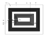
도 6a-6e는, 상이한 페라이트 재료 차폐 구조를 갖는 본 발명의 안테나의 상이한 실시예의 단면도를 도시한다.
도 7은, 본 발명의 단일 구조 안테나의 제조 공정의 실시예를 도시하는 흐름도이다.
도 8a는, 단일 권선 코일 안테나에 의해 생성된 자기장 세기의 실시예를 도시한다.
도 8b는, 2 권선 코일 안테나에 의해 생성된 자기장 세기의 실시예를 도시한다.
도 8c는, 3 권선 코일 안테나에 의해 생성된 자기장 세기의 실시예를 도시한다.
도 9는, 금속 스탬핑(stamping) 공정으로부터 제조된 2개의 코일 안테나의 실시예를 도시한다.
도 10은, 단일체(unitary body) 구조를 갖는 본 발명의 단일 구조 안테나의 제조 공정의 실시예를 도시하는 흐름도이다.
도 11은, n + 1개의 단자를 포함하는 본 발명의 단일 구조 안테나의 이론적 인 실시예를 도시한다.
도 12a 내지 도 12c는, 인덕터 코일들 사이에 상이한 전기적 접속을 제공하는 전기 스위치 구성의 다양한 실시예를 도시한다.
도 13은, 본 발명의 단일 구조 안테나를 동작시키는 실시예를 도시하는 흐름도이다.Figure 1 shows one embodiment of a prior art four-terminal two-structure dual mode antenna.
Fig. 2 shows an embodiment of a three-terminal single-structure multimode antenna of the present invention including a switch circuit.
2A is an electric circuit diagram of the 3-terminal single structure multi-mode antenna shown in FIG.
3 shows an embodiment of a three-terminal single structure multimode antenna of the present invention.
3A is an electric circuit diagram of a three-terminal embodiment of the antenna shown in Fig.
Figure 3b is an embodiment of a first layer of a multi-layer uni-structure multimode antenna of the present invention.
3C is an embodiment of a second layer of a multi-layer unifocal multimode antenna of the present invention.
Figure 3d is an enlarged view of a portion of an inductor coil having a plurality of shunt via connections.
Figure 3e is an embodiment of a three terminal single structure multimode antenna of the present invention in which each terminal is connected to a single pillar.
3F is an enlarged view showing an embodiment in which the filler of the inductor coil electrically bypasses the terminal line.
4 is an electric circuit diagram of an embodiment of the four-terminal antenna of the present invention shown in Fig.
Figure 5 shows an embodiment of a monolithic multimode antenna of the present invention including a conductive pillar having a varying width.
6A-6E show cross-sectional views of different embodiments of an antenna of the present invention having different ferrite material shielding structures.
7 is a flow chart showing an embodiment of a manufacturing process of a single structure antenna of the present invention.
Figure 8a shows an embodiment of the magnetic field strength produced by a single winding coil antenna.
Fig. 8B shows an embodiment of the magnetic field strength generated by the two-winding coil antenna.
Fig. 8C shows an embodiment of the magnetic field strength generated by a three-winding coil antenna.
Figure 9 shows an embodiment of two coil antennas fabricated from a metal stamping process.
10 is a flow chart showing an embodiment of a manufacturing process of a single structure antenna of the present invention having a unitary body structure.
11 shows a theoretical embodiment of a single structure antenna of the present invention including n + 1 terminals.
12A-12C illustrate various embodiments of an electrical switch arrangement that provide different electrical connections between inductor coils.
13 is a flowchart showing an embodiment for operating a single structure antenna of the present invention.
이하의 설명에서, 관련 기술의 철저한 이해를 제공하기 위해 다수의 특정 세부 사항이 예로서 설명된다. 그러나 당업자에게는 본 발명의 교시가 그러한 세부 사항없이 실시될 수 있다는 것이 명백할 것이다. 다른 예들에서, 공지된 방법들, 절차들, 구성 요소들 및/또는 회로들은 본 발명의 교시들의 불필요하게 모호한 것을 회피하기 위해, 세부 사항 없이 비교적 높은 수준으로 설명되었다.In the following description, numerous specific details are set forth by way of example in order to provide a thorough understanding of the related art. However, it will be apparent to those skilled in the art that the teachings of the present invention may be practiced without such detail. In other instances, well-known methods, procedures, components, and / or circuits have been described above with a relatively high level of detail, in order to avoid unnecessarily obscuring the teachings of the present invention.
본 발명의 안테나 및 그 통신 시스템은 근거리 통신과 같은 개선된 유도 통신을 제공한다. 더 구체적으로, 본 발명의 안테나는 결합 자기 공진을 가능하게 하는 단일 구조 설계로 되어있다. 결합 자기 공진은, 적절하게 설계될 때 증가된 무선 전력 전송 및 통신 효율을 제공할 수 있고, 종래 기술의 안테나의 물리적 배향 및 위치 요구에 덜 의존하는 대안 기술이다. 결과적으로, 본 발명의 안테나는 개선된 무선 전송 효율 및 더 나은 사용자 경험을 제공한다.The antenna and its communication system of the present invention provide improved inductive communication such as near field communication. More specifically, the antenna of the present invention is of a single structure design that allows coupling self-resonance. Coupled self-resonance is an alternative technique that can provide increased wireless power transmission and communication efficiency when properly designed and that is less dependent on the physical orientation and location requirements of prior art antennas. As a result, the antenna of the present invention provides improved wireless transmission efficiency and a better user experience.
또한, 본 발명의 다중 대역 단일 구조 안테나는 전송 범위를 증가시킬 수 있다. 더 상세히 논의되는 바와 같이, 본 발명의 안테나 구조는 동작 주파수의 동조를 가능하게 한다. 이는 운용자가 수신 안테나의 동작 주파수를 송신된 신호의 주파수와 정합하도록 신속하게 변경하거나, 또는 대안적으로, 수신 안테나의 증가된 동작 주파수와 정합시키기 위해 주파수 증폭기(multifier)를 사용하여 증가된 주파수에서 신호를 송신할 수 있게 한다. 또한, 본 발명의 단일 구조 안테나는 수신된 또는 송신된 신호를 조절하거나 변경할 수 있는 선택 회로를 포함할 수 있다. 그 예는 범위를 증가시키기 위해 주파수 배율 계수(frequency multiplying factor)에 의해 안테나의 동작 주파수를 변경하는 것을 포함한다.In addition, the multi-band single structure antenna of the present invention can increase the transmission range. As discussed in more detail, the antenna structure of the present invention enables tuning of the operating frequency. This allows the operator to quickly change the operating frequency of the receiving antenna to match the frequency of the transmitted signal, or alternatively, at an increased frequency using a frequency multiplier to match the increased operating frequency of the receiving antenna Signal to be transmitted. In addition, the single structure antenna of the present invention may include selection circuitry capable of modulating or modifying the received or transmitted signal. The example involves changing the operating frequency of the antenna by a frequency multiplying factor to increase the range.
또한, 본 발명의 안테나는 동작 주파수를 증가시킬 수 있다. 더 높은 주파수 범위에서 작동하면 안테나 폼 팩터(form factor)가 더 작아진다. 예를 들어, 일반 송신 및 수신 안테나 조합 모두가 거리 d만큼 이격되고 결합 계수, k를 갖는 주파수 (□□에서 작동하는 것을 고려하라. 송신 안테나에는 송신 안테나 인덕턴스(LTx)를 갖고 수신 안테나에는 수신 안테나 인덕턴스(LRx)를 갖는다. 이 시나리오에서, 수신 안테나에서의 유도 전압은 공식에 의해 주어진다:Further, the antenna of the present invention can increase the operating frequency. Operating at higher frequency ranges will result in smaller antenna form factors. Consider, for example, that both the normal transmit and receive antenna combinations are spaced apart by a distance d and operate at a frequency (□□) with a coupling coefficient, k. The transmit antenna has a transmit antenna inductance LTx, Inductance LRx. In this scenario, the induced voltage at the receive antenna is given by the formula:

위의 식을 기반으로, 동작 주파수(□□가 증가하면, 유사 결합 계수, k를 고려하면, 유사 유도 전압을 생성하는 데 요구되는 각각의 송신 및 수신 안테나 인덕턴스는 감소된다. 따라서, 결과적으로 적은 공간을 요구하는 더 적은 인덕터가 각각의 안테나를 위해 사용될 수 있다. 예를 들어, 폼 팩터, 즉, 코일의 표면적이 유사한 결합 계수를 갖도록 거의 동일하게 유지되면, 증가된 동작 주파수(□□로 인하여 감소된 수신 또는 송신 인덕턴스를 설계함으로써, 더욱 얇은 수신 코일 또는 송신 코일이 가능할 수 있다.Based on the above equation, considering the pseudo-coupling coefficient, k, when the operating frequency (□□ increases), the respective transmit and receive antenna inductances required to generate the pseudo inductive voltage are reduced. For example, if the form factor, i.e., the surface area of the coil, is kept approximately the same to have a similar coupling coefficient, an increased operating frequency (due to < RTI ID = 0.0 > By designing a reduced receive or transmit inductance, thinner receive coils or transmit coils may be possible.
공간이 중요한 위치에 있는 웨어러블 전자 장치에서, 더 높은 주파수에서 동작하고 수신 안테나의 각각의 인덕터를 의도된 송신 주파수에 더 가깝게 동조하면 증가된 성능 즉, 향상된 품질 계수 및 더 작은 폼 팩터에서 증가된 유도 전압의 가능성을 제공한다.In a wearable electronic device where space is at a critical location, operating at a higher frequency and tuning each inductor of the receive antenna closer to the intended transmit frequency results in increased performance, i.e., improved quality factor and increased induction in a smaller form factor Providing the possibility of voltage.
종래의 TSMM 안테나와는 달리, 본 발명의 단일 구조 다중 모드(SSMM) 안테나는 다른 많은 무선 전력 전송 표준뿐만 아니라 Qi 및 Rezence 인터페이스 표준을 포함하는 다수의 비 제한적인 주파수 범위의 수신 및 송신을 가능하게 하는 효율적인 설계를 제공한다. 또한, 본 발명의 단일 구조 다중 모드 안테나는 약 400MHz보다 큰 주파수에서 동작하는 다수의 주파수 표준뿐만 아니라 근거리 통신(NFC), 무선 주파수 식별(RFID), 다중 모드 표준 트랜스 폰더(MST) 등과 같은, 그러나 이것에 제안되지 않는, 다중 통신 기반 표준을 가능하게 한다. 이들 다중 "전력" 전송 및/또는 "통신" 모드의 물리적 메커니즘은 자기장과 같은 순수 자기, 전자기파와 같은 전자기, 용량성 상호 작용 또는 압전 작용과 같은 전기일 수 있다. 압전력(piezoelectric power) 전달 및/또는 통신 모드는 음향 신호를 전기 신호로 또는 음향 신호를 전기 신호로 변환할 수 있는 티탄산 바륨(barium titanate), 티탄산 지르콘산 납(lead zirconate titanate) 또는 니오브산 칼륨(potassium niobate)와 같은 독특한 압전 재료를 일반적으로 필요로 한다.Unlike conventional TSMM antennas, the single structure multi-mode (SSMM) antenna of the present invention enables reception and transmission of multiple, non-restrictive frequency ranges including many other wireless power transmission standards as well as Qi and Rezence interface standards Efficient design. In addition, the single structure multi-mode antenna of the present invention can be used for a number of frequency standards operating at frequencies greater than about 400 MHz, but also for various applications such as NFC, Radio Frequency Identification (RFID), Multi-Mode Standard Transponder (MST) Enabling multiple communication based standards that are not proposed for this. The physical mechanism of these multiple "power" transmission and / or "communication" modes may be pure magnetic, such as a magnetic field, or electromagnetic, such as electromagnetic waves, capacitive interaction or electricity. The piezoelectric power transfer and / or communication mode may be selected from the group consisting of barium titanate, lead zirconate titanate or potassium niobate, which can convert acoustic signals into electrical signals or acoustic signals into electrical signals a piezoelectric material such as potassium niobate is generally required.
특히, 본 발명의 단일 구조 다중 모드(SSMM) 안테나는 무선으로 송신된 전력 및/또는 데이터의 송신 및 수신 중 하나 또는 모두를 용이하게 한다. 본 발명의 SSMM 안테나의 독특한 설계 및 구성은 감소된 폼 팩터에서 최적의 전기적 성능을 갖는 안테나를 제공한다.In particular, the single structure multi-mode (SSMM) antenna of the present invention facilitates one or both of transmitting and receiving wirelessly transmitted power and / or data. The unique design and construction of the SSMM antenna of the present invention provides an antenna with optimal electrical performance in a reduced form factor.
또한, 본 발명의 단일 구조 안테나는 복수의 코일의 인접 와이어 가닥들로부터의 자기장을 차단하기 위해 다양한 페라이트 물질과 같은 복수의 물질을 또한 포함할 수 있다. 따라서, 이들 자기 차단 물질은 전력 및/또는 전기 신호의 전파에 대한 자기장의 악영향으로부터 인접한 와이어 가닥을 보호한다.The single structure antenna of the present invention may also include a plurality of materials, such as various ferrite materials, to block the magnetic field from adjacent wire strands of a plurality of coils. Thus, these magnetic shielding materials protect adjacent wire strands from adverse influences of the magnetic field on the propagation of power and / or electrical signals.
구체적으로, 본 발명은 다수의 인덕터 코일이 전기적으로 직렬로 접속된 단일 코일 구조를 갖는 안테나를 제공한다. 이러한 구성은 안테나 내에서 인덕턴스의 조정 또는 동조을 가능하게 하는 콤팩트 한 디자인을 갖는 안테나를 제공하여 다중 안테나 주파수를 동조할 수 있게 한다.Specifically, the present invention provides an antenna having a single coil structure in which a plurality of inductor coils are electrically connected in series. This arrangement provides an antenna with a compact design that allows tuning or tuning of the inductance in the antenna, allowing tuning of multiple antenna frequencies.
이제 도면을 참조하면, 도 2, 도 2a, 도 3a, 도 3b, 도 3c, 도 3d, 도 3e, 도 4, 도 4a 및 도 11은 본 발명의 단일 구조 다중 모드 안테나의 상이한 실시예 및 구성을 나타낸다. 도 2는 본 발명의 3 단자 안테나(20)의 실시예를 도시한다. 도시된 바와 같이, 안테나(20)은 제 1, 외부 코일(24) 및 제 2, 내부 코일(26)이 위치된 기판(22)을 포함한다. 더 상세하게는, 제 1 및 제2 코일(24, 26) 모두는 기판(22)의 외부 표면(28)상에 위치 된다. Referring now to the drawings, FIGS. 2, 2A, 3A, 3B, 3C, 3D, 3E, 4, 4A and 11 illustrate different embodiments of the inventive single- . 2 shows an embodiment of a three-
도시된 바와 같이, 제 1 외부 코일(24)은 기판(22)의 표면(28)에 대해 곡면 배향으로 위치된 트레이스 또는 필라와 같은 제 1 전기 전도성 물질(30)을 포함한다. 바람직한 실시예에서, 트레이스 또는 필라는 "N1" 권선수를 갖는 기판(22)의 표면(28)에 대해 나선형 또는 사(蛇)형(serpentine) 배향으로 위치된다. 제 2 내부 코일(26)은 기판(22)의 표면(28)에 대해 만곡된 배향으로 배치된 트레이스 또는 필라와 같은 제 2 전기 도전성 물질(32)을 포함한다. 바람직한 실시예에서, 제 2 트레이스 또는 필라(32)는 "N2" 권선수를 갖는 기판(22)의 표면(28)에 대해 나선형 또는 사형 배향으로 위치한다.As shown, the first
도 2에 도시된 바와 같은 바람직한 실시예에서, 제 2 내부 코일(26)은 제 1 외부 코일(24)에 의해 형성된 내주연(perimeter) 내에 위치된다. 본 명세서에 정의된 바와 같이, "권선"은 기판의 표면상에 위치된 전기 전도성 필라의 단일의(single) 완전한 원주 회전이다. 도 2에 도시된 예시적인 안테나에서 도시된 바와 같이, 제 1 외부 코일(24)은 3 권선(N1)을 포함하고, 제 2 내측 코일(26)은 14 권선(N2)을 포함한다. 바람직한 실시예에서, 제 1 외부 코일(24)은 약 1 내지 500 이상의 다수의 "N1" 권선을 포함할 수 있고, 제 2 내부 코일(26)은 약 1 내지 1,000 이상의 다수의 "N2" 권선을 포함할 수 있다. 바람직한 실시예에서, "N2" 권선수는 "N1" 권선수보다 크다. 또한, 제 1 및 제 2 코일(24, 26)을 별개의 권선을 갖도록 구성할 필요는 없으며, 또한, 코일(24, 26)을 완전한 권선의 1/2 권선 또는 1/4 권선과 같은 부분 권선을 갖도록 구성할 수 있다.In the preferred embodiment as shown in FIG. 2, the second
또한, 제 1 외부 유도 코일(24)을 형성하는 전도성 필라(30)는 약 0.01mm 내지 약 20mm 범위의 필라 폭을 갖는다. 바람직한 실시예에서, 외부 인덕터 코일 필라(30)의 폭은 일정하다. 그러나 제 1 외부 인덕터 전도성 필라(30)의 폭은 변할 수있다. 제 2 내부 유도 코일(26)을 형성하는 전도성 필라(32)는 약 0.01mm 내지 약 20mm 범위의 바람직한 폭을 갖는다. 또한, 제 2 도전성 필라(32)는 일정하거나 가변 폭을 갖도록 구성될 수 있다. 바람직한 실시예에서, 제 1 외부 인덕터 코일(24)을 형성하는 제 1 전기 전도성 필라(30)는 제 2 내부 인덕터 코일(26)을 형성하는 제 2 전기 전도성 필라(32)의 폭보다 큰 폭을 갖는다. 그러나 제 1 전도성 필라(30)의 폭은 제 2 내부 인덕터 코일(26)을 형성하는 제 2 전기 전도성 필라(32)의 폭과 거의 같거나 더 좁을 수있다.In addition, the
일반적으로, 제 1 외부 인덕터 코일(24)은 MHz 범위의 보다 높은 주파수의 수신 및/또는 송신에 기여하는 반면, 제 2 내부 인덕터 코일(26)은 kHz 범위의 주파수의 수신 및/또는 송신에 기여한다. 제 1 외부 인덕터 코일(24)을 포함하는 증가된 둘레 크기 및 전형적으로 더 적은 수의 필라 권선은 일반적으로 4.2μH 범위의 제 1 코일 인덕턴스를 생성하고, 따라서 MHz 동작 주파수 범위에서 수신 및/또는 송신을 제공한다. 대조적으로, 제 2 내부 인덕터 코일(26)의 증가된 필라 권선수 및 더 작은 코일 직경은 일반적으로 8.2μH 범위의 인덕턴스를 생성하며, 이는 kHz 동동 주파수 범위에서 수신 및/또는 송신을 제공한다. 또한, 적어도 제 1 및 제 2 인덕터 코일(24, 26)을 서로 다른 위치에서 직렬로 전기적으로 접속함으로써, 본 발명의 단일 구조 안테나는 감소된 표면적 및 더 작은 차지하는 공간을 포함하면서 다중 주파수에서 동작할 수 있다.In general, the first
구체적으로, 본 발명의 단일 구조 안테나는 제 1 및 제 2 인덕터 코일(24, 26)에 각각 전략적으로 위치하는 복수의 단자 접속을 포함한다. 이 고유한 안테나 설계는 다양한 동조 가능한 인덕턴스를 제공하여, 결과적으로 다양한 선택 가능 동조 가능한 동작 주파수를 제공한다. 바람직한 실시예에서, 단일 구조 안테나는 약 1kHz 범위 내지 약 10GHz 범위의 다중 주파수 및 다중 주파수 대역에서 동작할 수 있도록 설계될 수 있다. 종래 기술의 2 구조 안테나(10)는 이와 같이 감소된 차지하는 공간 크기를 갖는 다중 주파수에서 동작할 수 없다.Specifically, the single structure antenna of the present invention includes a plurality of terminal connections strategically located in the first and second inductor coils 24, 26, respectively. This unique antenna design provides a variety of tunable inductances, resulting in a wide variety of selectable tunable operating frequencies. In a preferred embodiment, a single structure antenna can be designed to operate in multiple frequencies and multiple frequency bands ranging from about 1 kHz to about 10 GHz. The prior art two-
도 2는 본 발명의 3 단자 단일 구조 안테나(20)의 일례를 나타낸다. 도 2에 도시된 바와 같이, 제 1 외부 코일(24)은 제 2 내부 코일(26)에 직렬로 전기적으로 접속된다. 2개의 코일(24, 26) 사이의 이러한 전기적 접속은 감소된 차지하는 공간에서 양 코일의 인덕턴스 기여(contribution) 및 그 부분을 겸비한다. 도 2a는 도 2에 도시된 안테나(20)의 전기 회로도이다. 도시된 바와 같이, 안테나(20)는 제 1 단자(34), 제 2 단자(36) 및 제 3 단자(35)의 3 단자를 포함한다. 도시된 바와 같이, 제 1 단자(34)는 제 1 외부 유도 코일(24)에 전기적으로 접속되고, 제 2 단자(36)는 제 2 내부 유도 코일(26)에 전기적으로 접속되고, 제 3 단자(35)는 제 1 외부 코일(24)의 제 2 단부에 전기적으로 접속된다. 대안으로, 안테나(20)는 제 1 유도 코일(24)에 전기적으로 접속된 제 2 단자(36) 및 제 2 유도 코일(26)에 전기적으로 접속된 제 1 단자(34)를 갖도록 구성될 수 있다.2 shows an example of a three-terminal
바람직한 실시예에서, 안테나(20)는 원하는 인덕턴스 및 동작 주파수의 선택을 가능하게 하는 전기 스위치 회로(37)를 갖도록 구성될 수 있다. 보다 구체적으로, 전기 스위치 회로(37)는 제 1 및 제 2 코일(24, 26) 중 하나 또는 이들의 조합의 전기 임피던스의 검출 및 분석을 가능하게 한다. 따라서, 전기 임피던스의 검출 및 분석에 기초하여, 안테나의 동작 주파수의 효율적인 선택은 최적화되거나 원하는 전기 임피던스 값에 기초하여 달성될 수 있다. 또한, 단자 접속의 선택은 원하는 동작 주파수 또는 주파수들에서 최적화되거나 원하는 인덕턴스 값에 기초할 수 있다.In a preferred embodiment, the
도 2에 도시된 바와 같이. 스위치 회로(37)는 제 1 및 제 2 코일(24, 26) 사이에서 직렬로 전기적으로 접속된다. 바람직한 실시예에서, 스위치 회로(37)는 제 1 및 제 2 코일(24,26) 사이의 접속을 선택할 수 있거나, 또는 대안적으로, 제 1 또는 제 2 코일(24, 26) 중 어느 하나를 개별적으로 선택할 수 있다. 제 3 단자(35)는 제 1 및 제 2 코일(24, 26) 사이의 전기적 접합인 포인트(33)에서 전기적으로 접속된다.As shown in FIG. The
전술한 바와 같이, 전기 스위치 회로(37)는 제 1 커패시턴스를 갖는 적어도 하나의 커패시터(C1)를 포함하는 것이 바람직하다. 적어도 하나의 커패시터(C1)는 제 3 단자(35)와 전기적으로 접속되는 것이 바람직하다. 또한, 스위치(37)는 제 2 커패시턴스를 갖는 제 2 커패시터(C2)를 포함할 수 있다. 제 2 캐패시터(C2)는 포인트(33)와 제 2 내부 코일(26) 사이에 접속되는 것이 바람직하다. 적어도 하나의 캐패시터(C1)의 포함은 동작 주파수에서 코일(24, 26)의 어느 하나 또는 양쪽의 임피던스의 검출 및 분석을 가능하게 한다. 바람직한 실시예에서, 전기 임피던스는 다음 식: X = 2πfL에 의해 결정될 수 있다. 여기서, X는 안테나의 전기 임피던스이고, f는 안테나의 동작 주파수이고, L은 안테나의 인덕턴스이다.As described above, the
바람직한 실시예에서, 기판(22)은 굽힘 및 기계적 굴곡이 가능한 가요성 형태이다. 기판(22)은 전기 절연 물질로 구성되는 것이 바람직하다. 이러한 절연 물질의 예로는, 종이, 폴리미드(polymide), 아크릴(acrylic) 또는 카톤(Kapton), 유리 섬유(fiberglass), 폴리에스테르(polyester), 폴리에테르 이미드(polyether imide), 폴리테트라플루오로에틸렌(polytetrafluoroethylene), 폴리에틸렌(polyethylene), 폴리에테르에테르케톤(polyetheretherketone(PEEK)), 폴리에틸렌 나프탈레이트(polyethylene napthalate), 플루오로 중합체(fluropolymer), 공중합체(copolymers)와 같은 중합체 물질(polymeric material), 알루미나(alumina)와 같은 세라믹 물질, 이들의 합성체(composites), 또는 이들의 조합을 포함하나 이들에 한정되지 않는다. 어떤 상황(예를 들어, 안테나가 자석 와이어/리츠(litz) 와이어 또는 스탬된(stamped) 금속과 같은 절연 와이어를 사용하여 구성되는 경우)에서, 기판은 차폐 물질일 수 있다.In a preferred embodiment, the
바람직한 실시예에서, 안테나(20)의 제 1, 제 2 및 제 3 단자(34, 36, 35) 중 적어도 하나는 전자 장치(38)에 전기적으로 접속 가능하다. 전기 장치(38)는 안테나(20)에 의해 수신되거나 또는 송신된 전력, 전압, 전류 또는 전자 데이터 신호를 변경 및/또는 조절하는데 사용될 수 있다. 안테나에 의해 수신된 전기 에너지는 전자 장치(38)에 직접 전력을 공급하는 데 사용될 수 있다. 대안으로, 전기 장치(38) 전력 및/또는 그 데이터 신호를 송신하는데 사용될 수 있다. 전자 장치(38)는 동조 또는 매칭 회로(도시되지 않음), 정류기(도시되지 않음), 전압 조정기(도시되지 않음), 전기 저항 로드(도시되지 않음), 전기 화학적 셀(도시되지 않음) 또는 이들의 조합 포함할 수 있으나, 이들에 제한되지 않는다.In a preferred embodiment, at least one of the first, second and
도 3은 본 발명의 3 단자 단일 구조 안테나(40)의 추가 실시예를 도시한다. 도 2에 도시된 안테나(20) 실시예와 유사하게, 3 단자 안테나(40)는 제 2 내부 코일(44)에 직렬로 전기적으로 접속된 제 1 외부 코일(42)을 포함한다. 2개의 코일(42, 44) 사이의 전기적 접속은 감소된 크기 및 표면적에 각각의 코일(42, 44)의 인덕턴스 기여를 겸비한다. 제 3 단자의 추가는 안테나(40)가 특정 주파수 또는 다중 주파수 대역들로 동조될 수 있게 한다. 따라서, 외부 및 내부 인덕터 코일(42, 44) 사이 및 내부에 다수의 접속을 제공함으로써, 인덕터를 추가하거나 또는 제거할 필요없이 인덕턴스, 즉 수신 또는 송신 주파수 대역을 순간적으로 조정할 수 있다. 3 단자 안테나 설계는 제 1 및 제 2 코일(42, 44)이 제 1 및 제 2 코일(42, 44) 중 하나 또는 둘 모두를 따라 상이한 위치에서 전략적으로 접속되게 한다. 결과적으로, 안테나(40)의 인덕턴스가 변경될 수 있다. 즉, 안테나가 차지하는 공간의 크기를 증가시키지 않고 증가 또는 감소시킬 수 있다. 본 발명의 안테나(40)는 그 내부의 공간 및 기판 표면 크기를 효율적으로 이용하여 인덕턴스를 증가 및/또는 감소시키고, 따라서 안테나(40)의 동작 주파수 또는 주파수 대역을 커스텀 동조할 수 있다.FIG. 3 illustrates a further embodiment of a three-terminal
도 3에 도시된 바와 같이, 안테나(40)는 3개의 단자 접속(52, 54 및 56)을 각각 갖는 3개의 단자, 즉 제 1 단자(46), 제 2 단자(48) 및 제 3 단자(50)를 포함한다. 각 단자는 안테나(40)의 상이한 단자 접속점에서 전기적으로 접속된다. 도시된 바와 같이, 제 1 단자(46)는 제 1 외부 코일(42)의 제 1 트레이스(60)의 제 1 단부(58)로부터 연장한다. 제 2 단자(48)는 제 2 인덕터(44)의 제 2 트레이스(64)의 제 1 단부(62)로부터 연장한다. 제 3 단자(50)는 제 2 코일(44)의 제 2 트레이스(64)의 제 2 단부(66)로부터 연장한다. 따라서, 3개의 단자(46, 48 및 50)는 제 1 및 제 2 인덕터 코일(42, 44)과 그 일부 사이에 상이한 접속점을 제공한다.3, the
따라서, 상이한 조합으로 다양한 단자를 접속함으로써, 본 발명의 안테나(40)는 결과적으로, 안테나(40)의 동작 주파수 또는 동작 모드를 변경시키는 상이한 조정 가능한 인덕턴스를 제공한다. 예를 들어, 제 1 단자(46)를 제 2 단자 (48)에 전기적으로 접속함으로써, 제 1 동작 주파수에서의 동작에 일반적으로 적합한 제 1 인덕턴스가 생성될 수 있다. 제 1 단자(46)를 제 3 단자(50)에 전기적으로 접속하는 것은 제 2 동작 주파수에서의 동작에 일반적으로 적합한 제 2 인덕턴스를 생성한다. 제 2 단자(48)를 제 3 단자(50)에 전기적으로 접속하는 것은 제 3 동작 주파수에서의 동작에 일반적으로 적합한 제 3 인덕턴스를 생성한다. 본 발명의 안테나에 의해 생성될 수 있는 각각의 인덕턴스는 바람직하게는 서로 상이하다. 또한, 안테나는 순간적으로 하나의 인덕턴스 값을 다른 인덕턴스 값으로 스위칭할 수 있어, 안테나의 동작 주파수를 순간적으로 변화시킬 수 있다는 것이 고려된다. Thus, by connecting the various terminals in different combinations, the
도 3a는 도 3에 도시된 3 단자 안테나(40)의 전기 회로도를 도시한다. 도시된 바와 같이, 제 1 단자(46)와 제 3 단자(50)를 접속하는 것은 "N1" 권선수를 갖는 제 1 외부 인덕터 코일(42)에 접속을 제공한다. 제 2 단자(48)를 제 1 단자(46)에 접속하는 것은 "N2" 권선수를 갖는 제 2 내부 인덕터 코일(44)에 접속을 제공한다. 마지막으로, 제 2 및 제 3 단자(48, 50) 사이의 접속을 설정함으로써, "N1" + "N2" 턴을 갖는 제 1 외부 인덕터 코일(42) 및 제 2 내부 인덕터 코일(44) 모두에 대한 전기적 직렬접속을 제공한다. 보다 구체적으로, 도 3a는 제 1 인덕터 코일(42)은 제 2 인덕터 코일(44)과 직렬로 전기적으로 접속된다. 도시된 바와 같이, 제 1 단자(46)는 제 1 외부 인덕터 코일(42)의 제 1 단부(58)에 전기적으로 접속된다. 제 2 단자(48)는 제 1 인덕터 코일 제 1 단부(58)의 말단 전기 접속(68)에서 제 2 인덕터 코일(44)의 제 1 단부(62)에 전기적으로 접속된다. 도시된 바와 같이, 제 3 단부(50)은 제 1 인덕터 코일(42)의 제 2 단부(70)에 전기적으로 접속된다.Fig. 3A shows an electric circuit diagram of the three-
바람직한 실시예에서, 도 3 및 도 3a에 도시된 3 단자 안테나 설계는, 3가지 상이한 동작 모드에서 안테나의 동작을 가능하게 한다. 본 명세서에서 정의된 바와 같이, 동작 모드는 동작 주파수 대역폭이다. 이러한 모드에는 Qi, PMA 및 Rezence 무선 표준 주파수가 포함될 수 있지만 이에 국한되지는 않는다. 다음 표 1은 다양한 단자 접속 구성의 예와 해당 구성 요소가 안테나 동작 모드에 미치는 영향을 설명한다. 보다 구체적으로, 표 1은 다양한 단자 접속을 함께 접속함으로써 안테나의 동작 주파수가 어떻게 변경될 수 있는지에 대한 다양한 예를 도시한다. 표 1에 설명된 동작 주파수는 예이며, 동작 주파수 대역은 특정 요건을 충족시키기 위해 맞춤화된 것일 수 있다. 이러한 맞춤(customization)은 특정 권선수, 특정 트레이스 폭, 및 제 1 및 제 2 코일 각각의 단자 위치 점을 갖는 각 코일을 설계함으로써 달성할 수 있다.In the preferred embodiment, the three-terminal antenna design shown in Figures 3 and 3A enables operation of the antenna in three different modes of operation. As defined herein, the operating mode is the operating frequency bandwidth. These modes may include, but are not limited to, Qi, PMA, and Rezence wireless standard frequencies. The following Table 1 shows examples of various terminal connection configurations and their effect on the mode of operation of the antenna. More specifically, Table 1 shows various examples of how the operating frequency of an antenna can be changed by connecting various terminal connections together. The operating frequency described in Table 1 is an example, and the operating frequency band may be tailored to meet specific requirements. This customization can be achieved by designing each coil with a specific winding width, a specific trace width, and a terminal position point of each of the first and second coils.
한편, 도 3 및 도 3a는 3개의 단자를 제 1 및 제 2 인덕터 코일(42, 44)의 각각의 단부에 접속하는 특정 예를 도시하지만, 이들 접속은 제 1 및 제 2 인덕터 코일(42, 44)의 제 1 및 제 2 도전성 트레이스(60, 64)를 따라 다양한 전기 전도점에 위치될 수 있다는 것이 추가로 고려된다. 또한, 추가의 단자 접속은 안테나(40)의 제 1 및 제 2 인덕터 코일(42, 44)을 따라 위치되어, 커스터마이즈된 인덕턴스를 추가로 제공할 수 있고, 따라서 커스터마이즈된 동작 주파수를 안테나(40)에 제공할 수 있는 것이 고려된다. 일반적으로, 증가된 권선수를 갖는 인덕터 코일 또는 다중 인덕터 코일과의 전기적 접속을 설정하면 인덕턴스가 증가되어, 더 낮은 주파수 신호를 수신 또는 송신하기에 더 적합한 안테나가 된다. 마찬가지로, 감소된 권선수를 갖는 인덕터 코일 또는 다중 인덕터 코일과의 전기적 접속을 설정하면 인덕턴스가 감소되고, 따라서 더 높은 주파수의 신호를 수신하거나 송신하는데 더 적합한 안테나가 된다.3 and 3A illustrate a specific example of connecting three terminals to the respective ends of the first and second inductor coils 42 and 44, but these connections can be made between the first and second inductor coils 42, 44 may be located at various electrical conduction points along the first and second conductive traces 60, 64. Additional terminal connections may also be located along the first and second inductor coils 42 and 44 of the
도 2 및 도 2a에 도시된 2 단자 안테나와 유사하게, 3 단자 안테나는 전기 장치(38)에 전기적으로 접속될 수 있다. 전기 장치(38)는 전력 및/또는 디지털 데이터 신호와 같은 전기 신호를 조절 또는 변경하도록 설계될 수 있다. 대안적으로, 전기 장치(38)는 전력 및/또는 데이터 신호를 직접 수신하거나 또는 송신할 수 있다. 전자 장치(38)는 동조 또는 매칭 회로(도시되지 않음), 정류기(도시되지 않음), 전압 조정기(도시되지 않음), 전기 저항 부하(도시되지 않음), 전기 화학적 셀(도시되지 않음) 또는 이들의 조합을 포함할 수 있으나 이들에 제안되지 않는다. 전자 장치(38)는 수신된 전압, 전류 또는 디지털 신호를 변경 또는 조절하는 것뿐만 아니라, 안테나(40)에 의해 송신되는 전압, 전류 또는 디지털 신호를 변경 또는 조절하는데 사용될 수 있다.Similar to the two-terminal antenna shown in Figs. 2 and 2A, the three-terminal antenna can be electrically connected to the
도 3b 및 도 3c는 다층 3 단자 안테나(72)의 실시예를 도시하고 있다. 바람직한 실시예에서, 본 발명의 단일 구조 안테나는 서로 평행 배향으로 위치된 복수의 2개 이상의 기판 층(22)을 포함할 수 있다. 또한, 적어도 하나의 전기 전도 트레이스가 안테나(72)를 포함하는 기판의 외부 표면을 따라 위치된다. 적어도 하나의 인덕터 코일이 하나 이상의 기판의 상부 표면을 따라 배치되도록 필라 또는 필라들을 배향시킬 수 있다. 안테나를 포함하는 기판은 바람직하게는 제 1 기판의 하부 표면이 제 2 기판의 상부 표면 위에 위치되도록 동일한 배향으로 배향된다.3B and 3C illustrate an embodiment of a multi-layer three-
또한, 적어도 하나의 비아(via)가 다양한 기판 층들 사이에 전기적 접속을 형성하도록 제공될 수 있다. 바람직한 실시 예에서, 적어도 하나의 비아는 상이한 기판 층에 인덕터 코일 또는 코일들을 포함하는 필라 또는 필라의 부분 사이의 전기적 접속을 제공한다. 본 명세서에 정의된 바와 같이, "비아(via)"는 2개 이상의 기판 층들 사이의 전기적 접속이다. 비아는 와이어, 전기적으로 메워지는(filled) 관통 보어(through-bore) 또는 전기 도전성 트레이스를 포함할 수 있다.Also, at least one via may be provided to form an electrical connection between the various substrate layers. In a preferred embodiment, the at least one via provides electrical connection between portions of the pillar or pillar including the inductor coil or coils in different substrate layers. As defined herein, a "via" is an electrical connection between two or more substrate layers. Vias may include wires, filled through-bores, or electrically conductive traces.
구체적으로, 도 3b 및 도 3c는 2층 3 단자 단일 구조 안테나의 제 1 및 제 2 층을 각각 도시한다. 도 3b는 본 발명의 안테나(72)의 제 1 또는 하부 층(74)의 실시예를 도시한다. 도시된 바와 같이, 제 1 층(74)은 제 2 내부 유도 코일(78)에 전기적으로 직렬로 접속된 제 1 외부 유도 코일(76)을 포함한다.3B and 3C show the first and second layers of a two-layer, three-terminal single-structure antenna, respectively. Figure 3B illustrates an embodiment of a first or
바람직한 실시예에서, 도 3b에 도시된 바와 같이, 제 1 단자(46)는 2개의 트레이스 또는 필라에 전기적으로 병렬로 접속되어, 제 1 인덕터 코일(76)을 포함하는 바이필라(bifilar) 접속(80)을 생성한다. 유도 코일을 포함하는 2개 이상의 인접한 전기 전도 트레이스 또는 필라는 병렬로 접속될 수 있음을 주목한다. 일반적으로 2개 이상의 인접한 트레이스 또는 필라를 접속하면 전기 저항, 특히 안테나의 등가 직렬 저항(ESR)이 감소되어 결과적으로, 안테나의 품질 계수가 향상됩니다.In a preferred embodiment, the
도 3b에 도시된 바와 같이, 제 1 인덕터 코일(76)은 제 1 인덕터 코일(76)에 의해 형성된 내주연 내부에 위치된 제 2 내부 인덕터 코일(78)에 전기적으로 직렬 접속된다. 도시된 바와 같이, 코일(76)의 내부 가장 말단에 위치한 제 1 인덕터 코일 코일(76)의 제 2 단부(82)는 제 2 인덕터 코일(78)의 제 1 단부(84)에 전기적으로 접속된다. 내부 인덕터 코일(78)의 제 1 단부(84)는 제 2 인덕터 코일(78)의 가장 외부 필라 트랙의 단부에 배치된다, 제 2 인덕터 코일(78)은 제 2 인덕터 코일(78)의 가장 내측 위치에 배치된 제 2 인덕터 코일 제 2 단부(86)에서 끝난다.3B, the
도 3c는 본 발명의 안테나(72)의 제 2 상부 기판 층(88)의 실시예를 도시한다. 제 2 층(88)은 제 1 하부 기판(74) 바로 위에 위치되는 것이 바람직하다. 제 2 층(88)은 제 4 내부 인덕터 코일(92)에 전기적으로 직렬로 접속된 제 3 외부 인덕터 코일(90)을 포함한다.3C illustrates an embodiment of a second
바람직한 실시예에서, 각각의 제 1 및 제 3 코일(76, 90) 및 제 1 및 제 2 층(74, 88)의 제 2 및 제 4 코일(78, 92)은 그들 각각의 기판에 대해 병렬 관계로 위치될 수 있다. 또한, 각각의 제 1 및 제 3 코일(76, 90) 및 제 1 및 제 2 층(74, 88)의 제 2 및 제 4 코일(78, 92)은 그들 각각의 기판 표면에 대해 유사한 위치에있을 수 있고 유사한 트레이스 폭을 가지는 동일한 권선수를 포함할 수 있다. 대안적으로, 각각의 제 1 및 제 3 코일(76, 90) 및 제 1 및 제 2 층(74, 88)의 제 2 및 제 4 코일(78, 92)은 그들의 특정 기판 표면에 대해 상이한 위치에 위치될 수 있고, 그들은 상이한 트레이스 폭을 갖는 상이한 권선수를 가질수 있다. In a preferred embodiment, each of the first and
제 1 층(74)과 유사하게, 제 2 층(74)의 제 1 단자(46)는 인접한 두 개의 트레이스 또는 필라에 전기적으로 병렬 접속되어, 제 3 인덕터 코일(90)의 제 1 단부(94)에 바이필라를 생성시킬 수 있다. 이 바이필라 접속은 제 3 인덕터 코일 (90)의 전기적 트레이스 패턴을 포함하고, 제 3 코일(90) 둘레로 연장되어 그 제 2 단부(96)에서 끝난다. 또한, 제 3 인덕터 코일(92)은 제 3 인덕터 코일(90)의 내부 위치에 배치된 제 3 인덕터 코일 단부(96)에서 제 3 인덕터 코일(90)의 내주연 내에 위치된 제 4 내부 인덕터 코일(92)에 전기적으로 직렬로 접속된다. 제 4 인덕터 코일(92)의 가장 맨 외부 필라 트랙에 배치된 내부 인덕터 코일의 제 1 단부(98)에서 제 3 인덕터 코일(90)에 전기적으로 접속된다. 또한, 도 3c에 도시된 바와 같이, 제 2 상부 층(88)은 제 2 및 제 3 단자 접속(48, 50)을 또한 포함한다. 바람직한 실시예에서, 제 2 단자(48)는 제 4 코일(92)의 가장 맨 내부 위치에 배치된 제 4 인덕터 코일(92)의 제 2 단부(100)에서 전기적으로 접속된다. 또한, 제 2 단자(48)의 길이는 제 3 및 제 4 인덕터 코일(90, 92)을 포함하는 각각의 필라 트랙으로부터 전기적으로 격리된다. 제 3 단자(50)는 제 2 상부 층(88)상에 제공된다. 도시된 바와 같이, 제 3 단자(50)는 제 3 외부 인덕터 코일(90)의 가장 맨 내부 위치에 배치된 바이필러 트랙(94)에 전기적으로 접속된다.Similar to the
또한, 비아(102) 또는 복수의 비아(102)는 본 발명의 단일 구조 안테나(72)를 포함하는 2개 이상의 기판 층(74, 88) 사이에 위치되는 것이 바람직하다. 더욱 바람직하게는, 적어도 하나의 비아(102)는 전기적 성능 및 품질 계수에 악영향을 미칠 수 있는 전기 저항을 최소화하기 위해 각각의 제 1 및 제 3 인덕터 코일(76, 90) 또는 제 2 및 제 4 인덕터 코일(78, 92) 사이의 상이한 위치 사이에서 분로(shunted) 전기 접속을 제공한다.It is also preferred that the
바람직한 실시예에서, 제 2 및 제 3 단자(48, 50)의 부분을 전기적으로 격리하기 위해 복수의 분로된 비아 접속은 상부 및 하부 층 사이에 위치됨으로써, 단자가 각각의 코일의 도전성 트레이스를 "오버 패스"할 수 있다. 보다 구체적으로, "오버 패스"를 생성하기 위해, 복수의 비아들(102)이 단자의 트레이스(104)의 각각의 좌측 및 우측에 위치될 수 있다. 따라서, 단자의 단자 라인(104)의 각각의 좌 및 우측에 위치된 다수의 비아들(102)은 단자 트레이스(104) 아래에 전기 경로를 형성함으로써, 단자 리드(104)가 위치한 유도성 트레이스의 부분을 "바이 패싱" 시킴으로써 단자 트레이스(104)를 전기적으로 격리시킨다. 이 실시예에서, 복수의 비아(102) 각각은 각각의 좌 및 우측 단자 리드(104)에 대해 서로 반대로 위치된다.In a preferred embodiment, a plurality of shunted via connections are positioned between the upper and lower layers to electrically isolate portions of the second and
도 3d는 하부 제 1 기판 층(74)상에 배치된 제 1 인덕터 코일(76)의 부분과 상부 제 2 기판 층(88)상에 배치된 제 3 인덕터 코일(90) 사이의 복수의 분로 비아 접속의 일례의 확대도이다. 도시된 바와 같이, 각각의 상부 및 하부 기판 층(74, 88)상에 배치된 인덕터 코일들 사이에 복수의 비아 접속이 도시되어있다. 보다 구체적으로, 도 3d의 실시예에 도시된 바와 같이, 단자 라인(104)의 각각의 우측 및 좌측면 각각 외에 각각의 필라 트랙을 따라 4개의 비아(102)가 위치된다. 바람직한 실시 예에서, 비아 접속은 단자 라인(104) 아래를 통과함으로써 분로된 전기 접속을 제공한다. 따라서, 단자 라인(104)의 각 측면에 인접하여 복수의 비아를 위치시킴으로써, 단자의 단자 라인(104)을 바이패스하여 단자 트레이스(104)가 그것이 통과하는 도전성 트레이스로부터 전기적으로 격리되도록 하는 전기 접속이 제공될 수있다. 또한, 인덕터 코일을 포함하는 각각의 필라 트랙을 따라 위치된 복수의 비아(102)를 제공함으로써, 본 발명의 단일 구조 안테나의 인덕턴스 및 결과적인 동작 주파수를 추가로 조정할 수 있는 다양한 전기 접속이 이루어질 수 있다. 예를 들어, 전기적으로 격리된 다양한 단자 접속을 인덕터 코일 전체에 걸쳐 위치할 수 있으므로 인덕턴스 및 동작 주파수를 추가로 맞춤 설정할 수 있다.Figure 3d illustrates a portion of the
도 3e는 각각의 제 1 및 제 2 유도 코일(108, 110)이 단일 필라 패턴을 포함하는 단일 구조 안테나(106)의 다른 실시예를 도시한다. 도시된 바와 같이, 제 1, 제 2 및 제 3 단자(46, 48 및 50)는 각각 제 1 및 제 2 인덕터 코일(108, 110)을 포함하는 단일 필라에 접속된다. 도 3b 및 도 3c에 도시된 제 1 단자 접속부와 같이, 전기 저항을 최소화하기 위해, 각각의 단자를 다중 필라에 접속하는 것이 바람직하지만, 비교적 작은 공간 및/또는 표면적에서 원하는 인덕턴스를 달성하기 위해 단일 필러에 전기 접속을 제공할 필요가 있을 수 있다. 일반적으로, 두 개 이상의 인접하게 위치한 필라에 전기적으로 병렬 접속하면 전기 저항이 감소하여 결과적으로 안테나의 품질 계수가 증가한다.Figure 3E illustrates another embodiment of a
도 3f는 도 3e에 도시된 단자 접속의 확대도이다. 도시된 바와 같이, 제 2 및 제 3 단자(48, 50)의 단자 트레이스는 인덕터 코일을 포함하는 전기적으로 도전성 필라 트랙을 거쳐 효율적으로 바이패스시킴으로써 전기적으로 격리된다. 각각의 단자 라인(104)의 양측에 제공된 비아 접속(103)은 단자 라인을 우회하여 인덕터 코일을 포함하는 필라 라인으로부터 단자 라인을 전기적으로 격리시키는 전기 접속을 제공한다. 도시된 바와 같이, 복수의 비아들(102A)은 제 3 단자(50)의 단자 리드(104)의 우측에 위치되고, 비아들(102B)은 각각의 제 3 단자(50) 및 제 2 단자(48)의 단자 트레이스들(104)의 좌측 및 우측에 위치되고, 버어들(102C)는 제 1 단자(48)의 단자 트레이스의 좌측에 위치된다.Fig. 3F is an enlarged view of the terminal connection shown in Fig. 3E. As shown, the terminal traces of the second and
본 출원에서 예시된 2 및 3 단자 안테나들에 추가하여, 단일 구조 안테나는 4개 이상의 단자 접속을 포함할 수 있다는 것이 추가로 고려된다. 도 4는 본 발명의 4 단자 안테나(112)의 실시예의 전기 회로도를 도시한다. 도시된 바와 같이, 제 1 단자(46)는 제 1 외부 인덕터 코일(42)의 제 1 단부(58)에 전기적으로 접속된다. 제 2 단자(48)는 제 2 인덕터 코일(44)의 제 1 단부에 전기적으로 접속된다. 제 3 단자(50)은 제 1 인덕터 코일(42)의 제 2 단부(70)에 전기적으로 접속된다. 또한, 제 4 단자(114)는 제 1 인덕터 코일(42)의 전기 전도성 트랙을 따라 제 2 포인트(116)에 전기적으로 접속된다. 제 4 단자 접속은 제 1 인덕터 코일(42)의 길이 및/또는 전기 접속 사이의 권선수를 효과적으로 단축시킴으로써, 안테나의 인덕턴스 및 동작 주파수를 조정하도록 선택될 수 있는 추가적인 단자 접속을 제공한다.In addition to the two and three terminal antennas illustrated in this application, it is further contemplated that a single structure antenna may include more than four terminal connections. 4 shows an electrical circuit diagram of an embodiment of a four
아래에 도시된 표 2는 도 2, 도 2a, 도 3a, 도 4 및 도 4b에 도시된 예시적인 3 및 4 단자 접속 안테나의 인덕턴스 및 결과 동작 주파수를 상술한다. 인덕턴스는 제 1 및 제 2 인덕터 코일들 중 적어도 하나의 권선수를 변경함으로써 증가 또는 감소될 수 있음이 주지된다.Table 2, below, details the inductance and resulting operating frequency of the exemplary three and four terminal connection antennas shown in Figures 2, 2A, 3A, 4, and 4B. It is noted that the inductance can be increased or decreased by changing the winding of at least one of the first and second inductor coils.
(μH)inductance
(μH)
위의 표에서 알 수 있듯이, 안테나를 포함하는 코일을 따라 상이한 전기 접속점을 설정함으로써, 넓은 범위의 인덕턴스, 동작 주파수 및 주파수 대역을 제공한다. 상술한 바와 같이, 전체 권선수를 증가 또는 감소시킴으로써, 즉 전기적으로 접속된 제 1 및 제 2 인덕터 코일의 상이한 위치 및 그의 일부분을 선택적으로 접속함으로써, 그에 따른 안테나의 인덕턴스에 영향을 미친다.As can be seen in the above table, a different range of inductance, operating frequency and frequency band is provided by setting different electrical connection points along the coil comprising the antenna. As described above, the inductance of the antenna is affected by increasing or decreasing the total turnover, i.e. selectively connecting different portions of the first and second inductor coils and portions thereof electrically connected.
바람직한 실시예에서, 전기 또는 전자 장치(38)는 본 발명의 단일 구조 안테나에 전기적으로 접속된 선택 회로(118)일 수 있다. 구체적으로, 선택 회로(118)는 안테나를 포함하는 적어도 2개의 단자에 전기적으로 접속된다. 선택 회로(118)는 각각의 안테나 단자 및 이들의 조합에서 전기 임피던스를 능동적으로 모니터하고 측정한다. 따라서, 전기 임피던스가 소정의 임계 전기 임피던스 또는 전기 임피던스 밴드 이하 또는 이상으로 측정될 때, 선택 회로(118)는 안테나를 포함하는 다양한 단자를 접속하거나 차단하여 원하는 주파수 대역을 달성할 수 있다. 바람직한 실시예에서, 선택 회로(118)는 커패시턴스(C3)를 갖는 적어도 하나의 커패시터를 포함한다. 선택 회로의 커패시턴스는 동작 주파수에 따라 높은 임피던스 경로 또는 낮은 임피던스 경로를 제공함으로써, 안테나 단자들 사이의 스위칭 메커니즘을 활성화하도록 선택된다. 또한, 선택 회로(118)는 단일 구조 안테나를 구성하는 인덕턴스 코일을 따라 다양한 영역 또는 특정 위치를 능동적으로 접속 및/또는 차단할 수 있다. 일 실시예에서, 선택 회로(118)는 최저의 전기 임피던스를 갖는 인덕터 코일, 인덕터 코일의 부분, 또는 이들의 조합을 선택함으로써 동작한다. 대안적으로, 선택 회로(118)는 특정 전기 임피던스 또는 전기 임피던스 범위에서 단자들 사이에서 능동적으로 스위칭하도록 설계될 수 있다. 예를 들어, 선택 회로(118)는 다양한 단자 접속에서 전기 임피던스를 측정할 수 있고, 예를 들어, 단자 1 및 2 대신 단자 1 및 3을 접속하기 위해 선택 회로(118) 내의 커패시턴스(C3)의 값에 기초하여 결정할 수 있다.In a preferred embodiment, the electrical or
예를 들어, 제 1 주파수 모드가 f1 +/- Δf1의 주파수 범위에서 동작하고, 제 2 주파수 모드가 f2 +/- Δf2에서 동작하는 다중 모드 안테나 시스템을 고려하면, 여기서 f1은 제 1 외부 인덕터 코일의 공진 주파수이고, Δf1 은 제 1 단자(46) 및 제 3 단자(50)(도 3e)에 의해 형성된 제 1 외부 인덕터 코일의 공진 주파수이고, f2는 제 2 내부 인덕터 코일의 공진 주파수이고, Δf2는 제 1 및 제 2 단자(46, 48)(도 3e) 사이에 형성된 제 2 내부 인덕터 코일의 공진 주파수의 대역폭이고, 제공된 다음의 조건(A, B 및 C)은 전형 안테나에 대해 진실이다. For example, considering a multi-mode antenna system in which the first frequency mode operates in the frequency range of f 1 +/- Δf 1 and the second frequency mode operates in f 2 +/- Δf 2 , where f 1 is Is the resonance frequency of the first outer inductor coil,? F 1 Is the first and the resonance frequency of the external inductor coil, f 2 is the resonant frequency of the second inner inductor coil formed by the
예 조건:Yes Condition:
A. f1 ≥ 10f2,A. f 1 ? 10f 2 ,
B. Δf2 ≤ 0.5f2 B. Δf 2 ≤ 0.5f 2
C. Δf1 ≤ f1/50C. Δf 1 ≤ f 1/50
선택 회로는 원하는 안테나 동작 주파수 f에서 원하는 안테나 임피던스 Z2를 선택하도록 구성될 수 있다. 예를 들어, 아래에 도시된 바와 같은 파라미터 방정식을 고려하면, 여기서 C3은 원하는 안테나 동작 주파수 f(예를 들어, f = f1 ± Δf1 또는 f = f2 ± Δf2)에 대한 선택 회로(118)의 커패시턴스 값이고 안테나의 임피던스는 1, 2 또는 5와 같은 상수가 곱해진다. 따라서, 선택 회로(118)는 승수 상수 (muultiplier constant)에 의해 결정될 수 있는 특정 주파수 또는 주파수 대역에서 특정 임피던스 임계값으로 단자 접속이 이루어지도록 설계될 수 있다.Selection circuit may be configured to select the desired antenna impedance Z 2 at the desired antenna operating frequency f. Consider, for example, the parametric equations as shown below, where C 3 is the selection circuit for the desired antenna operating frequency f (e.g., f = f 1 ± Δf 1 or f = f 2 ± Δf 2 ) (118) and the impedance of the antenna is multiplied by a constant such as 1, 2, or 5. Thus, the selection circuit 118 may be designed such that a terminal connection is made with a specific impedance threshold at a particular frequency or frequency band that can be determined by a muultiplier constant.

일반적으로, 전기 임피던스의 차이가 클수록 코일 선택의 더 나은 식별(discrimination)이 가능하므로, 안테나의 동작 주파수를 변경하는데 사용될 수 있는 식별 있는 전기 임피던스를 생성하기 위해 승수 상수를 선택해야 한다. 따라서, 커패시턴스 값(C3)이 제공되면, 선택 회로는 제 1 인덕터 코일(Z1)의 전기 저항과 제 2 인덕터 코일(Z2)의 전기 저항 중 낮은 것을 선택할 수 있다. 이 예에서, 만약 
본 발명의 안테나의 인덕턴스 및 동작 주파수를 제어하는 각각의 인덕터 코일의 권선수 및 전기 도전성 필라의 다양한 길이뿐만 아니라, 본 발명의 단일 구조 다중 모드 안테나의 품질 계수는 제 1 및 제 2 인덕터 코일(76,78) 및/또는 제 3 및 제 4 인덕터 코일(90, 92)과 같은 인접한 제 1 및 제 2 인덕터 코일 사이에 배치된 공간의 갭(120)의 길이 및 위치에 의해 크게 영향을 받을 수있다.The quality factor of the monolithic multimode antenna of the present invention, as well as the various lengths of the inductor coil and the electrically conductive pillar of each inductor coil controlling the inductance and operating frequency of the antenna of the present invention are determined by the first and second inductor coils 76 , 78 and / or the gap and length of the
본 명세서에서 설명되는 바와 같이, 본 발명의 단일 구조 다중 모드 안테나(20, 40, 72, 106 및 112)는 바람직하게는 전력 및/또는 전기 데이터 신호의 효율적인 수신/송신을 달성하기 위해 고품질 계수(QF)로 설계된다. 일반적으로, 안테나의 품질 계수는 특히 적어도 300kHz의 높은 동작 주파수에서 안테나 내 고유 저항 손실을 줄임으로써 증가 된다.As described herein, the single structure
품질 계수는 장치에 의해 저장된 에너지와 장치에 의해 손실된 에너지의 비율이다. 따라서, 안테나의 QF는 안테나의 저장된 에너지에 대한 에너지 손실의 비율이다. 안테나와 같은 시변(time-varying) 전류를 전달하는 소스 장치는 1) 저항 에너지(Wres), 2) 방사 에너지(Wrad), 3) 반응 에너지(Wrea)의 세 가지 구성 요소로 나누어 질 수 있는 에너지를 가지고 있다. 안테나의 경우, 저장된 에너지는 반응 에너지이고 손실된 에너지는 저항성 및 방사 에너지이며, 여기서 안테나 품질 계수는 방정식 Q = Wrea / (Wres + Wrad)로 표시된다.The quality factor is the ratio of the energy stored by the device to the energy lost by the device. Therefore, the QF of the antenna is the ratio of the energy loss to the stored energy of the antenna. A source device that transmits the time-varying (time-varying) current equal to the antenna 1) resistance energy (W res), 2) radiation energy (broken down into three components of the W rad), 3) the reaction energy (W rea) be You have the energy to be able. For an antenna, the stored energy is the reactive energy and the lost energy is the resistive and radiant energy, where the antenna quality factor is expressed by the equation Q = W rea / (W res + W rad ).
근거리 통신에서, 방사 및 저항성 에너지는 장치에 의해, 이 경우에는 안테나에 의해 주위 환경으로 방출된다. 제한된 전력 저장을 갖는 장치들, 예컨대 크기 제한을 갖는 배터리 구동 장치들 사이에서 에너지가 전송되어야 하는 경우, 과도한 전력 손실은 장치들의 성능 효과를 상당히 감소시킬 수 있다. 이와 같이, 근거리 무선 통신 장치는 반응 에너지를 최대화하면서 저항 및 방사 에너지 모두를 최소화하도록 설계된다. 즉, 근거리 통신은 Q를 최대화함으로써 이익을 얻는다.In short range communication, the radiation and resistive energy is emitted by the device, in this case the antenna, to the environment. If energy is to be transferred between devices with limited power storage, e.g., battery-powered devices with size limits, excessive power loss can significantly reduce the performance effect of the devices. As such, a short range wireless communication device is designed to minimize both resistance and radiant energy while maximizing reactive energy. That is, short-range communication benefits by maximizing Q.
예를 들어, 유도 결합 시스템에서 장치들 사이의 에너지 및/또는 데이터 전송의 효율은 송신기(Q1)에서의 안테나의 품질 계수, 수신기(Q2)에서의 안테나 품질 계수, 및 두 안테나 사이의 결합 계수(κ)에 기초하고 있다. 에너지 전달의 효율은 다음 관계식에 따라 달라집다: effακ2Q1Q2. 품질 계수가 높으면 안테나의 저장된 에너지에 비해 에너지 손실률이 낮아짐을 나타낸다. 반대로 품질 계수가 낮으면 안테나의 저장된 에너지에 비해 에너지 손실률이 높아짐을 나타낸다. 결합 계수(κ)는 두 안테나 사이에 존재하는 결합 정도를 나타낸다.For example, the efficiency of energy and / or data transmission between devices in an inductively coupled system may depend on factors such as the quality factor of the antenna at the transmitter Q 1 , the antenna quality factor at the receiver Q 2 , Is based on the coefficient (K). The efficiency of energy transfer depends on the following relation: effακ 2 Q 1 Q 2 . A high quality factor indicates that the energy loss rate is lower than the stored energy of the antenna. Conversely, a lower quality factor indicates that the energy loss rate is higher than the stored energy of the antenna. The coupling coefficient (κ) indicates the degree of coupling existing between the two antennas.
또한, 예를 들어, 유도성 안테나의 품질 계수는 다음의 관계에 따라 변한다:Also, for example, the quality factor of the inductive antenna varies according to the following relationship:

여기서 f는 동작 주파수이고, L은 인덕턴스이고, R은 총 저항(ohmic + rediative)이다. 품질 계수가 저항에 반비례하므로, 더 높은 저항은 더 낮은 품질 계수로 해석된다. 따라서, 본 발명의 안테나는 전기 저항을 감소시키고, 따라서 품질 계수를 증가시키도록 설계된다.Where f is the operating frequency, L is the inductance, and R is the total resistance (ohmic + rediative). Since the quality factor is inversely proportional to the resistance, the higher resistance is interpreted as a lower quality factor. Thus, the antenna of the present invention is designed to reduce electrical resistance and thus increase the quality factor.
구체적으로, 본 발명의 단일 구조 다중 모드 안테나는 제 1 및 제 2 인덕터 코일(24, 26)과 같은 인접하게 위치된 인덕터 코일 사이에 위치된 공간(120)의 갭을 갖도록 설계된다. 이 갭(120)은 바람직하게는 인접하게 위치된 76, 78(도 3b) 및 90, 92(도 3c)와 같은 내부 및 외부 코일 사이에 근접 효과를 줄인다. 본 명세서에서 정의된 바와 같이, "근접 효과"는 교류 전류를 운반하는 2개의 전선이 서로 옆에 위치할 때 발생하는 전기 저항의 결과적인 증가이다. 보다 구체적으로, 근접 효과는 시변 전류가 전도성 필라멘트 중 적어도 하나를 통해 전파될 때 하나의 전류 운반 필라멘트가 인접한 전류 운반 필라멘트 상에 존재하는 효과에 관한 것이다. 하나의 필라멘트에 의해 생성된 자기장은 인접한 필라멘트의 전류와 반대되는 자가장을 생성하여, 교류 전류(AC) 전기 저항을 추가로 생성한다. 이 효과는 패러데이의 법칙에 따라 주파수가 증가한다. 다시 말해서, 두 개의 전기 전도성 와이어가 서로 옆에 위치할 때, 하나의 와이어의 자기장은 다른 인접한 와이어에서 종 방향 와전류(eddy current)를 유도한다. 이러한 와전류는 주 전류와 반대 방향으로 와이어를 따라 긴 루프로 흐른다. 따라서, 이러한 와전류는 제 1 와이어로부터 멀어지는 쪽의 주 전류를 강화하고, 제 1 와이어를 향하는 쪽의 주 전류에 대항한다. 순수 효과(net effect)는 와이어의 단면에서 전류를 다른 와이어에서 멀어지는 쪽의 얇은 스트립으로 재분배하는 것이다. 전류가 와이어의 더 작은 영역으로 집중되기 때문에 저항이 증가한다.Specifically, the monolithic multimode antenna of the present invention is designed to have a gap in the
근접 효과는 안테나 설계의 품질 계수에 중요한 영향을 미친다. 본 출원인은 제 1 외부 및 제 2 내부 인덕터 코일 사이의 갭 또는 거리(120)를 증가시킴으로써 근접 효과가 크게 감소 될 수 있다는 것을 발견했다. 그러나 근접 효과가 무시할 수 있도록 이들 코일들 사이의 갭(120)을 증가시키는 것은 바람직하지 않은 안테나의 차지하는 공간을 상당히 증가시킨다.The proximity effect has an important influence on the quality factor of the antenna design. Applicants have discovered that the proximity effect can be greatly reduced by increasing the gap or
따라서, 근접 효과의 강도와 품질 계수 및 차지하는 공간 크기에 대한 영향사이의 균형이 최적으로 달성되어야 한다. 일반적으로, 본 출원인은 약 0.2mm의 거리를 갖는 갭(120)을 제공함으로써, 약 50%만큼 자기장 세기를 감소시키고, 약 1mm의 거리를 갖는 갭(120)을 설계함으로써, 약 90%까지 자기장 세기를 감소시켰다. 갭(120)은 약 0.05mm 내지 약 10mm의 범위 일 수 있다는 것이 고려된다.Thus, a balance must be achieved between the intensity of the proximity effect and the quality factor and the effect on the occupying space size optimally. Generally, Applicants have shown that by providing a
또 다른 중요한 고려 사항은 안테나의 동작 주파수이다. 일반적으로, AC 전기 저항은 자기장 세기가 증가함에 따라 증가한다. AC 전기 저항의 이러한 증가는 자기장 세기에 거의 비례한다. 이것은 증가 된 동작 주파수에서 일반적으로 증가 된 근접 효과 때문이다. 일반적으로, 인접 효과의 증가는 인접한 필라의 자기장 H의 세기에 동작 주파수를 곱해서 수학적으로 나타낼 수 있다.Another important consideration is the operating frequency of the antenna. Generally, the AC electrical resistance increases as the magnetic field strength increases. This increase in AC electrical resistance is almost proportional to the magnetic field strength. This is due to the generally increased proximity effect at increased operating frequencies. In general, the increment of the adjacent effect can be expressed mathematically by multiplying the intensity of the magnetic field H of the adjacent pillar by the operating frequency.
예를 들어, 200kHz에서 동작하는 제 2 안테나와 비교하여 6.78MHz에서 동작하는 제 1 안테나에 대한 근접 효과의 유사하게 동일한 감소를 얻기 위해, 제 1 안테나에 의해 생성된 자기장 세기는 약 34(6.78Mhz / 200kHz) 인자에 의해 감소되는 것이 요구된다. 따라서, 6.78MHz에서 동작하는 제 1 안테나와 200kHz에서 동작하는 제 2 안테나 사이의 근접 효과로 인한 AC 전기 저항의 유사한 감소를 얻기 위해서는, 200kHz에서 동작하는 제 2 안테나에 대해 인접한 코일 트레이스들 사이에 약 0.2mm의 갭이 그리고 6.78MHz에서 동작하는 제 1 안테나에 대해 인접한 코일 트레이스들 사이에 5㎜보다 큰 갭이 필요할 것이다.For example, to obtain a similar reduction in proximity effect for a first antenna operating at 6.78 MHz compared to a second antenna operating at 200 kHz, the field strength produced by the first antenna is about 34 (6.78 MHz / 200kHz). ≪ / RTI > Thus, in order to obtain a similar reduction in AC electrical resistance due to the proximity effect between the first antenna operating at 6.78 MHz and the second antenna operating at 200 kHz, A gap of greater than 5 mm would be needed between adjacent coil traces for a first antenna operating at 6.78 MHz and a gap of 0.2 mm.
따라서, 제 1 외부 코일과 제 2 내부 코일 사이에 0.5mm 이상의 치수를 갖는 갭(120)을 설계하는 것이 약 100 내지 약 200kHz 사이의 주파수에 대해 무시할만한 양으로 근접 효과를 상당히 감소시키는 것을 본 출원인들은 발견하였다. 또한, 본 출원인은 약 200 내지 약 400kHz 또는 그 이상의 주파수에 대해 약 1mm의 거리를 갖는 갭(120)을 설계하는 것이 더 바람직하다는 것을 발견했다. 예를 들어, 제 1 외부 및 제 2 내부 인덕터의 총 권선수가 100보다 크고 주파수가 6.78MHz 내지 13.56MHz일 때, 허용 가능한 전체 표면적이 큰 몇몇의 경우에, 이 거리는 10mm만큼 클수 있다. 일반적으로, 약 10mm의 갭 거리(120)는 자기장 세기 및 근접 효과를 약 99%까지 효과적으로 감소시킨다.Thus, it is believed that designing the
하기에 나타낸 표 3은 갭 크기가 전기 저항 및 최종 품질 계수에 미치는 영향을 예시한다. 특히, 실시예 1 내지 4는 제 1 외측 코일과 제 2 내측 코일 사이에 상이한 갭 크기를 갖는 3 단자 단일 구조 다중 모드 안테나이다. 표에 도시된 바와 같이, 갭의 크기를 약 1.8mm로 증가시키면, 실시예 4에서 구성된 안테나의 갭 크기 0.2mm와 비교하여 품질 계수가 약 35% 증가한다. 전체 안테나 구조에 대해 더 큰 차지하는 공간이 가능한 경우, 이 갭 크기는 5mm보다 더 증가 될 수 있으며, 이는 약 0.2mm의 갭 크기로 구성된 실시예 4 안테나와 비교하여 약 42%의 품질 계수를 증가시킨다.Table 3 below illustrates the effect of gap size on electrical resistance and final quality factor. In particular,
예를 들어, 6.78MHz에서 동작하는 시스템에 대해 약 0.05의 결합 계수를 갖고, 1.8mm 갭을 갖는 각각의 수신 및 송신 안테나에 대해 동일한 코일 구성을 사용하는 시스템은 약 16%의 안테나 대 안테나 효율 향상을 가져올 것이다. 또한, 5mm보다 큰 갭 크기의 사용은 아래 방정식이 주어지면 약 18%의 안테나 대 안테나 효율 향상을 가져올 것이다. 여기서 K는 송신 및 수신 안테나 사이의 결합 계수이고, Q1은 수신 안테나의 품질 계수이고, Q2는 송신 안테나의 품질 계수이다. 본 명세서에서 정의된 바와 같이, "안테나 대 안테나 효율"은 해당 송신 안테나에 의해 원래 전송된 수신 안테나에 의해 수신된 전기 에너지의 백분율이다.For example, a system that has a coupling factor of about 0.05 for a system operating at 6.78 MHz and uses the same coil configuration for each receive and transmit antenna with a 1.8 mm gap would have an antenna-to-antenna efficiency improvement of about 16% . Also, the use of a gap size greater than 5 mm would result in an antenna-to-antenna efficiency improvement of about 18% given the equation below. Where K is the coupling coefficient between the transmit and receive antennas, Q 1 is the quality factor of the receive antenna, and Q 2 is the quality factor of the transmit antenna. As defined herein, "antenna to antenna efficiency" is the percentage of the electrical energy received by the receive antenna originally transmitted by that transmit antenna.

(MHz)frequency
(MHz)
(μH)inductance
(μH)
(ohms)resistance
(ohms)
자기장 세기는 인접한 필라를 통해 전파되는 전류의 세기에 정비례한다 것을 주지하는 것은 중요하다. 예를 들어, 동일한 동작 주파수가 주어지면, 내부에 전파되는 1A의 전류를 갖는 필라로부터 생성된 근접 효과의 세기는 전류가 10mA일 때보다 약 100배 더 크다.It is important to note that the field strength is directly proportional to the intensity of the current propagated through the adjacent pillars. For example, given the same operating frequency, the magnitude of the proximity effect generated from the pillar having the current of 1A propagating therein is about 100 times greater than when the current is 10 mA.
도 5는 가변 필라 폭을 갖는 전도성 필라(123)를 포함하는 인덕터 코일(121)의 실시예를 도시한다. 도시된 바와 같이, 안테나를 포함하는 인덕터 코일 중 적어도 하나는 약 5mm 내지 약 0.01mm, 더 바람직하게는 0.55mm 내지 약 0.2mm 범위의 필라 폭을 갖도록 구성될 수 있다. 도시된 바람직한 실시예에서, 필라가 인덕터(121)의 중심을 향해 연장됨에 따라 점진적으로 좁아지는 약 10mm 내지 약 1mm 범위의 제 1 코일 단부(122)에서 외부 필라 폭을 갖는 인덕터 코일이 구성된다. 바람직한 실시예에서, 제 2 단부(124)에서의 필라 폭은 약 5mm 내지 약 0.01mm의 범위 일 수 있다. 이러한 필라 폭의 얇아짐은 더 작은 표면적 내에서 추가의 권선수를 제공하여, 모든 권선에 대해 더 넓은 트레이스로 달성되는 인덕턴스 값보다 더 높은 인덕턴스 값을 유도하는 것이 바람직하다. 또한, 권선수를 증가시키면 다수의 필라멘트의 순 근접 효과로 인해 전류에 의해 이용되는 필라멘트의 단면적이 감소한다. 따라서, 넓은 트레이스는 전류 밀도가 상당히 감소되는 영역을 가질 수있는 것이 가능하다. 트레이스 폭을 줄이는 방식으로 코일을 설계함으로써, 면적 이용이 최대화된다. 교차 면적의 이용은 증가 된 주파수와 더 많은 수의 트레이스를 가진 근접 효과 때문에 감소된다.5 shows an embodiment of an
가변 트레이스 폭을 갖는 코일을 구성하는 것은 안테나의 인덕턴스를 상당히 증가시킬 수 있다. 예를 들어, 34.5mm × 27mm의 동일한 코일 외부 치수 및 15.4mm × 7.9mm의 내부 치수를 갖는 두 개의 안테나가 구성되었다. 첫 번째 안테나는 약 0.55mm의 일정한 트레이스 폭 및 13 권선과 약 0.2 mm의 트레이스 사이에서 일정한 갭으로 구성되었다. 비교로서, 두 번째 안테나 코일은 약 13 권선 및 코일의 인접한 트레이스들 사이에 약 0.2mm의 일정한 갭 폭으로 구성되었다. 그러나 제 2 안테나는 또한 코일의 내부에서 0.55mm 내지 약 0.2mm 범위의 가변 트레이스 폭을 갖도록 구성되었다. 일정한 트레이스 폭을 갖는 제 1 설계의 인덕턴스는 약 4.2μH로 측정되었다. 대조적으로, 가변 트레이스 폭을 갖는 제 2 설계의 안테나의 인덕턴스는 약 8.2μH로 측정되었는데, 이는 동일한 전체 치수를 갖는 제 1 설계의 안테나의 인덕턴스의 약 2배이다.Constructing a coil having a variable trace width can significantly increase the inductance of the antenna. For example, two antennas having the same coil outer dimension of 34.5 mm x 27 mm and an inner dimension of 15.4 mm x 7.9 mm were constructed. The first antenna consisted of a constant trace width of about 0.55 mm and a constant gap between the thirteen turns and a trace of about 0.2 mm. By comparison, the second antenna coil was composed of about 13 windings and a constant gap width of about 0.2 mm between adjacent traces of the coil. However, the second antenna is also configured to have a variable trace width in the range of 0.55 mm to about 0.2 mm inside the coil. The inductance of the first design with a constant trace width was measured to be about 4.2 μH. In contrast, the inductance of the antenna of the second design with variable trace width was measured to be about 8.2 μH, which is about twice the inductance of the antenna of the first design with the same overall dimension.
바람직한 실시예에서, 품질 계수는 또한 근접 효과를 야기하는 자기장을 방지 또는 차단하는 다양한 물질 또는 구조를 통합함으로써, 인접한 도전성 필라의 증가 된 전기 저항을 초래하고 궁극적으로 감소 된 품질 계수를 초래한다. 이러한 차폐 물질 중 하나는 인접한 인덕터 코일 또는 코일들로부터 발생 된 자기장으로부터 인덕터 코일을 효과적으로 차폐하는 높은 투자율(permeability)을 갖는 페라이트 물질이다. 따라서, 인덕터 코일을 다른 코일로부터 생성된 자기장으로부터 차폐함으로써, 근접 효과를 감소시키고, 따라서 안테나의 품질 계수를 증가시킨다.In a preferred embodiment, the quality factor also results in increased electrical resistance of the adjacent conductive pill and ultimately in reduced quality factor, by incorporating various materials or structures that prevent or block the magnetic field that causes the proximity effect. One such shielding material is a ferrite material with a high permeability that effectively shields the inductor coil from the magnetic field generated from adjacent inductor coils or coils. Thus, by shielding the inductor coil from the magnetic field generated from other coils, it reduces the proximity effect and thus increases the quality factor of the antenna.
차폐 물질은 바람직하게는 자기장 선에 낮은 자기 저항 경로를 제공함으로써 자기장이 다른 금속 물체, 특히 코일 어셈블리 뒤에 위치된 물체(예를 들어, 배터리, 회로 기판)와의 상호 작용을 감소시키는 주요 기능을 갖는다. 차폐 물질의 제 2 기능은 바람직하게는 코일의 인덕턴스를 증가시키고, 동시에 송신기 코일 어셈블리와 수신기 코일 어셈블리 사이의 결합을 증가시키는 것이다. 후자는 직접 전력 전달의 효율성에 영향을 미친다. 세 번째 부수적인 이점은 자성 물질의 손실 탄젠트가 충분히 작으면 코일 안테나의 품질 계수를 또한 향상시킬 수 있다는 것이다. 본 명세서에 정의된 바와 같이, "자기 저항"은 자속에 대한 저항이다.The shielding material preferably has a main function of reducing the interaction of the magnetic field with other metal objects, especially objects located behind the coil assembly (e.g., battery, circuit board) by providing a low magnetoresistance path to the magnetic field lines. The second function of the shielding material is preferably to increase the inductance of the coil and at the same time increase the coupling between the transmitter coil assembly and the receiver coil assembly. The latter affects the efficiency of direct power transmission. A third secondary advantage is that the loss tangent of the magnetic material is sufficiently small that the quality factor of the coil antenna can also be improved. As defined herein, "magnetoresistance" is resistance to magnetic flux.
도 6a, 6b, 6c, 6d 및 6e는 본 발명의 단일 구조 다중 모드 안테나의 전기 도전성 트레이스(30, 32)를 갖는 인덕터 코일이 도전성 트레이스, 즉 자기장으로부터 코일(24, 26)의 와이어를 차폐하는 물질을 사용하여 구성될 수 있는 다양한 실시예를 도시하는 단면도이다. 이러한 차폐 물질은 망간-아연, 니켈-아연, 구리-아연, 마그네슘-아연, 및 이들의 조합과 같은 페라이트 물질을 포함하는 아연을 포함할 수 있지만, 이에 한정되는 것은 아니다. 이들 및 다른 페라이트 물질 제형(formulation)은 가요성 페라이트 기판을 형성하기 위해 중합체 물질 매트릭스 내에 통합될 수 있다. 이러한 물질의 예로는 San Jose California의 Kitagawa Industries America, Inc.에 의해 제조된 FFSR 및 FFSX 시리즈 페라이트 물질 및 Minneapolis MN의 3MTM Corporation에 의해 제조된 Flux Field Directional RFIC 물질들을 포함할 수 있지만, 이에 한정되는 것은 아니다.6A, 6B, 6C, 6D, and 6E illustrate that an inductor coil having electrically
다양한 실시예에 도시된 바와 같이, 각각 상이한 투자율, 손실 탄젠트, 및/또는 자속 포화 밀도를 갖는 3개의 상이한 물질, 제 1 물질(126), 제 2 물질(128) 및 제 3 물질(132)이 본 발명의 단일 구조 안테나의 구성에 사용되어 질 수 있다. 바람직한 실시예에서, 제 1 물질(126)은 적어도 100kHz 내지 7MHz의 주파수 범위에 걸쳐 약 100 내지 약 120의 투자율을 갖는 페라이트 물질의 FFSX 시리즈 중 적어도 하나를 포함할 수 있다. 제 2 물질(128)은 약 40 내지 약 60의 투자율을 갖는 RFIC 페라이트 물질을 포함할 수 있고, 제 3 물질(130)은 전술한 바와 같이, 페라이트 물질 또는 이들의 조합을 또한 포함할 수 있다. 바람직한 실시예에서, 제 1 물질(126), 제 2 물질(128) 또는 제 3 물질(130)은 40보다 큰 투자율을 포함할 수 있다. 더욱 바람직하게는, 제 1 물질(126), 제 2 물질(128), 또는 제 3 물질(130)은 100보다 큰 투자율을 포함할 수 있다. 자속 포화 밀도(Bsat)는 적어도 380mT이다.As shown in various embodiments, three different materials,
도 6a는 도전성 세그먼트(30, 32)가 페라이트 물질의 외부 표면상에 직접 우치되는 실시예를 도시한다. 도시된 바와 같이, 제 1 및 제 2 페라이트 물질(126, 128)은 전도성 트레이스(30, 32)가 위치하는 기판 층으로서 기능한다. 제 3 페라이트 물질(130)은 바람직하게는 코일 권선(winding) 사이의 중앙 위치 내에 위치된다. 각각의 도전성 세그먼트(30, 32)는 코일 권선의 다중 트레이스를 나타낼 수 있음을 주목한다. 구체적으로, 도시된 바와 같이, 도전성 트레이스(30, 32)의 제 1 및 제 2 외부 세그먼트(131, 135)는 제 1 페라이트 물질(126)의 제 1 층의 표면에 바로 위치되고, 도전성 트레이스(30, 32)의 제 3 및 제 4 내부 세그먼트(137, 139)는 제 2 페라이트 물질(128)의 제 2 층의 표면에 바로 위치된다. 제 2 페라이트 물질(128)의 제 2 층은 제 1 페라이트 물질(126)의 제 1 층의 상부에 위치된다. 제 3 페라이트 물질(130)의 제 3 층은 제 2 페리이트 물질(128)의 제 2 층에 바로 위치된다. 바람직한 실시 예에서, 상이한 페라이트 물질들(126, 128 및 130)의 제 1, 제 2 및 제 3 층들은 전도성 트레이스(30, 32)에 의해 생성된 자기장(132)이 페라이트 물질에 의해 흡수되도록 위치된다. 또한, 페라이트 물질의 선택은 전도성 라인을 구성하는 데 사용되는 물질뿐만 아니라 이를 통해 흐르는 전류 또는 전압의 양에 기초할 수 있다.Figure 6a shows an embodiment in which the
바람직한 실시예에서, 하이브리드 차폐 실시예를 생성하기 위해 다양한 차폐 물질 및 구조가 사용될 수 있다. 하이브리드 차폐 실시예에서, 다양한 차폐 물질은 상이한 주파수에서 공진하는 다중 인덕터 코일의 성능을 향상시키도록 전략적으로 위치된다. 따라서, 차폐 물질은 안테나(10)의 다중 모드 동작을 향상시키도록 위치된다. 예를 들어, FFSX 시리즈 물질과 같은, 약 100 내지 120의 증가 된 투자율을 갖는 페라이트 물질을 사용하는 것은 100kHz 내지 약 500kHz의 더 낮은 주파수 범위에서 공진하는 다른 코일의 성능을 저하시키지 않으면서 6.78MHz에서 공진하는 코일을 최적으로 차폐하는데 사용되어 질 수 있다. 마찬가지로, RFIC 물질과 같이, 약 40 내지 약 60과 같은 더 낮은 투자율을 갖는 페라이트 물질의 이용은 보다 높은 MHz 공진 코일의 성능을 저하시키지 않으면서 낮은 kHz 주파수 영역에서 공진하는 코일의 동작을 향상시키기 때문에 바람직하다.In a preferred embodiment, various shielding materials and structures can be used to create a hybrid shielding embodiment. In the hybrid shielding embodiment, various shielding materials are strategically positioned to improve the performance of multiple inductor coils resonating at different frequencies. Thus, the shielding material is positioned to enhance the multi-mode operation of the
특정 차폐 물질뿐만 아니라, 차폐 물질의 위치 설정은 본 발명의 다중 모드 단일 구조 안테나의 최적 동작에 또한 중요하다. 예를 들어, 도 6a 내지 도 6e를 참조하면, 도 6a 내지 도 6e에 도시된 바와 같이, 제 1 물질(126)의 상대 위치와 같이 높은 투자율 페라이트 재료를 더 높은 공진 코일 근처에 위치시키는 것이 바람직 할 수 있다. 유사하게, 제 2 물질(128)의 위치와 같이 kHz 범위에서 공진하는 코일 근처에 낮은 투자율 물질을 위치시키는 것이 유리할 수 있다. 제 3 물질(130)은 제 2 물질(128)과 유사한 물질 특성을 갖는 물질일 수 있거나, 또는, 대안적으로, 제 3 물질(130)은 자석을 포함하는 송신기의 존재하에서 다른 물질의 자기 성능을 보존하는 높은 자기 포화도를 갖는 페라이트 물질일 수 있으며, 이는 또한 자석을 포함하는 송신 코일에 부착하는 것을 돕는 어트랙터(attractor)로서 역활을 한다.The positioning of the shielding material, as well as the particular shielding material, is also important for optimal operation of the multimode single structure antenna of the present invention. 6A-6E, it is desirable to place a high permeability ferrite material, such as the relative location of the
도 6b는 제 2 페라이트 물질(128)이 제 1 물질(126) 내에 형성된 공동(cavity) 내에 위치되는 본 발명의 안테나의 구성의 다른 실시예를 도시한다. 또한, 제 2 페라이트 물질 층(128)의 높이는 제 1 페라이트 물질(126)의 제 1 층의 높이보다 크다.6B illustrates another embodiment of the construction of an antenna of the present invention in which a
도 6c는 제 2 페라이트 물질(128)이 제 1 페라이트 물질(126)의 공동 내에 위치되는 또 다른 실시예를 도시한다. 그러나 도 6a 및 도 6b에 도시된 실시예와는 대조적으로, 각각의 제 1 및 제 2 페라이트 물질 층의 높이는 거의 동일하다. 도 6d는 제 3 페라이트 물질(130)이 제 2 물질 층(128) 내에 위치된 제 2 공동 내에 위치될 수 있는 또 다른 실시예를 도시한다. 또한, 제 2 물질(128)은 제 1 물질(126)의 제 1 층 내에 형성된 제 1 공동 내에 위치된다. 마지막으로, 도 6e는 3개의 물질(126, 128 및 130) 모두가 대략 동일한 높이가 되도록 위치되는 제 4 실시예를 도시한다. 구체적으로 도시된 바와 같이, 제 3 물질(130)은 제 2 물질 층(128)의 제 2 공동 내에 위치되고, 제 2 물질(128)은 제 1 재료 층(126)의 제 1 공동 내에 위치하여, 3개의 물질 층(126, 128 및 130) 모두가 동일 높이를 갖는다. 따라서, 다양한 층의 페라이트 물질이 서로에 대해 상이한 높이로 위치될 수 있어, 인접한 도전성 라인에 의해 발생 된 자기장(132)이 페라이트 물질에 의해 최적으로 흡수된다.6C illustrates another embodiment in which the
이전에 논의된 바와 같이 3개의 페라이트 물질을 이용하는 것 이외에, 다양한 페라이트 물질의 혼합물 또는 화합물을 사용하여 원하는 투자율을 추가로 커스텀 맞춤할 수 있다는 것이 고려된다. 또한, 다양한 층들은 페라이트 물질 혼합물 및 합금으로 구성될 수 있다. 또한, 도 6a-6c는 본 발명의 안테나의 구조 내에 페라이트 물질이 위치될 수 있는 특정 실시예를 나타낸다. 다양한 제 1, 제 2 및 제 3 페라이트 물질(126, 128 및 130)은 안테나의 구조 전반에 걸쳐 상호 교환 가능하게 위치되어 원하는 응답을 커스텀 맞춤하거나 특정 자기장 프로파일을 생성하는 것이 고려된다.It is contemplated that, in addition to using three ferrite materials as discussed previously, a mixture or compound of various ferrite materials may be used to further custom fit the desired permeability. In addition, the various layers may consist of ferrite material mixtures and alloys. 6A-6C illustrate a specific embodiment in which the ferrite material can be located within the structure of the antenna of the present invention. It is contemplated that the various first, second and third ferrite materials 126,128 and 130 may be interchangeably positioned throughout the structure of the antenna to custom fit the desired response or create a particular magnetic field profile.
본 출원의 다중 모드 단일 구조 안테나는 임의의 적합한 기술 및 임의의 적절한 물질에 의해 형성되거나 제조될 수 있음을 알 것이다. 예를 들어, 안테나 코일은 전도성 물질로서 사용되는 적절한 금속 또는 금속 함유 화합물 및/또는 복합체, 전도성 중합체, 전도성 잉크, 땜납, 와이어, 섬유, 필라멘트, 리본, 층을 이룬 금속 조합 및 이들의 조합을 포함할 수 있다. 기판상/에 컨덕터들을 위치시키는데 사용될 수 있는 적절한 제조 기술에는 프린팅 기술, 포토 리소그래피(photolithography) 기술, 화학 또는 레이저 에칭 기술, 레이저 클래딩, 레이저 커팅, 물리적 또는 화학적 기상 증착(vapor deposition), 전기 화학적 증착, 분자선 에피택시(epitaxy), 원자 층 증착, 스탬핑(stamping), 화학적 처리, 및 이들의 조합을 포함하지만, 이에 한정되지 않는다. 또한, 당업자에 의해 사용되는 자석 와이어, 코팅된 와이어, 리츠 와이어 또는 다른 와이어에 영향력 미치는 와이어-와인딩(wire-winding) 기술로 다중 모드 단일 구조 안테나를 제조하는 것이 적합할 수 있다. 전기 특성 향상, 즉 전기 전도성 및 기판 유전 상수의 향상은 또한 특정 애플리케이션에 바람직한 특성을 달성하기 위해 사용될 수 있다. 예를 들어, 이온 주입, 도핑, 전기로 어닐링(furnace annealing), 급속 열처리, UV 프로세싱 및 이들의 조합을 통해 전기 전도성을 향상시킬 수 있다.It will be appreciated that the multimode single structure antenna of the present application may be formed or manufactured by any suitable technique and any suitable material. For example, the antenna coil may comprise a suitable metal or metal containing compound and / or complex, a conductive polymer, a conductive ink, a solder, a wire, a fiber, a filament, a ribbon, a layered metal combination and combinations thereof used as a conductive material can do. Suitable fabrication techniques that can be used to place conductors on / on a substrate include, but are not limited to, printing techniques, photolithography techniques, chemical or laser etching techniques, laser cladding, laser cutting, physical or chemical vapor deposition, , Molecular beam epitaxy, atomic layer deposition, stamping, chemical treatment, and combinations thereof. It may also be suitable to fabricate a multimode single-structure antenna with wire-winding technology that impacts the magnet wire, coated wire, Ritz wire or other wires used by those skilled in the art. Improved electrical properties, i. E., Improved electrical conductivity and substrate dielectric constant, can also be used to achieve desirable properties for a particular application. For example, electrical conductivity can be improved through ion implantation, doping, furnace annealing, rapid thermal processing, UV processing, and combinations thereof.
도 7은 본 발명의 단일 구조 다중 모드 안테나를 제조하는 방법의 일 실시예를 도시하는 흐름도이다. 흐름도에 도시된 바와 같이, 제 1 단계(200)에서 기판(22)이 제공될 수 있다. 제 2 단계(202)에서, 제 1 코일(24)이 형성된다. 제 1 코일(24)은 기판(22)의 표면(28)상에 형성될 수 있거나, 또는 대안적으로, 제 1 코일(24)은 앞서 논의된 제조 기술 중 적어도 하나를 사용하여 기판(22) 없이 형성될 수 있다. 제 3 단계(204)에서, 제 2 코일(26)은 제 1 코일(24)에 전기적으로 접속되도록 형성된다. 이전 단계(202)와 마찬가지로, 제 2 코일(26)은 기판(22)의 표면(28)상에 형성될 수 있거나, 또는 대안적으로, 제 2 코일(26)은 전술한 제조 기술 중 적어도 하나를 사용하여 기판(22) 없이 형성될 수 있다. 대안적으로, 제 1 및 제 2 코일(24, 26)은 기판(22)의 표면(28)에 접촉 가능하도록 형성될 수 있다. 이 경우, 제 1 및 제 2 코일(24, 26)은 기판(22)의 표면(28)에 제거 가능하게 접촉가능하다. 예를 들어, 기판(22)은 안테나에 대한 일시적인 기계적 지지를 제공할 수 있다.7 is a flow chart illustrating an embodiment of a method for fabricating a monolithic multimode antenna of the present invention. As shown in the flow chart, the
제 1 및 제 2 코일(24, 26)이 기판(22)의 유무에 관계없이 형성된 후, 적어도 하나의 단자는 제 1 및 제 2 코일(24, 26) 중 적어도 하나에 전기적으로 접속된다(단계 206). 선택적인 제 4 단계(206)에서, 자기 차폐 물질이 안테나의 구조 내에 통합될 수 있다. 제 5 단계(208)에서, 적어도 하나의 단자는 제 1 및 제 2 코일(24, 26) 중 적어도 하나에 전기적으로 접속된다. 선택적인 제 6 단계(210)에서, 선택 회로(118)는 단자들 중 적어도 하나 또는 제 1 및 제 2 코일(24, 26) 중 적어도 하나에 전기적으로 접속될 수 있다. 추가적으로, 또는 선택 회로 대신에, 전기 스위치(37)는 제 1 및 제 2 코일(24, 26) 중 적어도 하나 또는 적어도 하나의 단자에 전기적으로 접속될 수 있다.After the first and
도 8a-8c는 본 발명의 안테나의 코일을 포함하는 권선수의 함수로서의 자기장 세기 프로파일의 다양한 실시예를 도시한다. 예시된 바와 같이, 일반적으로, 인덕터의 권선수를 변경하는 것은 자기장의 세기의 형상 및 프로파일에 영향을 미친다. 안테나에 의해 생성되는 자기장 세기의 위치 및/또는 세기를 변경하는 이러한 능력은 데이터 및 에너지 전달을 최적화하는 데 바람직할 수 있다. 바람직한 실시 예에서, 자기장의 세기 및 프로파일은 다양한 전자 장치의 치수를 만족시키도록 주문 제작될 수 있다. 예를 들어, 본 발명의 단일 구조 안테나를 포함하는 자기 차폐 물질의 코일 및/또는 위치의 수를 변경함으로써, 안테나에 의해 생성된 자기장의 세기 프로파일이 변경될 수 있다. 모든 자기 세기 프로파일(8a-8c)은 외부 코일 폭 치수가 약 150㎜이고 외부 코일 길이 치수가 약 90㎜를 갖는 단일 구조 안테나로 취해진다. 또한, 프로파일 자기장 측정은 각각의 안테나의 외부 표면으로부터 약 8mm 떨어져서 취해졌다. 상대적인 세기 스케일은 플롯(plot) 8a-8c 각각의 우측을 따라 놓여있다. 세기 스케일에 의해 나타낸 바와 같이, 가장 강한 자기장 세기는 약 1의 상대 세기를 가지며, 더 어두운 검은 색 음영을 갖도록 그래픽적으로 표현된다. 가장 약한 자기장 세기는 약 0.1의 상대 강도를 가지며, 더 밝은 회색 음영을 갖도록 나타낸다.8A-8C illustrate various embodiments of the magnetic field intensity profile as a function of the winding including the coil of the antenna of the present invention. As illustrated, changing the winding of an inductor generally affects the shape and profile of the strength of the magnetic field. This ability to change the position and / or intensity of the magnetic field strength produced by the antenna may be desirable to optimize data and energy transfer. In a preferred embodiment, the strength and profile of the magnetic field can be customized to meet the dimensions of the various electronic devices. For example, by varying the number of coils and / or positions of the magnetic shielding material comprising the monolithic antenna of the present invention, the intensity profile of the magnetic field produced by the antenna can be varied. All magnetic intensity profiles 8a-8c are taken as a single structure antenna with an outer coil width dimension of about 150 mm and an outer coil length dimension of about 90 mm. In addition, profile magnetic field measurements were taken about 8 mm apart from the outer surface of each antenna. The relative intensity scales lie along the right side of each of the plots 8a-8c. As indicated by the intensity scale, the strongest magnetic field strength has a relative intensity of about one, and is graphically represented to have darker black shades. The weakest magnetic field strength has a relative intensity of about 0.1, indicating that it has a lighter gray shade.
도 8a는 하나의 권선을 갖는 하나의 외부 코일을 포함하는 단일 구조 안테나로서 취해진 자기장 세기 프로파일의 실시예를 도시한다. 자기장 세기는 가장 강한 자기장 세기를 나타내는 검은 색 음영으로 예시된 바와 같이 코일의 외주연(outer perimeter)을 따라 가장 크다. 가장 강한 자기장 세기가 외주연을 따르는 반면, 더 밝은 회색 음영으로 표시되는 가장 약한 자기장 세기는 코일 주변 내에 형성된 중앙 영역에 놓여있다. 따라서,이 실시예는 안테나의 외주연을 따라 무선 에너지 전달을 위해 최적으로 구성된다.Figure 8a shows an embodiment of a magnetic field intensity profile taken as a single structure antenna comprising one outer coil with one winding. The magnetic field strength is greatest along the outer perimeter of the coil, as illustrated by black shading indicating the strongest magnetic field strength. While the strongest magnetic field strength follows the outer periphery, the weakest magnetic field strength, represented by a lighter gray shade, lies in the central region formed within the periphery of the coil. Thus, this embodiment is optimally configured for wireless energy transfer along the outer periphery of the antenna.
도 8b는 2개의 권선을 갖는 코일을 포함하는 단일 구조 안테나로 취해진 자기장 세기 프로파일의 실시예를 도시한다. 도시된 바와 같이, 가장 큰 자장 세기는 도 8a에 도시된 바와 같은 하나의 권선을 갖는 코일의 자기장 세기 프로파일에 비해 코일의 내부를 따라 더 많이 위치한다. 더 밝은 회색 음영에 의해 도시된 2 권선 코일의 가장 약한 자기장 세기는 안테나의 내부 쪽으로 위치된 코일의 제 2 권선의 외주연을 따라 놓여있다. 도 8a에 도시된 바와 같은 하나의 권선을 갖는 코일과 비교하여, 2 권선을 갖는 코일을 포함하는 안테나의 중앙 영역을 따른 자기장은 전체적으로 증가된 자기장을 갖는다. 따라서, 도시된 바와 같이, 추가적인 내부 권선을 추가하면 가장 큰 자기장 세기가 안테나의 중간에 더 가깝게 이동한다.8b shows an embodiment of a magnetic field intensity profile taken with a single structure antenna comprising a coil with two windings. As shown, the largest magnetic field intensity is located more along the inside of the coil than the magnetic field intensity profile of the coil with one winding as shown in FIG. 8A. The weakest magnetic field strength of the two-winding coil shown by the lighter shades of gray lies along the outer periphery of the second winding of the coil located inside the antenna. Compared to a coil having one winding as shown in Fig. 8A, the magnetic field along the central region of the antenna including the coil with two windings has an overall increased magnetic field. Thus, as shown, adding an additional internal winding will cause the largest magnetic field strength to move closer to the middle of the antenna.
도 8c는 3 권선, 즉, 제 1 외부 권선, 제 2 내부 권선 및 제 3 가장 내부 권선을 포함하는 단일 구조 안테나로 취해진 자기장 세기 프로파일의 실시예를 도시한다. 2 권선을 갖는 코일을 포함하는 안테나와 마찬가지로, 도 8c에 도시된 3 권선 코일 안테나의 자기장 세기는, 안테나의 제 3 가장 내부 코일 및 중앙 영역의 내주연를 따라 가장 강하다. 따라서, 3 권선을 갖는 코일을 포함하는 안테나는 일반적으로 안테나의 중앙 영역에서 가장 강한 자기장을 갖는다. 또한, 코일의 제 2 내부 권선의 각 코너 위치는 자기장 세기를 또한 증가 된다. 따라서, 3 권선 코일을 갖는 이러한 안테나는 안테나의 중앙 영역에서 전력 및 데이터를 전달하도록 최적으로 설계된다.Figure 8c shows an embodiment of a magnetic field strength profile taken with a three-winding, single structure antenna comprising a first outer winding, a second inner winding and a third innermost winding. Like the antenna including the coil having two windings, the magnetic field strength of the three-winding coil antenna shown in Fig. 8C is strongest along the inner periphery of the third innermost coil and the central region of the antenna. Thus, an antenna comprising a coil with three windings generally has the strongest magnetic field in the central region of the antenna. In addition, each corner position of the second inner winding of the coil is also increased in magnetic field strength. Thus, such an antenna with three winding coils is optimally designed to deliver power and data in the central region of the antenna.
도 9는 단일 안테나 본체를 갖는 단일체 구조의 본 발명의 안테나(140)의 다른 실시예를 도시한다. 예시된 바와 같이, 안테나(140)는 바람직하게는 제 1 와이어 단부(149)로부터 제 2 와이어 단부(153)까지 연장되는 단일체 안테나(140)의 형상으로 형성된 하나의 와이어 또는 필라멘트(142)로 형성된다. 바람직한 실시 예에서, 안테나(140)는 전기 전도성 물질이 몰드 내 및 금속 블랭크(blank)를 사용하는 다이 스탬프 형성 공정(die stamp forming process)과 함께 형성되는 스탬핑 처리(stamping process)에 의해 형성될 수 있다. 바람직한 실시 예에서, 금속 블랭크는 몰드와 다이(die) 사이에 위치된다. 다이는 몰드 내의 금속 블랭크에 대해 가압되어, 안테나 본체(140)를 형성한다. 또한, 단일 안테나 본체를 형성하는 전기 전도성 물질은 금속 시트로부터 스탬프된 된 금속 바, 와이어 또는 필라멘트 일 수 있다. 대안적으로, 안테나(140)는 안테나(140)의 단일체가 복수의 권선을 포함하는 안테나(140)의 원하는 형상으로 굴곡되거나 감긴 단일 와이어로부터 형성되는 권선 공정에 의해 형성될 수 있다.9 shows another embodiment of the
안테나(140)는 바람직하게는 안테나(140)의 와이어(142)의 다양한 부분을 따라 배치된 다중 전기적 접속점(148,150,152)을 갖는 연속적인 와이어 형태로 형성된다. 복수의 전기적 접속점(148,150,152) 또는 전기적 "탭"은 본 발명의 안테나(140)를 포함하는 상이한 인덕턴스를 갖는 다중 인덕터 코일을 생성한다.The
도 9에 도시된 바와 같이, 안테나(140)의 와이어(142)의 제 1 단부(149)에 배치된 제 1 전기 접속점(148)은 공통 전기 접속로서의 역할을 한다. 제 2 전기 접속점(150)은 안테나(140)의 제 3 권선을 따라 위치되어, "낮은" 인덕턴스 전기 접속로서의 역할을 한다. 제 3 전기 접속점(152)은 안테나(140)의 제 2 단부(153)에 배치되어, 안테나(140)의 "높은" 인덕턴스 전기 접속로서 역활을 한다. 일 실시예에서, 건기 도전성 와이어와 같은 단자 리드(154, 156, 158)는 이들 전기 접속점에 부착하여 안테나 단자를 생성할 수 있다. 따라서, 도시된 바와 같이, 제 1 전기 접속점(148)은 제 1 단자(34)로서 역할을 할 수 있고, 제 3 전기 접속점(152)은 제 2 단자(36)로서 역할을 할 수 있고, 제 2 전기 접속점(150)은 제 3 단자(35)로서 역할을 할 수 있다. 또한, 다양한 제 1, 제 2 및 제 3 전기 접속점(148, 150, 152)은 안테나 (140)의 다중 인덕터 코일을 형성한다. 도시된 바와 같이, N1개의 권선을 갖는 제 1 외부 인덕터 코일 부(144)는 제 1 및 제 2 전기 접속점(148,150) 사이에 배치되고 N2개의 권선을 갖는 제 2 인덕터 코일 부(146)는 제 2 및 제 3 전기 접속점(150,152) 사이에 배치된다. 이전의 단일 구조 안테나 실시예들과 유사하게, 단일체 안테나(140)는 다수의 동작 주파수 및/또는 인덕턴스를 생성하도록 전기적으로 접속될 수 있는 3개보다 많은 단자 접속을 포함할 수 있다. 또한, 권선 갭(161)은 제 1 및 제 2 인덕터 코일 부분(144, 146)의 인접한 권선 사이에 위치될 수 있다. 특히, 권선 갭(161)은 안테나(140)의 인접한 와이어(142) 사이에 배치된 공간이다. 바람직한 실시예에서, 권선 갭(161)은 약 0.1mm 내지 약 50mm까지 연장될 수 있다.9, the first
바람직하게는, 도 9에 도시된 단일체 안테나(140)는 자립적이며 기판을 지지할 필요가 없다. 그러나 이러한 안테나 구조는 기판 표면에 접촉 가능할 수 있다. 기판은 앞서 논의된 바와 같은 페라이트 물질과 같은 유전체 물질 및/또는 자기장 차단 물질을 포함할 수 있지만, 이에 한정되는 것은 아니다. 또한, 이러한 안테나 구조는 의복, 가구, 전기 제품 또는 차량의 물품 내에 통합 될 수있다.Preferably, the
도 10은 단일 안테나 몸체를 갖는 단일 구조 다중 모드 안테나(140)를 제조하는 방법의 일 실시예를 도시하는 흐름도이다. 흐름도에 도시된 바와 같이, 제 1 단계(212)에서, 금속 블랭크가 제공된다. 제 2 단계(214)에서, 금속 블랭크를 안테나(140)의 형태로 형성하는데 사용되는 다이 및 몰드가 제공된다. 제 3 단계(216)에서, 다이는 금속 블랭크를 단일체 안테나(140)의 형태로 형성하는데 사용된다. 제 4 단계(218)에서, 적어도 하나의 단자는 제 1 및 제 2 코일 부(144, 146) 중 적어도 하나에 전기적으로 접속된다. 선택적인 제 5 단계(220)에서, 선택 회로(118)는 적어도 하나의 단자 또는 제 1 및 제 2 코일 부(144, 146) 중 적어도 하나에 전기적으로 접속될 수 있다. 또한, 또는 선택 회로(118) 대신에, 전기 스위치(37)는 제 1 및 제 2 코일 부(144, 146) 중 적어도 하나 또는 적어도 하나의 단자에 전기적으로 접속될 수 있다.10 is a flow chart illustrating one embodiment of a method of fabricating a single
본 발명의 단일 구조 안테나의 다양한 실시예는 3보다 큰 복수의 단자를 포함할 수 있다는 것이 또한 고려된다. 도 11은 본 발명의 단일 구조 안테나가 복수의 n + 1개의 단자 접속을 포함할 수 있는 이론적인 예를 도시한다. 도시된 바와 같이, 본 발명의 안테나는 무한 수의 동작 주파수 대역 및/또는 인덕턴스를 생성하도록 전기적으로 접속될 수 있는 3개, 4개, 5개 또는 그 이상의 단자 접속을 포함할 수 있다.It is also contemplated that various embodiments of the single structure antenna of the present invention may include a plurality of terminals greater than three. Fig. 11 shows a theoretical example in which the single structure antenna of the present invention can include a plurality of n + 1 terminal connections. As shown, the antenna of the present invention may include three, four, five, or more terminal connections that can be electrically connected to produce an infinite number of operating frequency bands and / or inductances.
도 11은 다수의 인덕터 각각이 상이한 인덕턴스를 가질 수 있는, 부정수(indefinite number)의 인덕터(Ln)를 포함하는 본 발명의 단일 구조 안테나의 이론적인 예를 도시한다. 또한, 도시된 바와 같이, 각각의 인덕터(L1 내지 Ln)는 바람직하게는 각각의 인덕터 코일의 적어도 일부에 전기적으로 접속된 단자 접속(T1 내지 T(n + 1)) 또는 전기적 "탭"을 포함한다. 따라서, 본 발명의 안테나가 정확한 주파수 또는 주파수들로 동조될 수 있도록 무제한의 주파수 및/또는 인덕턴스를 나타내도록 선택적으로 동조될 수 있는 단일 구조 안테나를 생성하는 것이 가능하다.FIG. 11 shows a theoretical example of a single structure antenna of the present invention including an inductor Ln of indefinite number, wherein each of the plurality of inductors may have a different inductance. Further, as shown, each inductor L 1 to L n preferably has a terminal connection T 1 to T (n + 1 ) or an electrical "tab " electrically connected to at least a portion of each inductor coil " Thus, it is possible to create a single structure antenna that can be selectively tuned to exhibit an unlimited frequency and / or inductance so that the antenna of the present invention can be tuned to the correct frequency or frequencies.
도 12a-도 12c는 본 발명의 단일 구조 안테나를 포함할 수 있는 다양한 단자를 전기적으로 접속 및/또는 분리하는데 사용될 수 있는 전기 스위치 구성(160)의 실시예를 도시한다. 도 12a-도 12c는 도 8a - 도 8c에 도시된 각각의 실시예와 상호 관련이 있음이 주목된다. 도 12a-도 12c에 도시된 바와 같이, 예시적인 안테나는 4개의 단자 접속(T1-T4)을 갖는 3개의 인덕터(L1-L3)를 포함한다. 다수의 전기 접속점(162A-162P)은 안테나를 따라 다양한 위치에 배치된다. 또한, 안테나는 안테나를 따라 위치되고 안테나를 따라 다양한 전기 접속점을 전기적으로 접속 및/또는 분리하도록 설계된 다수의 전기 스위치(164, 166, 168, 170, 172, 174, 176 및 178)을 포함한다. 예를 들어, 전기 스위치(164)는 전기 접속점(162A 및 162B)을 전기적으로 접속하는 것으로 도시되고, 전기 스위치(172)는 전기 접속점(162M 및 162N)을 전기적으로 접속하는 것으로 도시된다. 따라서, 다양한 전기 스위치들(164-178) 중 적어도 하나에 의해 단일 구조 안테나를 따라 전기적 접속점들(162A-162P)의 특정 조합을 전기적으로 접속함으로써, 안테나는 원하는 대로 전기 에너지 및/또는 데이터 신호를 무선으로 전송하거나 수신하는데 적합하도록 원하는 동작 주파수, 주파수들 및/또는 인덕턴스로 동조될 수 있다.Figs. 12A-12C illustrate an embodiment of an
또한, 이들 다수의 스위치들 중 임의의 스위치는 안테나가 동작할 때 원하는 데로 전기적으로 "온" 또는 "오프"로 전환될 수 있다. 전기적으로 활성인, 즉 전기적으로 접속된 전기 접속점은 검은색으로 채워진 원으로 도시되어있는 반면, 비활성 전기 접속점, 즉 전기적으로 분리된 전기 접속점은 비 충전된 원으로 도시되어있음이 주목된다. 또한, 마이크로프로세서(도시되지 않음) 또는 회로 기판(도시되지 않음)이 "온" 또는 "오프"로 전환된 스위치들의 조합을 제어하는데 사용될 수 있음이 주목된다. 또한, 전기 스위치는 다수의 상이한 전기 스위치를 포함할 수 있다. 그 예는 전기 토글 스위치, 로커(roker) 스위치, 푸시 버튼스위치, 인라인 스위치, 스위치드 커패시터 네트워크, 및 인덕터 및/또는 커패시터를 이용하는 필터 네트워크를 포함할 수 있지만, 이에 한정되는 것은 아니다. 본 명세서에 정의된 바와 같이, 전기 스위치는 전기 경로를 따라 전류, 전압, 신호 또는 이들의 조합을 접속하거나 차단할 수 있는 전기 부품이다. 스위치는 하나의 전기 전도체에서 다른 전기 전도체로 전류, 전압, 신호 또는 이들의 조합을 또한 전환할 수 있다. "온" 위치에 있는 전기 스위치는 전기 신호 또는 전류 또는 전압이 그를 통과하도록 하여 전기적으로 접속될 수 있도록 하는 것으로 정의된다. "오프" 위치에 있는 전기 스위치는 전기 신호 또는 전류 또는 전압이 그를 통과하지 못하게 하여 전기적으로 차단되는 것으로 정의된다.In addition, any of these multiple switches can be switched electrically "on" or "off" as desired when the antenna is operating. It is noted that the electrically active, i.e. electrically connected, electrical connection points are shown as black filled circles, while the inactive electrical connection points, i.e. electrically separated electrical connection points, are shown as unfilled circles. It is also noted that a microprocessor (not shown) or a circuit board (not shown) may be used to control the combination of switches that are switched "on" or "off". The electrical switch may also include a number of different electrical switches. Examples include, but are not limited to, an electric toggle switch, a roker switch, a push button switch, an in-line switch, a switched capacitor network, and a filter network using inductors and / or capacitors. As defined herein, an electrical switch is an electrical component that can connect or disconnect currents, voltages, signals, or combinations thereof along an electrical path. A switch may also switch currents, voltages, signals, or combinations thereof from one electrical conductor to another electrical conductor. An electrical switch in the "on" position is defined as allowing an electrical signal or current or voltage to pass therethrough so that it can be electrically connected. An electrical switch in the "off" position is defined as being electrically isolated by preventing electrical signals or currents or voltages from passing therethrough.
도 12a는 본 발명의 안테나가 제 1, 제 2 및 제 3 인덕터(L1, L2, L3)의 조합과 동일한 인덕턴스를 나타내도록 전기적으로 접속된 제 1 및 제 4 단자(T1, T4)로 구성된 실시예를 도시한다. 구체적으로, 도시된 바와 같이, 전기 스위치(164, 166, 172 및 178)는 폐쇄되고 전기 접속점(162A, 162B, 162C, 162D, 162M, 162N, 162O 및 162P)은 전기적으로 폐쇄되어 전류가 통과할 수 있게 한다.12A is a plan view of the first and fourth terminals T1 and T4 electrically connected so that the antenna of the present invention exhibits the same inductance as the combination of the first, second and third inductors L 1 , L 2 and L 3 , ≪ / RTI > Specifically, as shown,
도 12b는 안테나가 제 1 인덕터(L1)를 포함하는 인덕턴스를 나타내도록 전기적으로 접속된 제 1 및 제 2 단자(T1, T2)로 구성된 실시예를 도시한다. 특히, 도시된 바와 같이, 전기 스위치(164, 166 및 170)은 전기적 접속점(162A, 162B, 162C, 162E, 162F 및 162H)은 전기적으로 활성이다. 다른 모든 전기 스위치 및 전기 접속점은 전기적으로 개방되도록 도시되어 있다.FIG. 12B shows an embodiment in which the antenna is composed of first and second terminals T1 and T2 electrically connected to represent the inductance including the first inductor L 1 . In particular, as shown,
도 12c는 안테나를 구성하는 제 1 및 제 3 인덕터(L1, L3)가 전기적으로 접속되는 안테나의 실시예를 도시한다. 도시된 바와 같이, 전기 스위치 접속은 안테나 내에서 제 2 인덕터(L2)를 바이패스한다. 제 1 바이패스 스위치는 제 1 인덕터를 안테나의 바이패스 부분에 전기적으로 접속하고, 제 2 바이패스 스위치는 제 1 인덕터(L1)를 제 3 인덕터(L3)에 전기적으로 접속한다. 특히, 도시된 바와 같이, 전기 스위치(164, 168, 174 및 178)은 전기적으로 폐쇄되고, 전기 접속점(162A, 162B, 162C, 162E, 162F, 162G, 162I, 162K, 162L, 162N, 1620 및 162P)은 전기적으로 활성이다.12C shows an embodiment of an antenna in which first and third inductors (L 1 , L 3 ) constituting an antenna are electrically connected. As shown, the electrical switch connection bypasses the second inductor (L 2 ) in the antenna. The first bypass switch electrically connects the first inductor to the bypass portion of the antenna, and the second bypass switch electrically connects the first inductor L 1 to the third inductor L 3 . In particular, as shown, the
도 13은 본 발명의 다중 모드 단일 구조 안테나를 동작시키는 실시예를 나타내는 흐름도이다. 도시된 바와 같이, 제 1 단계(222)에서, 본 발명의 다중 모드 단일 구조 안테나가 제공된다. 제 2 단계(224)에서, 적어도 2개의 단자 간의 접속이 선택된다. 따라서, 적어도 3개의 단자 중 2개를 접속하여, 조작자는 원하는 수신 또는 송신 안테나 주파수를 선택할 수 있다. 또한, 적어도 3개의 단자 중 2개를 접속하여, 조작자는 안테나에 의해 나타나는 원하는 인덕턴스를 선택할 수 있다. 안테나를 상이한 주파수 또는 인덕턴스로 동조하기 위해, 제 1 단자와 상이한 전기 접속 구성을 갖는 적어도 3개의 단자 중 2개 사이의 제 2 단자가 형성된다. 단자들 간의 전기 접속은 수동으로 또는 대안적으로 이루어질 수 있으며, 프로세싱 유닛을 포함하는 컴퓨터 또는 장치와 같은 기계에 의해 자동으로 행해질 수 있다. 전술한 바와 같이, 단자들 사이의 전기 접속은 전기 스위치(37) 및/또는 선택 회로(118)를 통해 이루어질 수 있다. 따라서, 본 발명의 단일 구조 안테나는 적어도 제 1 및 제 2 코일(24, 26)을 따라 위치된 상이한 단자 또는 전기 포인트를 접속하여 복수의 무제한 주파수 또는 인덕턴스에 동조될 수 있는 것으로 생각된다. 본원에 기재된 발명 개념에 대한 다양한 변형이 첨부된 청구 범위에 의해 정의된 바와 같은 본 발명의 사상 및 범위를 벗어나지 않고 당업자에게 명백할 수 있음을 이해할 수 있다.13 is a flow chart illustrating an embodiment of operating a multimode unidirectional antenna of the present invention. As shown, in a
본 발명의 하나 이상의 실시예에서, 다중 모드 단일 구조 안테나는 이격된 제 1 및 제 2 일차 코일 단부를 갖는 N1개의 권선수를 갖는 제 1 코일을 형성하는 제 1 도전성 와이어와, 제 1 코일은 기판 표면에 접촉 가능하며, 제 1 코일은 제 1 인덕턴스를 생성할 수 있다. 안테나는 또한 이격된 제 1 및 제 2 이차 코일 단부를 갖는 N2개의 권선수를 갖는 제 2 코일을 형성하는 제 2 도전성 와이어를 포함하며, 제 2 코일은 제 1 코일에 의해 형성된 내주연 내에 위치된 제 2 인덕턴스를 생성할 수 있다. 안테나는 제 1 코일의 제 1 단부에 전기적으로 접속된 제 1 단자와, 제 2 코일의 제 2 단부에 전기적으로 접속된 제 2 단자 및 제 1 또는 제 2 코일 중 어느 하나를 따라 전기적으로 접속된 제 3 단자를 포함한다. 안테나는 또한 동조 가능한 인덕턴스가 제 1, 제 2 및 제 3 단자 중 2개 사이의 접속을 선택하여 발생 가능한 것을 포함한다. In at least one embodiment of the present invention, a multimode single structure antenna comprises a first conductive wire forming a first coil having N 1 turns having spaced apart first and second primary coil ends, The first coil can contact the substrate surface, and the first coil can generate the first inductance. The antenna further comprises a second conductive wire forming a second coil having N 2 windings having spaced apart first and second secondary coil ends, the second coil being positioned within the inner periphery defined by the first coil The second inductance can be generated. The antenna includes a first terminal electrically connected to the first end of the first coil, a second terminal electrically connected to the second end of the second coil, and a second terminal electrically connected to the first coil or the second coil, And a third terminal. The antenna also includes a tunable inductance that can be generated by selecting a connection between two of the first, second, and third terminals.
하나 이상의 실시예는 제 1 코일의 내주연과 제 2 코일의 외주연 사이에 배치된 갭을 포함한다. 하나 이상의 실시예는 갭이 적어도 약 0.1mm인 것을 포함한다. 하나 이상의 실시예는 제 1 도전성 와이어가 전기적으로 병렬로 접속된 2개 이상의 필라(filar)를 포함하는 것을 포함한다. 하나 이상의 실시예는 제 2 도전성 와이어가 전기적으로 병렬로 접속된 2개 이상의 필라를 포함하는 것을 포함한다. 하나 이상의 실시예는 제 1 단자가 제 1 코일의 제 1 단부에 전기적으로 접속되고, 제 1 코일의 제 1 단부는 가장 외곽(outermost)의 제 1 코일 주연에 위치한 제 1 코일의 제 1 와이어의 단부에 배치되고, 제 2 단자는 제 2 코일 패턴의 내주연를 따라 위치한 제 2 코일의 제 2 단부에 전기적으로 접속되는 것을 포함한다.One or more embodiments include a gap disposed between an inner periphery of the first coil and an outer periphery of the second coil. One or more embodiments include those wherein the gap is at least about 0.1 mm. One or more embodiments include wherein the first conductive wire comprises two or more filar connected electrically in parallel. One or more embodiments include those wherein the second conductive wire comprises two or more pillars connected electrically in parallel. One or more embodiments may be such that the first terminal is electrically connected to the first end of the first coil and the first end of the first coil is connected to the first end of the first coil of the first coil located at the first coil periphery of the outermost And the second terminal is electrically connected to the second end of the second coil located along the inner periphery of the second coil pattern.
하나 이상의 실시예는 선택 회로가 제 1, 제 2 및 제 3 단자 중 적어도 하나에 전기적으로 접속되는 것을 포함한다. 하나 이상의 실시예는 커패시터, 저항 및 인덕터로 구성된 그룹으로부터 선택된 적어도 하나의 구성을 포함하는 선택 회로를 포함한다. 하나 이상의 실시예는 N1이 1 이상이고 N2가 2 이상인 것을 포함한다. 하나 이상의 실시예는 N2가 N1보다 큰 것을 포함한다. 하나 이상의 실시예는 각각의 단자가 코일 접속점과 단자 단부 사이에서 연장하는 단자 리드부를 갖고, 제 1 및 제 2 코일 각각의 제 1 및 제 2 도전성 와이어 중 어느 하나에 전기적으로 접속되는 코일 접속점과, 단자 리드부는 제 1 및 제 2 코일 각각의 제 1 및 제 2 도전성 와이어 중 적어도 어느 하나의 일부에 걸쳐 연장되는 것을 포함한다.One or more embodiments include that the selection circuit is electrically connected to at least one of the first, second and third terminals. One or more embodiments include a selection circuit comprising at least one configuration selected from the group consisting of a capacitor, a resistor and an inductor. At least one embodiment, includes at least a 1
하나 이상의 실시예는 복수의 제 1 비아가 단자 리드부의 길이의 우측을 따라 인접하게 위치되고, 복수의 제 2 비아가 단자 리드부의 길이의 좌측을 따라 위치되고, 복수의 제 1 비아 각각은 복수의 제 2 비아 중 하나에 대향하도록 복수의 제 1 비아로부터 대향되고, 복수의 제 1 및 제 2 비아의 각각의 대향하는 비아는 제 1 또는 제 2 코일 중 어느 하나의 동일한 도전성 와이어에 전기적으로 접속되어, 그 사이에 단자 리드부를 바이패스하는 도전성 전기 경로를 형성하는 것을 포함한다. 하나 이상의 실시예는 적어도 제 1 도전성 와이어 또는 제 2 도전성 와이어가 가변 와이어 폭을 갖는 것을 포함한다. 하나 이상의 실시예는 10보다 큰 품질 계수를 갖는 안테나를 포함한다.One or more embodiments may be such that a plurality of first vias are positioned adjacent to one another along the right side of the length of the terminal lead portion and a plurality of second vias are positioned along the left side of the length of the terminal lead portion, Facing opposite ends of the plurality of first vias so as to face one of the second vias, and each of the opposite vias of the plurality of first and second vias is electrically connected to the same conductive wire of either the first or second coil , And forming a conductive electric path for bypassing the terminal lead portion therebetween. At least one embodiment includes at least a first conductive wire or a second conductive wire having a variable wire width. One or more embodiments include an antenna having a quality factor greater than 10.
하나 이상의 실시예는 데이터 신호, 전압, 전류 및 이들의 조합으로 이루어진 그룹으로부터 선택된 전기 신호가 적어도 제 1 및 제 2 코일에 의해 수취 가능하게 되는 것을 포함한다. 하나 이상의 실시예는 데이터 신호, 전압, 전류 및 이들의 조합으로 구성된 그룹으로부터 선택된 전기 신호가 적어도 제 1 및 제 2 코일에 의해 전송 가능한 것을 포함한다. 하나 이상의 실시예는 폴리이미드, 아크릴, 유리 섬유, 폴리에스테르, 폴리에테르 이미드, 폴리테트라플루오로에틸렌, 폴리에틸렌, 폴리에테르에테르케톤(PEEK), 폴리에틸렌 나프탈레이트, 플루오로 중합체, 공중합체, 세라믹 물질, 페라이트 물질 및 이들의 조합을 포함할 수 있다.One or more embodiments include that an electrical signal selected from the group consisting of a data signal, voltage, current, and combinations thereof is receivable by at least a first and a second coil. One or more embodiments include that an electrical signal selected from the group consisting of a data signal, a voltage, a current, and combinations thereof is transmittable by at least a first and a second coil. One or more embodiments may be applied to a variety of materials such as polyimide, acrylic, glass fiber, polyester, polyether imide, polytetrafluoroethylene, polyethylene, polyetheretherketone (PEEK), polyethylene naphthalate, fluoropolymer, , Ferrite materials, and combinations thereof.
하나 이상의 실시예는 안테나가 약 100kHz 내지 약 250kHz, 약 250kHz 내지 약 500kHz, 6.78MHz, 13.56MHz 및 이들의 조합으로 구성된 그룹으로부터 선택된 주파수 대역 내에서 수신 또는 송신할 수 있는 것을 포함한다. 하나 이상의 실시예는 안테나가 적어도 100kHz의 주파수에서 수신 또는 송신할 수 있는 것을 포함한다. 하나 이상의 실시예는 동조 가능한 동작 주파수가 제 1, 제 2 및 제 3 단자 중 2개 사이의 접속을 선택하여 발생 가능한 것을 포함한다.One or more embodiments include that the antenna can receive or transmit within a frequency band selected from the group consisting of about 100 kHz to about 250 kHz, about 250 kHz to about 500 kHz, 6.78 MHz, 13.56 MHz, and combinations thereof. One or more embodiments include that the antenna can receive or transmit at a frequency of at least 100 kHz. One or more embodiments include that a tunable operating frequency can be generated by selecting a connection between two of the first, second, and third terminals.
하나 이상의 실시예는 안테나를 포함하며, 안테나는, 이격된 제 1 및 제 2 코일 단부를 갖는 N1개의 권선수를 갖는 제 1 코일을 형성하는 제 1 도전성 와이어를 포함하고, 제 1 코일은 기판 표면에 접촉 가능하고, 제 1 코일은 제 1 인덕턴스를 생성할 수 있고; 이격된 제 1 및 제 2 코일 단부를 갖는 N2개의 권선수를 갖는 제 2 코일을 형성하는 제 2 도전성 와이어와, 제 2 코일은 제 1 코일에 의해 형성된 내주연 내에 위치된 제 2 인덕턴스를 생성할 수 있고; 제 1 코일의 제 1 단부에 전기적으로 접속된 제 1 단자와, 제 2 코일의 제 2 단부에 전기적으로 접속된 제 2 단자 및 제 1 또는 제 2 코일 중 어느 하나를 따라 전기적으로 접속된 제 3 단자를 구비하고, 동조 가능한 인덕턴스는 제 1, 제 2 및 제 3 단자 중 2개 사이의 접속을 선택하여 발생 가능하다.At least one embodiment includes an antenna comprising an antenna comprising a first conductive wire forming a first coil having N 1 turns having spaced apart first and second coil ends, The first coil being able to generate a first inductance; A second conductive wire forming a second coil having N 2 windings having spaced apart first and second coil ends and a second coil generating a second inductance located in an inner periphery formed by the first coil, You can; A first terminal electrically connected to the first end of the first coil, a second terminal electrically connected to the second end of the second coil, and a third terminal electrically connected to the third coil, Terminal, and a tunable inductance can be generated by selecting a connection between two of the first, second, and third terminals.
하나 이상의 실시예에서, 안테나는 제 1 코일의 내주연과 제 2 코일의 외주연 사이에 배치된 갭을 더 갖는다. 안테나는 갭이 적어도 약 0.1mm이다. 안테나는 제 1 도전성 와이어가 전기적으로 병렬로 접속된 2개 이상의 필라를 포함한다. 안테나는 제 2 도전성 와이어가 전기적으로 병렬로 접속된 2개 이상의 필라를 포함한다. 안테나는 제 1 단자가 제 1 코일의 제 1 단부에 전기적으로 접속되고, 제 1 코일의 제 1 단부는 가장 외곽의 제 1 코일 주연부에 위치하는 제 1 코일의 제 1 와이어의 단부에 배치되고, 제 3 단자는 제 2 코일 외주연에 위치된 제 2 코일의 제 1 단부에 전기적으로 접속되고, 제 2 단자는 제 2 코일 패턴의 내주연을 따라 위치한 제 2 코일의 제 2 단부에 전기적으로 접속된다. 안테나는 제 1, 제 2 및 제 3 단자 중 적어도 하나에 선택 회로가 전기적으로 접속된다. 안테나는 선택 회로가 커패시터, 저항 및 인덕터로 이루어진 그룹에서 선택된 적어도 하나의 소자를 포함한다. 안테나는 N1이 적어도 하나이고 N2는 적어도 2이다. 안테나는 N2이 N1보다 크다. 안테나는 각 단자가 코일 접속점과 단자 단부 사이에서 연장되는 단자 리드부와, 제 1 및 제 2 코일 각각의 제 1 및 제 2 도전성 와이어 중 어느 하나에 전기적으로 접속되는 코일 접속점을 가지며, 단자 리드부는 제 1 및 제 2 코일 각각의 제 1 및 제 2 도전성 와이어 중 어느 하나의 적어도 일부에 걸쳐 연장된다. 안테나는 복수의 제 1 비아가 단자 리드부의 길이의 우측을 따라 인접하게 위치되고, 복수의 제 2 비아가 단자 리드부의 길이의 좌측을 따라 위치되고, 복수의 제 1 비아 각각은 복수의 제 2 비아 중 하나에 대향하도록 복수의 제 1 비아로부터 대향되고, 복수의 제 1 및 제 2 비아의 각각의 대향하는 비아는 제 1 또는 제 2 코일 중 어느 하나의 동일한 도전성 와이어에 전기적으로 접속하여, 단자 리드부를 바이패스하는 도전성 전기 경로를 형성한다. 안테나는 적어도 제 1 도전성 와이어 또는 제 2 도전성 와이어가 가변 와이어 폭을 갖는다. 안테나는 10보다 큰 품질 계수를 갖는다. 안테나는 데이터 신호, 전압, 전류 및 이들의 조합으로 구성된 그룹으로부터 선택된 전기 신호가 적어도 제 1 및 제 2 코일에 의해 수취 가능하다. 안테나는 데이터 신호, 전압, 전류 및 이들의 조합으로 구성된 그룹으로부터 선택된 전기 신호가 적어도 제 1 및 제 2 코일에 의해 전송 가능하다. 안테나는 기판이 폴리이미드, 아크릴, 유리 섬유, 폴리에스테르, 폴리에테르 이미드, 폴리테트라플루오르에틸렌, 폴리에틸렌, 폴리에테르에테르케톤(PEEK), 폴리에틸렌 나프탈레이트, 플루오로 중합체, 공중 합체, 세라믹 물질, 페라이트 물질 및 이들의 조합물로 이루어진 그룹으로부터 선택된 전기 절연 물질로 구성된 물질을 포함한다. 안테나는 약 100kHz 내지 약 250kHz, 약 250kHz 내지 약 500kHz, 6.78MHz, 13.56MHz 및 이들의 조합으로 이루어진 그룹으로부터 선택된 주파수 대역 내에서 수신 또는 송신할 수 있다. 안테나는 적어도 100kHz의 주파수에서 수신 또는 송신할 수 있다. 동조 가능한 동작 주파수는 제 1, 제 2, 및 제 3 단자 중 2개 사이의 접속을 선택하여 발생 가능하다.In at least one embodiment, the antenna further has a gap disposed between an inner periphery of the first coil and an outer periphery of the second coil. The antenna has a gap of at least about 0.1 mm. The antenna includes two or more pillars to which the first conductive wires are electrically connected in parallel. The antenna includes two or more pillars to which the second conductive wires are electrically connected in parallel. The antenna has a first terminal electrically connected to the first end of the first coil and a first end of the first coil disposed at an end of the first wire of the first coil located at the outermost first coil periphery, The third terminal is electrically connected to the first end of the second coil located at the outer periphery of the second coil and the second terminal is electrically connected to the second end of the second coil located along the inner periphery of the second coil pattern, do. The antenna has a selection circuit electrically connected to at least one of the first, second, and third terminals. The antenna includes at least one element selected from the group consisting of a capacitor, a resistor and an inductor. The antenna has at least one N 1 and at least two N 2 . The antenna has N 2 greater than N 1 . The antenna has a coil connection point electrically connected to either one of the terminal lead portion and the first and second conductive wires of each of the first and second coils, each terminal extending between the coil connection point and the terminal end portion, And extends over at least a portion of either the first and second conductive wires of each of the first and second coils. Wherein the plurality of first vias are positioned adjacent to the right side of the length of the terminal lead portion and the plurality of second vias are positioned along the left side of the length of the terminal lead portion, The opposing vias of the plurality of first and second vias being electrically connected to the same conductive wire of either the first or the second coil so that the terminal leads Thereby forming a conductive electric path for bypassing the portion. The antenna has at least a first conductive wire or a second conductive wire with a variable wire width. The antenna has a quality factor greater than 10. The antenna may receive an electrical signal selected from the group consisting of a data signal, a voltage, a current, and a combination thereof by at least a first and a second coil. The antenna may transmit an electrical signal selected from the group consisting of a data signal, a voltage, a current, and a combination thereof by at least a first coil and a second coil. The antenna may be formed on the substrate such that the substrate is selected from the group consisting of polyimide, acrylic, glass fiber, polyester, polyether imide, polytetrafluoroethylene, polyethylene, polyetheretherketone (PEEK), polyethylene naphthalate, fluoropolymer, copolymer, Materials, and combinations thereof. ≪ RTI ID = 0.0 > [0002] < / RTI > The antenna may receive or transmit within a frequency band selected from the group consisting of about 100 kHz to about 250 kHz, about 250 kHz to about 500 kHz, 6.78 MHz, 13.56 MHz and combinations thereof. The antenna may receive or transmit at a frequency of at least 100 kHz. The tunable operating frequency can be generated by selecting a connection between two of the first, second, and third terminals.
본 발명의 하나 이상의 실시예에서, 단일 구조의 다중 모드 안테나는 이격된 제 1 및 제 2 일차 코일 단부를 갖는 N1개의 권선수를 갖는 제 1 코일을 형성하는 제 1 도전성 와이어를 포함하며, 제 1 코일은 기판 표면 제 1 코일은 제 1 인덕턴스를 생성할 수 있다. 안테나는 또한 이격된 제 1 및 제 2 이차 코일 단부를 갖는 N2개의 권선수를 갖는 제 2 코일을 형성하는 제 2 도전성 와이어를 포함하며, 제 2 코일은 제 1 코일에 의해 형성된 내주연 내에 위치된 제 2 인덕턴스를 생성할 수 있다. 안테나는 제 1 코일의 제 1 단부에 전기적으로 접속된 제 1 단자, 제 2 코일의 제 2 단부에 전기적으로 접속된 제 2 단자 및 제 1 또는 제 2 코일 중 어느 하나를 따라 전기적으로 접속된 제 3 단자를 더 포함한다. 안테나는 제 1, 제 2 또는 제 3 단자 중 어느 하나에 전기적으로 접속된 적어도 하나의 커패시터를 갖는 전기 스위치 회로를 포함한다. 안테나는 또한 전기 스위치 회로의 작동에 의해 제 1, 제 2 및 제 3 단자 중 2개 사이의 접속을 선택하여 발생 가능한 동조 가능한 인덕턴스 또는 주파수를 포함한다.In one or more embodiments of the present invention, a single-mode, multimode antenna includes a first conductive wire forming a first coil having N 1 turns having spaced apart first and second primary coil ends, One coil may generate a first inductance on the substrate first coil. The antenna further comprises a second conductive wire forming a second coil having N 2 windings having spaced apart first and second secondary coil ends, the second coil being positioned within the inner periphery defined by the first coil The second inductance can be generated. The antenna includes a first terminal electrically connected to the first end of the first coil, a second terminal electrically connected to the second end of the second coil, and a second terminal electrically connected to the first coil or the second coil, 3 terminals. The antenna includes an electrical switch circuit having at least one capacitor electrically connected to either the first, second or third terminal. The antenna also includes a tunable inductance or frequency that can be generated by selecting a connection between two of the first, second and third terminals by operation of an electrical switch circuit.
하나 이상의 실시예는 제 1 코일의 내주연과 제 2 코일의 외주연 사이에 배치된 갭을 포함한다. 하나 이상의 실시예는 갭이 적어도 약 0.1mm인 것을 포함한다. 하나 이상의 실시예는 전기적으로 병렬로 접속된 2개 이상의 필라를 포함하는 제 1 도전성 와이어를 포함한다. 하나 이상의 실시예는 전기적으로 병렬로 접속된 2개 이상의 필라를 포함하는 제 2 도전성 와이어를 포함한다. 하나 이상의 실시예는 제 1 단자가 제 1 코일의 제 1 단부에 전기적으로 접속되고, 제 1 코일의 제 1 단부는 가장 외곽의 제 1 코일 주연부에 위치하는 제 1 코일의 제 1 와이어의 단부에 배치되고, 제 3 단자는 제 2 코일 외주연에 위치된 제 2 코일의 제 1 단부에 전기적으로 접속되고, 제 2 단자는 제 2 코일의 내주연을 따라 위치한 제 2 코일의 제 2 단부에 전기적으로 접속된다.One or more embodiments include a gap disposed between an inner periphery of the first coil and an outer periphery of the second coil. One or more embodiments include those wherein the gap is at least about 0.1 mm. One or more embodiments include a first conductive wire comprising two or more pillars electrically connected in parallel. One or more embodiments include a second conductive wire comprising two or more pillars electrically connected in parallel. At least one embodiment is characterized in that the first terminal is electrically connected to the first end of the first coil and the first end of the first coil is connected to the end of the first wire of the first coil located at the outermost first coil periphery And the third terminal is electrically connected to the first end of the second coil located at the outer periphery of the second coil and the second terminal is electrically connected to the second end of the second coil located along the inner periphery of the second coil, Respectively.
하나 이상의 실시예는 선택 회로가 제 1, 제 2 및 제 3 단자에 전기적으로 접속되고, 선택 회로는 동조 가능한 인덕턴스를 생성하기 위해 제 1, 제 2 및 제 3 단자 중 2개를 전기적으로 접속한다. 하나 이상의 실시예는 선택 회로가 저항, 커패시터 및 인덕터로 구성된 그룹으로부터 선택된 적어도 하나의 전기 구성 요소을 포함한다. 하나 이상의 실시예는 N1이 1 이상이고 N2가 2 이상인 것을 포함한다. 하나 이상의 실시예는 N2가 N1보다 큰 것을 포함한다. 하나 이상의 실시예는 각각의 단자가 코일 접속점과 단자 단부 사이에서 연장하는 단자 리드부와, 제 1 및 제 2 코일의 제 1 및 제 2 도전성 와이어 중 어느 하나에 각각 전기적으로 접속되는 코일 접속점을 가지며, 단자 리드부는 제 1 및 제 2 코일의 제 1 및 제 2 도전성 와이어 중 어느 하나의 적어도 일부에 걸쳐 연장된다.In at least one embodiment, the selection circuit is electrically connected to the first, second and third terminals, and the selection circuit electrically connects two of the first, second and third terminals to generate a tunable inductance . One or more embodiments include at least one electrical component selected from the group consisting of resistors, capacitors, and inductors. At least one embodiment, includes at least a 1
하나 이상의 실시예는 복수의 제 1 비아가 단자 리드부의 길이의 우측을 따라 인접하게 위치되고, 복수의 제 2 비아가 단자 리드부의 길이의 좌측을 따라 위치되고, 복수의 제 1 비아 각각이 복수의 제 2 비아 중 하나에 대향하도록 복수의 제 1 비아로부터 대향되고, 복수의 제 1 및 제 2 비아의 각각의 대향하는 비아는 제 1 및 제 2 코일 중 어느 하나의 동일한 도전성 와이어에 전기적으로 접속되어 그 사이에 단자 리드부를 바이패스하는 도전성 전기 경로를 형성한다. 하나 이상의 실시예는 적어도 제 1 도전성 와이어 및 제 2 도전성 와이어가 가변 와이어 폭을 갖는 것을 포함한다. 하나 이상의 실시예는 10보다 큰 품질 계수를 갖는 안테나를 포함한다. 하나 이상의 실시예는 데이터 신호, 전압, 전류 및 이들의 조합으로 이루어진 그룹으로부터 선택된 전기 신호가 적어도 제 1 및 제 2 코일에 의해 수취 가능하게 되는 것을 포함한다.One or more embodiments may be such that a plurality of first vias are positioned adjacent to the right side of the length of the terminal lead portion and a plurality of second vias are positioned along the left side of the length of the terminal lead portion, Facing opposite ends of the plurality of first vias so as to face one of the second vias, and each of the opposite vias of the plurality of first and second vias is electrically connected to the same one of the first and second coils And a conductive electric path for bypassing the terminal lead portion is formed therebetween. At least one embodiment includes at least a first conductive wire and a second conductive wire having a variable wire width. One or more embodiments include an antenna having a quality factor greater than 10. One or more embodiments include that an electrical signal selected from the group consisting of a data signal, voltage, current, and combinations thereof is receivable by at least a first and a second coil.
하나 이상의 실시예는 데이터 신호, 전압, 전류 및 이들의 조합으로 구성된 그룹으로부터 선택된 전기 신호가 적어도 제 1 및 제 2 코일에 의해 전송 가능한 것을 포함한다. 하나 이상의 실시예는 폴리이미드, 아크릴, 유리 섬유, 폴리에스테르, 폴리에테르 이미드, 폴리 테트라플루오르에틸렌, 폴리에틸렌, 폴리에테르에테르케톤(PEEK), 폴리에틸렌 나프탈레이트, 플루오로 중합체, 공중 합체, 세라믹 물질, 페라이트 물질 및 이들의 조합으로 이루어진 그룹으로부터 선택된 전기 절연 물질로 구성된 물질을 포함하는 기판을 포함한다. 하나 이상의 실시예는 안테나가 약 100kHz 내지 약 250kHz, 약 250kHz 내지 약 500kHz, 6.78MHz, 13.56MHz 및 이들의 조합으로 구성된 그룹으로부터 선택된 주파수 대역을 수신할 수 있는 것을 포함한다. 하나 이상의 실시예는 안테나가 적어도 100kHz의 주파수를 수신 또는 송신할 수 있는 것을 포함한다. 하나 이상의 실시예는 전기 스위치의 작동이 안테나 인덕턴스가 변경되도록 3개의 단부 중 2개를 전기적으로 접속하는 것을 포함한다.One or more embodiments include that an electrical signal selected from the group consisting of a data signal, a voltage, a current, and combinations thereof is transmittable by at least a first and a second coil. One or more embodiments may be applied to a variety of materials such as polyimide, acrylic, glass fiber, polyester, polyether imide, polytetrafluoroethylene, polyethylene, polyetheretherketone (PEEK), polyethylene naphthalate, fluoropolymer, A ferrite material, and combinations thereof. ≪ RTI ID = 0.0 > [0002] < / RTI > One or more embodiments include an antenna capable of receiving a frequency band selected from the group consisting of about 100 kHz to about 250 kHz, about 250 kHz to about 500 kHz, 6.78 MHz, 13.56 MHz, and combinations thereof. One or more embodiments include that the antenna is capable of receiving or transmitting a frequency of at least 100 kHz. One or more embodiments include electrically connecting two of the three ends such that operation of the electrical switch alters the antenna inductance.
하나 이상의 실시예는 내부 스위치 회로를 갖는 단일 구조 다중 모드 안테나를 포함하며, 기판 표면에 접촉 가능한 이격된 제 1 및 제 2 일차 코일 단부를 갖는 N1개의 권선수를 갖는 제 1 코일을 형성하는 제 1 도전성 와이어; 이격된 제 1 및 제 2 이차 코일 단부를 갖는 N2개의 권선수를 가지며, 제 1 코일에 의해 형성된 내주연 내에 위치된 제 2 인덕턴스를 생성할 수 있는 제 2 코일을 형성하는 제 2 도전성 와이어; 제 1 코일의 제 1 단부에 전기적으로 접속된 제 1 단자, 제 2 코일의 제 2 단부에 전기적으로 접속된 제 2 단자 및 적어도 하나의 커패시터를 포함하는 전기 스위치 회로에 전기적으로 접속된 제 3 단자를 포함하며, 전기 스위치 회로는 제 1 또는 제 2 코일 중 하나를 따라 전기적으로 접속되고; 전기 스위치의 작동은 안테나 동작 주파수가 변경되도록 3개의 단자 단부 중 2개의 단자에 전기적으로 접속된다. 안테나는 제 1 코일의 내주와 제 2 코일의 외주연 사이에 갭이 배치된다. 안테나는 갭은 적어도 약 0.1mm이다. 안테나는 제 1 도전성 와이어가 전기적으로 병렬로 접속된 2개 이상의 필라를 포함한다. 안테나는 제 2 도전성 와이어가 전기적으로 병렬로 접속된 2개 이상의 필라를 포함한다. 안테나는 제 1 단자가 제 1 코일의 제 1 단부에 전기적으로 접속되고, 제 1 코일의 제 1 단부는 가장 외곽의 제 1 코일 주연부에 위치된 제 1 코일의 단부에 배치되고, 제 3 단자는 제 2 코일 외주연에 위치된 제 2 코일의 제 1 단부에 전기적으로 접속되고, 제 2 단자는 제 2 코일의 내주연을 따라 위치한 제 2 코일의 제 2 단부에 전기적으로 접속된다. 안테나는 선택 회로가 제 1, 제 2 및 제 3 단자에 전기적으로 접속되고, 선택 회로는 제 1, 제 2 및 제 3 단자 중 2개를 전기적으로 접속하여 가변 인덕턴스를 생성한다. 안테나는 선택 회로가 저항, 커패시터 및 인덕터로 구성된 그룹으로부터 선택된 적어도 하나의 전기 구성 요소을 포함한다. 안테나는 N1은 적어도 하나이고 N2는 적어도 2이다. 안테나는 N2가 N1보다 크다. 안테나는, 각 단자가 코일 접속점과 단자 단부 사이에 연장하는 단자 리드부를 가지며, 제 1 및 제 2 코일의 제 1 및 제 2 도전성 와이어 중 어느 하나에 각각 전기적으로 접속된 코일 접속점을 가지며, 단자 리드부는 제 1 및 제 2 코일의 제 1 및 제 2 도전성 와이어 중 어느 하나의 적어도 일부에 걸쳐 연장된다. 안테나는 복수의 제 1 비아가 단자 리드부의 길이의 우측을 따라 인접하게 위치되고, 복수의 제 2 비아가 단자 리드부의 길이의 좌측을 따라 위치되고 복수의 제 1 비아와 대향하도록 배치된다. 복수의 제 1 비아 각각은 복수의 제 2 비아 중 하나에 대향하고, 복수의 제 1 및 제 2 비아의 각각의 대향하는 비아는 제 1 및 제 2 코일 중 어느 하나의 동일한 도전성 와이어에 전기적으로 접속되어 그 사이에 단자 리드부를 바이패스하는 도전성 전기 경로를 형성한다. 안테나는 적어도 제 1 도전성 와이어와 제 2 도전성 와이어가 가변 와이어 폭을 갖는다. 안테나는 안테나보다 큰 품질 계수를 가지며, 데이터 신호, 전압, 전류 및 이들의 조합으로 구성된 그룹으로부터 선택된 전기 신호는 적어도 제 1 및 제 2 코일에 의해 수취 가능하다. 안테나는 데이터 신호, 전압, 전류 및 이들의 조합으로 구성된 그룹으로부터 선택된 전기 신호가 적어도 제 1 및 제 2 코일에 의해 전송 가능하다. 안테나는 기판이 폴리이미드, 아크릴, 유리 섬유, 폴리에스테르, 폴리에테르 이미드, 폴리테트라플루오르에틸렌, 폴리에틸렌, 폴리에테르 에테르케톤(PEEK), 폴리에틸렌 나프탈레이트, 플루오로 중합체, 공중 합체, 세라믹 물질, 페라이트 물질 및 이들의 조합물로 이루어진 그룹으로부터 선택된 전기 절연 물질로 구성된다. 안테나는 약 100kHz 내지 약 250kHz, 약 250kHz 내지 약 500kHz, 6.78MHz, 13.56MHz 및 이들의 조합으로 구성된 그룹으로부터 선택된 주파수 대역을 수신할 수 있다. 안테나는 적어도 100kHz의 주파수를 수신 또는 송신할 수 있다. 안테나는 전기 스위치의 작동은 안테나 인덕턴스가 변경되도록 3개의 단부 중 2개를 전기적으로 접속한다.At least one embodiment comprises a single structure multimode antenna having an internal switch circuit and comprising a first coil having N 1 turns having spaced apart first and second primary coil ends contactable with the substrate surface, 1 conductive wire; A second conductive wire having N 2 windings having first and second secondary coil ends spaced apart and forming a second coil capable of generating a second inductance located in an inner periphery formed by the first coil; A third terminal electrically connected to the electrical switch circuit including a first terminal electrically connected to the first end of the first coil, a second terminal electrically connected to the second end of the second coil, and at least one capacitor, Wherein the electrical switch circuit is electrically connected along one of the first or second coil; The operation of the electrical switch is electrically connected to two of the three terminal ends so that the antenna operating frequency is changed. The antenna has a gap disposed between the inner periphery of the first coil and the outer periphery of the second coil. The antenna has a gap of at least about 0.1 mm. The antenna includes two or more pillars to which the first conductive wires are electrically connected in parallel. The antenna includes two or more pillars to which the second conductive wires are electrically connected in parallel. The antenna has a first terminal electrically connected to the first end of the first coil, a first end of the first coil disposed at an end of the first coil located at the outermost first coil periphery, And the second terminal is electrically connected to the second end of the second coil located along the inner periphery of the second coil. The second coil is electrically connected to the first end of the second coil located at the outer periphery of the second coil. In the antenna, the selection circuit is electrically connected to the first, second, and third terminals, and the selection circuit electrically connects two of the first, second, and third terminals to generate a variable inductance. The antenna includes at least one electrical component selected from the group consisting of resistors, capacitors, and inductors. The antenna has at least one N 1 and at least two N 2 . The antenna has N 2 greater than N 1 . The antenna has a coil connection point each having a terminal lead portion extending between the coil connection point and the terminal end and electrically connected to either the first or the second conductive wire of the first and second coils respectively, The portion extends over at least a portion of either the first and second conductive wires of the first and second coils. The antenna is disposed such that a plurality of first vias are positioned adjacent to the right side of the length of the terminal lead portion and a plurality of second vias are positioned along the left side of the length of the terminal lead portion and face the plurality of first vias. Each of the plurality of first vias is opposed to one of the plurality of second vias and each of the opposing vias of the plurality of first and second vias is electrically connected to the same conductive wire of either the first coil or the second coil Thereby forming a conductive electric path for bypassing the terminal lead portion therebetween. The antenna has at least a first conductive wire and a second conductive wire with a variable wire width. The antenna has a quality factor greater than that of the antenna, and an electrical signal selected from the group consisting of a data signal, a voltage, a current, and combinations thereof is receivable by at least a first and a second coil. The antenna may transmit an electrical signal selected from the group consisting of a data signal, a voltage, a current, and a combination thereof by at least a first coil and a second coil. The antenna may be formed on the substrate such that the substrate is selected from the group consisting of polyimide, acrylic, glass fiber, polyester, polyether imide, polytetrafluoroethylene, polyethylene, polyetheretherketone (PEEK), polyethylene naphthalate, fluoropolymer, copolymer, Materials, and combinations thereof. ≪ RTI ID = 0.0 > The antenna may receive a frequency band selected from the group consisting of about 100 kHz to about 250 kHz, about 250 kHz to about 500 kHz, 6.78 MHz, 13.56 MHz and combinations thereof. The antenna may receive or transmit a frequency of at least 100 kHz. The antenna electrically connects two of the three ends so that the antenna inductance is changed.
본 발명의 실시예 중 적어도 하나에서, 단일 구조 다중 모드 안테나는 대향하는 상부 표면 및 하부 표면을 갖는 전기 절연 물질로 구성된 기판을 포함한다. 또한, 안테나는 이격된 제 1 및 제 2 일차 코일 단부를 갖는 N1개의 권선수를 갖는 제 1 코일을 형성하는 제 1 도전성 와이어를 포함하며, 제 1 코일은 상부 기판 표면상에 배치되고, 제 1 코일은 제 1 인덕턴스를 생성할 수 있다. 안테나는 또한 이격된 제 1 및 제 2 이차 코일 단부를 갖는 N2개의 권선수를 갖는 제 2 코일을 형성하는 제 2 도전성 와이어를 포함하며, 제 2 코일은 제 1 코일에 의해 형성된 내주연 내에 위치된 제 2 인덕턴스를 생성할 수 있고, 상부 기판 표면상에 배치되고, 제 2 코일은 전기적으로 직렬로 제 1 코일에 접속된다. 안테나는 이격된 제 1 및 제 3 코일 단부를 갖는 N3개의 권선수를 갖는 제 3 코일을 형성하는 제 3 도전성 와이어를 더 포함하며, 제 3 코일은 표면의 대향하는 하부 기판상에 배치되고, 제 3 코일은 제 3 인덕턴스를 생성할 수 있다. 또한, 안테나는 제 3 코일을 제 1 및 제 2 도전성 와이어 중 적어도 하나에 전기적으로 접속시키는 적어도 하나의 제 1 비아를 포함한다. 안테나는 제 1 코일의 제 1 단부에 전기적으로 접속된 제 1 단자, 제 2 코일의 제 2 단부에 전기적으로 접속된 제 2 단자 및 제 1 또는 제 2 코일 중 어느 하나를 따라 전기적으로 접속된 제 3 단자를 더 포함한다. 안테나는 또한 동조 가능한 인덕턴스 또는 주파수가 제 1, 제 2 및 제 3 단자 중 2개 사이의 접속을 선택하여 발생 가능하다.In at least one of the embodiments of the present invention, the single structure multimode antenna comprises a substrate composed of an electrically insulating material having opposed upper and lower surfaces. The antenna also includes a first conductive wire forming a first coil having N 1 turns having spaced apart first and second primary coil ends, wherein the first coil is disposed on the upper substrate surface, One coil may produce a first inductance. The antenna further comprises a second conductive wire forming a second coil having N 2 windings having spaced apart first and second secondary coil ends, the second coil being positioned within the inner periphery defined by the first coil And a second coil is connected to the first coil in an electrically series manner. The antenna further comprises a third conductive wire forming a third coil having N 3 windings having spaced apart first and third coil ends, the third coil being disposed on an opposing lower substrate of the surface, The third coil may produce a third inductance. The antenna further includes at least one first via for electrically connecting the third coil to at least one of the first and second conductive wires. The antenna includes a first terminal electrically connected to the first end of the first coil, a second terminal electrically connected to the second end of the second coil, and a second terminal electrically connected to the first coil or the second coil, 3 terminals. The antenna may also be generated by selecting a connection between two of the first, second and third terminals, with a tunable inductance or frequency.
하나 이상의 실시예는 제 1 갭이 제 1 코일의 내주연과 제 2 코일의 외주연 사이에 배치되는 것을 포함한다. 하나 이상의 실시예는 제 1 갭의 길이가 적어도 약 0.1mm인 것을 포함한다. 하나 이상의 실시예는 제 1 제 2 및 제 3 도전성 와이어 중 적어도 하나가 전기적으로 병렬로 접속된 2개 이상의 필라를 포함하는 것을 포함한다. 하나 이상의 실시예는, N4개의 권선수를 갖는 제 4 코일을 형성하는 제 4 도전성 와이어, 제 4 인덕턴스를 나타낼 수 있는 제 4 코일은 하부 기판 표면상의 제 3 코일의 내주연 내에 배치되며, 제 3 및 제 4 코일은 전기적으로 직렬로 접속된다. 하나 이상의 실시예는 제 1 단자가 제 1 코일의 제 1 단부에 전기적으로 접속되고, 제 1 코일의 제 1 단부는 가장 외곽의 제 1 코일 주변부에 위치한 제 1 코일의 제 1 와이어의 단부에 배치되고, 제 2 단자는 제 2 코일의 내주를 따라 위치한 제 2 코일의 제 2 단부에 전기적으로 접속된다.One or more embodiments include wherein the first gap is disposed between an inner periphery of the first coil and an outer periphery of the second coil. At least one embodiment includes that the length of the first gap is at least about 0.1 mm. One or more embodiments include wherein at least one of the first and second conductive wires comprises two or more pillars electrically connected in parallel. The at least one embodiment may be configured such that a fourth conductive wire forming a fourth coil having N 4 turns is disposed within an inner periphery of a third coil on the lower substrate surface and a fourth coil capable of exhibiting a fourth inductance, 3 and the fourth coil are electrically connected in series. One or more embodiments may be configured such that the first terminal is electrically connected to the first end of the first coil and the first end of the first coil is disposed at an end of the first wire of the first coil located at the outermost periphery of the first coil And the second terminal is electrically connected to the second end of the second coil located along the inner periphery of the second coil.
하나 이상의 실시예는 선택 회로가 제 1, 제 2 및 제 3 단자에 전기적으로 접속되고, 선택 회로는 동조 가능한 인덕턴스를 생성하기 위해 제 1, 제 2 및 제 3 단자 중 2개를 전기적으로 접속한다. 하나 이상의 실시예는 N1이 1 이상이고 N2가 2 이상인 것을 포함한다. 하나 이상의 실시예는 N3이 적어도 하나인 것을 포함한다. 하나 이상의 실시예는 N3이 적어도 하나인 것을 포함한다. 하나 이상의 실시예는 각각의 단자가 코일 접속점과 단자 단부 사이에서 연장되는 단자 리드부를 가지며, 코일 접속점은 제 1, 제 2 및 제 3 코일 각각의 제 1, 제 2 및 제 3 도전성 와이어 중 어느 하나에 전기적으로 접속되며, 단자 리드부는 제 1 코일, 제 2 코일 및 제 3 코일 각각의 제 1, 제 2 및 제 3 도전성 와이어 중 어느 하나의 적어도 일부에 걸쳐 연장된다. 하나 이상의 실시예는 복수의 제 2 비아가 단자 리드부의 길이의 우측을 따라 인접하게 위치되고, 복수의 제 3 비아가 단자 리드부의 길이의 좌측을 따라 위치되고, 복수의 제 2 비아 각각이 복수의 제 3 비아 중 하나에 대향하도록 복수의 제 2 비아를 포함하며, 복수의 제 2 및 제 3 비아의 각각의 대향하는 비아는 제 1, 제 2 및 제 3 코일 중 어느 하나의 동일한 도전성 와이어에 전기적으로 접속되어 단자 리드부를 바이패스하는 도전성 전기 경로를 형성한다.In at least one embodiment, the selection circuit is electrically connected to the first, second and third terminals, and the selection circuit electrically connects two of the first, second and third terminals to generate a tunable inductance . At least one embodiment, includes at least a 1
하나 이상의 실시예는 선택 회로가 제 1, 제 2 및 제 3 단부 중 2개에 전기적으로 접속되는 것을 포함한다. 하나 이상의 실시예는 선택 회로가 저항, 커패시터 및 인덕터로 구성된 그룹으로부터 선택된 전기 구성 요소 중 적어도 하나를 포함하는 것을 포함한다. 하나 이상의 실시예는 제 1, 제 2 및 제 3 도전성 와이어 중 적어도 하나가 가변 와이어 폭을 갖는 것을 포함한다. 하나 이상의 실시예는 10보다 큰 품질 계수를 갖는 안테나를 포함한다. 하나 이상의 실시예는 전기 신호가 데이터 신호, 전압, 전류 및 이들의 조합으로 이루어진 그룹으로부터 선택되고, 제 1, 제 2 및 제 3 코일 중 적어도 하나에 의해 수취 가능하거나 전송 가능하다. 하나 이상의 실시예는 기판 물질이 폴리이미드, 아크릴, 유리 섬유, 폴리에스테르, 폴리에테르 이미드, 폴리테트라플루오로에틸렌, 폴리에틸렌, 폴리에테르에테르케톤(PEEK), 폴리에틸렌 나프탈레이트, 플루오로 중합체, 공중 합체, 세라믹 물질, 페라이트 물질 및 이들의 조합을 포함할 수 있다. 하나 이상의 실시예는 안테나가 약 100kHz 내지 약 250kHz, 약 250kHz 내지 약 500kHz, 6.78MHz, 13.56MHz 및 이들의 조합으로 구성된 그룹으로부터 선택된 주파수 대역을 수신할 수 있는 것을 포함한다. 하나 이상의 실시예는 안테나가 적어도 100kHz의 주파수를 수신 또는 송신할 수 있는 것을 포함한다.One or more embodiments include that the selection circuit is electrically connected to two of the first, second and third ends. One or more embodiments include wherein the selection circuit comprises at least one of an electrical component selected from the group consisting of a resistor, a capacitor and an inductor. One or more embodiments include at least one of the first, second, and third conductive wires having a variable wire width. One or more embodiments include an antenna having a quality factor greater than 10. One or more embodiments are those in which the electrical signal is selected from the group consisting of a data signal, voltage, current, and combinations thereof, and is receivable or transmittable by at least one of the first, second, and third coils. One or more embodiments provide a method wherein the substrate material is selected from the group consisting of polyimide, acrylic, glass fiber, polyester, polyether imide, polytetrafluoroethylene, polyethylene, polyetheretherketone (PEEK), polyethylene naphthalate, , Ceramic materials, ferrite materials, and combinations thereof. One or more embodiments include an antenna capable of receiving a frequency band selected from the group consisting of about 100 kHz to about 250 kHz, about 250 kHz to about 500 kHz, 6.78 MHz, 13.56 MHz, and combinations thereof. One or more embodiments include that the antenna is capable of receiving or transmitting a frequency of at least 100 kHz.
하나 이상의 실시예는 단일 구조 다중 모드 안테나를 포함하며, 대향하는 상부 표면 및 하부 표면을 갖는 전기 절연 물질로 구성된 기판; N1개의 권선수를 갖는 제 1 코일을 형성하는 제 1 도전성 와이어, 제 1 코일은 기판 상부 표면상에 배치된 제 1 인덕턴스를 나타낼 수 있고, N2 권선수를 갖는 제 2 코일을 형성하는 제 2 도전성 와이어, 제 2 코일은 기판 상부 표면상의 제 1 코일의 내주연 내에 배치된 제 2 인덕턴스를 나타낼 수 있고, 제 1 및 제 2 코일은 전기적으로 직렬로 접속되며; 대향하는 하부 기판 표면상에 배치된 제 3 인덕턴스를 나타낼 수 있는 N3개의 권선수를 갖는 제 3 코일을 형성하는 제 3 도전성 와이어; 제 3 도전성 와이어를 제 1 및 제 2 도전성 와이어 중 적어도 하나에 전기적으로 접속하는 적어도 하나의 제 1 비아; 제 1 코일의 제 1 단부에 전기적으로 접속된 제 1 단자와, 제 2 코일의 제 2 단부에 전기적으로 접속된 제 2 단자와, 제 1, 제 2 또는 제 3의 어느 하나를 따라 전기적으로 접속된 제 3 단자와; 동조 가능한 인덕턴스는 제 1, 제 2 및 제 3 단자 중 2개 사이의 접속을 선택하여 발생 가능하다. 안테나는 제 1 갭이 제 1 코일의 내주연과 제 2 코일의 외주연 사이에 배치된다. 안테나는 제 1 갭의 길이가 적어도 약 0.1mm이다. 안타에는 제 1 제 2 및 제 3 도전성 와이어 중 적어도 하나는 병렬로 전기적으로 접속된 둘 이상의 필라를 포함한다. 안테나는 제 3 인덕턴스를 발휘할 수 있는 N4개의 권선수를 갖는 제 4 코일을 형성하는 제 4 도전성 와이어가 하부 기판 표면의 제 3 코일의 내주연 내에 배치되며, 제 3 및 제 4 코일은 전기 직렬로 접속된다. 안테나는 제 1 단자가 제 1 코일의 제 1 단부에 전기적으로 접속되고, 제 1 코일의 제 1 단부는 가장 외곽의 제 1 코일 주변부에 위치한 제 1 코일의 제 1 와이어의 단부에 배치되고, 제 3 단자는 전기적으로 제 2 단자는 제 2 코일의 내주연을 따라 위치한 제 2 코일의 제 2 단부에 전기적으로 접속된다. 안테나는 선택 회로가 제 1, 제 2 및 제 3 단자에 전기적으로 접속되고, 선택 회로는 제 1, 제 2 및 제 3 단자 중 2개를 전기적으로 접속하여 가변 인덕턴스를 생성한다. 안테나는 N1이 적어도 1이고 N2가 적어도 2이다. 안테나는 N3은 적어도 1이다. 안테나는 각 단자가 코일 접속점과 단자 단부 사이에서 연장되는 단자 리드부를 갖고, 제 1 코일, 제 2 코일 및 제 3 코일 각각의 제 1, 제 2 및 제 3 도전성 와이어 중 어느 하나에 전기적으로 접속된 코일 접속점을 포함하고, 단자 리드부는 제 1, 및 제 3 코일의 제 3 도전성 와이어를 각각 접속한다. 안테나는 복수의 제 2 비아가 단자 리드부의 길이의 우측을 따라 인접하게 위치되고, 복수의 제 3 비아가 단자 리드부의 길이의 좌측을 따라 위치되고, 복수의 복수의 제 2 비아 각각은 복수의 제 3 비아 중 하나에 대향하도록 복수의 제 2 비아의 각각의 대향하는 비아는 제 1, 제 2 및 제 3 비아 중 어느 하나의 동일한 도전성 와이어에 전기적으로 접속되어, 단자 리드부를 바이패스하는 도전성 전기 경로를 형성한다. 안테나는 선택 회로가 제 1, 제 2 및 제 3 단부 중 2개에 전기적으로 접속된다. 선택 회로는 저항, 커패시터 및 인덕터로 구성된 그룹으로부터 선택된 전기 구성 요소 중 적어도 하나를 포함한다. 안테나는 제 1, 제 2 및 제 3 도전성 와이어 중 적어도 하나가 가변 와이어 폭을 갖는다. 안테나는 10보다 큰 품질 계수를 갖는다. 안테나는 전기 신호가 데이터 신호, 전압, 전류 및 이들의 조합으로 구성된 그룹으로부터 선택되는 안테나는 제 1, 제 2 및 제 3 코일 중 적어도 하나에 의해 수취 가능하거나 또는 전송 가능하다. 안테나는 기판 물질이 폴리이미드, 아크릴, 유리 섬유, 폴리에스테르, 폴리에테르 이미드, 폴리테트라플루오르에틸렌, 폴리에틸렌, 폴리에테르에테르케톤(PEEK), 폴리에틸렌 나프탈레이트, 플루오로 중합체, 공중 합체, 세라믹 물질, 페라이트 물질 및 이들의 조합물을 포함한다. 안테나는 약 100kHz 내지 약 250kHz, 약 250kHz 내지 약 500kHz, 6.78mHz, 13.56mHz 및 이들의 조합으로 구성된 그룹으로부터 선택된 주파수 대역을 수신할 수 있다. 안테나는 적어도 100kHz의 주파수를 수신 또는 송신할 수 있다.At least one embodiment comprises a substrate comprising a single structure multimode antenna and comprising an electrically insulating material having opposed upper and lower surfaces; A first conductive wire, the first coil to form a first coil having N 1 of turns may indicate a first inductance disposed on the substrate top surface, the forming a second coil having an N 2 number of
본 발명의 실시예 중 적어도 하나에서, 단일 구조 다중 모드 안테나는 10보다 큰 투자율을 갖는 물질로 구성된 기판을 포함한다. 또한, 안테나는 이격된 제 1 및 제 2 일차 코일 단부를 갖는 N1개의 권선수를 갖는 제 1 인덕턴스를 생성할 수 있는 제 1 코일을 형성하는 제 1 도전성 와이어를 포함하고, 제 1 코일은 기판의 표면상에 배치된다. 안테나는 또한 이격된 제 1 및 제 2 이차 코일 단부를 갖는 N2개의 권선수를 갖는 기판 표면상에 배치된 제 2 코일을 형성하는 제 2 도전성 와이어를 포함하며, 제 2 인덕턴스를 생성할 수 있는 제 2 코일은 제 1 코일에 의해 형성된 내주연 내에 위치된다. 또한, 안테나는 제 1 코일의 제 1 단부에 전기적으로 접속되는 제 1 단자와, 제 2 코일의 제 2 단부에 전기적으로 접속되는 제 2 단자 및 제 1 또는 제 2 코일에 전기적으로 접속되는 제 3 단자를 포함한다. 안테나는 또한 동조 가능한 인덕턴스가 제 1, 제 2 및 제 3 단자 중 2개 사이의 접속을 선택하여 발생 가능한 것을 포함한다.In at least one of the embodiments of the present invention, the single structure multimode antenna comprises a substrate composed of a material having a permeability greater than 10. The antenna further includes a first conductive wire forming a first coil capable of producing a first inductance having N 1 turns having spaced apart first and second primary coil ends, As shown in FIG. The antenna also includes a second conductive wire forming a second coil disposed on a substrate surface having N 2 windings having spaced apart first and second secondary coil ends, wherein the second conductive wire is capable of generating a second inductance The second coil is located in the inner periphery formed by the first coil. The antenna further includes a first terminal electrically connected to the first end of the first coil, a second terminal electrically connected to the second end of the second coil, and a third terminal electrically connected to the third coil, Terminal. The antenna also includes a tunable inductance that can be generated by selecting a connection between two of the first, second, and third terminals.
하나 이상의 실시예는 기판 물질이 망간-아연, 니켈-아연, 구리-아연, 마그네슘-아연 및 이들의 조합으로 이루어진 그룹으로부터 선택된 페라이트 물질인 것을 포함한다. 하나 이상의 실시예는 제 1 코일이 기판의 제 1 부분상에 배치되고, 제 1 기판부가 약 40보다 큰 투자율을 갖는 제 1 페라이트 물질을 포함하는 것을 포함한다. 하나 이상의 실시예는 제 2 코일이 기판의 제 2 부분상에 배치되고, 제 2 기판부가 약 40보다 큰 투자율을 갖는 제 2 페라이트 물질을 포함하는 것을 포함한다. 하나 이상의 실시예는 갭이 제 1 코일의 내주연과 제 2 코일의 외주연 사이에 배치되는 것을 포함한다. 하나 이상의 실시예는 갭이 적어도 약 0.1mm인 것을 포함한다. 하나 이상의 실시예는 제 1 도전성 와이어가 전기적으로 병렬로 접속된 2개 이상의 필라를 포함하는 것을 포함한다. 하나 이상의 실시예는 제 2 도전성 와이어가 전기적으로 병렬로 접속된 2개 이상의 필라를 포함하는 것을 포함한다.One or more embodiments include wherein the substrate material is a ferrite material selected from the group consisting of manganese-zinc, nickel-zinc, copper-zinc, magnesium-zinc, and combinations thereof. One or more embodiments include wherein the first coil is disposed on a first portion of the substrate and the first substrate portion comprises a first ferrite material having a permeability greater than about 40. [ The at least one embodiment includes that the second coil is disposed on the second portion of the substrate and the second substrate portion comprises a second ferrite material having a permeability greater than about 40. [ One or more embodiments include the gap being disposed between the inner periphery of the first coil and the outer periphery of the second coil. One or more embodiments include those wherein the gap is at least about 0.1 mm. One or more embodiments include wherein the first conductive wire comprises two or more pillars electrically connected in parallel. One or more embodiments include those wherein the second conductive wire comprises two or more pillars connected electrically in parallel.
하나 이상의 실시예는 제 1 단자가 제 1 코일의 제 1 단부에 전기적으로 접속되고, 제 1 코일의 제 1 단부는 가장 외곽의 제 1 코일 주연부에 위치한 제 1 코일의 제 1 와이어의 단부에 배치되고, 제 3 단자는 제 2 코일 외주연에 위치된 제 2 코일의 제 1 단부에 전기적으로 접속되고, 제 2 단자는 제 2 코일의 내주연을 따라 위치한 제 2 코일의 제 2 단부에 전기적으로 접속되고, 하나 이상의 실시예는 선택 회로가 제 1, 제 2 및 제 3 단자에 전기적으로 접속되고, 선택 회로가 제 1, 제 2 및 제 3 단자 중 2개를 전기적으로 접속하여 가변 인덕턴스를 생성하는 것을 포함한다. 하나 이상의 실시예는 선택 회로가 저항, 커패시터 및 인덕터로 구성된 그룹으로부터 선택된 적어도 하나의 전기 구성 요소을 포함하는 것을 포함한다. 하나 이상의 실시예는 N1이 적어도 1이고 N2가 적어도 2인 것을 포함한다. 하나 이상의 실시예는 N2가 N1보다 큰 것을 포함한다.One or more embodiments may be such that the first terminal is electrically connected to the first end of the first coil and the first end of the first coil is disposed at the end of the first wire of the first coil located at the outermost first coil periphery The third terminal is electrically connected to the first end of the second coil located at the outer periphery of the second coil and the second terminal is electrically connected to the second end of the second coil located along the inner periphery of the second coil, One or more embodiments may be such that the selection circuit is electrically connected to the first, second and third terminals and the selection circuit electrically connects two of the first, second and third terminals to produce a variable inductance . One or more embodiments include wherein the selection circuit comprises at least one electrical component selected from the group consisting of a resistor, a capacitor and an inductor. One or more embodiments include those wherein N 1 is at least 1 and N 2 is at least 2. One or more embodiments include N 2 greater than N 1 .
하나 이상의 실시예는 각각의 단자가 코일 접속점과 단자 단부 사이에서 연장하는 단자 리드부를 갖고, 제 1 및 제 2 코일의 제 1 및 제 2 도전성 와이어 중 어느 하나에 전기적으로 접속되는 코일 접속점과, 단자 리드부는 제 1 및 제 2 코일의 제 1 및 제 2 도전성 와이어 중 어느 하나의 적어도 일부에 걸쳐 연장된다. 하나 이상의 실시예는 복수의 제 1 비아가 단자 리드부의 길이의 우측을 따라 인접하게 위치되고, 복수의 제 2 비아가 단자 리드부의 길이의 좌측을 따라 위치되고, 복수의 제 1 비아 각각이 복수의 제 2 비아 중 하나에 대향하도록 복수의 제 1 비아, 복수의 제 1 및 제 2 비아의 각각의 대향하는 비아는 제 1 또는 제 2 코일 중 어느 하나의 동일한 도전성 와이어에 전기적으로 접속되고, 그 사이에 단자 리드부를 바이패스하는 도전성 전기 경로를 형성한다.At least one embodiment has a coil connection point having a terminal lead portion with each terminal extending between the coil connection point and the terminal end and being electrically connected to either the first and second conductive wires of the first and second coils, The lead portion extends over at least a portion of either the first and second conductive wires of the first and second coils. One or more embodiments may be such that a plurality of first vias are positioned adjacent to the right side of the length of the terminal lead portion and a plurality of second vias are positioned along the left side of the length of the terminal lead portion, The plurality of first vias, the opposing vias of each of the plurality of first and second vias are electrically connected to the same conductive wire of either the first or second coil so as to face one of the second vias, Thereby forming a conductive electric path for bypassing the terminal lead portion.
하나 이상의 실시예는 안테나가 약 100kHz 내지 약 250kHz, 약 250kHz 내지 약 500kHz, 6.78MHz, 13.56MHz 및 이들의 조합으로 구성된 그룹으로부터 선택된 주파수 대역 내에서 수신 또는 송신할 수 있는 것을 포함한다. 하나 이상의 실시예는 안테나가 적어도 100kHz의 주파수를 수신 또는 송신할 수 있는 것을 포함한다. 하나 이상의 실시예는 데이터 신호, 전압, 전류 및 이들의 조합으로 구성된 그룹으로부터 선택된 전기 신호가 적어도 제 1 및 제 2 코일에 의해 수취 가능하거나 전송 가능한 것을 포함한다. 하나 이상의 실시예는 적어도 제 1 또는 제 2 코일이 가변 와이어 폭을 갖는 것을 포함한다. 하나 이상의 실시예는 적어도 10의 품질 계수를 갖는 안테나를 포함한다.One or more embodiments include that the antenna can receive or transmit within a frequency band selected from the group consisting of about 100 kHz to about 250 kHz, about 250 kHz to about 500 kHz, 6.78 MHz, 13.56 MHz, and combinations thereof. One or more embodiments include that the antenna is capable of receiving or transmitting a frequency of at least 100 kHz. One or more embodiments include electrical signals selected from the group consisting of data signals, voltages, currents, and combinations thereof, receivable or transmittable by at least the first and second coils. One or more embodiments include at least the first or second coil having a variable wire width. One or more embodiments include an antenna having a quality factor of at least 10.
하나 이상의 실시예는 단일 구조 다중 모드 안테나를 포함하며, 10보다 큰 투자율을 갖는 물질로 구성된 기판; 기판 표면상에 배치된 이격된 제 1 및 제 2 일차 코일 단부를 갖는 N1개의 권선수를 갖는 제 1 코일을 형성하고, 제 1 인덕턴스를 생성할 수 있는 제 1 도전성 와이어; 이격된 제 1 및 제 2 이차 코일 단부를 갖는 N2개의 권선수를 갖는 제 2 코일을 형성하고, 기판 표면상의 제 1 코일에 의해 형성된 내주연 내에 위치된 제 2 인덕턴스를 생성할 수 있는 제 2 도전성 와이어; 제 1 코일의 제 1 단부에 전기적으로 접속되는 제 1 단자와, 제 2 코일의 제 2 단부에 전기적으로 접속되는 제 2 단자와, 제 1 또는 제 2 코일 중 어느 하나에 전기적으로 접속되는 제 3 단자를 구비하고, 동조 가능한 인덕턴스는 제 1, 제 2 및 제 3 단자 중 2개 사이의 접속을 선택하여 발생 가능하다. 안테나는 기판 물질이 망간-아연, 니켈-아연, 구리-아연, 마그네슘-아연 및 이들의 조합으로 이루어진 그룹으로부터 선택된 페라이트 물질이다. 안테나는 제 1 코일이 기판의 제 1 부분상에 배치되고, 제 1 기판부는 약 40보다 큰 투자율을 갖는 제 1 페라이트 물질을 포함한다. 안테나는 제 2 코일이 기판의 제 2 부분상에 배치되고, 제 2 기판부는 약 40보다 큰 투자율을 갖는 제 2 페라이트 물질을 포함한다. 안테나는 제 1 코일의 내주와 제 2 코일의 외주연 사이에 갭이 배치된다. 안테나는 갭이 적어도 약 0.1mm이다. 안테나는 제 1 도전성 와이어가 전기적으로 병렬로 접속된 2개 이상의 필라를 포한한다. 안테나는 제 2 도전성 와이어가 전기적으로 병렬로 접속된 2개 이상의 필라를 포함한다. 안테나는 제 1 단자는 제 1 코일의 제 1 단부에 전기적으로 접속되고, 제 1 코일의 제 1 단부는 가장 외곽의 제 1 코일 주변부에 위치한 제 1 코일의 제 1 와이어의 단부에 배치되고, 제 3 단자는 제 2 코일 외주연에 위치된 제 2 코일의 제 1 단부에 전기적으로 접속되고, 제 2 단자는 제 2 코일의 내주연을 따라 위치한 제 2 코일의 제 2 단부에 전기적으로 접속된다. 안테나는 선택 회로가 제 1, 제 2 및 제 3 단자에 전기적으로 접속되고, 선택 회로는 제 1, 제 2 및 제 3 단자 중 2개를 전기적으로 접속하여 가변 인덕턴스를 생성한다. 안테나는 선택 회로가 저항, 커패시터 및 인덕터로 구성된 그룹으로부터 선택된 적어도 하나의 전기 구성 요소을 포함한다. 안테나는 N1이 적어도 1이고 N2는 적어도 2이다. 안테나는 N2이 N1보다 크다. 안테나는 각 단자가 코일 접속점과 단자 단부 사이에 연장하는 단자 리드부를 갖고, 코일 접속점은 제 1 및 제 2 코일의 제 1 및 제 2 도전성 와이어 중 하나에 전기적으로 각각 접속되고, 단자 리드부는 제 1 및 제 2 코일의 제 1 및 제 2 도전성 와이어 중 어느 하나의 적어도 일부에 걸쳐 연장된다. 복수의 제 1 비아가 단자 리드부의 길이의 우측을 따라 인접하게 위치되고, 복수의 제 2 비아가 단자 리드부의 길이의 좌측을 따라 위치되고, 복수의 제 1 비아로부터 대항하여 복수의 제 1 비아 각각은 복수의 제 2 비아 중 하나에 대향하고, 복수의 제 1 및 제 2 비아의 각각의 대향하는 비아는 제 1 또는 제 2 코일 중 어느 하나의 동일한 도전성 와이어에 전기적으로 접속되어 그 사이에 단자 리드부를 바이패스하는 도전성 전기 경로를 형성한다. 안테나는 약 100kHz 내지 약 250kHz, 약 250kHz 내지 약 500kHz, 6.78MHz, 13.56MHz 및 이들의 조합으로 구성된 그룹으로부터 선택된 주파수 대역 내에서 수신 또는 송신할 수 있다. 안테나는 적어도 100kHz의 주파수를 수신 또는 송신할 수 있다. 안테나는 데이터 신호, 전압, 전류 및 이들의 조합으로 구성된 그룹으로부터 선택된 전기 신호가 적어도 제 1 및 제 2 코일에 의해 수취 가능하거나 전송 가능하다. 안테나는 적어도 제 1 또는 제 2 코일이 가변 와이어 폭을 갖는다. 안테나는 적어도 10의 품질 계수를 갖는다.At least one embodiment comprises a single structure multi-mode antenna, comprising: a substrate composed of a material having a permeability greater than 10; A first conductive wire forming a first coil having N 1 turns having spaced apart first and second primary coil ends disposed on a substrate surface and capable of producing a first inductance; Forming a second coil having N 2 windings having spaced apart first and second secondary coil ends and forming a second inductance located in an inner periphery formed by a first coil on the surface of the substrate, Conductive wires; A first terminal electrically connected to the first end of the first coil, a second terminal electrically connected to the second end of the second coil, and a third terminal electrically connected to either the first coil or the second coil, Terminal, and a tunable inductance can be generated by selecting a connection between two of the first, second, and third terminals. The antenna is a ferrite material selected from the group consisting of manganese-zinc, nickel-zinc, copper-zinc, magnesium-zinc, and combinations thereof. The antenna includes a first ferrite material having a first coil disposed on a first portion of the substrate and a first substrate portion having a permeability greater than about 40. The first ferrite material has a first permeability. The antenna includes a second ferrite material having a second coil disposed on a second portion of the substrate and a second substrate portion having a permeability greater than about 40. The antenna has a gap disposed between the inner periphery of the first coil and the outer periphery of the second coil. The antenna has a gap of at least about 0.1 mm. The antenna includes two or more pillars to which the first conductive wires are electrically connected in parallel. The antenna includes two or more pillars to which the second conductive wires are electrically connected in parallel. The first terminal of the antenna is electrically connected to the first end of the first coil and the first end of the first coil is disposed at the end of the first wire of the first coil located at the outermost periphery of the first coil, 3 terminal is electrically connected to the first end of the second coil located at the outer periphery of the second coil and the second terminal is electrically connected to the second end of the second coil located along the inner periphery of the second coil. In the antenna, the selection circuit is electrically connected to the first, second, and third terminals, and the selection circuit electrically connects two of the first, second, and third terminals to generate a variable inductance. The antenna includes at least one electrical component selected from the group consisting of resistors, capacitors, and inductors. An antenna has at least one N 1 and at least two
본 발명의 실시예 중 적어도 하나에서, 단일 구조 다중 모드 안테나를 포함하는 시스템이 제공된다. 시스템은 이격된 제 1 및 제 2 일차 코일 단부를 갖는 N1개의 권 선수를 갖는 제 1 인덕턴스를 생성할 수 있는 제 1 코일을 형성하는 제 1 도전성 와이어를 갖는 안테나를 포함하며, 제 1 코일은 기판 표면에 접촉 가능하다. 안테나는 또한, 이격된 제 1 및 제 2 이차 코일 단부를 갖는 N2개의 권선수를 갖는 제 2 인덕턴스를 생성할 수 있는 제 2 코일을 형성하는 제 2 도전성 와이어를 포함하며, 제 2 코일은 제 1 코일에 의해 형성된 내주연 내에 위치된다. 안테나는 제 1 코일의 제 1 단부에 전기적으로 접속된 제 1 단자, 제 2 코일의 제 2 단부에 전기적으로 접속된 제 2 단자 및 제 1 또는 제 2 코일 중 어느 하나를 따라 전기적으로 접속된 제 3 단자를 더 포함한다. 안테나는 또한 제 1, 제 2 및 제 3 단자 중 2개 사이의 접속을 선택하여 발생 가능한 동조 가능한 인덕턴스 또는 주파수를 포함한다. 시스템은 또한 제 1, 제 2 및 제 3 안테나 단자 중 적어도 하나에 전기적으로 접속된 제어 회로를 포함한다. 시스템의 제어 회로는 안테나의 동작을 제어할 수 있다.In at least one of the embodiments of the present invention, a system is provided that includes a single structure multimode antenna. The system includes an antenna having a first conductive wire forming a first coil capable of producing a first inductance having N 1 turns having spaced apart first and second primary coil ends, It is possible to contact the substrate surface. The antenna further comprises a second conductive wire forming a second coil capable of producing a second inductance having N 2 windings having spaced apart first and second secondary coil ends, 1 < / RTI > coil. The antenna includes a first terminal electrically connected to the first end of the first coil, a second terminal electrically connected to the second end of the second coil, and a second terminal electrically connected to the first coil or the second coil, 3 terminals. The antenna also includes a tunable inductance or frequency that can be generated by selecting a connection between two of the first, second and third terminals. The system also includes a control circuit electrically connected to at least one of the first, second and third antenna terminals. The control circuitry of the system can control the operation of the antenna.
하나 이상의 실시예는 제어 회로가 전기 저항, 커패시터 및 인덕터 중 적어도 하나를 포함하는 것을 포함한다. 하나 이상의 실시예는 갭이 제 1 코일의 내주연과 제 2 코일의 외주연 사이에 배치되는 것을 포함한다. 하나 이상의 실시예는 갭이 적어도 약 0.1mm인 것을 포함한다. 하나 이상의 실시예는 제 1 도전성 와이어 또는 제 2 도전성 와이어가 전기적으로 병렬로 접속된 2개 이상의 필라를 포함하는 것을 포함한다. 하나 이상의 실시예는 제 1 단자가 제 1 코일의 제 1 단부에 전기적으로 접속되고, 제 1 코일의 제 1 단부는 가장 외곽의 제 1 코일 주연부에 위치한 제 1 코일의 제 1 와이어의 단부에 배치되고, 제 3 단자는 제 2 코일 외주연에 위치된 제 2 코일의 제 1 단부에 전기적으로 접속되고, 제 2 단자는 제 2 코일의 내주연을 따라 위치한 제 2 코일의 제 2 단부에 전기적으로 접속된다.One or more embodiments include wherein the control circuit comprises at least one of an electrical resistance, a capacitor, and an inductor. One or more embodiments include the gap being disposed between the inner periphery of the first coil and the outer periphery of the second coil. One or more embodiments include those wherein the gap is at least about 0.1 mm. One or more embodiments include those wherein the first conductive wire or the second conductive wire comprises two or more pillars electrically connected in parallel. One or more embodiments may be such that the first terminal is electrically connected to the first end of the first coil and the first end of the first coil is disposed at the end of the first wire of the first coil located at the outermost first coil periphery The third terminal is electrically connected to the first end of the second coil located at the outer periphery of the second coil and the second terminal is electrically connected to the second end of the second coil located along the inner periphery of the second coil, Respectively.
하나 이상의 실시예는 선택 회로가 안테나의 제 1, 제 2 및 제 3 단자에 전기적으로 접속되고, 선택 회로의 작동은 안테나 동작 주파수가 변경되도록 3개의 단부 중 2개를 전기적으로 접속한다. 하나 이상의 실시예는 선택 회로가 저항, 커패시터 및 인덕터로 구성된 그룹으로부터 선택된 전기 구성 요소 중 적어도 하나를 포함하는 것을 포함한다. 하나 이상의 실시예는 안테나의 제 3 단자가 적어도 하나의 커패시터를 포함하는 전기 스위치 회로에 전기적으로 접속되고, 전기 스위치 회로는 제 1 코일의 제 2 단부 및 제 2 코일의 제 1 단부에 전기적으로 접속되고, 전기 스위치의 작동은 안테나 동작 주파수가 변경되도록 3개의 안테나 단부 중 2개를 전기적으로 접속한다. 하나 이상의 실시예는 N1이 적어도 1이고 N2가 적어도 2인 것을 포함한다. 하나 이상의 실시예는 N2가 N1보다 큰 것을 포함한다.In at least one embodiment, the selection circuit is electrically connected to the first, second and third terminals of the antenna, and the operation of the selection circuit electrically connects two of the three ends such that the antenna operating frequency is changed. One or more embodiments include wherein the selection circuit comprises at least one of an electrical component selected from the group consisting of a resistor, a capacitor and an inductor. At least one embodiment is characterized in that the third terminal of the antenna is electrically connected to an electrical switch circuit comprising at least one capacitor and the electrical switch circuit is electrically connected to the second end of the first coil and the first end of the second coil And the operation of the electric switch electrically connects two of the three antenna ends so that the antenna operating frequency is changed. One or more embodiments include those wherein N 1 is at least 1 and N 2 is at least 2. One or more embodiments include N 2 greater than N 1 .
하나 이상의 실시예는 각각의 단자가 코일 접속점과 단자 단부 사이에서 연장하는 단자 리드부와, 제 1 및 제 2 코일의 제 1 및 제 2 도전성 와이어 중 어느 하나에 각각 전기적으로 접속되는 코일 접속점을 갖고, 단자 리드부는 제 1 및 제 2 코일의 제 1 및 제 2 도전성 와이어 중 어느 하나의 적어도 일부에 걸쳐 연장된다. 하나 이상의 실시예는 복수의 제 1 비아가 단자 리드부의 길이의 우측을 따라 인접하게 위치되고, 복수의 제 2 비아가 단자 리드부의 길이의 좌측을 따라 위치되고 복수의 제 1 비아와 대향하도록 배치되어, 복수의 제 1 비아 각각은 복수의 제 2 비아 중 하나에 대향하며, 복수의 제 1 및 제 2 비아의 각각의 대향하는 비아는 제 1 또는 제 2 코일 중 어느 하나의 동일한 도전성 와이어에 전기적으로 접속되어 그 사이에 단자 리드부를 바이패스하는 도전성 전기 경로를 형성한다. 하나 이상의 실시예는 적어도 제 1 또는 제 2 코일이 가변 와이어 폭을 갖는 것을 포함한다. 하나 이상의 실시예는 10보다 큰 품질 계수를 갖는 안테나를 포함한다.At least one embodiment has a coil connection point in which each terminal is electrically connected to a terminal lead portion extending between the coil connection point and the terminal end and to either the first and second conductive wires of the first and second coils respectively , The terminal lead portion extends over at least a portion of either the first and second conductive wires of the first and second coils. One or more embodiments may be configured such that a plurality of first vias are positioned adjacent to the right side of the length of the terminal lead portion and a plurality of second vias are positioned along the left side of the length of the terminal lead portion and face a plurality of first vias Each of the plurality of first vias facing one of the plurality of second vias and each of the opposing vias of the plurality of first and second vias being electrically connected to the same conductive wire of either the first or the second coil Thereby forming a conductive electric path for bypassing the terminal lead portion therebetween. One or more embodiments include at least the first or second coil having a variable wire width. One or more embodiments include an antenna having a quality factor greater than 10.
하나 이상의 실시예는 데이터 신호, 전압, 전류 및 이들의 조합으로 이루어진 그룹으로부터 선택된 전기 신호가 적어도 제 1 및 제 2 코일에 의해 수취 가능한 것을 포함한다. 하나 이상의 실시예는 데이터 신호, 전압, 전류 및 이들의 조합으로 구성된 그룹으로부터 선택된 전기 신호가 적어도 제 1 및 제 2 코일에 의해 전송 가능한 것을 포함한다. 하나 이상의 실시예는 폴리이미드, 아크릴, 유리 섬유, 폴리에스테르, 폴리에테르 이미드, 폴리테트라플루오로에틸렌, 폴리에틸렌, 폴리에테르에테르케톤(PEEK), 폴리에틸렌 나프탈레이트, 플루오로 중합체, 공중 합체, 세라믹 물질, 페라이트 물질 및 이들의 조합을 포함할 수 있다. 하나 이상의 실시예는 안테나가 약 100kHz 내지 약 250kHz, 약 250kHz 내지 약 500kHz, 6.78MHz, 13.56MHz 및 이들의 조합으로 구성된 그룹으로부터 선택된 주파수 대역 내에서 수신 또는 송신할 수 있는 것을 포함한다. 하나 이상의 실시예는 안테나가 적어도 100kHz의 주파수에서 수신 또는 송신할 수 있는 것을 포함한다.One or more embodiments include those in which an electrical signal selected from the group consisting of a data signal, a voltage, a current, and a combination thereof is receivable by at least a first and a second coil. One or more embodiments include that an electrical signal selected from the group consisting of a data signal, a voltage, a current, and combinations thereof is transmittable by at least a first and a second coil. One or more embodiments may be applied to a variety of materials such as polyimide, acrylic, glass fiber, polyester, polyether imide, polytetrafluoroethylene, polyethylene, polyetheretherketone (PEEK), polyethylene naphthalate, fluoropolymer, , Ferrite materials, and combinations thereof. One or more embodiments include that the antenna can receive or transmit within a frequency band selected from the group consisting of about 100 kHz to about 250 kHz, about 250 kHz to about 500 kHz, 6.78 MHz, 13.56 MHz, and combinations thereof. One or more embodiments include that the antenna can receive or transmit at a frequency of at least 100 kHz.
하나 이상의 실시예는 안테나를 가진 전기 시스템을 포함하며, a) 안테나는 기판 표면에 접촉 가능한 이격된 제 1 및 제 2 일차 코일 단부를 갖는 N1개의 권선수를 갖는 제 1 코일을 형성하는 제 1 전도성 와이어, 제 1 코일은 제 1 인덕턴스를 생성할 수 있고; 이격된 제 1 및 제 2 이차 코일 단부를 갖는 N2개의 권선수를 갖는 제 1 코일을 형성하는 제 2 코일을 형성하고, 제 1 코일에 의해 형성된 내주연 내에 위치된 제 2 인덕턴스를 생성할 수 있는 제 2 도전성 와이어; 제 1 코일의 제 1 단부에 전기적으로 접속된 제 1 단자와, 제 2 코일의 제 2 단부에 전기적으로 접속된 제 2 단자와, 제 1 또는 제 2 코일 중 어느 하나에 전기적으로 접속된 제 3 단자를 구비하고; 제어 회로는 제 1, 제 2 및 제 3 안테나 단자 중 적어도 하나에 전기적으로 접속되고, 안테나의 동작을 제어할 수 있고; 동조 가능한 인덕턴스는 제 1, 제 2 및 제 3 단자 중 2개 사이의 전기 접속을 선택하여 발생 가능하다. 전기 시스템은 제어 회로가 전기 저항, 커패시터 및 인덕터 중 적어도 하나를 포함한다. 전기 시스템은 제 1 코일의 내주연과 제 2 코일의 외주연 사이에 갭이 배치된다. 전기 시스템은 갭이 적어도 약 0.1mm이다. 전기 시스템은 제 1 도전성 와이어 또는 제 2 도전성 와이어가 전기적으로 병렬로 접속된 2개 이상의 필라를 포함한다. 전기 시스템은 제 1 단자가 제 1 코일의 제 1 단부에 전기적으로 접속되고, 제 1 코일의 제 1 단부는 가장 외곽의 제 1 코일 주변부에 위치한 제 1 코일의 제 1 와이어의 단부에 배치되고, 제 3 단자 제 2 단자는 제 2 코일의 내주연을 따라 위치한 제 2 코일의 제 2 단부에 전기적으로 접속된다. 전기 시스템은 선택 회로가 안테나의 제 1, 제 2 및 제 3 단자에 전기적으로 접속되고, 선택 회로의 작동은 안테나 동작 주파수가 변경되도록 3개의 단자 단부 중 2개를 전기적으로 접속한다. 전기 시스템은 선택 회로가 저항, 커패시터 및 인덕터로 구성된 그룹으로부터 선택된 전기 구성 요소 중 적어도 하나를 포함한다. 전기 시스템은 안테나의 제 3 단자가 적어도 하나의 커패시터를 포함하는 전기 스위치 회로에 전기적으로 접속되고, 전기 스위치 회로는 제 1 코일의 제 2 단부 및 제 2 코일의 제 1 단부에 전기적으로 접속되고, 전기 스위치의 작동은 안테나 동작 주파수가 변경되도록 3개의 안테나 단부 중 2개를 전기적으로 접속한다. 안테나는 N1은 적어도 1이고 N2는 적어도 2이다. 안테나는 N2가 N1보다 크다. 안테나는 각 단자가 코일 접속점과 단자 단부 사이에서 제 1 및 제 2 코일의 제 1 및 제 2 도전성 와이어 중 어느 하나에 전기적으로 접속되는 단자 리드부를 갖고, 단자 리드부는 제 1 및 제 2 코일의 제 1 및 제 2 도전성 와이어 중 어느 하나의 적어도 일부에 걸쳐 연장된다. 안테나는 복수의 제 1 비아가 단자 리드부의 길이의 우측을 따라 인접하게 위치되고, 복수의 제 2 비아는 단자 리드부의 길이의 좌측을 따라 위치되고 복수의 제 1 비아와 대향하도록 위치되고 복수의 제 1 비아 각각은 복수의 제 2 비아 중 하나에 대향하고, 복수의 제 1 및 제 2 비아의 각각의 대향하는 비아는 제 1 또는 제 2 코일 중 어느 하나의 동일한 도전성 와이어에 전기적으로 접속되어 그 사이에 단자 리드부를 바이패스하는 도전성 전기 경로를 형성한다. 안테나는 적어도 제 1 또는 제 2 코일이 가변 와이어 폭을 갖는다. 안테나는 10보다 큰 품질 계수를 갖는다. 안테나는 데이터 신호, 전압, 전류 및 이들의 조합으로 구성된 그룹으로부터 선택된 전기 신호가 적어도 제 1 및 제 2 코일에 의해 수취 가능하다. 안테나는 데이터 신호, 전압, 전류 및 이들의 조합으로 구성된 그룹으로부터 선택된 전기 신호가 적어도 제 1 및 제 2 코일에 의해 전송 가능하다. 안테나는 기판이 폴리이미드, 아크릴, 유리 섬유, 폴리에스테르, 폴리에테르 이미드, 폴리테트라플루오르에틸렌, 폴리에틸렌, 폴리에테르에테르케톤(PEEK), 폴리에틸렌 나프탈레이트, 플루오로 중합체, 공중 합체, 세라믹 물질, 페라이트 물질 및 이들의 조합물로 이루어진 그룹으로부터 선택된 전기 절연 물질로 구성된 물질을 포함한다. 안테나는 약 100kHz 내지 약 250kHz, 약 250kHz 내지 약 500kHz, 6.78MHz, 13.56MHz 및 이들의 조합으로 구성된 그룹으로부터 선택된 주파수 대역 내에서 수신 또는 송신할 수 있다. 안테나는 적어도 100kHz의 주파수에서 수신 또는 송신할 수 있다.At least one embodiment includes an electrical system having an antenna comprising: a) an antenna comprising a first coil forming a first coil having N 1 windings having spaced first and second primary coil ends, The conductive wire, the first coil being able to generate a first inductance; Forming a second coil forming a first coil having N 2 windings having spaced apart first and second secondary coil ends and generating a second inductance located in an inner periphery formed by the first coil, A second conductive wire; A first terminal electrically connected to the first end of the first coil; a second terminal electrically connected to the second end of the second coil; and a third terminal electrically connected to either the first coil or the second coil, Terminal; The control circuit is electrically connected to at least one of the first, second and third antenna terminals and is capable of controlling the operation of the antenna; The tunable inductance can be generated by selecting an electrical connection between two of the first, second and third terminals. An electrical system includes a control circuit including at least one of an electrical resistor, a capacitor, and an inductor. The electrical system has a gap disposed between the inner periphery of the first coil and the outer periphery of the second coil. The electrical system has a gap of at least about 0.1 mm. The electrical system includes two or more pillars to which the first conductive wire or the second conductive wire is electrically connected in parallel. The electrical system is characterized in that the first terminal is electrically connected to the first end of the first coil and the first end of the first coil is disposed at the end of the first wire of the first coil located at the outermost first coil periphery, And the third terminal second terminal is electrically connected to the second end of the second coil located along the inner periphery of the second coil. In the electrical system, the selection circuit is electrically connected to the first, second and third terminals of the antenna, and the operation of the selection circuit electrically connects two of the three terminal ends so that the antenna operating frequency is changed. The electrical system includes at least one of the electrical components selected from the group consisting of resistors, capacitors, and inductors. The electrical system is characterized in that the third terminal of the antenna is electrically connected to an electrical switch circuit comprising at least one capacitor, the electrical switch circuit is electrically connected to the second end of the first coil and the first end of the second coil, The operation of the electrical switch electrically connects two of the three antenna ends to change the antenna operating frequency. The antennas are N 1 at least 1 and N 2 at least 2. The antenna has N 2 greater than N 1 . The antenna has a terminal lid portion in which each terminal is electrically connected to either one of the first and second conductive wires of the first and second coils between the coil connection point and the terminal end portion, 1 and the second conductive wire. The plurality of first vias are positioned adjacent to the right side of the length of the terminal lead portion and the plurality of second vias are positioned along the left side of the length of the terminal lead portion and positioned to face the plurality of first vias, Each of the first vias facing one of the plurality of second vias and the opposing vias of each of the plurality of first and second vias being electrically connected to the same conductive wire of either the first coil or the second coil, Thereby forming a conductive electric path for bypassing the terminal lead portion. The antenna has at least a first or a second coil with a variable wire width. The antenna has a quality factor greater than 10. The antenna may receive an electrical signal selected from the group consisting of a data signal, a voltage, a current, and a combination thereof by at least a first and a second coil. The antenna may transmit an electrical signal selected from the group consisting of a data signal, a voltage, a current, and a combination thereof by at least a first coil and a second coil. The antenna may be formed on the substrate such that the substrate is selected from the group consisting of polyimide, acrylic, glass fiber, polyester, polyether imide, polytetrafluoroethylene, polyethylene, polyetheretherketone (PEEK), polyethylene naphthalate, fluoropolymer, copolymer, Materials, and combinations thereof. ≪ RTI ID = 0.0 > [0002] < / RTI > The antenna may receive or transmit within a frequency band selected from the group consisting of about 100 kHz to about 250 kHz, about 250 kHz to about 500 kHz, 6.78 MHz, 13.56 MHz and combinations thereof. The antenna may receive or transmit at a frequency of at least 100 kHz.
본 발명의 실시예 중 적어도 하나에서, 단일 구조 다중 모드 안테나를 제공하는 방법이 제공된다. 그 방법은 이격된 제 1 및 제 2 일차 코일 단부를 갖는 N1개의 권선수를 갖는 제 1 도전성 와이어로 기판 표면에 접촉 가능한 제 1 인덕턴스를 생성할 수 있는 제 1 코일을 형성하는 것을 포함한다. 그 방법은 또한 이격된 제 1 및 제 2 이차 코일 단부를 갖는 N2개의 권선수를 갖는 제 2 인덕턴스를 생성할 수 있는 제 2 코일을 형성하는 것을 포함하며, 제 2 코일은 제 1 코일에 의해 형성된 내주연 내에 위치된다. 그 방법은 제 1 단자를 제 1 코일의 제 1 단부에 전기적으로 접속하는 것, 제 2 단자를 제 2 코일의 제 2 단부에 전기적으로 접속하는 것 및 제 1 단자 또는 제 2 단자 중 어느 하나를 따라 제 3 단자를 전기적으로 접속하는 것을 더 포함한다. 그 방법은 또한 안테나에 의해 발생 가능한 인덕턴스 또는 주파수를 동조시키기 위해 제 1, 제 2 및 제 3 단자 중 2개 사이의 접속을 선택하는 것을 포함한다.In at least one of the embodiments of the present invention, a method of providing a single structure multimode antenna is provided. The method includes forming a first coil capable of producing a first inductance contactable with a substrate surface with a first conductive wire having N 1 turns having spaced apart first and second primary coil ends. The method also includes forming a second coil capable of producing a second inductance with N 2 windings having spaced apart first and second secondary coil ends, wherein the second coil is coupled to the first coil by a first coil And is located within the formed inner periphery. The method includes electrically connecting the first terminal to the first end of the first coil, electrically connecting the second terminal to the second end of the second coil, and electrically connecting either the first terminal or the second terminal Thereby electrically connecting the third terminal. The method also includes selecting a connection between two of the first, second and third terminals to tune the inductance or frequency that can be generated by the antenna.
하나 이상의 실시예는 제 1 코일의 내주연과 제 2 코일의 외주연 사이에 갭을 제공하는 것을 더 포함한다. 하나 이상의 실시예는 적어도 약 0.1mm의 갭 크기를 제공하는 것을 더 포함한다. 하나 이상의 실시예는 전기적으로 병렬로 접속된 2개 이상의 필라로 제 1 도전성 와이어를 제공하는 것을 더 포함한다. 하나 이상의 실시예는 전기적으로 병렬로 접속된 2개 이상의 필라로 제 2 도전성 와이어를 제공하는 것을 더 포함한다. 하나 이상의 실시예는 제 1 단자를 제 1 코일의 제 1 단부에 전기적으로 접속하는 것을 더 포함하며, 제 1 코일의 제 1 단부는 가장 외곽의 제 1 코일 주연부에 위치한 제 1 코일의 제 1 와이어의 단부에 배치되고, 제 3 단자를 제 2 코일 외주연에 위치된 제 2 코일의 제 1 단부에 전기적으로 접속하며, 제 2 코일의 내주연을 따라 위치된 제 2 코일의 제 2 단부에 제 2 단자를 전기적으로 접속하는 것을 포함한다.The at least one embodiment further comprises providing a gap between an inner periphery of the first coil and an outer periphery of the second coil. The at least one embodiment further comprises providing a gap size of at least about 0.1 mm. The at least one embodiment further comprises providing a first conductive wire with two or more pillars electrically connected in parallel. The at least one embodiment further comprises providing a second conductive wire with two or more pillars electrically connected in parallel. The at least one embodiment further comprises electrically connecting the first terminal to the first end of the first coil, wherein the first end of the first coil is connected to the first wire of the first coil located at the outermost first coil periphery, And the third terminal is electrically connected to the first end of the second coil positioned at the outer periphery of the second coil and the second end of the second coil is disposed at the second end of the second coil located along the inner periphery of the second coil, 2 terminal of the second transistor.
또한, 하나 이상의 실시예는 선택 회로를 제공하고 선택 회로를 제 1, 제 2 및 제 3 단자에 전기적으로 접속시키는 것을 더 포함하며, 선택 회로는 제 1, 제 2 및 제 3 단자 중 2개를 능동적으로 접속하여 가변 인덕턴스를 생성한다. 하나 이상의 실시예는 선택 회로가 저항, 커패시터 및 인덕터로 구성된 그룹으로부터 선택된 적어도 하나의 전기 구성 요소을 포함하는 것을 포함한다. 하나 이상의 실시예는 적어도 하나의 N1과 적어도 2개의 N2를 제공하는 것을 더 포함한다. 하나 이상의 실시예는 N1보다 큰 N2를 제공하는 것을 더 포함한다. 하나 이상의 실시예는 각각의 단자에 코일 접속점과 단부 사이에서 연장하는 단자 리드부를 제공하는 것을 더 포함하며, 코일 접속점은 각각 제 1 및 제 2 코일의 제 1 및 제 2 도전성 와이어 중 어느 하나에 전기적으로 접속되고 단자 리드부는 제 1 및 제 2 코일의 제 1 및 제 2 도전성 와이어 중 어느 하나의 적어도 일부에 걸쳐 연장된다.In addition, the at least one embodiment further comprises providing a selection circuit and electrically connecting the selection circuit to the first, second and third terminals, wherein the selection circuit comprises two of the first, second and third terminals And is actively connected to generate a variable inductance. One or more embodiments include wherein the selection circuit comprises at least one electrical component selected from the group consisting of a resistor, a capacitor and an inductor. The at least one embodiment further comprises providing at least one N 1 and at least two N 2 . The one or more embodiments further comprise providing N 2 greater than N 1 . The at least one embodiment further comprises providing a terminal lid portion at each terminal that extends between the coil connection point and the end, wherein the coil connection point is electrically connected to either one of the first and second conductive wires of the first and second coils, And the terminal lead portion extends over at least a part of any one of the first and second conductive wires of the first and second coils.
하나 이상의 실시예는 단자 리드부의 길이의 우측을 따라 인접하게 위치된 복수의 제 1 비아 및 단자 리드부의 길이의 좌측을 따라 위치되고 복수의 제 1 비아로부터 대향된 복수의 제 2 비아를 포함하고, 복수의 제 1 비아 각각은 복수의 제 2 비아 중 하나에 대향하고, 복수의 제 1 및 제 2 비아의 각각의 대향하는 비아는 제 1 또는 제 2 코일 중 어느 하나의 동일한 도전성 와이어에 전기적으로 접속되어 그 사이에 단자 리드부를 바이패스하는 도전성 전기 경로를 형성한다. 하나 이상의 실시예들은 적어도 제 1 및 제 2 코일에 가변 와이어 폭을 제공하는 것을 더 포함한다. 하나 이상의 실시예는 10보다 큰 품질 계수를 제공하는 것을 더 포함한다. 하나 이상의 실시예는 제 1 및 제 2 코일 중 적어도 하나에 의해 데이터 신호, 전압, 전류 및 이들의 조합으로 이루어진 그룹으로부터 전기 신호를 수신하는 것을 더 포함한다.At least one embodiment includes a plurality of first vias positioned adjacent to one another along the right side of the length of the terminal lead portion and a plurality of second vias positioned along the left side of the length of the terminal lead portion and facing from the plurality of first vias, Each of the plurality of first vias is opposed to one of the plurality of second vias and each of the opposing vias of the plurality of first and second vias is electrically connected to the same conductive wire of either the first or the second coil Thereby forming a conductive electric path for bypassing the terminal lead portion therebetween. The at least one embodiment further comprises providing a variable wire width to at least the first and second coils. The one or more embodiments further comprise providing a quality factor of greater than ten. One or more embodiments further comprise receiving an electrical signal from a group of data signals, voltages, currents, and combinations thereof, by at least one of the first and second coils.
하나 이상의 실시예는 제 1 및 제 2 코일 중 적어도 하나에 의해 데이터 신호, 전압, 전류 및 이들의 조합으로 이루어진 그룹으로부터 전기 신호를 전송하는 것을 더 포함한다. 하나 이상의 실시예는 폴리이미드, 아크릴, 유리 섬유, 폴리에스테르, 폴리에테르 이미드, 폴리테트라플루오르에틸렌, 폴리에틸렌, 폴리에테르에테르케톤(PEEK), 폴리에틸렌 나프탈레이트, 플루오로 중합체, 공중 합체, 세라믹 물질, 페라이트 물질 및 이들의 조합 물을 포함한다. 하나 이상의 실시예는 안테나가 약 100kHz 내지 약 250kHz, 약 250kHz 내지 약 500kHz, 6.78MHz, 13.56MHz 및 이들의 조합으로 구성된 그룹으로부터 선택된 주파수 대역 내에서 수신 또는 송신할 수 있는 것을 포함한다. 하나 이상의 실시예는 안테나가 적어도 100kHz의 주파수에서 수신 또는 송신할 수 있는 것을 포함한다. 하나 이상의 실시예는 동조 가능한 동작 주파수를 생성하기 위해 제 1, 제 2 및 제 3 단자 중 2개 사이의 접속을 선택하는 것을 더 포함한다.The at least one embodiment further comprises transmitting an electrical signal from a group of data signals, voltages, currents, and combinations thereof by at least one of the first and second coils. One or more embodiments may be applied to a variety of materials such as polyimide, acrylic, glass fiber, polyester, polyether imide, polytetrafluoroethylene, polyethylene, polyetheretherketone (PEEK), polyethylene naphthalate, fluoropolymer, Ferrite materials and combinations thereof. One or more embodiments include that the antenna can receive or transmit within a frequency band selected from the group consisting of about 100 kHz to about 250 kHz, about 250 kHz to about 500 kHz, 6.78 MHz, 13.56 MHz, and combinations thereof. One or more embodiments include that the antenna can receive or transmit at a frequency of at least 100 kHz. The at least one embodiment further comprises selecting a connection between two of the first, second and third terminals to produce a tunable operating frequency.
하나 이상의 실시예는 단일 구조 다중 모드 안테나를 제공하는 방법을 포함하며, 기판 표면에 접촉 가능한 이격된 제 1 및 제 2 일차 코일 단부를 갖는 N1개의 권선수를 갖는 제 1 도전성 와이어를 갖는 제 1 코일을 형성하고, 제 1 코일은 제 1 인덕턴스를 생성할 수 있고; 이격된 제 1 및 제 2 이차 코일 단부를 갖는 N2개의 권선수를 갖는 제 1 도전성 와이어를 갖는 제 2 코일을 형성하고, 제 1 코일에 의해 형성된 내주연 내에 위치된 제 2 인덕턴스를 생성할 수 있고; 제 1 단자를 제 1 코일의 제 1 단부에 전기적으로 접속하고, 제 2 단자를 제 2 코일의 제 2 단부에 전기적으로 접속하고, 제 1 또는 제 2 코일 중 하나를 따라 제 3 단자를 전기적으로 접속하고; 및 안테나에 의해 발생 가능한 인덕턴스를 동조시키기 위해 제 1, 제 2 및 제 3 단자 중 2개 사이의 접속을 선택하는 것을 포함한다. 그 방법은 제 1 코일의 내주연과 제 2 코일의 외주연 사이에 갭을 제공하는 것을 더 포함한다. 그 방법은 적어도 약 0.1mm의 갭 크기를 제공하는 것을 더 포함한다. 그 방법은 전기적으로 병렬로 접속된 2개 이상의 필라를 제 1 도전성 와이어에 제공하는 것을 더 포함한다. 그 방법은 전기적으로 병렬로 접속된 2개 이상의 필라를 제 2 도전성 와이어에 제공하는 것을 더 포함한다. 그 방법은 제 1 단자를 제 1 코일의 제 1 단부에 전기적으로 접속하는 것을 더 포함하며, 제 1 코일의 제 1 단부는 가장 외곽의 제 1 코일 주연부에 위치한 제 1 코일의 제 1 와이어의 단부에 배치되고, 제 3 단자를 제 2 코일 외주연에 위치된 제 2 코일의 제 1 단부에 전기적으로 접속하며, 및 제 2 코일의 내주연을 따라 위치된 제 2 코일의 제 2 단부에 제 2 단자를 전기적으로 접속하는 것을 포함한다. 그 방법은 선택 회로를 제공하고 선택 회로를 제 1, 제 2 및 제 3 단자에 전기적으로 접속시키는 것을 더 포함하며, 선택 회로는 제 1, 제 2 및 제 3 단자 중 2개를 능동적으로 접속하여 가변 인덕턴스를 생성한다. 그 방법은 선택 회로가 저항, 커패시터 및 인덕터로 구성된 그룹으로부터 선택된 적어도 하나의 전기 구성 요소을 포함한다. 그 방법은 적어도 하나의 N1 및 적어도 2개의 N2를 제공하는 것을 더 포함한다. 그 방법은 N1보다 큰 N2를 제공하는 것을 더 포함한다. 그 방법은 각각의 단자에 코일 접속점과 단부 사이에서 연장하는 단자 리드부를 제공하는 것을 더 포함하고, 코일 접속점은 제 1 및 제 2 코일 각각의 제 1 및 제 2 도전성 와이어 중 어느 하나에 전기적으로 접속되며, 단자 리드부는 각각 제 1 및 제 2 코일의 제 1 및 제 2 도전성 와이어 중 적어도 하나의 부분 위로 연장된다. 그 방법은 단자 리드부의 길이의 우측을 따라 인접하게 위치된 복수의 제 1 비아 및 단자 리드부의 길이의 좌측을 따라 위치되고 복수의 제 1 비아로부터 대향된 복수의 제 2 비아를 제공하는 것을 더 포함하며, 복수의 제 1 비아 각각은 복수의 제 2 비아 중 하나에 대향하고, 복수의 제 1 비아 및 제 2 비아의 각각의 대향하는 비아가 제 1 또는 제 2 코일 중 하나의 동일한 도전성 와이어에 전기적으로 접속되도록, 그 사이에 단자 리드부를 바이패스하는 도전성 전기 경로를 형성한다. 그 방법은 적어도 제 1 및 제 2 코일에 가변 와이어 폭을 제공하는 것을 더 포함한다. 그 방법은 10보다 큰 품질 계수를 제공하는 것을 더 포함한다. 그 방법은 제 1 및 제 2 코일 중 적어도 하나에 의해 데이터 신호, 전압, 전류 및 이들의 조합으로 이루어진 그룹으로부터 전기 신호를 수신하는 것을 더 포함한다. 그 방법은 데이터 신호, 전압, 전류 및 이들의 조합으로 이루어진 그룹으로부터 제 1 및 제 2 코일 중 적어도 하나에 의해 전기 신호를 전송하는 것을 더 포함한다. 그 방법은 폴리이미드, 아크릴, 유리 섬유, 폴리에스테르, 폴리에테르 이미드, 폴리테트라플루오르에틸렌, 폴리에틸렌, 폴리에테르 에테르케톤(PEEK), 폴리에틸렌 나프탈레이트, 플루오로 중합체, 공중 합체, 세라믹 물질, 페라이트 물질, 및 이들의 조합물을 포함한다. 그 방법은 안테나가 약 100kHz 내지 약 250kHz, 약 250kHz 내지 약 500kHz, 6.78MHz, 13.56MHz 및 이들의 조합으로 이루어진 그룹으로부터 선택된 주파수 대역내에서 수신 또는 송신할 수 있다. 그 방법은 안테나가 적어도 100kHz의 주파수에서 수신 또는 송신할 수 있다. 그 방법은 동조 가능한 동작 주파수를 생성하기 위해 제 1, 제 2 및 제 3 단자 중 2개 사이의 접속을 선택하는 것을 더 포함한다.At least one embodiment includes a method of providing a single structure multimode antenna comprising: providing a first structure having a first conductive wire having N 1 turns having spaced apart first and second primary coil ends contactable with a substrate surface, Forming a coil, the first coil being able to generate a first inductance; Forming a second coil having a first conductive wire having N 2 windings having spaced first and second secondary coil ends and generating a second inductance located in an inner periphery formed by the first coil Have; The first terminal is electrically connected to the first end of the first coil, the second terminal is electrically connected to the second end of the second coil, and the third terminal is electrically connected to one of the first and second coils. Connect; And selecting a connection between the two of the first, second and third terminals to tune the inductance that can be generated by the antenna. The method further includes providing a gap between an inner periphery of the first coil and an outer periphery of the second coil. The method further includes providing a gap size of at least about 0.1 mm. The method further includes providing at least two pillar electrically connected in parallel to the first conductive wire. The method further includes providing two or more pillars electrically connected in parallel to the second conductive wire. The method further includes electrically connecting the first terminal to the first end of the first coil, wherein the first end of the first coil is connected to the end of the first wire of the first coil located at the outermost first coil periphery, And a third terminal is electrically connected to the first end of the second coil located at the outer periphery of the second coil and a second end of the second coil is disposed at the second end of the second coil located along the inner periphery of the second coil, And electrically connecting the terminals. The method further comprises providing a selection circuit and electrically connecting the selection circuit to the first, second and third terminals, wherein the selection circuit is configured to actively connect two of the first, second and third terminals Thereby generating a variable inductance. The method includes at least one electrical component selected from the group consisting of resistors, capacitors, and inductors. The method further includes providing at least one N 1 and at least two N 2 . The method further includes providing N 2 greater than N 1 . The method further includes providing a terminal lid portion at each terminal extending between the coil connection point and the end, wherein the coil connection point is electrically connected to either the first or second conductive wire of each of the first and second coils And the terminal lead portions extend over portions of at least one of the first and second conductive wires of the first and second coils, respectively. The method further includes providing a plurality of first vias positioned adjacent to the right side of the length of the terminal lead portion and a plurality of second vias positioned along the left side of the length of the terminal lead portion and opposite from the plurality of first vias Each of the plurality of first vias being opposed to one of the plurality of second vias and a plurality of opposing vias of the plurality of first vias and the second vias being electrically connected to the same conductive wire of one of the first or second coils And a conductive electric path for bypassing the terminal lead portion is formed therebetween. The method further includes providing a variable wire width to at least the first and second coils. The method further comprises providing a quality factor greater than 10. The method further comprises receiving electrical signals from a group of data signals, voltages, currents, and combinations thereof by at least one of the first and second coils. The method further includes transmitting electrical signals by at least one of the first and second coils from a group of data signals, voltages, currents, and combinations thereof. The method comprises contacting the substrate with at least one material selected from the group consisting of polyimide, acrylic, glass fiber, polyester, polyether imide, polytetrafluoroethylene, polyethylene, polyetheretherketone (PEEK), polyethylene naphthalate, fluoropolymer, copolymer, , And combinations thereof. The method may receive or transmit the antenna within a frequency band selected from the group consisting of about 100 kHz to about 250 kHz, about 250 kHz to about 500 kHz, 6.78 MHz, 13.56 MHz and combinations thereof. The method allows the antenna to receive or transmit at a frequency of at least 100 kHz. The method further includes selecting a connection between two of the first, second and third terminals to produce a tunable operating frequency.
본 발명의 실시예 중 적어도 하나에서, 단일 구조 다중 모드 안테나를 동작시키는 방법이 제공된다. 안테나를 동작시키는 방법은 이격된 제 1 및 제 2 일차 코일 단부를 갖는 N1개의 권선수를 갖는 제 1 인덕턴스를 생성할 수 있는 제 1 코일을 형성하는 제 1 전도성 와이어를 포함하는 안테나를 제공하는 것을 포함하며, 제 1 코일은 기판 표면에 접촉 가능하다. 안테나는 또한, 이격된 제 1 및 제 2 이차 코일 단부를 갖는 N2개의 권선수를 갖는 제 2 인덕턴스를 생성할 수 있는 제 2 코일을 형성하는 제 2 도전성 와이어를 포함하며, 제 2 코일은 제 1 코일에 의해 형성된 내주연 내에 위치한다. 안테나는 제 1 코일의 제 1 단부에 전기적으로 접속된 제 1 단자, 제 2 코일의 제 2 단부에 전기적으로 접속된 제 2 단자 및 제 1 또는 제 2 코일 중 어느 하나를 따라 전기적으로 접속된 제 3 단자를 더 포함한다. 그 방법은 또한 안테나에 전기적으로 접속된 제어 회로를 제공하는 것을 포함한다. 또한, 그 방법은 전기 신호가 수신되거나 송신될 수 있도록 원하는 안테나 인덕턴스 또는 동작 주파수를 달성하기 위해 제 1, 제 2 및 제 3 단자 중 2개 사이의 접속을 선택하는 것을 포함한다.In at least one of the embodiments of the present invention, a method of operating a single structure multimode antenna is provided. A method of operating an antenna includes providing an antenna comprising a first conductive wire forming a first coil capable of producing a first inductance having N 1 turns having spaced apart first and second primary coil ends And the first coil is contactable with the substrate surface. The antenna further comprises a second conductive wire forming a second coil capable of producing a second inductance having N 2 windings having spaced apart first and second secondary coil ends, Lt; RTI ID = 0.0 > 1 < / RTI > coil. The antenna includes a first terminal electrically connected to the first end of the first coil, a second terminal electrically connected to the second end of the second coil, and a second terminal electrically connected to the first coil or the second coil, 3 terminals. The method also includes providing a control circuit electrically connected to the antenna. The method also includes selecting a connection between two of the first, second and third terminals to achieve a desired antenna inductance or operating frequency such that an electrical signal can be received or transmitted.
하나 이상의 실시예는 제 1 코일의 내주연과 안테나의 제 2 코일의 외주연 사이에 갭을 제공하는 것을 포함한다. 하나 이상의 실시예는 적어도 약 0.1mm의 갭 크기를 제공하는 것을 포함한다. 하나 이상의 실시예는 전기적으로 병렬로 접속된 2개 이상의 필라로 제 1 도전성 와이어를 제공하는 것을 포함한다. 하나 이상의 실시예는 전기적으로 병렬로 접속된 2개 이상의 필라로 제 2 도전성 와이어를 제공하는 것을 포함한다. 하나 이상의 실시예는 제 1 단자를 제 1 코일의 제 1 단부에 전기적으로 접속하는 것을 포함하며, 제 1 코일의 제 1 단부는 가장 외곽의 제 1 코일 주변부에 위치한 제 1 코일의 제 1 와이어의 단부에 배치되고, 제 2 코일 외주연에 위치된 제 2 코일의 제 1 단부에 대한 제 3 단자 및 제 2 코일의 내주연을 따라 위치한 제 2 코일의 제 2 단부에 제 2 단자를 전기적으로 접속하는 것을 포함한다.One or more embodiments include providing a gap between the inner periphery of the first coil and the outer periphery of the second coil of the antenna. One or more embodiments include providing a gap size of at least about 0.1 mm. One or more embodiments include providing a first conductive wire with two or more pillars electrically connected in parallel. One or more embodiments include providing a second conductive wire with two or more pillars electrically connected in parallel. At least one embodiment comprises electrically connecting the first terminal to the first end of the first coil, wherein the first end of the first coil is connected to the first end of the first coil of the first coil located at the outermost periphery of the first coil And electrically connecting the second terminal to the second terminal of the second coil located along the inner periphery of the second coil and the third terminal for the first end of the second coil positioned at the outer periphery of the second coil, .
하나 이상의 실시예는 제 1, 제 2 및 제 3 단자에 전기적으로 접속된 선택 회로를 제공하는 것을 포함하며, 선택 회로는 제 1, 제 2 및 제 3 단자 중 2개를 전기적으로 접속하여 가변 인덕턴스를 생성한다. 하나 이상의 실시예는 선택 회로가 저항, 커패시터 및 인덕터로 구성된 그룹으로부터 선택된 적어도 하나의 전기 구성 요소을 포함하는 것을 포함한다. 하나 이상의 실시예는 적어도 하나의 N1 및 적어도 2개의 N2를 제공하는 것을 포함한다. 하나 이상의 실시예는 N1보다 큰 N2를 제공하는 것을 포함한다. 하나 이상의 실시예는 각각의 단자에 코일 접속점과 단부 사이에서 연장되는 단자 리드부를 제공하는 것을 포함하고, 코일 접속점은 각각 제 1 및 제 2 코일의 제 1 및 제 2 도전성 와이어 중 어느 하나에 전기적으로 접속되며, 단자 리드부는 제 1 및 제 2 코일의 제 1 및 제 2 도전성 와이어 중 어느 하나의 적어도 일부에 걸쳐 연장된다. 하나 이상의 실시예는 단자 리드부의 길이의 우측을 따라 인접하게 위치된 복수의 제 1 비아 및 단자 리드부의 길이의 좌측을 따라 위치되고, 복수의 제 1 비아 각각은 복수의 제 2 비아 중 하나에 대향하도록 복수의 제 1 비아로부터 대향되고, 복수의 제 1 및 제 2 비아의 각각의 대향하는 비아는 제 1 또는 제 2 코일 중 어느 하나의 동일한 도전성 와이어에 전기적으로 접속되어 그 사이에 단자 리드부를 바이패스하는 도전성 전기 경로를 형성한다.One or more embodiments include providing a selection circuit electrically connected to the first, second and third terminals, wherein the selection circuit electrically connects two of the first, second and third terminals to provide a variable inductance . One or more embodiments include wherein the selection circuit comprises at least one electrical component selected from the group consisting of a resistor, a capacitor and an inductor. One or more embodiments include providing at least one N 1 and at least two N 2 . One or more embodiments include providing N 2 greater than N 1 . One or more embodiments include providing a terminal lid portion at each terminal that extends between a coil connection point and an end, wherein the coil connection point is electrically connected to either one of the first and second conductive wires of the first and second coils, respectively And the terminal lead portion extends over at least a part of any one of the first and second conductive wires of the first and second coils. One or more embodiments are located along a left side of a length of a plurality of first via and terminal lead portions positioned adjacent along the right side of the length of the terminal lead portion and each of the plurality of first vias is opposed to one of the plurality of second vias And the opposing vias of the plurality of first and second vias are electrically connected to the same conductive wire of either the first or second coil so that the terminal lead portions are electrically connected to the first and second coils, Thereby forming a conductive electric path for passing.
하나 이상의 실시예는 적어도 제 1 또는 제 2 코일에 가변 와이어 폭을 제공하는 것을 포함한다. 하나 이상의 실시예는 10보다 큰 품질 계수를 제공하는 것을 포함한다. 하나 이상의 실시예는 데이터 신호, 전압, 전류 및 이들의 조합으로 구성된 그룹으로부터 전기 신호를 수신하는 것을 포함하며, 전기 신호는 제 1 및 제 2 코일 중 적어도 하나에 의해 수취 가능하다. 하나 이상의 실시예는 데이터 신호, 전압, 전류 및 이들의 조합으로 구성되는 그룹으로부터 전기 신호를 전송하는 것을 포함하며, 전기 신호는 제 1 및 제 2 코일 중 적어도 하나에 의해 전송 가능하다. 하나 이상의 실시예는 폴리이미드, 아크릴, 유리 섬유, 폴리에스테르, 폴리에테르 이미드, 폴리테트라플루오르에틸렌, 폴리에틸렌, 폴리에테르에테르케톤(PEEK), 폴리에틸렌 나프탈레이트, 플루오로 중합체, 공중 합체, 세라믹 물질, 페라이트 물질 및 이들의 조합물을 포함한다. 하나 이상의 실시예는 약 100kHz 내지 약 250kHz, 약 250kHz 내지 약 500kHz, 6.78MHz, 13.56MHz 및 이들의 조합으로 구성된 그룹으로부터 선택된 주파수 대역 내에서 수신 또는 송신하는 것을 포함한다. 하나 이상의 실시예는 적어도 100kHz의 주파수에서 수신 또는 송신하는 것을 포함한다. 하나 이상의 실시예는 제어 회로가 전기 저항, 커패시터 및 인덕터 중 적어도 하나를 포함하는 것을 포함한다.One or more embodiments include providing a variable wire width to at least the first or second coil. One or more embodiments include providing a quality factor of greater than ten. One or more embodiments comprise receiving an electrical signal from a group consisting of a data signal, a voltage, a current, and combinations thereof, wherein the electrical signal is receivable by at least one of the first and second coils. One or more embodiments comprise transmitting an electrical signal from a group consisting of a data signal, a voltage, a current, and combinations thereof, wherein the electrical signal is transmittable by at least one of the first and second coils. One or more embodiments may be applied to a variety of materials such as polyimide, acrylic, glass fiber, polyester, polyether imide, polytetrafluoroethylene, polyethylene, polyetheretherketone (PEEK), polyethylene naphthalate, fluoropolymer, Ferrite materials and combinations thereof. One or more embodiments include receiving or transmitting within a frequency band selected from the group consisting of about 100 kHz to about 250 kHz, about 250 kHz to about 500 kHz, 6.78 MHz, 13.56 MHz and combinations thereof. One or more embodiments include receiving or transmitting at a frequency of at least 100 kHz. One or more embodiments include wherein the control circuit comprises at least one of an electrical resistance, a capacitor, and an inductor.
하나 이상의 실시예는 단일 구조 다중 모드 안테나를 동작시키는 방법을 포함하며, 그 방법은 기판 표면에 접촉 가능한 이격된 제 1 및 제 2 일차 코일 단부를 갖는 N1개의 권선수를 갖는 제 1 도전성 와이어를 갖는 제 1 코일을 형성하는 것과, 제 1 코일은 제 1 인덕턴스를 생성할 수 있고; 이격된 제 1 및 제 2 이차 코일 단부를 가지며 제 1 코일에 의해 형성된 내주연 내에 위치된 제 2 인덕턴스를 생성할 수 있는 N2개의 권 선수를 갖는 제 2 도전성 와이어로 제 2 코일을 형성하는 것; 제 1 단자를 제 1 코일의 제 1 단부에 전기적으로 접속하고, 제 2 단자를 제 2 코일의 제 2 단부에 전기적으로 접속하고, 제 2 또는 제 3 코일 중 하나를 따라 제 3 단자를 전기적으로 접속하는 것; 안테나에 전기적으로 접속된 제어 회로를 제공하는 것; 전기 신호가 수신 또는 송신될 수 있도록 원하는 안테나 동작 주파수를 달성하기 위해 제 1, 제 2 및 제 3 단자 중 2개 사이의 접속을 선택하는 것을 더 포함한다. 그 방법은 제 1 코일의 내주연과 제 2 코일의 외주연 사이에 갭을 제공하는 것을 더 포함한다. 그 방법은 적어도 약 0.1mm의 갭 크기를 제공하는 것을 더 포함한다. 그 방법은 전기적으로 병렬로 접속된 2개 이상의 필라를 제 1 도전성 와이어에 제공하는 것을 더 포함한다. 그 방법은 전기적으로 병렬로 접속된 2개 이상의 필라를 제 2 도전성 와이어에 제공하는 것을 더 포함한다. 그 방법은 제 1 단자를 제 1 코일의 제 1 단부에 전기적으로 접속하는 것을 더 포함하며, 제 1 코일의 제 1 단부는 가장 외곽의 제 1 코일 주변부에 위치한 제 1 코일의 제 1 와이어의 단부에 배치되고, 제 2 코일의 내주연을 따라 위치된 제 2 코일의 제 2 단부에 제 2 단자를 전기적으로 접속하는 것을 더 포함한다. 그 방법은 선택 회로를 제공하고 선택 회로를 제 1, 제 2 및 제 3 단자에 전기적으로 접속시키는 것을 더 포함하며, 선택 회로는 제 1, 제 2 및 제 3 단자 중 2개를 능동적으로 접속하여 가변 인덕턴스를 생성한다. 그 방법은 선택 회로가 저항, 커패시터 및 인덕터로 구성된 그룹으로부터 선택된 적어도 하나의 전기 구성 요소을 포함한다. 그 방법은 적어도 하나의 N1 및 적어도 2개의 N2를 제공하는 것을 더 포함한다. 그 방법은 N1보다 큰 N2를 제공하는 것을 더 포함한다. 그 방법은 각각의 단자에 코일 접속점과 단부 사이에서 연장되는 단자 리드부를 제공하는 것을 더 포함하고, 코일 접속점은 제 1 및 제 2 코일의 제 1 및 제 2 도전성 와이어 중 하나에 전기적으로 각각 접속되며, 단자 리드부는 제 1 및 제 2 코일의 제 1 및 제 2 도전성 와이어 중 어느 하나의 적어도 일부에 걸쳐 연장된다. 그 방법은 단자 리드부의 길이의 우측을 따라 인접하게 위치된 복수의 제 1 비아 및 단자 리드부의 길이의 좌측을 따라 위치되고 복수의 제 1 비아로부터 대향된 복수의 제 2 비아를 제공하는 것을 더 포함하고 복수의 제 1 비아 각각은 복수의 제 2 비아 중 하나에 대향하고, 복수의 제 1 및 제 2 비아의 각각의 대향하는 비아는 제 1 또는 제 2 코일 중 어느 하나의 동일한 도전성 와이어에 전기적으로 접속되어 그 사이에 단자 리드부를 바이패스하는 도전성 전기 경로를 형성한다. 그 방법은 적어도 제 1 및 제 2 코일에 가변 와이어 폭을 제공하는 것을 더 포함한다. 그 방법은 10보다 큰 품질 계수를 제공하는 것을 더 포함한다. 그 방법은 제 1 및 제 2 코일 중 적어도 하나에 의해 데이터 신호, 전압, 전류 및 이들의 조합으로 이루어진 그룹으로부터 전기 신호를 수신하는 것을 더 포함한다. 그 방법은 데이터 신호, 전압, 전류 및 이들의 조합으로 이루어진 그룹으로부터 제 1 및 제 2 코일 중 적어도 하나에 의해 전기 신호를 전송하는 것을 더 포함한다. 그 방법은 폴리이미드, 아크릴, 유리 섬유, 폴리에스테르, 폴리에테르 이미드, 폴리테트라플루오르에틸렌, 폴리에틸렌, 폴리 에테르에테르케톤(PEEK), 폴리에틸렌 나프탈레이트, 플루오로 중합체, 공중 합체, 세라믹 물질, 페라이트 물질, 및 이들의 조합 물을 포함한다. 그 방법은 안테나가 약 100kHz 내지 약 250kHz, 약 250kHz 내지 약 500kHz, 6.78MHz, 13.56MHz 및 이들의 조합으로 이루어진 그룹으로부터 선택된 주파수 대역 내에서 수신 또는 송신할 수 있다. 그 방법은 안테나가 적어도 100kHz의 주파수에서 수신 또는 송신할 수 있다. 그 방법은 동조 가능한 동작 주파수를 생성하기 위해 제 1, 제 2 및 제 3 단자 중 2개 사이의 접속을 선택하는 것을 더 포함한다.One or more embodiments include a method of operating a monolithic multimode antenna comprising providing a first conductive wire having N 1 turns having spaced apart first and second primary coil ends that are contactable with a substrate surface, Forming a first coil having a first inductance, the first coil being able to generate a first inductance; Forming a second coil with a second conductive wire having N 2 windings capable of producing a second inductance having first and second secondary coil ends spaced apart and positioned within an inner periphery defined by the first coil ; The first terminal is electrically connected to the first end of the first coil, the second terminal is electrically connected to the second end of the second coil, and the third terminal is electrically connected to one of the second or third coils. Connecting; Providing a control circuit electrically connected to the antenna; Further comprising selecting a connection between two of the first, second and third terminals to achieve a desired antenna operating frequency such that an electrical signal can be received or transmitted. The method further includes providing a gap between an inner periphery of the first coil and an outer periphery of the second coil. The method further includes providing a gap size of at least about 0.1 mm. The method further includes providing at least two pillar electrically connected in parallel to the first conductive wire. The method further includes providing two or more pillars electrically connected in parallel to the second conductive wire. The method further comprises electrically connecting the first terminal to the first end of the first coil, wherein the first end of the first coil is connected to the end of the first wire of the first coil located at the periphery of the outermost first coil And electrically connecting the second terminal to the second end of the second coil positioned along the inner periphery of the second coil. The method further comprises providing a selection circuit and electrically connecting the selection circuit to the first, second and third terminals, wherein the selection circuit is configured to actively connect two of the first, second and third terminals Thereby generating a variable inductance. The method includes at least one electrical component selected from the group consisting of resistors, capacitors, and inductors. The method further includes providing at least one N 1 and at least two N 2 . The method further includes providing N 2 greater than N 1 . The method further includes providing a terminal lid portion at each terminal that extends between the coil connection point and the end and wherein the coil connection point is electrically connected to one of the first and second conductive wires of the first and second coils, , The terminal lead portion extends over at least a portion of either the first and second conductive wires of the first and second coils. The method further includes providing a plurality of first vias positioned adjacent to the right side of the length of the terminal lead portion and a plurality of second vias positioned along the left side of the length of the terminal lead portion and opposite from the plurality of first vias And each of the plurality of first vias is opposed to one of the plurality of second vias and each of the opposing vias of the plurality of first and second vias is electrically connected to the same conductive wire of either the first or the second coil Thereby forming a conductive electric path for bypassing the terminal lead portion therebetween. The method further includes providing a variable wire width to at least the first and second coils. The method further comprises providing a quality factor greater than 10. The method further comprises receiving electrical signals from a group of data signals, voltages, currents, and combinations thereof by at least one of the first and second coils. The method further includes transmitting electrical signals by at least one of the first and second coils from a group of data signals, voltages, currents, and combinations thereof. The method comprises contacting the substrate with at least one material selected from the group consisting of polyimide, acrylic, glass fiber, polyester, polyether imide, polytetrafluoroethylene, polyethylene, polyetheretherketone (PEEK), polyethylene naphthalate, fluoropolymer, copolymer, , And combinations thereof. The method may receive or transmit the antenna within a frequency band selected from the group consisting of about 100 kHz to about 250 kHz, about 250 kHz to about 500 kHz, 6.78 MHz, 13.56 MHz and combinations thereof. The method allows the antenna to receive or transmit at a frequency of at least 100 kHz. The method further includes selecting a connection between two of the first, second and third terminals to produce a tunable operating frequency.
본 발명의 실시예 중 적어도 하나에서, 단일 구조 다중 모드 안테나를 제조하는 방법이 제공된다. 안테나를 제조하는 방법은 전기 절연 물질로 구성된 표면을 갖는 기판을 제공하는 것을 포함한다. 또한, 그 방법은 기판 표면상에 배치된 제 1 인덕턴스를 생성할 수 있는 제 1 코일을 형성하는 것을 포함하며, 이 제 1 코일은 이격된 제 1 및 제 2 일차 코일 단부를 갖는 N1개의 권선수를 갖는 제 1 도전성 와이어로 형성된다. 그 방법은 또한 제 1 코일에 의해 형성된 내주연 내에 위치된 제 2 인덕턴스를 생성할 수 있는 제 2 코일을 형성하는 것을 포함하며, 제 2 코일은 이격된 제 1 및 제 2 이차 코일 단부를 갖는 N2개의 권선수를 갖는 제 2 도전성 와이어로 형성된다. 그 방법은 제 1 단자를 제 1 코일의 제 1 단부에 전기적으로 접속하는 것, 제 2 단자를 제 2 코일의 제 2 단부에 전기적으로 접속하는 것 및 제 2 단자 또는 제 3 코일 중 어느 하나를 따라 제 3 단자를 전기적으로 접속하는 것을 더 포함한다. 그 방법은 안테나에 의해 발생 가능한 인덕턴스 또는 주파수를 선택적으로 동조하기 위해 제 1, 제 2 및 제 3 단자 중 2개 사이의 전기 접속을 선택하는 것을 더 포함한다.In at least one of the embodiments of the present invention, a method of fabricating a single structure multimode antenna is provided. A method of manufacturing an antenna includes providing a substrate having a surface comprised of an electrically insulating material. The method also includes forming a first coil capable of producing a first inductance disposed on the substrate surface, the first coil comprising N 1 windings having first and second primary coil ends spaced apart, Is formed of a first conductive wire having a bow. The method also includes forming a second coil capable of producing a second inductance located within an inner periphery formed by the first coil, wherein the second coil includes N < RTI ID = 0.0 > And is formed of a second conductive wire having two turns. The method includes electrically connecting the first terminal to the first end of the first coil, electrically connecting the second terminal to the second end of the second coil, and electrically connecting either the second terminal or the third coil Thereby electrically connecting the third terminal. The method further includes selecting an electrical connection between two of the first, second and third terminals to selectively tune the inductance or frequency that can be generated by the antenna.
하나 이상의 실시예는 제 1 및 제 2 도전성 와이어가 표면 인쇄 기술, 포토리소그래피, 화학 또는 레이저 에칭, 레이저 클래딩, 레이저 커팅, 물리적 또는 화학적 기상 증착, 전기 화학적 증착, 분자 빔 에피택시, 원자 층 증착, 스탬핑 또는 화학 처리를 포함한다. 하나 이상의 실시예는 제 1 코일의 내주연과 제 2 코일의 외주연 사이에 갭을 생성하는 것을 포함한다. 하나 이상의 실시예는 적어도 약 0.1mm의 갭 크기를 제공하는 것을 포함한다. 하나 이상의 실시예는 전기적으로 병렬로 접속된 2개 이상의 필라로 제 1 도전성 와이어를 제공하는 것을 더 포함한다. 하나 이상의 실시예는 전기적으로 병렬로 접속된 2개 이상의 필라로 제 2 도전성 와이어를 제공하는 것을 포함한다. 하나 이상의 실시예는 제 1 단자를 제 1 코일의 제 1 단부에 전기적으로 접속하는 것을 포함하며, 제 1 코일의 제 1 단부는 가장 외곽의 제 1 코일 주변부에 위치한 제 1 코일의 제 1 와이어의 단부에 배치되고, 제 3 단자를 제 2 코일 외주연에 위치된 제 2 코일의 제 1 단부에 전기적으로 접속하는 것과, 제 2 코일의 내주연을 따라 위치된 제 2 코일의 제 2 단부에 제 2 단자를 전기적으로 접속하는 것을 포함한다.One or more embodiments provide that the first and second conductive wires may be formed by any of a variety of methods including surface printing techniques, photolithography, chemical or laser etching, laser cladding, laser cutting, physical or chemical vapor deposition, electrochemical deposition, molecular beam epitaxy, Stamping or chemical treatment. One or more embodiments include creating a gap between an inner periphery of the first coil and an outer periphery of the second coil. One or more embodiments include providing a gap size of at least about 0.1 mm. The at least one embodiment further comprises providing a first conductive wire with two or more pillars electrically connected in parallel. One or more embodiments include providing a second conductive wire with two or more pillars electrically connected in parallel. At least one embodiment comprises electrically connecting the first terminal to the first end of the first coil, wherein the first end of the first coil is connected to the first end of the first coil of the first coil located at the outermost periphery of the first coil And a second coil disposed at the second end of the second coil and electrically connected to the first end of the second coil located at the outer periphery of the second coil, 2 terminal of the second transistor.
하나 이상의 실시예는 커패시터, 저항, 및 제 1, 제 2 및 제 3 단자에 전기적으로 접속된 인덕터 중 적어도 하나를 포함하는 선택 회로를 제공하는 것을 포함한다. 하나 이상의 실시예는 선택 회로가 제 1, 제 2 및 제 3 단자 중 2개를 능동적으로 접속하여 가변 인덕턴스를 생성하는 것을 포함한다. 하나 이상의 실시예는 적어도 하나의 N1 및 적어도 2개의 N2를 제공하는 것을 포함한다. 하나 이상의 실시예는 N1보다 큰 N2를 제공하는 것을 포함한다. 하나 이상의 실시예는 각각의 단자에 코일 접속점과 단부 사이에서 연장되는 단자 리드부를 제공하는 것을 포함하고, 코일 접속점은 각각 제 1 및 제 2 코일의 제 1 및 제 2 도전성 와이어 중 하나에 전기적으로 접속되며, 단자 리드부는 제 1 및 제 2 코일의 제 1 및 제 2 도전성 와이어 중 어느 하나의 적어도 일부에 걸쳐 연장된다. 하나 이상의 실시예는 복수의 제 1 비아가 단자 리드부의 길이의 우측을 따라 인접하게 위치되고, 복수의 제 2 비아는 단자 리드부의 길이의 좌측을 따라 위치되고, 복수의 제 1 비아 각각은 복수의 제 2 비아 중 하나에 대향하도록 복수의 제 1 비아로부터 대향하고, 복수의 제 1 및 제 2 비아의 각각의 대향하는 비아는 제 1 또는 제 2 코일 중 어느 하나의 동일한 도전성 와이어에 전기적으로 접속되어, 단자 리드부를 바이패스하는 도전성 전기 경로를 형성한다.One or more embodiments include providing a selection circuit comprising at least one of a capacitor, a resistor, and an inductor electrically connected to the first, second and third terminals. One or more embodiments include the selection circuit actively connecting two of the first, second and third terminals to produce a variable inductance. One or more embodiments include providing at least one N 1 and at least two N 2 . One or more embodiments include providing N 2 greater than N 1 . At least one embodiment includes providing a terminal lead portion at each terminal that extends between a coil connection point and an end and wherein the coil connection point is electrically connected to one of the first and second conductive wires of the first and second coils, And the terminal lead portion extends over at least a part of any one of the first and second conductive wires of the first and second coils. One or more embodiments may be such that a plurality of first vias are positioned adjacent to one another along the right side of the length of the terminal lead portion and a plurality of second vias are located along the left side of the length of the terminal lead portion, The opposite vias of the plurality of first and second vias are electrically connected to the same conductive wire of either the first or second coil so as to face one of the second vias so as to face one of the second vias , And a conductive electric path for bypassing the terminal lead portion is formed.
하나 이상의 실시예는 적어도 제 1 또는 제 2 와이어에 가변 와이어 폭을 제공하는 것을 포함한다. 하나 이상의 실시예는 10보다 큰 품질 계수를 제공하는 것을 포함한다. 하나 이상의 실시예는 제 1 및 제 2 코일 중 적어도 하나에 의해 수취 가능한 데이터 신호, 전압, 전류 및 이들의 조합으로 구성된 그룹으로부터 전기 신호를 선택하는 것을 포함한다. 하나 이상의 실시예는 제 1 및 제 2 코일 중 적어도 하나에 의해 전송 가능한 데이터 신호, 전압, 전류 및 이들의 조합으로 구성된 그룹으로부터 전기 신호를 선택하는 것을 포함한다. 하나 이상의 실시예는 폴리이미드, 아크릴, 유리 섬유, 폴리에스테르, 폴리에테르 이미드, 폴리테트라플루오르에틸렌, 폴리에틸렌, 폴리에테르에테르 케톤(PEEK), 폴리에틸렌 나프탈레이트, 플루오로 중합체, 공중 합체, 세라믹 물질, 페라이트 물질 및 이들의 조합물을 포함한다. 하나 이상의 실시예는 안테나가 약 100kHz 내지 약 250kHz, 약 250kHz 내지 약 500kHz, 6.78MHz, 13.56MHz 및 이들의 조합으로 구성된 그룹으로부터 선택된 주파수 대역 내에서 수신 또는 송신할 수 있는 것을 포함한다. 하나 이상의 실시예는 안테나가 적어도 100kHz의 주파수에서 수신 또는 송신할 수 있는 것을 포함한다.One or more embodiments include providing a variable wire width for at least the first or second wire. One or more embodiments include providing a quality factor of greater than ten. One or more embodiments include selecting an electrical signal from a group consisting of a data signal, voltage, current, and combinations thereof receivable by at least one of the first and second coils. One or more embodiments include selecting an electrical signal from the group consisting of a data signal, a voltage, a current, and combinations thereof transmittable by at least one of the first and second coils. One or more embodiments may be applied to a variety of materials such as polyimide, acrylic, glass fiber, polyester, polyether imide, polytetrafluoroethylene, polyethylene, polyetheretherketone (PEEK), polyethylene naphthalate, fluoropolymer, Ferrite materials and combinations thereof. One or more embodiments include that the antenna can receive or transmit within a frequency band selected from the group consisting of about 100 kHz to about 250 kHz, about 250 kHz to about 500 kHz, 6.78 MHz, 13.56 MHz, and combinations thereof. One or more embodiments include that the antenna can receive or transmit at a frequency of at least 100 kHz.
하나 이상의 실시예는 단일 구조 다중 모드 안테나를 제조하는 방법을 포함하며, 전기 절연 물질로 구성된 표면을 갖는 기판을 제공하는 것; 기판 표면상에 배치된 이격된 제 1 및 제 2 일차 코일 단부를 갖는 N1개의 권선수를 갖는 제 1 도전성 와이어의 제 1 코일을 형성하고, 제 1 코일은 제 1 인덕턴스를 생성할 수 있는 것; 기판 표면 상에 제 1 코일에 의해 형성된 내주연 내에 위치된 제 2 인덕턴스를 생성할 수 있는 이격된 제 1 및 제 2 이차 코일 단부를 갖는 N2 권선수를 갖는 제 2 도전 와이어의 제 2 코일을 형성하는 것; 제 1 단자를 제 1 코일의 제 1 단부에 전기적으로 접속하고, 제 2 단자를 제 2 코일의 제 2 단부에 전기적으로 접속하며, 제 2 또는 제 3 코일 중 하나를 따라 제 3 단자를 전기적으로 접속하는 것; 및 안테나에 의해 발생 가능한 인덕턴스를 선택적으로 동조시키기 위해 제 1, 제 2 및 제 3 단자 중 2개 사이의 전기 접속을 선택하는 것을 포함한다. 그 방법은 제 1 코일의 내주연과 안테나의 제 2 코일의 외주연 사이에 갭을 제공하는 것을 더 포함한다. 그 방법은 적어도 약 0.1mm의 갭 크기를 제공하는 것을 더 포함한다. 그 방법은 전기적으로 병렬로 접속된 2개 이상의 필라를 제 1 도전성 와이어에 제공하는 것을 더 포함한다. 그 방법은 전기적으로 병렬로 접속된 2개 이상의 필라를 제 2 도전성 와이어에 제공하는 것을 더 포함한다. 그 방법은 제 1 단자를 제 1 코일의 제 1 단부에 전기적으로 접속하는 것을 더 포함하며, 제 1 코일의 제 1 단부는 가장 외곽의 제 1 코일 주연부에 위치한 제 1 코일의 제 1 와이어의 단부에 배치되고, 제 2 코일의 내주연을 따라 위치된 제 2 코일의 제 2 단부에 제 2 단자를 전기적으로 접속하는 것을 더 포함한다. 그 방법은 제 1, 제 2 및 제 3 단자에 전기적으로 접속된 선택 회로를 제공하는 것을 더 포함하고, 선택 회로는 동조 가능한 인덕턴스를 생성하기 위해 제 1, 제 2 및 제 3 단자 중 2개를 전기적으로 접속한다. 그 방법은 선택 회로가 저항, 커패시터 및 인덕터로 구성된 그룹으로부터 선택된 적어도 하나의 전기 구성 요소을 포함한다. 그 방법은 적어도 하나의 N1 및 적어도 2개의 N2를 제공하는 것을 더 포함한다. 그 방법은 N1보다 큰 N2를 제공하는 것을 더 포함한다. 그 방법은 각각의 단자에 코일 접속점과 단부 사이에서 연장되는 단자 리드부를 제공하는 것과, 코일 접속점은 제 1 및 제 2 코일의 제 1 및 제 2 도전성 와이어 중 하나에 전기적으로 각각 접속되며, 단자 리드부는 제 1 및 제 2 코일의 제 1 및 제 2 도전성 와이어 중 어느 하나의 적어도 일부에 걸쳐 연장된다. 그 방법은 단자 리드부의 길이의 우측을 따라 인접하게 위치된 복수의 제 1 비아 및 단자 리드부의 길이의 좌측을 따라 위치된 복수의 제 2 비아를 제공하고, 복수의 제 1 비아 각각이 복수의 제 2 비아 중 하나의 비아에 대향하도록 복수의 제 1 비아로부터 대향되고, 복수의 제 1 및 제 2 비아의 각각의 대향하는 비아는 제 1 또는 제 2 코일 중 어느 하나의 동일한 도전성 와이어에 전기적으로 접속되어 그 사이에 단자 리드부를 바이패스하는 도전성 전기 경로를 형성한다. 그 방법은 적어도 제 1 또는 제 2 코일에 가변 와이어 폭을 제공하는 것을 더 포함한다. 그 방법은 10보다 큰 품질 계수를 제공하는 것을 더 포함한다. 그 방법은 데이터 신호, 전압, 전류 및 이들의 조합으로 이루어진 그룹으로부터 전기 신호를 수신하는 것을 더 포함하며, 전기 신호는 제 1 및 제 2 코일 중 적어도 하나에 의해 수취 가능하다. 그 방법은 데이터 신호, 전압, 전류 및 이들의 조합으로 이루어진 그룹으로부터 전기 신호를 전송하는 것을 더 포함하며, 전기 신호는 제 1 및 제 2 코일 중 적어도 하나에 의해 전송 가능하다. 그 방법은 폴리이미드, 아크릴, 유리 섬유, 폴리에스테르, 폴리에테르 이미드, 폴리테트라플루오르에틸렌, 폴리에틸렌, 폴리에테르에테르케톤(PEEK), 폴리에틸렌 나프탈레이트, 플루오로 중합체, 공중 합체, 세라믹 물질, 페라이트 물질 및 이들의 조합으로 이루어진 그룹으로부터 선택된 기판 물질을 선택하는 것을 더 포함한다. 그 방법은 약 100kHz 내지 약 250kHz, 약 250kHz 내지 약 500kHz, 6.78MHz, 13.56MHz 및 이들의 조합으로 이루어진 그룹으로부터 선택된 주파수 대역 내에서 수신 또는 송신하는 것을 더 포함한다. 그 방법은 적어도 100kHz의 주파수에서 수신 또는 송신하는 것을 더 포함한다. 제어 회로가 전기 저항기, 커패시터 및 인덕터 중 적어도 하나를 포함한다.At least one embodiment includes a method of fabricating a monolithic multimode antenna, comprising: providing a substrate having a surface comprised of an electrically insulating material; Forming a first coil of a first conductive wire having N 1 windings having spaced apart first and second primary coil ends disposed on a substrate surface, the first coil being capable of generating a first inductance ; A second coil of a second conductive wire having N 2 turns having first and second spaced apart secondary coils capable of generating a second inductance located within an inner periphery formed by the first coil on the substrate surface, Forming; The first terminal is electrically connected to the first end of the first coil, the second terminal is electrically connected to the second end of the second coil, and the third terminal is electrically connected along one of the second or third coils. Connecting; And selecting an electrical connection between the two of the first, second and third terminals to selectively tune the inductance that can be generated by the antenna. The method further includes providing a gap between an inner periphery of the first coil and an outer periphery of the second coil of the antenna. The method further includes providing a gap size of at least about 0.1 mm. The method further includes providing at least two pillar electrically connected in parallel to the first conductive wire. The method further includes providing two or more pillars electrically connected in parallel to the second conductive wire. The method further includes electrically connecting the first terminal to the first end of the first coil, wherein the first end of the first coil is connected to the end of the first wire of the first coil located at the outermost first coil periphery, And electrically connecting the second terminal to the second end of the second coil positioned along the inner periphery of the second coil. The method may further comprise providing a selection circuit electrically connected to the first, second and third terminals, wherein the selection circuit includes two of the first, second and third terminals for generating a tunable inductance Electrical connection is made. The method includes at least one electrical component selected from the group consisting of resistors, capacitors, and inductors. The method further includes providing at least one N 1 and at least two N 2 . The method further includes providing N 2 greater than N 1 . The method includes providing a terminal lead portion at each terminal extending between a coil connection point and an end, the coil connection point being electrically connected to one of the first and second conductive wires of the first and second coils, The portion extends over at least a portion of either the first and second conductive wires of the first and second coils. The method provides a plurality of first vias located adjacent to one another along the right side of the length of the terminal lead portion and a plurality of second vias located along the left side of the length of the terminal lead portion, The first and second vias being opposed to each other by a plurality of first vias so as to oppose one of the vias of the first and second vias, and the opposed vias of the plurality of first and second vias are electrically connected to the same conductive wire of either the first or second coil Thereby forming a conductive electric path for bypassing the terminal lead portion therebetween. The method further includes providing a variable wire width to at least the first or second coil. The method further comprises providing a quality factor greater than 10. The method may further comprise receiving an electrical signal from a group of data signals, voltages, currents, and combinations thereof, wherein the electrical signal is receivable by at least one of the first and second coils. The method further includes transmitting electrical signals from a group of data signals, voltages, currents, and combinations thereof, wherein the electrical signals are transmittable by at least one of the first and second coils. The method comprises contacting the substrate with at least one material selected from the group consisting of polyimide, acrylic, glass fiber, polyester, polyether imide, polytetrafluoroethylene, polyethylene, polyetheretherketone (PEEK), polyethylene naphthalate, fluoropolymer, copolymer, ≪ / RTI > and combinations thereof. The method further includes receiving or transmitting within a frequency band selected from the group consisting of about 100 kHz to about 250 kHz, about 250 kHz to about 500 kHz, 6.78 MHz, 13.56 MHz and combinations thereof. The method further comprises receiving or transmitting at a frequency of at least 100 kHz. The control circuit includes at least one of an electric resistor, a capacitor, and an inductor.
본 발명의 적어도 하나의 실시예에서, 단일 구조 다중 모드 안테나는 이격된 제 1 및 제 2 일차 코일부 단부를 갖는 N1개의 권선수를 갖는 제 1 인덕턴스를 생성할 수 있는 제 1 코일부를 포함한다. 또한, 안테나는 이격된 제 1 및 제 2 이차 코일부 단부를 갖는 N2개의 권선수를 갖는 제 2 인덕턴스를 생성할 수 있는 제 2 코일부를 포함하고, 제 2 코일부는 제 1 코일부에 의해 형성된 내주연 내에 위치하며, 제 2 코일부의 제 1 단부는 제 1 코일부의 제 2 단부에 전기적으로 접속되어, 단일 안테나 본체를 형성한다. 안테나는 제 1 코일부의 제 1 단부에 전기적으로 접속된 제 1 단자, 제 2 코일부의 제 2 단부에 전기적으로 접속된 제 2 단자 및 제 1 또는 제 2 코일부 중 어느 하나를 따라 전기적으로 접속된 제 3 단자를 추가로 포함한다. 안테나는 또한 동조 가능한 인덕턴스 또는 주파수가 제 1, 제 2 및 제 3 단자 중 2개 사이의 접속을 선택하여 발생 가능한 것을 포함한다.In at least one embodiment of the present invention, the single structure multimode antenna includes a first coil section capable of producing a first inductance having N 1 turns having spaced apart first and second primary coil section ends do. The antenna further includes a second coil portion capable of producing a second inductance having N 2 windings having spaced first and second secondary coil end portions, the second coil portion having a first coil portion and a second coil portion, And the first end of the second coil portion is electrically connected to the second end of the first coil portion to form a single antenna body. The antenna may include a first terminal electrically connected to the first end of the first coil part, a second terminal electrically connected to the second end of the second coil part, and a second terminal electrically coupled to either the first or second coil part. And a third terminal connected thereto. The antenna also includes a tunable inductance or frequency capable of being generated by selecting a connection between two of the first, second and third terminals.
하나 이상의 실시예는 제 1 및 제 2 코일부가 단일 와이어 구조로 형성되는 것을 포함한다. 하나 이상의 실시예는 제 1 및 제 2 코일부의 와이어 구조가 동일하지 않은 폭을 포함하는 것을 포함한다. 하나 이상의 실시예는 제 1 코일부의 내주연과 제 2 코일부의 외주연 사이에 배치된 갭을 포함한다. 하나 이상의 실시예는 갭이 적어도 약 0.1mm인 것을 포함한다. 하나 이상의 실시예는 제 1 단자가 제 1 코일부의 가장 외곽에 위치된 제 1 코일부의 제 1 단부에 전기적으로 접속되고, 제 2 단자가 제 2 코일부의 제 2 단부에 전기적으로 접속되고, 제 3 단자는 제 1 및 제 2 코일부가 만나는 접합부에서 전기적으로 접속된다. 하나 이상의 실시예는 선택 회로가 제 1, 제 2 및 제 3 단자 중 적어도 하나에 전기적으로 접속되는 것을 포함한다. 하나 이상의 실시예는 커패시터, 저항 및 인덕터로 구성된 그룹으로부터 선택된 적어도 하나의 구성 요소를 포함하는 선택 회로를 포함한다. 하나 이상의 실시예는 N1이 적어도 1이고 N2가 적어도 2인 것을 포함한다.One or more embodiments include wherein the first and second coil portions are formed in a single wire structure. One or more embodiments include those in which the wire structures of the first and second coil portions include unequal widths. One or more embodiments include a gap disposed between an inner periphery of the first coil section and an outer periphery of the second coil section. One or more embodiments include those wherein the gap is at least about 0.1 mm. One or more embodiments may be such that the first terminal is electrically connected to the first end of the first coil section located at the outermost of the first coil section and the second terminal is electrically connected to the second end of the second coil section , And the third terminal is electrically connected at the junction where the first and second coil portions meet. One or more embodiments include that the selection circuit is electrically connected to at least one of the first, second and third terminals. One or more embodiments include a selection circuit comprising at least one component selected from the group consisting of a capacitor, a resistor and an inductor. One or more embodiments include those wherein N 1 is at least 1 and N 2 is at least 2.
하나 이상의 실시예는 N2가 N1보다 큰 것을 포함한다. 하나 이상의 실시예는 10보다 큰 품질 계수를 갖는 안테나를 포함한다. 하나 이상의 실시예는 데이터 신호, 전압, 전류 및 이들의 조합으로 구성된 그룹으로부터 선택된 전기 신호가 적어도 제 1 및 제 2 코일부에 의해 수취 가능한 것을 포함한다. 하나 이상의 실시예는 데이터 신호, 전압, 전류 및 이들의 조합으로 구성된 그룹으로부터 선택된 전기 신호가 적어도 제 1 및 제 2 코일부에 의해 전송 가능한 것을 포함한다. 하나 이상의 실시예는 안테나가 약 100kHz 내지 약 250kHz, 약 250kHz 내지 약 500kHz, 6.78MHz, 13.56MHz 및 이들의 조합으로 구성된 그룹으로부터 선택된 주파수 대역 내에서 수신 또는 송신할 수 있는 것을 포함한다. 하나 이상의 실시예는 안테나가 적어도 100kHz의 주파수에서 수신 또는 송신할 수 있는 것을 포함한다. 하나 이상의 실시예는 동조 가능한 동작 주파수가 제 1, 제 2 및 제 3 단자 중 2개 사이의 접속을 선택하여 발생 가능한 것을 포함한다.One or more embodiments include N 2 greater than N 1 . One or more embodiments include an antenna having a quality factor greater than 10. One or more embodiments include an electrical signal selected from the group consisting of a data signal, a voltage, a current, and combinations thereof being receivable by at least a first and a second coil portion. One or more embodiments include an electrical signal selected from the group consisting of a data signal, a voltage, a current, and combinations thereof being capable of being transmitted by at least a first and a second coil portion. One or more embodiments include that the antenna can receive or transmit within a frequency band selected from the group consisting of about 100 kHz to about 250 kHz, about 250 kHz to about 500 kHz, 6.78 MHz, 13.56 MHz, and combinations thereof. One or more embodiments include that the antenna can receive or transmit at a frequency of at least 100 kHz. One or more embodiments include that a tunable operating frequency can be generated by selecting a connection between two of the first, second, and third terminals.
하나 이상의 실시예는 단일 구조 다중 모드 안테나를 포함하며, 안테나는 이격된 제 1 및 제 2 일차 코일부 단부를 갖는 N1개의 권선수를 가진 제 1 코일부, 제 1 코일부는 제 1 인덕턴스를 생성할 수 있고; 이격된 제 1 및 제 2 이차 코일부 단부를 갖는 N2개의 권선수를 가진 제 2 코일부, 제 2 코일부는 제 1 코일부에 의해 형성된 내주연 내에 위치된 제 2 인덕턴스를 생성할 수 있고, 제 2 코일부의 제 1 단부는 제 1 코일부의 제 2 단부에 전기적으로 접속되어 단일 안테나 본체를 형성하고; 제 1 코일부의 제 1 단부에 전기적으로 접속된 제 1 단자와, 제 2 코일부의 제 2 단부에 전기적으로 접속된 제 2 단자 및 제 1 또는 제 2 코일부의 어느 하나를 따라 전기적으로 접속된 제 3 단자를 구비하고, 동조 가능한 인덕턴스는 제 1, 제 2 및 제 3 단자 중 2개 사이의 접속을 선택하여 발생 가능하다. 안테나는 제 1 및 제 2 코일부가 단선 구조로 형성된다. 안테나는 제 1 및 제 2 코일부의 와이어 구조가 동일하지 않은 폭을 포함한다. 안테나는 제 1 코일부의 내주연과 제 2 코 일부의 외주연 사이에 배치된 갭을 더 포함한다. 안테나는 갭이 적어도 약 0.1mm이다. 안테나는 제 1 단자가 제 1 코일부의 가장 외곽에 위치하는 제 1 코일부의 제 1 단부에 전기적으로 접속되고, 제 2 단자가 제 2 코일부의 제 2 단부에 전기적으로 접속되고, 제 3 단자가 제 1 및 제 2 코일부가 만나는 접합부에서 전기적으로 접속된다. 안테나는 제 1, 제 2 및 제 3 단자 중 적어도 하나에 선택 회로가 전기적으로 접속된다. 안테나는 선택 회로가 커패시터, 저항 및 인덕터로 이루어진 그룹에서 선택된 적어도 하나의 소자를 포함한다. 안테나는 N1은 적어도 1이고 N2는 적어도 2이다. 안테나는 N2가 N1보다 크다. 안테나는 10보다 큰 품질 계수를 갖는다. 안테나는 데이터 신호, 전압, 전류 및 이들의 조합으로 구성된 그룹으로부터 선택된 전기 신호가 적어도 제 1 및 제 2 코일부에 의해 수취 가능하다. 안테나는 데이터 신호, 전압, 전류 및 이들의 조합으로 이루어진 그룹으로부터 선택된 전기 신호가 적어도 제 1 및 제 2 코일부에 의해 전송 가능하다. 안테나는 약 100kHz 내지 약 250kHz, 약 250kHz 내지 약 500kHz, 6.78MHz, 13.56MHz 및 이들의 조합으로 이루어진 그룹으로부터 선택된 주파수 대역 내에서 수신 또는 송신할 수 있다. 안테나는 적어도 100kHz의 주파수에서 수신 또는 송신할 수 있다. 안테나는 동조 가능한 동작 주파수가 제 1, 제 2 및 제 3 단자 중 2개 사이의 접속을 선택하여 발생 가능하다.One or more embodiments comprises a single structure a multi-mode antenna, the antenna generates the first and second primary nose first coil portion, a
본 발명의 적어도 하나의 실시예에서, 단일체를 갖는 단일 구조 다중 모드 안테나를 제공하는 방법이 제공된다. 안테나를 제공하는 방법은 금속 블랭크를 제공하는 것을 포함한다. 그 방법은 다이 및 몰드를 제공하는 것을 더 포함한다. 또한, 그 방법은 다이와 몰드 사이에 금속 블랭크를 위치시키는 것을 포함한다. 그 방법은 금속 블랭크를 스탬핑하여 단일 안테나 몸체를 갖는 안테나를 형성하는 것을 더 포함한다. 안테나는 이격된 제 1 및 제 2 일차 코일부 단부를 갖는 N1개의 권선수를 갖는 제 1 인덕턴스를 생성할 수 있는 제 1 코일부를 포함한다. 또한, 안테나는 이격된 제 1 및 제 2 이차 코일부 단부를 갖는 N2개의 권선수를 갖는 제 1 인덕턴스를 생성할 수 있는 제 2 코일부를 포함하고, 제 2 코일부는 제 1 코일부에 의해 형성된 내주연 내에 위치하며, 제 2 코일부의 제 1 단부는 제 1 코일부의 제 2 단부에 전기적으로 접속되어, 단일 안테나 본체를 형성한다. 그 방법은 제 1 단자를 제 1 코일부의 제 1 단부에 전기적으로 접속하는 것과, 제 2 단자를 제 2 코일부의 제 2 단자에 전기적으로 접속하는 것 및 제 3 단자를 제 1 또는 제 2 코일부를 따라 전기적으로 접속하는 것을 더 포함한다.In at least one embodiment of the present invention, a method is provided for providing a monolithic multimode antenna having a monolithic structure. A method of providing an antenna includes providing a metal blank. The method further includes providing a die and a mold. The method also includes placing a metal blank between the die and the mold. The method further includes stamping the metal blank to form an antenna having a single antenna body. The antenna includes a first coil portion capable of producing a first inductance having N 1 turns having spaced apart first and second primary coil end portions. The antenna further includes a second coil portion capable of producing a first inductance having N 2 windings having spaced first and second secondary coil end portions, the second coil portion having a first coil portion and a second coil portion, And the first end of the second coil portion is electrically connected to the second end of the first coil portion to form a single antenna body. The method includes electrically connecting the first terminal to the first end of the first coil section, electrically connecting the second terminal to the second terminal of the second coil section, and electrically connecting the third terminal to the first or second And electrically connecting along the coil part.
하나 이상의 실시예는 제 1 및 제 2 코일부가 단일 금속 구조로 형성되는 것을 포함한다. 하나 이상의 실시예는 제 1 및 제 2 코일부의 와이어 구조가 동일하지 않은 폭을 포함하는 것을 포함한다. 하나 이상의 실시예는 갭이 제 1 코일부의 내주연과 제 2 코일부의 외주연 사이에 배치되는 것을 포함한다. 하나 이상의 실시예는 갭이 적어도 약 0.1mm인 것을 포함한다. 하나 이상의 실시예는 제 1 단자가 제 1 코일부의 가장 외곽에 위치된 제 1 코일부의 제 1 단부에 전기적으로 접속되고, 제 2 단자가 제 2 코일부의 제 2 단부에 전기적으로 접속되고, 제 3 단자는 제 1 및 제 2 코일부가 만나는 접합부에서 전기적으로 접속된다. 하나 이상의 실시예는 선택 회로가 제 1, 제 2 및 제 3 단자 중 적어도 하나에 전기적으로 접속되는 것을 포함한다. 하나 이상의 실시예는 커패시터, 저항 및 인덕터로 구성된 그룹으로부터 선택된 적어도 하나의 구성을 포함하는 선택 회로를 포함한다.One or more embodiments include wherein the first and second coil portions are formed in a single metal structure. One or more embodiments include those in which the wire structures of the first and second coil portions include unequal widths. One or more embodiments include wherein the gap is disposed between an inner periphery of the first coil section and an outer periphery of the second coil section. One or more embodiments include those wherein the gap is at least about 0.1 mm. One or more embodiments may be such that the first terminal is electrically connected to the first end of the first coil section located at the outermost of the first coil section and the second terminal is electrically connected to the second end of the second coil section , And the third terminal is electrically connected at the junction where the first and second coil portions meet. One or more embodiments include that the selection circuit is electrically connected to at least one of the first, second and third terminals. One or more embodiments include a selection circuit comprising at least one configuration selected from the group consisting of a capacitor, a resistor and an inductor.
하나 이상의 실시예는 N1이 적어고 1이고 N2가 적어도 2인 것을 포함한다. 하나 이상의 실시예는 N2가 N1보다 큰 것을 포함한다. 하나 이상의 실시예는 안테나가 10보다 큰 품질 계수를 갖는 것을 포함한다. 하나 이상의 실시예는 데이터 신호, 전압, 전류 및 이들의 조합으로 구성된 그룹으로부터 선택된 전기 신호가 적어도 제 1 및 제 2 코일부에 의해 수취 가능한 것을 포함한다. 하나 이상의 실시예는 데이터 신호, 전압, 전류 및 이들의 조합으로 구성된 그룹으로부터 선택된 전기 신호가 적어도 제 1 및 제 2 코일부에 의해 전송 가능한 것을 포함한다. 하나 이상의 실시예는 안테나가 약 100kHz 내지 약 250kHz, 약 250kHz 내지 약 500kHz, 6.78MHz, 13.56MHz 및 이들의 조합으로 구성된 그룹으로부터 선택된 주파수 대역 내에서 수신 또는 송신할 수 있는 것을 포함한다. 하나 이상의 실시예는 안테나가 적어도 100kHz의 주파수에서 수신 또는 송신할 수 있는 것을 포함한다. 하나 이상의 실시예는 동조 가능한 동작 주파수가 제 1, 제 2 및 제 3 단자 중 2개 사이의 접속을 선택하여 발생 가능한 것을 포함한다.One or more embodiments include those wherein N 1 is less than 1 and N 2 is at least 2. One or more embodiments include N 2 greater than N 1 . One or more embodiments comprise the antenna having a quality factor of greater than ten. One or more embodiments include an electrical signal selected from the group consisting of a data signal, a voltage, a current, and combinations thereof being receivable by at least a first and a second coil portion. One or more embodiments include an electrical signal selected from the group consisting of a data signal, a voltage, a current, and combinations thereof being capable of being transmitted by at least a first and a second coil portion. One or more embodiments include that the antenna can receive or transmit within a frequency band selected from the group consisting of about 100 kHz to about 250 kHz, about 250 kHz to about 500 kHz, 6.78 MHz, 13.56 MHz, and combinations thereof. One or more embodiments include that the antenna can receive or transmit at a frequency of at least 100 kHz. One or more embodiments include that a tunable operating frequency can be generated by selecting a connection between two of the first, second, and third terminals.
본 발명의 하나 이상의 실시예에서, 단일체를 갖는 단일 구조 다중 모드 안테나를 제공하는 방법이 제공된다. 안테나를 제공하는 방법으로서, 금속 블랭크를 제공하는 것; 다이 및 몰드를 제공하는 것; 금형과 금형 사이에 금속 블랭크를 위치시키는 것; 금속 블랭크를 스탬핑하여 단일체 안테나 본체를 갖는 안테나를 형성하는 것과, 단일 안테나 본체는, 이격된 제 1 및 제 2 일차 코일부 단부를 갖는 N1개의 권선수를 가지며, 제 1 인덕턴스를 생성할 수 있는 제 1 코일부; 이격된 제 1 및 제 2 이차 코일부 단부를 갖는 N2개의 권선수를 가지며 제 1 코일부에 의해 형성된 내주연 내에 위치된 제 2 인덕턴스를 생성할 수 있는 제 2 코일부를 포함하며, 제 1 코일부의 제 1 단부에 제 1 단자, 제 2 코일부의 제 2 단부에 대한 제 2 단자 및 제 1 또는 제 2 코일부 중 어느 하나를 따라 제 3 단자를 전기적으로 접속하는 것을 포함한다. 그 방법은 제 1 및 제 2 코일부가 단일 금속 구조로 형성된다. 그 방법은 제 1 및 제 2 코일부의 와이어 구조가 동일하지 않은 폭을 포함한다. 그 방법은 제 1 코일부의 내주연과 제 2 코일부의 외주연 사이에 갭이 배치된다. 그 방법은 간격이 적어도 약 0.1 mm이다. 그 방법은 제 1 단자가 제 1 코일부의 가장 외곽에 위치하는 제 1 코일부의 제 1 단부에 전기적으로 접속되고, 제 2 단자는 제 2 코일부의 제 2 단부에 전기적으로 접속되고, 제 3 단자는 제 1 및 제 2 코일부가 만나는 접합부에서 전기적으로 접속된다. 그 방법은 선택 회로가 제 1, 제 2 및 제 3 단자 중 적어도 하나에 전기적으로 접속된다. 그 방법은 선택 회로는 커패시터, 저항 및 인덕터로 이루어진 그룹으로부터 선택된 적어도 하나의 소자를 포함한다. 그 방법은 N1이 적어도 1이고 N2가 적어도 2이다. 그 방법은 N2가 N1보다 크다. 그 방법은 안테나가 10보다 큰 품질 계수를 갖는다. 그 방법은 데이터 신호, 전압, 전류 및 이들의 조합으로 구성된 그룹으로부터 선택된 전기 신호가 적어도 제 1 및 제 2 코일부에 의해 수신될 수 있다. 그 방법은 데이터 신호, 전압, 전류 및 이들의 조합으로 구성된 그룹으로부터 선택된 전기 신호가 적어도 제 1 및 제 2 코일부에 의해 전송 가능하다. 그 방법은 안테나가 약 100kHz 내지 약 250kHz, 약 250kHz 내지 약 500kHz, 6.78MHz, 13.56MHz 및 이들의 조합으로 이루어진 그룹으로부터 선택된 주파수 대역 내에서 수신 또는 송신할 수 있다. 그 방법은 안테나가 적어도 100kHz의 주파수에서 수신 또는 송신할 수 있다. 그 방법은 동조 가능한 동작 주파수가 제 1, 제 2 및 제 3 단자 중 2개 사이의 접속을 선택하여 발생 가능하다.In at least one embodiment of the present invention, a method is provided for providing a single structure multimode antenna having a single body. CLAIMS What is claimed is: 1. A method of providing an antenna comprising: providing a metal blank; Providing a die and mold; Placing a metal blank between the mold and the mold; Stamping a metal blank to form an antenna having a monolithic antenna body; and a single antenna body having N 1 turns having spaced apart first and second primary coil end portions, the single inductance being capable of producing a first inductance A first coil portion; A second coil portion having N 2 turns having spaced first and second secondary coil end portions and capable of generating a second inductance located in an inner periphery defined by the first coil portion, Electrically connecting the first terminal to the first end of the coil section, the second terminal to the second end of the second coil section, and the third terminal along either the first or second coil section. The method is such that the first and second coil portions are formed in a single metal structure. The method includes a width in which the wire structures of the first and second coil portions are not the same. The method includes disposing a gap between an inner periphery of the first coil section and an outer periphery of the second coil section. The method has a spacing of at least about 0.1 mm. The method is characterized in that the first terminal is electrically connected to the first end of the first coil part located at the outermost side of the first coil part and the second terminal is electrically connected to the second end part of the second coil part, And the third terminal is electrically connected at the junction where the first and second coil portions meet. The method is such that the selection circuit is electrically connected to at least one of the first, second and third terminals. The method includes selecting at least one element selected from the group consisting of a capacitor, a resistor and an inductor. The method is such that N 1 is at least 1 and N 2 is at least 2. The method is that N 2 is greater than N 1 . The method has an antenna with a quality factor greater than 10. The method may include receiving an electrical signal selected from the group consisting of a data signal, a voltage, a current, and combinations thereof at least by the first and second coil sections. The method is such that an electrical signal selected from the group consisting of a data signal, a voltage, a current and a combination thereof is transmittable by at least a first and a second coil part. The method may receive or transmit the antenna within a frequency band selected from the group consisting of about 100 kHz to about 250 kHz, about 250 kHz to about 500 kHz, 6.78 MHz, 13.56 MHz and combinations thereof. The method allows the antenna to receive or transmit at a frequency of at least 100 kHz. The method is capable of generating a tunable operating frequency by selecting a connection between two of the first, second and third terminals.
본 명세서에 사용된 바와 같이, 항목들 중 임의의 항목을 분리하기 위해 "및" 또는 "또는"이라는 용어와 함께 일련의 항목 앞에 선행하는 "적어도 하나"라는 문구는 목록의 각 부재가 아닌 목록을 전체로써 수정한다 (즉, 각 항목). "적어도 하나"라는 문구는 나열된 각 항목 중 적어도 하나를 선택하지 않아도 된다. 반면에, 문구는 항목들 중 임의의 하나, 및/또는 항목들의 임의의 조합 중 적어도 하나, 및/또는 항목들 각각의 적어도 하나를 포함하는 의미를 허용한다. 예로서, "A, B 및 C 중 적어도 하나" 또는 "A, B 또는 C 중 적어도 하나"라는 문구는 각각 A, B 또는 C만; A, B 및 C의 임의의 조합; 및/또는 A, B, 및 C의 각각 적어도 하나 이상을 나타낸다.As used herein, the phrase "at least one" preceded by a series of items, along with the terms "and" or "or " to separate any of the items, Modify as a whole (ie each item). The phrase "at least one" does not need to select at least one of the listed items. On the other hand, the phrase allows the meaning to include at least one of any one of the items, and / or at least one of any combination of the items, and / or each of the items. By way of example, the phrase "at least one of A, B and C" or "at least one of A, B or C" Any combination of A, B, and C; And / or at least one or more of each of A, B, and C.
"~에 구성됨", "조작 가능" 및 "프로그래밍된"이라는 서술 단어는 주제의 특정 유형 또는 무형 수정을 암시하지 않으며, 오히려, 교체 가능하게 사용되도록 의도된다. 하나 이상의 실시예에서, 동작 또는 구성 요소를 모니터링하고 제어하도록 구성된 프로세서는 또한 동작을 모니터링 및 제어하도록 프로그램된 프로세서 또는 동작을 모니터링하고 제어하도록 동작 가능한 프로세서를 의미할 수 있다. 마찬가지로, 코드를 실행하도록 구성된 프로세서는 코드를 실행하도록 프로그램되거나 또는 코드를 실행하도록 동작 가능한 프로세서로 해석될 수 있다.The words "composed in", "operable" and "programmed" do not imply any particular type or amorphous modification of the subject, but rather are intended to be used interchangeably. In one or more embodiments, a processor configured to monitor and control an operation or component may also refer to a processor that is programmed to monitor and control operation, or a processor operable to monitor and control operation. Likewise, a processor configured to execute code may be interpreted as a processor that is programmed to execute the code or is operable to execute the code.
"일 형태(aspect)"와 같은 문구는 그러한 기술이 본 기술에 필수적이거나 그러한 기술이 본 기술의 모든 구성에 적용된다는 것을 의미하지는 않는다. 일 형태와 관련된 개시는 모든 구성 또는 하나 이상의 구성에 적용될 수 있다. 일 형태는 본 개시물의 하나 이상의 예를 제공할 수 있다. "형태(aspect)"와 같은 문구는 하나 이상의 형태를 참조할 수 있고 그 반대일 수도 있다. "실시예"와 같은 표현은 그러한 실시예가 본 기술에 필수적이거나 그러한 실시예가 본 기술의 모든 구성에 적용되는 것을 의미하지는 않는다. 일 실시예와 관련된 개시는 모든 실시예 또는 하나 이상의 실시예에 적용될 수 있다. 일 실시예는 본 개시의 하나 이상의 예를 제공할 수 있다. 그러한 "실시예"라는 문구는 하나 이상의 실시예를 지칭할 수 있고 그 반대일 수도 있다. "구성"과 같은 문구는 이러한 구성이 본 기술에 필수적이거나 해당 구성이 본 기술의 모든 구성에 적용되는 것을 의미하지는 않는다. 구성과 관련된 개시는 모든 구성 또는 하나 이상의 구성에 적용될 수 있다. 구성은 하나 이상의 공개물(disclosure)를 제공할 수 있다. "구성"과 같은 문구는 하나 이상의 구성을 나타내며 그 반대의 경우도 마찬가지이다.The phrase "aspect" does not imply that such technology is essential to the technology or that such technology applies to all configurations of the technology. The disclosure associated with one form may be applied to all configurations or one or more configurations. One form may provide one or more examples of the disclosure. A phrase such as "aspect" may refer to one or more forms and vice versa. The expression "embodiment" is not meant to imply that such embodiment is essential to the technology or that such embodiment applies to all configurations of the technology. The disclosure relating to one embodiment may be applied to all embodiments or to one or more embodiments. One embodiment may provide one or more examples of the present disclosure. The phrase "an embodiment" may refer to one or more embodiments and vice versa. The phrase "configuration" is not meant to imply that such a configuration is essential to the technology or that the configuration applies to all configurations of the technology. The disclosure associated with the configuration may be applied to any configuration or one or more configurations. The configuration may provide one or more disclosures. A phrase such as "configuration" indicates one or more configurations, and vice versa.
본 명세서에서 "예시적인"이라는 단어는 "예시, 실례 또는 예증의 역할을 한다"를 의미하는 것으로 사용된다. 본 명세서에서 "예시적인" 또는 "예"로서 설명된 임의의 실시예는 반드시 다른 실시예보다 바람직하거나 유리한 것으로 해석되지 않는다. 또한, "포함한다", "가진다" 등의 용어가 명세서 또는 청구 범위에서 사용되는 한, 청구항에서 과도기적(transitional) 단어로 사용될 때, 그러한 용어는 청구항을 포함하는 용어와 유사한 방식으로 포괄적인 것으로 의도된다. 또한, "포함한다", "가진다" 등의 용어가 명세서 또는 청구 범위에서 사용되는 한, 청구항에서 과도기적(transitional) 단어로 사용될 때, 그러한 용어는 청구항을 포함하는 용어와 유사한 방식으로 포괄적인 것으로 의도된다.The word "exemplary" is used herein to mean "serving as an example, instance, or illustration. &Quot; Any embodiment described herein as "exemplary" or "exemplary " is not necessarily to be construed as preferred or advantageous over other embodiments. Also, to the extent that terms such as " comprises ", "having ", as used in the specification or claims are used in the claims as transitional words, such terms are intended to be inclusive in a manner similar to the term do. Also, to the extent that terms such as " comprises ", "having ", as used in the specification or claims are used in the claims as transitional words, such terms are intended to be inclusive in a manner similar to the term do.
당해 기술 분야에서 통상의 지식을 가진 자에게 공지되거나 추후에 알려지게 될 본 개시물 전반에 걸쳐 기술된 다양한 형태의 요소에 대한 모든 구조적 및 기능적 등가물은 본원에 참조로서 명시적으로 포함되며 청구 범위에 포함되는 것으로 의도된다. 더욱이, 여기에 개시된 어떠한 것도 그러한 공개물이 청구 범위에 명시적으로 언급되었는지 여부에 관계없이 일반에게 헌신하기 위한 것이 아니다. 요소가 "수단"이라는 문구를 사용하여 명시적으로 인용되어 있지 않거나, 방법 청구항의 경우, 요소는 "단계"라는 문구를 사용하여 인용되지 않는 한, 어떠한 청구항 요소도 35 U.S.C.§112, 6항의 규정에 따라 해석되어서는 안 된다.All structural and functional equivalents of the various forms of elements described throughout this disclosure which will be known or later disclosed to one of ordinary skill in the art are expressly incorporated herein by reference, Are intended to be included. Moreover, nothing disclosed herein is intended to be dedicated to the public regardless of whether such disclosure is expressly referred to in the claims. Element is not explicitly cited using the phrase "means ", or, in the case of method claims, the element is not quoted using the phrase" step & Should not be construed in accordance with.
단수의 요소에 대한 언급은 특별히 언급하지 않는 한 "하나만"을 의미하는 것이 아니라 오히려 "하나 이상"을 의미한다. 특별히 언급하지 않는 한, "일부"라는 용어는 하나 이상의 용어를 의미한다. 남성의 대명사(예: his)는 여성 및 중성의 성별(예: her 및 its)을 포함하고 그 반대도 마찬가지이다. 표제와 부제목은 편의를 위해서만 사용되며 주제 공개물을 제한하지 않는다.Reference to a singular element does not imply "only one," but rather "one or more," unless specifically stated otherwise. Unless otherwise stated, the term "part" means one or more terms. Male pronouns (eg, his) include feminine and neutral gender (eg, her and its) and vice versa. Titles and subtitles are used for convenience only and do not limit subject disclosures.
이 명세서는 많은 세부 사항을 포함하지만, 이것들은 청구될 수 있는 범위에 대한 제한으로 해석되어서는 안 되며, 오히려 주제의 특정 구현에 대한 설명으로 해석되어야 한다. 별도의 실시예와 관련하여 본 명세서에서 설명되는 특정 특징은 또한 단일 실시예에서 조합하여 구현될 수 있다. 반대로, 단일 실시예의 문맥에서 설명된 다양한 특징은 또한 복수의 실시예에서 개별적으로 또는 임의의 적합한 서브 조합으로 구현될 수 있다. 더욱이, 특징들은 소정의 조합으로 작용하고 상술한 바와 같이 청구된 것으로 설명될 수 있지만, 청구된 조합으로부터의 하나 이상의 특징이 어떤 경우에는 조합으로부터 제거될 수 있고, 청구된 조합은 부분 조합 또는 부분 조합을 변형으로 유도될 수 있다.While this specification contains many specifics, these should not be construed as limitations on the scope of what can be claimed, but rather as a description of a particular implementation of the subject matter. Certain features described herein with respect to separate embodiments may also be implemented in combination in a single embodiment. Conversely, various features described in the context of a single embodiment may also be implemented in a plurality of embodiments individually or in any suitable subcombination. Moreover, although the features may act as a combination and be described as claimed above, one or more features from the claimed combination may in some cases be removed from the combination, and the claimed combination may be a partial combination or a partial combination Can be induced to deform.
Claims (15)
b) 이격된 제 1 및 제 2 이차 코일 단부를 갖는 N2개의 권선수를 갖는 제 2 코일을 형성하고, 상기 제 2 코일은 제 1 코일에 의해 형성된 내주연(inner perimenter) 내에 위치된 제 2 인덕턴스를 생성할 수 있는 제 2 도전성 와이어;
c) 상기 제 1 코일의 제 1 단부에 전기적으로 접속된 제 1 단자, 상기 제 2 코일의 제 2 단부에 전기적으로 접속된 제 2 단자 및 상기 제 1 및 제 2 코일들 중 어느 하나와 전기적으로 접속된 제 3 단자; 및
d) 상기 조정 가능한 인덕턴스 및 동작 주파수 중 적어도 하나는 상기 제 1, 제 2 및 제 3 단자 중 두 개 사이의 접속을 선택함으로써 발생 가능한 것을 포함하는 안테나.a) forming a first coil having N 1 windings having spaced apart first and second primary coil ends, the first coil being contactable with a surface of the substrate, the first coil generating a first inductance A first conductive wire;
b) forming a second coil having N 2 windings having spaced apart first and second secondary coil ends, said second coil comprising a second coil positioned within an inner perimenter formed by a first coil, A second conductive wire capable of generating an inductance;
c) a first terminal electrically connected to the first end of the first coil, a second terminal electrically connected to the second end of the second coil, and a second terminal electrically coupled to either of the first and second coils A third terminal connected thereto; And
and d) at least one of the adjustable inductance and the operating frequency is generated by selecting a connection between two of the first, second and third terminals.
상기 제 1 코일의 내주연와 상기 제 2 코일의 외주연(outer perimeter) 사이에 배치된 갭을 더 포함하는 안테나.The method according to claim 1,
Further comprising a gap disposed between an inner periphery of the first coil and an outer perimeter of the second coil.
상기 제 1 및 제 2 도전성 와이어 중 적어도 하나는 병렬로 전기적으로 접속된 2개 이상의 필라(filar)를 포함하는 안테나.The method according to claim 1,
Wherein at least one of the first and second conductive wires comprises two or more filars electrically connected in parallel.
상기 제 1 단자는 상기 제 1 코일의 제 1 단부에 전기적으로 접속되고, 상기 제 1 코일의 제 1 단부는 가장 외곽의 제 1 코일 주변부에 위치한 상기 제 1 코일의 제 1 와이어의 단부에 배치되고, 상기 제 3 단자는 제 2 코일 외주연에 위치하는 상기 제 2 코일의 제 1 단부에 전기적으로 접속되고, 상기 제 2 단자는 제 2 코일 패턴의 내주연을 따라 위치한 상기 제 2 코일의 제 2 단부에 전기적으로 접속되는 안테나.The method according to claim 1,
Wherein the first terminal is electrically connected to the first end of the first coil and the first end of the first coil is disposed at the end of the first wire of the first coil located at the outermost first coil periphery And the third terminal is electrically connected to the first end of the second coil located at the outer periphery of the second coil and the second terminal is electrically connected to the second end of the second coil located at the inner periphery of the second coil pattern, And an antenna electrically connected to the end portion.
선택 회로를 더 포함하고, 상기 선택 회로는 커패시터, 저항 및 인덕터의 그룹에서 선택된 적어도 하나의 구성 요소를 포함하고, 상기 선택 회로는 상기 제 1, 제 2, 및 제 3 단자 중 적어도 하나에 전기적으로 접속되고, 상기 선택 회로의 작동은 3개의 단자 중 2개를 전기적으로 접속하여 조정 가능한 동작 주파수 또는 조정 가능한 인덕턴스가 발생 가능하도록 하는 안테나.The method according to claim 1,
Wherein the selection circuit comprises at least one component selected from the group of capacitors, resistors and inductors, and the selection circuit is electrically connected to at least one of the first, second and third terminals And the operation of the selection circuit electrically connects two of the three terminals so that an adjustable operating frequency or adjustable inductance can be generated.
각각의 단자는 코일 접속점과 단자 단부 사이에서 연장되는 단자 리드부를 가지며, 상기 코일 접속점은 상기 제 1 및 제 2 코일의 상기 제 1 및 제 2 도전성 와이어 중 하나에 각각 전기적으로 접속되고, 상기 단자 리드부는 상기 제 1 및 제 2 코일의 상기 제 1 및 제 2 도전성 와이어 중 적어도 어느 하나의 일부에 걸쳐 연장되는 안테나.The method according to claim 1,
Each terminal having a terminal lead portion extending between a coil connection point and a terminal end, the coil connection point being electrically connected to one of the first and second conductive wires of the first and second coils respectively, Portion extends over at least a portion of at least one of the first and second conductive wires of the first and second coils.
복수의 제 1 비아(via)가 상기 단자 리드부의 길이의 우측을 따라 인접하게 위치되고, 복수의 제 2 비아가 상기 단자 리드부의 길이의 좌측을 따라 위치되고 상기 복수의 제 1 비아들 각각이 상기 복수의 제 2 비아들 중 하나와 대향하도록 상기 복수의 제 1 비아들로부터 대향되며, 상기 복수의 제 1 및 제 2 비아들의 각각의 대향하는 비아들은 상기 제 1 또는 제 2 코일들 중 하나의 동일한 도전성 와이어에 전기적으로 접속됨으로써, 상기 단자 리드부를 바이패스(bypass)하는 그들 사이에 도전성 전기 경로를 형성하는 안테나.The method according to claim 6,
Wherein a plurality of first vias are positioned adjacent to the right side of the length of the terminal lead portion and a plurality of second vias are positioned along the left side of the length of the terminal lead portion and each of the plurality of first vias Wherein the first and second vias are opposed to the first plurality of vias so as to face one of the plurality of second vias, And electrically connected to the conductive wire to form a conductive electric path therebetween that bypasses the terminal lead portion.
상기 제 1 도전성 와이어 및 상기 제 2 도전성 와이어 중 적어도 하나는 가변 와이어 폭을 갖는 안테나.The method according to claim 1,
Wherein at least one of the first conductive wire and the second conductive wire has a variable wire width.
상기 안테나는 10보다 큰 품질 계수를 갖는 안테나.The method according to claim 1,
Wherein the antenna has a quality factor greater than ten.
데이터 신호, 전압, 전류 및 이들의 조합으로 구성된 그룹으로부터 선택된 전기 신호는 적어도 상기 제 1 및 제 2 코일에 의해 수취 가능하거나 전송 가능한 안테나.The method according to claim 1,
An electrical signal selected from the group consisting of a data signal, a voltage, a current, and a combination thereof is receivable or transmittable by at least the first and second coils.
상기 안테나는 적어도 100kHz의 주파수에서 수신 또는 송신할 수 있는 안테나.The method according to claim 1,
Wherein the antenna is capable of receiving or transmitting at a frequency of at least 100 kHz.
전기 스위치 회로를 더 포함하고, 상기 전기 스위치 회로는 커패시터, 저항기 및 인덕터 중 적어도 하나의 구성 요소를 포함하고, 상기 전기 스위치 회로는 상기 제1 또는 제 2 코일들 중 하나와 전기적으로 접속되고, 상기 전기 스위치 회로의 작동은 상기 인덕턴스 및 동작 주파수 중 적어도 하나가 변경되도록 상기 3개의 단자 중 2개의 단자를 전기적으로 접속하는 안테나.The method according to claim 1,
Wherein the electrical switch circuit further comprises at least one of a capacitor, a resistor and an inductor, the electrical switch circuit being electrically connected to one of the first or second coils, Wherein operation of the electric switch circuit electrically connects two of the three terminals so that at least one of the inductance and the operating frequency is changed.
대향된 상단 표면 및 하단 표면을 갖는 기판을 더 포함하고, 상기 제 1 및 제 2 도전성 와이어는 상기 상단 표면상에 배치되며 제 3 도전성 와이어는 대향된 상기 하단 표면상에 배치되고, 비아는 상기 제 3 도전성 와이어를 상기 제 1 및 제 2 도전성 와이어 중 적어도 하나에 접속하는 안테나.The method according to claim 1,
Wherein the first and second conductive wires are disposed on the top surface and the third conductive wire is disposed on the opposing bottom surface and the vias are disposed on the top surface and the bottom surface, 3 conductive wire to at least one of the first conductive wire and the second conductive wire.
상기 기판은 10보다 큰 투자율을 갖는 재료로 구성되는 안테나.14. The method of claim 13,
Wherein the substrate is comprised of a material having a permeability greater than 10.
상기 제 1, 제 2 및 제 3 안테나 단자 중 적어도 하나에 전기적으로 접속된 제어 회로를 더 포함하고, 상기 제어 회로는 상기 안테나의 동작을 제어할 수 있는 안테나.The method according to claim 1,
Further comprising a control circuit electrically connected to at least one of the first, second and third antenna terminals, wherein the control circuit is capable of controlling the operation of the antenna.
Applications Claiming Priority (21)
| Application Number | Priority Date | Filing Date | Title |
|---|---|---|---|
| US14/821,177 | 2015-08-07 | ||
| US14/821,140 | 2015-08-07 | ||
| US14/821,065 | 2015-08-07 | ||
| US14/821,090 US9948129B2 (en) | 2015-08-07 | 2015-08-07 | Single structure multi mode antenna for wireless power transmission using magnetic field coupling having an internal switch circuit |
| US14/821,065 US9941729B2 (en) | 2015-08-07 | 2015-08-07 | Single layer multi mode antenna for wireless power transmission using magnetic field coupling |
| US14/821,140 US9941590B2 (en) | 2015-08-07 | 2015-08-07 | Single structure multi mode antenna for wireless power transmission using magnetic field coupling having magnetic shielding |
| US14/821,157 | 2015-08-07 | ||
| US14/821,220 | 2015-08-07 | ||
| US14/821,122 | 2015-08-07 | ||
| US14/821,268 US11205848B2 (en) | 2015-08-07 | 2015-08-07 | Method of providing a single structure multi mode antenna having a unitary body construction for wireless power transmission using magnetic field coupling |
| US14/821,122 US9960628B2 (en) | 2015-08-07 | 2015-08-07 | Single structure multi mode antenna having a single layer structure with coils on opposing sides for wireless power transmission using magnetic field coupling |
| US14/821,220 US9960629B2 (en) | 2015-08-07 | 2015-08-07 | Method of operating a single structure multi mode antenna for wireless power transmission using magnetic field coupling |
| US14/821,177 US10658847B2 (en) | 2015-08-07 | 2015-08-07 | Method of providing a single structure multi mode antenna for wireless power transmission using magnetic field coupling |
| US14/821,090 | 2015-08-07 | ||
| US14/821,157 US10063100B2 (en) | 2015-08-07 | 2015-08-07 | Electrical system incorporating a single structure multimode antenna for wireless power transmission using magnetic field coupling |
| US14/821,236 | 2015-08-07 | ||
| US14/821,236 US10636563B2 (en) | 2015-08-07 | 2015-08-07 | Method of fabricating a single structure multi mode antenna for wireless power transmission using magnetic field coupling |
| US14/821,268 | 2015-08-07 | ||
| US14/821,253 US9941743B2 (en) | 2015-08-07 | 2015-08-07 | Single structure multi mode antenna having a unitary body construction for wireless power transmission using magnetic field coupling |
| US14/821,253 | 2015-08-07 | ||
| PCT/US2016/045588 WO2017027326A1 (en) | 2015-08-07 | 2016-08-04 | Single layer multi mode antenna for wireless power transmission using magnetic field coupling |
Publications (1)
| Publication Number | Publication Date |
|---|---|
| KR20180050279A true KR20180050279A (en) | 2018-05-14 |
Family
ID=57984092
Family Applications (1)
| Application Number | Title | Priority Date | Filing Date |
|---|---|---|---|
| KR1020187003572A KR20180050279A (en) | 2015-08-07 | 2016-08-04 | Single layer multimode antenna for wireless power transmission using magnetic field coupling |
Country Status (5)
| Country | Link |
|---|---|
| EP (2) | EP3332409A4 (en) |
| JP (2) | JP6937741B2 (en) |
| KR (1) | KR20180050279A (en) |
| CN (2) | CN111681847B (en) |
| WO (1) | WO2017027326A1 (en) |
Cited By (2)
| Publication number | Priority date | Publication date | Assignee | Title |
|---|---|---|---|---|
| US20210249188A1 (en) * | 2020-02-07 | 2021-08-12 | Samsung Electronics Co., Ltd. | Wireless charging coil and electronic device including the same |
| WO2021162261A1 (en) * | 2020-02-13 | 2021-08-19 | 주식회사 아모센스 | Antenna module for wireless power transmission and reception |
Families Citing this family (22)
| Publication number | Priority date | Publication date | Assignee | Title |
|---|---|---|---|---|
| KR102433115B1 (en) * | 2017-10-11 | 2022-08-17 | 주식회사 위츠 | Coil assembly |
| KR102484844B1 (en) * | 2017-10-30 | 2023-01-05 | 주식회사 위츠 | Coil assembly |
| JP7233893B2 (en) * | 2017-11-21 | 2023-03-07 | 台湾東電化股▲ふん▼有限公司 | radio equipment |
| CN111712990A (en) * | 2018-02-12 | 2020-09-25 | 达信(香港)有限公司 | Power transmission apparatus and method |
| CN108879989B (en) * | 2018-08-22 | 2019-12-20 | 湖南时变通讯科技有限公司 | Wireless charging device of mobile equipment and transmitting terminal thereof |
| EP3623205B1 (en) * | 2018-09-12 | 2022-01-19 | Ningbo Geely Automobile Research & Development Co. Ltd. | A device for a wireless power transfer system |
| KR102535466B1 (en) * | 2018-10-12 | 2023-05-23 | 삼성전자 주식회사 | Wireless charging coil and electronic device including the same |
| CN109448949A (en) * | 2018-10-19 | 2019-03-08 | 北京全路通信信号研究设计院集团有限公司 | A kind of impedance regulating and method of track circuit hollow coil |
| JP7283127B2 (en) * | 2019-02-27 | 2023-05-30 | Tdk株式会社 | coil parts |
| EP3963659B1 (en) | 2019-05-28 | 2023-09-27 | Moog Inc. | Graduated frequency response non-contacting slip ring probe |
| CN110380518B (en) * | 2019-07-08 | 2021-08-17 | 浙江大学 | Asymmetric bipolar coil for modularized wireless power transmission system |
| CN112449489A (en) * | 2019-08-29 | 2021-03-05 | 鹏鼎控股(深圳)股份有限公司 | NFC circuit board and manufacturing method thereof |
| CN112688063B (en) * | 2019-10-17 | 2023-07-25 | 启碁科技股份有限公司 | Communication device and communication method |
| US20230091874A1 (en) * | 2019-11-27 | 2023-03-23 | AQ Corporation | Smartphone antenna in flexible pcb |
| US11303011B2 (en) | 2019-11-27 | 2022-04-12 | AQ Corporation | Smartphone antenna in flexible PCB |
| CN111312491B (en) * | 2020-03-09 | 2021-08-20 | 南方科技大学 | Coupling plane coil, displacement sensor and wearable electronic product |
| WO2022125570A1 (en) * | 2020-12-10 | 2022-06-16 | University Of Pittsburgh - Of The Commonwealth System Of Higher Education | Miniaturized radio-frequency transceiver in micro medical implant for dual-functional wireless power transfer and data communication |
| CN113012909A (en) * | 2021-03-01 | 2021-06-22 | 安徽安努奇科技有限公司 | Inductor |
| WO2023062685A1 (en) * | 2021-10-11 | 2023-04-20 | 日本電信電話株式会社 | Antenna device and non-contact power transmission system |
| CN113992235A (en) * | 2021-10-27 | 2022-01-28 | 维沃移动通信有限公司 | Antenna control method and related equipment |
| CN114038644B (en) * | 2021-12-10 | 2023-07-04 | 上海工程技术大学 | General transmitting end PCB coil mechanism |
| CN115133271A (en) * | 2022-08-11 | 2022-09-30 | 西南交通大学 | Parallel double-ring magnetic coupling communication anti-interference coil antenna |
Family Cites Families (26)
| Publication number | Priority date | Publication date | Assignee | Title |
|---|---|---|---|---|
| US5734352A (en) * | 1992-08-07 | 1998-03-31 | R. A. Miller Industries, Inc. | Multiband antenna system |
| US6856291B2 (en) * | 2002-08-15 | 2005-02-15 | University Of Pittsburgh- Of The Commonwealth System Of Higher Education | Energy harvesting circuits and associated methods |
| KR100466542B1 (en) * | 2002-11-13 | 2005-01-15 | 한국전자통신연구원 | Stacked Variable Inductor |
| US6943731B2 (en) * | 2003-03-31 | 2005-09-13 | Harris Corporation | Arangements of microstrip antennas having dielectric substrates including meta-materials |
| US7489220B2 (en) * | 2005-06-20 | 2009-02-10 | Infineon Technologies Ag | Integrated circuits with inductors in multiple conductive layers |
| US7926728B2 (en) * | 2007-10-31 | 2011-04-19 | Infineon Technologies Ag | Integrated circuit device including a contactless integrated circuit inlay |
| AU2009223084A1 (en) * | 2008-03-13 | 2009-09-17 | Access Business Group International Llc | Inductive power supply system with multiple coil primary |
| US8901880B2 (en) * | 2008-08-19 | 2014-12-02 | Qualcomm Incorporated | Wireless power transmission for portable wireless power charging |
| US8237257B2 (en) * | 2008-09-25 | 2012-08-07 | King Dragon International Inc. | Substrate structure with die embedded inside and dual build-up layers over both side surfaces and method of the same |
| US8855786B2 (en) * | 2009-03-09 | 2014-10-07 | Nucurrent, Inc. | System and method for wireless power transfer in implantable medical devices |
| US8716900B2 (en) * | 2010-03-30 | 2014-05-06 | Panasonic Corporation | Wireless power transmission system |
| US8543190B2 (en) * | 2010-07-30 | 2013-09-24 | Medtronic, Inc. | Inductive coil device on flexible substrate |
| JP5608026B2 (en) * | 2010-09-24 | 2014-10-15 | Necトーキン株式会社 | Contactless power transmission and communication system |
| WO2012121724A1 (en) * | 2011-03-09 | 2012-09-13 | Hewlett-Packard Development Company, L.P. | Flat power coil for wireless charging applications |
| KR101859191B1 (en) * | 2011-03-23 | 2018-05-18 | 삼성전자주식회사 | Method and apparatus for controlling wireless power transmission and reception, and wireless power transmission system |
| TW201316643A (en) * | 2011-10-12 | 2013-04-16 | Tdk Taiwan Corp | Sharing induction module of near field communication and cordless charging |
| JP2013093429A (en) * | 2011-10-25 | 2013-05-16 | Tdk Corp | Non-contact transmission device |
| CN103843197B (en) * | 2011-11-09 | 2016-04-20 | 株式会社村田制作所 | Antenna assembly and electronic equipment |
| US9432090B2 (en) * | 2012-05-08 | 2016-08-30 | Lockheed Martin Corporation | Wireless power transmission system |
| KR20140068391A (en) * | 2012-11-28 | 2014-06-09 | 엘지전자 주식회사 | Structure of coil improving the degree of freedom of magnetic field |
| WO2014088028A1 (en) * | 2012-12-07 | 2014-06-12 | 株式会社村田製作所 | Antenna module |
| KR102008808B1 (en) * | 2012-12-13 | 2019-10-21 | 엘지이노텍 주식회사 | Wireless power receiver and controlling method thereof |
| JP5613268B2 (en) * | 2013-01-10 | 2014-10-22 | 昭和電線デバイステクノロジー株式会社 | Contactless power supply system |
| JP6306288B2 (en) * | 2013-05-13 | 2018-04-04 | 日東電工株式会社 | Coil printed wiring board, power receiving module, battery unit and power receiving communication module |
| US9490656B2 (en) * | 2013-11-25 | 2016-11-08 | A.K. Stamping Company, Inc. | Method of making a wireless charging coil |
| CN104767033B (en) * | 2015-03-26 | 2016-06-22 | 上海安费诺永亿通讯电子有限公司 | The antenna assembly of near-field communication or wireless charging and electronic equipment |
-
2016
- 2016-08-04 JP JP2018505432A patent/JP6937741B2/en active Active
- 2016-08-04 KR KR1020187003572A patent/KR20180050279A/en not_active Application Discontinuation
- 2016-08-04 CN CN202010539982.7A patent/CN111681847B/en active Active
- 2016-08-04 CN CN201680058731.9A patent/CN108140464B/en active Active
- 2016-08-04 EP EP16835665.7A patent/EP3332409A4/en active Pending
- 2016-08-04 WO PCT/US2016/045588 patent/WO2017027326A1/en active Application Filing
- 2016-08-04 EP EP19216241.0A patent/EP3657519A1/en not_active Withdrawn
-
2021
- 2021-08-31 JP JP2021141712A patent/JP2022008313A/en active Pending
Cited By (3)
| Publication number | Priority date | Publication date | Assignee | Title |
|---|---|---|---|---|
| US20210249188A1 (en) * | 2020-02-07 | 2021-08-12 | Samsung Electronics Co., Ltd. | Wireless charging coil and electronic device including the same |
| WO2021162261A1 (en) * | 2020-02-13 | 2021-08-19 | 주식회사 아모센스 | Antenna module for wireless power transmission and reception |
| KR20210103230A (en) * | 2020-02-13 | 2021-08-23 | 주식회사 아모센스 | Antenna modulefor transmitting and receving wireless power |
Also Published As
| Publication number | Publication date |
|---|---|
| JP2022008313A (en) | 2022-01-13 |
| JP2018533238A (en) | 2018-11-08 |
| CN108140464A (en) | 2018-06-08 |
| CN111681847A (en) | 2020-09-18 |
| CN108140464B (en) | 2020-07-03 |
| EP3657519A1 (en) | 2020-05-27 |
| WO2017027326A1 (en) | 2017-02-16 |
| JP6937741B2 (en) | 2021-09-22 |
| EP3332409A1 (en) | 2018-06-13 |
| CN111681847B (en) | 2022-07-29 |
| EP3332409A4 (en) | 2019-06-12 |
Similar Documents
| Publication | Publication Date | Title |
|---|---|---|
| US11769629B2 (en) | Device having a multimode antenna with variable width of conductive wire | |
| KR20180050279A (en) | Single layer multimode antenna for wireless power transmission using magnetic field coupling | |
| US11955809B2 (en) | Single structure multi mode antenna for wireless power transmission incorporating a selection circuit | |
| US11316271B2 (en) | Multi-mode wireless antenna configurations | |
| US9948129B2 (en) | Single structure multi mode antenna for wireless power transmission using magnetic field coupling having an internal switch circuit | |
| US10636563B2 (en) | Method of fabricating a single structure multi mode antenna for wireless power transmission using magnetic field coupling | |
| US11205849B2 (en) | Multi-coil antenna structure with tunable inductance | |
| US9941743B2 (en) | Single structure multi mode antenna having a unitary body construction for wireless power transmission using magnetic field coupling | |
| US9941590B2 (en) | Single structure multi mode antenna for wireless power transmission using magnetic field coupling having magnetic shielding | |
| US9941729B2 (en) | Single layer multi mode antenna for wireless power transmission using magnetic field coupling | |
| US9960629B2 (en) | Method of operating a single structure multi mode antenna for wireless power transmission using magnetic field coupling | |
| US9960628B2 (en) | Single structure multi mode antenna having a single layer structure with coils on opposing sides for wireless power transmission using magnetic field coupling |
Legal Events
| Date | Code | Title | Description |
|---|---|---|---|
| E902 | Notification of reason for refusal | ||
| E601 | Decision to refuse application |